phase-field analysis of fracture-induced twinning in ... · pdf filearmy research laboratory...
TRANSCRIPT

Phase-Field Analysis of Fracture-Induced Twinning in
Single Crystals
by J. D. Clayton and J. Knap
ARL-RP-448 July 2013
A reprint from Acta Materialia, Vol. 61, pp. 5341–5353, 2013.
Approved for public release; distribution is unlimited.

NOTICES
Disclaimers
The findings in this report are not to be construed as an official Department of the Army position unless
so designated by other authorized documents.
Citation of manufacturer’s or trade names does not constitute an official endorsement or approval of the
use thereof.
Destroy this report when it is no longer needed. Do not return it to the originator.

Army Research Laboratory Aberdeen Proving Ground, MD 21005-5069
ARL-RP-448 July 2013
Phase-Field Analysis of Fracture-Induced Twinning in
Single Crystals
J. D. Clayton
Weapons and Materials Research Directorate, ARL
J. Knap Computational and Information Sciences Directorate, ARL
A reprint from Acta Materialia, Vol. 61, pp. 5341–5353, 2013.
Approved for public release; distribution is unlimited.

REPORT DOCUMENTATION PAGE Form Approved OMB No. 0704-0188
Public reporting burden for this collection of information is estimated to average 1 hour per response, including the time for reviewing instructions, searching existing data sources, gathering and maintaining the data needed, and completing and reviewing the collection information. Send comments regarding this burden estimate or any other aspect of this collection of information, including suggestions for reducing the burden, to Department of Defense, Washington Headquarters Services, Directorate for Information Operations and Reports (0704-0188), 1215 Jefferson Davis Highway, Suite 1204, Arlington, VA 22202-4302. Respondents should be aware that notwithstanding any other provision of law, no person shall be subject to any penalty for failing to comply with a collection of information if it does not display a currently valid OMB control number.
PLEASE DO NOT RETURN YOUR FORM TO THE ABOVE ADDRESS.
1. REPORT DATE (DD-MM-YYYY)
July 2013
2. REPORT TYPE
Reprint
3. DATES COVERED (From - To)
October 2012–May 2013 4. TITLE AND SUBTITLE
Phase-Field Analysis of Fracture-Induced Twinning in Single Crystals
5a. CONTRACT NUMBER
5b. GRANT NUMBER
5c. PROGRAM ELEMENT NUMBER
6. AUTHOR(S)
J. D. Clayton and J. Knap
5d. PROJECT NUMBER
AH80 5e. TASK NUMBER
5f. WORK UNIT NUMBER
7. PERFORMING ORGANIZATION NAME(S) AND ADDRESS(ES)
U.S. Army Research Laboratory
ATTN: RDRL-WMP-C
Aberdeen Proving Ground, MD 21005-5069
8. PERFORMING ORGANIZATION REPORT NUMBER
ARL-RP-448
9. SPONSORING/MONITORING AGENCY NAME(S) AND ADDRESS(ES)
10. SPONSOR/MONITOR'S ACRONYM(S)
11. SPONSOR/MONITOR'S REPORT NUMBER(S)
12. DISTRIBUTION/AVAILABILITY STATEMENT
Approved for public release; distribution is unlimited.
13. SUPPLEMENTARY NOTES
A reprint from Acta Materialia, Vol. 61, pp. 5341–5353, 2013.
14. ABSTRACT
Deformation twinning at the tip of a straight crack or notch is analyzed using a phase-field method that seeks equilibrium twin
morphologies via direct minimization of a free energy functional. For isotropic solids, the tendency to twin under mode I or
mode II loading is found to depend weakly on Poisson’s ratio and elastic nonlinearity and strongly on surface energy and
twinning shear (i.e., eigenstrain). Depending on the coherent twin boundary energy, anisotropy of surface energy is important
for mode I loading but less so for mode II. Model predictions for several single crystals are in agreement with experimental
observations. Calcite demonstrates a preference for mode I cleavage crack extension over crack tip twinning. Magnesium shows
a likelihood for tensile twinning from a pre-existing crack on the basal plane. In sapphire, a preference for rhombohedral twins
over basal twins is apparent, with the latter thinner in shape than the former.
15. SUBJECT TERMS
mesoscale modeling, fracture, twinning, ceramics, metals, phase field, crystals modeling, simulation
16. SECURITY CLASSIFICATION OF: 17. LIMITATION OF ABSTRACT
UU
18. NUMBER OF PAGES
18
19a. NAME OF RESPONSIBLE PERSON
J. D. Clayton a. REPORT
Unclassified
b. ABSTRACT
Unclassified
c. THIS PAGE
Unclassified
19b. TELEPHONE NUMBER (Include area code)
410-278-6146
Standard Form 298 (Rev. 8/98)
Prescribed by ANSI Std. Z39.18

Available online at www.sciencedirect.com
www.elsevier.com/locate/actamat
Acta Materialia 61 (2013) 5341–5353
Phase-field analysis of fracture-induced twinning in single crystals
J.D. Clayton a,⇑, J. Knap b
a Impact Physics, RDRL-WMP-C, US Army Research Laboratory, Aberdeen Proving Ground, MD 21005-5066, USAb Computational Science and Engineering, RDRL-CIH-C, US Army Research Laboratory, Aberdeen Proving Ground, MD 21005-5066, USA
Received 22 March 2013; received in revised form 17 May 2013; accepted 18 May 2013Available online 18 June 2013
Abstract
Deformation twinning at the tip of a straight crack or notch is analyzed using a phase-field method that seeks equilibrium twin mor-phologies via direct minimization of a free energy functional. For isotropic solids, the tendency to twin under mode I or mode II loadingis found to depend weakly on Poisson’s ratio and elastic nonlinearity and strongly on surface energy and twinning shear (i.e. eigenstrain).Depending on the coherent twin boundary energy, anisotropy of surface energy is important for mode I loading but less so for mode II.Model predictions for several single crystals are in agreement with experimental observations. Calcite demonstrates a preference formode I cleavage crack extension over crack tip twinning. Magnesium shows a likelihood for tensile twinning from a pre-existing crackon the basal plane. In sapphire, a preference for rhombohedral twins over basal twins is apparent, with the latter thinner in shape thanthe former.Published by Elsevier Ltd. on behalf of Acta Materialia Inc.
Keywords: Phase field; Twinning; Fracture; Crystals; Modeling and simulation
1. Introduction
Deformation twinning, i.e. twinning induced bymechanical stress, and cleavage fracture, i.e. transgranularfracture on preferred crystallographic planes, are two fun-damental inelastic deformation mechanisms that mayoccur in crystals. In some cases, twins or twin boundariesmay act as nucleation sites for fracture [1]; in others, cracktips may provide the necessary stress concentrations fortwin nucleation and growth [2].
In dynamic experiments such as plate impact, both twin-ning and cleavage fracture may occur, but whether twin-ning precedes or follows fracture cannot usually bedetermined from analysis of experimental (e.g. Hugoniot)data and post-mortem material characterization. This isthe case for impact experiments on sapphire [3], whereintheoretical strengths for twinning, slip and shear fracture
1359-6454/$36.00 Published by Elsevier Ltd. on behalf of Acta Materialia Inc
http://dx.doi.org/10.1016/j.actamat.2013.05.023
⇑ Corresponding author. Tel.: +1 4102786146.E-mail addresses: [email protected] (J.D. Clayton), jar-
[email protected] (J. Knap).
are thought to be of the same order of magnitude [4].Indentation experiments on ceramics and minerals oftenshow evidence of both fracture and twinning, with surfacedamage strongly promoting the nucleation and growth oftwins in calcite, for example [5,6].
The present work seeks (i) to develop an improvedunderstanding of the general factors affecting twinninginduced by fracture; and (ii) to test a predictive model fortwinning at a crack/notch tip in several real materials.Phase-field theory and numerical simulation are appliedto study twin nucleation and growth from a pre-existingcrack or notch. A prior analysis [2] based on the Peierls–Nabarro concept and ideas from Ref. [7] was developedto judge the tendency of a solid to undergo either microt-winning or slip of leading and trailing partial dislocationson the same plane. This treatment demonstrated successfor several face-centered cubic metals when compared toresults of atomic simulations, but the model requiresknowledge of parameters associated with the stacking faultenergy surface that seem only to be obtainable from atomicsimulation of planar defects. An analytical model
.

5342 J.D. Clayton, J. Knap / Acta Materialia 61 (2013) 5341–5353
predicting the likelihood of twinning or extension of amode I slit crack is described in Ref. [8]; this model requiresknowledge of energetic data associated with total resistanceto twinning or fracture that are evidently not availablefrom standard experiments, though twin boundary andcleavage surface energies can be substituted as an approx-imation. As will be shown later, the current work offersmore insight into the total twinning resistance that couldbe used in such a model.
In the present phase-field approach [9,10], the only con-stitutive model parameters are the twinning shear (usuallyknown from crystallography), elastic constants (knownfrom experiments), gradient energy coefficient(s), and dou-ble-well energy barrier height. The latter two can be relatedto the twin boundary surface energy (measurable fromexperiment or atomic simulation) and the thickness of thediffuse interface, which can be assigned physical signifi-cance if the normal distance from the phase/twin boundaryover which atoms are displaced from their usual positionsin a perfect crystal is known, e.g. from atomic simulation.For prescribed boundary conditions and problem geome-try, the tendency for a pre-cracked crystal to continue tocrack or to twin then necessarily depends on these param-eters and the surface energy associated with cleavage frac-ture. The model does not depend on the numerical methodof solution or grid size (i.e. the theory itself is mesh inde-pendent), but any discretization should be sufficientlyrefined to resolve continuum fields where gradients exist,e.g. in interfacial regions.
The present work does not address plastic slip distinctfrom the motion of twinning partials inherent in deforma-tion twinning. Nanoscale treatments of discrete slip criteriainclude Refs. [2,7]; mesoscale continuum crystal plasticitymodels of slip and twinning are described in Ref. [11]and references therein.
Several other relevant modeling approaches are noted.Phase transformation has been studied at tips of movingcracks via analytical solutions to phase-field models[12,13]. Like twinning, phase transformations may beinduced by strong local elastic fields at crack tips; transfor-mation strain in the former often includes dilatation, whiledeformation twinning involves large shear without inelasticvolume change. Competition among phase transformation,fracture and plastic deformation was studied using a con-tinuum thermodynamic approach implemented in thefinite-element method [14]; twinning was also modeled.Phase-field models of fracture have also been implemented[15–19]. The present paper does not develop a phase-fieldmodel for fracture—herein a stationary pre-crack is repre-sented explicitly by a thin notch with free surface boundaryconditions—but conceivably both twinning and fracturecould be modeled simultaneously using the phase-fieldapproach, with distinct order parameters accounting fortransformation to twinned and/or fractured material.
This paper is organized as follows. The phase-field the-ory developed and implemented in Refs. [9,10] is reviewedin Section 2, including various elasticity models (linear
isotropic, linear anisotropic, nonlinear neo-Hookean) con-sidered later. Analysis of possible twinning or crack exten-sion under pure mode I or mode II loading in genericisotropic elastic solids follows in Section 3. In this analysis,a normalized energy functional is derived that depends onseveral dimensionless material parameters. The effects ofthese parameters—twinning shear, Poisson’s ratio andnormalized twin boundary energy—on twinnability areinvestigated through phase-field simulations. In Section 4,two-dimensional (2-D) simulations of twinning from amode I crack are reported for calcite (CaCO3), sapphire(a-Al2O3) and magnesium (Mg) and compared with exper-imental observations. In Section 5, three-dimensional (3-D)simulations of basal and rhombohedral twinning in a sap-phire single crystal with a pre-existing halfpenny-shapednotch are analyzed. Conclusions follow in Section 6.Regarding notation, vectors and second-order tensors arewritten in bold italic; scalars and components are writtenin plain italic, with summation applied over repeated indi-cial subscripts.
2. Theory
Only essential details of the phase-field theory arereported here; complete descriptions are given elsewhere[9,10]. Let x and X denote sufficiently smooth spatial andmaterial coordinates of a body of reference volume X,related by the differentiable mapping x = v(X, t) that isone-to-one and invertible at any fixed t. Let g(X, t) denotethe order parameter that distinguishes between the original(parent) crystal, the twin, and the interfacial boundaryregions between parent and twin:
g ¼ 08X 2 parent; g ¼ 18X 2 twin;
0 < g < 18X 2 boundary: ð2:1Þ
The deformation gradient is
F ¼ rv ¼ FEFg; ð2:2Þwhere $ denotes the material gradient, FE accounts forelastic stretch and rotation, and
Fg ¼ 1þ ½uðgÞc0�s�m ð2:3Þaccounts for twinning shear. Orthogonal unit vectors (inmaterial coordinates) in the twinning direction and normalto twinning plane are s and m, the magnitude of maximumtwinning shear is c0, and u(g) is an interpolatorsatisfying uð0Þ ¼ 0; uð1Þ ¼ 1; u0ð0Þ ¼ u0ð1Þ ¼ 0, whereð�Þ0 ¼ dð�Þ=dg. Defining CE = (FE)TFE, the local ratio of de-formed to initial volume is J = detF = (detCE)1/2.
The total energy functional for the body is
Wðv; gÞ ¼Z
X½W ðF; gÞ þ f ðg;rgÞ�dX: ð2:4Þ
The strain energy W and interfacial energy f per unit refer-ence volume are of the form
J.D. Clayton, J. Knap / Acta Materialia 61 (2013) 5341–5353 5343
W ¼ W ½CEðF; gÞ; g�; f ¼ f0ðgÞ þ j
: ðrg�rgÞ: ð2:5Þ
Let oX denote the boundary of X. Imposing the variationalprinciple
dW ¼I@Xðt � dvþ hdgÞdS; ð2:6Þ
the following local equilibrium equations and boundaryconditions are derived [9]:
r � @W =@F ¼ r � P ¼ 0;
f 00 � 2r � ðjrgÞ þ @W =@g ¼ 0; ð2:7Þt ¼ P � n; h ¼ 2j : ðrg� nÞ: ð2:8Þ
Traction per unit reference area is t; conjugate force to theorder parameter is h; outward normal to oX is n. Phaseequilibrium in (2.7) can be written for homogeneous j as
f 00 ¼ 2j : rrgþ sc0u0;
s ¼ S : ½CEðs�mÞFg �1�; S ¼ 2@W =@CE: ð2:9Þ
In the present work, attention is restricted to a double-well potential f0 = Ag2(1 � g)2, with A a constant relatedto the barrier height. When isotropic surface energy isimposed, for which j = j1, with j a constant, then
f ¼ Ag2ð1� gÞ2 þ jjrgj2; j ¼ 3Cl=4;
A ¼ 12C=l; ð2:10Þ
where C and l are equilibrium energy per unit area andthickness of an unstressed interface [9]. Anisotropic repre-sentations of surface energy are also considered. For exam-ple, in a material coordinate frame {eI} with e1ks and e2km,then j11 > j22 accounts for the increase in energy at anincoherent twin boundary [20] due to the local (e.g. core)energy of twinning dislocations [21], and j12 = j21 = 0 inthis coordinate system.
Several different elastic models are considered [10]. Forcompressible neo-Hookean behavior
W ¼ 1
2k½ðln JÞ2 þ trCE � 3� � l ln J ; ð2:11Þ
where k and l are usual isotropic elastic constants. TheFirst Piola–Kirchhoff stress is
P ¼ @W =@F ¼ FESFg�T
¼ FE½l1þ ðk ln J � lÞCE�1�Fg�T: ð2:12Þ
For linear elastic behavior,
W ¼ W ½�Eðru; gÞ; g� ¼ 1
2CIJKLðgÞ�E
IJ �EKL; ð2:13Þ
where the following geometric relationships apply:
F ¼ 1þru’ 1þbEþbg; ð2:14Þ
FE ’ 1þbE; �E ¼ 1
2½bEþðbEÞT�; CE ’ 1þ2�E; Fg¼ 1þbg; ð2:15Þ
P¼ @W =@ru; s¼P : ðs�mÞ: ð2:16Þ
For anisotropic elasticity, second-order coefficents CIJKL
are interpolated between parent and twinned domainsusing u [9,10]. For isotropic elasticity, CIJKL = kdIJdKL +l(dIKdJL + dILdJK), and W and CIJKL do not dependexplicitly on g. The elastic driving force for twinning,s, is the resolved shear stress on the twinning plane in thedirection of twinning shear.
Two different interpolation functions are alsoconsidered:
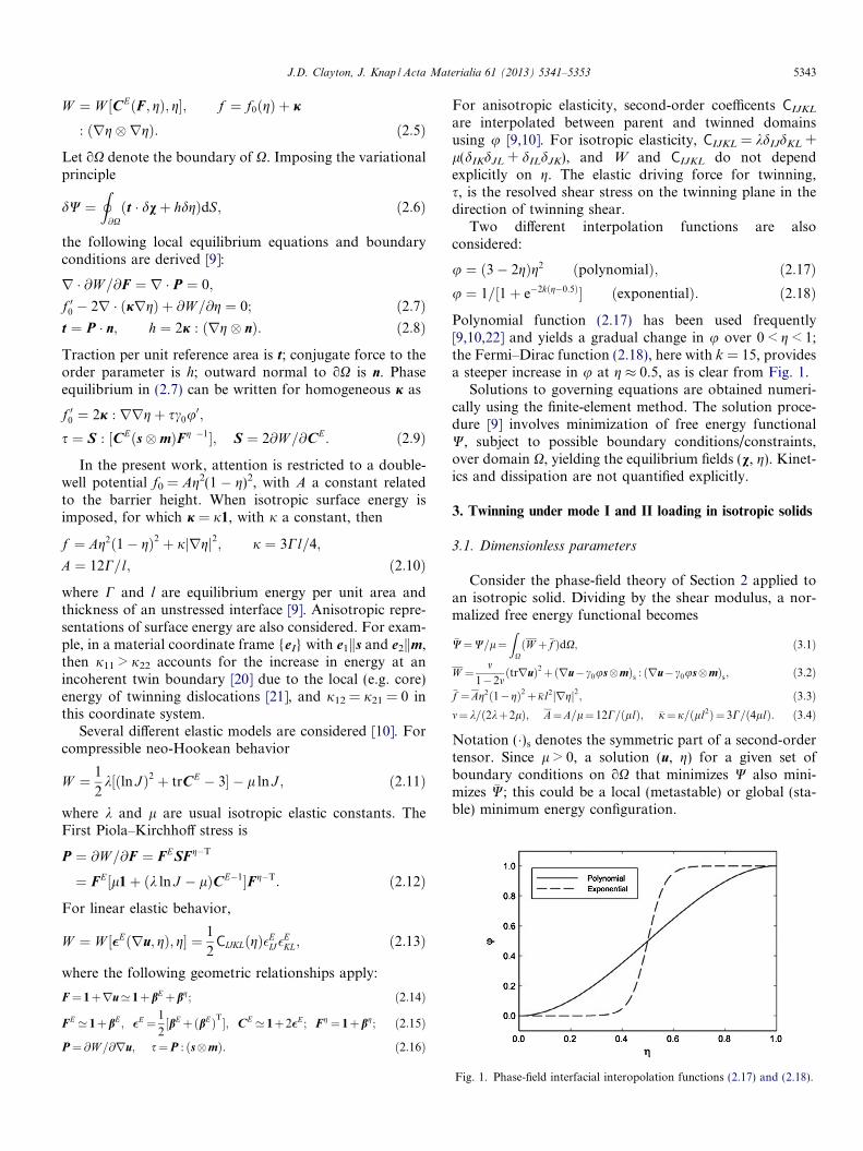
u ¼ ð3� 2gÞg2 ðpolynomialÞ; ð2:17Þu ¼ 1=½1þ e�2kðg�0:5Þ� ðexponentialÞ: ð2:18Þ
Polynomial function (2.17) has been used frequently[9,10,22] and yields a gradual change in u over 0 < g < 1;the Fermi–Dirac function (2.18), here with k = 15, providesa steeper increase in u at g � 0.5, as is clear from Fig. 1.
Solutions to governing equations are obtained numeri-cally using the finite-element method. The solution proce-dure [9] involves minimization of free energy functionalW, subject to possible boundary conditions/constraints,over domain X, yielding the equilibrium fields (v, g). Kinet-ics and dissipation are not quantified explicitly.
3. Twinning under mode I and II loading in isotropic solids
3.1. Dimensionless parameters
Consider the phase-field theory of Section 2 applied toan isotropic solid. Dividing by the shear modulus, a nor-malized free energy functional becomes
�W¼W=l¼Z
XðW þ �f ÞdX; ð3:1Þ
W ¼ m1�2m
ðtrruÞ2þðru� c0us�mÞs : ðru� c0us�mÞs; ð3:2Þ�f ¼Ag2ð1�gÞ2þ �jl2jrgj2; ð3:3Þm¼ k=ð2kþ2lÞ; A¼A=l¼ 12C=ðllÞ; �j¼j=ðll2Þ¼ 3C=ð4llÞ: ð3:4Þ
Notation (�)s denotes the symmetric part of a second-ordertensor. Since l > 0, a solution (u, g) for a given set ofboundary conditions on oX that minimizes W also mini-mizes �W; this could be a local (metastable) or global (sta-ble) minimum energy configuration.
Fig. 1. Phase-field interfacial interopolation functions (2.17) and (2.18).

5344 J.D. Clayton, J. Knap / Acta Materialia 61 (2013) 5341–5353
Let C0 denote a constant reference value of twin bound-ary surface energy per unit area, and let A0 and �j0 denotethe corresponding values of parameters in (3.4) for fixedl = l0 and fixed l. Then
C=C0 ¼ A=A0 ¼ �j=�j0: ð3:5ÞIn all subsequent analysis l is held fixed. In what follows,representative values of C0 = 100 mJ m�2 andl0 = 25 GPa, with l = 1.0 nm [9,10,22], are used to establishA0 and �j0. During simulations, the effect of surface energy isthen studied by varying C/C0. In most simulations, isotropicsurface energy is assumed, but in some (2-D) simulations,j11 = aj22 = aj is prescribed, where a > 1 accounts forincoherent boundary energy as noted in Section 2. (For atwin system oriented differently from ske1 and mke2, j is ro-tated as a second-order tensor.) Accordingly, for a given setof boundary conditions and prescribed initial crystal orien-tation (s, m), solutions thus obtained depend on the param-eter set (c0, m, C/C0, a) and choice of interpolation functionu. The same arguments apply for the isotropic neo-Hook-ean elastic model of Section 2.
Plane-strain simulations of an initially square domain Xof size 2a � 2a are reported in Section 4. The domain con-tains a pre-existing straight edge crack of length a andthickness 2r0, with a rounded tip of radius r0. The crackis assigned a finite radius for two reasons: (i) a perfect slitcrack would result in truly singular stress fields at the tipthat cannot be fully resolved with conventional finite ele-ments; and (ii) in a real material a finite r0 on the orderof or exceeding a lattice parameter is expected since theseparation distance across opposite faces of the crackshould exceed a cut-off distance for interatomic cohesiveforces that would otherwise result in traction across oppos-ing faces of the crack.
Let the origin of reference coordinate systems ((r, h) inpolar form or (X, Y) in rectangular form) be located atthe crack tip. Boundary conditions are imposed as follows.The crack surface N (h = ±p rad, 0 < r < a) is free of trac-tion (t = 0). Neumann conditions h = 0 for conjugate forceto the order parameter are assigned along all of oX. Alongexternal boundary oXnN corresponding to X, Y = ±a, dis-placements uðr; hÞ corresponding to the K field for puremode I or mode II loading [23] are imposed. For mode I:
uX ¼ 2D½ar=ð2pÞ�1=2 cosðh=2Þ½1� 2mþ sin2ðh=2Þ�; ð3:6ÞuY ¼ 2D½ar=ð2pÞ�1=2 sinðh=2Þ½2� 2m� cos2ðh=2Þ�; ð3:7ÞD ¼ KI=ð2la1=2Þ: ð3:8Þ
For mode II:
uX ¼ 2D½ar=ð2pÞ�1=2 sinðh=2Þ½2� 2mþ cos2ðh=2Þ�; ð3:9ÞuY ¼ �2D½ar=ð2pÞ�1=2 cosðh=2Þ½1� 2m� sin2ðh=2Þ�; ð3:10ÞD ¼ KII=ð2la1=2Þ: ð3:11Þ
For both modes, the orientation of the twin system (s, m) issuch that the resolved shear stress s of (2.16) is maximum
according to the linear elastic solution [23]. For mode II,s is simply oriented in the sense of positive r along h = 0.For mode I, s is oriented in the sense of positive r alongh = 1.22 rad.
During phase-field simulations, D is increased incremen-tally. For each increment, the domain is seeded with a smalltwin nucleus at r 6 r0. Displacement boundary conditionsare updated according to the mode of loading via (3.6),(3.7), (3.8) or (3.9), (3.10), (3.11), and then the equilibriumsolution (u, g) in X is obtained through energy minimizationusing the finite-element method. If the driving force fortwinning is insufficient, then the initial nucleus will disap-pear, and the equilibrium solution includes g = 0"X 2 X.Otherwise, at a threshold load parameter D = DT, a stabletwin will appear at the crack tip (r = 0). With furtherincreasing D > DT, the twin will grow in length and/or thick-ness until it interacts with the external boundary oXnN.
According to linear elastic fracture mechanics, crackextension (i.e. cleavage) will occur if the applied stressintensity factor or corresponding strain energy release rateexceeds a threshold for a particular material and loadingmode:
KI=II P KC () GI=II P GC ) fracture; ð3:12Þ
where the fracture surface energies are
GI=II ¼ K2I=IIð1� mÞ=ð2lÞ;
GC ¼ K2Cð1� mÞ=ð2lÞ; ð3:13Þ
and here no distinction has been made in notation amongthreshold fracture energies GC for different modes. Forcomparison, dimensionless twinning and fracture parame-ters associated with the normalized strain energy requiredfor either mechanism can be constructed:
CT ¼ CT=ðllÞ ¼ að1� mÞD2T=l; GC ¼ GC=ðllÞ: ð3:14Þ
The following criteria then emerge that predict either crackextension or twin emission from the crack tip:
2CT=GC ¼ 2CT=GC � 1) fracture;
2CT=GC ¼ 2CT=GC 1) twinning: ð3:15Þ
Dimensionless CT can be interpreted as an inverse measureof the “twinnability” of a given material subjected to modeI or mode II loading, with smaller values of CT denoting anincreased tendency for crack tip twinning. The factor oftwo arises because, in the usual convention of fracturemechanics, the strain energy release rate GC is twice thefracture surface energy CC. (In this paper, notation “C”
is associated generically with surface energy, “G” withstrain energy release.) When 2CT � GC, strain energy re-leased by twinning and crack extension are comparable,and either mechanism could be expected to occur. Notethat because D / a�1/2, imposed displacements u and twin-ning resistance CT do not depend on a, which serves merelyas a normalization constant to render these quantitiesdimensionless.

Table 2Other simulation parameters.
Descriptor Difference from basic parameters
Neo-Hookean Neo-Hookean elastic energyExponential interpolant Exponential uAnisotropic j a = j11/j22 = 100Thin notch r0/l = 0.5
J.D. Clayton, J. Knap / Acta Materialia 61 (2013) 5341–5353 5345
In phase-field simulations, meshes are used with signifi-cant refinement (element size l) near the crack tip andalong the anticipated path of twin extension, such thatsolutions are independent of mesh resolution. Twin nucle-ation depends strongly on local fields near r = 0 but notstrongly on a; further increasing the domain size abovea/l = 50 did not significantly affect initial stages of twin-ning, but as the twin grows and approaches the boundary,the choice of a necessarily affects the solution. Solutionscan be modestly dependent on notch radius for small r0,so two choices of r0 are explored. Tables 1 and 2 list param-eters investigated in simulations reported subsequently inSection 4. The typical (i.e. usual) parameter set referredto as “linear elastic” in subsequent figures is given inTable 1. Normalized twin boundary energy isC0 ¼ C=ðllÞ. Deviations from these parameters referredto in some later figures are explained in Table 2. In partic-ular, the value of a = 100 follows from Refs. [20,21].
3.2. Numerical results
Figs. 2 and 3 show characteristic results for mode I andmode II loading, respectively. The undeformed finite-ele-ment (FE) mesh is shown in part (a) of each figure. Twinmorphology and a stress component—tensile stress formode I, shear stress for mode II—are shown in parts (b)and (c), corresponding to a load increment exceedingnucleation, i.e. D > DT. In each case, the twin (i.e. stress-free shear eigenstrain c0/2) relieves much of the stress thatwould otherwise be large as r! 0 in an elastic mediumwithout a twin. Twin growth to the boundary oX is inhib-ited by the displacement boundary conditions.
Twin morphologies for various simulations of mode Ideformation are compared at the same load incrementD = 0.04 > DT, i.e. at the same imposed KI, in Fig. 4.Because differences in twin size and shape are small, it isconcluded that model predictions of fully formed twinmorphology are not sensitive to choice of linear or nonlin-ear (i.e. neo-Hookean) elastic model, choice of interpola-tion function (2.17) or (2.18), twin boundary surfaceenergy anisotropy a, or pre-existing thickness of the crackor notch. However, as discussed later, twin nucleation isaffected by these choices in some cases.
Fig. 5 shows the effects of dimensionless material prop-erties on twinning resistance 2CT of (3.14) under mode Iloading. Recall from (3.15) that this resistance can be com-pared with GC to predict whether twinning or cleavagecrack extension would be energetically favorable, withsmaller CT suggesting a greater tendency for twinning atthe crack tip. Each data point on each piecewise linearcurve in Fig. 5 represents the result of a different phase-field
Table 1Basic simulation parameters.
Descriptor Elasticity model u r0/l a C0
Linear elastic Linear isotropic Polynomial 2 1 4 � 10�3
simulation in which D (i.e. KI) is increased in incrementsof 10�3 from D = 0 to the condition for which a twin ortwin nucleus is first observed at D = DT.
Effects of twinning shear c0 on crack tip twinnability areshown in Fig. 5a, where discrete values of c0 = (0.1, 0.3,0.5, 0.7, 1.0) have been prescribed in simulations incorpo-rating linear elastic or neo-Hookean strain energy densityW. Twinning shear significantly affects nucleation. A min-imum of twinning resistance CT is predicted at c0 = 0.3 foreach model. For c0 < 0.3, resistance increases since theeigenstrain does not reduce elastic energy so much. Nucle-ation resistance also increases for c0 > 0.3, presumablybecause the applied KI field must be sufficiently strong suchthat a large eigenstrain relieves the elastic stress fieldinduced by the crack.
The effects of Poisson’s ratio m on twin nucleation resis-tance are comparatively small, as shown in Fig. 5b for val-ues of m = (0.05, 0.15, 0.25, 0.35, 0.45). The low influence ofPoisson’s ratio on twinning found here agrees with conclu-sions of a previous linear elastic analysis [24]. Neo-Hook-ean elasticity is more sensitive than linear elasticity to m,as expected considering the nonlinear compressibilityinherent in (2.11).
As shown in Fig. 5c, twin boundary energy C0 stronglyaffects twinnability, with resistance CT increasing withincreasing C/C0 in all cases. Discrete values C/C0 = (0.5,0.75, 1, 1.5, 2) have been probed. Twinning resistanceincreases relative to the linear elastic case when the expo-nential interpolator of (2.18), anisotropic surface energy(a = 100) or a thinner notch/crack is used. Differencesincrease as the ratio C/C0 increases.
Fig. 6 shows effects of dimensionless material propertieson twinning resistance 2CT of (3.14) under mode II loading,and is analogous to results for mode I of Fig. 5. Again,each data point represents the result of a different phase-field simulation in which D (here proportional to KII) isincreased in increments of 1 � 10�3 from D = 0 to the con-dition for which a twin or twin nucleus is first observed atD = DT.
The effects of twinning shear c0 on crack tip twinnabilityare shown in Fig. 6a, where discrete values of c0 = (0.1, 0.3,0.5, 0.7, 1.0) have been prescribed in simulations incorpo-rating linear elastic or neo-Hookean strain energy W.Twinning shear significantly affects mode II nucleation,as was the case for mode I. Here, a minimum of twinningresistance CT is predicted at c0 = 0.5 for each model inmode II loading, which exceeds the minimum associatedc0 = 0.3 observed for mode I.
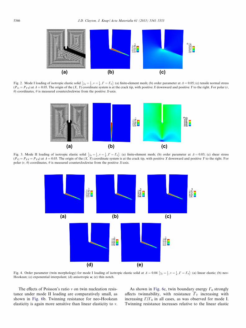
Fig. 2. Mode I loading of isotropic elastic solid c0 ¼ 12; m ¼ 1
4;C ¼ C0
� �: (a) finite-element mesh; (b) order parameter at D = 0.05; (c) tensile normal stress
(P11 = PYY) at D = 0.05. The origin of the (X, Y) coordinate system is at the crack tip, with positive X downward and positive Y to the right. For polar (r,h) coordinates, h is measured counterclockwise from the positive X-axis.
Fig. 3. Mode II loading of isotropic elastic solid c0 ¼ 12; m ¼ 1
4;C ¼ C0
� �: (a) finite-element mesh; (b) order parameter at D = 0.03; (c) shear stress
(P12 = PXY = PYX) at D = 0.03. The origin of the (X, Y) coordinate system is at the crack tip, with positive X downward and positive Y to the right. Forpolar (r, h) coordinates, h is measured counterclockwise from the positive X-axis.
Fig. 4. Order parameter (twin morphology) for mode I loading of isotropic elastic solid at D ¼ 0:04 c0 ¼ 12; m ¼ 1
4;C ¼ C0
� �: (a) linear elastic; (b) neo-
Hookean; (c) exponential interpolant; (d) anisotropic j; (e) thin notch.
5346 J.D. Clayton, J. Knap / Acta Materialia 61 (2013) 5341–5353
The effects of Poisson’s ratio m on twin nucleation resis-tance under mode II loading are comparatively small, asshown in Fig. 6b. Twinning resistance for neo-Hookeanelasticity is again more sensitive than linear elasticity to m.
As shown in Fig. 6c, twin boundary energy C0 stronglyaffects twinnability, with resistance CT increasing withincreasing C/C0 in all cases, as was observed for mode I.Twinning resistance increases relative to the linear elastic

Fig. 5. Normalized twin nucleation energy CT under mode I loading for (a) variable twinning shear c0; (b) variable Poisson’s ratio m; and (c) variable twinboundary surface energy C. A low value of CT correlates with a low value of applied KI needed to initiate a twin at the crack tip.
J.D. Clayton, J. Knap / Acta Materialia 61 (2013) 5341–5353 5347
case when the exponential interpolator of (2.18) or aniso-tropic surface energy (a = 100) is used, though the latterinfluences the results modestly and only for C/C0 > 1. Con-trary to results for mode I loading, a thinner notch reducesrather than increases twin resistance under mode II. Differ-ences among cases in Fig. 6c increase as C/C0 increases.
Comparing results in Figs. 5 and 6, numerical values ofresistance to twinning CT under mode I loading tend toexceed those under mode II by a factor of the order of 2.For example, for linear elasticity with the parameter set[c0 ¼ 1
2; m ¼ 1
4;C ¼ C0], phase-field simulations predict
CT � 0:007 for mode II and CT � 0:011 for mode I. Thisresult is not unexpected since a minimum twinning resis-tance would be associated with the geometry of mode IIloading in Fig. 3, i.e. with the twin system aligned perfectlywith maximum shear stress at the tip of a mode II crack.
4. Twinning under mode I loading in single crystals
Twinning under mode I loading of a square domain withpre-existing edge crack is investigated next for single crys-tals with relevant physical properties. Plane-strain simula-tions on a sample of dimensions identical to that ofSection 3 are reported. In this 2-D idealization, only onetwin system is permitted to be active in any simulation,and the crack propagation direction in a particularcleavage plane is chosen such that crack opening is in theplane h = ±p rad, i.e. the pre-existing crack is along
Y = 0, X < 0. Details regarding properties and results arereported in Table 3; corresponding discussion for eachmaterial follows next. As will become clear later, “Model”in Table 3 designates the type of elasticity model and/ortwin boundary surface energy representation, with “isotro-pic” referring to isotropic linear elasticity and isotropic sur-face energy (a = 1), “aniso. W” referring to anisotropiclinear elasticity and isotropic surface energy, and“a = 100” denoting isotropic linear elasticity with aniso-tropic surface energy.
4.1. Calcite
Calcite is a soft mineral of trigonal symmetry whosepure crystals are transparent. Calcite twins readily, with lit-tle or no plastic slip, under concentrated surface loading.The preferred twin system is e+, with relatively large shearc0 = 0.694 and geometry h1 00i{011} in rhombohedralpseudocell notation [25]. Calcite also cleaves easily on thenatural rhombohedral planes (i.e. {10 0} planes) of itsprimitive unit cell, equivalent to f10�11g planes in the hex-agonal notation of Refs. [26,27]. In the present simulations,a 2-D projection is required, where h = 0.89 rad is theresulting orientation of the e+ twin system that receivesthe maximum stress s under mode I loading of a cleavageplane. Cleavage surface energy entering GC in Table 3 isobtained from experiments [27]. Properties associated withtwinning and elasticity are from Ref. [10] and references

Fig. 6. Normalized twin nucleation energy CT under mode II loading for (a) variable twinning shear c0; (b) variable Poisson’s ratio m; (c) variable twinboundary surface energy C. A low value of CT correlates with a low value of applied KII needed to initiate a twin at the crack tip.
Table 3Single-crystal properties and results of phase-field simulations.
Material m l (GPa) Crack GC Twin system c0 2C0 Model 2CT=GC Prediction
Calcite 0.30 40 ð10�11Þ 0.017 e+ 0.694 0.0091 aniso. W 2.53 FractureIsotropic 2.96 Fracture
Sapphire 0.23 167 (0001) 0.48 Rhomb. (R) 0.202 0.0015 Isotropic 0.02 TwinningMax. s 0.1 a = 100 0.11 Twinningð10�12Þ 0.072 Basal (B) 0.635 0.0089 Isotropic 0.62 EitherMax. s 0.1 a = 100 0.65 Either
Mg 0.28 19 (0001) 382 ½10�11�ð�1012Þ 0.130 0.0121 Isotropic 2 � 10�4 Twinning
5348 J.D. Clayton, J. Knap / Acta Materialia 61 (2013) 5341–5353
therein. Both isotropic and anisotropic elastic models areinvestigated (i.e. forms of W). For the former, the Voigtelastic constants shown in Table 3 apply. For the latter,values (C11 = 165, C12 = 65, C13 = 62, C14 = �23,C33 = 89, C44 = 37 GPa) from Ref. [10] are used. For eitherelastic model, the displacement field of (3.6) and (3.7) isapplied by incrementally increasing D or, equivalently,KI; this is an approximation of the true KI field when aniso-tropic elasticity is used.
Results in Fig. 7a and b show the twin at loading soonafter nucleation, i.e. at D = 0.044 J DT. Nucleationoccurs first for the anisotropic model, but the orientation(h � 0.9 rad) and shape of the twin are similar in each case.A secondary twin belonging to the same twin system beginsto form at a larger applied KI field, as shown in Fig. 7c. For
anisotropic and isotropic models, 2:5 K 2CT=GC K 3,meaning that crack extension is preferred over twinningaccording to criterion (3.15). This result is in qualitativeagreement with tensile fracture experiments [26,27] thatreport no evidence of twinning. Parting fractures inducedby twins in calcite have also been noted [28]. These modelresults do not contradict the possibility of twins induced bydefects during other modes of loading, e.g. under sphericalindentation, samples with visible surface cracks are knownto twin more easily than those without [5].
4.2. Sapphire
Sapphire, also known as corundum or single-crystal alu-mina, is a hard ceramic/mineral that, like calcite, is of tri-

Fig. 7. Order parameter for mode I cleavage of calcite single crystal: (a) anisotropic elasticity, D = 0.044; (b) isotropic elasticity, D = 0.044; (c) isotropicelasticity, D = 0.1.
J.D. Clayton, J. Knap / Acta Materialia 61 (2013) 5341–5353 5349
gonal elastic symmetry and can be transparent. Asreviewed in Refs. [4,10], the twin systems are rhombohedral(R) with Miller indices h1�10�1if1�102g in the structuralunit cell, and basal (B) with Miller indices h1�100if0001gin the structural unit cell. Twinning shear for R systems(c0 = 0.202) is less than that for B systems (c0 = 0.635).Surface energies for cleavage on rhombohedral, prismaticand basal planes have been reported, with R planes themost likely to cleave and B planes difficult to fracture[29]. In various phase-field simulations reported next, eithera B twin system or a R twin system is active, with a mode Icrack located on one of several possible planes. Specifically,the four cases reported in Table 3 correspond to (i) R twin-ning induced by a basal plane crack (s at h = 1.07 rad); (ii)R twinning induced by a noncrystallographic plane crackthat produces maximum s (s at h = 1.22 rad); (iii) B twin-ning induced by a rhombohedral plane crack (s ath = 1.07 rad); and (iv) B twinning induced by noncrystallo-graphic plane crack that produces maximum s (s ath = 1.22 rad). Cleavage surface energies entering GC inTable 3 are obtained from [29]. For cases (i) and (iii), iso-tropic surface energy is used. For cases (ii) and (iv), theeffects of anisotropic j associated with incoherent twinboundary energy are explored by setting a = 100 [21,20].In all cases, isotropic elasticity is imposed with Voigt elasticconstants, noting from previous work [10] that the effects ofelastic anisotropy are small in sapphire; elastic anisotropyis also investigated later in 3-D simulations in Section 5,confirming this assertion.
Fig. 8. Order parameter for mode I cleavage of sapphire single crystal: (a) btwinning and basal cleavage, D = 0.046.
Results for cases (i) and (iii) are shown in Fig. 8a and bat D > DT. The basal twin (Fig. 8a) nucleates at a larger Dand is thinner than the rhombohedral twin (Fig. 8b). Twin-ning resistance is compared with fracture energy in Table 3.Since 2CT GC for cases (i) and (ii) involving R twinning,this twinning mode is preferred over mode I crack exten-sion. On the other hand, 2CT is smaller than GC, but notsignificantly so, for cases (iii) and (iv) involving basal twin-ning. It follows that basal twinning is possible in suchcases, but crack extension is also likely, considering possi-ble sources of uncertainty in the phase-field model/param-eters and local variations in microstructure (e.g. defects orimpurities) inherent in real experimental samples. Predic-tions are in qualitative agreement with experiments. Specif-ically, in cleavage experiments [29], basal fracture wasfound much more difficult to induce than rhombohedralfracture. In recovered specimens fractured by bending[30] on unidentified planes, numerous thicker R twins werefound, and fewer thinner B twins were observed. Thethicker predicted shape of the R twin relative to the B twinis evident in Fig. 8; it has been noted elsewhere [28] thattwin systems with larger c0 are prone to yield thinner twins.The presence of both kinds of twins has been reported inshock compression experiments on alumina polycrystals [3].
4.3. Magnesium
Magnesium is a moderately ductile metal with hexago-nal crystal structure. A number of slip and twin systems
asal twinning and rhombohedral cleavage, D = 0.057; (b) rhombohedral

Fig. 9. Order parameter for mode I basal plane cleavage of magnesium crystal: (a) twin nucleation, D = 0.044; (b) tensile twinning, D = 0.1.
5350 J.D. Clayton, J. Knap / Acta Materialia 61 (2013) 5341–5353
have been identified; the twin system investigated here isthe dominant inelastic mechanism observed in single crys-tals stretched along [000 1]: the system h10�11if�1012g,with relatively small shear c0 = 0.1295. Elastic anisotropyis very low in Mg; Voigt isotropic elastic constants [9] areused, along with the isotropic twin boundary surfaceenergy listed in Ref. [9]. Although various cleavage modesin single crystals have been reported [31], quantitative val-ues of fracture surface energies are not evident in the exist-ing literature; however, analysis suggests that the fractureenergies of prismatic and basal planes should be approxi-mately equal [32]. In the present work, a pre-existing edgecrack on the basal plane is modeled, where the value of GC
Fig. 10. Order parameter for direct shear loading (c = 1) of sapphire single crysand anisotropic surface energy; (b) basal twin, isotropic elasticity and isotanisotropic surface energy; (d) rhombohedral twin, isotropic elasticity and iso
in Table 3 is obtained from the macroscopic fracturetoughness of Mg polycrystals [33]. The most favorably ori-ented twin system is oriented with s at h = 0.75 rad.
The predicted twin is shown in Fig. 9a at D � DT and inFig. 9b at D > DT. The rounded shape of the twin nucleusin Fig. 9a is in qualitative agreement with previous theoret-ical studies [9,34]. The symmetric double-twin morphologyin Fig. 9b is similar to atomic simulation results of tensiletwinning in a Mg single crystal with a pre-existing centercrack on the basal plane [35] (see their Fig. 4). In the pres-ent simulations, the blunt shape of the twin(s) correlateswith the low value of c0 in Mg. Twinning resistance is com-pared with fracture energy in Table 3. Since 2CT GC,
tal with halfpenny-shaped edge notch: (a) basal twin, anisotropic elasticityropic surface energy; (c) rhombohedral twin, anisotropic elasticity andtropic surface energy.

Fig. 11. Twin nucleation and growth along mid-plane Y = 0 for direct shear loading of sapphire single crystal, anisotropic model, basal twin: (a) c = 0.2;(b) c = 0.4; (c) c = 0.6; (d) c = 0.8; (e) c = 1.0.
Fig. 12. Twin nucleation and growth along mid-plane Y = 0 for direct shear loading of sapphire single crystal, anisotropic model, rhombohedral twin: (a)c = 0.2; (b) c = 0.4; (c) c = 0.6; (d) c = 0.8; (e) c = 1.0.
J.D. Clayton, J. Knap / Acta Materialia 61 (2013) 5341–5353 5351
twinning is preferred over mode I crack extension for thepresent boundary conditions.
The analytical model of Ref. [8] suggests the followingcriterion for twinning vs. crack extension:
v � ðfT=fCÞ1=2> 1) fracture;
v � ðfT=fCÞ1=2< 1) twinning; ð4:1Þ
where the dimensionless parameter v depends on loaddirection, crystal structure (e.g. c/a ratio in hexagonal met-als) and anisotropic elastic constants, and fT and fC areenergies associated with “total inelastic resistance” againsttwin and crack extension, respectively. For basal planecleavage and tensile twinning, a value of v = 1.66 is re-ported for Mg [8]. Values of fT and fC have not been re-ported; the former can be deduced from the presentresults if fC ¼ 1
2GC is assumed. Squaring both sides of
(4.1) and comparing with (3.15) yields
fT ¼ CT=v2 ¼ llCT=v
2 � 0:26 J=m2; ð4:2Þwhich is significantly larger than the twin boundary surfaceenergy C = 0.12 J/m2. Such a result reinforces the notionthat total energetic resistance to twinning depends on otherfactors besides C alone.
5. Twinning in a notched single crystal: 3-D simulations
Three-dimensional simulations demonstrate how thephase-field model can be applied to predict twinning undercomplex stress states. In the present simulations of single-crystal sapphire, attention is restricted to a single potentiallyactive twin system. Boundary conditions imposing direct,intense shear strain resolved on this system (discussed in
detail below) are such that only one system would beexpected to be active. Various simulations consider eitherrhombohedral (R) or basal (B) twinning, with isotropic oranisotropic material models. For the former, isotropic twinboundary surface energy is also used. For the latter, the tri-gonal elastic constants (C11 = 500, C12 = 168, C13 = 121,C14 = 24, C33 = 502, C44 = 151 GPa) from Ref. [10] are used,and anisotropic twin boundary energy is imposed witha = 100. The remaining material properties have alreadybeen discussed in Section 4.2 in the context of Table 3.
Consider here is a cube of material with initial dimen-sions 4a � 4a � 4a, where a/l = 10. Six faces are labeled±X, ±Y, ±Z, where the unit normal of each face isaligned parallel to the corresponding axis in a globalCartesian coordinate system with origin at the center ofthe cube. A half-cylinder of radius a and height 2l isextracted from the �X face of the cube along the mid-plane Y = 0. This can be interpreted as a pre-existing,halfpenny-shaped notch or edge crack. Displacementboundary conditions are applied to the �X face and cre-ate a region of intense shear deformation of magnitude cover the region �l < Y < l, similar to conditions exploredin Ref. [36] for modeling slip, or to what might beobserved in the early stages of a dynamic Kalthoff exper-iment. Specifically, face �X is held fixed for�2a 6 Y 6 �l and displaced rigidly in the +X directionfor l 6 Y 6 2a. The opposite +X face is held fixed(u = 0), and lateral faces ±Y, ±Z are traction free. Allsurfaces comprising oX (six cube faces and the crack sur-face) are assigned the free (h = 0) Neumann condition forthe order parameter, enabling possible twin nucleation atany of these surfaces.

5352 J.D. Clayton, J. Knap / Acta Materialia 61 (2013) 5341–5353
Characteristic results are shown in Fig. 10 for animposed shear of unity (c = 1). Specifically, B twinning isdepicted in Fig. 10a and b, R twinning in Fig. 10c and d.For each mode of twinning, predictions of linear isotropicand anisotropic elasticity are similar for the order parame-ter (g) profile in the region of intense shear. Anisotropicsurface energy suppresses formation of the partial second-ary twins that emerge along the upper edge of the �X facein each of the isotropic simulations (Fig. 10b and d). Sim-ulations with neo-Hookean elasticity were also performed;the results were very similar to those shown for linear iso-tropic elasticity and are not shown. Consistent with theresults of 2-D simulations in Section 4.2 and experimentalobservations [30], basal twinning is more difficult to enactthan rhombohedral twinning under the present direct shearboundary conditions, and B twins tend to be thinner thanR twins.
Order parameter contours along mid-plane Y = 0 areshown in Figs. 11 and 12, respectively, for B and R twin-ning for incrementally increasing applied deformation c.Some asymmetry of the twin boundary front is evident,particularly for the B twin in Fig. 11, a consequence ofanisotropy. In these simulations, the semicircular edgecrack does not promote or inhibit twinning; however, dif-ferent boundary conditions explored elsewhere in atomicsimulations of shock compression [37] have demonstratedthe possibility of R twinning induced at pre-existing planarcracks in sapphire.
6. Conclusions
Twin emission from a crack tip has been studied usingphase-field simulations. A parameter associated with resis-tance to twin nucleation under mode I/II loading has beenderived. This parameter can be compared with the fractureenergy of the material to suggest whether an existing crackshould extend or a deformation twin should emerge andgrow. Effects of material properties and phase-field modelfeatures on twinning resistance have been studied paramet-rically, with Poisson’s ratio and elastic nonlinearity show-ing little effect. In contrast, resistance to crack tiptwinning depends strongly on twin boundary surfaceenergy and twinning shear. Plane-strain simulations oftwinning induced by a pre-existing crack on relevant cleav-age planes in calcite, sapphire and magnesium single crys-tals have been conducted. Results suggest that calciteshould cleave, magnesium should twin, and that rhombo-hedral twinning is preferred to basal twinning in sapphire,all in agreement with experiment. Three-dimensional simu-lations of shear loading of sapphire demonstrate a prefer-ence for rhombohedral over basal twins, with the formerthicker in shape, in agreement with experiment.
References
[1] Christian J, Mahajan S. Deformation twinning. Prog Mater Sci1995;39:1–157.
[2] Tadmor E, Hai S. A Peierls criterion for the onset of deformationtwinning at a crack tip. J Mech Phys Solids 2003;51:765–93.
[3] Chen M, McCauley J, Dandekar D, Bourne N. Dynamic plasticityand failure of high-purity alumina under shock loading. NatureMater 2006;5:614–8.
[4] Clayton J. A continuum description of nonlinear elasticity, slip andtwinning, with application to sapphire. Proc Roy Soc Lond A2009;465:307–34.
[5] Garber R, Stepina E. Rules governing the motion of dislocationsduring deformation twinning. Soviet Phys Solid State 1965;5:152–8.
[6] Wong T, Bradt R. Microhardness anisotropy of single crystals ofcalcite, dolomite, and magnesite on their cleavage planes. MaterChem Phys 1992;30:261–6.
[7] Rice J. Dislocation nucleation from a crack tip: an analysis based onthe Peierls concept. J Mech Phys Solids 1992;40:239–71.
[8] Yoo M. Slip, twinning, and fracture in hexagonal close-packedmetals. Metall Trans A 1981;12:409–18.
[9] Clayton J, Knap J. A phase field model of deformation twinning:nonlinear theory and numerical simulations. Physica D2011;240:841–58.
[10] Clayton J, Knap J. Phase field modeling of twinning in indentation oftransparent single crystals. Mod Sim Mater Sci Eng 2011;19:085005.
[11] Clayton J. Nonlinear mechanics of crystals. Dordrecht: Springer;2011.
[12] Boulbitch A, Toledano P. Phase nucleation of elastic defects incrystals undergoing a phase transition. Phys Rev Lett 1998;81:838–41.
[13] Boulbitch A, Korzhenevskii A. Self-oscillating regime of crackpropagation induced by a local phase transition at its tip. Phys RevLett 2011;107:085505.
[14] Idesman A, Levitas V, Stein E. Structural changes in elastoplasticmaterial: a unified finite-element approach to phase transformation,twinning and fracture. Int J Plast 2000;16:893–949.
[15] Aranson I, Kalatsky V, Vinokur V. Continuum field description ofcrack propagation. Phys Rev Lett 2000;85:118–21.
[16] Jin Y, Wang Y, Khachaturyan A. Three-dimensional phase fieldmicroelasticity theory and modeling of multiple cracks and voids.Appl Phys Lett 2001;79:3071–3.
[17] Karma A, Kessler D, Levine H. Phase-field model of mode IIIdynamic fracture. Phys Rev Lett 2001;87:045501.
[18] Spatschek R, Hartmann M, Brener E, Muller-Krumbhaar H. Phasefield modeling of fast crack propagation. Phys Rev Lett2006;96:015502.
[19] Spatschek R, Brener E, Karma A. Phase field modeling of crackpropagation. Philos Mag 2011;91:75–95.
[20] Hildebrand F, Miehe C. A phase field model for the formation andevolution of martensitic laminate microstructure at finite strains.Philos Mag 2012;92:4250–90.
[21] Hu S, Henager C, Chen L-Q. Simulations of stress-induced twinningand de-twinning: a phase field model. Acta Mater 2010;58:6554–64.
[22] Levitas V, Levin V, Zingerman K, Freiman E. Displacive phasetransitions at large strains: phase-field theory and simulations. PhysRev Lett 2009;103:025702.
[23] Rice J. Mathematical analysis in the mechanics of fracture. In:Liebowitz H, editor. Fracture: an advanced treatise. New York: Aca-demic Press; 1968. p. 191–311.
[24] Bilby B, Bullough R. The formation of twins by a moving crack.Philos Mag 1954;45:631–46.
[25] Bueble S, Schmahl W. Mechanical twinning in calcite considered withthe concept of ferroelasicity. Phys Chem Minerals 1999;26:668–72.
[26] Gilman J. Direct measurements of the surface energy of crystals. JAppl Phys 1960;31:2208–18.
[27] Santhanam A, Gupta Y. Cleavage surface energy of calcite. Int JRock Mech Mining Sci Geo Abstr 1968;5:253–9.
[28] Cahn R. Plastic deformation of alpha-uranium; twinning and slip.Acta Metall 1953;1:49–70.
[29] Wiederhorn S. Fracture of sapphire. J Am Ceram Soc1969;52:485–91.

J.D. Clayton, J. Knap / Acta Materialia 61 (2013) 5341–5353 5353
[30] Heuer A. Deformation twinning in corundum. Philos Mag1966;13:379–93.
[31] Reed-Hill R, Robertson W. The crystallographic characteristics offracture in magnesium single crystals. Acta Metall 1957;5:728–37.
[32] Yoo M. The elastic energy of slit cracks in hexagonal crystals. ScrMetall 1979;13:131–6.
[33] Somekawa H, Inoue T, Mukai T. Deformation mechanism nearcrack-tip by finite element analysis and microstructure observation inmagnesium alloys. Mater Sci Eng A 2010;527:1761–8.
[34] Wang J, Hoagland R, Hirth J, Capolungo L, Beyerlein I, Tome C.Nucleation of a (1012) twin in hexagonal close-packed crystals.Scripta Mater 2009;61:903–6.
[35] Tang T, Kim S, Horstemeyer M, Wang P. Atomistic modeling ofcrack growth in magnesium single crystal. Eng Fract Mech2011;78:191–201.
[36] Gumbsch P, Gao H. Dislocations faster than the speed of sound.Science 1999;283:965–8.
[37] Kuksin A, Yanilkin A. Formation of twins in sapphire under shockwave loading: atomistic simulations. J Appl Phys 2012;111:033513.

NO. OF NO. OF
COPIES ORGANIZATION COPIES ORGANIZATION
1 DEFENSE TECHNICAL
(PDF) INFORMATION CTR
DTIC OCA
1 DIRECTOR
(PDF) US ARMY RESEARCH LAB
IMAL HRA
1 DIRECTOR
(PDF) US ARMY RESEARCH LAB
RDRL CIO LL
1 GOVT PRINTG OFC
(PDF) A MALHOTRA
ABERDEEN PROVING GROUND
35 DIR USARL
(PDF) RDRL CIH C
P CHUNG
J KNAP
RDRL WM
B FORCH
J MCCAULEY
P PLOSTINS
RDRL WML B
I BATYREV
B RICE
D TAYLOR
N WEINGARTEN
RDRL WML H
B SCHUSTER
RDRL WMM
J BEATTY
RDRL WMM B
G GAZONAS
C RANDOW
T SANO
RDRL WMM E
J SWAB
RDRL WMM F
M TSCHOPP
RDRL WMP
S SCHOENFELD
RDRL WMP B
C HOPPEL
D POWELL
S SATAPATHY
M SCHEIDLER
T WEERISOORIYA
RDRL WMP C
R BECKER
S BILYK
T BJERKE
D CASEM
J CLAYTON
D DANDEKAR
M GREENFIELD
R LEAVY
M RAFTENBERG
S SEGLETES
C WILLIAMS
RDRL WMP D
R DONEY
RDRL WMP E
S BARTUS