person: gomez, javier ([email protected]) status:...
TRANSCRIPT
Person: Gomez, Javier ([email protected]) Org: PHALLA
Status: PROCESSED Date: 11/7/2013 10:07:04 AM
Operational Safety Procedure Review and Approval Form # 29345(See ES&H Manual Chapter 3310 Appendix T1 Operational SafetyProcedure (OSP) and Temporary OSP Procedure for Instructions)
Type: OSP
Serial Number: ENP-13-29345-OSP
Issue Date: 11/7/2013
Expiration Date: 6/7/2016
Title: Commssioning of Hall A Moller Polarimeter for 11 GeV
Location:(where work is being performed) Experimental Hall A Location Detail:
Risk Classification: (See ES&H Manual Chapter 3210 Appendix T3 Risk Code Assignment)
Without mitigation measures (3 or 4): 3
With mitigation measures in place (N, 1, or 2): N
Reason: This document is written to mitigate hazard issues that are :Determined to have an unmitigated Risk code of 3 or 4
Owning Organization: PHALLA
Document Owner(s): Gomez, Javier ([email protected]) Primary
Supplemental Technical Validations
Electricity (Todd Kujawa) Magnetic Fields (Jennifer Williams) Personal Protective Equipment (Jennifer Williams)
Other Hazards: electrical (Charles Hightower)
Document History
Revision Reason for revision or update Serial number of superceded document
Comments forreviewers/approvers:
This document describes the upgraded Hall A Moller polarimeter, its operation andhazards. Concurrence is sought that it can be operated by staff and users forexperiments without further mitigating measures
Attachments
Procedure: 3310T1Form.pdfTHA: Document-17166_v3.pdf
Additional Files: 20131031_moller_osp_reduced.pdf
Review Signatures

Person : Subject Matter Expert : electrical Signed on 11/7/2013 10:41:18 AM by Charles Hightower([email protected])
Subject Matter Expert : Electricity Signed on 11/7/2013 10:10:55 AM by Todd Kujawa([email protected])
Subject Matter Expert : Magnetic Fields Signed on 11/7/2013 10:12:28 AM by Jennifer Williams([email protected])
Subject Matter Expert : Personal ProtectiveEquipment
Signed on 11/7/2013 10:12:32 AM by Jennifer Williams([email protected])
Approval Signatures
Division Safety Officer : PHALLA Signed on 11/7/2013 10:41:58 AM by Patrizia Rossi ([email protected]) Org Manager : PHALLA Signed on 11/7/2013 1:40:29 PM by Cynthia Keppel ([email protected]) Safety Warden : Experimental Hall A Signed on 11/7/2013 10:53:54 AM by Ed Folts ([email protected])

For questions or comments regarding this form contact the Technical Point-of-Contact Harry Fanning This document is controlled as an on line file. It may be printed but the print copy is not a controlled document. It is the user’s responsibility to ensure that the document is
the same revision as the current on line file. This copy was printed on 10/31/2013.
Page 1 of 3
fa
Operational Safety Procedure Form (See ES&H Manual Chapter 3310 Appendix T1
Operational Safety Procedure (OSP) and Temporary OSP Procedure for instructions.)
DEFINE THE SCOPE OF WORK Title: Commissioning of Hall A Moller Polarimeter for 11 GeV
Location: Hall A
Type: OSP
TOSP
Risk Classification (per Task Hazard Analysis attached) (See ESH&Q Manual Chapter 3210 Appendix T3 Risk Code Assignment.)
Highest Risk Code Before Mitigation (3 or 4): N
Highest Risk Code after Mitigation (N, 1, or 2): N
Document Owner(s): Javier Gomez Date: 10/31/13 Document History (Optional)
Revision: Reason for revision or update: Serial number of superseded
document
ANALYZE THE HAZARDS 1. Purpose of the Procedure – Describe in detail the reason for the procedure (what is being done and why).
This document describes the upgraded Hall A Moller polarimeter, its operation and hazards. Concurrence is sought that it can be operated by staff and users for experiments without further mitigating measures
2. Scope – include all operations, people, and/or areas that the procedure will affect.
Operation of the Hall A Moller polarimeter for Physics 3. Description of the Facility – include floor plans and layout of a typical experiment or operation.
See attached document 4. Authority and Responsibility:
4.1 Who has authority to implement/terminate
Javier Gomez/Hall A Work coordinator or designee 4.2 Who is responsible for key tasks
Javier Gomez
4.3 Who analyzes the special or unusual hazards (See ES&H Manual Chapter 3210 Appendix T1 Work Planning, Control,
and Authorization Procedure)
Hall A work coordinator or designee
4.4 What are the Training Requirements (See http://www.jlab.org/div_dept/train/poc.pdf)
x

Operational Safety Procedure Form
For questions or comments regarding this form contact the Technical Point-of-Contact Harry Fanning This document is controlled as an on line file. It may be printed but the print copy is not a controlled document. It is the user’s responsibility to ensure that the document is
the same revision as the current on line file. This copy was printed on 10/31/2013.
Page 2 of 3
5. Personal and Environmental Hazard Controls Including:
5.1 Shielding
N/A 5.2 Interlocks
See attached document 5.3 Monitoring systems
N/A
5.4 Ventilation
N/A
5.5 Other (Electrical, ODH, Trip, Ladder) (Attach related Temporary Work Permits or Safety Reviews as appropriate.)
See attached document 6 List Of Safety Equipment
Personal Protective Equipment
N/A
Special Tools
N/A
DEVELOP THE PROCEDURE 1. Associated Administrative Controls
None 2. Operating Guidelines
See attached document 3. Notification of Affected Personnel (who, how, and when)
See list of Authorized Personnel on attached document 4. List the Steps Required to Execute the Procedure: from start to finish.
See attached procedure 5. Back Out Procedure(s) i.e. steps necessary to restore the equipment/area to a safe level.
None 6. Special environmental control requirements:
6.1 Environmental impacts (See EMP-04 Project/Activity/Experiment Environmental Review)
None
6.2 Abatement steps (secondary containment or special packaging requirements)
7. Unusual/Emergency Procedures (e.g., loss of power, spills, fire, etc.)
None

Operational Safety Procedure Form
For questions or comments regarding this form contact the Technical Point-of-Contact Harry Fanning This document is controlled as an on line file. It may be printed but the print copy is not a controlled document. It is the user’s responsibility to ensure that the document is
the same revision as the current on line file. This copy was printed on 10/31/2013.
Page 3 of 3
8. Instrument Calibration Requirements (e.g., safety system/device recertification, RF probe calibration)
None 9. Inspection Schedules
None 10. References/Associated Documentation
Attached device description, operating procedure & hazards 11. List of Records Generated (Include Location / Review and Approved procedure)
Distribution: Copies to: affected area, authors, Division Safety Officer Expiration: Forward to ESH&Q Document Control
Form Revision Summary Revision 1.2 – 09/15/12 – Update form to conform to electronic review. Revision 1.1 – 04/03/12 – Risk Code 0 switched to N to be consistent with 3210 T3 Risk Code Assignment. Revision 1 – 12/01/11 - Added reasoning for OSP to aid in appropriate review determination. Revision 0 - 10/05/09 – Updated to reflect current laboratory operations
ISSUING AUTHORITY FORM TECHNICAL POINT-OF-CONTACT APPROVAL DATE REVIEW REQUIRED DATE REV.
ESH&Q Division Harry Fanning 12/01/11 12/01/14 1.2
This document is controlled as an on line file. It may be printed but the print copy is not a controlled document. It is the user’s responsibility to ensure that the document is the same revision as the current on line file. This copy was printed on 10/31/2013.

For questions or comments regarding this form contact the Technical Point-of-Contact Harry Fanning This document is controlled as an on line file. It may be printed but the print copy is not a controlled document. It is the user’s responsibility to ensure that the document is the same revision as the
current on line file. This copy was printed on 11/7/2013.
Page 1 of 2
Task Hazard Analysis (THA) Worksheet (See ES&H Manual Chapter 3210 Appendix T1
Work Planning, Control, and Authorization Procedure)
Author: Javier Gomez Date: November 7, 2013 Task #:
If applicable
Complete all information. Use as many sheets as necessary
Task Title: Moller Polarimeter Commissioning and Operation Task Location: Hall A
Division: Physics Department: Frequency of use:
Lead Worker: Mitigation already in place: Standard Protecting Measures Work Control Documents
Engineered Controls: Plexiglas covers are use to cover the magnet electrical connections. Magnet power supplies have their connections either secured inside a locked cabinet or surrounded with plexiglas.
Sequence of Task Steps Task Steps/Potential Hazards
Consequence Level
Probability Level
Risk Code (before
mitigation) Proposed Mitigation
(Required for Risk Code >2) Safety Procedures/
Practices/Controls/Training
Risk Code (after
mitigation
Work near beam line bellows and windows under vacuum M L 1
Use ear acoustic earmuffs and safety glasses when working in the neighborhood of these windows and bellows
N
Detector High Voltage (up to 3kV) M L 1 Turn-off HV channel before
connecting/disconnecting HV N
Magnetic field effect on individuals with electronic/ferromagnetic medical implants
M M 3
Barrier with signs indicating the presence of magnetic fields larger than 5 Gauss past the barrier
N
Highest Risk Code before Mitigation: 3 Highest Risk Code after Mitigation: N
Click
For Word Doc

Task Hazard Analysis (THA) Worksheet (See ES&H Manual Chapter 3210 Appendix T1
Work Planning, Control, and Authorization Procedure)
For questions or comments regarding this form contact the Technical Point-of-Contact Harry Fanning This document is controlled as an on line file. It may be printed but the print copy is not a controlled document. It is the user’s responsibility to ensure that the document is the same revision as the
current on line file. This copy was printed on 11/7/2013.
Page 2 of 2
When completed, if the analysis indicates that the Risk Code before mitigation for any steps is “medium” or higher (RC≥3), then a formal Work Control Document (WCD) is developed for the task. Attach this completed Task Hazard Analysis Worksheet. Have the package reviewed and approved prior to beginning work. (See ES&H Manual Chapter 3310 Operational Safety Procedure Program.)
Form Revision Summary Revision 0.1 – 06/19/12 - Triennial Review. Update to format. Revision 0.0 – 10/05/09 – Written to document current laboratory operational procedure.
ISSUING AUTHORITY
FORM TECHNICAL POINT-OF-CONTACT APPROVAL DATE EXPIRATION DATE REV.
ESH&Q Division Harry Fanning 06/19/12 06/19/15 0.1
This document is controlled as an on line file. It may be printed but the print copy is not a controlled document. It is the user’s responsibility to ensure that the document is the same revision as the current on line file. This copy was printed on 11/7/2013.
Hall A Møller Polarimeter
1 Purpose and Layout
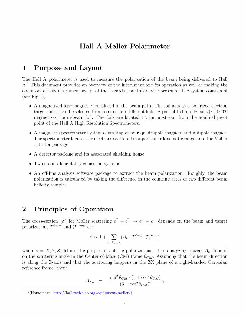
The Hall A polarimeter is used to measure the polarization of the beam being delivered to HallA.1 This document provides an overview of the instrument and its operation as well as making theoperators of this instrument aware of the hazards that this device presents. The system consists of(see Fig.1),
• A magnetized ferromagnetic foil placed in the beam path. The foil acts as a polarized electrontarget and it can be selected from a set of four different foils. A pair of Helmholtz coils (∼ 0.03Tmagnetizes the in-beam foil. The foils are located 17.5 m upstream from the nominal pivotpoint of the Hall A High Resolution Spectrometers.
• A magnetic spectrometer system consisting of four quadrupole magnets and a dipole magnet.The spectrometer focuses the electrons scattered in a particular kinematic range onto the Møllerdetector package.
• A detector package and its associated shielding house.
• Two stand-alone data acquisition systems.
• An off-line analysis software package to extract the beam polarization. Roughly, the beampolarization is calculated by taking the difference in the counting rates of two different beamhelicity samples.
2 Principles of Operation
The cross-section (σ) for Møller scattering ~e− + ~e− → e− + e− depends on the beam and targetpolarizations Pbeam and P target as:
σ ∝ 1 +∑
i=X,Y,Z
(Aii · P targi · Pbeam
i )
where i = X, Y, Z defines the projections of the polarizations. The analyzing powers Aii dependon the scattering angle in the Center-of-Mass (CM) frame θCM . Assuming that the beam directionis along the Z-axis and that the scattering happens in the ZX plane of a right-handed Cartesianreference frame, then:
AZZ = −sin2 θCM · (7 + cos2 θCM)
(3 + cos2 θCM)2,
1(Home page: http://hallaweb.jlab.org/equipment/moller/)
1
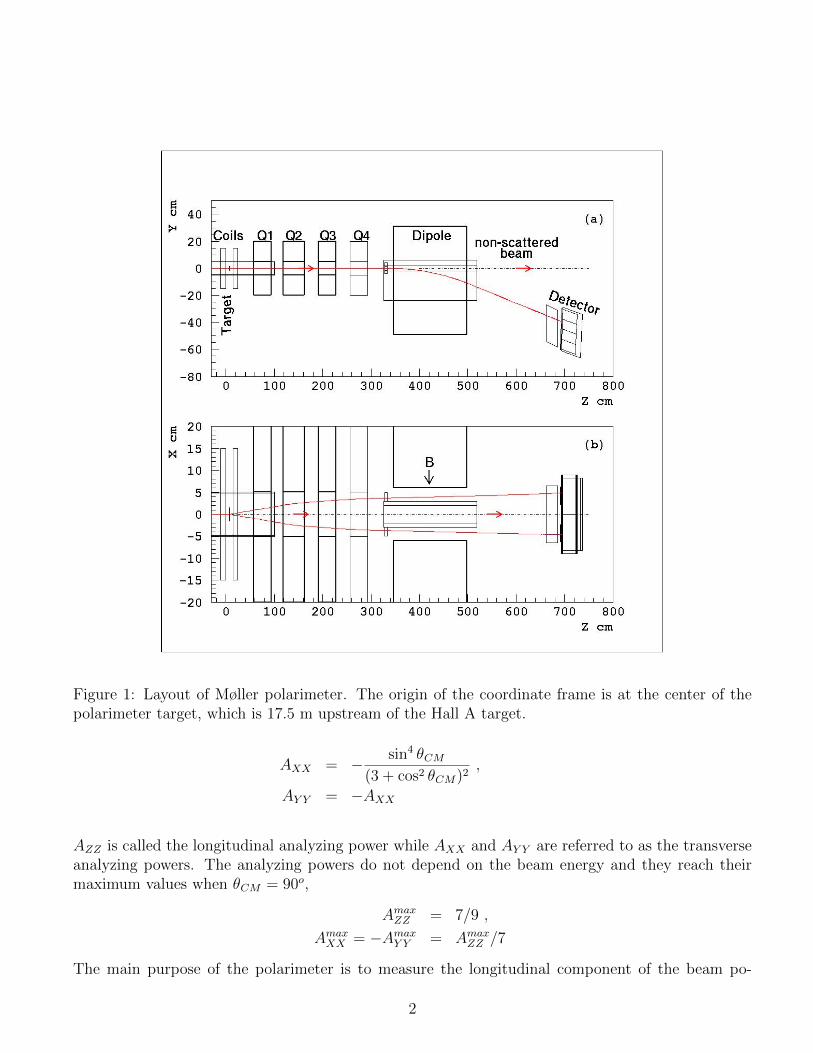
Figure 1: Layout of Møller polarimeter. The origin of the coordinate frame is at the center of thepolarimeter target, which is 17.5 m upstream of the Hall A target.
AXX = − sin4 θCM
(3 + cos2 θCM)2,
AY Y = −AXX
AZZ is called the longitudinal analyzing power while AXX and AY Y are referred to as the transverseanalyzing powers. The analyzing powers do not depend on the beam energy and they reach theirmaximum values when θCM = 90o,
AmaxZZ = 7/9 ,
AmaxXX = −Amax
Y Y = AmaxZZ /7
The main purpose of the polarimeter is to measure the longitudinal component of the beam po-
2

larization. The Møller polarimeter of Hall A detects pairs of scattered electrons in a range of75o < θCM < 105o with an average analyzing power of about < AZZ >= 0.76.
The target consists of a thin magnetically saturated ferromagnetic foil. In such a material, about 2electrons per atom can be polarized yielding an average electron polarization of about 8% for thefoil. The foil is magnetized (Pfoil) along its surface and it makes an angle θtarg of 20◦ with the thebeam in the vertical plane (see Fig. 3 and Chapter 3.2). The effective target polarization (P target)is,
P target = Pfoil · cos θtarg
Pfoil is determined from special magnetization measurements of the foil samples.
The scattered electron pairs pass through a magnetic spectrometer which selects particles in a particu-lar kinematic region. Two electrons are detected with a two-arm detector system and the coincidencecounting rate of the two arms is measured. The beam longitudinal polarization is then calculated as:
PbeamZ =
N+ −N−
N+ +N−· 1
P target · < AZZ >
where N+ and N− are the measured counting rates with two opposite mutual orientation of the beamand target polarizations, while < AZZ > is obtained using Monte-Carlo calculation of the Møllerspectrometer acceptance.
3 Description of Components
3.1 Polarimeter Control
Control of the Møller polarimeter is divided into two separate sections,
• The operators in the Machine Control Center (MCC) have sole control over target motionand currents settings of the quadrupoles & dipole that make up the magnetic spectrometer ofthe polarimeter. To access the Graphical User Interface (GUI) screens used for control of thepolarimeter,
– Launch NewTools application located in any of the Hall A control computers.
– Select EDM (OPS) - it opens a new window labeled Accelerator Main Menu
– On the new screen, the left-button under the “Hall A” brings-up a drop-down menu.Select Hall A Moller Polarimeter Control. Fig. 2 shows the final screen.
• The user has control over target polarization. See section 3.2.
3
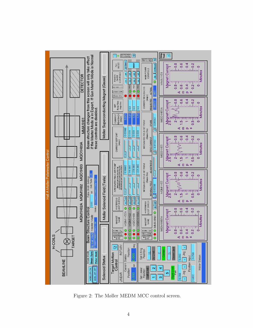
Figure 2: The Møller MEDM MCC control screen.
4
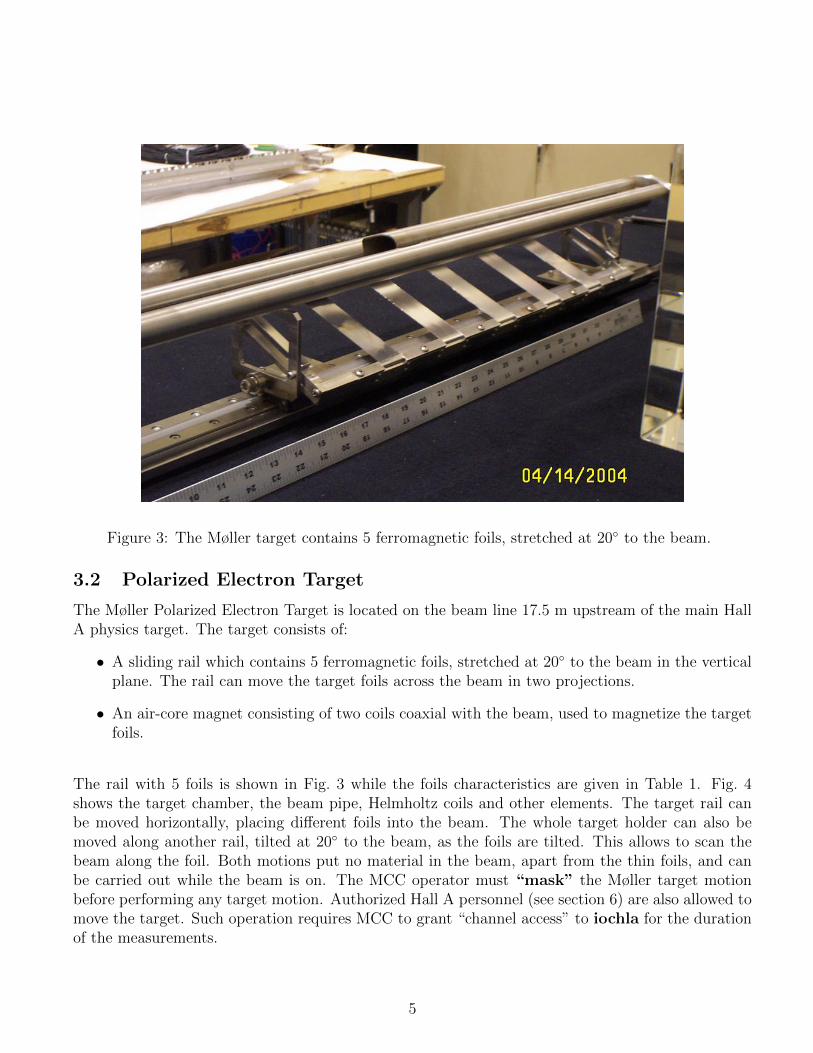
Figure 3: The Møller target contains 5 ferromagnetic foils, stretched at 20◦ to the beam.
3.2 Polarized Electron Target
The Møller Polarized Electron Target is located on the beam line 17.5 m upstream of the main HallA physics target. The target consists of:
• A sliding rail which contains 5 ferromagnetic foils, stretched at 20◦ to the beam in the verticalplane. The rail can move the target foils across the beam in two projections.
• An air-core magnet consisting of two coils coaxial with the beam, used to magnetize the targetfoils.
The rail with 5 foils is shown in Fig. 3 while the foils characteristics are given in Table 1. Fig. 4shows the target chamber, the beam pipe, Helmholtz coils and other elements. The target rail canbe moved horizontally, placing different foils into the beam. The whole target holder can also bemoved along another rail, tilted at 20◦ to the beam, as the foils are tilted. This allows to scan thebeam along the foil. Both motions put no material in the beam, apart from the thin foils, and canbe carried out while the beam is on. The MCC operator must “mask” the Møller target motionbefore performing any target motion. Authorized Hall A personnel (see section 6) are also allowed tomove the target. Such operation requires MCC to grant “channel access” to iochla for the durationof the measurements.
5
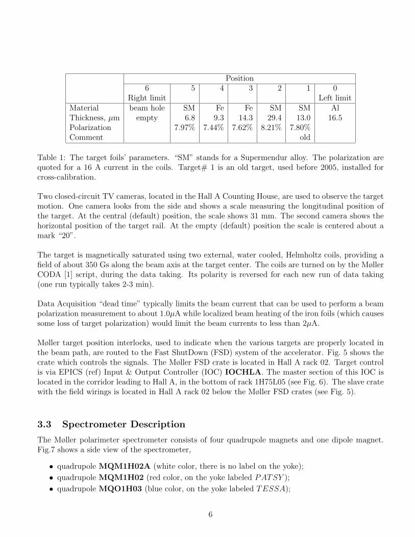
Position6 5 4 3 2 1 0
Right limit Left limitMaterial beam hole SM Fe Fe SM SM AlThickness, µm empty 6.8 9.3 14.3 29.4 13.0 16.5Polarization 7.97% 7.44% 7.62% 8.21% 7.80%Comment old
Table 1: The target foils’ parameters. “SM” stands for a Supermendur alloy. The polarization arequoted for a 16 A current in the coils. Target# 1 is an old target, used before 2005, installed forcross-calibration.
Two closed-circuit TV cameras, located in the Hall A Counting House, are used to observe the targetmotion. One camera looks from the side and shows a scale measuring the longitudinal position ofthe target. At the central (default) position, the scale shows 31 mm. The second camera shows thehorizontal position of the target rail. At the empty (default) position the scale is centered about amark “20”.
The target is magnetically saturated using two external, water cooled, Helmholtz coils, providing afield of about 350 Gs along the beam axis at the target center. The coils are turned on by the MøllerCODA [1] script, during the data taking. Its polarity is reversed for each new run of data taking(one run typically takes 2-3 min).
Data Acquisition “dead time” typically limits the beam current that can be used to perform a beampolarization measurement to about 1.0µA while localized beam heating of the iron foils (which causessome loss of target polarization) would limit the beam currents to less than 2µA.
Møller target position interlocks, used to indicate when the various targets are properly located inthe beam path, are routed to the Fast ShutDown (FSD) system of the accelerator. Fig. 5 shows thecrate which controls the signals. The Møller FSD crate is located in Hall A rack 02. Target controlis via EPICS (ref) Input & Output Controller (IOC) IOCHLA. The master section of this IOC islocated in the corridor leading to Hall A, in the bottom of rack 1H75L05 (see Fig. 6). The slave cratewith the field wirings is located in Hall A rack 02 below the Møller FSD crates (see Fig. 5).
3.3 Spectrometer Description
The Møller polarimeter spectrometer consists of four quadrupole magnets and one dipole magnet.Fig.7 shows a side view of the spectrometer,
• quadrupole MQM1H02A (white color, there is no label on the yoke);
• quadrupole MQM1H02 (red color, on the yoke labeled PATSY );
• quadrupole MQO1H03 (blue color, on the yoke labeled TESSA);
6
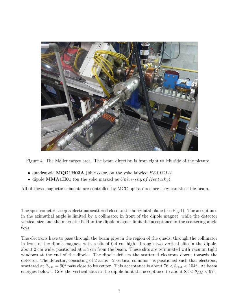
Figure 4: The Møller target area. The beam direction is from right to left side of the picture.
• quadrupole MQO1H03A (blue color, on the yoke labeled FELICIA)
• dipole MMA1H01 (on the yoke marked as University of Kentucky).
All of these magnetic elements are controlled by MCC operators since they can steer the beam.
The spectrometer accepts electrons scattered close to the horizontal plane (see Fig.1). The acceptancein the azimuthal angle is limited by a collimator in front of the dipole magnet, while the detectorvertical size and the magnetic field in the dipole magnet limit the acceptance in the scattering angleθCM .
The electrons have to pass through the beam pipe in the region of the quads, through the collimatorin front of the dipole magnet, with a slit of 0-4 cm high, through two vertical slits in the dipole,about 2 cm wide, positioned at ±4 cm from the beam. These slits are terminated with vacuum tightwindows at the end of the dipole. The dipole deflects the scattered electrons down, towards thedetector. The detector, consisting of 2 arms - 2 vertical columns - is positioned such that electrons,scattered at θCM = 90o pass close to its center. This acceptance is about 76 < θCM < 104o. At beamenergies below 1 GeV the vertical slits in the dipole limit the acceptance to about 83 < θCM < 97o.
7

Figure 5: The Møller target motion may cause the Fast ShutDown (FSD) of the accelerator. TheLEDs in the top right corner show the appropriate signals from the target. The top LED lit indicatesno FSD signal.
Energy range of the spectrometer is 0.8 GeV ÷ 11.0 GeV. For a given beam energy there is anoptimal setting of the currents in these 5 magnets. Typically, the dipole magnet should be turnedon only for the Møller measurements.
3.4 Detector
The Møller polarimeter detector is located in the shielding box downstream of the dipole and consistsof two identical modules placed symmetrically about a vertical plane containing the beam axis, thusenabling coincidence measurements (see Fig. 8). Each part of the detector includes:
• An aperture detector consists of four scintillators with light guides and Hamamatsu R4124(13 mm diameter) photomultiplier tubes connected to each segment. Size of the apertureassembled detector is 31cm×4cm×3.6cm.
• A spaghetti lead - scintillating fiber calorimeter2, consisting of 2 blocks
2before summer 2002 a lead glass calorimeter consisting of 4 8×8×30 cm3 was used. It lost a big fraction of the
8

Figure 6: EPICS IOC IOCHLA master crate is located in the corridor leading to Hall A in thebottom of rack 1H75L05.
9×15×30 cm3, each separated into 2 channels equipped with Photonis XP2282B (2 inch) photo-multiplier tubes. Thus, each of the vertical detectors is segmented into 4 calorimeter channels.
The HV crate is located in the Hall A rack 15 (see. Fig. 9) and is connected to a portserver hatsv5,port 3. HV for the various calorimeter blocks is tuned in order to align the Møller peak position ata ADC channel 300 for each module.
3.5 Electronics
The electronics, used for Møller polarimetry, is located in several crates in the Hall (racks 12, 14,15):
1. VME, board computer hallavme5 - for DAQ;
2. CAMAC - for the trigger and data handling;
3. NIM - for the trigger and data handling;
amplitude due to the radiation damage and deterioration of the optical contact.
9

Figure 7: The Møller spectrometer. The target is located at the right side of the photograph.
Figure 8: The Møller detector in the shielding box. The aperture detector on the face of the lead -scintillating fiber calorimeter is not shown.
10

Figure 9: The Møller HV crate (LeCroy1458) and part of the Møller DAQ (crate below HV crate).
11
4. LeCroy 1450 - HV crate, slots 5 and 6 (calorimeter and aperture detector).
The photograph on Fig. 10 shows (from left to right) the DAQ crates in rack 14, power supplies forthe Møler spectrometer quadrupole magnets in rack 13 and FADC DAQ crates in rack 12. Rack14 from the top to bottom: crate with delay lines (blue), two Møller target Helmholtz coils powersupplies. Crate below the power supplies is the VME DAQ crate and Helmholtz coils control, thenext one is the CAMAC crate and the bottom one is the NIM crate.
One can connect to the CPU boards and the HV crate via a portserver:
1. hallavme5 - hatsv5 port 4;
4. LeCroy 1450 - hatsv5 port 3.
3.6 DAQ
Two data acquisition (DAQ) systems in are used. The original DAQ3 is based on CODA [1] and runson adaql2. The database server for CODA is running on adaql1. A more recent DAQ system, stillundergoing evaluation, is based on Flash Analogue-to-Digital Converters (FADC) in VME format.This system runs on the hamoller computer and it uses Portserver hatsv12 port 5 to connect to theVME modules. Data is stored on hamoller:/data1/raw/. The FADC DAQ electronics is located inthe Hall rack 12 (see Fig. 11).
3.7 Slow Control
The Helmholtz coils are controlled via a script starting automatically at the beginning of each CODArun. The polarity of the current in the coils is reversed at every new run.
The HV, the electronics settings and the collimator position are controlled from a Java program witha GUI4.
Proedure to start the slow control task,
– Login to adaql1 as moller;
– adaql1> cd Java/msetting/
– adaql1> ./mpc ⇐ it starts the slow control task.
It may take about a minute to start all the components and read out the proper data from theelectronic crates. The slow control GUI is presented on Fig. 12. The components are:
– EPICS [2] Monitor: these EPICS variables are stored for every DAQ run
3(More details in: http://hallaweb.jlab.org/equipment/moller/guide1.2 linux.html)4More details in http://hallaweb.jlab.org/equipment/moller/slow mpc.html
12
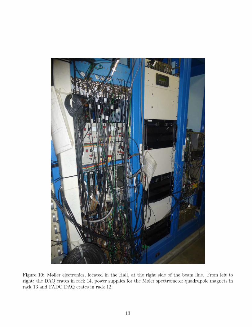
Figure 10: Møller electronics, located in the Hall, at the right side of the beam line. From left toright: the DAQ crates in rack 14, power supplies for the Møler spectrometer quadrupole magnets inrack 13 and FADC DAQ crates in rack 12.
13

Figure 11: The Møller FADC crates.
14

Figure 12: The slow control GUI (Java).
– Detector Settings is used to set up the thresholds, delays etc.
– High Voltage Control for the photomultiplier tubes
– Motor Control to move the collimator
– Target Monitor information on the target position, magnets etc.
High voltage can be changed or turned on/off using the HV GUI window (Fig. 13), where the firsteight channels belong to the calorimeter and the other eight channels belong to the aperture counters.The settings of the CAMAC electronics used to select the trigger and control DAQ are controlledusing the Detector Setting window (Fig. 14):
– Delay line - the delays for the calorimeter and aperture counter signals;
– LedDiscriminator - discriminator thresholds for the calorimeter and the counters
– PLU Module - settings of the logical unit
The collimator width can be changed using Motor Control window (Fig. 15).
4 Operating Procedure
The procedure includes general steps as follows:
• “Non-invasive” preparations - start the appropriate computer processes, turn on the HV andlearn the magnet settings needed;
• “Invasive” preparations: beam tuning with the regular magnet settings, loading the Møllersettings, beam tuning, if neccessary, installing the Møller target;
• Detector check/tuning;
• Measurements;
• Restoring the regular settings.
15
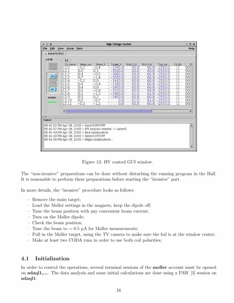
Figure 13: HV control GUI window.
The “non-invasive” preparations can be done without disturbing the running program in the Hall.It is reasonable to perform these preparations before starting the “invasive” part.
In more details, the “invasive” procedure looks as follows:
– Remove the main target;
– Load the Møller settings in the magnets, keep the dipole off;
– Tune the beam position with any convenient beam current;
– Turn on the Møller dipole;
– Check the beam position;
– Tune the beam to ∼ 0.5 µA for Møller measurements;
– Pull in the Møller target, using the TV camera to make sure the foil is at the window center;
– Make at least two CODA runs in order to use both coil polarities;
4.1 Initialization
In order to control the operations, several terminal sessions of the moller account must be openedon adaql1,.... The data analysis and some initial calculations are done using a PAW [3] session onadaql1:
16

Figure 14: Detector setting GUI window.
– Login to adaql1 as moller;– adaql1> cd paw/analysis, start PAW (type paw), select Workstation type 3.
Check that the portserver connections are available:
– Try telnet hatsv5 2003 and telnet hatsv5 2004;– If a connection is refused - clean it up, by connecting telnet hatsv5 as root and typing kill 3
or kill 4, see instructions in ∼adaq/doc/portserver.doc.
Slow control:
– Login to adaql1 as moller;– Start the slow control (see section 3.7);
17

Figure 15: GUI window to control the dipole collimator size (and also the slide, which is not relevanthere).
– Load the regular settings and the appropriate HV.
CODA runs on adaql1:
– Login to adaql1 as moller, make two sessions;
– adaql2> kcoda - clean up the old coda;
– Reset the VME board hallavme5 by: telnet hatsv5 2004, -> reboot;
– adaql2> start coda - start CODA;
– Click Connect and select the configuration beam pol;
– Click Download to download the program into the VME board.
4.2 Initial Beam Tune
Typically, the Møller measurements are taken during the regular Hall A running, when the beam hasbeen tuned for this running. However, the Møller measurements require a different magnetic setting.At least the dipole magnet has to be turned on. This magnet slightly deflects the beam downward.The deflection at the main target could be 2-8 mm, depending on the beam energy. It is, therefore,useful to tune the beam position before the dipole is turned on. It can be done before the magnetsare set to the Møller mode. The requirements for straight beam are:
– On BPM IPM1H01 (in front of the Møller target) |X| < 0.1 mm, |Y | < 0.1 mm.
– On BPM IPM1H04 (downstream of the Møller detector) |X| < 0.1 mm, |Y | < 0.1 mm.
These requirements should be given to MCC.
18

4.3 The Magnet Settings
The proper Møller magnets (quads and dipole) settings for the given beam energy have to be providetto MCC by the Møller polarimeter team.5 The beam must be turned off when the magnets are beingtuned.
4.4 Final Beam Tune
The beam parameters for Møller measurements are:
– beam currents between ∼ 0.5 µA and < 2 µA;
– the beam current should be reduced mainly by closing the “slit” in the injector (not by thelaser attenuator), in order to reduce the effect of current leak-through from the other halls.
4.5 Target Motion
The procedure is as follows:
– Ask the MCC to mask the main target (cryotarget or whatever) motion and remove the maintarget, then ask the MCC to unmask the motion;
– Ask the MCC to mask the Møller target motion;
– Move to target to the position needed (say, 4) using the MEDM screen (see Fig. 2). Check thatthe target is close to the center of the window in the TV camera screen.
4.6 Detector Tuning and Checking
The goal is to check that the detector is working, that the counting rates are normal and that theMøller peaks are located at about ADC channel 300 for all the calorimeter blocks.
A. Data taking with CODA
1. Take a RUN for about 20k events. Let us assume the run number is 9911.
B. Data analysis with PAW
1. PAW> exec run run=9911: build an NTUPLE and attach it to the PAW session;
2. PAW> exec lg spectra icut=60 run=9911: look at the ADC distributions. Thepeaks should be at about ADC channel 300 for all 8 modules. If the peaks are off - try toadjust the HV (do not go beyond 1990V).
C. Check of the background5A reasonable accuracy in the magnets settings is about 1-2%.
19

1. Raise the thresholds to 240 mV of the channels 1 and 2 of the discriminator, using theslow control window (see section 3.7);
2. Take a run of about 20k events, say run=9915;
3. PAW> exec lg spectra icut=60 cut=11 run=9915: look at the ADC distributions.The peaks should be at about ADC channel 300 for all 8 modules. The histograms 9 and10 present the sums of the left and right arms. The histogram 11 (sum of both arms)should contain a clean peak at about channel 600;
4. PAW> exec asymu run=9915: polarization analysis should provide a reasonable num-ber. Check the scaler rates per second. The counting rates in each arm should not exceed600kHz. If they are higher ask the MCC to reduce the beam current.
4.7 Polarization Measurement
1. Take an even (say, 2) number of runs of data, each run of about 20-30 k events (30 k atEbeam < 2 GeV).
2. Analyze the data
1. PAW> exec run run=Run Number and
2. PAW> exec asymu run=Run Number, for each RUN,
4.8 Polarization Measurement with FADC
ROOT[4] based analyzer is used to process data from FADC DAQ. Data analysis is performedon hamoller computer under “a-onl” account. One should go to directory moller\moller fadc-18Feb2011\ and type command:a-onl> source root-setup.shMove into the analysis directory:a-onl> cd onlanaTo replay a new run (< Run Number >) and generate a new .root file:a-onl> analyzerIn analyzer terminal type:ROOT> replay test(< Run Number >)To analyse run (< Nevents > is number of events to analyze, -1 - all events) type:ROOT> t = T (< Run Number >)ROOT> t− > Loop(< Nevents >)Few graphic windows will be pop up and calculated asymmetries are printed in analyzer terminal.
20

5 Safety Assessment
5.1 Magnets
Particular care must be taken in working in the vicinity of the magnetic elements of the polarimeteras they can have large currents running in them. The quadrupole magnets and the leads for the dipolemagnet are protected with Plexiglas shields. Removal of these shields requires following JLab’s “Lockout / Tag out” procedure and ESH&Q rules. Concurrence from the Hall A work Coordinator mustbe obtained before proceeding with such work.
As with all elements of the polarimeter which can affect the beamline, the magnets are controlled byMCC. There is a light panel “MAGNET ON” (see Fig. 16) which indicates the status of the Møller po-larimeter magnets (quadrupole magnets MQM1H02A, MQM1H02, MQO1H03, MQO1H03Aand dipole magnet MMA1H01).The light panel is placed on the top of Møller magnets plasticshielding box and lighting when any one of the Møller magnets is energized.
Figure 16: “MAGNET ON” light panel on the top of the Møller spectrometer shielding guard.
The power supply (62 V, 500 A rating) for the dipole is located in the Beam Switch yard Building(Building 98). The maximum current for the dipole is 450A. The power supplies for quadrupolesMQM1H02, MQO1H03 and MQO1H03A (40 V, 330 A rating) are located in Hall A electronics
21
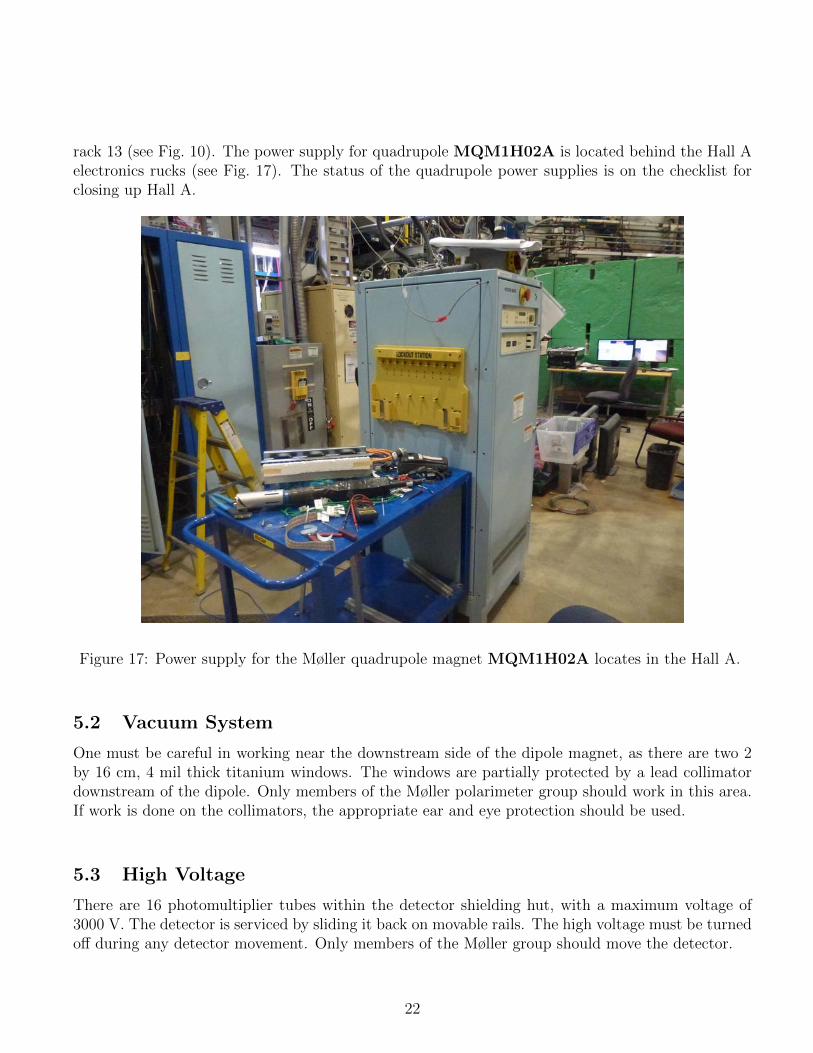
rack 13 (see Fig. 10). The power supply for quadrupole MQM1H02A is located behind the Hall Aelectronics rucks (see Fig. 17). The status of the quadrupole power supplies is on the checklist forclosing up Hall A.
Figure 17: Power supply for the Møller quadrupole magnet MQM1H02A locates in the Hall A.
5.2 Vacuum System
One must be careful in working near the downstream side of the dipole magnet, as there are two 2by 16 cm, 4 mil thick titanium windows. The windows are partially protected by a lead collimatordownstream of the dipole. Only members of the Møller polarimeter group should work in this area.If work is done on the collimators, the appropriate ear and eye protection should be used.
5.3 High Voltage
There are 16 photomultiplier tubes within the detector shielding hut, with a maximum voltage of3000 V. The detector is serviced by sliding it back on movable rails. The high voltage must be turnedoff during any detector movement. Only members of the Møller group should move the detector.
22

5.4 Target
To avoid damage to the Møller target, the target should not be in the beam if the beam current isgreater than 5 µA. The experimenters are responsible for ensuring that the Møller target is removedfrom the beam for regular running and that its position is unmasked.
6 Authorized Personnel
The list of the presently authorized personnel is given in Table 2. Other individuals must notify andreceive permission from the contact person (see Table 2) before adding their names to the above list.
Name Dept. Ext. e-mail CommentJavier Gomez JLab 7498 [email protected] Primary contactOleksandr Glamazdin Kharkov 5441 [email protected] Pomatsalyuk Kharkov 5395 [email protected] Vereshchaka Kharkov 5441 [email protected]
Table 2: Moller Polarimeter: authorized personnel.
References
[1] CODA documentation. WWW page. URL http://coda.jlab.org/.
[2] EPICS Documentation. WWW page. URL http://www.epics.org/. see alsohttp://www.aps.anl.gov/asd/controls/epics/EpicsDocumentation/WWWPages/EpicsDoc.html.
[3] PAW Documentation. WWW page. URL http://wwwasd.web.cern.ch/wwwasd/paw/.
[4] CERN. ROOT Package. URL http://root.cern.ch.
23

By signing this page, you testify that you have read, understand, and agree to abide by the procedurespecified in the above referenced work control document:
Serial Number: ENP-13-29345-OSPTitle: Commssioning of Hall A Moller Polarimeter for 11 GeV
Name Signature Date