performance evaluation ofga and rl based pss of a … design of pss for a single machine connected...
TRANSCRIPT

2013 International Conference on Circuits, Power and Computing Technologies [ICCPCT-2013]
Performance Evaluation ofGA and RL based PSS of a Multi-Machine System
J Abdul Jaleel, Nasar. A, PreethyK Department of Electrical and
Electronics Engineering, Thangal Kunju Musaliar College of Engineering,
Department o{ Electrical and Electronics Engineering, Thangal Kunju Musaliar
Department of Electrical and Electronics Engineering, Thangal Kunju Musaliar
College o{ Engineering,
Kollam - 691 005, Kerala, India. [email protected],
College of Engineering,
Kollam - 691 005, Kerala, In dia. Kollam - 691 005, Kerala, India.
Abstract - One of the main problems that lead to instability in a power system is the low frequency oscillation caused by swinging generator rotor. These oscillations will lead to loss of synchronism, limit the power transfer capability and also lead to the islanding of inter connected power system. So it is very important to damp out these oscillations, power system stabilizer (PSS) is a device which is commonly used for damp out these
oscillations. A power system stabilizer uses angular speed as the input and produce stabilizing signal to damp out these oscillations. The most commonly used power system stabilizer is the conventional power system stabilizer, wh ich is designed by using the theory of phase compensation in the frequency domain and it uses a lead-lag network in its design. This paper focus on the design of PSS for a Single machine connected to infinite bus system (SMlB) and Multi-machine power system having 3 generator and 9 bus system. For optimizing the gain of PSS, Genetic algorithm and Reinforcement learning techniques are used. The simulations are carried out using state space modelling technique.
Keywords - Power system stabilizer, Reinforcement Learning,
Genetic Algorithm, SMlB, MATLAB, Multi-machine power system
I. INTRODUCTION
One of the important aspects in electric power system is the stability. Power system stability can be defined as the ability of a power system to remain in a state of equilibrium under optimal operating condition and regain an acceptable state of equilibrium after disturbance. So a power system should maintain frequency and voltage level in the desired level, under different operating condition such as, sudden increase in load, loss of synchronism or switching out of transmission line. Low frequency oscillations in the power systems are in the order of 0.2 to 3 Hz. When these oscillations arises, there is two possibilities, one is it will continue the oscillations for a long period of time and affect the power transfer capability , secondly, the oscillations will continue to grow and causing the system separation. To enhance system damping, the generators are equipped with PSS that provide stabilizing signals in the excitation system[9]. The most commonly used PSS are conventional PSS, where the gain settings are fixed at certain value, which are determined under particular operating condition. For the optimization of the PSS gain, genetic algorithm and Reinforcement Learning are used. This paper is organized as follows: Section I gives the introduction of power system stabilizer. Section 11 is dealing with the design of conventional power system. In section 111 dicuss, the model of
preethiks [email protected]
single machine and multi-machine system and its modelling equations and the section IV, provides the concepts of genetic algorithm. Section V, discuss the concepts of Reinforcement learning. In section VI, discuss about the results of simulation, and section VII, conc1udes with our observation and future work plan.
11. POWER SYSTEM STABILIZER
The action of a PSS is to extend the angular stability limits of a power system by providing supplemental damping to the oscillation of synchronous machine rotors through the generator excitation. This damping is provided by an electric torque applied to the rotor that is in phase with the speed variation. Once the oscillations are damped, the thermal limit of the tie-lines in the system may then be approached. The most commonly used power system stabilizers are conventional power system stabilizer, which are designed by using the theory of phase compensation techniques. Conventional power system stabilizers (CPSSs) are basically designed on the basis of a linear model for the power system. The power system is first linearized around a specific operating point of the system. Then, assuming that disturbances are small such that the linear model remains valid, the CPSS is designed.
�EI--L..-___ ----'
I' sTI l . sT,
Fig.l. Block Diagram Representation of PSS
The block diagram of the power system stabilizer is as shown in Fig. 1. The stabilizer consist of mainly four blocks, these are PSS gain (kw), Wash out circuits, compensator and limits. Compensator is nothing but a simple lead-lag controller.
Here Kw is the gain, Tw is the washout filter constants, TI, T2 are the lead-lag network time constants.
The form of compensator is given by equation (1) as;
T(s)=Kw(1+sT\)m sTw
........ ( 1) (1+sT2) (1+sTw)
Where m is the number of lead-Iag stages.
978-1-4673-4922-2/13/$31.00 ©2013 IEEE 461
2013 International Conference on Circuits, Power and Computing Technologies [ICCPCT-2013]
III. POWER SYSTEM MODEL
A. SMIB
For this paper a single machine connected to infmite bus (SMIB) is chosen. The general configuration of a SMIB is as shown [I].
Fig.2. Single Machine Connected To Infinite Bus
The state space formulation of SMIB can be expressed as follows:
11 8 = 0101101 · 1 , 1101=-(-K 118-dl101-K M ) M 1 2 q
In the matrix form it can be written as
X(t) = AX(t) + Bu(t) Where
0 010 0 0 -K1 -Do -K2 0 M M M A= -K4 0 -1 1 T�o K3T�o T�o -KAK5 0
-KAK6 -1 T4 TA TA 118 0
1101 0 X = M;/ B = 0
KA MI//) TA
(2)
(3)
(4)
(5)
(6)
(7)
(8)
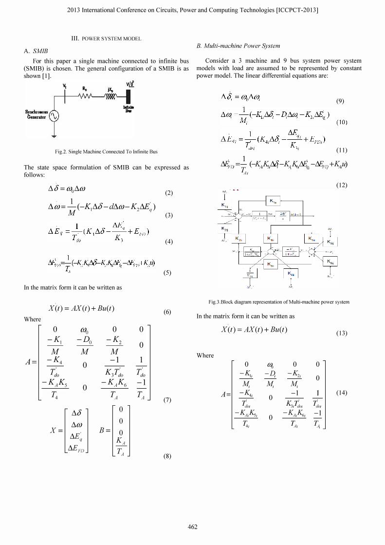
B. Multi-machine Power System
Consider a 3 machine and 9 bus system power system models with load are assumed to be represented by constant power model. The linear differential equations are:
(9)
(11)
, 1 , N!;/) =
T . (-�iK,/�4 -�iIY,/Y';i -N!;/j +�p) Al
(12)
Fig.3.Block diagram representation of Multi-machine power system
In the matrix form it can be written as
X(t) = AX(t) + Bu(t) (13)
Where
0 � 0 0 -K -D -K 1i 1 2; 0 M; M; M;
A= -K -1 (14) 4; 0 t Kr' t dOi 3, dOi dOi
-KA;Ks; 0 -KA;K6; -1
Tt; �; TA,
462

2013 International Conference on Circuits, Power and Computing Technologies [ICCPCT-2013]
/').°i 0
/').OJi 0
X= /').E�i
B= 0 K Ai
/').EFDi TAi
When PSS is installed the A matrix become
-1 K,/doi
0 -�i m
-KAAi �i
-K2iTJiKp �im
With state variable
X=
Mqi /').� /').0),
MjiJ)i
A=
-Kti 0 1
Tdoi Tdoi 0 rq, 0
-�i 0 0 m
-KAfCsi 0 -1 �i �i
-�l'JiKp Kp 0 �im �i
IV. GENETIC ALGORITHM
(15)
0
0
0
KAi �i -1 �i (16)
(17)
Genetic Algorithms (GA) are direct, parallel, stochastic method for global search and optimization, which imitates the evolution of the living beings, described by Charles Darwin. GA are part of the group of Evolutionary Algorithms (EA).Genetic algorithms are search algorithms based on the mechanics of natural selection and natural genetics. They combine survival of fittest among string structures with a structured yet randomized information exchange to form a search algorithm with some of the innovative flair of human search[2]-[6], [lI], [12].
The four most significant differences of GA as compared to other conventional optimization techniques are:
• GAs searches a population of points in parallel, not a single point.
• GAs do not require derivative information or other auxiliary knowledge; only the objective function and corresponding fitness levels influence the directions of search.
• GAs use probabilistic transition rules, not deterministic ones.
• GAs work on an encoding of the parameter set rather than the parameter set itself (except in where real-valued individuals are used).
Genetic operators [12] can he divided into three main categories: Selection, Crossover, and Mutation: I. Selection: Selects the fittest individuals in the current population to he used in generating the next population. 2. Crossover: Causes pairs, or larger groups of individuals to exchange genetic information with one another. 3. Mutation: Causes individual genetic representations to be changed according to some probabilistic rule.
Initializing alt population by randomgen�
Fig.4.Flow chart of GA
yes
Genetic algorithms are more likely to converge to global optima than conventional optimization techniques, since they search from a population of points, and are based on probabilistic transition rules. Conventional optimization techniques are ordinarily based on deterministic hill-climbing methods, which may find local optima. Genetic algorithms can also tolerate discontinuities and noisy function evaluations [3]. Figure 5 shows the flow chart of the execution of GA.
V. REINFORCEMENT LEARNING
Reinforcement Learning techniques are simple iterative algorithms and their control laws are evolved based on observed system response. Reinforcement learning is what to do-how to map situation to action-so as to maximize numerical reward function. Reinforcement learning is defined no by characterizing learning method, but by characterizing learning problem. Any method that weil suited to solve that problem can be considered to a RL method. Basic idea of RL is simply capture the most important aspects of real problem facing learning agent interacting with its environment to achieve a goal. Such an agent must be able to sense the state of the environment to some extent and must be able to take actions that affect the states.
Main sub-elements of a reinforcement learning system: a policy, a reward function, a value function, and, optionally, a model of the environment. A policy defines the learning agent's way of behaving at a given time. A reward function defines the
463

2013 International Conference on Circuits, Power and Computing Technologies [ICCPCT-2013]
goal in a reinforcement learning problem. Reward function indicates what is good in an immediate sense, a value function species what is good in the long run. A reinforcement learning agent's sole objective is to maximize the total reward it receives in the long run. The reward function defines what are the good and bad events for the agent.
Agent
Action
Environment
Fig.5.Reinforcement Learning technique
RL assumes that the environment is a finite set of Markov Processes and described by a set of S and an, agent can choose one action from a finite set of action. At each step ,the agent observes the current state of the environment (s �S) and choose an action a (a �A) that tend to maximize an expected long-term value function. After taking action (a), the agent is given an immediate reward r (r IR), expressing the effectiveness of the action and observing the resulting state of the "environment" s'(s' I S). The goal of RL is to take these experience tuples (s, a, r, s') and learn a mapping from states (or states and actions, depending on the particular algorithm used) to a measure of the long-term value of taking this action, known as the optimal value function. Here Q-Iearning algorithm is used[I]. This approach optimizes an iterative function to gain an optimal action strategy and get a maximal expected discountable long-term value. The Q-Iearning optimal value function (Q-function) is defined as:
Q(s,a) = R(s,s' ,a) + rI pes' / s, a)maxQ(s', a) (18)
Where P represents the probability of applying action in the state s and changing to s. R represents the immediate reward. The Q(s, a) updated according to
(j+l (Sk' ak) =(j(sk,ak) + a[ R(Sk'Sk+l4) + rma�(sk+l'a) -(j(sk,ak)] (19)
(20) The optimum Q function is iteratively approximated to the
Q value. rr is defined as a greedy action -selected policy, which represents that the agent selects an action with the largest Q-value from a given state.
rr = arg max* Qk (s, a) (21) The function of PSS is to damp the low frequency
oscillation of power system. So in RL based PSS angular frequency deviation (�w) as the states, PSS gain (Kw) as the action ,which we want to optimize.
VI. SIMULATION RESULT
A. SMIB
Simulations are carried as a MATLAB program on M-file. First obtained the response of the SMIB with-out PSS using program and the response obtained for a step disturbance is shown in fig 6. Then a CPSS is designed and its response is also obtained on M-fiIe and it is shown in figure 7. Then GA and RL optimization technique is applied and obtained the optimum value PSS gain. The program results show the effectiveness of GA and RL based PSS as compared to conventional PSS. Fig 8 and Fig 9 shows the response with GA and RL optimization techniques.
1 -- -
Fig.6. Response without PSS "'o�r----p---------p���--�====���
�� Fig.7. Response With CPSS
. �
I
1-:::] -- ,Q..I;,IIIISS
Co
Fig.8. Response with CPSS and GA-PSS
464

2013 International Conference on Circuits, Power and Computing Technologies [ICCPCT-2013]
-0 08 0L'--�----=---�-�--�---=-------! Time (seconds)
Fig.9.Response with CPSS and RL-PSS
B.MULTlMACHINE POWER SYSTEM Simulations are carried as a MATLAB pro gram on M-fiIe.
First obtained the response of the mult-imachine power system with-out PSS using pro gram and it is shown in figure 10. Then a CPSS is designed and its response is also obtained on M-fiIe and it is shown in fig 11. Then GA and RL optimization technique is applied and obtained the optimum value of the PSS gain. The program results shows the effectiveness of GA and RL based PSS as compared to conventional PSS. Fig12 and Fig 13 shows the response of PSS with GA and RL.
m&chine 1
TIfTle (seconds) machine 2
L� ' . .0 .. .. 0'1 o 1 2 3
TIITlC' (seconds) machine 3
Time (seconds)
Fig. 10. Response of multi-machine without PSS
machite 1 [��� :�-=--=-= -=-------"==
1 -�::::.::;; I
o 5 Tme (seconds)
mIlchine 2
10 15
Ut0��, • ,I-�:'::;;I I 0 1 2 J " 5 6
Tme (seconds) ITlIIchite3
0 1
L:� . I-�:·::;; I o 0.5 1 1.S 2 2..5 3 3.5
Tme (seconds)
Fig.ll.Response of multi-machine system without PSS and CPSS
Imachine 1 5 o·05 I------,---------,---;=====:::;l il -- Wo,u! pss .� -- Wilh CPSS " ""'"'�oIpo;l-"'rl_>.:::::r=".=-�---_i -- Wilh GA-PSS
10 15 Tone (s.conds)
machine 2 5 0.1 1-----.---,-------,----,---;=====:::;l il -- Wo,u! pss .� -- Woh CPSS
� �$>+ ....... _e=..",,�------__1 -- Wilh GA-PSS c . o
I .0.1 L-__ --"-___ "---__ ----' ___ ....L ___ L-__ --' o
Tone (s.conds) mach.ine3
5 0.11-----.---,-------,----,---;=====:::;l il -- Wo,u! pss .� -- Woh CPSS " >- -- Wilh GA-PSS u c . o
I .0.1 '--__ --'-___ "-__ ----L ___ ....I.-___ '--__ --' o � U
Tone (seconds) Fig.12.Response of power system model with GA-PSS
machine 1 .: O . 05 i------.--------r-;:======;_J � -- Without PSS
�t7f"""'=_r-"-::-r'=.=.=-'���-__I -- W,th CPSS
Time (seconds) machine 2
10
�}/�O�� : : ! 0 1 2 3 4 Time (seconds) machine 3
iJE= : : o 0.5 1 1.5 2 2.5
Time (seconds)
-- RL-PSS
15
I��:�::"I 6
I��:\�:"I 3.5 4
Figl3.Response with CPSS and RL-PSS
VII. CONCLUSION
Application of GA and RL based power system stabilizer to a Multi-machine power system and a SMIB for a step input disturbance shows its effectiveness in enhancing the damping characteristics. As compared to conventional power system stabilizer the overshoots and settling time are very less for GA and RL based PSS. But one of the disadvantages of CPSS is that most of them are designed on the basis of linear model and they give a specific operation for a particular operating point. This drawback of CPSS is compensated by GA and RL based PSS. The simulation are carried out as a MA TLAB program on M-fiIe, the advantage as compared MATLAB Simulink is that fast convergence and easiness in finding the error. In our future scope, we will extend the study to a real time grid such as Kerala Grid.
465

2013 International Conference on Circuits, Power and Computing Technologies [ICCPCT-2013]
ACKNOWLEDGMENT
The authors would like to thank the management, and Faculty Members, of Oepartment of Electrical and Electronics Engineering, TKM College of Engineering, Kollam, for many insightful discussions and the facilities extended to us for completing the task.
APPENDIX A. SMIB Machine parameters:
H=0 . 5, T�o =5 . 5sec, Vrej = 1 ,D=O , ((Jo =377, K1 = 3.7585
K2 = 3.6816, K3 = 0.2162, K4 = 2.6582, K5 = 0.0544,
K6 = 0.3616
Exciter parameter: TA =0.2sec , K A =50 ,
PSS parameter: Kw =0 . 5 , � =0 . 5 ,1; =0 . 1 B. Multi-machine
Machine parameters:
D1 = D2 = D3 = 0, H1 = 23.46, H2 = 6.4, H3 = 3, Tdo] = 8.96,
Tdo2 = 6, Tdo3 =5.82 K1 =3.7585, K2 =3.6816, K3 =0.2162 ,K4 = 2.6582, K5 = 0.0544, K6 = 0.3616
Exciter parameter: KA1 = KA2 = KA3 = 200
TAl = TA2 = TA3 = 0.05
PSS parameter: Kp = 5, 11 = 0.078, T2 = 0.026
REFERENCES
[I] Tao YU and Wei-Guo ZHEN, "A Reinforcement Learning approach to power system stabilizer", 978-1-4244-4241-6109, IEEE, 2009
[2] L.Davis,Handbook of Genetic Algorithms.New York: Van Nostrand, 1991 [3] M A .Abido and Y L.Abdel-magid.," Optimal multiobjective design of
robust power system stabilizer using genetic Algorithm" IEEE transactions on Aerospace and Electronic Systems, Vo1.32,No. 3, July 1996.
[4] M A .Abido and Y L.Abdel-magid, "Hybridizing rule based power system stabilizers with genectic algorithm" IEEE transactions on Power systems ,Vol,No 2,may 1999.
[5] M A .Abido and Y L.Abdel-magid. "Simultaneous stabilization of multimachine power system via genetic algorithm" IEEE Transactions on Power systems ,Vo1 14 ,Novenber 1999.
[6] M. A Pai, Energy Function Analysis for Power System Stability. Norwell,MA: Kluwer, 1989.
[7] M.Ravindra Babu and S V Padmavathi. Design of PSS3B for multimachine using GA"VoI2,lssue 3,May-June 2012,pp 1265-1271.
[8] P.M. Anderson and AA Fouad, Power System Control and Stability(Iowa: Iowa State university Press, 1977).
[9] Prabha Kundur, Power System Stability and Control(Tata Mc Graw-Hill Edition)
[10] Rashidi, M.; Rashidi, F.; Monavar, H.; Tuning of power system stabilizers via genetic algorithm for stabilization of power system, Systems, Man and Cybernetics, 2003. IEEE International Conference on Volume 5, 5-8 Oct. 2003,pp.4649 - 4654 vo1.5.
[ll] S.Ehsan Razavi and Abdollah Babaei,"New technique to improve power system stabilizer via genetic algorithm"jounal of American Science,20 11
[12] Seyyed Hossein and Reza rahnavard" Application of genetic algorithm to design PID controller for power system Stabilization"
[13] Shoorangiz Shams Shamsabad and Mehdi Nikazad" Multi-machine power system stabilizer adjustment using genetic Algorithm"ISSN:0974-6846. genetic local search technique
[14] Tsong-Liang huang and Chih-Han Chang." Design of Sliding mode power system stabilizer via genetic algorithm"proceeding 2003,1EEE International Symposium,july 16-20.
USA in 2006.
BIOGRAPHY
1 Abdul Jaleel. J received the Bachelor degree in Electrical Engineering from University of Kerala, India in 1994. He received the M.Tech degree in Energetics from Regional Engineering College Calicut, Kerala, India in 2002, and PhO from WIU,
He joined the EEE department of TKM College of Engineering as faculty member in 1990. He was with Saudi Aramco in 1996 to 1998 and worked in the field of power generation, transmission, distribution and instrumentation in the Oil and Gas sector of Saudi Arabia. He was with Water Supply department of Sultanate of Oman in 1985 to 1986 and worked with the maintenance of Submersible bore-well pumps and power supplies. He was with Saudi Electricity Company in 1979 to 1985 and worked in the Generation, Transmission and distribution fields. He worked with project management, Quality Management and he is a certified Value Engineer and Auditor for QMS. He is a consultant for Oztern Microsoft, Technopark, Kerala and Consultant for Educational Projects of KISAT and MARK Research and Education Foundation.
Currently he is a P.G. Coordinator of M. Tech Programme in the TKM College of Engineering under University of Kerala and DC member VIT University, Research Supervisor in Anna University & Karppagam University. . His main areas of research are power system control & optimization, power system reliability, voItage stability, computer aided design and analysis.
Preethy.K received B.Tech in Electrical and Electronics Engineering from Perumon College of Engineering Kollam. Currently she is doing M.Tech Industrial Instrumentation and Control at TKM college of Engineering.
466