performance evaluation of small hydro power plants
TRANSCRIPT

8/20/2019 Performance Evaluation of Small Hydro Power Plants
http://slidepdf.com/reader/full/performance-evaluation-of-small-hydro-power-plants 1/69
STANDARDS/MANUALS/GUIDELINES FORSMALL HYDRO DEVELOPMENT
1.10General–Performance evaluation of small hydro power plants
Sponsor:
Ministry of New and Renewable EnergyGovt. of India
Lead Organization:
Alternate Hydro Energy CenterIndian Institute of Technology Roorkee
October 2012

8/20/2019 Performance Evaluation of Small Hydro Power Plants
http://slidepdf.com/reader/full/performance-evaluation-of-small-hydro-power-plants 2/69
Contact:
Dr Arun Kumar
Alternate Hydro Energy Centre,
Indian Institute of Technology Roorkee,
Roorkee - 247 667, Uttarakhand, India
Phone : Off.(+91 1332) 285821, 285167
Fax : (+91 1332) 273517, 273560E-mail : [email protected], [email protected]
DISCLAIMER
The data, information, drawings, charts used in this standard/manual/guideline has been
drawn and also obtained from different sources. Every care has been taken to ensure that the
data is correct, consistent and complete as far as possible.
The constraints of time and resources available to this nature of assignment, however do not
preclude the possibility of errors, omissions etc. in the data and consequently in the report
preparation.
Use of the contents of this standard/manual/guideline is voluntarily and can be used freely
with the request that a reference may be made as follows:
AHEC-IITR, “1.10 General – Performance Evaluation of Small Hydro Power Plants”,
standard/manual/guideline with support from Ministry of New and Renewable Energy,
Roorkee, Oct. 2012.

8/20/2019 Performance Evaluation of Small Hydro Power Plants
http://slidepdf.com/reader/full/performance-evaluation-of-small-hydro-power-plants 3/69
PREAMBLE
There are series of standards, guidelines and manuals on electrical, electromechanical
aspects of moving machines and hydro power from Bureau of Indian Standards (BIS), Rural
Electrification Corporation Ltd (REC), Central Electricity Authority (CEA), Central Board of
Irrigation & Power (CBIP), International Electromechanical Commission (IEC), InternationalElectrical and Electronics Engineers (IEEE), American Society of Mechanical Engineers
(ASME) and others. Most of these have been developed keeping in view the large water
resources/ hydropower projects. Use of the standards/guidelines/manuals is voluntary at the
moment. Small scale hydropower projects are to be developed in a cost effective manner with
quality and reliability. Therefore a need to develop and make available the standards and
guidelines specifically developed for small scale projects was felt.
Alternate Hydro Energy Centre, Indian Institute of Technology, Roorkee initiated an
exercise of developing series of standards/guidelines/manuals specifically for small scale
hydropower projects with the sponsorship of Ministry of New and Renewable Energy,
Government of India in 2006. The available relevant standards / guidelines / manuals were
revisited to adapt suitably for small scale hydro projects. These have been prepared by the
experts in respective fields. Wide consultations were held with all stake holders covering
government agencies, government and private developers, equipment manufacturers,
consultants, financial institutions, regulators and others through web, mail and meetings.
After taking into consideration the comments received and discussions held with the lead
experts, the series of standards/guidelines/manuals are prepared and presented in this
publication.
The experts have drawn some text and figures from existing standards, manuals,
publications and reports. Attempts have been made to give suitable reference and credit.
However, the possibility of some omission due to oversight cannot be ruled out. These can be
incorporated in our subsequent editions.
This series of standards / manuals / guidelines are the first edition. We request users to
send their views / comments on the contents and utilization to enable us to review for further
upgradation.

8/20/2019 Performance Evaluation of Small Hydro Power Plants
http://slidepdf.com/reader/full/performance-evaluation-of-small-hydro-power-plants 4/69
Standards/ Manuals/Guidelines series for Small Hydropower Development
General
1.1 Small hydropower definitions and glossary of terms, list and scope of different
Indian and international standards/guidelines/manuals
1.2
Part I
Planning of the projects on existing dams, Barrages, Weirs
1.2
Part II
Planning of the Projects on Canal falls and Lock Structures.
1.2
Part III
Planning of the Run-of-River Projects
1.3 Project hydrology and installed capacity
1.4 Reports preparation: reconnaissance, pre-feasibility, feasibility, detailed project
report, as built report
1.5 Project cost estimation
1.6 Economic & Financial Analysis and Tariff Determination
1.7 Model Contract for Execution and Supplies of Civil and E&M Works
1.8 Project Management of Small Hydroelectric Projects1.9 Environment Impact Assessment
1.10 Performance evaluation of Small Hydro Power plants
1.11 Renovation, modernization and uprating
1.12 Site Investigations
Civil works
2.1 Layouts of SHP projects
2.2 Hydraulic design
2.3 Structural design
2.4 Maintenance of civil works (including hydro-mechanical)
2.5 Technical specifications for Hydro Mechanical Works
Electro Mechanical works3.1 Selection of Turbine and Governing System
3.2 Selection of Generators and Excitation Systems
3.3 Design of Switchyard and Selection of Equipment, Main SLD and Layout
3.4 Monitoring, control, protection and automation
3.5 Design of Auxiliary Systems and Selection of Equipments
3.6 Technical Specifications for Procurement of Generating Equipment
3.7 Technical Specifications for Procurement of Auxiliaries
3.8 Technical Specifications for Procurement and Installation of Switchyard
Equipment
3.9 Technical Specifications for monitoring, control and protection
3.10 Power Evacuation and Inter connection with Grid
3.11 operation and maintenance of power plant
3.12 Erection Testing and Commissioning

8/20/2019 Performance Evaluation of Small Hydro Power Plants
http://slidepdf.com/reader/full/performance-evaluation-of-small-hydro-power-plants 5/69
PERSONS INVOLVED
1. Dr Arun Kumar, CSO & Principal Investigator, AHEC, IIT, Roorkee
2. Dr S K Singal, SSO & Investigator, AHEC, IIT, Roorkee
Drafting Group
1. Prof. H.K.Verma, IIT, Roorkee
Consultation Group
2. Dr Arun Kumar,AHEC,IIT, Roorkee
3. Dr S K Singal,AHEC,IIT, Roorkee
4. Mr. S.K.Tyagi, Consultant, AHEC, IIT, Roorkee
5. Mr. A.K.Chopra, MNRE,GOI, New Delhi
6. Mr. A.K.Singh, UJVNL, Dehradun
7. Mr. P.K.Singhal, UPJVNL, Lucknow8. Mr. Pankaj Saxena, UPJVNL, Lucknow
9. Mr. Varshney, THDC, Rishikesh
10. Mr. V.K.Sharma, THDC, Rishikesh
11. Mr. U Ukhal, HPPCL, Himachal Pradesh
12. Mr. B.S.Saini, Gita Flopumps India Ltd.,Saharanpur
13. Mr..S.S.Sidhu, HPP India Pvt. Ltd, Noida
14. Mr. K.C.Arora, Pentaflo Hydro power Ltd
15. Mr. P.K. Malohtra, Pentaflo Hydro power Ltd
16. Mr. Sanjeev Handu, Andriz Hydro power Ltd.
17. Mr. Vishnupad Saha, Andriz Hydro power Ltd.
18. Mr. Dinesh Rajput, Andriz Hydro power Ltd.
19. Mr. Pradeep Dube, Tanushree Hydropower Consultants, Noida20. Mr. H.M.Sharma, Jyoti Ltd.,Vadodra
21. Mr. Viral Mahida, Jyoti Ltd.,Vadodra
22. Mr. Nishant Saha, Jyoti Ltd.,Vadodra
8/20/2019 Performance Evaluation of Small Hydro Power Plants
http://slidepdf.com/reader/full/performance-evaluation-of-small-hydro-power-plants 6/69
CONTENTS
ITEMS PAGE NO
Guidelines for Performance Evaluation of Small Hydro Power Plants
1.0 Objective 1
2.0 Introduction 1
3.0 Scope of Performance Evaluation 1
4.0 References 2
5.0 Visual Inspection 3
6.0 Functional Checks 4
7.0 Measurements and Tests 4
7.1 Error Test on Measuring Instruments 4
7.2 Operational Tests on Protective Relays 47.3 Vibration Measurements 5
7.4 Sound Level Measurements 5
7.5 Load Rejection Test 5
7.6 Maximum Power Output Test 5
7.7 Unit Efficiency Test 5
7.8 Methods of Unit Efficiency Measurement 6
7.9 Measurement of Absolute Discharge 7
7.10 Measurement of Net Head 7
7.11 Measurement of Electrical Power Output 12
7.12 Calculation of Unit Efficiency (Discharge Head Method) 13
7.13 Calculation of Weighted Efficiency 18
7.14 Index Test 19
8.0 Methodology of Performance Evaluation 20
9.0 Provisions to Facilitate Performance Testing 20
9.1 General Guidelines 21
9.2 Provisions for Pressure Measurement 21
9.3 Provisions for Free Water Level Measurement 25
9.4 Provisions for Absolute-Discharge Measurement in General 25
9.5 Provisions for Absolute-Discharge Measurement by Current
Meter Method
26
9.6 Provisions for Absolute-Discharge Measurement using Weir 31
9.7 Provisions for Absolute-Discharge Measurement by Ultrasonic(Acoustic) Methods
34
9.8 Provisions for Relative-Discharge Measurement 42
9.9 Provisions for Electrical Power Measurement 48
8/20/2019 Performance Evaluation of Small Hydro Power Plants
http://slidepdf.com/reader/full/performance-evaluation-of-small-hydro-power-plants 7/69
LIST OF TABLES
FIGURE NO. TITLE PAGE NO.
1. Averages of the Readings Taken for Efficiency Test of
Kaplan Turbine
14
2. Unit Efficiency Calculations for Kaplan Turbine 143. Averages of the Readings Taken for Francis Turbine 16
4. Unit Efficiency Calculations for Francis Turbine 16
5. Averages of the Readings Taken for Pelton Turbine 17
6. Unit Efficiency Calculations for Pelton turbine 18
7. Methods for measurements differential pressure 19
LIST OF FIGURES
FIGURE NO. TITLE PAGE NO.
1. Low-head machine, differential pressure transducer 9
2. Low / medium head machine, separate pressure transducers 103. Low/medium head machine, level sensors 10
4. Vertical-axis Pelton turbine, pressure transducer at inlet 11
5. Horizontal-axis Pelton turbine, pressure transducer at inlet 12
6. Load-Efficiency Curve of the Generating Unit with Kaplan
Turbine
15
7. Load-Efficiency Curve of the Generating Unit with Francis
Turbine
17
8. Load-Efficiency Curve of the Generating Unit with Pelton
turbine
18
9. Example of pressure taps 23
10. Pressure taps connected through separate connecting pips to
box-type manifold
24
11. Pressure taps connected through ring-type manifold to
pressure gauge
24
12. Details of measuring well 26
13. Temporary nozzle or bell-mouth placed in the intake of a
low head turbine
28
14. Means for stabilizing flow in an open channel 29
15. Single vertical row of current meters fixed on a travelling
winch
30
16. Frame supporting two rows of current meters moved up and
down by a hoist
30
17(a). Frame lowered to submerge PCMs into water 3117(b) Frame raised to pull PCMs out of water 31
18. Sketch of a rectangular sharp-crested weir 32
19. Locations of transducers for discharge measurement with
UTTF
36
20. Typical arrangement of transducers in a circular conduit 36
21. Locations for measurement of dimension D 37
22. Measurement of discharge with DT-UTTF 39

8/20/2019 Performance Evaluation of Small Hydro Power Plants
http://slidepdf.com/reader/full/performance-evaluation-of-small-hydro-power-plants 8/69
TABLE NO. TITLE PAGE NO.
23. ADCP Trolley 40
24. Guide rail fixed to the channel wall for guiding movement
of ADCP trolley
41
25. Maneuvering ADCP trolley movement on the guide rail 41
26. Maneuvering V-ADCP from channel banks 4227. Location of pressure taps in steel spiral case 44
28. Illustration of pressure taps in vertical steel spiral case 44
29. Location of pressure taps in concrete semi-spiral case 45
30. Upward slopping pipes and valves for purging 46
31 Location of taps in bulb turbine 47
32. Acoustic method of discharge measurement - Single path
system
48
33. Acoustic method of discharge measurement - Double plane
single path system
48
34. A Sample of TTB 49
35. TTB (shown with cover in place) fitted on the front of a
control panel
50
36. Reference meter connected at TTB without opening the
control panel
50
LIST OF ANNEXURE
ANNEXURE
NO.
TITLE PAGE NO.
1. Format of Power Station data to be supplied by Owner 51
2. Format of Generation data to be Supplied by Owner 61

8/20/2019 Performance Evaluation of Small Hydro Power Plants
http://slidepdf.com/reader/full/performance-evaluation-of-small-hydro-power-plants 9/69
AHEC-IITR/MNRE/SHP Standards/ General - Performance Evaluation of Small Hydro Power Plants 1
PERFORMANCE EVALUATION OF SMALL HYDRO POWER
PLANTS
1.0 OBJECTIVE
Ministry of New and Renewable Energy (MNRE), Government of India (GOI) is
giving high priority to quality and reliability of small hydro power (SHP) projects. Adoptingquality standards is extremely important not only for ensuring a long life of small
hydropower projects but also for their overall economic viability and optimum utilization of
water discharge and head. With the introduction of performance evaluation of SHP stations as
a mandatory requirement in 2003 for receiving subsidy from MNRE, all SHP projects in
India are required to follow Indian / International standards in respect of construction,
equipment and meeting the requirements in terms of specifications as well as performance
parameters.
These guidelines have been prepared for the benefit of developers, designers and
consultants, equipment manufacturers and owners of SHP projects as well as the performance
evaluators of SHP plants, so that the ultimate purpose of performance evaluation stated in the
preceding paragraph can be fulfilled effectively.
2.0 INTRODUCTION
Performance evaluation of a SHP plant/station includes broadly the following:
(a) Inspection and qualitative checks to confirm that all parts, systems and auxiliaries in
the power station are performing their assigned functions correctly.
(b) Measurement and tests to confirm that the generating units are operating satisfactorily
and efficiently, their operating parameters are within reasonable limits and the errors
of protective relays and measuring instruments are within specified limits.
3.0 SCOPE OF PERFORMANCE EVALUATION
The overall scope of performance evaluation is divided below in 3 parts:
(a) Visual Inspection
(i) General inspection
(ii) Inspection of civil works including water conductor system
(iii) Inspection of electrical and mechanical works and equipment
(iv) Inspection of outdoor switchyard
(b) Functional Checks
(i) Functional checks on simple devices.
(ii) Operational checks on control and regulating devices /systems.
(c) Measurements and Tests
(i) Error test on measuring instruments
(ii) Operational tests on protective relays
(iii) Vibration measurements
(iv) Sound level measurements
8/20/2019 Performance Evaluation of Small Hydro Power Plants
http://slidepdf.com/reader/full/performance-evaluation-of-small-hydro-power-plants 10/69
AHEC-IITR/MNRE/SHP Standards/ General - Performance Evaluation of Small Hydro Power Plants 2
(v) Load rejection test
(vi) Maximum power output test
(vii) Unit efficiency test
(viii) Index test
Performance evaluation is carried out in three stages: first of all the visual inspection,
then the various functional checks and finally the measurements and tests.
It should be noted that the measurements and tests mentioned here are carried out
subject to the technical feasibility and availability of provisions for the same in the power
station. Furthermore, detailed diagnostic investigations on any faulty component/system are
kept outside the scope of performance evaluation.
4.0 REFERENCES
RELEVANT CODES AND STANDARDS
Some Indian/ International standards, guidelines and codes of relevant to the subject
are listed below, which may be referred to for getting more details where needed:
R1 IEC-60041-1991 Field Acceptance Tests to Determine the
Hydraulic Performance of Turbines, Storage
Pumps and Pump Turbines (adopted by Bureau
of Indian Standards as IS/IEC-41)
R2 IEC-61116-1992 Electromechanical Equipment Guide for Small
Hydroelectric Installations
R3 IEC-62006-2010 Hydraulic Machines - Acceptance Tests of Small
Hydroelectric Installations
R4 IEC-60545-1976 Guide for Commissioning, Operation and
Maintenance of Hydraulic Turbines
R5 IS-12800-1991 Guidelines for Selection of Hydraulic Turbine:
Preliminary Dimensioning and Layout of
Surface Hydroelectric Power Houses, Part 3:
Small, Mini and Micro Hydroelectric Power
Houses
R6 IEC-60308-1970 Testing of Speed of Governing Systems for
Hydraulic Turbines
R7 IEEE-421-1972 Criteria and Definitions for Excitation Systems
for Synchronous Machines
R8 IEEE-421A-1978 IEEE Guide for Identification, Testing and
Evaluation of the Dynamic Performance of
Excitation SystemR9 ASME PTC-29-2005 Performance Test Code for Speed-Governing
Systems for Hydraulic Turbine-Generator Units
R10 IEC-60034-1-2004 Rotating Electrical Machines – Part 1: Rating
and Performance
R11 IS-4722-2001 Rotating Electrical Machines
R12 IS-3231-1-1965 Electrical Relays for Power System Protection –
Part 1: General Requirements
R13. IS-8686-1977 Static Protective Relays
8/20/2019 Performance Evaluation of Small Hydro Power Plants
http://slidepdf.com/reader/full/performance-evaluation-of-small-hydro-power-plants 11/69
AHEC-IITR/MNRE/SHP Standards/ General - Performance Evaluation of Small Hydro Power Plants 3
R14 IEC-60255-6-1988 Electrical Relays - Part 6: Measuring Relays and
Protection Equipment
R15 IS-11726/ISO-2954 (1975) Requirements for Instruments for Measuring
Vibration Severity of Rotating and Reciprocating
Machines
R16 ISO-10816-1-1995 Mechanical Vibration – Evaluation of Machine
Vibration by Measurements on Non-RotatingParts – Part 1: General Guidelines
R17 IS-11727(1985-Reaffirmed
1996) Measurement and Evaluation of Vibration
Severity in Situ of Large Rotating Machines with
Speed Range from 10 to200 rev/s
R18 . ISO-1680-1986 Acoustics – Test Code for the Measurement of
Airborne Noise Emitted by Rotating Electrical
Machinery
R19 . ISO-2954-1975 Mechanical Vibration of Rotating and
Reciprocating Machinery Requirements for
Instruments for Measuring Vibration Severity
R20 IEC-60034-9-2003 Rotating Electrical Machines - Part 9: Noise
LimitsR21 IS-2705 (1992, Reaffirmed
1997) Current Transformers
R22 IS-3156-1992, Reaffirmed
1997) Voltage Transformers
R23 IEC-61362-1998 Guide to Specification of Hydraulic Turbine
Control Systems
R24 IS-2026-1997 Power Transformers
R25 AHEC-2009 Performance Testing of SHP stations; A guide
for Developers, Manufacturers and Consultants,
AHEC IIT Roorkee Dec 2009
Abbreviations:
ASME : American Society of Mechanical Engineers
AHEC, IITR : Alternate Hydro Energy Centre, Indian Institute of Technology, Roorkee
IEC : International Electro-technical Commission
IEEE : Institute of Electrical & Electronic Engineers
IS : Indian Standard
ISO : International Organization for Standardisation
5.0 VISUAL INSPECTION
In the first stage of performance evaluation, a visual inspection of each and every part
and subsystem may be carried out while the power station is running, and any shortcomingsshould be recorded. The following parts / subsystems may be included in the inspection:
i. Access to power house, intake works, penstock, power channel, headrace channel,
tailrace channel etc. (as applicable).
ii. Communication facilities and general facilities available in the power station.
iii. Safety measures and warnings.
iv. General upkeep, operation and maintenance of the power station.

8/20/2019 Performance Evaluation of Small Hydro Power Plants
http://slidepdf.com/reader/full/performance-evaluation-of-small-hydro-power-plants 12/69
AHEC-IITR/MNRE/SHP Standards/ General - Performance Evaluation of Small Hydro Power Plants 4
v. Complete water conductor system, starting from water intake to the tailrace
discharging into main stream of water.
vi. Complete civil construction works, including intake works, power house building,
diversion / bypass works etc.
vii. Generating units, their ratings, controls etc.
viii. Control room, switchgear room, battery room, machine hall etc.
ix. Station auxiliariesx. Switchyard
xi. Power evacuation arrangement.
6.0 FUNCTIONAL CHECKS
In the second stage of performance evaluation, necessary qualitative checks may be
carried out with an objective of verifying the operation / functioning of the following
components / subsystems and shortcomings / defects, if any, should be recorded:
i. Control Panels: Functional checks on external accessories (lamps, push buttons,
switches, digital indicators, buzzers, hooters etc.) and internal accessories (panel
lights, panel light switches, space heaters, thermostats etc.).ii. Fault / Status Annunciators: Component check, test, accept and reset functions.
iii. Circuit Breakers: Trip and close functions.
iv. Master / Trip / Auxiliary Relays: Operate and reset functions.
v. Control / Regulating Devices: Flow / head regulating devices, excitation voltage
control, speed governor control, power factor control, parallel operation of
generating units, manual start / stop operations, manual / auto synchronization,
local / remote control of transformer tap changer, etc.
7.0 MEASUREMENTS AND TESTS
The following measurements and tests are recommended in the third and final stage of
performance evaluation:
7.1 Error Test on Measuring Instruments
All electrical panel meters (analog / digital ammeters, voltmeters, kilowatt-, power
factor, meters, energy meters, frequency meters and digital multi-function meters) are
subjected to a limited error check. The readings of these meters at the respective operating
points are compared against a portable reference meter to measure their errors at the current
(prevailing) operating points. If a meter is found to have an error beyond its accuracy class,
its recalibration or replacement should be recommended.
A similar check is carried out on speed indicator. Comparison may be made against a reference frequency meter because of the higher resolution and accuracy of reference
frequency meters.
7.2 Operational Tests on Protective Relays
A portable secondary injection test set is used to test all the measuring relays or
different relay functions of multi-function digital relays as per relevant standards. Normally it
is considered sufficient to carry out operating-value and operating-time tests (the latter for
8/20/2019 Performance Evaluation of Small Hydro Power Plants
http://slidepdf.com/reader/full/performance-evaluation-of-small-hydro-power-plants 13/69
AHEC-IITR/MNRE/SHP Standards/ General - Performance Evaluation of Small Hydro Power Plants 5
time delay relays and delay elements only) at the current (prevailing) relay settings. In case of
the doubtful working of a relay, a more detailed secondary injection test may be conducted.
It may be sufficient to test the management relays for their measurement functions only.
7.3 Vibration Measurements
Vibrations are measured with the help of a vibration meter at each bearing of the
generating units on no-load condition as well as full-load condition. Both rms displacement
and rms velocity of the vibrations in the frequency band of the 1 Hz to 1 kHz are measured, if
possible at four mutually perpendicular locations on the bearing, and both along axial and
radial directions. Excessive vibrations, if any, should be brought to the notice of the power
station owner.
7.4 Sound Level Measurements
Sound level is measured with the help of a sound level meter in “weighting factor A”
mode near the machines at no-load conditions. Readings are taken 1 m away from the surface
of generator, turbine, flywheel and gear box (as applicable) at right angle to the machineshaft, both on upstream and downstream sides of the machine. A maximum sound level upto
85 dB is generally desirable and a level of 90 dB is considered acceptable. Sound levels
beyond 90 dB will cause discomfort to the operation and maintenance (O&M) staff working
close to the machine, while a continuous exposure to sound levels above 95 dB can seriously
affect their working efficiency and even cause deafness in them.
7.5 Load Rejection Test
The generating unit under test is initially loaded to its rated value and its speed is
noted down. The maximum sound level near the machine is also recorded on the basis of
sound level test (Section 7.4). The load on the machine is then suddenly rejected using the
emergency shutdown push-button switch and the peak values of the speed and sound level (at
the same point) attained consequently are noted. The maximum rise in the speed should be
within the run-away speed of the generator as specified by its manufacturer.
7.6 Maximum Power Output Test
The test is conducted to check whether the maximum electrical power output actually
available from the generating unit matches with the value specified by the manufacturer. As
far as possible, the test is conducted at the rated head or at the head / discharge specified for
maximum output of the generating unit.
7.7 Unit Efficiency Test
The test of efficiency of the complete generating units is the most difficult, expensive
and time consuming part of the performance evaluation exercise. Therefore, it may be
sufficient to test only one generating unit in the SHP station if there are more than one
identical units in the same power station.
The mandate of various standards on carrying out the efficiency test on the turbine/
generating unit of SHP plants is explained briefly below:
8/20/2019 Performance Evaluation of Small Hydro Power Plants
http://slidepdf.com/reader/full/performance-evaluation-of-small-hydro-power-plants 14/69
AHEC-IITR/MNRE/SHP Standards/ General - Performance Evaluation of Small Hydro Power Plants 6
(a) IEC-60041
IEC-60041 (1991): which has an apparent focus on large machines, does not make an
explicit mention of small hydroelectric installations. However, it leaves the decision of
conducting efficiency test to the parties concerned by stating that “the decision to perform
field acceptance tests including the definition of their scope is the subject of an agreement
between the purchaser and the supplier of the machine”.
(b) IEC-61116
IEC-61116 (1992): which “applies to hydroelectric installations with units having
power outputs less than 5 MW and turbines with nominal runner diameters less than 3 m”,
hints that the efficiency value/test may not be covered under guarantees in the following
cases:
(1) When the efficiency value is not of real use as the available water flow greatly
exceeds the useable flow.
(2) When it is technically difficult or prohibitively expensive to carry out the test.
(c) IEC-62006
IEC-62006 (2010): which “applies to installations containing impulse or reaction
turbines with unit power up to about 15 MW and reference diameter of about 3 m”, divides
these small hydroelectric installations on the basis of “the tests required for acceptance of the
hydraulic turbine” into the following three classes:
Class A: Normal test program (Default): To determine the maximum power output of the
installation (which means, maximum power output test).
Class B: Extended test program (Recommended): To determine the performancecharacteristics of the installation (which means, index test).
Class C: Comprehensive test program (Optional): To determine the absolute efficiency of
the installation (which means, turbine efficiency test).
NOTE: All classes contain safety tests, trial operating tests and reliability tests.
7.8 Methods of Unit Efficiency Measurement
One of the following two methods, recommended by IEC-60041, can be used for the
efficiency measurement:
7.8.1 Unit efficiency measurement by discharge head method
Efficiency of a generating unit is given by the ratio of the electrical power output of
the generator (Pe) to the hydraulic power input to the turbine (Ph). It includes the losses in the
turbine (along with its draft tube and auxiliaries), in the generator (along with its excitation
system) and in the speed increaser unit, if present.
The hydraulic power input to the turbine is given by

8/20/2019 Performance Evaluation of Small Hydro Power Plants
http://slidepdf.com/reader/full/performance-evaluation-of-small-hydro-power-plants 15/69
AHEC-IITR/MNRE/SHP Standards/ General - Performance Evaluation of Small Hydro Power Plants 7
Ph = g HQ in watts
where
= actual density of water in the turbine in kg/m 3
g = actual acceleration due to gravity of earth at the site in m/s2
H = net head in m
Q = discharge rate in m3/s
Thus, this method involves measurement of (a) the absolute value of the discharge
through the turbine, (b) the net water head available at the turbine, and (c) the electrical
power output of the machine, all under specified operating conditions and each with high
accuracy. Details of these measurements are discussed in Sections 7.9, 7.10 and 7.11,
respectively. The method is specially suited to efficiency measurement of the complete
generating unit.
7.8.2 Turbine Efficiency Measurement by Thermodynamic Method
In the case of SHP stations of high heads (100 m and above), the hydraulic efficiency
of the turbine can be measured by thermodynamic method. It involves accurate measurement
of the small temperature rise of water that takes place between intake and outlet of the turbine
and the pressure measurement, but does not require discharge measurement. The overall
efficiency of the generating unit is determined by assessing the mechanical losses in the
turbine and in its auxiliaries and losses in the generator. Thus the method is not very suitable
when efficiency of the complete generating unit (not the turbine alone) is required to be
measured.
7.9 Measurement of Absolute Discharge
The IEC Standard 60041 specifies the following methods of discharge measurement:
(a) Current-meter method(b) Pitot-tube method
(c) Pressure-time method
(d) Tracer method
(e) Weirs
(f) Differential pressure devices
(g) Volumetric gauging method
(h) Acoustic method
The choice of the method of discharge measurement may be affected, as per the IEC
Standard 60041, by the following factors:
(a) Limitations imposed by the design of the plant(b) Cost of special equipment and its installation
(c) Limitations imposed by plant operating conditions, for example draining of the
system, constant load or discharge operation, etc.
7.10 Measurement of Net Head
Measurement of net head requires measurement of total head at the inlet and that at
the outlet, respectively, of the turbine and using their difference.
8/20/2019 Performance Evaluation of Small Hydro Power Plants
http://slidepdf.com/reader/full/performance-evaluation-of-small-hydro-power-plants 16/69
AHEC-IITR/MNRE/SHP Standards/ General - Performance Evaluation of Small Hydro Power Plants 8
This in turn requires the following:
(a) Reference level marking,
(b) Measurement of either the pressure head or the free water-surface level, both at
inlet and outlet points, and
(c) Calculation of the velocity head at both the points from the discharge rate
measured separately.
Where practically feasible, the difference pressure head can be measured directly by
connecting a differential pressure gauge between the inlet and the outlet.
The measurement methods as specified in the IEC Standard 60041 are listed below:
a)
Head Measurement in Pressure Channels
1. Liquid column manometer
2. Dead weight manometer
3. Spring pressure gauge
4. Electronic pressure transducer /transducers
b)
Head Measurement in Open Channels
1. Liquid column nanometer
2. Gas purge (bubbler) method
3. Immersible pressure transducer
c)
Free Water-Surface-Level Measurement in Open Channels
1. Plate gauge
2. Point / hook gauge
3. Float gauge
4. Staff gauge
5. Ultrasonic level sensors
Use of electronic pressure transducers for head measurement in pressure channels,
electronic immersible pressure gauges for head measurement in open channels and ultrasonic
level sensors for free water-surface-level measurement in open channels has been found to be
most convenient and leads to the most accurate results.
The relations involved in calculating the net head (H) for five different cases
(situations) are given in the following sub-sections. In each case, the terms involved are
illustrated by a figure taken from IEC-60041.
7.10.1 Low Head Machine, Differential Pressure Transducer (Case 1)
As illustrated in Fig 1, a differential pressure transducer is connected between the
inlet and outlet points of the turbine, the latter one being the draft-tube opening. This is the
simplest method of net head measurement, but rarely feasible in practice. The net head in this
case is given by:
where
p is the reading of the differential pressure transducer in Pa ,
g
vv
g
p H
2
22
21

8/20/2019 Performance Evaluation of Small Hydro Power Plants
http://slidepdf.com/reader/full/performance-evaluation-of-small-hydro-power-plants 17/69
AHEC-IITR/MNRE/SHP Standards/ General - Performance Evaluation of Small Hydro Power Plants 9
1v and
2v are the water velocities in m/s at the inlet and outlet points, respectively,
is the actual water density, and
g is the value of the acceleration due to earth’s gravity at the site.
Fig. 1 : Low-head machine, differential pressure transducer
Source: IEC-60041
1: Inlet point (CL of penstock), 2: Outlet point (CL of DT exit)
7.10.2 Low/Medium Head Machine, Separate Pressure Transducers (Case 2)
In most of cases, it is not practically possible to connect one (differential) pressure
transducer between the inlet and outlet points. In such cases, two separate (gauge) pressure
transducers are connected, one at the inlet and the other at the outlet, as illustrated in Fig 2.
The net head availed by the turbine is then given by
where
'1
p and '2
p are the readings of the two pressure transducers in Pa installed at the inlet
and outlet points, respectively, and
'1
z and '2
z are the elevations of the pressure transducers above a common reference
(say above MSL).
g
vv
g
p p z z
g
v
g
p z
g
v
g
p z H
2
22
21
'2
'1'
2'1
2
22
'2'
22
21
'1'
1

8/20/2019 Performance Evaluation of Small Hydro Power Plants
http://slidepdf.com/reader/full/performance-evaluation-of-small-hydro-power-plants 18/69
AHEC-IITR/MNRE/SHP Standards/ General - Performance Evaluation of Small Hydro Power Plants 10
Fig. 2 : Low / medium head machine, separate pressure transducers
Source: IEC-60041
1: Inlet point (CL of penstock), 2: Outlet point (CL of DT exit)
1’: Reference level for pressure gauge at inlet, 2’: same at outlet
7.10.3 Low/Medium Head Machine, Level Sensors (Case 3)
Where the headrace and tailrace are open channels, free-surface water levels need to
be measured separately near the intake point and the opening of the draft tube as illustrated in
Fig 3. The net head is given by
where,
''1
z and ''2
z are the free-surface levels of water in m measured with the level sensors,
and'
1v and '
2v are the flow velocities at the aforesaid locations in m/s.
Fig. 3: Low/medium head machine, level sensors
Source: IEC-60041
1: Intake point, 2: Opening of DT
1’: Measurement point at intake, 2’: Measurement point at outlet
g
vv z z
g
v z
g
v z H
2
''2
''1
2
''22
''1
22
22
'
2
'
1
'
2
'
1
8/20/2019 Performance Evaluation of Small Hydro Power Plants
http://slidepdf.com/reader/full/performance-evaluation-of-small-hydro-power-plants 19/69
AHEC-IITR/MNRE/SHP Standards/ General - Performance Evaluation of Small Hydro Power Plants 11
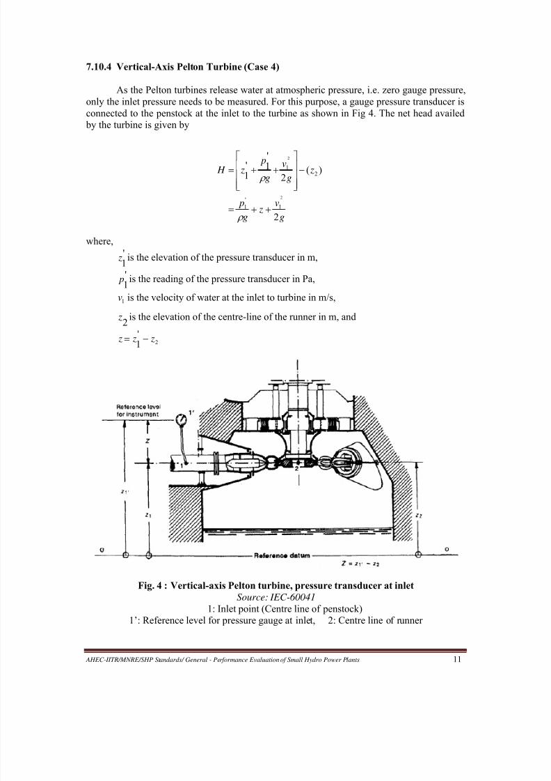
7.10.4 Vertical-Axis Pelton Turbine (Case 4)
As the Pelton turbines release water at atmospheric pressure, i.e. zero gauge pressure,
only the inlet pressure needs to be measured. For this purpose, a gauge pressure transducer is
connected to the penstock at the inlet to the turbine as shown in Fig 4. The net head availed
by the turbine is given by
where,
'1
z is the elevation of the pressure transducer in m,
'1
p is the reading of the pressure transducer in Pa,
1v is the velocity of water at the inlet to turbine in m/s,
2 z is the elevation of the centre-line of the runner in m, and
2
'1
z z z
Fig. 4 : Vertical-axis Pelton turbine, pressure transducer at inlet
Source: IEC-60041
1: Inlet point (Centre line of penstock)
1’: Reference level for pressure gauge at inlet, 2: Centre line of runner
g
v z
g
p
zg
v
g
p z H
2
)(2
'1'
1
2
2
1
'
1
21

8/20/2019 Performance Evaluation of Small Hydro Power Plants
http://slidepdf.com/reader/full/performance-evaluation-of-small-hydro-power-plants 20/69
AHEC-IITR/MNRE/SHP Standards/ General - Performance Evaluation of Small Hydro Power Plants 12
7.10.5 Horizontal-Axis Pelton Turbine (Case 5)
In this case too, only the inlet pressure needs to be measured by installing a gauge
pressure transducer at the inlet, as shown in Fig 5. The net head is given by
where,'
1 z is the elevation of the pressure transducer in m,'
1 p is the reading of the pressure transducer in Pa,
1v is the velocity of water at the inlet to turbine in m/s,
2 z is mean elevation of the points at which the water jets from nozzles strike the
buckets, and
2
'
1 z z z
Fig. 5 : Horizontal-axis Pelton turbine, pressure transducer at inlet
Source: IEC-60041
1: Inlet (Centre line of penstock)
1’: Reference level for pressure gauge at inlet2: Mean location of the points at which water jets strike the buckets
7.11 Measurement of Electrical Power Output
A reference digital wattmeter with an accuracy class of 0.2 or better is connected in
parallel with the panel wattmeter of the generator. The accuracy class of the generator CTs
and VTs should be at least 0.5, preferably 0.2. A test terminal block (TTB) or sliding-link
type terminals, if provided in the metering panel, would facilitate connecting the reference
g
v z
g
p
zg
v
g
p z H
2
)(2
2
2
1
'
1
21
'
1'
1

8/20/2019 Performance Evaluation of Small Hydro Power Plants
http://slidepdf.com/reader/full/performance-evaluation-of-small-hydro-power-plants 21/69
AHEC-IITR/MNRE/SHP Standards/ General - Performance Evaluation of Small Hydro Power Plants 13
wattmeter without shutting down the machine. The electrical power output of the generator is
calculated by multiplying the reference wattmeter reading with CT ratio and VT ratio. It is
recommended that the wattmeter be used in integrating mode so that the average electrical
power output of the machine over the duration of the efficiency test at a given load could be
obtained directly by dividing the integrated-energy reading with the time-duration reading.
7.12 Calculation of Unit Efficiency (Discharge Head Method)
7.12.1 Calculation Procedure
The electrical power output, Pe, of the generator in watts is given by
VTRTR ChoursintimenIntegratio
WhinenergyIntegratedPe (1)
The efficiency of the turbine-generator unit is given by
)h
(PturbinetoinputpowerHydraulic)e(Pgenertorof outputpowerElectrical η (2)
Hydraulic power input to the turbine in watts is given by
Ph= g HQ (3)
where
= actual density of water in the turbine in kg/m3
g = actual acceleration due to gravity of earth at the site in m/s2
H = net head in mQ = discharge rate in m
3/s
The value of H is determined using one of the equations given in Sections 7.10.1 to
7.10.5 depending on the given situation (Cases 1 to 5).
The above equations are used for calculating the unit efficiency at different loads
from the instrument readings taken during the efficiency test.
7.12.2 Case Study of SHP Station with Kaplan Turbine
(a) Power Station Data
Station Capacity: 5x4.8 MW
Turbine Type: Horizontal-shaft, fully-controlled Kaplan
Turbine Ratings: 7.50 m, 79.2 m3/s, 158 rpm
Generator Type: Horizontal-shaft, synchronous
Generator Ratings: 4.8 MW, 0.85 pf, 5.65 MVA, 11 kV, 50 Hz, 750 rpm
Speed Increaser: 158 rpm/ 750 rpm gear box
8/20/2019 Performance Evaluation of Small Hydro Power Plants
http://slidepdf.com/reader/full/performance-evaluation-of-small-hydro-power-plants 22/69
AHEC-IITR/MNRE/SHP Standards/ General - Performance Evaluation of Small Hydro Power Plants 14
(b) Unit Efficiency Test Data
Generating Unit Tested: Unit-4
Test Points: 60%, 80%, 100% and 105% of rated load
Method of Headrace Water Level Measurement: Two ultrasonic level sensors
Method of Tailrace Water Level Measurement: Two ultrasonic level sensors
Method of Discharge Measurement: Propeller current meters at stop-log opening at the intakeMethod of Electrical Power Measurement: Digital wattmeter in integration mode
(c) Averages of the Readings Taken are shown in table 1 below:
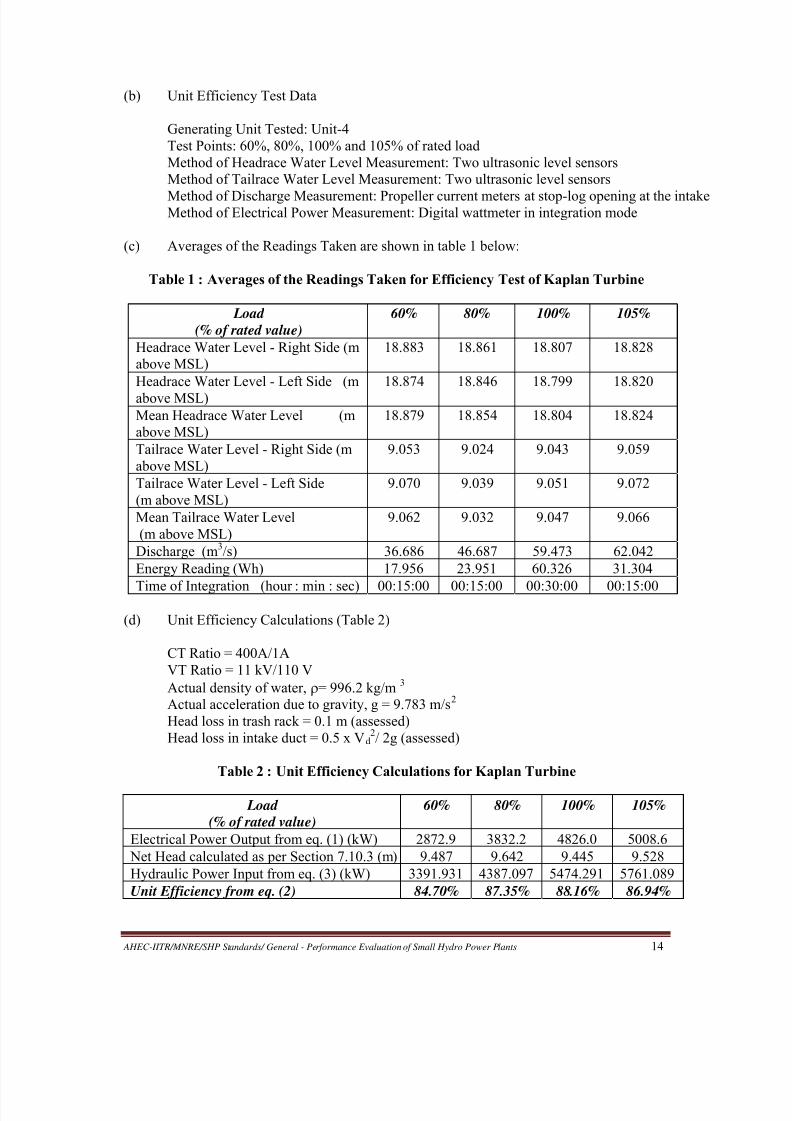
Table 1 : Averages of the Readings Taken for Efficiency Test of Kaplan Turbine
Load
(% of rated value)
60% 80% 100% 105%
Headrace Water Level - Right Side (m
above MSL)
18.883 18.861 18.807 18.828
Headrace Water Level - Left Side (m
above MSL)
18.874 18.846 18.799 18.820
Mean Headrace Water Level (m
above MSL)
18.879 18.854 18.804 18.824
Tailrace Water Level - Right Side (m
above MSL)
9.053 9.024 9.043 9.059
Tailrace Water Level - Left Side
(m above MSL)
9.070 9.039 9.051 9.072
Mean Tailrace Water Level
(m above MSL)
9.062 9.032 9.047 9.066
Discharge (m3/s) 36.686 46.687 59.473 62.042
Energy Reading (Wh) 17.956 23.951 60.326 31.304
Time of Integration (hour : min : sec) 00:15:00 00:15:00 00:30:00 00:15:00
(d) Unit Efficiency Calculations (Table 2)
CT Ratio = 400A/1A
VT Ratio = 11 kV/110 V
Actual density of water, = 996.2 kg/m3
Actual acceleration due to gravity, g = 9.783 m/s2
Head loss in trash rack = 0.1 m (assessed)
Head loss in intake duct = 0.5 x Vd2/ 2g (assessed)
Table 2 : Unit Efficiency Calculations for Kaplan Turbine
Load
(% of rated value)
60% 80% 100% 105%
Electrical Power Output from eq. (1) (kW) 2872.9 3832.2 4826.0 5008.6
Net Head calculated as per Section 7.10.3 (m) 9.487 9.642 9.445 9.528
Hydraulic Power Input from eq. (3) (kW) 3391.931 4387.097 5474.291 5761.089
Unit Efficiency from eq. (2) 84.70% 87.35% 88.16% 86.94%
8/20/2019 Performance Evaluation of Small Hydro Power Plants
http://slidepdf.com/reader/full/performance-evaluation-of-small-hydro-power-plants 23/69
AHEC-IITR/MNRE/SHP Standards/ General - Performance Evaluation of Small Hydro Power Plants 15
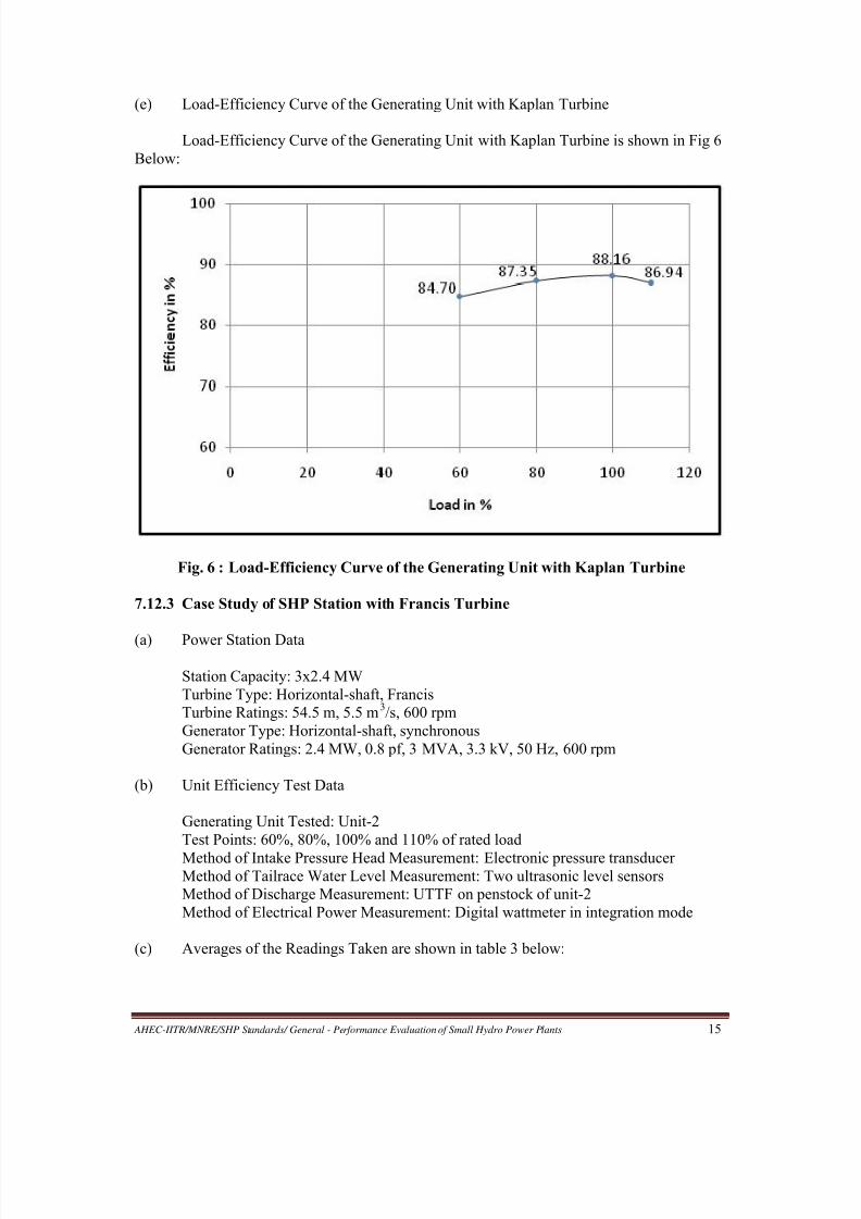
(e) Load-Efficiency Curve of the Generating Unit with Kaplan Turbine
Load-Efficiency Curve of the Generating Unit with Kaplan Turbine is shown in Fig 6
Below:
Fig. 6 : Load-Efficiency Curve of the Generating Unit with Kaplan Turbine
7.12.3 Case Study of SHP Station with Francis Turbine
(a) Power Station Data
Station Capacity: 3x2.4 MW
Turbine Type: Horizontal-shaft, Francis
Turbine Ratings: 54.5 m, 5.5 m3/s, 600 rpm
Generator Type: Horizontal-shaft, synchronous
Generator Ratings: 2.4 MW, 0.8 pf, 3 MVA, 3.3 kV, 50 Hz, 600 rpm
(b) Unit Efficiency Test Data
Generating Unit Tested: Unit-2
Test Points: 60%, 80%, 100% and 110% of rated load
Method of Intake Pressure Head Measurement: Electronic pressure transducerMethod of Tailrace Water Level Measurement: Two ultrasonic level sensors
Method of Discharge Measurement: UTTF on penstock of unit-2
Method of Electrical Power Measurement: Digital wattmeter in integration mode
(c) Averages of the Readings Taken are shown in table 3 below:

8/20/2019 Performance Evaluation of Small Hydro Power Plants
http://slidepdf.com/reader/full/performance-evaluation-of-small-hydro-power-plants 24/69
AHEC-IITR/MNRE/SHP Standards/ General - Performance Evaluation of Small Hydro Power Plants 16
Table 3 : Averages of the Readings Taken for Francis Turbine
Load
(% of rated value)
60% 80% 100% 110%
Intake Pressure (kg/cm2) 6.023 5.946 5.987 5.998
Tailrace Water Level -
Right Side(m above MSL)
1047.725 1047.781 1047.868 1047.935
Tailrace Water Level - Left
Side
(m above MSL)
1047.740 1047.847 1047.872 1047.940
Mean Tailrace Water Level
(m above MSL)
1047.732 1047.814 1047.870 1047.937
Discharge
(m3/s)
3.5513 4.1707 5.2028 5.6281
Energy Reading (Wh) 17.515 22.387 59.131 31.697
Time of Integration
(hour : min : sec)
00:15:00 00:15:00 00:30:00 00:15:00
(d) Unit Efficiency Calculations (Table 4)
CT Ratio = 700A/1A
VT Ratio = 3.3 kV/110 V
Actual density of water, = 999.8 kg/m3
Actual acceleration due to gravity, g = 9.790 m/s2
Table 4 : Unit Efficiency Calculations for Francis Turbine
Load
(% of rated value)
60% 80% 100% 110%
Electrical Power Output from eq.(1) (kW) 1471.260 1880.508 2483.502 2662.548
Net Head calculated as per
Sections 7.10.2 & 7.10.3 (m)
57.621 56.829 57.305 57.406
Hydraulic Power Input from eq.
(3) (kW)
2002.919 2319.937 2918.274 3162.392
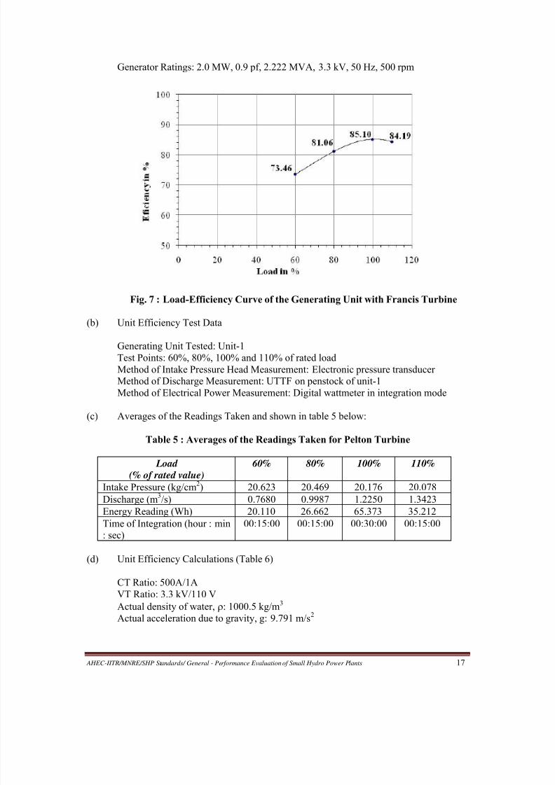
Unit Efficiency from eq. (2) 73.46% 81.06% 85.10% 84.19%
(b) Load-Efficiency Curve of the Generating Unit with Francis Turbine
Load-Efficiency Curve of the Generating Unit with Francis Turbine is shown in Fig 7
below:
7.12.4 Case Study of SHP Station with Pelton Turbine
(a) Power Station Data
Station Capacity: 2x2.0 MW
Turbine Type: Horizontal-shaft, two-jet Pelton
Turbine Ratings: 198 m, 1.198 m3/s, 500 rpm
Generator Type: Horizontal-shaft, synchronous
8/20/2019 Performance Evaluation of Small Hydro Power Plants
http://slidepdf.com/reader/full/performance-evaluation-of-small-hydro-power-plants 25/69
AHEC-IITR/MNRE/SHP Standards/ General - Performance Evaluation of Small Hydro Power Plants 17
Generator Ratings: 2.0 MW, 0.9 pf, 2.222 MVA, 3.3 kV, 50 Hz, 500 rpm
Fig. 7 : Load-Efficiency Curve of the Generating Unit with Francis Turbine
(b) Unit Efficiency Test Data
Generating Unit Tested: Unit-1
Test Points: 60%, 80%, 100% and 110% of rated load
Method of Intake Pressure Head Measurement: Electronic pressure transducer
Method of Discharge Measurement: UTTF on penstock of unit-1
Method of Electrical Power Measurement: Digital wattmeter in integration mode
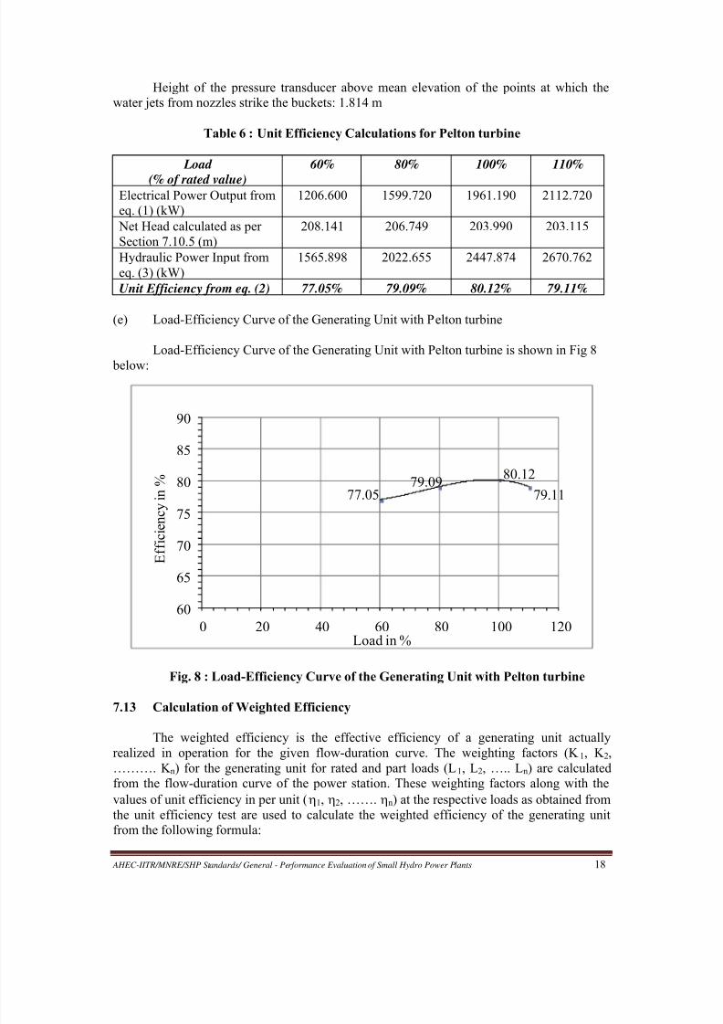
(c) Averages of the Readings Taken and shown in table 5 below:
Table 5 : Averages of the Readings Taken for Pelton Turbine
Load
(% of rated value)
60% 80% 100% 110%
Intake Pressure (kg/cm2) 20.623 20.469 20.176 20.078
Discharge (m3/s) 0.7680 0.9987 1.2250 1.3423
Energy Reading (Wh) 20.110 26.662 65.373 35.212
Time of Integration (hour : min
: sec)
00:15:00 00:15:00 00:30:00 00:15:00
(d) Unit Efficiency Calculations (Table 6)
CT Ratio: 500A/1A
VT Ratio: 3.3 kV/110 V
Actual density of water, : 1000.5 kg/m3
Actual acceleration due to gravity, g: 9.791 m/s2
8/20/2019 Performance Evaluation of Small Hydro Power Plants
http://slidepdf.com/reader/full/performance-evaluation-of-small-hydro-power-plants 26/69
8/20/2019 Performance Evaluation of Small Hydro Power Plants
http://slidepdf.com/reader/full/performance-evaluation-of-small-hydro-power-plants 27/69
AHEC-IITR/MNRE/SHP Standards/ General - Performance Evaluation of Small Hydro Power Plants 19
Weighted efficiency of the generating unit in percent
100.......21/.........221 nK K K nnK K K
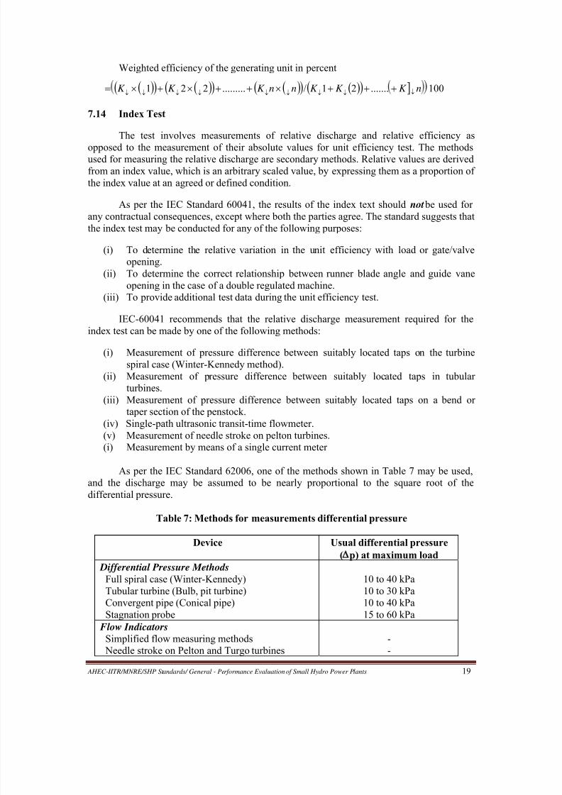
7.14 Index Test
The test involves measurements of relative discharge and relative efficiency asopposed to the measurement of their absolute values for unit efficiency test. The methods
used for measuring the relative discharge are secondary methods. Relative values are derived
from an index value, which is an arbitrary scaled value, by expressing them as a proportion of
the index value at an agreed or defined condition.
As per the IEC Standard 60041, the results of the index text should not be used for
any contractual consequences, except where both the parties agree. The standard suggests that
the index test may be conducted for any of the following purposes:
(i) To determine the relative variation in the unit efficiency with load or gate/valve
opening.
(ii) To determine the correct relationship between runner blade angle and guide vaneopening in the case of a double regulated machine.
(iii) To provide additional test data during the unit efficiency test.
IEC-60041 recommends that the relative discharge measurement required for the
index test can be made by one of the following methods:
(i) Measurement of pressure difference between suitably located taps on the turbine
spiral case (Winter-Kennedy method).
(ii) Measurement of pressure difference between suitably located taps in tubular
turbines.
(iii) Measurement of pressure difference between suitably located taps on a bend or
taper section of the penstock.
(iv) Single-path ultrasonic transit-time flowmeter.
(v) Measurement of needle stroke on pelton turbines.
(i) Measurement by means of a single current meter
As per the IEC Standard 62006, one of the methods shown in Table 7 may be used,
and the discharge may be assumed to be nearly proportional to the square root of the
differential pressure.
Table 7: Methods for measurements differential pressure
Device Usual differential pressure
( p) at maximum load Differential Pressure Methods
Full spiral case (Winter-Kennedy)
Tubular turbine (Bulb, pit turbine)
Convergent pipe (Conical pipe)
Stagnation probe
10 to 40 kPa
10 to 30 kPa
10 to 40 kPa
15 to 60 kPa
Flow Indicators
Simplified flow measuring methods
Needle stroke on Pelton and Turgo turbines
-
-

8/20/2019 Performance Evaluation of Small Hydro Power Plants
http://slidepdf.com/reader/full/performance-evaluation-of-small-hydro-power-plants 28/69
AHEC-IITR/MNRE/SHP Standards/ General - Performance Evaluation of Small Hydro Power Plants 20
8.0 METHODOLOGY OF PERFORMANCE EVALUATION
The performance evaluation of a SHP station is carried out in five steps as follows:
Step I: Station and Generation Data Compilation
All important data and drawings of the SHP station, needed for the inspection,
functional/operational checks and testing of the power station, are obtained from the power
station owner. A format for obtaining power station data from the station owner is
recommended in Annexure I. Information showing conformity of the major plant equipment
and components to the Indian/International standards, is an important part of the station data.
The owner can collect this data from the design consultant, contractor and equipment
manufacturer concerned as well as his own records.
In addition, the daily generation data for the period starting with the date of
commissioning and the month-wise projected generation as per DPR are also obtained from
the owner in the format recommended in Annexure II.
Step II: Planning
Based on the data and drawings obtained, the test agency may then plan inspection,
checks and tests that need to be carried out, and prepare a complete schedule for the same.
Constraints like non-availability of provisions for certain difficult tests, like index test and
unit efficiency test, and inadequacy of water etc. can adversely affect the accuracy and timing
of tests. Where necessary, the site may be visited in advance for ascertaining the best possible
methods of measurements and recommending to the station owner any provisions that should
be made to facilitate these measurements.
Step III: Instrument Checking / Recalibration
The test instruments may be checked /recalibrated before taking them to the site or at
the site, as necessary, to ensure they are fit for conducting the tests at site.
Step IV: Inspection, Checks and Measurements/Tests at Site
Inspection, functional checks and measurements/tests (as detailed in earlier sections)
are then conducted at the site as per the schedule. As far as possible, the vital parameter like
discharge should be measured by two independent methods so that the exercise does not go in
vain in case one method fails to give dependable results.
Step V: Test Report Preparation
Finally, a test report is prepared. For each major test or measurement, the report
should mention the method and instrument used along with the test results. For criticalmeasurements, an assessment of the uncertainties of measurement should be made. Remarks
and conclusions on the test results along with recommendations may be given for the benefit
of the end users of the report.
9.0 PROVISIONS TO FACILITATE PERFORMANCE TESTING
The IEC: 60041 and other standards, relevant to the testing of hydropower plant
equipment, emphasize on the accuracy of field test, specially the measurements meant for
8/20/2019 Performance Evaluation of Small Hydro Power Plants
http://slidepdf.com/reader/full/performance-evaluation-of-small-hydro-power-plants 29/69
AHEC-IITR/MNRE/SHP Standards/ General - Performance Evaluation of Small Hydro Power Plants 21
evaluating the efficiency of generating units. These standards lay down certain requirements
in terms of some provisions necessary in the plant equipment, electrical and mechanical
works and civil works. It is necessary for the SHP developers, equipment manufacturers,
designers and contractors to make appropriate provisions for conducting the performance test
to achieve the following:
(a) To ensure conformity of the tests to the standards.(b) To achieve high accuracies and minimize uncertainties of measurements.
(c) To reduce effort, time and cost of testing.
(d) To reduce the number and duration of shutdowns needed during testing.
Longer shut-downs of the power station result in loss of generation, which can be
largely avoided if appropriate provisions for conducting performance tests are available. Lack
of certain provisions can increase uncertainties of measurements considerably and, in some
extreme cases, even make some tests impossible. On the other hand, well planned provisions
in the plant equipment and power station not only facilitate the testing but also make the job
of operation & maintenance engineers of the power station simpler and systematic.
This Section elaborates on such provisions and gives guidelines on how to providethem in the power station /plant equipment in conformity with the relevant
International/Indian standards. For any clarification or further details, one can refer to the
relevant standard.
9.1 General Guidelines
(a) Permanent benchmarks for reference should be provided at the power house building,
tailrace channel and intake.
(b) Centre-line for reference should be marked on penstock near the turbine intake,
butterfly valve, casing of horizontal-shaft turbine and other similar components.
(c) Good drawings, preferably soft copies, should be preserved for reference and be made
available during performance testing.
(d) Records of commissioning test results should be preserved for reference and be made
available during performance testing.
(e) Records of any problems experienced during operation and maintenance should be
preserved and made available at site to the performance test team.
(f) All requirements of and necessary provisions on various equipments mentioned in
Sections 9.2 to 9.9 below should be included, as and where applicable, in the tender
technical specifications document at the time of procurement of these equipments.
(g) All requirements of and necessary provisions in the civil & hydraulic structures
mentioned in Sections 9.2 to 9.8 below should be included, as and where applicable,
in the tender technical specifications document at the time of awarding construction
contracts.
9.2 Provisions for Pressure Measurement
Reference: IEC-60041 (1991), Clause 11.4
9.2.1 Choice of Pressure Measuring Section
(a) The location of the measuring section should be such that there is a minimum of
disturbance to the flow at that location.

8/20/2019 Performance Evaluation of Small Hydro Power Plants
http://slidepdf.com/reader/full/performance-evaluation-of-small-hydro-power-plants 30/69
AHEC-IITR/MNRE/SHP Standards/ General - Performance Evaluation of Small Hydro Power Plants 22
(b) Sections where the velocity pattern is distorted by the presence of an elbow or valve
or other flow disturbances outside of the hydraulic machine should be avoided.
(c) The plane of the measuring section shall be normal to the average direction of flow.
(d) Area of the measuring section, which is required for computing the mean water
velocity, should be readily measurable.
(e) The measuring section should preferably be arranged in a straight conduit section
(which may also be slightly convergent or divergent) extending at least threediameters upstream and two diameters downstream from the measuring section.
(f) The measuring section should be free from any water extraction or injection active
during the test.
(g) Closed branches of the conduit, if any, shall be more than five times their diameter
away from the measuring section.
9.2.2 Number and Locations of Pressure Taps
(a) Generally, for any form of section, at least two pairs of opposite pressure taps (i.e.
total of four taps) shall be used.
(b) With favourable conditions, the number of taps can be reduced by mutual agreement.(c) In the case of circular sections the four pressure taps shall be arranged on two
diameters at right angles to each other.
(d) The taps shall not be located at or near the highest point of the measuring section in
order to avoid air pockets.
(e) The taps shall also not be located near the lowest point because of the risk of dirt
obstructing the taps.
(f) If taps have to be arranged at the top or bottom of a section, special care has to be
observed to avoid disturbances due to air or dirt.
(g) In the case of non-circular (in most cases rectangular) sections, the taps shall not be
located near the corners.
(h) Individual mean pressure measurements around the measuring section should not
differ from one another by more than 0.5% of the specific hydraulic energy of themachine or 20% of the specific kinetic energy calculated from the mean velocity in
the measuring section. If this requirement is not fulfilled and if it is not possible to
correct the faulty tap, a mutual agreement should be reached to eliminate the faulty
tap or to select another location or to accept this deviation.
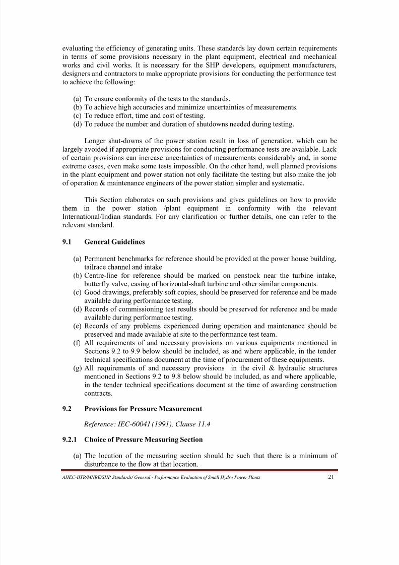
9.2.3 The Pressure Taps
(a) Pressure taps should be located in inserts of non-corroding material; Fig 9 shows two
typical inserts at (a) and (b).
(b) Inserts should be installed flush with the inner wall of conduit.
(c) The cylindrical bore of the pressure tap shall be 3 mm to 6 mm in diameter and have aminimum length of at least twice the diameter.
(d) The bore should be perpendicular to the conduit wall and free of all burrs or
irregularities which could cause local disturbance.
(e) The edges of the openings should preferably be provided with a radius r =d/4
smoothly joining the flow passage (‘d’ being the diameter of the bore of the pressure
tap, as shown in Fig 9). The purpose of this rounding is to eliminate any possible
burrs.
8/20/2019 Performance Evaluation of Small Hydro Power Plants
http://slidepdf.com/reader/full/performance-evaluation-of-small-hydro-power-plants 31/69
AHEC-IITR/MNRE/SHP Standards/ General - Performance Evaluation of Small Hydro Power Plants 23
(f) The surface of the conduit shall be smooth and parallel with the flow in the vicinity of
the bore for at least 300 mm upstream and 100 mm downstream.
(g) In concrete passageways, the pressure taps shall be at the centre of a stainless steel or
bronze plate at least 300 mm in diameter flush with the surrounding concrete.
Fig. 9: Example of pressure taps
Source: IEC-60041 (1991)
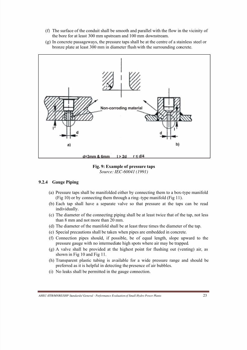
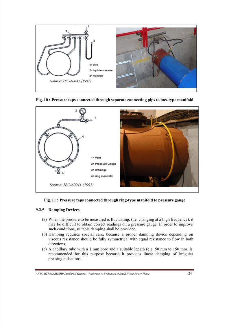
9.2.4 Gauge Piping
(a) Pressure taps shall be manifolded either by connecting them to a box-type manifold
(Fig 10) or by connecting them through a ring–type manifold (Fig 11).
(b) Each tap shall have a separate valve so that pressure at the taps can be read
individually.
(c) The diameter of the connecting piping shall be at least twice that of the tap, not less
than 8 mm and not more than 20 mm.
(d) The diameter of the manifold shall be at least three times the diameter of the tap.
(e) Special precautions shall be taken when pipes are embedded in concrete.
(f) Connection pipes should, if possible, be of equal length, slope upward to the
pressure gauge with no intermediate high spots where air may be trapped.(g) A valve shall be provided at the highest point for flushing out (venting) air, as
shown in Fig 10 and Fig 11.
(h) Transparent plastic tubing is available for a wide pressure range and should be
preferred as it is helpful in detecting the presence of air bubbles.
(i) No leaks shall be permitted in the gauge connection.
8/20/2019 Performance Evaluation of Small Hydro Power Plants
http://slidepdf.com/reader/full/performance-evaluation-of-small-hydro-power-plants 32/69
AHEC-IITR/MNRE/SHP Standards/ General - Performance Evaluation of Small Hydro Power Plants 24
Fig. 10 : Pressure taps connected through separate connecting pips to box-type manifold
Fig. 11 : Pressure taps connected through ring-type manifold to pressure gauge
9.2.5 Damping Devices
(a) When the pressure to be measured is fluctuating, (i.e. changing at a high frequency), it
may be difficult to obtain correct readings on a pressure gauge. In order to improve
such conditions, suitable damping shall be provided.
(b) Damping requires special care, because a proper damping device depending on
viscous resistance should be fully symmetrical with equal resistance to flow in both
directions.
(c) A capillary tube with a 1 mm bore and a suitable length (e.g. 50 mm to 150 mm) is
recommended for this purpose because it provides linear damping of irregular
pressing pulsations.

8/20/2019 Performance Evaluation of Small Hydro Power Plants
http://slidepdf.com/reader/full/performance-evaluation-of-small-hydro-power-plants 33/69
AHEC-IITR/MNRE/SHP Standards/ General - Performance Evaluation of Small Hydro Power Plants 25
(d) Additional damping may be obtained from an air or surge chamber connected to the
pressure line ahead of the gauge.
(e) Using an orifice plate is not recommended because it may introduce an error due to
nonlinear damping.
(f) A valved bypass around any damping device should be provided and kept open except
for the short time during which readings are taken.
(g) Bending or pinching the connecting pipes or inserting any non-symmetrical throttlingdevice is not permitted.
9.3 Provisions for Free Water Level Measurement
Reference: IEC-60041 (1991), Clause 11.5
9.3.1 Choice of Water Level Measuring Sections
(a) The flow in the measuring section shall be steady and free of disturbances.
(b) Sections where the flow velocity is influenced by an elbow or by other irregularities
should be avoided.
(c) The area at the measuring sections is used to determine the mean water velocity andhence it shall be accurately defined and readily measurable.
9.3.2 Number of Measuring Points in a Measuring Section
(a) Measurement of free water levels shall be obtained for at least two points in every
measuring section or in each passage of a multiple passage measuring section.
(b) The average of the readings is to be taken as the free water level.
9.3.3 Measuring Wells and Stilling Boxes
(a) If the free surface is not accessible or not sufficiently calm, measuring wells with an
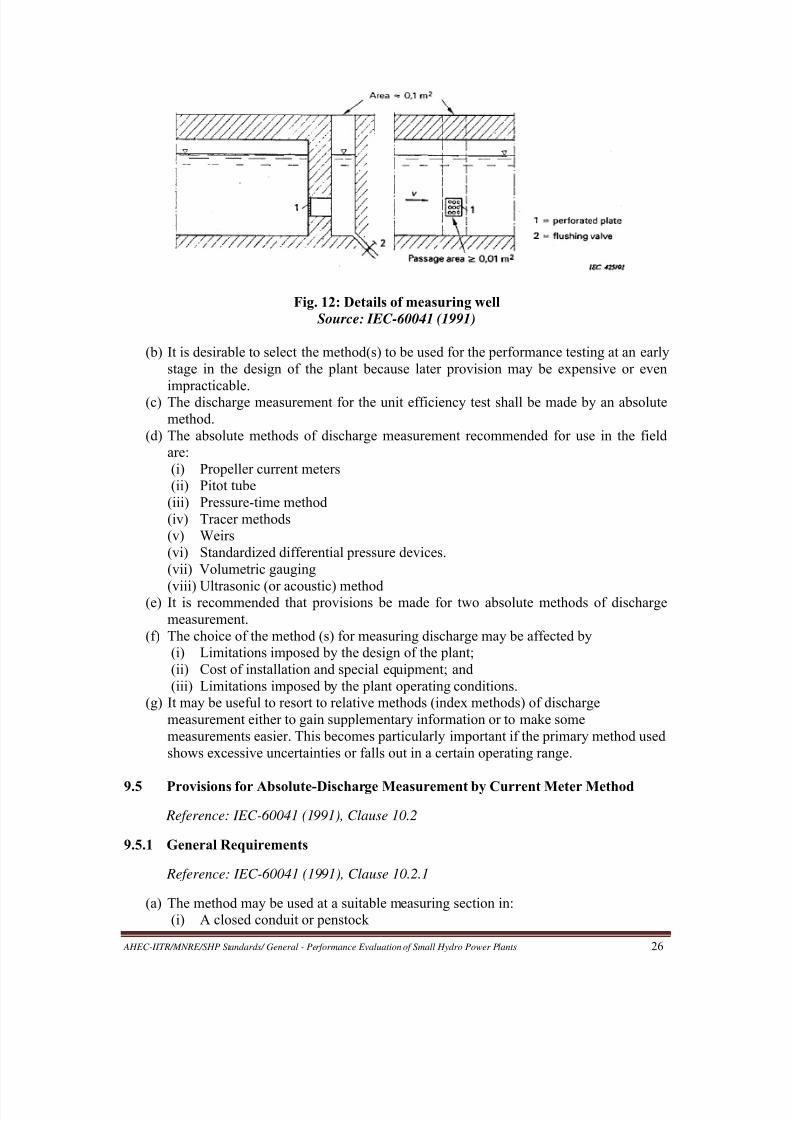
area of about 0.1 m2 which permit accurate and convenient measurements shall be provided (Fig 12).
(b) All connections shall be normal to the wall of the measuring section and should
preferably be covered with smooth perforated plates (perforations of 5 mm to 10 mm
diameter).
(c) Such cover plates should be flush with the wall of the measuring section to criminate
any local disturbances.
(d) The connection between the measuring section and well should have a passage area of
at least 0.01 m2
.
(e) The total area of perforation should be in the under of 25% of the passage area.
(f) It is recommended that at least two measuring wells be provided at each measuring
section on opposite sides of the canal/channel.
9.4 Provisions for Absolute-Discharge Measurement in General
Reference: IEC-60041 (1991), Clauses 10.1, 10.1.1 and 15.1.3.
(a) The measurement of discharge in a hydroelectric or pumped storage plant can be
performed with the desired accuracy only when the specific requirements of the
chosen method are satisfied.
8/20/2019 Performance Evaluation of Small Hydro Power Plants
http://slidepdf.com/reader/full/performance-evaluation-of-small-hydro-power-plants 34/69
AHEC-IITR/MNRE/SHP Standards/ General - Performance Evaluation of Small Hydro Power Plants 26
Fig. 12: Details of measuring well
Source: IEC-60041 (1991)
(b) It is desirable to select the method(s) to be used for the performance testing at an early
stage in the design of the plant because later provision may be expensive or even
impracticable.(c) The discharge measurement for the unit efficiency test shall be made by an absolute
method.
(d) The absolute methods of discharge measurement recommended for use in the field
are:
(i) Propeller current meters
(ii) Pitot tube
(iii) Pressure-time method
(iv) Tracer methods
(v) Weirs
(vi) Standardized differential pressure devices.
(vii) Volumetric gauging
(viii) Ultrasonic (or acoustic) method(e) It is recommended that provisions be made for two absolute methods of discharge
measurement.
(f) The choice of the method (s) for measuring discharge may be affected by
(i) Limitations imposed by the design of the plant;
(ii) Cost of installation and special equipment; and
(iii) Limitations imposed by the plant operating conditions.
(g) It may be useful to resort to relative methods (index methods) of discharge
measurement either to gain supplementary information or to make some
measurements easier. This becomes particularly important if the primary method used
shows excessive uncertainties or falls out in a certain operating range.
9.5 Provisions for Absolute-Discharge Measurement by Current Meter Method
Reference: IEC-60041 (1991), Clause 10.2
9.5.1 General Requirements
Reference: IEC-60041 (1991), Clause 10.2.1
(a) The method may be used at a suitable measuring section in:
(i) A closed conduit or penstock
8/20/2019 Performance Evaluation of Small Hydro Power Plants
http://slidepdf.com/reader/full/performance-evaluation-of-small-hydro-power-plants 35/69
AHEC-IITR/MNRE/SHP Standards/ General - Performance Evaluation of Small Hydro Power Plants 27
(ii) An intake structure
(iii) An upstream open channel (headrace)
(iv) A downstream open channel (tailrace)
(b) A number of propeller current-meters (PCMs) should be located at specified points in
a suitable cross-section of an open channel or closed conduit.
(c) Simultaneous measurements of local mean velocity with the meters should be
integrated over the measuring section to obtain the discharge.(d) The water should be sufficiently clean, such that dissolved or suspended matter will
not affect the accuracy of the meter readings during the test.
(e) Integration techniques are used to compute the discharge assuming velocity
distributions that closely approximate the known laws. Therefore, it is essential to
select a measuring section that satisfies the following conditions:
(i) If open channel, it should be an artificial channel with uniform and well defined
cross section and shall be straight for both upstream and downstream sides of the
measuring section. Natural streams are excluded for tests under IEC Standard
60041.
(ii) If closed conduit, it should be nearly horizontal with smooth inner surface,
uniform cross section and free from bends and discontinuities both upstream and
downstream sides of the measuring section.
9.5.2 Number of Measuring Points
Reference: IEC-60041 (1991), Clause 10.2.2.2
(a) The number of current-meters should be sufficient to ensure a satisfactory
determination of the velocity profile over the whole measuring section. A single-point
measurement is not permitted under the IEC Standard 60041.
(b) If the conduit or channel is divided into several sections, measurements should be
made simultaneously in all sections.
(c) In a circular penstock, at least 13 measuring points should be used one of which
should be the centre point of the section. The number of measuring points per radius,Z, excluding the centre point, may be determined from
where ‘R’ is the internal radius of the conduit in meters. For any given number of
current-meters, it is preferable to increase the number of radii than to increase the
number of current-meters per radius, but care should be taken to avoid excessive
blocking. Centre blocking can be reduced by cantilevering the radial supporting arms
from the conduit wall. If this is done, only a single arm need extend to the centre of
the conduit. Measurements on more than 8 radii or at more than 8 points per radius,
excluding the centre point, are not recommended.
(d) In a rectangular or trapezoidal section, at least 25 measuring points should be used. If
the velocity distribution is likely to be non-uniform, the number of measuring points,
Z, should be determined from
where ‘A’ is the area of the measuring section in square metres.
9.5.3 Type and Size of Current Meters
Reference: IEC-60041 (1991), Clause 10.2.2.3
(a) Only propeller-type current meters should be used.

8/20/2019 Performance Evaluation of Small Hydro Power Plants
http://slidepdf.com/reader/full/performance-evaluation-of-small-hydro-power-plants 36/69
AHEC-IITR/MNRE/SHP Standards/ General - Performance Evaluation of Small Hydro Power Plants 28
(b) The current meters should fulfill the applicable requirements of ISO - 2537.
(c) The propeller current meters shall be capable of withstanding the water pressure
and the time of submergence without charge in the calibration.
(d) Current-meter propellers should be of diameter not less than 100 mm except for
measurement in the peripheral zone where propellers of diameter as small as 50
mm may be used.
(e) The distance from the trailing edge of the propeller to the leading edge of themounting rod shall be at least 150 mm.
(f) The angle between the local velocity vector and the axis of the current-meter shall
not exceed 50
. When larger angles are unavoidable, self-compensating propellers
which measure directly the axial component of the velocity, shall be used.
9.5.4 Provisions for Measurement in Short Penstocks and Intake Structures
Reference: IEC-60041 (1991), Clause 10.2.4
(a) A penstock is defined as short if the straight length is less than 25 diameters.
(b) The main difficulty in measuring discharge in short penstocks and intake
structures arises from the fact that the measuring section may be located in a shortconverging conduit with uneven and/or unstable velocity distributions as well as
oblique flow with respect to the current-meters.
(c) To remedy these difficulties in relation to the intake structure, a temporary bell-
mouth nozzle (see Fig 13) may be installed at the entrance to the intake structure
achieving a straight and parallel flow. The flow through the modified intake may
change the performance of the machine, but this change is negligible.
Fig. 13 : Temporary nozzle or bell-mouth placed in the intake of a low head turbineSource: IEC-60041 (1991)
9.5.5 Provisions for Measurement in Open Channels
Reference: IEC-60041 (1991), Clause 10.2.5
(a) The measuring section should have both width and depth greater than 0.80 m and at
least eight times the diameter of the propeller.

8/20/2019 Performance Evaluation of Small Hydro Power Plants
http://slidepdf.com/reader/full/performance-evaluation-of-small-hydro-power-plants 37/69
AHEC-IITR/MNRE/SHP Standards/ General - Performance Evaluation of Small Hydro Power Plants 29
(b) The measuring section should be at least ten times its hydraulic radius (which is
defined as the ratio of the wetted cross-sectional area to the wetted perimeter).
(c) If necessary, the flow pattern at the measuring section may be improved by the
installation of racks, rafts or submerged floor shown in Fig 14 Some of these devices
are effective in suppressing surface waves also, which increases the accuracy of the
depth-measurement.
Fig. 14 : Means for stabilizing flow in an open channel
Source: IEC-60041 (1991)
(d) There shall be a minimum of 25 measuring points located at the intersection of 5
horizontal and 5 vertical lines.
(e) Measuring points should be closer to one another in the zones of steeper velocity
gradient, i.e. near the walls, bottom and water surface.
(f) Points should normally be spaced so that the difference in velocities between two
adjacent points does not exceed 20% of the greater of the two velocities.(g) The minimum current-meter spacing should not be less than (d + 30) mm, where ‘d’ is
the outside diameter of the propeller in mm.
(h) The distance from the axis of the nearest current-meter to any wetted surface should
be within 0.75d minimum to 200 mm maximum.
(i) The axis of the topmost current-meter in each row should be at least one propeller
diameter below the free water surface.
(j) All current-meters should be rigidly attached to the mounting rods with the propeller
axes exactly perpendicular to the plane of the measuring section.
(k) The stiffness of the mounting structures should be adequate to prevent current meter
vibrations.
(l) The structure should also offer a minimum stable drag and minimum interference with
the current-meter operation.(m) The current-meters may be used as a stationary battery mounted on a number of
parallel rods over the whole measuring section. Such an arrangement may produce a
significant blockage effect in channels of small cross-section, and hence should not be
used in small section channels.
(n) As an alternative arrangement for mounting of current meters, a single vertical row of
current meters mounted on a travelling winch (see Fig 15) or one or two horizontal
rows of current meters mounted on a frame (see Fig 16 and Fig 17) may be moved to
successive stations in the measuring cross-section. Since this requires steady flow
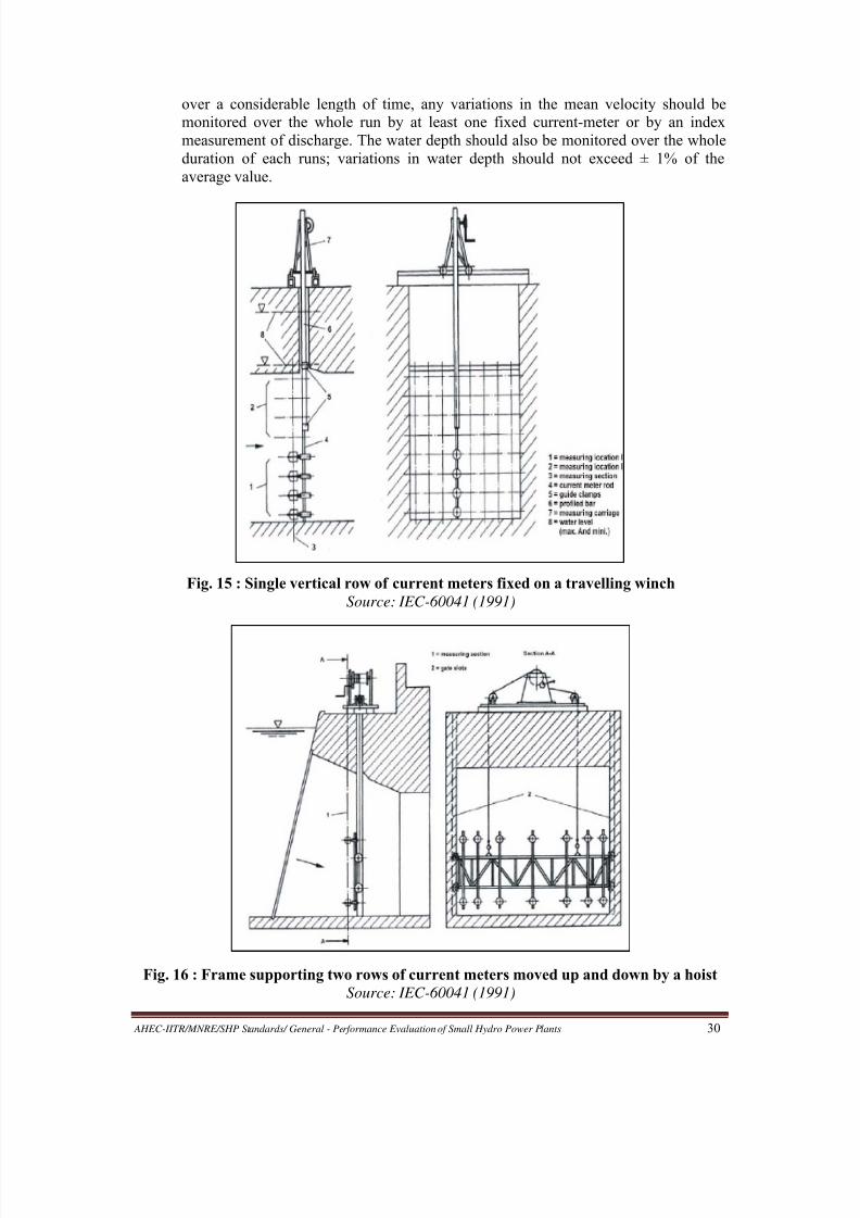
8/20/2019 Performance Evaluation of Small Hydro Power Plants
http://slidepdf.com/reader/full/performance-evaluation-of-small-hydro-power-plants 38/69
AHEC-IITR/MNRE/SHP Standards/ General - Performance Evaluation of Small Hydro Power Plants 30
over a considerable length of time, any variations in the mean velocity should be
monitored over the whole run by at least one fixed current-meter or by an index
measurement of discharge. The water depth should also be monitored over the whole
duration of each runs; variations in water depth should not exceed ± 1% of the
average value.
Fig. 15 : Single vertical row of current meters fixed on a travelling winch
Source: IEC-60041 (1991)
Fig. 16 : Frame supporting two rows of current meters moved up and down by a hoist
Source: IEC-60041 (1991)
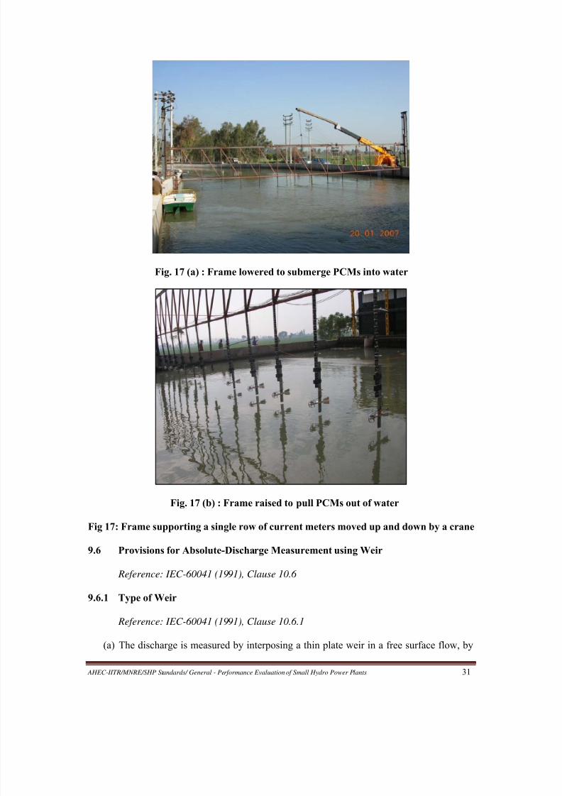
8/20/2019 Performance Evaluation of Small Hydro Power Plants
http://slidepdf.com/reader/full/performance-evaluation-of-small-hydro-power-plants 39/69

8/20/2019 Performance Evaluation of Small Hydro Power Plants
http://slidepdf.com/reader/full/performance-evaluation-of-small-hydro-power-plants 40/69
AHEC-IITR/MNRE/SHP Standards/ General - Performance Evaluation of Small Hydro Power Plants 32
observing the head over the weir and by employing a unique functional relationship
between the discharge and the head over the weir.
(b) In order to have the best known relationship, only rectangular weirs without side
contraction, sharp crested, with complete crest contraction, and free overflow should
be used.
9.6.2 Design and Fixing of Weir Plate
Reference: IEC-60041 (1991), Clause 10.6.2
(a) The plate constituting the weir should be smooth and plain, particularly on its
upstream face.
(b) This weir plate should preferably be made of a metal which can resist erosion and
corrosion.
(c) It should have sufficient thickness so that it is rigid.
(d) It should be water tight and perpendicular to the walls and to the bottom of the
channel.
(e) The surface of the weir crest should be a horizontal, flat and smooth and should be
perpendicular to the upstream face of the plate.(f) Intersection of the weir crest with the upstream face should be straight and form sharp
edges, free from burrs or scratches.
(g) Its edge width perpendicular to the upstream face should be within 1 mm to 2 mm.
(h) If the weir plate is thicker than the allowable crest width, the downstream edge should
be chamfered at a 450
angle (see Fig 18).
(i) Complete aeration of the nappe should be secured.
(j) The ventilation should be sufficient to keep the air underneath the nappe at
approximately atmospheric pressure. The cross-sectional area of the ventilation holes
should be at least 0.5% of the product of the length of the weir crest ‘b’ times the
height, s1, of the weir above the water level in the downstream channel.
Fig. 18 : Sketch of a rectangular sharp-crested weir
Source: IEC-60041 (1991)
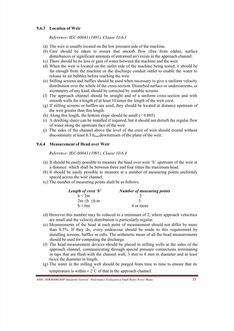
8/20/2019 Performance Evaluation of Small Hydro Power Plants
http://slidepdf.com/reader/full/performance-evaluation-of-small-hydro-power-plants 41/69
AHEC-IITR/MNRE/SHP Standards/ General - Performance Evaluation of Small Hydro Power Plants 33
9.6.3 Location of Weir
Reference: IEC-60041 (1991), Clause 10.6.3
(a) The weir is usually located on the low pressure side of the machine.
(b) Care should be taken to ensure that smooth flow (free from eddies, surface
disturbances or significant amounts of entrained air) exists in the approach channel.(c) There should be no loss or gain of water between the machine and the weir.
(d) When the weir is located on the outlet side of the machine being tested, it should be
far enough from the machine or the discharge conduit outlet to enable the water to
release its air bubbles before reaching the weir.
(e) Stilling screens and baffles should be used when necessary to give a uniform velocity
distribution over the whole of the cross-section. Disturbed surface or undercurrents, or
asymmetry of any kind, should be corrected by suitable screens.
(f) The approach channel should be straight and of a uniform cross-section and with
smooth walls for a length of at least 10 times the length of the weir crest.
(g) If stilling screens or baffles are used, they should be located at distance upstream of
the weir greater than this length.
(h) Along this length, the bottom slope should be small (< 0.005).(i) A desilting sluice can be installed if required, but it should not disturb the regular flow
of water along the upstream face of the weir.
(j) The sides of the channel above the level of the crest of weir should extend without
discontinuity at least 0.3 hmax downstream of the plane of the weir.
9.6.4 Measurement of Head over Weir
Reference: IEC-60041 (1991), Clause 10.6.4
(a) It should be easily possible to measure the head over weir ‘h’ upstream of the weir at
a distance which shall be between three and four times the maximum head.
(b) It should be easily possible to measure at a number of measuring points uniformlyspaced across the weir channel.
(c) The number of measuring points shall be as follows:
Length of crest ‘b’ Number of measuring points
b < 2m 2
2m ≤ b ≤ 6 m 3
b > 6m 4 or more
(d) However this number may be reduced to a minimum of 2, where approach velocities
are small and the velocity distribution is particularly regular.
(e) Measurements of the head at each point of measurement should not differ by more
than 0.5%. If they do, every endeavour should be made to this requirement by
installing screens, baffles or rafts. The arithmetic mean of all the head measurements
should be used for computing the discharge.
(f) The head measurement devices should be placed in stilling wells at the sides of the
approach channel, communicating through special pressure connections terminating
in taps that are flush with the channel wall, 3 mm to 6 mm in diameter and at least
twice the diameter in length.
(g) The water in the stilling well should be purged from time to time to ensure that its
temperature is within ± 20
C of that in the approach channel.
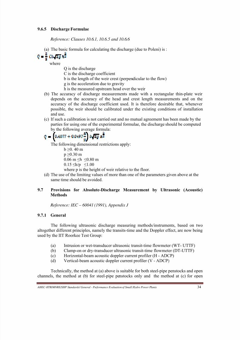
8/20/2019 Performance Evaluation of Small Hydro Power Plants
http://slidepdf.com/reader/full/performance-evaluation-of-small-hydro-power-plants 42/69
AHEC-IITR/MNRE/SHP Standards/ General - Performance Evaluation of Small Hydro Power Plants 34
9.6.5 Discharge Formulae
Reference: Clauses 10.6.1, 10.6.5 and 10.6.6
(a) The basic formula for calculating the discharge (due to Poleni) is :
where
Q is the discharge
C is the discharge coefficient
b is the length of the weir crest (perpendicular to the flow)
g is the acceleration due to gravity
h is the measured upstream head over the weir
(b) The accuracy of discharge measurements made with a rectangular thin-plate weir
depends on the accuracy of the head and crest length measurements and on the
accuracy of the discharge coefficient used. It is therefore desirable that, whenever
possible, the weir should be calibrated under the existing conditions of installation
and use.
(c) If such a calibration is not carried out and no mutual agreement has been made by the parties for using one of the experimental formulae, the discharge should be computed
by the following average formula:
The following dimensional restrictions apply:
b ≥ 0. 40 m
p ≥ 0.30 m
0.06 m ≤ h ≤ 0.80 m
0.15 ≤ h/p ≤ 1.00
where p is the height of weir relative to the floor.
(d) The use of the limiting values of more than one of the parameters given above at the
same time should be avoided.
9.7 Provisions for Absolute-Discharge Measurement by Ultrasonic (Acoustic)
Methods
Reference: IEC – 60041 (1991), Appendix J
9.7.1 General
The following ultrasonic discharge measuring methods/instruments, based on two
altogether different principles, namely the transits-time and the Doppler effect, are now being
used by the IIT Roorkee Test Group:
(a) Intrusion or wet-transducer ultrasonic transit-time flowmeter (WT- UTTF)
(b) Clamp-on or dry-transducer ultrasonic transit-time flowmeter (DT-UTTF)
(c) Horizontal-beam acoustic doppler current profiler (H - ADCP)
(d) Vertical-beam acoustic doppler current profiler (V - ADCP)
Technically, the method at (a) above is suitable for both steel-pipe penstocks and open
channels, the method at (b) for steel-pipe penstocks only and the method at (c) for open

8/20/2019 Performance Evaluation of Small Hydro Power Plants
http://slidepdf.com/reader/full/performance-evaluation-of-small-hydro-power-plants 43/69
AHEC-IITR/MNRE/SHP Standards/ General - Performance Evaluation of Small Hydro Power Plants 35
channels only. The method at (d) can be used in irregular-section channels, where most other
methods of discharge measurement may be impracticable.
The IEC Standard 60041, which was issued in the year 1991, stipulates as follows:
“Experience [till this time] with the acoustic [ultrasonic] methods of discharge measurement
is limited. While the methods have yet to be accepted as primary methods, their application is
permissible by mutual agreement or in conjunction with an established method of dischargemeasurement, in which case the latter method will prevail in the comparison with the
guarantees”. Since then, however, a large number of instruments based on ultrasonic methods
of discharge measurement have been developed and are widely used in several applications.
The long experiences of turbine testing groups world over, including the one at IIT Roorkee,
with different ultrasonic methods and instruments of discharge measurement have been very
positive. Ultrasonic methods are now recognized as primary, versatile and reliable methods of
absolute-discharge measurement for efficiency evaluation of generating units. The IEC
standard IEC-62006, which has been issued in 2010, recognizes both strap-on or dry–
transducer type and intrusion or wet-transducer type ultrasonic (acoustic) flowmeters as
primary methods.
The intrusion or wet-transducer UTTF is the only ultrasonic method/instrumentincluded in IEC-60041 and its use is described only with closed conduits. It has a very high
accuracy potential, if applied properly and the site conditions are good. The clamp-on or dry-
transducer type UTTF also can give a good accuracy under favourable conditions, while it is
much cheaper and lot easier and faster to use as compared to its wet-transducer counterpart.
The uncertainty of discharge measurement with dry-transducer UTTF in new SHP stations,
based on the experience of the IIT Roorkee Test Team, ranges from 2.0-2.5%, against 1-2%
for the wet-transducer UTTF as suggested in IEC-60041. The DT-UTTF also compares
favourably in this regard with all other methods of discharge measurement. The WT-UTTF
requires drilling of several holes in the penstock and hence not liked by power station owners.
The requirements and provisions for discharge measurement with WT-UTTF in
penstocks as per IEC-60041 are described below. The requirements of discharge
measurement with WT-UTTF in open channels, with DT-UTTF in conduits and with ADCPs
in open channels, given in the following sections, are based on the same basic principles as
well as on the experience of the IIT Roorkee Test Group.
9.7.2 Provisions for Discharge Measurement with WT-UTTF in Penstock
Reference: IEC – 60041 (1991), Appendix J
(a) The transducers acting as the transmitter and receiver should be fixed in the conduit in
such a way that signals are transmitted upstream and downstream at an angle Φ
relative to the axis of the conduit (see Fig 19). The value of Φ should be between 45
0
and 750. Therefore, necessary length of the penstock should be left un-embedded
(exposed) at the time of construction to allow drilling of holes for transducers and
fixing them.
(b) In order to reduce the systematic uncertainty due to effects of transverse flow
components, two acoustic planes A and B as shown in Fig 20 should be used.
(c) If the velocity distribution were fully axi-symmetric, the average velocity measured
along a single path located in an axial-plane could be assumed proportional to the
mean flow velocity in the conduit. To take into account the actual velocity distribution
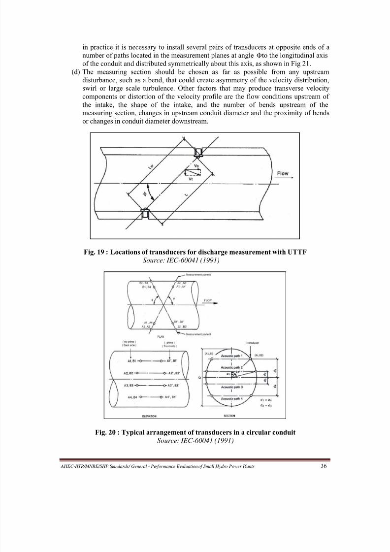
8/20/2019 Performance Evaluation of Small Hydro Power Plants
http://slidepdf.com/reader/full/performance-evaluation-of-small-hydro-power-plants 44/69
AHEC-IITR/MNRE/SHP Standards/ General - Performance Evaluation of Small Hydro Power Plants 36
in practice it is necessary to install several pairs of transducers at opposite ends of a
number of paths located in the measurement planes at angle Φ to the longitudinal axis
of the conduit and distributed symmetrically about this axis, as shown in Fig 21.
(d) The measuring section should be chosen as far as possible from any upstream
disturbance, such as a bend, that could create asymmetry of the velocity distribution,
swirl or large scale turbulence. Other factors that may produce transverse velocity
components or distortion of the velocity profile are the flow conditions upstream ofthe intake, the shape of the intake, and the number of bends upstream of the
measuring section, changes in upstream conduit diameter and the proximity of bends
or changes in conduit diameter downstream.
Fig. 19 : Locations of transducers for discharge measurement with UTTF
Source: IEC-60041 (1991)
Fig. 20 : Typical arrangement of transducers in a circular conduit
Source: IEC-60041 (1991)
8/20/2019 Performance Evaluation of Small Hydro Power Plants
http://slidepdf.com/reader/full/performance-evaluation-of-small-hydro-power-plants 45/69
AHEC-IITR/MNRE/SHP Standards/ General - Performance Evaluation of Small Hydro Power Plants 37
(e) Measurement of discharge using a single path in one or two measuring planes is not
permitted by the Standard.
(f) If two acoustic planes with four paths each are used, then there should be a straight
length of upstream conduit between the measuring section and any important
irregularity of at least ten conduit diameters. Similarly, there should be a straight
length of at least three conduit diameters between the measuring section and any
important downstream irregularity.(g) A single acoustic plane with four paths located downstream of a straight length of
twenty conduit diameters or more, providing a uniform flow distribution in the
measuring section, is also acceptable.
(h) It should be possible to empty the penstock to allow laying out of transducer
locations, drilling of holes in the penstock, fixing the transducers and aligning them.
(Although this process can be carried out in hot condition, that is, without stopping
water flow in the penstock, the techniques used are very difficult and expensive).
(i) Flow velocity and diameter of the conduit shall be large enough to permit an accurate
determination of the difference in acoustic pulse transit times taking into account the
accuracy of the timer. Measurements with flow velocities less than 1.5 m/s and
diameters of conduits less than 0.8 m should be avoided.
(j) Bubbles, sediment and acoustic noise may disrupt the operation of the acoustic flowmeasurement system and a measuring section involving any of them should be
avoided.
Fig. 21 : Locations for measurement of dimension D
Source: IEC-60041 (1991)
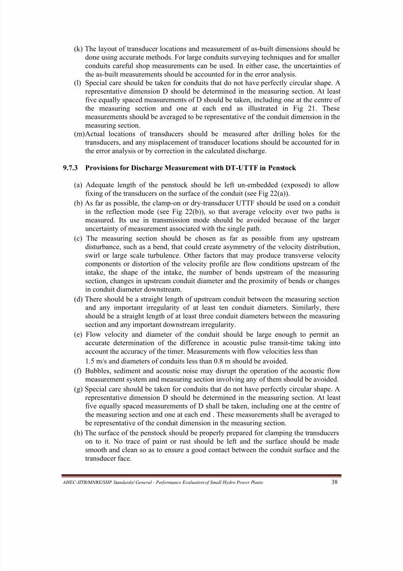
8/20/2019 Performance Evaluation of Small Hydro Power Plants
http://slidepdf.com/reader/full/performance-evaluation-of-small-hydro-power-plants 46/69
AHEC-IITR/MNRE/SHP Standards/ General - Performance Evaluation of Small Hydro Power Plants 38
(k) The layout of transducer locations and measurement of as-built dimensions should be
done using accurate methods. For large conduits surveying techniques and for smaller
conduits careful shop measurements can be used. In either case, the uncertainties of
the as-built measurements should be accounted for in the error analysis.
(l) Special care should be taken for conduits that do not have perfectly circular shape. A
representative dimension D should be determined in the measuring section. At least
five equally spaced measurements of D should be taken, including one at the centre ofthe measuring section and one at each end as illustrated in Fig 21. These
measurements should be averaged to be representative of the conduit dimension in the
measuring section.
(m) Actual locations of transducers should be measured after drilling holes for the
transducers, and any misplacement of transducer locations should be accounted for in
the error analysis or by correction in the calculated discharge.
9.7.3 Provisions for Discharge Measurement with DT-UTTF in Penstock
(a) Adequate length of the penstock should be left un-embedded (exposed) to allow
fixing of the transducers on the surface of the conduit (see Fig 22(a)).
(b) As far as possible, the clamp-on or dry-transducer UTTF should be used on a conduit
in the reflection mode (see Fig 22(b)), so that average velocity over two paths is
measured. Its use in transmission mode should be avoided because of the larger
uncertainty of measurement associated with the single path.
(c) The measuring section should be chosen as far as possible from any upstream
disturbance, such as a bend, that could create asymmetry of the velocity distribution,
swirl or large scale turbulence. Other factors that may produce transverse velocity
components or distortion of the velocity profile are flow conditions upstream of the
intake, the shape of the intake, the number of bends upstream of the measuring
section, changes in upstream conduit diameter and the proximity of bends or changes
in conduit diameter downstream.
(d) There should be a straight length of upstream conduit between the measuring sectionand any important irregularity of at least ten conduit diameters. Similarly, there
should be a straight length of at least three conduit diameters between the measuring
section and any important downstream irregularity.
(e) Flow velocity and diameter of the conduit should be large enough to permit an
accurate determination of the difference in acoustic pulse transit-time taking into
account the accuracy of the timer. Measurements with flow velocities less than
1.5 m/s and diameters of conduits less than 0.8 m should be avoided.
(f) Bubbles, sediment and acoustic noise may disrupt the operation of the acoustic flow
measurement system and measuring section involving any of them should be avoided.
(g) Special care should be taken for conduits that do not have perfectly circular shape. A
representative dimension D should be determined in the measuring section. At leastfive equally spaced measurements of D shall be taken, including one at the centre of
the measuring section and one at each end . These measurements shall be averaged to
be representative of the conduit dimension in the measuring section.
(h) The surface of the penstock should be properly prepared for clamping the transducers
on to it. No trace of paint or rust should be left and the surface should be made
smooth and clean so as to ensure a good contact between the conduit surface and the
transducer face.

8/20/2019 Performance Evaluation of Small Hydro Power Plants
http://slidepdf.com/reader/full/performance-evaluation-of-small-hydro-power-plants 47/69
AHEC-IITR/MNRE/SHP Standards/ General - Performance Evaluation of Small Hydro Power Plants 39
(a) Adequate length of penstock left un-embedded for installing transducers
(b) Transducers of UTTF clamped on a penstock in reflection mode
Fig. 22 : Measurement of discharge with DT-UTTF
9.7.4 Provisions for Discharge Measurement with WT-UTTF in Open Channel
Reference: IEC – 60041 (1991), Appendix J
(a) The measuring section of the open channel should be chosen as far as possible from
any upstream disturbance, such as a bend in the channel that could create asymmetry
of the velocity distribution across the width of the channel, swirl, or large scales
turbulence.
(b) The channel cross-section both upstream and downstream of section should be
uniform, as a change in cross-section may produce transverse velocity components
and distortion of the velocity profile.
(c) There should be a straight length of the upstream channel, between the measuring
section and any important irregularity, of at least ten times the channel width.
Similarly, there should be a straight length of at least three times the channel width
between the measuring section and any important downstream irregularity.
(d) A representative value of the channel width shall be determined in the measuring
section. Measurements shall be made at least at three cross-sections: one at the centre
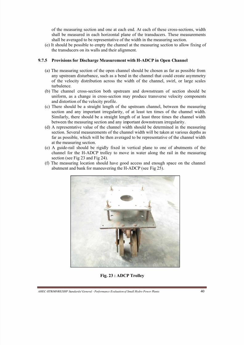
8/20/2019 Performance Evaluation of Small Hydro Power Plants
http://slidepdf.com/reader/full/performance-evaluation-of-small-hydro-power-plants 48/69
AHEC-IITR/MNRE/SHP Standards/ General - Performance Evaluation of Small Hydro Power Plants 40
of the measuring section and one at each end. At each of these cross-sections, width
shall be measured in each horizontal plane of the transducers. These measurements
shall be averaged to be representative of the width in the measuring section.
(e) It should be possible to empty the channel at the measuring section to allow fixing of
the transducers on its walls and their alignment.
9.7.5 Provisions for Discharge Measurement with H-ADCP in Open Channel
(a) The measuring section of the open channel should be chosen as far as possible from
any upstream disturbance, such as a bend in the channel that could create asymmetry
of the velocity distribution across the width of the channel, swirl, or large scales
turbulence.
(b) The channel cross-section both upstream and downstream of section should be
uniform, as a change in cross-section may produce transverse velocity components
and distortion of the velocity profile.
(c) There should be a straight length of the upstream channel, between the measuring
section and any important irregularity, of at least ten times of the channel width.
Similarly, there should be a straight length of at least three times the channel width
between the measuring section and any important downstream irregularity.(d) A representative value of the channel width should be determined in the measuring
section. Several measurements of the channel width will be taken at various depths as
far as possible, which will be then averaged to be representative of the channel width
at the measuring section.
(e) A guide-rail should be rigidly fixed in vertical plane to one of abutments of the
channel for the H-ADCP trolley to move in water along the rail in the measuring
section (see Fig 23 and Fig 24).
(f) The measuring location should have good access and enough space on the channel
abutment and bank for maneuvering the H-ADCP (see Fig 25).
Fig. 23 : ADCP Trolley
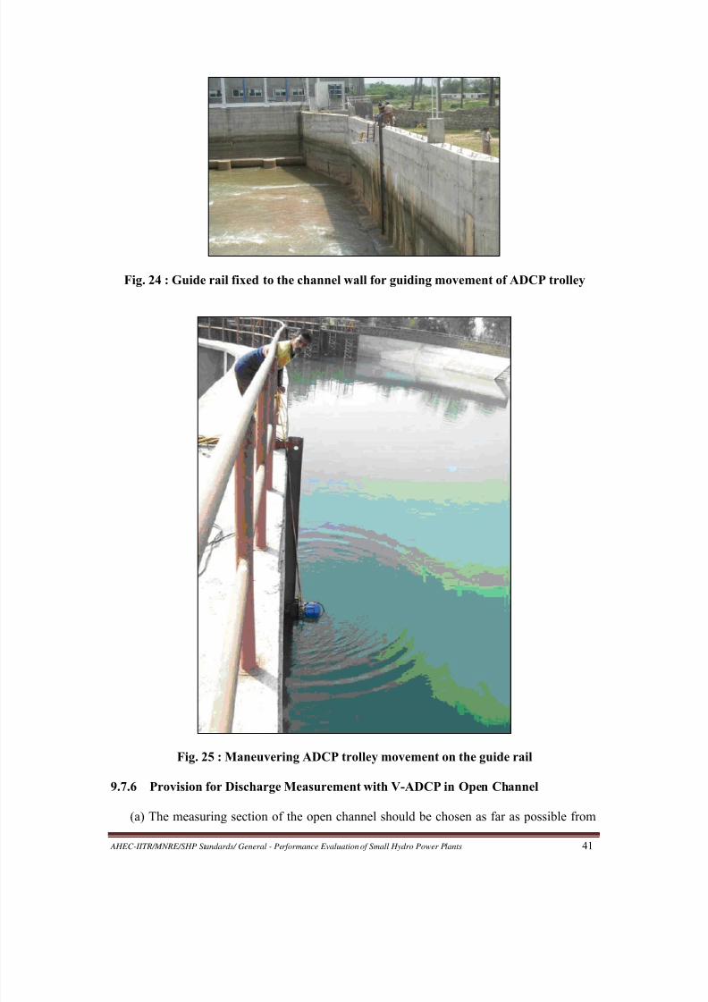
8/20/2019 Performance Evaluation of Small Hydro Power Plants
http://slidepdf.com/reader/full/performance-evaluation-of-small-hydro-power-plants 49/69
AHEC-IITR/MNRE/SHP Standards/ General - Performance Evaluation of Small Hydro Power Plants 41
Fig. 24 : Guide rail fixed to the channel wall for guiding movement of ADCP trolley
Fig. 25 : Maneuvering ADCP trolley movement on the guide rail
9.7.6 Provision for Discharge Measurement with V-ADCP in Open Channel
(a) The measuring section of the open channel should be chosen as far as possible from
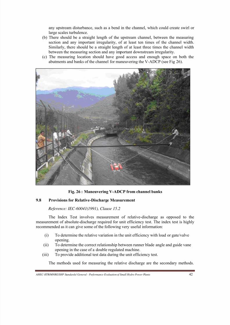
8/20/2019 Performance Evaluation of Small Hydro Power Plants
http://slidepdf.com/reader/full/performance-evaluation-of-small-hydro-power-plants 50/69
AHEC-IITR/MNRE/SHP Standards/ General - Performance Evaluation of Small Hydro Power Plants 42
any upstream disturbance, such as a bend in the channel, which could create swirl or
large scales turbulence.
(b) There should be a straight length of the upstream channel, between the measuring
section and any important irregularity, of at least ten times of the channel width.
Similarly, there should be a straight length of at least three times the channel width
between the measuring section and any important downstream irregularity.
(c) The measuring location should have good access and enough space on both theabutments and banks of the channel for maneuvering the V-ADCP (see Fig 26).
Fig. 26 : Maneuvering V-ADCP from channel banks
9.8 Provisions for Relative-Discharge Measurement
Reference: IEC-60041(1991), Clause 15.2
The Index Test involves measurement of relative-discharge as opposed to the
measurement of absolute-discharge required for unit efficiency test. The index test is highly
recommended as it can give some of the following very useful information:
(i) To determine the relative variation in the unit efficiency with load or gate/valve
opening.
(ii) To determine the correct relationship between runner blade angle and guide vane
opening in the case of a double regulated machine.
(iii) To provide additional test data during the unit efficiency test.
The methods used for measuring the relative discharge are the secondary methods.
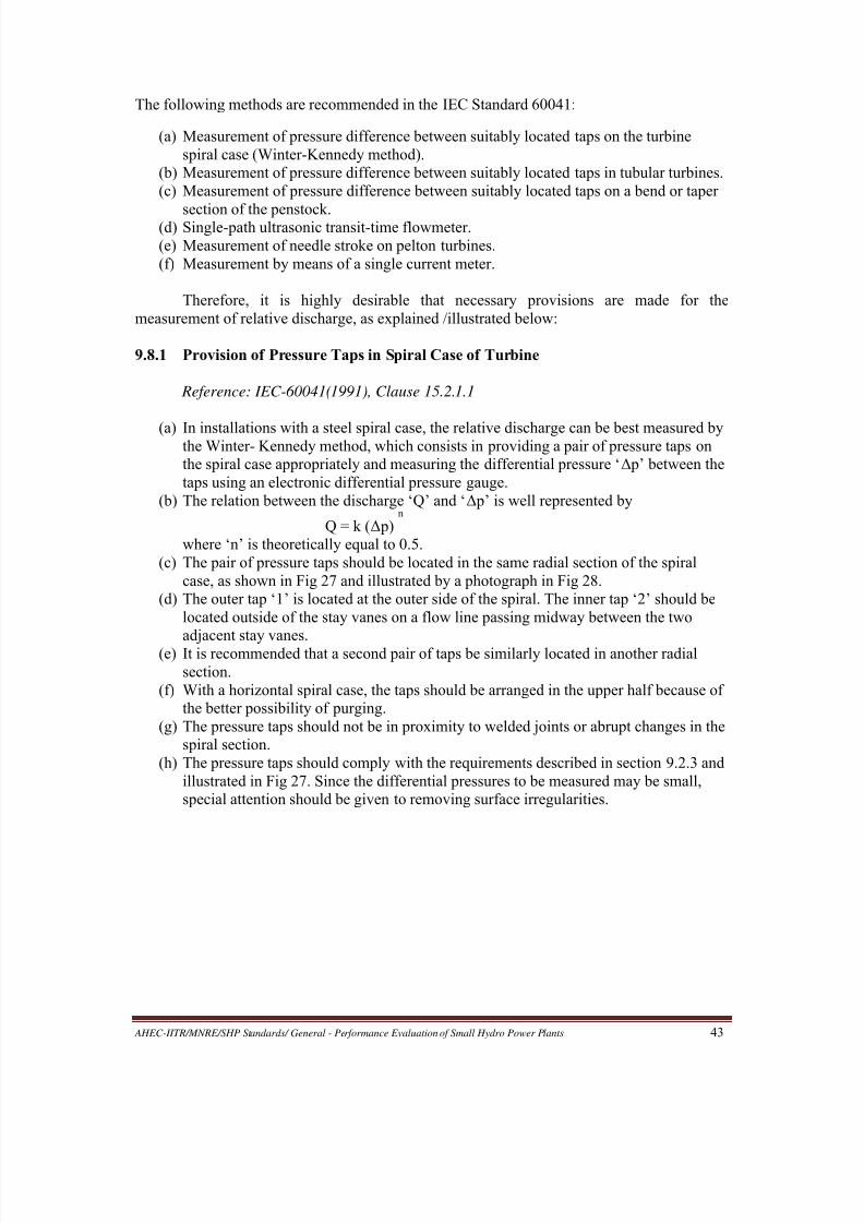
8/20/2019 Performance Evaluation of Small Hydro Power Plants
http://slidepdf.com/reader/full/performance-evaluation-of-small-hydro-power-plants 51/69
AHEC-IITR/MNRE/SHP Standards/ General - Performance Evaluation of Small Hydro Power Plants 43
The following methods are recommended in the IEC Standard 60041:
(a) Measurement of pressure difference between suitably located taps on the turbine
spiral case (Winter-Kennedy method).
(b) Measurement of pressure difference between suitably located taps in tubular turbines.
(c) Measurement of pressure difference between suitably located taps on a bend or taper
section of the penstock.(d) Single-path ultrasonic transit-time flowmeter.
(e) Measurement of needle stroke on pelton turbines.
(f) Measurement by means of a single current meter.
Therefore, it is highly desirable that necessary provisions are made for the
measurement of relative discharge, as explained /illustrated below:
9.8.1 Provision of Pressure Taps in Spiral Case of Turbine
Reference: IEC-60041(1991), Clause 15.2.1.1
(a) In installations with a steel spiral case, the relative discharge can be best measured bythe Winter- Kennedy method, which consists in providing a pair of pressure taps on
the spiral case appropriately and measuring the differential pressure ‘Δ p’ between the
taps using an electronic differential pressure gauge.
(b) The relation between the discharge ‘Q’ and ‘Δ p’ is well represented by
Q = k (Δ p)n
where ‘n’ is theoretically equal to 0.5.
(c) The pair of pressure taps should be located in the same radial section of the spiral
case, as shown in Fig 27 and illustrated by a photograph in Fig 28.
(d) The outer tap ‘1’ is located at the outer side of the spiral. The inner tap ‘2’ should be
located outside of the stay vanes on a flow line passing midway between the two
adjacent stay vanes.(e) It is recommended that a second pair of taps be similarly located in another radial
section.
(f) With a horizontal spiral case, the taps should be arranged in the upper half because of
the better possibility of purging.
(g) The pressure taps should not be in proximity to welded joints or abrupt changes in the
spiral section.
(h) The pressure taps should comply with the requirements described in section 9.2.3 and
illustrated in Fig 27. Since the differential pressures to be measured may be small,
special attention should be given to removing surface irregularities.
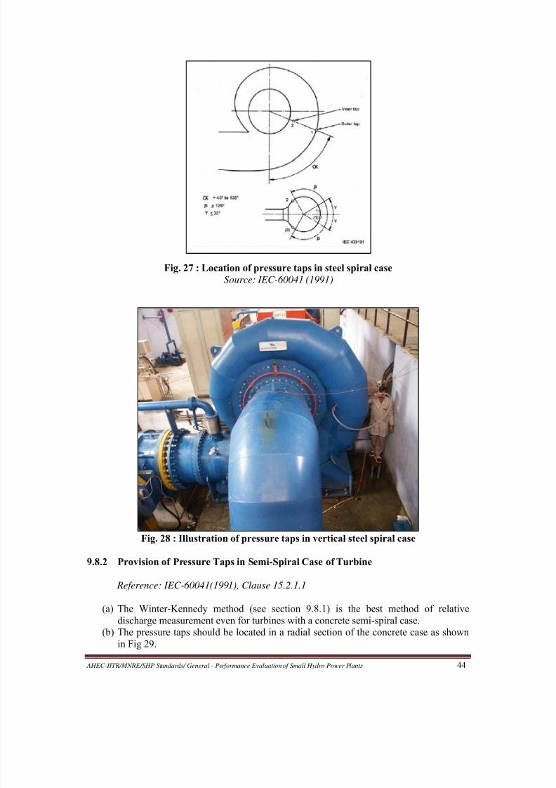
8/20/2019 Performance Evaluation of Small Hydro Power Plants
http://slidepdf.com/reader/full/performance-evaluation-of-small-hydro-power-plants 52/69
AHEC-IITR/MNRE/SHP Standards/ General - Performance Evaluation of Small Hydro Power Plants 44
Fig. 27 : Location of pressure taps in steel spiral case
Source: IEC-60041 (1991)
Fig. 28 : Illustration of pressure taps in vertical steel spiral case
9.8.2 Provision of Pressure Taps in Semi-Spiral Case of Turbine
Reference: IEC-60041(1991), Clause 15.2.1.1
(a) The Winter-Kennedy method (see section 9.8.1) is the best method of relative
discharge measurement even for turbines with a concrete semi-spiral case.
(b) The pressure taps should be located in a radial section of the concrete case as shown
in Fig 29.
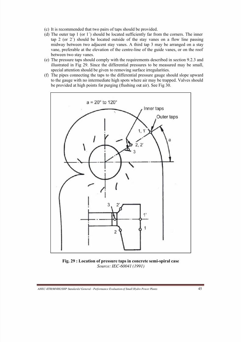
8/20/2019 Performance Evaluation of Small Hydro Power Plants
http://slidepdf.com/reader/full/performance-evaluation-of-small-hydro-power-plants 53/69
AHEC-IITR/MNRE/SHP Standards/ General - Performance Evaluation of Small Hydro Power Plants 45
(c) It is recommended that two pairs of taps should be provided.
(d) The outer tap 1 (or 1´) should be located sufficiently far from the corners. The inner
tap 2 (or 2´) should be located outside of the stay vanes on a flow line passing
midway between two adjacent stay vanes. A third tap 3 may be arranged on a stay
vane, preferable at the elevation of the centre-line of the guide vanes, or on the roof
between two stay vanes.
(e) The pressure taps should comply with the requirements described in section 9.2.3 andillustrated in Fig 29. Since the differential pressures to be measured may be small,
special attention should be given to removing surface irregularities.
(f) The pipes connecting the taps to the differential pressure gauge should slope upward
to the gauge with no intermediate high spots where air may be trapped. Valves should
be provided at high points for purging (flushing out air). See Fig 30.
Fig. 29 : Location of pressure taps in concrete semi-spiral case
Source: IEC-60041 (1991)

8/20/2019 Performance Evaluation of Small Hydro Power Plants
http://slidepdf.com/reader/full/performance-evaluation-of-small-hydro-power-plants 54/69
AHEC-IITR/MNRE/SHP Standards/ General - Performance Evaluation of Small Hydro Power Plants 46
Fig 30 : Upward slopping pipes and valves for purging
9.8.3 Provision of Pressure Taps in Tubular Turbines
Reference: IEC-60041(1991), Clause 15.2.1.3
(a) In application of the differential pressure method of measuring relative discharge
through a bulb turbine, the taps may be located as shown in Fig 31.
(b) It is recommended that two pairs of pressure taps should be provided.
(c) The tap for higher pressure may be arranged at the stagnation point of the bulb (point
1) or of the access shaft (point 1´) and tap for lower pressure should be located on the
wall directly upstream from the guide vanes, however with sufficient distance from
their profile nose at maximum guide vane opening (point 2 or 2´).(d) Discharge may be assumed proportional to the square root of the differential pressure.
(e) For all other types of tubular turbines (e.g. pit turbine) analogous application may be
made.
(f) The pressure taps used should comply with the requirements described in section
9.2.3 . Since the differential pressures to be measured may be small, special attention
should be given to removing surface irregularities.
9.8.4 Provision of Pressure Taps in Taper Section or Bend in Penstock
Reference: IEC-60041(1991), Clauses 15.2.1.2 & 15.2.3.3
(a) In case where the provisions described in sections 9.8.1,9. 8.2 or 9.8.3 above donot apply or are not feasible, relative discharge can be obtained by providing a
pair of pressure taps in a convergent section of the penstock and measuring the
differential pressure between the taps.
(b) Discharge may be assumed proportional to the square root of the differential
pressure.
(c) Two pressure taps are required to be located, one each at two cross-sections of
different areas. The most stable pressure difference will be obtained if both taps
are located on the converging part of the pipe. However, if the differential

8/20/2019 Performance Evaluation of Small Hydro Power Plants
http://slidepdf.com/reader/full/performance-evaluation-of-small-hydro-power-plants 55/69
AHEC-IITR/MNRE/SHP Standards/ General - Performance Evaluation of Small Hydro Power Plants 47
pressure thus obtained is not large enough, it may be preferable to locate one tape
a short distance upstream of the convergent section and the second one not less
than half a diameter downstream of the convergent section.
(d) If a convergent section of penstock is not available or accessible for the purpose as
above, then the taps may be provided in a divergent section of the penstock or a
bend in the penstock.
(e) The pressure taps used should comply with the requirements described in section9.2.3 and illustrated in Fig 31. Since the differential pressures to be measured may
be small, special attention should be given to removing surface irregularities.
Fig. 31 : Location of taps in bulb turbine
Source: IEC-60041 (1991)
9.8.5 Provisions for Alternative Methods of Discharge Measurement
Reference: IEC-60041(1991), Clauses 15.2.2, 15.2.3.1 and 15.2.3.2
In cases where the provisions described in sections 8.1, 8.2, 8.3 or 8.4 above do not
apply or are not feasible, necessary provision should be made for at least one of the
alternative methods of relative discharge measurement as described below:

8/20/2019 Performance Evaluation of Small Hydro Power Plants
http://slidepdf.com/reader/full/performance-evaluation-of-small-hydro-power-plants 56/69
AHEC-IITR/MNRE/SHP Standards/ General - Performance Evaluation of Small Hydro Power Plants 48
(a) Relative discharge measurement by acoustic method is suitable due to the good
repeatability of measurements and good linear characteristic. One single-path
system or a double-plane single-path system, as shown in Fig 32 and Fig 33,
respectively, may be sufficient.
Fig. 32 : Acoustic method of discharge measurement - Single path system
Source: IEC-60041 (1991)
Fig. 33 : Acoustic method of discharge measurement - Double plane single path system
Source: IEC-60041 (1991)
(b) The stroke of the needle of a Pelton turbine may be used to give relative
discharge, provided that the discharge/stroke characteristic shape has been
checked by tests on a homologous model of the turbine. Great care should be
taken to ensure that during the test the needle, nozzle and support vanes areclean and in good order.
(c) Relative discharge can also be measured using one single current meter suitably
located in the open channel or conduit, as the case may be.
9.9 Provisions for Electrical Power Measurement
Reference: IEC-60041(1991), Clause 12

8/20/2019 Performance Evaluation of Small Hydro Power Plants
http://slidepdf.com/reader/full/performance-evaluation-of-small-hydro-power-plants 57/69
AHEC-IITR/MNRE/SHP Standards/ General - Performance Evaluation of Small Hydro Power Plants 49
Electrical power output of generator is required to be measured as one of the
parameters, both in the efficiency test and the maximum power output test. Certain provisions
are recommended below to facilitate this measurement and to achieve good accuracy. The
same provisions also facilitate error checks on panel meters.
9.9.1 Test Terminal Block
(a) A test terminal block (TTB), which is an inexpensive and standard control-panel
accessory (see Fig 34), should be provided on every metering panel.
(b) The TTB should be provided on the front, usually near the bottom, of the control
panel (see Fig 35).
(c) The TTB shall be appropriately wired to make available the current transformer
(CT) and voltage transformer (VT) outputs on it. This will enable connecting a
reference meter during testing from outside, without opening the panel or stopping
the machine or switching off the machine breaker (see Fig 36).
(d) The TTB should be of 3-phase 3-wire or of 3-phase 4-wire type, depending on the
nature of the machine output.
(e) Locating the TTB inside a control panel should be avoided, because in that case a
reference meter can be connected at the TTB only after opening the panel andworking inside the live panel, which can be a safety hazard.
(f) It should be noted that sliding-link terminals, used as a standard practice to
terminate CT outputs inside control panels, are not a substitute for the TTB on the
front of the control panels, because a reference meter can be connected at the
sliding-link terminals only after opening the panel and working inside the live
panel, which can again be a safety hazard.
Fig. 34 : A Sample of TTB

8/20/2019 Performance Evaluation of Small Hydro Power Plants
http://slidepdf.com/reader/full/performance-evaluation-of-small-hydro-power-plants 58/69
AHEC-IITR/MNRE/SHP Standards/ General - Performance Evaluation of Small Hydro Power Plants 50
Fig. 35 : TTB (shown with cover in place) fitted on the front of a control panel
Fig. 36 : Reference meter connected at TTB without opening the control panel
9.9.2 Instruments and Measuring Transformers
Reference: IEC-60041(1991), Clause 12.1.1.2.1
(a) The watt-meters connected for measuring the generator output power should be of
accuracy class 0.2 or better.
(b) The voltmeters and ammeters connected for measuring the generator voltages and
currents should be of accuracy class 0.5 or better.
(c) The measuring transformers, that is, the current and voltage transformers,
connected at the output of the generator should be of accuracy class 0.2 or better.

8/20/2019 Performance Evaluation of Small Hydro Power Plants
http://slidepdf.com/reader/full/performance-evaluation-of-small-hydro-power-plants 59/69
AHEC-IITR/MNRE/SHP Standards/ General - Performance Evaluation of Small Hydro Power Plants 51
ANNEXURE 1
FORMAT OF POWER STATION DATA TO BE SUPPLIED BY OWNER
(1) To be provided by the Power Station Owner interested in Performance Evaluation to the
Evaluating Agency.
(2) Equipment supplier/contractor may be consulted to obtain relevant information/drawingif not available with the owner
(3) Please do not leave any column blank, write NA for Not Applicable and DNA for Data
Not Available.
(4) Please note that unless the mandatory information (wherever indicated) is provided,
evaluation will not be taken up.
A. GENERAL (mandatory information)
Name of Power Station:
Owner of Power Station: (with tel/fax/email and postal address)
Location (Enclose location/route map)
Nearest Town with Distance:District:
State:
Longitude:
Latitude:
Altitude:
Nearest Guest-House/Hotel (with address and distance):
Details of plant
Type of Power Station (Run-of-River/Dam based/Canal based):
Source of Water:
No. of Generating Units with Capacities:
Maximum and minimum head:
Commissioning Date (for each unit):
B. GENERATING UNITS (mandatory information)
1. Turbine
Type:
Shaft (Vertical/Horizontal):
Make:
Rated Head:
Rated Discharge:
Rated Power Output:
Rated Speed:
Speed Increaser Used (None/Gear Box/others):
Flywheel Provided? (Yes/No):
Pressure Taps Provided? (Yes/No):
If yes,
Number:
Size:

8/20/2019 Performance Evaluation of Small Hydro Power Plants
http://slidepdf.com/reader/full/performance-evaluation-of-small-hydro-power-plants 60/69
AHEC-IITR/MNRE/SHP Standards/ General - Performance Evaluation of Small Hydro Power Plants 52
Locations:
(Enclose drawing/photograph)
2. Generator
Make:
Type (Synchronous / Induction): (select one)
Rated Speed:
Generator Ratings: ______ kW, ____ pf, ____ kVA, ____ Hz,
____ kV, Y or D connected stator windings
Designed Overloading (%):
Run-away Speed:
Excitation System (Brushless/Static/Brush-type) : (select one) Exciter Ratings:
3. Voltage Regulator
Type (Digital / Analog): (select one)
Make:Response Time:
Sensitivity:
4. Governor
Type (Digital /Analog/PLC): (select one)
Make:
Response Time:
Sensitivity:
5. Main Inlet ValveMake:
Type:
Closing time:
6. Guide Vanes/Wicket Gates/Nozzles
Device (Guide vanes/wicket gates/Nozzles): (select one)
Number:
Closing time:
7. Efficiency of Generating Units
(Enclose efficiency curves/data for turbine and generator from the manufacturers)
8. Any problem observed? If yes, give details:
Turbine:
Generator:
Main Inlet Valve:
Speed Increaser:

8/20/2019 Performance Evaluation of Small Hydro Power Plants
http://slidepdf.com/reader/full/performance-evaluation-of-small-hydro-power-plants 61/69
AHEC-IITR/MNRE/SHP Standards/ General - Performance Evaluation of Small Hydro Power Plants 53
Governor:
Exciter:
Voltage Regulator:
Bearings:
Others:
C. WATER CONDUCTOR SYSTEM (Enclose relevant drawings for applicable components) (Mandatory information)
1 Details of weir/Barrage/Dam: Type, dimensions, inlet gate, design discharge for
power generation, various levels
design, flood discharge
2 Details of desilting tank: Discharge, dimensions, number of outlets and sizes
3 Head-Race Channel/tunnel/Pipe: Length, cross section (Width, depth, side slopes)
lining, discharge
4 Details of forebay tank: dimensions, number of outlets, sizes, trash rack arrangement,
5 Details of surge tank: Type and dimensions,
6 Tail-Race Channel: Length, cross section (Width, depth, side slopes) lining, discharge
7 Designed Discharge for power house for all units(in m3/s):8 Single Intake or Individual Intakes for Machines:
9 Number and Type of Intake Gates:
Type:
No. of intake gates per turbine
Total no. of intake gates
Size
Type of hoisting
10. Number and Type of Draft Tube (DT) Gates:
Type:
No. of DT gates per turbine:
Total no. of DT gates:
Size
Type of hoisting
11. Common Penstock
Length:
Inside Diameter:
Thickness:
Material:
No of bends
No of Expansion Joints
12. Individual Penstocks
Length:
Inside Diameter:
Thickness (various):
Material:
13. Spilling Arrangement, dimensions, lauout and Discharge Capacity

8/20/2019 Performance Evaluation of Small Hydro Power Plants
http://slidepdf.com/reader/full/performance-evaluation-of-small-hydro-power-plants 62/69
AHEC-IITR/MNRE/SHP Standards/ General - Performance Evaluation of Small Hydro Power Plants 54
D. DISCHARGE MEASUREMENT PROVISIONS (mandatory information)
1. Do you measure discharge? (Yes / No):
If no, how do you know the discharge?
If yes,
How frequently?
By what method?
Location of Measurement:
Details of Instrument/Method:
(Enclose drawing / photograph)
2. Do you have provision for relative discharge measurement? (Yes/No):
If yes,
Method used (Taper section/Winter-Kennedy/others):
Details: (Enclose drawing/photograph)
E. HEAD / LEVEL MEASUREMENT PROVISIONS (mandatory information)
1. Do you have provisions for head or pressure measurement? (Yes / No):
If yes,
Location:
Method/ instrument Used:
Size of pressure taps:
Location of pressure taps:
(Enclose drawing / photograph)
2. Do you have provisions for measurement of free water level? (Yes / No):
If yes,Locations:
Method/ Instrument Used:
(Enclose drawing / photograph)
3. Whether reference elevations marked? (Yes / No):
If yes,
Location (Machine floor/others):
Levels above MSL (in m):
4. Whether elevation of Centre-line of Penstock Marked? (Yes / No):
If yes, its level (in m):
5. Whether elevation of Centre-line of Turbine Marked? (Yes / No):
If yes, its level (in m):

8/20/2019 Performance Evaluation of Small Hydro Power Plants
http://slidepdf.com/reader/full/performance-evaluation-of-small-hydro-power-plants 63/69

8/20/2019 Performance Evaluation of Small Hydro Power Plants
http://slidepdf.com/reader/full/performance-evaluation-of-small-hydro-power-plants 64/69
AHEC-IITR/MNRE/SHP Standards/ General - Performance Evaluation of Small Hydro Power Plants 56
6. Details of CTs are shown in table A3 below:
Table A3 : Details of CTs
Sl.
No.
Location Measuring or
Protection CT?
CT Ratio Accuracy Class
6.Details of Voltage (Potential) Transformers are shown in table A4 below:
Table A4 : Details of Voltage (Potential) Transformers
Sl.
No.
Location Measuring or
Protection V.T.?
V.T. Ratio Accuracy
Class
H. PROTECTION SYSTEM (Enclose relevant panel drawings)
1. Details of Measuring Relays are shown in table A5 below:
Table A5 : Details of Measuring Relays
S. No. Name of Panel Name of Relay Make Model
2. Details of Auxiliary / Master/Trip Relays are shown in table A6 below
Table A6 : Details of Auxiliary / Master/Trip Relays
S.
No.
Name of Panel Name of Relay Make Model

8/20/2019 Performance Evaluation of Small Hydro Power Plants
http://slidepdf.com/reader/full/performance-evaluation-of-small-hydro-power-plants 65/69
AHEC-IITR/MNRE/SHP Standards/ General - Performance Evaluation of Small Hydro Power Plants 57
3. Details of Circuit Breakers are shown in table A7 below
Table A7 : Details of Circuit Breakers
S.
No.
Breaker Name Breaker Type
(Air/Oil/SF6)
Breaker
Location
Make Model
4. Details of Fault Annunciators (FA) are shown in table A8 below
Table A8 : Details of Fault Annunciators
S.
No.
Name of Panel Microprocessor
or
Relay type?
Make of
FA
No. of Facia Windows
Total number Numberused
I. Details of station / plant auxiliaries are shown in table A9 below:
Table A9 : Details of station / plant auxiliaries
S.
No.
Name of Auxiliary Particulars/Ratings/Make/Quantity
1. Station AC Supply
2. Station DC Supply
3. Oil Pumping Units
4. Bearing Cooling System
5. Generator Cooling System
6. Transformer Cooling System
7. Vacuum Pumps
8. Air Compressors
9. Drainage System
10. Dewatering System
11. Equipment Handling Crane ( spanand Capacity main/auxiliary)
12. Hoists
13.Power house dimension( Length,
Width and height above machine
14. (Others)
J. DETAILS OF ANY OTHER EQUIPMENT not covered above (like SCADA) or
any other information relevant to the Performance testing of your Power Station:

8/20/2019 Performance Evaluation of Small Hydro Power Plants
http://slidepdf.com/reader/full/performance-evaluation-of-small-hydro-power-plants 66/69
AHEC-IITR/MNRE/SHP Standards/ General - Performance Evaluation of Small Hydro Power Plants 58
K. FLOW DURATION CURVE: Enclose a photocopy of the flow duration curve and
data as included in the DPR (mandatory information).
L . TESTS CONDUCTED AT SITE, IF ANY (Enclose report)
M. DATA REGARDING CONFORMITY TO STANDARDS (mandatory information)
Data regarding conformity to standards shall be as shown in table A10 below:
Table A10 : Data regarding conformity to standards
S.
No.
Name of
equipment
Make Standard(s)
to which
equipment
conforms
Evidence of conformity to standard(s) a
Certificate of
manufacturer b
Test
report c
Certification
mark on theequipment
d
(1) (2) (3) (4) (5) (6) (7)
1. Turbines
2. Generators
3. Power
Transformers
4. CTs
5. VTs
6. Protective
Relays
7. HT Circuit
Breakers
8. LT Circuit
Breakers
9. PLC
10. SCADA System
11. Governor12. Excitation
System
13. AVR
14. Auto
Synchronizer
15. Panel Meters
16. Motors
17. Cables
18. Batteries
19. Pumps
20. Crane
21. (Others)
aAt least one of the three evidences should be there. So at least one of the three columns,
namely (5), (6) and (7), should have ‘YES’. Your YES statement will be verified by the test
team at site. b
Certificate of manufacturer declaring that the equipment conforms to the standard stated in
column (4).

8/20/2019 Performance Evaluation of Small Hydro Power Plants
http://slidepdf.com/reader/full/performance-evaluation-of-small-hydro-power-plants 67/69
AHEC-IITR/MNRE/SHP Standards/ General - Performance Evaluation of Small Hydro Power Plants 59
c Test report for the equipment mentioning clearly that the equipment conforms to the
standard stated in column (4).d The certification mark by the standards organization such as BIS showing that the
equipment conforms to the standard stated in column (4).
N. DETAILS FOR CLEARANCES OBTAINED FOR PROJECT (mandatory
information)Details for clearances obtained for project shall be as per table A11 below
Table A11 : Details for clearances obtained for project
Name of the Clearance Date of
application/submission
Date of
approval/clearance
1. Power Purchase Agreement
2. Pollution Control
3. Land Acquisition
(a) Forest Land
(b) Private Land
(c) Gram Panchayat
4. State Irrigation Department
5. Financing Institute (loan)
6. State Nodal Agency for Techno-
Economic Clearance
7. Labour
8. Explosives License
9. Wireless Communication
10. Wild life
11. Fisheries
12. Archaeology
13. PWD
14. (Any other clearance)
O. PERMANENT /TEMPORAY BENCH MARK AT POWER HOUSE
Location:
Elevation( in m)
P. CHECK LIST OF ENCLOSURES (Please fill in enclosure numbers, such as I, II
etc. and mark the same on the enclosures) (mandatory information)
Check list of enclosures shall be as per table A12 below:
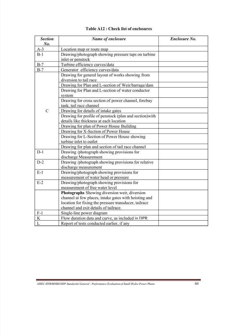
8/20/2019 Performance Evaluation of Small Hydro Power Plants
http://slidepdf.com/reader/full/performance-evaluation-of-small-hydro-power-plants 68/69
AHEC-IITR/MNRE/SHP Standards/ General - Performance Evaluation of Small Hydro Power Plants 60
Table A12 : Check list of enclosures
Section
No.
Name of enclosure Enclosure No.
A-3 Location map or route map
B-1 Drawing/photograph showing pressure taps on turbine
inlet or penstockB-7 Turbine efficiency curves/data
B-7 Generator efficiency curves/data
C
Drawing for general layout of works showing from
diversion to tail race
Drawing for Plan and L-section of Weir/barrage/dam
Drawing for Plan and L-section of water conductor
system
Drawing for cross section of power channel, forebay
tank, tail race channel
Drawing for details of intake gates
Drawing for profile of penstock (plan and section)withdetails like thickness at each location
Drawing for plan of Power House Building
Drawing for X-Section of Power House
Drawing for L-Section of Power House showing
turbine inlet to outlet
Drawing for plan and section of tail race channel
D-1 Drawing /photograph showing provisions for
discharge Measurement
D-2 Drawing /photograph showing provisions for relative
discharge measurement
E-1 Drawing/photograph showing provisions for
measurement of water head or pressureE-2 Drawing/photograph showing provisions for
measurement of free water level
Photographs Showing diversion weir, diversion
channel at few places, intake gates with hoisting and
location for fixing the pressure transducer, tailrace
channel and exit details of tailrace.
F-1 Single-line power diagram
K Flow duration data and curve, as included in DPR
L Report of tests conducted earlier, if any

8/20/2019 Performance Evaluation of Small Hydro Power Plants
http://slidepdf.com/reader/full/performance-evaluation-of-small-hydro-power-plants 69/69
ANNEXURE 2
FORMAT OF GENERATION DATA TO BE SUPPLIED BY OWNER
A. Summary of Month-Wise Actual and Projected Generations
Month
and
Year
Actual Total
Generation
(million units)
Projected
Generation as per
DPR (million units)
Ratio of Actual- to-
Projected Generations
(percent)
Remark
(Above or
below 80%)