pcm2000 manual - bogen communications inc · configuration guide. 2. contents section i
TRANSCRIPT

© 2012 Bogen Communications, Inc.All rights reserved.
Specifications subject to change without notice.54-5019-01C 1209
PCM2000Configuration Guide

2

Contents SECTION I - APPLICATION CONFIGURATIONS ............................................................................................................................4-31
Configuration 1: Page Port Contact Closure/3-Zone/One-Way Paging/Single Amplifier/25 & 70V AC Speakers Setup Drawing........................................................................................................................................................................4 Description ............................................................................................................................................................................5
Configuration 2: Page Port VOX Circuit/3-Zone/One-Way Paging/Single Amplifier/25 & 70V AC Speakers Setup Drawing........................................................................................................................................................................6 Description ............................................................................................................................................................................7
Configuration 3: Loop Start Trunk/3-Zone/One-Way Paging/Single Amplifier/25 & 70V AC Speakers Setup Drawing........................................................................................................................................................................8 Description ............................................................................................................................................................................9
Configuration 4: Ground Start Trunk /3-Zone/One-Way Paging /Single Amplifier/25 & 70V AC Speakers Setup Drawing......................................................................................................................................................................10 Description............................................................................................................................................................................11
Configuration 5: Station Level/Centrex/3-Zone/One-Way Paging/Single Amplifier/25 & 70V AC Speakers Setup Drawing......................................................................................................................................................................12 Description ..........................................................................................................................................................................13
Configuration 6: Extended Paging System Setup Drawing......................................................................................................................................................................14 Description ..........................................................................................................................................................................15
Configuration 7: Two-Way Talk Back Paging System Setup Drawing......................................................................................................................................................................16 Description ..........................................................................................................................................................................17
Configuration 8. Two-Way Talk Back Extended Paging System Setup Drawing......................................................................................................................................................................18 Description ..........................................................................................................................................................................19
Configuration 9: 3-Zone/One-Way Paging/Low-Power System/Self-Amplified Speakers Setup Drawing......................................................................................................................................................................20 Description ..........................................................................................................................................................................21
Configuration 10: 6 Zones/One-Way Paging/Mixed High- & Low-Power Zones/25 & 70V AC Speakers Setup Drawing......................................................................................................................................................................22 Description ..........................................................................................................................................................................23
Configuration 11: Microphone Override Setup Drawing......................................................................................................................................................................24 Description ..........................................................................................................................................................................25
Configuration 12: DFT120 & TAMB2 Wiring Diagram - Ground Start Trunk or Station Level Setup Drawing......................................................................................................................................................................26 Description ..........................................................................................................................................................................27
Configuration 13: Emergency Alert Tones Setup Drawing......................................................................................................................................................................28 Description ..........................................................................................................................................................................29
Configuration 14: Single Amplifier Background Music Line-Level Signal Setup Drawing......................................................................................................................................................................30 Description ..........................................................................................................................................................................30
Configuration 15: Relay Driver Output Setup Drawing......................................................................................................................................................................31 Description ..........................................................................................................................................................................31
SECTION II - Programming ............................................................................................................................................................32-36
System Programming ..................................................................................................................................................................32 Feature Codes and Defaults Chart ........................................................................................................................................33-35 SYS-ID Switch Settings Chart for Additional Satellite Systems ..................................................................................................36
APPENDIX Module Assembly ........................................................................................................................................................................37
3
4
POW
ER
- 1.
5A
OU
T
RT
GN
D
AU
X
GN
D
S1
S2
S3
S4
0
1
SYS
ID
RU
N
PRO
GR
AM
DA
TAL
INK
12V
DC
1.5A
-
IN RT
RTIN R
TIN EM
/SC
+ 1
2VD
C
BO
GE
N
PA
LPB
GM
PA
HPB
GM+
POW
ER
RD
CO
M
+ - RD
A
RD
B
ZO
NE
AZ
ON
E B
ZO
NE
C
OF
F
O
NTA
LKB
AC
K
RTIN RD
C
LO
CA
LB
GM
ZO
NE
A
+ -
ZO
NE
B
+ -Z
ON
E C
LPB
GM
VO
LU
ME
LO
PW
R
HI
PWR
OU
TPU
T
BG
MO
UT
IN
PCM
ZPM
PCM
CPU
+-PC
M P
S2
RT
70V
CO
M
BO
GE
N P
AG
ING
AM
PLI
FIE
R
ZO
NE
A
ZO
NE
B
ZO
NE
C
GLO
BL
BG
M
ZO
NE
C
ZO
NE
B
ZO
NE
A
PBX
PAG
ING
POR
T
T R
1 -
Not
use
d
2 -
Con
tact
Clo
sure
3 -
Dry
aud
io (
R)
4 -
Dry
aud
io (
T)
5 -
Con
tact
Clo
sure
6 -
Not
use
d
CO
NTA
CT
CLO
SU
RE
PCM
TIM
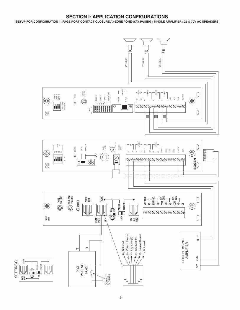
SECTION I: APPLICATION CONFIGURATIONSSETUP FOR CONFIGURATION 1: PAGE PORT CONTACT CLOSURE / 3-ZONE / ONE-WAY PAGING / SINGLE AMPLIFIER / 25 & 70V AC SPEAKERS
SE
TT
ING
S

5
CONFIGURATION 1:PAGE PORT CONTACT CLOSURE / 3-ZONE / ONE-WAY PAGING / SINGLE AMPLIFIER / 25 & 70V AC SPEAKERS
In this configuration, the PCM unit responds to a contact closure on pins 2 & 5 of the TRUNK/PAGE PORT jack on the PCMTIM moduleshorting the +5V source to its ground. When the closure is removed, the page ends. Audio is provided to the system through a separatepair of leads on pins 3 & 4 of the TRUNK/PAGE PORT jack on the PCMTIM module. Pins 1 & 6 are not used in this configuration.
Note: The audio pair (page port) must pass DTMF in order to select a zone.
The required setup includes PCMTIM - PCMCPU - PCMZPM - PCMPS2. Modules must be assembled, from left to right, in this order.
INSTALLATION:STEP 1: Assemble Modules PCMTIM to PCMCPU and to PCMZPM (see Illustration/Instructions on Appendix page 37,
then return to this page and complete the following Steps).
Note: DO NOT connect the PCMPS2 (power supply) at this point.
STEP 2: Connecting Paging Port/Contact Closure from the Telephone System to the PCMTIM Module
• Take the page port audio pair from the telephone system and wire it to the RJ11 TRUNK/PAGE PORT jack to pins 3 & 4 (red andgreen); and the contact closure pair to pins 2 & 5 (black and yellow).
• Use a 4- or 6-pin modular cord to connect the RJ11 to the TRUNK/PAGE PORT jack on the PCMTIM module.
STEP 3: Switch Settings
• Set the slide switches on the PCMTIM module for Page Port Contact Closure: Set the first switch to CC (for Contact Closure) andset the second switch to P/P (for Page Port).
• Set the SYS-ID DIP switches on the PCMCPU module to the OFF position (to the left).• Set the RUN-PROGRAM switch on the PCMCPU module to the RUN mode (up).• Set the Talk Back DIP switches on the PCMZPM module to the OFF position (to the left) for all zones.• Set the OUTPUT switch on the PCMZPM module to the HI-PWR position (down).
STEP 4: Testing your System
• Connect power supply PCMPS2 to the PCMCPU module to either the power jack 12V DC input or wire it to the 12V DCscrew terminals observing polarity.
• At this point all the power LEDs should be lit on each module.• Access the page port from the phone system and verify access tones (double beep) in handset.• At this point, the system should be functioning properly.• Disconnect Power Supply.
STEP 5: Connecting the Paging Amplifier
• Locate the terminals on the PCMCPU module labeled PA IN/RT and wire to the TIP and Ring (T & R) input on the Bogenpaging amplifier (either TPU-Series, GS-Series, or Classic Series amplifiers).
• Locate the terminals on the PCMCPU module labeled PA OUT/RT and wire to COMMON and either the 25 or 70V outputon the paging amplifier.
STEP 6: Connecting 25 & 70V AC Speakers
• Locate the terminals on the PCMZPM module labeled ZONE A. These terminals have two connections marked + and - .Wire your speakers for ZONE ONE to these terminals. Observe polarity (-) to common (+) to selected tap setting.
• Follow the same procedure for the terminals labeled ZONE B for ZONE TWO, and the terminals labeled ZONE Cfor ZONE THREE.
STEP 7: Testing your System
• Connect the power supply PCMPS2 to the PCMCPU module to either the power jack 12V DC input or wire it tothe 12V DC screw terminals, observing polarity.
• Connect the Bogen amplifier to the AC power outlet (120V AC, 60Hz).• Set the volume on your Bogen amplifier to a 1/2 turn.• Access the paging from the telephone system and listen (on the handset) for the confirmation tone (double beep).• Dial 01 to access ZONE ONE and listen (on the handset and also to the speakers) for a pre-announce tone (single beep)
followed by your page (audio).• Follow the same steps for ZONES TWO (02) and THREE (03). Dial [00] for All-Page.• Set the Bogen amplifier to the desired volume level.

6
POW
ER
- 1.
5A
OU
T
RT
GN
D
AU
X
GN
D
S1
S2
S3
S4
0
1
SYS
ID
RU
N
PRO
GR
AM
DA
TAL
INK
12V
DC
1.5A
-
IN RT
RTIN R
TIN EM
/SC
+ 1
2VD
C
BO
GE
N
PA
LPB
GM
PA
HPB
GM+
POW
ER
RD
CO
M
+ - RD
A
RD
B
ZO
NE
AZ
ON
E B
ZO
NE
C
OF
F
O
NTA
LKB
AC
K
RTIN RD
C
LO
CA
LB
GM
ZO
NE
A
+ -
ZO
NE
B
+ -Z
ON
E C
LPB
GM
VO
LU
ME
LO
PW
R
HI
PWR
OU
TPU
T
BG
MO
UT
IN
PCM
ZPM
PCM
CPU
+-PC
M P
S2
RT
70V
CO
M
BO
GE
N P
AG
ING
AM
PLI
FIE
R
ZO
NE
A
ZO
NE
B
ZO
NE
C
GLO
BL
BG
M
ZO
NE
C
ZO
NE
B
ZO
NE
A
PCM
TIM
PBX
PAG
ING
POR
T
T R
1 -
Not
use
d
2 -
Con
tact
Clo
sure
3 -
Dry
aud
io (
R)
4 -
Dry
aud
io (
T)
5 -
Con
tact
Clo
sure
6 -
Not
use
d
SETUP FOR CONFIGURATION 2: PAGE PORT VOX CIRCUIT / 3-ZONE / ONE-WAY PAGING / SINGLE AMPLIFIER / 25 & 70V AC SPEAKERSS
ET
TIN
GS

7
CONFIGURATION 2:PAGE PORT VOX CIRCUIT / 3-ZONE / ONE-WAY PAGING / SINGLE AMPLIFIER / 25 & 70V AC SPEAKERS
This configuration is for Page Ports without Contact Closures. A dry audio pair connected to pins 3 & 4 of the TRUNK/PAGE PORT jackon the PCMTIM module is used to detect audio and activate the system. Paging ends when the VOX timer or default timer times out.Pins 1, 2, 5 & 6 are not used in this configuration.
Note: The audio pair (page port) must pass DTMF in order to select a zone.
The required setup includes: PCMTIM - PCMCPU - PCMZPM - PCMPS2. Modules must be assembled, from left to right, in this order.
INSTALLATION:STEP 1: Assemble Modules PCMTIM to PCMCPU and to PCMZPM (see Illustration/Instructions on Appendix page 37,
then return to this page and complete the following Steps).
Note: DO NOT connect the PCMPS2 (power supply) at this point.
STEP 2: Connecting Paging Port/VOX from the Telephone System to the PCMTIM Module
• Take the page port (VOX) audio pair from the telephone system and wire it to the RJ11 TRUNK/PAGE PORT jack in the PCMTIMmodule to pins 3 & 4 (red and green).
• Use a 4- or 6-pin modular cord to connect the RJ11 to the TRUNK/PAGE PORT jack on the PCMTIM module.
STEP 3: Switch Settings
• Set the slide switches on the PCMTIM module for Page Port VOX Configuration: Set the first switch to VX (for VOX)and set the second switch to P/P (for Page Port).
• Set the SYS-ID DIP switches on the PCMCPU module to the OFF position (to the left).• Set the RUN-PROGRAM switch on the PCMCPU module to the RUN mode (up).• Set the Talk Back DIP switches on the PCMZPM module to the OFF position (to the left) for all zones.• Set the OUTPUT switch on the PCMZPM module to the HI-PWR position (down).
STEP 4: Testing your System
• Connect power supply PCMPS2 to the PCMCPU module to either the power jack 12V DC input or wire it to the 12V DCscrew terminals observing polarity.
• At this point all the power LEDs should be lit on each module.• Access the page port from the phone system and verify access tones (double beep) in handset.• At this point, the system should be functioning properly.• Disconnect Power Supply.
STEP 5: Connecting the Paging Amplifier
• Locate the terminals on the PCMCPU module labeled PA IN/RT and wire to the TIP and Ring (T & R) input on the Bogenpaging amplifier (either TPU-Series, GS-Series, or Classic Series amplifiers).
• Locate the terminals on the PCMCPU module labeled PA OUT/RT and wire to COMMON and either the 25 or 70V outputon the paging amplifier.
STEP 6: Connecting 25 & 70V AC Speakers
• Locate the terminals on the PCMZPM module labeled ZONE A. These terminals have two connections marked + and - .Wire your speakers for ZONE ONE to these terminals. Observe polarity (-) to common (+) to selected tap setting.
• Follow the same procedure for the terminals labeled ZONE B for ZONE TWO, and the terminals labeled ZONE Cfor ZONE THREE.
STEP 7: Testing your System
• Connect the power supply PCMPS2 to the PCMCPU module to either the power jack 12V DC input or wire it tothe 12V DC screw terminals, observing polarity.
• Connect the Bogen amplifier to the AC power outlet (120V AC, 60Hz).• Set the volume on your Bogen amplifier to a 1/2 turn.• Access the paging from the telephone system and listen (on the handset) for the confirmation tone (double beep).• Dial 01 to access ZONE ONE and listen (on the handset and also to the speakers) for a pre-announce tone (single beep)
followed by your page (audio).• Follow the same steps for ZONES TWO (02) and THREE (03). Dial [00] for All-Page.• Set the Bogen amplifier to the desired volume level.

8
POW
ER
- 1.
5A
OU
T
RT
GN
D
AU
X
GN
D
S1
S2
S3
S4
0
1
SYS
ID
RU
N
PRO
GR
AM
DA
TAL
INK
12V
DC
1.5A
-
IN RT
RTIN R
TIN EM
/SC
+ 1
2VD
C
BO
GE
N
PA
LPB
GM
PA
HPB
GM+
POW
ER
RD
CO
M
+ - RD
A
RD
B
ZO
NE
AZ
ON
E B
ZO
NE
C
OF
F
O
NTA
LKB
AC
K
RTIN RD
C
LO
CA
LB
GM
ZO
NE
A
+ -
ZO
NE
B
+ -Z
ON
E C
LPB
GM
VO
LU
ME
LO
PW
R
HI
PWR
OU
TPU
T
BG
MO
UT
IN
PCM
ZPM
PCM
CPU
+-PC
M P
S2
RT
70V
CO
M
BO
GE
N P
AG
ING
AM
PLI
FIE
R
ZO
NE
A
ZO
NE
B
ZO
NE
C
GLO
BL
BG
M
ZO
NE
C
ZO
NE
B
ZO
NE
A
PCM
TIM
PBX
(LO
OP
STA
RT
TR
UN
K)
T R
1 -
Not
use
d
2 -
Con
tact
Clo
sure
3 -
Dry
aud
io (
R)
4 -
Dry
aud
io (
T)
5 -
Con
tact
Clo
sure
6 -
Not
use
d
SETUP FOR CONFIGURATION 3: LOOP START TRUNK / 3-ZONE / ONE-WAY PAGING / SINGLE AMPLIFIER / 25 & 70V AC SPEAKERSS
ET
TIN
GS

9
CONFIGURATION 3:LOOP START TRUNK / 3-ZONE / ONE-WAY PAGING / SINGLE AMPLIFIER / 25 & 70V AC SPEAKERS
In this configuration, the PCM unit supplies a 48V talk battery and loop current detection from pins 3 & 4 of the TRUNK/PAGE PORTjack on the PCMTIM module to the loop start trunk in the telephone system. There are two modes of operation for loop start trunk.
(1) When the unit detects a loop resistance between TIP and RING, it activates. When the loop opens, the page ends. Pins 1, 2, 5 & 6are not used in this configuration. Note: Default and VOX timers are not used in this mode.
(2) The unit will operate as in mode one, except it will also provide a one-second hook flash after the expiration of the VOX and/orDefault timers. Operation in this mode will enable the unit to automatically disconnect itself from the loop start trunk of the PBX.This will prevent the paging system from being locked up indefinitely in the event a telephone is accidentally left off hook after a pagehas been completed. The feature codes are 014 to inhibit and 015 to enable this feature. The default feature code is 014 (OFF).
The required setup includes PCMTIM - PCMCPU - PCMZPM - PCMPS2. Modules must be assembled, from left to right, in this order.
INSTALLATION:
STEP 1: Assemble Modules PCMTIM to PCMCPU and to PCMZPM (see Illustration/Instructions on Appendix page 37,then return to this page and complete the following Steps).
Note: DO NOT connect the PCMPS2 (power supply) at this point.
STEP 2: Connecting Loop Start Trunk from the Telephone System to the PCMTIM Module
• Take the loop start trunk pair from the telephone system and wire it to the RJ11 TRUNK/PAGE PORT jack in the PCMTIM moduleto pins 3 and 4 (red and green).
• Use a 4 or 6-pin modular cord to connect the RJ11 to the TRUNK/PAGE PORT jack on the PCMTIM module.
STEP 3: Switch Settings
• Set the slide switches on the PCMTIM module for Loop Start Trunk configuration: Set the first switch to LS (for Loop Start) and setthe second switch to TRUNK.
• Set the SYS-ID DIP switches on the PCMCPU module to the OFF position (to the left).• Set the RUN-PROGRAM switch on the PCMCPU module to the RUN mode (up).• Set the Talk Back DIP switches on the PCMZPM module to the OFF position (to the left) for all zones.• Set the OUTPUT switch on the PCMZPM module to the HI-PWR position (down).
STEP 4: Testing your System
• Connect power supply PCMPS2 to the PCMCPU module to either the power jack 12V DC input or wire it to the 12V DC screw ter-minals observing polarity.
• Power LEDs should be lit on each module.• Access the Loop Start Trunk from the phone system and verify access tones (double beep).• At this point, the system should be functioning properly.• Disconnect Power Supply.
STEP 5: Connecting the Paging Amplifier
• Locate the terminals on the PCMCPU module labeled PA IN/RT and wire to the TIP and Ring (T & R) input on the Bogenpaging amplifier (either TPU-Series, GS-Series, or Classic Series amplifiers).
• Locate the terminals on the PCMCPU module labeled PA OUT/RT and wire to COMMON and either the 25 or 70V outputon the paging amplifier.
STEP 6: Connecting 25 & 70V AC Speakers
• Locate the terminals on the PCMZPM module labeled ZONE A. These terminals have two connections marked + and - .Wire your speakers for ZONE ONE to these terminals. Observe polarity (-) to common (+) to selected tap setting.
• Follow the same procedure for the terminals labeled ZONE B for ZONE TWO, and the terminals labeled ZONE Cfor ZONE THREE.
STEP 7: Testing your System
• Connect the power supply PCMPS2 to the PCMCPU module to either the power jack 12V DC input or wire it to the 12V DC screwterminals observing polarity.
• Connect the Bogen amplifier to the AC power outlet (120V AC 60Hz).• Set the volume on your Bogen amplifier to a 1/2 turn.• Access the Loop Start Trunk from the telephone system and listen (on the handset) for the confirmation tone (double beep).• Dial 01 to access ZONE ONE and listen (on the handset and also to the speakers) for a pre-announce tone (single beep) followed
by your page (audio)• Follow the same steps for ZONES TWO (02) and THREE (03). Dial [00] for All-Page.• Set the Bogen amplifier to the desired volume level.

10
POW
ER
- 1.
5A
OU
T
RT
GN
D
AU
X
GN
D
S1
S2
S3
S4
0
1
SYS
ID
RU
N
PRO
GR
AM
DA
TAL
INK
12V
DC
1.5A
-
IN RT
RTIN R
TIN EM
/SC
+ 1
2VD
C
BO
GE
N
PA
LPB
GM
PA
HPB
GM+
POW
ER
RD
CO
M
+ - RD
A
RD
B
ZO
NE
AZ
ON
E B
ZO
NE
C
OF
F
O
NTA
LKB
AC
K
RTIN RD
C
LO
CA
LB
GM
ZO
NE
A
+ -
ZO
NE
B
+ -Z
ON
E C
LPB
GM
VO
LU
ME
LO
PW
R
HI
PWR
OU
TPU
T
BG
MO
UT
IN
PCM
ZPM
PCM
CPU
+-PC
M P
S2
RT
70V
CO
M
BO
GE
N P
AG
ING
AM
PLI
FIE
R
ZO
NE
A
ZO
NE
B
ZO
NE
C
GLO
BL
BG
M
ZO
NE
C
ZO
NE
B
ZO
NE
A
PCM
TIM
PBX
(GR
OU
ND
STA
RT
TR
UN
K)
T R
1 -
Not
use
d
2 -
Con
tact
Clo
sure
3 -
Dry
aud
io (
R)
4 -
Dry
aud
io (
T)
5 -
Con
tact
Clo
sure
6 -
Not
use
d
SETUP FOR CONFIGURATION 4: GROUND START TRUNK / 3-ZONE / ONE-WAY PAGING / SINGLE AMPLIFIER / 25 & 70V AC SPEAKERSS
ET
TIN
GS

11
CONFIGURATION 4:GROUND START TRUNK / 3-ZONE / ONE-WAY PAGING / SINGLE AMPLIFIER / 25 & 70V AC SPEAKERS
In this configuration, the PCM unit supplies a 48V talk battery and loop current detection from pins 3 & 4 of the TRUNK/PAGE PORTjack on the PCMTIM module to the ground start trunk in the telephone system. There are two modes of operation for ground start trunk.
(1) When the ground start trunk grounds Ring, the unit responds by closing the connection to Tip, which completes the access proce-dure. When the loop is opened, the page ends. Pins 1, 2, 5 & 6 are not used in this configuration. Note: Default and VOX timers arenot used in this mode.
(2) The unit will operate as in mode one, except it will also provide a one-second hook flash after the expiration of the VOX and/or De-fault timers. Operation in this mode will enable the unit to automatically disconnect itself from the ground start trunk of the PBX. This willprevent the paging system from being locked up indefinitely in the event a telephone is accidentally left off hook after a page has beencompleted. The feature codes are 014 to inhibit and 015 to enable this feature. The default feature code is 014 (OFF).
The required setup includes PCMTIM - PCMCPU - PCMZPM - PCMPS2. Modules must be assembled, from left to right, in this order.
INSTALLATION:STEP 1: Assemble Modules PCMTIM to PCMCPU and to PCMZPM (see Illustration/Instructions on Appendix page 37,
then return to this page and complete the following Steps).
Note: DO NOT connect the PCMPS2 (power supply) at this point.
STEP 2: Connecting the Ground Start Trunk from the Telephone System to the PCMTIM Module
• Take the ground start trunk pair from the telephone system and wire it to the RJ11 TRUNK/PAGE PORT jack in the PCMTIMmodule to pins 3 and 4 (red and green).
• Use a 4 or 6-pin modular cord to connect the RJ11 to the TRUNK/PAGE PORT jack on the PCMTIM module.• Use a 24-gauge solid wire to connect the GND ST terminal on the PCMTIM module to the PBX ground. This is typically the AC
ground for the PBX system.
STEP 3: Switch Settings
• Set the slide switches on the PCMTIM module for Ground Start Trunk configuration: Set the first switch to GS (for Ground Start)and set the second switch to TRUNK.
• Set the SYS-ID DIP switches on the PCMCPU module to the OFF position (to the left).• Set the RUN-PROGRAM switch on the PCMCPU module to the RUN mode (up).• Set the Talk Back DIP switches on the PCMZPM module to the OFF position (to the left) for all zones.• Set the OUTPUT switch on the PCMZPM module to the HI-PWR position (down).
STEP 4: Testing your System
• Connect power supply PCMPS2 to the PCMCPU module to either the power jack 12V DC input or wire it to the 12V DC screw ter-minals observing polarity.
• At this point all the power LEDs should be lit on each module.• Access the Ground Start Trunk from the phone system and verify access tones (double beep).• At this point, the system should be functioning properly.• Disconnect Power Supply.
STEP 5: Connecting the Paging Amplifier
• Locate the terminals on the PCMCPU module labeled PA IN/RT and wire to the TIP and Ring (T & R) input on the Bogenpaging amplifier (either TPU-Series, GS-Series, or Classic Series amplifiers).
• Locate the terminals on the PCMCPU module labeled PA OUT/RT and wire to COMMON and either the 25 or 70V outputon the paging amplifier.
STEP 6: Connecting 25 & 70V AC Speakers
• Locate the terminals on the PCMZPM module labeled ZONE A. These terminals have two connections marked + and - .Wire your speakers for ZONE ONE to these terminals. Observe polarity (-) to common (+) to selected tap setting.
• Follow the same procedure for the terminals labeled ZONE B for ZONE TWO, and the terminals labeled ZONE Cfor ZONE THREE.
STEP 7: Testing your System
• Connect the power supply PCMPS2 to the PCMCPU module to either the power jack 12V DC input or wire it to the 12V DC screwterminals observing polarity.
• Connect the Bogen amplifier to the AC power outlet (120V AC 60Hz).• Set the volume on your Bogen amplifier to a 1/2 turn.• Access the Ground Start Trunk from the telephone system and listen (on the handset) for the confirmation tone (double beep).• Dial 01 to access ZONE ONE and listen (on the handset and also to the speakers) for a pre-announce tone (single beep) followed
by your page (audio).• Follow the same steps for ZONES TWO (02) and THREE (03). Dial [00] for All-Page.• Set the Bogen amplifier to the desired volume level.

12
POW
ER
- 1.
5A
OU
T
RT
GN
D
AU
X
GN
D
S1
S2
S3
S4
0
1
SYS
ID
RU
N
PRO
GR
AM
DA
TAL
INK
12V
DC
1.5A
-
IN RT
RTIN R
TIN EM
/SC
+ 1
2VD
C
BO
GE
N
PA
LPB
GM
PA
HPB
GM+
POW
ER
RD
CO
M
+ - RD
A
RD
B
ZO
NE
AZ
ON
E B
ZO
NE
C
OF
F
O
NTA
LKB
AC
K
RTIN RD
C
LO
CA
LB
GM
ZO
NE
A
+ -
ZO
NE
B
+ -Z
ON
E C
LPB
GM
VO
LU
ME
LO
PW
R
HI
PWR
OU
TPU
T
BG
MO
UT
IN
PCM
ZPM
PCM
CPU
+-PC
M P
S2
RT
70V
CO
M
BO
GE
N P
AG
ING
AM
PLI
FIE
R
ZO
NE
A
ZO
NE
B
ZO
NE
C
GLO
BL
BG
M
ZO
NE
C
ZO
NE
B
ZO
NE
A
PCM
TIM
PBX
(STA
TIO
N A
CC
ESS
CE
NT
RE
X)
T R
1 -
Not
use
d
2 -
Con
tact
Clo
sure
3 -
Dry
aud
io (
R)
4 -
Dry
aud
io (
T)
5 -
Con
tact
Clo
sure
6 -
Not
use
d
SETUP FOR CONFIGURATION 5: STATION LEVEL/CENTREX / 3-ZONE / ONE-WAY PAGING / SINGLE AMPLIFIER / 25 & 70V AC SPEAKERSS
ET
TIN
GS

13
CONFIGURATION 5:STATION LEVEL/CENTREX / 3-ZONE / ONE-WAY PAGING / SINGLE AMPLIFIER / 25 & 70V AC SPEAKERS
In this configuration, the PCM unit responds to a 90V AC 20Hz ringing signal in pins 3 & 4 of the STATION/90V NGT RNG jack on thePCMTIM module and answers after the first full ring. As soon as it answers, the default timer is started. The default timer determinesthe maximum length of any page. When a paging zone is selected, the VOX timer (if enabled) is started. This VOX timer repeatedlyresets as long as audio is detected on the line. If no audio is detected within the VOX time period, the page will end. If audio continuesto be detected, the default timer will control the page length. Pins 1, 2, 5 & 6 are not used in this configuration.
Note: In this configuration, the unit will also respond to CPC pulses (interruption of loop current) disconnecting the line.
The required setup includes PCMTIM -PCMCPU - PCMZPM - PCMPS2. Modules must be assembled, from left to right, in this order.
INSTALLATION:
STEP 1: Assemble Modules PCMTIM to PCMCPU and to PCMZPM (see Illustration/Instructions on Appendix page 37,then return to this page and complete the following Steps).
Note: DO NOT connect the PCMPS2 (power supply) at this point.
STEP 2: Connecting the Station Level/Centrex from the Telephone System to the PCMTIM Module
• Take the Station Level/Centrex pair from the telephone system and wire it to the RJ11 STATION/90V NGT RNG jack in thePCMTIM module to pins 3 and 4 (red and green).
• Use a 4 or 6-pin modular cord to connect the RJ11 to the STATION/90V NGT RNG jack on the PCMTIM module.
STEP 3: Switch Settings
• Set the two slide switches on the PCMTIM module for Station Level/Centrex configuration: Set the slide switch labeledTRUNK/P/P/STATION to the STATION position. Note: Leave the PAGE PORT in the CC position.
• Set the SYS-ID DIP switches on the PCMCPU module to the OFF position (to the left).• Set the RUN-PROGRAM switch on the PCMCPU module to the RUN mode (up).• Set the Talk Back DIP switches on the PCMZPM module to the OFF position (to the left) for all zones.• Set the OUTPUT switch on the PCMZPM module to the HI-PWR position (down).
STEP 4: Testing your System
• Connect power supply PCMPS2 to the PCMCPU module to either the power jack 12V DC input or wire it to the 12V DC screwterminals observing polarity.
• At this point all the power LEDs should be lit on each module.• Access the Station Level/Centrex line from the phone system and verify access tones (double beep).• At this point, the system should be functioning properly.• Disconnect Power Supply.
STEP 5: Connecting the Paging Amplifier
• Locate the terminals on the PCMCPU module labeled PA IN/RT and wire to the TIP and Ring (T & R) input on the Bogenpaging amplifier (either TPU-Series, GS-Series, or Classic Series amplifiers).
• Locate the terminals on the PCMCPU module labeled PA OUT/RT and wire to COMMON and either the 25 or 70V outputon the paging amplifier.
STEP 6: Connecting 25 & 70V AC Speakers
• Locate the terminals on the PCMZPM module labeled ZONE A. These terminals have two connections marked + and - .Wire your speakers for ZONE ONE to these terminals. Observe polarity (-) to common (+) to selected tap setting.
• Follow the same procedure for the terminals labeled ZONE B for ZONE TWO, and the terminals labeled ZONE Cfor ZONE THREE.
STEP 7: Testing your System
• Connect the power supply PCMPS2 to the PCMCPU module to either the power jack 12V DC input or wire it to the 12V DC screwterminals observing polarity.
• Connect the Bogen amplifier to the AC power outlet (120V AC 60Hz).• Set the volume on your Bogen amplifier to a 1/2 turn.• Access the Station Level/Centrex port from the telephone system and listen (on the handset) for the confirmation tone (double
beep).• Dial 01 to access zone ONE and listen (on the handset and also to the speakers) for a pre-announce tone (single beep) followed
by your page (audio).• Follow the same steps for ZONES TWO (02) and THREE (03). Dial [00] for All-Page.• Set the Bogen amplifier to the desired volume level.

14
POW
ER
- 1.
5A
OU
T
RT
GN
D
AU
X
GN
D
S1
S2
S3
S4
0
1
SYS
ID
RU
N
PRO
GR
AM
DA
TAL
INK
12 V
DC
1.5A
-
IN RT
RTIN RTIN EM
/SC
+ 1
2VD
C
BO
GE
N
PA
LPB
GM
PA
HPB
GM+
POW
ER
RD
CO
M
+ - RD
A
RD
B
ZO
NE
AZ
ON
E B
ZO
NE
C
OF
F
O
NTA
LKB
AC
K
RTIN RD
C
LO
CA
LB
GM
ZO
NE
A
+ -Z
ON
E B
+ -Z
ON
E C
LPB
GM
VO
LU
ME
LO
PW
R
HI
PWR
OU
TPU
T
BG
MO
UT
I
N
PCM
ZPM
PCM
CPU
RT
70V
CO
M
BO
GE
N P
AG
ING
AM
PLI
FIE
R
POW
ER
RD
CO
M
+ - RD
A
RD
B
ZO
NE
AZ
ON
E B
ZO
NE
C
OF
F
O
NTA
LKB
AC
K
RTIN RD
C
LO
CA
LB
GM
ZO
NE
A
+ -Z
ON
E B
+ -Z
ON
E C
LPB
GM
VO
LU
ME
LO
PW
R
HI
PWR
BG
MO
UT
I
N
ZPM
POW
ER
RD
CO
M
+ - RD
A
RD
B
ZO
NE
AZ
ON
E B
ZO
NE
C
OF
F
O
NTA
LKB
AC
K
RTIN RD
C
LO
CA
LB
GM
ZO
NE
A
+ -Z
ON
E B
+ -Z
ON
E C
LPB
GM
VO
LU
ME
LO
PW
R
HI
PWR
OU
TPU
T
BG
MO
UT
I
N
PCM
ZPM
POW
ER
- 1.
5A
OU
T
RT
GN
D
AU
X
GN
D
S1
S2
S3
S4
0
1
SYS
ID
RU
N
PRO
GR
AM
DA
TAL
INK
12 V
DC
1.5A
-
IN RT
RTIN RTIN EM
/SC
+ 1
2VD
C
BO
GE
N
PA
LPB
GM
PA
HPB
GM+
PCM
CPU
POW
ER
RD
CO
M
+ - RD
A
RD
B
ZO
NE
AZ
ON
E B
ZO
NE
C
OF
F
O
NTA
LKB
AC
K
RTIN RD
C
LO
CA
LB
GM
ZO
NE
A
+ -Z
ON
E B
+ -Z
ON
E C
LPB
GM
VO
LU
ME
LO
PW
R
HI
PWR
OU
TPU
T
BG
MO
UT
I
N
PCM
ZPM
SA
TE
LL
ITE
AS
SE
MB
LY #
1
MA
ST
ER
AS
SE
MB
LY
PCM
ZO
NE
A
ZO
NE
B
ZO
NE
C
GLO
BL
BG
M
ZO
NE
A
ZO
NE
B
ZO
NE
C
GLO
BL
BG
M
ZO
NE
A
ZO
NE
B
ZO
NE
C
GLO
BL
BG
M
ZO
NE
A
ZO
NE
B
ZO
NE
C
GLO
BL
BG
M
OU
TPU
T
PCM
TIM
SETUP FOR CONFIGURATION 6: EXTENDED PAGING SYSTEM

15
CONFIGURATION 6:EXTENDED PAGING SYSTEM
This illustration shows the wiring between a master assembly and a satellite assembly in a PCM system with a satellite assembly forone-way paging.
The required setup for one-way basic configuration includes: PCMTIM, PCMCPU, PCMZPM, and the power supply PCMPS2.For PCM systems with satellites (more than 9 zones), the number of modules and power supplies will increase as follows:
# ZONES # PCMTIM # PCMCPU # PCMZPM* # PCMPS2
1 to 9 1 1 1 to 3 1 10 to 18 1 2 4 to 6 2 19 to 27 1 3 7 to 9 3 28 to 36 1 4 10 to 12 4 37 to 45 1 5 13 to 15 5 46 to 54 1 6 16 to 18 6 55 to 63 1 7 19 to 21 7 64 to 72 1 8 22 to 24 8 73 to 81 1 9 25 to 27 9 82 to 90 1 10 28 to 30 10 91 to 99 1 11 31 to 33 11
Notice that for every 9 zones, one additional PCMCPU and one additional PCMPS2 are needed.* 1 PCMZPM for every 1-3 paging zones.
INSTALLATION:
STEP 1: Assemble Modules PCMTIM to PCMCPU and to PCMZPM (see Illustration/Instructions on Appendix page 37,then return to this page and complete the following Steps).
Note: DO NOT connect the PCMPS2 (power supply) at this point.
STEP 2: Assembling Satellite Modules PCMCPU to PCMZPM (see Illustration on page 14)
• Plug the 6-pin power connector from the satellite PCMZPM module to the satellite PCMCPU module jack (J2.) Be sure that thelocking ridge faces the header wall. (Green wire to the top).
• Plug the 26-pin ribbon cable from the PCMZPM module to the PCMCPU module 26-pin connector (J1). Be sure to align thepolarizing tab in slot. (Pin 1 red stripe to the top).
• The satellite systems are usually installed below the the master assembly and must be within 3 feet of each other.• Use an RCA cable to connect the PCMCPU modules from DATA LINK to DATA LINK RCA connectors. (See drawing on Page 14).
STEP 3: Switch Settings
• Set the two slide switches on the PCMTIM to match the paging output setting from the telephone system based on the typeof interface used. See the first bullet within STEP 3 on page 5 if using Page Port Contact Closure; page 7 for Page Port VOX;page 9 for Loop Start Trunk; page 11 for Ground Start Trunk; or page 13 for Station Level/Centrex. Then return to this pageto complete the following Steps.
• Set the SYS-ID DIP switches on the master PCMCPU module to the OFF position (to the left).• Set the SYS-ID DIP switches on the first satellite PCMCPU module to the following configuration: Switch 1 to the ON position (to the
right). Switches 2, 3, & 4 to the OFF position (to the left). See SYS-ID switch settings chart on page 36 for additional satellite systems.• Set the RUN-PROGRAM switch on the PCMCPU module to the RUN mode (up).• Set the TALK BACK switches on the PCMZPM modules to the OFF position (to the left) for all zones.• Set the OUTPUT switch on all the PCMZPM modules to the HI-PWR position (down).
STEP 4: Testing your System
• Connect one PCMPS2 power supply to each PCMCPU module either by the power jack 12V DC input or wire it to the 12V DCscrew terminals, observing polarity.
• At this point all the power LEDs should be lit on each module.• Access the paging from the phone system and verify access tones (double beep).• At this point, the system should be functioning properly.• Disconnect Power Supply.
STEP 5: Connecting the Paging Amplifier
• Locate the terminals on all PCMCPU modules labeled PA OUT/RT and wire them to the COMMON and 25V or 70V outputon the Bogen paging amplifier (either TPU-Series, GS-Series or Classic Series).
• Locate the terminals on the PCMCPU modules labeled PA IN/RT and wire to the TIP and RING input on the Bogen pagingamplifier. At this point, the amplifier is connected in parallel to the master PCMCPU module and the satellite PCMCPU module.
STEP 6: Connecting 25 & 70V AC Speakers
• Follow the same procedure described previously on page 5, Step 6. Then return to this page to complete the next Step.
STEP 7: Testing your System
• Follow the same procedure described previously on page 5, Step 7.
16
POW
ER
- 1.
5 A
OU
T
RT
GN
D
AU
X
GN
D
S1
S2
S3
S4
0
1
SYS
ID
RU
N
PRO
GR
AM
DA
TAL
INK
12 V
DC
1.5A
-
IN RT
RTIN R
TIN EM
/SC
+ 1
2VD
C
BO
GE
N
PA
LPB
GM
PA
HPB
GM+
POW
ER
RD
CO
M
+ - RD
A
RD
B
ZO
NE
AZ
ON
E B
ZO
NE
C
OF
F
O
NTA
LKB
AC
K
RTIN RD
C
LO
CA
LB
GM
ZO
NE
A
+ -
ZO
NE
B
+ -Z
ON
E C
LPB
GM
VO
LU
ME
LO
PW
R
HI
PWR
OU
TPU
T
BG
MO
UT
I
N
PCM
ZPM
PCM
CPU
+-PC
M P
S2
RT
70V
CO
M
BO
GE
N P
AG
ING
AM
PLI
FIE
R
PCM
TB
M
POW
ER
VO
LU
ME
TAL
KB
AC
K
DE
LA
Y
OU
T
RT IN RT
PA PA
NO
ISE
RE
DU
CT
ION
ON
OFF
ZO
NE
A
ZO
NE
B
ZO
NE
C
GLO
BL
BG
M
ZO
NE
C
ZO
NE
B
ZO
NE
A
PCM
TIM
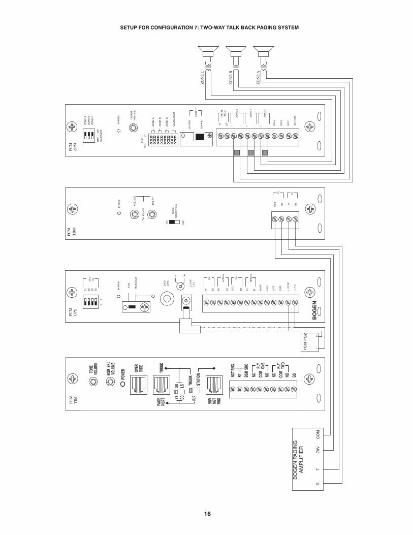
SETUP FOR CONFIGURATION 7: TWO-WAY TALK BACK PAGING SYSTEM

17
CONFIGURATION 7:TWO-WAY TALK BACK PAGING SYSTEM
This configuration is essentially the same as the one-way paging system described previously. The main difference between the one-way configuration and this configuration is that the centralized high-power amplifier is connected to the PCMTBM module instead of thePCMCPU module. The required setup includes: PCMTIM - PCMCPU - PCMTBM - PCMZPM - PCMPS2. Modules must be assembled,from left to right, in this order.
Notes: Talk Back is only available in High-Power Zones with 25 & 70V AC speakers. The paging access output from thetelephone system must support two-way communications.
INSTALLATION:
STEP 1: Assemble Modules PCMTIM to PCMCPU and to PCMZPM (see Illustration/Instructions on Appendix page 37,then return to this page and complete the following Steps).
Note: DO NOT connect the PCMPS2 (power supply) at this point.
STEP 2: Connecting Telephone System Paging Output to the PCMTIM
• Refer to paging access modes described previously in Step 2 on page 5 (paging port/contact closure), page 7 (paging port/VOX),page 9 (loop start trunk), page 11 (ground start trunk), or page 13 (station level/Centrex).
STEP 3: Switch Settings
• Set the two slide switches on the PCMTIM to match the paging output setting from the telephone system based on the type of in-terface used. See the first bullet within STEP 3 on page 5 if using Page Port Contact Closure; page 7 for Page Port VOX; page 9for Loop Start Trunk; page 11 for Ground Start Trunk; or page 13 for Station Level/Centrex.
• Set the SYS-ID DIP switches on the PCMCPU to the OFF position (to the left).• Set the RUN-PROGRAM switch on the PCMCPU to the RUN mode (up).• Set the TALK BACK switches for the zones requiring two-way talk back to the ON position (right) on the PCMZPM module.• Set the OUTPUT switch on the PCMZPM module to the HI-PWR position (down).
STEP 4: Testing your System
• Connect power supply PCMPS2 to the PCMCPU module to either the power jack 12V DC input or wire it to the 12V DCscrew terminals observing polarity.
• At this point all the power LEDs should be lit on each module.• Access the paging from the phone system and verify access tones (double beep) in handset.• Speak into the handset and listen. You should be able to hear the Talk Back Relay clicking back and forth inside the PCMTBM
module. (You must be near the PCM unit to hear it.)• At this point, the system should be functioning properly.• Disconnect Power Supply.
STEP 5: Connecting the Paging Amplifier
• Locate the terminals on the PCMTBM module labeled PA OUT/RT and wire to the COMMON and either 25 or 70V output on theBogen paging amplifier (either TPU-Series, GS-Series or Classic Series).
• Locate the terminals on the PCMTBM module labeled PA IN/RT and wire to the TIP and RING input on the Bogen paging amplifier.
STEP 6: Connecting 25 & 70V AC Speakers
• Locate the terminals on the PCMZPM module labeled ZONE A. These terminals have two connections marked + and - .Wire your speakers for ZONE ONE to these terminals. Observe polarity (-) to common (+) to selected tap setting.
• Follow the same procedure for the terminals labeled ZONE B for ZONE TWO, and the terminals labeled ZONE Cfor ZONE THREE.
STEP 7: Testing your System
• Connect the power supply PCMPS2 to the PCMCPU module to either the power jack 12V DC input or wire it to the 12V DCscrew terminals observing polarity.
• Connect the Bogen amplifier to the AC power outlet (120V AC 60Hz).• Set the volume on your Bogen amplifier to a 1/2 turn.• Access the paging from the telephone system and listen (on the handset) for the confirmation tone (double beep).• Dial 01 to access ZONE ONE and listen (on the handset and also to the speakers) for a pre-announce tone (single beep).
At this point you should be able to hear audio from the location where the speaker for ZONE ONE is installed.• The volume and delay controls on the PCMTBM module control the audio back into the handset. Adjust these controls
for best operation.• Set the Bogen amplifier to the desired volume level.

18
POW
ER
- 1.
5 A
OU
T
RT
GN
D
AU
X
GN
D
S1
S2
S3
S4
0
1
SYS
ID
RU
N
PRO
GR
AM
DA
TAL
INK
12 V
DC
1.5
A
-
IN RT
RTIN RTIN EM
/SC
+ 1
2VD
C
BO
GE
N
PA
LPB
GM
PA
HPB
GM+
POW
ER
RD
CO
M
+ - RD
A
RD
B
ZO
NE
AZ
ON
E B
ZO
NE
C
OF
F
O
NTA
LKB
AC
K
RTIN RD
C
LO
CA
LB
GM
ZO
NE
A
+ -Z
ON
E B
+ -Z
ON
E C
LPB
GM
VO
LU
ME
LO
PW
R
HI
PWR
OU
TPU
T
BG
MO
UT
I
N
PCM
ZPM
PCM
CPU
70V
CO
MT
RBO
GE
N P
AG
ING
AM
PLI
FIE
R
POW
ER
RD
CO
M
+ - RD
A
RD
B
ZO
NE
AZ
ON
E B
ZO
NE
C
OF
F
O
NTA
LKB
AC
K
RT
IN RD
C
LO
CA
LB
GM
ZO
NE
A
+ -Z
ON
E B
+ -Z
ON
E C
LPB
GM
VO
LU
ME
LO
PW
R
HI
PWR
BG
MO
UT
I
N
POW
ER
RD
CO
M
+ - RD
A
RD
B
ZO
NE
AZ
ON
E B
ZO
NE
C
OF
F
O
NTA
LKB
AC
K
RTIN RD
C
LO
CA
LB
GM
ZO
NE
A
+ -Z
ON
E B
+ -Z
ON
E C
LPB
GM
VO
LU
ME
LO
PW
R
HI
PWR
OU
TPU
T
BG
MO
UT
I
N
PCM
ZPM
POW
ER
- 1.
5 m
A
OU
T
RT
GN
D
AU
X
GN
D
S1
S2
S3
S4
0
1
SYS
ID
RU
N
PRO
GR
AM
DA
TAL
INK
12 V
DC
1.5
A
-
IN RT
RTIN RTIN EM
/SC
+ 1
2VD
C
BO
GE
N
PA
LPB
GM
PA
HPB
GM+
PCM
CPU
POW
ER
RD
CO
M
+ - RD
A
RD
B
ZO
NE
AZ
ON
E B
ZO
NE
C
OF
F
O
NTA
LKB
AC
K
RT
IN RD
C
LO
CA
LB
GM
ZO
NE
A
+ -Z
ON
E B
+ -Z
ON
E C
LPB
GM
VO
LU
ME
LO
PW
R
HI
PWR
OU
TPU
T
BG
MO
UT
I
N
PCM
ZPM
SA
TE
LL
ITE
AS
SE
MB
LY #
1
MA
ST
ER
AS
SE
MB
LY
PCM
ZPM
PCM
TB
M
POW
ER
VO
LU
ME
TAL
KB
AC
K
DE
LA
Y
OU
T
RT IN RT
PA PA
NO
ISE
RE
DU
CT
ION
ON
OFF
ZO
NE
A
ZO
NE
B
ZO
NE
C
GLO
BL
BG
M
ZO
NE
A
ZO
NE
B
ZO
NE
C
GLO
BL
BG
M
ZO
NE
A
ZO
NE
B
ZO
NE
C
GLO
BL
BG
M
ZO
NE
A
ZO
NE
B
ZO
NE
C
GLO
BL
BG
M
OU
TPU
T
PCM
TIM
SETUP FOR CONFIGURATION 8: TWO-WAY TALK BACK EXTENDED PAGING SYSTEM

19
CONFIGURATION 8:TWO-WAY TALK BACK EXTENDED PAGING SYSTEM
This configuration is essentially the same as the two-way paging system described previously on page 17. The main difference is theaddition of a satellite assembly.
The required setup includes: PCMTIM - 2 PCMCPU - PCMTBM - 4 PCMZPM - 2 PCMPS2
Note: Talk Back is only available in High-Power Zones with 25 & 70V AC speakers.
The paging access output from the telephone system must support two-way communications.
INSTALLATION:
STEP 1: Assemble Modules PCMTIM to PCMCPU and to PCMZPM (see Illustration/Instructions on Appendix page 37,then return to this page and complete the following Steps).
Note: DO NOT connect the PCMPS2 (power supply) at this point.
STEP 2: Assembling Satellite Modules PCMCPU to PCMZPM (see Illustration on page 18)
• Plug the 6-pin power connector from the PCMZPM module to the PCMCPU module jack (J2.) Be sure that the locking ridgefaces the header wall. (Green wire to the top).
• Plug the 26-pin ribbon cable from the PCMZPM module to the PCMCPU module 26-pin connector (J1). Be sure to align thepolarizing tab in slot. (Pin 1 red stripe to the top).
• The satellite systems are usually installed below the the master assembly and must be within 3 feet of each other.• Use an RCA cable to connect the PCMCPU modules from DATA LINK to DATA LINK RCA connectors. (See drawing on page 18)
STEP 3: Switch Settings
• Set the two slide switches on the PCMTIM to match the paging output setting from the telephone system based on the type ofinterface used. See the first bullet within STEP 3 on page 5 if using Page Port Contact Closure; page 7 for Page Port VOX;page 9 for Loop Start Trunk; page 11 for Ground Start Trunk; or page 13 for Station Level/Centrex. Then return to this page.
• Set the SYS-ID DIP switches on the master PCMCPU module to the OFF position (to the left).• Set the SYS-ID DIP switches on the first satellite PCMCPU module to the following configuration: switch 1 to the ON position
(to the right), switches 2, 3, & 4 to the OFF position (to the left). See additional SYS-ID settings on page 36.• Set the RUN-PROGRAM switch on each PCMCPU to the RUN mode (up).• Set the TALK BACK switches on the PCMZPM modules to the ON position (to the right) for all zones.• Set the OUTPUT switch on each PCMZPM module to the HI-PWR position (down).
STEP 4: Testing your System
• Connect one PCMPS2 power supply to each PCMCPU module to either the power jack 12V DC input or wire it to the 12V DCscrew terminals, observing polarity.
• At this point all the power LEDs should be lit on each module.• Access the paging from the phone system and verify access tones (double beep).• At this point, the system should be functioning properly.• Disconnect Power Supply.
STEP 5: Connecting the Paging Amplifier
• Locate the terminals on the PCMTBM module labeled PA OUT/RT and wire to the COMMON and either 25 or 70V output on theBogen paging amplifier (either TPU-Series, GS-Series or Classic Series).
• Locate the terminals on the PCMTBM module labeled PA IN/RT and wire to the TIP and RING input on the Bogen paging amplifier.
STEP 6: Connecting 25 & 70V AC Speakers
• Locate the terminals on the PCMZPM module labeled ZONE A. These terminals have two connections marked + and - .Wire your speakers for ZONE ONE to these terminals. Observe polarity (-) to common (+) to selected tap setting.
• Follow the same procedure for the terminals labeled ZONE B for ZONE TWO, and the terminals labeled ZONE Cfor ZONE THREE.
STEP 7: Testing your System
• Connect a PCMPS2 power supply to each PCMCPU module to either the power jack 12V DC input or wire it to the 12V DC screwterminals observing polarity.
• Connect the Bogen amplifier to the AC power outlet (120V AC 60Hz).• Set the volume on your Bogen amplifier to a 1/2 turn.• Access the paging from the telephone system and listen (on the handset) for the confirmation tone (double beep).• Dial 01 to access ZONE ONE and listen (on the handset and also to the speakers) for a pre-announce tone (single beep). At this
point, you should be able to hear audio from the location where the speaker for ZONE ONE is installed.• The volume and delay controls on the PCMTBM module, control the audio back into the handset. Adjust these controls for best op-
eration.• Set the Bogen amplifier to the desired volume level.

20
SETUP FOR CONFIGURATION 9: 3-ZONE / ONE-WAY PAGING / LOW-POWER SYSTEM / SELF-AMPLIFIED SPEAKERS

21
CONFIGURATION 9:3-ZONE / ONE-WAY PAGING / LOW-POWER SYSTEM / SELF-AMPLIFIED SPEAKERS
Low-Power System is a switch-selectable feature that allows the system designer to use self-amplified speakers on the zone outputs.The PCMZPM module that is to be used as a low-power module will switch only low-level signals to the zone outputs for use withdedicated amplifiers or self-amplified speakers. Note that its output switch is set to LO PWR.
Note: Low-Power Systems do not support two-way paging.
INSTALLATION:
STEP 1: Assemble Modules PCMTIM to PCMCPU and to PCMZPM (see Illustration/Instructions on Appendix page 37,then return to this page and complete the following Steps).
Note: DO NOT connect the PCMPS2 (power supply) at this point.
STEP 2: Connecting Telephone System Paging Output to the PCMTIM
• Refer to paging access modes described previously in Step 2 on page 5 (paging port/contact closure), page 7 (paging port/VOX),page 9 (loop start trunk), page 11 (ground start trunk), or page 13 (station level/Centrex). Then return to this page to completethe following Steps.
STEP 3: Switch Settings
• Set the two slide switches on the PCMTIM to match the paging output setting from the telephone system based on the typeof interface used. See the first bullet within STEP 3 on page 5 if using Page Port Contact Closure; page 7 for Page Port VOX;page 9 for Loop Start Trunk; page 11 for Ground Start Trunk; or page 13 for Station Level/Centrex. Then return to this page tocomplete the following Steps.
• Set the SYS-ID switches on the PCMCPU to the OFF position (to the left).• Set the TALKBACK switches on the PCMZPM to the OFF position (to the left) for all zones.• Set the LO PWR / HI PWR OUTPUT switch on the PCMZPM to the LO PWR position (up).
STEP 4: Connecting Self-Amplified Speakers
• Connect the [+] [-] for Zone A to the Audio Input on the Self-Amplified Speakers.
• Repeat this step for both Zone B and Zone C.
STEP 5: Testing your System
• Connect the power supply PCMPS2 to the PCMCPU module to either the power jack 12V DC input or wire it tothe 12V DC screw terminals, observing polarity.
• Access the paging from the telephone system and listen (on the handset) for the confirmation tone (double beep).• Dial 01 to access ZONE ONE and listen (on the handset and also to the speakers) for a pre-announce tone (single beep)
followed by your page (audio).• Follow the same steps for ZONES TWO (02) and THREE (03). Dial [00] for All-Page.
22
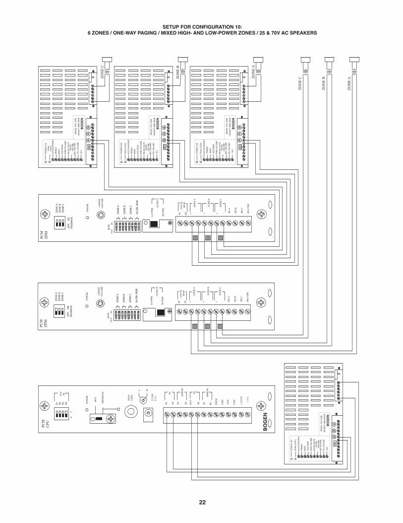
SETUP FOR CONFIGURATION 10:6 ZONES / ONE-WAY PAGING / MIXED HIGH- AND LOW-POWER ZONES / 25 & 70V AC SPEAKERS

23
CONFIGURATION 10:6 ZONES / ONE-WAY PAGING / MIXED HIGH- AND LOW-POWER ZONES / 25 & 70V AC SPEAKERS
High- and Low-Power Mixed System is a non-programmable feature that lets the system designer use a dedicated amplifier or self-am-plified speaker per zone and at the same time use a centralized amplifier for zones requiring less than 250 watts of power*. ThePCMZPM module to be used as a low-power module must have all three zones with dedicated amplifiers or self-amplified speakers andhave its output switch set to Low-Power. The other PCMZPM module will be used as a high-power module and its output switch mustbe set to High-Power. In this example, three dedicated amplifiers are used on the second PCMZPM low-power module.
Note: Low-Power Systems do not support two-way paging.
INSTALLATION:
STEP 1: Assemble Modules PCMTIM to PCMCPU and to PCMZPM (see Illustration/Instructions on Appendix page 37,then return to this page and complete the following Steps).
Note: DO NOT connect the PCMPS2 (power supply) at this point.
STEP 2: Connecting Telephone System Paging Output to the PCMTIM
• Refer to paging access modes described previously in Step 2 on page 5 (paging port/contact closure), page 7 (paging port/VOX),page 9 (loop start trunk), page 11 (ground start trunk), or page 13 (station level/Centrex). Then return to this page to completethe following Steps.
STEP 3: Switch and Control Settings
• Set the two slide switches on the PCMTIM to match the paging output setting from the telephone system based on the typeof interface used. See the first bullet within STEP 3 on page 5 if using Page Port Contact Closure; page 7 for Page Port VOX;page 9 for Loop Start Trunk; page 11 for Ground Start Trunk; or page 13 for Station Level/Centrex. Then return to this page tocomplete the following Steps.
• Set the SYS ID switches on the PCMCPU module to the OFF position (to the left).• Set the TALK BACK switches on the PCMZPM module to the OFF position (to the left) for all zones.• Set the LO PWR / HI PWR OUTPUT switch on the first PCMZPM High-Power module to the HI PWR OUTPUT position (down).• Set the LO PWR / HI PWR OUTPUT switch on the second PCMZPM Low-Power module to the LO PWR OUTPUT position (up).
STEP 4: Connecting Amplifiers
• Locate the terminals on the PCMCPU module labeled PA IN/RT and wire it to the TIP and RING (T & R) input on the amplifier.• Locate the terminals on the PCMCPU module labeled PA OUT/RT and wire it to the COMMON and either 25 or 70V AC output on
the amplifier.• Locate the terminals on the second PCMZPM module Low-Power module labeled ZONE A and connect the amplifier to the TIP and
RING terminals. Follow the same procedure for ZONE B and ZONE C.
STEP 5: Connecting 25 & 70V AC Speakers
• Locate the terminals on the PCMZPM module labeled ZONE A. These terminals have two connections marked + and - .Wire your speakers for ZONE ONE to these terminals. Observe polarity (-) to common (+) to selected tap setting.
• Follow the same procedure for the terminals labeled ZONE B for ZONE TWO, and the terminals labeled ZONE Cfor ZONE THREE.
STEP 6: Testing Your System
• Connect the power supply PCMPS2 to the PCMCPU module to either the power jack 12V DC input or wire it to the 12V DC screwterminals observing polarity.
• Connect the Bogen amplifiers to the AC power outlet (120 V AC 60Hz).• Set the volume on your Bogen amplifiers to a 1/2 turn.• Access the Paging from the telephone system and listen (on the handset) for the confirmation tone (double beep).• Dial 01 to access ZONE ONE and listen (on the handset and also to the speakers) for a pre-announce tone (single beep) followed
by your page (audio).• Follow the same steps for ZONES TWO (02) through SIX (06).• Set the Bogen amplifiers to the desired volume level.
* Older PCM systems only have a 150W capacity.

24
G
BK
R
Y
BL W
AU
DIO
OU
TP
UT
MIC
INP
UT
BO
GE
N
PR
S40
C
RE
LAY
VAR
1+ - 70
V
25V
600
CO
M
EM
ER
GE
NC
YM
ICR
OP
HO
NE
MIC
LIN
E
Con
tact
clo
sure
Dry
aud
io in
put t
o P
CM
TIM
(fr
om V
AR
1)
Not
use
d
Not
use
d
Dry
aud
io in
put t
o P
CM
TIM
(fr
om V
AR
1)
Con
tact
clo
sure
6 C
ON
DU
CTO
RM
OD
ULA
R C
AB
LE
RJ
11M
OD
ULA
R B
OX
MIC
VO
L
VO
X
SE
NS
DE
LAY
PCM
TIM
SETUP FOR CONFIGURATION 11: MICROPHONE OVERRIDE

25
CONFIGURATION 11:MICROPHONE OVERRIDE
Microphone Override is a feature that lets the system designer take priority over all paging functions and make a system-wide pageto all speakers.
In addition to the PCM modules, setup requires a Bogen VAR1 (voice-activated relay), PRS40C (12V DC power supply) and anMBS1000A or DDU250 (desktop microphone).
The Override feature includes a quad beep pre-announce tone which can be enabled or inhibited.
INSTALLATION:
STEP 1: Assemble Modules PCMTIM to PCMCPU and to PCMZPM (see Illustration/Instructions on Appendix page 37,then return to this page and complete the following Steps).
Note: DO NOT connect the PCMPS2 (power supply) at this point.
STEP 2: Connecting the Paging Amplifier
• Locate the terminals on the PCMCPU module labeled PA IN/RT and wire to the TIP and Ring (T & R) input on the Bogenpaging amplifier (either TPU-Series, GS-Series, or Classic Series amplifiers).
• Locate the terminals on the PCMCPU module labeled PA OUT/RT and wire to COMMON and either the 25 or 70V outputon the paging amplifier.
STEP 3: Connecting Optional Equipment
• Attach a 6-pin RJ11 modular jack to the wall next to the PCM2000 unit.• Connect the first audio output terminal from the top of the VAR1 (right screw terminals) to the RJ11 modular jack terminal
Y (yellow). Connect the second audio output terminal from the top of the VAR1 to the N.O. contact of the VAR1. See wiring diagramon page 24.
• Connect the fifth screw terminal from the top of the VAR1 (see drawing) to the RJ11 modular jack terminal BK (black).• Connect the relay terminals (normally open contacts) from the VAR1 (two bottom right screw terminals) to the RJ11 modular jack
terminals W (white) and BL (blue).• Connect the MBS1000A or DDU250 microphone leads to the VAR1 (left screw terminals).
1. Connections to the MB1000A: Red to the third screw, Black to the fifth screw, and Shield to the fourth screw.2. Connections to the DDU250: Red to the third screw, White to the fifth screw, and Shield to the fourth screw.
• Do not use the white and green wires from the MBS1000A or the blue and black wires from the DDU250 unless you want to usethem instead of the normally open contacts on the VAR1.
• Connect a 6-pin RJ11 modular cable between the RJ11 modular jack (previously attached to the wall next to the PCM2000)and the Override RJ11 input on the PCMTIM module.
• Connect the PRS40C power supply to the VAR1 (two top left screw terminals) observing polarity or use the mini-plug and connectit into the mini-jack at the bottom.
STEP 4: Switch and Control Settings
• Set the two slide switches on the PCMTIM to match the paging output setting from the telephone system based on the typeof interface used. See the first bullet within STEP 3 on page 5 if using Page Port Contact Closure; page 7 for Page Port VOX;page 9 for Loop Start Trunk; page 11 for Ground Start Trunk; or page 13 for Station Level/Centrex. Then return to this page tocomplete the following Steps.
• Set the Line/MIC switch on the VAR1 to the MIC position.• Set the Mic volume control on the VAR1 at 50%.
STEP 5: Testing Your System
• Connect the power supply PCMPS2 to the PCMCPU module to either the power jack 12V DC input or wire it to the 12V DC screwterminals observing polarity.
• Connect the Bogen amplifier to the AC power outlet (120V AC 60Hz).• Set the volume on your Bogen amplifier a half turn.• Access the paging from the telephone system and listen (on the handset) for the confirmation tone (double beep).• Dial 01 to access ZONE ONE and listen (on the handset and also to the speakers) for a pre-announce tone (single beep) followed
by your page (audio).• Follow the same steps for ZONES TWO (02) and THREE (03).• Access the emergency override by pressing the talk bar on the MBS1000A or sliding the DDU250 switch.• You should hear a quad beep pre-announce tone followed by your all-call/emergency page.• Adjust the VAR1 and PCM2000 controls for optimal operation.
NOTE: You will not be able to access individual zones using the Override feature, it is for All-Call Emergency only to all zones.

26
G
BK
R
Y
BL W
Not
use
dP
lay
stat
us c
onta
ct c
omm
on
Aud
io o
utpu
t (-)
Aud
io o
utpu
t (+
)
Pla
y st
atus
con
tact
Not
use
d
6 C
ON
DU
CTO
RM
OD
ULA
RC
AB
LE
RJ
11M
OD
ULA
RB
OX
G
BK
R
Y BL
W
PB
X
AN
ALO
G L
INE
Not
e S
witc
h se
tting
s: O
ff -
Up,
On
- D
own
24V
DC
PO
WE
RS
UP
PLY
PCM
TIM
11s
6
1sM
AXM
AXTI
ME
TIM
EM
INM
INTI
ME
TIM
E10
010
0
1 01VOX ENABLEVOX DIS
CONF TN PRE ANN TN
TRUNK MODESTATIONLOOP STARTGND START
DETECT CPCIGNORE
0TO
NE
TONE
M
USIC
M
USIC
VO
XVO
XDE
LAY
DELA
YST
ATIO
N/
TRU
NK
PAG
EO
UT
ON
PTPR
G/S
NO
CT
R
24VD
C15
0mA
CO
NTA
CT
CLO
SUR
ES NC
1-RNG DLY
NO TIMERTRNK TMER
ANS IMMED R
AN
GE
(SEC
)
INH
IBIT
11
100
- 200
01
50 -
100
01
1 - 5
00
0
PAGI
NGPA
GING
TIM
ETI
ME
< < < <
TAM
B2
TELE
PHO
NE
PAG
ING
AC
CES
S M
OD
ULE
O N12
34
56
78
9 DFT
120
SETUP FOR CONFIGURATION 12: DFT120 & TAMB2 WIRING DIAGRAM - GROUND START TRUNK OR STATION LEVEL

27
CONFIGURATION 12:DFT120 & TAMB2 WIRING DIAGRAM / GROUND START TRUNK OR STATION LEVEL
In this configuration, the telephone output is connected to the Bogen Telephone Access Module model TAMB2; the TAMB2 module isconnected to the Bogen Digital Feedback Terminator model DFT120; and the DFT120 is connected to the PCM2000 system. TheTAMB2 module is activated by the telephone system and, at the same time, the DFT120 is activated by the TAMB2ʼs normally opencontacts. Using digital technology, the DFT120 stores the DTMF tones and the paging audio. When the TAMB2 closed contacts areremoved from the DFT120, the DFT120 activates the PCM2000 system also using normally open contacts, and plays the page (audio).In addition to the above equipment, you will also need a 24V DC power supply and two RJ11 modular boxes.
INSTALLATION:
STEP 1: Assemble Modules PCMTIM to PCMCPU and to PCMZPM (see Illustration/Instructions on Appendix page 37,then return to this page and complete the following Steps).
Note: DO NOT connect the PCMPS2 (power supply) at this point.
STEP 2: Connecting the Paging Amplifier
• Locate the terminals on the PCMCPU module labeled PA IN/RT and wire to the TIP and Ring (T & R) input on the Bogenpaging amplifier (either TPU-Series, GS-Series, or Classic Series amplifiers).
• Locate the terminals on the PCMCPU module labeled PA OUT/RT and wire to COMMON and either the 25 or 70V outputon the paging amplifier.
STEP 3: Connecting an Analog Line or Ground Start Trunk from the Telephone System to the TAMB2
• Take the Analog Line or Ground Start trunk pair from the telephone system and wire it to the TAMB2 terminals T & R.
STEP 4: Connecting the TAMB2 Module to the DFT120
• Using a 6-pin RJ11 modular jack, connect terminals labeled PT & PR from the TAMB2 to the modular jack terminals R (red) and G(green).
• Connect terminals labeled N.O. & COM from the TAMB2 to the modular jack terminals Y (yellow) and BK (black).• Connect a 6-pin RJ11 modular cable from the RJ11 jack to the PAGE IN jacks on the DFT120. Place the switch labeled DL/LS to
the DL (Dry Loop) position.• Connect terminals labeled +24 & -24 from the TAMB2 to the 24V DC power supply. Bogen recommends using model PRS2403
(24V DC/300mA) or equivalent. • Connect the DFT120 power supply (supplied with the unit) to the DFT120.
STEP 5: Connecting the DFT120 to the PCMTIM Module
• Attach a 6-pin RJ11 modular jack to the wall next to the PCM2000 unit.• Connect terminals 3 & 4 from the DFT120 jack labeled AUDIO OUT, to the RJ11 modular jack terminals R (red) and G (green).• Connect terminals 2 & 5 from the DFT120 jack labeled AUDIO OUT (PLAY contact) to the RJ11 modular jack terminals Y (yellow)
and BK (black).• Connect a 6-pin RJ11 modular cable between the RJ11 modular jack and the TRUNK/ P/P RJ11 input on the PCMTIM module.
STEP 6: Switch and Control Settings
• Set DIP switches 1 and 3 on the TAMB2 to the ON position for Station access (see TAMB2 manual for complete instructions).• On the PCMTIM set the one slide-switch to CC (Contact Closure) and the other slide-switch to P/P (Page Port).
STEP 7: Testing Your System
• Connect the power supply PCMPS2 to the PCMCPU module to either the power jack 12V DC input or wire it to the 12V DC screwterminals observing polarity.
• Connect the power supplies and the amplifier to the AC power outlet 120V AC 60Hz.• Set the volume on your Bogen amplifier to a half turn.• Adjust the DFT120 AUDIO OUT volume control to 50%. (You may need to readjust this control higher or lower later, after the test.)• Access the paging from the telephone system. The RECORD LED on the DFT120 must be lit showing that the DFT120 is already
recording.• Dial 01 to record ZONE ONE DTMF tone followed by a test page. (Notice that you will not hear audio coming from the speakers at
this point.)• Hang-up the handset. The PLAY LED on the DFT120 must light showing that the DFT120 is playing the page and you must be able
to hear the page.• If the page is too low, adjust the control for optimal operation.

28
Con
tact
clo
sure
Dry
aud
io in
put t
o P
CM
TIM
(fr
om P
roH
old)
Not
use
d
Not
use
d
Dry
aud
io in
put t
o P
CM
TIM
(fr
om P
roH
old)
Con
tact
clo
sure
6 C
ON
DU
CTO
RM
OD
ULA
RC
AB
LEN
OR
MA
LLY
OP
EN
CU
STO
ME
RS
UP
PLI
ED
SW
ITC
H
PCM
TIM
LEVE
L
TNG
1S
T1 T2 T3 T4 COM
VM
IX
SETUP FOR CONFIGURATION 13: EMERGENCY ALERT TONES

29
CONFIGURATION 13:EMERGENCY ALERT TONES
Emergency Alert Tones is a non-programmable feature that lets the caller take priority over all paging functions and send an emergencyalert tone to all speakers. In addition to the PCM2000 modules, this option requires a Bogen VMIX (8-channel mixer/pre-amplifier),an input/output module RIO1S, and a Tone Generator module TNG1S.
INSTALLATION:
STEP 1: Assemble Modules PCMTIM to PCMCPU and to PCMZPM (see Illustration/Instructions on Appendix page 37,then return to this page and complete the following Steps).
Note: DO NOT connect the PCMPS2 (power supply) at this point.
STEP 2: Connecting the Paging Amplifier
• Locate the terminals on the PCMCPU module labeled PA IN/RT and wire to the TIP and Ring (T & R) input on the Bogenpaging amplifier (either TPU-Series, GS-Series, or Classic Series amplifiers).
• Locate the terminals on the PCMCPU module labeled PA OUT/RT and wire to COMMON and either the 25 or 70V outputon the paging amplifier.
STEP 3: Connecting Optional Equipment
• Insert a RIO1S module into Slot 7 or 8 of the VMIX, and insert the TNG1S into one of the other slots (1 thru 6).• Connect a 6-conductor cable between RJ11 modular jack on the RIO1S and the OVER RIDE input on the PCMTIM.• Any selected tone on the tone generator module TNG1S can be activated using a dry contact closure (relay, switch, etc.).
STEP 4: Switch and Control Settings
• Refer to paging access modules described previously. See instructions described in the first bullet within STEP 3 on page 5 if usingPage Port Contact Closure; page 7 for Page Port VOX; page 9 for Loop Start Trunk; page 11 for Ground Start Trunk; or page 13 forStation Level/Centrex. Then return to this page to complete the following Step.
STEP 5: Testing Your System
• Connect the power supply PCMPS2 to the PCMCPU module to either the power jack 12V DC input or wire it to the 12V DC screwterminals, observing polarity.
• Connect the Bogen amplifier to the AC power outlet (120V AC 60Hz).• Set the volume on your Bogen amplifier to a half turn.• Press the normally open customer supplied switch once and listen for the emergency tones.

30
CONFIGURATION 14:SINGLE AMPLIFIER BACKGROUND MUSIC LINE-LEVEL SIGNAL
Single amplifier BGM operation is a programmable feature that lets the PCM2000 use the paging amplifier to provide high-power BGMto the 25/70V AC speakers when the paging system is idle.
INSTALLATION:
STEP 1: Connecting Telephone System Paging Output to the PCMTIM
• Refer to paging access modes described previously in STEP 2 on page 5 (Paging Port/Contact Closure); page 7 (Page Port/VOX); page 9 (Loop Start Trunk); page 11 (Ground Start Trunk); or page 13 (Station Level/Centrex). Then return to this page to completethe following Steps.
STEP 2: Connecting the BGM Source
• Connect the BGM source output to the PCMTIM module terminals labeled BGM SRC/RT.
STEP 3: PCMCPU Switch Settings
• Remove the switch lock on the PCMCPU module and place the PROGRAM/RUN switch to the PROGRAM position (down), thegreen LED will illuminate.
• Refer to Switch setting described previously in STEP 3 on page 5 (Paging Port/Contact Closure); page 7 (Page Port/VOX);page 9 (Loop Start Trunk); page 11 (Ground Start Trunk); or page 13 (Station Level/Centrex). Then return to this page tocomplete the following Steps.
STEP 4: Activating the Background Music
• Access the PCM2000 system (either use a single 2500-series line telephone or butt set or dial the paging access number from thetelephone system). You will hear 3 beep tones indicating access to the programming mode.
• Dial 019 follow by the ( # ) key. You will hear a short double beep if the programming was accepted and stored in the system.
STEP 5: Prepare System for Operation
• Hang up the programming phone and then place the PROGRAM/RUN switch in the RUN position. The green LED will go out.Replace the switch lock.
BOGEN
DIGITAL TUNER
Music Source
POWER
PCMTIM
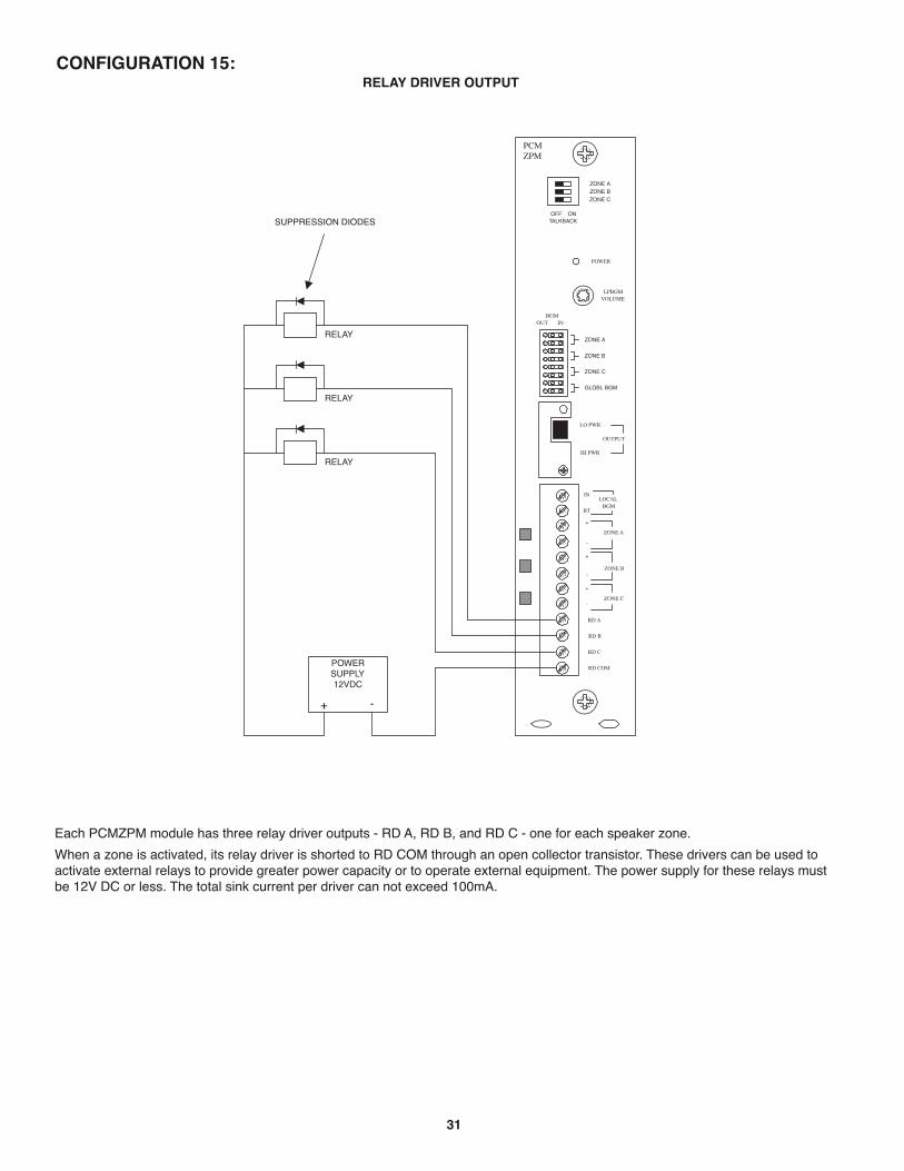
31
POWER
RD COM
+
-
RD A
RD B
ZONE AZONE BZONE C
OFF ONTALKBACK
RT
IN
RD C
LOCALBGM
ZONE A
+
-ZONE B
+
-ZONE C
LPBGMVOLUME
LO PWR
HI PWR
OUTPUT
BGMOUT IN
-+
SUPRESSION DIODES
POWERSUPPLY12VDC
RELAY
RELAY
RELAY
ZONE A
ZONE B
ZONE C
GLOBL BGM
CONFIGURATION 15:RELAY DRIVER OUTPUT
Each PCMZPM module has three relay driver outputs - RD A, RD B, and RD C - one for each speaker zone.
When a zone is activated, its relay driver is shorted to RD COM through an open collector transistor. These drivers can be used toactivate external relays to provide greater power capacity or to operate external equipment. The power supply for these relays mustbe 12V DC or less. The total sink current per driver can not exceed 100mA.
SUPPRESSION DIODES

32
SECTION II - PROGRAMMINGSYSTEM PROGRAMMING
System programming lets you set certain PCM options and tone features using the DTMF keys of a telephone. It also lets you programpaging zone groups and signaling zone groups.
All programming is accomplished through the TRUNK/P/P jack on the PCMTIM module regardless of the telephone interface used.
Note: To simplify initial programming, it is recommended that you use the Loop Start Trunk configuration with a single-line2500-series telephone or your Butt Set connected to the TRUNK/P/P input.
You do not need to program the system to set the zones. The system is ready from the factory to access individual zones andAll-Call.
To program the PCM2000 system, follow these instructions:
1. Remove the switch lock on the PCMCPU module and place the PROGRAM/RUN switch to the PROGRAM position (down).The green LED will illuminate.
2. Access the PCM2000 system (either use a single 2500-line telephone or butt set or dial the paging access number from thetelephone system).
3. You will hear 3 beep tones indicating access to the programming mode.
4. Dial the Feature Code for the option you wish to program. (See Feature Codes and Defaults list.)
Note: After you have entered a Feature Code (and any other data), you must press the [#] key to enter it into the system. If thesystem accepts the code (and data), you will hear a short double beep confirming that the data has been stored in the system.
Continue with the next Feature Code immediately after the confirming double beep.
If the information is not accepted, you will hear a busy tone. In this case, you should hang-up, check the code and the data, then re-ac-cess the system and try again.
5. Once you have finished programming, you must first hang-up the programming phone and then place the Program/Run switch in theRun position. The green LED will go out. Replace the switch lock.
Remember to press the [#] key after you enter a Feature Code.

33
FEATURE CODES AND DEFAULTS
Feature Feature Code Additional Data Default
Privacy Beep Inhibit 006 Enable 007 EnablePre-announce Tone Inhibit 003 Beep 004 Chime 005 ChimeConfirmation Tone Inhibit 001 Enable Enable 002 Emergency O/R Tone Inhibit 008 Inhibit Enable 009 All-Call Inhibit 010 Enable 011 EnableDialing Time-out Inhibit 012 Enable 013 EnableTrunk Disconnect Inhibit 014 Inhibit Enable 0151 Amp BGM Inhibit 018 Inhibit Enable 019 Default Timer 050 00-99 03 (See Note 1 - p. 35)VOX Timer 051 0-9 6 (See Note 2 - p. 35)Zone Group *01 Zones Numbers No Zones " " " *32 "EM/SC Zone Group *92 Zone Numbers All-Call No Tone 020 Follow Contact 021 2-Second Tone 022 3-Second Tone 023 3-Second Tone 4-Second Tone 024 5-Second Tone 025 6-Second Tone 026 7-Second Tone 027 Chime 028 Quad Beep 029Night Ring Zone Group *93 Zone Numbers All-Call No Tone 030 Simulated Ring 031 Ring Chime 032Code Call Zone Group *94 Zone Numbers All-Call Inhibit 040 Inhibit Pattern 041 Echo 042 1 Play 043 1 Play 1 Repeat 044 2 Repeat 045

34
Feature Feature Code Additional Data Default
Clock Set 060 HHMM 00:00Clock Sync. 067 HHMM (See Note 3 - p. 35) Inhibit 068 Inhibit Enable 069Time Trigger 1 Zone Group *81 Zone Numbers No Zones Inhibit 110 Inhibit Enable 111 HHMM (See Note 3 - p. 35) 2-Second Tone 112 3-Second Tone 113 3-Second Tone 4-Second Tone 114 5-Second Tone 115 6-Second Tone 116 7-Second Tone 117 8-Second Tone 118 Chime 119Time Trigger 2 Zone Group *82 Zone Numbers No Zones Inhibit 120 Inhibit Enable 121 HHMM (See Note 3 - p. 35) 2-Second Tone 122 3-Second Tone 123 3-Second Tone 4-Second Tone 124 5-Second Tone 125 6-Second Tone 126 7-Second Tone 127 8-Second Tone 128 Chime 129Time Trigger 3 Zone Group *83 Zone Numbers No Zones Inhibit 130 Inhibit Enable 131 HHMM (See Note 3 - p. 35) 2-Second Tone 132 3-Second Tone 133 3-Second Tone 4-Second Tone 134 5-Second Tone 135 6-Second Tone 136 7-Second Tone 137 8-Second Tone 138 Chime 139Time Trigger 4 Zone Group *84 Zone Numbers No Zones Inhibit 140 Inhibit Enable 141 HHMM (See Note 3 - p. 35) 2-Second Tone 142 3-Second Tone 143 3-Second Tone 4-Second Tone 144 5-Second Tone 145 6-Second Tone 146 7-Second Tone 147 8-Second Tone 148Time Trigger 5 Zone Group *85 Zone Numbers No Zones Inhibit 150 Inhibit Enable 151 HHMM (See Note 3 - p. 35) 2-Second Tone 152 3-Second Tone 153 3-Second Tone 4-Second Tone 154 5-Second Tone 155 6-Second Tone 156 7-Second Tone 157 8-Second Tone 158 Chime 159

35
Feature Feature Code Additional Data Default
Time Trigger 6 Zone Group *86 Zone Numbers No Zones Inhibit 160 Inhibit Enable 161 HHMM (See Note 3 - below) 2-Second Tone 162 3-Second Tone 163 3-Second Tone 4-Second Tone 164 5-Second Tone 165 6-Second Tone 166 7-Second Tone 167 8-Second Tone 168 Chime 169Time Trigger 7 Zone Group *87 Zone Numbers No Zones Inhibit 170 Inhibit Enable 171 HHMM (See Note 3 - below) 2-Second Tone 172 3-Second Tone 173 3-Second Tone 4-Second Tone 174 5-Second Tone 175 6-Second Tone 176 7-Second Tone 177 8-Second Tone 178 Chime 179Time Trigger 8 Zone Group *88 Zone Numbers No Zones Inhibit 180 Inhibit Enable 181 HHMM (See Note 3 - below) 2-Second Tone 182 3-Second Tone 183 3-Second Tone 4-Second Tone 184 5-Second Tone 185 6-Second Tone 186 7-Second Tone 187 8-Second Tone 188 Chime 189Reset Default 999Setup Tone(in Program Mode Only) Turn On 000 Turn Off Hang Up
Notes to Feature Codes
Note 1- These 2 digits represent time in 10s of seconds, i.e., "01" = 10 seconds, "02" = 20 seconds, "03" = 30 seconds, etc. Entering"00" will inhibit timer operation
Note 2 - This single-digit indicates VOX delay time in seconds, i.e., "1" = 1 second, "2" = 2 seconds, etc. Entering "0" will inhibit VOXtimer operation.
Note 3 - Entering the Feature Code without additional time data will enable feature using previously programmed time data.

36
Zone #ʼs S1 S2 S3 S4
Master 1-9 0 0 0 0
Satellite
1 10-18 1 0 0 0
2 19-27 0 1 0 0
3 28-36 1 1 0 0
4 37-45 0 0 1 0
5 46-54 1 0 1 0
6 55-63 0 1 1 0
7 64-72 1 1 1 0
8 73-81 0 0 0 1
9 82-90 1 0 0 1
10 91-99 0 1 0 1
SYS-ID SWITCH SETTINGS CHART FOR ADDITIONAL SATELLITE SYSTEMS

......................
.......................
......................
....................
......................................
PCM
TIM
PCM
CPU
PCM
TBM
PCM
ZPM
37
APPENDIX
STEP 1: Assembling Modules PCMTIM to PCMCPU and to PCMZPM (see Illustration above)
• Plug the 6-pin power connector from the PCMCPU module to the PCMTIM module jack (J2). Be sure that the lockingridge faces header wall. (Green wire to the top.)
• Plug the 26-pin ribbon cable from the PCMCPU module to the PCMTIM module 26-pin connector (J1). Be sure to alignthe polarizing tab in slot. (Pin 1 red stripe to the top.)
• Place the modules together and dress the connector cables away from the sheet metal so they will not get pinched.• Push the two units together while aligning the locking tabs in the PCMTIM module to the locking slots in the PCMCPU
module. Slide the two units until the faces of both units are even.• Secure the two units together by tightening a screw into the screw clamp tab in the back of the PCMTIM.• Follow the same steps to add the PCMZPM module(s).
NOTE:
Modules must be assembled,left to right, in the order shownhere: TIM, CPU, TBM (if necessary)and ZPM.
LOCKINGTAB
LOCKINGTAB
LOCKINGSLOT
LOCKINGTAB
LOCKINGSLOT
ALIGN CONNECTORS
SO LOCKINGRIDGE FACES
HEADER WALL
ALIGNPOLARIZINGTAB IN SLOT
SCREWCLAMPTAB & SLOT
Align polarizing tab in slot
Align connectorsso locking ridgefaces header wall.
Ribbon Cable Connector6-pin Connector
Module Assembly
Completed Assembly

38
NOTES

39
NOTES

50 Spring Street, Ramsey, NJ 07446 U.S.A.Tel. 201-934-8500 • Fax 201-934-983
www.bogen.com