pavement design for roads, streets, walks, and … 3 vehicular traffic 3-1. effect on pavement...
TRANSCRIPT

Pavement Design for Roads,
Streets, Walks, and Open
Storage Areas
Course# CV801
©EZpdh.com All Rights Reserved

CHAPTER 1
INTRODUCTION
1-1. Purpose. (5) Modulus of rupture (flexural strength) for
This manual provides criteria for the design of pavements for roads, streets, walks, and open stor- age areas at U.S. Army and Air Force installations.
1-2. Scope.
This manual provides criteria for plain concrete, reinforced concrete, flexible pavements, and design for seasonal frost conditions. These criteria include subgrade and base requirements, thickness designs, and compaction requirements, criteria for stabilized layers, concrete pavement joint details, and overlays.
1-3. References.
Appendix A contains a list of references used in this manual.
1-4. Selection of Pavement Type.
Rigid pavements or composite pavements with a rigid overlay are required for the following areas.
a. Vehicle Maintenance Areas. b. Pavements for All Vehicles with Nonpneuma-
tic Tires. c. Open Storage Areas with Materials Having
Nonpneumatic Loadings in Excess of 200 psi. d. Covered Storage Areas. e. Organizational Vehicle Parking Areas. f. Pavements Supporting Tracked Vehicles. g. Vehicle Wash Racks. h. Vehicle Fueling Pads.
Except for architectural or special operational re- quirements, all other pavements will be designed based upon life-cycle cost analysis.
1-5. Basis of Design.
a. Design Variables. The prime factor influenc- ing the structural design of a pavement is the load- carrying capacity required. The thickness of pavement necessary to provide the desired load- carrying capacity is a function of the following five principal variables-
(1) Vehicle wheel load or axle load. (2) Configuration of vehicle wheels or tracks. (3) Volume of traffic during the design life of
pavement. (4) Soil strength.
concrete pavements. b. Rigid Pavements. The rigid pavement design
procedure presented herein is based upon the criti- cal tensile stresses produced within the slab by the vehicle loading. Correlation between theory, small- scale model studies, and full-scale accelerated traf- fic tests have shown that maximum tensile stresses in the pavement occur when the vehicle wheels are tangent to a free or unsupported edge of the pavement. Stresses for the condition of the vehicle wheels tangent to a longitudinal or trans-verse joint are less severe because of the use of load-transfer devices in these joints to transfer a portion of the load to the adjacent slab. Other stresses, because of their cyclic nature, will at times be additive to the vehicle load stresses and include restraint stresses resulting from thermal expansion and contraction of the pavement and warping stresses resulting from moisture and temperature gradients within the pavement. Provision for those stresses not induced by wheel loads is included in design factors developed empirically from full-scale accelerated traffic tests and from the observed performance of pavements under actual service conditions.
c. Flexible Pavement. The design procedure used by the Corps of Engineers and the Air Force to design flexible pavements is generally referred to as the California Bearing Ratio (CBR) design pro- cedure. This procedure requires that each layer be thick enough to distribute the stresses induced by traffic so that when they reach the underlying layer they will not overstress and produce excessive shear deformation in the underlying layer. Each layer must also be compacted adequately so that traffic does not produce an intolerable amount of added compaction. Use ASTM D 1557 compaction effort procedures to design against consolidation under traffic. 1-6. Computer Aided Design.
In addition to the design procedures presented herein, computer programs are available for deter- mining pavement thickness and compaction re- quirements for roads, streets, and open storage areas. These programs are contained on the floppy disk appendix E located in pocket to cover 3.
a. Development. Computer programs have been

developed to aid in the design of pavements for identical to the data required by the design manual, roads, streets, and open storage areas. The pro- and the results obtained from the pro- gram should grams were developed on an IBM PC-AT using be close to the results obtained from the design FORTRAN 77 as the development language with curves. Because the computer program recalculates Microsoft's FORTRAN Compiler (version 3.2) and data and approximates certain empirical data, there MS-DOS (version 3.1) as the operating system. may be some minor differences in results from the Normally, the programs will be furnished as a program and from the manual. If significant compiled program which can be executed from difference are obtained contact HQUSACE floppy diskettes or hard drives. Thus far all the (CEMP-ET). programs have been run on IBM PC-AT or IBM c. Program names. The flexible pavement road compatible microcomputers containing a minimum design program is FRD 904, and the rigid pave- of 512K RAM. ment design program is RRD 805. The numbers in
b. Use of programs. In development of the com- the name refer to the date of the program. The first puter programs, an effort was made to provide a digit is the year of the revision. The last two digits user friendly program requiring no external in- of the program name is the month of the re- vision. structions for use of the programs. Aside from in- Thus, the program FRD 904 is the flexible road structions for initiating execution, which is standard design program that was revised in April 1989. for any executable program, the user is lead Care should be taken that the latest version of the through the design procedure by a series of ques- computer programs is being used. If there is doubt tions and informational screens. The input data re- concerning a program, contact HQUSACE quired for pavement design by the program are (CEMP-ET).

CHAPTER 2
PRELIMINARY INVESTIGATIONS
2-1. General. conditions in ditches, and cuts and tests of
The subgrade provides a foundation for supporting the pavement structure. As a result, the required pavement thickness and the performance obtained from the pavement during its design life will depend largely upon the strength and uniformity of the subgrade. Therefore, insofar as is economically feasible, a thorough investigation of the sub-grade should be made so that the design and construction will ensure uniformity of support for the pavement structure and realization of the maximum strength potential for the particular sub-grade soil type. The importance of uniformity of soil and moisture conditions under the pavement cannot be overemphasized with respect to frost action.
2-2. Investigations of Site.
Characteristics of subgrade soils and peculiar fea- tures of the site must be known to predict pave- ment performance. Investigations should determine the general suitability of the subgrade soils based on classification of the soil, moisture-density relation, degree to which the soil can be compact- ed, expansion characteristics, susceptibility to pumping, and susceptibility to detrimental frost action. Such factors as groundwater, surface infil- tration, soil capillarity, topography, rainfall, and drainage conditions also will affect the future sup- port rendered by the subgrade by increasing its moisture content and thereby reducing its strength. Past performance of existing pavements over a minimum of 5 years on similar local sub- rades should be used to confirm the proposed design criteria. All soils should be classified ac- cording to the Unified Soil Classification Systems (USCS) in ASTM D 2487.
2-3. Soil Conditions.
a. General survey of subgrade conditions. Sources of data should include the landforms, soil
representative soils in the site. The survey should be augmented with existing soil and geological maps. Both natural and subsurface drainage of the sub- grade must be considered.
b. Preliminary subsurface explorations. Prelimi- nary subsurface explorations should be made at in- tervals selected to test each type of soil and topog- raphy identified in the general survey. Additional subsurface explorations should be made in those areas where the preliminary investigation indicates unusual or potentially troublesome subgrade conditions. In determining subgrade conditions, borings will be carried to the depth of frost pene- tration, but no less than 6 feet below the finished grade. In the design of some high fills, it may be necessary to consider settlement caused by the weight of the fill. The depth requirements stated above will usually result in the subsurface explora- tions reaching below the depth of maximum frost penetration. If this is not the case, they should be extended to the maximum depth of frost penetra- tion below the design grade as determined from chapter 10.
c. Soil. Soil samples from the preliminary bor- ings should be classified and the data used to pre- pare soil profiles and to select representative soils for further testing. Measurements should include moisture contents which indicate soft layers in the soil. 2-4. Borrow Areas.
Where material is to be borrowed from adjacent areas, subsurface explorations should be made in these areas and carried 2 to 4 feet below the an- ticipated depth of borrow. Samples from the explo- rations should be classified and tested for moisture content and compactions characteristics.

CHAPTER 3
VEHICULAR TRAFFIC
3-1. Effect on Pavement Design. weights and the maximum allowable weights. For
Pavement thickness must be designed to withstand the anticipated traffic, categorized by type and weight of vehicles, and measured by average daily volume (ADV) of each type for the design life of the pavement. For most pavements, the magnitude of the axle load is of greater importance than the gross weight of pneumatic-tired vehicles because axle spacings are generally so large that there is little interaction between the wheel loads of one axle and the wheel loads of the other axles. Thus, for the case of pneumatic-tired vehicles having equal axle loads, the increased severity of loading imposed by conventional four- or five-axle trucks as compared with that imposed by two- or three- axle trucks is largely a fatigue effect resulting from an increased number of load repetitions per vehicle operation. For forklift trucks where the loading is concentrated largely on a single axle and for tracked vehicles where the loading is evenly divided between the two tracks, the severity of the vehicle loading is a function of the gross weight of the vehicle and the frequency of loading. Relations between load repetition and required rigid pavement thickness developed from accelerated traffic tests of full-scale pavements have shown that, for any given vehicle, increasing the gross weight by as little as 10 percent can be equivalent to increasing the volume of traffic by as much as 300 to 400 percent. On this basis, the magnitude of the vehicle loading must be considered as a more significant factor in the design of pavements than the number of load repetitions.
3-2. Traffic Evaluation.
Procedures for the evaluation of traffic and selec- tion of design index are as follows.
a. Pneumatic-tired vehicles. To aid in evaluating vehicular traffic for the purpose of pavement design, pneumatic-tired vehicles have been divided into the following three groups —
Group 1. Passenger cars, panel trucks, and pickup trucks
Group 2. Two-axle trucks Group 3. Three-, four-, and five-axle trucks
The design weights for various pneumatic-tired ve- hicles have been based on average weights, as de- termined from Federal Highway Administration traffic surveys made on public highways, plus one- fourth of the difference between these average
group 2 and group 3 vehicles, maximum allowable weights are based on single-axle and tandem-axle loadings not exceeding 18,000 and 32,000 pounds, respectively. Since traffic rarely will be composed of vehicles from a single group, pneumatic-tired vehicular traffic has been classified into five general categories based on the distribution of vehicles from each of the three groups listed above. These traffic categories are defined as follows —
Category I. Traffic composed primarily of pas- senger cars, panel and pickup trucks (group 1 vehicles), but containing not more than 1 percent two-axle trucks (group 2 vehicles).
Category II. Traffic composed primarily of pas- senger cars, panel and pickup trucks (group 1 vehicles), but may contain as much as 10 percent two-axle trucks (group 2 vehicles). No trucks having three or more axles (group 3 vehicles) are permitted in this category.
Category III. Traffic containing as much as 15 percent trucks, but with not more than 1 percent of the total traffic composed of trucks having three or more axles (group 3 vehicles).
Category IV. Traffic containing as much as 25 percent trucks, but with not more than 10 percent of the total traffic composed of trucks having three or more axles group 3 vehicles).
Category IVA. Traffic containing more than 25 percent trucks.
b. Tracked vehicles and forklift trucks. Tracked vehicles having gross weights not exceeding 15,000 pounds and forklift trucks having gross weights not exceeding 6,000 pounds may be treated as two- axle trucks (group 2 vehicles) and substituted for trucks of this type in the traffic categories defined above on a one-for-one basis. Tracked vehicles having gross weights exceeding 15,000 pounds but not 40,000 pounds and forklift trucks having gross weights exceeding 6,000 pounds but not 10,000 pounds may be treated as group 3 vehicles and substituted for trucks having three or more axles in the appropriate traffic categories on a on-for-one basis. Traffic composed of tracked vehicles ex- ceeding 40,000 pounds gross weight and forklift trucks exceeding 10,000 pounds gross weight has been divided into the following three categories —

increase in numerical value indicative of an increase in pavement design requirements. Table 3-1 gives the appropriate design index for combinations of the eight traffic categories based on distribution of traffic, vehicle type, and the six-letter classifications based on the volume of traffic. For example, suppose an average daily traffic (ADT) of 2,000 vehicles composed primarily of passenger cars, panel trucks, and pickup trucks (group 1), but including 100 two-axle trucks (group 2) is
c. Selection of design index. The design of anticipated for a road in flat terrain. First, the road pavements for Army and Air Force roads, streets, class is determined from TM 5-822-2/AFM 88-7, and similar areas is based on a “design index,” Chap. 5 to be a class D road. Second, the group 2 which represents the combined effect of the loads vehicles are 100/2,000 or 5 percent of the total of defined by the traffic categories just described and groups 1 and 2, making this category II traffic. the traffic volumes associated with each of the Therefore, the appropriate design index from table lettered classifications of roads or streets. This 3-1 is 2. index extends from one through ten with an
(1) Tracked vehicles and forklift trucks. tired vehicles, forklifts, and tracked vehicles are to
Provision is made whereby the designer may be considered, the proper letter classification of the determine pavement design requirements for road or street is determined from TM 5-822-2/ tracked vehicles or forklifts in combination with AFM 88-7, Chapter 5 according to the total volume traffic by pneumatic-tired vehicles or for traffic by of traffic from all types of vehicles. In table 3-1 the tracked vehicles or forklifts only. Where pneumatic- traffic for categories V, VI, and VII has been

divided further into various levels of frequency. If should be determined from the column for class E the tracked vehicle or forklift traffic is composed of roads or streets, again taking into account the vehicles from more than a single traffic category, it relative traffic frequencies where there are vehicles will be necessary for the designer to determine the from more than a single traffic category. anticipated frequency of traffic in each category in (2) Special-Purpose Vehicles. Information re- order to determine the appropriate design index. garding pavement design requirements for special For example, 40 vehicles per day of category VI purpose vehicles producing loadings significantly traffic require a greater pavement design index than greater than those defined in this manual will be does one vehicle per day of category VII traffic. requested from Headquarters, US Army Corps of Thus, the designer cannot rely on maximum gross Engineers (CEMP-ET), or the appropriate Air weight alone to determine pavement design index Force Major Command. values. For vehicular parking areas, the design index

CHAPTER 4
FLEXIBLE PAVEMENT SUBGRADES
4-1. Factors To Be Considered. 4-2. Compaction.
The information obtained from the explorations and The natural density of the subgrade must be suffi- tests previously described should be adequate to cient to resist densification under traffic or the enable full consideration of all factors affecting the subgrade must be compacted during construction suitability of the subgrade and subsoil. The primary to a depth where the natural density will resist factors are as follows: densification under traffic. Table 4-1 shows the
a. The general characteristics of the subgrade depth, measured from the pavement surface, at soils such as soil classification, limits, etc. which a given percent compaction is required to
b. Depth to bed rock. prevent densification under traffic. Subgrades in c. Depth to water table (including perched water cuts must have natural densities equal to or greater
table). than the values shown in table 4-1. Where such is d. The compaction that can be attained in the not the case, the subgrade must be compacted from
subgrade and the adequacy of the existing density the surface to meet the tabulated densities, or be in the layers below the zone of compaction require- removed and replaced in which case the ments. requirements for fills apply, or be covered with
e. The CBR that the compacted subgrade and sufficient select material, subbase, and base so that uncompacted subgrade will have under local envi- the uncompacted subgrade is at a depth where the ronmental conditions. in-place densities are satisfactory. In fill areas,
f. The presence of weak of soft layers in the cohesionless soils will be placed at no less than 95 sub- soil. percent of ASTM D 1557 maximum density nor
g. Susceptibility to detrimental frost action. cohesive fills at less than 90 percent 0 ASTM D 1557 maximum density.
4-3. Compaction Example. 12 inches below the pavement surface. Below this
An example illustrating the application of sub-grade compaction requirements is as follows:
a. Cohesion less subgrade. Assume a cleancohesionless sand and a design CBR of 18, with a natural in-place density of 90 percent of maximum density to beyond the depth of exploration of 6 feet. From table 4-1 for a design index of 5, it is found that 100 percent density must extend to a depth of
depth, fill sections must be compacted to 95 percent maximum density throughout, and cut sections to 95 percent of maximum density to a depth of 22 inches below the pavement surface. The designer must decide from previous experience or from test- section data whether or not these percentages of compaction in cut sections can be obtained from the top of the subgrade. If they cannot, a part of the subgrade must be removed, the underlying layer

compacted, and the material replaced, or the should be 85 percent of maximum density to thickness of select material or subbase must be so conform to fill requirements. increased that the densities in the uncompacted subgrade will be adequate. 4-4. Selection of Design CBR Values.
b. Cohesive subgrade. Assume a lean clay, adesign CBR of 7, and a natural in-place density of 83 percent of maximum density extending below the depth of exploration of 6 feet. Compaction of the subgrade from the surface would be impracticable with ordinary equipment beyond the 6- to 8-inch depth that could be processed; therefore, the minimum depth of cut would be limited by the in- place density. From table 4-1 for a design index of 5, it is found that the 83 percent in-place natural density would be satisfactory below depths of about 25 inches from the pavement surface. From CBR design curves (explained subsequently), the top of the subgrade will be 14.5 inches below the pavement surface; therefore, a zone 10.5 inches thick below the top of the subgrade requires treat- ment. The bottom 6 to 8 inches of this can be proc- essed in place; so about 4 inches of material must be removed and replaced. Compaction to 95 percent of maximum density is required for all cohesive material that lies within 12 inches of the pavement surface. Since the subgrade does not fall within this zone compaction requirements in the replaced material should be 90 percent to conform to fill requirements, and the layer processed in place
Flexible pavements may be designed using the lab- oratory soaked CBR, the field in-place CBR, or the CBR from undisturbed samples as described in MIL-STD-621A, Method 101. For the design of flexible pavements in areas where no previous ex- perience regarding pavement performance is avail- able, the laboratory soaked CBR is normally used. Where an existing pavement is available at the site that has a subgrade constructed to the same standards as the job being designed, in-place tests or tests on undisturbed samples may be used in se- lecting the design CBR value. In-place tests are used when the subgrade material is at the maximum water content expected in the prototype. Contrarily, tests on undisturbed samples are used where the material is not at the maximum water content and thus soaking is required. Sampling involves considerably more work than in-place tests; also, "undisturbed" samples tend to be slightly disturbed; therefore, in-place tests should be used where possible. Guides for determining when in-place tests can be used are given in details of the CBR test in MIL-STD-621A, Test Method 101.

CHAPTER 5
FLEXIBLE PAVEMENT SELECT MATERIALS AND SUBBASE
COURSES
5-1. General.
It is common practice in pavement design to use locally available or other readily available materials between the subgrade and base course for econ- omy. These layers are designated in this manual as select materials or subbases. Those with design CBR values equal to or less than 20 are designated select materials, and those with CBR values above 20 are designated subbases. Minimum thicknesses of pavement and base have been established to eliminate the need for subbases with design CBR values above 50. Where the design CBR value of the subgrade without processing is in the range of 20 to 50, select materials and subbases may not be needed. However, the subgrade cannot be assigned design CBR values of 20 or higher unless it meets the gradation and plasticity requirements for sub- bases.
5-2. Materials.
The investigations described in chapter 2 will be used to determine the location and characteristics of suitable soils for select material and subbase construction.
a. Select materials. Select materials will normal- ly be locally available coarse-grained soils (prefix G or S), although fine-grained soils in the ML and CL groups may be used in certain cases. Limerock, coral, shell, ashes, cinders, caliche, disintegrated granite, and other such materials should be consid- ered when they are economical. Recommended plasticity requirements are listed in table 5-1. A maximum aggregate size of 3 inches is suggested to aid in meeting grading requirements.
b. Subbase materials. Subbase materials may in this way is not satisfactory. Material stabilized consist of naturally occurring coarse-grained soils with commercial additives may be economical as a or blended and processed soils. Materials such as subbase. Portland cement, lime, flyash, or bitumen limerock, coral, shell, ashes, cinders, caliche, and and combinations thereof are commonly employed disintegrated granite may be used as subbases when for this purpose. Also, it may be possible to they meet the requirements described in table 54. decrease the plasticity of some materials by use of The existing subgrade may meet the requirements lime or portland cement in sufficient amounts to for a subbase course or it may be possible to treat make them suitable as subbases. the existing subgrade to produce a subbase. However, admixing native or processed materials 5-3. Compaction. will be done only when the unmixed subgrade meets the liquid limit and plasticity index requirements for subbases. It has been found that "cutting" plasticity
These materials can be processed and compacted with normal procedures. Compaction of subbases will be 100 percent of ASTM D 1557 density

except where it is known that a higher density can struction is available, CBR tests may be made in be obtained practically, in which case the higher place on material when it has attained its maximum density should be required. Compaction of select expected water content or on undisturbed soaked materials will be as shown in table 4-1 except that samples. The procedures for selecting CBR design in no case will cohesionless fill be placed at less values described for subgrades apply to select than 95 percent or cohesive fill at less than 90 materials and subbases. CBR tests on gravelly percent. materials in the laboratory tend to give CBR values
higher than those obtained in the field. The 5-4. Drainage. difference is attributed to the processing necessary
Subbase drainage is an important aspect of design and should be accomplished in accordance with TM 5-820-2/AFM 88-5, Chap. 2.
5-5. Selection of Design CBR Values.
The select material or subbase will generally be uniform, and the problem of selecting a limiting condition, as described for the subgrade, does not ordinarily exist. Tests are usually made on remolded samples; however, where existing similar con-
to test the sample in the 6-inch mold, and to the confining effect of the mold. Therefore, the CBR test is supplemented by gradation and Atterberg limits requirements for subbases, as shown in table 5-1. Suggested limits for select materials are also indicated. In addition to these requirements, the material must also show in the laboratory tests a CBR equal to or higher than the CBR assigned to the material for design purposes.

CHAPTER 6
FLEXIBLE PAVEMENT BASE COURSES
6-1. Materials. High-quality materials must be mold, the laboratory CBR test will not be used in used in base courses of flexible pavements. These determining CBR values of base courses. In-stead, high-quality materials provide resistance to the high selected CBR ratings will be assigned as shown in stresses that occur near the pavement surface. the following tabulation. These ratings have been Guide specifications for graded crushed aggregate, based on service behavior records and, where limerock, and stabilized aggregate may be used pertinent, on in-place tests made on materials that without qualification for design of roads, streets, had been subjected to traffic. It is imperative that and parking areas. Guide specifications for dry- and the materials conform to the quality requirements water-bound macadam base courses may be used given in the guide specifications so that they will for design of pavements only when the cost of the develop the needed strengths. dry- or water-bound macadam base does not exceed the cost of stabilized-aggregate base course, and the ability of probable bidders to construct pavements with dry- or water-bound macadam base to the required surface smoothness and grade tolerances has been proved by experience in the area.
6-2. Compaction. Base courses placed in flexible pavements should be compacted to the maximum density practicable, generally in excess of 100 percent of ASTM D 1557 maximum density but never less than 100 percent of ASTM D 1557 maximum density. 6-5. Minimum Thickness. The minimum allow-
able thickness of base course will be 4 inches as 6-3. Drainage. Drainage design for base courses shown in table 6-1, except that in no case will the should be accomplished in accordance with TM 5- total thickness of pavement plus base for class A 820-2/AFM 88-5, Chap. 2. through D roads and streets be less than 6 inches
nor less than frost design minimum specified in 6-4. Selection of Design CBR. Because of the chapter 18 when frost conditions are controlling. effects of processing samples for the laboratory TM 5-822-5/AFM 88-7, Chap. 1 CBR tests and because of the effects of the test
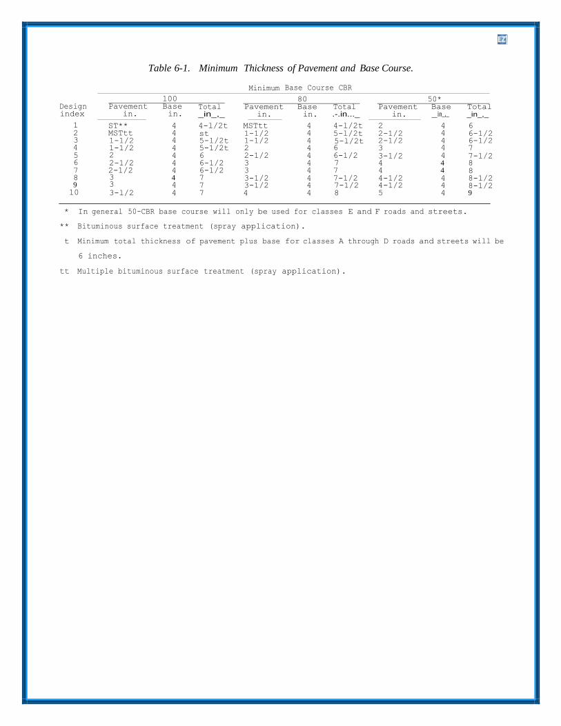
Table 6-1. Minimum Thickness of Pavement and Base Course.
Minimum Base Course CBR
100 80 50* Design Pavement Base Total Pavement Base Total Pavement Base Total index in. in. _in_,_ in. in. .-.in..._ in. in_,_ _in_,_
1 ST** 4 4-l/2t MSTtt 4 4-l/2t 2 4 6 2 MSTtt 4 st 1-1/2 4 5-l/2t 2-1/2 4 6-1/2 3 1-1/2 4 5-l/2t 1-1/2 4 5-l/2t 2-1/2 4 6-1/2 4 1-1/2 4 5-1/2t 2 4 6 3 4 7 5 2 4 6 2-1/2 4 6-1/2 3-1/2 4 7-1/2 6 2-1/2 4 6-1/2 3 4 7 4 4 8 7 2-1/2 4 6-1/2 3 4 7 4 4 8 8 3 4 7 3-1/2 4 7-1/2 4-1/2 4 8-1/2 9 3 4 7 3-1/2 4 7-1/2 4-1/2 4 8-1/2 10 3-l/2 4 7 4 4 8 5 4 9
* In general 50-CBR base course will only be used for classes E and F roads and streets.
** Bituminous surface treatment (spray application).
t Minimum total thickness of pavement plus base for classes A through D roads and streets will be
6 inches.
tt Multiple bituminous surface treatment (spray application).

CHAPTER 7
BITUMINOUS PAVEMENT
7-1. General. or tar) should normally be based on economy.
The bituminous materials used in paving are as- phaltic or tar products as listed in TM 5-822-8/ 7-2. Criteria for Bituminous Pavements.
AFM 88-6, Chap 9. Although asphalts and tars re- The basic criteria for selection and design of bitu- semble each other in general appearance, they do minous pavements are contained in TM 5-822-8 not have the same physical or chemical character- which includes the following criteria: istics. Tars are affected to a greater extent by tem- a. Selection of bitumen type.perature changes and whether conditions; however, b. Selection of bitumen grade.they tend to have better adhesive and penetrating c. Aggregate requirements.properties than asphalts. Generally asphalt surface d. Quality requirements.courses are preferred to tar surface courses. The e. Types of bituminous pavements.selection of the type of bituminous material (asphalt

CHAPTER 8
FLEXIBLE PAVEMENT DESIGN
8-1. General. instances, be modified rather than stabilized. In
Flexible pavement designs will provide the follow- ing:
a. Sufficient compaction of the subgrade and ofeach layer during construction to prevent objec- tionable settlement under traffic.
b. Adequate drainage of base course.c. Adequate thickness above the subgrade and
above each layer together with adequate quality of the select material, subbase, and base courses to prevent detrimental shear deformation under traffic and, when frost conditions are a factor, to control or reduce to acceptable limits effects of frost heave or permafrost degradation.
d. A stable, weather-resistant, wear-resistant wa- terproof, nonslippery pavement.
addition, when unbound granular layers are employed between two bound layers (e.g., an un- bound base course between an asphalt concrete (AC) surface course and a stabilized subbase course), it is imperative that adequate drainage be provided the unbound layer to prevent entrapment of excessive moisture in the layer. Additional in- formation on soil stabilization may be - obtained from TM 5-818-1.
c. All-bituminous concrete. All-bituminous con- crete pavements are also designed using equivalency factors (see para 8-6). The procedure is the same as for stabilized soil layers discussed above.
8-3. Design Index.
The design of flexible pavements for roads, streets, 8-2. Design Procedure. parking areas, open storage, and similar areas will
a. Conventional flexible pavements. In designingconventional flexible pavement structures, the design values assigned to the various layers are applied to the curves and criteria presented herein. Generally, several designs are possible for a specific site, and the most practical and economical design is selected. Since the decision on the practicability of a particular design may be largely a matter of judgment, full particulars regarding the selection of the final design (including cost estimates) will be included in the design analysis. For computer aided design, see paragraph 1-6.
b. Stabilized Soil Layers. Flexible pavementscontaining stabilized soil layers are designed through the use of equivalency factors. A conven-
be based on a design index, which is an index rep- resenting all traffic expected to use a flexible pavement during its life. It is based on typical magnitudes and compositions of traffic reduced to equivalents in terms of repetitions of an 18,000- pound, single-axle, dual-tire load. Selection of the design index will be accomplished as stated in chapter 3. The designer is cautioned that in select- ing the design index, consideration will be given to traffic which may use the pavement structure during various stages of construction and to other foreseeable exceptional use.
8-4. Thickness Criteria-Conventional Flexible Pavements.
tional flexible pavement is first designed and the Thickness design requirements are given in figure 8- equivalency factors applied to the thickness of the 1 in terms of CBR and design index. Minimum layer to be stabilized. When stabilized materials thickness requirements are shown in table 6-1. For meeting all gradation, durability, and strength re- frost condition design, thickness requirements will quirements indicated in TM 5-822-4, and in chap ter be determined from chapter 18 of this manual. In 17 herein are utilized in pavement structures, an regions where the annual precipitation is less than appropriate equivalency factor may be applied. Soils 15 inches and the water table (including perched which have been mixed with a stabilizing agent and water table) will be at least 15 feet below the which do not meet the requirements for a stabilized finished pavement surface, the danger of high soil are considered modified and are designed as moisture content in the subgrade is reduced. Where conventional pavement layers. When portland in-place tests on similar construction in these cement is used to stabilize base course materials in regions indicate that the water content of the Air Force Pavements, the treatment level must be subgrade will not increase above the optimum, the maintained below approximately 4 percent by total pavement thickness, as determined by CBR weight to minimize shrinkage cracking which will tests on soaked samples, may be reduced by as reflect through the bituminous concrete surface much as 20 percent. The minimum thickness of course. In this case, the base course will, in most pavement and base course must still be met; there-
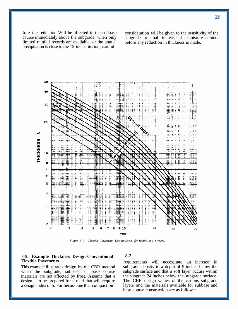
fore the reduction Will be affected in the subbase course immediately above the subgrade. when only limited rainfall records are available, or the annual precipitation is close to the 15-inch criterion, careful
consideration will be given to the sensitivity of the subgrade to small increases in moisture content before any reduction in thickness is made.
50
40
30
20
10
9
8
7
6
5
4
3
2
2 3 4 5 6 7 8 9 10
CBR
20 30 50
Figure 8-1. Flexible Pavement Design Curve for Roads and Streets.
8-5. Example Thickness Design-Conventional Flexible Pavements.
This example illustrates design by the CBR method when the subgrade, subbase, or base course materials are not affected by frost. Assume that a design is to be prepared for a road that will require a design index of 5. Further assume that compaction
8-2
requirements will necessitate an increase in subgrade density to a depth of 9 inches below the subgrade surface and that a soft layer occurs within the subgrade 24 inches below the subgrade surface. The CBR design values of the various subgrade layers and the materials available for subbase and base course construction are as follows:
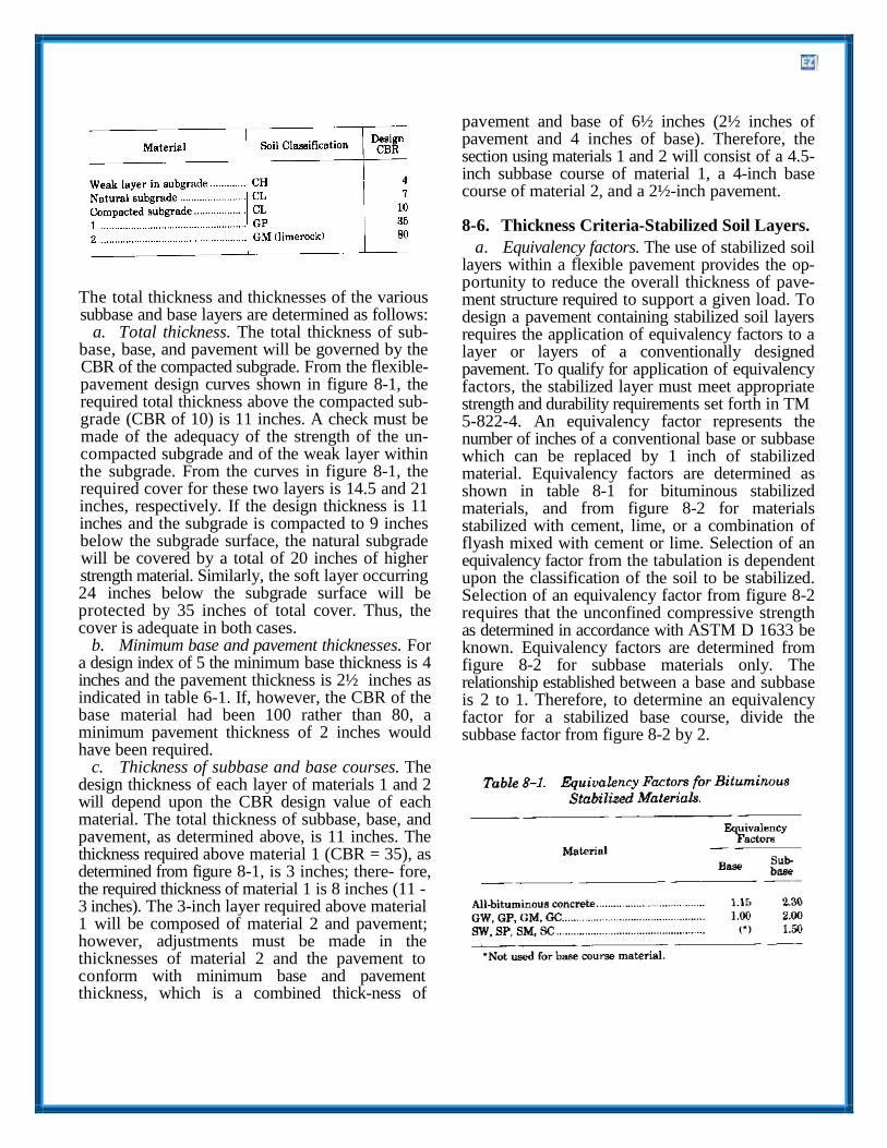
The total thickness and thicknesses of the various subbase and base layers are determined as follows:
a. Total thickness. The total thickness of sub- base, base, and pavement will be governed by the CBR of the compacted subgrade. From the flexible- pavement design curves shown in figure 8-1, the required total thickness above the compacted sub- grade (CBR of 10) is 11 inches. A check must be made of the adequacy of the strength of the un- compacted subgrade and of the weak layer within the subgrade. From the curves in figure 8-1, the required cover for these two layers is 14.5 and 21 inches, respectively. If the design thickness is 11 inches and the subgrade is compacted to 9 inches below the subgrade surface, the natural subgrade will be covered by a total of 20 inches of higher strength material. Similarly, the soft layer occurring 24 inches below the subgrade surface will be protected by 35 inches of total cover. Thus, the cover is adequate in both cases.
b. Minimum base and pavement thicknesses. Fora design index of 5 the minimum base thickness is 4 inches and the pavement thickness is 2½ inches as indicated in table 6-1. If, however, the CBR of the base material had been 100 rather than 80, a minimum pavement thickness of 2 inches would have been required.
c. Thickness of subbase and base courses. Thedesign thickness of each layer of materials 1 and 2 will depend upon the CBR design value of each material. The total thickness of subbase, base, and pavement, as determined above, is 11 inches. The thickness required above material 1 (CBR = 35), as determined from figure 8-1, is 3 inches; there- fore, the required thickness of material 1 is 8 inches (11 - 3 inches). The 3-inch layer required above material 1 will be composed of material 2 and pavement; however, adjustments must be made in the thicknesses of material 2 and the pavement to conform with minimum base and pavement thickness, which is a combined thick-ness of
pavement and base of 6½ inches (2½ inches of pavement and 4 inches of base). Therefore, the section using materials 1 and 2 will consist of a 4.5- inch subbase course of material 1, a 4-inch base course of material 2, and a 2½-inch pavement.
8-6. Thickness Criteria-Stabilized Soil Layers.
a. Equivalency factors. The use of stabilized soillayers within a flexible pavement provides the op- portunity to reduce the overall thickness of pave- ment structure required to support a given load. To design a pavement containing stabilized soil layers requires the application of equivalency factors to a layer or layers of a conventionally designed pavement. To qualify for application of equivalency factors, the stabilized layer must meet appropriate strength and durability requirements set forth in TM 5-822-4. An equivalency factor represents the number of inches of a conventional base or subbase which can be replaced by 1 inch of stabilized material. Equivalency factors are determined as shown in table 8-1 for bituminous stabilized materials, and from figure 8-2 for materials stabilized with cement, lime, or a combination of flyash mixed with cement or lime. Selection of an equivalency factor from the tabulation is dependent upon the classification of the soil to be stabilized. Selection of an equivalency factor from figure 8-2 requires that the unconfined compressive strength as determined in accordance with ASTM D 1633 be known. Equivalency factors are determined from figure 8-2 for subbase materials only. The relationship established between a base and subbase is 2 to 1. Therefore, to determine an equivalency factor for a stabilized base course, divide the subbase factor from figure 8-2 by 2.

Figure 8-2. Equivalency Factors for Soils Stabilized with Cement, Lime, or Cement and Lime Mixed with Flyash.
b. Minimum thickness. The minimum thicknessrequirements for a stabilized base or subbase is 4 inches. The minimum thickness requirements for the asphalt pavement are the same as shown for conventional pavements in table 6-1.
8-7. Example Thickness Design-Stabilized Soil Layers.
To use the equivalency factors requires that a con ventional flexible pavement be designed to support the design load conditions. If it is desired to use a

stabilized base or subbase course, the thickness of conventional base or subbase is divided by the equivalency factor for the applicable stabilized soil. Examples for the application of the equivalency factors are as follows—
a. Example 1. Assume a conventional flexiblepavement has been designed which requires a total thickness of 16 inches above the subgrade. The minimum thickness of AC and base is 2 and 4 inches, respectively, and the thickness of subbase is 10 inches. It is desired to replace the base and subbase with a cement-stabilized gravelly soil having an unconfined compressive strength of 890 psi. From figure 8-2 the equivalency factor for a subbase having an unconfined compressive strength of 890 is 2.0. Therefore, the thickness of stabilized subbase is 10 inches ÷2.0=5.0 inches. To calculate the thickness of stabilized base course, divide the subbase equivalency factor by 2 and then divide the unbound base course thickness by the result. Therefore, 4 inches ÷1.0 = 4.0 inches of stabilized base course. The final section would be 2 inches of AC and 9 inches of cement-stabilized gravelly soil. The base course thickness of 4.0 inches would also have been required due to the minimum thickness of stabilized base.
b. Example 2. Assume a conventional flexiblepavement has been designed which requires 2 inches of AC surface, 4 inches of crushed stone base, and 6 inches of subbase. It is desired to construct an all- bituminous pavement (ABC). The equivalency factor from table 8-1 for a base course is 1.15 and for a subbase is 2.30. The thickness of AC required to replace the base is 4 inches ÷1.15=3.5 inches, and the thickness of AC required to replace the subbase is 6 inches ÷2.30 = 2.6 inches. Therefore, the total thickness of the ABC pavement is 2+3.5+2.6 or 8.1 inches, which would be rounded to 8.0 inches.
8-8. Shoulders and Similar Areas.
These areas are provided only for the purpose of minimizing damage to vehicles which use them ac- cidentally or in emergencies; therefore, they are not considered normal vehicular traffic areas. Normally, only shoulders for class A roads will be paved. Others will be surfaced with soils selected for their stability in wet weather and will be compacted as required. Dust and erosion control will be provided by means of vegetative cover, anchored mulch, coarse-graded aggregate, or liquid palliatives (TM 5-830-3/AFM 88-17, Chap 3). Shoulders will not block base-course drainage, particularly where frost
conditions are a factor. Where paving of shoulders is deemed necessary, the shoulders will be designed as a class F road or street.
8-9. Bituminous Sidewalks.
Permanent bituminous sidewalks will consist of a 4- inch-thick base with a 1-inch-thick bituminous surfacing. Material used locally in base construction for roads will normally be suitable as sidewalk base material. Bases may also be constructed of soils stabilized or modified in place with portland cement, lime, bituminous materials, or other acceptable stabilizers. In frost and permafrost areas, bases of sidewalks should be nonfrost-susceptible. The bituminous surfacing may consist of hot- or cold-mix bituminous concrete, sand-asphalt or sand- tar mixes, or sheet asphalt; in locations where the surface texture is not of prime importance, bituminous surface treatments may be used. Temporary walks or walks that are seldom used will be constructed of stable or stabilized soils or rock screenings containing granular and colloidal materials combined in the proportions necessary to ensure maximum density and stability under varied weather conditions, including frost action. Where necessary, the life of these walks may be prolonged by the application of bituminous surface treatments or by the addition of suitable stabilizing agents. The use of soil sterilants may be considered to prevent vegetation growth through bituminous sidewalks.
8-10. Bituminous Driveways.
Base course materials in residence driveway areas will be compacted to not less than 100 percent, and the top 6 inches of the subgrade to not less than 90 percent (95 percent for cohesionless sands and gravels) of the maximum density from ASTM D 1557. Minimum base course thicknesses for resi- dence driveways are as follows:
The minimum paving requirements for residence driveways are a multiple bituminous surface treat- ment for base course CBR values less than 80 and a single-bituminous surface treatment for CBR values of 80 or above.

8-11. Curbs and Gutters. gutters will not block the drainage of base course
Curbs and gutters will be provided with a founda- tion at least 4 inches thick of material of 50-CBR minimum. The material will be nonfrost-susceptible
(TM 5-822-2/AFM 88-7, Chap 5).
8-12. Flexible Overlay Design.
when required and will be compacted to the same For the design of flexible pavement overlays, see requirements as the base or subbase course at the chapter 14 of this manual. same elevation. The foundation for curbs and

CHAPTER 9
RIGID PAVEMENT DESIGN
9-1. Soil Classification and Tests. All soils density from ASTM D 1557, no rolling is necessary should be classified according to the Unified Soil other than that required to pro- vide a smooth Classification System (USGS) as given in ASTM D surface. Compaction requirements for cohesive soils 2487. There have been instances in construction (LL > 25; PI > 5) will be 90 percent of maximum specifications where the use of such terms as density for the top 6 inches of cuts and the full "loam," “gumbo,” "mud," and "muck" have resulted depth of fills. Compaction requirements for in misunderstandings. These terms are not specific cohesionless soils (LL < 25: PI <5) will be 95 and are subject to different interpretations percent for the top 6 inches of cuts and the full throughout the United States. Such terms should depth of fills. Compaction of the top 6 inches of not be used. Sufficient investigations should be cuts may require the subgrade to be scarified and performed at the proposed site to facilitate the de- dried or moistened as necessary and recompacted to scription of all soils that will be used or removed the desired density. during construction in accordance with ASTM D c. Special soils. Although compaction increases2487; any additional descriptive information con- the stability and strength of most soils, some soil sidered pertinent should also be included. If Atter- types show a marked decrease in stability when berg limits are a required part of the description, as scarified, worked, and rolled. Also, expansive soils indicated by the classification tests, the test pro- shrink excessively during dry periods and expand cedures and limits should be referenced in the con- excessively when allowed to absorb moisture. When struction specifications. soils of these types are encountered, special
treatment will usually be required. For nominally 9-2. Compaction. expansive soils, water content, compaction effort,
a. General. Compaction improves the stability ofthe subgrade soils and provides a more uniform foundation for the pavement. ASTM D 1557 soil compaction test conducted at several moisture con- tents is used to determine the compaction charac- teristics of the subgrade soils. The range of maxi- mum densities normally obtained in the compaction test on various soil types is listed in TM 5-825-2. This test method should not be used if the soil contains particles that are easily broken under the blow of the tamper unless the field method of compaction will produce a similar degradation. Certain types of soil may require the use of a laboratory compaction control test other than the above-mentioned compaction test. The unit weight of some types of sands and gravels obtained using the compaction method above may be lower than the unit weight that can be obtained by field com- paction; hence, the method may not be applicable. In those cases where a higher laboratory density is desired, compaction tests are usually made under some variation of the ASTM D 1557 method, such as vibration or tamping (alone or in combination) with a type hammer or compaction effort different from that used in the test.
b. Requirements. For all subgrade soil types, thesubgrade under the pavement slab or base course must be compacted to a minimum depth of 6 inches. If the densities of the natural subgrade materials are equal to or greater than 90 percent of the maximum
and overburden should be determined to control swell. For highly expansive soils, replacement to depth of moisture equilibrium, raising grade, lime stabilization, prewetting, or other acceptable means of controlling swell should be considered (see TM 5-818-7 for guidance).
9-3. Treatment of Unsuitable Soils. Soils not suitable for subgrade use (as specified in TM 5-825- 2/AFM 88-6, Chap 2, and MIL-STD-619) should be removed and replaced or covered with soils which are suitable. The depth to which such adverse soils should be removed or covered depends on the soil type, drainage conditions, and depth of freezing temperature penetration and should be determined by the engineer on the basis of judgment and previous experience, with due consideration of the traffic to be served and the costs involved. Where freezing temperatures penetrate a frost-susceptible subgrade, design procedures outlined in chapter 17 herein, or TM 5-852-3 as applicable, should be followed. In some instances, unsuitable or adverse soils may be improved economically by stabilization with such materials as cement, flyash, lime, or certain chemical additives, whereby the characteristics of the composite material become suitable for subgrade purposes. Criteria for soil stabilization are in TM 5-822-4. However, subgrade stabilization should not be attempted unless the costs reflect corresponding savings in base-course,
9-1

pavement, or drainage facilities construction. vail at the proposed site. Table 9-1 presents typical values of k for various soil types and moisture
9-4. Determination of Modulus of Subgrade conditions. These values should be considered as a Reaction. For the design of rigid pavements in guide only, and their use in lieu of the field plate- those areas where no previous experience regarding bearing test, although not recommended, is left to pavement performance is available, the modulus of the discretion of the engineer. Where a base course subgrade reaction k to be used for design purposes is used under the pavement, the k value on top of is determined by the field plate-bearing test. This the base is used to determine the pavement test procedure and the method for evaluating its thickness. The plate-bearing test may be run on top results are given in MIL-STD-621A. Where per- of the base, or figure 9-1 may be used to determine formance data from existing rigid pavements are the modulus of soil reaction on top of the base. It is available, adequate values for k can usually be de- good practice to confirm adequacy of the k on top termined on the basis of consideration of soil type, of the base from figure 9-1 by running a field plate- drainage conditions, and frost conditions that pre- load test.
9-2

Figure 9-1. Effect of Base-Course Thickness on Modulus of Soil Reaction.
CHAPTER 10
RIGID PAVEMENT BASE COURSES
10-1. General Requirements.
Base courses may be required under rigid pave- ments for replacing soft, highly compressible or ex- pansive soils and for providing the following.
a. Additional structural strength.
b. More uniform bearing surface for the pave- ment.
c. Protection for the subgrade against detrimen- tal frost action.
d. Drainage.
e. Suitable surface for the operation of construc- tion equipment, especially slipform pavers.
Use of base courses under a rigid pavement to pro- vide structural benefit should be based on econ.-my of construction. The first cost is usually less for an increase in thickness than for providing a thick base course. However, thick base courses have often resulted in lower maintenance costs since the thick base course provides stronger foundation and therefore less slab movement. A minimum base- course thickness of 4 inches is required over subgrades that are classified as OH, CH, CL, MH, ML, and OL to provide protection against pumping. In certain cases of adverse moisture conditions (high water table or poor drainage), SM and SC soils also may require base courses to prevent pumping. The designer is cautioned against the use of fine-grained material for leveling courses or choking open-graded base courses since this may create a pumping condition. Positive drainage should be provided for all base courses to ensure water is not trapped directly beneath the pavement since saturation of these layers will cause the pumping condition that the base course is intended to prevent. The base course material and drains must meet the drainage criteria listed in TM 5-820- 2/AFM 88-5, Chap. 2.
10-2. Materials.
If conditions indicate that a base course is desirable under a rigid pavement, a thorough investigation should be made to determine the source, quantity, and characteristics of the available materials. A study should also be made to determine the most economical thickness of material for a base course that will meet the requirements. The base course may consist of natural, processed, or stabilized materials. The material selected should be the one that best accomplishes the intended purpose of the base course. In general, the base- course material should be a well-graded, high-stability material. In this connection all base courses to be placed beneath concrete pavements for military roads and streets should conform to the fol-lowing requirements:
a. Percent passing No.10 sieve; Not more than85.
b. Percent passing No.200 sieve: Not more than15.
c. Plasticity index: Not higher than 6.Where local experience indicates their desirability, other control limitations such as limited abrasion loss may be imposed to ensure a uniform high- quality base course.
10-3. Compaction.
Where base courses are used under rigid pavements, the base-course material should be compacted to a minimum of 95 percent of the maximum density. The engineer is cautioned that it is difficult to compact thin base courses to high densities when they are placed on yielding subgrades.
10-4. Frost Requirements.
In areas where subgrade soils are subjected to sea- sonal frost action detrimental to the performance of pavements, the requirements for base-course thickness and gradation will follow the criteria in chapter 18 of this manual.

CHAPTER 11
CONCRETE PAVEMENT
11-1. Mix Proportioning and Control. used for concrete with the maximum size aggregate
Proportioning of the concrete mix and control of the concrete for pavement construction will be in accordance with TM 5-822-7. Normally, a design flexural strength at 28-day age will be used for the pavement thickness determination. Should it be necessary to use the pavements at an earlier age, consideration should be given to the use of a design flexural strength at the earlier age or to the use of
up to 2 inches. When aggregate larger than the 2- inch nominal size is used in the concrete, the cross- sectional dimensions of the beam will be at least three times the nominal maximum size of the aggregate, and the length will be increased to at least 2 inches more than three times the depth.
11-3. Special Conditions.
high early strength cement, whichever is more Mix proportion or pavement thickness may have to economical. Flyash gains strength more slowly than be adjusted due to results of concrete tests. If the cement, so that if used it may be desirable to select tests show a strength gain less than predicted or a a strength value at a period other than 28 days if retrogression in strength, then the pavement would time permits. have to be thicker. If the concrete strength was
higher than predicted, then the thickness may be 11-2. Testing. reduced. Rather than modifying the thickness
The flexural strength of the concrete and lean con- crete base will be determined in accordance with ASTM C 78. The standard test specimen will be a 6- by 6-inch section long enough to permit testing over a span of 18 inches. The standard beam will be
required as a result of tests on the concrete, the mix proportioning could be changed to increase or decrease the concrete strength, thereby not chang- ing the thickness.

CHAPTER 12
PLAIN CONCRETE PAVEMENT DESIGN
12-1. General. tained from the design chart presented in figure 12-
Rigid pavements for roads, streets, and open stor- age areas at military installations will be plain (nonreinforced) concrete except for those condi- tions listed in chapter 13 or unless otherwise ap- proved by HQUSACE (CEMP-ET), or the appropriate Air Force Major Command.
12-2. Roller-Compacted Concrete Pavements.
Roller-compacted concrete pavements (RCCP) are plain concrete pavements constructed using a zero- slump portland cement concrete mixture that is placed with an AC paving machine and compacted with vibratory and rubber-tired rollers. The design of RCCP is presented in chapter 17.
12-3. Design Procedure.
For convenience in determining design require- ments, the entire range of vehicle loadings and traffic intensities anticipated during the design life of pavements for the various classifications of mili- tary roads and streets has been expressed as an equivalent number of repetitions of an 18,000- pound single-axle loading. To further simplify the design procedure, the range of equivalent repeti- tions of the basic loading thus determined has been designated by a numerical scale defined as the pavement design index. This index extends from 1 through 10 with an increase in numerical value indicative of an increase in pavement design requirements. Values for the design index are de- termined using the procedure in chapter 3. Once the design index has been determined the required thickness of plain concrete pavement is then ob-
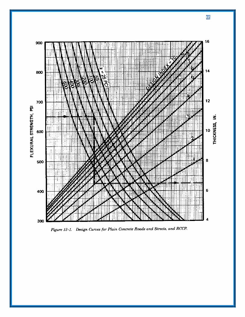
1 for roads and streets. Figure 12-2 is used to determine the thickness of parking and storage areas except that the thickness of roller-compacted concrete parking and storage areas will be designed using figure 12-1. These design charts are graphical representations of the interrelation of flexural strength, modulus of subgrade reaction k, pavement thickness, and repetitions (design index) of the basic 18,000-pound single-axle loading. These design charts are based on the theoretical analyses of Westergaard (New Formulas for Stresses in Concrete Pavements of Airfields, ASCE Transactions), supplemented by empirical modifi- cations determined from accelerated traffic tests and observations of pavement behavior under actual service conditions. The design charts are entered using the 28-day flexural strength of the concrete. A horizontal projection is then made to the right to the design value for k. A vertical projection is then made to the appropriate design-index line. A second horizontal projection to the right is then made to intersect the scale of pavement thickness. The dashed line shown on curves is an example of the correct use of the curves. When the thickness from the design curve indicates a fractional value, it will be rounded up to the next ½-inch thickness. All plain concrete pavements will be uniform in cross- sectional thickness. Thickened edges are not normally required since the design is for free edge stresses. The minimum thickness of plain concrete for any military road, street, or open storage area will be 6 inches.

12-4. Design Procedure for Stabilized Founda- ho = thickness of plain concrete pavement over- tions. lay required over the stabilized layer, inches
The thickness requirements for a plain concrete pavement on a modified soil foundation will be de- signed as if the layer is unbound using the k value measured on top of the modified soil layer. For sta- bilized soil layers, the treated layer will be consid- ered to be a low-strength base pavement and the thickness determined using the following modified partially bonded overlay pavement design equation:
where
hd = thickness of plain concrete pavement from design chart (fig. 12-1) based on k value of unbound material, inches
Ef = flexural modulus of elasticity of the stabi- lized soil. The modulus value for bituminous stabilized soils will be determined according to the procedures in appendix B. The modulus value for lime and cement stabilized soils will be determined using the results of CRD-C 21 and the equations in appendix B
hs = thickness of stabilized layer, inches
For additional information on stabilization and mix chapter 3, the 50-kilopounds (kip) tracked vehicles proportioning see TM 5-822-4 and TM 5-818-1. would be classified as category V traffic. For a fire-
quench of 50 of these vehicles per lane per day, the 12-5. Design Examples. pavement design index would be 6. The 80-kip
As an example of the application of the design pro- cedures given for nonstabilized foundations, design a plain concrete pavement for a road in a rural area on rolling terrain to carry the following traffic:
Based on the criteria in TM 5-822-2/AFM 88-7, Chap 5, this traffic would be evaluated as requiring a class C road. It would be designed for category IV traffic and a design index of 5. Assuming a 28- day flexural strength for the concrete of 675 psi, and a k value of 100 pounds per cubic inch (pci), the required pavement thickness as indicated by figure 12-1 is approximately 7.3 inches. This thick- ness value would be rounded off to 7.5 inches for design. To illustrate the design procedure when traffic includes tracked vehicles, assume that in addition to the pneumatic-tired traffic used in the previous example, the designer must provide for an average of 60 tanks per lane per day and that the gross weight of each tank is 50,000 pounds. The
tracked vehicles are classified as category VI traffic. For a frequency of 20 of these vehicles per lane per day, the pavement design index would be 7. Thus, it can be seen that the 80-kip tracked vehicle traffic governs as it requires the highest design index. Assuming the same 28-day flexural strength and k value as in the previous design examples, the required pavement thickness is 8.1 inches (fig 12-1) which would be rounded to 8.5 inches for design. For this same example, if the plain concrete pavement is to be placed on 6 inches of cement stabilized soil having an E~ value of 500,000 psi, then the thickness of plain concrete re- quire would be as follows using equation 12-1.
Design examples for rigid pavement for frost con- ditions are discussed in chapter 18.
12-6. Concrete Sidewalks.
50,000-pounds gross weight would be classified as Portland cement concrete walks may be provided at category V traffic (according to chapter 3) since it installations where pedestrian traffic justifies this exceeds the maximum of 40,000 pounds permitted type of construction. Normally, the design thickness for tracked vehicles in category IV traffic. Inasmuch for walks will be 4 inches. Where it is necessary and as the tank traffic exceeds 40 per day, the rigid desirable to continue the walk across driveways and pavement design index would be based on the next private entrances, provided for vehicle crossings, higher traffic volume given in table 3-1, which is the thickness of the walk should be increased to 100 per day. Thus, the design index for a class C provide sufficient strength to support the vehicular street would be 6. Assuming the same 28-day loads to which such portions of the walks will be flexural strength and k value as in the previous subjected. Concrete walks should be grooved example, the required pavement thickness is transversely into rectangular areas with the longest approximately 7.75 inches (fig 12-1) and would re- dimension no greater than 1.25 times the shorter quire a design thickness of 8.0 inches. To illustrate dimension to create planes of weakness for control the procedure for combining tracked vehicles with of contraction cracking. The depth of such grooves pneumatic-tired vehicles, design a rigid pavement should be a minimum of one-fourth the thickness of on rolling terrain for the following traffic: the slab and need not be sealed. Expansion joints
consisting of approved preformed bituminous filler or wood approximately ½ inch thick should be installed to surround or to separate all structures or features which project through or against the sidewalk slab. Expansion joints of a similar type should be installed at regularly spaced intervals transversely across the sidewalk slab. The spacing
According to TM 5-822-2/AFM 88-7, Chap 5, the for such joints should be not less than 30 feet nor traffic on rolling terrain would be evaluated as re- more than 50 feet. A base is only recommended at quiring a class D road or class E street. From locations where past experience has shown that sub-

grade soils exhibit unacceptable swell and frost 50 pci, and when frost penetrates a frost-susceptible heave potential. These soils can result in safety material underlying the rigid pavement on small jobs problems with differential joint elevations. in frost areas. Where the flexural strength or
subgrade modulus is unknown, the design will be 6 12-7. Concrete Driveways. inches of concrete with a 6-inch base course.
Under normal conditions, rigid pavement for resi- dential driveways will be either 6-inch plain con- crete or 5-inch reinforced concrete with 0.10 per- cent of reinforcement steel. In plain concrete pave- ment design, slab lengths will not exceed 15 feet with 12 feet recommended. For reinforced pave- ment, slab lengths up to 30 feet may be used. The residential driveways will be 6 inches thick and re- inforced with a minimum of 0.05 percent of rein-
Contraction or construction joints pro- vided in a driveway will be designed and sealed in accordance with chapter 15 or 16. Expansion joints consisting of approved preformed bituminous filler or wood should be installed to surround or separate all structures which project through or against the driveway slabs.
12-8. Curbs, Gutters, and Shoulders.
forcement steel when the following adverse condi- For a discussion of the design of curbs, gutters, and tions prevail: when concrete flexural strength is shoulders, see paragraphs 8-8 and 8-11 of this below 630 psi and the subgrade modulus k is below manual.

CHAPTER 13
REINFORCED CONCRETE PAVEMENTS
13-1. Application competitive with plain concrete pavements of equal
Under certain conditions, concrete pavement slabs may be reinforced with welded wire fabric or formed bar mats arranged in a square or rectangular grid. The advantages of using steel reinforcement include a reduction in the required slab thickness, greater spacing between joints, and reduced differential settlement due to nonuniform support or frost heave.
a. Subgrade conditions. Reinforcement mayreduce the damage resulting from cracked slabs. Cracking may occur in rigid pavements founded on subgrades where differential vertical movement is a definite potential. An example is a foundation with definite or borderline frost susceptibility that cannot feasibly be made to conform to conventional frost design requirements.
b. Economic considerations. In general, rein- forced concrete pavements will not be economically
load-carrying capacity, even though a reduction in pavement thickness is possible. Alternate bids, however, should be invited if reasonable doubt exists on this point.
c. Plain concrete pavements. In otherwise plainconcrete pavements, steel reinforcement should be used for the following conditions:
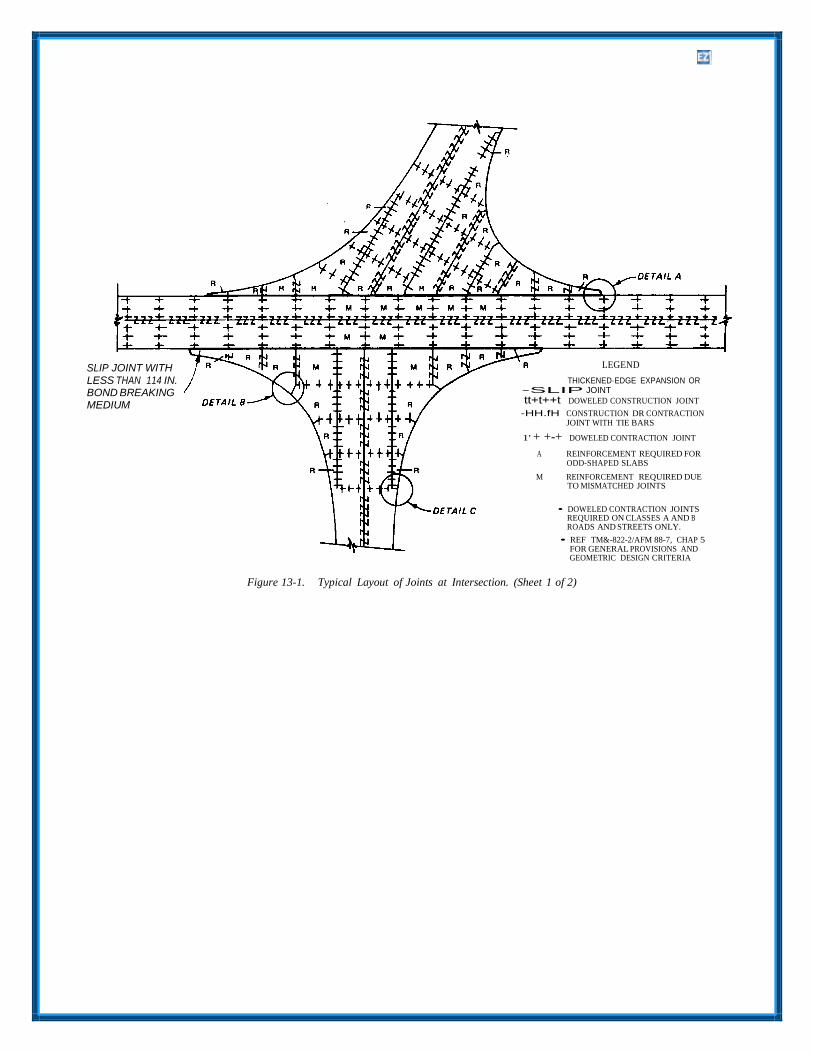
(1) Odd-shaped slabs. Odd-shaped slabs should be reinforced in two directions normal to each other using a minimum of 0.05 percent of steel in both directions. The entire area of the slab should be reinforced. An odd-shaped slab is considered to be one in which the longer dimension exceeds the shorter dimension by more than 25 percent or a slab which essentially is neither square nor rectangular. Figure 13-1 includes examples of reinforcement required in odd-shaped slabs.
SLIP JOINT WITH LESS THAN 114 IN. BOND BREAKING MEDIUM
LEGEND
THICKENED·EDGE EXPANSION OR -SLIP JOINT
tt+t++t DOWELED CONSTRUCTION JOINT
-HH.fH CONSTRUCTION DR CONTRACTION JOINT WITH TIE BARS
1' + +-+ DOWELED CONTRACTION JOINT
A REINFORCEMENT REQUIRED FOR ODD-SHAPED SLABS
M REINFORCEMENT REQUIRED DUE TO MISMATCHED JOINTS
• DOWELED CONTRACTION JOINTS REQUIRED ON CLASSES A AND B ROADS AND STREETS ONLY.
• REF TM&-822-2/AFM 88-7, CHAP 5 FOR GENERAL PROVISIONS ANDGEOMETRIC DESIGN CRITERIA
Figure 13-1. Typical Layout of Joints at Intersection. (Sheet 1 of 2)

(2) Mismatched joints. A partial traffic testing. Although some cracking will occur in reinforcement or slab is required where the joint the pavement under the design traffic loadings, the patterns of abutting pavements or adjacent paving steel rein-forcing will hold the cracks tightly closed. lanes do Dot match, unless the pavements are The reinforcing will prevent spalling or faulting at positively separated by an expansion joint or slip- the cracks and provide a serviceable pavement type joint having Dot less than ¼-inch bond- during the anticipated design life. Essentially, the breaking medium. The pavement slab directly design method consists of determining the opposite the mismatched joint should be reinforced percentage of steel required, the thickness of the with a minimum of 0.05 percent of steel in reinforced concrete pavement, and the minimum directions normal to each other for a distance of 3 allowable length of the slabs. Figure 13-2 presents feet back from the juncture and for the full width or a graphic solution for the design of reinforced length of the slab in 8 direction normal to the concrete pavements. Since the thickness of a mismatched joint. Mismatched joints normally will reinforced concrete pavement is a function of the occur at intersections of pavements or between percentage of steel reinforcing, the designer may pavement and fillet areas as shown in figure 13-1. determine either the required percentage of steel for
d. Other uses. Reinforced concrete pavements a predetermined thickness of pavement or the may be considered for reasons other than those de- required thickness of pavement for a predetermined scribed above provided that a report containing a percentage of steel. In either case, it is necessary justification of the need for reinforcement is pre- first to determine the required thickness of plain pared and submitted for approval to HQUSACE concrete pavement by the method outlined (CEMP-ET) or the appropriate Air Force Major previously in chapter 12. The plain concrete Command. pavement thickness hd (to the nearest 0.1 inch) is
used to enter the nomograph in figure 13-2. A 13-2. Design Procedure. straight line is then drawn from the value of hd to
a. Thickness design on unbound base or the value selected for either the reinforced concrete
subbase. The design procedure for reinforced pavement thickness hr or the percentage of
concrete pavements uses the principle of allowing a reduction in the required thickness of plain concrete pavement due to the presence of the steel reinforcing. The design procedure has been developed empirically from a limited Dumber of prototype test pavements subjected to accelerated
reinforcing steel S. It should be noted that the S value indicated by figure 13-2 is the percentage to be used in the longitudinal direction only. For normal designs, the percentage of steel used in the transverse direction will be one- half of that to be used in the longitudinal direction. In fillets, the percent steel will be the same in both directions.

Once the h,.and S values have been determined, the maximum allowable slab length Lis obtained from the intersection of the straight line and the scale or
L. Difficulties may be encountered in sealing joints between very long slabs because of large volumetric changes caused by temperature changes.
b. Thickness design on stabilized base orsubgrade. Ta determine the thickness requirements for reinforced concrete pavement on a stabilized foundation, it is first necessary to determine the thickness of plain concrete pavement required over
the stabilized layer using procedures set forth in chapter 12. This thickness of plain concrete is then used with figure 13-2 to design the reinforced concrete pavement in the same manner discussed above for nonstabilized foundations.
13-3. Limitations. prevent excessive separation during concrete
The design criteria for reinforced concrete pave- ment for military roads and streets are subject to the following limitations.
a. No reduction in the required thickness of plainconcrete pavement should be allowed for per- centages of longitudinal steel less than 0.05 percent.
b. No further reduction in the required thicknessof plain concrete pavement should be allowed over that indicated in figure 13-2 for 0.5 percent longitudinal steel, regardless of the percentage of steel used.
c. The maximum length L of reinforced concretepavement slabs should not exceed 75 feet regardless of the percentage of longitudinal steel, yield strength of the steel, or thickness of the pavement. When long slabs are used, special consideration must be given to joint design and sealant require- ments.
d. The minimum thickness of reinforced concretepavements should be 6 inches, except that the minimum thickness for driveways will be 5 inches and the minimum thickness for reinforced overlays over rigid pavements will be 4 inches.
13-4. Reinforcing Steel.
a. Type of reinforcing steel. The reinforcingsteel may be either deformed bars or welded wire fabric. Deformed bars should conform to the requirements of ASTM A 615, A 616, or A 617. In general, grade 60 deformed bars should be specified, but other grades may be used if warranted. Fabricated steel bar mats should conform to ASTM A 184. Cold drawn wire for fabric reinforcement should conform to the requirements of ASTM A 82, and welded steel wire fabric to ASTM A 185. The use of epoxy coated steel may be considered in areas where corrosion of the steel may be a problem.
b. Placement of reinforcing steel. Thereinforcing steel will be placed at a depth of ¼hd + 1 inch from the surface of the reinforced slab. This will place the steel above the neutral axis of the slab and will allow clearance for dowel bars. The wire or bar sizes and spacing should be selected to give, as nearly as possible, the required percentage of steel per foot of pavement width or length. In no case should the percent steel used be less than that required by figure 13-2. Two layers of wire fabric or bar mat, one placed directly on top of the other, may be used to obtain the required percent of steel; however, this should only be done when it is impracticable to provide the required steel in one layer. If two layers of steel are used, the layers must be fastened together (either wired or clipped) to
placement. When the reinforcement is installed and concrete is to be placed through the mat or fabric, the minimum clear spacing between bars or wires will be 1½ times the maximum size of aggregate. If the strike-off method is used to place the reinforcement (layer of concrete placed and struck off at the desired depth, the reinforcement placed on the plastic concrete, and the remaining concrete placed on top of the reinforcement), the minimum spacing of wires or bars will not be less than the maximum size of aggregate. Maximum bar or wire spacing or slab thickness shall not exceed 12 inches. The bar mat or wire fabric will be securely anchored to prevent forward creep of the steel mats during concrete placement and finishing operations. The reinforcement shall be fabricated and placed in such a manner that the spacing between the longitudinal wire or bar and the longitudinal joint, or between the transverse wire or bar and the transverse joint, will not exceed 3 inches or one-half of the wire or bar spacing in the fabric or mat. The wires or bars will be lapped as follows.
(1) Deformed steel bars will be overlapped for a distance of at least 24 bar diameters measured from the tip of one bar to the tip of the other bar. The lapped bars will be wired or otherwise securely fastened to prevent separation during concrete placement.
(2) Wire fabric will be overlapped for a dis- tance equal to at least one spacing of the wire in the fabric or 32 wire diameters, whichever is greater. The length of lap is measured from the tip of one wire to the tip of the other wire normal to the lap. The wires in the lap will be wired or otherwise securely fastened to prevent separation during concrete placement.
13-5. Design Examples.
As an example, let it be required to design a rein- forced concrete pavement for the same set of con- ditions used in the initial design example given previously in paragraph 12-4. Using Tthevalue of hd
of 7.9 inches, the percentage of longitudinal re- inforcing steel S required to reduce the pavement thickness to 7 inches is obtained from figure 13-2 as 0.10 percent. Similarly, the percentage of longi- tudinal reinforcing steel required to reduce the pavement thickness to 6 inches is 0.30 percent. The percentage of transverse reinforcing steel would be either 0.05 for a design thickness of 7 inches or 0.15 for a design thickness of 6 inches. The choice of which percentage of steel reinforcement to use should be based on economic considerations as well as on foundation and climatic conditions peculiar to

®
the project area. If the yield strength of the steel is assumed to be 60,000 psi, the maximum allowable spacing of the transverse contraction joints would be 49 feet for 0.10 percent longitudinal steel, and 97 feet would be indicated as the maximum spacing for 0.30 percent longitudinal steel. In the latter case, the maximum permissible spacing of 75 feet would be used.
13-6. Design Details.
Typical details for the design and construction of reinforced concrete pavements for military roads and streets are shown in figures 13-3, 13-4, 13-5, and 13-6.
SEE JOINT SEALANT FIGURE 15-7
CURB& GUTTER
TRAFFIC
CROSS- SECTION
25 FTM/N-75 FTMAX
PLAN- VIEW
DOWEL:
Z TIE BAR: NO.5 DEFORMED STEEL BARS.
30'' IN LENGTH, AND SPACED ON
30" CENTERS
END REINFORCING STEEL 3" FROM JOINT
DOWELS REQUIRED IN TRANSVERSE CONTRACTION
JOINTS IN ALL REINFORCED CONCRETE PAVEMENTS.
Figure 13-3. Design Details of Reinforced Rigid Pavement with Two Traffic Lanes. (Sheet 1 of 2}

CROSS-SECTION
PLAN-VIEW
--DOWEL:
Z TIE BAA: NO.5 DEFORMED STEEL BAAS,
30" IN LENGTH, AND SPACED ON 30" CENTERS
END REINFORCING STEEL 3 INCHES FROM JOINT
REINFORCING STEEL IS CARRIED THROUGH THE LONGITUDINAL CONTRACTION JOINT ONLY
DOWELED CONSTRUCTION JOINTS IN CONCRETE PAVEMENTS WITH 4 OR MORE LANES
Figure 13-3. Design Details of Reinforced Rigid Pavement with Two Traf(u: Lanes. (Sheet 2 of 2)

SEE JOINT SE/JUJIT FIGURE 2-13
SHOUWER TRAFFIC
REINFORCING SfEEL IS CMRIED THROUGH THE LDNGITUDINN... CONTRICTION JOINT _.
- SECTION
LONGITUDINN... CONTRICT/ON JOINT- PLAN - VIEW
-DOWEL:
Z TIE B.AR: N0.5 DEFORMED STEEL B.ARS, 30" IN LENTH, AND SPACED ON 30" CENTERS END REINFORCING STEEL 3'FRDM REAR FACE OF CURB DOWELS REQUIRED IN TRANSVERSE CONTRACTION JOINTS IN ALL REINFORCED CONCRETE PAVEMENTS
Figure 13-4. Design Details of Reinforced Rigid Pavement with Traffic and Parking Lanes.

t -to
LEGEND
THICKENED-EDGE EXPANSION JOINT
11111111111 DOWELED CONSTRUCTION JOINT
---- LONGITUDINAL CONTRACTION JOINT
T T t t t- t- DOWELED CONTRACTION JOINT
---- -------+ ------*"+ "------+
T ---
1' + + +
Figure 13-5. Design Details of Reinforced Rigid Pavement with Integral Curb. (Sheet 1 of 2)

FILLET
THICKENED- EDGE
EXPANSION JOINT
TRAFFIC LANE
--- -CONSTRUCTION OR LONGITUDINAL
CONTRACTION JOINT
DOWELED CONSTRUCTION JOINT
DOWELED CONTRACTION JOINT
DOWELED CONTRACTION JOINT
DETAIL C
Figure 13-5. Design Details of Reinforced Rigid Pavement with Integral Curb. (Sheet 2 of 2)
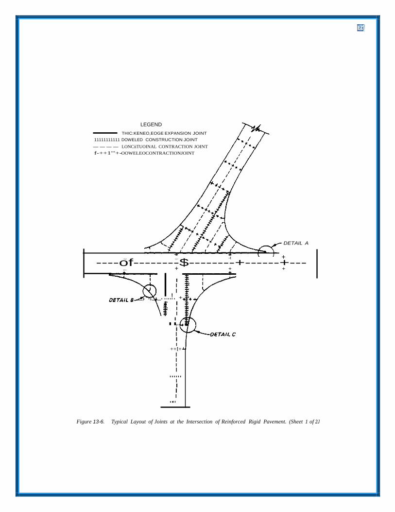
..I
I
LEGEND
THIC:KENEO,EOGE EXPANSION JOINT
11111111111 DOWELED CONSTRUCTION JOINT
---- LONCiiTUOINAL CONTRACTION JOINT
f-++1"'+-OOWELEOCONTRACTIONJOINT
DETAIL A
.,. .,.. -t +
----of--------$--------+------+--- ... + + +
I I I
_, -.,_,_. .....!. +
I I I
,.. I I I I
++I+ I I I
....I.. I I
....I
Figure 13-6. Typical Layout of Joints at the Intersection of Reinforced Rigid Pavement. (Sheet 1 of 2J

FILLET
THICKENED- EDGE
EXPANSION JOINT
TRAFFIC LANE
--..;lllo -CONSTRUCTION OR LONGITUDINAL CONTRACTION JOINT
DOWELED CONSTRUCTION JOINT
DETAILS
DOWELED CONTRACTION JOINT
DOWELED
CONTRACTION JOINT
DETAIL C
Figure 13-6. Typical Layout of Joints at the Intersection of Reinforced Rigid Pavement. (Sheet 2 of 2)

CHAPTER 14
PAVEMENT OVERLAYS
14-1. General. repaired prior to the overlay. Such repair is
Normally, overlays of existing pavements are used to increase the load-carrying capacity of an existing pavement or to correct a defective surface condition on the existing pavement. Of these reasons, the first requires a structural design procedure for determining the thickness of overlay; whereas the second requires only a thickness of overlay suffi- cient to correct the surface condition, and no in- crease in load-carrying capacity is considered. The design method for overlays included in this chap- ter determines the thickness required to increase load-carrying capacity. These methods have been developed from a series of full-scale accelerated traffic tests on various types of overlays and are, therefore, empirical. These methods determine the required thickness of overlay that, when placed on the existing pavement, will be equivalent in per- formance to the required design thickness of a new pavement placed on subgrade.
14-2. Definitions and Symbols for Overlay Pavement Design.
The following terms and symbols apply to the design of overlay pavements.
a. Rigid base pavement. An existing rigid pave- ment is one on which an overlay is to be placed.
b. Flexibile base pavement. Existing pavementto be overlaid is composed of bituminous concrete, base, and subbase courses.
c. Composite pavement. Existing pavement to beoverlaid with rigid pavement is composed of an all- bituminous or flexible overlay on a rigid base pavement.
d. Overlay pavement A pavement constructed onan existing base pavement to increase load-carrying capacity or correct a surface defect.
e. Rigid overlay. A rigid pavement used tostrengthen an existing flexible or rigid pavement.
f. Flexible overlay. A flexible pavement (eitherall-bituminous or bituminous with base course) used to strengthen an existing rigid or flexible pavement.
14-3. Preparation of Existing Pavement.
Exploration and tests of the existing pavement should be made to locate all areas of distress in the existing pavement and to determine the cause of the distress. Areas showing extensive and progressive cracking, rutting, and foundation failures should be
especially needed in areas where excessive pumping, bleeding of water at joints or cracks, excessive settlement in foundation, subgrade rut- ting, surface rutting, and slides have occurred. If testing of the existing pavement indicates the pres- ence of voids beneath a rigid pavement, they should be filled by grouting prior to the overlay. The properties of the existing pavement and foundation such as the modulus of subgrade reaction, CBR, thickness, condition index, and flexural strength should be determined. The exact properties to be determined will depend upon the type of overlay to be used. The surface of the existing pavement should be conditioned for the various types of overlays as follows.
a. Rigid overlay. Overlay thickness criteria arepresented for three conditions of bond between the rigid overlay and existing rigid pavement: fully bonded, partially bonded, and nonbonded. The fully bonded condition is obtained when the concrete is cast directly on concrete and special efforts are made to obtain bond. The partially bonded condition is obtained when the concrete is cast directly on concrete with no special efforts to achieve or destroy bond. The nonbonded condition is obtained when the bond is prevented by an in- tervening layer of material. When a fully bonded or partially bonded rigid overlay is to be used, the existing rigid pavement will be cleaned of all foreign matter (such as oil and paint), spalled concrete, extruded joint seal, bituminous patches, or anything else that would act as a bond-breaker be- tween the overlay and existing rigid pavement. In addition, for the- fully bonded overlay, the surface of the existing pavement must be prepared according to the recommendation in TM 5-822-7. A sand-cement grout or an epoxy grout is applied to the cleaned surface just prior to placement of the concrete overlay. When a nonbonded rigid overlay is being used, the existing rigid pavement will be cleaned of all loose particles and covered with a leveling or bond-breaking course of bituminous concrete, sand- asphalt, heavy building paper, polyethylene, or other similar stable material. The bond-breaking medium generally should not exceed a thickness of about 1 inch except in the case of leveling courses where greater thicknesses may be necessary. When a rigid overlay is being applied to an existing flexible pavement, the surface of the existing pavement will

be cleaned of loose materials, and any potholing or unevenness exceeding about 1 inch will be repaired by cold planing or localized patching or the application of a leveling course using bituminous concrete, sand-asphalt, or a similar material.
b. Flexible overlay. When a flexible overlay isused, no special treatment of the surface of the ex- isting rigid pavement will be required, other than the removal of loose material. When the flexible overlay is all-bituminous concrete, the surface of the existing rigid pavement will be cleaned of all foreign matter, spalled concrete, fat spots in bituminous patches, and extruded soft or spongy joint seal material. Joints or cracks less than 1 inch wide in the existing rigid pavement will be filled with joint sealant. Joints or cracks that are 1 inch or greater in width will be cleaned and filled with an acceptable bituminous mixture (such as sand asphalt) which is compatible with the overlay. Leveling courses of bituminous concrete will be used to bring the existing rigid pavement to the proper grade when required. Prior to placing the all-bituminous concrete, a tack coat will be applied to the surface of the existing pavement.
14-4. Condition of Existing Rigid Pavement.
a. General. The support that the existing rigidpavement will provide to an overlay is a function of its structural condition just prior to the overlay. In the overlay design equations, the structural condition of the existing rigid pavement is assessed by a condition factor C. The value of C should be selected based upon a condition survey (TM 5-826- 6/AFR 93-5) of the existing rigid pavement. Inter- polation of C values between those shown below may be used if it is considered necessary to define more accurately the existing structural condition.
b. Plain concrete overlay. The following valuesof C are assigned for the following conditions of plain and reinforced concrete pavements.
(1) Condition of Existing Plain Concrete Pavement:
C = 1.00 — Pavements are in good condi- tion with little or no structural cracking due to load.
C = 0.75 — Pavements exhibit initial cracking due to load but no progressive cracking or faulting of joints or cracks.
C = 0.35 — Pavements exhibit progressive cracking due to load accompanied by spalling, raveling, or faulting of cracks and joints.
(2) Condition of Existing Reinforced Concrete Pavement:
C = 1.00 — Pavements are in good condi- tion with little or no short-spaced transverse (1-to 2-foot) cracks, no longitudinal cracking, and little spalling or raveling along cracks.
C = 0.75 — Pavements exhibit short- spaced transverse cracking but little or no interconnecting longitudinal cracking due to load and only moderate spalling or raveling along cracks.
C = 0.35—Pavements exhibit severe short- spaced transverse cracking and intercon- necting longitudinal cracking due to load, severe spalling along cracks, and initial punchout-type failures.
c. Flexible Overlay. The following values of Care assigned for the following conditions of plain and reinforced concrete pavement.
(1) Condition of Existing Plain Concrete Pavements:
C = 1.00 — Pavements are in good condi- tion with some cracking due to load but little or no progressive-type cracking.
C = 0.75 — Pavement exhibit progressive cracking due to load and spalling, raveling, and minor faulting at joints and cracks.
C = 0.50—Pavements exhibit multiple cracking along with raveling, spalling, and faulting at joints and cracks
(2) Condition of Existing Reinforced Concrete Pavement.
C = 1.00 — Pavements are in good condi- tion but exhibit some closely spaced load-induced transverse cracking, initial interconnecting longitudinal cracks, and moderate spalling or raveling of joints and cracks.
C = 0.75 — Pavements in trafficked areas exhibit numerous closely spaced load- induced transverse and longitudinal cracks, rather severe spalling or raveling, or initial evidence of punchout failures.
14-5. Rigid Overlay of Existing Rigid Pavement.
a. General. There are three basic equations forthe design of rigid overlays which depend upon the
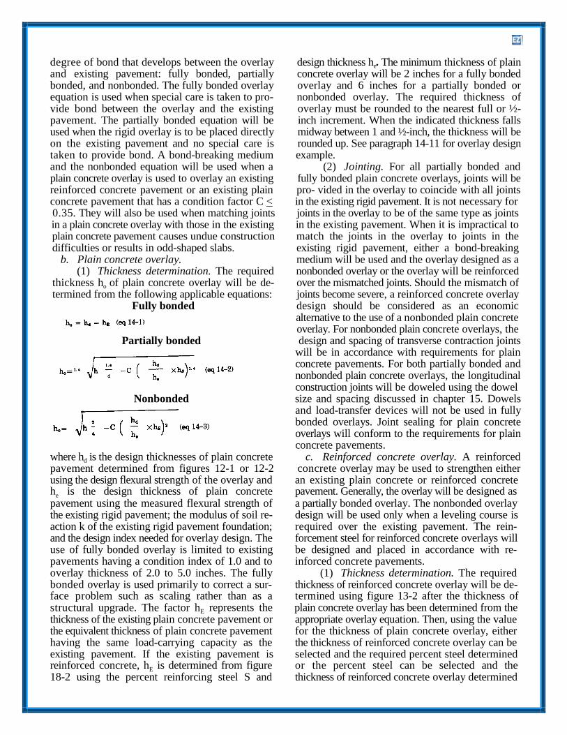
degree of bond that develops between the overlay design thickness he. The minimum thickness of plain and existing pavement: fully bonded, partially concrete overlay will be 2 inches for a fully bonded bonded, and nonbonded. The fully bonded overlay overlay and 6 inches for a partially bonded or equation is used when special care is taken to pro- nonbonded overlay. The required thickness of vide bond between the overlay and the existing overlay must be rounded to the nearest full or ½- pavement. The partially bonded equation will be inch increment. When the indicated thickness falls used when the rigid overlay is to be placed directly midway between 1 and ½-inch, the thickness will be on the existing pavement and no special care is rounded up. See paragraph 14-11 for overlay design taken to provide bond. A bond-breaking medium example. and the nonbonded equation will be used when a (2) Jointing. For all partially bonded and plain concrete overlay is used to overlay an existing fully bonded plain concrete overlays, joints will be reinforced concrete pavement or an existing plain pro- vided in the overlay to coincide with all joints concrete pavement that has a condition factor C < in the existing rigid pavement. It is not necessary for 0.35. They will also be used when matching joints joints in the overlay to be of the same type as joints in a plain concrete overlay with those in the existing in the existing pavement. When it is impractical to plain concrete pavement causes undue construction match the joints in the overlay to joints in the difficulties or results in odd-shaped slabs. existing rigid pavement, either a bond-breaking
b. Plain concrete overlay. medium will be used and the overlay designed as a (1) Thickness determination. The required nonbonded overlay or the overlay will be reinforced
thickness ho of plain concrete overlay will be de- over the mismatched joints. Should the mismatch of termined from the following applicable equations: joints become severe, a reinforced concrete overlay
Fully bonded design should be considered as an economic alternative to the use of a nonbonded plain concrete overlay. For nonbonded plain concrete overlays, the
Partially bonded design and spacing of transverse contraction joints will be in accordance with requirements for plain concrete pavements. For both partially bonded and nonbonded plain concrete overlays, the longitudinal construction joints will be doweled using the dowel
Nonbonded size and spacing discussed in chapter 15. Dowels and load-transfer devices will not be used in fully bonded overlays. Joint sealing for plain concrete overlays will conform to the requirements for plain concrete pavements.
where hd is the design thicknesses of plain concrete c. Reinforced concrete overlay. A reinforcedpavement determined from figures 12-1 or 12-2 concrete overlay may be used to strengthen either using the design flexural strength of the overlay and an existing plain concrete or reinforced concrete he is the design thickness of plain concrete pavement. Generally, the overlay will be designed as pavement using the measured flexural strength of a partially bonded overlay. The nonbonded overlay the existing rigid pavement; the modulus of soil re- design will be used only when a leveling course is action k of the existing rigid pavement foundation; required over the existing pavement. The rein- and the design index needed for overlay design. The forcement steel for reinforced concrete overlays will use of fully bonded overlay is limited to existing be designed and placed in accordance with re- pavements having a condition index of 1.0 and to inforced concrete pavements. overlay thickness of 2.0 to 5.0 inches. The fully (1) Thickness determination. The required bonded overlay is used primarily to correct a sur- thickness of reinforced concrete overlay will be de- face problem such as scaling rather than as a termined using figure 13-2 after the thickness of structural upgrade. The factor hE represents the plain concrete overlay has been determined from the thickness of the existing plain concrete pavement or appropriate overlay equation. Then, using the value the equivalent thickness of plain concrete pavement for the thickness of plain concrete overlay, either having the same load-carrying capacity as the the thickness of reinforced concrete overlay can be existing pavement. If the existing pavement is selected and the required percent steel determined reinforced concrete, hE is determined from figure or the percent steel can be selected and the 18-2 using the percent reinforcing steel S and thickness of reinforced concrete overlay determined
from figure 13-2. The minimum thickness of reinforced concrete overlay will be 4 inches.
(2) Jointing. Whenever possible, the longitudinal construction joints in the overlay should match the longitudinal joints in the existing pavement. All longitudinal joints will be doweled with dowel size and spacing designated in chapter 15 using the thickness of reinforced concrete overlay. It is not necessary for transverse joints in the overlay to match joints in the existing pavement; however, when practical, the joints should be matched. The maximum spacing of transverse con- traction joints will be determined in accordance with equation 16-1, but it will not exceed 75 feet regardless of the thickness of the pavement or the percent steel used. Joint sealing for reinforced con- crete pavements will conform to the requirements for plain concrete pavements.
14-6. Rigid Overlay of Existing Flexible or Composite Pavements.
a. Flexible pavements. A rigid overlay of an ex- isting flexible pavement should be designed in the same manner as a rigid pavement on grade. A modulus of subgrade reaction k should be deter- mined by a plate-bearing test made on the surface of the existing flexible pavement. If not practicable to determine k from a plate-bearing test, an approximate value may be determined using figure 9-1. Figure 9-1 yields an effective k value at the surface of the flexible pavement as a function of the subgrade k and thickness of base and sub- base above the subgrade. When using figure 9-1, the bituminous concrete is considered to be unbound base course material. Using this k value and the concrete flexural strength, the required thickness of plain concrete overlay is determined from figure 12- 1 or 12-2. However, the following limitations should apply:
(1) In no case should a k value greater than 500 pci be used.
(2) The plate-bearing test to determine the k value should be performed on the flexible pavement at a time when the temperature of the bituminous concrete is of the same order as the ambient temperature of the hottest period of the year in the locality of the proposed construction.
b. Composite base pavements. Two conditionsof composite pavement can be encountered when considering a rigid overlay. When the composite pavement is composed of a rigid base pavement with less than 4 inches of all-bituminous overlay, the required thickness of rigid overlay should be determined using the nonbonded overlay equation. If the composite pavement is composed of a rigid
base pavement with 4 inches or more of either all- bituminous or bituminous with base course overlay, the required thickness of overlay should be de- termined by paragraph 14-6a. The same limitations for maximum k value and temperature of pavement at the time of test should apply.
14-7. Flexible Overlay of Flexible Pavement.
Overlays are used for strengthening or rehabilitation of an existing pavement. Strengthening is required when heavier loads are introduced or when a pavement is no longer capable of supporting the loads for which it was designed. Rehabilitation may include sealing or resealing of cracks, patching, limited reconstruction prior to an overlay, res- toration of the surface profile, improvement of skid resistance by a friction course, or improvement of the surface quality. When it has been determined that strengthening is required, the design of an overlay will be accomplished by initially designing a new pavement and comparing its thickness with the thickness of the existing pavement. The difference between these two pavements is the thickness of overlay required to satisfy design requirements. Overlays may be all-bituminous concrete or AC and base course. The flexible pavement after being overlaid shall meet all compaction requirements of a new pavement. Where the existing construction is complex, con- sisting of several layers, and especially where there are semirigid layers, such as soil cement, cement- stabilized soils, or badly cracked portland cement concrete, careful exercise of judgment will be necessary to evaluate the existing materials. Guidance for evaluating existing construction is given in TM 5-826-2/AFM 88-24, Chap 2.
14-8. Flexible Overlay of Rigid Base Pavement.
a. Design procedure. The design procedure pre- sented determines the thickness of flexible overlay necessary to increase the load-carrying capacity of existing rigid pavement. This method is limited to the design of the two types of flexible overlay, the all-bituminous and the bituminous with base course. The selection of the type of flexible overlay to be used for a given condition is dependent only on the required thickness of the overlay. Normally, the bituminous with base course overlay should be used when the required thickness of overlay is sufficient to incorporate a minimum 4-inch compacted layer of high-quality base-course material plus the required thickness of bituminous concrete surface courses. For lesser thicknesses of flexible overlay, the all-bituminous overlay should be used. The method of design is referenced to the deficiency in
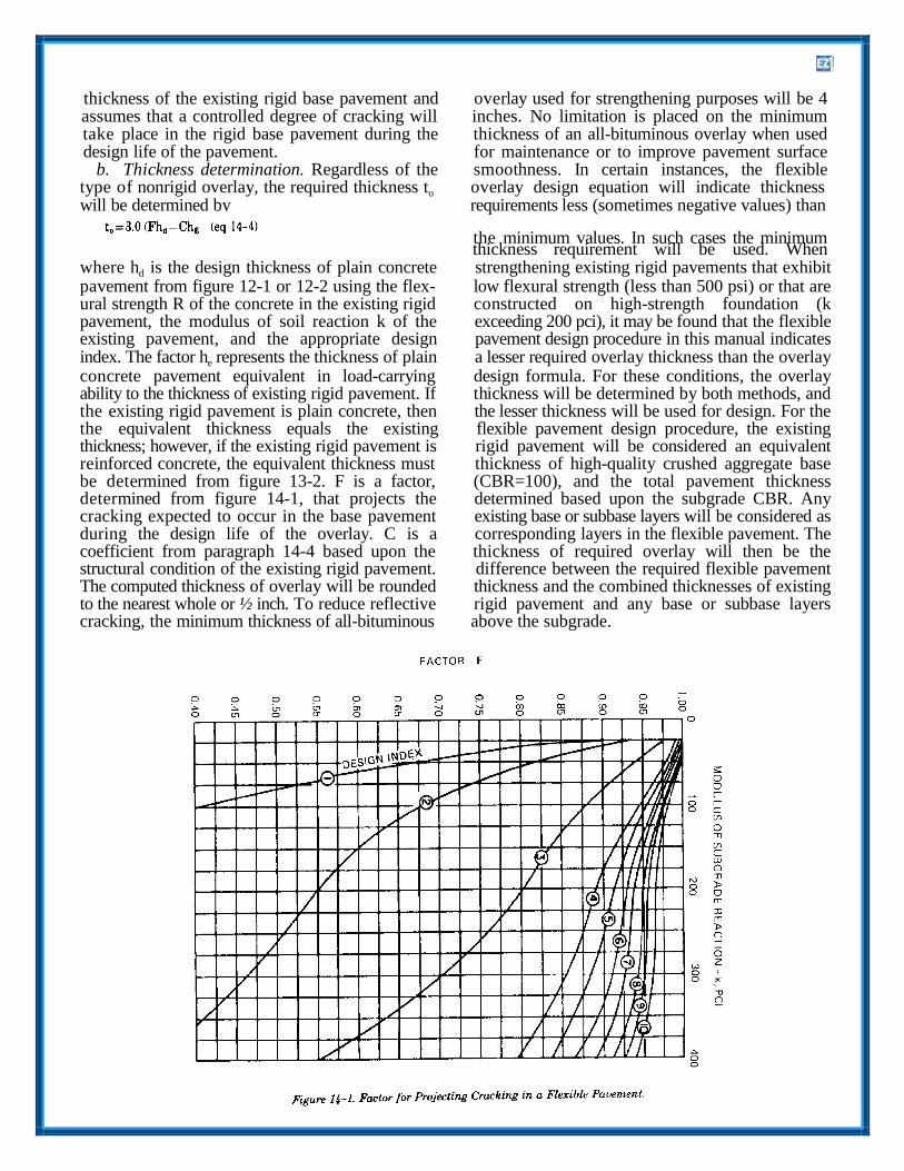
thickness of the existing rigid base pavement and overlay used for strengthening purposes will be 4 assumes that a controlled degree of cracking will inches. No limitation is placed on the minimum take place in the rigid base pavement during the thickness of an all-bituminous overlay when used design life of the pavement. for maintenance or to improve pavement surface
b. Thickness determination. Regardless of the smoothness. In certain instances, the flexible type of nonrigid overlay, the required thickness to overlay design equation will indicate thickness will be determined by requirements less (sometimes negative values) than
the minimum values. In such cases the minimum thickness requirement will be used. When
where hd is the design thickness of plain concrete strengthening existing rigid pavements that exhibit pavement from figure 12-1 or 12-2 using the flex- low flexural strength (less than 500 psi) or that are ural strength R of the concrete in the existing rigid constructed on high-strength foundation (k pavement, the modulus of soil reaction k of the exceeding 200 pci), it may be found that the flexible existing pavement, and the appropriate design pavement design procedure in this manual indicates index. The factor he represents the thickness of plain a lesser required overlay thickness than the overlay concrete pavement equivalent in load-carrying design formula. For these conditions, the overlay ability to the thickness of existing rigid pavement. If thickness will be determined by both methods, and the existing rigid pavement is plain concrete, then the lesser thickness will be used for design. For the the equivalent thickness equals the existing flexible pavement design procedure, the existing thickness; however, if the existing rigid pavement is rigid pavement will be considered an equivalent reinforced concrete, the equivalent thickness must thickness of high-quality crushed aggregate base be determined from figure 13-2. F is a factor, (CBR=100), and the total pavement thickness determined from figure 14-1, that projects the determined based upon the subgrade CBR. Any cracking expected to occur in the base pavement existing base or subbase layers will be considered as during the design life of the overlay. C is a corresponding layers in the flexible pavement. The coefficient from paragraph 14-4 based upon the thickness of required overlay will then be the structural condition of the existing rigid pavement. difference between the required flexible pavement The computed thickness of overlay will be rounded thickness and the combined thicknesses of existing to the nearest whole or ½ inch. To reduce reflective rigid pavement and any base or subbase layers cracking, the minimum thickness of all-bituminous above the subgrade.
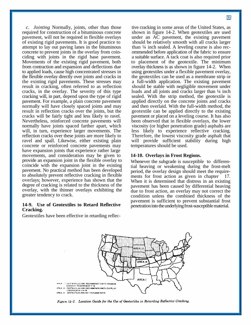
c. Jointing Normally, joints, other than those tive cracking in some areas of the United States, as required for construction of a bituminous concrete shown in figure 14-2. When geotextiles are used pavement, will not be required in flexible overlays under an AC pavement, the existing pavement of existing rigid pavements. It is good practice to should be relatively smooth with all cracks larger attempt to lay out paving lanes in the bituminous than ¼ inch sealed. A leveling course is also rec- concrete to prevent joints in the overlay from coin- ommended before application of the fabric to ensure ciding with joints in the rigid base pavement. a suitable surface. A tack coat is also required prior Movements of the existing rigid pavement, both to placement of the geotextile. The minimum from contraction and expansion and deflections due overlay thickness is as shown in figure 14-2. When to applied loads, cause high concentrated stresses in using geotextiles under a flexible pavement overlay, the flexible overlay directly over joints and cracks in the geotextiles can be used as a membrane strip or the existing rigid pavements. These stresses may a full-width application. The existing pavement result in cracking, often referred to as reflection should be stable with negligible movement under cracks, in the overlay. The severity of this type loads and all joints and cracks larger than ¼ inch cracking will, in part, depend upon the type of rigid sealed. With the strip method, the geotextile is pavement. For example, a plain concrete pavement applied directly on the concrete joints and cracks normally will have closely spaced joints and may and then overlaid. With the full-width method, the result in reflection cracks over the joints, but the geotextile can be applied directly to the existing cracks will be fairly tight and less likely to ravel. pavement or placed on a leveling course. It has also Nevertheless, reinforced concrete pavements will been observed that in flexible overlays, the lower normally have joints spaced farther apart, which viscosity (or higher penetration grade) asphalts are will, in turn, experience larger movements. The less likely to experience reflective cracking. reflection cracks over these joints are more likely to Therefore, the lowest viscosity grade asphalt that ravel and spall. Likewise, either existing plain will provide sufficient stability during high concrete or reinforced concrete pavements may temperatures should be used. have expansion joints that experience rather large movements, and consideration may be given to 14-10. Overlays in Frost Regions. provide an expansion joint in the flexible overlay to coincide with the expansion joint in the existing pavement. No practical method has been developed to absolutely prevent reflective cracking in flexible overlays; however, experience has shown that the degree of cracking is related to the thickness of the overlay, with the thinner overlays exhibiting the greater tendency to crack.
14-9. Use of Geotextiles to Retard Reflective Cracking.
Geotextiles have been effective in retarding reflec-
Whenever the subgrade is susceptible to differen- tial heaving or weakening during the frost-melt period, the overlay design should meet the require- ments for frost action as given in chapter 17. When it is determined that distress in an existing pavement has been caused by differential heaving due to frost action, an overlay may not correct the condition unless the combined thickness of the pavement is sufficient to prevent substantial frost penetration into the underlying frost-susceptible material.

14-11. Overlay Design Example.
Design an overlay for an existing road having a plain concrete thickness of 6 inches, a flexural strength of 650 psi, a subgrade k value of 100 pci, and a design index of 8. The concrete overlay will also have a flexural strength of 650 psi. The factor for projecting cracking in a flexible overlay is 0.975 from figure 14-1. The existing pavement is in good condition with little or no structural cracking. The condition factor C is therefore equal to 1.0 for concrete and flexible overlay. From figure 12-1, hd
ho = 4.4 inches (use minimum thickness of 6 inches)
Unbonded Overlay
and he are 8.6 inches. Overlay thickness requirements for the various types of overlays are as follows:
ho = hd - hg
ho = 8.6 - 6.0
Bonded Overlay ho = 6.16 inches (round to 6.5 inches)
Flexible Overlay
ho = 2.6 inches (round to 3.0 inches)
Partially Bonded Overlay
to =3.0((Fhd - Chg)
to = 3.0(0.975 × 8.6 - 1.0 × 6)
to = 7.2 inches (round to 7.5 inches)

CHAPTER 15
JOINTS FOR PLAIN CONCRETE
15-1. Design Details.
A typical layout and cross section of a roadway is presented in figure 15-1 showing the location of various joint types. Figure 13-1 presents a layout of joints at intersections of plain concrete pavements. Figure 15-2 shows the layout of joints for plain concrete parking areas. Joints for RCCP are discussed in chapter 17.
15-2. Joint Types and Usage.
Joints are provided to permit contraction and ex-
pansion of the concrete resulting from temperature
and moisture changes, to relieve warping and
curling stresses due to temperature and moisture
differentials, to prevent unsightly irregular breaking
of the pavement, and as a construction expedient, to
separate sections or strips of concrete placed at
different times. The three general types of joints are
contraction, construction, and expansion (see figs.
15-3 to 15-6.

SHOULDER TR FIC LANE TR FIC LANE
CURB 8t GUTTER
BUTT CONSTRUcriON JOINT WITH TIE BAAS OR CONTRN:T/ON JOINT WITH TIE BAAS
CROSS SECTION
CONSTRUCTION OR CONTRN:TION JOINT WITH TIE BAAS
fXJNEL£0 CONTRN:TION JOINTS fCLASS A 8t B ROADS 8t STREETS ONLYJ
PLAN VIEW
--DOWEL:
Z TIE BAR: NO.5 DEFORMED STEEL BARS,
JO" IN LENGTH, N'ID SPACED ON
JO" CENTERS
Figure 15-1. Design Details for Plain Concrete Pavements. (Sheet 1 of 2)

CURB&
GUTTER
TRAFFIC
LONGITUDINAL CONTRACTION
JOINT WITH TIE BARS
CROSS- SECTION
CONSTRUCTION JOINT
WITH TIE BARS
PARKING
TRAFFIC
TRAFFIC
CONTRACTION
JOINT, DOWELED
FOR CLASS
A & BROADS
AND STREETS
ONLY
PARKING
PLAN- VIEW
LONGITUDINAL CONTRACTION
JOINT WITH TIE BARS
-DOWEL:
Z TIE BAR: NO.5 DEFORMED STEEL BARS.
JO" IN LENGTH, AND SPACED ON JO" CENTERS.
Figure 15-1. Design Details for Plain Concrete Pavements. (Sheet 2 of 2)

Figure 15-2. Joint Layout for Vehicular Parking Areas.

Figure 15-3. Contraction Joints for Plain C<Jncrete Pavements.

Figure 15-4. Construction Joints for Plain Concrete Pavements. (Sheet 1 of 4)

Figure 15-4,. Construction Joints for Plain Concrete Pavements. (Sheet 2 of ,4)

JOINT SEALANT DETAIL
(FIGURE 15-7)
'>.:::. ':. ::·."! ..... ;.
.. 5'MIN
e. THICKENED EDGE LONGITUDINAL
JOINT SEALANT DETAIL
(FIGURE 15-7)
EXISTING
PAVEMENT -<":
6"M/N OR
1.25 hd- he
NO.5 DEFORMED STEEL BARS 2' LONG,
SPACED ON 1'-6" CENTERS, AND
PLACED PARALLEL TO THICKENED
EDGE
NOTE:
PLACEMENT AND CONSOUDATION OF
THE NEW CONCRETE UNDER EXISTING
PAVEMENT SHOULD BE CARRIED OUT
IMMEDIATELY PRIOR TO CONSTRUCTION
OF THE NEW PAVEMENT, PLACEMENT
OPERATIONS SHOULD BE TIMED SO
THAT THE INITIAL CONCRETE IS STILL
PLASTIC WHEN THE REMAINDER OF THE
CONCRETE PAVEMENT IS PLACED.
. f. SPECIAL JOINT BETWEEN NEW AND EXISTING PAVEMENT
TRANSVERSE OR LONGITUDINAL
Figure 15-.4. Construction Joints for Plain Concrete Pavements. (Sheet 3 of 4J

Figure 15-4. Construction Joints for Plain Concrete Pavements. (Sheet 4 of 4J

Figure 15-5. Expansion Joints for Plain Concrete Pavements.
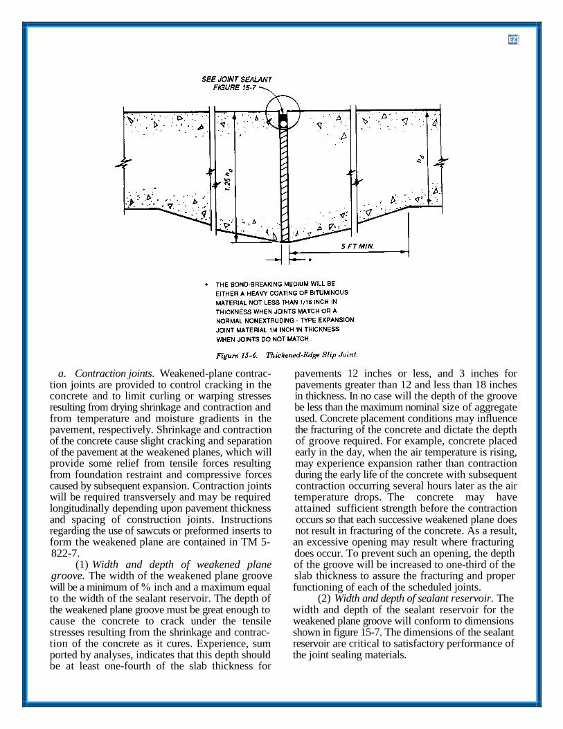
a. Contraction joints. Weakened-plane contrac- pavements 12 inches or less, and 3 inches for tion joints are provided to control cracking in the pavements greater than 12 and less than 18 inches concrete and to limit curling or warping stresses in thickness. In no case will the depth of the groove resulting from drying shrinkage and contraction and be less than the maximum nominal size of aggregate from temperature and moisture gradients in the used. Concrete placement conditions may influence pavement, respectively. Shrinkage and contraction the fracturing of the concrete and dictate the depth of the concrete cause slight cracking and separation of groove required. For example, concrete placed of the pavement at the weakened planes, which will early in the day, when the air temperature is rising, provide some relief from tensile forces resulting may experience expansion rather than contraction from foundation restraint and compressive forces during the early life of the concrete with subsequent caused by subsequent expansion. Contraction joints contraction occurring several hours later as the air will be required transversely and may be required temperature drops. The concrete may have longitudinally depending upon pavement thickness attained sufficient strength before the contraction and spacing of construction joints. Instructions occurs so that each successive weakened plane does regarding the use of sawcuts or preformed inserts to not result in fracturing of the concrete. As a result, form the weakened plane are contained in TM 5- an excessive opening may result where fracturing 822-7. does occur. To prevent such an opening, the depth
(1) Width and depth of weakened plane of the groove will be increased to one-third of the groove. The width of the weakened plane groove slab thickness to assure the fracturing and proper will be a minimum of inch and a maximum equal functioning of each of the scheduled joints. to the width of the sealant reservoir. The depth of (2) Width and depth of sealant reservoir. The the weakened plane groove must be great enough to width and depth of the sealant reservoir for the cause the concrete to crack under the tensile weakened plane groove will conform to dimensions stresses resulting from the shrinkage and contrac- shown in figure 15-7. The dimensions of the sealant tion of the concrete as it cures. Experience, sum reservoir are critical to satisfactory performance of ported by analyses, indicates that this depth should the joint sealing materials. be at least one-fourth of the slab thickness for

JOINT SPACING
FT
WIDTH. IN
MIN MAX
<25
25- 50
>so
112
J/4
1.0
518
1 ·a 1-1 8
CONTRACTION JOINT CONSTRUCTION JOINT EXPANSION JOINT
, .
JOINT
BOTTOM
INSERT
CRACK
W.WIDTH OF SEAlANT RESERVOIR (SEE TABLE)
D.DEPTH OF SEAlANT (1.0 TO 1.5 X W) T.DEPTH OF INITIAL SAWCUT OR INSERT TYPE JOINT FORMER ,CONTRACTION JOINT)
a 11• SlAB THICKNESS FOR PAVEMENTS LESS THAN 12 INCHES
b J INCHES FOR PAVEMENTS 12-18 INCHES'
c 1/6 SlAB THICKNESS FOR PAVEMENTS MORE THAN 18 INCHES'
TABLE 'CJESIGNER MAY WANT TO CONSIDER
REQUIRING 1/4 SLAB THICKNESS
NOTE TQP OF SEALANT WILL BE 1 B-IN TO 114-IN. BELOW TOP OF
PAVEMENT
Figure 15-7. Joint Sealant Details. (Sheet 1 of 3)

JOINT SPACING
FT
WIDTH IN.
MIN I MAX
<25
25-50
>!>0
1/2
3/4
1.0
!>/8
7/8
1-1/8
CONTRACTION JOINT CONSTRUCTION JOINT EXPANSION JOINT
1
CRACK
W • WIDTH OF SEALANT RESERVOIR (SEE TABLE)
D • DEPTH OF SEALA NT (1.0 TO 1.5 X W)
T • DEPTH OF INITIAL SAWCUT OR INSERT TYPE JOINT FORMER lCONTRACTION JOINT)
a. 1/4 SLAB THICKNESS FOR PAVEMENTS LESS THAN 12 INCHES
b. 3 INCHES FOR PAVEMENTS 12·18 INCHES'
c. 1/6 SLAB THICKNESS FOR PAVEMENTS MORE THAN 181NCHES'
TABLE "DESIGNER MAY WANT TO CONSIDER
REQUIRING 1/4 SLAB THICKNESS
NOTE TOP OF SEALANT WILL BE 118-IN. TO 114-IN. BELOW TOP OF
PAVEMENT
Figure 15-7. Joint Sealant Details. (Sheet 2 of 3)

(3) Spacing of transverse contraction joints. pavement thickness, thermal coefficient and other Transverse contraction joints will be constructed characteristics of the aggregate and concrete, across each paving lane perpendicular to the center climatic conditions, and foundation restraint. It is line, at intervals of not less than 12 ½ feet, and impractical to establish limits on joint spacing that generally not more than 25 feet (20 feet for Air are suitable for all conditions without making them Force). In regions where the design freezing index unduly restrictive. The joint spacings in table 15-1 is 1,800 or more degree days the maximum spacing have given satisfactory control of transverse should be 20 feet. The joint spacing will be uniform cracking in most instances and should be used as a throughout any major paved area, and each joint guide, subject to modification based on available will be straight and continuous from edge to edge of information regarding the performance of existing the paving lane and across all paving lanes for the pavements in the vicinity or unusual properties of full width of the paved area. Staggering of joints in the concrete. For best pavement performance, the adjacent paving lanes can lead to sympathetic number of joints should be kept to a minimum by cracking and will not be permitted unless using the greatest joint spacing that will reinforcement is used. The maximum spacing of satisfactorily control cracking. However, experience transverse joints that will effectively control has shown that oblong slabs, especially in thin cracking will vary appreciably depending on pavements, tend to crack into smaller slabs of nearly

equal dimensions under traffic. Therefore, it is desirable, insofar as practicable, to keep the length and width dimensions as nearly equal as possible. In no case should the length dimension (in the direction of paving) exceed the width dimension more than 25 percent. Where it is desired to exceed the joint spacing (in table 15-1), a request must be submitted to HQUSACE (CEMP-ET) or the appropriate Air Force Major Command outlining local conditions that indicate that the proposed change in joint spacing is desirable.
(b) For plain concrete pavements, deformed tie bars will be required in longitudinal contraction joints that fall 15 feet or less from the free edge of paved areas that are 100 feet or greater in width. The deformed tie bars will be inch in di- ameter, 30 inches long, and spaced on 30-inch cen- ters. In addition, longitudinal contraction joints placed along the center line of paving lanes that have a width greater than the maximum spacing of transverse contraction joints will be tied using tie bars of the above-mentioned dimensions (fig 15-3).
b. Construction joints. Construction joints may(4) Spacing of longitudinal contraction be required in both the longitudinal and trans-verse
joints. Contraction joints will be placed along the directions. Longitudinal construction joints, center line of paving lanes that have a width greater generally spaced 20 to 25 feet apart but which may than the determined maximum spacing of trans- reach 50 feet apart, depending on construction verse contraction joints in table 15-1. These joints equipment capability, will be provided to separate may also be required in the longitudinal direction successively placed paving lanes. Transverse con- for overlays, regardless of overlay thickness, to struction joints will be installed at the end of each match joints existing in the base pavement unless a day’s paving operation, and at other points within a bond-breaking medium is used between the overlay paving lane where the placing of concrete is dis- and base pavement or the overlay pavement is continued a sufficient length of time for the con- reinforced. crete to start to set. All transverse construction
joints should be located in place of other regularly spaced transverse joints (contraction or expansion
(5) Doweled and tied contraction joints. types). There are several types of construction joints available for use, as shown in figure 15-4 and as described below. The selection of the type of
(a) Dowels are required in transverse con- construction joint will depend on such factors as the traction joints for plain concrete pavements for class concrete placement procedure (formed or slip- A and B roads and streets, reinforced concrete formed) and foundation conditions. pavements that use slab lengths greater than those (1) Doweled joint. The doweled joint is the in table 15-1, and in the last joint at ends of long best joint for providing load transfer and paving lanes such as large storage and parking maintaining slab alignment. It is a desirable joint for areas. These dowels are required to ensure good the most adverse conditions such as heavy loading, joint load transfer under heavy, repeated loads and high traffic intensity, and lower strength under conditions where conventional contraction foundations. However, because the alignment and joints may have inadequate load transfer because of placement of the dowel bars are critical to excessive joint opening. Table 15-2 presents the satisfactory performance, this type of joint is size and spacing of dowels. difficult to construct, especially for slipformed
concrete. However, the doweled joint is required

for all transverse construction joints in plain nonextruding type. The type and thickness of filler concrete pavements. material and the manner of its installation will
(2) Thickened-edge joint. Thickened-edge- depend upon the particular case. Usually, a type joints may be used instead of other types of preformed material of ¾-inch thickness will be joints employing load transfer devices. When the adequate; however, in some instances, a greater thickened-edge joint is constructed, the thickness of thickness of filler material may be required. Filler the concrete at the edge is increased to 125 percent material for slip joints will be either a heavy coating of the design thickness. The thickness is then re- of bituminous material not less than 1/16 inch in duced by tapering from the free-edge thickness to thickness when joints match or a normal the design thickness at a distance of 3 feet from the nonextruding-type material not less than ¼ inch in longitudinal edge. The thickened-edge joint is thickness when joints do not match. Where large considered adequate for the load-induced concrete expansions may have a detrimental effect on stresses. However, the inclusion of a key in the adjoining structures, such as at the juncture of rigid thickened-edge joint (fig 15-4d) provides some and flexible pavements, expansion joints in degree of load transfer in the joint and helps to successive transverse joints back from the juncture maintain slab alignment; although not required, it is should be considered. The depth, length, and recommended for pavement constructed on low-to position of each expansion joint will be sufficient to medium-strength foundations. The thickened-edge form a complete and uniform separation between joint may be used at free edges of paved areas to the pavements or between the pavement and the accommodate future expansion of the facility or structure concerned. where wheel loadings may track the edge of the (1) Between pavement and structures. Expan- pavement. The use of this type joint is contingent sion joints will be installed to surround, or to sepa- upon adequate base-course drainage meeting rate from the pavement, any structures that project requirements of TM 5-820-2/AFM 88-5, Chap 2. through, into, or against the pavements, such as at
(3) Keyed joint. The keyed joint is the most the approaches to buildings or around drainage economical method, from a construction standpoint, inlets. The thickened-edge-type expansion joint will for providing load transfer in the joint. It has been normally be best suited for these places (see fig 15- demonstrated that the key or keyway can be satis- 5). factorily constructed using either formed or slim (2) Within pavements and at pavement inter- formed methods. The required dimensions of the sections. Expansion joints within pavements are joint can best be maintained by forming or slim difficult to construct and maintain and often con- forming the keyway rather than the key. The di- tribute to pavement failures. Their use will be kept mensions and location of the key are critical to its to the absolute minimum necessary to pre- vent performance. Deviations exceeding the stated tol- excessive stresses in the pavement from expansion erances can result in failure in the joint. Keyed joints of the concrete or to avoid distortion of a pavement should not be used in rigid pavements that are less through the expansion of an adjoining pavement. than 9 inches in thickness. Tie bars in the keyed The determination of the need for and spacing of joint will limit opening of the joint and provide expansion joints will be based upon pavement some shear transfer that will improve the thickness, thermal properties of the concrete, performance of the keyed joints. However, tieing all prevailing temperatures in the area, temperatures joints in pavement widths of more than 75 feet can during the construction period, and the experience result in excessive stresses and cracking in the with concrete pavements in the area. Unless needed concrete during contraction. to protect abutting structures, expansion joints will
c. Expansion joints. Expansion joints will be be omitted in all pavements 10 inches or more in used at all intersections of pavements with struc- thickness and also in pavements less than 10 inches tures or with other concrete pavements where in thickness when the concrete is placed during paving lanes are perpendicular to each other, and warm weather since the initial volume of the they may be required within the pavement features. concrete on hardening will be at or near the A special expansion joint, the slip joint, is required maximum. However, for concrete placed during at pavement intersections. The types of expansion cold weather, expansion joints may be used in joints are the thickened-edge joint, the thickened- pavements less than 10 inches thick. edge slip joint, and the doweled type joint (see figs (a) Longitudinal expansion joints within 15-5 and 15-6). Filler material for the thickened- pavements will be of the thickened-edge type (see edge and doweled type expansion joint will be a fig 15-5). Dowels are not recommended in longitu-

dinal expansion joints because differential expansion a. Header. The header may be set on either sideand contraction parallel with the joints may develop of the transition slab with the transverse construc- undesirable localized strains and cause failure of the tion joint doweled, as required. The dowel size and concrete, especially near the corners of slabs at location in the transverse construction joint should transverse joints. Expansion joints are not required be commensurate with the thickness of the pave- between two adjoining pavements where paving ment at the header. lanes of the two pavements are parallel. b. Transition between different joints. When
(b) Transverse expansion joints within there is a transition between a doweled longitudinal pavements will be the doweled type (see fig 15-5). construction joint and a keyed longitudinal There may be instances when it will be desirable to construction joint, the longitudinal construction allow some slippage in the transverse joints such as joint in the transition slab may be either keyed or at the angular intersection of pavements to prevent doweled. The size and location of the dowels or the expansion of one pavement from distorting the keys in the transition slabs should be the same as other. Then, the design of the transverse expansion those in the pavement with the doweled or keyed joints will be similar to the thickened-edge slip joint, respectively. joints (see para 15-6). When a thickened-edge slip c. Transition between two keyed joints. Whenjoint is used at a free edge not perpendicular to a there is a transition between two keyed joints with paving lane, a transverse expansion joint will be different dimensions, the size and location of the provided 75 to 100 feet back from the free edge. key in the transition slab should be based on the
thickness of the thinner pavement. 15-3. Dowels.
The important functions of dowels or any other 15-5. Joint Sealing.
load-transfer device in concrete pavements are to All joints will be sealed to prevent infiltration of help maintain the alignment of adjoining slabs and surface water and solid substances. Details of the to transfer some stresses from loads to the adjacent joint sealant are shown in figure 15-7. A jet-fuel slab, thereby limiting or reducing stresses in the resistant (JFR) sealant, either poured or preformed, loaded slab. Different sizes of dowels will be will be used in the joints of hardstands, washracks, specified for different thicknesses of pavements (see and other paved areas where fuel or other lubricants table 15-2). When extra strength pipe is used for may be spilled during the operation, parking, dowels, the pipe will be filled with either a stiff maintenance, and servicing of vehicles. Sealants that mixture of sand-asphalt or portland cement mortar are not fuel resistant will be used in joints of all or the ends of the pipe will be plugged. If the ends other pavements. Poured JFR sealants will conform of the pipe are plugged, the plug must fit inside the to Federal Specifications SS-S-200E and SS-S- pipe and be cut off flush with the end of the pipe so 1614A, and poured non-JFR sealants will conform that there will be no protruding material to bond to Federal Specification 55-S-1401C. Use of SS-S- with the concrete and prevent free movement of the 1401C requires MACOM approval for use on Air dowel. Figures 15-1 and 13-1 show the dowel Force Projects. Cold poured non-JFR sealants will placement. All dowels will be straight, smooth, and conform to CRD-C 527. Preformed sealants will free from burrs at the ends. One end of the dowel conform to ASTM D 2628 and tested according to will be painted and oiled to prevent bonding with the procedures in appendix C for jet-fuel resistance. the concrete. Dowels used at expansion joints will Lubricant for preformed sealants will conform to be capped at one end, in addition to painting and ASTM D 2835. Preformed sealants must always be oiling, to permit further penetration of the dowels compressed 45 to 85 percent of their original width. into the concrete when the joints close. The selection of pour-able or preformed sealant
should be based upon economics. Compression- 15-4. Special Provisions for Slipform Paving. type preformed sealants are recommended when the
Provisions must be made for slipform pavers when there is a change in longitudinal joint configuration. The thickness may be varied without stopping the paving train, but the joint configuration cannot be
joint spacings exceed 25 feet and are required when joint spacings exceed 50 feet.
15-6. Special Joints and Junctures.
varied without modifying the side forms, which will Situations will develop where special joints or normally require stopping the paver and installing a variations of the more standard type joints will be header. The following requirements shall apply at a needed to accommodate the movements that will pavement transition area. occur and to provide a satisfactory operational sur-
16
16
face. Some of these special joints or junctures are as edge was provided at the free edge of the existing follows: pavement, but neither met the design requirements
a. Slip-type joints. At the juncture of two pave- for the new pavement. ment facilities, expansion and contraction of the (3) For transverse contraction joints, when re- concrete may result in movements that occur in moving and replacing slabs in an existing pavement. different directions. Such movements may create (4) For longitudinal construction joints, when detrimental stresses within the concrete unless removing and replacing slabs in an existing pave- provision is made to allow the movements to occur. ment if the existing load-transfer devices are dam- At such junctures, a thickened-edge slip joint shall aged during the pavement removal. be used to permit the horizontal slip- page to occur. (5) Any other location where it is necessary to The design of the thickened-edge slip joint will be provide load transfer for the existing pavements. similar to the thickened-edge construction joint (see The special joint design may not be required if a fig 15-6). The bond-breaking medium will be either new pavement joins an existing pavement that is a heavy coating of bituminous material not less than grossly inadequate to carry the design load of the 1/ inch in thickness when joints match or a normal new pavement or if the existing pavement is in poor nonextruding-type expansion joint material not less structural condition. If the existing pavement can than ¼ inch in thickness when joints do not match. carry a load that is 75 percent or less of the new The 1/ -inch bituminous coating may be either a pavement design load, special efforts to pro- vide low penetration (60 to 70 grade asphalt) or a clay- edge support for the existing pavement may he type asphalt-base emulsion similar to that used for omitted and the alternate thickened-edge joint used roof coating (see Military Specification MIL-R- (fig 15-4h); however, if omitted, accelerated failures 3472) and will be applied to the face of the joint by in the existing pavement may be experienced. The hand brushing or spraying. new pavement will simply be designed with a
b. Joints between new and existing pavements. thickened edge at the juncture. Any load-transfer A special thickened-edge joint design (see fig 15-4f) devices in the existing pavement should be used at will be used at the juncture of new and existing the juncture to provide as much support as possible pavements for the following conditions: to the existing pavement. Drilling and grouting
(1) When load-transfer devices (keyways or dowels in the existing pavement for edge support dowels) or a thickened edge was not provided at may he considered as an alternate to the special the free edge of the existing pavement. joint; however, a thickened-edge design will be used
(2) When load-transfer devices or a thickened for the new pavement at the juncture.

CHAPTER 16
JOINTS FOR REINFORCED CONCRETE
16-1. Requirements.
Figures 16-1 through 16-3 present details of the
contraction, construction, and expansion joints in
reinforced concrete pavements. Joint requirements
and types of reinforced concrete pavements will be
the same as for plain concrete pavements (see chap
15) except for those listed below.

• :p·.
:·:>:
REINFORCING STEEL IS /
CARRIED THROUGH JOINT--"
.. ... .'J.' .'<f• .'.;..: ·.,_·:: ..
NOTE: SAW CUT Will NOT EXTEND BELOW
STEEL REINFORCING
-"• I"4
a. LONGITUDINAL
Sfifi JOINT SEAU.NT
FIGURE 15-7 REINFORCING STEEL IS NOT CARRIED
THROUGH JOINT
hd o· -2 - 2
3"MAX 3"MAX
EITHER ONE PIECE OR
THREADED SPLIT TYPE
DOWEL MAYSE USED
PAINT AND OIL
ONE END OF
DOWEL
..... . ·_.,-....·. .·.·
o• OF::NOTES DOWEL DIAMETER
b. TRANSVERSE
· ..····· . ·· .' ··.
ha SEE JOINT SEALANT
T FIGURE 15-7
. -· \, . - •• ? - ::_·-
. ·. ·A..
NO.5 DEFORMED STEEL TIE BARS 2'- 6" LONG
AND SPACED 2'- 6" ON CENTERS
c. TIED LONGITUDINAL
Figure 16-1. Contraction Joints for Reinforced Concrete Pavements.

·.-v:: ·. ..
-"• 1"
4 NO GROOVE OR JOINT SEAL PROVIDED
FORMED BUTT JOINT
REINFORCING STEEL IS CARRIED
THROUGH JOINT
DOWEL·BOTH ENOS UNPAINTED AND
NOT OILED
D* DENOTES DOWEL DIAMETER, EITHER ONE PIECE
OR THREADED SPLIT TYPE DOWELS MAY BE USED.
SEE PARAGRAPH 16·1c FOR USE OF THIS JOINT
a. DOWELED TRANSVERSE
SEE JOINT SEALANT FIGURE 15-7
..; .. .·
REINFORCING STEEL IS NOT
CARRIED THROUGH JOINT
·. v·. ,·. · . ·.·b
3"MAX
PAINT AND OIL
ONE END OF DOWEL
. FORMED BUTT JOINT .
·I> b: :"': : : . .
o• DENOTES DOWEL DIAMETER, EITHER ONE PIECE OR
THREADED SPLIT-TYPE DOWELS MAY BE USED
b. DOWELED TRANSVERSE OR LONGITUDINAL
Figure 16-2. Construction Joints for Reinforced Concrete Pavements. (Sheet 1 of )

Figure 16-2. Construction Joints for Reinforced Concrete Pavements. (Sheet 2 of 4J
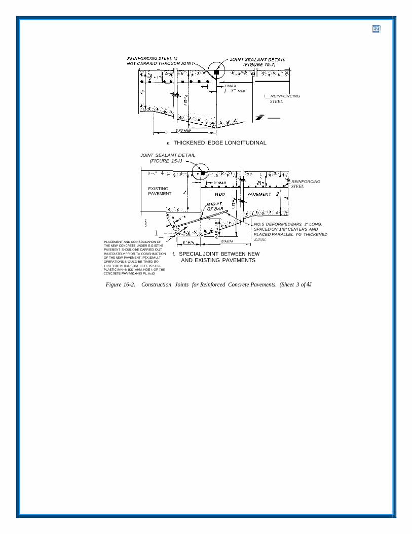
T'MAX
f---3" MA)f
\ REINFORCING
STEEL
i-
e. THICKENED EDGE LONGITUDINAL
JOINT SEALANT DETAIL
(FIGURE 15-lJ
i> ·-." 4- ;.:
EXISTING
PAVEMENT
REINFORCiNG
STEEL
§ 1_----.X
NO.5 DEFORMED BARS. 2' LONG.
SPACED ON 1!6" CENTERS AND
PLACED PARALLEL ro THICKENED
PLACEMENT AND CO!>;SOLIDAHON CF
THE NEW CONCRETE UNDER E:O:ISTIN8 PAVEMENT SHOUL.O hE CARRIED OUT
5'MIN • I
EDGE
IMI.IEOIATELV PRIOR To CONSHIUCTION
OF THE NEW PAVEMENT, P[X:EMU.T
OPERATIONS S CULD BE TIMED $0
THAT THE INITIAL CONCRETE IS STLL PLASTIC INHI<N IKE AHM.INOE A OF THE
CCNCJlETE PAVfM£.•H IS PL.ActD
f. SPECIAL JOINT BETWEEN NEWAND EXISTING PAVEMENTS
Figure 16-2. Construction Joints for Reinforced Concrete Pavements. (Sheet 3 of 4J

:"'I
..
SEE JOINT SEALANT FIGURE 15·7
'I> .·. - : . {:$: ..
EXISTING
PAVEMENT
NEW
5-FTMIN
• NOTE: THIS TYPE JOINT SHOULD BE USED ONLY WHEN
EXISTING PAVEMENT IS TO BE REPLACED IN A
SHORT PERIOD OF TIME, SINCE WITHOUT LOAD
TRANSFER, IT WILL DETERIORATE QUICKLY.
g. THICKENED··EDGED JOINT BETWEENNEW AND EXISTING PAVEMENT
SEE JOINT SEALANT FIGURE 15·7
• • A' .. ·'i7 .•
-i'oq,
EXISTING PAVEMENT
-P.: : ...:..-:..,'.. ·. q·. . .
j • . . • A .. . . • '&»•.' ., ....
NEW PAVEMENT A,·..
D" DENOTES DOWEL DIAMETER, EITHER ONE PIECE OR THREADED
SPLIT TYPE DOWELS MAY BE USED
h. DOWELED JOINT BETWEENNEW AND EXISTING PAVEMENT
Figure 16-2. Construction Joints for Reinforced Concrete Pavements. (Sheet 4 of 4)

a. Unscheduled joints. All joints falling at a point 15-2 for the design thickness will be used in the other than a regularly scheduled transverse joint. contraction joint will be doweled with the exception d. Transverse contraction joints. Transverseof the thickened-edge type. One end of the dowel contraction joints in reinforced concrete pavements will be painted and oiled to permit movement at the should be constructed across each paving lane, per- joint. pendicular to the pavement center line, and at in-
b. Thickened-edge-type joints. Thickened-edge- tervals of not less than 25 feet nor more than 75 type joints will not be doweled. The edge will be feet. The maximum allowable slab width or length thickened to 125 percent of the design thickness. for reinforced concrete pavements is a function of
c. Transverse construction joint. When a trans-- the effective frictional restraint developed at the verse construction joint is required within a rein- interface between the slab and subgrade, the per- forced concrete slab unit, not at a regularly sched- centage of steel reinforcing used in the slab, and the uled contraction joint location, the reinforcing steel yield strength of the steel reinforcing. Allowable will be carried through the joint. In addition, dowels slab widths or lengths can be determined directly meeting the size and spacing requirements of table from figure 13-2 for yield strengths of 60,000 psi.

If it is desired to use reinforcing steel having a yield f. Pavement center line. Tied longitudinal con- strength other than this value, the maximum traction joints are also required at the center line of allowable slab width or length can he determined reinforced concrete pavements when the width of from equation 16-1. the pavement exceeds the allowable length of slab
L for the percentage of steel reinforcement being used. When such joints are required, the steel reinforcement should he broken at the joint, and - inch-diameter tie bars 30 inches long and spaced 30-inch center to center are used.
e. Two traffic lanes. For reinforced concrete 16-2. Joint Sealing.
pavements where two traffic lanes are placed as a single paving lane, a longitudinal contraction joint should be provided at the center line of the paving lane to control cracking. In these joints, the rein- forcing steel is carried through the joint, and tie bars are not required.
Joint sealing for reinforced concrete pavements will be the same as for plain concrete pavements (see para 15-5). The use of preformed compression sealants will be required when the joint spacing exceeds 50 feet.

CHAPTER 17
ROLLER-COMPACTED CONCRETE PAVEMENTS
17-1. Introduction. transfer at the joints, i.e. assuming all joints/cracks
Roller-compacted concrete pavement (RCCP) is a zero-slump portland cement concrete mixture that is placed with an asphalt concrete paving machine
to be a free edge condition.
17-3. Thickness Design.
and compacted with vibratory and rubber-tired The thickness design curves shown in figure 12-1 rollers. Mixture proportions and most engineering will be used to determine thickness requirements for properties of RCCP are similar to those of conven- RCCP. These curves are the same as used for plain tional plain concrete pavements. The mixture pro- concrete roads and streets. portions of RCCP are not appreciably different than those used in conventional concrete; flexural 17-4. Multilift Pavements. strengths of beams taken from RCCP facilities and test sections routinely exceed 650 psi at 28 days. Limited tests have shown that the fatigue charac- teristics of RCCP mixtures are similar to those of conventional concrete pavement mixtures. In Canada under moderately severe environmental and heavy loading conditions, RCCP hardstands have performed well for over 10 years alongside conventional concrete hardstands. Therefore, it may he assumed that the same rationale applied to the thickness design for plain nonreinforced concrete pavement thickness may also be applied to the design of RCCP.
17-2. Load Transfer.
The maximum lift thickness that can be placed at an acceptable grade and smoothness and compacted to a uniform density is about 10 inches. Therefore, if the RCCP design thickness is greater than 10 inches, two or more lifts will be necessary to achieve the design thickness. If possible, the upper lift should be of minimal thickness, preferably one- third of the total pavement thickness (but no less than 4 inches), to aid in creating a smoother surface finish. The type of bond achieved between the lifts is a function of the construction sequence and timing and will govern the method of thickness design used for multilift RCCP. The three types of bonding conditions to be considered in RCCP thick- ness design are full bond, partial bond, and no bond.
A major difference exists in the assumptions of load a. Full bond. Full bond may be assumed betweentransfer at joints made for plain concrete pavements adjacent lifts if they are placed and compacted and RCCP, which directly effects the design stress within 1 hour of each other, or if a thin grout is and therefore the thickness of the pavement. RCCP placed between the upper and lower lifts. The has typically been allowed to crack naturally, and surface of the lower lift must be kept clean and spacings between these cracks are usually irregular, moist until the upper lift is placed and should not he ranging from 40 to 70 feet apart (although spacings rolled with the rubber-tired roller. If the full bond much greater and much lower than these have been condition is achieved, the thickness should be reported). Consequently, the width of the crack determined as if a monolithic slab were used, with opening will he greater and the load transfer no consideration for the joint between lifts in the developed from aggregate interlock at the cracks thickness design calculations. will be highly variable, if not totally lost. Limited b. Partial bond. Partial bond should be assumedtests at Fort Hood, TX, and Fort Steward, GA, between subsequent lifts if they are placed and have revealed average load transfer at transverse compacted more than 1 hour apart. The surface of contraction cracks of 18.6 percent (standard the lower lift must he kept clean and moist until the deviation of 6.7 percent) and longitudinal cracks upper lift is placed. The thickness should be 16.7 percent (standard deviation of 5.9 percent), designed as a rigid overlay of a rigid base pavement respectively. Tests on longitudinal and transverse with partial bonding according to the guidance in cold (construction) joints revealed even less load chapter 14. transfer. Therefore, the assumption of 25 percent c. No bond. No bond may be assumed betweenload transfer at joints in open storage areas adjacent lifts if some type of bond breaker is used constructed of plain concrete would not be valid for between the lifts, such as a curing compound or RCCP thickness design. The approach then would asphalt emulsion sprayed on the surface of the be to base the thickness design of RCCP on no load lower lift. The thickness should be designed as a
rigid overlay of a rigid base pavement with no bond, The longitudinal and transverse cold joints for each according to the guidance in chapter 14. lift should always coincide. All sawed joints should
he sealed. 17-5. Joint Types for RCC. c. Construction joints. Currently, there are two
a. Expansion joints. Expansion joints, within anarea paved with RCC, will not be required except to protect facilities located within the paved area.
b. Contraction joints. Generally, longitudinalcontraction joints will not he required in RCC pavements. However, most RCC pavement to date has been allowed to crack naturally in the transverse direction. These cracks usually occur randomly at 40- to 70-foot spacings, and have performed well, with little raveling or faulting. The natural cracks are typically not sealed; however, it is recommended that all cracks be routed and sealed in areas where the pavement may be susceptible to frost damage. Sawing of contraction joints is recommended at spacings of 50 to 75 feet, providing the sawing can be accomplished in the first 24 hours without excessive raveling. The opti- mum time for sawing and optimum transverse joint spacing should be determined during the test section construction. Depth of sawcut should be one-third of the pavement thickness. For multilift pavements, the sawcut should be made one-third the pavement depth if full bond conditions are used. If partial bond or no bond conditions are used, the sawcuts should be made in each lift in coinciding locations to one-third the lift thickness (the sawcuts in the lower lifts may be made 1 hour after compaction).
types of construction joints in RCC paving-fresh and cold. When fresh concrete can he placed and compacted against in-place concrete prior to initial set (usually within 90 minutes), the juncture or joint will he considered to he a fresh joint and no special treatment will be required. For the construction of a fresh joint, the edge of the in-place concrete is left uncompacted and rolled after the adjoining concrete has been placed. When the in-place RCC has stiffened significantly before the adjoining fresh concrete can he placed (usually around 90 minutes), the resulting juncture will be considered a cold construction joint. The in-place concrete must be fully compacted and then the edge trimmed back to solid concrete to form a near vertical face. If the required density or smoothness is not obtained, then the in-place concrete must be removed. Immediately prior to placement of the adjoining concrete, the vertical edge should be dampened. After placement of the fresh concrete, the excess which spills onto the compacted material should he pushed back to the edge of the fresh concrete before rolling. No effort will be made to achieve load transfer at the cold joint. Every effort should be made to keep cold longitudinal construction joints spaced at least 50 to 75 feet.

CHAPTER 18
SEASONAL FROST CONDITIONS
18-1. General. compaction, development of permanent roughness,
This chapter presents criteria and procedures for the design and construction of pavements placed on subgrade or base course materials subject to seasonal frost action. The most prevalent modes of distress in pavements and their causes are listed in table 18-1. The detrimental effects of frost action in subsurface materials are manifested by nonuniform heave of pavements during the winter and by loss of strength of affected soils during the ensuing thaw period. This is accompanied by a corresponding increase in damage accumulation and a more rapid rate of pavement deterioration during the period of weakening. other related detrimental effects of frost and low temperatures are possible loss of
restriction of drainage by the frozen strata, and cracking and deterioration of the pavement surface. Hazardous operating conditions, excessive maintenance, or pavement destruction may result. Except in cases where other criteria are specifically established, pavements should be designed so that there will be no interruption of traffic at any time due to differential heave or to reduction in load- supporting capacity. Pavements should also he designed so that the rate of deterioration during critical periods of thaw weakening and during cold periods causing low-temperature cracking will not be so high that the useful life of the pavements will be less than that assumed as the design objective.
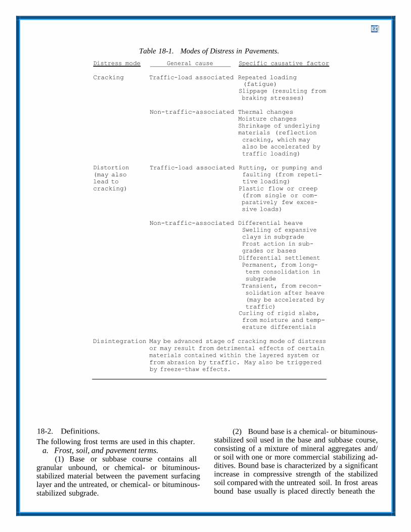
Table 18-1. Modes of Distress in Pavements.
Distress mode General cause Specific causative factor
Cracking Traffic-load associated Repeated loading
(fatigue) Slippage (resulting from braking stresses)
Non-traffic-associated Thermal changes
Moisture changes
Shrinkage of underlying
materials (reflection
cracking, which may
also be accelerated by
traffic loading)
Distortion
(may also
lead to
cracking)
Traffic-load associated Rutting, or pumping and
faulting (from repeti
tive loading)
Plastic flow or creep
(from single or com
paratively few exces
sive loads)
Non-traffic-associated Differential heave
Swelling of expansive
clays in subgrade
Frost action in sub
grades or bases
Differential settlement
Permanent, from long
term consolidation in
subgrade
Transient, from recon
solidation after heave
(may be accelerated by
traffic)
Curling of rigid slabs, from moisture and temp erature differentials
Disintegration May be advanced stage of cracking mode of distress
or may result from detrimental effects of certain
materials contained within the layered system or
from abrasion by traffic. May also be triggered
by freeze-thaw effects.
18-2. Definitions.
The following frost terms are used in this chapter.
a. Frost, soil, and pavement terms.(1) Base or subbase course contains all
granular unbound, or chemical- or bituminous stabilized material between the pavement surfacing layer and the untreated, or chemical- or bituminous stabilized subgrade.
(2) Bound base is a chemical- or bituminous stabilized soil used in the base and subbase course, consisting of a mixture of mineral aggregates and/ or soil with one or more commercial stabilizing ad ditives. Bound base is characterized by a significant increase in compressive strength of the stabilized soil compared with the untreated soil. In frost areas bound base usually is placed directly beneath the
pavement surfacing layer where its high strength and low deformability make possible a reduction in the required thickness of the pavement surfacing layer or the total thickness of pavement and base, or both. If the stabilizing additive is portland cement, lime, or lime-cement-flyash (LCF), the term bound base is applicable only if the mixture meets the requirements for cement-stabilized, lime-stabilized, or LCF-stabilized soil set forth herein and in TM 5- 822-4.
(3) Boulder heave is the progressive upward migration of a large stone present within the frost zone in a frost-susceptible subgrade or base course. This is caused by adhesion of the stone to the frozen soil surrounding it while the frozen soil is under-going frost heave; the stone will be kept from an equal, subsequent subsidence by soil that will have tumbled into the cavity formed beneath the stone. Boulders heaved toward the surface cause extreme pavement roughness and may eventually break through the surface, necessitating repair or reconstruction.
(4) Cumulative damage is the process by which each application of traffic load or each cycle of climatic change produces a certain irreversible damage to the pavement. When this is added to previous damage, the pavement deteriorates con- tinuously under successive load applications or cli- matic cycles.
(5) Frost action is a general term for freezing and thawing of moisture in materials and the re- sultant effects on these materials and on structures of which they are a part, or with which they are in contact.
(6) Frost boil is the breaking of a small section of a highway or airfield pavement under traffic with ejection of soft, semi-liquid subgrade soil. This is caused by the melting of the segregated ice formed by the frost action. This type of failure is limited to pavements with extreme deficiencies of total thickness of pavement and base over frost- susceptible subgrades, or pavements having a highly frost-susceptible base course.
(7) Frost heave is the raising of a surface due to formation of ice in the underlying soil.
(8) Frost-melting period is an interval of the year when the ice in base, subbase, or subgrade materials is returning to a liquid state. It ends when all the ice in the ground has melted or when freezing is resumed. In some cases there may he only one frost-melting period, beginning during the general rise of air temperatures in the spring, but one or more significant frost-melting intervals often occur during a winter season.
(9) Frost-susceptible soil is soil in which significant detrimental ice segregation will occur when the requisite moisture and freezing conditions are present.
(10) Granular unbound base course is base course containing no agents that impart higher co- hesion by cementing action. Mixtures of granular soil with portland cement, lime, or flyash, in which the chemical agents have merely altered certain properties of the soil such as plasticity and gradation without imparting significant strength increase, also are classified as granular unbound base. However, these must meet the requirements for cement-modified, lime-modified, or LCF-modi- fled soil set forth in TM 5-822-4 and in this chap- ter, and they must also meet the base course com- position requirements set forth below.
(11) Ice segregation is the growth of ice as distinct lenses, layers, veins and masses in soils, commonly but not always oriented normal to the di- rection of heat loss.
(12) Nonfrost-susceptible materials are cohe- sionless materials such as crushed rock, gravel, sand, slag, and cinders that do not experience sig- nificant detrimental ice segregation under normal freezing conditions. Nonfrost-susceptible materials also include cemented or otherwise stabilized ma- terials that do not evidence detrimental ice segre- gation, loss of strength upon thawing, or freeze- thaw degradation.
(13) Pavement pumping is the ejection of water and soil through joints, cracks, and along edges of pavements caused by downward move- ments of sections of the pavement. This is actuated by the passage of heavy axle loads over the pave- ment after free water has accumulated beneath it.
(14) Period of weakening is an interval of the year that starts at the beginning of a frost-melting period and ends when the subgrade strength has returned to normal summer values, or when the subgrade has again become frozen.
b. Temperature terms. (1) Average daily temperature is the
average of the maximum and minimum temperatures for a day, or the average of several temperature readings taken at equal time intervals, generally hourly, during a day.
(2) Mean daily temperature is the mean of the average daily temperatures for a given day in each of several years.
(3) Degree-days are the Fahrenheit degree- days for any given day equal to the difference between the average daily air temperature and 32 degrees Fahrenheit. The degree-days are minus
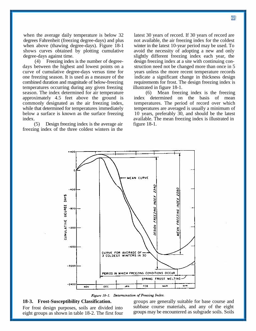
when the average daily temperature is below 32 latest 30 years of record. If 30 years of record are degrees Fahrenheit (freezing degree-days) and plus not available, the air freezing index for the coldest when above (thawing degree-days). Figure 18-1 winter in the latest 10-year period may be used. To shows curves obtained by plotting cumulative avoid the necessity of adopting a new and only degree-days against time. slightly different freezing index each year, the
(4) Freezing index is the number of degree- design freezing index at a site with continuing con- days between the highest and lowest points on a struction need not be changed more than once in 5 curve of cumulative degree-days versus time for years unless the more recent temperature records one freezing season. It is used as a measure of the indicate a significant change in thickness design combined duration and magnitude of below-freezing requirements for frost. The design freezing index is temperatures occurring during any given freezing illustrated in figure 18-1. season. The index determined for air temperature (6) Mean freezing index is the freezing approximately 4.5 feet above the ground is index determined on the basis of mean commonly designated as the air freezing index, temperatures. The period of record over which while that determined for temperatures immediately temperatures are averaged is usually a minimum of below a surface is known as the surface freezing 10 years, preferably 30, and should be the latest index. available. The mean freezing index is illustrated in
(5) Design freezing index is the average air figure 18-1. freezing index of the three coldest winters in the
18-3. Frost-Susceptibility Classification. groups are generally suitable for base course and
For frost design purposes, soils are divided into eight groups as shown in table 18-2. The first four
subbase course materials, and any of the eight groups may be encountered as subgrade soils. Soils

are listed in approximate order of decreasing bear- sity. The order of listing of subgroups under groups ing capacity during periods of thaw. There is also a F3 and F4 does not necessarily indicate the order of tendency for the order of the listing of groups to susceptibility to frost heave of these subgroups. coincide with increasing order of susceptibility to There is some overlapping of frost susceptibility frost heave, although the low coefficients of perme- between groups. Soils in group F4 are of especially ability of most clays restrict their heaving propen- high frost susceptibility.
a. S1 and S2 groups. The S1 group includes soils, they will generally exhibit less frost heave and gravelly soils with very low to medium frost- higher strength after freeze-thaw cycles. susceptibility classifications that are considered b. Fl and F2 groups. The F1 group is intendedsuitable for subbase materials. They will generally to include frost-susceptible gravelly soils that in the exhibit less frost heave and higher strength after normal unfrozen condition have traffic performance freeze-thaw cycles than similar Fl group subgrade characteristics of GM-, GW-GM-, and GP-GM- Soils. The S2 group includes sandy soils with very type materials with the noted percentage of fines. low to medium frost-susceptibility classifications The F. group is intended to include frostsusceptible that are considered suitable for subbase materials. soils that in the normal unfrozen condition have Due to their lower percentages of finer-than-0.02- traffic performance characteristics of GM-, GW- millime- ter grains than similar F2 groups subgrade GM-, GP-GM-, SM-, SW-SM-, or SP- SM-type

materials with fines within the stated limits. base, and subbase to limit the penetration of frost Occasionally, GC or SC materials may occur within into the frost-susceptible subgrade to an acceptable the F. group, although they will normally fall into amount. Included also in this method is a design the F3 category. The basis for division be- tween approach which determines the thickness of pave- the Fl and F. groups is that Fl materials may he ment, base, and subbase necessary to prevent the expected to show higher hearing capacity than F. penetration of frost into the subgrade. Prevention of materials during thaw, even though both may have frost penetration into the subgrade is nearly always experienced equal ice segregation. uneconomical and unnecessary, and will not he used
c. Varved clays. Valved clays consisting of alter- to design pavements to serve conventional traffic, nating layers of silts and clays are likely to combine except when approved by HQUSACE (CEMP-ET) the undesirable properties of both silts and clays. or the appropriate Air Force Major Command. These and other stratified fine-grained sediments b. Reduced subgrade strength method. Themay be hard to classify for frost design. Since such second method does not seek to limit the penetra- soils are likely to heave and soften more readily tion of frost into the subgrade, but it determines the than homogeneous soils with equal average water thickness of pavement, base, and subbase that will contents, the classification of the material of highest adequately carry traffic loads over the design period frost susceptibility should be adopted for design. of years, each of which includes one or more Usually, this will place the overall deposit in the F4 periods during which the subgrade supporting category. capacity is sharply reduced by frost melting. This
d. Special conditions. Under special conditions approach relies on uniform subgrade conditions, the frost group classification adopted for design adequate subgrade preparation techniques, and may be permitted to differ from that obtained by transitions for adequate control of pavement application of the above frost group definitions. roughness resulting from differential frost heave. This will, however, he subject to the specific ap- proval of HQUSACE (CEMP-ET) or the appropri- 18-5. Selection of Design Method. ate Air Force Major Command if the difference is not greater than one frost group number and if complete justification for the variation is presented. Such justification may take into account special conditions of subgrade moisture or soil uniformity, in addition to soil gradation and plasticity, and should include data on performance of existing pavements near those proposed to be constructed.
18-4. Alternative Methods of Thickness Design.
In most cases the choice of the pavement design method will he made in favor of the one that gives the lower cost. Exceptions dictating the choice of the limited subgrade frost penetration method, even at higher cost, include pavements in locations where subgrade soils are so extremely variable (as, for example, in some glaciated areas) that the required subgrade preparation techniques could not be expected to provide sufficient protection against differential frost heave. In other cases special
The thickness design process is the determination of operational demands on the pavement might dictate the required thickness for each layer of a pavement unusually severe restrictions on tolerable pavement system and of the combined thickness of all layers roughness, requiring that subgrade frost penetration above the subgrade. Its objective is determining the he strictly limited or even prevented. If the use of lowest-cost pavement system whose rate of limited subgrade frost penetration method is not deterioration under traffic loads and environmental required, tentative designs must be prepared by conditions will be acceptably low. In seasonal frost both methods for comparison of costs. Also, a areas the thickness design process must include the tentative design must he prepared following the effects of frost action. Two methods are prescribed nonfrost-design criteria, since the thickness for determining the thickness design of a pavement requirements under nonfrost-criteria must be met in that will have adequate resistance to distortion by addition to the frost design requirements. frost heave and cracking and distortion under traffic loads as affected by seasonal variation of supporting 18-6. Limited Subgrade Frost Penetration. capacity, including possible severe weakening during frost-melting periods.
a. Limited subgrade frost penetration method.The first method is directed specifically to the con- trol of pavement distortion caused by frost heave. It requires a sufficient thickness of pavement,
This method of design for seasonal frost conditions should he used where it requires less thickness than the reduced subgrade strength method. Its use is likely to he economical only in regions of low design freezing index.
a. Air freezing index. Air freezing index values
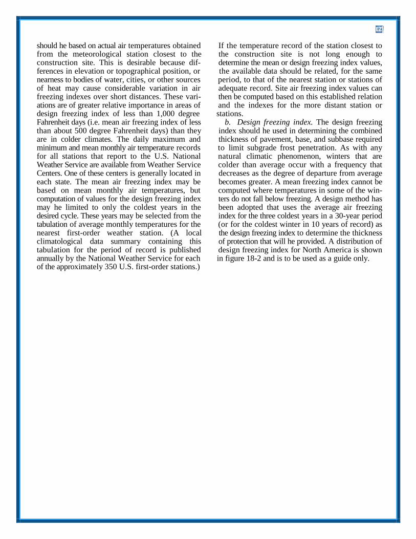
should he based on actual air temperatures obtained If the temperature record of the station closest to from the meteorological station closest to the the construction site is not long enough to construction site. This is desirable because dif- determine the mean or design freezing index values, ferences in elevation or topographical position, or the available data should be related, for the same nearness to bodies of water, cities, or other sources period, to that of the nearest station or stations of of heat may cause considerable variation in air adequate record. Site air freezing index values can freezing indexes over short distances. These vari- then be computed based on this established relation ations are of greater relative importance in areas of and the indexes for the more distant station or design freezing index of less than 1,000 degree stations. Fahrenheit days (i.e. mean air freezing index of less b. Design freezing index. The design freezingthan about 500 degree Fahrenheit days) than they index should he used in determining the combined are in colder climates. The daily maximum and thickness of pavement, base, and subbase required minimum and mean monthly air temperature records to limit subgrade frost penetration. As with any for all stations that report to the U.S. National natural climatic phenomenon, winters that are Weather Service are available from Weather Service colder than average occur with a frequency that Centers. One of these centers is generally located in decreases as the degree of departure from average each state. The mean air freezing index may be becomes greater. A mean freezing index cannot be based on mean monthly air temperatures, but computed where temperatures in some of the win- computation of values for the design freezing index ters do not fall below freezing. A design method has may he limited to only the coldest years in the been adopted that uses the average air freezing desired cycle. These years may be selected from the index for the three coldest years in a 30-year period tabulation of average monthly temperatures for the (or for the coldest winter in 10 years of record) as nearest first-order weather station. (A local the design freezing index to determine the thickness climatological data summary containing this of protection that will he provided. A distribution of tabulation for the period of record is published design freezing index for North America is shown annually by the National Weather Service for each in figure 18-2 and is to be used as a guide only. of the approximately 350 U.S. first-order stations.)

c. Design method. The design method permits a (2) From figure 18-3, determine frost small amount of frost penetration into frost-sus- penetration depth (a). These frost penetration ceptible subgrades for the design freezing index depths are based on modified Berggren formula and year. The procedure is described in the following computational procedures outlined in TM 5-852-6. subparagraphs. Frost penetration depths are measured from
(1) Estimate average moisture contents in pavement surface. Depths are computed on a 12- the base course and subgrade at start of freezing inch rigid pavement kept free of snow and ice, and period, and estimate the dry unit weight of base. are good approximations for bituminous pavements The moisture content of the base is generally af- over 6 to 9 inches of high-quality base. fected by the moisture content of the subgrade, Computations also assume that all soil beneath drainage, precipitation, and depth to water table. As pavements within depths of frost penetration are the base course may, in some cases, comprise granular and non-frost susceptible. It was assumed successive layers containing substantially different in computations that all soil moisture freezes at 32 fine contents, the average moisture content and dry degrees Fahrenheit. Use straight line interpolation unit weight should he weighted in proportion to the where necessary. For rigid pavements greater than thickness of the various layers. Alternatively, if 12 inches thick, deduct 10 degree-days for each layers of bound base course and granular unbound inch of pavement exceeding 12 inches from the base course are used in the pavement, the average design freezing index before entering figure 18-3 to may be assumed to be equal to the moisture content determine frost penetration depth (a). Then add and dry unit weight of the material in the granular extra concrete pavement thickness to the unbound base course. determined frost penetration.

(3) Compute thickness of unbound base C water content of (fig 18-4) required for zero frost penetration into (4) Compute ratio r = subgrade the subgrade as follows: water content of base
C=a-p (5) Enter figure 18-4 with C as the abscissa and, at the applicable value of r, find on the left
where scale the design base thickness b that will result in a=frost penetration depth the allowable subgrade frost penetration s shown on p=thickness of portland cement concrete or bituminous the right scale. If r is greater than 3.0 use 3.0
concrete
9

103
DESIGN FREEZING INDEX (°F - DAYS)
Figure 18-3. Frost Penetration Beneath Pavements. (Sheet 1 of 3)
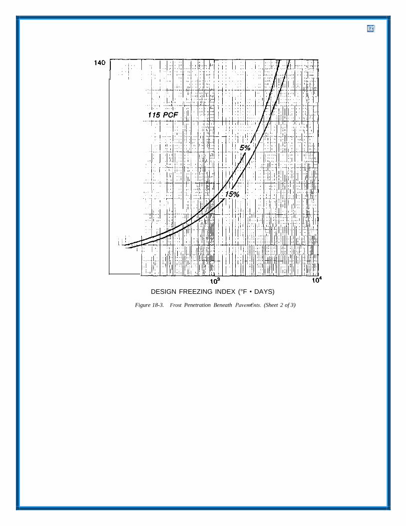
DESIGN FREEZING INDEX (°F • DAYS)
Figure 18-3. Frost Penetration Beneath Pavem€nts. (Sheet 2 of 3)

DESIGN FREEZING INDEX (°F - DAYS)
Figure 18-3. Frost Penetration Beneath Pavements. (Sheet 3 of 3)

d. Thickness. The above procedure will result in layer and of any bound base, as well as the CBR a thickness of material between the frost-susceptible (California Bearing Ratio) requirements of each subgrade and the pavement so that for average field layer of granular unbound base, will be determined conditions subgrade frost penetration of the amount using nonfrost criteria. The thickness of rigid s should not cause excessive differential heave of pavement slab will also be determined from nonfrost the pavement surface during the design freezing criteria. index year.
e. Controlling thickness. If the combined thick- 18-7. Reduced Subgrade Strength. ness of pavement and base required by the non-frost criteria exceeds the thickness given by the limited subgrade frost penetration procedure of design, the greater thickness given by the nonfrost-criteria will be adopted as the design thickness.
f. Effects of nonfrost criteria. The base coursecomposition requirements of this chapter should be rigorously followed. The design base thickness is the total thickness of filter layers, granular unbound base and subbase, and any bound base. For flexible pavements, the thickness of the asphalt surfacing
Thickness design may also be based on the season- ally varying subgrade support that includes sharply reduced values during thawing of soils that have been affected by frost action. Excepting pavement projects that are located in regions of low design freezing index, this design procedure usually requires less thickness of pavement and base than that needed for limited subgrade frost penetration. The method may be used for both flexible and rigid pavements wherever the subgrade is reasonably uniform or can be made reasonably horizontally
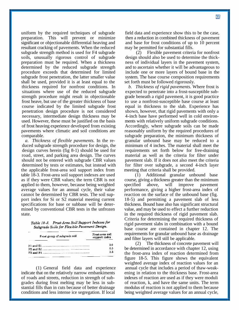
uniform by the required techniques of subgrade field data and experience show this to be the case, preparation. This will prevent or minimize then a reduction in combined thickness of pavement significant or objectionable differential heaving and and base for frost conditions of up to 10 percent resultant cracking of pavements. When the reduced may be permitted for substantial fills. subgrade strength method is used for F4 subgrade (2) Flexible pavement criteria for nonfrost soils, unusually rigorous control of subgrade design should also be used to determine the thick- preparation must be required. When a thickness ness of individual layers in the pavement system, determined by the reduced subgrade strength and to ascertain whether it will be advantageous to procedure exceeds that determined for limited include one or more layers of bound base in the subgrade frost penetration, the latter smaller value system. The base course composition requirements shall be used, provided it is at least equal to the set forth must be followed rigorously. thickness required for nonfrost conditions. In b. Thickness of rigid pavements. Where frost issituations where use of the reduced subgrade expected to penetrate into a frost-susceptible sub- strength procedure might result in objectionable grade beneath a rigid pavement, it is good practice frost heave, but use of the greater thickness of base to use a nonfrost-susceptible base course at least course indicated by the limited subgrade frost equal in thickness to the slab. Experience has penetration design procedure is not considered shown, however, that rigid pavements with only a necessary, intermediate design thickness may be 4-inch base have performed well in cold environ- used. However, these must be justified on the basis ments with relatively uniform subgrade conditions. of frost heaving experience developed from existing Accordingly, where subgrade soils can be made pavements where climatic and soil conditions are reasonably uniform by the required procedures of comparable. subgrade preparation, the minimum thickness of
a. Thickness of flexible pavements. In the re- granular unbound base may be reduced to a duced subgrade strength procedure for design, the minimum of 4 inches. The material shall meet the design curves herein (fig 8-1) should be used for requirements set forth below for free-draining road, street, and parking area design. The curves material as well as the criteria for filter under should not be entered with subgrade CBR values pavement slab. If it does not also meet the criteria determined by tests or estimates, but instead with for filter over subgrade, a second 4-inch layer the applicable frost-area soil support index from meeting that criteria shall be provided. table 18-3. Frost-area soil support indexes are used (1) Additional granular unbound base as if they were CBR values; the term CBR is not course, giving a thickness greater than the minimum applied to them, however, because being weighted specified above, will improve pavement average values for an annual cycle, their value performance, giving a higher frost-area index of cannot be determined by CBR tests. The soil sup- reaction on the surface of the unbound base (fig. port index for Si or S2 material meeting current 18-5) and permitting a pavement slab of less specifications for base or subbase will be deter- thickness. Bound base also has significant structural mined by conventional CBR tests in the unfrozen value, and may be used to effect a further reduction state. in the required thickness of rigid pavement slab.
Criteria for determining the required thickness of rigid pavement slabs in combination with a bound base course are contained in chapter 12. The requirements for granular unbound base as drainage and filter layers will still be applicable.
(2) The thickness of concrete pavement will be determined in accordance with chapter 12, using the frost-area index of reaction determined from figure 18-5. This figure shows the equivalent weighted average index of reaction values for an
(1) General field data and experience annual cycle that includes a period of thaw-weak- indicate that on the relatively narrow embankiments ening in relation to the thickness base. Frost-area of roads and streets, reduction in strength of sub- indexes of reaction are used as if they were moduli grades during frost melting may be less in sub- of reaction, k, and have the same units. The term stantial fills than in cuts because of better drainage modulus of reaction is not applied to them because conditions and less intense ice segregation. If local being weighted average values for an annual cycle,
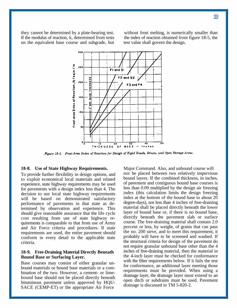
they cannot be determined by a plate-bearing test. without frost melting, is numerically smaller than If the modulus of reaction, k, determined from tests the index of reaction obtained from figure 18-5, the on the equivalent base course and subgrade, but test value shall govern the design.
18-8. Use of State Highway Requirements. Major Command. Also, and unbound course will
To provide further flexibility in design options, and to exploit economical local materials and related experience, state highway requirements may be used for pavements with a design index less than 4. The decision to use local state highway requirements will be based on demonstrated satisfactory performance of pavements in that state as de- termined by observation and experience. This should give reasonable assurance that the life cycle cost resulting from use of state highway re- quirements is comparable to that from use of Army and Air Force criteria and procedures. If state requirements are used, the entire pavement should conform in every detail to the applicable state criteria.
18-9. Free-Draining Material Directly Beneath Bound Base or Surfacing Layer.
Base courses may consist of either granular un- bound materials or bound base materials or a com- bination of the two. However, a cement- or lime- bound base should not be placed directly beneath bituminous pavement unless approved by HQU- SACE (CEMP-ET) or the appropriate Air Force
not be placed between two relatively impervious bound layers. If the combined thickness, in inches, of pavement and contiguous bound base courses is less than 0.09 multiplied by the design air freezing index (this calculation limits the design freezing index at the bottom of the bound base to about 20 degree-days), not less than 4 inches of free-draining material shall be placed directly beneath the lower layer of bound base or, if there is no bound base, directly beneath the pavement slab or surface course. The free-draining material shall contain 2.0 percent or less, by weight, of grains that can pass the no. 200 sieve, and to meet this requirement, it probably will have to be screened and washed. If the structural criteria for design of the pavement do not require granular unbound base other than the 4 inches of free-draining material, then the material in the 4-inch layer must be checked for conformance with the filter requirements below. If it fails the test for conformance, an additional layer meeting those requirements must be provided. When using a drainage layer, the drainage layer must extend to an open ditch or subdrains must be used. Pavement drainage is discussed in TM 5-820-2.

18-10. Other Granular Unbound Base Course.
If the structural criteria for design of the pavement require
more granular unbound base than the 4 inches of free
drainage material, the material shall meet the applicable
requirements of current guide specifications for base of
subbase materials. In addition, the top 50 percent of the
total thickness of granular unbound base must be nonfrost
susceptible and must contain not more than 5 percent by
weight of particles passing the no. 200 sieve. The lower 50
percent of the total thickness of granular unbound base may
be either nonfrostsusceptible material, SI material, or S2
material. If the subgrade soil is SI or S2 material meeting
the requirements of current guide specifications for base or
subbase, the lower 50 percent of granular base will be
omitted. An additional requirement, if subgrade freezing
will occur, is that the bottom 4-inch layer in contact with
the subgrade must meet the filter requirements, or a
geotextile meeting the filter requirements must be placed in
contact with the subgrade. The dimensions and permeability
of the base should satisfy the base course drainage criteria
given in TM 5-820-2/AFM 88-5, Chap 2, as well as the
thickness requirements for frost design. Thicknesses
indicated by frost criteria should be increased, if necessary,
to meet subsurface drainage criteria. Base course materials
of borderline quality should be tested frequently after
compaction to ensure that the materials meet these design
criteria. When placed and compacted, subbase and base
materials must meet the applicable compaction
requirements.
18-11. Use of Fl and F2 Soils for Base Materials.
An alternative to the use of SI and S2 base materials is
permitted for roads and vehicle parking areas. Materials of
frost groups Fl and F2 may be used in the lower part of the
base over F3 and F4 subgrade soils. Fl materials may be
used in the lower part of the base over F2 subgrades. The
thickness of F2 base material should not exceed the
difference between the reduced-subgradestrength thickness
requirements over F3 and F2 subgrades. The thickness of Fl
base should not exceed the difference between the thickness
requirements over F2 and Fl subgrades. Any Fl or F2
material used in the base must meet the applicable
requirements of the guide specifications for base or subbase
materials. The thickness of Fl and F2 materials and the
thickness of pavement and base above the Fl and F2
materials must meet the nonfrost criteria.
18-12. Filter or Drainage Requirements.
For pavements under which subgrade freezing will occur, a
filter or drainage layer meeting the requirements of TM 5-
820-2/AFM 88-5, Chap 2 will be provided.
18-13. Stabilizers and Stabilized Layers.
a. Additives. Asphalt, portland cement, lime, and LCF are
the most common additives used in stabilized soils. Other
stabilizers may be used for pavement construction in frost
areas only with the approval of HQUSACE (CEMP-ET) or
the appropriate Air Force Major Command, as applicable.
The limitations of use, the basic requirements for mixture
design, and the stabilization procedures using bituminous
and chemical stabilizers are set forth in TM 5-822-4.
b. Limitations of use. In frost areas, stabilized soil in most
cases will be used only in a layer or layers making up one
of the upper elements of a pavement system and only when
using the reduced subgrade strength method. Usually, it will
be placed directly beneath the pavement surfacing layer,
where the added cost of stabilization is compensated for by
its structural advantage in effecting a reduction in the
required thickness of the pavement system. However, a
cement, lime, or LCF-stabilized base should not be placed
directly beneath bituminous pavements because cracking
and faulting will be significantly increased. Treatment with
a lower degree of chemical stabilization in layers placed at
lower levels within the pavement system should be used in
frost areas only with caution and after intensive tests. This
is because weakly cemented material usually has less
capacity to endure repeated freezing and thawing without
degradation than firmly cemented material.
c. Construction cut-off dates. For materials stabilized with
cement, lime, or LCF whose strength increases with length
of curing time, it is essential that the stabilized layer be
constructed sufficiently early in the season to allow
development of adequate strength before the first freezing
cycle begins. Research has shown that the rate of strength
gain is substantially lower at 50 degree Fahrenheit than at
70 or 80 degree Fahrenheit. Accordingly, in frost areas it is
not always enough to protect the mixture from freezing
during a 7 day curing period as required by the applicable
guide specifications. A construction cut-off date well in
advance of the onset of freezing may be essential.
18-14. Stabilization with Lime and with LCF. frost areas. However, in addition to the procedures
a. Bound base. Soils containing only lime as thestabilizer are generally unsuitable for use as base course layers in the upper layers of pavement sys- tems in frost areas. Lime, cement, and a pozzolanic material such as flyash may be used in some cases to produce a cemented material of high quality that is suitable for upper base course and that has adequate durability and resistance to freeze-thaw action. In frost areas, LCF mixture design will be based on the procedures set forth in TM 5-822-4 with the additional requirement that the mixture, after freeze-thaw testing as set forth below, should meet the weight-loss criteria specified in TM 5-822- 4 for cement-stabilized soil. The procedures in ASTM D 560 should be followed for freeze-thaw testing, except that the specimens should be com- pacted in a 6-inch diameter mold in five layers with a 10-pound hammer having an 18-inch drop, and that the preparation and curing of the specimens
for mixture design specified in TM 5-822-4, cured specimens of cement-modified soil should be sub- jected to the 12 freeze-thaw cycles in ASTM D 560 (but omitting wire-brushing) or other applicable freeze-thaw procedures. This should be followed by determination of frost design soil classification by means of standard laboratory freezing tests. The USACECRL in Hanover, NH, has the capability to perform these tests. For cement-modified soil used in the base course, the frost susceptibility, deter- mined after freeze-thaw cycling, should meet the requirements set forth for base course in chapter 5 of this manual. If cement-modified soil is used as subgrade, its frost susceptibility, determined after freeze-thaw cycling, should be used as the basis of the pavement thickness design if the reduced sub- grade design method is applied.
18-16. Stabilization With Bitumen.
should follow the procedures indicated in TM 5- Many different types of soils and aggregates can be 822-4 for unconfined compression tests on lime- successfully stabilized to produce a high-quality stabilized soil. bound base with a variety of types of bituminous
b. Lime-stabilized soil. If it is economical to use material. In frost areas the use of tar as a binder lime-stabilized or lime-modified soil in lower layers should be avoided because of its high temperature of a pavement system, a mixture of adequate dura- susceptibility. Asphalts are affected to a lesser bility and resistance to frost action is still necessary. extent by temperature changes, but a grade of as- In addition to the requirements for mixture design phalt suitable to the prevailing climatic conditions of lime-stabilized and lime-modified subbase and should be selected. Excepting these special condi- subgrade materials set forth in TM 5-822-4, cured tions affecting the suitability of particular types of specimens should be subjected to the 12 freeze- bitumen, the procedures for mixture design set forth thaw cycles in ASTM D 560 (but omitting wire- in TM 5-822-4 and TM 5-822-8 usually will ensure brushing) or other applicable freeze-thaw pro- that the asphalt-stabilized base will have adequate cedures. This should be followed by determination durability and resistance to moisture and freeze- of frost-design soil classification by means of stand- thaw cycles. ard laboratory freezing tests. The USACECRL in Hanover, NH, has the capability to perform these 18-17. Subgrade Requirements. tests. For lime-stabilized or lime-modified soil used in lower layers of the base course, the frost suscep- tibility, determined after freeze-thaw cycling, should meet the requirements set forth for base course in chapter 5 of this manual. If lime-stabilized or lime- modified soil is used as subgrade, its frost susceptibility, determined after freeze-thawing cycling, should be used as the basis of the pavement thickness design if the reduced subgrade strength design method is applied.
18-15. Stabilization with Portland Cement.
It is a basic requirement for all pavements con- structed in frost areas, that subgrades in which freezing will occur, shall be prepared to achieve uniformity of soil conditions by mixing stratified soils, eliminating isolated pockets of soil of higher or lower frost susceptibility, and blending the vari- ous types of soils into a single, relatively homoge- neous mass. It is not intended to eliminate from the subgrade those soils in which detrimental frost action will occur, but to produce a subgrade of uni- form frost susceptibility and thus create conditions tending to make both surface heave and subgrade
Cement-stabilized soil meeting the requirements set thaw-weakening as uniform as possible over the forth in TM 5-822-4, including freeze-thaw effects paved area. In fill sections the least frost-susceptible tested under ASTM D 560, may be used in frost soils shall be placed in the upper portion of the areas as base course or as stabilized sub- grade. subgrade by temporarily stockpiling the better ma- Cement-modified soil conforming with the terials, cross-hauling, and selective grading. If the requirements in TM 5-822-4 also may be used in upper layers of fill contain frost-susceptible soils,

and the completed fill section shall be subjected to material. This may be done by raising the grade by the subgrade preparation procedures required for an amount equal to the depth of subgrade prep- cut sections. In cut sections the subgrade shall be aration that otherwise would be prescribed, or by scarified and excavated to a prescribed depth, and undercutting and replacing the wet fine-grained the excavated material shall be windrowed and subgrade to that same depth. In either case the fill bladed successively until thoroughly blended, then or backfill material may be nonfrost-susceptible relaid and compacted. The depth of subgrade prep- material or frost-susceptible material meeting aration, measured downward from the top of the specified requirements. If the fill or backfill material subgrade, shall be the lesser of 24 inches; two- is frost susceptible, it should be subjected to the thirds of the frost penetration for class A, B, and C same subgrade preparation procedures prescribed roads, streets, and open storage areas or one-half of above. the frost penetration for roads, streets, and open c. Cobbles or boulders. A critical condition re- storage areas of class D, E, and F less the actual quiring the attention of inspection personnel is the combined thickness of pavement, base course, and presence of cobbles or boulders in the subgrades. subbase course. The prepared subgrade must meet All stones larger than about 6 inches in diameter the designated compaction requirements for non- should be removed from fill materials for the full frost areas. The construction inspection personnel depth of frost penetration, either at the source or as should be alert to verify that the processing of the the material is spread in the embankments. Any such subgrade will yield uniform soil conditions large stones exposed during the sub-grade throughout the section. To achieve uniformity in preparation work also must be removed, down to some cases, it will be necessary to remove highly the full depth to which subgrade preparation is frost susceptible soils or soils of low frost suscepti- required. Failure to remove stones or large roots bility. In that case the pockets of soil to be removed can result in increasingly severe pavement should be excavated to the full depth of frost roughness as the stones or roots are heaved gradu- penetration and replaced with material surrounding ally upward toward the pavement surface. They the frost-susceptible soil being removed. eventually break through the surface in extreme
a. Exceptions conditions. Exceptions to the cases, necessitating complete reconstruction. basic requirement for subgrade preparation are sub- d. Changes in soil conditions. Abrupt changes ingrades known to be nonfrost susceptible to the soil conditions must not be permitted. Where the depth prescribed for subgrade preparation and subgrade changes from a cut to a fill section, a known to contain no frost-susceptible layers or wedge of subgrade soil in the cut section with the lenses, as demonstrated and verified by extensive dimensions shown in figure 18-6 should be removed and thorough subsurface investigations and by the and replaced with fill material. Tapered transitions performance of nearby existing pavements. Also, also are needed at culverts beneath paved areas, but fine-grained subgrades containing moisture well in in such cases the transition material should be clean, excess of the optimum for compaction, with no fea- nonfrost-susceptible granular fill. Other under- sible means of drainage nor of otherwise reducing pavement pipes should be similarly treated, and the moisture content, and which consequently it is perforated-pipe underdrains should be constructed. not feasible to scarify and recompact, are also ex- These and any other discontinuities in subgrade ceptions. conditions require the most careful attention of
b. Treatment of wet fine-grained subgrades. If construction inspection personnel, as failure to wet fine-grained subgrades exist at the site, it will enforce strict compliance with the requirements for be necessary to achieve frost protection with fill transitions may result in serious pavement distress.

e. Wet areas. Careful attention should be given 18-18. Other Measures to Reduce Heave. to wet areas in the subgrade, and special drainage measures should be installed as required. The need for such measures arises most frequently in road construction, where it may be necessary to provide intercepting drains to prevent infiltration into the subgrade from higher ground adjacent to the road.
f. Rock excavation. In areas where rock excava- tion is required, the character of the rock and seepage conditions should be considered. In any case, the excavations should be made so that posi- tive transverse drainage is provided, and no pockets are left on the rock surface that will permit ponding of water within the depth of freezing. The irregular groundwater availability created by such conditions may result in markedly irregular heaving under freezing conditions. It may be necessary to fill drainage pockets with lean concrete. At intersections of fills with rock cuts, the tapered transitions mentioned above (fig 18-6) are essential. Rock subgrades where large quantities of seepage are involved should be blanketed with a highly pervious material to permit the escape of water. Frequently, the fractures and joints in the rock contain frost-susceptible soils. These materials should be cleaned out of the joints to the depth of frost penetration and replaced with nonfrost susceptible material. If this is impractical, it may be necessary to remove the rock to the full depth of frost penetration.
g. Rock subgrades. An alternative method oftreatment of rock subgrades, in-place fragmenta- tion, has been used effectively in road construction. Blast holes 3 to 6 feet deep are commonly used. They are spaced suitably for achieving thorough fragmentation of the rock to permit effective drainage of water through the shattered rock and out of the zone of freezing in the subgrade. A ta- pered transition should be provided between the shattered rock cut and the adjacent fill.
Other possible measures to reduce the effects of heave are the use of insulation (appendix D) to control depth of frost penetration and the use of steel reinforcement to improve the continuity of rigid pavements that may become distorted by frost heave. Reinforcement will not reduce heave nor prevent the cracking resulting from it, but it will help to hold cracks tightly closed and thus reduce pumping through these cracks. Transitions between cut and fill and culverts and drains change in character or stratification of subgrade soils. Subgrade preparation and boulder removal should also receive special attention in field construction control.
18-19. Pavement Cracking Associated with Frost Heave.
One of the most detrimental effects of frost action on a pavement is surface distortion as the result of differential frost heave or differential loss of strength. These may also lead to random cracking. Deterioration and spalling of the edges of working cracks are causes of uneven surface conditions and sources of debris. Cracking may be reduced by con- trol of such elements as base composition, uni- formity and thickness, slab dimensions, subbase and subgrade materials, uniformity of subsurface moisture conditions, and, in special situations, by use of reinforcement and by limitation of pavement type. The importance of uniformity cannot be overemphasized. Where unavoidable discontinuities in subgrade conditions exist, gradual transitions are essential.
18-20. Control of Subgrade and Base Course Construction.
Personnel responsible for field control of pavement construction in areas of seasonal freezing should give specific consideration to conditions and mate-

rials that will result in detrimental frost action. The susceptible subgrade soils should be avoided by contract plans and specifications should require the making certain that the subgrade is subgrade preparation work established for nonfrost properly graded and compacted prior to placement areas in this manual in frost areas. They also should of base course, by ensuring that the first layer of provide for special treatments such as removal of base course filters out subgrade fines under traffic, unsuitable materials encountered with sufficient and by eliminating the kneading caused by over- information included to identify those materials and compaction or insufficient thickness of the first specify necessary corrective measures. However, layer of base course. Excessive rutting tends to construction operations quite frequently expose cause mixing of subgrade and base materials. This frost-susceptible conditions at isolated locations of can be greatly minimized by frequent rerouting of a degree and character not revealed by even the material-hauling equipment. most thorough subsurface exploration program. It b. Visual inspection. After completion of eachis essential, therefore, that personnel assigned to layer of base course, a careful visual inspection field construction control be alert to recognize should be made before permitting additional mate- situations that require special treatment, whether or rial placement to ensure that areas with high per- not anticipated by the de- signing agency. They centages of fines are not present. In many instances must also be aware of their responsibility for such these areas may be recognized both by examination recognition. of the materials and by observation of their action
under compaction equipment, particularly when the 18-21. Base Course Construction. materials are wet. The materials in any areas that do
Where the available base course materials are well within the limiting percentages of fine material set forth above, the base course construction control should be in accordance with normal practice. In instances where the material selected for use in the top 50 percent of the total thickness of granular unbound base is borderline with respect to per- centage of fine material passing the no. 200 sieve, or is of borderline frost susceptibility (usually ma- terials having 11/2 to 3 percent of grains finer than 0.02 millimeters by weight), frequent gradation checks should be made to ensure that the materials meet the design criteria. If it is necessary for the contractor to be selective in the pit in order to obtain suitable materials, his operations should be
not meet the requirements of the specifications, which will reflect the requirements of this manual, should be removed and replaced with suitable material. A leveling course of fine-grained material should not be used as a construction expedient to choke open-graded base courses, to establish fine grade, or to prevent overrun of concrete. Since the base course receives high stresses from traffic, this prohibition is essential to minimize weakening during the frost-melting period. Action should be taken to vary the base course thickness so as to provide transition, when this is necessary, to avoid abrupt changes in pavement supporting conditions.
18-22. Compaction.
inspected at the pit. It is more feasible to reject Subgrade, subbase, and base course materials must unsuitable materials at the source when large vol- meet the applicable compaction requirements for umes of base course are being placed. It may be nonfrost materials. desirable to stipulate thorough mixing at the pit and, if necessary, stockpiling, mixing in windrows, and 18-23. Use of Insulation Materials in Pavements. spreading the material in compacted thin lifts in order to ensure uniformity. Complete surface stripping of pits should be enforced to prevent mixing of detrimental fine soil particles or lumps in the base material.
a. Gradation of base course materials. Thegradation of base course materials after compaction should be determined frequently, particularly at the start of the job, to learn whether or not fines are being manufactured in the base under the passage of the compaction equipment. For base course materials exhibiting serious degradation charac- teristics, a test embankment may be needed to study the formation of fines by the proposed compaction process. Mixing of base course materials with frost-
The use of synthetic insulating material within a pavement cross section must have the written ap- proval of HQUSACE (CEMP-ET) or the appropri- ate Air Force Major Command, which can also provide advice and assistance in regard to the structural analysis. Criteria for design of pavements containing insulating layers are contained in appendix D.
18-24. Design Example-Heavily Trafficked Road.
Design flexible and rigid pavement for the following conditions-
a. Class B (rolling terrain within the "built-up area”)
b. Category III
c. Design Index. 4 (from TM 5-822-2/AFM 88- protection. 7, Chap 5) m. Flexible pavement design by reduced
d. Design Freezing Index. 700 degree-days subgrade strength method. From the REDUCED e. Subgrade Material. SUB-GRADE STRENGTH section, the frost-area
Uniform sandy clay, CL soil support index is 3.5, which, from the design Plasticity index, 18 curve (fig 8-1), yields a required combined Frost group, F3 thickness of pavement and base of 20 inches. Since Water content, 20 percent (average) this is less than the 26-inch thickness (2.0 + 24) Normal-period CBR, 10 required by the limited subgrade frost penetration Normal-period modulus of subgrade reaction method, the 20-inch thickness would be used. The
k=200 psi/inch on subgrade and 325 psi/ pavement structure could be composed of 2 inches inch on 22 inches of base course. of AC, 12 inches of crushed gravel (since the
f. Base course material. crushed gravel contains only 1 percent passing the Crushed gravel (GW), normal-period CBR = no.200 sieve, it also serves as the free-draining layer 80, 30 percent passing no.10 sieve, 1 percent directly beneath the pavement), and 6 inches of silty passing no.200 sieve. sand subbase material. Subgrade preparation would
g. Subbase course material. be required to a depth of ½ x 45 - 20 = 2½ inches. Coarse to fine silty sand (SP-SM), normal- n. Rigid pavement design by limited subgradeperiod CBR=20, frost penetration method. From figure 12-1, the re- 11 percent passing no. 200 sieve, 6 percent quired pavement thickness p, based on the normal- finer than 0.02 millimeters, frost classification period k = 325 psi per inch, the concrete flexural 52, meets filter criteria for material in contact strength of 650 psi and the design index of 4, is 5.8 with subgrade. inches (use 6 inch minimum). From figure 18-3, the
h. Average dry unit weight (good quality base combined thickness of pavement and base for zero and subbase). 135 pounds per cubic feet frost penetration is 45 inches, equivalent to that for
i. Average water content after drainage (good the flexible pavement. By use of r = 3 and a quality base and subbase). 5 percent thickness of base for zero frost penetration of 39
j. Highest groundwater. About 4 feet below sur- inches (45-6) in figure 18-3, the required thickness face of subgrade of base b is 22 inches, which would allow about 5.5
k. Concrete flexural strength. 650 psi inches of frost penetration into the subgrade in the 1. Flexible pavement design by limited subgrade design year. No subgrade preparation would be
frost penetration method. From figure 18-3, the required. combined thickness a of pavement and base to pre- o. Rigid pavement design by the reduced sub-vent freezing of the subgrade in the design freezing grade strength method. Since frost heave has not index year is 45 inches. According to criteria in been a major problem, a minimum of 4 inches of the chapter 8, the minimum pavement thickness is 2.5 free-draining base course material could be used, inches over a CBR = 80 base course that must be at plus 4 inches of the subbase that will serve as a filter least 4 inches thick. The base thickness for zero material on the subgrade. For this case (8 inches of frost penetration is 42.5 inches (45-2.5). The ratio base and subbase) the frost-area index of reaction of subgrade to base water content is r = 20/5=4. would be 50 psi per inch (fig. 18-5), requiring a Since this is a highway pavement, the maximum pavement slab 7½ inches thick. Sub- grade allowable r of 3 is used in figure 18-4 to obtain the preparation to a depth of ½ x 45-15½=7.0 inches required thickness of base b of 24 inches, which would be required. would allow about 6 inches of frost penetration into p. Alternative designs. Other designs using stabi- the subgrade in the design year. Subgrade lized layers, including ABC pavements, should be preparation would not be required since the investigated to determine whether they are more combined thickness of pavement and base is more economical than the designs presented above. than one-half the thickness required for complete