passenger wheel set assembly...steve finegan, snc-lavalin rail & transit gavin fraser, ch2m jeff...
TRANSCRIPT

A P T A S T A N D A R D S D E V E L O P M E N T P R O G R A M
STANDARD
American Public Transportation Association
1300 I Street, NW, Suite 1200 East, Washington, DC 20005
APTA PR-M-S-019-17
Published: June 9, 2017
Passenger Rail Equipment Safety
Standards Mechanical Working Group
This document represents a common viewpoint of those parties concerned with its provisions, namely operating/ planning agencies, manufacturers, consultants, engineers and general interest groups. The application of any standards, recommended practices or guidelines contained herein is voluntary. In some cases, federal and/or state regulations govern portions of a transit system’s operations. In those cases, the government regulations take precedence over this standard. The North American Transportation Services Association and its parent organization APTA recognize that for certain applications, the standards or practices, as implemented by individual agencies, may be either more or less restrictive than those given in this document.
© 2017 NATSA and its parent organization. No part of this publication may be reproduced in any form, in an electronic retrieval system or otherwise, without the prior written permission of NATSA.
Passenger Wheel Set Assembly
Abstract: This standard provides the minimum requirements for the assembly of rail vehicle wheel sets. It
also addresses training requirements, safety implications and the technical rationale for certain practices.
Keywords: axle, interference, press fit, wheel, wheel assembly, wheel set geometry
Summary: This document establishes a standard for minimum requirements for passenger wheel set
assembly. It combines industry best practices and establishes limits and ranges on certain parameters
associated with wheel set assembly.
Scope and purpose: This standard shall be used by passenger railroads when performing wheel set assembly
functions. It is to be used in conjunction with the railroads’ internal requirements and original equipment
manufacturer (OEM) recommendations. This standard covers the assembly of wheel set components for use
in passenger rail vehicles operating on mainline railroads, as well as light rail and heavy rail transit vehicles.

© 2017 American Public Transportation Association | ii
Table of Contents
Participants ......................................................................................................................................................... iv Introduction ......................................................................................................................................................... v
1. General ........................................................................................................................................................... 1
2. Nomenclature for axles ................................................................................................................................ 1
3. Nomenclature for wheels ............................................................................................................................. 2
4. Nomenclature for wheel set assemblies ..................................................................................................... 3
5. New axle manufacture and condition ......................................................................................................... 5
6. Secondhand (used) axle condition ............................................................................................................. 5
7. New wheels .................................................................................................................................................... 7
8. Secondhand (used) wheels .......................................................................................................................... 9
9. Wheel mounting forces and interference fits ........................................................................................... 10
10. Bearings ..................................................................................................................................................... 12
11. Axle bearing mounting forces ................................................................................................................. 13
12. Other components .................................................................................................................................... 14
13. Press-fitting ............................................................................................................................................... 14
14. Shrink-fitting .............................................................................................................................................. 15
15. Tapered fits ................................................................................................................................................ 16
16. Quality assurance ..................................................................................................................................... 16
17. Records ...................................................................................................................................................... 16
18. Personnel ................................................................................................................................................... 16
19. Equipment .................................................................................................................................................. 16
20. Assembly lubricants ................................................................................................................................. 16 Related APTA standards ................................................................................................................................... 17 References ......................................................................................................................................................... 17 Definitions......................................................................................................................................................... 17 Abbreviations and acronyms ............................................................................................................................. 20 Summary of document changes ........................................................................................................................ 20 Document history .............................................................................................................................................. 20
List of Figures and Tables
Figure 1 Outboard Bearing Axle (Typical) .................................................... 1 Figure 2 Inboard Bearing Axle (Typical) ...................................................... 2
© 2017 American Public Transportation Association | iii
Figure 3 Wheel Nomenclature ....................................................................... 3 Figure 4 Outboard Bearing Wheel Set Assembly (Typical) .......................... 4 Figure 5 Inboard Bearing Wheel Set Assembly (Typical) ............................. 4 Table 1 Inboard Bearing AAR-Class Axles, Bearing Seat and Wheel Seat
Diameter Limits (inches) ................................................................................ 7 Table 2 Outboard Bearing AAR-Class Axles, Bearing Seat and Wheel Seat
Diameter Limits (inches) ................................................................................ 7 Figure 6 Sketch of Profilometer Used to Measure Surface Parameters ......... 8 Figure 7 Wheel Bore Chamfers ..................................................................... 8 Table 3 Inboard AAR Class Bearing Axles ................................................. 10 Table 4 Outboard AAR Class Bearing Axles .............................................. 10 Table 5 Axles — U.S. Customary Unit Designs.......................................... 10 Table 6 Axles — Metric Designs ................................................................. 11 Table 7 Inboard Bearing Mounting Forces .................................................. 13 Table 8 Outboard Bearing Mounting Forces ............................................... 13 Table 9 Radial and Axial Runouts for Wheels ............................................ 15 Figure 8 Seating Force ................................................................................. 18 Figure 9 Mounting and Spike Forces ........................................................... 19

© 2017 American Public Transportation Association | iv
Participants
The American Public Transportation Association greatly appreciates the contributions of the Wheelset Sub-
Working Group, which provided the primary effort in the drafting of this document.
At the time this standard was completed, the working group included the following members:
Glenn Brandimarte, ORX, Chair
Michael Burshtin, Amtrak
Greg Buzby, SEPTA
David Carter, New Jersey Transit
George Chipko, New Jersey Transit
Jeffrey Gordon, Volpe
John Huzinec, Metro-North Commuter Railroad
Jim Johnson, Metro-North Commuter Railroad
Peter Laprè, Volpe
Robert Lavell, New Jersey Transit
Frank Maldari, MTA Long Island Rail Road
Eloy Martinez, LTK Engineering Services
Dakshire Murthy, New Jersey Transit
John Pearson Jr., LTK Engineering Services
Al Roman, Metro-North Commuter Railroad
Mehrdad Samani, CH2M
At the time this standard was initially completed, the Passenger Rail Equipment Safety Standards
Mechanical Working Group included the following members:
Rex Springston, CH2M, Chair
Allen Bieber, ACB RailTech Services
Brad Black, Virginkar & Associates
Greg Blasco, West Coast Express
Stephen Bonina, WSP | Parsons Brinckerhoff
Glenn Brandimarte, ORX
Tony Brown, MTA of Harris County
Michael Burshtin, Amtrak
Gordon Campbell, Crosslinx Transit Solutions
Kevin Carmody, STV
Steve Chrismer, LTK Engineering Services
John Condrasky, Wabtec
Joshua Coran, Talgo
Brendan Crowley, New York Air Brake
Richard Curtis, Curtis Engineering Consulting
Steven Dedmon, Standard Steel
James Dewberry, Wabtec
Joe Di Liello, VIA Rail Canada
Matthew Dick, ENSCO
Adam Eby, Amtrak
Gary Fairbanks, Federal Railroad Administration
Robert Festa, MTA Long Island Rail Road
Steve Finegan, SNC-Lavalin Rail & Transit
Gavin Fraser, CH2M
Jeff Gordon, American Truck Wash Systems
Jeffrey Gordon, Volpe
Mark Hartong, Federal Railroad Administration
James Herzog, LTK Engineering Services
Kenneth Hesser, LTK Engineering Services
Christopher Holliday, STV
George Hud, LTK Engineering Services
Paul Jamieson, SNC-Lavalin Rail & Transit
John Janiszewski, LTK Engineering Services
Kevin Kesler, Federal Railroad Administration
Peter Klauser, WMATA
Heinz-Peter Kotz, Siemens
Tammy Krause, Amtrak
Pallavi Lal, LTK Engineering Services
Peter Lapre, Volpe
Nicolas Lessard, Bombardier Transportation
Cameron Lonsdale, Standard Steel
Francesco Maldari, MTA Long Island Rail Road
Brian Marquis, Volpe
Eloy Martinez, LTK Engineering Services
Raynald Masse, Agence Métropolitaine de Transport
Robert May, LTK Engineering Services
Ronald Mayville, Simpson Gumpertz & Heger
Richard Mazur, Wabtec
Bryan McLaughlin, New York Air Brake

© 2017 American Public Transportation Association | v
Luke Morscheck, LTK Engineering Services
Allen Nutt, LTK Engineering Services
Chris Nuttall
Paul O’Brien, First Transit
John Pearson, LTK Engineering Services
Martin Petzoldt, Railroad Friction Products
Ian Pirie, STV
Danial Rice, Wabtec
Steven Roman, LTK Engineering Services
Carol Rose, STV
Thomas Rusin, Rusin Consulting
Mehrdad Samani, CH2M
Martin Schroeder, CH2M
Richard Seaton, TDG Transit Design Group
Patrick Sheeran, LTK Engineering Services
Melissa Shurland, Federal Railroad Administration
Mark Stewart, SNC-Lavalin Rail & Transit
Narayana Sundaram, ENSCO
Ali Tajaddini, Federal Railroad Administration
Jeff Thompson, SEPTA
Ronald Truitt, AMTRAK
Brian Whitten, SNC-Lavalin Rail & Transit
Todd Williams, Penn Machine Company
Gregory Yovich, NICTD
Project team
Charles Joseph, American Public Transportation Association
Nathan Leventon, American Public Transportation Association
Louis Sanders, American Public Transportation Association
Introduction
This introduction is not part of APTA PR-M-S-019-17, “Passenger Wheel Set Assembly.”
The purpose of this standard is to provide a standardized method for the assembly of wheel sets used in
modern North American passenger train cars applicable to all rail modes for which specified wheel or bearing
dimensions are provided herein.
This standard is based on specifications for wheel-to-axle assembly developed by the Association of
American Railroads (AAR). Many features from AAR specifications have been included herein by reference.
In addition, new procedures have been introduced specific to passenger rail systems beyond requirements of
AAR. This standard is designed to be universal in its application to passenger systems.
Components of passenger railroad wheel sets are assembled onto axles and are held together by friction of
interference fits that must be sufficiently strong to withstand the forces encountered during service. The
strength of an interference fit is critical to the performance and safety of the wheel set assembly.
Passenger railroads have relied on the AAR Manual of Standards and Recommended Practices, Section G-II,
“Wheels and Axle Shop Manual,” for the assembly of their wheel sets. This manual is published and
maintained by the AAR Wheels, Axles, Bearings and Lubrication Committee.
The manual specifies minimum manufacturing standards related to the press-fit assembly of wheels and
bearings onto axles. Because the AAR is concerned almost exclusively with the operation of freight railroads,
the manual may not sufficiently address press-fit assembly features unique to passenger railroad operations,
including components other than wheels and bearings, such as inboard bearing axles and shrink-fitted
components. AAR may also not sufficiently address variations in passenger car manufacturers’ specifications
or the influence of wheel slip control systems, as examples.
As a result, passenger railroad wheel assembly shops often rely heavily on the judgment of experienced
personnel, which may not be universally applied for best performance, nor developed with contemporary
assembly procedures. Many passenger railroads are also concerned about the retirement of experienced
personnel and the resulting loss of valuable engineering and practical expertise. Newer staff may not be fully
aware of the safety implications of the jobs they are performing, nor of the technical rationale for certain

© 2017 American Public Transportation Association | vi
practices. This could lead to wheel assembly practices evolving over time without the benefit of scientific
bases.
Passenger rail operating agencies must develop and maintain written documentation of their policies, rules,
regulations and procedures to ensure safe and efficient operation of their rail systems. The independent
evolution of wheel set assembly procedures among independent transit authorities could have a detrimental
effect on the safety of passenger rail service and on the cost of providing that service.
This standard uses in part the experiences and best practices of numerous passenger railroad operators, plus
new scientific information, in order to establish a common set of rules for the assembly of passenger car
wheel sets.

APTA PR-M-S-019-17 Passenger Wheel Set Assembly
© 2017 American Public Transportation Association 1
Passenger Wheel Set Assembly
1. General All work must comply with the requirements of this safety standard.
All work must comply with the applicable requirements of the latest issue of the AAR Manual of Standards
and Recommended Practices, Section G-II, “Wheel and Axle Shop Manual,” latest issue where referenced in
this standard. If in conflict, this standard takes precedence.
2. Nomenclature for axles See Figure 1 and Figure 2.
Body: For an outboard bearing axle, the body is the portion of the axle between the wheel seats. The
body of an inboard bearing axle is the portion of the axle between the two bearing shoulders.
Body segment: Any part of the body of an axle onto which no component is fitted.
N-dimension: The distance between the centerlines of the two axle bearings.
O-dimension: The overall length of an axle.
U-dimension: For outboard bearing axles, the distance between the inboard edges of the two axle
bearing fillets. The U-dimension for inboard bearing axles is the distance between the two axle
bearing shoulder faces.
FIGURE 1 Outboard Bearing Axle (Typical)
Key: 1=Bearing seat, 2=Dust guard seat, 3=Wheel seat, 4=Brake disc seat, 5=Body segment, U=Bearing location, N=Bearing centerline, O=Overall length

APTA PR-M-S-019-17 Passenger Wheel Set Assembly
© 2017 American Public Transportation Association 2
FIGURE 2 Inboard Bearing Axle (Typical)
Key: 1=Wheel seat, 2=Bearing seat, 3=Bearing shoulder, 4=Gear unit seat, 5=Ground brush seat, 6=Body, 7=Relief groove, U=Bearing location, N=Bearing centerline, O=Overall length
3. Nomenclature for wheels Back: The side of the wheel that faces inboard when assembled to an axle.
Front: The side of the wheel that faces outboard when assembled to an axle.
Rim: The diametrically outer section of the wheel.
Hub: The diametrically inner section of the wheel.
Wheel plate: The thin portion of the wheel that connects the wheel hub to the wheel rim.
Tread: The two-dimensional outermost curved surface of the wheel rim. The tread is the area of the
wheel that makes contact with the rail.
Bore: The two-dimensional innermost circular surface of the wheel hub. The bore is the area of the
wheel that makes contact with the axle seat onto which it is mounted.
Hub projection: The distance by which the back hub-face projects beyond the back rim face. The
hub projection is referred to as positive when it projects beyond the back rim face and negative when
it projects inward from the back rim face. A negative hub projection may also be referred to as a hub
depression. The hub projection shown in Figure 3 is a positive hub projection.
Gage point: The defined location of the theoretical point of contact between the surface of the wheel
flange and the surface of the rail profile.

APTA PR-M-S-019-17 Passenger Wheel Set Assembly
© 2017 American Public Transportation Association 3
FIGURE 3 Wheel Nomenclature
Key: 1=Rim, 2=Plate, 3=Hub, 4=Flange, 5=Flange throat, 6=Tread, 7=Front rim face, 8=Front rim fillet, 9=Front hub fillet, 10=Front hub face, 11=Back rim face, 12=Back rim fillet, 13=Back hub fillet, 14=Back hub face
4. Nomenclature for wheel set assemblies See Figure 4 and Figure 5.
Wheel gage: The distance, measured parallel to the axle centerline, between the gage points of wheel
flanges on the two wheels assembled to an axle.
Back-to-back: The distance, measured parallel to the axle centerline, between the back rim faces of
two wheels assembled to an axle.

APTA PR-M-S-019-17 Passenger Wheel Set Assembly
© 2017 American Public Transportation Association 4
FIGURE 4 Outboard Bearing Wheel Set Assembly (Typical)
Key: 1=Axle, 2=Bearing, 3=Wheel, 4=Brake Disc, 5=Back-to-back, 6=Wheel gage
FIGURE 5 Inboard Bearing Wheel Set Assembly (Typical)
Key: 1=Axle, 2=Bearing, 3=Wheel, 4=Brake Disc, 5=Gear unit, 6=Back-to-back, 7=Wheel gage
APTA PR-M-S-019-17 Passenger Wheel Set Assembly
© 2017 American Public Transportation Association 5
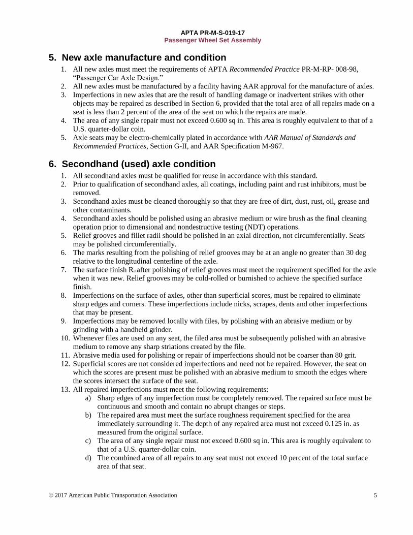
5. New axle manufacture and condition 1. All new axles must meet the requirements of APTA Recommended Practice PR-M-RP- 008-98,
“Passenger Car Axle Design.”
2. All new axles must be manufactured by a facility having AAR approval for the manufacture of axles.
3. Imperfections in new axles that are the result of handling damage or inadvertent strikes with other
objects may be repaired as described in Section 6, provided that the total area of all repairs made on a
seat is less than 2 percent of the area of the seat on which the repairs are made.
4. The area of any single repair must not exceed 0.600 sq in. This area is roughly equivalent to that of a
U.S. quarter-dollar coin.
5. Axle seats may be electro-chemically plated in accordance with AAR Manual of Standards and
Recommended Practices, Section G-II, and AAR Specification M-967.
6. Secondhand (used) axle condition 1. All secondhand axles must be qualified for reuse in accordance with this standard.
2. Prior to qualification of secondhand axles, all coatings, including paint and rust inhibitors, must be
removed.
3. Secondhand axles must be cleaned thoroughly so that they are free of dirt, dust, rust, oil, grease and
other contaminants.
4. Secondhand axles should be polished using an abrasive medium or wire brush as the final cleaning
operation prior to dimensional and nondestructive testing (NDT) operations.
5. Relief grooves and fillet radii should be polished in an axial direction, not circumferentially. Seats
may be polished circumferentially.
6. The marks resulting from the polishing of relief grooves may be at an angle no greater than 30 deg
relative to the longitudinal centerline of the axle.
7. The surface finish Ra after polishing of relief grooves must meet the requirement specified for the axle
when it was new. Relief grooves may be cold-rolled or burnished to achieve the specified surface
finish.
8. Imperfections on the surface of axles, other than superficial scores, must be repaired to eliminate
sharp edges and corners. These imperfections include nicks, scrapes, dents and other imperfections
that may be present.
9. Imperfections may be removed locally with files, by polishing with an abrasive medium or by
grinding with a handheld grinder.
10. Whenever files are used on any seat, the filed area must be subsequently polished with an abrasive
medium to remove any sharp striations created by the file.
11. Abrasive media used for polishing or repair of imperfections should not be coarser than 80 grit.
12. Superficial scores are not considered imperfections and need not be repaired. However, the seat on
which the scores are present must be polished with an abrasive medium to smooth the edges where
the scores intersect the surface of the seat.
13. All repaired imperfections must meet the following requirements:
a) Sharp edges of any imperfection must be completely removed. The repaired surface must be
continuous and smooth and contain no abrupt changes or steps.
b) The repaired area must meet the surface roughness requirement specified for the area
immediately surrounding it. The depth of any repaired area must not exceed 0.125 in. as
measured from the original surface.
c) The area of any single repair must not exceed 0.600 sq in. This area is roughly equivalent to
that of a U.S. quarter-dollar coin.
d) The combined area of all repairs to any seat must not exceed 10 percent of the total surface
area of that seat.
APTA PR-M-S-019-17 Passenger Wheel Set Assembly
© 2017 American Public Transportation Association 6
e) For axle bearing seats, the combined area of repairs to the fitted area of each bearing cone
must not exceed 5 percent of that fitted area.
f) Imperfections may be removed by turning or by machine grinding.
g) Axle areas other than wheel seats that are turned or machine ground must meet the surface
finish requirements for new axles.
h) Axle wheel seats that are turned or machine ground must have a surface finish Ra no greater
than 150 μ-in.
14. Longitudinal scores, including superficial scores and other sharp imperfections at the intersection of
any seat and an adjacent relief groove may not be repaired locally, i.e., using handheld tools. Axles
with this condition must be repaired by machine grinding or by turning.
15. When imperfections are repaired by machine grinding or by turning, the entire seat must be
machined, and any imperfections at the intersection of any seat and an adjacent relief groove must be
completely removed.
16. When imperfections, other than those imperfections at the intersection of any seat and an adjacent
relief groove, are present after machine grinding or turning, those imperfections may be removed
locally as described in this section.
17. A deep-blue hue present on the surface of an axle after it has been cleaned and polished is evidence
that the axle has been overheated. Overheated axles must be scrapped.
18. Axles with evidence of a weld strike or a burn mark from a torch must be scrapped.
19. Axles that are more than 40 years old or that are known to have accumulated more than 10 million
miles of service must be scrapped. Axle age is based on the date the axle was finish machined as
evidenced by the “Y” code and the “Y” date. If there is no “Y” code or date on the axle, then the age
will be based on the date the axle was forged. Axles that show neither of these dates must be
scrapped.
20. The full length of all secondhand axles must be magnetic particle tested (MT) in accordance with
ASTM E1444/E1444M-11, Standard Practice for Magnetic Particle Testing, or with AAR Manual of
Standards and Recommended Practices, Section G-II.
21. Axles with MT flaw indications may be repaired in accordance with this standard. Repaired axles
must be MT retested after any repairs are made.
22. Secondhand axles with MT flaw indications must be scrapped when those flaws cannot be removed.
23. All secondhand axles must be ultrasonic tested in accordance with AAR Manual of Standards and
Recommended Practices, Section G-II. Solid axles must be ultrasonically tested from the outside
diameter of the axle. Hollow axles that have a bore designed for radial testing must be ultrasonically
tested from within the inside of the axle.
24. Inspect all secondhand axle seat diameters prior to mounting components onto those seats.
25. For AAR-class axle designs, the minimum wheel seat and bearing seat diameters must meet the
requirements shown in Table 1 and Table 2. For all other seats onto which components—e.g., brake
discs, gear units, gears or couplings—will be fitted, the limits of acceptability for the diameters of
those seats must be specified by the operator of the vehicle on which the axle is used. When no
acceptability criteria is given, the seat diameters must meet the tolerances specified for new axles.
26. The U-dimension for inboard bearing axles must not be greater than the new axle maximum
specification and not more than 0.030 in. under the new axle minimum specification.
27. The U-dimension for outboard bearing axles must not be greater than the new axle maximum
specification and not more than 0.060 in. under the new axle minimum specification.
28. Axle seats may be electrochemically plated in accordance with AAR Manual of Standards and
Recommended Practices, Section G-II, and AAR Specification M-967.

APTA PR-M-S-019-17 Passenger Wheel Set Assembly
© 2017 American Public Transportation Association 7
TABLE 1 Inboard Bearing AAR-Class Axles, Bearing Seat and Wheel Seat Diameter Limits (inches)
AAR Bearing Class
Bearing Seat (min.)
Bearing Seat (max.)
Wheel Seat (min.)
Wheel Seat Nominal New
Wheel Seat Oversized (max.)
D513 5.1905 5.1615 4.880 5.130 5.180
E563 5.6905 5.6915 5.380 5.630 6.680
F613 6.1905 6.1915 5.880 6.130 6.180
TABLE 2 Outboard Bearing AAR-Class Axles, Bearing Seat and Wheel Seat Diameter Limits (inches)
AAR Bearing Class
Bearing Seat (min.)
Bearing Seat (max.)
Wheel Seat (min.)
Wheel Seat Nominal New
Wheel Seat Oversized (max.)
CC750 5.0030 5.0040 7.250 7.500 7.625
D775 5.1905 5.1915 7.500 7.750 7.875
E825 5.6905 5.6915 8.000 8.250 8.625
F875 6.1905 6.1915 9.750 8.750 8.875
G925 7.003 7.004 9.250 9.500 9.625
7. New wheels 1. At the time of their manufacturing, monobloc steel wheels must be manufactured in accordance with
the latest revision of APTA PR-M-S-012-99, “Manufacture of Wrought Steel Wheels for Passenger
Cars and Locomotives,” or to the latest revision of AAR Specification M-107/M-208, “Wheels,
Carbon Steel.”
2. Wheels must be assembled to axles by press-fitting.
3. Wheels must be bored by turning or machine grinding.
4. Wheels fitted to an axle must be of the same tape size and bear the corresponding tape size marking.
5. Wheel bore finishes must meet the following requirements:
a) Wheel bores must be measured using a suitable instrument with a spatial resolution (cut-off
setting) of 0.030 in.
b) The mean surface roughness Ra must not be greater than 374 μ-in.
c) The peak to valley surface finish, Rz, must not be greater than 1859 μ-in.
d) The mean peak spacing, Rsm must be less than 0.033 in.
e) Figure 6 shows a sketch of a profilometer used to measure surface parameters.

APTA PR-M-S-019-17 Passenger Wheel Set Assembly
© 2017 American Public Transportation Association 8
FIGURE 6 Sketch of Profilometer Used to Measure Surface Parameters
6. Wheel bores must be cylindrical within a limit of 0.002 in.
7. Whenever a taper exists in the bore within the 0.002 in. limit, the taper must be positive; i.e., the
larger diameter must be at the back of the bore and the smaller diameter at the front of the bore.
8. Monobloc wheels must be manufactured from wrought steel.
9. Resilient wheels and tired wheels must be manufactured in accordance with OEM requirements.
10. For wheel bores, the combination of variations in out-of-round and taper must be less than or equal to
0.002 in.
11. Wheels must have a chamfer or radius at the back of the bore to facilitate press-fitting of the wheel.
The requirements for these lead chamfers and radii are shown in Figure 7.
12. Any sharp edge at the front of the wheel bore must be broken after the bore has been machined.
13. Wheels must achieve the mounting forces specified in Section 9.
FIGURE 7 Wheel Bore Chamfers

APTA PR-M-S-019-17 Passenger Wheel Set Assembly
© 2017 American Public Transportation Association 9
8. Secondhand (used) wheels 1. Secondhand wheels need not be bored prior to assembly, provided that they meet the other
requirements of Section 7. Secondhand wheels that are not bored prior to assembly must meet all the
additional requirements in this section.
2. All secondhand wheel bores must be qualified for reuse in accordance with this standard.
3. Secondhand wheels mounted to the same axle must be within one tape size of one another.
4. Secondhand wheel bores must be cleaned thoroughly so that they are free of dirt, dust, rust, oil, grease
and other contaminants.
5. Secondhand wheel bores must meet the requirements for surface finish specified in Section 7.
6. The bores of secondhand wheels must be polished with an abrasive medium or wire brush prior to
dimensional inspection.
7. Imperfections on the surface of bores, other than superficial scores, must be repaired to eliminate
sharp edges and corners. These imperfections include nicks, scrapes, dents and other imperfections
that may be present.
8. Imperfections may be removed locally with files, by polishing with an abrasive medium or by
grinding with a handheld grinder.
9. Whenever files are used on any bore, the filed area must be subsequently polished with an abrasive
medium to remove any sharp striations created by the file.
10. Abrasive cloths used for polishing or repair of imperfections should not be coarser than 80 grit.
11. Superficial scores are not considered imperfections and need not be repaired. However, the bore on
which the scores are present must be polished with an abrasive medium to smooth the edges where
the scores intersect the surface of the bore.
12. All repaired imperfections must meet the following requirements:
a) Sharp edges of any imperfection must be completely removed. The repaired surface must be
continuous and smooth and contain no abrupt changes or steps.
b) Repaired areas must meet the surface roughness requirements of Section 7, Item 5.
c) The depth of any repaired area must not exceed 0.120 in. as measured from the original
surface.
d) The area of any single repair must not exceed 0.600 sq in. This area is roughly equivalent to
that of a U.S. quarter-dollar coin.
e) The combined area of all repairs to any seat must not exceed 10 percent of the total surface
area of that seat.
f) Imperfections may be removed by turning or by machine grinding.
g) Bores that are turned or machine ground must meet the surface finish requirements for new
wheels.
13. Longitudinal scores, including superficial scores and other sharp imperfections in the bore that extend
to the front or back hub face, may not be repaired locally, i.e., using handheld tools. Bores with this
condition must be repaired by machine grinding or by turning.
14. When imperfections are repaired by machine grinding or by turning, the entire bore must be
machined, and any imperfections in the bore that extend to the front or back hub face must be
completely removed.
15. When imperfections, other than those imperfections described in Item 12, are present after machine
grinding or turning, those imperfections may be removed locally as described in this section.
16. Evidence of a deep-blue hue present on the surface of a wheel indicates that the wheel has been
overheated. Overheated wheels must be scrapped.
17. Wheels with evidence of a weld strike or a burn mark from a gas or arc torch must be scrapped.
18. Wheel bores must have the interference fit specified in Section 9 relative to the seat onto which they
will be mounted.
19. Wheels must achieve the mounting forces specified in Section 9.

APTA PR-M-S-019-17 Passenger Wheel Set Assembly
© 2017 American Public Transportation Association 10
9. Wheel mounting forces and interference fits Table 3 specifies the mounting forces and interference fits for wheels mounted on AAR-class inboard axles
when those axles have nominal new wheel seat diameters as shown in the table.
TABLE 3 Inboard AAR Class Bearing Axles
AAR Bearing Class Axle
Bearing Seat Diameter (in.)
Wheel Seat Diameter (in.)
Int. Min. (0.0001 in.)
Int. Max. (0.0001 in.)
Force Min. (U.S. short ton)
Force Max. (U.S. short ton)
D513 5.1915 5.130 45 82 54 91
E563 5.6915 5.630 50 89 60 102
F613 6.1915 6.130 55 97 65 110
K613 6.1915 6.130 55 97 65 110
Table 4 specifies the mounting forces and interference fits for wheels mounted on AAR-class outboard axles
when those axles have the nominal new wheel seat diameters shown in the table.
TABLE 4 Outboard AAR Class Bearing Axles
AAR Bearing Class Axle
Bearing Seat Diameter (in.)
Wheel Seat Diameter (in.)
Int. Min. (0.0001 in.)
Int. Max. (0.0001 in.)
Force Min. (U.S. short ton)
Force Max. (U.S. short ton)
CC750 5.0040 7.500 118 67 80 136
D775 5.1915 7.750 121 70 83 141
E825 5.6915 8.250 129 74 88 149
F875 6.1915 8.750 136 79 94 159
K875 6.1915 8.750 136 79 94 159
G925 7.0040 9.250 144 84 99 168
For axles not included in Table 3 or Table 4, use the mounting forces and interference fits shown in Table 5
for axles designed in U.S. customary units and dimensions.
TABLE 5 Axles — U.S. Customary Unit Designs
Inch Class Axle
Wheel Seat Min. (in.)
Wheel Seat Max. (in.)
Int. Min. (0.0001 in.)
Int. Max. (0.0001 in.)
Force Min. (U.S. short ton)
Force Max. (U.S. short ton)
500 4.750 5.000 44 80 53 90
525 5.000 5.250 47 84 55 93
550 5.250 5.500 49 88 58 98
575 5.500 5.750 51 91 61 103
600 5.750 6.000 53 95 64 108
625 6.000 6.250 56 99 66 112
650 6.000 6.500 58 103 69 117

APTA PR-M-S-019-17 Passenger Wheel Set Assembly
© 2017 American Public Transportation Association 11
TABLE 5 Axles — U.S. Customary Unit Designs
Inch Class Axle
Wheel Seat Min. (in.)
Wheel Seat Max. (in.)
Int. Min. (0.0001 in.)
Int. Max. (0.0001 in.)
Force Min. (U.S. short ton)
Force Max. (U.S. short ton)
675 6.500 6.750 60 106 72 122
700 6.750 7.000 63 110 75 127
725 7.000 7.250 65 114 77 130
750 7.250 7.500 67 118 80 136
775 7.500 7.750 70 121 83 141
800 7.750 8.000 72 125 86 146
825 8.000 8.250 74 129 88 149
850 8.250 8.500 77 133 91 154
875 8.500 8.750 79 136 94 159
900 8.750 9.000 81 140 97 164
925 9.000 9.250 84 144 99 168
950 9.250 9.500 86 148 102 173
975 9.500 9.750 88 151 105 178
1000 9.750 10.000 91 155 108 183
Use the mounting forces and interference fits shown in Table 6 for axles designed in metric dimensions.
TABLE 6 Axles — Metric Designs
Class (mm)
Seat Min. (mm)
Seat Max. (mm.)
Int. Min. (mm)
Int. Max. (mm)
Force Min. (U.S. short ton)
Force Max. (U.S. short ton)
100 94 100 0.087 0.163 41 69
106 100 106 0.093 0.172 44 74
112 106 112 0.099 0.181 46 78
118 112 118 0.104 0.190 49 83
124 118 124 0.110 0.199 52 88
130 124 130 0.115 0.208 54 91
136 130 136 0.121 0.217 57 96
142 136 142 0.126 0.226 59 100
148 142 148 0.132 0.235 62 105
154 148 154 0.138 0.244 65 110
160 154 160 0.143 0.253 67 113
166 160 166 0.149 0.262 70 119
172 166 172 0.154 0.271 72 122
178 172 178 0.160 0.280 75 127

APTA PR-M-S-019-17 Passenger Wheel Set Assembly
© 2017 American Public Transportation Association 12
TABLE 6 Axles — Metric Designs
Class (mm)
Seat Min. (mm)
Seat Max. (mm.)
Int. Min. (mm)
Int. Max. (mm)
Force Min. (U.S. short ton)
Force Max. (U.S. short ton)
184 178 184 0.166 0.289 78 132
190 184 190 0.171 0.298 80 136
196 190 196 0.177 0.307 83 141
202 196 202 0.182 0.316 85 144
208 202 208 0.188 0.325 88 149
214 208 214 0.193 0.334 91 154
220 214 220 0.199 0.343 93 158
226 220 226 0.205 0.352 96 163
232 226 232 0.210 0.361 98 166
238 232 238 0.216 0.370 101 171
244 238 244 0.221 0.379 104 176
250 244 250 0.227 0.388 106 180
Forces are expressed in units of short tons in all four tables.
Diameters are expressed in inches in Table 3, Table 4 and Table 5 and in millimeters in Table 6.
Interferences are expressed in 0.0001 in. in Table 1, Table 2 and Table 3 and in millimeters in Table 4.
Table 3, Table 4 and Table 5 apply to wheel seats where the fitted length of the wheel bore on the seat is
between 5.50 and 7.00 in.
Table 6 applies to wheel seats where the fitted length of the wheel bore on the seat is between 135 and
175 mm.
For all tables, in each row of the table, for wheel seat diameters greater than the diameter shown in the “Seat
Min.” column and less than or equal to the diameter shown in the “Seat Max.” column, wheels must have an
interference fit between the values shown in the “Int. Min.” and “Int. Max.” columns. Wheels must achieve a
mounting force between the “Force Min.” and “Force Max.” values.
10. Bearings 1. Axle bearings must be manufactured in accordance with APTA Recommended Practice APTA PR-
M-RP-008-98, “Passenger Car Axle Design,” published in March 1999, or AAR Standard M-934,
“Freight Car Journal Roller Bearings,” as applicable.
2. Outboard and inboard wheel bearings that are press-fitted onto axles must meet the mounting forces
and seating forces/spike forces specified in Section 11.
3. Bearings that are shrink-fitted to their seats must be assembled in accordance with the applicable
OEM requirements.

APTA PR-M-S-019-17 Passenger Wheel Set Assembly
© 2017 American Public Transportation Association 13
11. Axle bearing mounting forces AAR-class inboard bearings must achieve the mounting and seating forces shown in Table 7.
TABLE 7 Inboard Bearing Mounting Forces
AAR Bearing Class
Mount Min. (U.S. short ton)
Mount Max. (U.S. short ton)
Seat Min. (U.S. short ton)
Seat Max. (U.S. short ton)
Spike Min. (U.S. short ton)
Spike Max. (U.S. short ton)
D 4 10 20 35 20 35
E 5 12 25 40 25 40
L 5 12 25 40 25 40
F 5 15 35 50 35 50
K 5 15 35 50 35 50
AAR-class outboard bearings must achieve the mounting and seating forces shown in Table 8.
TABLE 8 Outboard Bearing Mounting Forces
AAR Bearing Class
Bearing Seat Diameter (in.)
Mount Min. (U.S. short ton)
Mount Max. (U.S. short ton)
Seating Min. (U.S. short ton)
Seating Max. (U.S. short ton)
D 4.6915 5 15 45 55
E 5.6915 5 20 45 55
L 5.6915 5 20 45 55
F 6.1915 5 25 45 55
K 6.1915 5 25 45 55
G 7.0040 5 25 60 70
GG 6.5040 5 25 60 70
GG 6.8750 5 25 60 70
1. Bearings other than AAR-class bearings must be mounted in accordance with the applicable OEM
requirements.
2. Inboard bearings must be seated against the axle bearing shoulder with the prescribed seating force.
3. Inboard bearings must produce a spike force when pressed against the axle bearing shoulder by the
wheel as the wheel makes contact with the bearing.
4. Outboard bearings must be seated against the bearing seat fillet.
5. Outboard bearing end cap screws must be torqued in multiple stages up to the final torque values
specified by the bearing manufacturer.
a) In the first stage, each end cap screw must be torqued to between 50 and 75 percent of its
final torque value using a star-pattern tightening sequence.
b) Subsequent stages may add additional torque using a star-pattern tightening sequence.
c) In the final tightening stage, each end cap screw must be tightened to the torque value
specified by the bearing manufacturer.

APTA PR-M-S-019-17 Passenger Wheel Set Assembly
© 2017 American Public Transportation Association 14
d) For outboard bearings that use a cap screw locking device, install the locking device as
required by the bearing manufacturer. Mark locking plates as specified in AAR Manual of
Standards and Recommendations, Section G-II.
12. Other components Components other than wheels and bearings shall be assembled in accordance with the applicable OEM
requirements.
13. Press-fitting 1. Immediately prior to assembly, both the components and the axles onto which they are to be
assembled must be fully temperature stabilized to within 5 °C of ambient room temperature or to
within 10 °C of one another.
2. The bores of all press-fitted components, as well as the seats onto which those components will be
fitted, must be clean and free of grease, oil, dirt, dust and other contaminants.
3. Prior to assembly, the bore and seat dimensions of the components being fitted must be measured.
These measurements must be recorded and for the interference fit must be within the tolerances
prescribed by this standard.
4. An approved lubricant from Section 20 must be used at the interface between the two components.
5. The lubricant must be applied to the full length of the bore of the component and to at least the first
half of the seat onto which it will be fitted. The first half of the seat is half the length of the seat
starting at the end at which the component initially makes contact during the press-fitting operation.
6. All press-fitted components must be assembled by applying the mounting force concentrically and
evenly to the hub of the component. For bearings, the inner race or a subcomponent of the bearing in
contact with the bearing’s inner race is equivalent to the hub.
7. The pressing operations must be continuous and cannot be interrupted from the start of the operation
until the component has reached its final location.
8. All displacement versus mounting force data taken from fitting components must be recorded and
preserved using a chart recorder or a data collection system.
a) The recorder data must include the displacement of the fitted component as it is being
mounted and the corresponding force applied.
b) Digital data collection systems must record both the displacement and the corresponding
force at a sampling frequency of at least 25 samples per inch of displacement.
9. Each press-fit recording must contain the following component identification data:
a) serial number of the component
b) type of component, e.g., wheel, brake disc, bearing
c) serial number of the axle onto which the component is assembled
d) time and date of assembly
e) operator identification
10. The maximum mounting force obtained must meet the requirement for the component mounted.
11. The shape of the load pressing plotted data must meet the requirements specified in the AAR Manual
of Standards and Recommended Practices, Section G-II.
12. Components not meeting the prescribed mounting force or chart shape are misfits and must be labeled
immediately as misfits.
13. Misfitted components must be completely removed from the axle onto which they were mounted.
14. Misfitted components may be remounted.
15. Wheels mounted on the same axle must be of the same tape size for new wheels and within one tape
size of one another for secondhand wheels.

APTA PR-M-S-019-17 Passenger Wheel Set Assembly
© 2017 American Public Transportation Association 15
16. The radial circular runout and the axial circular runout for wheels must be measured and recorded
after assembly. The measurements must be taken relative to the axle bearing seats by rotating the
wheel set assembly on mounted bearings or on bearing seats while measuring the runouts.
17. Radial runout must be measured in the direction perpendicular to the longitudinal centerline of the
axle and measured on the tread of the wheel within ½ in. of the taping line.
18. Axial runout must be measured in the direction parallel with the longitudinal centerline of the axle.
19. Axial runout must be measured at either the back rim face, the front rim face or the flange of the
wheel.
20. Radial and axial runouts must meet the requirements of Table 9.
TABLE 9 Radial and Axial Runouts for Wheels
Max. Service Speed (mph) Radial (0.001 in.) Axial (0.001 in.)
85 30 60
125 10 20
160 5 15
200 5 12
21. Axle bearings must be rotated by hand after mounting to ensure that they rotate smoothly and freely.
22. Axle bearings that do not rotate smoothly or freely by hand must be labeled as misfits and must be
dismounted from the axle.
23. The axial play for axle bearings must be measured and recorded after mounting.
24. The axial play for bearings may be measured by hand or by the use of a mechanical device designed
for the purpose.
25. The axial play for bearings must be no greater than 0.020 in. when measured by hand.
26. To measure the bearing play by hand, use the following procedure:
a) Rotate the bearing back and forth through at least one full revolution.
b) With the heels of your hands, apply a strong force evenly at two areas 180 deg apart on the
face of the bearing cup. Apply the force in an axial direction.
c) Using the tips of your fingers, pull the bearing back in the opposite direction.
d) Measure the movement of the bearing.
e) Repeat steps b) through d) at least two more times. The repeatability of the measurements
must be within 0.001 in.
27. Measure and record the back-to-back measurement in at least three equidistant locations or,
alternatively, measure and record the minimum and maximum back-to-back measurements. For
narrow flange wheel profiles, the back-to-back measurement must be between 53.250 and 53.375 in.
14. Shrink-fitting 1. Components other than wheels and AP-style bearings may be assembled to axles by shrink-fitting.
2. Because shrink-fitted components do not have a mounting force chart, it is extremely important that
the dimensions of the bore and the corresponding seat be measured carefully prior to assembly to
ensure that the required interference will be present when the components cool.
3. The diameter of the bore of a shrink-fitted component and the diameter of the seat onto which it is
fitted must be recorded.
4. To facilitate removal, the seat onto which a component will be shrink-fitted may be coated with an
approved lubricant capable of withstanding the heat from the component.
5. Press-fitted components may be used to achieve final positioning of a shrink-fitted component.

APTA PR-M-S-019-17 Passenger Wheel Set Assembly
© 2017 American Public Transportation Association 16
6. For shrink-fitted components that are moved to their final position by contact with press-fitted
components, the length of pressed travel for the shrink-fitted component must be less than or equal to
0.500 in.
15. Tapered fits 1. Taper-fitted components must be mounted in accordance with the applicable OEM requirements.
16. Quality assurance 1. Each wheel set assembly facility shall have a documented quality assurance system and a quality
assurance manual describing that system.
2. The quality system shall meet the requirements of AAR Manual of Standards and Recommended
Practices, Section J, Specification M-1003.
17. Records 1. Data records of all press-fitted components defined in Section 13, Items 7 and 8, plus dimensional
data defined in Section 9, must be maintained for 20 years.
2. The serial numbers of all components of any wheel set assembly processed for maintenance or
overhauling, i.e., any wheel set for which any component is removed, must be recorded.
3. The railroad operating authority shall keep records of all wheel set assemblies applied to any revenue
service vehicle. These records must be maintained for 20 years and include the following information:
a) the vehicle number to which the wheel set assembly is applied
b) the position of the wheel set assembly within the vehicle
c) sufficient information from the wheel set assembly to uniquely identify it
d) the date on which the wheel set assembly was applied to the vehicle
e) records for magnetic particle inspections of axles
18. Personnel 1. Personnel involved in the assembly of wheel sets must demonstrate knowledge and proficiency of the
requirements of this standard as ensured through training certifications provided by the transit
operator or wheel set assembly shop.
19. Equipment 1. All equipment used for the assembly of wheel sets must be accurate and consistently capable of
meeting the requirements of this standard.
2. Press chart and data collection recorders must be accurate within ±1 percent of the maximum reading
recorded for force.
3. Press chart and data collection recorders must be accurate within ±3 percent of the maximum reading
recorded for distance traveled.
20. Assembly lubricants 1. The following lubricants or equivalent may be used for press-fitting operations:
a) all AAR-approved press-fitting lubricants
b) Dow Corning Molycote G-n paste
c) Fuchs-Lubritech Gleitmo 100
2. The following lubricants or equivalent may be used for shrink-fitting:
a) Dow Corning Molycote G-n paste
b) Fuchs-Lubritech Gleitmo

APTA PR-M-S-019-17 Passenger Wheel Set Assembly
© 2017 American Public Transportation Association 17
Related APTA standards
APTA PR-M-RP- 008-98, “Passenger Car Axle Design”
References
Association of American Railroads, Manual of Standards and Recommended Practices, Section G-II, “Wheel
and Axle Shop Manual,” March 2012.
American Society for Testing and Materials:
ASTM E1444, “Standard Practice for Magnetic Particle Examination”
E1444/E1444M-11, “Standard Practice for Magnetic Particle Testing”
ASME B46.1, “Surface Texture (Surface Roughness, Waviness, and Lay)”
Definitions
AAR-class bearing: Bearings manufactured in accordance with the AAR Manual of Standards, Section H,
“Journal Bearings and Lubrication,” for use on bearing seat diameters as described therein.
ambient temperature: The temperature of the local surroundings. Inside a temperature-controlled building,
ambient temperature is the same as room temperature.
AP-style bearing: A roller bearing assembly in which all the components are contained in a single unit. AP
bearings contain two cone assemblies, a spacer ring between the cones to control axial clearance, a one-piece
cup, and lubricant sealing systems at each end of the cup. Also known as an “AP-type” bearing or simply an
“AP” bearing.
component: A part or a subassembly having a unique function within the assembly in which it is
incorporated. Wheels, bearings, gears, gear units, brake discs, transmissions and couplings are components of
wheel set assemblies. A component of a component is a subcomponent.
circular runout: See ASME-Y14.5.
grinding: The removal of metal using a stone wheel or a wheel or disc composed of other materials
specifically designed for the removal of metal. Machine grinding is grinding that uses a machine tool,
appropriately referred to as a grinder. Hand grinding is grinding using a handheld power tool.
interference fit: The difference in diameters between two assembled components where the bore of the fitted
component is smaller than the seat onto which it is fitted.
machining: The removal of metal from a component using a machine tool, specifically by machine grinding
or by turning.
monobloc wheel: A one-piece wheel made from a single piece of steel.
mounting force: The final force achieved during the press-fitting of two components discounting any spike
force. See Figure 5.
new: The condition of a component or assembly that has never operated in service.
press-fitting: The assembly of two components using an interference fit.

APTA PR-M-S-019-17 Passenger Wheel Set Assembly
© 2017 American Public Transportation Association 18
relief groove: A radius undercut between two adjacent seats. The purpose of relief grooves is the reduction of
stress concentrations in the area between two closely sized diameters adjacent to each other.
resilient wheel: A multi-piece wheel in which the tire is separated from the wheel center with resilient
elements.
score: A linear scratch in the surface of a seat running axially along the seat. A superficial score is a score
that is less than 0.002 in. deep.
seat: A cylindrical or conical surface onto which a component is assembled by means of an interference fit,
e.g., wheel seat, bearing seat, brake disc seat.
seating force: The absolute force applied to a component that is mounted against a constraint. See Figure 8.
FIGURE 8 Seating Force
secondhand: A used component or assembly that has operated in service.
short ton (U.S. short ton): 2000 lbs.
spike: The force applied to a press-fitted component after that component has contacted a restraint. The
restraint may be a shoulder, fillet or a previously fitted component that is constrained. The magnitude of the
spike is the difference between the maximum force applied after contacting the constraint and the force
applied immediately before contacting the restraint. See Figure 9.

APTA PR-M-S-019-17 Passenger Wheel Set Assembly
© 2017 American Public Transportation Association 19
FIGURE 9 Mounting and Spike Forces
shrink-fitting: Fitting accomplished by heating or cooling a component to a temperature sufficient to
temporarily create a clearance between the bore of the component and the seat onto which it will be
assembled.
surface finish: The geometric irregularities that define the texture of a surface. All references to surface
finish and the metrics and parameters quantifying the surface finish such as Ra, Rz, etc., are as defined in
ASME B46.1.
tape size: The number of eighths of an inch by which the circumference of the wheel, at the taping line,
exceeds 84 in. Tape sizes are applicable only to wheels.
taping line: The diameter of the wheel at the wheel tread taken from a measurement of wheel circumference
using a tape positioned on the wheel tread at the center of the contact area between wheel tread and top of rail
with the wheel set centered between the rails.
temperature stabilized: A component is temperature stabilized when its entire mass has reached the ambient
temperature of the environment in which it resides.
tire: The rim section of a multi-piece wheel.
tired wheel: A multi-piece wheel that uses a steel tire connected (with or without resilient elements) to a
wheel center. The wheel center may be steel, aluminum or other material.
turning: The removal of material from a part using a cutting tool in a lathe. The removal of material takes
place with a stationary cutting tool in contact with the rotating part.
wheel set assembly: A collection of components fully assembled into a single unit that allows rolling
movement of the rail vehicle to which it is attached.

APTA PR-M-S-019-17 Passenger Wheel Set Assembly
© 2017 American Public Transportation Association 20
Abbreviations and acronyms
AAR Association of American Railroads
ASNT American Society for Nondestructive Testing
ASTM American Society for Testing and Materials
NATSA North American Transportation Services Association
NDT nondestructive testing
MT magnetic particle testing
OEM original equipment manufacturer
Ra mean surface roughness as defined in ASME B46.1-2009
Rsm mean peak spacing as defined in ASME B46.1-2009
Rz peak to valley height as defined in ASME B46.1-2009
UT ultrasonic testing
Summary of document changes
Document history
Document Version
Working Group Vote
Public Comment/ Technical Oversight
CEO Approval Policy & Planning Approval
Publish Date
First published Dec. 15, 2015 Jan. 31, 2017 April 21, 2017 June 8, 2017 June 9, 2017
First revision — — — — —
Second revision — — — — —