particle-in-cell simulation of uniformly loaded w-band gyro-twt to study its multi-mode beam-wave...
TRANSCRIPT

Amit Arora et al., International Journal of Microwaves Applications, 5(5), September - October 2016, 41 – 47
41
ABSTRACT In this paper, the Particle-In-Cell (PIC) simulation of a uniformly loaded, operating in fundamental circular TE01 mode gyrotron Traveling Wave Tube (gyro-TWT) amplifier is studied for its beam-wave interaction behavior for its principle mode along with other possible competitive modes. The uniformly loaded section of RF circuit provides sufficient attenuation to suppress the spurious modes including competitive modes, e.g., TE11, TE21 and TE02 modes. The PIC simulation predicts a peak RF output power of ~ 135 kW at 92 GHz with a saturated power gain of ~ 50 dB and a bandwidth ~ 5%. The electronic efficiency is calculated as ~ 27% for 100 kV, 5A annular electron beam having unity pitch. The performance of the amplifier has been investigated with respect to electrical parameters including beam voltage and current, beam pitch, velocity spread, RF drive power, magnetic field, etc. Key words: Absolute instability, uniform dielectric load, gyro-TWT, millimeter wave amplifier, PIC simulation. 1. INTRODUCTION Gyrotron devices are working on the principle of electron cyclotron resonance maser (ECRM) instability, and generate coherent electromagnetic radiation in both millimeter and sub-millimeter wave regime [1]. The features of gyro-TWT amplifier including high power and broad bandwidth are still making it an attractive source for high resolution radar, high density communication system, tracking of space substance, etc. Gyro-TWT uses a non-resonant RF structure, like, smooth wall cylindrical waveguide as its RF interaction circuit, in which the energetic gyrating electrons interact with transverse electric field of the EM waves under the synchronism condition, i.e. :
0z z ck v s , (1)
where, ω is the angular wave frequency, kz is the axial propagation constant, vz is the electron axial velocity, s is the cyclotron harmonic number and Ωc is the relativistic electron cyclotron frequency given by,
0
0
.ceBm
(2)
Gyro-TWT is often suffered by its local problems including self-start or backward wave oscillations (BWO), reflective oscillations, and mode competition problem due to the small transverse dimension of its RF circuit at millimeter and sub-millimeter wavelength operation. These issues eventually degrade the performance of the amplifier. Over the period of years many novel structures were proposed to suppress the oscillations and ultimately enhancing its efficiency [2]. In NTHU, Tsai et al. have experimentally studied the absolute instability of W-band gyro-TWT operating in TE01 mode at the [3]. In 2004, Song et al. have demonstrated the first experimental W-band, TE01 mode gyro-TWT, which produced ~140kW of RF power with a conversion efficiency of ~28% and a saturated gain ~ 50dB for a 100kV, 5A electron beam with an axial spread of 5% [4]. A single stage second harmonic gyro-TWT using metal fins was designed by Wang et al. and predicted ~ 600kW peak RF output power with a saturated gain of ~ 30dB, efficiency of ~24% and a bandwidth of ~ 3 % for 100kV, 25A beam having the pitch of 1.2 and an axial spread 8% [5]. In 2004, Yeh et al., have proposed a mode selective second harmonic TE02 gyro TWT with a distributed loss and severed structure that predicted 215 kW peak RF output power with an efficiency of ~14 %, saturated gain of 60 dB and a bandwidth of 1.7 GHz for the velocity spread of 5 % at 89.9 GHz [6]. In 2005, Blank et al. developed a W-band gyro-TWT amplifier operating in TE01 mode for 1.5kW peak RF output power with ~ 7 GHz of wide bandwidth [7]. In 2010, Chiu et al, have studied the performance of a W-band gyro-TWT under marginal stability criterion i. e., results demonstrates guidelines for design parameter to achieve maximum power, efficiency or bandwidth [8]. Yan et al. have demonstrated a Q-band gyro-TWT using distributed loss technique for a saturated RF output power 152 kW with a gain of ~ 41dB, conversion efficiency of ~ 22% and a bandwidth of ~ 2GHz [9]. A pulse prototype of W-band TE01 mode gyro-TWT was designed by Du et al. for a peak saturated power ~ 68 kW at 93.2 GHz with a highest efficiency of ~ 32% and the bandwidth of ~ 4 GHz [10]. A W-band gyro-TWT amplifier loaded with a non-uniform periodic lossy dielectric rings operating in fundamental TE01 mode was designed by Yan et al. to produce a peak output power of ~ 112 kW, saturated gain of ~70 dB, bandwidth of ~ 4 GHz and a conversion efficiency of ~23% [11].
Particle-In-Cell Simulation of Uniformly Loaded W-band Gyro-TWT to Study its Multi-Mode Beam-Wave Interaction Behavior
Amit Arora, M. Thottappan, and P. K. Jain Centre of Research in Microwave Tubes, Department of Electronics Engineering, Indian Institute of
Technology (Banaras Hindu University), Varanasi – 221005, INDIA Email: [email protected], [email protected], [email protected]
ISSN 2320 - 2599 Volume 5, No. 5, September – October 2016
International Journal of Microwaves Applications Available Online at http://www.warse.org/IJMA/static/pdf/file/ijma01552016.pdf

Amit Arora et al., International Journal of Microwaves Applications, 5(5), September - October 2016, 41 – 47
42
In general, the 3D beam-wave interaction behavior in vacuum electron beam devices is studied using commercially available electromagnetic codes, including MAGIC using Finite Difference Time Domain (FDTD) technique, CST Particle Studio [18] using Finite Integration Technique (FIT), VSIM, CHIPIC, etc. Using distributed loss technique, Xu et al. demonstrated a Ka-band fundamental mode gyro-TWT for ~100kW peak power with a gain of ~56dB, electronic efficiency of ~24 % and the bandwidth of ~5 % [12]. In 2011, Xu et al. have simulated a Ka-band gyro-TWT amplifier with severed structure operating in the fundamental TE01 mode to study the beam-wave interaction using a PIC code. The simulations predicted an output peak power of ~ 254 kW with 36% efficiency, 25 dB saturated gain at 34.8 GHz for a 70 kV, 10 A electron beam [13]. In 2013, a Ka-band periodically loaded gyro-TWT was simulated using 3D MAGIC PIC code by Alaria et al. The simulation predicted an RF output power of 80kW with saturated gain of 50dB and 3dB bandwidth of ~3GHz [14]. Recently, Wang et al. simulated a ceramic loaded Ku-band gyro-TWT to study the suppression of BWO. Further, it was experimented for 153 kW of saturated power with 41 dB gain, 20% efficiency and 14% bandwidth while driven by a 12A, 63 kV electron beam having the pitch of 1.2 and a spread of 5% [15]. A two stage distributed lossy circuit was studied for a low voltage W-band gyro-TWT by Li et al. using a 3D electromagnetic code “CHIPIC”. It predicted a peak RF power of ~ 42.5 kW with an electronic efficiency of ~ 30% in TE01 mode at 93.8GHz [16]. Further, Tang et al. have investigated a W-band dielectric loaded gyro-TWT and the same was simulated using “CST Particle Studio” code that predicted ~ 198kW of RF power at 92.5GHz with ~62dB saturated gain and an electronic efficiency of ~28% for a 70kV and 10A electron beam [17]. In the present work, a uniformly loaded W-band gyro-TWT amplifier operating in TE01 mode is presented for investigating its beam-wave interaction mechanism. The resistive coating at the inner wall of the RF circuit provides high loss to the spurious modes responsible to originate the BWOs in the absolute region and allow the convective operating mode to grow in it. The rest of the article is organized as follows: the cold dispersion and the optimized electrical and circuit parameters are discussed in Section 2. The modeling of the resistively coated RF interaction circuit and its simulation under cold and hot condition are described in Section 3. The parametric analysis to evaluate the performance of the amplifier is discussed in Section 4 and finally the conclusions are drawn in Section 5. 2. DISPERSION AND DESIGN PARAMETRES The cold dispersion of the W-band conventional gyro-TWT amplifier operating in TE01 mode for the electrical parameters of 100 kV and 5A is shown in Figure 1. The nearby spurious modes including (1)
11TE , (1)21TE , and (2)
02TE that lead to absolute instability are also shown in Figure 1. For higher efficiency and
Figure 1: Dispersion characteristics for the operating (TE01) and possible oscillating (TE11, TE21 and TE02) modes of the gyro-TWT.
Figure 2: Normalized coupling coefficient variations with respect to normalized guiding centre radius of the gyro-TWT.
Figure 3: Cross sectional view the resistively coated RF
interaction circuit for W-band gyro-TWT amplifier. wider bandwidth of the amplifier, the magnetic field is chosen such that the fundamental cyclotron resonance line nearly grazes the TE01 waveguide mode, i. e., B0/Bg= 0.995. To minimize the interception of electrons with wall, reduce dielectric charging and having low coupling of the desired operating mode with spurious modes ( (1)
11TE , (1)21TE , and

Amit Arora et al., International Journal of Microwaves Applications, 5(5), September - October 2016, 41 – 47
43
(2)02TE ), the beam radius is chosen through the coupling
co-efficient plot as shown in Figure 2. The cross sectional view of the uniformly loaded RF interaction circuit with the radius of ‘rw’ and the lossy coating thickness of ‘tc’ at its inner wall is shown in Figure 3. The optimized design parameters of the present W-band gyro-TWT are shown in Table I. 3. PIC SIMULATION 3.1 Simulation Model In the present work, for zero drive stability, the RF interaction circuit has been divided into two sections: uniformly loaded section and unloaded section. The uniformly loaded section length (L1) of 110 mm is a cylindrical waveguide of 2.01 mm radius, which is coated with a lossy material having the resistivity of ρcc = 120.4 x 10⁻³ Ω-cm. The nonlinear unloaded section length (L3) of 25 mm is modeled with an annealed copper having conductivity of σ = 5.8×10⁷ S/m and that is coupled to L1 through a lossy up-taper section length (L2) of 10 mm with a tapering angle of ~ 0.06 degree at 92 GHz as shown in Figure 4. The loaded section, L1 eliminates the most persistent absolute instabilities and the unloaded section, L3 avoids damping, hence provides stronger coupling between electron beam and RF wave and high growth rate. In addition, the lossy up-taper section L2 is used to increase the stability and bandwidth too. The presence of taper section effectively reduces the length of the interaction region which in turn increases the absolute threshold value and stabilizes the output. An axial uniform static magnetic field of 3.56 Tesla decides the coupling strength of the beam-wave interaction. The radius of the cathode is kept equal to the beam radius (rg) of 0.45 times of the RF circuit radius (rw). Further, sixteen annular gyrating beamlets, having the same Larmor radius are considered here in the simulation, to be distributed uniformly in the transverse direction of the RF circuit. The axial velocity spread depends on the quality of DC beam generated by emitter. For simplicity, secondary emission of electrons is neglected and low energy electrons are assumed to be absorbed on the wall of the waveguide. Table 1: Optimized Design Parameters of W-band Uniformly
Loaded Gyro-TWT Amplifier [4]
Particulars Value Beam Voltage, Vb 100 kV Beam Current, Ib 5 A Pitch factor, (α) 1
Velocity spread, (∆vz/vz) 5% Operating mode TE01
Magnetic Field, B0 3.56 T Cutoff frequency, f 91 GHz Circuit radius, rw 2.01 mm
Guiding center radius, rg 0.45rw Wall Resistivity, ρ 70,000 ρcu Lossy length, L1 110 mm
Lossy taper length, L2 10 mm Copper circuit length, L3 25 mm
Figure 4: CST modeled longitudinal view of RF interaction circuit
for the W-band gyro-TWT.
(a) (b)
Figure 5: (a) Contour of electric field pattern (b) Vector plot of electric field pattern inside the heavily loaded gyro-TWT amplifier.
Figure 6: Transmission loss of the desired TE01 mode amd nearby
competing modes (TE11, TE21, and TE02).
The beam-wave interaction phenomenon in a gyro-TWT amplifier is studied using 3D PIC simulation code which has a higher accuracy of calculation than 2D simulation code. In the present work, a commercial 3D PIC simulation code based on Finite Integration Technique (FIT) is preferred that uses an appropriate hexahedral/tetrahedral meshing technique to calculate beam-wave interaction behavior. In the present simulation, the number of Cells per wavelength is chosen as 10 with largest cell size is 0.318987 and the smallest cell size is 0.029 that results a total of 3,153, 856 cells in the interaction region of interest. The space charge effects on electron beam and interruption of mode distribution induced by electron beam have been neglected. The tangential component of the electric field has been set as zero (i. e., Et = 0) in all directions along the boundary of the RF circuit. For observing the operation of amplifier in the desired mode and at desired frequency, field monitors are set. The PIC phase space monitors are used for observing the energy transfer mechanism between the electron beam and the EM waves and also bunching of the electrons. The simulation results generally give the temporal growth of fields of various modes in time domain and their Fourier transform (FT) gives the frequency of operation of the respective modes.
Amit Arora et al., International Journal of Microwaves Applications, 5(5), September - October 2016, 41 – 47
44
3.2 Results and Discussion
A. Cold Simulation To ensure the device operation in the desired mode and frequency band, the cold or beam absent simulation is performed with the help of Eigenmode solver. The solver confined the desired TE01 mode inside the structure and that is propagating along the direction of propagation. Figure 5 (a) shows the contour of electric field pattern of the desired TE01 mode and Figure 5 (b) shows the corresponding vector plot in the uniformly coated waveguide. Further, the transmission loss for the desired and its nearby spurious modes are calculated using transient solver. The uniformly coated lossy two port section, L1 was cold simulated for it scattering parameters as shown in Figure 6. It shows that the spurious modes, including (1)
11TE , (1)21TE , and (2)
02TE modes having the transmission loss of ~ 17.2 dB/cm, ~ 17.8 dB /cm, and ~ 5 dB/cm at ~ 68.35GHz, ~ 76.61GHz, and ~ 166.67GHz, respectively. However, the desired operating TE01 mode is attenuated by ~ 4.7 dB /cm at the desired operating frequency of ~ 92 GHz. This ensures that lossy material coated inside the RF circuit having the resistivity of 120.4 x 10⁻³ Ω-cm is good enough to support the desired TE01 mode and suppress other nearby spurious modes.
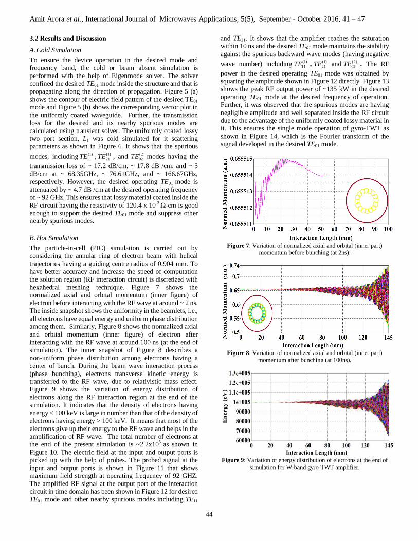
B. Hot Simulation The particle-in-cell (PIC) simulation is carried out by considering the annular ring of electron beam with helical trajectories having a guiding centre radius of 0.904 mm. To have better accuracy and increase the speed of computation the solution region (RF interaction circuit) is discretized with hexahedral meshing technique. Figure 7 shows the normalized axial and orbital momentum (inner figure) of electron before interacting with the RF wave at around ~ 2 ns. The inside snapshot shows the uniformity in the beamlets, i.e., all electrons have equal energy and uniform phase distribution among them. Similarly, Figure 8 shows the normalized axial and orbital momentum (inner figure) of electron after interacting with the RF wave at around 100 ns (at the end of simulation). The inner snapshot of Figure 8 describes a non-uniform phase distribution among electrons having a center of bunch. During the beam wave interaction process (phase bunching), electrons transverse kinetic energy is transferred to the RF wave, due to relativistic mass effect. Figure 9 shows the variation of energy distribution of electrons along the RF interaction region at the end of the simulation. It indicates that the density of electrons having energy < 100 keV is large in number than that of the density of electrons having energy > 100 keV. It means that most of the electrons give up their energy to the RF wave and helps in the amplification of RF wave. The total number of electrons at the end of the present simulation is ~2.2x10⁵ as shown in Figure 10. The electric field at the input and output ports is picked up with the help of probes. The probed signal at the input and output ports is shown in Figure 11 that shows maximum field strength at operating frequency of 92 GHZ. The amplified RF signal at the output port of the interaction circuit in time domain has been shown in Figure 12 for desired TE01 mode and other nearby spurious modes including TE11
and TE21. It shows that the amplifier reaches the saturation within 10 ns and the desired TE01 mode maintains the stability against the spurious backward wave modes (having negative wave number) including (1)
11TE , (1)21TE and (2)
02TE . The RF power in the desired operating TE01 mode was obtained by squaring the amplitude shown in Figure 12 directly. Figure 13 shows the peak RF output power of ~135 kW in the desired operating TE01 mode at the desired frequency of operation. Further, it was observed that the spurious modes are having negligible amplitude and well separated inside the RF circuit due to the advantage of the uniformly coated lossy material in it. This ensures the single mode operation of gyro-TWT as shown in Figure 14, which is the Fourier transform of the signal developed in the desired TE01 mode.
Figure 7: Variation of normalized axial and orbital (inner part)
momentum before bunching (at 2ns).
Figure 8: Variation of normalized axial and orbital (inner part)
momentum after bunching (at 100ns).
Figure 9: Variation of energy distribution of electrons at the end of
simulation for W-band gyro-TWT amplifier.

Amit Arora et al., International Journal of Microwaves Applications, 5(5), September - October 2016, 41 – 47
45
Figure 10: Number of particles emitted during simulation.
Figure 11: Electric field developed at both input and output ports.
Figure 12: Temporal response of signal developed at the output of the interaction circuit.
Figure 13: Temporal output power growth of gyro-TWT amplifier
for TE01-mode.
4. PARAMETRIC ANALYSIS AND VALIDATION The sensitivity of the amplifier with respect to electrical parameters including DC beam voltage and current, beam pitch, magnetic field, RF drive and drive frequency has been studied through PIC simulation. The variation of peak RF
Figure 14: Frequency spectrum depicts the operating frequency of
the RF signal at the output port.
Figure 15: Variation of RF output power with applied input power
for different velocity spread.
Figure 16: Variation of RF output power with drive beam voltage
for different RF input.
Figure 17: Variation of RF output power with drive beam current for different RF input.

Amit Arora et al., International Journal of Microwaves Applications, 5(5), September - October 2016, 41 – 47
46
output power with respect to the RF driver input for different velocity spreads is shown in Figure 15. Due to the Doppler broadening the level of RF output power is gradually decreases as spread increases. For 1.4 W of RF drive power, the amplified output power is ~ 172kW, ~ 135kW and ~ 59kW for 0%, 5% and 10% velocity spread, respectively. The variation of RF output power with beam voltage and current are shown in Figures 16 and 17, respectively, for fixed RF input power. It shows that the RF output power of ~ 145 kW, ~ 135 kW and ~ 106 kW developed for constant RF input power of 1.2W, 1.4W and 1.6W, respectively, for the optimized beam parameters. The sensitivity of pitch factor on the RF output power and efficiency of the device is shown in Figure 18. For the desired pitch of the electron beam, the RF output power and the corresponding conversion efficiency are observed as ~135 kW and ~ 27 %, respectively. The effect of variations in the magnetic field on the RF peak power and the saturated gain is shown in Figure 19. It shows clearly that at the desired magnetic field, the device produced an optimum RF output power of 135 kW and the gain of 27 %, which is very sensitive to the operating magnetic field. Further, the present 3D simulation results are compared with an experimental W-band gyro-TWT as shown in Figure 20. It was found that both the experimental and the present PIC nonlinear results are in good agreement by ~ 4 %.
Figure 18: Variation of RF output power and efficiency with pitch ratio.
Figure 19: Variation of RF output power and efficiency with
magnetic field.
Figure 20: Variation of RF output power with input frequencies of applied signal of W-band gyro-TWT.
5. CONCLUSION
A W-band gyro-TWT amplifier using a uniformly loaded lossy structure as its RF interaction circuit has been modeled to study the multi-mode beam-wave interaction phenomenon. The complete RF circuit along with a particle emitter was simulated reconfiguring a commercial 3D PIC simulation code “CST Particle Studio” for the gyro-TWT structure and condition. The lossy coated section was cold simulated for calculating the transmission loss of the desired TE01 mode as ~4.7 dB /cm at 92 GHz. This was found to be much less than other BWO modes. The performance of the gyro-TWT amplifier was observed through PIC simulation and the energy transfer from the electron beam to the RF was also studied through bunching of electrons in the interaction region. The PIC simulation predicted an RF peak output power ~ 135 kW at 92GHz with an electronic efficiency ~ 27%, for the DC electrical input of 100kV, 5A and its pitch of 1 with 5% axial spread. The saturated power gain of the device was calculated as ~ 50 dB and the bandwidth of ~ 5% about the centre frequency. Further, the PIC simulation shows that only a negligible amount of power developed in the nearby spurious BWO modes including (1)
11TE , (1)21TE and (2)
02TE , due to the advantage of the coated lossy section. This confirms the single mode operation of the gyro-TWT at 92 GHz without the excitation of harmonics. It is hope that the present study would be helpful for the microwave tubes developer as well as microwave system designer in the understanding as well as evaluating the performance of the high-power millimetre wave amplifier gyro-TWTs.
REFERENCES [1] K. R. Chu. The electron cyclotron maser, Review of
Modern Physics, vol. 76, no. 2, pp. 489-540, April 2004. [2] L. R. Barnett, J. M. Baird, Y. Y. Lau, K. R. Chu, and V.
L. Granatstein, A high gain single stage gyrotron traveling-wave amplifier, in IEEE IEDM Tech. Dig., vol. 26, pp. 314–317, 1980.
[3] W. Tsai, T. Chang, N. Chen, K. Chu, H. Song, and N. Luhmann Jr, "Absolute instabilities in a high-order-mode gyrotron traveling-wave amplifier,"

Amit Arora et al., International Journal of Microwaves Applications, 5(5), September - October 2016, 41 – 47
47
Physical Review E, vol. 70, no. 5, pp. 056402, Nov. 2004.
[4] H. H. Song, D.B. McDermott, Y. Hirata, L.R. Barnett, C. W. Domier, H. L. Hsu, T. H. Chang, W.C. Tasi, K. R. Chu and N. C. Luhmann.Jr., Theory and experiment of a 94 GHz gyrotron travelling-wave amplifier, Physics of plasmas, vol. 11, no. 5, pp. 2935-2941, May 2004.
[5] Q. Wang, H. Huey, D. McDermott, Y. Hirata, and N. Luhmann, "Design of a W-band second-harmonic TE 02 gyro-TWT amplifier," IEEE transactions on plasma science, vol. 28, no. 6, pp. 2232-2237, 2000.
[6] Y. S. Yeh, C. L. Hung, C.-W. Su, T.-S. Wu, Y.-Y. Shin, and Y.-T. Lo, "W-band second-harmonic gyrotron traveling wave amplifier with distributed-loss and severed structures," International Journal of Infrared and Millimeter Waves, vol. 25, no.1, pp. 29-42, Jan. 2004.
[7] M. Blank, P. Borchard, S. Cauffman, and K. Felch, "Development and demonstration of a broadband W-band gyro-TWT amplifier," in 2005 Joint 30th International Conference on Infrared and Millimeter Waves and 13th International Conference on Terahertz Electronics, vol. 2, pp. 652-653, Sep. 2005.
[8] C. Chiu, C. Tsai, S. Kao, K. Chu, L. Barnett, and N. Luhmann Jr, "Study of a high-order-mode gyrotron traveling-wave amplifier," Physics of Plasmas, no.11, vol. 17, pp. 113104, Nov. 2010.
[9] R. Yan, Y. Luo, G. Liu, and Y. Pu, Design and experiment of a Q-band gyro-TWT loaded with lossy dielectric, IEEE Transactions on Electron Devices, vol. 59, no. 12, pp. 3612-3617, Dec. 2012.
[10] C. H. Du,T.H.Chang P. K. Liu,Y.C. Huang, P. X.Jiang, S. X. Xu, Z. H. G., B. L. Hao,L. Xiao, G. F. Liu, Z. D. Li, and S. H. Shi, Design of a W-band Gyro-TWT Amplifier With a Lossy Ceramic-Loaded Circuit. IEEE Trans. Electron Devices, vol. 60, no. 7, pp. 2388-94, July 2013.
[11] R.Yan, Y. Tang, and Y. Luo, Design and Experimental Study of a High-Gain W-Band Gyro-TWT With Nonuniform Periodic Dielectric Loaded Waveguide, IEEE Trans. Electron Devices, vol. 61, no. 7, pp. 2564-2569, July 2014.
[12] S. Xu, P. Liu, S. Zhang, and C. Du, Design and simulation of a Ka-band TE11 mode gyro-traveling-wave amplifier, Journal of Infrared, Millimeter, and Terahertz Waves, vol. 31, no.2, pp. 221-227, Feb. 2010.
[13] S. X. Xu, P. K. Liu, S. C. Zhang, C. H. Du, Q. Z. Xue, Z. H. Geng, and Y.N. Su, "Particle simulation of a ka-band gyrotron traveling wave amplifier," Physics of Plasmas, vol. 18, no. 8, pp. 083501, Aug. 2011.
[14] M. K. Alaria, S. K. Ghosh, Y. Choyal, A. K. Sinha, and P. Jain, "Design and Simulation of Lossy Interaction Structure for Ka-Band Gyro-TWT," IEEE transactions on plasma science, vol. 41, no 8, pp. 2264-2268, Aug. 2013.
[15] J. Wang, Y. Luo, Y. Xu, R. Yan, Y. Pu, X. Deng, and H. Wang, Simulation and experiment of a Ku-band gyro-TWT, IEEE Transactions on Electron Devices, vol. 61, no. 6, pp. 1818-1823, June 2014.
[16] Z. Li, J. Feng, B. Liu, E. Wang, X. Zeng, Y. Zhang, H. Sun, and T. Yan, Design of a low voltage W-band gyro-TWT amplifier, in Vacuum Electronics Conference, IEEE International, pp. 405-406, April 2014.
[17] Y. Tang, Y. Luo, Y. Xu, and R. Yan, Self-consistent nonlinear analysis and 3D particle-in-cell simulation of a W-band gyro-TWT, Journal of Infrared, Millimeter, and Terahertz Waves, vol. 35, no.10, pp. 799-812, Oct. 2014.
[18] CST Particle Studio, User’s Manual: 2014, Darmstadt, Germany.