part two: printing process profile - …infohouse.p2ric.org/ref/... · 2000-06-06 · using:...
TRANSCRIPT

PART TWO:
PRINTING PROCESS PROFILE


Except where otherwise noted, the description of prepress, press, and1
postpress operations is a synthesis of information from the following sources:Adams 1988; Field 1980; Kirk-Othmer 1982; McGraw-Hill 1987; SRI 1990. Please seethe Bibliography for full citations.
2-1
I. PRINTING PROCESSES OVERVIEW1
This section presents a preliminary identification of the useclusters in the printing industry. These use clusters define sets ofcompeting chemicals, processes, and technologies used in the industryand identify the environmental and health considerations associatedwith the members of each set. The use cluster approach allows riskevaluations to be performed on all members of the cluster andfacilitates the development of risk reduction strategies byidentifying viable substitute chemicals, processes, and technologies.
The printing industry is a very diversified and sophisticatedindustry owing to the multiplicity of printing processes utilized.These processes include lithography, gravure, flexography,letterpress, and screen printing, as well as a number of morerecently developed plateless printing processes. According toMichael Bruno's Status of Printing, lithography, gravure, andflexography are the dominant processes, accounting for more than 83percent of total U.S. printing industry output. Lithography aloneaccounts for nearly 50 percent of all domestic output. Theimportance of letterpress, until the 1940s the dominant printingprocess, is declining very rapidly and is being replaced bylithography and flexography. The various plateless printingprocesses are gradually becoming a major force in the industrybecause of their relative ease of use and the growing application ofcomputer controlled printing operations. In 1991, the platelessprocesses accounted for only about three percent of total U.S.printing industry output. However, these processes are forecast tohave a 21 percent market share by 2025 (Bruno 1990, 1991). Industrytrends are summarized in Figure 8.
Some of the printing processes have several major subprocessesbased primarily on the types of substrate or products printed.Lithography is divided into three subprocesses: sheetfed offset,heatset web offset, and non-heatset web offset. Gravure includespublication gravure, packaging gravure, and product gravure.Flexography consists of publication flexography and packagingflexography. The various plateless printing processes, allcomparatively new technologies, include: electronic printing, ink

2-2
Figure 8. Trends in Printing Technology (Source: Bruno 1990, 1991)

2-3
jet printing, magnetography, ion deposition printing, direct chargedeposition printing, and the Mead Cycolor Photocapsule process (Bruno1991).
Each of the printing processes can be divided into three majorsteps: prepress, press, and postpress. Prepress operationsencompass that series of steps during which the idea for a printedimage is converted into an image carrier such as a printing plate,cylinder or screen. Prepress operations include composition andtypesetting, graphic arts photography, image assembly, and imagecarrier preparation. Press refers to actual printing operations.Postpress primarily involves the assembly of printed materials andconsists of binding and finishing operations. Figure 9 presents aflow chart of the typical steps in the printing process.
Within each process, a variety of chemicals are used. Prepressoperations typically involve photoprocessing chemicals and solutions.Inks and cleaning solvents are the major types of chemicals usedduring press operations. Postpress operations can use large amountsof adhesives, especially where the production of books anddirectories is involved. Of all the chemicals used in a typicalprinting plant, inks and organic cleaning solvents are the categoriesordered and used in the largest quantities. Many of the chemicalsused in the printing industry are potential hazards to human healthand the environment. Occupational exposure to many of thesechemicals are currently regulated by the U.S. Occupational Safety andHealth Administration (GATF 1992b).
Extremely limited information was found on the volume ofchemicals, especially specific chemicals, used in the printingindustry. As noted above, inks and cleaners are the chemicalproducts used in the largest quantities by the printing industry. Nodata on the quantity of cleaners used in the industry was found,however, information on volumes of ink and ink raw materials wasavailable.
In 1991, the U.S. market for printing ink was 1.9 billionpounds. The market is expected to grow at an average annual rateof 2.2 percent through 1996 when the domestic market for printing isexpected to total almost 2.2 billion pounds. Additional informationon the 1991 and estimated 1996 U.S. market for ink by printingprocess is presented in Table 10.
Table 11 shows the estimated amount of solvents, resins,pigments, and additives consumed in the domestic production ofprinting inks.
With the exception of image carrier preparation, prepressoperations are similar for the five major printing processes.Therefore, prepress operations, including a general overview of imagecarrier preparation, are discussed below in Section II. Nodiscussion of prepress activities is included for the plateless

2-4
+))))))))))))))), ), * * * * DESIGN * * * * * .)))))))0)))))))- * +))))))))))))))))))2)))))))))))))))))), * +)))))))2))))))), +)))))))2))))))), * * * * * * * MANUSCRIPT * * ART * * * PREPARATION * * PREPARATION * * .)))))))0)))))))- .)))))))0)))))))- * * * * +)))))))2))))))), +)))))))2))))))), * * * * * * * TYPOGRAPHY * * PHOTOGRAPHY * /Prepress * * * * * .)))))))0)))))))- .)))))))0)))))))- * * * * +)))))))2))))))), +)))))))2))))))), * * * * * * * COMPOSITION * * GRAPHIC ARTS * * * * * PHOTOGRAPHY * * .)))))))0)))))))- .)))))))0)))))))- * .))))))))))))))))))0))))))))))))))))))- * +)))))))2)))))))), * * STRIPPING * * * & FILM * * * COMPOSITION * * .)))))))0))))))))- * +)))))))2)))))))), * * IMAGE CARRIER * * * PREPARATION * * *(PLATE/CYLINDER/* * * SCREEN) * )- .)))))))0))))))))- ), +)))))))2))))))), * * * * * PRINTING * /Press * * * .)))))))0)))))))- S- +)))))))2))))))), ), * * * * BINDING * * * * * .)))))))0)))))))- /Postpress +)))))))2))))))), * * * * * FULFILLMENT * * * * * .)))))))))))))))- )-
Figure 9. Flow Chart of a Typical Printing Process(Source: Field 1980).

2-5
Table 10. U.S. Market for Printing Inks (millions of pounds)
Printing 1991 - 1996Process 1991 1996 (Percent)
Average Annual Growth Rate
Lithographic 836 946 2.5
Gravure 477 528 2.0
Flexographic 363 441 4.0
Letterpress 154 101 -8.0
Other 110 141 5.0
Total 1,940 2,156* 2.2
* Column does not add due to rounding
Source: SRI 1993

2-6
Table 11. Estimated Domestic Consumption of Raw Materialsfor Printing Inks, 1991
Raw Material Pounds TotalMillions of Percent of
Hydrocarbon and Oxygenated Solvents 660 351
Resins Rosin Esters & Adducts 132 7
Metallized Rosin 106 6
Hydrocarbon Resins 99 5
Alkyds 33 2
Acrylics 55 3
Nitrocellulose 2 0.1
Polyamides 15 1
Miscellaneous 44 22
Resin Subtotal 486 26*
Oils 363 19
Pigments 330 17
Additives 66 3
Total 1,905 100
* Subtotal does not add due to rounding
Printers use an additional 495 to 660 million pounds of solvents1
at press side to dilute inks supplied by the manufacturer inconcentrated form.
Includes polyurethanes, cyclized rubber, shellac, casein,2
melamines, and others
Source: SRI 1993.

2-7
processes because in these processes almost all preparatory steps areaccomplished using computers. Section III presents a description ofimage carrier preparation and printing for each of the five majorprinting processes. This section also includes brief discussions ofa number of plateless printing processes. Because the use ofchemicals is most extensive during image carrier preparation andprinting operations, the chemicals used throughout the entireprinting process (i.e., pre- through postpress) are discussed in thissection. Postpress operations, fairly similar for all printingprocesses, are described in Section IV. Section V discussestechnological trends in the printing industry.

2-8
II. PREPRESS OPERATIONS
A. Introduction
Prepress consists of those operations required to convertthe original idea for a printed image into a printing plate or otherimage carrier. Prepress steps include composition and typesetting,graphic arts photography, image assembly, and image carrierpreparation. With the exception of image carrier preparation, theprepress process is similar for the five major printing processes.Plateless process do most of the prepress steps using a computer.
B. Typesetting and Composition
During composition, text, photographs and artwork areassembled to produce a "rough layout" of the desired printed image.The rough layout is a detailed guide used in the preparation of thepaste-up or camera ready copy from which an image carrier can beproduced.
Traditionally, rough layouts and pasteups were composed by handusing: drafting boards; light tables; various paste-up tools such astechnical pens, rulers, and cutting tools; and adhesives. The textused in the paste-up was typeset and printed mechanically.
However, composition has changed dramatically with the advent ofcomputers. Both type and artwork can be generated and edited usingcomputers. Computer systems can be equipped with both opticalcharacter recognition and photographic image scanners and digitizersso that pretyped material and photographic images can easily be incorporated into the document being composed. With thesystems now becoming available, the computer can directly drive thetypesetting and image carrier preparation processes once the page orentire document is laid out and ready for printing.
Typesetting operations assemble the type characters into pages.There are a number of methods of typesetting including manualassembly of pieces of metal type, mechanical assembly of lines oftype, and phototypesetting. Until the 1950s, the majority oftypesetting was performed using the Linotype machine which producesa "slug" or line of type from molten metal. Similar machinesproduced single characters of type. Today phototypesetting deviceshave almost completely replaced manual and mechanical methods oftypesetting.
Phototypesetting devices, first demonstrated in the latenineteenth century, were introduced commercially in the early 1950s.They rapidly overtook the Linotype and similar machines inimportance. In phototypesetting, individual type characters or
2-9
symbols are exposed onto photographic film or paper. In earlymechanical phototypesetting units, entire fonts of characters werestored as negatives on film. In the later generations of computer-driven phototypesetters, the image is generated electronically, and,in the latest generation of units, a laser is used to project theimage onto the photographic film or paper. Phototypesetting produceshigh contrast, high resolution images ideal for printing purposes.Other computer driven output devices, which include strike-on, line,ink-jet, and laser printers, do not currently produce images ofsufficient quality for use in large-scale commercial printingpurposes though they are used extensively in in-plant printingapplications.
C. Copy Assembly and Process Photography
Copy assembly consists of bringing all original work (text,pictures, and illustrations) together and preparing photographicimages. The photographic images are in the form of either positiveor negative films and are used for photomechanical image carrierpreparation. Copy must be set up correctly to ensure the finishedimage carrier will produce a high quality print. Assembled copy thatis ready for the photographic process is called a flat. When copy ofvarious sizes and shapes is assembled for transfer to film theprocess is called image assembly or stripping.
The printing industry depends heavily on the use of highlyspecialized photographic equipment, methods, and materials to producehigh quality printed material. Process photography refers to thephotographic techniques used in graphic arts. Prior to the inventionof electronic page making systems, virtually all printing processesemployed photomechanical methods of making image carriers.
Two important types of photography used in the preparation ofimage carriers are line and halftone photography. Neither of theseprocesses can be used to print a true continuous-tone photograph(i.e., a photograph with intermediate or graduated tones) thoughhalftone can achieve the illusion of continuous tones. Letterpress,lithography, screen printing and some gravure methods involve boththese types of photography.
Line photography is used to produce high contrast images onfilm. Image areas on the film are solid black; little or no illusionof intermediate tones can be achieved with this method.
As noted above, by using halftone photography the illusion ofintermediate tones can be achieved for letterpress, lithography,lateral dot gravure, and screen printing. In halftone photography,continuous-tone images are broken down into high-contrast dots ofequal density but varying sizes and shapes. (Depending upon the type

2-10
and quality of printing being done, the density of dots varies from24 to 120 per centimeter). If, for example, very small dots are usedin one area of an image, that area appears to be lighter than thoseareas of the image where larger dots are used. This occurs becausemore of the lighter color substrate remains visible in the areaswhere the very small dots are used.
D. Image Carrier Preparation
Some form of image carrier is used in each of the fiveprinting processes that now dominate the industry. The imagecarrier, often a plate, is used to transfer ink in the form of theimage to the substrate. The image carrier must pick up ink only inthe areas where ink is to be applied to the final image on thesubstrate. It must also reject ink in the areas of the image whereit is not wanted. Figures 10 and 11 describe the basic principles ofthe image carriers used for the major printing processes.
Relief plates used in letterpress and flexographic printing haveraised areas that pick ink up from the inking source. Non-printingareas are recessed below the level of the inking rollers andtherefore are not coated with ink.
The reverse of a relief plate, the printing areas of a gravureimage carrier are recessed below the level of the non-printing areas.The depressions, referred to as cells, pick up small amounts of inkas they pass through an ink fountain. The ink is then passed to thesubstrate from the cells. The surface of the plate is constantlyscraped clean with a doctor blade so that no ink is retained exceptin the cells. Most gravure presses use a cylindrical image carrier,although some sheet-fed gravure presses and intaglio plate printingpresses use a flat plate.
Planographic plates, used in offset lithography, have both theimage and non-image areas on the same plane. The image and non-imageareas of the plate are each defined by differing physicochemicalproperties. The image areas are treated to be hydrophobic (water-repellant) and oleophilic (oil receptive). Ink will adhere to theseareas. The non-image areas, on the other hand, are treated to behydrophilic (water loving), and will not accept ink.
The image carrier in screen printing consists of a porousscreen. A stencil or mask of an impermeable material is overlaid onthe screen to create the non-image area. The image is printed byforcing ink through the stencil openings and onto the substrate. Thestencil openings determine the form and dimensions of the imprintproduced.

2-11
PLATE TECHNOLOGIES
! RELIEF PRINTING
- The image area is raised above the non-image area
- Examples include letterpress and flexography
! PLANOGRAPHIC PRINTING
- The image and non-image areas are on the same plain
- The image and non-image areas are defined by differing physicochemicalproperties
- Lithography is a planographic process
! INTAGLIO PRINTING
- The image area is recessed and consists of etched or engraved cells ofdiffering sizes and/or depths
- Gravure is an intaglio process
! SCREEN PRINTING
- The image area consists of a porous screen defined by a stencil of a non-porous material.
! PLATELESS PROCESSES
- Electronic - Electrostatic
- Magnetographic - Thermal
- Ion-Deposition - Ink-Jet
- Mead Cycolor Photocapsule
Figure 10. Image Carrier Technologies

2-12
Figure 11. Image Carriers (Source: Field 1980. Reproducedby permission of Ayer Company Publishers, Inc.)

2-13
The primary method of image carrier preparation is thephotomechanical process where a printing image is produced from aphotographic image. Typically, with this process, a light sensitivecoating is applied to a plate or other type of image carrier. Theplate is then exposed to a negative or positive of a photographicimage. The exposed plate then undergoes further processing steps.The individual photomechanical image carrier preparation processesare described in greater detail below. There are other methods ofimage carrier preparation: manual, mechanical, electrochemical,electronic, and electrostatic. Some of these processes, such as themanual and the mechanical processes, are of little or no commercialimportance. Other processes, such as the electromechanicalpreparation of gravure cylinders, are discussed below where relevant.
1. Photomechanical Image Carrier Preparation
Photomechanical image carrier preparation begins witha plate, cylinder or screen that has been treated with a light-sensitive coating. (The types of light-sensitive coatings used arediscussed in the following section.) The coated plate is exposed tolight that has first passed through a transparent image carrier suchas a film positive or negative. The exposed plate is then processedto produce a plate with defined printing and non-printing areas.Typically, the exposed areas on the plate are resistant to thedeveloping solutions used to process the plate, though in some casesthe opposite is true. In either case, during processing the solubleareas of the coating are washed away while the insoluble areas remainon the plate.
At this point image carriers produced from film negatives areessentially finished. The insoluble areas of coating remaining onthe plate become the ink carrier during printing. Letterpress platesand lithographic surface plates are produced this way.
With image carriers made from film positives, the insolublecoating serves as a protective barrier during a further processingstep called etching. The coating on this type of image carrier isoften referred to as a "resist" because it resists the acid used toetch the plate surface. Image carriers produced by this method areused in lithography, gravure, and screen printing.
2. Light-sensitive Coatings
The three most important light-sensitive coatings usedon image carriers are photopolymers, diazos, and bichromatedcolloids. Each of these coatings are discussed in more detail below.Silver-halide and electrostatic coatings are used infrequently forspecial purpose plates used in duplicating equipment.

2-14
a. Photopolymeric Coatings
Today, most image carriers are made using any ofa number of different types of photopolymeric coatings. Thesecoatings are characterized by the type of reaction they undergo uponexposure to light: photopolymerization, photocrosslinking,photoarrangement, and photodegradation. A well known example of aphotopolymer coating is Kodak Photo Resist (KPR), a photocrosslinkingpolymer, which is used in image carrier preparation for all majorprinting processes as well as in the preparation of printed circuitboards.
Depending on the type of image carrier being produced, thehardened photopolymer coating may remain on the image carrier aseither the image or non-image area following processing.Photopolymer coatings are characterized by wearability, temperatureand humidity stability, and long storage life. Some also exhibitgood solvent resistance. For example, if baked prior to use,lithographic plates produced using photopolymer coatings can be usedfor press runs in excess of one million impressions.
b. Diazo Coatings
Diazo coatings, introduced in the printingindustry around 1950, are used primarily for coating bothpresensitized and wipe-on lithographic surface plates. Forpresensitized plates, the diazo coating is applied by a machinecalled a whirler which spreads the coating on the rotating plate.With wipe-on plates the coating is applied by the platemaker with asponge or a roller applicator instead of by the usual whirler method.Diazo coatings are very thin and susceptible to abrasion and wearduring the printing run and generally are used for short press runsof 75,000 impressions or less. However, pre-lacquered plates, platessupplied by the manufacturer with a lacquer impregnated in the platecoating, offer superior abrasion resistance and can be used for pressruns in excess of 100,000 impressions. Most diazo plates havenegative-process coatings, though positive process coatings are alsoused. Diazo coatings are used to presensitize deep-etch and bi-metal plates. Additionally, diazo is used to sensitize some colloidcoatings.
The diazo resin most often used for plates is the condensationproduct of 4-diazodiphenylamine salt with formaldehyde. Diazo oxidessuch as pyridol[1,2-a]benzimidazol-8-yl-3(4H)-diazo-4(3H)-oxo-1-naphthalenesulfonate are also used (Kirk-Othmer).
Diazos are not usually affected by temperature and relativehumidity and have a relatively long storage life. They can beprocessed by automatic plate processing machines which speed up

2-15
production and result in much higher quality plates than manualmethods. Automatic processing equipment can perform plate coatingand exposure all in one continuous process. These machines are usedextensively in newspaper printing.
c. Bichromated Colloid Coatings
Bichromated colloid coatings were widely useduntil the early 1950s; limited use continues today. They consist ofa light sensitive bichromate and a collodion. The bichromate ofchoice is ammonium bichromate, with potassium bichromate used inspecial processes such as collotype. A collodion is an organicmaterial that is capable of forming a strong continuous coating whenapplied to the image carrier. Collodions used for photoengraving areshellac, glue, albumin, and polyvinyl alcohol. Albumin, casein,alpha protein, polyvinyl alcohol, and gum arabic are used forlithography. Gelatin is used mostly for gravure, screen printing,and collotype. The colloid is formed when the finely dividedbichromate and the collodion are mixed. Applied to the image carrierand exposed to light, the colloid forms an continuous, insolublecoating.

2-16
III. IMAGE CARRIER PREPARATION AND PRESS OPERATIONS
A. Lithography
1. Lithographic Platemaking
Lithography uses a planographic plate, a type of plateon which the image areas are neither raised nor indented (depressed)in relation to the non-image areas. Instead the image and non-imageareas, both on essentially the same plane of the printing plate, aredefined by differing physicochemical properties.
Lithography is based on the principal that oil and water do notmix. Lithographic plates undergo chemical treatment that render theimage area of the plate oleophilic (oil-loving) and, therefore, ink-receptive and the non-image area hydrophilic (water-loving). Duringprinting, ink is applied to the oleophilic image area of the plate.Water applied to the hydrophilic area of the plate prevents ink frommigrating into the non-image area. During printing operations wateris applied to the plate by a dampening system. The water is appliedin the form of a fountain solution which consists primarily of waterwith small quantities of chemical additives intended to lower thesurface tension of the water and control pH. Traditionally,isopropyl alcohol was used to control surface tension but in recentyears it has been largely replaced by glycol ethers, especially 2-butoxy ethanol. This substitution was motivated by a variety offactors, including concerns about isopropyl alcohol's possible healtheffects, market pressures to reduce VOC emmissions, and regulationsrequiring reductions in VOC emmissions (Buonicore; DeJidas).
Surface, deep etch, and bi-metal plates, the are three maintypes of plates used in lithographic printing today, are categorizedaccording to how the printing and non-printing areas are formed. Thetype of plate used by the printer depends largely on the length ofthe press run. Surface plates, the least durable of the three typesof plates, are used for short runs; deep-etch for runs requiring upto 400,000 impressions; and bi-metal plates for runs requiring up toseveral million impressions.
a. Surface Plates
Surface plates are made with an aluminum basemetal treated with a naturally oil-receptive, light-sensitivecoating. During processing, the coating is exposed to light througha photographic negative or positive, thus rendering the image on theplate. The coating is then removed from the non-image areas makingthem water-receptive. These plates are used mainly for short runsdue to their poor wear properties. However, applying a layer of

2-17
lacquer to the image area substantially increases the number ofcopies that can be printed.
b. Deep-etch Plates
Deep-etch plates also have a water receptivecoating on a base-metal of aluminum. Images are created on theplates by creating an oxide coating on the plate in the image areas,then applying an image bearing coating that adheres to the oxide andnot to the base metal. The image becomes slightly countersunk duringthe processing. These plates are characterized by their long runs,usually in excess of 100,000 impressions. For runs of greater than400,000 these plates can be copperized or anodized.
c. Bi-Metal Plates
Bi-metal plates take advantage of the affinityof some metals for ink and of others for water. For example, copperand brass are ink receptive while metals such as chromium, aluminum,and stainless steel have an affinity to water. Bi-metal plates aremade of two electroplated metal layers. Once processed, the inkreceptive metal layer is the image area and the layer with anaffinity for water is the non-image area. Copper-surfaced andchromium-surfaced plates are the two main types of bi-metal platesproduced today. The chromium-surfaced plate is popularly called atri-metal plate because it consists of an aluminum base, followed bya layer of copper or brass, and finally a surface layer of chromium.
The plates are supplied either presensitized or ready for in-plant coating. The coating is generally exposed with a negative whenusing copper-surfaced plates and is always exposed with a positivewhen using chromium-surfaced plates. The exposed areas of thecoating forms a hardened stencil that protects the surface layer ofmetal. An etching solution is then applied to remove the unprotectedareas of the surface layer of metal and expose the underlying layer.On processed copper-surfaced plates, the copper layer forms the imagearea and the exposed underlying layer of aluminum or stainless steelforms the non-image area. On chromium- surfaced plates, the chromiumforms the non-image area and the exposed underlying layer of copperor brass forms the image area. Bi-metal plates are very durable andare capable of press runs ranging into the millions of impressions.

2-18
2. Lithographic Presses and Printing
Lithography is well suited for printing both text andillustrations in short to medium length runs of up to 1,000,000impressions. Feed stock can be either sheet or web.
There are three basic lithographic press designs: unit-design,common impression cylinder design, and blanket-to-blanket design.The unit-design press is a self-contained printing station consistingof a plate cylinder, a blanket cylinder, and an impression cylinder.Two or more stations may be joined to perform multi-color printing.Figure 12 shows a typical layout for a unit-design press. A commonimpression cylinder press consists of two or more sets of plate andblanket cylinders sharing a common impression cylinder. This allowstwo or more colors to be printed at a single station. A blanket-to-blanket press consists of two sets of plate and blanket cylinderswithout an impression cylinder. The paper is printed on both sidessimultaneously as it passes between the two blanket cylinders(Field).
As noted in the introduction, lithography can be divided intothree subprocesses: sheetfed offset, heatset web offset, and non-heatset web offset. The three subprocesses and the types ofchemicals used in each are discussed below.
a. Sheetfed Offset
The sheetfed offset process is used mainly forrelatively short runs in the production of commercial and packagingproducts. The inks used go through an oxidative polymerizationdrying process generating very little fugitive volatile organiccompound (VOC) emissions. The majority of emissions that do occurare from the VOCs in the circulating fountain solutions and solventsused in cleaning presses, blankets, ink fountains, and rollers.Major categories of chemicals used in the sheetfed offset processinclude film developers and fixers, inks, blanket and roller washes,and fountain solution concentrate. Isopropyl alcohol is widely usedin fountain solutions though alcohol substitutes are also available(GATF 1992b). A process flow diagram as well as information on thechemicals used in this process are presented in Figure 13.
b. Heatset Web Offset
The heatset web offset process is used primarily for long jobs at high speed (up to 40,000 impressions perhour) for the production of magazines, other periodicals, andcatalogs. "Web" refers to the continuous sheets of paper, suppliedin roll form, that are used in this type of printing. The web is cutinto individual pages or sheets only after printing. Inks used

2-19
Figure 12. Simplified Lithographic Press Layout(Source: Field 1980. Reproduced by permission
of Ayer Company Publishers, Inc.)

2-20Figure 13. Sheetfed Offset (Source: GATF 1992b).
SHEETFED OFFSET OPERATIONPROCESS FLOW DIAGRAM
+))))))))))))))))))))))))))))))))))))), 1. * ART DESIGN, ORIGINAL PICTURE/FILM * S), .))))))))))))))))))0))))))))))))))))))- * * * +))))))))))))))))))2)))))))))))))))))), * * PHOTOGRAPHY, COLOR SCANNING, * * 2. * SEPARATION, PROOFING, STRIPPING, * * * TYPESETTING, PHOTOTYPESETTING * * .))))))))))))))))))0))))))))))))))))))- * * PREPRESS
+))))))))))))))))))2)))))))))))))))))), * 3. * FILM PROCESSING AND ASSEMBLY * * .))))))))))))))))))0))))))))))))))))))- * * * +)))))))2))))))), * 4. * PLATEMAKING * S)- .)))))))0)))))))- * +))))))))))2)))))))))), 5. * PRESS MAKEREADY * S), .))))))))))0))))))))))- * * PRESS
+))))))))))2)))))))))), * 6. * PRINTING, COATING * S)- .))))))))))0))))))))))- * +)))))))))))))2))))))))))))), * LAMINATING, EMBOSSING, * S), 7. * BRONZING, STAMPING * * .)))))))))))))0)))))))))))))- * * POSTPRESS
+))))))))))))))))))2)))))))))))))))))), * * DIECUTTING, INSERTING, COLLATING, * * 8. * FOLDING, STITCHING, GLUEING, * S)- * TRIMMING, BINDING * .))))))))))))))))))0))))))))))))))))))- * +)))))))2))))))), * PRODUCT * .)))))))))))))))-

2-21
SHEETFED OFFSET (cont'd)CHEMICAL/CHEMICAL COMPOUND USAGE
In reference to each step in the process flow diagram:
1. Adhesive, cleaning solvent
2. Color scanner cleaner, deletion fluid
3. Film developer and fixer, film cleaner, film system cleaner,image cleaner/preserver, antistatic spray, adhesive
4. Plate developer and finisher, plate toner, plate system cleaner
5/6. Fountain solution concentrate, fountain solution defoamer, fountainsolution additive, isopropyl alcohol, alcohol substitute, gum arabic,phosphoric acid
Sheetfed offset ink, ink preserver, tack reducer
Blanket wash, roller wash, type wash, glaze remover, UV-ink cleaner,sheetfed ink remover, plate preserver, roller lubricator, copperizingsolution, rubber rejuvenator, blanket hardener, image remover, meteringroller cleaning solvent
Varnish, UV-varnish, silicone coating
Anti-setoff powder
7. Adhesive, ink, bronze powder, metal foil
8. Adhesive
- Specialty operations:
Lamination (glue, varnish, plastics) Stamping (metal foil) Thermography (polyamide resin) Cellophane window (glue) Numbering (ink) Bronzing (copper/nickel powder)
Figure 13. Sheetfed Offset (continued).

2-22
SHEETFED OFFSET (cont'd)MAJOR CHEMICALS USED
Major Chemicals Used (Volumes of Operation/Process Individual Chemical Used Vary Greatly)
Prepress
Film/glass cleaner Acetone, hexane, 1,1,1-trichloroethane, ethanol,n-propanol, perchloroethylene, 2-butoxy ethanol,isopropanol
Equipment cleaner Isopropanol, hexane, acetone Film developer Sodium sulfite, sulfosalicyclic acid, hydroquinone,
potassium sulfite, potassium hydroxide,butyl-diethanolamine
Film fixer Ammonium thiosulfate, sodium acetate, acetic acid,aluminum sulfate
Plate developer Benzyl alcohol, diethanolamine, polyvinyl alcohol,ethylene glycol, acetic acid
Plate finisher/ Dextrin, mineral spirit, sodium hydroxide, replenisher N-methylpyrrolidone, sodium sulfite, potassium
hydroxide Image preserver Stoddard solvent, phosphoric acid Color proofing n-Propanol
Press
Ink, varnish Petroleum distillates, vegetable oil, resin, rosin,dryers, pigments containing barium and copper
Coating Polydimethyl siloxane UV-ink Acrylates, pentaerythritol tritetracrylates Fountain solution Isopropanol, 2-butoxy ethanol and other glycol ethers,
gum arabic, ethylene glycol, phosphoric acid
Figure 13. Sheetfed Offset (continued).

2-23
SHEETFED OFFSET (cont'd)MAJOR CHEMICALS USED (cont'd)
Major Chemicals Used (Volumes of Operation/Process Individual Chemical Used Vary Greatly)
Press (cont'd) Wash solvent/plate Aliphatic and aromatic hydrocarbons, cleaner mineral spirits, acetone, methylene chloride, xylene,
toluene, glycol ethers, vegetable oils, fatty acids,surfactants
Copperizing Ethylene glycol, isopropanol, methylene solution chloride Glaze remover Toluene, methanol, acetone
Postpress
Glue Paraffin wax Bronzing powder Copper, zinc, aluminum, stearic acid
Figure 13. Sheetfed Offset (continued).

2-24
in this process are dried by evaporating the ink oil, usually with arecirculating hot air system although direct flame impingement andinfrared drying systems continue in limited use (Buonicore). Ink oilevaporated and emitted through dryer stacks is a potentiallysignificant source of VOC emissions. Major chemicals used are quitesimilar to those used in sheetfed offset (GATF 1992b). A processflow diagram as well as information on the chemicals used in thisprocess are presented in Figure 14.
c. Non-heatset Web Offset
The non-heatset web offset process is a highspeed process used largely in the production of newspapers, journals,directories, and forms. The inks used usually do not require drying,therefore, the VOC emissions generated during the use of thisprinting process are quite small. Dampening and inking systems(including dampening chemistry and ink formulations) differsignificantly from heatset web offset. The other major chemicalsused in this process, however, are quite similar to those used inheatset web offset (GATF 1992b). A process flow diagram as well asinformation on the chemicals used in this process are presented inFigure 15.
3. Volume of Output and Percentage of Total Market
In 1991 lithographic printing accounted for 47 percentof the total value of U.S. printing industry output (excludinginstant and in-plant printing). However, by 2025, lithography'sshare of the total U.S. market is expected to decline to 35 percent,due largely to competition from flexography and the variousdeveloping plateless printing technologies (Bruno 1990, 1991).
4. Number and Relative Size of Printing Companies
Of a total of 59,636 plants with printing presses,54,472, or 91.3 percent, have offset lithographic presses. Of theplants with lithographic presses, about 92 percent have sheetfedpresses and 11 percent have web-fed presses (some plants have bothtypes of presses) (A.F. Lewis 1991).
As discussed in Section II of this report, the overwhelmingmajority of companies in the printing industry are small businesses.This is especially true in lithographic printing where about 85percent of plants with lithographic presses employ fewer than 20people and roughly half employ less than five. The relatively smallnumber of plants with web-fed lithographic presses, however, tend tobe considerably larger. Almost 60 percent of these plants have morethan 20 employees (A.F. Lewis 1991).

2-25
HEATSET WEB OFFSET OPERATIONPROCESS FLOW DIAGRAM
+))))))))))))))))))))))))))))))))))))), 1. * ART DESIGN, ORIGINAL PICTURE/FILM * S), .))))))))))))))))))0))))))))))))))))))- * * * +))))))))))))))))))2)))))))))))))))))), * * PHOTOGRAPHY, COLOR SCANNING, * * 2. * SEPARATION, PROOFING, STRIPPING, * * * TYPESETTING, PHOTOTYPESETTING * * .))))))))))))))))))0))))))))))))))))))- * * PREPRESS
+))))))))))))))))))2)))))))))))))))))), * 3. * FILM PROCESSING AND ASSEMBLY * * .))))))))))))))))))0))))))))))))))))))- * * * +)))))))2))))))), * 4. * PLATEMAKING * S)- .)))))))0)))))))- +))))))))))2)))))))))), 5. * PRESS MAKEREADY * S), .))))))))))0))))))))))- PRESS
+))))))))))))))2)))))))))))))), * 6. *PRINTING, IMPRINTING, COATING* S)- .))))))))))))))0))))))))))))))- +))))))))))))))2)))))))))))))), * SLITTING, PERFORATING, * S), 7. * CUTTING, FOLDING * * .))))))))))))))0))))))))))))))- * +))))))))))))))2)))))))))))))), * *PLATELESS PRINTING (INK JET, * POSTPRESS
8. * LASER PRINTER), STAMPING * * .))))))))))))))0))))))))))))))- * +))))))))))))))2)))))))))))))), * * INSERTING, COLLATING, * * 9. * STITCHING, GLUEING, * S)- * TRIMMING, BINDING * .))))))))))))))0))))))))))))))- +)))))))2))))))), * PRODUCT * .)))))))))))))))-
Figure 14. Heatset Web Offset (Source: GATF 1992b).

2-26
HEATSET WEB OFFSET (cont'd)CHEMICAL/CHEMICAL COMPOUND USAGE
In reference to each step in the process flow diagram:
1. Adhesive, cleaning solvent
2. Color scanner cleaner, deletion fluid
3. Film developer and fixer, film cleaner, film system cleaner, image cleaner/preserver,antistatic spray, adhesive
4. Plate developer and finisher, plate toner, plate system cleaner
5/6. Fountain solution concentrate, fountain solution defoamer, fountain solutionadditive, isopropyl alcohol, isopropyl alcohol substitute, gum arabic,phosphoric acid
Heatset web offset ink, ink preserver, tack reducer, UV-ink
Blanket wash, roller wash, glaze remover, ink remover, plate preserver, rollerlubricator, copperizing solution, rubber rejuvenator, blanket hardener, imageremover, metering roller cleaning solvent
Varnish, silicone coating
7. None
8. Adhesive, ink, metal foil
9. Adhesive
- Specialty operations:
Stamping (metal foil) Laminating (varnish) Numbering (ink)
Figure 14. Heatset Web Offset (continued).

2-27
HEATSET WEB OFFSET OPERATION (cont'd)MAJOR CHEMICALS USED
Major Chemicals Used (Volumes of Operation/Process Individual Chemicals Used Vary Greatly)
Prepress
Film/glass cleaner Acetone, hexane, 1,1,1 trichloroethane, ethanol, n-propanol,perchloroethylene, 2-butoxy ethanol, isopropanol
Equipment cleaner Isopropanol, hexane, acetone Film developer Sodium sulfite, sulfosalicyclic acid, hydroquinone, potassium
sulfite, potassium hydroxide, butyl-diethanolamine Film fixer Ammonium thiosulfate, sodium acetate, acetic acid, aluminum
sulfate Plate developer Benzyl alcohol, diethanolamine, polyvinyl alcohol, ethylene
glycol, acetic acid Plate finisher/ Dextrin, mineral spirit, sodium hydroxide, replenisher N-methylpyrrolidone, sodium sulfite Image preserver Stoddard solvent, phosphoric acid Color proofing n-Propanol
Press
Ink, varnish Petroleum distillates, vegetable oils, resin, rosin, dryer, pigmentscontaining barium and copper
Fountain solution Isopropanol, 2-butoxy ethanol and other glycol ethers, gumarabic, phosphoric acid, ethylene glycol
Wash solvent/plate Aliphatic and aromatic hydrocarbons, mineral spirits, acetone, cleaner methylene chloride, xylene, toluene, isopropanol, glycol ethers,
vegetable oils, fatty acids, surfactants Glaze remover Toluene, methanol, acetone
Postpress
Glue Paraffin wax, isopropanol, trichloroethylene, toluene, ammonia,amines
Figure 14. Heatset Web Offset (continued).

2-28
NONHEATSET WEB OFFSET OPERATIONPROCESS FLOW DIAGRAM
+))))))))))))))))))))))))))))))))))))), 1. * ART DESIGN, ORIGINAL PICTURE/FILM * S), .))))))))))))))))))0))))))))))))))))))- * * * +))))))))))))))))))2)))))))))))))))))), * * PHOTOGRAPHY, COLOR SCANNING, * * 2. * SEPARATION, PROOFING, STRIPPING, * * * TYPESETTING, PHOTOTYPESETTING * * .))))))))))))))))))0))))))))))))))))))- * * PREPRESS
+))))))))))))))))))2)))))))))))))))))), * 3. * FILM PROCESSING AND ASSEMBLY * * .))))))))))))))))))0))))))))))))))))))- * * * +)))))))2))))))), * 4. * PLATEMAKING * S)- .)))))))0)))))))- * +))))))))))2)))))))))), 5. * PRESS MAKEREADY * S), .))))))))))0))))))))))- * * PRESS
+))))))))))2)))))))))), * 6. *PRINTING, IMPRINTING * S)- .))))))))))0))))))))))- * +))))))))))2))))))))))), 7. *SLITTING, PERFORATING,* * CUTTING, FOLDING * S), .))))))))))0)))))))))))- * * * +))))))))))))))))))2)))))))))))))))))), POSTPRESS
* SHEETING, INSERTING, * * 8. * LABELING, STAMPING, COLLATING, * * * STITCHING, GLUEING, * S)- * TRIMMING, BINDING * .))))))))))))))))))0))))))))))))))))))- +)))))))2))))))), * PRODUCT * .)))))))))))))))-
Figure 15. Non-heatset Web Offset (Source: GATF 1992b).

2-29
NONHEATSET WEB OFFSET (cont'd)CHEMICAL/CHEMICAL COMPOUND USAGE
In reference to each step in the process flow diagram:
1. Adhesive, cleaning solvent, glass cleaner
2. Color scanner cleaner, deletion fluid
3. Film developer and fixer, film cleaner, film system cleaner, image cleaner/preserver,antistatic spray, adhesive
4. Plate developer and finisher, plate toner, plate system cleaner
5\6. Fountain solution concentrate, fountain solution defoamer, fountain solutionadditive, isopropyl alcohol, isopropyl alcohol substitute, gum arabic
Nonheatset web offset ink, ink preserver, tack reducer, UV-ink
Blanket wash, roller wash, glaze remover, UV-ink cleaner, sheetfed inkremover, plate preserver, roller lubricator, copperizing solution, rubberrejuvenator, blanket hardener, image remover
7. None
8. Adhesive, ink, metal foil
- Specialty operations:
Stamping (metal foil) Thermography (polyamide resin) Numbering (ink)
Figure 15. Non-heatset Web Offset (continued).

2-30
NONHEATSET WEB OFFSET (cont'd)MAJOR CHEMICALS USED
Major Chemicals Used (Volumes of Operation/Process Individual Chemicals Used Vary Greatly)
Prepress
Film/glass cleaner Acetone, hexane, 1,1,1-trichloroethane, ethanol, n-propanol,perchloroethylene, 2-butoxy ethanol, isopropanol
Equipment cleaner Isopropanol alcohol, hexane, acetone Film developer Sodium sulfite, sulfosalicyclic acid, hydroquinone, potassium
sulfite, potassium hydroxide, butyl-diethanolamine Film fixer Ammonium thiosulfate, sodium acetate, acetic acid, aluminum
sulfate Plate developer Benzyl alcohol, diethanolamine, polyvinyl alcohol, ethylene
glycol, acetic acid Plate finisher/ Dextrin, mineral spirit, sodium hydroxide, replenisher N-methylpyrrolidone, sodium sulfite Image preserver Stoddard solvent, phosphoric acid
Press
Ink Soybean oil and other vegetable oils, hydrotreated & solventextracted naphthenic distillates and paraffin oils, alkyds andother resins, rosin, dryers, clays, carbon black, pigmentscontaining barium and copper
Fountain solution Isopropanol, 2-butoxy ethanol, gum arabic, dextrin, phosphatesalts, silicates, surfactants, polyols, ethylene glycol, dipropyleneglycol, synthetic cellulose, isopropanol
Wash solvent/plate Aliphatic and aromatic hydrocarbons, ethanol, mineral spirits, cleaner acetone, glycol ethers, vegetable oils, fatty acids Glaze remover Toluene, methanol, acetone
Postpress
Glue Paraffin wax, isopropanol, trichloroethylene, toluene
Figure 15. Non-heatset Web Offset (continued).

2-31
B. Gravure
1. Gravure Cylinder Making
Currently, the dominant gravure printing process,referred to as rotogravure, employs web presses equipped withcylindrical, copper-clad plates. In gravure printing, the image istransferred from a sunken surface. The image area of a gravurecylinder consists of a pattern of depressions or cells etched intothe cylinder. Following etching, the cylinder is completed by theapplication of an electroplate of chromium which improves itsdurability.
A number of other types of gravure presses are currently in use.Rotary sheet-fed gravure presses are used when high quality pictorialimpressions are required. They find limited use, primarily inEurope. Intaglio plate printing presses are used in certainspecialty applications such as printing currency and in fine artsprinting. Offset gravure presses are used for printing substrateswith irregular surfaces or on films and plastics.
The cylinders used in rotogravure printing can be from threeinches in diameter by two inch wide to three feet in diameter by 20feet wide. Publication presses are from six to eight feet wide whilepresses used for printing packaging rarely exceed five feet. inwidth. Product gravure presses show great variation in size, rangingfrom presses with cylinders two inches wide, designed to print woodgrain edge trim, to cylinders 20 feet wide, designed to print papertowels.
Five different processes, conventional, direct-transfer,variable-area/variable-depth, laser, and electromechanical, have beenused to prepare gravure cylinders. The first four use a chemicalprocess to etch cells on the cylinder while the fifth process uses anelectronically controlled mechanical process to engrave cells on thecylinder. Electromechanical engraving has almost entirely replacedchemical etching in the preparation of gravure cylinders. Currently,the electromechanical process is used to prepare 100 percent ofpublication gravure cylinders and 95 percent of packaging and productgravure cylinders. The remaining five percent of product andpackaging gravure cylinders, intended for various specialapplications, are prepared either by the direct transfer or the laserprocess (Tyszka 1993). The cost of preparing gravure cylindersusing any process is high when compared to other types of imagecarriers. The primary advantage of gravure cylinders is that theyhave a long service life and will yield a very large number ofimpressions without degradation. Each of the five processes arediscussed in greater detail below.
2-32
a. Conventional Gravure
The conventional process of preparing gravurecylinders uses either bichromate-sensitized carbon tissue or specialphotographic transfer film as the light-sensitive coating and etchantresist. Carbon tissue consists of a pigmented gelatin coating on apaper substrate. It is sensitized with a bichromate solutionimmediately before it is used. The cylinder preparation process isthe same whether the carbon tissue or photographic film are used.
During the cylinder preparation process, the resist is exposedtwice using a high intensity ultraviolet light, one time to each oftwo different glass positives. The first exposure is through acontinuous-tone positive. The second exposure is through a gravurescreen consisting of transparent lines (150 to 175 per inch) andopaque dots (Buonicore).
During the first exposure, the bichromated gelatin is hardenedin proportion to the optical density of the positive image. Duringthe second exposure, maximum hardening of the gelatin occurs in areasunder the transparent lines in the screen while the pattern of opaquedots prevents hardening in other areas. The sheet of carbon tissueand hardened gelatin carrying the image is transferred to a copper-clad cylinder. Traditionally, the image is then etched into thecylinder with acid. The more heavily exposed areas of the gelatinare more resistant to the effects of the acid. In these areas noetching will occur or only shallow cells will be etched into thecopper cylinder. Deeper cells will be etched on the copper cylinderin areas where the gelatin received less exposure. The processresults in a regular pattern of un-etched high spots (lands) andcells of varying depths. In the U.S., the conventional process forgravure cylinder preparation has been replaced by theelectromechanical process.
b. Direct-Transfer Gravure
In the direct-transfer process, photographicpolymer plates replace the glass photo plates used in theconventional gravure cylinder preparation process. A special wrap-around positive consisting of a combination of half-tone and screenedsolids is used to transfer the image to the cylinder (Buonicore).The half-tone image is contact printed onto a copper cylinder thathas been treated with a photopolymer emulsion. The cylinder is thenetched using a process similar to that described for the conventionalgravure cylinder preparation process. Cylinders prepared by thedirect-transfer process are currently used primarily for printingspecialty packaging.

2-33
c. Variable-area/Variable-depth Gravure
Cylinders prepared by this process were once usedfor most multi-color printing in the United States. The methodcombines elements of the two previously described processes forgravure cylinder preparation. A half-tone and a continuous-tone imageare both contact printed on to a sheet of sensitized carbon tissueand gelatin. The carbon paper/gelatin sheet is transferred to thecopper cylinder. The cylinder is etched producing a pattern ofdiscontinuous ink cells of varying size and depth which correspond tothe areas of light and shadow on the continuous and half-tonecomposite image. Cylinders prepared by this process are typicallyused in very long press runs because of their good wearcharacteristics. In the U.S., the variable-area/variable depthprocess for gravure cylinder preparation has been replaced by theelectromechanical process.
d. Laser Imaging
A proprietary system developed in Japan useslaser technology to image a cylinder treated with a photopolymerresist. However, once the resist has been exposed, traditionalchemical etching techniques are used to prepare the cylinder. Thisprocess finds limited use in the preparation of cylinders forpackaging and product gravure printing (GAA 1991).
e. Electromechanical Engraving
The electromechanical cylinder engraving process,introduced in the late 1960s, has largely replaced the chemicaletching process for the preparation of gravure cylinders.Electromechanical engraving is performed using a computer-controlledlathe-type cutting machine. The lathe uses a diamond tool to engravea pattern of variable size and depth cells on the copper cylinder.Engraving speeds range from 2,000 to 5,000 cells per second with aspeed of 3,200 cells per second being typical. At 3,200 cells persecond, a typical 30 inch by 40 inch cylinder would require two hoursand 20 minutes to engrave.
An electronic signal that is varied to represent values fromzero to 100 percent controls the cutting of corresponding size cellson the cylinder. Typically, the electronic signal originates from adrum scanner (or one of the more recent and faster scanningtechnologies such as the high-speed drum scanner or the flat-bedscanner). The image to be engraved is mounted on the drum of thescanner and as the drum spins, the image is scanned by a combinationmicroscope and electronic eye mounted on the scan carriage.

2-34
With early electromechanical engravers, what was seen by theelectronic eye of the scanner was immediately engraved on the gravureprinting cylinder. Today, however, entire images are scanned intocomputer memory to be used whenever needed. The computer storage ofscans has a number of advantages: cylinder quality can be improvedbecause stored images can be previewed for errors; images can beelectronically manipulated; images can be engraved as often asdesired without loss of quality; and entire cylinders can be engravedin one nonstop pass of the engraving head (GAA 1991).
Recently direct digital engraving has become widespread. Withthis process the image can be created and manipulated using an imagehandling computer. Therefore, the steps of creating, copying, andrescanning film, and the loss of quality inherent in these steps, canbe avoided (GAA 1991).
2. Gravure Cylinder Plating
Today virtually all finished gravure cylinders havea copper surface coated with a thin layer of chromium. The coppercarries the engraved image while the chrome provides a protectivelayer against the friction of the doctor blade and the printingsubstrate (GAA 1991).
Both the copper and chrome layers are applied using anelectroplating process. Copper plating is used for plating basecopper onto repaired cylinders and for replating the image carrierlayer onto the base copper layer of previously used cylinders. Theelectrolyte used in the acid plating process consists of coppersulfate, sulfuric acid, deionized water, and small quantities oforganic additives. Use of a cyanide based electrolyte for copperplating is restricted to the original manufacture of cylinders (GAA1991).
Chrome plating is applied in a very thin layer so as to changethe shape of the cells engraved in the copper as little as possible.For most applications the chrome is plated in layers of about sixmicrons (0.00023 inches), though thicker layers are applied toprotect cylinders from the abrasive inks used in some product gravureprinting (GAA 1991). The primary electrolyte used in chrome platingconsists of chromic acid, sulfuric acid, deionized water, and smallamounts of organic additives (GAA 1991).
3. Gravure Presses and Printing
The gravure process has its origins in the earlyseventeenth century when the intaglio printing process was developedto replace woodcuts in illustrating the best books of the time. In

2-35
early intaglio printing, illustrations were etched on metal, inked,and pressed on paper.
Gravure, still also known as intaglio printing, makes use of theability of ink to adhere to a slight scratch or depression on apolished metal plate. Today almost all gravure printing is doneusing engraved copper cylinders protected from wear by theapplication of a thin electroplate of chromium. During printing, thesurface of the engraved cylinder is flooded with ink with the excessremoved by a mechanical wiper known as a doctor blade. Paper oranother substrate is brought into contact with the cylinder withsufficient pressure that it picks up the ink left in the depressions.Characteristic of this method of printing is a sharp, fine image.
Web-fed gravure presses account for almost all publication,packaging, and product gravure printing. These presses are generallycustom manufactured machines designed for a specific range ofproducts. The typical press is highly automated and consists ofmultiple print units. The printing mechanism in a rotogravure pressconsists of a gravure cylinder and a smaller, rubber clad impressioncylinder. A typical modern rotogravure press is shown in schematicform in Figure 16. Rotogravure presses do not use elaborate trainsof inking rollers like those in certain types of presses. Instead,low-viscosity inks are flooded onto the printing cylinder from an inkfountain. Excess ink is wiped from the cylinder by a doctor blade.During printing the paper passes between the impression roller andthe gravure cylinder. The rubber covered impression roller appliespressure to the paper and the ink in the cells on the cylinder istransferred to the paper.
Other types of gravure presses in commercial use today aresheet-fed, intaglio plate, and offset gravure. These types ofpresses are used primarily for special printing applications.
Sheet-fed gravure is used when very high quality impressions arerequired. Uses include the production of pictorial impressions forart books and posters and short runs of high quality packagingmaterial such as cosmetics cartons. Sheet-fed gravure presses arealso used for overall coating of products printed by sheet-fed offsetto provide high brilliancy to the printed sheet and for theapplication of metallic inks that cannot be applied by the offsetmethod. Additionally, sheet-fed gravure presses are used to produceproof copies prior to large rotogravure runs (GAA 1991).
The sheet-fed gravure press differs from the web-fed pressprimarily in that paper is delivered to the press as pre-cut sheetsinstead of a continuous web. The printing mechanism in a typicalsheet-fed gravure press consists of a gravure cylinder and animpression cylinder of the same size. The plate itself is a flexiblemetal sheet wrapped around a carrier cylinder equipped

2-36
Figure 16. Rotogravure Press (Source: Field 1980. Reproduced bypermission of Ayer Company Publishers, Inc.)

2-37
with a gripper to hold the plate in place during printing. The gapin the cylinder is fitted with a protective cover once the plate hasbeen mounted. This cover prevents ink from collecting in the gap andconsequently producing an unwanted image on the substrate. Ink isflooded onto the plate from a fountain roller. In multicolorprinting, air may be directed at the plate to slightly dry the inkand thus assure proper trapping of the ink in the cells. A limitednumber of sheet-fed gravure presses use a flat plate instead of acylinder as the image carrier (GAA 1991).
Intaglio plate printing is used to produce stamps, currency,bank notes, securities, and stationary items such as invitations andbusiness cards. It is also used for fine arts printing. Mostintaglio plate presses use gravure printing cylinders. However, aflat gravure plate is used for fine arts printing. Intaglio plateprinting presses differ from other gravure presses primarily in theinking system which is designed to handle thick paste-like ink (GAA1991).
The offset gravure press is a standard gravure unit to which arubber-covered transfer roller has been added. The image to beprinted is transferred from the gravure printing cylinder to theroller. The transfer roller then prints the image on the substrate.The transfer of the image from the cylinder to the roller is similarto the transfer method used in offset lithography. Offset gravurepresses are used to print substrates with irregular surfaces such aswood veneer or decorated metal (GAA 1991).
Another type of offset gravure press, the flexo gravure press,is currently used for printing clear film overwraps for paper towelsand tissues as well as high quality plastic shopping bags. A flexogravure press is a flexographic press on which the anilox roller hasbeen replaced by a gravure printing cylinder (GAA 1991).
In order to fill the tiny cells on the printing cylinder orplate, very low viscosity inks must be used in gravure printing. Theinks are maintained in a low viscosity state by the use of solvents.The solvents must be evaporated quickly so that the ink will drybefore the paper reaches the next printing station on the press.This is necessary because wet inks cannot be overprinted withoutsmearing and smudging. Therefore, high volume air dryers are placedafter each printing station. The solvent-laden air from the dryersis passed through either a solvent recovery system or solvent vaporincinerator. A typical recovery system uses beds of activated carbonto absorb the solvent. Saturated beds are regenerated by steam. Thesolvent laden steam is then condensed and the water and solventseparate by gravity. Greater than 95 percent of the ink solvents arerecovered using this process (Buonicore). The solvents can either bereused or destroyed by incineration.
2-38
Water-based inks are now being used in the industry, especiallyfor packaging and product gravure. However, their introduction hasrequired changes in ink formulation, cylinder engraving, pressoperation and dryer design. While the use of water-based ink reducesor eliminates the VOC emissions and safety hazards associated withsolvents, their higher surface tension and slower drying ratecontinue to be obstacles to their expanded use (Buonicore).
In some printing processes, both sides of the web can be printedsimultaneously. However, in gravure, printing of one side of the webmust be completed before the other side can be printed. In practice,the web is printed on one side, rewound, flipped over, then printedon the other side. Some rotogravure presses are designed with aturning station that rotates the web 180 degrees. The web is thenrun through a parallel paper path with different cylinders thatprints the opposite side of the paper. These presses are calleddouble-ended presses.
Currently, an important advantage of gravure printing is that itallows high-quality images on inexpensive paper. Formerly, a majorproblem with gravure printing was the need to use very smooth and,therefore, expensive paper. In gravure printing, ink transfers bydirect contact, so depressions and other irregularities in the papercan cause skips in the printing. In the late 1950s a very smoothcoated paper (i.e., trailing-blade coated paper) was introduced thatessentially solved the problem of skips in publication gravureprinting.
The introduction of an expensive coated paper did not, however,help printers using newsprint and rough board stocks. Thedevelopment of an electrostatic assist method eventually solved theproblem of skips for these types of printers. In the electrostaticassist process, a negative charge is applied to the printing cylinderand hence to the ink and a positive charge to the impression rollerand hence the paper. The ink is electrostatically lifted from theprinting cylinder to the paper during printing.
A distinction is also made between gravure web-fed presses usedfor different substrates, and chemical usage is largely dependent onsubstrate. Based on substrate, the three types of gravure printingare: publication, packaging, and product gravure. These presses andrelated chemical usage are discussed in more detail below.
a. Publication Gravure
Publication gravure is used primarily for verylong press runs required to print mass-circulation periodicals,directories, inserts, and catalogs. Publication gravure maintains acompetitive edge in the printing of mass-circulation magazines

2-39
because the process offers high speed, high quality four colorillustrations on less expensive paper, variable cut-off lengths, andflexible folding equipment. These presses can have as many as tenprinting stations - four for color and one for monochrome text andillustration in each direction so that both sides of the web can beprinted in one non-stop operation. They can handle web widths of upto 125 inches and are equipped to print most large formatpublications in circulation today. Publication gravure presses canalso be fitted with cylinders of differing diameters to accommodatevarying page sizes.
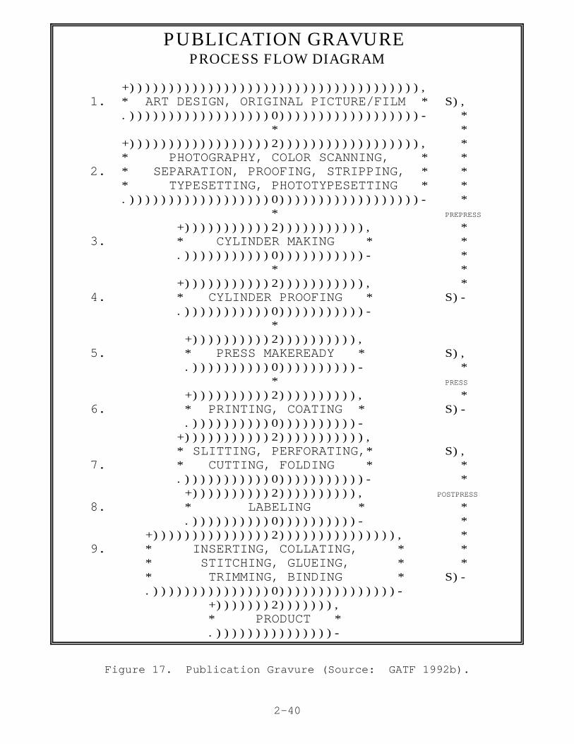
The major types of chemicals used in publication gravure includeadhesives, metal plating solutions, inks, and cleaning solvents. Interms of chemicals, publication gravure differs from packaging andproduct gravure primarily in its heavy reliance on toluene-based ink(GATF 1992b). The publication gravure industry has had littlesuccess with water-based inks (Buonicore). The industry has foundthat in publication gravure where the substrate is always paperstock, water-based inks have not been capable of printingcommercially acceptable quality productions runs of 2,000 to 3,000feet per minute. A process flow diagram as well as information onthe chemicals used in this process are presented in Figure 17.
b. Packaging Gravure
Packaging rotogravure presses are used forprinting folding cartons as well as a variety of other flexiblepackaging materials. In addition to printing, packaging gravurepresses are equipped to fold, cut, and crease paper boxes in acontinuous process. Packages are usually printed on only one side,so the number of print stations is usually about half that requiredfor publication gravure presses. However, in addition to printingstations for the four basic colors, packaging gravure presses mayemploy printing stations for the application of metallic inks andvarnishes as well as laminating stations designed to apply foils tothe paper substrate prior to printing.
Packaging gravure presses are designed with the accurate cuttingand creasing needs of the packaging material in mind. However, imagequality is generally less important in packaging printing than inmost other types of printing and, subsequently, receives lessemphasis.
The chemicals used in packaging gravure are similar to thoseused in publication gravure. However, the inks used in packaginggravure are largely alcohol- and not toluene-based (GATF 1992b). Water-based inks are being successfully used for lower quality, non-process printing on paper and paperboard packaging and for
2-40
PUBLICATION GRAVURE PROCESS FLOW DIAGRAM
+))))))))))))))))))))))))))))))))))))), 1. * ART DESIGN, ORIGINAL PICTURE/FILM * S), .))))))))))))))))))0))))))))))))))))))- * * * +))))))))))))))))))2)))))))))))))))))), * * PHOTOGRAPHY, COLOR SCANNING, * * 2. * SEPARATION, PROOFING, STRIPPING, * * * TYPESETTING, PHOTOTYPESETTING * * .))))))))))))))))))0))))))))))))))))))- * * PREPRESS
+)))))))))))2))))))))))), * 3. * CYLINDER MAKING * * .)))))))))))0)))))))))))- * * * +)))))))))))2))))))))))), * 4. * CYLINDER PROOFING * S)- .)))))))))))0)))))))))))- * +))))))))))2)))))))))), 5. * PRESS MAKEREADY * S), .))))))))))0))))))))))- * * PRESS
+))))))))))2)))))))))), * 6. * PRINTING, COATING * S)- .))))))))))0))))))))))- +)))))))))))2))))))))))), * SLITTING, PERFORATING,* S), 7. * CUTTING, FOLDING * * .)))))))))))0)))))))))))- * +))))))))))2)))))))))), POSTPRESS
8. * LABELING * * .))))))))))0))))))))))- * +)))))))))))))))2))))))))))))))), * 9. * INSERTING, COLLATING, * * * STITCHING, GLUEING, * * * TRIMMING, BINDING * S)- .)))))))))))))))0)))))))))))))))- +)))))))2))))))), * PRODUCT * .)))))))))))))))-
Figure 17. Publication Gravure (Source: GATF 1992b).

2-41
PUBLICATION GRAVURE (cont'd)CHEMICAL/CHEMICAL COMPOUND USAGE
In reference to each step in the process flow diagram:
1. Adhesive, glass cleaner
2. Photographic processing solution, cleaning solvent
3. Chromium plating solution, polishing compound, etching solution, copper platingsolution, nickel plating solution, sulfuric acid solution, degreasing salt, dechromingsolution
4. Cylinder cleaner, gravure ink, cylinder cleaning solvent, roller cleaner, toluene, alkanehydrocarbons
5/6. Gravure ink, imprinting inks, ink remover, splicing cement, ink jet inks
7. None
8. Adhesive, cleaning solvent, adhesive remover
9. Adhesive, adhesive remover
Figure 17. Publication Gravure (continued) (Source: GATF 1992b).

2-42
PUBLICATION GRAVURE (cont'd)MAJOR CHEMICALS USED
Major Chemicals Used (Volumes of Operation/Process Individual Chemicals Used Vary Greatly)
Prepress
Film/glass cleaner Acetone, hexane, 1,1,1-trichloroethane, ethanol, n-propanol,perchloroethylene, 2-butoxy ethanol, isopropanol
Equipment cleaner Isopropanol, hexane, acetone Film developer Sodium sulfite, sulfosalicyclic acid, hydroquinone, potassium
sulfite, potassium hydroxide, butyl-diethanolamine Film fixer Ammonium thiosulfate, sodium acetate, acetic acid,
aluminum sulfate Cylinder making Barium chloride, 1,1,1-trichloroethane, aliphatic petroleum
distillates, ammonium oxalate, ammonium molybdate, bariumformate, calcium benzoate, chromic acid, citric acid, coppersulfate, dicarboxylic acid, cupric tetrafluoborate, ethylacetate, ethylenediamine, formaldehyde, copper, hydrogenperoxide, hydrochloric acid, muriatic acid, isopropanol,phosphoric acid, sodium hydroxide, sulfuric acid, zincchloride
Press
Ink, varnish Hexane, mineral spirits, heptane, lactol spirits, petroleumnaphtha, VM&P naphtha, toluene, xylene, alcohols
Wash solvent Toluene, aliphatic and other aromatic hydrocarbons, ethanol,mineral spirits, acetone, isopropanol
Postpress
Glue, adhesive Paraffin wax, toluene, 1,1,1-trichloroethane, isopropanol
Figure 17. Publication Gravure (continued) (Source: Mathtech).

2-43
printing on non-absorbent packaging substrates such as plastics,aluminum, and laminates (Tyszka 1993). Use of water-based inks isexpected to increase; however, problems still limit their use at pressspeeds above 1,000 feet per minute (Buonicore). A process flowdiagram as well as information on the chemicals used in this processare presented in Figure 18.
c. Product Gravure
The continuous printing surface found on gravurepress cylinders provides the "repeat" required to print the continuouspatterns found on textiles and a variety of other products. In thetextile industry, a gravure heat transfer process using subliming dyesis used to print images on paper. These images are then transferredfrom the paper to a fabric (usually polyester) through a combinationof heat and pressure. The gravure process is also used to printcontinuous patterns on wallboard, wallpaper, floor coverings, andplastics.
The chemicals used in product gravure are similar to those usedin both publication and packaging gravure. However, product gravureuses both water- and solvent-based inks (GATF 1992b). The industryhas used water-based inks successfully on medium-weight papers and onnonabsorbent substrates such as plastics, aluminum, and laminates(Tyszka 1993). However, problems such as paper distortion and curlpersist with lightweight papers (Buonicore). A process flow diagramas well as information on the chemicals used in this process arepresented in Figure 19.
4. Volume of Output and Percentage of Total Market
In 1991 gravure printing accounted for 19 percent ofthe total value of U.S. printing industry output (excluding instantand in-plant printing). Between 1991 and 2025, gravure's market shareis expected to decline to 16 percent of the total U.S. market. Gravure will continue to be the dominant process for the printing oflong-run products such as mass-circulation magazines and catalogs, andcertain types of packaging. However, the long-run products market isrelatively mature and little growth is expected (Bruno 1990, 1991).
5. Number and Relative Size of Printing Companies
Based on a member survey, the Gravure Association ofAmerica reports that there were 1,090 plants with gravure presses in1989 (GAA 1989). Gravure printing is generally used by medium tolarge size printers (Lewis 1992).

2-44
PACKAGING GRAVURE PROCESS FLOW DIAGRAM
+))))))))))))))))))))))))))))))))))))), 1. * ART DESIGN, ORIGINAL PICTURE/FILM * S), .))))))))))))))))))0))))))))))))))))))- * * * +))))))))))))))))))2)))))))))))))))))), * * PHOTOGRAPHY, COLOR SCANNING, * * 2. * SEPARATION, PROOFING, STRIPPING, * * * TYPESETTING, PHOTOTYPESETTING * * .))))))))))))))))))0))))))))))))))))))- * * PREPRESS
+)))))))))))2))))))))))), * 3. * CYLINDER MAKING * * .)))))))))))0)))))))))))- * * * +)))))))))))2))))))))))), * 4. * CYLINDER PROOFING * S)- .)))))))))))0)))))))))))- * +))))))))))2)))))))))), 5. * PRESS MAKEREADY * S), .))))))))))0))))))))))- * * PRESS
+))))))))))2)))))))))), * 6. * PRINTING, COATING * S)- .))))))))))0))))))))))- * +)))))))))))2)))))))))), 7. *LAMINATING, DIECUTTING* S), .)))))))))))0))))))))))- * * * +))))))))))))))))))2)))))))))))))))))), R 8. * INSERTING, COLLATING, * POSTPRESS
* FOLDING, STITCHING, GLUEING, * T * TRIMMING, BINDING * S)- .))))))))))))))))))0))))))))))))))))))- +)))))))2))))))), * PRODUCT * .)))))))))))))))-
Figure 18. Packaging Gravure (Source: GATF 1992b).

2-45
PACKAGING GRAVURE (cont'd)CHEMICAL/CHEMICAL COMPOUND USAGE
In reference to each step in the process flow diagram:
1. Adhesive, glass cleaner
2. Photographic processing solution, cleaning solvent
3. Chromium plating solution, polishing compound, etching solution, copper platingsolution, nickel plating solution, sulfuric acid solution, degreasing salt, dechromingsolution
4. Cylinder cleaner, gravure ink, cylinder cleaning solvent, roller cleaner
5/6. Gravure ink, imprinting inks, ink remover, splicing cement, isopropyl alcohol, ink jetinks
7. Adhesive, cleaning solvent, adhesive remover
8. Adhesive, adhesive remover
Figure 18. Packaging Gravure (continued) (Source: GATF 1992b).

2-46
PACKAGING GRAVURE (cont'd) MAJOR CHEMICALS USED
Major Chemicals Used (Volumes of Operation/Process Individual Chemicals Used Vary Greatly)
Prepress
Film/glass cleaner Acetone, hexane, 1,1,1-trichloroethane, ethanol, n-propanol,perchloroethylene, 2-butoxy ethanol, isopropanol
Equipment cleaner Isopropanol, hexane, acetone Film developer Sodium sulfite, sulfosalicyclic acid, hydroquinone, potassium
sulfite, potassium hydroxide, butyl-diethanolamine Film fixer Ammonium thiosulfate, sodium acetate, acetic acid, aluminum
sulfate Cylinder making Barium chloride, 1,1,1-trichloroethane, aliphatic petroleum
distillates, ammonium oxalate, ammonium molybdate, bariumformate, calcium benzoate, chromic acid, citric acid, coppersulfate, dicarboxylic acid, cupric tetrafluoborate, ethyl acetate,ethylenediamine, formaldehyde, copper, hydrogen peroxide,hydrochloric acid, muriatic acid, isopropanol, phosphoricacid, sodium hydroxide, sulfuric acid, zinc chloride
Press
Ink, varnish Toluene, xylene, mineral spirits, acetone, methyl ethylketone, methyl isobutyl ketone, ethyl acetate, isopropyl acetate,n-propyl acetate, butyl acetate, n-butyl acetate, ethylene glycolmonoethyl ether, methanol, ethanol, isopropanol, tri-decanol
Wash solvent Aliphatic and aromatic hydrocarbons, ethanol, mineral spirits,acetone, toluene, isopropanol
Postpress
Glue, adhesive Paraffin wax, toluene, 1,1,1-trichloroethane, isopropanol
Figure 18. Packaging Gravure (continued) (Source: Mathtech).

2-47
PRODUCT GRAVUREPROCESS FLOW DIAGRAM
+))))))))))))))))))))))))))))))))))))), 1. * ART DESIGN, ORIGINAL PICTURE/FILM * S), .))))))))))))))))))0))))))))))))))))))- * * * +))))))))))))))))))2)))))))))))))))))), * * PHOTOGRAPHY, COLOR SCANNING, * * 2. * SEPARATION, PROOFING, STRIPPING, * * * TYPESETTING, PHOTOTYPESETTING * * .))))))))))))))))))0))))))))))))))))))- * * PREPRESS
+)))))))))))2))))))))))), * 3. * CYLINDER MAKING * * .)))))))))))0)))))))))))- * * * +)))))))))))2))))))))))), * 4. * CYLINDER PROOFING * S)- .)))))))))))0)))))))))))- * +))))))))))2)))))))))), 5. * PRESS MAKEREADY * S), .))))))))))0))))))))))- * * PRESS
+))))))))))2)))))))))), * 6. * PRINTING * S)- .))))))))))0))))))))))- +)))))))))))2))))))))))), 7. * SLITTING, PERFORATING,* * CUTTING, FOLDING * S), .)))))))))))0)))))))))))- R +)))))))))))))2))))))))))))), POSTPRESS
8. * LAMINATING, GLUEING * T .)))))))))))))0)))))))))))))- S)- * +)))))))2))))))), * PRODUCT * .)))))))))))))))-
Figure 19. Product Gravure (Source: GATF 1992b).

2-48
PRODUCT GRAVURE (cont'd)CHEMICAL/CHEMICAL COMPOUND USAGE
In reference to each step in the process flow diagram:
1. Adhesive, glass cleaner
2. Photographic processing solution, cleaning solvent
3. Chromium plating solution, polishing compound, etching solution, copper platingsolution, nickel plating solution, sulfuric acid solution, degreasing salt, dechromingsolution
4. Plate cleaner, gravure ink, cylinder cleaning solvent, roller cleaner
5/6. Gravure ink, imprinting inks, ink remover, splicing cement, isopropyl alcohol, ink jetinks
7. None
8. Adhesive, cleaning solvent, adhesive remover
Figure 19. Product Gravure (continued) (Source: GATF 1992b).

2-49
PRODUCT GRAVURE (cont'd)MAJOR CHEMICALS USED
Major Chemicals Used (Volumes of Operation/Process Individual Chemicals Used Vary Greatly)
Prepress
Film/glass cleaner Acetone, hexane, 1,1,1-trichloroethane, ethanol, n-propanol,perchloroethylene, 2-butoxy ethanol, isopropanol
Equipment cleaner Isopropanol, hexane, acetone Film developer Sodium sulfite, sulfosalicyclic acid, hydroquinone, potassium
sulfite, potassium hydroxide, butyl-diethanolamine Film fixer Ammonium thiosulfate, sodium acetate, acetic acid, aluminum
sulfate Cylinder making Barium chloride, 1,1,1-trichloroethane, aliphatic petroleum
distillates, ammonium oxalate, ammonium molybdate, bariumformate, calcium benzoate, chromic acid, citric acid, coppersulfate, dicarboxylic acid, cupric tetrafluoborate, ethyl acetate,ethylenediamine, formaldehyde, copper, hydrogen peroxide,hydrochloric acid, muriatic acid, isopropanol, phosphoricacid, sodium hydroxide, sulfuric acid, zinc chloride
Press
Ink, varnish Toluene, xylene, mineral spirits, acetone, methyl ethylketone, methyl isobutyl ketone, ethyl acetate, isopropyl acetate,n-butyl acetate, ethylene glycol monoethyl ether, methanol,ethanol, isopropanol, tri-decanol
Wash solvent Aliphatic and aromatic hydrocarbons, ethanol,mineral spirits,acetone, toluene, isopropanol
Postpress
Glue, adhesive Paraffin wax, toluene, 1,1,1-trichloroethane, isopropanol
Figure 19. Product Gravure (continued) (Source: Mathtech)

2-50
C. Flexography
1. Flexographic Platemaking
Flexographic plates are relief plates made of eitherrubber or ultraviolet light sensitive polymers (i.e.,photopolymers). The first step in making a rubber flexographicplate is the production of an engraving of the job using aphotomechanical process. Once finished, the engraving is placed ina mold press. The mold is produced by pressing the mold material,which can be either plastic or glass, against the engraving undercontrolled temperature and pressure. The resulting mold is thenused to make a rubber flexographic plate; a rubber sheet is pressedinto the mold under pressure and elevated temperature.
The production of photopolymer flexographic plates is adirect-to-plate process that does not require an original plate ormold. The process differs depending on whether solid sheets ofphotopolymer or liquid photopolymer are used, though the twoprocesses are similar in general outline. In both processes theplates are made in ultraviolet exposure units. A negative of thejob is placed between the photopolymer and the ultraviolet lightsource. The photopolymer sheet or liquid is then exposed toultraviolet light, hardening the image area. Lastly, the plate isprocessed to remove the unhardened non-image area. Photopolymerplates are replacing rubber plates because they offer superiorquality and performance at a lower cost.
2. Flexographic Presses and Printing
Flexographic presses combine features of bothletterpress and rotogravure printing. Like letterpress, theprocess uses relief plates and, like rotogravure, it uses low-viscosity, fast-drying inks. Typically, the plates are made oflow-cost rubber or photopolymer. Inexpensive, durable platescoupled with simple printing techniques and the use of a two rollersystem to distribute ink onto the plate cylinder allow for easymakeup and cleanup. As a result, flexography is one of the leastexpensive printing processes. Flexographic presses are capable ofproducing good quality impressions on many different substrates.Figure 20 presents schematics of a web-fed rotary press and a threeroller ink system typical of those used in flexographic printing.
The five types of printing presses used for flexographicprinting are the stack type, central impression cylinder (CIC), in-line, newspaper unit, and dedicated 4-, 5-, or 6-color unitcommercial publication flexographic presses. All five types employa plate cylinder, a metering cylinder known as the anilox

2-51
Figure 20. Web-fed Rotary Flexographic Press (top) andThree Roller Ink System (Source: Adams 1988. Reproduced bypermission. Printing Technology, 3rd Edition by J. MichaelAdams, David D. Faux and Lloyd Reiber, Delmar Publishers,
Inc., Albany, New York, Copyright 1988)

2-52
roll that applies ink to the plate, and an ink pan. Some presses usea third roller as a fountain roller and, in some cases, a doctorblade for improved ink distribution.
The stack press is characterized by one or more stacks ofprinting stations arranged vertically on either side of the pressframe. Each stack has its own plate cylinder which prints one colorof a multicolor impression. All stations are driven from a commongear train. Stack presses are easy to set up and can print bothsides of the web in one pass. They can be integrated with winders,unwinders, cutters, creasers, and coating equipment. They are verypopular for milk carton printing. A drawback of stack presses istheir poor registration; the image position on every printed sheet isnot as consistent as in many other printing processes.
Central impression cylinder (CIC) presses use a singleimpression cylinder mounted in the press frame. Two to eight colorprinting stations surround the central impression cylinder. Eachstation consists of an ink pan, fountain roller, anilox roll, doctorblade, and plate cylinder. As the web enters the press it comes intocontact with the impression cylinder and remains in contact until itleaves the press. The result is precise registration which allowsCIC presses to produce very good color impressions.
The in-line flexographic press is similar to the stacked pressexcept the printing stations are arranged in a horizontal line. Theyare all driven by a common line shaft and may be coupled to folders,cutters, and other postpress equipment. These presses are used forprinting bags, corrugated board, folding boxes, and similar products.
A newspaper flexographic press consists of multiple printingunits, each unit consisting of two printing stations arranged back-to-back in a common frame. The use of paired stations allows bothsides of the web to be printed in one pass. Multiple printingstations are required to print the many pages that make up a typicalnewspaper. Single and double color decks, stacked units, or 4-, 5-,or 6-color units are sometimes positioned above those units where thepublisher wants to provide single or multiple spot color, spot colorfor both sides of the web, or process color, respectively(Buonicore).
Commercial publication flexographic presses are compact high-speed presses with wide web capability that utilize dedicated 4-, 5-,or 6-color units. Typically, two four-color units are paired in onepress to allow printing on both sides of the web. Publicationflexographic presses generally incorporate infrared dryers to ensuredrying of the waterborne ink after each side of the web is printed(Buonicore).
There are two primary reasons why flexography is graduallybecoming a major player in the printing industry: 1) it is arelatively simple operation; and 2) it is easily adapted to the use

2-53
of water-based inks. The widespread use of water-based inks inflexographic printing means a large reduction in VOC emissioncompared to the heatset web or gravure printing processes.Publication flexography is used mainly in the production ofnewspaper, comics, directories, newspaper inserts, and catalogs.Packaging flexography is used for the production of folding cartons,labels, and packaging materials. Large quantities of inks are usedduring normal runs on flexographic presses; however, some printersare able to recycle a majority of their spent inks and wash waters.
Major chemicals used in flexography include platemakingsolution, water and solvent based inks, and blanket/roller cleaningsolvents. Figure 21 presents a process flow diagram as well asinformation on the chemicals used in publication flexography. Figure22 presents this information for packaging flexography (GATF 1992b).
3. Volume of Output and Percentage of Total Market
In 1991, flexographic printing accounted for 17percent of the total value of U.S. printing industry output(excluding instant and in-plant printing). Between 1991 and 2025,however, flexography's share of the market is expected to increase to21 percent. Growth areas for flexography which recently replacedletterpress as the major relief printing process, are expected to bepreprinted labels for corrugated boxes, pressure sensitive labels,newspaper inserts, comic books, and directories and catalogs (Bruno1990, 1991).
4. Number and Relative Size of Printing Companies
Of a total of 59,636 plants with printing presses,only 1,587, or 2.7 percent, have flexographic presses. Flexographicprinters, however, tend to be larger than printers using otherprocesses. Almost 55 percent of plants with flexographic presseshave 20 or more employees compared to less than 16 percent in theprinting industry as a whole (A.F. Lewis 1991).
D. Letterpress
1. Letterpress Platemaking
Letterpress and flexographic plates are made using thesame basic technology. The two basic types of plates used inletterpress printing are original plates and duplicate plates. Onlyduplicate plates are used in flexography.

2-54
PUBLICATION FLEXOGRAPHY PROCESS FLOW DIAGRAM
+))))))))))))))))))))))))))))))))))))), 1. * ART DESIGN, ORIGINAL PICTURE/FILM * S), .))))))))))))))))))0))))))))))))))))))- * * * +))))))))))))))))))2)))))))))))))))))), * * PHOTOGRAPHY, COLOR SCANNING, * * 2. * SEPARATION, PROOFING, STRIPPING, * * * TYPESETTING, PHOTOTYPESETTING * * .))))))))))))))))))0))))))))))))))))))- * * PREPRESS
+))))))))))))))))))2)))))))))))))))))), * 3. * FILM PROCESSING AND ASSEMBLY * * .))))))))))))))))))0))))))))))))))))))- * * * +)))))))2))))))), * 4. * PLATEMAKING * S)- .)))))))0)))))))- * +))))))))))2)))))))))), 5. * PRESS MAKEREADY * S), .))))))))))0))))))))))- * * PRESS
+))))))))))2)))))))))), * 6. * PRINTING, COATING * S)- .))))))))))0))))))))))- * +))))))))))2)))))))))), 7. * LABELING * S), .))))))))))0))))))))))- * * * +))))))))))))))))))2)))))))))))))))))), R 8. * INSERTING, COLLATING, * POSTPRESS
* FOLDING, STITCHING, GLUEING, * T * TRIMMING, BINDING * S)- .))))))))))))))))))0))))))))))))))))))- +)))))))2))))))), * PRODUCT * .)))))))))))))))-
Figure 21. Publication Flexography (Source: GATF 1992b).

2-55
PUBLICATION FLEXOGRAPHY (cont'd)CHEMICAL/CHEMICAL COMPOUND USAGE
In reference to each step in the process flow diagram:
1. Glue, cleaning solvent, class cleaner
2. Glue
3. Film fixer, film developer, film cleaner, antistatic spray
4. Platemaking photopolymer, plate washing, defoamer, plate etching compound,plate cleaning liquid, isopropyl alcohol
5. Microbial agent
6. Flexo ink (solvent- or water-based), varnish blanket and roller wash, inkcleaner/remover, plate preserver
7. Adhesive
8. Adhesive
Figure 21. Publication Flexography (continued).

2-56
PUBLICATION FLEXOGRAPHY (cont'd)MAJOR CHEMICALS USED
Major Chemicals Used (Volumes of Operation/Process Individual Chemicals Used Vary Greatly)
Prepress
Film/glass cleaner Acetone, hexane, 1,1,1-trichloroethane, ethanol, n-propanol,perchloroethylene, 2-butoxy ethanol, isopropanol
Equipment cleaner Isopropanol, hexane, acetone Film developer Sodium sulfite, sulfosalicyclic acid, hydroquinone, potassium
sulfite, potassium hydroxide, butyl-diethanolamine Film fixer Ammonium thiosulfate, sodium acetate, acetic acid, aluminum
sulfate Flexoplatemaking Methacrylate monomer, organic
solution phosphorous compounds, petroleum distillates, anionicsurfactants, potassium hydroxide
Press
Ink Benzisothiazolinon, ethylenediamine, ammonium hydroxide,antimicrobial agents, isopropanol, toluene
Wash solvent/plate Aliphatic and aromatic hydrocarbons, ethanol, mineral cleaner spirits, acetone, toluene Wash solution Ethylene glycol monoethyl ether, amines, ammonia
Postpress
Glue, adhesive Paraffin wax
Figure 21. Publication Flexography (continued).

2-57
PACKAGING FLEXOGRAPHY PROCESS FLOW DIAGRAM
+))))))))))))))))))))))))))))))))))))), 1. * ART DESIGN, ORIGINAL PICTURE/FILM * S), .))))))))))))))))))0))))))))))))))))))- * * * +))))))))))))))))))2)))))))))))))))))), * * PHOTOGRAPHY, COLOR SCANNING, * * 2. * SEPARATION, PROOFING, STRIPPING, * * * TYPESETTING, PHOTOTYPESETTING * * .))))))))))))))))))0))))))))))))))))))- * * PREPRESS
+))))))))))))))))))2)))))))))))))))))), * 3. * FILM PROCESSING AND ASSEMBLY * * .))))))))))))))))))0))))))))))))))))))- * * * +)))))))2))))))), * 4. * PLATEMAKING * S)- .)))))))0)))))))- * +))))))))))2)))))))))), 5. * PRESS MAKEREADY * S), .))))))))))0))))))))))- * * PRESS
+))))))))))2)))))))))), * 6. * PRINTING, COATING * S)- .))))))))))0))))))))))- * +))))))))))))2)))))))))))), 7. * LAMINATING, DIECUTTING * S), .))))))))))))0))))))))))))- * * * +))))))))))))))))))2)))))))))))))))))), R 8. * INSERTING, COLLATING, * POSTPRESS
* FOLDING, STITCHING, GLUEING, * T * TRIMMING, BINDING * S)- .))))))))))))))))))0))))))))))))))))))- +)))))))2))))))), * PRODUCT * .)))))))))))))))-
Figure 22. Packaging Flexography (Source: GATF 1992b).

2-58
PACKAGING FLEXOGRAPHY (cont'd)CHEMICAL/CHEMICAL COMPOUND USAGE
In reference to each step in the process flow diagram:
1. Adhesive
2. Cleaning solvent, adhesive
3. Film fixer, film developer, film cleaning solvent
4. Platemaking fluid, spent platemaking fluid neutralization compound, muriaticacid
5. Plate cleaning solvent, ink, plating cleaning solution
6. Plate cleaner, plate preserver, flexo ink, varnish, roller cleaning solvent
7. Adhesive, adhesive remover
8. Adhesive, adhesive remover
- Specialty operations:
Lamination (glue)
Figure 22. Packaging Flexography (continued).
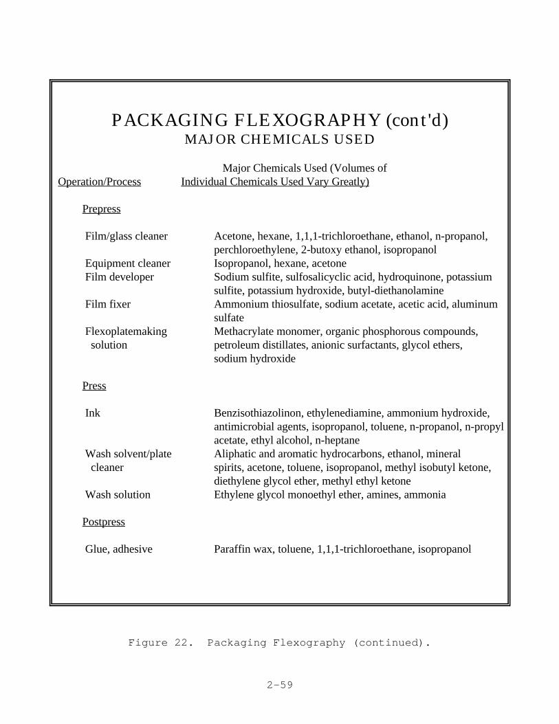
2-59
PACKAGING FLEXOGRAPHY (cont'd)MAJOR CHEMICALS USED
Major Chemicals Used (Volumes of Operation/Process Individual Chemicals Used Vary Greatly)
Prepress
Film/glass cleaner Acetone, hexane, 1,1,1-trichloroethane, ethanol, n-propanol,perchloroethylene, 2-butoxy ethanol, isopropanol
Equipment cleaner Isopropanol, hexane, acetone Film developer Sodium sulfite, sulfosalicyclic acid, hydroquinone, potassium
sulfite, potassium hydroxide, butyl-diethanolamine Film fixer Ammonium thiosulfate, sodium acetate, acetic acid, aluminum
sulfate Flexoplatemaking Methacrylate monomer, organic phosphorous compounds,
solution petroleum distillates, anionic surfactants, glycol ethers,sodium hydroxide
Press
Ink Benzisothiazolinon, ethylenediamine, ammonium hydroxide,antimicrobial agents, isopropanol, toluene, n-propanol, n-propylacetate, ethyl alcohol, n-heptane
Wash solvent/plate Aliphatic and aromatic hydrocarbons, ethanol, mineral cleaner spirits, acetone, toluene, isopropanol, methyl isobutyl ketone,
diethylene glycol ether, methyl ethyl ketone Wash solution Ethylene glycol monoethyl ether, amines, ammonia
Postpress
Glue, adhesive Paraffin wax, toluene, 1,1,1-trichloroethane, isopropanol
Figure 22. Packaging Flexography (continued).

2-60
Original plates are made by photomechanical means from artworkor photographs that have been converted to either line or half-tonenegatives. The negatives are used to produce either a photoengravedor photopolymer plate. When the original plates themselves are usedfor printing, they are called direct plates. Generally, direct platesare used for very short press runs. Duplicate plates, cast in moldsmade from original plates, are used for longer press runs.
a. Original Plates
Today, original plates are made either from avariety of metals by acid etching methods or from photopolymerplastics. Metal plates are commonly referred to as photoengravingsor engravings. The three types of engravings used, line, half-tone,and combination, are dependent on the type of film negative used toexpose the plate prior to engraving. Photoengravings are made inunits smaller than the size of the press cylinder allowing several tobe mounted on the cylinder to produce a complete image. Becauserotary presses dominate the market, letterpress printing generallyrequires curved plates.
A second type of letterpress plate, the wraparound plate, ismade using the same general process as used for photoengraving.However, letterpress wraparound plates are mounted in one piece andcover the entire surface of the cylinder. Wraparound letterpressplates are used for both dry offset and direct printing.
Photoengraved plates are produced on 16 gauge zinc, copper, ormagnesium. Copper is usually used for halftone plates and zinc andother metals for line engravings. Photosensitive coatings used inplate preparation are bichromated shellac for zinc and magnesiumplates and bichromated glue for copper plates. Photocrosslinkingpolymers are also used for some plates. After exposure, the metalplates are subjected to an acid bath where the non-printing areas areetched away by the acid. Large non-printing areas may be removed bymechanical routing. Nitric acid is frequently used to etch zinc andmagnesium plates while a ferric chloride solution is used for copperplates.
A major problem during etching is undercutting, the unwantedsideways etching that can undercut the resist and adversely effectdot size and line width on the plate. Today a technique known aspowderless etching is used to prevent this problem. In powderlessetching, the etching bath consists of an emulsion of nitric acid,oils, and a wetting agent. As the acid attacks the plate, thewetting agent and oil form a banking agent that clings to the sidesof the etched areas and prevents sideways etching. This system hasbeen adopted for use on zinc, magnesium, copper and aluminum plates.Chemically, the emulsions used for etching copper and aluminum plates
2-61
are quite different from those used for zinc and magnesium plates.Powderless etching can be used for original photoengraved plates aswell as wraparound plates.
Photopolymer plates can be used for original and wraparoundapplications or for making duplicate plates. The photopolymer platesin use today are typically proprietary products and include Dycril,Nyloprint, Letterflex, Dynaflex, NAPP, and Merigraph plates.
Du Pont Dycril plates, introduced in 1959, are used in a widevariety of flat, rotary, and wraparound letterpress applications aswell as letterset applications. These plates also serve as patternsfor making duplicate plates. Dycril plates consist of a layer oflight-sensitive plastic bonded to a metal or film substructure. Whenthe plate is exposed to UV light through a halftone or line typenegative, the exposed areas of the plastic coating is polymerized andbecomes hardened. The unexposed coating can be washed away using analkaline spray.
Nyloprint plates, produced by BASF, Corp., are made of aphotosensitive nylon layer bonded to a backing material, usuallyaluminum, steel, or distortion resistant foil. These plates areused on cylinder presses for printing magazines and other long runjobs.
Letterflex plates, manufactured by W. R. Grace & Co., are usedextensively in newspaper and book printing. They consist of a liquidphotosensitive prepolymer applied as a coating to a polyester sheet.A machine performs both the coating and exposure process in oneoperation. The liquid prepolymer is converted to a solid polymer onexposed areas of the sheet. The liquid prepolymer remaining on theunexposed areas is then removed. Used on cylinder presses,Letterflex plates are very durable.
Dynaflex plates, used primarily by the newspaper industry,consist of a dry prepolymer photosensitive coating on a metalsubstrate. Once exposed, processing is similar to other photopolymerplates. The unexposed areas of the plate is easily removed by water.
NAPP plates, developed in Japan but manufactured in the U.S. byLee Enterprises, Inc., use a denatured polyvinyl alcohol coatingbonded to a steel or aluminum backing. The plates are delivered tothe printer in a presensitized state that are ready for exposurewithout any other processing. After exposure, the plate is washed inwater to remove the unexposed material. These plates are usedprimarily for letterpress applications but they can be easily adaptedto gravure and lithographic operations.
Merigraph plates, developed in Japan but manufactured in theU.S. by Hercules, Inc., use a liquid unsaturated polyester

2-62
photopolymer similar to that found on the Letterflex plate. Amachine is used to coat the plate just prior to exposure.
b. Duplicate Plates
A duplicate is a plate cast in a mold made froman original plate. Duplicate plates are used because they can bemade from a number of durable materials resulting in plates withlonger service lives than is possible with original plates.Furthermore, if a duplicate plate is damaged, a new duplicate canquickly be produced from the original. Curved duplicate plates areproduced to fit modern press cylinders.
Duplicate plates fall into four general categories: stereotype,electrotype, plastic, and rubber. Each of these types of plates aredescribed in greater detail below.
Stereotype plates are used only for letterpress newspaperprinting. A stereotype plate is prepared by first making a paper-mache mat or mold from the original plate. Molten metal is thenpoured into the paper-mache mold to form the press plate. The metalused depends on the length of the press run. For long runs nickel,chromium, or iron are used.
Electrotype plates are used in letterpress operations where highquality is required. This includes commercial printing, books, andmagazines. An impression or mold of the original is made using hotplastic. The mold is then plated with silver to make it conductive.The coated mold is then electroplated with a thin layer of copper ornickel. The resulting shell is removed from the mold and backed withmolten metal to give it strength. The face can then be plated withnickel, iron, or chromium for long press runs.
Plastic and rubber plates are prepared in a process similar tothe one used to make electrotype plates. The use of plastic orrubber makes the plates very lightweight and low-cost. Plasticplates are made from thermoplastic vinyl resins. Currently, however,use of this type of plate is not widespread due largely to thetoxicity of the vinyl monomers used.
Rubber plates can be molded from either natural or syntheticrubber or some combination of the two. These plates are used onflexographic presses for printing wrapping paper, bags, envelopes,corrugated boxes, milk cartons, and any application where theflexible characteristics of rubber assist printing on irregular andrough surfaces. These plates are also used for special "centralimpression presses" used to print flexible films used in packaging.

2-63
2. Letterpress Presses and Printing
Letterpress printing dates back to the earliestmethods for applying an image to paper. The three types ofletterpress presses in use today are platen, flat-bed, and rotarypresses. Schematic representations of two of the most common typesof letterpress presses, the unit-design perfecting rotary press andthe rotary letterpress typically used for magazine printing, areshown in Figure 23.
Platen presses have been in continuous use since Gutenberg firstinvented the printing press. A platen press is made up of two flatsurfaces called the bed and the platen. The plate containing theimage is placed on the bed and locked down. The platen provides asmooth backing for the paper or other substrate that is to beprinted. The plate is inked and then the platen presses thesubstrate against the plate producing the impression. Some platenpresses are arranged with the bed and platen in the vertical plane.
The plate is inked with an inking roller that transfers ink froman inking plate to the image carrier. Ink is placed on the inkingplate by an ink fountain roller. The platen style press has beenwidely used in printing small-town newspapers since the late 1800s.The printing area is usually limited to a maximum of 18 inches by 24inches. These presses are also used to print letterhead, billheads,forms, posters, announcements, and many other types of printedproducts, as well as for imprinting, embossing, and hot-leafstamping.
Flat-bed cylinder presses use either vertical or horizontalbeds. These presses can print either one or two-color impressions.Flat-bed cylinder presses, which operate in a manner similar to theplaten press, will print stock as large as 42 inches by 56 inches.The plate is locked to a bed which passes over an inking roller andthen against the substrate. The substrate passes around animpression cylinder on its way from the feed stack to the deliverystack. Ink is supplied to the plate cylinder by an inking roller andan ink fountain. Flat-bed cylinder presses are slow, having aproduction rate of not more than 5,000 impressions per hour. As aresult, much of the printing formerly done on this type of press isnow done using rotary letterpress or lithography. The horizontal bedpress, the slower of the two types of flat-bed cylinder press, is nolonger manufactured in the United States.
Rotary presses are currently the most popular type of press usedin letterpress operation. They can be either sheet-fed or web-fedand, in construction, are similar to other sheet-fed and web-fedpresses. Like all rotary presses, rotary letterpress requires curvedimage carrying plates. The most popular types of plates used arestereotype, electrotype, and molded plastic or

2-64
Figure 23. Unit-design Perfecting Rotary Press (top) andRotary Letterpress Typically Used for Magazine Printing(Source: Field 1980. Reproduced by permission of Ayer
Company Publishers, Inc.)

2-65
rubber. When printing on coated papers, rotary presses use heat-setinks and are equipped with dryers, usually the high-velocity hot airtype.
Web-fed rotary letterpress presses are used primarily forprinting newspapers. These presses are designed to print both sidesof the web simultaneously. Typically, they can print up to fourpages across the web; however, some of the new presses can print upto six pages across a 90-inch web. Rotary letterpress is also usedfor long-run commercial, packaging, book, and magazine printing.
Major chemicals used in letterpress printing, very similar tothose used in lithography, include film developers and fixers, inks,and blanket and roller washes (GATF 1992b). A process flow diagramas well as information on the chemicals used in this process arepresented in Figure 24.
3. Volume of Output and Percentage of Total Market
Prior to the Second World War letterpress was thedominant printing process, but since the mid-1940s it has beengradually replaced by other printing processes. In 1991, letterpressprinting accounted for 11 percent of the total value of U.S. printingindustry output (excluding instant and in-plant printing). However,between 1991 and 2025, letterpress' market share is expected todecline dramatically to only four percent of the total U.S. market.By 2025, letterpress will no longer rank as a major printing process.Gravure has largely replaced letterpress in the printing of long-runmagazines and catalogs while flexography is replacing it for printingpaperbacks, labels, business forms, newspapers, and directories(Bruno 1990, 1991).
4. Number and Relative Size of Printing Companies
In 1982, the latest year for which data are available,20,786 plants used letterpress presses. More recent data wasavailable on the number of plants with sheetfed letterpress presses;in 1988, there were 18,961 plants with this type of press. In 1982,over 83 percent of plants with letterpress presses had fewer than 20employees and almost 46 percent had fewer than five. In 1988, almost85 percent of plants with sheetfed letterpress presses had fewer than20 employees and 44 percent had fewer than five (A.F. Lewis 1991).

2-66
LETTERPRESSPROCESS FLOW DIAGRAM
+))))))))))))))))))))))))))))))))))))), 1. * ART DESIGN, ORIGINAL PICTURE/FILM * S), .))))))))))))))))))0))))))))))))))))))- * * * +))))))))))))))))))2)))))))))))))))))), * * PHOTOGRAPHY, COLOR SCANNING, * * 2. * SEPARATION, PROOFING, STRIPPING, * * * TYPESETTING, PHOTOTYPESETTING * * .))))))))))))))))))0))))))))))))))))))- * * PREPRESS
+))))))))))))))))))2)))))))))))))))))), * 3. * FILM PROCESSING AND ASSEMBLY * * .))))))))))))))))))0))))))))))))))))))- * * * +)))))))2))))))), * 4. * PLATEMAKING * S)- .)))))))0)))))))- * +))))))))))2)))))))))), 5. * PRESS MAKEREADY * S), .))))))))))0))))))))))- * * PRESS
+))))))))))2)))))))))), * 6. * PRINTING * S)- .))))))))))0))))))))))- * * +))))))))))))))))))2)))))))))))))))))), * DIECUTTING, INSERTING, COLLATING, * 7. * FOLDING, STITCHING, GLUEING, * POSTPRESS
* LAMINATING, TRIMMING, BINDING * .))))))))))))))))))0))))))))))))))))))- +)))))))2))))))), * PRODUCT * .)))))))))))))))-
Figure 24. Letterpress (Source: GATF 1992b).

2-67
LETTERPRESS (cont'd)CHEMICAL/CHEMICAL COMPOUND USAGE
In reference to each step in the process flow diagram:
1. Adhesive, cleaning solvent
2. Color scanner cleaner, deletion fluid
3. Film developer and fixer, film cleaner, film system cleaner, image cleaner/preserver,antistatic spray, adhesive
4. Plate developer and finisher, plate toner, plate system cleaner
5. Letterpress ink, blanket wash, roller wash, copperizing solution, anti-setoffpowder
6. Adhesive, ink
7. Adhesive
- Specialty operations:
Lamination (glue, varnish, plastics) Cellophane window (glue)
Figure 24. Letterpress (continued).

2-68
LETTERPRESS OPERATION (cont'd)MAJOR CHEMICALS USED
Major Chemicals Used (Volumes of Operation/Process Individual Chemicals Used Vary Greatly)
Prepress
Film/glass cleaner Acetone, hexane, 1,1,1-trichloroethane, ethanol, n-propanol,perchloroethylene, 2-butoxy ethanol, isopropanol
Equipment cleaner Isopropanol, hexane, acetone Film developer Sodium sulfite, sulfosalicyclic acid, hydroquinone, potassium
sulfite, potassium hydroxide, butyl-diethanolamine Film fixer Ammonium thiosulfate, sodium acetate, acetic acid, aluminum
sulfate Plate developer Surfactant, Benzyl alcohol, diethanolamine, polyvinyl alcohol,
ethylene glycol, thiol compounds, acetic acid Plate Photosensitive polymers
Press
Ink, varnish Petroleum distillates, vegetable oil, resin, rosin, toluene,isopropanol, xylene,pigments containing barium and copper
Ink thinner Hydrotreated or solvent extracted naphthenic distillates Wash solvent Aliphatic and aromatic hydrocarbons, ethanol, turpentine,
acetone Linotype Lead, zinc, tin
Postpress
Glue Paraffin wax, methanol, hexane, acetone, ethylene dichloride,methyl ethyl ketone, polyglycol dimethacrylates, methylcyanoacrylates, toluene
Figure 24. Letterpress (continued).

2-69
E. Screen Printing
1. Screen Preparation
A typical image carrier used in screen printingconsists of a screen made from a very finely woven fabric. The imageis defined by a stencil or mask which is adhered to the fabricscreen. Ink will pass through the fabric except where the stencil isapplied, thus forming an image on the printing substrate. The fabricis typically stretched taught over a wooden or metal frame. Theresulting shallow container formed by the frame will hold a quantityof ink which is pressed through the fabric by a squeegee that isdrawn across the screen by the printing press.
a. Screen Fabrics
Silk was the original material used to makescreens for screen printing. Today, various synthetic material arethe dominant screen materials. By far the most widely used fabric ismonofilament polyester followed by multifilament polyester and nylon.Other screen materials include: calendared monofilament polyester,metallized monofilament polyester, carbonized polyester, glass, wiremesh, and stainless steel. Screens made of the same material candiffer in thread diameter, number of threads-per-inch, and choice ofmono- or multifilament fibers. Need for various characteristics suchas wearability and dimensional stability will help determine thefabric selected for a particular screen printing job. Diameter ofmesh thread and number of threads per inch determine the amount ofink transferred to the substrate during the printing process(Buonicore and SPAI 1991).
b. Stencils
The stencil, used to cover the non-printing areaof the screen, must be of a material that is impermeable to thescreen printing ink. Materials used for stencils include plainpaper, shellac or lacquer coated paper, lacquer film, photographicfilm, and light-sensitive emulsions. Stencil types availableinclude: hand-cut film, photographic film, direct coating,direct/indirect photostencil, and wet-direct photostencil.
A hand-cut film stencil is made by hand cutting the image areasfrom a lacquer film sheet on a paper backing. A liquid adhesive isthen used to bond the stencil to the screen fabric. Once theadhesive has dried, the film's paper backing sheet is removed.
Two types of photographic film, presensitized and unsensitized,are available for use in the preparation of stencils. Presensitized
2-70
film is ready to use as purchased, while unsensitized film must firstbe treated with a photosensitization solution. In preparing thestencil, the film is exposed to a positive film image in a vacuumframe. It is then developed in a solution that renders the unexposedimage areas soluble in water. The soluble areas are removed and theremaining film is bonded to the screen fabric.
In the direct coating process, a light-sensitive emulsion isapplied to the entire screen and allowed to dry. The screen is thenexposed to a film positive image. The non-image areas of theemulsion harden upon exposure. However, the coating in the unexposedimage areas remains soluble and is removed with a spray of warmwater. Several coats of the light-sensitive material are applied andsmoothed to achieve a long wearing screen.
The preparation of direct/indirect stencils combines elements ofboth the photographic film and the direct coating methods. Anunsensitized photographic film is laminated to the screen and thensensitized by the direct application of a photosensitive emulsion.The exposed stencil is processed in a manner similar to that used inthe preparation of stencils produced by the photographic film and thedirect coating methods. The direct/indirect process produces highlydurable stencils that are used in applications where high printquality is required.
A recent development in stencil preparation is the wet-directphotostencil process. To prepare a stencil using this process, afilm positive is held in direct contact with a wet photopolymeremulsion. The emulsion hardens when exposed to UV light. Theunexposed areas of emulsion are then removed yielding a very durable,high quality screen.
2. Screen Presses and Printing
Reduced to its basics, screen printing consists ofthree elements: the screen which is the image carrier; the squeegee;and ink. The screen is placed in a wooden, steel, or aluminumframe and pulled taught. Proper tension is essential to accuratecolor registration. The stencil is then applied to the non-imageareas of the screen to render them impervious to ink. The imageareas remain porous.
The squeegee is a blade that is drawn across the screen to forceink through its porous image areas and onto the substrate. Manyfactors such as composition, size and form, angle, pressure, andspeed of the blade determine the quality of the impression. At onetime most blades were made from rubber which, however, is prone towear and edge nicks and has a tendency to warp and distort. Whileblades continue to be made from rubbers such as neoprene, most are

2-71
now made from polyurethane which can produce as many as 25,000impressions without significant degradation of the image.
A significant characteristic of screen printing is that agreater thickness of the ink can be applied to the substrate than ispossible with other printing techniques. This allows for some veryinteresting effects that are not possible using other printingmethods. Because of the simplicity of the application process, awider range of inks and dyes are available for use in screen printingthan for use in any other printing process.
Until relatively recently all screen printing presses weremanually operated. Now, however, most commercial and industrialscreen printing is done on single and multicolor automated presses.Three types of presses are used by the screen printing industry:flat-bed (probably the most widely used), cylinder, and rotary.Flat-bed and cylinder presses are similar in that both use a flatscreen and a three step reciprocating process to perform the printingoperation. The screen is first moved into position over thesubstrate, the squeegee is then pressed against the mesh and drawnover the image area, and then the screen is lifted away from thesubstrate to complete the process. With a flat-bed press thesubstrate to be printed is positioned on a horizontal print bed thatis parallel to the screen. With a cylinder press the substrate ismounted on a cylinder (Field and Buonicore).
Rotary screen presses are designed for continuous, high speedweb printing. The screens used on rotary screen presses are seamlessthin metal cylinders. The open-ended cylinders are capped at bothends and fitted into blocks at the side of the press. Duringprinting, ink is pumped into one end of the cylinder so that a freshsupply is constantly maintained. The squeegee is a free floatingsteel bar inside the cylinder and squeegee pressure is maintained andadjusted by magnets mounted under the press bed. Rotary screenpresses are most often used for printing textiles, wallpaper, andother products requiring unbroken continuous patterns. Figure 25depicts two types of screen presses, flat-bed and rotary.
Screen printing is arguably the most versatile of all printingprocesses. It can be used to print on a wide variety of substrates,including paper, paperboard, plastics, glass, metals, fabrics, andmany other materials. The major chemicals used include screenemulsions, inks, and solvents, surfactants, caustics and oxidizersused in screen reclamation. The inks used vary dramatically in theirformulations (GATF 1992b). A process flow diagram as well asinformation on the chemicals used in this process are presented inFigure 26.

2-72
Figure 25. Flat-bed Screen Press (top) and Rotary Screen Press(Source: Field 1980. Reproduced by permission of Ayer
Company Publishers, Inc.)

2-73
SCREEN PRINTINGPROCESS FLOW DIAGRAM
+))))))))))))))))))))))))))))))))))))), 1. * ART DESIGN, ORIGINAL PICTURE/FILM * S), .))))))))))))))))))0))))))))))))))))))- * * * +))))))))))))))))))2)))))))))))))))))), * * PHOTOGRAPHY, COLOR SCANNING, * * 2. * SEPARATION, PROOFING, STRIPPING, * * * TYPESETTING, PHOTOTYPESETTING * * .))))))))))))))))))0))))))))))))))))))- * * PREPRESS
+))))))))))))))))))2)))))))))))))))))), * 3. * * * * STENCIL & SCREEN PREPARATION * * * SCREEN MAKING * * .))))))))))))))))))0))))))))))))))))))- * * S)- +))))))))))))2))))))))))))), 4. * * * FOOTPRINT, PRINTING * PRESS
* * .))))))))))))0)))))))))))))- * +))))))))))))2))))))))))))), 5. * * * SCREEN RECLAMATION * POSTPRESS
* * .))))))))))))0)))))))))))))- * +))))))))2))))))))), * PRODUCT * .))))))))))))))))))-
Figure 26. Screen Printing (Source: GATF 1992b).

2-74
SCREEN PRINTING (cont'd)CHEMICAL/CHEMICAL COMPOUND USAGE
In reference to each step in the process flow diagram:
1. Adhesive, cleaning solvent
2. Cleaning solvent, film fixer and developer
3. Mesh preparation compounds, abrading compounds, degreasers, adhesives,stencil/emulsion systems, blockout solution
4. Screen printing ink, haze remover
5. Ink remover, stencil remover
Figure 26. Screen Printing (continued).

2-75
SCREEN PRINTING OPERATION (cont'd)MAJOR CHEMICALS USED
Major Chemicals Used (Volumes of Operation/Process Individual Chemicals Used Vary Greatly)
Prepress
Film developer Sodium sulfite, sulfosalicyclic acid, potassium hydroxide,potassium sulfite, hydroquinone, butyl-diethanolamine
Film fixer Ammonium thiosulfate, sodium acetate, acetic acid,aluminum sulfate
Stencil emulsion Polyvinyl alcohol, polyvinyl acetate, benzoate esters, citrateesters, trihexyl ester acetate, trimethylolpropane triacrylate,pentaerythritol tetracrylate, sodium citrate, phthalocyaninepigments, diazonium salts
Press
Ink Glycol ethers, aromatic and aliphatic petroleum distillates,ketones, esters, mono- and multifunctional acrylatemonomers, acrylate oligomers, isocyanates, acrylic, vinyl, urethane, styrene, cellulosic, polyamide, epoxy, polyesterand melamine resins, silicones, amines, pigmentscontaining lead, chromium, and cadmium
Postpress
Screen reclamation Mineral spirits, toluene, xylenes, limonenes, terpenes, solvents acetone, methyl ethyl ketone, cyclohexanone, butyrolactone,
ethyl acetate, butyl acetate, ethylene glycol mono butyl etheracetate, propylene glycol mono methyl ether acetate, propyleneglycol mono ethyl ether acetate, diethylene glycol mono butylether acetate, dipropylene glycol mono methyl ether acetate,isopropanol, diacetone alcohol, benzyl alcohol, terpineol,ethylene glycol mono methyl ether, ethylene glycol mono ethylether
Figure 26. Screen Printing (continued).

2-76
SCREEN PRINTING OPERATION (cont'd)MAJOR CHEMICALS USED
Major Chemicals Used (Volumes of Operation/Process Individual Chemicals Used Vary Greatly)
Postpress (cont.)
Screen reclamation Ethylene glycol mono butyl ether, propylene solvents (cont.) glycol mono methyl ether, propylene glycol mono ethyl
ether, propylene glycol mono butyl ether, diethylene glycol monoethyl ether, diethylene glycol mono butyl ether, dipropyleneglycol mono methyl ether, dipropylene glycol mono ethyl ether,dipropylene glycol mono butyl ether,N-methylpyrrolidone,
Screen reclamation Alkybenzene sulphonates, alkyl sulphates, alkyl ether surfactants sulphates, aliphatic phosphate esters, alkyl sulphosuccinates,
alkyl phenol ethoxylates, ethoxylated fatty alcohols, EO-POblock copolymers, tetra alkylammonium halides/phosphates,betaines, alkylimidazoline carboxy acids
Screen reclamation Sodium hydroxide, potassium hydroxide, sodium caustics carbonate, trisodium phosphateScreen reclamation Sodium metaperiodate, sodium hypochlorite, periodic oxidizers acid, enzymes
Figure 26. Screen Printing (continued).

2-77
3. Volume of Output and Percentage of Total Market
In 1991, screen printing accounted for less than threepercent of the total value of U.S. printing industry output(excluding instant and in-plant printing). Between 1991 and 2025,screen printing market share is expected to show little or no growth(Bruno 1991).
4. Number and Relative Size of Printing Companies
The Screen Printing Association Internationalestimates that there are at least 40,000 plants in the U.S. withscreen presses (Kinter 1993). This estimate does not include anunknown number of electronics plants that use screen printing in theproduction of electronic circuitry (Kinter 1992). The majority ofscreen printing plants are small businesses with fewer than 20employees (Kinter 1993).
F. Plateless Processes
1. Description
The various plateless printing processes are quitedifferent from the five major conventional printing processesdescribed above. Unlike traditional processes, the new processes donot use printing plates or any other type of physical image carrier.Instead, they rely on sophisticated computer software and hardware tocontrol the printing elements. Currently, however, the platelessprocesses are restricted largely to in-plant and quick printingapplications.
In terms of chemical use, the plateless processes have a numberof advantages over traditional printing processes. Typically, make-ready preparations are done electronically so the various chemicalsassociated with prepress operations are largely avoided. Platelessprocesses do not require solvent washes and with a few exceptions(e.g., ink jet printers) dry (solventless) inks are used. Though thechemicals used in plateless processes depends on the particularprocess involved, important chemicals include Freon 11, inks, andhydrocarbon based solvents (GATF 1992b). A process flow diagram forelectronic printing as well as information on the chemicals used arepresented in Figure 27.
2. Specific Plateless Processes
A number of commercial plateless printing technologieswere identified including: electronic printing, ink jet printing,magnetography, ion deposition printing, direct charge depositionprinting, and the Mead Cycolor Photocapsule process. Each of thesesystems is discussed briefly below.

2-78
ELECTRONIC PRINTINGPROCESS FLOW DIAGRAM
+))))))))))))))))))))))))))))))))))))), 1. * ART DESIGN, ORIGINAL PICTURE/FILM * S), .))))))))))))))))))0))))))))))))))))))- * * PREPRESS
+))))))))))))))))))2)))))))))))))))))), T 2. * SEPARATION, PROOFING, STRIPPING * * .))))))))))))))))))0))))))))))))))))))- * * * +))))))))))))))))))2)))))))))))))))))), S)- 3. * FILM PROCESSING AND ASSEMBLY * .))))))))))))))))))0))))))))))))))))))- * +))))))))))2)))))))))), 4. * PRESS MAKEREADY * PRESS .))))))))))0))))))))))- * +))))))))))))))))))2)))))))))))))))))), 5. * LABELING, STAMPING, COLLATING, * POSTPRESS
* FOLDING, STITCHING, GLUEING * .))))))))))))))))))0))))))))))))))))))- * +)))))))2))))))), * PRODUCT * .)))))))))))))))-
Figure 27. Electronic Printing (Source: GATF 1992b).

2-79
ELECTRONIC PRINTING (cont'd)CHEMICAL/CHEMICAL COMPOUND USAGE
In reference to each step in the process flow diagram:
1. None
2. None
3. Cleaning solvent
4. Water and solvent based inks, petroleum hydrocarbon additives, ink depositingsolvents
5. Adhesive
- Specialty operations:
Ink jet (water and solvent based inks), Laser printer (freon and acetone), Electropress (solvent based inks and petroleum based ink solvents)
Figure 27. Electronic Printing (continued).

2-80
ELECTRONIC PRINTING (cont'd)MAJOR CHEMICALS USED
Major Chemicals Used (Volumes of Operation/Process Individual Chemicals Used Vary Greatly)
Prepress
None None
Press
Ink Petroleum distillates, isopropanol, aliphatic and aromatichydrocarbons, pigments
Processing material Freon 113, acetone, petroleum hydrocarbons, Wash solvent Aliphatic and aromatic hydrocarbons, ethanol, mineral spirits,
acetone, isopropanol
Postpress
Glue Paraffin wax
Figure 27. Electronic Printing (continued).

2-81
a. Electronic Printing
The most important electronic processes arexerographic and laser printing. With one major exception,xerographic and laser printers operate on similar principals. Inboth processes an image is recorded on a drum in the form of anelectrostatic charge. The electrostatic charge is then transferredto a sheet of some material, generally paper. A conductive fine drypowder, the toner, is then spread on the paper. The toner isattracted to the electrostatically charged areas of the paper,thereby converting the electrostatic image into a visual one. Thepaper is then heat treated to melt and affix the toner to the paper(Adams 1988; Bruno 1990; Hawley 1981).
Laser printing and xerography differ in how the image isinputted and how the electrostatic image is formed on the drum. Inxerography, light reflected off a hard copy of the text or pictorialimage (e.g., a printed or illustrated page) is projected on to thedrum though a camera lens. In laser printing the image is inputtedin digital form from a computer. A laser is then used to project theimage onto the drum (Adams 1988; Bruno 1990; Hawley 1981).
The input and output capabilities of electronic printingcontinue to improve. For example, raster image processing has madethe integration of text and graphic images much easier. (Untilrecently, most computer output devices formed text and graphic imagesas a series of dots. With raster image processing, the image isformed as a series of lines.) The resolution of laser printers isgood but still falls far short of the resolution achieved withphototypesetters. To produce high quality reproductions of fine typeand halftone screen images, a resolution of at least 1,500 line perinch is required. However, in 1990, the highest resolution laserprinters could achieve was a density of 1,200 X 600 dots per inch(dpi) while most achieved resolutions of only 300 X 300 dpi.
Currently, electronic printing is used primarily for short-runin-plant and quick printing. Another use is for the production ofproof copies of printed materials which will be printed using one ofthe traditional printing technologies. These proof copies are muchless expensive than phototypeset proofs. In desktop publishing,electronic printing is often used to produce a camera ready copy ofa document that is then printed using one of the traditional printingtechnologies. According to Michael Bruno, the current markets fordesktop publishing include demand publishing, book review copies,college texts, workbooks, technical manuals, and parts catalogs(Adams 1988; Bruno 1990).

2-82
b. Ink-jet Printing
Ink-jet printers operate by spraying a patternof individual ink droplets onto a substrate. The application of thedot matrix image is controlled by computer input. The two types ofink-jet printers differ in whether the "jet" of ink droplets iscontinuous or occurs only when a drop of ink is needed to form partof the dot matrix image. In continuous spray systems, an electriccharge is used to deflect ink drops not needed to form the image toan ink recycling unit. In a drop-on-demand system, drops of ink areproduced only when they are needed to form part of the image. Drop-on-demand systems are less complicated than continuous systems anduse less ink; however, they print much more slowly (Adams 1988).
The advantage of ink-jet printing is the speed with which it cando addressing and print variable information on repetitive forms.For these reasons ink-jet printers are credited with revolutionizingthe direct mailing business. Other applications include printing barand batch codes and printing variable information on computerletters, sweepstakes forms, and other personalized direct mailadvertising as well as on payroll checks and other business forms.Furthermore, because it is a non-impact printing process, jet-printers can be used to print on almost any surface despite thematerial, texture, shape, or resistance to surface pressure. Becauseof this versatility, ink-jet printing is used to print on substratesas varied as plastics, sandpaper, and pills (i.e., pharmaceuticals)(Adams 1988; Bruno 1990).
The major disadvantage of ink-jet printers is the low resolutionof the images produced. The poor resolution is the result of atleast three factors: even on the best machines no more than 300 dotsper square inch are possible; a certain percent of the dots appliedare misdirected; and the dots of inks used tend to spread as they dry(Adams 1988).
c. Magnetography
Magnetography is similar to electronic printingexcept that a magnetic, and not an electrostatic, photoconductor isused. The toner must, of course, be magnetic material. Magneto-graphic printing is competitive with traditional printing methods,such as lithography, for small runs of up to about 1,500 copies.Drawbacks include slow speed, high toner costs, and the inability ofcurrently available printers to do color process printing (Bruno1990).

2-83
d. Thermal Printing
In thermal printing, an image is formed by achemical reaction that occurs when portions of a thermal-coated paperare subjected to heat. The printing element consists of one or moreheated pins or nibs. Currently thermal printers find use infacsimile machines and other office applications. A shortcoming ofthermal print is that it tends to fade over time. In certainapplications such as fax machines, thermal printers are beingreplaced by electronic printers using plain paper (GATF 1992b).
e. Ion Deposition Printing
The ion deposition process is similar toelectronic printing and other electrostatic processes. The fourbasic steps of the process are: 1) an electrostatic image isgenerated on a rotating drum using a directed array of ions; 2) toneris attracted to the latent image on the drum; 3) the toned image istransferred to plain paper by cold pressure fusion; 4) toner residueis removed from the drum by a doctor blade and the drum is ready forre-imaging (Bruno 1990).
Ion deposition printers are used in various businessapplications such as printing invoices, reports, manuals, forms,letters and proposals as well as in specialty printing applicationssuch as tags, tickets, and checks (Bruno 1990).
f. Direct Charge Deposition Printing
In direct charge deposition printing, the imageis generated by a direct voltage carried by ionized air. The processdiffers from ion deposition printing in that the image is projectedon to a dielectric belt and not a drum. A major advantage of thedirect charge deposition printers is the durability of both thedielectric belt and the imaging head which can produce up to 200,000pages and five million pages, respectively, before replacement. Thistechnology is used primarily for printing business forms (Bruno1990).
g. Mead Cycolor Photocapsule Process
The Mead Cycolor Photocapsule Process combinesmicroencapsulation technology used in carbonless copy paper withphotopolymerization technology found in UV curable inks. The processuses two coated materials, the Cycolor film and the Cycolor receiversheet. The coating on the Cycolor film is embedded with millions ofmicrocapsules that contain a liquid acrylic monomer, a yellow, cyan,

2-84
or magenta leuco dye base, and one of three photoinitiators. Each ofthe photoinitiators is sensitive to the spectrum of visible lightcorresponding to the final color of the leuco dye itself. Leuco dyesare dyes which have been rendered colorless by the addition of achemical group referred to as a color block. The color block can beremoved and the appropriate color developed by reacting the dye withan acid. When the Cycolor film is exposed to colored light, thephotoinitiators sensitive to the particular color cause the monomerto polymerize and harden. The contents of the unexposedmicrocapsules remain in a liquid state (Bruno 1990).
The Cycolor receiver sheet is coated with an acid resin that,during processing, reacts with the leuco dyes in the film to removethe color blocks and form color dyes. The receiver sheet can beeither paper or a transparency. To print the receiver sheet, it andthe exposed Cycolor film are brought into contact under pressure byfeeding them between two rollers. The pressure breaks the unexposedmicrocapsules on the film, releasing the colorless leuco dyes,monomer, and photoinitiator. Subsequently, the leuco dyes react withthe coating on the receiver sheet to form colored dyes and themonomer hardens as well. The result is a continuous tone color image(Bruno 1990).
Currently, the Cycolor process is used for color copiers, 35mmslide printers, color computer printers for desktop printing, andcolor video output for electronic imaging (Bruno 1990).
3. Volume of Output and Percentage of Total Market
In 1991, the various plateless printing processesaccounted for only three percent of the total value of U.S. printingindustry output (excluding instant and in-plant printing). However,plateless printing is expected to experience explosive growth overthe next 35 years and is forecast to account for 21 percent of themarket by 2025 (Bruno 1991).
4. Number and Relative Size of Printing Companies
No information was found on the current number orrelative size of companies or plants using plateless printingprocesses. However, many of these processes, especially xerographic,electronic, and ink-jet printers, are widely used by thousands of"quick" printing services, the majority of which are smallbusinesses. These printing technologies are also used on an enormousscale in the office environment and their use in the home is becomingcommonplace.

2-85
IV. POSTPRESS OPERATIONS
A. Introduction
Postpress operations consist of four major processes:cutting, folding, assembling, and binding. Not all printed products,however, are subjected to all of the processes. For example, simplefolded pamphlets do not undergo binding.
There are many additional lesser postpress finishing processessuch as varnishing, perforating, drilling, etc. Some types ofgreeting cards are dusted with gold bronze. Printed metal productsare formed into containers of various sizes and shapes. Many metaltoys are prepared in the same manner. Containers may also be coatedon the inside to protect the eventual contents. Other substrates maybe subjected to finishing processes that involve pasting, mounting,laminating, and collating. There are also a number of postpressoperations unique to screen printing including die cutting, vacuumforming, and embossing.
A limited number and volume of chemicals are used in postpressoperations. The major type of chemicals used in postpress are theadhesives used in binding and other assembly operations. Becausechemical usage is limited, only a brief overview of each of the fourmajor postpress operations is provided in the following sections.In-line finishing, an automated process that links the press directlywith postpress operations, is also discussed.
B. Cutting
The machine typically used for cutting large web-typesubstrates into individual pages or sheets is called a guillotinecutter or "paper cutter". These machines are built in many sizes,capacities, and configurations. In general, however, the cutterconsists of a flat bed or table that holds the stack of paper to becut. At the rear of the cutter the stack of paper rests against thefence or back guide which is adjustable. The fence allows theoperator to accurately position the paper for the specified cut. Theside guides or walls of the cutter are at exact right angles to thebed. A clamp is lowered into contact with the top of the paper stackto hold the stack in place while it is cut. The cutting blade itselfis normally powered by an electric engine operating a hydraulic pump.However, manual lever cutters are also still in use.
To assist the operator in handling large reams of paper whichcan weigh as much as 200 pounds, some tables are designed to blow airthrough small openings in the bed of the table. The air lifts thestack of paper slightly providing a near frictionless surface onwhich to move the paper stack.

2-86
The cutter operator uses a cutting layout to guide the cuttingoperation. Typically, the layout is one sheet from the printing jobthat has been ruled to show the location and order of the cuts to bemade.
Though cutting is generally considered a postpress operation,most lithographic and gravure web presses have integrated cutters aswell as equipment to perform related operations such as slicing andperforating.
C. Folding
Folding largely completes postpress operations for certainproducts such as simple folded pamphlets. Other products are foldedinto bunches, known as signatures, of from 16 to 32 pages. Multiplesignatures are then assembled and bound into books and magazines.Though folding is generally considered a postpress operation, mostlithographic and gravure web presses are equipped with folders.
Three different folders are used in modern print shops.They range in complexity from the bone folder to the buckle folder.Bone folders have been used for centuries and are made of either boneor plastic. These folders are simple shaped pieces of bone orplastic that are passed over the fold to form a sharp crease. Today,they continue to be used, but only for small, very high quality jobs.
Knife folders use a thin knife to force the paper between tworollers that are counter-rotating. This forces the paper to befolded at the point where the knife contacts it. A fold gauge and amoveable side bar are used to position the paper in the machinebefore the knife forces the paper between the rollers. The rollershave knurled surfaces that grip the paper and crease it. The paperthen passes out of the folder and on to a gathering station. Severalpaper paths, knives and roller sets can be stacked to create severalfolds on the same sheet as it passes from one folding station toanother.
Buckle folders differ from knife folders in that the sheet ismade to buckle and pass between the two rotating rollers of its ownaccord. In a buckle folder, drive rollers cause the sheet to passbetween a set of closely spaced folding plates. When the sheet comesin contact with the sheet gauge, the drive rollers continue to drivethe paper causing it to buckle over and then pass between the foldingrollers.

2-87
D. Assembly
The assembly process brings all of the printed and non-printed elements of the final product together prior to binding.Assembly usually includes three steps: gathering, collating, andinserting.
Gathering is the process of placing signatures next to oneanother. (A signature is a bunch of printed sheets ranging from 16to 32 pages.) Typically, gathering is used for assembling books thathave page thicknesses of at least 3/8 inch.
Collating is the process of gathering together individual sheetsof paper instead of signatures.
Inserting is the process of combining signatures by placing or"inserting" one inside another. Inserting is normally used forpieces whose final thickness will be less than one-half inch.
Assembly processes can be manual, semiautomatic or fullyautomatic. In manual assembly operations, workers hand assemblepieces from stacks of sheets or signatures laid out on tables.Sheets or signatures are picked up from the stacks in the correctorder and either gathered, collated, or inserted to form binderyunits. Some printers use circular revolving tables to assist in thisprocess. However, due to the high cost of labor, manual assembly isused only for small jobs.
Semiautomatic assembly is completely automated except thatstacks of sheets or signatures must be manually loaded into thefeeder units. During semiautomatic inserting, operators at eachfeeder station open signatures and place them at the "saddlebar" ona moving conveyer. The number of stations on the machine isdetermined by the number of signatures in the completed publication.Completed units are removed at the end of the conveyer and passed onto the bindery.
Automatic assemblers are similar to semiautomatic units exceptthat a machine and not a person delivers the sheets or signatures tothe feeder station and places them on the conveyor. In order toimprove efficiency, automatic assemblers are typically placed in linewith bindery equipment.
E. Binding
Binding is categorized by the method used to hold units ofprinted material together. The three most commonly used methods areadhesive binding, side binding, and saddle binding. Three types of
2-88
covers are available to complete the binding process: self-covers,soft-covers, and casebound covers.
1. Binding Methods
Adhesive binding, also known as padding, is thesimplest form of binding. It is used for note pads and paperbackbooks, among other products.
In the adhesive binding process, a pile of paper is clampedsecurely together in a press. A liquid glue is then applied with abrush to the binding edge. The glue most commonly used in binding isa water-soluble latex that becomes impervious to water when it dries.For note pads, the glue used is flexible and will easily release anindividual sheet of paper when the sheet is pulled away from thebinding. Adhesive bindings are also used for paperback books, butthese bindings must be strong enough to prevent pages from pullingout during normal use. For paperback book binding, a hot-melt gluewith much greater adhesive strength than a water-soluble latex isapplied. A piece of gauze-like material is inserted into the glue toprovide added strength.
In side binding, a fastening device is passed at a right anglethrough a pile of paper. Stapling is an example of a simple form ofside binding. The three other types of side binding are mechanical,loose-leaf, and side-sewn binding.
A common example of a form of mechanical binding is the metalspiral notebook. In this method of binding, a series of holes arepunched or drilled through the pages and cover and then a wire isthen run through the holes. Mechanical binding is generallyconsidered as permanent; however, plastic spiral bindings areavailable that can be removed without either tearing the pages ordestroying the binding material. Mechanical binding generallyrequires some manual labor.
Looseleaf bindings generally allow for the removal and additionof pages. This type of binding includes the well known three-ringbinder.
Side-sewn binding involves drilling an odd number of holes inthe binding edge of the unit and then clamping the unit to prevent itfrom moving. A needle and thread is then passed through each holeproceeding from one end of the book to the other and then back againto the beginning point. This type of stitch is called a buck-stitch.The thread is tied off to finish the process. Both semiautomatic andautomatic machines are widely used to perform side-stitching. Themain disadvantage of this type of binding is that the book will notlie flat when opened.

2-89
In saddle binding one or more signatures are fastened alongtheir folded edge of the unit. The term saddle binding comes from anopen signature's resemblance to an inverted riding saddle. Saddlebinding is used extensively for news magazines where wire stitchesare placed in the fold of the signatures. Most saddle stitching isperformed automatically in-line during the postpress operations.Large manually operated staplers are used for small printing jobs.
Another saddle binding process called Smythe sewing is a centersewing process. It is considered to be the highest quality fasteningmethod used today and will produce a book that will lie almost flat.
2. Covers
Self-covers are made from the same material as thebody of the printed product. Newspapers are the most common exampleof a printed product that uses self-covers.
Soft covers are made from paper or paper fiber material that issomewhat heavier or more substantial than the paper used for the bodyof the publication. This type of cover provides only slightprotection for the contents. Unlike self-cover, soft covers almostnever contain part of the message or text of the publication. Atypical example of the soft cover is found on paper-back books.These covers are usually cut flush with the inside pages and attachedto the signatures by glue, though they can also be sewn in place.
Casebound covers are the rigid covers generally associated withhigh-quality bound books. This method of covering is considerablymore complicated than any of the other methods. Signatures aretrimmed by a three-knife trimming machine to produce three differentlengths of signature. This forms a rounded front (open) edge to givethe finished book an attractive appearance and provides a back edgeshape that is compatible with that of the cover. A backing isapplied by clamping the book in place and splaying or mushrooming outthe fastened edges of the signatures. This makes the roundingoperation permanent and produces a ridge for the casebound cover.Gauze and strips of paper are then glued to the back edge in aprocess called lining-up. The gauze is known as "crash" and thepaper strips are called "backing paper." These parts are eventuallyglued to the case for improved strength and stability. Headbands areapplied to the head and tail of the book for decorative purposes.
The case is made of two pieces of thick board, called binder'sboard, that is glued to the covering cloth or leather. The coveringmaterial can be printed either before or after gluing by hot-stampingor screen methods.

2-90
The final step in case binding consists of applying end sheetsto attach the case to the body of the book.
F. In-Line Finishing
Historically, the finishing operations described above werelabor-intensive operations handled either in-house or by trade shops.Even when performed in-house, finishing operations generally were notintegrated with the presses or with each other. Today, web pressesare often linked directly to computer controlled in-line finishingequipment. Equipment is available to perform virtually all majorpost-press operations including cutting, folding, perforating,trimming, and stitching (Adams).
In-line finishing equipment can also be used to preparematerials for mailing. The computer can store and provide addressesto ink-jet or label printers, which then address each publication inzip code order (Adams).
One of the most important results of computer in-line finishingis the introduction of demographic binding, the selective assembly ofa publication based on any one or more of a number of factorsincluding geographic area, family structure, income, or interests.For example, an advertisement will appear only in those copies of amagazine intended for distribution in the advertisers selling area.Demographic binding has proven to be a successful marketing tool andis already widely used, especially by major magazines (Adams).
One comparison found that the use of in-line finishing equipmentcan reduce the number of operators and helpers required for an off-line finishing operation by almost half, while at least doubling therate of production (Adams).

2-91
V. TECHNOLOGICAL TRENDS
The printing industry has been experiencing a period of changethat promises to be greater than any it's experienced since theintroduction of automated printing presses. Much of the change isbeing fueled by the already widespread and still rapidly growingapplication of computers to the printing industry. Major trendsinclude:
Prepress
o Continued rapid development in computer-based front-endplatforms that allow users to create, manipulate, and storetext, graphic images, and entire documents prior toprinting;
o Improved telecommunications and introduction of digitaldata exchange standards that will allow the exchange oftext, graphics, and entire documents between differentpress systems;
o Development of direct-to-plate and direct-to-presstechnologies;
Press
o Increasing automation of press operations;
o Introduction of waterless lithographic plates that do notrequire a dampening system;
o Introduction of a new generation of low- or no VOC non-alcohol fountain solutions and of low-VOC press cleaners;
o Growing use of low- or no VOC ink technologies such asvegetable oil- and water-base inks, high-solids inks,ultraviolet and electron beam curable inks, and chemicallyreactive inks;
o Overall trend toward reduction or replacement in the pressroom of chemicals that pose a potential hazard to humanhealth or the environment;
o Increased recycling of ink;
o Major growth in market for plateless printing technologies;
Postpress
o Increasing automation of postpress operations;
o Growing use of in-line finishing; and
o Increasing use of water-base adhesives.
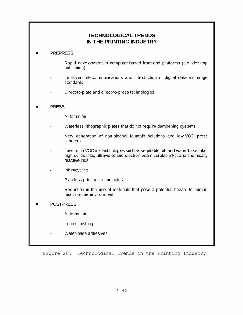
2-92
TECHNOLOGICAL TRENDSIN THE PRINTING INDUSTRY
! PREPRESS
- Rapid development in computer-based front-end platforms (e.g. desktoppublishing)
- Improved telecommunications and introduction of digital data exchangestandards
- Direct-to-plate and direct-to-press technologies
! PRESS
- Automation
- Waterless lithographic plates that do not require dampening systems
- New generation of non-alcohol fountain solutions and low-VOC presscleaners
- Low- or no VOC ink technologies such as vegetable oil- and water-base inks,high-solids inks, ultraviolet and electron beam curable inks, and chemicallyreactive inks
- Ink recycling
- Plateless printing technologies
- Reduction in the use of materials that pose a potential hazard to humanhealth or the environment
! POSTPRESS
- Automation
- In-line finishing
- Water-base adhesives
Figure 28. Technological Trends in the Printing Industry

2-93
In the following sections, new products, emerging technologies,and other factors affecting the printing industry are explored inmore detail.
A. Trends in Prepress Technology
Prepress technologies made major strides in the late 1980sand early 1990s and rapid progress will continue throughout thecurrent decade. Most of the prepress tasks at both prepress shopsand printers are now performed using a combination of computerhardware and software commonly referred to as a front-end platform(Bruno 1990; SRI 1990).
1. Front-End Platforms (Desktop Publishing)
Front-end platform (FEP) is a term used by theindustry to describe the combination of desktop computer hardware andperipherals and sophisticated software that allow users to create,manipulate, and store text, graphic images, and entire documentsprior to printing. These systems are found not only in the printingindustry but in literally thousands of homes and offices across thecountry. FEPs and desktop publishing will continue to develop andgrow in importance well into mid-decade (SRI 1990).
Using FEPs, the lay person can perform many prepress operationsand produce a high quality copy ready for printing. When usedproperly, a primary benefit of this emerging technology will be asignificant reduction in the cost of producing lay-outs ready for theplate maker. This, in turn, will make it profitable for printers toaccept shorter-run jobs. According to the Graphic Arts TechnicalFoundation (GATF), however, lay persons rarely use FEPs properly whenpreparing materials for printing. Instead their limited knowledge ofthe printing process often creates more work for the printer (Jones1993).
Important new products available for prepress functions include:
o Graphics-oriented Workstations. FEPs, now based largelyon low-cost personal computers, will evolve towardgraphics-oriented workstations running production-levelsoftware. The software will be based on productsoriginally developed for CAD/CAM applications (Bruno 1990;SRI 1990).
o Color Electronic Prepress Systems (CEPS). CEPS provide thecapability to perform complete color page makeup includingcolor balancing and correction. Newer systems will bepriced economically thus reducing the price-per-printed-page. CEPS will be capable of performing integrated text

2-94
and graphics functions in both black and white and color.It will be possible to fully network CEPS with otherdigital equipment including, for example, modems fortelecommunications and directly-driven image carrierpreparation systems (Bruno 1990; SRI 1990).
o Digital Scanners. Lower cost flat-bed scanners areexpected to largely replace the drum scanners in newsystems by 1994. These systems use charge-coupled device(CCD) technology as the primary imaging element. Flat-bedscanners will be used in both color and black and whitework and will be capable of scanning a complete page at atime. These systems will be driven by either personalcomputers, graphics workstations, or CEPS. Initially, thecost of these systems will be high, but will probablydecline to levels affordable to the small to medium sizeprint shop by mid-decade (SRI 1990).
2. Telecommunications
According to a report prepared for the Printing 2000Task Force, by 1995 prepress systems will be able to transmit text,graphic images, and even entire documents between different printers'hardware systems (SRI 1990). Already, two ANSI standards for digitaldata exchange in the printing industry have been published and fouradditional standards are under development (Bruno 1990).
Continuing improvements in high-speed/high volumetelecommunications coupled with the growing use of front-endplatforms will lead to the increasing globalization of the printingand publishing industries. More and more frequently customers willuse printers located at great distances or even in foreign countries(SRI 1990).
3. Proofing
The increasing use of telecommunications and localarea networks, coupled with workstations, will result in faster, moreaccurate proofing of materials being readied for the press at asignificant reduction in cost. Remote or "soft" proofing (i.e.,proofing from an electronic medium as opposed to a hardcopy), will beused in initial checking of materials.
During the 1990s it will become possible to produce high-qualitycolor proofs from digital inputs. Advances in digital proofing willbe facilitated by the continuing development of high quality ink-jetprinters to produce color and black-and-white proofs. The ink-jettechnology will be particularly useful to textile houses,architectural firms, and advertisers (SRI 1990).
2-95
4. Direct-to-Plate and Direct-to-Press Technologies
A variety of techniques that allow the directapplication of an image to a printing plate or other image carrierwithout various intermediate steps are under development or justentering commercial use.
Direct-to-plate (or computer-to-plate) technology is expected toplay a major role in offset printing by the mid-1990s. Theintroduction of direct-to-plate processes in offset printing does notrequire additional technological breakthroughs. Instead, it callsfor the integration and refinement of existing technologies. Imagelaser setters are available as are silver and zinc oxide platessufficiently sensitive for use in the direct-to-plate process.Additional refinements required include modification of laser imagesetters to accommodate a wider range of materials, greater laserpower, and increased plate coating sensitivities. These improvementscoupled with photopolymer plates will allow the introduction ofdigital-to-plate technology to traditional commercial printingoperations (SRI 1990). Large and medium size printers are expectedto move rapidly to the use of direct-to-plate technologies. Thetrend will then slow significantly as smaller printers (20 or feweremployees), which account for the majority of printing plants, makethe transition (Purcell).
In addition to direct-to-plate technologies, direct-to-press (orcomputer-to-press) systems are now becoming available. In thesesystems, computer controlled equipment allow the application of theimage directly to the printing cylinder while the cylinder is mountedon the press. For example, Heidelberg USA has a press that includesan imaging system that will create a waterless plate directly on thepress unit. The use of this and similar systems are reported toresult in major reductions in plate preparation time as well as pressdowntime (Petersen 1992).
By the mid-1990s, as much as 7 percent of all printed materialwill be produced using direct-to-plate systems. Some industryanalysts expect this to increase to as much as 50 percent by 2000(SRI 1990). However, as noted above, other analysts are lessoptimistic because they expect the transition to direct-to-platetechnology to be slow among the large number of small printers(Purcell).

2-96
B. Trends in Press Technology
1. General Press Trends
a. Inks
The major environmental factor driving thedevelopment of new ink technologies is the need to reduce VOCemissions which are subject to increasingly stringent state andFederal regulations. In response to VOC requirements and otherhealth, safety, and environmental concerns with solvents and pigmentsystems, new and improved vegetable oil-based and water-based inkswill appear during the 1990s and currently available ultraviolet andelectron-beam curable inks will be widely used by all the majorprinting technologies. In general, the new inks will resistsmearing, emit fewer volatile organic compounds, and make the use ofcolor in new markets possible (Bruno 1990; SRI 1990).
Inks based on soybean oil are increasingly popular in the U.S.,where they are currently used mainly in nonheatset web offsetprinting. In 1987, five newspapers were experimenting with soy-basedinks in the U.S.; by 1990 these inks were being used by over 1,000newspapers. Newspapers use primarily color soy-based inks, replacinginks based on petroleum distillates (Bruno 1990).
Water-based inks generally contain small amounts of solvents,typically an alcohol. Water-based screen printing inks, however, donot contain alcohols. Although water-based inks are now usedprimarily in flexographic and gravure packaging printing, their useis spreading to other areas of printing except lithography. Water-based inks can not be used in lithographic printing because theprocess depends on the affinity of the image area of the plate foroil-based inks and of the non-image area for water (Branco; Centaur;Kinter 1993; SRI 1990).
Another approach being taken by industry in reducing VOCs is theuse of high solids ink, particularly for certain products printedusing heatset lithography. By increasing the solids (i.e., pigmentand/or resin) content of the ink, the solvent level can be reducedfrom as much as 45 percent by weight to 30 percent (Centaur; McGraw-Hill).
A number of no-solvent technologies that emit no VOCs are alsoavailable including ultraviolet (UV) and electron beam (EB) curableinks. UV and EB inks polymerize or "cure" upon exposure to theenergy source indicated by their names. In general these inksconsist of an oligomer, a reactive diluent (usually a multifunctionalacrylate), and a pigment. UV inks also require a photoinitiator. Anumber of health risks are associated with exposure to themultifunctional acrylates found in these inks. UV and EB inks aregenerally more expensive than conventional inks and the capital costs

2-97
of the curing equipment is high. However, the curing systems usemuch less energy than the drying systems often required forconventional inks. Additionally, UV and EB inks dry almostinstantaneously so their use can increase productivity. These inksprovide high gloss print that is both chemical and abrasionresistant. UV and EB inks are used in lithography, screen printing,letterpress, and flexography (Centaur; GCIU; McGraw-Hill; SRI 1990).
Another no-solvent technology is chemically reactive inks.Typically, these are two component systems that polymerize uponmixing. To date, however, chemically reactive inks have found onlyvery limited commercial use (McGraw-Hill).
b. Dampening Systems
Since the 1950s, isopropyl alcohol (IPA) has beenwidely used in fountain solutions for dampening systems onlithographic presses. However, due to increasingly strict state andFederal control of VOCs, the trend is towards the use of alcohol-freefountain solutions. Glycol ethers have been the primary replacementfor alcohols in fountain solutions. 2-Butoxy ethanol, a glycolether, is currently the major substitute for IPA; however, its userequires process changes (Branco; Petersen 1991).
Another alternative is waterless plates that do not require theuse of dampening systems. Waterless plates are discussed in moredetail in section IV.B.2.a of this report.
c. Press Cleaners
Currently, there are three primary categories ofpress cleaners: chlorinated solvents, aromatic petroleumdistillates, and aliphatic petroleum distillates. Potentialsubstitutes include: 2-butoxy ethanol; N-methylpyrrolidone; D-limonene; and low vapor pressure mixtures of aliphatic and aromaticpetroleum distillates (Branco). Others consist of surfactants,surfactant and solvent mixtures, or non-volatile oils such asvegetable oil (Hicks; Petersen 1991).
Traditionally, presses have been cleaned manually. Today,however, automatic press cleaning systems are widely available.Compared to manual cleaning of presses, these systems shorten pressdown-time and reduce (though do not eliminate) solvent use (Hicks).
Most newspapers now use dry-type (i.e., solventless) automaticblanket washers. According to industry sources, while dry systems donot clean as well as manual or automatic systems using solvents, theyare viable substitutes (Hicks).

2-98
d. Process Color
Process color techniques allow the creation ofvirtually any color by overprinting some combination of translucentinks of only four colors: cyan, magenta, yellow, and black.Improvements in turnaround time and quality will cause the use ofprocess color to grow in the 1990s. This growth will be fed by thecontinued preference of consumers for color images in dailynewspapers and news magazines. Other factors include: technologicaldevelopments that allow economies in short-run offset color printing,new prepress systems for processing color images, and theavailability of acceptable quality from laser printers and colorcopiers. Other factors that will contribute to the growth of processcolor including: the development of water-based and vegetable oil-based inks suitable for use in all major printing processes and theintroduction of integrated prepress systems that simplify thepreparation of color pages and reduce color processing costs (SRI1990).
2. Offset Printing
In the 1990s, there are expected to be modestimprovements in offset platemaking and ink technology. The majortrend in lithographic printing, however, will be in the automation ofprinting press operations (SRI 1990).
Microcomputer technology will be employed in the areas of datacollection and process control. Microcomputers now available run atthe speeds required to monitor and adjust the operation of high-speedpresses. Furthermore, extremely sensitive and responsive sensors arenow available that are capable of monitoring the performance ofprinting presses in real-time. These two technologies have beenintegrated to create closed-loop control systems that can monitor andcontrol nearly every aspects of the modern high-speed press (SRI1990).
During the 1990s, the increasing application of automation tooffset printing will increase speed, reduce waste and improve qualityas well as reduce labor requirements. Areas where automatedmonitoring or control are either being implemented or studied include(SRI 1990):
o Plate changing and unloading;
o Paper roll replacement;
o Inking control;
o Temperature control of inks, water, press dryers, and chillrollers;
2-99
o Registration;
o Paper speed and tension control;
o Press cleaning;
o Web tear detection; and
o In-line finishing.
Waterless plates, an important development in lithographicplates, are discussed below. Other changes in offset technology willinclude modest improvements in plate technology, including thecommercial introduction of laser-exposed plates and wider pressesthat will allow faster printing speeds (2500 to 3000 feet per minute)and signatures of up to 72 pages (SRI 1990).
a. Waterless Plates
Waterless plates are a type of lithographic platethat requires no water to prevent the non-image areas of the platefrom accepting ink. The non-image areas of waterless plates arecoated with silicone rubber which has such low surface energy that itwill not be wet by ink. However, early waterless plates, introducedin the U.S. in 1970, had poor scratch resistance and durability.Furthermore, they were sensitive to heat, and elevated temperaturescaused toning of non-image areas. These plates were withdrawn fromthe market in 1977. A second generation of plates was introduced inJapan in the late 1970s that largely overcame these problems. Todaywaterless plates are in widespread use in Japan and are beginning toachieve commercial acceptance in the U.S. (Bruno 1990; Stanilus).
Waterless plates require the use of special waterless inks basedon high viscosity modified phenolic or modified hydrocarbon resinsand high boiling point nonaromatic or alpha-olefin hydrocarbonsolvents. The inks are higher viscosity than conventional offsetinks. Because of their special rheological properties, the inks needto be maintained within a narrow range of temperatures duringprinting. For this reason presses using waterless plates must beequipped with chillers (cooling systems) or printers must stock avariety of inks designed for use under different temperatureconditions (Lustig and Stanulis). Cooling systems are optional onmost new presses and retrofitting of existing units is usuallypossible (Toray).
There are disadvantages to using waterless plates: the platesare more expensive and less durable than conventional lithographicplates and processors for waterless plates run about $40,000. Theinks used are also more expensive. Furthermore, chillers for pressesusing waterless plates cost between $60,000 and $100,000 (American

2-100
Printer and Branco). This technology has increased energyrequirements over traditional technology. Plate and ink chemistrydifferences also need to be examined (Kalima 1993).
From an environmental and health and safety standpoint, theadvantage of waterless plates is they do not require dampening and,therefore, print without the alcohol and other chemicals used indampening systems (Stanilus). However, the plate developingchemistry is solvent based (Jones 1993).
3. Rotogravure Printing
A steady decrease in the time required for cylinderpreparation as well as increasing automation will keep rotogravurecompetitive with both lithographic offset and flexographic printing.
Historically, the major disadvantage of the gravure process incomparison to other printing processes has been the substantiallygreater amount of time required for cylinder preparation. Automationand the development of a number of direct-to-cylinder preparationtechniques have reduced the time required for cylinder preparation;however, gravure still remains uneconomical for smaller press runs.The minimum number of impressions is usually dictated by economicsand the type of product. U.S. publication gravure printers seldomprint below 500,000 copies while in other parts of the worldpublication print orders of 100,000 to 200,000 copies are notuncommon. On the other hand, a specialty gravure (i.e., wallcovering) run may total only a few hundred yards of printed material(Tyszka 1993).
During the 1990s, a number of direct-to-cylinder techniquescurrently either under development or in the early stages ofcommercialization promise to decrease gravure cylinder preparationtime significantly. For example, a computer-to-cylinder system thatuses a laser to carve cells in a polymer coated gravure cylinder hasrecently been installed in a number of U.S. printing plants. Germancompanies are leading in the development of photopolymer cylindersfor gravure presses (Adams 1988; Bruno 1990; SRI 1990).
Automation of rotogravure presses will occur at a slower ratethan for offset presses due primarily to the very large size ofrotogravure presses. However, widespread automation of cylinderchangeover and of paper roll transport and loading has alreadyoccurred. The introduction of fully automated presses controlled bya single operator is expected by the late 1990s (Bruno 1990; SRI1990).
A number of other significant changes are anticipated inrotogravure printing during the next few years. Special polymers andother new materials will partially replace copper and steel in

2-101
cylinders thereby reducing weight and making higher press operatingspeeds possible. Although gravure remains heavily dependent onsolvent-base inks, a growing amount of water-based and ultraviolet-curable inks will be used; however, acceptable water-basedpublication gravure inks have yet to be identified. Wider presseswill be introduced, allowing increased output (Bruno 1990; Jones1993; SRI 1990).
4. Flexographic Printing
Important improvements will occur in both flexographicplates and inks. The use of photopolymers in plate manufacture willboth lower the cost and improve the quality of flexographic plates.Edge sharpness will improve approaching that achieved with offset.Improvements in the density and consistency of the water-based colorinks used in flexography are also expected (SRI 1990).
A major problem in flexographic printing has been so-calledplate or image plugging. However, this problem will be largelyovercome as a result of improved wash-up devices and inking systems.This will result in black-and-white halftone quality approaching thatachieved with offset printing (SRI 1990).
Continuing improvements in process color printing by flexographywill make the process increasingly competitive with lithography inthe medium-quality magazine market (Bruno 1990).
5. Plateless Printing
A variety of plateless technologies are currently inuse. These processes, expected to undergo continuing improvementsand refinements during the 1990s, include: electronic printing; ink-jet printing; thermal printing; ion deposition printing; andmagnetography. Anticipated market trends for these processes arediscussed below. The technologies themselves are described inSection III.F.2 of this report.
Plateless technologies are currently important primarily in theoffice, in-plant, and quick printing markets. They are alsoimportant in direct mailing and personalized advertising. Thesemarkets are expected to be the growth leaders in the printingindustry during the 1990s. As plateless technologies improve andbecome widely available, a growing share of the business that wouldformerly have been done by small- to medium-size commercial printersusing traditional technologies will instead be done in the office orat the quick printer (Bruno 1990; SRI 1990).
In 1990, plateless processes accounted for only about threepercent of the total value of the output of the U.S. printing market.However, these processes' market share will grow explosively in the

2-102
next 35 years, accounting for 11 percent of the market by the year2000 and 21 percent by 2025 (Bruno 1990).
a. Electronic Printing
Electronic printing is used primarily for short-run office, in-plant, and quick printing. Quick printing is expectedto be one of the fastest growing segments of the printing industry inthe foreseeable future and its growth will be fueled in part by thecontinuing increase in the quality and economy of electronic printingtechnologies (SRI 1990). For example, there have been dramaticimprovements in the quality of color copiers. These copiers are soonexpected to be competitive with traditional printing methods in theshort-run (500 to 10,000 copies) color market (GATF 1992a).
Laser printers, connected to personal computers in both theoffice and home environments, will become widespread. Currently,prices are falling and low-end laser printers are available for aslittle as $600. More sophisticated printers capable of using thePostscript page definition language are available for well under$2,000 (SRI 1990).
Use of high dot-density color electrophotography machines withdot densities ranging from 400 dots per inch (DPI) to 2000 DPI willbecome more widely used in the office, in-plant, and fast-servicesenvironments. The quality of the printed output will increaseduring the 1990s but printing speed will continue to be very slowwhen compared to other methods (SRI 1990).
Another growth area for electronic printing is in the productionof relatively inexpensive proof copies of printed materials that willbe printed using one of the traditional printing technologies (Adams1988; Bruno 1990).
b. Ink-jet Printing
Continued technological improvements willstimulate the increased use of ink-jet printers in the printingindustry. The ink-jet printer's speed in addressing and printingvariable information on repetitive forms is credited withrevolutionizing the direct mailing business as well as personalizeddirect mail advertising (Adams 1988; Bruno 1990). The principle usefor this technology, however, is expected to remain in the officeenvironment. Ink-jet printers fall between dot-matrix and laserprinters both in cost and quality of printed output. However, ink-jet printers have the capability to produce both graphics and text ina variety of colors on plain paper and transparencies. Thesecapabilities will ensure broadening use in the office environment forengineering graphics and other business applications. Higher quality

2-103
color ink-jet printers will be developed in response to the growingamount of sophisticated graphics software available for personalcomputers (SRI 1990).
c. Thermal Printing
Thermal printers will continue to enjoy a limitedincrease in market share during the 1990s. This growth will bestimulated by improvements in resolution, color capability, andreduced paper cost. However, a number of drawbacks remain, includingthe need for special papers, a low rate of output, and, despiteimprovements, comparatively poor image quality. Thermal printing iscurrently used in facsimile machines and other office applications(SRI 1990).
d. Ion Deposition
Ion deposition printing, an emerging technologysimilar to electronic printing and other electrostatic processes,will show marked improvement during the mid-1990s. Currently, thistechnology is used primarily in the office environment where it isused to print forms, reports, and other business documents. One areawhere this technology is expected to be applied in the 1990s is inmultiple-color printing. However, ion deposition printing willrequire considerable development and refinement before it can competewith laser printing (Bruno 1990; SRI 1990).
e. Magnetography
Magnetography is similar to electronic printingexcept that a magnetic, and not an electrostatic, photoconductor isused. The use of magnetography is limited to a few specialtyprinting markets such as printing identifier labels, bar codes,pressure sensitive labels, and glossy substrates. No majorimprovements in this technology are expected in the 1990s.Furthermore, due to shortcomings such as slow speed, high tonercosts, and the inability to do color process printing little or nomarket growth is anticipated (SRI 1990).
C. Postpress Technology
Until recently the automation of postpress operations hasbeen limited, and, for many printers, postpress operations remainlabor intensive. One source estimates that nearly 80 percent of thecost of some print jobs is material handling. Because much of thelabor in postpress operations involves materials handling, there is

2-104
the opportunity to decrease postpress costs substantially throughfurther automation (Bruno 1990; SRI 1990).
The major development in postpress technology has been theintroduction of computer-controlled in-line finishing systems thatdirectly link the press with postpress operations. In comparison tooff-line finishing, these in-line systems can typically finish threeto four times the number of units per hour with roughly half thepersonnel (Adams 1988; SRI 1990).
In addition to traditional binding and finishing operations,some in-line finishing systems can perform a number of specializedoperations such as addressing and demographic binding. Demographicbinding refers to the selective assembly of a publication based onany of several factors including geographic area, family structure,income, or interests. The technique can be used, for example, toinclude advertisements only in those copies of a magazine that willbe received by persons in the advertisers selling area (Adams 1988). Selective binding techniques used to target printed products toselected geographic areas and markets are widely used today and havebeen proven to be very effective marketing tools. The use of thistechnology will continue to expand at a rapid rate due, primarily,to the intense interest shown by advertising agencies and otherdirect marketing organizations (Bruno 1990; SRI 1990).
Water-based adhesives have long been used in printing facilitiesoperations. However, an important chemical trend in postpressoperations is the increasing use water-based adhesives in place ofsolvent-based adhesives containing toluene and methyl ethyl ketone.
During the 1990s, the introduction of robots for postpressmaterials tracking and handling is anticipated (Bruno 1990).
R-1
REFERENCES
Adams, J. Michael, et. al. 1988. Printing Technology, 3rd ed.Albany, NY: Delmar Publishers, Inc.
A.F. Lewis. 1991. Blue Book Marketing Information Reports: GraphicArts Industry Analysis by Plant Size, Equipment, Product Specialties.New York, NY: A.F. Lewis & Co., Inc.
American Printer. 1991. "Running On Empty: Waterless PrintingBoasts Quality and Ease of Operation for Some Printers." AmericanPrinter. August. pp. 46 - 48.
BOC. 1990a. U.S. Department of Commerce, Bureau of the Census.1987 Census of Manufactures, Industry Series - Newspapers,Periodicals, Books, and Miscellaneous Publishing (Industries 2711,2721, 2731, 2732, and 2741). Washington, DC: Government PrintingOffice. Publication No. MC87-I-27A.
BOC. 1990b. U.S. Department of Commerce, Bureau of the Census. 1987Census of Manufactures, Industry Series - Commercial Printing andManifold Business Forms (Industries 2752, 2754, 2759, and 2761).Washington, DC: Government Printing Office. Publication No. MC87-I-27B.
BOC. 1990c. U.S. Department of Commerce, Bureau of the Census. 1987Census of Manufactures, Industry Series - Greeting Cards;Bookbinding; Printing Trade Services (Industries 2771, 2782, 2789,2791, and 2796). Washington, DC: Government Printing Office.Publication No. MC87-I-27C.
BOC. 1993. U.S. Department of Commerce, Bureau of the Census. 1987Annual Survey of Manufactures: Geographic Area Statistics.Washington, DC: Government Printing Office. Publication No.M91(AS)-3.
Branco, Dolores M., et. al. 1991. A Guide to Pollution Preventionfor Sheet-fed Offset Lithographers. Tufts University Department ofCivil Engineering, Medford, MA. Prepared for the Printing Industriesof New England. August.
Bruno, Michael H. 1990. Michael H. Bruno's Status of Printing, 1989- 90: A State-of-the-Art Report. Salem, NH: GAMA Communications.
Bruno, Michael H. 1991. Michael H. Bruno's Status of Printing, 1991Update: A State-of-the-Art Report. Salem, NH: GAMA Communications.

R-2
REFERENCES (continued)
Buonicore, Anthony J. and Wayne T. Davis, editors. 1992. AirPollution Engineering Manual, Chapter 11, "Graphic Arts Industry."Air & Waste Management Association. Van Nostrand Reinhold, New York,NY. pp. 371-400.
Centaur. 1984. Economic Profile of the Printing Ink Industry (SIC2893). Final Report. Centaur Associates, Inc., Washington, DC.Prepared for the U.S. EPA under contract no. 68-01-6412, task orders83-08 and 84-13. August 24.
DeJidas, Jr., Lloyd P. 1992. "Alcohol Substitutes: Making ThemWork for You." GATFWORLD. Graphic Arts Technical Foundation,Pittsburgh, PA. Vol. 4, No. 1. p. 21
Field, Janet N. (ed.). 1980. Graphic Arts Manual. New York, NY:Arno Press, Musarts Publishing Corp.
GAA. 1989. Profile Survey of the U.S. Gravure Industry. GravureAssociation of America, New York, NY. p. INTRO-15.
GAA. 1991. Gravure Process and Technology. Gravure Association ofAmerica, Rochester, NY.
GAM. 1991. "GAM 101 Official Industry Ranking of the Top PrintingFirms." Graphic Arts Monthly. August.
GATF. 1992a. "1992 Technology Forecast." Graphic Arts TechnicalFoundation, Pittsburgh, PA. pp. 9-10
GATF. 1992b. C. Nelson Ho. "Printing Industry and Its ChemicalUsage" and "Chemicals Used in the Printing Industry." Graphic ArtsTechnical Foundation, Pittsburgh, PA. (Work performed under contractto Mathtech, Inc., Falls Church, VA).
GCIU. no date. "Ultraviolet Inks and Coatings," GraphicsCommunications International Union. Produced through a grant fromthe New York State Safety and Health Training and Education Programunder Contract No. C005455.
Hawley, Gessner G. (ed.). 1981. The Condensed Chemical Dictionary,10th ed. New York, NY: Van Nostrand Reinhold Co.
Hicks, Jennifer. 1991. "A Clean Sweep: Reduced Makeready, PrintQuality Guide Move to Automatic Blanket Washers." American Printer.August. pp. 34 - 36.

R-3
REFERENCES (continued)
Jones. 1993. Letter with comments on the draft Use Cluster Analysisof the Printing Industry from Gary A. Jones, Manager, Office ofEnvironmental Information, Graphic Arts Technical Foundation,Pittsburgh, PA to Susan Krueger, U.S. Environmental ProtectionAgency, Washington, DC. October 5.
Kalima. 1993. Letter with comments on the draft Use ClusterAnalysis of the Printing Industry from Dale G. Kalima, EnvironmentalSupervisor, R.R. Donnelley & Sons Co., Lisle, IL to Susan Krueger,U.S. Environmental Protection Agency, Washington, DC. October 12.
Kinter. 1992. Personal communication between Marcia Kinter, ScreenPrinting Association International, Fairfax VA and Patrick Godfrey,Mathtech, Inc., Falls Church, VA, February.
Kinter. 1993. Comments on the draft Use Cluster Analysis of thePrinting Industry. Marcia Kinter, Screen Printing AssociationInternational, Fairfax, VA. September 28.
Kirk-Othmer. 1982. Bruno, MH. "Printing Processes." In: Kirk-Othmer Encyclopedia of Chemical Technology, 3rd ed., vol. 19. NewYork, NY: Wiley-Interscience. pp. 110 - 163.
Lewis. 1992. Personal communication between Timothy Lewis, A.F.Lewis & Co., Inc., New York, NY. and Patrick Godfrey, Mathtech, Inc.,Falls Church, VA, February.
Lustig, Theodore. 1990. "Waterless Offset Inks." Graphic ArtsMonthly. December. pp. 108+.
McGraw-Hill. 1987. Bruno, MH. "Printing." In: McGraw-HillEncyclopedia of Science and Technology, 6th ed., vol. 14. New York,NY: McGraw-Hill, Inc. pp. 276 - 314.
Petersen, Debbie. 1991. "A Delicate Balance: Weighing the Meritsof Replacing High-VOC Chemicals With "Friendly" Substitutes to SlashAir Emissions." American Printer. August. pp. 26 - 30.
Petersen, Debbie. 1992. "The State of the Plates." AmericanPrinter. February. pp. 26 - 29.
Purcell. 1993. Comments on the draft Use Cluster Analysis of thePrinting Industry. Thomas Purcell, Printing Industries of America,Alexandria, VA.
Quick Printing. 1991. "Quick Printing Top 100: Slow Growth, RecordSales." Quick Printing. June.

R-4
REFERENCES (continued)
Screen Printing. 1990. "Screen Printing 100." Screen Printing.November.
SIC. 1987. Standard Industrial Classification Manual, 1987. Washington, DC: Government Printing Office. Publication No. PB87-100012. pp. 126 - 131.
SPAI. 1991. Industry Profile Study. Fairfax, VA: Screen PrintingAssociation International.
SRI. 1993. "Printing Inks (Worldwide)." In: Specialty Chemicals.SRI International, Menlo Park, CA. January.
SRI. 1990. Printing 2000. Prepared by SRI International, MenloPark, CA for the Printing 2000 Task Force, Printing Industries ofAmerica, Alexandria, VA. SRI Project 7656. August.
Stanilus, Catherine. 1990. "The Toray Waterless Plate System."High Volume Printing. February. pp. 50 - 51.
Toray. No date [1991]. "Toray Waterless Plate." Toray Industries,Inc., Japan.
Tyszka. 1993. Letter with comments on the draft Use ClusterAnalysis of the Printing Industry from Gregory Tyszka, Vice PresidentTechnical Services, Gravure Association of America, Rochester, NY toSusan Krueger, U.S. Environmental Protection Agency, Washington, DC.October 12.
USIO. 1992. U.S. Department of Commerce, International TradeAdministration. 1992 U.S. Industrial Outlook, Section 25, "Printingand Publishing." Washington, DC: Government Printing Office.
USIO. 1993. U.S. Department of Commerce, International TradeAdministration. 1993 U.S. Industrial Outlook, Section 24, "Printingand Publishing." Washington, DC: Government Printing Office.