part 56—piping systems and appurtenances - …€¦ · · 2018-03-1656.01–2 incorporation by...
TRANSCRIPT

157
Coast Guard, DOT Pt. 56
supporting structure shall be analyzedto verify its adequacy.
(b) In all cases where the tanks aremechanically stress relieved in place inthe ship or barge and the tanks are de-signed to carry cargoes with a specificgravity less than 1.05, the ship or bargeshall be shown to have adequate stabil-ity and buoyancy, as well as strengthto carry the excess weight of the tankduring the stress relief procedure.
PART 56—PIPING SYSTEMS ANDAPPURTENANCES
Subpart 56.01—General
Sec.56.01–1 Scope (replaces 100.1).56.01–2 Incorporation by reference.56.01–3 Power boiler external piping (Re-
places 100.1.1, 100.1.2, 111.6, 122.1, 132 and133).
56.01–5 Adoption of ANSI (American Na-tional Standards Institute) Code B31.1 forpressure and power piping, and otherstandards.
56.01–10 Plan approval.
Subpart 56.04—Piping Classification
56.04–1 Scope.56.04–2 Piping classification according to
service.56.04–10 Other systems.
Subpart 56.07—Design
56.07–5 Definitions (modifies 100.2).56.07–10 Design conditions and criteria
(modifies 101—104.7).
Subpart 56.10—Components
56.10–1 Selection and limitations of pipingcomponents (replaces 105 through 108).
56.10–5 Pipe.
Subpart 56.15—Fittings
56.15–1 Pipe joining fittings.56.15–5 Fluid-conditioner fittings.56.15–10 Special purpose fittings.
Subpart 56.20—Valves
56.20–1 General.56.20–5 Marking (reproduces 107.2).56.20–7 Ends.56.20–9 Valve construction.56.20–15 Valves employing resilient mate-
rial.56.20–20 Valve bypasses.
Subpart 56.25—Pipe Flanges, Blanks,Flange Facings, Gaskets, and Bolting
56.25–5 Flanges.56.25–7 Blanks.56.25–10 Flange facings.56.25–15 Gaskets (reproduces 108.4).56.25–20 Bolting.
Subpart 56.30—Selection and Limitations ofPiping Joints
56.30–1 Scope (replaces 110 through 118).56.30–3 Piping joints (reproduces 110).56.30–5 Welded joints.56.30–10 Flanged joints (modifies 104.5.1 (a)).56.30–15 Expanded or rolled joints.56.30–20 Threaded joints.56.30–25 Flared, flareless, and compression
fittings.56.30–27 Caulked joints.56.30–30 Brazed joints.56.30–35 Gasketed mechanical couplings.56.30–40 Flexible pipe couplings of the com-
pression or slip-on type.
Subpart 56.35—Expansion, Flexibility andSupports
56.35–1 Pipe stress calculations (replaces119.7).
56.35–10 Nonmetallic expansion joints (re-places 119.5.1).
56.35–15 Metallic expansion joints (replaces119.5.1).
Subpart 56.50—Design RequirementsPertaining to Specific Systems
56.50–1 General (replaces 122.6 through122.10).
56.50–10 Special gaging requirements.56.50–15 Steam and exhaust piping.56.50–20 Pressure relief piping.56.50–25 Safety and relief valve escape pip-
ing.56.50–30 Boiler feed piping.56.50–35 Condensate pumps.56.50–40 Blowoff piping (replaces 102.2.5 (d)).56.50–45 Circulating pumps.56.50–50 Bilge and ballast piping.56.50–55 Bilge pumps.56.50–57 Bilge piping and pumps, alternative
requirements.56.50–60 Systems containing oil.56.50–65 Burner fuel-oil service systems.56.50–70 Gasoline fuel systems.56.50–75 Diesel fuel systems.56.50–80 Lubricating-oil systems.56.50–85 Tank-vent piping.56.50–90 Sounding devices.56.50–95 Overboard discharges and shell con-
nections.56.50–96 Keel cooler installations.56.50–97 Instrument, control and sampling
piping (modifies 122.3).56.50–105 Low-temperature piping.
VerDate 27-NOV-96 08:03 Dec 23, 1996 Jkt 167174 PO 00000 Frm 00157 Fmt 8010 Sfmt 8010 E:\CFR\167174.035 167174
158
46 CFR Ch. I (10–1–96 Edition)§ 56.01–1
56.50–110 Diving support systems.
Subpart 56.60—Materials
56.60–1 Acceptable materials and specifica-tions (replaces 123 and Table 126.1 inANSI–B31.1).
56.60–2 Limitations on materials.56.60–3 Ferrous materials.56.60–5 Steel (High temperature applica-
tions).56.60–10 Cast iron and malleable iron.56.60–15 Ductile iron.56.60–20 Nonferrous materials.56.60–25 Nonmetallic materials.
Subpart 56.65—Fabrication, Assembly andErection
56.65–1 General (replaces 127 through 135.4).
Subpart 56.70—Welding
56.70–1 General.56.70–3 Limitations.56.70–5 Material.56.70–10 Preparation (modifies 127.3).56.70–15 Procedure.56.70–20 Qualification, general.
Subpart 56.75—Brazing
56.75–5 Filler metal.56.75–10 Joint clearance (reproduces 128.2.2).56.75–15 Heating (reproduces 128.2.3).56.75–20 Brazing qualification.56.75–25 Detail requirements.56.75–30 Pipe joining details.
Subpart 56.80—Bending and Forming
56.80–5 Bending.56.80–10 Forming (reproduces 129.2).56.80–15 Heat treatment of bends and formed
components.
Subpart 56.85—Heat Treatment of Welds
56.85–5 Heating and cooling method (repro-duces 131.1).
56.85–10 Preheating.56.85–15 Postheat treatment.
Subpart 56.90—Assembly
56.90–1 General.56.90–5 Bolting procedure.56.90–10 Threaded piping (reproduces 135.4).
Subpart 56.95—Inspection
56.95–1 General (replaces 136).56.95–5 Rights of access of marine inspec-
tors.56.95–10 Type and extent of examination re-
quired.
Subpart 56.97—Pressure Tests
56.97–1 General (replaces 137).56.97–5 Pressure testing of nonstandard pip-
ing system components.56.97–25 Preparation for testing (Reproduces
137.3).56.97–30 Hydrostatic tests (Reproduces
137.4).56.97–35 Pneumatic tests (Replaces 137.5).56.97–38 Initial service leak test (Repro-
duces 137.7).56.97–40 Installation tests.
AUTHORITY: 33 U.S.C. 1321(j), 1509; 43 U.S.C.1333; 46 U.S.C. 3306, 3703; E.O. 12234, 45 FR58801, 3 CFR, 1980 Comp., p. 277; E.O. 12777, 56FR 54757, 3 CFR, 1991 Comp., p. 351; 49 CFR1.46.
SOURCE: CGFR 68–82, 33 FR 18843, Dec. 18,1968, unless otherwise noted.
Subpart 56.01—General
NOTE: See § 50.15–10 for general adoption ofstandards of the ANSI (American NationalStandards Institute). The printing of por-tions of the ‘‘American National StandardCode for Pressure Piping, Power Piping,’’ANSI–B31.1, is with the permission of thepublisher, The American Society of Mechani-cal Engineers, United Engineering Center,345 East 47th Street, New York, N.Y. 10017.The adoption of this standard ANSI–B31.1 forpressure piping and power piping is subjectto specific limitations or modifications asdescribed in this part. Those requirements inANSI–B31.1 which are not referred to in thispart are adopted without change. Table56.01–5(a) sets forth a general reference tovarious paragraphs in ANSI–B31.1 which arelimited, modified, or replaced by regulationsin this part.
§ 56.01–1 Scope (replaces 100.1).
(a) This part contains requirementsfor the various ships’ and barges’ pip-ing systems and appurtenances.
(b) The respective piping systems in-stalled on ships and barges shall havethe necessary pumps, valves, regula-tion valves, safety valves, relief valves,flanges, fittings, pressure gages, liquidlevel indicators, thermometers, etc.,for safe and efficient operation of thevessel.
(c) Piping for industrial systems onmobile offshore drilling units need notfully comply with the requirements of
VerDate 27-NOV-96 08:03 Dec 23, 1996 Jkt 167174 PO 00000 Frm 00158 Fmt 8010 Sfmt 8010 E:\CFR\167174.036 167174

159
Coast Guard, DOT § 56.01–2
this part but must meet Subpart 58.60of this subchapter.
[CGFR 68–82, 33 FR 18843, Dec. 18, 1968, asamended by CGD 73–251, 43 FR 56799, Dec. 4,1978]
§ 56.01–2 Incorporation by reference.(a) Certain standards and specifica-
tions are incorporated by referenceinto this part with the approval of theDirector of the Federal Register in ac-cordance with 5 U.S.C. 552(a). To en-force any edition other than the onelisted in paragraph (b) of this section,notice of the change must be publishedin the FEDERAL REGISTER and the ma-terial made available to the public. Allapproved material is on file at the Of-fice of the Federal Register, 800 NorthCapitol Street, NW., suite 700, Wash-ington, DC, and is available from thesources indicated in paragraph (b).
(b) The standards and specificationsapproved for incorporation by ref-erence in this part, and the sections af-fected are:American National
Standards Institute(ANSI); 11 West 42ndStreet, New York, NY10036:
ANSI B1.1–82 UnifiedInch Screw Threads(UN and UNRThread Form).
56.60–1; 56.25–20
ANSI B1.20.1–83 PipeThreads, GeneralPurpose (Inch).
56.60–1
ANSI B1.20.3–76 (re-affirmed 1982)Dryseal PipeThreads (Inch).
56.60–1
ANSI B16.1–75 CastIron Flanges andFlanged Fittings,Class 25, 125, 250 and800.
56.60–1; 56.60–10
ANSI B16.3–85 Malle-able Iron ThreadedFittings, Classes 150and 300.
56.60–1
ANSI B16.4–85 CastIron Threaded Fit-tings, Classes 125and 250.
56.60–1
ANSI B16.5–81 PipeFlanges andFlanged Fittings.
56.25–20;56.30–10; 56.60–1
ANSI B16.9–86 Fac-tory-Made WroughtSteel ButtweldingFittings.
56.60–1
ANSI B16.10–86 Face-to-Face and End-to-End Dimensions ofFerrous Valves.
56.60–1
ANSI B16.11–80Forged Steel Fit-tings, Socket-Weld-ing and Threaded.
56.30–5; 56.60–1
ANSI B16.14–83 Fer-rous Pipe Plugs,Bushings, and Lock-nuts with PipeThreads.
56.60–1
ANSI B16.15–85 CastBronze ThreadedFittings, Classes 125and 250.
56.60–1
ANSI B16.18–84 CastCopper Alloy SolderJoint Pressure Fit-tings.
56.60–1
ANSI B16.20–73 Ring-Joint Gaskets andGrooves for SteelPipe Flantion VIII,Division 1, PressureVessels, 1986 withaddenda.
56.15–1; 56.15–5;56.15–10; 56.25–5;56.30–10; 56.30–30;56.60–15; 56.60–1;56.95–10
Section IX, Weld-ing and BrazingQualifications,1986 with ad-denda.
56.70–5; 56.70–20;56.75–20; 56.0–1
ANSI B16.24–79 BronzePipe Flanges andFlanged Fittings,Class 150 and 300.
56.60–1
ANSI B16.25–86 Butt-welding Ends.
56.60–1; 56.30–5;56.70–10
ANSI B16.28–86Wrought SteelButtwelding ShortRadius Elbows andReturns.
56.60–1
ANSI B16.29–86Wrought Copper andWrought CopperAlloy Solder JointDrainage Fittings—DWV.
56.60–1
ANSI B16.34–88Valves-Flanged,Threaded and Weld-ing End.
56.20–1; 56.60–1
ANSI B16.42–87 Duc-tile Iron PipeFlanges andFlanged Fittings,Classes 150 and 300.
56.60–1
ANSI B18.2.1–81Square and HexBolts and Screws,Inch Series.
56.25–20; 56.60–1
ANSI B18.2.2–87Square and HexNuts.
56.25–20; 56.60–1
VerDate 27-NOV-96 08:03 Dec 23, 1996 Jkt 167174 PO 00000 Frm 00159 Fmt 8010 Sfmt 8010 E:\CFR\167174.036 167174
160
46 CFR Ch. I (10–1–96 Edition)§ 56.01–2
ANSI B31.1–86 PowerPiping.
56.01–5
ANSI B36.10M–85Welded and Seam-less Wrought SteelPipe.
56.07–5; 56.30–20;56.60–1
ANSI B36.19M–85Stainless Steel Pipe.
56.07–5; 56.60–1
American Society of Me-chanical Engineers(ASME): United Engi-neering Center, 345 East47th Street, New York,NY 10017:
Boiler and PressureVessel Code:
Section I, PowerBoilers, 1986with addenda.
56.15–5; 56.15–10;56.60–1; 56.60–1;56.70–15; 56.95–1056.15–1
Section VIII, Di-vision 1, Pres-sure Vessels,1986 with ad-denda.
56.15–1; 56.15–5;56.15–10; 56.25–5;56.30–10; 56.30–30;56.60–15; 56.60–1;56.95–10
Section IX, Weld-ing and BrazingQualifications,1986 with ad-denda.
56.70–5; 56.70–20;56.75–20; 56.85–10
American Society forTesting and Materials(ASTM), 1916 RaceStreet, Philadelphia,PA 19103:
ASTM A 36–84a Struc-tural Steel.
56.30–10
ASTM A 47–84 Malle-able Iron Castings.
56.60–1
ASTM A 53–84a Pipe,Steel, Black andHot-Dipped, Zinc-Coated, Welded andSeamless.
56.10–556.60–1
ASTM A 106–84aSeamless CarbonSteel Pipe for High-Temperature Serv-ice.
56.60–1
ASTM A 126–84 GrayIron Castings forValves, Flanges,and Pipe Fittings.
56.60–1
ASTM A 134–80 Pipe,Steel, Electric-Fu-sion (ARC)-Welded(Sizes NPS 16 andover.).
56.60–1
ASTM A 135–84 Elec-tric-Resistance-Welded Steel Pipe.
56.60–1
ASTM A 139–84 Elec-tric-Fusion (Arc)-Welded Steel Pipe(Sizes 4 in. andover).
56.60–1
ASTM A 178–84a Elec-tric-Resistance-Welded CarbonSteel Boiler Tubes.
56.60–1
ASTM A 179–84 Seam-less Cold-DrawnLow-Carbon SteelHeat-Exchanger andCondenser Tubes.
56.60–1
ASTM A 182–84cForged or RolledAlloy-Steel PipeFlanges, ForgedFittings, and Valvesand Parts for High-Temperature Serv-ice.
56.50–105
ASTM A 192–84aSeamless CarbonSteel Boiler Tubesfor High-PressureService.
56.60–1
ASTM A 194–84a Car-bon and Alloy SteelNuts for Bolts forHigh-Pressure andHigh-TemperatureService.
56.50–105
ASTM A 197–79 Cu-pola Malleable Iron.
56.60–1
ASTM A 199–84 Seam-less Cold-Drawn In-termediate Alloy-Steel Heat-Ex-changer and Con-denser Tubes.
56.60–1
ASTM A 210–84aSeamless Medium-Carbon Steel Boilerand SuperheaterTubes.
56.60–1
ASTM A 213–84bSeamless Ferriticand AusteniticAlloy-Steel Boiler,Superheater, andHeat-ExchangerTubes.
56.60–1
ASTM A 214–84a Elec-tric-Resistance-Welded CarbonSteel Heat-Ex-changer and Con-denser Tubes.
56.60–1
ASTM A 226–84a Elec-tric-Resistance-Welded CarbonSteel Boiler andSuperheater Tubesfor High-PressureService.
56.60–1
VerDate 27-NOV-96 08:03 Dec 23, 1996 Jkt 167174 PO 00000 Frm 00160 Fmt 8010 Sfmt 8010 E:\CFR\167174.036 167174
161
Coast Guard, DOT § 56.01–2
ASTM A 234–84a Pip-ing Fittings ofWrought CarbonSteel and AlloySteel for Moderateand Elevated Tem-peratures.
56.60–1
ASTM A 249–84b Weld-ed Austenitic SteelBoiler, Superheater,Heat-Exchanger,and CondenserTubes.
56.60–1
ASTM A 268–84aSeamless and Weld-ed Ferritic Stain-less Steel Tubingfor General Service.
56.60–1
ASTM A 276–84aStainless and Heat-Resisting SteelBars and Shapes.
56.60–2
ASTM A 307–84 Car-bon Steel Exter-nally ThreadedStandard Fasteners.
56.25–20
ASTM A 312–84cSeamless and Weld-ed Austenitic Stain-less Steel Pipe.
56.50–105; 56.60–1
ASTM A 320–84aAlloy-Steel BoltingMaterials for Low-Temperature Serv-ice.
56.50–105
ASTM A 333–84bSeamless and Weld-ed Steel Pipe forLow-TemperatureService.
56.50–105; 56.60–1
ASTM A 334–84bSeamless and Weld-ed Carbon andAlloy-Steel Tubesfor Low Tempera-ture Service.
56.50–105; 56.60–1
ASTM A 335–84aSeamless FerriticAlloy Steel Pipe forHigh-TemperatureService.
56.60–1
ASTM A 350–84a Forg-ings, Carbon andLow-Alloy Steel,Requiring NotchToughness Testingfor Piping Compo-nents.
56.50–105
ASTM A 351–84a SteelCastings, Aus-tenitic, for High-Temperature Serv-ice.
56.50–105
ASTM A 352–84a SteelCastings, Ferriticand Martensitic, forPressure-Contain-ing Parts Suitablefor Low-Tempera-ture Service.
56.50–105
ASTM A 358–84b Elec-tric-Fusion-WeldedAustenitic Chro-mium-Nickel AlloySteel Pipe for High-Temperature Serv-ice.
56.60–1
ASTM A 369–84 Car-bon and FerricAlloy Steel Forgedand Bored Pipe forHigh TemperatureService.
56.60–1
ASTM A 376–84 Seam-less AusteniticSteel Pipe for High-TemperatureCentral-StationService.
56.07–10; 56.60–1;56.60–2
ASTM A 395–80 Fer-ritic Ductile IronPressure-RetainingCastings for Use atElevated Tempera-tures.
56.60–1; 56.50–60;56.60–15
ASTM A 403–84aWrought AusteniticStainless Steel Pip-ing Fittings.
56.60–1
ASTM A 420–84 PipingFittings of WroughtCarbon Steel andAlloy Steel forLow-TemperatureService.
56.50–105; 56.60–1
ASTM A 430–84a Aus-tenitic Steel,Forged and BoredPipe for High-Tem-perature Service.
56.60–1
ASTM A 520–72 Sup-plementary Re-quirements forSeamless and Elec-trical-Resistance-Welded CarbonSteel Tubular Prod-ucts for High-Tem-perature ServiceConforming to ISORecommendationsfor Boiler Construc-tion.
56.60–1
VerDate 27-NOV-96 08:03 Dec 23, 1996 Jkt 167174 PO 00000 Frm 00161 Fmt 8010 Sfmt 8010 E:\CFR\167174.036 167174

162
46 CFR Ch. I (10–1–96 Edition)§ 56.01–2
ASTM A 522–81Forged or Rolled 8and 9% NickelAlloy SteelFlanges, Fittings,Valves, and Partsfor Low-Tempera-ture Service.
56.50–105
ASTM A 575–81 SteelBars, Carbon, Mer-chant Quality, M-Grades.
56.60–2
ASTM A 576–81 SteelBars, Carbon, Hot-Wrought, SpecialQuality.
56.60–2
ASTM B 16–85 Free-Cutting Brass Rod,Bar, and Screw Ma-chines.
56.60–2
ASTM B 21–83b NavalBrass Rod, Bar, andShapes.
56.60–2
ASTM B 26–84 Alu-minum-Alloy SandCastings.
56.60–2
ASTM B 42–84 Seam-less Copper Pipe,Standard Sizes.
56.60–1
ASTM B 43–84 Seam-less Red Brass Pipe,Standard Sizes.
56.60–1
ASTM B 68–83 Seam-less Copper Tube,Bright Annealed.
56.60–1
ASTM B 75–84 Seam-less Copper Tube.
56.60–1
ASTM B 85–84 Alu-minum-Alloy DieCastings.
56.60–2
ASTM B 88–83a Seam-less Copper WaterTube.
56.60–1
ASTM B 96–84a Cop-per Silicon AlloyPlate and Sheet,Strip, and RolledBar for GeneralPurposes and Pres-sure Vessels.
56.60–2
ASTM B 111–85 Copperand Copper-AlloySeamless CondenserTubes and FerruleStock.
56.60–1
ASTM B 124–84 Copperand Copper-AlloyForging Rod, Bar,and Shapes.
56.60–2
ASTM B 154–82 Mer-curous Nitrate Testfor Copper and Cop-per Alloys.
56.60–2
ASTM B 161–81 NickelSeamless Pipe andTube.
56.60–1
ASTM B 165–81 Nick-el-Copper Alloy(UNS N04400) Seam-less Pipe and Tube.
56.60–1
ASTM B 167–80 Nick-el-Chromium-IronAlloy (UNS N06600–N06690) SeamlessPipe and Tube.
56.60–1
ASTM B 171–85a Cop-per-Alloy CondenserTube Plates.
56.60–2
ASTM B 210–82a Alu-minum-AlloyDrawn SeamlessTubes.
56.60–1
ASTM B 234–85 Alu-minum-AlloyDrawn SeamlessTubes for Condens-ers and Heat Ex-changers.
56.60–1
ASTM B 241–83a Alu-minum-Alloy Seam-less Pipe and Seam-less Extruded Tube.
56.60–1
ASTM B 280–83 Seam-less Copper Tube forAir Conditioningand RefrigerationField Service.
56.60–1
ASTM B 283–83b Cop-per and Copper-Alloy Die Forgings(Hot-Pressed).
56.60–2
ASTM B 315–85 Seam-less Copper-AlloyPipe and Tube.
56.60–1
ASTM B 361–81 Fac-tory-Made WroughtAluminum and Alu-minum-Alloy Weld-ing Fittings.
56.60–1
ASTM D 635–81 Rateof Burning and/orExtent and Time ofBurning of Self-Supporting Plasticsin a Horizontal Po-sition.
56.60–25
ASTM D 1785–83Poly(Vinyl Chlo-ride)(PVC) PlasticPipe, Schedules 40,80, and 120.
56.60–25
ASTM D 2241–84Poly(Vinyl Chlo-ride) (PVC) Pres-sure-Rated Pipe(SDR-Series).
56.60–25
ASTM D 2464–76ThreadedPoly(Vinyl Chlo-ride) (PVC) PlasticPipe Fittings,Schedule 80.
56.60–25
VerDate 27-NOV-96 08:03 Dec 23, 1996 Jkt 167174 PO 00000 Frm 00162 Fmt 8010 Sfmt 8010 E:\CFR\167174.036 167174

163
Coast Guard, DOT § 56.01–2
ASTM D 2466–78Poly(Vinyl Chlo-ride) (PVC) PlasticPipe Fittings,Schedule 40.
56.60–25
ASTM D 2467–76aSocket-TypePoly(Vinyl Chlo-ride)(PVC) PlasticPipe Fittings,Schedule 80.
56.60–25
ASTM D 2665–82Poly(Vinyl Chlo-ride) (PVC) PlasticDrain, Waste, andVent Pipe and Fit-tings.
56.60–25
ASTM D 2863–77 Meas-uring the MinimumOxygen Concentra-tion to SupportCandle-Like Com-bustion of Plastics(Oxygen Index).
56.60–25
ASTM E 23–82Notched Bar ImpactTesting of MetallicMaterials.
56.50–105
ASTM F 682–82aWrought CarbonSteel Sleeve-TypePipe Couplings.
56.60–1
ASTM F 1006–86 En-trainment Separa-tors for Use in Ma-rine Piping Applica-tions.
56.60–1
ASTM F 1007–86 Pipe-Line ExpansionJoints of thePacked Slip Typefor Marine Applica-tion.
56.60–1
ASTM F 1020–86 Line-Blind Valves forMarine Applica-tions.
56.60–1
ASTM F 1120–87 Cir-cular Metallic Bel-lows Type Expan-sion Joints for Usein Marine Piping.
56.60–1
ASTM F 1123–87 Non-Metallic ExpansionJoints for Use inMarine Piping Ap-plications.
56.60–1
ASTM F 1139–88Steam Traps andDrains.
56.60–1
ASTM F 1172–88 FuelOil Meters of theVolumetric PositiveDisplacement Type.
56.60–1
ASTM F 1173–88Epoxy Resin Fiber-glass Pipe and Fit-tings to be Used forMarine Applica-tions.
56.60–1; 56.60–25
ASTM F 1199–88 Castand Welded PipeLine Strainers.
56.60–1
ASTM F 1200–88 Fab-ricated (Welded)Pipe Line Strainers.
56.60–1
ASTM F 1201–88 FluidConditioner Fit-tings in Piping Ap-plications Above0°F.
56.60–1
ASTM F 1387–93Standard Specifica-tion for Perform-ance of Mechani-cally Attached Fit-tings, includingsupplementary re-quirements andannex.
56.30–25
ASTM F 1476–93Standard Specifica-tion for Perform-ance of GasketedMechanical Cou-plings for Use inPiping Applica-tions, includingannex.
56–30–35
ASTM F 1548–94Standard specifica-tion for Perform-ance of Fittings forUse with GasketedMechanical Cou-plings for Use inPiping Applications.
56.30–35
Expansion Joint Manu-facturers AssociationInc. (EJMA) 25 NorthBroadway, Tarrytown,NY 10591:
Standards of the Ex-pansion Joint Man-ufacturers Associa-tion, 1980.
56.60–1
Fluid Controls InstituteInc. (FCI) 31 SouthStreet, Suite 303, Mor-ristown, NJ 07960:
FCI 69–1 PressureRating Standard forSteam Traps.
56.60–1
VerDate 27-NOV-96 08:03 Dec 23, 1996 Jkt 167174 PO 00000 Frm 00163 Fmt 8010 Sfmt 8010 E:\CFR\167174.036 167174
164
46 CFR Ch. I (10–1–96 Edition)§ 56.01–3
Manufacturers Standard-ization Society of theValve and Fittings In-dustry, Inc. (MSS) 127Park Street NE, Vi-enna, VA 22180:
SP–6–85 Standard Fin-ishes for ContactFaces of PipeFlanges and Con-necting-EndFlanges of Valvesand Fittings.
56.25–10; 56.60–1
SP–9–87 Spot Facingfor Bronze, Iron andSteel Flanges.
56.60–1
SP–25–88 StandardMarking System forValves, Fittings,Flanges and Unions.
56.15–1; 56.20–5;56.60–1
SP–44–85 Steel PipeLine Flanges.
56.60–1
SP–45–87 Bypass andDrain ConnectionStandard.
56.20–20; 56.60–1
SP–51–86 Class 150LWCorrosion ResistantCast Flanges andFlanged Fittings.
56.60–1
SP–53–85 QualityStandard for SteelCastings and Forg-ings for Valves,Flanges and Fit-tings and Other Pip-ing Components—Magnetic ParticleExamination Meth-od.
56.60–1
SP–55–85 QualityStandard for SteelCastings for Valves,Flanges and Fit-tings and Other Pip-ing Components—Visual Method.
56.60–1
SP–58–83 Pipe Hang-ers and Supports—Materials, Designand Manufacture.
56.60–1
SP–61–85 PressureTesting of SteelValves.
56.60–1
SP–67–83 ButterflyValves.
56.60–1
SP–69–83 Pipe Hang-ers and Supports—Selection and Ap-plication.
56.60–1
SP–72–87 Ball Valveswith Flanged orButt-Welding Endsfor General Service.
56.60–1
SP–73–86 BrazingJoints for Wroughtand Cast CopperAlloy Solder JointPressure Fittings.
56.60–1
SP–83–87 Steel PipeUnions, Socket-Welding andThreaded.
56.60–1
Society of AutomotiveEngineers (SAE), 400Commonwealth Drive,Warrendale, Pa 15096:
J1475–84 HydraulicHose Fittings forMarine Applica-tions.
56.60–25
J1942–89 Hose andHose Assemblies forMarine Applica-tions.
56.60–25
[CGD 77–140, 54 FR 40599, Oct. 2, 1989; 55 FR39968, Oct. 1, 1990, as amended by CGD 88–032,56 FR 35822, July 29, 1991; CGD 95–012, 60 FR48049, Sept. 18, 1995; CGD 95-027, 61 FR 26000,May 23, 1996; CGD 96-041, 61 FR 50728, Sept.27, 1996]
§ 56.01–3 Power boiler external piping(Replaces 100.1.1, 100.1.2, 111.6,122.1, 132 and 133).
(a) Power boiler external piping andcomponents must meet the require-ments of this part and §§ 52.01–105, 52.01–110, 52.01–115, and 52.01–120 of this chap-ter.
(b) Specific requirements for powerboiler external piping and appur-tenances, as defined in §§ 100.1.1 and100.1.2, appearing in the various para-graphs of ANSI B31.1, are not adoptedunless specifically indicated elsewherein this part.
[CGD 77–140, 54 FR 40602, Oct. 2, 1989; 55 FR39968, Oct. 1, 1990]
§ 56.01–5 Adoption of ANSI (AmericanNational Standards Institute) CodeB31.1 for pressure and power pip-ing, and other standards.
(a) Piping systems for ships andbarges shall be designed, constructed,and inspected in accordance with B31.1,the ‘‘Code for Pressure Piping, PowerPiping,’’ of the ANSI (American Na-tional Standards Institute), as limited,modified, or replaced by specific re-quirements in this part. The provisionsin the appendices to ANSI–B31.1 areadopted and shall be followed when the
VerDate 27-NOV-96 08:03 Dec 23, 1996 Jkt 167174 PO 00000 Frm 00164 Fmt 8010 Sfmt 8010 E:\CFR\167174.036 167174

165
Coast Guard, DOT § 56.01–10
requirements in ANSI–B31.1 or the reg-ulations in this part make them man-datory. For general information Table56.01–5(a) lists the various paragraphs,etc., in ANSI–B31.1 which are limited,modified, replaced, or reproduced byregulations in this part.
TABLE 56.01–5(a)—LIMITATIONS AND MODIFICA-TIONS IN THE ADOPTION OF ANSI–B31.1CODE FOR PRESSURE AND POWER PIPING
Section or paragraph in ANSI–B31.1, and disposition Unit in this part
100.1 replaced by ........................... 56.01–1.100.2 modified by ........................... 56.07–5.101 through 104.7 modified by ...... 56.07–10.101.2 modified by ........................... 56.07–10(a), (b).101.5 replaced by ........................... 56.07–10(c).102.2 modified by ........................... 56.07–10(d).102.2.5(d) replaced by ................... 56.50–40.102.3 and 104.1.2 modified by ....... 56.07–10(e).104.3 modified by ........................... 56.07–10(f).104.4 modified by ........................... 56.07–10(e).104.5.1 modified by ........................ 56.30–10.105 through 108 replaced by ......... 56.10–1 through 56.25–
20.110 through 118 replaced by ......... 56.30–1 through 56.30–
35.119.5.1 replaced by ........................ 56.35–10, 56.35–15,
56.35–35.119.7 replaced by ........................... 56.35–1.122.3 modified by ........................... 56.50–97.122.6 through 122.10 replaced by 56.50–1 through 56.50–
80.123 replaced by .............................. 56.60–1.Table 126.1 is replaced by ............. 56.30–5(c)(3), 56.60–1.127 through 135.4 replaced by ...... 56.65–1, 56.70–1
through 56.90–10.136 replaced by .............................. 56.95–1 through 56.95–
10.137 replaced by .............................. 56.97–1 through 56.97–
40.
(b) When a section or paragraph ofthe regulations in this part relates tomaterial in ANSI–B31.1 Code (AmericanNational Standard Code for PressurePiping, Power Piping), the relationshipwith this code will be shown imme-diately following the heading of thesection or at the beginning of the para-graph as follows:
(1) (Modifies ———.) This indicatesthat the material in the ANSI–B31.1 sonumbered for identification is gen-erally applicable but is being altered,amplified or augmented.
(2) (Replaces ———.) This indicatesthat the material in the ANSI–B31.1 sonumbered for identification does notapply.
(3) (Reproduces ———.) This indicatesthat the material in the ANSI–B31.1 sonumbered for identification is being
identically reproduced for convenience,not for emphasis.
(c) As stated in § 50.15–10 of this chap-ter, the standards of the ANSI (Amer-ican National Standards Institute) spe-cifically referred to in this part shallbe the governing requirements for thesubject matters covered unless specifi-cally limited, modified or replaced byother regulations in this subchapter.See § 56.60–1(b) for the other adoptedcommercial standards applicable topiping systems which also form a partof this subchapter.
[CGFR 68–82, 33 FR 18843, Dec. 18, 1968, asamended by CGFR 69–127, 35 FR 9978, June 17,1970; CGFR 72–59R, 37 FR 6189, Mar. 25, 1972;CGD 73–254, 40 FR 40164, Sept. 2, 1975; CGD 77–140, 54 FR 40602, Oct. 2, 1989]
§ 56.01–10 Plan approval.(a) Plans and specifications for new
construction and major alterationsshowing the respective piping systemsshall be submitted, as required by sub-part 50.20 of this subchapter.
(b) Piping materials and appliances,such as pipe, tubing, fittings, flanges,and valves, except safety valves andsafety relief valves covered in part 162of subchapter Q (Specifications) of thischapter, are not required to be specifi-cally approved by the Commandant,but shall comply with the applicablerequirements for materials, construc-tion, markings, and testing. These ma-terials and appliances shall be certifiedas described in part 50 of this sub-chapter. Drawings listing materialspecifications and showing details ofwelded joints for pressure-containingappurtenances of welded constructionshall be submitted in accordance withparagraph (a) of this section.
(c)(1) Prior to installation aboardship, diagrams of the following systemsshall be submitted for approval:
(i) Steam and exhaust piping.(ii) Boiler feed and blowoff piping.(iii) Safety valve escape piping.(iv) Fuel oil service, transfer and fill-
ing piping. (Service includes boiler fueland internal combustion engine fuelpiping.)
(v) Fire extinguishing systems in-cluding fire main and sprinkler piping,inert gas and foam.
(vi) Bilge and ballast piping.(vii) Tank cleaning piping.
VerDate 27-NOV-96 08:03 Dec 23, 1996 Jkt 167174 PO 00000 Frm 00165 Fmt 8010 Sfmt 8010 E:\CFR\167174.036 167174

166
46 CFR Ch. I (10–1–96 Edition)§ 56.04–1
(viii) Condenser circulating waterpiping.
(ix) Vent, sound and overflow piping.(x) Sanitary drains, soil drains, deck
drains, and overboard discharge piping.(xi) Internal combustion engine ex-
haust piping. (Refer to part 58 of thissubchapter for requirements.)
(xii) Cargo piping.(xiii) Hot water heating systems if
the temperature is greater than121°C(250°F).
(xiv) Compressed air piping.(xv) Fluid power and control systems
(hydraulic, pneumatic). (Refer to sub-part 58.30 of this subchapter for specificrequirements.)
(xvi) Lubricating oil piping.(xvii) Refrigeration and air condi-
tioning piping. (Refer to part 58 of thissubchapter for specific requirements.)
(2) Arrangement drawings of the fol-lowing systems shall also be submittedprior to installation:
(i) All Classes I, I–L, and II–L sys-tems.
(ii) All Class II firemain, foam, sprin-kler, bilge and ballast, vent soundingand overflow systems.
(iii) Other Class II systems only ifspecifically requested or required byregulations in this subchapter.
(d)(1) The drawings or diagrams shallinclude a list of material, furnishingpipe diameters, wall thicknesses, de-sign pressure, fluid temperature, appli-cable ASTM material or ANSI compo-nent specification, type, size, designstandard, and rating of valves, flanges,and fittings.
(2) Pump rated capacity and pumpshutoff head shall appear on piping dia-grams. Pump characteristic curvesshall be submitted for all pumps in thefiremain and foam systems. Thesecurves need not be submitted if the fol-lowing information is shown on thedrawing:
(i) Rated capacity and head at ratedcapacity.
(ii) Shutoff head.(iii) Head at 150 percent rated capac-
ity.(3) Standard drawings of the follow-
ing fabrication details shall be submit-ted:
(i) Welding details for piping connec-tions.
(ii) Welding details for nonstandardfittings (when appropriate).
(d–1) Plans of piping for industrialsystems on mobile offshore drillingunits must be submitted under subpart58.60 of this subchapter.
(e) Where piping passes through wa-tertight bulkheads and/or fire bound-aries, plans of typical details of pipingpenetrations shall be submitted.
(f) Arrangement drawings specified inparagraph (c)(2) of this section are notrequired if—
(1) The location of each componentfor which there is a location require-ment (i.e., shell penetration, fire sta-tion, foam monitor, etc.) is indicatedon the piping diagram;
(2) The diagram includes, or is ac-companied by and makes reference to,a material schedule which describescomponents in sufficient detail to sub-stantiate their compliance with theregulations of this subchapter;
(3) A thermal stress analysis is notrequired; and
(4) A dynamic analysis is neither re-quired nor elected in lieu of allowablestress reduction.
[CGFR 68–82, 33 FR 18843, Dec. 18, 1968, asamended by CGFR 69–127, 35 FR 9978, June 17,1970; CGFR 72–59R, 37 FR 6189, Mar. 25, 1972;CGD 73–251, 43 FR 56799, Dec. 4, 1978, CGD 77–140, 54 FR 40602, Oct. 2, 1989; CGD 95–012, 60FR 48049, Sept. 18, 1995]
Subpart 56.04—PipingClassification
§ 56.04–1 Scope.
Piping shall be classified as shown inTable 56.04–1.
TABLE 56.04–1—PIPING CLASSIFICATIONS
Service Class Section inthis part
Normal ........................ I, II .............................. 56.04–2Low temperature ......... I–L, II–L ...................... 56.50–105
[CGD 72–206R, 38 FR 17229, June 29, 1973, asamended by CGD 77–140, 54 FR 40602, Oct. 2,1989; CGD 95–012, 60 FR 48049, Sept. 18, 1995]
§ 56.04–2 Piping classification accord-ing to service.
The designation of classes accordingto service is found in Table 56.04–2.
VerDate 27-NOV-96 08:03 Dec 23, 1996 Jkt 167174 PO 00000 Frm 00166 Fmt 8010 Sfmt 8010 E:\CFR\167174.036 167174

167
Coast Guard, DOT § 56.04–10
TABLE 56.04–2—PRESSURE PIPING CLASSIFICATION
Service Class 1 Pressure (p.s.i.g.) Temp. (°F)
Class B and C poisons 2 ........................................................ I ........... any ....................... and ......... 0 and above.I–L ....... any ....................... and ......... below 0.II .......... (3 ) ......................... (3 ) ........... (3 )II–L ...... (3 ) ......................... (3 ) ........... (3 )
Gases and vapors 2 ............................................................... I ........... above 150 ............ or ............ above 650.I–L ....... above 150 ............ and ......... below 0.II .......... 150 and below ..... and ......... 0 to 650.II–L ...... 150 and below ..... and ......... below 0.
Liquefied flammable gases 2 .................................................. I ........... above 150 ............ and ......... 0 and above. 1
I–L ....... above 150 ............ and ......... below 0.II .......... 150 and below ..... and ......... 0 and above.II–L ...... 150 and below ..... and ......... below 0.
Molten sulphur ....................................................................... I ........... above 225 ............ or ............ above 330.II .......... 225 and below ..... and ......... 330 and below.
Cargo liquids Grades A through D 2 ...................................... I ........... above 225 ............ or ............ above 150.I–L ....... above 225 ............ and ......... below 0.II .......... 225 and below ..... and ......... 0 to 150.II–L ...... 225 and below ..... and ......... below 0.
Cargo liquids Grade E ........................................................... I ........... above 225 ............ or ............ above 400.I–L ....... above 225 ............ and ......... below 0.II .......... 225 and below ..... and ......... 0 to 400.II–L ...... 225 and below ..... and ......... below 0.
Water ...................................................................................... I ........... above 225 ............ or ............ above 350.II .......... 225 and below ..... and ......... 350 and below.
Fuels (Bunker, diesel, gasoline, etc.) .................................... I ........... above 150 ............ or ............ above 150.II .......... 150 and below ..... and ......... 150 and below.
Lubricating oil ......................................................................... I ........... above 225 ............ or ............ above 400.II .......... 225 and below ..... and ......... 400 and below.
Asphalt ................................................................................... I ........... above 225 ............ or ............ above 400.II .......... 225 and below ..... and ......... 400 and below.
Heat transfer oil ..................................................................... I ........... above 225 ............ or ............ above 400.II .......... 225 and below ..... and ......... 400 and below.
Hydraulic fluid ........................................................................ I ........... above 225 ............ or ............ above 400.II .......... 225 and below ..... and ......... 400 and below.
Flammable or combustible dangerous cargoes. ......................... Refer to specific requirements of part 40 of this chapter.Other dangerous cargoes. .......................................................... Refer to specific requirements of part 98 of this chapter.
1 Where doubt exists as to proper classification, refer to the Commandant for resolution.2 For definitions, see 46 CFR parts 30, 151, and 154. Note that the category ‘‘B and C’’ poisons is not used in the rules apply-
ing to self-propelled vessels (46 CFR part 153).3 Not permitted except inside cargo tanks approved for Class B and C poisons.
[CGFR 68–82, 33 FR 18843, Dec. 18, 1968, as amended by CGD 73–254, 40 FR 40164, Sept. 2, 1975;CGD 73–96, 42 FR 49024, Sept. 26, 1977]
§ 56.04–10 Other systems.
Piping systems and appurtenancesnot requiring plan approval may be ac-cepted by the marine inspector if:
(a) The system is suitable for theservice intended,
(b) There are guards, shields, insula-tion and similar devices where neededfor protection of personnel,
VerDate 27-NOV-96 08:03 Dec 23, 1996 Jkt 167174 PO 00000 Frm 00167 Fmt 8010 Sfmt 8010 E:\CFR\167174.037 167174

168
46 CFR Ch. I (10–1–96 Edition)§ 56.07–5
(c) Failure of the systems would nothazard the vessel, personnel or vitalsystems, and
(d) The system is not manifestly un-safe.
[CGD 77–140, 54 FR 40602, Oct. 2, 1989]
Subpart 56.07—Design
§ 56.07–5 Definitions (modifies 100.2).
(a) Piping. The definitions containedin 100.2 of ANSI–B31.1 apply, as well asthe following:
(1) The word piping within the mean-ing of the regulations in this sub-chapter refers to fabricated pipes ortubes with flanges and fittings at-tached, for use in the conveyance of va-pors, gases or liquids, regardless ofwhether the diameter is measured onthe inside or the outside.
(b) Nominal diameter. The term nomi-nal diameter or diameter as used in thispart, means the commercial diameterof the piping, i.e., pipe size.
(c) Schedule. The word Schedule whenused in this part refers to specific val-ues as given in American NationalStandards B36.10 and B36.19.
(d) Fittings and appurtenances. Theword fitting and the phrase fittings andappurtenances within the meaning ofthe regulations in this subchapter referto pressure containing piping systemcomponents other than valves and pipe.This includes piping system compo-nents whose function is to joinbranches of the system (such as tees,wyes, elbows, unions, bushings, etc.)which are referred to as pipe joiningfittings, as well as components whichoperate on the fluid contained in thesystem (such as traps, drains, strain-ers, separators, filters, meters, etc.),which are referred to as ‘‘fluid condi-tioner’’ fittings. Thermometer wellsand other similar fittings which formpart of the pressure barrier of any sys-tem are included under this heading.Expansion joints, slip joints, rotaryjoints, quick disconnect couplings, etc.,are referred to as special purpose fit-tings, and may be subject to such spe-cial design and testing requirements asprescribed by the Commandant. Referto subpart 56.15 for design require-ments for fittings.
(e) Nonstandard fittings. ‘‘Non-standard fitting’’ means a componentof a piping system which is not fab-ricated under an adopted industrystandard.
(f) Vital system. A vital system is onewhich is essential to the safety of thevessel, its passengers and crew.
(g) Plate flange. The term plate flange,as used in this subchapter, means aflange made from plate material, andmay have a raised face and/or a raisedhub.
[CGFR 68–82, 33 FR 18843, Dec. 18, 1968, asamended by CGFR 69–127, 35 FR 9978, June 17,1970; CGD 77–140, 54 FR 40602, Oct. 2, 1989]
§ 56.07–10 Design conditions and cri-teria (modifies 101–104.7).
(a) Maximum allowable working pres-sure (modifies 101.2). (1) The maximumallowable working pressure of a pipingsystem shall not be greater than theinternal design pressure defined in104.1.2 of ANSI–B31.1.
(2) Where the maximum allowableworking pressure of a system compo-nent, such as a valve or a fitting, isless than that computed for the pipe ortubing, the system pressure shall belimited to the lowest of the componentmaximum allowable working pressures.
(b) Relief valves (modifies 101.2). (1)Every system which may be exposed topressures higher than the system’smaximum allowable working pressureshall be safeguarded by appropriate re-lief devices. (See § 52.01–3 of this sub-chapter for definitions.) Relief valvesare required at pump discharges exceptfor centrifugal pumps so designed andapplied that a pressure in excess of themaximum allowable working pressurefor the system cannot be developed.
(2) The relief valve setting shall notexceed the maximum allowable work-ing pressure of the system. Its reliev-ing capacity shall be sufficient to pre-vent the pressure from rising morethan 20 percent above the system maxi-mum allowable working pressure. Therated relieving capacity of safety andrelief valves used in the protection ofpiping systems only shall be based onactual flow test data and the capacityshall be certified by the manufacturerat 120 percent of the set pressure of thevalve.
VerDate 27-NOV-96 08:03 Dec 23, 1996 Jkt 167174 PO 00000 Frm 00168 Fmt 8010 Sfmt 8010 E:\CFR\167174.037 167174

169
Coast Guard, DOT § 56.10–1
(3) Relief valves shall be certified asrequired in part 50 of this subchapterfor valves, and shall also meet the re-quirements of § 54.15–10 of this sub-chapter.
(c) Ship motion dynamic effects (re-places 101.5.3). (1) In Class I, I–L, and II–L systems, the full allowable stresspermitted by these regulations may beused only if:
(i) The effects of ship motion andflexure, including collision, weight,yaw, sway, roll, pitch, heave and vibra-tion, are taken into account by eithercalculations or model testing accept-able to the Coast Guard; and
(ii) Additional nondestructive testingthat provides complete volumetric ex-amination of the material (e.g., Sup-plemental Requirement S6.1 to ASTMA376 for ultrasonics or other forms ofnondestructive examination acceptableto the Coast Guard) is performed.
(2) Otherwise, 80% or less of the al-lowable stress permitted must be usedin Class I, I–L and II–L systems. Thisreduction in allowable stress is not in-tended to take into account impactloading inside the piping system, suchas water or steam hammer and hydrau-lic shock.
(3) For Class II systems the full al-lowable stress may be used without therequirements of paragraphs (c)(1)(i) and(c)(1)(ii) of this section.
(d) Pressure temperature ratings (modi-fies 102.2). The material in 102.2 ofANSI–B31.1 is applicable with the fol-lowing exceptions:
(1) The details of components nothaving specific ratings as described in102.2.2 of ANSI B31.1 must be furnishedto the Marine Safety Center for ap-proval.
(2) Boiler blowoff piping must be de-signed in accordance with § 56.50–40 ofthis part.
(e) Pressure design (modifies 102.3,104.1.2, and 104.4). Materials for use inpiping systems must be selected as de-scribed in § 56.60–1(a) of this part. Tab-ulated allowable stress values for thesematerials shall be taken as indicatedin 102.3.1 of ANSI–B31.1, Table 56.60–1(a)and 56.60–2(a). Allowable stress valuesas found in the ASME Code which arerestricted in application by footnote orwhich are italicized shall not be used.Where multiple stresses are listed for a
material, the lowest value of the list-ing shall be used unless otherwise ap-proved by the Commandant. In allcases the temperature is understood tobe the actual temperature of the com-ponent. Where it is desired to use a ma-terial not listed, permission must beobtained from the Commandant. ForClass I, I–L, II–L and nuclear pipingsystems the values of stress (Sc, Sh,SE) as used in equations appearing in102.3.2, 104.1.2, and 104.4 of ANSI–B31.1are to be limited to 80 percent of thetabulated values if the dynamic effectsare not considered and additional ma-terial inspection is not accomplishedas per paragraph (c) of this section. Re-quirements for testing found in § 56.97–40(a)(2) and (4) may affect design andshould be considered. Special designlimitations may be found for specificsystems. Refer to subpart 56.50 for spe-cific requirements.
(f) Intersections (modifies 104.3). Thematerial of ANSI–B31.1 in 104.3 is appli-cable with the following additions:
(1) Reinforcement calculations whereapplicable shall be submitted.
(2) Wherever possible the longitu-dinal joint of a welded pipe should notbe pierced.
[CGFR 68–82, 33 FR 18843, Dec. 18, 1968, asamended by CGFR 69–127, 35 FR 9978, June 17,1970; 37 FR 16803, Aug. 19, 1972; CGD 73–254, 40FR 40164, Sept. 2, 1975; CGD 77–140, 54 FR40602, Oct. 2, 1989; CGD 95–012, 60 FR 48050,Sept. 18, 1995]
Subpart 56.10—Components
§ 56.10–1 Selection and limitations ofpiping components (replaces 105through 108).
(a) Pipe, tubing, pipe joining fittings,and piping system components, shallmeet material and standard require-ments of subpart 56.60 and shall meetthe certification requirements of part50 of this subchapter.
(b) The requirements in this subpartand subparts 56.15 through 56.25 shallbe followed in lieu of those in 105through 108 in ANSI–B31.1; however,certain requirements are marked ‘‘re-produced.’’
[CGFR 68–82, 33 FR 18843, Dec. 18, 1968, asamended by CGFR 69–127, 35 FR 9978, June 17,1970]
VerDate 27-NOV-96 08:03 Dec 23, 1996 Jkt 167174 PO 00000 Frm 00169 Fmt 8010 Sfmt 8010 E:\CFR\167174.037 167174
170
46 CFR Ch. I (10–1–96 Edition)§ 56.10–5
§ 56.10–5 Pipe.
(a) General. Pipe and tubing shall beselected as described in Table 56.60–1(a).
(b) Ferrous pipe. ASTM SpecificationA53 furnace welded pipe shall not beused for combustible or flammable liq-uids within machinery spaces. (See§§ 30.10–15 and 30.10–22 of this chapter.)
(c) Nonferrous pipe. (See also § 56.60–20.) (1) Copper and brass pipe for waterand steam service may be used for de-sign pressures up to 250 pounds persquare inch and for design tempera-tures to 406° F.
(2) Copper and brass pipe for air maybe used in accordance with the allow-able stresses found from Table 56.60–1(a).
(2–a) Copper-nickel alloys may beused for water and steam service with-in the design stress and temperaturelimitations indicated in ANSI–B31.1.
(3) Copper tubing may be used fordead-end instrument service up to 1,000pounds per square inch.
(4) Copper, brass, or aluminum pipeor tube shall not be used for flammablefluids except where specifically per-mitted by this part.
(5) Aluminum alloy pipe or tube maybe used within the limitation stated in123.2.7 of ANSI–B31.1 and paragraph (4)of this section (c)5.
(d) Nonmetallic pipe. (1) Polyvinylchloride pipe may be used for water,nonflammable chemicals and air serv-ice, provided the pressure is limited to150 pounds per square inch gage and thetemperature to 140° F. Other types ofplastic pipe may be used in the aboveservices provided that it is dem-onstrated that the pipe is suitable forthe service conditions and is being usedwithin the manufacturer’s recommen-dations for pressure and temperature.
(2) Refer to § 56.60–25(a) for further de-tails on limitations in the uses of non-metallic pipe.
[CGFR 68–82, 33 FR 18843, Dec. 18, 1968, asamended by CGFR 69–127, 35 FR 9978, June 17,1970; CGFR 72–59R, 37 FR 6189, Mar. 25, 1972;CGD 77–140, 54 FR 40602, Oct. 2, 1989]
Subpart 56.15—Fittings
SOURCE: CGD 77–140, 54 FR 40602, Oct. 2,1989, unless otherwise noted.
§ 56.15–1 Pipe joining fittings.
(a) Pipe joining fittings certified inaccordance with subpart 50.25 of thissubchapter are acceptable for use inpiping systems.
(b) Threaded, flanged, socket-weld-ing, buttwelding, and socket-brazingpipe joining fittings, made in accord-ance with the applicable standards inTables 56.60–1(a) and 56.60–1(b) of thispart and of materials complying withsubpart 56.60 of this part, may be usedin piping systems within the material,size, pressure, and temperature limita-tions of those standards and within anyfurther limitations specified in thissubchapter. Fittings must be designedfor the maximum pressure to whichthey may be subjected, but in no caseless than 50 pounds per square inchgage.
(c) Pipe joining fittings not acceptedfor use in piping systems in accordancewith paragraph (b) of this section mustmeet the following:
(1) All pressure-containing materialsmust be accepted in accordance with§ 56.60–1 of this part.
(2) Fittings must be designed so thatthe maximum allowable working pres-sure does not exceed one-fourth of theburst pressure or produce a primarystress greater than one-fourth of theultimate tensile strength of the mate-rial for Class II systems and for allClass I, I–L, and II–L systems receivingship motion dynamic analysis and non-destructive examination. For Class I, I–L, or II–L systems not receiving shipmotion dynamic analysis and non-destructive examination under § 56.07–10(c) of this part, the maximum allow-able working pressure must not exceedone-fifth of the burst pressure orproduce a primary stress greater thanone-fifth of the ultimate tensilestrength of the material. The maxi-mum allowable working pressure maybe determined by—
(i) Calculations comparable to thoseof ANSI B31.1 or Section VIII of theASME Code;
(ii) Subjecting a representativemodel to a proof test or experimentalstress analysis described in paragraphA–22 of Section I of the ASME Code; or
(iii) Other means specifically accept-ed by the Marine Safety Center.
VerDate 27-NOV-96 08:03 Dec 23, 1996 Jkt 167174 PO 00000 Frm 00170 Fmt 8010 Sfmt 8010 E:\CFR\167174.037 167174

171
Coast Guard, DOT § 56.15–5
(3) Fittings must be tested in accord-ance with § 56.97–5 of this part.
(4) If welded, fittings must be weldedin accordance with subpart 56.70 of thispart and part 57 of this chapter or byother processes specifically approvedby the Marine Safety Center. In addi-tion, for fittings to be accepted for usein piping systems in accordance withthis paragraph, the following require-ments must be met:
(i) For fittings sized three inches andbelow—
(A) The longitudinal joints must befabricated by either gas or arc welding;
(B) One fitting of each size from eachlot of 100 or fraction thereof must beflattened cold until the opposite wallsmeet without the weld developing anycracks;
(C) One fitting of each size from eachlot of 100 or fraction thereof must behydrostatically tested to the pressurerequired for a seamless drawn pipe ofthe same size and thickness producedfrom equivalent strength material, asdetermined by the applicable pipe ma-terial specification; and
(D) If a fitting fails to meet the testin paragraph (c)(4)(i)(B) or (c)(4)(i)(C) ofthis section, no fitting in the lot fromwhich the test fitting was chosen is ac-ceptable.
(ii) For fittings sized above threeinches—
(A) The longitudinal joints must befabricated by arc welding;
(B) For pressures exceeding 150pounds per square inch, each fittingmust be radiographically examined asspecified in Section VIII of the ASMECode;
(C) For pressures not exceeding 150pounds per square inch, the first fittingfrom each size in each lot of 20 or frac-tion thereof must be examined by radi-ography to ensure that the welds are ofacceptable quality;
(D) One fitting of each size from eachlot of 100 or fraction thereof must behydrostatically tested to the pressurerequired for a seamless drawn pipe ofthe same size and thickness producedfrom equivalent strength material, asdetermined by the applicable pipe ma-terial specification; and
(E) If a fitting fails to meet the testin paragraph (c)(4)(ii)(C) or (c)(4)(ii)(D)of this section, no fitting in the lot
from which the test fitting was chosenis acceptable.
(d) Single welded butt joints withoutthe use of backing strips may be em-ployed in the fabrication of pipe join-ing fittings of welded construction pro-vided radiographic examination indi-cates that complete penetration is ob-tained.
(e) Each pipe joining fitting must bemarked in accordance with MSSStandard SP–25.
§ 56.15–5 Fluid-conditioner fittings.
(a) Fluid conditioner fittings cer-tified in accordance with subpart 50.25of this subchapter are acceptable foruse in piping systems.
(b) Fluid conditioner fittings, notcontaining hazardous materials as de-fined in § 150.115 of this chapter, whichare made in accordance with the appli-cable standards listed in Table 56.60–1(b) of this part and of materials com-plying with subpart 56.60 of this part,may be used within the material, size,pressure, and temperature limitationsof those standards and within any fur-ther limitations specified in this sub-chapter.
(c) The following requirements applyto nonstandard fluid conditioner fit-tings which do not contain hazardousmaterials as defined in § 150.115 of thischapter:
(1) The following nonstandard fluidconditioner fittings must meet the ap-plicable requirements in § 54.01–5 (c)(3),(c)(4), and (d) of this chapter or the re-maining provisions in part 54 of thischapter, except that Coast Guard shopinspection is not required:
(i) Nonstandard fluid conditioner fit-tings that have a net internal volumegreater than 0.04 cubic meters (1.5cubic feet) and that are rated for tem-peratures and pressures exceedingthose specified as minimums for Class Ipiping systems.
(ii) Nonstandard fluid-conditioner fit-tings that have an internal diameterexceeding 15 centimeters (6 inches) andthat are rated for temperatures andpressures exceeding those specified asminimums for Class I piping systems.
(2) All other nonstandard fluid condi-tioner fittings must meet the follow-ing:
VerDate 27-NOV-96 08:03 Dec 23, 1996 Jkt 167174 PO 00000 Frm 00171 Fmt 8010 Sfmt 8010 E:\CFR\167174.038 167174
172
46 CFR Ch. I (10–1–96 Edition)§ 56.15–10
(i) All pressure-containing materialsmust be accepted in accordance with§ 56.60–1 of this part.
(ii) Nonstandard fluid conditioner fit-tings must be designed so that themaximum allowable working pressuredoes not exceed one-fourth of the burstpressure or produce a primary stressgreater than one-fourth of the ultimatetensile strength of the material forClass II systems and for all Class I, I–L, and II–L systems receiving ship mo-tion dynamic analysis and non-destructive examination. For Class I, I–L, or II–L systems not receiving shipmotion dynamic analysis and non-destructive examination under § 56.07–10(c) of this part, the maximum allow-able working pressure must not exceedone-fifth of the burst pressure orproduce a primary stress greater thanone-fifth of the ultimate tensilestrength of the material. The maxi-mum allowable working pressure maybe determined by—
(A) Calculations comparable to thoseof ANSI B31.1 or Section VIII of theASME Code;
(B) Subjecting a representativemodel to a proof test or experimentalstress analysis described in paragraphA–22 of Section I of the ASME Code; or
(C) Other means specifically acceptedby the Marine Safety Center.
(iii) Nonstandard fluid conditionerfittings must be tested in accordancewith § 56.97–5 of this part.
(iv) If welded, nonstandard fluid con-ditioner fittings must be welded in ac-cordance with subpart 56.70 of this partand part 57 of this chapter or by otherprocesses specifically approved by theMarine Safety Center.
(d) All fluid conditioner fittings thatcontain hazardous materials as definedin § 150.115 of this chapter must meetthe applicable requirements of part 54of this chapter, except subpart 54.10.
(e) Heat exchangers having headersand tubes and brazed boiler steam airheaters are not considered fluid condi-tioner fittings and must meet the re-quirements in part 54 of this chapterregardless of size. For brazed boilersteam air heaters, see also § 56.30–30(b)(1) of this part.
CGD 77–140, 54 FR 40602, Oct. 2, 1989, asamended by CGD 83–043, 60 FR 24772, May 10,1995]
§ 56.15–10 Special purpose fittings.
(a) Special purpose fittings certifiedin accordance with subpart 50.25 of thissubchapter are acceptable for use inpiping systems.
(b) Special purpose fittings made inaccordance with the applicable stand-ards listed in Table 56.60–1(b) of thispart and of materials complying withsubpart 56.60 of this part, may be usedwithin the material, size, pressure, andtemperature limitations of thosestandards and within any further limi-tations specified in this subchapter.
(c) Nonstandard special purpose fit-tings must meet the requirements of§§ 56.30–25, 56.30–40, 56.35–10, 56.35–15, or56.35–35 of this part, as applicable.
Subpart 56.20—Valves
§ 56.20–1 General.
(a) Valves certified in accordancewith subpart 50.25 of this subchapterare acceptable for use in piping sys-tems.
(b) Non-welded valves complyingwith the standards listed in § 56.60–1 ofthis part may be used within the speci-fied pressure and temperature ratingsof those standards, provided the limita-tions of § 56.07–10(c) of this part are ap-plied. Materials must comply with sub-part 56.60 of this part. Welded valvescomplying with the standards and spec-ifications listed in § 56.60–1 of this partmay be used in Class II systems onlyunless they meet paragraph (c) of thissection.
(c) All other valves must meet thefollowing:
(1) All pressure-containing materialsmust be accepted in accordance with§ 56.60–1 of this part.
(2) Valves must be designed so thatthe maximum allowable working pres-sure does not exceed one-fourth of theburst pressure or produce a primarystress greater than one-fourth of theultimate tensile strength of the mate-rial for Class II systems and for allClass I, I–L, and II–L systems receivingship motion dynamic analysis and non-destructive examination. For Class I, I–L, or II–L systems not receiving shipmotion dynamic analysis and non-destructive examination under § 56.07–
VerDate 27-NOV-96 08:03 Dec 23, 1996 Jkt 167174 PO 00000 Frm 00172 Fmt 8010 Sfmt 8010 E:\CFR\167174.038 167174

173
Coast Guard, DOT § 56.20–9
10(c) of this part, the maximum allow-able working pressure must not exceedone-fifth of the burst pressure orproduce a primary stress greater thanone-fifth of the ultimate tensilestrength of the material. The maxi-mum allowable working pressure maybe determined by—
(i) Calculations comparable to thoseof ANSI B31.1 or Section VIII of theASME Code, if the valve shape permitsthis;
(ii) Subjecting a representativemodel to a proof test or experimentalstress analysis described in paragraphA–22 of Section I of the ASME Code; or
(iii) Other means specifically accept-ed by the Marine Safety Center.
(3) Valves must be tested in accord-ance with § 56.97–5 of this part.
(4) If welded, valves must be weldedin accordance with subpart 56.70 of thispart and part 57 of this chapter or byother processes specifically approvedby the Marine Safety Center.
(d) Where liquid trapped in anyclosed valve can be heated and an un-controllable rise in pressure can result,means must be provided in the design,installation, and operation of the valveto ensure that the pressure in the valvedoes not exceed that allowed by thispart for the attained temperature. (Forexample, if a flexible wedge gate valvewith the stem installed horizontally isclosed, liquid from testing, cleaning, orcondensation can be trapped in thebonnet section of the closed valve.)Any resulting penetration of the pres-sure wall of the valve must meet therequirements of this part and those forthreaded and welded auxiliary connec-tions in ANSI B16.34.
[CGD 77–140, 54 FR 40604, Oct. 2, 1989; 55 FR39968, Oct. 1, 1990]
§ 56.20–5 Marking (reproduces 107.2).(a) Each valve shall bear the manu-
facturer’s name or trademark and ref-erence symbol to indicate the serviceconditions for which the manufacturerguarantees the valve. The markingshall be in accordance with MSS–SP–25.
§ 56.20–7 Ends.(a) Valves may be used with flanged,
threaded, butt welding, socket weldingor other ends in accordance with appli-
cable standards as specified in subpart56.60.
§ 56.20–9 Valve construction.(a) All valves must close with a
right-hand (clockwise) motion of thehandwheel or operating lever when fac-ing the end of the valve stem. Gate,globe and angle valves must generallybe of the rising-stem type, preferablywith the stem threads external to thevalve body. Where operating conditionswill not permit such installations, theuse of nonrising-stem valves will bepermitted. Nonrising-stem valves,lever operated valves, and any othervalve where, due to design, the positionof the disc or closure mechanism is notobvious shall be fitted with indicatorsto show whether the valve is opened orclosed. Such indicators are not re-quired for valves located in tanks orsimilar inaccessible spaces where indi-cation is provided at the remote valveoperator. Operating levers of the quar-ter-turn (rotary) valves must be par-allel to the fluid flow in the open posi-tion and perpendicular to the fluid flowin the closed position.
(b) Valves of Class I piping systems(for restrictions in other classes referto sections on low temperature serv-ice), having diameters exceeding 2inches must have bolted, pressure seal,or breech lock bonnets and flanged orwelding ends, except that socket typewelding ends shall not be used whereprohibited by § 56.30–5(c) of this part,§ 56.30–10(b)(4) of this part for the samepressure class, or elsewhere in thispart. For diameters not exceeding 2inches, screwed union bonnet or boltedbonnet, or bonnetless valves of a typewhich will positively prevent the stemfrom screwing out of the body may beemployed. Outside screw and yoke de-sign must be used for valves 3 inchesand larger for pressures above 600pounds per square inch gage. Cast ironvalves with screwed-in or screwed-overbonnets are prohibited. Union bonnettype cast iron valves must have thebonnet ring made of steel, bronze, ormalleable iron.
(c) Valves must be designed for themaximum pressure to which they maybe subjected, but in no case shall thedesign pressure be less than 50 poundsper square inch gage. The use of wafer
VerDate 27-NOV-96 08:03 Dec 23, 1996 Jkt 167174 PO 00000 Frm 00173 Fmt 8010 Sfmt 8010 E:\CFR\167174.038 167174
174
46 CFR Ch. I (10–1–96 Edition)§ 56.20–15
type resilient seated valves is not per-mitted for shell connections unlessthey are so arranged that the pipingimmediately inboard of the valve canbe removed without affecting the wa-tertight integrity of the shell connec-tion. Refer also to § 56.20–15(b)(2)(ii) ofthis part. Large fabricated ballastmanifold connecting lines exceeding 8inches nominal pipe size must be de-signed for a pressure of not less than 25pounds per square inch gage.
(d) Disks or disk faces, seats, stemsand other wearing parts of valves shallbe made of material possessing corro-sion and heat-resisting qualities suit-able for the service conditions to whichthey may be subjected.
(e) Plug cocks shall be constructedwith satisfactory and positive means ofpreventing the plug from becomingloosened or removed from the bodywhen the plug is operated. Cocks hav-ing plug locking arrangements depend-ing on cotter pins are prohibited.
(f) Cocks shall be marked in astraight line with the body to indicatewhether they are open or closed.
(g) Materials forming a portion of thepressure barrier shall comply with theapplicable provisions of this part.
[CGFR 68–82, 33 FR 18843, Dec. 18, 1968, asamended by CGD 77–140, 54 FR 40604, Oct. 2,1989; CGD 95–012, 60 FR 48050, Sept. 18, 1995]
§ 56.20–15 Valves employing resilientmaterial.
(a) A valve in which the closure is ac-complished by resilient nonmetallicmaterial instead of a metal to metalseat shall comply with the design, ma-terial and construction specified forvalves in this part.
(b) Valves employing resilient mate-rial shall be divided into three cat-egories: Category A, Category B, andpositive shut-off.
(1) Category A valves. (i) Category Avalves are those valves employing re-silient material that would continue toprovide effective closure of the line andwould not allow appreciable leakagefrom the valve if the resilient materialwere damaged or destroyed.
(ii) Category A valves may be used inany piping system except as positiveshutoff valves required by § 56.50–60(d)for systems subject to internal headpressure from tanks containing flam-
mable, combustible, or hazardous ma-terials, or as otherwise exempted in theregulations in this subchapter.
(2) Category B valves. (i) Category Bvalves are those valves employing re-silient material that would not provideeffective closure of the line or wouldpermit appreciable leakage from thevalve if the resilient material weredamaged or destroyed.
(ii) Category B valves may be used inany piping system, except: In any loca-tion in a fixed fire extinguishing sys-tem or bilge system; as the positiveclosure for any opening in the shell ofa vessel; in a position in which thevalve serves as the positive shutoffvalve required by § 56.50–60(d) of thispart for systems subject to internalhead pressure from tanks containingflammable, combustible, or hazardousmaterials; or as otherwise prohibitedunder this subchapter.
(c) Valves employing resilient mate-rial will be determined to be qualifiedas Category A, Category B, or positiveshut-off as follows:
(1) Category A—The closed valvemust pass less than the greater of fivepercent or 15%/ (NPS) of its fullyopen flow rate through the line aftercomplete removal of all resilient seat-ing material or equivalent and testingat full rated pressure. (Note.—‘‘NPS’’ isnominal pipe size.)
(2) Positive shutoff—The closed valvemust pass less than 10 m1/hour (0.34fluid oz/hour) of liquid or 3 liters/hour(0.11 standard cubic feet/hour) of gasper inch nominal size through the lineafter removal of all resilient seatingmaterial or equivalent and testing atfull rated pressure. Packing materialmust be fire resistant. This valve typewill be considered suitable for internalhead pressure from tanks (positiveshutoff) as well as a Category A valve.
(3) If a valve designer elects to use ei-ther calculations or actual fire testingin lieu of material removal and pres-sure testing, the proposed calculationmethod or test plan must be acceptedby the Commandant (G–MSE).
(4) Category B—Valves containing re-silient seating or packing material,nonmetallic composition discs, or simi-lar components and which have not
VerDate 27-NOV-96 08:03 Dec 23, 1996 Jkt 167174 PO 00000 Frm 00174 Fmt 8010 Sfmt 8010 E:\CFR\167174.038 167174

175
Coast Guard, DOT § 56.25–20
passed one of the above tests are con-sidered Category B valves.
[CGFR 68–82, 33 FR 18843, Dec. 18, 1968, asamended by CGD 77–140, 54 FR 40604, Oct. 2,1989; CGD 95–072, 60 FR 50462, Sept. 29, 1995;CGD 96-041, 61 FR 50728, Sept. 27, 1996]
§ 56.20–20 Valve bypasses.
(a) Sizes of bypasses shall be in ac-cordance with MSS–SP–45.
(b) Pipe for bypasses should be atleast Schedule 80 seamless, and of amaterial of the same nominal chemicalcomposition and physical properties asthat used for the main line. Lesserthickness may be approved dependingon the installation and service condi-tions.
(c) Bypasses may be integral or at-tached.
Subpart 56.25—Pipe Flanges,Blanks, Flange Facings, Gas-kets, and Bolting
§ 56.25–5 Flanges.
Flanges must conform to the designrequirements of the applicable stand-ards of Table 56.60–1(b) of this part ofAppendix 2 of section VIII of the ASMECode. Plate flanges must meet the re-quirements of § 56.30–10(b)(5) of thispart and the material requirements of§ 56.60–1(a) of this part. Flanges may beintegral or may be attached to pipe bythreading, welding, brazing, or othermeans within the applicable standardsspecified in Table 56.60–1(b) of this partand the requirements of this subpart.For flange facing gasket combinationsother than those specified above, cal-culations must be submitted indicatingthat the gaskets will not result in ahigher bolt loading or flange momentthan for the acceptable configurations.
[CGD 77–140, 54 FR 40605, Oct. 2, 1989]
§ 56.25–7 Blanks.
(a) Blanks shall conform to the de-sign requirements of 104.5.3 of ANSI–B31.1.
[CGFR 68–82, 33 FR 18843, Dec. 18, 1968, asamended by CGFR 69–127, 35 FR 9978, June 17,1970]
§ 56.25–10 Flange facings.(a) Flange facings shall be in accord-
ance with the applicable standards list-ed in Table 56.60–1(b) and MSS–SP–6.
(b) When bolting class 150 standardsteel flanges to flat face cast ironflanges, the steel flange must be fur-nished with a flat face, and boltingmust be in accordance with § 56.25–20 ofthis part. Class 300 raised face steelflanges may be bolted to class 250raised face cast iron flanges with bolt-ing in accordance with § 56.25–20(b) ofthis part.[CGFR 68–82, 33 FR 18843, Dec. 18, 1968, asamended by CGD 77–140, 54 FR 40605, Oct. 2,1989]
§ 56.25–15 Gaskets (reproduces 108.4).(a) Gaskets shall be made of mate-
rials which are not injuriously affectedby the fluid or by temperature.
(b) Only metallic and suitable asbes-tos-free nonmetallic gaskets may beused on flat or raised face flanges if theexpected normal operating pressure ex-ceeds 720 pounds per square inch or theoperating temperature exceeds 750 °F.
(c) The use of metal and nonmetallicgaskets is not limited as to pressureprovided the gasket materials are suit-able for the maximum fluid tempera-tures.
[CGFR 68–82, 33 FR 18843, Dec. 18, 1968, asamended by CGD 86–035, 54 FR 36316, Sept. 1,1989]
§ 56.25–20 Bolting.(a) General. (1) Bolts, studs, nuts, and
washers must comply with applicablestandards and specifications listed in§ 56.60–1 of this part. Unless otherwisespecified, bolting must be in accord-ance with ANSI B16.5.
(2) Bolts and studs must extend com-pletely through the nuts.
(3) See § 58.30–15(c) of this chapter forexceptions on bolting used in fluidpower and control systems.
(b) Carbon steel bolts or bolt studsmay be used if expected normal operat-ing pressure does not exceed 300 poundsper square inch gage and the expectednormal operating temperature does notexceed 400 °F. Carbon steel bolts musthave heavy hexagon heads in accord-ance with ANSI B18.2.1 and must haveheavy semifinished hexagonal nuts in
VerDate 27-NOV-96 08:03 Dec 23, 1996 Jkt 167174 PO 00000 Frm 00175 Fmt 8010 Sfmt 8010 E:\CFR\167174.038 167174

176
46 CFR Ch. I (10–1–96 Edition)§ 56.30–1
accordance with ANSI B18.2.2, unlessthe bolts are tightly fitted to the holesand flange stress calculations takingthe bolt bending stresses into accountare submitted. When class 250 cast ironflanges are used or when class 125 castiron flanges are used with ring gaskets,the bolting material must be carbonsteel conforming to ASTM Specifica-tion A307, Grade B.
(c) Alloy steel stud bolts must bethreaded full length or, if desired, mayhave reduced shanks of a diameter notless than that at the root of thethreads. They must have heavy semi-finished hexagonal nuts in accordancewith ANSI B18.2.2.
(d) All alloy bolts or bolt studs andaccompanying nuts are recommendedto be threaded in accordance withANSI B1.1, Class 2A external threads,and Class 2B internal threads (8-threadseries 8UN for 1 inch and larger).
(e) (Reproduces 108.5.6.) Washers,when used under nuts, shall be offorged or rolled steel.
[CGFR 68–82, 33 FR 18843, Dec.18, 1968, asamended by CGD 77–140, 54 FR 40605, Oct. 2,1989]
Subpart 56.30—Selection andLimitations of Piping Joints
§ 56.30–1 Scope (replaces 110 through118).
(a) The selection and limitation ofpiping joints shall be as required bythis subpart in lieu of requirements in110 through 118 of ANSI–B31.1; howevercertain requirements are marked ‘‘re-produced’’ in this subpart.
[CGFR 68–82, 33 FR 18843, Dec. 18, 1968, asamended by CGFR 69–127, 35 FR 9978, June 17,1970]
§ 56.30–3 Piping joints (reproduces110).
The type of piping joint used shall besuitable for the design conditions andshall be selected with consideration ofjoint tightness, mechanical strengthand the nature of the fluid handled.
§ 56.30–5 Welded joints.(a) General. Welded joints may be
used for materials for which weldingprocedures, welders, and welding ma-chine operators have been qualified in
accordance with part 57 of this sub-chapter.
(b) Butt welds—general. Butt weldsmay be made with or without backingor insert rings within the limitationsestablished in § 56.70–15. When the useof backing rings will result in undesir-able conditions such as severe stressconcentrations, corrosion or erosion,then:
(1) The backing rings shall be re-moved and the inside of the jointground smooth, or
(2) The joint shall be welded withoutbacking rings, or
(3) Consumable insert rings must beused. Commonly used types of buttwelding end preparations are shown inANSI B16.25.
(4) Restrictions as to the use of back-ing rings appear for the low tempera-ture piping systems and should bechecked when designing for these sys-tems.
(c) Socket welds (modifies 127.3.3A). (1)Socket welds must conform to ANSIB16.11, applicable standards listed inTable 56.60–1(b) of this part, and Figure127.4.4C in ANSI B31.1 as modified by§ 56.30–10(b)(4) of this part. A gap of ap-proximately one-sixteenth inch be-tween the end of the pipe and the bot-tom of the socket must be provided be-fore welding. This may best be providedby bottoming the pipe and backing offslightly before tacking.
(2) Socket welds must not be usedwhere severe erosion or crevice corro-sion is expected to occur. Restrictionson the use of socket welds appear in§ 56.70–15(d)(3) of this part for Class Iservice and in § 56.50–105 of this part forlow temperature service. These sec-tions should be checked when designingfor these systems. See § 56.70–15(d)(4) ofthis part for Class II service.
(3) (Reproduces 111.3.4.) Drains andbypasses may be attached to a valve offitting by socket welding provided thesocket depth, bore diameter, and shoul-der thickness conform to ANSI B16.11.
(d) Fillet welds. Fillet welds may varyfrom convex to concave. The size of afillet weld is determined as shown inFigure 127.4.4A of ANSI B31.1. Filletweld details for socket-welding compo-nents must meet § 56.30–5(c) of thispart. Fillet weld details for flangesmust meet § 56.30–10 of this part. See
VerDate 27-NOV-96 08:03 Dec 23, 1996 Jkt 167174 PO 00000 Frm 00176 Fmt 8010 Sfmt 8010 E:\CFR\167174.039 167174

177
Coast Guard, DOT § 56.30–10
also § 56.70–15(d)(3) and (d)(4) of thispart for applications of fillet welds.
(e) Seal welds. Seal welds may be usedbut shall not be considered as contrib-uting any strength to the joint.
[CGFR 68–82, 33 FR 18843, Dec. 18, 1968, asamended by CGFR 69–127, 35 FR 9978, June 17,1970; CGD 77–140, 54 FR 40605, Oct. 2, 1989;CGD 95–012, 60 FR 48050, Sept. 18, 1995]
§ 56.30–10 Flanged joints (modifies104.5.1(a)).
(a) Flanged or butt-welded joints arerequired for Classes I and I–L piping fornominal diameters exceeding 2 inches,except as otherwise specified in thissubchapter.
(b) Flanges may be attached by anymethod shown in Figure 56.30–10(b) orby any additional means that may beapproved by the Marine Safety Center.Pressure temperature ratings of the ap-propriate ANSI standard must not beexceeded.
(1) Figure 56.30–10(b), Method 1.Flanges with screw threads may beused in accordance with Table 56.30–20(c) of this part.
(2) Figure 56.30–10(b), Method 2. ANSIB16.5 class 150 and class 300 low-hubbedflanges with screw threads, plus the ad-dition of a strength fillet weld of thesize as shown, may be used in Class Isystems not exceeding 750 °F or 4 NPS,in Class II systems without diameterlimitations, and in Class II–L systemsnot exceeding 1 NPS. If 100 percent ra-diography is required by § 56.95–10 ofthis part for the class, diameter, wallthickness, and material of pipe beingjoined, the use of the threaded flangesis not permitted and buttweldingflanges must be provided. For Class IIpiping systems, the size of the strengthfillet may be limited to a maximum of0.525 inch instead of 1.4T.
(3) Figure 56.30–10(b), Method 3. ANSIB16.5 slip-on flanges may be used inClass I, Class II, or Class II–L systemsnot to exceed the service pressure-tem-perature ratings for the class 300 andlower class flanges, within the tem-perature limitations of the material se-lected for use, and not to exceed 4 NPSin Class I and Class II–L systems. If 100percent radiography is required by§ 56.95–10 of this part for the class, di-ameter, wall thickness, and material ofthe pipe being joined, the use of slip-on
flanges is not permitted and a buttwelding flange must be provided. Theconfiguration in Figure 127.4.4B(b) ofANSI B31.1. utilizing a face andbackweld may be preferable in thoseapplications where it is desirable toeliminate void spaces. For Class II pip-ing systems, the size of the strengthfillet may be limited to a maximum of0.525 inch instead of 1.4T and the dis-tance from the face of the flange to theend of the pipe may be a maximum ofthree-eighths inch. Restrictions on theuse of slip-on flanges appear in § 56.50–105 of this part for low temperaturepiping systems.
(4) Figure 56.30–10(b), Method 4. ANSIB16.5 socket welding flanges may beused in Class I or II–L systems not ex-ceeding 3 NPS for class 600 and lowerclass flanges and 21⁄2 NPS for class 900and class 1500 flanges within the serv-ice pressure-temperature ratings of thestandard. Whenever full radiography isrequired by § 56.95–10 for the class, di-ameter, and wall thickness of the pipebeing joined, the use of socket weldingflanges in not permitted and a buttweld type connection must be provided.For Class II piping, socket weldingflanges may be used without diameterlimitation, and the size of the filletweld may be limited to a maximum of0.525 inch instead of 1.4T. Restrictionson the use of socket welds appear in§ 56.50–105 for low temperature pipingsystems.
(5) Figure 56.30–10(b), Method 5.Flanges fabricated from steel platemeeting the requirements of part 54 ofthis chapter may be used for Class IIpiping for pressures not exceeding 150pounds per square inch and tempera-tures not exceeding 450 °F. Plate mate-rial listed in UCS–6(b) Section VIII ofthe ASME Code may not be used in thisapplication, except that material meet-ing ASTM Specification A36 may beused. The fabricated flanges must con-form at least to the American NationalStandard class 150 flange dimensions.The size of the strength fillet weld maybe limited to a maximum of 0.525inches instead of 1.4T and the distancefrom the face of the flange to the endof the pipe may be a maximum ofthree-eighths inch.
VerDate 27-NOV-96 08:03 Dec 23, 1996 Jkt 167174 PO 00000 Frm 00177 Fmt 8010 Sfmt 8010 E:\CFR\167174.039 167174

178
46 CFR Ch. I (10–1–96 Edition)§ 56.30–10
FIGURE 56.30–10(b)—Methods of attachment.
NOTE: T is nominal pipe wall thickness used. Refer to text in § 56.30–10(b) for modifications on Class II pipingsystems. Fillet weld leg size need not exceed the thickness of the applicable ANSI hub.
(6) Figure 56.30–10(b), Method 6. Steelplate flanges meeting the material andconstruction requirements listed insubparagraph (5) of this paragraph maybe used for Class II piping for pressuresnot exceeding 150 pounds per squareinch or temperatures not exceeding 650°
F. The flange shall be attached to thepipe as shown by Figure 56.30–10(b).Method 6. The pressure shall not ex-ceed the American National StandardService pressure temperature rating.The size of the strength fillet weld maybe limited to a maximum of 0.525 inch
VerDate 27-NOV-96 08:03 Dec 23, 1996 Jkt 167174 PO 00000 Frm 00178 Fmt 8010 Sfmt 8010 E:\CFR\167174.039 167174

179
Coast Guard, DOT § 56.30–10
instead of 1.4T and the distance fromthe face of the flange to the end of thepipe may be a maximum of three-eighths inch.
(7) Figure 56.30–10(b), Method 7. Lapjoint flanges (Van Stone) may be usedfor Class I and Class II piping. The VanStone equipment shall be operated bycompetent personnel. The ends of thepipe shall be heated from 1,650° to 1,900°F. dependent on the size of the pipeprior to the flanging operation. Theforegoing temperatures shall be care-fully adhered to in order to prevent ex-cess scaling of the pipe. The extrathickness of metal built up in the endof the pipe during the forming oper-ation shall be machined to restore thepipe to its original diameter. The ma-chined surface shall be free from sur-face defects and the back of the VanStone lap shall be machined to a finetool finish to furnish a line contactwith the mating surface on the flangefor the full circumference as close aspossible to the fillet of the flange. Thenumber of heats to be used in forminga flange shall be determined by the sizeof the pipe and not more than twopushups per heat are permitted. Thewidth of the lap flange shall be at leastthree times the thickness of the pipewall and the end of the pipe shall beproperly stress relieved after the flang-ing operation is completed. Manufac-turers desiring to produce this type ofjoint shall demonstrate to a marine in-spector that they have the properequipment and personnel to produce anacceptable joint.
(8) Figure 56.30–10(b), Method 8. Weld-ing neck flanges may be used on anypiping provided the flanges are butt-welded to the pipe. The joint shall bewelded as indicated by Figure 56.30–10(b), Method 8, and a backing ring em-ployed which will permit complete pen-etration of the weld metal. If a backingring is not used, refer to § 56.30–5(b) forrequirements.
(9) Figure 56.30–10(b), Method 9. Weld-ing neck flanges may also be attachedto pipe by a double-welded butt joint asshown by Figure 56.30–10(b), Method 9.
(10) Figure 56.30–10(b), Method 10.Flanges may be attached by shrinkingthe flange on to the end of the pipe andflaring the end of the pipe to an angleof not less than 20°. A fillet weld of the
size shown by Figure 56.30–10(b), Meth-od 10, shall be used to attach the hub tothe pipe. This type of flange is limitedto a maximum pressure of 300 poundsper square inch at temperatures not ex-ceeding 500° F.
(11) Figure 56.30–10(b), Method 11. Theflange of the type described and illus-trated by Figure 56.30–10(b), Method 10,except with the fillet weld omitted,may be used for Class II piping for pres-sures not exceeding 150 pounds persquare inch and temperatures not ex-ceeding 450° F.
(12) Figure 56.30–10(b), Method 12.High-hub bronze flanges may be usedfor temperatures not exceeding 425° F.The hub of the flange shall be bored toa depth not less than that required fora threaded connection of the same di-ameter leaving a shoulder for the pipeto butt against. A preinserted ring ofsilver brazing alloy having a meltingpoint not less than 1,000° F. and of suf-ficient quantity to fill the annularclearance between the flange and thepipe shall be inserted in the groove.The pipe shall then be inserted in theflange and sufficient heat applied ex-ternally to melt the brazing alloy untilit completely fills the clearance be-tween the hub and the flange of thepipe. A suitable flux shall be applied tothe surfaces to be joined to produce asatisfactory joint.
(13) Figure 56.30–10(b), Method 13. Thetype of flange as described for Figure56.30–10(b), Method 12, may be em-ployed and in lieu of an annular groovebeing machined in the hub of the flangefor the preinserted ring of silverbrazing alloy, a bevel may be machinedon the end of the hub and the silverbrazing alloy introduced from the endof the hub to attach the pipe to theflange.
(14) Figure 56.30–10(b), Method 14.Flanges may be attached to nonferrouspipe by inserting the pipe in the flangeand flanging the end of the pipe intothe recess machined in the face of theflange to receive it. The width of theflange shall be not less than threetimes the pipe wall thickness. In addi-tion, the pipe shall be securely brazedto the wall of the flange.
(15) Figure 56.30–10(b), Method 15. Theflange of the type described and illus-trated by Figure 56.30–10(b), Method 14,
VerDate 27-NOV-96 08:03 Dec 23, 1996 Jkt 167174 PO 00000 Frm 00179 Fmt 8010 Sfmt 8010 E:\CFR\167174.039 167174

180
46 CFR Ch. I (10–1–96 Edition)§ 56.30–15
except with the brazing omitted, maybe used for Class II piping and wherethe temperature does not exceed 250° F.
[CGFR 68–82, 33 FR 18843, Dec. 18, 1968, asamended by CGFR 69–127, 35 FR 9978, June 17,1970; CGD 77–140, 54 FR 40605, Oct. 2, 1989]
§ 56.30–15 Expanded or rolled joints.(a) Expanded or rolled joints may be
used where experience or test has dem-onstrated that the joint is suitable forthe design conditions and where ade-quate provisions are made to preventseparation of the joint. Specific appli-cation for use must be made to theCommandant.
§ 56.30–20 Threaded joints.(a) Threaded joints may be used with-
in the limitations specified in subpart56.15 of this chapter and within otherlimitations specified in this section.
(b) (Reproduces 114.1.) All threads onpiping components must be taper pipethreads in accordance with the applica-ble standard listed in Table 56.60–1(b).Threads other than taper pipe threadsmay be used for piping componentswhere tightness of the joint depends ona seal weld or a seating surface otherthan the threads, and where experienceor test has demonstrated that suchthreads are suitable.
(c) Threaded joints may not be usedwhere severe erosion, crevice corrosion,shock, or vibration is expected tooccur; or at temperatures over 925 °F.Size limitations are given in Table56.30–20(c) of this section.
TABLE 56.30–20(c)—Threaded Joints 1 2
Maximum nominal size,inches Maximum pressure, p.s.i.g.
Above 2′′ ........................... (Not permitted in Class I pipingservice.)
Above 1′′ up to 2′′ ............. 600.Above 3⁄4′′ up to 1′′ ........... 1,200.3⁄4′′ and below ................... 1,500.
1 Further restrictions on the use of threaded joints appear inthe low temperature piping section.
2 Threaded joints in hydraulic systems are permitted abovethe pressures indicated for the nominal sizes shown whencommercially available components such as pumps, valvesand strainers may only be obtained with threaded connec-tions.
(d) Pipe with a wall thickness lessthan that of standard weight of ANSIB36.10 steel pipe must not be threadedregardless of service. For additionalthreading limitations for pipe used in
steam service over 250 pounds persquare inch or water service over 100pounds per square inch and 200 °F, seepart 104.1.2(c)(1) of ANSI B31.1. Restric-tions as to the use of threaded jointsappear for low temperature piping andshould be checked when designing forthese systems.
[CGFR 68–82, 33 FR 18843, Dec. 18, 1968, asamended by CGFR 69–127, 35 FR 9978, June 17,1970; CGD 73–254, 40 FR 40164, Sept. 2, 1975;CGD 77–140, 54 FR 40606, Oct. 2, 1989]
§ 56.30–25 Flared, flareless, and com-pression fittings.
(a) This section applies to pipe fit-tings that are mechanically connectedto pipe by such means as ferrules,flared ends, swaging, elastic strain pre-load, crimping, bite-type devices, andshape memory alloys. Fittings towhich this section applies must be de-signed, constructed, tested, andmarked in accordance with ASTM F1387–93. Previously approved fittingsmay be retained as long as they aremaintained in good condition to thesatisfaction of the Officer in Charge,Marine Inspection.
(b) Flared, flareless and compressionfittings may be used within the servicelimitations of size, pressure, tempera-ture, and vibration recommended bythe manufacturer and as specified inthis section.
(c) Flared, flareless, and compressiontype tubing fittings may be used fortube sizes not exceeding 50 millimeters(2 inches) outside diameter within thelimitations of applicable standards andspecifications listed in this section and§ 56.60–1 of this part.
(d) Flareless fittings must be of a de-sign in which the gripping member orsleeve must grip or bite into the outersurface of the tube with sufficientstrength to hold the tube against pres-sure, but without appreciably distort-ing the inside tube diameter or reduc-ing the wall thickness. The grippingmember must also form a pressure sealagainst the fitting body.
(e) For fluid services, other than hy-draulic systems, using a combustiblefluid as defined in § 30.10–15 of thischapter and for fluid services using aflammable fluid as defined in § 30.10–22of this chapter, flared fittings must beused; except that flareless fittings of
VerDate 27-NOV-96 08:03 Dec 23, 1996 Jkt 167174 PO 00000 Frm 00180 Fmt 8010 Sfmt 8010 E:\CFR\167174.039 167174
181
Coast Guard, DOT § 56.30–40
the nonbite type may be used when thetubing system is of steel, nickel copperor copper nickel alloy. When using cop-per or copper zinc alloy, flared fittingsare required. (See also § 56.50–70 for gas-oline fuel systems, § 56.60–75 for dieselfuel systems, and § 58.25–20 for hydrau-lic systems for steering gear.)
[CGD 95-027, 61 FR 26000, May 23, 1996; 61 FR35138, July 5, 1996]
§ 56.30–27 Caulked joints.Caulked joints may not be used in
marine installations.
[CGD 77–140, 54 FR 40606, Oct. 2, 1989]
§ 56.30–30 Brazed joints.(a) General (refer also to subpart 56.75).
Brazed socket-type joints shall bemade with suitable brazing alloys. Theminimum socket depth shall be suffi-cient for the intended service. Brazingalloy shall either be end-fed into thesocket or shall be provided in the formof a preinserted ring in a groove in thesocket. The brazing alloy shall be suffi-cient to fill completely the annularclearance between the socket and thepipe or tube.
(b) Limitations. (1) Brazed socket-typejoints shall not be used on systemscontaining flammable or combustiblefluids in areas where fire hazards areinvolved or where the service tempera-ture exceeds 425° F. When specificallyapproved by the Commandant, brazedconstruction may be used for servicetemperatures up to 525° F. in boilersteam air heaters provided the require-ments of UB–12 of section VIII of theASME Code are satisfied at the highesttemperature desired.
(2) Brazed joints depending solelyupon a fillet, rather than primarilyupon brazing material between the pipeand socket are not acceptable.
§ 56.30–35 Gasketed mechanical cou-plings.
(a) This section applied to pipe fit-tings that form a seal by compressing aresilient gasket onto the pipe joint pri-marily by threaded fasteners and wherejoint creep is only restricted by suchmeans as machined grooves, centeringpins, or welded clips. Fittings to whichthis section applies must be designed,constructed, tested, and marked in ac-
cordance with ASTM F 1476–93 andASTM F 1548–94. Previously approvedfittings may be retained as long asthey are maintained in good conditionto the satisfaction of the Officer inCharge, Marine Inspection.
(b) Gasketed mechanical couplingsmay be used within the service limita-tions of pressure, temperature and vi-bration recommended by the manufac-turer, except that gasketed mechanicalcouplings must not be used in—
(1) Any location where leakage, unde-tected flooding or impingement of liq-uid on vital equipment may disable thevessel; or
(2) In tanks where the liquid con-veyed in the piping system is notchemically compatible with the liquidin the tank.
(c) Gasketed mechanical couplingsmust not be used as expansion joints.Positive restraints must be included,where necessary, to prevent the cou-pling from creeping on the pipe and un-covering the joint. Bite-type devices donot provide positive protection againstcreep and are generally not acceptedfor this purpose. Machined grooves,centering pins, and welded clips areconsidered positive means of protec-tion against creep.
[CGD 95-027, 61 FR 26001, May 23, 1996]
§ 56.30–40 Flexible pipe couplings ofthe compression or slip-on type.
(a) Flexible pipe couplings of thecompression or slip-on type must notbe used as expansion joints. To ensurethat the maximum axial displacement(approximately 3⁄8′′ maximum) of eachcoupling is not exceeded, positive re-straints must be included in each in-stallation.
(b) Positive means must also be pro-vided to prevent the coupling from‘‘creeping’’ on the pipe and uncoveringthe joint. Bite type devices do not pro-vide positive protection against creep-ing and are not generally accepted forthis purpose unless other means arealso incorporated. Machined grooves orcentering pins are considered positivemeans, and other positive means willbe considered.
(c) Couplings which employ a solidsleeve with welded attachments onboth pipes will require the removal of
VerDate 27-NOV-96 08:03 Dec 23, 1996 Jkt 167174 PO 00000 Frm 00181 Fmt 8010 Sfmt 8010 E:\CFR\167174.039 167174

182
46 CFR Ch. I (10–1–96 Edition)§ 56.35–1
one set of attachments before disman-tling. Rewelding of the attachmentsmay require gas freeing of the line.
(d) The installation shall be such asto preclude appreciable difference inthe vibration magnitudes of the pipesjoined by the couplings. The couplingsshall not be used as a vibration damp-er. The vibration magnitude and fre-quency should not exceed that rec-ommended by the coupling manufac-turer.
(e) Flexible couplings made in ac-cordance with the applicable standardslisted in Table 56.60–1(b) of this partand of materials complying with sub-part 56.60 of this part may be usedwithin the material, size, pressure, andtemperature limitations of thosestandards and within any further limi-tations specified in this subchapter.Flexible couplings fabricated by weld-ing must also comply with part 57 ofthis chapter.
(f) Flexible couplings must not beused in cargo holds or in any otherspace where leakage, undetected flood-ing, or impingement of liquid on vitalequipment may disable the ship, or intanks where the liquid conveyed in thepiping system is not compatible withthe liquid in the tank. Where flexiblecouplings are not allowed by this sub-part, joints may be threaded, flangedand bolted, or welded.
(g) Damaged or deteriorated gasketsshall not be reinstalled.
(h) Each coupling shall be tested inaccordance with § 56.97–5.
[CGFR 68–82, 33 FR 18843, Dec. 18, 1968, asamended by CGD 77–140, 54 FR 40606, Oct. 2,1989]
Subpart 56.35—Expansion,Flexibility and Supports
§ 56.35–1 Pipe stress calculations (re-places 119.7).
(a) A summary of the results of pipestress calculations for the main andauxiliary steam piping where the de-sign temperatures exceed 800 °F shall besubmitted for approval. Calculationsshall be made in accordance with oneof the recognized methods of stressanalysis acceptable to the Marine Safe-ty Center to determine the magnitudeand direction of the forces and move-ments at all terminal connections, an-
chor and junction points, as well as theresultant bending stress, longitudinalpressure stress, torsional stress, andcombined expansion stress at all suchpoints. The location of the maximumcombined stress shall be indicated ineach run of pipe between anchor points.
(b) Special consideration will begiven to the use of the full tabulatedvalue of S in computing Sh and Sc
where all material used in the systemis subjected to additional non-destructive testing as specified by theMarine Safety Center, and where thecalculations prescribed in 119.6.4 and102.3.2 of ANSI–B31.1 and § 56.07–10 areperformed. The nondestructive testingprocedures and method of stress analy-sis shall be approved by the MarineSafety Center prior to the submissionof computations and drawings for ap-proval.
[CGD 77–140, 54 FR 40607, Oct. 2, 1989]
§ 56.35–10 Nonmetallic expansionjoints (replaces 119.5.1).
(a) Nonmetallic expansion joints cer-tified in accordance with subpart 50.25of this subchapter are acceptable foruse in piping systems.
(b) Nonmetallic expansion jointsmust conform to the standards listedin Table 56.60–1(b) of this part. Non-metallic expansion joints may be usedwithin their specified pressure andtemperature rating in vital andnonvital machinery sea connections in-board of the skin valve. These jointsmust not be used to correct for im-proper piping workmanship or mis-alignment. Joint movements must notexceed the limits set by the joint man-ufacturer.
[CGD 77–140, 54 FR 40607, Oct. 2, 1989]
§ 56.35–15 Metallic expansion joints(replaces 119.5.1).
(a) Metallic expansion joints certifiedin accordance with subpart 50.25 of thissubchapter are acceptable for use inpiping systems.
(b) Metallic expansion joints mustconform to the standards listed inTable 56.60–1(b) of this part and may beused within their specified pressure andtemperature rating.
[CGD 77–140, 54 FR 40607, Oct. 2, 1989]
VerDate 27-NOV-96 08:03 Dec 23, 1996 Jkt 167174 PO 00000 Frm 00182 Fmt 8010 Sfmt 8010 E:\CFR\167174.039 167174
183
Coast Guard, DOT § 56.50–1
Subpart 56.50—Design Require-ments Pertaining to SpecificSystems
§ 56.50–1 General (Replaces 122.6through 122.10).
The piping requirements in this sub-part shall apply in lieu of requirementsin 122.6 through 122.10 of ANSI–B31.1.Installation requirements applicable toall systems:
(a) Where pipes and scuppers are car-ried through watertight or oiltightbulkheads, decks or tank tops, or arecarried through fire control bulkheadsand decks, the integrity of the struc-ture shall be maintained. Lead or otherheat sensitive materials shall not beused in piping systems which makesuch bulkhead or deck penetrationswhere the deterioration of such sys-tems in the event of fire would impairthe integrity of the bulkheads ordecks. (For plastic pipe installations,see § 56.60–25(a).) Where plate insertpads are used, bolted connections shallhave threads tapped into the plate to adepth of not less than the diameter ofthe bolt. If welded, the pipe or flangeshall be welded to both sides of theplating. Openings in structure throughwhich pipes pass shall be reinforcedwhere necessary. Flanges shall not bebolted to bulkheads so that the plateforms a part of the joint. Metallic ma-terials having a melting point of 1,700°F. or less are considered heat sensitiveand if used must be suitably insulated.
(b)(1) Pipes piercing the collisionbulkhead shall be fitted withscrewdown valves operable from abovethe bulkhead deck and the valve shallbe fitted inside the forepeak tank adja-cent to the collision bulkhead. Thepipe penetrating the collision bulkheadshall be welded to the bulkhead onboth sides. On new installations or re-placement in vessels of 150 gross tonsand over, the valve body shall be ofsteel or ductile cast iron.
(2) Passenger vessels shall not havethe collision bulkhead pierced belowthe margin line by more than one pipeconveying liquids in the forepeak tankexcept that if the forepeak tank is di-vided to hold two different kinds of liq-uids, the collision bulkhead may bepierced below the margin line by twopipes, provided there is no practical al-
ternative to the fitting of the secondpipe and further provided the safety ofthe vessel is maintained.
(c) Valves and cocks not forming partof a piping system are not permitted inwatertight subdivision bulkheads, how-ever, sluice valves or gates in oiltightbulkheads of tankships may be used ifapproved by the Marine Safety Center.
(d) Piping shall not be run over or inthe vicinity of switchboards or otherelectrical equipment if avoidable.When such leads are necessary, weldedjoints only shall be used and provisionshall be made to prevent leakage fromdamaging the equipment.
(e) Stuffing boxes shall not be usedon deep tank bulkheads, double bot-toms or in any position where theycannot be easily examined. This re-quirement does not apply to ore car-riers operating on the Great Lakes orcargo lines of oil tankers.
(f) Piping systems shall be installedso that under no condition will the op-eration of safety or relief valves be im-paired.
(g)(1) Power actuated valves in sys-tems other than as specified in § 56.50–60 of this part may be used if approvedfor the system by the Marine SafetyCenter. All power actuated valves re-quired in an emergency to operate thevessel’s machinery, to maintain its sta-bility, and to operate the bilge andfiremain systems must have a manualmeans of operation.
(2)(i) Remote valve controls that arenot readily identifiable as to servicemust be fitted with nameplates.
(ii) Remote valve controls must beaccessible under service conditions.
(iii) Remote valve controls, exceptreach rods, must be fitted with indica-tors that show whether the valves theycontrol are open or closed. Valve posi-tion indicating systems must be inde-pendent of valve control systems.
(iv) Valve reach rods must be ade-quately protected.
(v) Solid reach rods must be used intanks containing liquids, except thattank barges having plug cocks insidecargo tanks may have reach rods ofextra-heavy pipe with the annularspace between the lubricant tube andthe pipe wall sealed with a nonsolubleto prevent penetration of the cargo.
VerDate 27-NOV-96 08:03 Dec 23, 1996 Jkt 167174 PO 00000 Frm 00183 Fmt 8010 Sfmt 8010 E:\CFR\167174.040 167174
184
46 CFR Ch. I (10–1–96 Edition)§ 56.50–10
(3) Air operated remote controlvalves must be provided with self-indi-cating lines at the control boardswhich indicate the desired valve posi-tions, i.e., open or closed.
(h) Suitable drains shall be providedat low points of piping systems.
(i) Valves and cocks shall be locatedso as to be easily accessible and valvesor cocks attached to the shell of thevessel or to sea chests located belowthe floorplating shall be operable fromabove the floorplates.
(j) When welded fabrication is em-ployed, a sufficient number of detach-able joints shall be provided to facili-tate overhauling and maintenance ofmachinery and appurtenances. Thejoints shall be located so that adequatespace is provided for welding, and thelocation of the welds shall be indicatedon the plans.
(k) Piping, including valves, pipe fit-tings and flanges, conveying vapors,gases or liquids whose temperature ex-ceeds 150° F., shall be suitably insu-lated where necessary to preclude in-jury to personnel.
(l) Where pipes are run through drycargo spaces they must be protectedfrom mechanical injury by a suitableenclosure or other means.
[CGFR 68–82, 33 FR 18843, Dec. 18, 1968, asamended by CGFR 69–127, 35 FR 9978, June 17,1970; CGD 77–140, 54 FR 40607, Oct. 2, 1989]
§ 56.50–10 Special gaging require-ments.
(a) Where pressure reducing valvesare employed (see 102.2.5(b) of ANSI–B31.1) a pressure gage shall be providedon the low pressure side of the reducingstation.
(b) Fuel oil service, fire, cargo andfuel oil transfer and boiler feed pumpsmust be provided with a pressure gageon the discharge side of the pump. Ad-ditional information pertaining to firepumps is in § 34.10–5 of subchapter D(Tank Vessels), § 76.10–5 of subchapterH (Passenger Vessels), § 95.10–5 of sub-chapter I (Cargo and MiscellaneousVessels), and § 108.417 of subchapter IA(Mobile Offshore Drilling Units) of thischapter.
[CGFR 68–82, 33 FR 18843, Dec. 18, 1968, asamended by CGFR 69–127, 35 FR 9978, June 17,1970; CGD 73–251, 43 FR 56799, Dec. 4, 1978]
§ 56.50–15 Steam and exhaust piping.(a) The design pressures of the steam
piping connected to the boiler drum orto the superheater inlet header shallnot be less than the lowest pressuresetting of any drum safety valve. Thevalue of allowable stress for the mate-rial shall not exceed that correspond-ing to the saturated steam tempera-ture at drum pressure and shall be se-lected as described in § 56.07–10(e).
(b) Main superheater outlet pipingsystems, desuperheated piping systems,and other auxiliary superheated pipingsystems led directly from the boilersuperheater shall be designed for apressure not less than the pressure atwhich the superheater safety valve isset. In the case of a superheated safetyvalve which is drum pilot actuated, thedesign pressure of such piping systemsshall not be less than the pressure set-ting of the actuator valve on the drum.Where it can be shown that the limita-tions set forth in 102.2.4 of ANSI–B31.1will not be exceeded, the design pres-sure of such piping systems may be re-duced but shall not be less than thepressure setting of the actuator valveon the drum less the pressure dropthrough the superheater, including as-sociated piping and a controldesuperheater if fitted, at the normalrated operating condition. In bothcases, the value of allowable stressshall be selected using a temperaturenot less than that of the steam at thesuperheater outlet at the normal ratedoperating conditions in accordancewith § 56.07–10(e). Valves and fittingsshall be selected for the above tem-perature and pressure from the accept-ed standards in Table 56.60–1(b), usingthe pressure-temperature rating in thestandard.
(c) Steam stop valves in sizes exceed-ing 6 inches shall be fitted with by-passes for heating the line and equaliz-ing the pressure before the valve isopened.
(d) In multiple boiler installationseach boiler’s main, auxiliary anddesuperheated steam lines shall befitted with two valves, one a stop valveand one a stop check valve.
(e) Main and auxiliary steam stopvalves must be readily accessible, oper-able by one person and arranged to seatagainst boiler pressure.
VerDate 27-NOV-96 08:03 Dec 23, 1996 Jkt 167174 PO 00000 Frm 00184 Fmt 8010 Sfmt 8010 E:\CFR\167174.040 167174

185
Coast Guard, DOT § 56.50–25
(f) Where vessels are equipped withmore than one boiler, the auxiliarysteam piping shall be so arranged thatsteam for the whistle, steering gear,and electric-lighting plant may be sup-plied from any power boiler.
(g) Steam and exhaust pipes shall notbe led through coal bunkers or drycargo spaces unless approved by theCommandant.
(h)(1) Steam piping, with the excep-tion of the steam heating system, mustnot be led through passageways, ac-commodation spaces, or public spacesunless the arrangement is specificallyapproved by the Marine Safety Center.
(2) Steam pressure in steam heatingsystems must not exceed 150 poundsper square inch gage, except thatsteam pressure for accommodation andpublic space heating must not exceed45 pounds per square inch gage.
(3) Steam lines and registers in non-accommodation and non-public spacesmust be suitably lcoated and/or shield-ed to minimize hazards to any person-nel within the space. Where hazards ina space cannot be sufficiently mini-mized, the pressure in the steam line tothat space must be reduced to a maxi-mum of 45 pounds per square inch gage.
(4) High temperature hot water forheating systems may not exceed 375 °F.
(i) Where positive shutoff valves arefitted in the exhaust lines of machin-ery, and the exhaust side, including en-gine steam cylinders and chests, tur-bine casings, exhaust piping and shut-off valves, is not designed for the fullinlet pressure, the exhaust side mustbe protected from over pressure by oneof the following means:
(1) A full flow relief valve in the ex-haust side so set and of sufficient ca-pacity to prevent the exhaust side frombeing accidentally or otherwise sub-jected to a pressure in excess of itsmaximum allowable pressure.
(2) A sentinel relief valve or otherwarning device fitted on the exhaustside together with a back pressure tripdevice which will close the inlet valveprior to the exhaust side pressure ex-ceeding the maximum allowable pres-sure. A device that will throttle theinlet valve, so that the exhaust sidedoes not exceed the maximum allow-able pressure, may be substituted forthe back pressure trip.
(j) Shore steam connections shall befitted with a relief valve set at a pres-sure not exceeding the design pressureof the piping.
(k) Means must be provided for drain-ing every steam pipe in which dan-gerous water hammer might otherwiseoccur.
[CGFR 68–82, 33 FR 18843, Dec. 18, 1968, asamended by CGFR 69–127, 35 FR 9978, June 17,1970; CGFR 72–59R, 37 FR 6189, Mar. 25, 1972;CGD 73–254, 40 FR 40165, Sept. 2, 1975; CGD 77–140, 54 FR 40607, Oct. 2, 1989; CGD 83–043, 60FR 24772, May 10, 1995]
§ 56.50–20 Pressure relief piping.
(a) General. There must be no inter-vening stop valves between the vesselor piping system being protected andits protective device or devices, exceptas specifically provided for in otherregulations or as specifically author-ized by the Marine Safety Center.
(b) Discharge lines (reproduces122.6.2(d)). Discharge lines from pres-sure-relieving safety devices shall bedesigned to facilitate drainage.
(c) Stop valves. Stop valves betweenthe safety or relief valve and the pointof discharge are not permitted, exceptas specifically provided for in otherregulations or as specifically approvedby the Marine Safety Center.
(d) Reference. See also § 56.07–10(a) and(b) for specific requirements.
[CGFR 68–82, 33 FR 18843, Dec. 18, 1968, asamended by CGFR 69–127, 35 FR 9979, June 17,1970; CGD 77–140, 54 FR 40607, Oct. 2, 1989]
§ 56.50–25 Safety and relief valve es-cape piping.
(a) Escape piping from unfired steamgenerator, boiler, and superheater safe-ty valves shall have an area of not lessthan that of the combined areas of theoutlets of all valves discharging there-to and shall be led as near vertically aspracticable to the atmosphere.
(b) Expansion joints or flexible pipeconnections shall be fitted in escapepiping. The piping shall be adequatelysupported and installed so that nostress is transmitted to the safetyvalve body.
(c) Safety or relief valve discharges,when permitted to terminate in themachinery space, shall be led below thefloorplates or to a remote position to
VerDate 27-NOV-96 08:03 Dec 23, 1996 Jkt 167174 PO 00000 Frm 00185 Fmt 8010 Sfmt 8010 E:\CFR\167174.040 167174

186
46 CFR Ch. I (10–1–96 Edition)§ 56.50–30
minimize the hazardous effect of theescaping steam.
(d) The effect of the escape piping onthe operation of the relief device shallbe considered. The back pressure in theescape piping from the main propulsionsteam generator should not exceed 10percent of the relief device setting un-less a compensated relief device isused. Back pressure must be calculatedwith all relief valves which dischargeto a common escape pipe relieving si-multaneously at full capacity.
[CGFR 68–82, 33 FR 18843, Dec. 18, 1968, asamended by CGD 77–140, 54 FR 40608, Oct. 2,1989; CGD 95–012, 60 FR 48050, Sept. 18, 1995]
§ 56.50–30 Boiler feed piping.(a) General requirements. (1) Steam
vessels, and motor vessels fitted withsteam driven electrical generatorsshall have at least two separate meansof supplying feed water for the boilers.All feed pumps shall be fitted with thenecessary connections for this purpose.The arrangement of feed pumps shallbe in accordance with paragraph (d) or(e) of this section.
(2) Feed pump supply to power boilersmay utilize the group feed system orthe unit feed system.
(3) Feed discharge piping from thepump up to, but not including the re-quired stop and stop-check valves,shall be designed for either the feedpump relief valve setting or the shutoffhead of the pump if a relief valve is notfitted. (Refer to § 56.07–10(b) for specificrequirements.) Feed piping from theboiler, to and including the requiredstop and stop-check valves (see para-graph (b) of this section), shall have adesign pressure which exceeds the max-imum allowable working pressure ofthe boiler by either 25 percent or 225pounds per square inch whichever isless. The value of allowable stress fordesign purposes shall be selected as de-scribed in § 56.07–10(e) at a temperaturenot below that for saturated steam atthe maximum allowable working pres-sure of the boiler.
(4) Feed pumps for water tube boilersshall have fresh water connectionsonly. Care shall be taken to preventthe accidental contamination of feedwater from salt water or oil systems.
(b) Feed valves. (1) Stop and stop-check valves shall be fitted in the main
feed line and shall be attached as closeas possible to drum feed inlet nozzlesor to the economized feed inlet nozzleson boilers fitted with integral econo-mizers.
(2) Where the installation will notpermit the feed stop valve to be at-tached directly to the drum inlet noz-zle on boilers not fitted with economiz-ers, a distance piece may be installedbetween the stop valve and the inletnozzle.
(3) Feed stop or stop-check valvesmay be located near the operating plat-form on boilers fitted with economizersprovided the piping between the valvesand the economizer, exclusive of thefeed valves and the economizer inletnozzles, is installed with a minimum ofintervening flanged connections.
(4) Auxiliary feed lines shall be fittedwith stop valves and stop-check valves.Boilers not having auxiliary feed waternozzles, or where independent auxiliaryfeed lines are not installed, shall havethe auxiliary feed line to the drum oreconomizer connected to the main feedline as close as possible to the mainfeed stop valves; and the valves in theauxiliary feed line shall be fitted asclose as possible to the junction point.
(5) Boilers fitted with economizersshall have a check valve fitted in theeconomizer discharge and located asclose as possible to the drum fed inletnozzle. When economizer bypasses arefitted, a stop-check valve shall be in-stalled in lieu of the aforementionedcheck valve.
(6) A sentinel valve shall be fitted toan economizer when a valved bypass isinstalled.
(c) Feed water regulators, heaters, andgrease extractors. (1) Where feed waterregulators, tubular feed water heaters,and grease extractors are installed, analternate means of operation withthese devices bypassed shall be pro-vided.
(2) Feed water regulators designedwith a built-in bypass for emergencyuse need not be fitted with an externalbypass when installed in a feed systemprovided with an auxiliary feed line.All feed water regulators installed in aunit feed system shall be fitted with anexternal bypass. Feed water regulatorsbypasses shall be so arranged that the
VerDate 27-NOV-96 08:03 Dec 23, 1996 Jkt 167174 PO 00000 Frm 00186 Fmt 8010 Sfmt 8010 E:\CFR\167174.040 167174

187
Coast Guard, DOT § 56.50–40
regular feed valves are in operationwhile the bypass is in use.
(3) A feed water regulator may beinterposed between the stop and stop-check valves in the feed lines.
(d) Group feed system. Group feed sys-tems shall be provided with pumps andpiping as follows:
(1) Oceangoing and Great Lakessteam vessels, having a feed pump at-tached to the main propelling unit,shall be provided with at least oneindependently driven feed pump. Eachof these pumps shall be used exclu-sively for feed purposes and shall be ca-pable of supplying the operating boilersat their normal capacity. In addition, asecond independently driven pump, ca-pable of supplying such boilers at 75percent of their normal capacity, shallbe provided for emergency use. Thissecond pump may be used for otherpurposes.
(2) If two independently driven pumpsare provided, each capable of supplyingthe boilers at their normal required op-erating capacity, and neither of whichis used for other purposes, the third oremergency feed pump is not required.Where more than two independentlydriven feed pumps are provided, theiraggregate capacity shall not be lessthan 200 percent of that demanded bythe boilers at their required normal op-erating capacity.
(3) River or harbor steam vesselsshall have at least two means for feed-ing the boilers; one of which shall be anindependently driven pump, the othermay be an attached pump, an addi-tional independently driven pump, oran injector.
(e) Unit feed system. Unit feed systemsshall be provided with pumps and pip-ing as follows:
(1) The unit feed system may be usedon vessels having two or more boilers.When the unit feed system is employedeach boiler shall have its own inde-pendently driven main feed pump capa-ble of supplying the boiler at its nor-mal operating capacity. In additionthese shall be an auxiliary independ-ently driven feed pump of the same ca-pacity which can be operated in placeof and in conjunction with the mainfeed pump. In vessels with three ormore boilers, not more than two boil-ers may be served by any one auxiliary
pump. The auxiliary pump may be sointerconnected that any pump can feedany boiler.
(2) In the unit feed system, a separatefeed line shall be provided for eachboiler from its pumps. A separate aux-iliary feed line is not required. The dis-charge from each pump and the feedsupply to each boiler shall be auto-matically controlled by the level of thewater in that boiler. In addition to theautomatic control, manual controlshall be provided.
(f) Feedwater. The feedwater shall beintroduced into a boiler as required by§ 52.01–105(b) of this subchapter.
§ 56.50–35 Condensate pumps.
Two means shall be provided for dis-charging the condensate from the maincondenser, one of which shall be me-chanically independent of the mainpropelling machinery. If one of theindependent feed pumps is fitted with adirect suction from the condenser anda discharge to the feed tank, it may beaccepted as an independent condensatepump. On vessels operating on lakes(including Great Lakes), bays, sounds,or rivers, where provision is made tooperate noncondensing, only one con-densate unit will be required.
§ 56.50–40 Blowoff piping (replaces102.2.5(d)).
(a)(1) The requirements for blowoffpiping in this section shall be followedin lieu of the requirements in 102.2.5(d)in ANSI–B31.1.
(2) Where blowoff valves are con-nected to a common discharge fromtwo or more boilers, a nonreturn valveshall be provided in the line from eachboiler to prevent accidental blowbackin the event the boiler blowoff valve isleft open.
(b) Blowoff piping external to theboiler shall be designed for not lessthan 125 percent of the maximum al-lowable working pressure of the boiler,or the maximum allowable workingpressure of the boiler plus 225 poundsper square inch, whichever is less.When the required blowoff piping de-sign pressure exceeds 100 pounds persquare inch gage, the wall thickness ofthe piping shall not be less than Sched-ule 80. The value of allowable stress for
VerDate 27-NOV-96 08:03 Dec 23, 1996 Jkt 167174 PO 00000 Frm 00187 Fmt 8010 Sfmt 8010 E:\CFR\167174.040 167174

188
46 CFR Ch. I (10–1–96 Edition)§ 56.50–45
design purposes shall be selected as de-scribed in § 56.07–10(e) at a temperaturenot below that of saturated steam atthe maximum allowable working pres-sure of the boiler.
(c) Boiler blowoff piping which dis-charges above the lightest loadline of avessel shall be arranged so that the dis-charge is deflected downward.
(d) Valves such as the globe type sodesigned as to form pockets in whichsediment may collect shall not be usedfor blowoff service.
[CGFR 68–82, 33 FR 18843, Dec. 18, 1968, asamended by CGFR 69–127, 35 FR 9978, June 17,1970; CGD 73–254, 40 FR 40165, Sept. 2, 1975]
§ 56.50–45 Circulating pumps.(a) A main circulating pump and
emergency means for circulating waterthrough the main condenser shall beprovided. The emergency means mayconsist of a connection from an inde-pendent power pump fitted between themain circulating pump and the con-denser.
(b) Independent sea suctions shall beprovided for the main circulating andthe emergency circulating pumps.
(c) A cross connection between thecirculating pumps in the case of mul-tiple units will be acceptable in lieu ofan independent power pump connec-tion.
(d) On vessels operating on lakes (in-cluding Great Lakes), bays, sounds, orrivers, where provision is made to oper-ate noncondensing, only one circulat-ing unit will be required.
§ 56.50–50 Bilge and ballast piping.(a)(1) All vessels except unmanned
barges shall be provided with a satis-factory bilge pumping plant capable ofpumping from and draining any water-tight compartment except for ballast,oil and water tanks which have accept-able means for filling and emptyingindependent of the bilge system. Thebilge pumping system shall be capableof operation under all practicable con-ditions after a casualty whether theship is upright or listed. For this pur-pose wing suctions will generally benecessary except in narrow compart-ments at the ends of the vessel whereone suction may be sufficient. In com-partments of unusual form, additionalsuctions may be required.
(2) Arrangements shall be madewhereby water in the compartmentswill drain to the suction pipes. Effi-cient means shall be provided fordraining water from all tank tops,other watertight flats and insulatedholds. Peak tanks, chain lockers anddecks over peak tanks may be drainedby eductors, ejectors, or hand pumps.Where piping is led through theforepeak, see § 56.50–1(b).
(3) Where drainage from particularcompartments is considered undesir-able, the provisions for such drainagemay be omitted, provided it can beshown by calculations that the safetyof the vessel will not be impaired.
(4) Where the vessel is to carry Class3 flammable liquids with a flashpointbelow 23°C (74°F), Class 6, Division 6.1,poisonous liquids, or Class 8 corrosiveliquids with a flashpoint below 23°C(74°F) as defined in 49 CFR part 173, inenclosed cargo spaces, the bilge-pump-ing system must be designed to ensureagainst inadvertent pumping of suchliquids through machinery-space pip-ing or pumps.
(5) For each vessel constructed on orafter June 9, 1995, and on an inter-national voyage, arrangements must bemade to drain the enclosed cargospaces on either the bulkhead deck of apassenger vessel or the freeboard deckof a cargo vessel.
(i) If the deck edge, at the bulkheaddeck of a passenger vessel or thefreeboard deck of a cargo vessel, is im-mersed when the vessel heels 5° or less,the drainage of the enclosed cargospaces must discharge to a space, orspaces, of adequate capacity, each ofwhich has a high-water-level alarm anda means to discharge overboard. Thenumber, size and arrangement of thedrains must prevent unreasonable ac-cumulation of water. The pumping ar-rangements must take into accountthe requirements for any fixed manualor automatic sprinkling system. In en-closed cargo spaces fitted with carbon-dioxide extinguishing systems, thedrains must have traps or other meansto prevent escape of the smotheringgas. The enclosed cargo spaces mustnot drain to machinery spaces or otherspaces where sources of ignition maybe present if water may be contami-nated with Class 3 flammable liquids;
VerDate 27-NOV-96 08:03 Dec 23, 1996 Jkt 167174 PO 00000 Frm 00188 Fmt 8010 Sfmt 8010 E:\CFR\167174.040 167174

189
Coast Guard, DOT § 56.50–50
Class 6, Division 6.1, poisonous liquids;or Class 8 corrosive liquids with aflashpoint below 23°C (74°F).
(ii) If the deck edge, at the bulkheaddeck of a passenger vessel or thefreeboard deck of a cargo vessel, is im-mersed only when the vessel heelsmore than 5°, the drainage of the en-closed cargo spaces may be by means ofa sufficient number of scuppers dis-charging overboard. The installation ofscuppers must comply with § 42.15–60 ofthis chapter.
(b) Passenger vessels shall have pro-vision made to prevent the compart-ment served by any bilge suction pip-ing from being flooded in the event thepipe is severed or otherwise damagedby collision or grounding in any othercompartment. Where the piping is lo-cated within one-fifth of the beam ofthe side of the vessel (measured atright angles to the centerline at thelevel of the deepest subdivisionloadline or deepest loadline where asubdivision loadline is not assigned) oris in a ductkeel, a nonreturn valveshall be fitted to the end of the pipe inthe compartment which it serves.
(c)(1) Each bilge suction must leadfrom a manifold except as otherwiseapproved by the Commanding Officer,Marine Safety Center. As far as prac-ticable, each manifold must be in, or becapable of remote operation from, thesame space as the bilge pump that nor-mally takes suction on that manifold.In either case, the manifold must becapable of being locally controlledfrom above the floorplates and must beeasily accessible at all times. As far aspracticable, each overboard-dischargevalve for a bilge system must complywith the requirements governing loca-tion and accessibility for suction mani-folds. Except as otherwise permitted byparagraph (c)(4) of this section for avessel employing a common-rail bilgesystem, each bilge-manifold valve con-trolling a bilge suction from any com-partment must be of the stop-checktype.
(2) Each passenger vessel on an inter-national voyage must have manifolds,where installed, and valves in thebilge-pumping system arranged sothat, in case of flooding, one of thebilge pumps can take suction from anycompartment and, further, so that
damage to a pump or its piping con-necting to the bilge main outboard of aline drawn at one-fifth of the beam ofthe vessel will not render the bilge sys-tem inoperative.
(3) If a bilge system common to allpumps is installed on passenger vesselsengaged on international voyages, thenecessary valves for controlling thebilge suctions shall be operable fromabove the bulkhead deck. If, in addi-tion to the main bilge pumping system,an emergency bilge pumping system isinstalled, it shall be independent of themain system and so arranged that apump is capable of operating on anycompartment under flooding condi-tions. In such cases, only the valvesnecessary for the operation of theemergency bilge system need be capa-ble of being operated from above thebulkhead deck.
(4) A common-rail bilge system maybe installed as an acceptable alter-native to the system required by para-graph (c)(1) of this section, provided itsatisfies all of the following criteria:
(i) The common-rail main runs in-board at least one-fifth of the beam ofthe vessel.
(ii) A stop-check valve or both a stopvalve and a check valve are provided ineach branch line and located inboard atleast one-fifth of the beam of the ves-sel.
(iii) The stop valve or the stop-checkvalve is power-driven, is capable of re-mote operation from the space wherethe pump is, and, regardless of the sta-tus of the power system, is capable ofmanual operation to both open andclose the valve.
(iv) The stop valve or the stop-checkvalve is accessible for both manual op-eration and repair under all operatingconditions, and the space used for ac-cess contains no expansion joint orflexible coupling that, upon failure,would cause flooding and prevent ac-cess to the valve.
(v) A port and a starboard suctionserve each space protected unless,under the worst conditions of list andtrim and with liquid remaining afterpumping, the vessel’s stability remainsacceptable, in accordance with sub-chapter S of this chapter.
(vi) For each vessel designed for thecarriage of combinations of both liquid
VerDate 27-NOV-96 08:03 Dec 23, 1996 Jkt 167174 PO 00000 Frm 00189 Fmt 8010 Sfmt 8010 E:\CFR\167174.040 167174
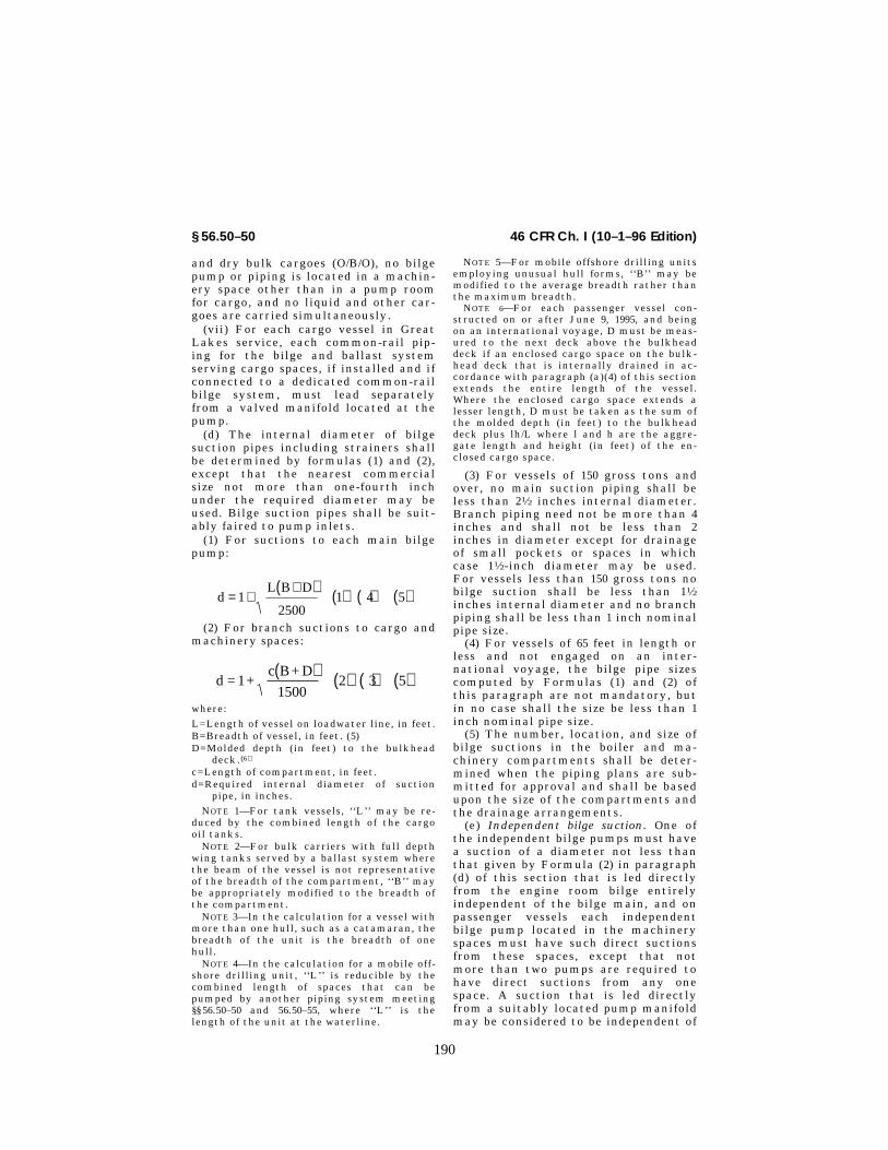
190
46 CFR Ch. I (10–1–96 Edition)§ 56.50–50
and dry bulk cargoes (O/B/O), no bilgepump or piping is located in a machin-ery space other than in a pump roomfor cargo, and no liquid and other car-goes are carried simultaneously.
(vii) For each cargo vessel in GreatLakes service, each common-rail pip-ing for the bilge and ballast systemserving cargo spaces, if installed and ifconnected to a dedicated common-railbilge system, must lead separatelyfrom a valved manifold located at thepump.
(d) The internal diameter of bilgesuction pipes including strainers shallbe determined by formulas (1) and (2),except that the nearest commercialsize not more than one-fourth inchunder the required diameter may beused. Bilge suction pipes shall be suit-ably faired to pump inlets.
(1) For suctions to each main bilgepump:
dL B D
= ++( ) ( ) ( ) ( )1
25001 4 5
(2) For branch suctions to cargo andmachinery spaces:
d = 1+c B+ D( ) ( ) ( ) ( )
15002 3 5
where:
L=Length of vessel on loadwater line, in feet.B=Breadth of vessel, in feet. (5)D=Molded depth (in feet) to the bulkhead
deck.(6)
c=Length of compartment, in feet.d=Required internal diameter of suction
pipe, in inches.
NOTE 1—For tank vessels, ‘‘L’’ may be re-duced by the combined length of the cargooil tanks.
NOTE 2—For bulk carriers with full depthwing tanks served by a ballast system wherethe beam of the vessel is not representativeof the breadth of the compartment, ‘‘B’’ maybe appropriately modified to the breadth ofthe compartment.
NOTE 3—In the calculation for a vessel withmore than one hull, such as a catamaran, thebreadth of the unit is the breadth of onehull.
NOTE 4—In the calculation for a mobile off-shore drilling unit, ‘‘L’’ is reducible by thecombined length of spaces that can bepumped by another piping system meeting§§ 56.50–50 and 56.50–55, where ‘‘L’’ is thelength of the unit at the waterline.
NOTE 5—For mobile offshore drilling unitsemploying unusual hull forms, ‘‘B’’ may bemodified to the average breadth rather thanthe maximum breadth.
NOTE 6—For each passenger vessel con-structed on or after June 9, 1995, and beingon an international voyage, D must be meas-ured to the next deck above the bulkheaddeck if an enclosed cargo space on the bulk-head deck that is internally drained in ac-cordance with paragraph (a)(4) of this sectionextends the entire length of the vessel.Where the enclosed cargo space extends alesser length, D must be taken as the sum ofthe molded depth (in feet) to the bulkheaddeck plus lh/L where l and h are the aggre-gate length and height (in feet) of the en-closed cargo space.
(3) For vessels of 150 gross tons andover, no main suction piping shall beless than 21⁄2 inches internal diameter.Branch piping need not be more than 4inches and shall not be less than 2inches in diameter except for drainageof small pockets or spaces in whichcase 11⁄2-inch diameter may be used.For vessels less than 150 gross tons nobilge suction shall be less than 11⁄2inches internal diameter and no branchpiping shall be less than 1 inch nominalpipe size.
(4) For vessels of 65 feet in length orless and not engaged on an inter-national voyage, the bilge pipe sizescomputed by Formulas (1) and (2) ofthis paragraph are not mandatory, butin no case shall the size be less than 1inch nominal pipe size.
(5) The number, location, and size ofbilge suctions in the boiler and ma-chinery compartments shall be deter-mined when the piping plans are sub-mitted for approval and shall be basedupon the size of the compartments andthe drainage arrangements.
(e) Independent bilge suction. One ofthe independent bilge pumps must havea suction of a diameter not less thanthat given by Formula (2) in paragraph(d) of this section that is led directlyfrom the engine room bilge entirelyindependent of the bilge main, and onpassenger vessels each independentbilge pump located in the machineryspaces must have such direct suctionsfrom these spaces, except that notmore than two pumps are required tohave direct suctions from any onespace. A suction that is led directlyfrom a suitably located pump manifoldmay be considered to be independent of

191
Coast Guard, DOT § 56.50–50
the bilge main. Where two direct suc-tions are required in any one compart-ment on passenger vessels, one suctionmust be located on each side of thecompartment. If watertight bulkheadsseparate the engine and boiler rooms, adirect suction or suctions must befitted to each compartment unless thepumps available for bilge service aredistributed throughout these compart-ments, in which case at least one pumpin each such compartment must befitted with direct suction in its com-partment. In a vessel with more thanone hull, there must be one bilge pumpthat has an independent bilge suctionin each hull. In a column stabilized mo-bile offshore drilling unit, the inde-pendent bilge suction must be from thepumproom bilge.
(f) Emergency bilge suctions. In addi-tion to the independent bilge suction(s)required by paragraph (e) of this sec-tion, an emergency bilge suction mustbe provided in the machinery space forall self-propelled vessels as described inthe following subparagraphs. Emer-gency suctions must be provided frompumps other than those required by§ 56.50–55(a) of this part. Such suctionsmust have nonreturn valves, and mustmeet the following criteria as appro-priate:
(1) On passenger vessels propelled bysteam and operating on an inter-national voyage or on ocean, coastwise,or Great Lakes routes, the main cir-culating pump is to be fitted with a di-rect bilge suction for the machineryspace. The diameter of such suctionsshall not be less than two-thirds the di-ameter of the main sea injection. Whenit can be shown to the satisfaction ofthe Commandant that the main cir-culating pump is not suitable for emer-gency bilge service, a direct emergencybilge suction is to be led from the larg-est available independent power drivenpump to the drainage level of the ma-chinery space. The suction is to be ofthe same diameter as the main inlet ofthe pump used and the capacity of thepump shall exceed that of a requiredmain bilge pump.
(2) On passenger vessels propelled byinternal combustion engines and oper-ating on an international voyage or onocean, coastwise, or Great Lakesroutes, the largest available pump in
the engine room is to be fitted with thedirect bilge suction in the machineryspace except that a required bilgepump may not be used. The area of thesuction pipe is to be equal to the fullsuction inlet of the pump. The dis-charge capacity of the pump selectedshall exceed the capacity of the re-quired main bilge pump.
(3) Vessels over 180 feet in lengthwhich are not passenger vessels andwhich operate on international voyagesor in ocean, coastwise, or Great Lakesservice, must be provided with a directemergency bilge suction from anypump in the machinery space, exceptthat a required bilge pump may not beused. The discharge capacity of thepump selected must exceed the capac-ity of the required main bilge pumpand the area of the suction inlet is tobe equal to the full suction inlet of thepump.
(4) Vessels under 180 feet in lengthneed not provide an emergency bilgesuction, except that passenger vesselsshall comply with the requirements ofparagraphs (f) (1) and (2) of this sec-tion.
(5) Each vessel with more than onehull must have an emergency bilge suc-tion in each hull.
(6) Each column stabilized mobile off-shore drilling unit must have—
(i) An emergency bilge suction ineach hull; and
(ii) A remote control for the emer-gency pump and associated valves thatcan be operated from the ballast con-trol room.
(g) Each individual bilge suctionshall be fitted with a suitable bilgestrainer having an open area of not lessthan three times at of the suction pipe.In addition a mud box or basket strain-er shall be fitted in an accessible posi-tion between the bilge suction mani-fold and the pump.
(h) Pipes for draining cargo holds ormachinery spaces must be separatefrom pipes which are used for filling oremptying tanks where water or oil iscarried. Bilge and ballast piping sys-tems must be so arranged as to preventoil or water from the sea or ballastspaces from passing into cargo holds ormachinery spaces, or from passingfrom one compartment to another,whether from the sea, water ballast, or
VerDate 27-NOV-96 08:03 Dec 23, 1996 Jkt 167174 PO 00000 Frm 00191 Fmt 8010 Sfmt 8010 E:\CFR\167174.040 167174

192
46 CFR Ch. I (10–1–96 Edition)§ 56.50–55
oil tanks, by the appropriate installa-tion of stop and non-return valves. Thebilge and ballast mains must be fittedwith separate control valves at thepumps. Except as allowed by paragraph(c)(4)(vii) of this section, piping fordraining a cargo hold or machineryspace must be separate from pipingused for filling or emptying any tankwhere water or oil is carried. Piping forbilge and ballast must be arranged soas to prevent, by the appropriate in-stallation of stop and non-returnvalves, oil or water from the sea or bal-last spaces from passing into a cargohold or machinery space, or from pass-ing from one compartment to another,regardless of the source. The bilge andballast mains must be fitted with sepa-rate control valves at the pumps.
(i) Ballast piping shall not be in-stalled to any hull compartment of awood vessel. Where the carriage of liq-uid ballast in such vessels is necessary,suitable ballast tanks, structurallyindependent of the hull, shall be pro-vided.
(j) When dry cargo is to be carried indeep tanks, arrangement shall be madefor disconnecting or blanking-off theoil and ballast lines, and the bilge suc-tions shall be disconnected or blanked-off when oil or ballast is carried. Blindflanges or reversible pipe fittings maybe employed for this purpose.
(k) Where bilge and ballast piping isled through tanks, except ballast pip-ing in ballast tanks, means must beprovided to minimize the risk of flood-ing of other spaces due to pipe failurewithin the tanks. In this regard, suchpiping may be in an oiltight or water-tight pipe tunnel, or the piping may beof Schedule 80 pipe wall thickness,fitted with expansion bends, and alljoints within the tanks are welded. Al-ternative designs may be installed asapproved by the Marine Safety Center.Where a pipe tunnel is installed, thewatertight integrity of the bulkheadsmust be maintained. No valve or fit-
ting may be located within the tunnelif the pipe tunnel is not of sufficientsize to afford easy access. These re-quirements need not be met providedthe contents of the tank and pipingsystem are chemically compatible andstrength and stability calculations aresubmitted showing that crossfloodingresulting from a pipe, the tank, and thespaces through which the piping passeswill not seriously affect the safety ofthe ship, including the launching oflifeboats due to the ship’s listing. Bilgelines led through tanks without a pipetunnel must be fitted with nonreturnvalves at the bilge suctions.
(l) When bilge pumps are utilized forother services, the piping shall be soarranged that under any condition atleast one pump will be available fordrainage of the vessel through an over-board discharge, while the otherpump(s) are being used for a differentservice.
(m) All bilge pipes used in or underfuel storage tanks or in the boiler ormachinery space, including spaces inwhich oil settling tanks or oil pumpingunits are located, shall be of steel orother acceptable material.
(n) Oil pollution prevention require-ments for bilge and ballast systems arecontained in subpart B of part 155,Title 33, Code of Federal Regulations.
NOTE: For the purposes of this section, apumproom is a machinery space on a columnstabilized mobile offshore drilling unit.
[CGFR 68–82, 33 FR 18843, Dec. 18, 1968, asamended by CGFR 69–127, 35 FR 9979, June 17,1970; CGD 73–58R, 39 FR 18767, May 30, 1974;79–165a, 45 FR 64188, Sept. 29, 1980; CGD 77–140, 54 FR 40608, Oct. 2, 1989; 55 FR 39968, Oct.1, 1990; CGD 83–043, 60 FR 24772, May 10, 1995]]
§ 56.50–55 Bilge pumps.
(a) Self-propelled vessels. (1) Each self-propelled vessel must be provided witha power-driven pump or pumps con-nected to the bilge main as required byTable 56.50–55(a).
VerDate 27-NOV-96 08:03 Dec 23, 1996 Jkt 167174 PO 00000 Frm 00192 Fmt 8010 Sfmt 8010 E:\CFR\167174.040 167174

193
Coast Guard, DOT § 56.50–55
TABLE 56.50–55(a).—POWER BILGE PUMPS REQUIRED FOR SELF-PROPELLED VESSELS
Vessel length, in feet
Passenger vessels 1 Dry-cargo vessels 2 Tankvessels
MobileoffshoredrillingunitsInter-
nationalvoyages 3
Ocean,coast-
wise andGreatLakes
All otherwaters
Ocean,coast-
wise andGreatLakes
All waters All watersAll waters
180′ or more .............................................. 4 3 4 3 2 2 2 2 2Below 180′ and exceeding 65′ .................. 4 3 5 2 5 2 5 2 5 2 2 265′ or less .................................................. 3 1 1 1 1 1 ................
1 Small passenger vessels under 100 gross tons refer to Subpart 182.25 of Subchapter T (Small Passenger Vessel) of thischapter.
2 Dry-bulk carriers having ballast pumps connected to the tanks outside the engineroom and to the cargo hold may substitutethe appropriate requirements for tank vessels.
3 Not applicable to passenger vessels which do not proceed more than 20 mile from the nearest land, or which are employedin the carriage of large numbers of unberthed passengers in special trades.
4 When the criterion numeral exceeds 30, an additional independent power-driven pump is required. (See Part 171 of thischapter for determination of criterion numeral.)
5 Vessels operating on lakes (including Great Lakes), bays, sounds, or rivers where steam is always available, or where a suit-able water supply is available from a power-driven pump of adequate pressure and capacity, may substitute siphons or eductorsfor one of the required power-driven pumps, provided a siphon or eductor is permanently installed in each hold or compartment.
(b) Nonself-propelled vessels. (1) Oceangoing sailing vessels and barges shallbe provided with pumps connected to
the bilge main as required in Table56.50–55(b)(1).
TABLE 56.50–55(b)(1)—Bilge Pumps Required for Nonself-Propelled Vessels
Type of vessel Waters navigated Power pumps (1) Handpumps
Sailing .................................................. Ocean and coastwise ....................... Two ................................................... (2)
Manned barges ................................... ......do ................................................ Two ................................................... (2)
Manned barges ................................... Other than ocean and coastwise ...... (3) ....................................................... (3)
Unmanned barges ............................... All waters .......................................... (3) ....................................................... (3)
Mobile offshore drilling units ............... All waters .......................................... Two .................................................... None.
1 Where power is always available, independent power bilge pumps shall be installed as required and shall be connected tothe bilge main.
2 Efficient hand pumps connected to the bilge main may be substituted for the power pumps. Where there is no common bilgemain, one hand pump will be required for each compartment.
3 Suitable hand or power pumps or siphons, portable or fixed, carried either on board the barge or on the towing vessel shallbe provided.
(2) The pumps and source of power foroperation on oceangoing sailing vesselsand barges shall be located above thebulkhead deck or at the highest con-venient level which is always acces-sible.
(3) Each hull of a vessel with morethan one hull, such as a catamaran,must meet Table 56.50–55(b).
(c) Capacity of independent power bilgepump. Each power bilge pump musthave the capacity to develop a suctionvelocity of not less than 400 feet perminute through the size of bilge mainpiping required by § 56.50–50(d)(1) of thispart under ordinary conditions; exceptthat, for vessels of less than 65 feet inlength not engaged on internationalvoyages, the pump must have a mini-mum capacity of 25 gallons per minute
and need not meet the velocity require-ment of this paragraph.
(d) Priming. Suitable means shall beprovided for priming centrifugal pumpswhich are not of the self-priming type.
(e) Location. (1) For self-propelledvessels, if the engines and boilers are intwo or more watertight compartments,the bilge pumps must be distributedthroughout these compartments. Onother self-propelled vessels and mobileoffshore drilling units, the bilge pumpsmust be in separate compartments tothe extent practicable. When the loca-tion of bilge pumps in separate water-tight compartments is not practicable,alternative arrangements may be sub-mitted for consideration by the MarineSafety Center.
(2) For nonself-propelled vessels re-quiring two bilge pumps, these pumps,
VerDate 27-NOV-96 08:03 Dec 23, 1996 Jkt 167174 PO 00000 Frm 00193 Fmt 8010 Sfmt 8010 E:\CFR\167174.040 167174
194
46 CFR Ch. I (10–1–96 Edition)§ 56.50–57
insofar as practicable, shall be locatedin separate watertight machineryspaces. When the location of bilgepumps in separate watertight compart-ments is not possible, the Commandantwill consider alternate arrangements ofthe bilge pumps.
(3) The emergency bilge pumps shallnot be installed in a passenger ship for-ward of the collision bulkhead.
(4) Each hull of a vessel with morethan one hull must have at least twomeans for pumping the bilges in eachhull. No multi-hulled vessel may oper-ate unless one of these means is avail-able to pump each bilge.
(f) Other pumps. Sanitary, ballast,and general service pumps having therequired capacity may be accepted asindependent power bilge pumps if fittedwith the necessary connections to thebilge pumping system.
[CGFR 68–82, 33 FR 18843, Dec. 18, 1968, asamended by CGD 79–023, 48 FR 51007, Nov. 4,1983; CGD 77–140, 54 FR 40608, Oct. 2, 1989; 55FR 39968, Oct. 1, 1990; CGD 83–043, 60 FR 24773,May 10, 1995]
§ 56.50–57 Bilge piping and pumps, al-ternative requirements.
(a) If a passenger vessel complieswith §§ 171.075 and 171.082 of this chap-ter, its bilge pumping and piping sys-tems must meet §§ 56.50–50 and 56.50–55,except as follows:
(1) Each bilge pumping system mustcomply with—
(i) Regulation 19(b) of the Annex toIMCO Resolution A.265 (VIII) in placeof §§ 56.50–55(a)(1), 56.50–55(a)(3), and56.50–55(f);
(ii) Regulation 19(d) of the Annex toIMCO Resolution A.265 (VIII) in placeof § 56.50–55(a)(2).
(2) Each bilge main must complywith Regulation 19(i) of the Annex toIMCO Resolution A.265 (VIII) in placeof § 56.50–50(d) except—
(i) The nearest commercial pipe sizemay be used if it is not more than one-fourth inch under the required diame-ter; and
(ii) Each branch pipe must complywith § 56.50–50(d)(2).
(b) The standards referred to in thissection, which are contained in theInter-governmental Maritime Consult-ative Organization (IMCO) ResolutionA.265 (VIII), dated December 10, 1973,
are incorporated by reference. Thisdocument is available from the Na-tional Technical Information Service,Springfield, Virginia, 22151, under thetitle ‘‘Regulations on Subdivision andStability of Passenger Ships as Equiva-lent to part B of chapter II of the Inter-national Convention for the Safety ofLife at Sea, 1960’’ (Volume IV of theU.S. Coast Guard’s ‘‘Commandant’sInternational Technical Series’’, USCGCITS–74–1–1.)
[CGD 76–053, 47 FR 37553, Aug. 26, 1982, asamended by CGD 79–023, 48 FR 51007, Nov. 4,1983]
§ 56.50–60 Systems containing oil.(a)(1) Oil-piping systems for the
transfer or discharge of cargo or fueloil must be separate from other pipingsystems as far as practicable, and posi-tive means shall be provided to preventinterconnection in service.
(2) Fuel oil and cargo oil systemsmay be combined if the cargo oil sys-tems contain only Grade E oils andhave no connection to cargo systemscontaining grades of oil with lowerflash points or hazardous substances.
(3) Pumps used to transfer oil musthave no discharge connections to firemains, boiler feed systems, or condens-ers unless approved positive means areprovided to prevent oil from being acci-dentally discharged into any of theaforementioned systems.
(b) When oil needs to be heated tolower its viscosity, heating coils mustbe properly installed in each tank.
(1) Each drain from a heating coil aswell as each drain from an oil heatermust run to an open inspection tank orother suitable oil detector before re-turning to the feed system.
(2) As far as practicable, no part ofthe fuel-oil system containing heatedoil under pressure exceeding 180 KPa(26 psi) may be placed in a concealedposition so that defects and leakagecannot be readily observed. Each ma-chinery space containing a part of thesystem must be adequately illumi-nated.
(c) Filling pipes may be led directlyfrom the deck into the tanks or to amanifold in an accessible location per-manently marked to indicate the tanksto which they are connected. A shutoffvalve must be fitted at each filling end.
VerDate 27-NOV-96 08:03 Dec 23, 1996 Jkt 167174 PO 00000 Frm 00194 Fmt 8010 Sfmt 8010 E:\CFR\167174.040 167174

195
Coast Guard, DOT § 56.50–60
Oil piping must not be led through ac-commodation spaces, except that lowpressure fill piping not normally usedat sea may pass through accommoda-tion spaces if it is of steel construc-tion, all welded, and not concealed.
(d) Piping subject to internal headpressure from oil in the tank must befitted with positive shutoff valves lo-cated at the tank.
(1) Valves installed on the outside ofthe oil tanks must be made of steel,ductile cast iron ASTM A395, or a duc-tile nonferrous alloy having a meltingpoint above 1,700 °F and must be ar-ranged with a means of manual controllocally at the valve and remotely froma readily accessible and safe locationoutside of the compartment in whichthe valves are located.
(i) In the special case of a deep tankin any shaft tunnel, piping tunnel, orsimilar space, one or more valves mustbe fitted on the tank, but control inthe event of fire may be effected bymeans of an additional valve on thepiping outside the tunnel or similarspace. Any such additional valve in-stalled inside a machinery space mustbe capable of being operated from out-side this space.
(ii) [Reserved](2) If valves are installed on the in-
side of the tank, they may be made ofcast iron and arranged for remote con-trol only. Additional valves for localcontrol must be located in the spacewhere the system exits from the tankor adjacent tanks. Valves for local con-trol outside the tanks must be made ofsteel, ductile cast iron ASTM A395, ora ductile nonferrous alloy having amelting point above 1,700 °F.
(3) Power operated valves installed tocomply with the requirements of thissection must meet the following re-quirements:
(i) Valve actuators must be capableof closing the valves under all condi-tions, except during physical interrup-tion of the power system (e.g., cablebreakage or tube rupture). Fluid poweractuated valves, other than thoseopened against spring pressure, mustbe provided with an energy storage sys-tem which is protected, as far as prac-ticable, from fire and collision. Thestorage system must be used for noother purpose and must have sufficient
capacity to cycle all connected valvesfrom the initial valve position to theopposite position and return. The crossconnection of this system to an alter-nate power supply will be given specialconsideration by the Marine SafetyCenter.
(ii) The valve shall have a localpower actuator to both open and closethe valve unless local manual openingoperation will not prevent remote clos-ing of the valve.
(iii) The positioning of the valve byeither the local or remote actuatorsshall not void the ability of the otheractuator to close the valve.
(iv) The valve shall be provided witha means of emergency manual oper-ation to both open and close the valveregardless of the status of the poweroperating system. Such manual oper-ation may interfere with the power op-eration, and if so, shall be protectedfrom causal use by means of covers,locking devices, or other suitablemeans. Instructions and warnings re-garding the emergency system shall beconspicuously posted at the valve.
(4) Remote operation for shutoffvalves on small independent oil tankswill be specially considered in eachcase where the size of tanks and theirlocation may warrant the omission ofremote operating rods.
(e) Fuel oil tanks overhanging boilersare prohibited.
(f) Valves for drawing fuel or drain-ing water from fuel are not permittedin fuel oil systems except that a singlevalve may be permitted in the case ofdiesel driven machinery if suitably lo-cated within the machinery space awayfrom any potential source of ignition.Such a valve shall be fitted with a capor a plug to prevent leakage.
(g) Test cocks must not be fitted tofuel oil or cargo oil tanks.
(h) Oil piping must not run throughfeed or potable water tanks. Feed orpotable water piping must not passthrough oil tanks.
(i) Where flooding equalizing cross-connections between fuel or cargotanks are required for stability consid-erations, the arrangement must be ap-proved by the Marine Safety Center.
(j) Piping conveying oil must be runwell away from hot surfaces wherever
VerDate 27-NOV-96 08:03 Dec 23, 1996 Jkt 167174 PO 00000 Frm 00195 Fmt 8010 Sfmt 8010 E:\CFR\167174.040 167174
196
46 CFR Ch. I (10–1–96 Edition)§ 56.50–65
possible. Where such leads are unavoid-able, only welded joints are to be used,or alternatively, suitable shields are tobe fitted in the way of flanged or me-chanical pipe joints when welded jointsare not practicable. Piping that con-veys fuel oil or lubricating oil to equip-ment and is in the proximity of equip-ment or lines having an open flame orhaving parts operating above 500 °Fmust be of seamless steel. (See § 56.50–65 of this part.)
(k) Oil piping drains, strainers andother equipment subject to normal oilleakage must be fitted with drip pansor other means to prevent oil draininginto the bilge.
(l) Where oil piping passes through anon-oil tank without stop valves com-plying with paragraph (d) of this sec-tion installed at all tank penetrations,the piping must comply with § 56.50–50(k).
(m) Each arrangement for the stor-age, distribution, and use of oil in apressure-lubrication system must—
(1) As well as comply with § 56.50–80,be such as to ensure the safety of thevessel and all persons aboard; and
(2) In a machinery space, meet theapplicable requirements of §§ 56.50–60(b)(2) and (d), 56.50–85(a)(11), 56.50–90 (c)and (d), and 58.01–55(f) of this sub-chapter. No arrangement need complywith § 58.50–90 (c)(1) and (c)(3) of thissubchapter if the sounding pipe isfitted with an effective means of clo-sure, such as a threaded cap or plug orother means acceptable to the Officerin Charge, Marine Inspection. The useof flexible piping or hose is permittedin accordance with the applicable re-quirements of §§ 56.35–10, 56.35–15, and56.60–25(c).
(n) Each arrangement for the stor-age, distribution, and use of any otherflammable oil employed under pressurein a power transmission-system, con-trol and activating system, or heatingsystem must be such as to ensure thesafety of the vessel and all personsaboard by—
(1) Complying with Subpart 58.30 ofthis subchapter; and,
(2) Where means of ignition arepresent, meeting the applicable re-quirements of §§ 56.50–85(a)(11), 56.50–90(c) and (d), and 58.01–55(f) of this sub-chapter. Each pipe and its valves and
fittings must be of steel or other ap-proved material, except that the use offlexible piping or hose is permitted inaccordance with the applicable require-ments of §§ 56.35–10, 56.35–15, and 56.60–25(c).
[CGFR 68–82, 33 FR 18843, Dec. 18, 1968, asamended by CGFR 69–127, 35 FR 9979, June 17,1970; CGD 73–254, 40 FR 40165, Sept. 2, 1975;CGD 77–140, 54 FR 40609, Oct. 2, 1989; 55 FR39968, Oct. 1, 1990; CGD 83–043, 60 FR 24774,May 10, 1995]
§ 56.50–65 Burner fuel-oil service sys-tems.
(a) All discharge piping from the fueloil service pumps to burners must beseamless steel with a thickness of atleast Schedule 80. If required by § 56.07–10(e) of this part or paragraph 104.1.2 ofANSI B31.1, the thickness must begreater than Schedule 80. Short lengthsof steel, or annealed copper nickel,nickel copper, or copper pipe and tub-ing may be used between the fuel oilburner front header manifold and theatomizer head to provide flexibility.All material used must meet the re-quirements of subpart 56.60 of this part.The use of non-metallic materials isprohibited. The thickness of the shortlengths must not be less than the larg-er of 0.9 mm (0.35 inch) or that requiredby § 56.07–10(e) of this part. Flexible me-tallic tubing for this application maybe used when approved by the MarineSafety Center. Tubing fittings must beof the flared type except that flarelessfittings of the nonbite type may beused when the tubing is steel, nickelcopper or copper nickel.
(b)(1) All vessels having oil fired boil-ers must have at least two fuel servicepumps, each of sufficient capacity tosupply all the boilers at full power, andarranged so that one may be over-hauled while the other is in service. Atleast two fuel oil heaters of approxi-mately equal capacity must be in-stalled and so arranged that any heatermay be overhauled while the other(s) is(are) in service. Suction and dischargestrainers must be of the duplex orother type capable of being cleanedwithout interrupting the oil supply.
(2) All auxiliary boilers, except thosefurnishing steam for vital equipmentand fire extinguishing purposes otherthan duplicate installations, may be
VerDate 27-NOV-96 08:03 Dec 23, 1996 Jkt 167174 PO 00000 Frm 00196 Fmt 8010 Sfmt 8010 E:\CFR\167174.040 167174

197
Coast Guard, DOT § 56.50–70
equipped with a single fuel oil servicepump and a single fuel oil heater. Suchpumps need not be fitted with dis-charge strainers.
(3) Strainers must be located so as topreclude the possibility of spraying oilon the burner or boiler casing, or beprovided with spray shields. Coamings,drip pans, etc., must be fitted underfuel oil service pumps, heaters, etc.,where necessary to prevent oil drain-age to the bilge.
(4) Boilers burning fuel oils of lowviscosity need not be equipped withfuel oil heaters, provided acceptableevidence is furnished to indicate thatsatisfactory combustion will be ob-tained without the use of heaters.
(c) Piping between service pumps andburners shall be located so as to bereadily observable, and all boltedflange joints shall be provided with awrap around deflector to deflect sprayin case of a leak. The relief valve lo-cated at the pump and the relief valvesfitted to the fuel oil heaters shall dis-charge back into the settling tank orthe suction side of the pump. The re-turn line from the burners shall be soarranged that the suction piping can-not be subjected to discharge pressure.
(d) If threaded-bonnet valves are em-ployed, they shall be of the union-bon-net type capable of being packed underpressure.
(e) Unions shall not be used for pipediameters of 1 inch and above.
(f) Boiler header valves of the quickclosing type shall be installed in thefuel supply lines as close to the boilerfront header as practicable. The loca-tion is to be accessible to the operatoror remotely controlled.
(g) Bushings and street ells are notpermitted in fuel oil discharge piping.
(h) Each fuel-oil service pump mustbe equipped with controls as requiredby § 58.01–25 of this subchapter.
[CGFR 68–82, 33 FR 18843, Dec. 18, 1968, asamended by CGFR 69–127, 35 FR 9978, June 17,1970; CGD 77–140, 54 FR 40609, Oct. 2, 1989;CGD 83–043, 60 FR 24774, May 10, 1995]
§ 56.50–70 Gasoline fuel systems.
(a) Material. (1) Fuel supply piping tothe engines shall be of seamless drawnannealed copper pipe or tubing, nickelcopper, or copper nickel pipe or tubing
meeting the requirements of subpart56.60.
(2) Tubing wall thicknesses shall notbe less than the larger of that shown inTable 56.50–70(a), or as required by§ 56.07–10(e) and 104.1.2 of ANSI–B31.1.
(3) Tubing fittings shall be of non-ferrous drawn or forged metal and ofthe flared type except that the flarelessfittings of the nonbite type may beused when the tubing system is of nick-el copper or copper nickel. Tubing shallbe cut square and flared by suitabletools. Tube ends shall be annealed be-fore flaring. Pipe fittings shall be ofnonferrous material. Pipe thread jointsshall be made tight with a suitablecompound.
(4) Valves for fuel lines shall be ofnonferrous material of the union bon-net type with ground seats except thatcocks may be used if they are the solidbottom type with tapered plugs andunion bonnets.
TABLE 56.50–70(a)—TUBING WALL THICKNESS
Outside diameter of tubing in inchesThickness
B.W.G. Inch
1⁄8, 3⁄16, 1⁄4 .......................................... #21 0.0325⁄16, 3⁄8 ................................................ #20 .0357⁄16, 1⁄2 ................................................ #19 .042
(b) Installation. (1) All fuel pipes, pipeconnections, and accessories shall bereadily accessible. The piping shall runin sight wherever practicable, pro-tected against mechanical injury, andeffectively secured against excessivemovement and vibration by the use ofsoft nonferrous metal liners or strapswithout sharp edges. Where passingthrough steel decks or bulkheads, fuellines shall be protected by close fittingferrules or stuffing boxes. Refer to§ 56.30–25 for tubing joint installations.
(2) A short length of suitable metallicor nonmetallic flexible tubing or hose,or a loop of annealed copper tubingshall be installed in the fuel supply lineat or near the engine to prevent dam-age by vibration. If nonmetallic flexi-ble hose is used it shall meet the re-quirements of § 56.60–25(c) for fuel serv-ice. Flexible hose connections shouldmaintain metallic contact between thesections of the fuel supply lines; how-ever, if such contact is not maintained,the fuel tank shall be grounded.
VerDate 27-NOV-96 08:03 Dec 23, 1996 Jkt 167174 PO 00000 Frm 00197 Fmt 8010 Sfmt 8010 E:\CFR\167174.040 167174

198
46 CFR Ch. I (10–1–96 Edition)§ 56.50–75
(3) Valves in fuel lines shall be in-stalled to close against the flow.
(c) Shutoff valves. Shutoff valves of asuitable type shall be installed in thefuel supply lines, one as close to eachtank as practicable, and one as close toeach carburetor as practicable. Wherefuel tanks are installed below theweather deck, arrangements shall beprovided for operating all shutoffvalves at the tanks from outside thecompartments in which they are lo-cated, preferably from an accessible po-sition on the weather deck. The operat-ing gear for the shutoff valves at thetanks shall be accessible at all timesand shall be suitably marked.
(d) Strainers. A suitable twin strainershall be fitted in the fuel supply line inthe engine compartment. Strainersshall be of the type opening on top forcleaning screens. A drip pan shall befitted under the strainer.
(e) Outlets and drains. Outlets in fuellines for drawing gasoline for any pur-pose are prohibited. Valved openings inthe bottom of fuel tanks are prohib-ited; however, openings fitted withthreaded plug or cap can be used forcleaning purposes.
(f) Fuel suction connections. All fuelsuction and return lines shall enter thetop of the fuel tanks and connectionsshall be fitted into spuds. Such linesshall extend nearly to the bottom ofthe tank.
(g) Filling and sounding pipes. Fillingand sounding pipes shall be so arrangedthat vapors or possible overflow whenfilling cannot escape to the inside ofthe vessel but will discharge overboard.Such pipes shall terminate on theweather deck clear of any coamingsand shall be fitted with suitable shutoffvalves or deck plugs. Filling and sound-ing pipes shall extend to within one-half of their diameter from the bottomof the tank or from the surface of thestriking plate in case of a soundingpipe. A flame screen of noncorrodiblewire mesh shall be fitted in the throatof the filling pipe. Sounding pipes shallbe kept closed at all times except dur-ing sounding.
(h) Vent pipes. Each tank shall befitted with a vent, the cross-sectionalarea of which shall not be less thanthat of the filling pipe. The vent pipesshall terminate at least 2 feet above
the weather deck and not less than 3feet from any opening into living quar-ters or other below deck space. Theends of vent pipes shall terminate withU-bends and shall be fitted with flamescreens or flame arresters. The flamescreens shall consist of a single screenof corrosion resistant wire of at least30 by 30 mesh.
(i) Gasoline tanks. For requirementspertaining to independent gasoline fueltanks see subpart 58.50 of this sub-chapter.
(j) Fuel pumps. Each fuel pump mustbe equipped with controls as requiredby § 58.01–25 of this subchapter.
[CGFR 68–82, 33 FR 18843, Dec. 18, 1968, asamended by CGFR 69–127, 35 FR 9978, June 17,1970; CGFR 72–59R, 37 FR 6189, Mar. 25, 1972;CGD 83–043, 60 FR 24774, May 10, 1995]
§ 56.50–75 Diesel fuel systems.(a) Vessels greater than 100 gross tons.
(1) The diesel fuel system shall complywith §§ 56.50–60, 56.50–85, and 56.50–90.The fuel supply piping to engines shallbe of seamless steel, annealed seamlesscopper or brass pipe or tubing, or ofnickel copper or copper nickel alloymeeting the requirements of subpart56.60 for materials and § 56.50–70(a)(2)for thickness. Fuel oil service or unitpumps shall be equipped with controlsto comply with § 58.01–25 of this sub-chapter.
(2) The installation shall complywith § 56.50–70(b).
(3) Tubing connections and fittingsshall be drawn or forged metal of theflared type except that flareless fit-tings of the nonbite type may be usedwhen the tubing system is steel, nick-el-copper, or copper-nickel. When mak-ing flared tube connections the tubingshall be cut square and flared by suit-able tools. Tube ends shall be annealedbefore flaring.
(b) Vessels of 100 gross tons and lessand tank barges. (1) Materials. Fuel sup-ply piping shall be of copper, nickelcopper or copper nickel having a mini-mum wall thickness of 0.035 inch ex-cept that piping of other materialssuch as seamless steel pipe or tubingwhich provides equivalent safety maybe used.
(2) Tubing connections and fittings.Tubing connections shall comply withthe provisions of § 56.50–75(a)(3).
VerDate 27-NOV-96 08:03 Dec 23, 1996 Jkt 167174 PO 00000 Frm 00198 Fmt 8010 Sfmt 8010 E:\CFR\167174.040 167174
199
Coast Guard, DOT § 56.50–80
(3) Installation. The installation ofdiesel fuel piping shall comply with therequirements of § 56.50–70(b).
(4) Shutoff valves. Shutoff valves shallbe installed in the fuel supply lines,one as close to each tank as prac-ticable, and one as close to each fuelpump as practicable. Valves shall beaccessible at all times.
(5) Outlets and drains. Valves for re-moving water or impurities from fueloil systems will be permitted in themachinery space provided such valvesare fitted with caps or plugs to preventleakage.
(6) Filling pipe. Tank filling pipes onmotorboats and motor vessels of lessthan 100 gross tons and tank bargesshall terminate on an open deck andshall be fitted with suitable shutoffvalves, deck plugs, or caps.
(7) Vent pipes. Each tank shall befitted with a vent pipe complying with§ 56.50–85.
(8) Independent diesel fuel tanks. Seesubpart 58.50 of this subchapter for spe-cific requirements.
[CGFR 68–82, 33 FR 18843, Dec. 18, 1968, asamended by CGD 77–140, 54 FR 40610, Oct. 2,1989]
§ 56.50–80 Lubricating-oil systems.(a) The lubricating oil system shall
be designed to function satisfactorilywhen the vessel has a permanent 15°list and a permanent 5° trim.
(b) When pressure or gravity-forcedlubrication is employed for the steamdriven main propelling machinery, anindependent auxiliary lubricatingpump shall be provided.
(c) Oil coolers on steam driven ma-chinery shall be provided with two sep-arate means of circulating waterthrough the coolers.
(d) For internal combustion engineinstallations, the requirements of para-graphs (b) and (c) of this section shallbe met, but they do not apply to ves-sels in river and harbor service, nor toany vessel below 300 gross tons. Wherethe size and design of an engine is suchthat lubrication before starting is notnecessary and an attached pump is nor-mally used, the independent auxiliarypump is not required if a duplicate ofthe attached pump is carried as spare.In meeting the requirements of para-graph (c) of this section in the case of
internal combustion engines, two sepa-rate means are to be provided for cir-culating coolant on those engines onwhich oil coolers are fitted. One ofthose means must be independentlydriven and may consist of a connectionfrom a pump of adequate size normallyused for other purposes utilizing the re-quired coolant. Where the design of anengine will not readily accommodatean independent pump connection, theindependent auxiliary pump will not berequired if a duplicate of the attachedpump is carried as a spare. Oil filtersshall be provided on all internal com-bustion engine installations. On mainpropulsion engines which are fittedwith full-flow type filters, the arrange-ment shall be such that the filters maybe cleaned without interrupting the oilsupply except that such an arrange-ment is not required on vessels havingmore than a single main propulsion en-gine.
(e) The lubricating oil piping shall beindependent of other piping systemsand shall be provided with necessarycoolers, heaters, filters, etc., for properoperation. Oil heaters shall be fittedwith bypasses.
(f) Diesel engine lubrication systemsshall be so arranged that vapors fromthe sump tank may not be dischargedback into the engine crank case of en-gines of the dry sump type.
(g) Steam turbine driven propulsionand auxiliary generating machinery de-pending on forced lubrication shall bearranged to shut down automaticallyupon failure of the lubricating system.
(h) Sight-flow glasses may be used inlubricating-oil systems provided it hasbeen demonstrated, to the satisfactionof the Commanding Officer, MarineSafety Center, that they can withstandexposure to a flame at a temperature of927°C (1700°F) for one hour, withoutfailure or appreciable leakage.
(i) Steam driven propulsion machin-ery must be provided with an emer-gency supply of lubricating oil thatmust operate automatically upon fail-ure of the lubricating oil system. Theemergency oil supply must be adequate
VerDate 27-NOV-96 08:03 Dec 23, 1996 Jkt 167174 PO 00000 Frm 00199 Fmt 8010 Sfmt 8010 E:\CFR\167174.040 167174

200
46 CFR Ch. I (10–1–96 Edition)§ 56.50–85
to provide lubrication until the equip-ment comes to rest during automaticshutdown.
[CGFR 68–82, 33 FR 18843, Dec. 18, 1968, asamended by CGFR 69–127, 35 FR 9979, June 17,1970; CGD 81–030, 53 FR 17837, May 18, 1988;CGD 83–043, 60 FR 24774, May 10, 1995]
§ 56.50–85 Tank-vent piping.(a) This section applies to vents for
all independent, fixed, non-pressuretanks or containers or for spaces inwhich liquids, such as fuel, ship’sstores, cargo, or ballast, are carried.
(1) The structural arrangement indouble bottom and other tanks shall besuch as to permit the free passage ofair and gases from all parts of thetanks to vent pipes.
(2) Tanks having a comparativelysmall surface, such as fuel oil settlingtanks, need be fitted with only onevent pipe, but tanks having a compara-tively large surface shall be fitted withat least two vent pipes. The vents shallbe located so as to provide venting ofthe tanks under any service condition.
(3) Vent pipes for fuel oil tanks shall,wherever possible, have a slope of noless than 30°. Header lines, where bothends are adequately drained to a tank,are excluded from this requirement.
(4) Tank vents must extend above theweather deck, except vents from freshwater tanks, bilge oily-water holdingtanks, bilge slop tanks, and tanks con-taining Grade E combustible liquids,such as lubricating oil, may terminatein the machinery space, provided—
(i) The vents are arranged to preventoverflow on machinery, electricalequipment, and hot surfaces;
(ii) Tanks containing combustibleliquids are not heated; and
(iii) The vents terminate above thedeep load waterline if the tanks haveboundaries in common with the hull.
(5) Vents from oil tanks must termi-nate not less than three feet from anyopening into living quarters.
(6) Vents extending above thefreeboard deck or superstructure deckfrom fuel oil and other tanks must beat least Schedule 40 in wall thickness.Except for barges in inland service andfor Great Lakes vessels, the heightfrom the deck to any point wherewater may gain access through thevent to below deck must be at least 30
inches (760mm) on the freeboard deckand 171⁄2 inches (450mm) on the super-structure deck. On Great Lakes ves-sels, the height from the deck to anypoint where water may gain accessthrough the vent to below deck mustbe at least 30 inches (760mm) on thefreeboard deck, 24 inches (610mm) onthe raised quarterdeck, and 12 inches(305mm) on other superstructure decks.Where the height of vents on GreatLakes vessels may interfere with theworking of the vessel, a lower heightmay be approved by the Marine SafetyCenter provided the vent cap is prop-erly protected from mechanical dam-age. For barges in inland service, thevents must extend at least six inchesabove the deck. A lesser amount maybe approved by the Marine Safety Cen-ter if evidence is provided that a par-ticular vent has proven satisfactory inservice.
(7) Satisfactory means, permanentlyattached, shall be provided for closingthe openings of all vents, except thatbarges in inland service may be ex-empted. Acceptable means of closureare:
(i) A ball check valve where the ballfloat, normally in the open position,will float up and close under the actionof a submerging wave. The valve shallbe designed so that the effective cleardischarge area through the valve withthe float in the open position is notless than the inlet area of the vent pipeto which the valve is connected.
(ii) A hinged closure normally openon the outlet of the return bend, whichmust close automatically by the forceof a submerging wave; or
(iii) Another suitable device accept-able to the Commanding Officer, Ma-rine Safety Center.
(8) Vent outlets from all tanks whichmay emit flammable or combustiblevapors, such as bilge slop tanks andcontaminated drain tanks, must befitted with a single screen of corrosion-resistant wire of at least 30 by 30 mesh,or two screens of at least 20 by 20 meshspaced not less than one-half inch(13mm) nor more than 11⁄2 inches(38mm) apart. The clear area throughthe mesh must not be less than the in-ternal unobstructed area of the re-quired pipe.
VerDate 27-NOV-96 08:03 Dec 23, 1996 Jkt 167174 PO 00000 Frm 00200 Fmt 8010 Sfmt 8010 E:\CFR\167174.040 167174

201
Coast Guard, DOT § 56.50–90
(9) Where vents are provided withflame screens, the closure device shallbe situated so as not to damage thesescreens.
(10) The diameter of each vent pipemust not be less than 11⁄2 inches nomi-nal pipe size for fresh water tanks, 2inches nominal pipe size for water bal-last tanks, and 21⁄2 inches nominal pipesize for fuel oil tanks, except thatsmall independent tanks need not havea vent more than 25% greater in cross-sectional area than the fill line.
(11)(i) If a tank may be filled by apressure head exceeding that for whichthe tank is designed, the aggregatecross-sectional area of the vents ineach tank must be not less than thecross-sectional area of the filling lineunless the tank is protected by over-flows, in which case the aggregatecross-sectional area of the overflowsmust be not less than the cross-sec-tional area of the filling line.
(ii) Provision must be made to guardagainst liquids rising in the ventingsystem to a height that would exceedthe design head of a cargo tank or fuel-oil tank. It may be made by high-levelalarms or overflow-control systems orother, equivalent means, together withgauging devices and procedures for fill-ing cargo tanks.
(12) Where deep tanks are intendedfor the occasional carriage of dry orliquid cargo, a ‘‘spectacle’’ or ring andblank flange may be fitted in the over-flow pipe so arranged as not to inter-fere with venting when the tanks con-tain oil.
(13) Vents from fresh water or waterballast tanks shall not be connected toa common header with vents from oilor oily ballast tanks.
(b) Tank vents must remain withinthe watertight subdivision boundariesin which the tanks they vent are lo-cated. Where the structural configura-tion of a vessel makes meeting this re-quirement impracticable, the MarineSafety Center may permit a tank ventto penetrate a watertight subdivisionbulkhead. All tank vents which pene-trate watertight subdivision bulkheads
must terminate above the weatherdeck.
[CGFR 68–82, 33 FR 18843, Dec. 18, 1968, asamended by CGD 77–140, 54 FR 40610, Oct. 2,1989; CGD 83–043, 60 FR 24774, May 10, 1995;CGD 95–012, 60 FR 48050, Sept. 18, 1995]
§ 56.50–90 Sounding devices.(a) Each tank must be provided with
a suitable means of determining liquidlevel. Except for a main cargo tank ona tank vessel, each integral hull tankand compartment, unless at all timesaccessible while the vessel is operating,must be fitted with a sounding pipe.
(b) Where sounding pipes terminatebelow the freeboard deck on cargo ves-sels, they shall be fitted with gatevalves. On passenger vessels, wheresounding pipes terminate below thebulkhead deck, they shall be fittedwith self-closing gate valves.
(c) Except as allowed by this para-graph, on each vessel constructed on orafter June 9, 1995, no sounding pipeused in a fuel-oil tank may terminatein any space where the risk of ignitionof spillage from the pipe might arise.None may terminate in a space for pas-sengers or crew. When practicable,none may terminate in a machineryspace. When the Commanding Officer,Marine Safety Center, determines itimpracticable to avoid terminating apipe in a machinery space, a soundingpipe may terminate in a machineryspace if all the following requirementsare met:
(1) In addition to the sounding pipe,the fuel-oil tank has an oil-level gaugecomplying with paragraph (d) of thissection.
(2) The pipe terminates in a place re-mote from ignition hazards unless pre-cautions are taken such as fitting aneffective screen (shield) to prevent thefuel oil, in case of spillage through theend of the pipe, from coming into con-tact with a source of ignition.
(3) The end of the pipe is fitted witha self-closing blanking device and asmall-diameter, self-closing controlcock located below the blanking devicefor the purpose of ascertaining beforethe blanking device is opened that nofuel oil is present. Provision must bemade to ensure that no spillage of fuel
VerDate 27-NOV-96 08:03 Dec 23, 1996 Jkt 167174 PO 00000 Frm 00201 Fmt 8010 Sfmt 8010 E:\CFR\167174.040 167174

202
46 CFR Ch. I (10–1–96 Edition)§ 56.50–95
oil through the control cock involvesan ignition hazard.
(d) On each vessel constructed on orafter June 9, 1995, other oil-levelgauges may be used instead of soundingpipes if all the following requirementsare met:
(1) In a passenger vessel, no suchgauge may require penetration belowthe top of the tank, and neither thefailure of a gauge nor an overfilling ofthe tank may permit release of fuelinto the space.
(2) In a cargo vessel, neither the fail-ure of such a gauge nor an overfillingof the tank may permit release of fuelinto the space. The use of cylindricalgauge-glasses is prohibited. The use ofoil-level gauges with flat glasses andself-closing valves between the gaugesand fuel tanks is acceptable.
(e) The upper ends of sounding pipesterminating at the weather deck shallbe closed by a screw cap or plug. GreatLakes dry cargo carriers may have thesounding pipes which service ballastwater tanks terminate at least 4 inchesabove the deck if closure is provided bya tight fitting hinged cover makingmetal-to-metal contact with the hingeon the forward side. Positive means tosecure these caps in the closed positionshall be provided. No perforations oropenings will be permitted throughoutthe length of a sounding pipe wherefitted to oil tanks. Provision shall bemade to prevent damage to the vessels’plating by the striking of the soundingrod.
(f) On mobile offshore drilling unitswhere installation of sounding pipesmay not be practicable for some tanks,alternate means of determining liquidlevel may be used if approved by theCommandant.
[CGFR 68–82, 33 FR 18843, Dec. 18, 1968, asamended by CGD 73–251, 43 FR 56800, Dec. 4,1978; CGD 83–043, 60 FR 24774, May 10, 1995]
§ 56.50–95 Overboard discharges andshell connections.
(a)(1) All inlets and discharges ledthrough the vessel’s side shall be fittedwith efficient and accessible means, lo-cated as close to the hull penetrationsas is practicable, for preventing the ac-cidental admission of water into thevessel either through such pipes or inthe event of fracture of such pipes.
(2) The number of scuppers, sanitarydischarges, tank overflows, and othersimilar openings in the vessel’s sideshall be reduced to a minimum, eitherby making each discharge serve for asmany as possible of the sanitary andother pipes, or in any other satisfac-tory manner.
(3) In general, when the bulkheaddeck is above the freeboard deck, therequirements of this section apply rel-ative to the bulkhead deck. For vesselsnot assigned load lines, such as certaininland vessels and barges, the weatherdeck shall be taken as the freeboarddeck.
(b)(1) Scuppers and discharge pipesoriginating at any level and pentratingthe shell either more than 171⁄2 inches(450mm) below the freeboard deck orless than 231⁄2 inches (600mm) above thesummer load waterline must be pro-vided with an automatic nonreturnvalve at the shell. This valve, unlessrequired by paragraph (b)(2) of this sec-tion, may be omitted if the piping isnot less than Schedule 80 in wall thick-ness for nominal pipe sizes through 8inches, Schedule 60 for nominal pipesizes above 8 inches and below 16inches, and Schedule 40 for nominalpipe sizes 16 inches and above.
(2) Discharges led through the shelloriginating either from spaces belowthe freeboard deck or from within en-closed superstructures and equivalentdeckhouses on the freeboard deck asdefined in § 42.13–15(i) of subchapter E(Load Lines) of this chapter, shall befitted with efficient and accessiblemeans for preventing water from pass-ing inboard. Normally each separatedischarge shall have one automaticnonreturn valve with a positive meansof closing it from a position above thefreeboard deck. Where, however, thevertical upward distance from the sum-mer load line to the inboard end of thedischarge pipe through which floodingcan take place exceed 0.01L, the dis-charge may have two automatic non-return valves without positive meansof closing, provided that the inboardvalve is always accessible for examina-tion under service conditions. Wherethat vertical distance exceeds 0.02L asingle automatic nonreturn valve with-out positive means of closing is accept-able. In an installation where the two
VerDate 27-NOV-96 08:03 Dec 23, 1996 Jkt 167174 PO 00000 Frm 00202 Fmt 8010 Sfmt 8010 E:\CFR\167174.040 167174

203
Coast Guard, DOT § 56.50–95
automatic nonreturn valves are used,the inboard valve must be above thetropical load line. The means for oper-ating the positive action valve shall bereadily accessible and provided with anindicator showing whether the valve isopen or closed. A suitable arrangementshall be made to insure the valve is notclosed by unauthorized persons, and anotice shall be posted in a conspicuousplace at the operating station to the ef-fect that the valve shall not be closedexcept as required in an emergency.
(3) Where scuppers and drains are in-stalled in superstructures or deck-houses not enclosed as defined in§ 42.13–15(j) of subchapter E (LoadLines) of this chapter, they shall be ledoverboard. Refer to paragraph (b)(1) ofthis section for any nonreturn valve re-quirement.
(4) Sanitary pump discharges leadingdirectly overboard or via a holdingtank must meet the standards pre-scribed by this paragraph. The locationof the sanitary system openings withinthe vessel determines whether the re-quirements of paragraph (b)(2) or (3) ofthis section are applicable.
(c) Overflow pipes which dischargethrough the vessel’s side must be lo-cated as far above the deepest load lineas practicable and fitted with valves asrequired by paragraph (b) of this sec-tion. Two automatic nonreturn valvesmust be used unless it is impracticableto locate the inboard valve in an acces-sible position, in which case a non-return valve with a positive means ofclosure from a position above thefreeboard deck will be acceptable.Overflows which extend at least 30inches above the freeboard deck beforedischarging overboard may be fittedwith a single automatic nonreturnvalve at the vessel’s side. Overflowpipes which serve as tank vents mustnot be fitted with positive means ofclosure without the specific approval ofthe Marine Safety Center. Overflowpipes may be vented to the weather.
(d)(1) Sea inlets and discharges, suchas used in closed systems required forthe operation of main and auxiliarymachinery, as in pump connections orscoop injection heat exchanger connec-tions, need not meet the requirementsof paragraphs (b) (1) and (2) of this sec-tion but instead shall be fitted with a
shutoff valve located as near the shellplating as practicable, and may be lo-cally controlled if the valve is locatedin a manned machinery space. Thesecontrols shall be readily accessibleabove the floor plates and shall be pro-vided with indication showing whetherthe valve is opened or closed. Mannedmachinery spaces include the main ma-chinery space and are either attendedby the crew or are automated in ac-cordance with part 62 of this sub-chapter to be comparable to an at-tended space.
(2) In unmanned machinery spaces,all machinery inlets and discharges asdescribed in paragraph (d)(1) of thissection shall be remotely operablefrom a position above the freeboarddeck unless otherwise approved andshall meet the access and marking re-quirements of paragraph (b)(2) of thissection.
(e)(1) Pipes terminating at the shellplating shall be fitted with bends or el-bows between the outboard openingsand the first rigid connection inboard.In no case shall such pipes be fitted ina direct line between the shell openingand the first inboard connection.
(2) Seachests and other hull fittingsshall be of substantial constructionand as short as possible. They shall belocated as to minimize the possibilityof being blocked or obstructed.
(3) The thickness of inlet and dis-charge connections outboard of theshutoff valves, and exclusive ofseachests, must be not less than that ofSchedule 80 for nominal pipe sizesthrough 8 inches, Schedule 60 for nomi-nal pipe sizes above 8 inches and below16 inches, and Schedule 40 for nominalpipe sizes 16 inches and above.
(f) Valves required by this sectionand piping system components out-board of such required valves on newvessel installations or replacements invessels of 150 gross tons and over shallbe of a steel, bronze, or ductile castiron specification listed in Table 56.60–1(a). Lead or other heat sensitive mate-rials having a melting point of 1,700° F.or less shall not be used in such serv-ice, or in any other application wherethe deterioration of the piping systemin the event of fire would give rise todanger of flooding. Brittle materialssuch as cast iron shall not be used in
VerDate 27-NOV-96 08:03 Dec 23, 1996 Jkt 167174 PO 00000 Frm 00203 Fmt 8010 Sfmt 8010 E:\CFR\167174.040 167174
204
46 CFR Ch. I (10–1–96 Edition)§ 56.50–96
such service. Where nonmetallic mate-rials are used in a piping system, andshell closures are required by this sec-tion, a positive closure metallic valveis required (see also § 56.60–25).
(g) The inboard openings of ash andrubbish-chute discharges shall be fittedwith efficient covers. If the inboardopening is located below the freeboarddeck, the cover shall be watertight,and in addition, an automatic non-return valve shall be fitted in the chutein any easily accessible position abovethe deepest load line. Means shall beprovided for securing both the coverand the valve when the chute is not inuse. When ash-ejectors or similar ex-pelling devices located in the boiler-room have the inboard openings belowthe deepest load line, they shall befitted with efficient means for prevent-ing the accidental admission of water.The thickness of pipe for ash ejectordischarge shall be not less than Sched-ule 80.
(h) Where deck drains, soil lines, andsanitary drains discharge through theshell in way of cargo tanks on tankvessels, the valves required by this sec-tion shall be located outside the cargotanks. These valves shall meet the ma-terial requirements of paragraph (f) ofthis section. The piping led throughsuch tanks shall be fitted with expan-sion bends where required, and shall beof steel pipe having a wall thickness ofnot less than five-eighths inch, exceptthat the use of suitable corrosion-re-sistant material of lesser thicknesswill be given special consideration bythe Commandant. All pipe joints with-in the tanks shall be welded. Soil linesand sanitary drains which pass throughcargo tanks shall be provided with non-return valves with positive means ofclosing or other suitable means for pre-venting the entrance of gases into liv-ing quarters.
(i) Except as provided for in § 58.20–20(c) of this chapter, sea valves mustnot be held open with locks. Where it isnecessary to hold a discharge or intakeclosed with a lock, either a lockingvalve may be located inboard of the seavalve, or the design must be such thatthere is sufficient freedom of motion tofully close the locked sea valve afteran event, such as fire damage to theseat, causes significant leakage
through the valve. Valves which mustbe opened in and emergency, such asbilge discharges or fire pump suctionsmust not be locked closed, whetherthey are sea valves or not.
[CGFR 68–82, 33 FR 18843; Dec. 18, 1968, asamended by CGFR 69–127, 35 FR 9979, June 17,1970; CGFR 72–59R, 37 FR 6189, Mar. 25, 1972;CGD 81–030, 53 FR 17837, May 18, 1988; CGD 77–140, 54 FR 40610, Oct. 2, 1989]
§ 56.50–96 Keel cooler installations.
(a) Keel cooler installations shallmeet the requirements of § 56.50–95(d)(1)and (2), and (e)(3), and (f) except thatshutoff or isolation valves will not berequired for the inlet and dischargeconnections if:
(1) The installation is forward of thecollision bulkhead; or,
(2) The installation is integral withthe ship’s hull such that the coolertubes are welded directly to the hull ofthe vessel with the hull forming part ofthe tube and satisfies all of the follow-ing:
(i) The cooler structure is fabricatedfrom material of the same thicknessand quality as the hull plating towhich it is attached except that in thecase of half round pipe lesser thicknessmay be used if specifically approved bythe Commandant. In any case thestructure, with the exception of thehull proper, need not exceed three-eighths inch in thickness.
(ii) The flexible connections and allopenings internal to the vessel, such asexpansion tank vents and fills, in theinstallation are above the deepest loadline and all piping components areSchedule 80 or thicker below the deep-est load line.
(iii) Full penetration welds are em-ployed in the fabrication of the struc-ture and its attachment to the hull.
(iv) The forward end of the structuremust be faired to the hull such that thehorizontal length of the fairing is noless than four times the height of thestructure, or be in a protected locationsuch as inside a bow thruster trunk.
[CGFR 68–82, 33 FR 18843, Dec. 18, 1968, asamended by CGFR 72–59R, 37 FR 6189, Mar.25, 1972; CGD 77–140, 54 FR 40611, Oct. 2, 1989]
VerDate 27-NOV-96 08:03 Dec 23, 1996 Jkt 167174 PO 00000 Frm 00204 Fmt 8010 Sfmt 8010 E:\CFR\167174.040 167174

205
Coast Guard, DOT § 56.50–105
§ 56.50–97 Instrument, control andsampling piping (modifies 122.3).
(a) Instrument, control and samplingpiping must comply with paragraph122.3 of ANSI–B31.1 except that:
(1) Soldered type fittings may not beused.
(2) The outside diameter of takeoffconnections may not be less than 0.840inches for service conditions up to 900psi or 800° F., and 1.050 inches for condi-tions that exceed either of these limits.
[CGFR 68–82, 33 FR 18843, Dec. 18, 1968, asamended by CGFR 69–127, 35 FR 9978, June 17,1970; CGD 73–254, 40 FR 40165, Sept. 2, 1975]
§ 56.50–105 Low-temperature piping.(a) Class I–L. Piping systems des-
ignated to operate at temperaturesbelow 0° F. and pressures above 150pounds per square inch gage shall be ofClass I–L. Exceptions to this rule maybe found in the individual requirementsfor specific commodities in subchaptersD, I, and O of this chapter. The follow-ing requirements for Class I–L pipingsystems shall be satisfied:
(1) Materials. All materials used inlow temperature piping systems shallbe selected from among those specifica-tions listed in Table 56.50–105 and shallsatisfy all of the requirements of thespecifications, except that:
(i) The minimum service temperatureas defined in § 54.25–10(a)(2) of this sub-chapter shall not be colder than thatshown in Table 56.50–105; and
(ii) The material shall be tested forlow temperature toughness using theCharpy V-notch specimen of ASTM E–23, ‘‘Notched Bar Impact Testing of Me-tallic Materials’’, Type A, Figure 4.The toughness testing requirements ofsubpart 54.05 of this subchapter shall besatisfied for each particular productform. Charpy V-notch tests shall beconducted at temperatures not warmerthan 10° F. below the minimum servicetemperature of the design, except thatfor service temperatures of —320° F.and below, the impact test may be con-ducted at the service temperature. Theminimum average energy shall not beless than that shown in Table 56.50–105.In the case of steels conforming to thespecifications of Table 54.25–20(a) ofthis subchapter the minimum lateralexpansion shall not be less than thatrequired in § 54.25–20 of this subchapter.
The minimum energy permitted for asingle specimen and the minimumsubsize energies shall be those obtainedby multiplying the average energyshown in Table 56.50–105 by the applica-ble fraction shown in Table 56.50–105(a).
TABLE 56.50–105(a)—CHARPY V-NOTCHENERGY MULTIPLYING FACTORS
Charpy V-notch specimen size 1
Factor forminimum
energy, av-erage of 3
specimens 1
Factor forminimum
energy sin-gle speci-
men 1
10×10 mm .................................. 1 2/310×7.5 mm ................................. 5/6 5/910×5.0 mm ................................. 2/3 4/910×2.5 mm ................................. 1/2 1/3
1 Straight line interpolation for intermediate values is per-mitted.
(iii) Steels equivalent to those listedin Table 56.50–105 of this part, but notproduced according to a particularASTM specification, may be used onlywith the prior consent of the MarineSafety Center. Steels differing inchemical composition, mechanicalproperties or heat treatments fromthose specified may be specially ap-proved by the Marine Safety Center.Similarly, aluminum alloys and othernonferrous materials not covered inTable 56.50–105 of this part may be spe-cifically approved by the Marine Safe-ty Center for service at any low tem-perature. There are restrictions on theuse of certain materials in this partand in subchapter O of this chapter.
(2) Piping weldments. Pipingweldments shall be fabricated to sat-isfy the requirements of § 57.03–1(b) ofthis subchapter in addition to subpart56.70. Toughness testing of productionweldments for low temperature pipingsystems and assemblies is not required.
(3) Postweld heat treatment. All pipingweldments shall be postweld heattreated for stress relief in accordancewith the procedures of subpart 56.85.The only exceptions to this require-ment are for materials which do not re-quire postweld heat treatment asshown in Table 56.85–10. Relief frompostweld heat treatment shall not bedependent upon pipe thickness or weldjoint type.
(4) Nonacceptable joints. Single weldedbutt joints with backing ring left inplace, socket welds, slip-on flanges,pipe joining sleeves, and threaded
VerDate 27-NOV-96 08:03 Dec 23, 1996 Jkt 167174 PO 00000 Frm 00205 Fmt 8010 Sfmt 8010 E:\CFR\167174.041 167174
206
46 CFR Ch. I (10–1–96 Edition)§ 56.50–105
joints shall not be used, except in smalldiameter instrument lines.
(5) Other requirements. All other re-quirements of this part for Class I pip-ing apply to Class I–L piping. Pressuretesting must comply with subpart 56.97of this part, and nondestructive testingof circumferentially welded jointsmust comply with § 56.95–10. Seamlesstubular products must be used exceptthat, when the service pressure doesnot exceed 1724 KPa (250 psi), the Com-manding Officer, Marine Safety Center,may give special consideration to ap-propriate grades of piping and tubingthat are welded without the addition offiller metal in the root pass. Each pro-duction procedure and quality-controlprogram for welded products must beacceptable to the Officer in Charge,Marine Inspection.
(b) Class II–L. Piping systems de-signed to operate at temperaturesbelow 0° F. and pressures not higherthan 150 pounds per square inch gageshall be of Class II–L. Exceptions tothis rule may be found in the individ-ual requirements for specific commod-ities in subchapter D (Tank Vessels)and I (Cargo and Miscellaneous Ves-sels) of this chapter. The following re-quirements for Class II–L piping sys-tems shall be satisfied:
(1) Materials must be the same asthose required by paragraph (a)(1) ofthis section except that pipe and tub-ing of appropriate grades welded with-out the addition of a filler metal maybe used. The Commandant may give
special consideration to tubular prod-ucts welded with the addition of fillermetal.
(2) Piping weldments shall be fab-ricated to satisfy the requirements of§ 57.03–1(b) of this subchapter in addi-tion to subpart 56.70. Toughness testingof production weldments for low tem-perature piping systems and assembliesis not required.
(3) All piping weldments shall bepostweld heat treated for stress reliefin accordance with the procedures ofsubpart 56.85. The only exceptions tothis requirement are for materialswhich do not require postweld heattreatment as shown in Table 56.85–10and for socket weld joints and slip-onflange weld attachments where theweld thickness does not exceed that ex-empted by this table. Otherwise, relieffrom post-weld heat treatment shallnot be dependent upon pipe thicknessor weld joint type.
(4) Socket welds in nominal sizesabove 3 inches, slip-on flanges in nomi-nal sizes above 4 inches, and threadedjoints in sizes above 1 inch shall not beused.
(5) Pressure testing must complywith Subpart 56.97, and nondestructivetesting of welded joints must complywith § 56.95–10.
(6) All other requirements containedin this part for Class II piping shall beapplicable to Class II–L systems, ex-cept that § 56.70–15(b)(3)(iv) shall notapply.
TABLE 56.50–105—ACCEPTABLE MATERIALS AND TOUGHNESS TEST CRITERIA 2
Product form ASTM specification 3 Grade 4 Minimum service tem-perature
Minimum avg Charpy Vnotch energy
Pipe .............................. 1 ................................... ¥30° F ........................ 20 ft. lb.3 ................................... ¥150° F ...................... 25 ft. lb.
Tube (carbon and low A–333 and 4 (A–333 only) ............. ¥100° F ...................... 25 ft. lb.alloy steels). A–334 .......................... 6 ................................... ¥30° F ........................ 20 ft. lb.
7 ................................... ¥100° F ...................... 25 ft. lb.8 ................................... ¥320° F ...................... Refer to § 54.25–20 of
this subchapter.Pipe (Austenitic stain-
less steel).A–312 .......................... All Grades .................... No limit ......................... Austenitic stainless
steel piping need beimpact tested onlywhen toughnesstests are specified insubpart 54.25 of thissubchapter for plat-ing of the same alloydesignation. Whensuch toughness testsare required, theminimum averageenergy is 25 ft. lb.
VerDate 27-NOV-96 08:03 Dec 23, 1996 Jkt 167174 PO 00000 Frm 00206 Fmt 8010 Sfmt 8010 E:\CFR\167174.041 167174
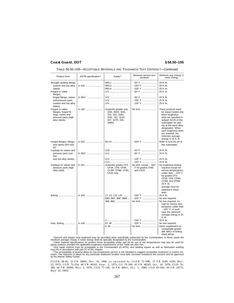
207
Coast Guard, DOT § 56.50–105
TABLE 56.50–105—ACCEPTABLE MATERIALS AND TOUGHNESS TEST CRITERIA 2—Continued
Product form ASTM specification 3 Grade 4 Minimum service tem-perature
Minimum avg Charpy Vnotch energy
Wrought welding fittings WPL1 ........................... ¥30° F ........................ 20 ft. lb.(carbon and low alloy A–420 .......................... WPL3 ........................... ¥150° F ...................... 25 ft. lb.steels). WPL4 ........................... ¥100° F ...................... 25 ft. lb.
Forged or rolledflanges,
LF1 ............................... ¥30° F ........................ 20 ft. lb.
forged fittings, valves A–350 1 ........................ LF2 ............................... ¥30° F ........................ 20 ft. lb.and pressure parts LF3 ............................... ¥150° F ...................... 25 ft. lb.(carbon and low alloy LF4 ............................... ¥100° F ...................... 25 ft. lb.steels).
Forged or rolledflanges, forged fit-tings, valves andpressure parts (highalloy steels).
A–182 .......................... Austenitic grades only(304, 304H, 304L,310, 316, 316H,316L, 321, 321H,347, 347H, 348,348H).
No limit ......................... These products needbe impact tested onlywhen toughnesstests are specified insubpart 54.25 of thissubchapter for plat-ing of the same alloydesignation. Whensuch toughness testsare required, theminimum averageenergy is 25 ft. lb.
Forged flanges, fittings, A–522 .......................... 9% Ni ........................... ¥320° F ...................... Refer to § 54.25–20 ofand valves (9% nick-el).
this subchapter.
Castings for valves and LCB .............................. ¥30° F ........................ 20 ft. lb.pressure parts (car-bon
A–3521 ......................... LC1 .............................. ¥50° F ........................ 20 ft. lb.
and low alloy steels). LC2 .............................. ¥100° F ...................... 25 ft. lb.LC3 .............................. ¥150° F ...................... 25 ft. lb.
Castings for valves andpressure parts (highalloy steel).
A–351 .......................... Austenitic grades CF3,CF3A, CF8, CF8A,CF3M, CF8M, CF8C,CK20 only.
No limit, except ¥325°F for grades CF8Cand CK20.
No toughness testingrequired except forservice temperaturescolder than ¥425° Ffor grades CF3,CF3A, CF8, CF8A,CF3M, and CF8M.25 ft. lb.average must beattained in thesetests.
Bolting .......................... A–320 .......................... L7, L9, L10, L43 .......... ¥150° F ...................... 20 ft. lb.B8D, B8T, B8F, B8M ... ¥325° F ...................... No test required.2B8, B8C ..................... No limit ......................... No test required, ex-
cept for service tem-peratures colder than¥425° F. In suchcase the minimumaverage energy is 25ft. lb.
4 ................................... ¥150° F ...................... 20 ft. lb.Nuts, bolting ................. A–194 .......................... 8T, 8F .......................... ¥325° F ...................... No test required.
8, 8C ............................ No limit ......................... Same requirement ascomparable grades(B8, B8C) of boltinglisted above.
1 Quench and temper heat treatment may be permitted when specifically authorized by the Commandant. In those cases theminimum average Charpy V-notch energy shall be specially designated by the Commandant.
2 Other material specifications for product forms acceptable under part 54 for use at low temperatures may also be used forpiping systems provided the applicable toughness requirements of this Table are also met.
3 Any repair method must be acceptable to the Commandant (G–MTH), and welding repairs as well as fabrication weldingmust be in accordance with part 57 of this chapter.
4 The acceptability of several alloys for low temperature service is not intended to suggest acceptable resistance to marine cor-rosion. The selection of alloys for any particular shipboard location must take corrosion resistance into account and be approvedby the Marine Safety Center.
[CGFR 68–82, 33 FR 18843, Dec. 18, 1968, as amended by CGFR 72–59R, 37 FR 6189, 6190, Mar.25, 1972; CGD 73–254, 40 FR 40165, Sept. 2, 1975; CG 79–108, 43 FR 46545, Oct. 10, 1978; CGD 74–289, 44 FR 26008, May 3, 1979; CGD 77–140, 54 FR 40611, Oct. 2, 1989; CGD 83–043, 60 FR 24775,May 10, 1995]
VerDate 27-NOV-96 08:03 Dec 23, 1996 Jkt 167174 PO 00000 Frm 00207 Fmt 8010 Sfmt 8006 E:\CFR\167174.041 167174

208
46 CFR Ch. I (10–1–96 Edition)§ 56.50–110
§ 56.50–110 Diving support systems.(a) In addition to the requirements of
this part, piping for diving installa-tions which is permanently installedon the vessel must meet the require-ments of subpart B (Commercial Div-ing Operations) of part 197 of this chap-ter.
(b) Piping for diving installationswhich is not permanently installed onthe vessel need not meet the require-ments of this part, but must meet therequirements of subpart B of part 197 ofthis chapter.
(c) Piping internal to a pressure ves-sel for human occupancy (PVHO) neednot meet the requirements of this part,but must meet the requirements ofsubpart B of part 197 of this chapter.
[CGD 76–009, 43 FR 53683, Nov. 16, 1978]
Subpart 56.60—Materials§ 56.60–1 Acceptable materials and
specifications (replaces 123 andTable 126.1 in ANSI–B31.1).
(a)(1) The material requirements inthis subpart shall be followed in lieu ofthose in 123 in ANSI–B31.1.
(2) Materials used in piping systemsmust be selected from the specifica-tions which appear in Table 56.60–1(a)
of this section or Table 56.60–2(a) ofthis part, or they may be selected fromthe material specifications of section I,III, or VIII of the ASME Code if notprohibited by a regulation of this sub-chapter dealing with the particularsection of the ASME Code. Table 56.60–1(a) of this section contains only pipe,tubing, and fitting specifications. De-termination of acceptability of plate,forgings, bolting, nuts, and castingsmay be made by reference to the ASMECode as previously described. Addition-ally, accepted materials for use as pip-ing system components appear in Table56.60–2(a) of this part. Materials con-forming to specifications not describedin this subparagraph must receive thespecific approval of the Marine SafetyCenter before being used. Materialslisted in Table 126.1 of ANSI B31.1 arenot accepted unless specifically per-mitted by this paragraph.
(b) Components made in accordancewith the commercial standards listedin Table 56.60–1(b) of this section andmade of materials complying withparagraph (a) this section may be usedin piping systems within the limita-tions of the standards and within anyfurther limitations specified in thissubchapter.
TABLE 56.60–1(a)—ADOPTED SPECIFICATIONS AND STANDARDS (REPLACES TABLE 126.1).NOTE: Table 56.60–1(a) identifies the acceptable pipe, tubing, and fitting specifications intended for piping system use and re-
places Table 126.1 in ANSI B31.1. Piping system applications will be considered if certification of mechanical properties is fur-nished. Without this certification, use is limited to applications inside heat exchangers that insure containment of the materialinside a pressure shell.
Pipe, seamless:A106 Carbon steel ............................................................ ANSI–B31.1 ................................................A335 Ferritic alloys ........................................................... ANSI–B31.1 ................................................A376 Austenitic alloys ...................................................... ANSI–B31.1 ................................................ (1).
Pipe, seamless and welded:A53 Types S, F, and E steel pipe .................................... ANSI–B31.1 ................................................ (2,3,4).A312 Austenitic steel (welded with no filler metal) .......... ANSI–B31.1 ................................................ (1,4).A333 Low temperature steel pipe .................................... Sec. VIII, ASME Code ................................ (5 ).
Pipe, welded:A134 Fusion welded steel plate pipe ............................... See footnote 7 ............................................ (7).A135 ERW pipe ................................................................ ANSI–B31.1 ................................................ (3).A139 Grade B only, fusion welded steel pipe .................. ANSI–B31.1 ................................................ (8).A358 Electric fusion welded pipe, high temperature, aus-
tenitic.ANSI–B31.1 ................................................ (1,4,9).
Pipe, forged and bored:A369 Ferritic alloy ............................................................. ANSI–B31.1 ................................................A430 Austenitic alloy ........................................................ ANSI–B31.1 ................................................ (1).
Pipe, centrifugally cast: ............................................................ (None applicable) ........................................ (19)Tube, seamless:
A179 Carbon steel heat exchanger and condenser tubes UCS23, Sec. VIII, ASME Code .................. (11).A192 Carbon steel boiler tubes ........................................ PG23.1, Sec. I, ASME Code ...................... (10).A199 Alloy steel condenser tubes .................................... UCS23, Sec. VIII, ASME Code ..................A210 Medium carbon boiler tubes ................................... PG23.1, Sec. I, ASME Code ......................A213 Ferritic and austenitic boiler tubes .......................... PG23.1, Sec. I, ASME Code ...................... (1).
VerDate 27-NOV-96 08:03 Dec 23, 1996 Jkt 167174 PO 00000 Frm 00208 Fmt 8010 Sfmt 8010 E:\CFR\167174.041 167174

209
Coast Guard, DOT § 56.60–1
TABLE 56.60–1(a)—ADOPTED SPECIFICATIONS AND STANDARDS (REPLACES TABLE 126.1).—Continued
NOTE: Table 56.60–1(a) identifies the acceptable pipe, tubing, and fitting specifications intended for piping system use and re-places Table 126.1 in ANSI B31.1. Piping system applications will be considered if certification of mechanical properties is fur-nished. Without this certification, use is limited to applications inside heat exchangers that insure containment of the materialinside a pressure shell.
Tube, seamless and welded:A268 Seamless and ERW ferritic stainless tubing .......... PG23.1, Sec. I, ASME Code ...................... (4).A334 Seamless and welded (no added filler metal) car-
bon and low alloy tubing for low temperature.UCS23, Sec. VIII, ASME Code .................. (4,5).
Tube, welded:A178 (Grades A and C only) ERW boiler tubes .............. PG23.1, Sec. I, ASME Code ...................... (10 Grade A) (4).A214 ERW heat exchanger and condenser tubes .......... UCS27, Sec. VIII, ASME Code ..................A226 ERW boiler and superheater tubes ........................ PG23.1, Sec. I, ASME Code ...................... (4,10).A249 Welded austenitic boiler and heat exchanger tubes
(no added filler metal).PG23.1, Sec. I, ASME Code ...................... (1,4).
Wrought fittings (factory made):A234 Carbon and ferritic alloys ........................................ Conforms to applicable American National
Standards (ANSI–B16.9 and ANSI–B16.11).
(12).
A403 Austenitic alloys ...................................................... ......do .......................................................... (12).A420 Low temperature carbon and steel alloy ................ ......do .......................................................... (12).
Castings,13 iron:A47 Malleable iron ............................................................ Conform to applicable American National
Standards or refer to UCI–23 or UCD–23, Sec. VIII, ASME Code.
(14).
A126 Gray iron ................................................................. ......do .......................................................... (14).A197 Malleable iron .......................................................... ......do .......................................................... (14).A395 Ductile iron .............................................................. UCD–23, Sec. VIII, ASME Code ................ (14).A536 Ductile iron .............................................................. See footnote 20 .......................................... (20).
NONFERROUS MATERIALS 15
Pipe, seamless:B42 Copper ...................................................................... UNF23, Sec. VIII, ASME Code ................... (16).B43 Red brass .................................................................. ......do ..........................................................B241 Aluminum alloy ........................................................ ......do ..........................................................
Pipe and tube, seamless:B161 Nickel ...................................................................... ......do ..........................................................B165 Nickel-copper .......................................................... ......do ..........................................................B167 Ni-Cr-Fe .................................................................. ......do ..........................................................B315 Copper-silicon ......................................................... ......do ..........................................................
Tube, seamless:B68 Copper ...................................................................... See footnote 17 .......................................... (16,17,18).B75 Copper ...................................................................... UNF23, Sec. VIII, ASME Code ................... (16).B88 Copper ...................................................................... See footnote 17 .......................................... (16,17).B111 Copper and copper alloy ........................................ UNF23, Sec. VIII, ASME Code ...................B210 Aluminum alloy, drawn ............................................ ......do ..........................................................B234 Aluminum alloy, drawn ............................................ ......do ..........................................................B280 Copper tube for refrigeration service ...................... See footnote 17 .......................................... (16,17).
Welding fittings:B361 Wrought aluminum welding fittings ......................... Shall meet ANSI Standards ........................
ASTM specification Minimum tensileLongitu-
dinal jointefficiency
P No. Allowable stresses (p.s.i.)
A134:Grade 285A ........................................................ 45,000 0.80 1 11,250×0,8=9,000.Grade 285B ........................................................ 50,000 0.80 1 12,500×0,8=10,000.Grade 285C ........................................................ 55,000 0.80 1 13,750×0,8=11,000.
NOTE: When using 104.1.2 in ANSI–B31.1 to compute wall thickness, the stress shown here shall be applied as though takenfrom the stress tables. An additional factor of 0.8 may be required by § 56.07–10(c) and (e).
1 For austenitic materials where two sets of stresses appear, use the lower values.2 Type F (Furnace welded, using open hearth, basic oxygen, or electric furnace only) limited to Class II applications with a
maximum service temperature of 450° F. Type E (ERW grade) limited to maximum service temperature of 650° F, or less.3 Electric resistance welded pipe or tubing of this specification may be used to a maximum design pressure of 350 pounds per
square inch gage.4 Refer to limitations on use of welded grades given in § 56.60–2(b).5 Use generally considered for Classes I–L and II–L applications. For Class I–L service only, the seamless grade is permitted.
For other service refer to footnote 4 and to § 56.50–105.
VerDate 27-NOV-96 08:03 Dec 23, 1996 Jkt 167174 PO 00000 Frm 00209 Fmt 8010 Sfmt 8010 E:\CFR\167174.042 167174

210
46 CFR Ch. I (10–1–96 Edition)§ 56.60–1
6 Furnace lap or furnace butt grades only. Limited to Class II applications only where the maximum service temperature is 450°F, or less.
7 Limited to Grades 285A, 285B, and 285C only (straight and spiral seam). Limited to Class II applications only where maxi-mum service temperature is 300° F or less for straight seam, and 200° F or less for spiral seam.
8 Limited to Class II applications where the maximum service temperature is 300° F or less for straight seam and 200° F orless for spiral seam.
9 For Class I applications only the Class I Grade of the specification may be used.10 When used in piping systems, a certificate shall be furnished by the manufacturer certifying that the mechanical properties
at room temperature specified in ASTM A520 have been met. Without this certification, use is limited to applications within heatexchangers.
11 When used in piping systems, a certificate shall be furnished by the manufacturer certifying that the mechanical propertiesfor A192 in ASTM A520 have been met. Without this certification, use is limited to applications within heat exchangers.
12 Hydrostatic testing of these fittings is not required but all fittings shall be capable of withstanding without failure, leakage, orimpairment of serviceability, a hydrostatic test of 11⁄2 times the designated rating pressure.
13 Other acceptable iron castings are in UCI–23 and UCD–23 of section VIII of the ASME Code. (See also §§ 56.60–10 and56.60–15.) Acceptable castings of materials other than cast iron may be found in section I or VIII of the ASME Code.
14 Acceptable when complying with American National Standards. Ductile iron is acceptable for temperatures not exceeding650° F. For pressure temperature limitations refer to UCD–3 of section VIII of the ASME Code. Other grades of cast iron are ac-ceptable for temperatures not exceeding 450° F. For pressure temperature limitations refer to UCI–3 of section VIII of the ASMECode.
15 For limitations in use refer to §§ 56.10–5(c) and 56.60–20.16 Copper pipe must not be used for hot oil systems except for short flexible connections at burners. Copper pipe must be an-
nealed before installation in Class I piping systems. See also §§ 56.10–5(c) and 56.60–20.17 The stress values shall be taken from UNF23 of section VIII of the ASME Code for B75 annealed and light drawn temper as
appropriate.18 B68 shall be acceptable if provided with a mill hydrostatic or eddy current test.19 Centrifugally cast pipe must be specifically approved by the Marine Safety Center.20 Limited to pipe fittings and valves. See § 56.60–15(d) for additional information.
TABLE 56.60–1(b)—ADOPTED STANDARDS AP-PLICABLE TO PIPING SYSTEMS (REPLACESTABLE 126.1)
ANSI Standards (American National Standards Institute), 1430Broadway, New York, NY 10018.
B1.1 ...... Unified Screw Threads.B1.20.1 Pipe Threads, General Purpose.B1.20.3 Dryseal Pipe Threads.B2.1 ...... Pipe Threads.B2.2 ...... [Reserved]B16.1 .... C.I. Flanges and Fittings—Classes 125 and 250
Only.B16.3 .... M.I. Threaded Fittings—Classes 150 and 300.B16.4 .... C.I. Threaded Fittings—Classes 125 and 250.B16.5 .... Steel Pipe Flanges and Flanged Fittings.3B16.9 .... Steel Buttwelding Fittings.3B16.10 .. Dimensions of Ferrous Valves.B16.11 .. Steel S.W. and Threaded Fittings.B16.14 .. Ferrous-Threaded Plugs, Bushings and Locknuts.4B16.15 .. Cast Bronze Threaded Fittings—Classes 125 &
250.4B16.18 .. Cast Copper Alloy Solder Joints.4B16.20 .. Ring Joint Gaskets—Steel Flanges.B16.21 .. Non-metallic Gaskets for Flanges.B16.22 .. Wrought Copper and Copper Alloy Solder Joint
Fittings.4B16.23 .. Cast Copper Alloy Solder-Joint Drainage Fittings.4B16.24 .. Bronze Pipe Flanges and Flanged Fittings—Class
150 and 300.3B16.25 .. Butt Welding Ends—Pipe, Valves, Flanges, & Fit-
tings.B16.28 .. Wrought Steel Buttwelding Short Radius Elbows
and Returns.4B16.29 .. Wrought Copper and Wrought-Copper Alloy Sol-
der Joint Drainage Fittings.4B16.34 .. Valves—Flanged, Threaded and Welding end.3B16.42 .. Ductile Iron Pipe Flanges and Fittings.3B18.2 .... [Reserved]B18.2.1 Square and Hex Bolts and Screws, Inch series.B18.2.2 Square and Hex Nuts.
ASTM Standards (American Society for Testing andMaterials), 1916 Race St., Philadelphia, PA 19103.
F682 ..... Wrought Carbon Steel Sleeve-Type Couplings.F1006 ... Entrainment Separators for Use in Marine Piping
Applications.4F1007 ... Pipe Line Expansion Joints of the Packed Slip
Type for Marine Applications.
TABLE 56.60–1(b)—ADOPTED STANDARDS AP-PLICABLE TO PIPING SYSTEMS (REPLACESTABLE 126.1)—Continued
F1020 ... Line Blind Valves for Marine Applications.4F1120 ... Circular Metallic Bellows Type Expansion Joints.F1123 ... Non-Metallic Expansion Joints.F1139 ... Steam Traps and Drains.F1172 ... Fuel Oil Meters of the Volumetric Positive Dis-
placement Type.F1173 ... Epoxy Resin Fiberglass Pipe and Fittings to be
Used for Marine Applications.F1199 ... Cast and Welded Pipe Line Strainers.F1200 ... Fabricated (Welded) Pipe Line Strainers.F1201 ... Fluid Conditioner Fittings in Piping Applications
Above 0 °F.
EJMA Standards (Expansion Joint Manufacturers Association,Inc.), 25 North Broadway, Tarrytown, NY 10591
Standards of the Expansion Joint Manufacturers Association,Inc.
FCI Standards (Fluid Controls Institute, Inc.), 31 South Street,Suite 303, Morristown, NJ 07960.
FCI 69–1 Pressure Rating Standard for Steam Traps.4
MSS Standards (Manufacturers’ Standardization Society ofthe Valve and Fittings Industry), 127 Park Street NE, Vi-enna, VA 22180.
B36.10 .. Wrought-Steel & Iron Pipe.B36.19 .. Stainless Steel Pipe.
MSS Standards (Manufacturers’ Standardization Society ofthe Valve and Fittings Industry), 1815 North Fort MyerDrive, Arlington, Va. 22209.
SP–6 .... Finishes-On Flanges, Valves & Fittings.SP–9 .... Spot-Facing.SP–25 .. Standard Marking System for Valves, Fittings,
Flanges and Unions.SP–37 .. [Reserved]SP–42 .. [Reserved]SP–44 .. Steel Pipe Line Flanges.4SP–45 .. Bypass and Drain Connection.SP–51 .. Class 150LW Corrosion Resistant Cast Flanges
and Flanged Fittings.4SP–53 .. Magnetic Particle Inspection—Steel Castings.SP–55 .. Visual Inspection—Steel Castings.
VerDate 27-NOV-96 08:03 Dec 23, 1996 Jkt 167174 PO 00000 Frm 00210 Fmt 8010 Sfmt 8010 E:\CFR\167174.042 167174

211
Coast Guard, DOT § 56.60–2
TABLE 56.60–1(b)—ADOPTED STANDARDS AP-PLICABLE TO PIPING SYSTEMS (REPLACESTABLE 126.1)—Continued
SP–58 .. Pipe Hangers & Supports.SP–61 .. Hydrostatic Testing Steel Valves.SP–66 .. [Reserved]SP–67 .. Butterfly Valves.2 4
SP–69 .. Pipe Hangers and Supports—Selection and Appli-cation.
SP–72 .. Ball Valves with Flanged or Butt-Welding Ends forGeneral Service.4
SP–73 .. Silver Brazing Joints for Wrought and Cast SolderJoint Fittings.
SP–83 .. Carbon Steel Pipe Unions Socket-Welding andThreaded.
1 [Reserved]2 In addition, for bronze valves, adequacy of body shell
thickness shall be satisfactory to the Marine Safety Center.Refer to § 56.60–10 of this part for cast iron valves.
3 Mill or manufacturer’s certification is not required, exceptwhere a needed portion of the required marking is deleteddue to size or is absent due to age of existing stocks.
4 Because this standard offers the option of several mate-rials, some of which are not generally acceptable to the CoastGuard, compliance with the standard does not necessarily in-dicate compliance with these regulations. The marking on thecomponent or the manufacturer or mill certificate must indi-cate the material specification and/or grade as necessary tofully identify the materials used. The material used must com-ply with the requirements in this subchapter relating to theparticular application.
[CGFR 68–82, 33 FR 18843, Dec. 18, 1968, asamended by CGFR 69–127, 35 FR 9978, June 17,1970; CGFR 72–59R, 37 FR 6190, Mar. 25, 1972;CGD 72–206R, 38 FR 17229, June 29, 1973; CGD73–248, 39 FR 30839, Aug. 26, 1974; CGD 73–254,40 FR 40165, Sept. 2, 1975; CGD 77–140, 54 FR40611, Oct. 2, 1989; 55 FR 39968, 39969, Oct. 1,1990; CGD 95-027, 61 FR 26001, May 23, 1996]
§ 56.60–2 Limitations on materials.(a) Stresses. The maximum stress in
the materials listed in Table 56.60–1(a)must be 80 percent of the value con-tained in the designated source of al-lowable stress values, unless the dy-namic effect is accounted for in the de-sign in accordance with the require-ment contained in § 56.07–10(c) of thischapter. Further limitations on allow-able stress values are contained in§ 56.07–10 (c) and (e). Italicized values ofstress in referenced specifications shallnot be used.
(b) Welded pipe and tubing. The fol-lowing restrictions apply to the use ofwelded pipe and tubing specificationswhen utilized in piping systems, andnot when utilized in heat exchanger,boiler, pressure vessel, or similar com-ponents:
(1) Longitudinal joint. Wherever pos-sible, the longitudinal joint of a weldedpipe shall not be pierced with holes forbranch connections or other purposes.
(2) Class II. Use unlimited except asrestricted by maximum temperature or
pressure specified in Table 56.60–1(a) orby the requirements contained in§ 56.10–5(b) of this chapter.
(3) Class I. (i) For those specificationsin which a filler metal is used, the fol-lowing applies to the material as fur-nished prior to any fabrication:
(A) For use in service above 800° F.full welding procedure qualificationsby the Coast Guard are required. Seepart 57 of this subchapter.
(B) Ultrasonic examination as re-quired by item S–6 in ASTM A–376 shallbe certified as having been met in allapplications except where 100 percentradiography is a requirement of theparticular material specification.
(ii) For those specifications in whichno filler metal is used in the weldingprocess, the following applies:
(A) Ultrasonic examination as re-quired by item S–6 in ASTM A–376 shallbe certified as having been met forservice above 800° F.
TABLE 56.60–2(a)—ADOPTED SPECIFICATIONSNOT LISTED IN THE ASME CODE
ASTM specifications Source of allowablestress Notes
FERROUS MATERIALS1
Bar stock:A276 (Grades See footnote 4. ....... (4).
304–A, 304L–A,310–A, 316–A,316L–A, 321–A,347–A, and 348–A).
A575 and A576(Grades 1010–1030) See footnote 2 ........ (2, 3).
NONFERROUS MATERIALS
Bar stock:B16 (soft and half hard
tempers).See footnote 5 ........ (5,7).
B21 (alloys A, B, andC).
See footnote 8 ........ (8).
B124:Alloy 377 .................. See footnotes 5 and
9.(5, 9).
Alloy 464 .................. See footnote 8 ........ (8, 10).Alloy 655 .................. See footnote 11 ...... (11).Alloy 642 .................. See footnote 12 ...... (7, 12).Alloy 630 .................. See footnote 13 ...... (7, 13).Alloy 485 .................. See footnote 8 ........ (8, 10).
Forgings:B283 (forging brass) .... See footnotes 5 and
9.(5, 9).
Castings:B26 .............................. See footnotes 5, 14,
and 15.(5, 14, 15).
B85 .............................. See footnotes 5, 14,and 15.
(5, 14, 15).
1 For limitations in use refer to § 56.60–5.2 Allowable stresses shall be the same as those listed in
UCS23 of section VIII of the ASME Code for SA–675 materialof equivalent tensile strength.
VerDate 27-NOV-96 08:03 Dec 23, 1996 Jkt 167174 PO 00000 Frm 00211 Fmt 8010 Sfmt 8010 E:\CFR\167174.042 167174

212
46 CFR Ch. I (10–1–96 Edition)§ 56.60–3
1 For definitions of flammable or combus-tible fluids, see §§ 30.10–15 and 30.10–22 of sub-chapter D (Tank Vessels) of this chapter.
3 Physical testing shall be performed as for material manu-factured to ASME Specification SA–675, except that the bendtest shall not be required.
4 Allowable stresses shall be the same as those listed inUCS23 of section VIII of the ASME Code for the correspond-ing SA–182 material.
5 Limited to air and hydraulic service with a maximum de-sign temperature of 150 °F. The material must not be used forsalt water service or other fluids that may causedezincification or stress corrosion cracking.
6 [Reserved]7 A mercurous nitrate test, in accordance with ASTM B154,
shall be performed on a representative model of each finishedproduct design.
8 Allowable stresses shall be the same as those listed inUNF23 of section VIII of the ASME Code for SB–171, navalbrass.
9 A mercurous nitrate test, in accordance with ASTM B154,shall be performed on a representative model for each fin-ished product design. Tension tests shall be performed to de-termine tensile strength, yield strength, and elongation. Mini-mum values shall be those listed in table 3 of ASTM B283.
10 Physical testing, including mercurous nitrate test, shall beperformed as for material manufactured to ASTM B21.
11 Physical testing shall be performed as for material manu-factured to ASTM B96. Allowable stresses shall be the sameas those listed in UNF23 of section VIII of the ASME Code forSB–96 and shall be limited to a maximum allowable tempera-ture of 212° F.
12 Physical testing shall be performed as for material manu-factured to ASTM B171, alloy D. Allowable stresses shall bethe same as those listed in UNF23 of section VIII of theASME Code for SB–171, aluminum bronze D.
13 Physical testing shall be performed as for material manu-factured to ASTM B171, alloy E. Allowable stresses shall bethe same as those listed in UNF23 of section VIII of theASME Code for SB–171, aluminum bronze, alloy E.
14 Tension tests shall be performed to determine tensilestrength, yield strength, and elongation. Minimum values shallbe those listed in table X–2 of ASTM B85.
15 Those alloys with a maximum copper content of 0.6 per-cent or less shall be acceptable under this specification. Castaluminum shall not be welded or brazed.
Note: This Table 56.60–2(a) is a listing of adopted bar stockand nonferrous forging and casting specifications not listed inthe ASME Code. Particular attention should be given to thesupplementary testing requirements and service limitationscontained in the footnotes.
[CGFR 68–82, 33 FR 18843, Dec. 18, 1968, asamended by CGFR 69–127, 35 FR 9978, June 17,1970; CGD 72–104R, 37 FR 14233, July 18, 1972;CGD 73–248, 39 FR 30839, Aug. 26, 1974; CGD73–254, 40 FR 40165, Sept. 2, 1975; CGD 77–140,54 FR 40612, Oct. 2, 1989; CGD 95–012, 60 FR48050, Sept. 18, 1995; CGD 95-027, 61 FR 26001,May 23, 1996]
§ 56.60–3 Ferrous materials.(a) Ferrous pipe used for salt water
service must be protected against cor-rosion by hotdip galvanizing or by theuse of extra heavy schedule material.
(b) (Reproduces 123.2.3(c)). Carbon oralloy steel having a carbon content ofmore than 0.35 percent may not be usedin welded construction or be shaped byoxygen cutting process or other ther-mal cutting process.
[CGD 73–254, 40 FR 40165, Sept. 2, 1975]
§ 56.60–5 Steel (High temperature ap-plications).
(a) (Reproduces 123.2.3(a).) Upon pro-longed exposure to temperatures above
775° F., the carbide phase of plain car-bon steel, plain nickel alloy steel, car-bon-manganese alloy steel, manganese-vanadium alloy steel, and carbon-sili-con steel may be converted to graphite.
(b) (Reproduces 123.2.3(b).) Upon pro-longed exposure to temperatures above875° F., the carbide phase of alloysteels, such as carbon-molybdenum,manganese-molybdenum-vanadium,manganese-chromium-vanadium andchromium-vanadium, may be con-verted to graphite.
(c) [Reserved](d) The design temperature of a pip-
ing system employing one or more ofthe materials listed in paragraphs (a),(b), and (c) of this section shall not ex-ceed the lowest graphitization tem-perature specified for materials used.
[CGFR 68–82, 33 FR 18843, Dec. 18, 1968, asamended by CGFR 69–127, 35 FR 9978, June 17,1970; CGD 72–104R, 37 FR 14233, July 18, 1972;CGD 73–248, 39 FR 30839, Aug. 26, 1974; CGD73–254, 40 FR 40165, Sept. 2, 1975]
§ 56.60–10 Cast iron and malleableiron.
(a) The low ductility of cast iron andmalleable iron should be recognizedand the use of these metals whereshock loading may occur should beavoided. Cast iron and malleable ironcomponents shall not be used at tem-peratures above 450 °F. Cast iron andmalleable iron fittings conforming tothe specifications of Table 56.60–1(a) ofthis part may be used at pressures notexceeding the limits of the applicablestandards of Table 56.60–1(b) of thispart at temperatures not exceeding450 °F. Valves of either of these mate-rials may be used if they conform tothe standards for class 125 and class 250flanges and flanged fittings in ANSIB16.1 and if their service does not ex-ceed the rating as marked on the valve.
(b) Cast iron and malleable iron shallnot be used for valves or fittings inlines carrying flammable or combus-tible fluids1 which are directly con-nected to, or in the proximity of,equipment or other lines having openflame, or any parts operating at tem-peratures above 500° F. Cast iron shall
VerDate 27-NOV-96 08:03 Dec 23, 1996 Jkt 167174 PO 00000 Frm 00212 Fmt 8010 Sfmt 8010 E:\CFR\167174.042 167174

213
Coast Guard, DOT § 56.60–25
not be used for hull fittings, or in sys-tems conducting lethal products.
(c) Malleable iron and cast ironvalves and fittings, designed andmarked for Class 300 refrigeration serv-ice, may be used for such service pro-vided the pressure limitation of 300pounds per square inch is not exceeded.Malleable iron flanges of this classmay also be used in sizes 4 inches andsmaller (oval and square design).
[CGFR 68–82, 33 FR 18843, Dec. 18, 1968, asamended by CGFR 69–127, 35 FR 9978, June 17,1970; CGD 73–254, 40 FR 40165, Sept. 2, 1975;CGD 77–140, 54 FR 40612, Oct. 2, 1989; CGD 95-027, 61 FR 26001, May 23, 1996]
§ 56.60–15 Ductile iron.(a) Ductile cast iron components
made of material conforming to ASTMA395 may be used within the service re-strictions and pressure-temperaturelimitations of UCD–3 of section VIII ofthe ASME Code.
(b) Ductile iron castings conformingto ASTM A 395 may be used in hydrau-lic systems at pressures in excess of7500 kilopascals (1000 pounds per squareinch) gage, provided the following:
(1) The castings receive a ferritizinganneal when the as-cast thickness doesnot exceed one inch;
(2) Large castings for components,such as hydraulic cylinders, are exam-ined as specified for a casting qualityfactor of 90 percent in accordance withUG–24 of section VIII of the ASMECode; and
(3) The castings are not welded,brazed, plugged, or otherwise repaired.
(c) After machining, ductile ironcastings must be hydrostatically testedto twice their maximum allowableworking pressure and must show noleaks.
(d) Ductile iron castings exhibitingless than 12 percent elongation in 50millimeters (2 inches) when subjectedto a tensile test must meet the require-ments for cast iron in this part.
[CGD 77–140, 54 FR 40612, Oct. 2, 1989, asamended by CGD 95-027, 61 FR 26001, May 23,1996]
§ 56.60–20 Nonferrous materials.Nonferrous materials listed in this
subpart may be used in piping systemsunder the following conditions (see also§ 56.10–5(c)):
(a) The low melting points of manynonferrous metals and alloys, such asaluminum and aluminum alloys, mustbe recognized. These types of heat sen-sitive materials must not be used toconduct flammable, combustible, ordangerous fluids, or for vital systemsunless approved by the Marine SafetyCenter.
NOTE: For definitions of flammable or com-bustible fluids, see §§ 30.10–15 and 30.10–22 orparts 151–154 of this chapter. Dangerousfluids are those covered by regulations inpart 98 of this chapter.
(b) The possibility of galvanic corro-sion due to the relative solution poten-tials of copper and aluminum and theiralloys should be considered when usedin conjunction with each other or withsteel or with other metals and their al-loys when an electrolyte is present.
(c) A suitable thread compound mustbe used in making up threaded joints inaluminum pipe to prevent seizingwhich might cause leakage and perhapsprevent disassembly. Pipe in the an-nealed temper should not be threaded.
(d) The corrosion resistance of copperbearing aluminum alloys in a marineatmosphere is poor and alloys withcopper contents exceeding 0.6 percentshould not be used. Refer to Table56.60–2(a) of this part for further guid-ance.
[CGFR 68–82, 33 FR 18843, Dec. 18, 1968, asamended by CGD 77–140, 54 FR 40612, Oct. 2,1989; CGD 95-027, 61 FR 26001, May 23, 1996]
§ 56.60–25 Nonmetallic materials.
(a) Plastic pipe-nonvital service. Plas-tic pipe may be used for nonvital freshand salt water service, including drainsfor waste and sewage services not in-volving treatment chemicals incompat-ible with the pipe, or flammable vaporsfrom degenerating waste or othersources, subject to the following limi-tations:
(1) Penetrations of required water-tight decks and bulkheads by any plas-tic pipe systems are prohibited, exceptwhen:
(i) Each such penetration is accom-plished using an acceptable metallicspool piece, welded or otherwise at-tached to the bulkhead or deck by anaccepted method; and
VerDate 27-NOV-96 08:03 Dec 23, 1996 Jkt 167174 PO 00000 Frm 00213 Fmt 8010 Sfmt 8010 E:\CFR\167174.042 167174

214
46 CFR Ch. I (10–1–96 Edition)§ 56.60–25
(ii) An acceptable metallic shutoffvalve is installed adjacent to the spoolpiece. This valve shall be operable fromabove the bulkhead deck. If two valvesare installed, one on either side of thebulkhead, the valves need not be oper-able from above the bulkhead deck pro-vided immediate access to both is pos-sible. Where both plastic and metallicpipes are used in a bulkhead penetrat-ing system and where the two mate-rials exist entirely on opposite sides ofthe bulkhead, the required shutoffvalve shall be installed at the bulkheadin the metallic part of the system, andmay be locally operated provided im-mediate access is possible.
(2) Penetrations of Classes ‘‘A’’ and‘‘B’’ fire control bulkheads and decksby plastic pipe are prohibited withoutspecial precautions being taken to in-sure that the fire integrity of the divi-sions are not compromised. Methods ofpenetration shall be detailed on plansubmission.
(3) No use of plastic piping within aconcealed space in an accommodationor service area is permitted unless—
(i) Each trunk or duct containingsuch piping is completely surroundedby ‘‘A’’ class divisions; or
(ii) An approved smoke-detectionsystem is fitted in the concealed space,and each penetration of a bulkhead ordeck, and each installation of a draftstop, is made in accordance with para-graph (a)(2) of this section to maintainthe integrity of fire divisions.
(4) Classes ‘‘A’’ and ‘‘B’’ divisions aredefined in subpart 32.57 of subchapter D(Tank Vessels), subpart 72.05 of sub-chapter H (Passenger Vessels), and sub-part 92.07 of subchapter I (Cargo andMiscellaneous Vessels) of this chapter.Concealed spaces are areas behind ceil-ings or linings or between double bulk-heads.
(5) Plastic pipe may not be used out-board of the required metallic valve inany piping system penetrating the ves-sel’s shell. (See § 56.50–95(f).) Where thisshell valve and the plastic pipe are inthe same unmanned space, the valveshall be operable from above thefreeboard deck.
(6) The maximum pressure and tem-perature of the system shall not exceed150 pounds per square inch and 140° F.,
respectively; or as may be specificallyauthorized by the Commandant.
(7) Materials used in the fabricationof plastic pipe shall be unplasticizedrigid polyvinylchloride (PVC) conform-ing to the following requirements:
(i) The material specifications cover-ing materials fabricated of rigidpolyvinylchloride (PVC), shall complywith the following standard specifica-tions issued by the American Societyof Testing Materials, subject to thelimitations noted in this subpart:
(A) Pipe (PVC).ASTM D1785 (Schedule 40, 80, 120).ASTM D2241 (Standard Dimension
Ratio).ASTM D2665.
(B) Fittings (PVC).ASTM D2464 (Schedule 80 threaded).ASTM D2466 (Schedule 40 socket).ASTM D2467 (Schedule 80 socket).ASTM D2665.
(ii) PVC pipe that is to be used forpotable water shall bear the seal of ap-proval or NSF mark of the NationalSanitation Foundation Testing Labora-tory, Incorporated, School of PublicHealth, University of Michigan, AnnArbor, Mich. 48103.
(8) In using PCV pipe, a schedule orStandard Dimension Ratio must bechosen so that the maximum value ofhoop stress in service will not be morethan 20 percent of the specified mini-mum burst stress as listed in the appli-cable specification. Pipe and fittingsmeeting ASTM D2665 are limited todrain, waste, and associated vent serv-ices.
(9) Pipe joints shall be of the slipsleeve, socket, or screwed type.Screwed joints may be used only onD1785 pipe having at least Schedule 80wall thickness, or Class T, D2241 pipe.
(10) Materials, such as glass rein-forced resins not meeting ASTM F1173or other plastics, may be authorized bythe Commandant (G–MSE) if full me-chanical and physical properties andchemical description are furnished.Flammability of the material must bedetermined by the standard test meth-ods ASTM D635 and ASTM D2863. Theaverage extent of burning must be lessthan 0.394 inches (10mm), the averagetime of burning must be less than 50
VerDate 27-NOV-96 08:03 Dec 23, 1996 Jkt 167174 PO 00000 Frm 00214 Fmt 8010 Sfmt 8010 E:\CFR\167174.042 167174

215
Coast Guard, DOT § 56.60–25
seconds, and the limiting oxygen indexmust be greater than 21.
(11) Plastic piping intended for an ac-commodation area, a service area, or acontrol station must comply with thestandard for the spread of flame orsmoke established by Commandant (G–MSE).
(b) Plastic pipe-vital service. Plasticpipe may be used for vital fresh andsalt water service, subject to the limi-tations for nonvital service in para-graph (a) of this section, and the fol-lowing:
(1) Vital machinery served by plasticpiping must be duplicated by equiva-lent machinery served entirely by con-ventional metallic piping unless al-lowed otherwise by this section. Whensuch machinery is in separate water-tight compartments, or is located orinsulated so that damage to both by asingle localized fire is unlikely, bothmay be fitted with plastic piping. (TheMarine Inspector will make the finaldetermination as to the adequacy ofthe separation between duplicate ma-chinery installed in the same water-tight compartment.) In no case mayfailure of plastic piping on one set ofmachinery affect the operation of theother machinery. Alternatively, a sin-gle set of machinery may be installedwith parallel, but independent, pipingsystems, one of plastic and the other ofmetallic materials. Where metallic pip-ing is required to duplicate or parallelplastic piping, failure of the plasticpiping must not interfere with theproper operation of the metallic pipingor of the machinery it serves.
(c) Nonmetallic flexible hose. (1) Non-metallic flexibile hose must be in ac-cordance with SAE J–1942 and may beinstalled only in vital and nonvitalfresh and salt water systems, nonvitalpneumatic systems, lube oil and fuelsystems, and fluid power systems.
(2) Nonmetallic flexible hose may beused in vital fresh and salt water sys-tems at a maximum service pressure of150 psi. Nonmetallic flexible hose maybe used in lengths not exceeding 30inches where flexibility is required sub-ject to the limitations of paragraphs(a) (1) through (6) of this section. Non-metallic flexible hose may be used forplastic pipe in duplicate installations
in accordance with paragraph (b) ofthis section.
(3) Nonmetallic flexible hose may beused for plastic pipe in nonvital freshand salt water systems and nonvitalpneumatic systems subject to the limi-tations of paragraphs (a) (1) through (6)of this section. Unreinforced hoses arelimited to a maximum service pressureof 50 psi, reinforced hoses are limitedto a maximum service pressure of 150psi.
(4) Nonmetallic flexible hose may beused in lube oil, fuel oil and fluid powersystems only where flexibility is re-quired and in lengths not exceeding 30inches.
(5) Nonmetallic flexible hose must becomplete with factory-assembled endfittings requiring no further adjust-ment of the fittings on the hose, exceptthat field attachable type fittings maybe used. Hose end fittings must complywith SAE J–1475. Field attachable fit-tings must be installed following themanufacturer’s recommended practice.If special equipment is required, suchas crimping machines, it must be of thetype and design specified by the manu-facturer. A hydrostatic test of eachhose assembly must be conducted inaccordance with § 56.97–5 of this part.
(d) Plastic valves, fittings, andflanges may be used in systems em-ploying plastic pipe. Such valves, fit-tings, and flanges shall be designed,fabricated, tested, and installed so asto satisfy the intent of the require-ments for plastic pipe contained in thissection.
(e) If it is desired to use nonmetallicmaterials other than those specified inthis section, a request furnishing thechemical and physical properties of thematerial shall be submitted to theCommandant for consideration.
[CGFR 68–82, 33 FR 18843, Dec. 18, 1968, asamended by CGFR 69–127, 35 FR 9979, June 17,1970; CGD 72–104R, 37 FR 14234, July 18, 1972;CGD 73–254, 40 FR 40165, Sept. 2, 1975; CGD 77–140, 54 FR 40613, Oct. 2, 1989; CGD 88–032, 56FR 35822, July 29, 1991; CGD 83–043, 60 FR24775, May 10, 1995; CGD 95–072, 60 FR 50462,Sept. 29, 1995; CGD 96-041, 61 FR 50728, Sept.27, 1996]
VerDate 27-NOV-96 08:03 Dec 23, 1996 Jkt 167174 PO 00000 Frm 00215 Fmt 8010 Sfmt 8010 E:\CFR\167174.042 167174

216
46 CFR Ch. I (10–1–96 Edition)§ 56.65–1
Subpart 56.65—Fabrication,Assembly and Erection
§ 56.65–1 General (replaces 127through 135.4).
(a) The requirements for fabrication,assembly and erection in subparts 56.70through 56.90 shall apply in lieu of 127through 135.4 of ANSI–B31.1. Thoseparagraphs reproduced are so noted.
[CGFR 68–82, 33 FR 18843, Dec. 18, 1968, asamended by CGFR 69–127, 35 FR 9978, June 17,1970]
Subpart 56.70—Welding
§ 56.70–1 General.(a) The following generally applies to
all types of welding, such as stud weld-ing, casting repair welding and allprocesses of fabrication welding. Wherethe detailed requirements are not ap-propriate to a particular process, alter-natives must be approved by the Ma-rine Safety Center.[CGD 77–140, 54 FR 40614, Oct. 2, 1989]
§ 56.70–3 Limitations.Backing rings. Backing strips used at
longitudinal welded joints must be re-moved.
[CGD 73–254, 40 FR 40165, Sept. 2, 1975]
§ 56.70–5 Material.(a) Filler metal. All filler metal, in-
cluding consummable insert material,must comply with the requirements ofsection IX, ASME Boiler and PressureVessel Code and § 57.02–4 of this sub-chapter.
(b) Backing rings. When metallicbacking rings are used they shall bemade from material of weldable qual-ity compatible with the base metal,whether subsequently removed or not.When nonmetallic backing rings areused they shall be of material whichdoes not deleteriously affect eitherbase or weld metal, and shall be re-moved after welding is completed.Backing rings may be of theconsumable insert type, removable ce-ramic type, of solid or split band type.A ferrous backing ring which becomesa permanent part of the weld shall notexceed 0.05 percent sulphur. If twoabutting surfaces are to be welded to a
third member used as a backing ringand one or two of the three membersare ferritic and the other member ormembers are austenitic, the satisfac-tory use of such materials shall be de-termined by procedure qualifications.
[CGFR 68–82, 33 FR 18843, Dec. 18, 1968, asamended by CGD 73–254, 40 FR 40165, Sept. 2,1975]
§ 56.70–10 Preparation (modifies 127.3).(a) Butt welds (reproduces 127.3.1)—(1)
End preparation. (i) Oxygen or arc cut-ting is acceptable only if the cut is rea-sonably smooth and true, and all slagis cleaned from the flame cut surfaces.Discoloration which may remain onthe flame cut surface is not consideredto be detrimental oxidation.
(ii) Butt-welding end preparation di-mensions contained in ANSI–B16.25 orany other end preparation which meetsthe procedure qualification require-ments are acceptable.
(iii) If piping component ends arebored, such boring shall not result inthe finished wall thickness after weld-ing being less than the minimum de-sign thickness. Where necessary, weldmetal of the appropriate analysis maybe deposited on the inside or outside ofthe piping component to provide suffi-cient material for machining to insuresatisfactory fitting of rings.
(iv) If the piping component ends areupset they may be bored to allow for acompletely recessed backing ring, pro-vided the remaining net thickness ofthe finished ends is not less than theminimum design thickness.
(2) Cleaning. Surfaces for weldingshall be clean and shall be free frompaint, oil, rust, scale, or other materialwhich is detrimental to welding.
(3) Alignment. The inside diameters ofpiping components to be joined must bealigned as accurately as practicablewithin existing commercial toleranceson diameters, wall thicknesses, and outof roundness. Alignment must be pre-served during welding. Where ends areto be joined and the internal misalign-ment exceeds 1⁄16-inch, it is preferredthat the component with the wall ex-tending internally be internallytrimmed (see Fig. 127.3.1) so that ad-joining internal surfaces are approxi-mately flush. However, this trimmingmust not reduce a piping component
VerDate 27-NOV-96 08:03 Dec 23, 1996 Jkt 167174 PO 00000 Frm 00216 Fmt 8010 Sfmt 8010 E:\CFR\167174.043 167174

217
Coast Guard, DOT § 56.70–15
wall thickness below the minimum de-sign thickness and the change in thecontour may not exceed 30°.
(4) Spacing. The root opening of thejoint shall be as given in the procedurespecification.
(b) Fillet welds (modifies 127.3.2). Inmaking fillet welds, the weld metalmust be deposited in such a way as toobtain adequate penetration into thebase metal at the root of the weld. Pip-ing components which are to be joinedutilizing fillet welds must be preparedin accordance with applicable provi-sions and requirements of this section.For typical details, see Figures 127.4.4Aand 127.4.4C of ANSI B31.1 and Figure56.30–10(b) of this part. See § 56.30–5(d)of this part for additional require-ments.
[CGFR 68–82, 33 FR 18843, Dec. 18, 1968, asamended by CGFR 69–127, 35 FR 9978, June 17,1970; CGD 73–254, 40 FR 40165, Sept. 2, 1975;CGD 77–140, 54 FR 40614, Oct. 2, 1989]
§ 56.70–15 Procedure.(a) General. (1) Qualification of the
welding procedures to be used, and ofthe performance of welders and opera-tors, is required, and shall comply withthe requirements of part 57 of this sub-chapter.
(2) No welding shall be done if thereis direct impingement of rain, snow,sleet, or high wind on the piping com-ponent weldment.
(3) Sections of pipe shall be weldedinsofar as possible in the fabricatingshop. Prior to welding Class I piping orlow temperature piping, the fabricatorshall request a marine inspector tovisit his plant to examine his fabricat-ing equipment and to witness the qual-ification tests required by part 57 ofthis subchapter. One test specimenshall be prepared for each process andwelding position to be employed in thefabrication.
(b) Girth butt welds. (1) (Reproduces127.4.2(a)). Girth butt welds must becomplete penetration welds and may bemade with a single vee, double vee, orother suitable type of groove, with orwithout backing rings or consummableinserts.’’
(2) Girth butt welds in Class I, I–L,and II–L piping systems shall be doublewelded butt joints or equivalent singlewelded butt joints for pipe diameters
exceeding three-fourth inch nominalpipe size. The use of a single weldedbutt joint employing a backing ring(note restrictions in paragraph(b)(3)(iv) of this section) on the insideof the pipe is an acceptable equivalentfor Class I and Class II–L applications,but not permitted for Class I–L applica-tions. Single welded butt joints em-ploying either an inert gas for firstpass backup or a consumable insertring may be considered the equivalentof a double welded butt joint for allclasses of piping and is preferable forClass I–L and II–L systems where dou-ble butt welds cannot be used. Appro-priate welding procedure qualificationtests shall be conducted as specified inpart 57 of this subchapter. A first passinert gas backup is intended to meanthat the inside of the pipe is purgedwith inert gas and that the root iswelded with the inert gas metal arc(mig) or inert gas tungsten arc (tig)processes. Classes I, I–L, and II–L pip-ing are required to have the inside ofthe pipe machined for good fit up if themisalignment exceeds that specified in§ 56.70–10(a)(3). In the case of Class IIpiping the machining of the inside ofthe pipe may be omitted. For singlewelded joints, where possible, the in-side of the joint shall be examined vis-ually to assure full penetration. Radio-graphic examination of at least 20 per-cent of single welded joints to checkfor penetration is required for all ClassI and Class I–L systems regardless ofsize following the requirements of§ 56.95–10. Ultrasonic testing may beutilized in lieu of radiographic exam-ination if the procedures are approved.
(3) For Class II piping, the type ofjoints shall be similar to Class I piping,with the following exceptions:
(i) Single-welded butt joints may beemployed without the use of backingrings in all sizes provided that the weldis chipped or ground flush on the rootside of the weld.
(ii) For services such as vents, over-flows, and gravity drains, the backingring may be eliminated and the root ofthe weld need not be ground.
(iii) Square-groove welds withoutedge preparation may be employed forbutt joints in vents, overflows, andgravity drains where the pipe wall
VerDate 27-NOV-96 08:03 Dec 23, 1996 Jkt 167174 PO 00000 Frm 00217 Fmt 8010 Sfmt 8010 E:\CFR\167174.043 167174

218
46 CFR Ch. I (10–1–96 Edition)§ 56.70–15
thickness does not exceed three-six-teenth inch.
(iv) The crimped or forged backingring with continuous projection aroundthe outside of the ring is acceptableonly for Class II piping. The projectionmust be completely fused.
(4) Tack welds which become part ofthe finished weld, shall be made by aqualified welder. Tack welds made byan unqualified welder shall be removed.Tack welds which are not removedshall be made with an electrode whichis the same as or equivalent to theelectrode to be used for the first pass.Their stopping and starting ends mustbe properly prepared by grinding orother suitable means so that they maybe satisfactorily incorporated into thefinal weld. Tack welds which havecracked shall be removed.
(5) (Reproduces 127.2(c)). When com-ponents of different outside diametersare welded together, the weld jointmust be filled to the outside surface ofthe component having the larger diam-eter. There must be a gradual transi-tion, not exceeding a slope of 1:3, in theweld between the two surfaces. Toavoid unnecessary weld deposit, theoutside surface of the component hav-ing the larger diameter must be ta-pered at an angle not to exceed thirtydegrees with the axis of the pipe. (SeeFig. 127.4.2.)
(6) (Modifies 127.4.2(d)). As-weldedsurfaces are permitted, however, thesurface of welds must be sufficientlyfree from coarse ripple, grooves, over-laps, abrupt ridges and valleys to meetthe following:
(i) The surface condition of the fin-ished welds must be suitable for theproper interpretation of radiographicand other nondestructive examinationswhen nondestructive examinations arerequired by § 56.95–10. In those caseswhere there is a question regarding thesurface condition on the interpretationof a radiographic film, the film must becompared to the actual weld surface forinterpretation and determination of ac-ceptability.
(ii) Reinforcements are permitted inaccordance with Table 56.70–15.
(iii) Undercuts must not exceed 1⁄32-inch and must not encroach on theminimum required section thickness.
(iv) If the surface of the weld requiresgrinding to meet the above criteria,care must be taken to avoid reducingthe weld or base material below theminimum required thickness.
(7) The type and extent of examina-tion required for girth butt welds isspecified in § 56.95–10.
(8) Sections of welds that are shownby radiography or other examinationto have any of the following type of im-perfections shall be judged unaccept-able and shall be repaired as providedin paragraph (f) of this section:
(i) Any type of crack or zone of in-complete fusion or penetration.
(ii) Any slag inclusion or porositygreater in extent than those specifiedas acceptable set forth in PW–51 of sec-tion I of the ASME Code.
(iii) Undercuts in the external sur-faces of butt welds which are morethan 1⁄32-inch deep.
(iv) Concavity on the root side of fullpenetration girth butt welds where theresulting weld thickness is less thanthe minimum pipe wall thickness re-quired by this subchapter. Weld rein-forcement up to a maximum of 1⁄32-inchthickness may be considered as pipewall thickness in such cases.
(c) Longitudinal butt welds. Longitu-dinal butt welds in piping componentsnot made in accordance with the stand-ards and specifications listed in 56.60–1(a) and (b) must meet the requirementsof paragraph 104.7 of ANSI–B31.1 andmay be examined nondestructively byan acceptable method. Imperfectionsshall not exceed the limits establishedfor girth butt welds except that no un-dercutting shall be permitted in longi-tudinal butt welds. See also § 56.60–2(b).
(d) Fillet welds. (1) Fillet welds mayvary from convex to concave. The sizeof a fillet weld is determined as shownin Figure 127.4.4A in ANSI B31.1. Filletweld details for socket-welding compo-nents must meet § 56.30–5(c) of thispart. Fillet weld details for flangesmust meet § 56.30–10(c) of this part. Fil-let weld details for flanges must meet§ 56.30–10 of this part.
(2) The limitations on cracks and un-dercutting set forth in paragraph (b)(8)of this section for girth welds are alsoapplicable to fillet welds.
VerDate 27-NOV-96 08:03 Dec 23, 1996 Jkt 167174 PO 00000 Frm 00218 Fmt 8010 Sfmt 8010 E:\CFR\167174.043 167174

219
Coast Guard, DOT § 56.70–15
(3) Class I piping not exceeding 3inches nominal pipe size and not sub-ject to full radiography by § 56.95–10 ofthis part may be joined by sleevesfitted over pipe ends or by socket typejoints. Where full radiography is re-quired, only butt type joints may beused. The inside diameter of the sleevemust not exceed the outside diameterof the pipe or tube by more than 0.080inch. Fit between socket and pipe mustconform to applicable standards forsocket weld fittings. Depth of insertionof pipe or tube within the socket orsleeve must not be less than three-eighths inch. The fillet weld must bedeposited in a minimum of two passes,unless specifically approved otherwisein a special procedure qualification.Requirements for joints employingsocket weld and slip-on flanges are in§ 56.30–10 of this part.
(4) Sleeve and socket type joints maybe used in Class II piping systems with-out restriction as to size of pipe or tub-ing joined. Applicable standards mustbe followed on fit. The fillet weldsmust be deposited in a minimum of twopasses, unless specifically approvedotherwise in a special procedure quali-fication. Requirements for joints em-ploying socket weld and slip-on flangesare in § 56.30–10 of this part.
(e) Seal welds (reproduces 127.4.5). (1)Where seal welding of threaded jointsis performed, threads shall be entirelycovered by the seal weld. Seal weldingshall be done by qualified welders.
(2) The limitation on cracks and un-dercutting set forth in § 56.70–15(b)(8)for girth welds are also applicable toseal welds.
(f) Weld defect repairs (reproduces127.4.11). (1) All defects in welds requir-ing repair must be removed by a flame
or arc-gouging, grinding, chipping, ormachining. Repair welds must be madein accordance with the same proce-dures used for original welds, or by an-other welding process if it is a part ofa qualified procedure, recognizing thatthe cavity to be repaired may differ incontour and dimensions from the origi-nal joint. The types, extent, and meth-od of examination and limits of imper-fections of repair welds shall be thesame as for the original weld.
(2) Preheating may be required forflame-gouging or arc-gouging certainalloy materials of the air hardeningtype in order to prevent surface check-ing or cracking adjacent to the flameor arc-gouged surface.
(g) Welded branch connections (repro-duces 127.4.8). (1) Figure 127.4.8A, Figure127.4.8B, and Figure 127.4.8C of ANSI–B31.1 show typical details of branchconnections with and without added re-inforcement. However, no attempt hasbeen made to show all acceptable typesof construction and the fact that a cer-tain type of construction is illustrateddoes not indicate that it is rec-ommended over other types not illus-trated. See also Figure 56.70–15(g) foradditional pipe connections.
(2) Figure 127.4.8D of ANSI–B31.1shows basic types of weld attachmentsused in the fabrication of branch con-nections. The location and minimumsize of these attachment welds shallconform to the requirements of thisparagraph. Weld sizes shall be cal-culated in accordance with 104.3.1 ofANSI–B31.1, but shall not be less thanthe sizes shown in Figure 127.4.8D andF of ANSI–B31.1.
(3) The notations and symbols used inthis paragraph and in Figure 127.4.8Dand F of ANSI–B31.1 are as follows:
VerDate 27-NOV-96 08:03 Dec 23, 1996 Jkt 167174 PO 00000 Frm 00219 Fmt 8010 Sfmt 8010 E:\CFR\167174.043 167174
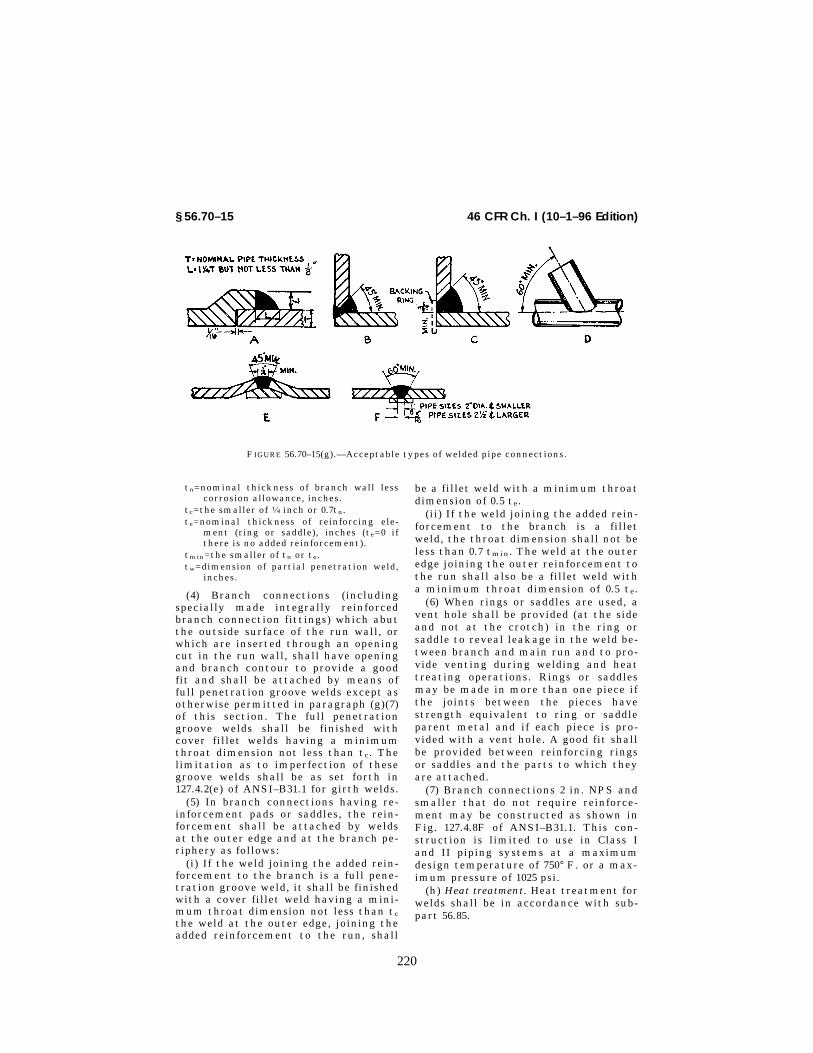
220
46 CFR Ch. I (10–1–96 Edition)§ 56.70–15
FIGURE 56.70–15(g).—Acceptable types of welded pipe connections.
tn=nominal thickness of branch wall lesscorrosion allowance, inches.
tc=the smaller of 1⁄4 inch or 0.7tn.te=nominal thickness of reinforcing ele-
ment (ring or saddle), inches (te=0 ifthere is no added reinforcement).
tmin=the smaller of tn or te.tw=dimension of partial penetration weld,
inches.
(4) Branch connections (includingspecially made integrally reinforcedbranch connection fittings) which abutthe outside surface of the run wall, orwhich are inserted through an openingcut in the run wall, shall have openingand branch contour to provide a goodfit and shall be attached by means offull penetration groove welds except asotherwise permitted in paragraph (g)(7)of this section. The full penetrationgroove welds shall be finished withcover fillet welds having a minimumthroat dimension not less than tc. Thelimitation as to imperfection of thesegroove welds shall be as set forth in127.4.2(e) of ANSI–B31.1 for girth welds.
(5) In branch connections having re-inforcement pads or saddles, the rein-forcement shall be attached by weldsat the outer edge and at the branch pe-riphery as follows:
(i) If the weld joining the added rein-forcement to the branch is a full pene-tration groove weld, it shall be finishedwith a cover fillet weld having a mini-mum throat dimension not less than tc
the weld at the outer edge, joining theadded reinforcement to the run, shall
be a fillet weld with a minimum throatdimension of 0.5 te.
(ii) If the weld joining the added rein-forcement to the branch is a filletweld, the throat dimension shall not beless than 0.7 tmin. The weld at the outeredge joining the outer reinforcement tothe run shall also be a fillet weld witha minimum throat dimension of 0.5 te.
(6) When rings or saddles are used, avent hole shall be provided (at the sideand not at the crotch) in the ring orsaddle to reveal leakage in the weld be-tween branch and main run and to pro-vide venting during welding and heattreating operations. Rings or saddlesmay be made in more than one piece ifthe joints between the pieces havestrength equivalent to ring or saddleparent metal and if each piece is pro-vided with a vent hole. A good fit shallbe provided between reinforcing ringsor saddles and the parts to which theyare attached.
(7) Branch connections 2 in. NPS andsmaller that do not require reinforce-ment may be constructed as shown inFig. 127.4.8F of ANSI–B31.1. This con-struction is limited to use in Class Iand II piping systems at a maximumdesign temperature of 750° F. or a max-imum pressure of 1025 psi.
(h) Heat treatment. Heat treatment forwelds shall be in accordance with sub-part 56.85.
VerDate 27-NOV-96 08:03 Dec 23, 1996 Jkt 167174 PO 00000 Frm 00220 Fmt 8010 Sfmt 8010 E:\CFR\167174.043 167174

221
Coast Guard, DOT § 56.75–20
TABLE 56.70–15 REINFORCEMENT OF GIRTH AND LONGITUDINAL BUTT WELDS
Thickness (in inches) of base metal
Maximum thickness (in inches) of rein-forcement for design temperature
Below 0 °For above750 °F
350° to 750°F
0 °F andabove butless than350 °F
Up to 1⁄8, inclusive ......................................................................................................... 1⁄16 3⁄32 3⁄16
Over 1⁄8 to 3⁄16, inclusive ............................................................................................... 1⁄16 1⁄8 3⁄16
Over 3⁄16 to 1⁄2, inclusive ............................................................................................... 1⁄16 5⁄32 3⁄16
Over 1⁄2 to 1, inclusive ................................................................................................... 3⁄32 3⁄16 3⁄16
Over 1 to 2, inclusive .................................................................................................... 1⁄8 1⁄4 1⁄4Over 2 ............................................................................................................................ 5⁄32 (1 ) (1 )
1 The greater of 1⁄4 in. or 1⁄8 times the width of the weld in inches.
NOTES: 1. For double welded butt joints, this limitation on reinforcement given above applies separately to both inside and out-side surfaces of the joint.
2. For single welded butt joints, the reinforcement limits given above apply to the outside surface of the joint only.3. The thickness of weld reinforcement is based on the thickness of the thinner of the materials being joined.4. The weld reinforcement thicknesses must be determined for the higher of the abutting surfaces involved.5. For boiler external piping use the column titled ‘‘Below 0° F. or above 750° F.’’ for weld reinforcement thicknesses.
[CGFR 68–82, 33 FR 18843, Dec. 18, 1968, as amended by CGFR 69–127, 35 FR 9978, June 17, 1970;CGD 73–254, 40 FR 40165, Sept. 2, 1975; CGD 77–140, 54 FR 40614, Oct. 2, 1989; 55 FR 39969, Oct.1, 1990; CGD 95–012, 60 FR 48050, Sept. 18, 1995]
§ 56.70–20 Qualification, general.(a) Qualification of the welding pro-
cedures to be used, and of the perform-ance of welders and welding operators,is required, and shall comply with therequirements of the ASME Boiler andPressure Vessel Code (section IX) ex-cept as modified by part 57 of this sub-chapter.
(b) Each butt-welded joint of Class Iof Class I–L piping shall be markedwith the welder’s identification sym-bol. Dies shall not be used to mark thepipe where the pressure exceeds 600pounds per square inch or the tempera-ture exceeds 750° F. or in Class I–L sys-tems.
Subpart 56.75—Brazing§ 56.75–5 Filler metal.
(a) The filler metal used in brazingmust be a nonferrous metal or alloyhaving a melting point above 1,000 °F.and below that of the metal beingjoined. The filler metal must meet andflow freely within the desired tempera-ture range and, in conjunction with asuitable flux or controlled atmosphere,must wet and adhere to the surfaces tobe joined. Prior to using a particularbrazing material in a piping system,the requirements of § 56.60–20 of thispart should be considered.
(b) The brazing material used shallhave a shearing strength of at least
10,000 pounds per square inch. The max-imum allowable working pressure forbrazing piping shall be determined bythis part.
(c) (Reproduces 128.1.2.) Fluxes thatare fluid and chemically active at thebrazing temperature shall be used whennecessary to prevent oxidation of thefiller metal and the surfaces to bejoined and to promote free flowing ofthe filler metal.
[CGFR 68–82, 33 FR 18843, Dec. 18, 1968, asamended by CGD 77–140, 54 FR 40615, Oct. 2,1989]
§ 56.75–10 Joint clearance (reproduces128.2.2).
(a) The clearance between surfaces tobe joined shall be no larger than is nec-essary to insure complete capillary dis-tribution of the filler metal; between0.002–inch minimum and 0.006-inchmaximum.
§ 56.75–15 Heating (reproduces128.2.3).
(a) The joint shall be brought tobrazing temperature in as short a timeas possible to minimize oxidation.
§ 56.75–20 Brazing qualification.
(a) The qualification of the perform-ance of brazers and brazing operators,shall be in accordance with the require-ments of part C, section IX of the
VerDate 27-NOV-96 08:03 Dec 23, 1996 Jkt 167174 PO 00000 Frm 00221 Fmt 8010 Sfmt 8010 E:\CFR\167174.043 167174
222
46 CFR Ch. I (10–1–96 Edition)§ 56.75–25
ASME Code and part 57 of this sub-chapter.
(b) Manufacturers shall performthose tests required by paragraph (a) ofthis section prior to performing pro-duction brazing.
§ 56.75–25 Detail requirements.(a) Pipe may be fabricated by brazing
when the temperature to which suchconnections may be subjected does notexceed 425° F. (For exception refer to§ 56.30–30(b)(1).)
(b) (Reproduces 128.2.1.) The surfacesto be brazed shall be clean and freefrom grease, oxides, paint, scale, anddirt of any kind. Any suitable chemicalor mechanical cleaning method may beused to provide a clean wettable sur-face for brazing.
(c) After the parts to be joined havebeen thoroughly cleaned the edges tobe brazed shall be given an even coat-ing of flux prior to heating the joint asa protection against oxidation.
§ 56.75–30 Pipe joining details.(a) Silver brazing. (1) Circumferential
pipe joints may be either of the socketor butt type. When butt joints are em-ployed the edges to be joined shall becut or machined square and the edgesshall be held closely together to insurea satisfactory joint.
(b) Copper-alloy brazing. (1) Copper-alloy brazing may be employed to joinpipe, valves, and fittings. Circumferen-tial joints may be either of the butt orsocket type. Where butt joints are em-ployed, the included angle shall be notless than 90° where the wall thicknessis three-sixteenths of an inch or great-er. The annular clearance of socketjoints shall be held to small clearanceswhich experience indicates is satisfac-tory for the brazing alloy to be em-ployed, method of heating, and mate-rial to be joined. The annular clearanceshall be shown on drawings submittedfor approval of socket joints.
(2) Copper pipe fabricated with longi-tudinal joints for pressures not exceed-ing that permitted by the regulationsin this subchapter may have butt,lapped, or scarfed joints. If of the lattertype, the kerf of the material shall benot less than 60°.
(c) Brazing, general. (1) Heat shall beapplied evenly and uniformly to all
parts of the joint in order to preventlocal overheating.
(2) The members to be joined shall beheld firmly in place until the brazingalloy has set so as to prevent anystrain on the joint until the brazingalloy has thoroughly solidified. Thebrazing shall be done by placing theflux and brazing material on one side ofthe joint and applying heat until thebrazing material flows entirelythrough the lap and shows uniformlyalong the seam on the other side of thejoint. Sufficient flux shall be used tocause the brazing material to appearpromptly after reaching the brazingtemperature.
Subpart 56.80—Bending andForming
§ 56.80–5 Bending.Pipe may be bent by any hot or cold
method and to any radius which willresult in a bend surface free of cracks,as determined by a method of inspec-tion specified in the design, and sub-stantially free of buckles. Such bendsshall meet the design requirements of102.4.5 and 104.2.1 of ANSI–B31.1. Thisshall not prohibit the use of bends de-signed as creased or corrugated. Ifdoubt exists as to the wall thicknessbeing adequate, Class I piping havingdiameters exceeding 4 inches shall benondestructively examined by the useof ultrasonics or other acceptablemethod. Alternatively, the pipe may bedrilled, gaged, and fitted with ascrewed plug extending outside thepipe covering. The nondestructivemethod shall be employed where thedesign temperature exceeds 750° F.Prior to the use of nondestructivemethod of examination by the aboveprocedure, it shall be demonstrated bythe user, in the presence of a marineinspector on specimens similar to thoseto be examined, that consistent re-sults, having an accuracy of plus orminus 3 percent, can be obtained.
[CGFR 68–82, 33 FR 18843, Dec. 18, 1968, asamended by CGFR 69–127, 35 FR 9979, June 17,1970]
§ 56.80–10 Forming (reproduces 129.2).(a) Piping components may be
formed (swaging, lapping, or upsetting
VerDate 27-NOV-96 08:03 Dec 23, 1996 Jkt 167174 PO 00000 Frm 00222 Fmt 8010 Sfmt 8010 E:\CFR\167174.044 167174

223
Coast Guard, DOT § 56.85–10
of pipe ends, extrusion of necks, etc.)by any suitable hot or cold workingmethod, providing such processes re-sult in formed surfaces which are uni-form and free of cracks or other de-fects, as determined by methods of in-spection specified in the design.
§ 56.80–15 Heat treatment of bends andformed components.
(a) (Reproduces 129.3.1.) Carbon steelpiping which has been heated to atleast 1,650° F. for bending or otherforming operations shall require nosubsequent heat treatment.
(b) Ferritic alloy steel piping whichhas been heated for bending or otherforming operations shall receive astress relieving treatment, a full an-neal, or a normalize and temper treat-ment, as specified by the design speci-fication before welding.
(c) (Reproduces 129.3.3.) Cold bendingand forming of carbon steel having awall thickness of three-fourths of aninch and heavier, and all ferritic alloypipe in nominal pipe sizes of 4 inchesand larger, or 1⁄2-inch wall thickness orheavier, shall require a stress relievingtreatment.
(d) (Reproduces 129.3.4.) Cold bendingof carbon and ferritic alloy steel pipein sizes and wall thicknesses less thanspecified in 129.3.3 of ANSI–B31.1 maybe used without a postheat treatment.
(e) (Reproduces 129.3.5.) For other ma-terials the heat treatment of bends andformed components shall be such as toinsure pipe properties that are consist-ent with the original pipe specifica-tion.
(f) All scale shall be removed fromheat treated pipe prior to installation.
(g) (Reproduces 129.3.6.) Austeniticstainless steel pipe that has been heat-
ed for bending or other forming may beused in the ‘‘as-bent’’ condition unlessthe design specification requires postbending heat treatment.
[CGFR 68–62, 33 FR 18843, Dec. 18, 1968, asamended by CGFR 69–127, 35 FR 9979, June 17,1970; CGD 73–254, 40 FR 40166, Sept. 2, 1975]
Subpart 56.85—Heat Treatment ofWelds
§ 56.85–5 Heating and cooling method(reproduces 131.1).
(a) Heat treatment may be accom-plished by a suitable heating methodwhich will provide the desired heatingand cooling rates, the required metaltemperature, metal temperature uni-formity, and temperature control.
§ 56.85–10 Preheating.(a) The minimum preheat tempera-
tures listed in Table 56.85–10 for P-num-ber materials groupings are mandatoryminimum pre-heat temperatures. Pre-heat is required for Class I, I–L, I–N, II–N and II–L piping when the ambienttemperature is below 50° F.
(b) (Modifies 131.2.2.) When weldingdissimilar materials the minimum pre-heat temperature may not be lowerthan the highest temperature listed inTable 56.85–10 for any of the materialsto be welded or the temperature estab-lished in the qualified welding proce-dure.
(c) (Reproduces 131.2.3.) The preheattemperature shall be checked by use oftemperature-indicating crayons, ther-mocouples, pyrometers, or other suit-able methods to assure that the re-quired preheat temperature is obtainedprior to and uniformly maintained dur-ing the welding operation.
TABLE 56.85–10—PREHEAT AND POSTHEAT TREATMENT OF WELDS
ASME Sec IXNos.
Preheat required Post heat treatment requirement (1)(2)
Minimum wall(3)(4) (inch)
Minimum tem-perature
(5)(6)(°F.)
Minimum walland other
(3)(4)(17)(inch)
Temperature(7)(8)(9)(10)(11)(12)(°F.)(inch)
Time cycle
Hour perinch of
wall (3)(4)
Minimumtime within
range(hour)
P–1(16) ........... All .................. 50 (for .30 C.maximum orless) (13).
Over 3⁄4 in ....... 1,100 to 1,200 (minimum)(maximum).
1 1
VerDate 27-NOV-96 08:03 Dec 23, 1996 Jkt 167174 PO 00000 Frm 00223 Fmt 8010 Sfmt 8010 E:\CFR\167174.044 167174

224
46 CFR Ch. I (10–1–96 Edition)§ 56.85–10
TABLE 56.85–10—PREHEAT AND POSTHEAT TREATMENT OF WELDS—Continued
ASME Sec IXNos.
Preheat required Post heat treatment requirement (1)(2)
Minimum wall(3)(4) (inch)
Minimum tem-perature
(5)(6)(°F.)
Minimum walland other
(3)(4)(17)(inch)
Temperature(7)(8)(9)(10)(11)(12)(°F.)(inch)
Time cycle
Hour perinch of
wall (3)(4)
Minimumtime within
range(hour)
P–1(16) ........... All .................. 175 (for over.30 C.) (13)and wallthicknessover 1 in.
......do .............. ......do ...................................... 1 1
P–3(15) ........... All walls ......... 175 ................ Over 1⁄2 in ....... 1,200 to 1,350 (minimum)(maximum).
1 1
P–4(15) ........... Up to 3⁄4 in in-clusive.
300 ................ Over 1⁄2 in orover 4 innom. size or.
1,330 to 1,400 (minimum)(maximum).
1 1
Over 3⁄4 in ...... 400 ................ Over .15 C.maximum.
P–5(15) (lessthan 5 cr.).
Up to 3⁄4 in in-clusive.
300 ................ Over 1⁄2 in orover 4 in.nom. size or.
1,300 to 1,425 (minimum)(maximum).
1 1
Over 3⁄4 in ...... 400 ................ Over 0.15 C.maximum.
P–5(15) (5 cr.and higher).
Up to 3⁄4 inclu-sive.
300 ................ All walls ........... ......do ...................................... 1 2
Over 3⁄4 in ...... 400 ................ Over 0.15 C.maximum.
P–6 .................. All walls ......... 300 (14). ........ All walls ........... 1,400 to 1,500 (minimum)(maximum).
1 2
P–8 .................. ......do ............ None required ......do .............. None required.
For P–7, P–9A, P–9B, P–10C and other mate-rials not listed the Preheat and PostheatTreatment is to be in accordance with thequalified procedure.
Notes Applicable To Table 56.85–10:(1) Not applicable to dissimilar metal
welds.(2) When postheat treatment by annealing
or normalizing is used, the postheat treat-ment temperatures must be in accordancewith the qualified welding procedure.
(3) Wall thickness of a butt weld is definedas the thicker of the two abutting ends afterend preparation including I.D. machining.
(4) The thickness of socket, fillet, and sealwelds is defined as the throat thicknesses forpressure and nonpressure retaining welds.
(5) Preheat temperatures must be checkedby use of temperature indicating crayons,thermocouple pyrometers, or other suitablemethod.
(6) For inert gas tungsten arc root passwelding lower preheat in accordance withthe qualified procedure may be used.
(7) The maximum postheat treatment tem-perature listed for each P number is a rec-ommended maximum temperature.
(8) Postheat treatment temperatures mustbe checked by use of thermocouple pyrom-eters or other suitable means.
(9) Heating rate for furnace, gas, electricresistance, and other surface heating meth-ods must not exceed: (i) 600° F per hour forthicknesses 2 inches and under.
(ii) 600° F per hour divided by 1⁄2 the thick-ness in inches for thickness over 2 inches.
(10) Heating route for induction heatingmust not exceed:
(i) 600° F per hour for thickness less than11⁄2 inches (60 and 400 cycles).
(ii) 500° F per hour when using 60 cyclesand 400° F per hour when using 400 cycles forthicknesses 11⁄2 inches and over.
(11) When local heating is used, the weldmust be allowed to cool slowly from thepostheat treatment temperature. A sug-gested method of retarding cooling is towrap the weld with asbestos and allow tocool in still air. When furnace cooling isused, the pipe sections must be cooled in thefurnace to 1000° F and may then be cooledfurther in still air.
(12) Local postheat treatment of butt weld-ed joints must be performed on a circum-ferential band of the pipe. The minimumwidth of this band, centered on the weld,must be the width of the weld plus 2 inches.
Local postheat treatment of welded branchconnections must be performed by heating acircumferential band of the pipe to which thebranch is welded. The width of the heatedband must extend at least 1 inch beyond theweld joining the branch.
(13) 0.30 C. max applies to specified ladleanalysis.
(14) 600°F maximum interpass temperature.(15) Welding on P–3, P–4, and P–5 with 3 Cr
max. may be interrupted only if—
VerDate 27-NOV-96 08:03 Dec 23, 1996 Jkt 167174 PO 00000 Frm 00224 Fmt 8010 Sfmt 8010 E:\CFR\167174.044 167174

225
Coast Guard, DOT § 56.90–5
(i) At least 3⁄8 inch thickness of weld is de-posited or 25 percent of welding groove isfilled, whichever is greater;
(ii) The weld is allowed to cool slowly toroom temperature; and
(iii) The required preheat is resumed beforewelding is continued.
(16) When attaching welding carbon steelnon-pressure parts to steel pressure partsand the throat thickness of the fillet or par-tial or full penetration weld is 1⁄2 in. or less,postheat treatment of the fillet weld is notrequired for Class I and II piping if preheatto a minimum temperature of 175° F is ap-plied when the thickness of the pressure partexceeds 3⁄4 in.
(17) For Class I–L and II–L piping systems,relief from postweld heat treatment may notbe dependent upon wall thickness. See also§§ 56.50–105(a)(3) and 56.50–105(b)(3) of thischapter.
[CGFR 68–82, 33 FR 18843, Dec. 18, 1968, asamended by CGFR 69–127, 35 FR 9980, June 17,1970; CGD 72–104R, 37 FR 14234, July 18, 1972;CGD 72–206R, 38 FR 17229, June 29, 1973; CGD73–254, 40 FR 40166, Sept. 2, 1975; CGD 77–140,54 FR 40615, Oct. 2, 1989]
§ 56.85–15 Postheat treatment.(a) Where pressure retaining compo-
nents having different thicknesses arewelded together as is often the casewhen making branch connections, thepreheat and postheat treatment re-quirements of Table 56.85–10 apply tothe thicker of the components beingjoined. Postweld heat treatment is re-quired for Classes I, I–L, II–L, and sys-tems. It is not required for Class II pip-ing. Refer to § 56.50–105(a)(3) for excep-tions in Classes I–L and II–L systemsand to paragraph (b) of this section forClass I systems.
(b) All buttwelded joints in Class Ipiping shall be postweld heated as re-quired by Table 56.85–10. The followingexceptions are permitted:
(1) High pressure salt water pipingsystems used in tank cleaning oper-ations; and,
(2) Gas supply piping of carbon orcarbon molybdenum steel used in gasturbines.
(c) All complicated connections in-cluding manifolds shall be stress-re-lieved in a furnace as a whole as re-quired by Table 56.85–10 before beingtaken aboard ship for installation.
(d) (Reproduces 131.3.2.) The postheattreatment method selected for parts ofan assembly shall not adversely affectother components. Heating a fabricated
assembly as a complete unit is usuallydesirable; however, the size or shape ofthe unit or the adverse effect of a de-sired heat treatment on one or morecomponents where dissimilar materialsare involved, may dictate alternativeprocedures such as heating a section ofthe assembly before the attachment ofothers, or local circumferential bandheating of welded joints in accordancewith § 56.85–15(j)(3) and note (12) ofTable 56.85–10.
(e) (Reproduces 131.3.3.) Postheattreatment of welded joints between dis-similar metals having differentpostheat requirements shall be that es-tablished in the qualified welding pro-cedure.
(f)–(h) [Reserved](i) (Reproduces 131.3.4.) For those ma-
terials listed under P–No. 1, when thewall thickness of the thicker of the twoabutting ends, after end preparation, isless than three-fourths inch, the weldneed not be postheat treated. In allcases, where the nominal wall thick-ness is 3⁄4 in. or less, postheat treat-ment is not required.
(j) (1)–(2) [Reserved](3) In local postheat treatment the
entire band must be brought up to uni-form specified temperature over thecomplete circumference of the pipe sec-tion, with a gradual diminishing of thetemperature outward from the edges ofthe band.
[CGFR 68–82, 33 FR 18843, Dec. 18, 1968, asamended by CGD 72–206R, 38 FR 17229, June29, 1973; CGD 73–254, 40 FR 40167, Sept. 2, 1975]
Subpart 56.90—Assembly
§ 56.90–1 General.
(a) The assembly of the various pip-ing components, whether done in ashop or as field erection, shall be doneso that the completely erected pipingconforms with the requirements of theregulations in this subchapter and withthe specified requirements of the engi-neering design.
§ 56.90–5 Bolting procedure.
(a) All flanged joints shall be fittedup so that the gasket contact facesbear uniformly on the gasket and then
VerDate 27-NOV-96 08:03 Dec 23, 1996 Jkt 167174 PO 00000 Frm 00225 Fmt 8010 Sfmt 8010 E:\CFR\167174.044 167174

226
46 CFR Ch. I (10–1–96 Edition)§ 56.90–10
shall be made up with relatively uni-form bolt stress. Bolt loading and gas-ket compression need only be verifiedby touch and visual observation.
(b) (Reproduces 135.2.2.) In boltinggasketed flanged joints, the gasketshall be properly compressed in accord-ance with the design principles applic-able to the type of gasket used.
(c) Steel to cast iron flanged jointsshall be assembled with care to preventdamage to the cast iron flange in ac-cordance with § 56.25–10.
(d) (Reproduces 135.2.4.) All boltsshall be engaged so that there is visibleevidence of complete threadingthrough the nut or threaded attach-ment.
§ 56.90–10 Threaded piping (repro-duces 135.4).
(a) Any compound or lubricant usedin threaded joints shall be suitable forthe service conditions and shall notreact unfavorably with either the serv-ice fluid or the piping materials.
(b) Threaded joints which are to beseal welded shall be made up withoutany thread compound.
(c) Backing off to permit alignmentof pipe threaded joints shall not be per-mitted.
Subpart 56.95—Inspection
§ 56.95–1 General (replaces 136).
(a) The provisions in this subpartshall apply to inspection in lieu of 136of ANSI–B31.1.
(b) Prior to initial operation, a pipinginstallation shall be inspected to theextent necessary to assure compliancewith the engineering design, and withthe material, fabrication, assembly andtest requirements of ANSI–B31.1, asmodified by this subchapter. This in-spection is the responsibility of theowner and may be performed by em-ployees of the owner or of an engineer-ing organization employed by theowner, together with the marine in-spector.
[CGFR 68–82, 33 FR 18843, Dec. 18, 1968, asamended by CGFR 69–127, 35 FR 9979, June 17,1970]
§ 56.95–5 Rights of access of marine in-spectors.
Marine inspectors shall have rightsof access to any place where work con-cerned with the piping is being per-formed. This includes manufacture,fabrication, assembly, erection, andtesting of the piping or system compo-nents. Marine inspectors shall have ac-cess to review all certifications or rec-ords pertaining to the inspection re-quirements of § 56.95–1, including cer-tified qualifications for welders, weld-ing operators, and welding procedures.
§ 56.95–10 Type and extent of examina-tion required.
(a) General. The types and extent ofnondestructive examinations requiredfor piping must be in accordance withthis section and Table 136.4 of ANSI–B31.1. In addition, a visual examinationshall be made.
(1) 100 percent radiography 1 is re-quired for all Class I, I–L and II–L pip-ing equal to or greater than 4 inchesnominal diameter or 0.375 inches nomi-nal wall thickness.
(2) Nondestructive examination is re-quired for all Class II piping equal to orgreater than 18 inches nominal diame-ter regardless or wall thickness. Anytest method acceptable to the Officerin Charge, Marine Inspection may beused.
(3) Appropriate nondestructive ex-aminations of other piping systems arerequired only when deemed necessaryby the Officer in Charge, Marine In-spection. In such cases a method oftesting satisfactory to the Officer inCharge, Marine Inspection must be se-lected from those described in this sec-tion.
(b) Visual examination. Visual exam-ination consists of observation by themarine inspector of whatever portionsof a component or weld are exposed tosuch observation, either before, during,or after manufacture, fabrication, as-sembly or test. All welds, pipe and pip-ing components shall be capable ofcomplying with the limitations on im-perfections specified in the productspecification under which the pipe orcomponent was purchased, or with thelimitations on imperfections specifiedin § 56.70–15(b) (7) and (8), and (c), as ap-plicable.
VerDate 27-NOV-96 08:03 Dec 23, 1996 Jkt 167174 PO 00000 Frm 00226 Fmt 8010 Sfmt 8010 E:\CFR\167174.045 167174
227
Coast Guard, DOT § 56.97–1
1 Where for some reason, such as joint con-figuration, radiography is not applicable, an-other approved examination may be utilized.
(c) Nondestructive types of examina-tions—(1) 100 Percent radiography. Where100 percent radiography 1 is required forwelds in piping, each weld in the pipingshall be completely radiographed. If abutt weld is examined by radiography,for either random or 100 percent radi-ography, the method used shall be asfollows:
(i) X-ray or gamma ray method of ra-diography may be used. The selectionof the method shall be dependent uponits adaptability to the work beingradiographed. The procedure to be fol-lowed shall be as indicated in PW–51 ofsection I of the ASME Code.
(ii) If a piping component or a weldother than a butt weld is radiographed,the method used shall be in accordancewith UW–51 of section VIII of theASME Code.
(2) Random radiography. Where ran-dom radiography 1 is required, one ormore welds may be completely or par-tially radiographed. Random radiogra-phy is considered to be a desirablemeans of spot checking welder per-formance, particularly in field weldingwhere conditions such as position, am-bient temperatures, and cleanliness arenot as readily controlled as in shopwelding. It is to be employed wheneveran Officer in Charge, Marine Inspectionquestions a pipe weld not otherwise re-quired to be tested. The standards ofacceptance are the same as for 100 per-cent radiography.
(3) Ultrasonic. Where 100 percent ul-trasonic testing is specified, the entiresurface of the weld being inspectedshall be covered using extreme careand careful methods to be sure that atrue representation of the actual condi-tions is obtained. The procedures to beused shall be submitted to the Com-mandant for approval.
(4) Liquid penetrant. Where liquid pen-etrant examination is required, the en-tire surface of the weld being examinedshall be covered. The examinationshall be performed in accordance withappendix VIII to section VIII of theASME Code. The following standards ofacceptance shall be met:
(i) All linear discontinuities andaligned penetrant indications revealedby the test shall be removed. Alignedpenetrant indications are those inwhich the average of the center-to-cen-ter distances between any one indica-tion and the two adjacent indicationsin any straight line is less than three-sixteenths inch. All other discontinu-ities revealed on the surface need notbe removed unless the discontinuitiesare also revealed by radiography, inwhich case the pertinent radiographicspecification shall apply.
(5) Magnetic particle. Where magneticparticle testing is required, the entiresurface of the weld being examinedshall be covered. The testing shall beperformed in accordance with appendixVI to section VIII of the ASME Code.The following standards of acceptanceare required for welds. All linear dis-continuities and aligned indications re-vealed by the test shall be removed.Aligned indications are those in whichthe average of the center-to-center dis-tances between any one indication andthe two adjacent indications in anystraight line is less than three-six-teenths inch. All other revealed dis-continuities need not be removed un-less the discontinuities are also re-vealed by radiography, in which casethe requirements of paragraph (c)(1) ofthis section shall be met.
[CGFR 68–82, 33 FR 18843, Dec. 18, 1968, asamended by CGD 72–206R, 38 FR 17229, June29, 1973; CGD 78–108, 43 FR 46546, Oct. 10, 1978;CGD 77–140, 54 FR 40615, Oct. 2, 1989]
Subpart 56.97—Pressure Tests
§ 56.97–1 General (replaces 137).
(a) Scope. The requirements in thissubpart apply to pressure tests of pip-ing in lieu of 137 of ANSI–B31.1. Thoseparagraphs reproduced are so noted.
(b) Leak tightness. It is mandatorythat the design, fabrication and erec-tion of piping constructed under theregulations in this subchapter dem-onstrate leak tightness. Except whereotherwise permitted in this subpart,this requirement must be met by a hy-drostatic leak test prior to initial oper-ations. Where a hydrostatic test is notpracticable, a pneumatic test (§ 56.97–35) or initial service leak test (§ 56.97–
VerDate 27-NOV-96 08:03 Dec 23, 1996 Jkt 167174 PO 00000 Frm 00227 Fmt 8010 Sfmt 8010 E:\CFR\167174.045 167174

228
46 CFR Ch. I (10–1–96 Edition)§ 56.97–5
1 These tests may be made with the itembeing tested partially filled with water, if de-sired.
38) may be substituted if approved bythe Commandant.
(1) At no time during the hydrostatictest may any part of the piping systembe subjected to a stress greater than 90percent of its yield strength (0.2 per-cent offset) at test temperature.
(2) Pneumatic tests may be used inlieu of the required hydrostatic test(except as permitted in paragraph (b)(3)of this section), only when—
(i) Piping subassemblies or systemsare so designed or supported that theycannot be safely filled with water;1 or
(ii) Piping subassemblies or systemsare to be used in services where tracesof the testing medium cannot be toler-ated and, whenever possible, the pipingsubassemblies or system have been pre-viously hydrostatically tested to thepressure required in § 56.97–30(e).
(3) A pneumatic test at a pressurenot to exceed 25 psig may be applied be-fore a hydrostatic or a pneumatic testas a means of locating major leaks.The preliminary pneumatic test mustbe carried out in accordance with therequirements of § 56.97–35.
NOTE: Compressed gas is hazardous whenused as a testing medium. It is, therefore,recommended that special precautions forprotection of personnel be taken whenevergas under pressure is used as the test me-dium.
(4) The hydrostatic test of the pipingsystem, when conducted in accordancewith the requirements of this part, isacceptable as the test for piping sub-assemblies and may also be used in lieuof any such test required by the mate-rial specification for material used inthe piping subassembly or system pro-vided the minimum test pressure re-quired for the piping system is met, ex-cept where the installation would pre-vent performing any nondestructive ex-amination required by the materialspecification to be performed subse-quent to the hydrostatic or pneumatictest.
[CGD 73–254, 40 FR 40167, Sept. 2, 1975]
§ 56.97–5 Pressure testing of non-standard piping system compo-nents.
(a) All nonstandard piping systemcomponents such as welded valves andfittings, nonstandard fittings, mani-folds, seacocks, and other appur-tenances must be hydrostatically test-ed to twice the rated pressure stampedthereon, except that no componentshould be tested at a pressure causingstresses in excess of 90 percent of itsyield strength.
(b) Items for which an acceptedstandard appears in Table 56.60–1(b)need not be tested as described in para-graph (a) of this section, but need onlymeet the test required in the applica-ble standard.
[CGFR 68–82, 33 FR 18843, Dec. 18, 1968, asamended by CGD 77–140, 54 FR 40615, Oct. 2,1989]
§ 56.97–25 Preparation for testing (Re-produces 137.3).
(a) Exposure of joints. All joints in-cluding welds must be left uninsulatedand exposed for examination during thetest.
(b) Addition of temporary supports.Piping systems designed for vapor orgas may be provided with additionaltemporary supports, if necessary, tosupport the weight of the test liquid.
(c) Restraint or isolation of expansionjoints. Expansion joints must be pro-vided with temporary restraint, if re-quired for the additional pressure loadunder test, or they must be isolatedfrom the test.
(d) Isolation of equipment not subjectedto pressure test. Equipment that is notto be subjected to the pressure testmust be either disconnected from thepiping subassembly or system or iso-lated by a blank flange or similarmeans. Valves may be used if the valvewith its closure is suitable for the pro-posed test pressure.
(e) Treatment of flanged joints contain-ing blinds. Flanged joints at whichblinds are inserted to blank off otherequipment during the test need not betested.
(f) Precautions against test medium ex-pansion. If a pressure test is to bemaintained for a period of time and thetest medium in the system is subject tothermal expansion, precautions must
VerDate 27-NOV-96 08:03 Dec 23, 1996 Jkt 167174 PO 00000 Frm 00228 Fmt 8010 Sfmt 8010 E:\CFR\167174.045 167174
229
Coast Guard, DOT § 56.97–35
be taken to avoid excessive pressure. Asmall relief valve set to 11⁄3 times thetest pressure is recommended duringthe pressure test.
[CGD 73–254, 40 FR 40167, Sept. 2, 1975]
§ 56.97–30 Hydrostatic tests (Repro-duces 137.4).
(a) Provision of air vents at high points.Vents must be provided at all highpoints of the piping subassembly orsystem in the position in which thetest is to be conducted to purge airpockets while the component or systemis filling.
(b) Test medium and test temperature.(1) Water will be used for a hydrostaticleak test unless another medium is ap-proved by the Commandant.
(2) The temperature of the test me-dium will be that of the availablesource unless otherwise approved bythe Commandant upon review of themetallurgical aspects of the piping ma-terials with respect to its brittle frac-ture properties.
(c) Check of test equipment before ap-plying pressure. The test equipmentmust be examined before pressure isapplied to ensure that it is tight andthat all low-pressure filling lines andother items that should not be sub-jected to the test pressure have beendisconnected or isolated by valves orother suitable means.
(d) Examination for leakage after appli-cation of pressure. Following the appli-cation of the hydrostatic test pressurefor a minimum of 10 minutes (see§ 56.97–30(g)), examination for leakagemust be made of all joints, connectionsand of all regions of high stress, suchas regions around openings and thick-ness-transition sections.
(e) Minimum required hydrostatic testpressure. Except as otherwise permittedin § 56.97–30(f) or § 56.97–40, piping sys-tems must be subjected to a hydro-static test pressure that at every pointin the system is not less than 1.5 timesthe maximum allowable working pres-sure.
(f) Maximum permissible hydrostatictest pressure. (1) When a system is test-ed hydrostatically, the test pressuremust not exceed the maximum testpressure of any component such as ves-sels, pumps, or valves in the system.
(2) At no time during the hydrostatictest may any part of the piping systembe subjected to a stress greater than 90percent of its yield strength (0.2 per-cent offset) at test temperature.
(g) Hydrostatic test pressure holdingtime. The hydrostatic test pressuremust be maintained for a minimumtotal time of 10 minutes and for suchadditional time as may be necessary toconduct the examination for leakagerequired by § 56.97–30(d).
[CGD 73–254, 40 FR 40167, Sept. 2, 1975]
§ 56.97–35 Pneumatic tests (Replaces137.5).
(a) General Requirements. When apneumatic test is performed, it must beconducted in accordance with the re-quirements of this section.
(b) Test medium and test temperature.(1) The gas used as the test mediummust not be flammable.
(2) The temperature of the test me-dium will be that of the availablesource unless otherwise approved bythe Commandant upon review of themetallurgical aspects of the piping ma-terials with respect to its brittle frac-ture properties.
(c) Check of test equipment before ap-plying pressure. The test equipmentmust be examined before pressure isapplied to ensure that it is tight andthat all items that should not be sub-jected to the test pressure have beendisconnected or isolated by valves orother suitable means.
(d) Procedure for applying pressure.The pressure in the system mustgradually be increased to not morethan one-half of the test pressure, afterwhich the pressure is increased in stepsof approximately one-tenth of the testpressure until the required test pres-sure has been reached.
(e) Examination for leakage after appli-cation of pressure. Following the appli-cation of pressure for the time speci-fied in § 56.97–35(h), examination forleakage in accordance with 56.97–30(d)must be conducted.
(f) Minimum required pneumatic testpressure. Except as provided in § 56.97–35(g) or § 56.97–40, the pneumatic testpressure may not be less than 1.20 normore than 1.25 times the maximum al-lowable working pressure of the pipingsubassembly system.
VerDate 27-NOV-96 08:03 Dec 23, 1996 Jkt 167174 PO 00000 Frm 00229 Fmt 8010 Sfmt 8010 E:\CFR\167174.045 167174

230
46 CFR Ch. I (10–1–96 Edition)§ 56.97–38
(g) Maximum permissible pneumatic testpressure. When a system is tested pneu-matically, the test pressure may notexceed the maximum test pressure ofany component such as vessels, pumpsor valves in the system.
(h) Pneumatic test pressure holdingtime. The pneumatic test pressure mustbe maintained for a minimum totaltime of 10 minutes and for such addi-tional time as may be necessary toconduct the examination for leakagerequired in § 56.97–30(d).
[CGD 73–254, 40 FR 40168, Sept. 2, 1975]
§ 56.97–38 Initial service leak test (Re-produces 137.7).
(a) An initial service leak test and in-spection is acceptable when other typesof test are not practical or when leaktightness is conveniently demonstrabledue to the nature of the service. Oneexample is turbine extraction pipingwhere shut-off valves are not availablefor isolating a line and where tem-porary closures are impractical. Othersmay be systems for service water, lowpressure condensate, plant and instru-ment air, etc., where checking out ofpumps and compressors afford ampleopportunity for leak tightness inspec-tion prior to fullscale operation.
(b) The piping system must be gradu-ally brought up to design pressure.After inspection of the piping systemhas proven that the installation iscomplete and all joints are leak-tight,the piping has met the requirements of§ 56.97–1.
[CGD 73–254, 40 FR 40168, Sept. 2, 1975]
§ 56.97–40 Installation tests.(a) The following piping systems
shall be hydrostatically leak tested inthe presence of a marine inspector at apressure of 11⁄2 times the maximum al-lowable working pressure of the sys-tem:
(1) Class I steam, feedwater, andblowoff piping. Where piping is at-tached to boilers by welding withoutpractical means of blanking off fortesting, the piping shall be subjected tothe same hydrostatic pressure to whichthe boiler is tested. The maximum al-lowable working pressures of boilerfeedwater and blowoff piping shall bethe design pressures specified in
§§ 56.50–30(a)(3) and 56.50–40(b), respec-tively.
(2) Fuel oil discharge piping betweenthe pumps and the burners, but not lessthan 500 pounds per square inch.
(3) High-pressure piping for tankcleaning operations.
(4) Flammable or corrosive liquidsand compressed gas cargo piping, butnot less than 150 pounds per squareinch.
(5) Any Class I, I–L, II–L piping.(6) Cargo oil piping.(7) Firemains, but not less than 150
pounds per square inch.(8) Fuel oil transfer and filling pip-
ing.(9) Class I compressed air piping.(b) Installation testing requirements
for refrigeration, fluid power, and liq-uefied petroleum gas cooking and heat-ing systems may be found in part 58 ofthis subchapter.
(c) Class II piping systems shall betested under working conditions asspecified in the section on initial serv-ice leak test, § 56.97–38.
[CGFR 68–82, 33 FR 18843, Dec. 18, 1968, asamended by CGFR 69–127, 35 FR 9980, June 17,1970; CGD 72–206R, 38 FR 17229, June 29, 1973CGD 73–254, 40 FR 40168, Sept. 2, 1975]
PART 57—WELDING AND BRAZING
Subpart 57.01—Scope
Sec.57.01–1 Qualifications and production tests.
Subpart 57.02—General Requirements
57.02–1 Incorporation by reference.57.02–2 Adoption of section IX of the ASME
Code.57.02–3 Performance qualifications issued by
other agencies.57.02–4 Fabricator’s responsibility.57.02–5 Filler metals.
Subpart 57.03—Procedure Qualifications
57.03–1 General requirements.
Subpart 57.04—Procedure QualificationRange
57.04–1 Test specimen requirements and def-inition of ranges (modifies QW 202, QW210, QW 451, and QB 202).
Subpart 57.05—Performance Qualifications
57.05–1 General.
VerDate 27-NOV-96 08:03 Dec 23, 1996 Jkt 167174 PO 00000 Frm 00230 Fmt 8010 Sfmt 8010 E:\CFR\167174.045 167174