ds31-02 valves and appurtenances mechanical
TRANSCRIPT
Acquisition Group Infrastructure Design Branch
DESIGN STANDARD DS 31-02
Valves and Appurtenances - Mechanical
VERSION 1
REVISION 3
JUNE 2014

Design Standard No. DS 31-02
Valves and Appurtenances - Mechanical
Uncontrolled if Printed Page 2 of 74
Ver 1 Rev 3
© Copyright Water Corporation 2000-2014
FOREWORD
The intent of Design Standards is to specify requirements that assure effective design and delivery of fit for
purpose Water Corporation infrastructure assets for best whole-of-life value with least risk to Corporation
service standards and safety. Design standards are also intended to promote uniformity of approach by asset
designers, drafters and constructors to the design, construction, commissioning and delivery of water
infrastructure and to the compatibility of new infrastructure with existing like infrastructure.
Design Standards draw on the asset design, management and field operational experience gained and
documented by the Corporation and by the water industry generally over time. They are intended for
application by Corporation staff, designers, constructors and land developers to the planning, design,
construction and commissioning of Corporation infrastructure including water services provided by land
developers for takeover by the Corporation.
Nothing in this Design Standard diminishes the responsibility of designers and constructors for applying the
requirements of WA OSH Regulations 1996 (Division 12, Construction Industry – consultation on hazards
and safety management) to the delivery of Corporation assets. Information on these statutory requirements
may be viewed at the following web site location:
http://www.commerce.wa.gov.au/WorkSafe/Content/Industries/Construction/Further_information/National_
standard_for_construction.html
Enquiries relating to the technical content of a Design Standard should be directed to the Principal Engineer,
Mechanical Section, Infrastructure Design Branch. Future Design Standard changes, if any, will be issued to
registered Design Standard users as and when published.
Manager, Infrastructure Design Branch
This document is prepared without the assumption of a duty of care by the Water Corporation. The document is not
intended to be nor should it be relied on as a substitute for professional engineering design expertise or any other
professional advice.
It is the responsibility of the user to ensure they are using the current version of this document.
© Copyright – Water Corporation: This standard and software is copyright. With the exception of use permitted by the
Copyright Act 1968, no part may be reproduced without the written permission of the Water Corporation.
Design Standard No. DS 31-02
Valves and Appurtenances - Mechanical
Uncontrolled if Printed Page 3 of 74
Ver 1 Rev 3
© Copyright Water Corporation 2000-2014
DISCLAIMER
This Standard is intended solely for application to the acquisition of water infrastructure in Operating Areas in
Western Australia where the Water Corporation has been licensed to provide water services subject to the terms
and conditions of its Operating License.
This Standard is provided for use only by a suitably qualified professional design engineer who shall apply the
skill, knowledge and experience necessary to understand the risks involved and undertake all infrastructure design
and installation specification preparation work.
Any interpretation of anything in this Standard that deviates from the requirements specified in the project design
drawings and construction specifications shall be resolved by reference to and determination by the design
engineer.
The Corporation accepts no liability for any loss or damage that arises from anything in the Standard including
loss or damage that may arise due to the errors and omissions of any person.

Design Standard No. DS 31-02
Valves and Appurtenances - Mechanical
Uncontrolled if Printed Page 4 of 74
Ver 1 Rev 3
© Copyright Water Corporation 2000-2014
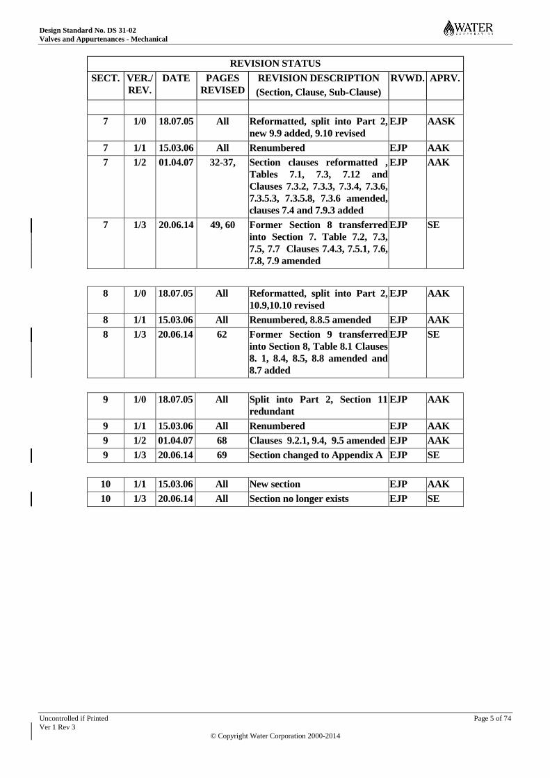
REVISION STATUS
The revision status of this standard is shown section by section below:
REVISION STATUS
SECT. VER./
REV.
DATE PAGES
REVISED
REVISION DESCRIPTION
(Section, Clause, Sub-Clause)
RVWD. APRV.
1 1/0 18.07.05 All Reformatted, split into Part 2 EJP AAK
1 1/1 15.03.06 11, 12 Sections 1 & 2 amalgamated EJP AAK
1 1/2 01.04.07 10 Clause 1.2 amended EJP AAK
1 1/3 20.06.14 12 Clauses 1.1 – 1.7 amended EJP SE
2 1/0 18.07.05 All Reformatted, split into Part 2 EJP AAK
2 1/1 15.03.06 All Renumbered, 2.7 added EJP AAK
2 1/3 20.06.14 14-16 Former Sections 2 and 3
amalgamated Clauses 2.1 - 2.5,
2.8, 2.10, 2.11 amended or
added
EJP SE
3 1/0 18.07.05 All Reformatted, split into Part 2,
Section 5 revised
EJP AAK
3 1/1 15.03.06 All Renumbered EJP AAK
3 1/2 01.04.07 16 Section 3 amended EJP AAK
3 1/3 20.06.14 20 Former Section 4 transferred
into Section 3, Clause 3.4.3(i)
and Table 3.2 amended
EJP SE
4 1/0 18.07.05 All Reformatted, split into Part 2,
6.2 revised
EJP AAK
4 1/1 15.03.06 All Renumbered EJP AAK
4 1/2 01.04.07 19, 21 4.4.1(g) added, formula, clause
4.8 amended
EJP AAK
4 1/3 20.06.14 23 - 26 Former Section 5 transferred
into Section 4
EJP SE
5 1/0 18.07.05 All Reformatted, split into Part 2,
7.4.3 revised
EJP AAK
5 1/1 15.03.06 All Renumbered EJP AAK
5 1/3 20.06.14 27 - 29 Former Section 6 transferred
into Section 5, Heading, Clause
5.1, 5.2, 5.4.2, 5.5.2, 5.6
amended
EJP SE
6 1/0 18.07.05 All Reformatted, split into Part 2 EJP AAK
6 1/1 15.03.06 All Renumbered EJP AAK
6 1/3 20.06.14 31` - 47 Former Section 7 transferred
into Section 6, Table 6.1,
Clauses, 6.3, 6.5 - 6.10
amended
EJP SE
Design Standard No. DS 31-02
Valves and Appurtenances - Mechanical
Uncontrolled if Printed Page 5 of 74
Ver 1 Rev 3
© Copyright Water Corporation 2000-2014
REVISION STATUS
SECT. VER./
REV.
DATE PAGES
REVISED
REVISION DESCRIPTION
(Section, Clause, Sub-Clause)
RVWD. APRV.
7 1/0 18.07.05 All Reformatted, split into Part 2,
new 9.9 added, 9.10 revised
EJP AASK
7 1/1 15.03.06 All Renumbered EJP AAK
7 1/2 01.04.07 32-37, Section clauses reformatted ,
Tables 7.1, 7.3, 7.12 and
Clauses 7.3.2, 7.3.3, 7.3.4, 7.3.6,
7.3.5.3, 7.3.5.8, 7.3.6 amended,
clauses 7.4 and 7.9.3 added
EJP AAK
7 1/3 20.06.14 49, 60 Former Section 8 transferred
into Section 7. Table 7.2, 7.3,
7.5, 7.7 Clauses 7.4.3, 7.5.1, 7.6,
7.8, 7.9 amended
EJP SE
8 1/0 18.07.05 All Reformatted, split into Part 2,
10.9,10.10 revised
EJP AAK
8 1/1 15.03.06 All Renumbered, 8.8.5 amended EJP AAK
8 1/3 20.06.14 62 Former Section 9 transferred
into Section 8, Table 8.1 Clauses
8. 1, 8.4, 8.5, 8.8 amended and
8.7 added
EJP SE
9 1/0 18.07.05 All Split into Part 2, Section 11
redundant
EJP AAK
9 1/1 15.03.06 All Renumbered EJP AAK
9 1/2 01.04.07 68 Clauses 9.2.1, 9.4, 9.5 amended EJP AAK
9 1/3 20.06.14 69 Section changed to Appendix A EJP SE
10 1/1 15.03.06 All New section EJP AAK
10 1/3 20.06.14 All Section no longer exists EJP SE
Design Standard No. DS 31-02
Valves and Appurtenances - Mechanical
Uncontrolled if Printed Page 6 of 74
Ver 1 Rev 3
© Copyright Water Corporation 2000-2014
DESIGN STANDARD DS 31-02 Valves and Appurtenances - Mechanical
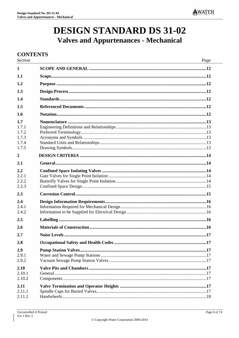
CONTENTS Section Page
1 SCOPE AND GENERAL .......................................................................................................... 12
1.1 Scope............................................................................................................................................ 12
1.2 Purpose ....................................................................................................................................... 12
1.3 Design Process ............................................................................................................................ 12
1.4 Standards .................................................................................................................................... 12
1.5 Referenced Documents .............................................................................................................. 12
1.6 Notation ....................................................................................................................................... 12
1.7 Nomenclature ............................................................................................................................. 13 1.7.1 Engineering Definitions and Relationships ................................................................................. 13 1.7.2 Preferred Terminology ................................................................................................................. 13 1.7.3 Acronyms and Symbols ............................................................................................................... 13 1.7.4 Standard Units and Relationships ................................................................................................ 13 1.7.5 Drawing Symbols ......................................................................................................................... 13
2 DESIGN CRITERIA .................................................................................................................. 14
2.1 General ........................................................................................................................................ 14
2.2 Confined Space Isolating Valves .............................................................................................. 14 2.2.1 Gate Valves for Single Point Isolation ........................................................................................ 14 2.2.2 Butterfly Valves for Single Point Isolation.................................................................................. 14 2.2.3 Confined Space Design ................................................................................................................ 15
2.3 Corrosion Control ...................................................................................................................... 15
2.4 Design Information Requirements ........................................................................................... 16 2.4.1 Information Required for Mechanical Design ............................................................................. 16 2.4.2 Information to be Supplied for Electrical Design ........................................................................ 16
2.5 Labelling ..................................................................................................................................... 16
2.6 Materials of Construction ......................................................................................................... 16
2.7 Noise Levels ................................................................................................................................ 17
2.8 Occupational Safety and Health Codes ................................................................................... 17
2.9 Pump Station Valves .................................................................................................................. 17 2.9.1 Water and Sewage Pump Stations ............................................................................................... 17 2.9.2 Vacuum Sewage Pump Station Valves ........................................................................................ 17
2.10 Valve Pits and Chambers .......................................................................................................... 17 2.10.1 General ......................................................................................................................................... 17 2.10.2 Components ................................................................................................................................. 17
2.11 Valve Termination and Operator Heights .............................................................................. 17 2.11.1 Spindle Caps for Buried Valves................................................................................................... 17 2.11.2 Handwheels .................................................................................................................................. 18

Design Standard No. DS 31-02
Valves and Appurtenances - Mechanical
Uncontrolled if Printed Page 7 of 74
Ver 1 Rev 3
© Copyright Water Corporation 2000-2014
2.12 Vibration ..................................................................................................................................... 18
3 AIR VALVES .............................................................................................................................. 19
3.1 Air or Gas Entrapment ............................................................................................................. 19
3.2 Causes of Air or Gas Entrapment ............................................................................................ 19
3.3 Air Release and Vacuum Break Valves ................................................................................... 20
3.4 Design Criteria ........................................................................................................................... 20 3.4.1 Kinetic and Non-slam Valves ...................................................................................................... 20 3.4.2 Air Valve Performance Factors ................................................................................................... 21
3.4.2.1 Pipeline fill rate ............................................................................................................ 21 3.4.2.2 Pipeline filling differential ........................................................................................... 21 3.4.2.3 Pipeline emptying differential ...................................................................................... 21 3.4.2.4 Air valve sizing ............................................................................................................. 21 3.4.2.5 Full bore or reduced bore air valves ............................................................................. 22
3.4.3 Conditions Requiring Air Valves ................................................................................................ 22 3.4.4 Air Valve Sizing .......................................................................................................................... 23
3.5 Summary of Air Valve Data ..................................................................................................... 24
3.6 Water Applications .................................................................................................................... 24 3.6.1 Water Type Air Valves ................................................................................................................ 24 3.6.2 Isolating Valves ........................................................................................................................... 24
3.7 Sewage Applications .................................................................................................................. 25 3.7.1 Sewage Air Valves ....................................................................................................................... 25 3.7.2 Water Type Air Valves in Sewage Applications ......................................................................... 25 3.7.3 Manual Release and Air Valves................................................................................................... 25 3.7.4 Air Valve Isolating Valves........................................................................................................... 25
3.8 Location of Air Valves ............................................................................................................... 25 3.8.1 Air Valve Pits ............................................................................................................................... 25 3.8.2 Above Ground Air Valves ........................................................................................................... 25
4 BACKFLOW PREVENTION DEVICES ................................................................................ 26
4.1 General ........................................................................................................................................ 26
4.2 Cross Connection ....................................................................................................................... 26
4.3 Hazard Ratings........................................................................................................................... 26 4.3.1 High Hazard ................................................................................................................................. 26 4.3.2 Medium Hazard ........................................................................................................................... 26 4.3.3 Low Hazard .................................................................................................................................. 26
4.4 Levels of Backflow Protection .................................................................................................. 26 4.4.1 Individual ..................................................................................................................................... 27 4.4.2 Zone ............................................................................................................................................. 27 4.4.3 Containment ................................................................................................................................. 27
4.5 Backflow Prevention Devices .................................................................................................... 27 4.5.1 General ......................................................................................................................................... 27 4.5.2 Standards ...................................................................................................................................... 27 4.5.3 Field Testing and Maintainability ................................................................................................ 27 4.5.4 Devices Overview ........................................................................................................................ 28
Design Standard No. DS 31-02
Valves and Appurtenances - Mechanical
Uncontrolled if Printed Page 8 of 74
Ver 1 Rev 3
© Copyright Water Corporation 2000-2014
5 FLOW REGULATING VALVES ............................................................................................. 29
5.1 General ........................................................................................................................................ 29
5.2 Valve Pits and Chambers .......................................................................................................... 29
5.3 Automatic Control Valves ......................................................................................................... 29
5.4 Pressure Reducing Valves ......................................................................................................... 29 5.4.1 General ......................................................................................................................................... 29 5.4.2 Design Requirements ................................................................................................................... 29 5.4.3 Pipework Layout and Ancillaries ................................................................................................ 30
5.5 Pressure Sustaining Valves ....................................................................................................... 30 5.5.1 General ......................................................................................................................................... 30 5.5.2 Design Requirements ................................................................................................................... 30 5.5.3 Pipework Layout and Ancillaries ................................................................................................ 30
5.6 Pressure Reducing and Sustaining Valve Data ....................................................................... 31
5.7 Inline Regulating Valves ........................................................................................................... 31 5.7.1 Inline Regulating Valves (IRV) Design Issues ............................................................................ 31
5.8 Discharge Regulating Valve ...................................................................................................... 32
6 ISOLATING VALVES ............................................................................................................... 33
6.1 Application and Suitability of Isolating Valves ...................................................................... 33
6.2 Ball Valves .................................................................................................................................. 33 6.2.1 General ......................................................................................................................................... 33 6.2.2 Design Data and Specification ..................................................................................................... 33
6.3 Butterfly Valves ......................................................................................................................... 34 6.3.1 General ......................................................................................................................................... 34 6.3.2 Types ............................................................................................................................................ 34 6.3.3 Design Features ............................................................................................................................ 36 6.3.4 Butterfly Valve Design Constraints ............................................................................................. 36 6.3.5 Wafer and Lugged Butterfly Valves ............................................................................................ 36 6.3.6 Double Flanged Seal-on-Body (SOB) Butterfly Valves .............................................................. 37 6.3.7 High Performance Butterfly Valves............................................................................................. 38 6.3.8 Guard Valves ............................................................................................................................... 38
6.3.8.1 General ......................................................................................................................... 38 6.3.8.2 Risk Potential................................................................................................................ 38 6.3.8.3 Valve Types .................................................................................................................. 38 6.3.8.4 Seal-On-Body Butterfly Valves .................................................................................... 39 6.3.8.5 Seal-On-Disc Butterfly Valves ..................................................................................... 39
6.3.9 Direction of Rotation for Closure ................................................................................................ 39
6.4 Diaphragm Valves ...................................................................................................................... 40 6.4.1 General ......................................................................................................................................... 40 6.4.2 Data and Specification ................................................................................................................. 40
6.5 Gate Valves for General Purposes ........................................................................................... 40 6.5.1 General ......................................................................................................................................... 40 6.5.2 Design Requirements ................................................................................................................... 41 6.5.3 Data and Specification ................................................................................................................. 41
6.6 Gate Valves for Waterworks Purposes .................................................................................... 41 6.6.1 General ......................................................................................................................................... 41 6.6.2 Valve Orientation ......................................................................................................................... 42 6.6.3 Buried Gate Valves ...................................................................................................................... 42
Design Standard No. DS 31-02
Valves and Appurtenances - Mechanical
Uncontrolled if Printed Page 9 of 74
Ver 1 Rev 3
© Copyright Water Corporation 2000-2014
6.6.4 Metal Seated Gate Valves ............................................................................................................ 42 6.6.5 Resilient Seated Gate Valves ....................................................................................................... 42 6.6.6 Direction of Rotation for Closure ................................................................................................ 43 6.6.7 Unbalanced Head Limits.............................................................................................................. 43 6.6.8 Gate Valve Gearing...................................................................................................................... 44 6.6.9 Data and Specification ................................................................................................................. 44
6.7 Globe Valves ............................................................................................................................... 45 6.7.1 General ......................................................................................................................................... 45 6.7.2 Design Requirements ................................................................................................................... 45 6.7.3 Data and Specification ................................................................................................................. 45
6.8 Knife Gate Valves ...................................................................................................................... 46 6.8.1 General ......................................................................................................................................... 46 6.8.2 Design Requirements ................................................................................................................... 46 6.8.3 Data and Specification ................................................................................................................. 46
6.9 Plug Valves ................................................................................................................................. 47 6.9.1 General ......................................................................................................................................... 47 6.9.2 Data and Specification ................................................................................................................. 47
6.10 Pump Station Isolating Valves .................................................................................................. 48
7 NON-RETURN VALVES .......................................................................................................... 49
7.1 Non-Return Valve Applications and Suitability ..................................................................... 49 7.1.1 General ......................................................................................................................................... 49 7.1.2 Slamming of Non-Return Valves ................................................................................................. 49
7.2 Cone and Diaphragm Non-Return Valve ................................................................................ 50 7.2.1 General ......................................................................................................................................... 50 7.2.2 Application ................................................................................................................................... 50 7.2.3 Features ........................................................................................................................................ 50 7.2.4 Design Criteria ............................................................................................................................. 50
7.3 Damped Swing Check Non-Return Valves .............................................................................. 51
7.4 Dual Plate (Flap) Non-Return Valve ........................................................................................ 51 7.4.1 General ......................................................................................................................................... 51 7.4.2 Specification ................................................................................................................................ 51 7.4.3 Applications ................................................................................................................................. 51 7.4.4 Features ........................................................................................................................................ 51 7.4.5 Materials ...................................................................................................................................... 52 7.4.6 Design Criteria ............................................................................................................................. 52
7.5 Lift Type Non-Return Valve ..................................................................................................... 53 7.5.1 General ......................................................................................................................................... 53 7.5.2 Specification ................................................................................................................................ 53 7.5.3 Application ................................................................................................................................... 53 7.5.4 Features ........................................................................................................................................ 53 7.5.5 Design Criteria ............................................................................................................................. 54
7.6 Rapid Response Non-Return Valve .......................................................................................... 54 7.6.1 General ......................................................................................................................................... 54 7.6.2 Specification ................................................................................................................................ 55 7.6.3 Application ................................................................................................................................... 55 7.6.4 Features ........................................................................................................................................ 55 7.6.5 Design Criteria ............................................................................................................................. 55 7.6.6 Valve Selection ............................................................................................................................ 56
7.6.6.1 Flow Velocities ............................................................................................................. 56
Design Standard No. DS 31-02
Valves and Appurtenances - Mechanical
Uncontrolled if Printed Page 10 of 74
Ver 1 Rev 3
© Copyright Water Corporation 2000-2014
7.6.6.2 Dynamic Response ....................................................................................................... 57 7.6.6.3 Acceptable Reverse Velocities ..................................................................................... 57
7.7 Single-Spring Flap Type Non-Return Valve ........................................................................... 58 7.7.1 General ......................................................................................................................................... 58 7.7.2 Applications ................................................................................................................................. 58 7.7.3 Materials ...................................................................................................................................... 59 7.7.4 Design Criteria ............................................................................................................................. 59
7.8 Swing Check Non-Return Valve ............................................................................................... 59 7.8.1 General ......................................................................................................................................... 59 7.8.2 Specification ................................................................................................................................ 59 7.8.3 Application ................................................................................................................................... 59 7.8.4 Features ........................................................................................................................................ 60 7.8.5 Design Criteria ............................................................................................................................. 60
7.9 Tilting Disc Non-Return Valve ................................................................................................. 61 7.9.1 General ......................................................................................................................................... 61 7.9.2 Specification ................................................................................................................................ 61 7.9.3 Application ................................................................................................................................... 61 7.9.4 Features ........................................................................................................................................ 61 7.9.5 Design Criteria ............................................................................................................................. 62
8 MISCELLANEOUS VALVES AND APPURTENANCES ..................................................... 63
8.1 Air Vent....................................................................................................................................... 63
8.2 Bypass Valves ............................................................................................................................. 63 8.2.1 External Bypass ........................................................................................................................... 63 8.2.2 Integral Bypass Valves ................................................................................................................ 63
8.3 Fire Hydrants ............................................................................................................................. 64 8.3.1 General ......................................................................................................................................... 64 8.3.2 Screw Down Versus Spring Hydrants ......................................................................................... 64 8.3.3 Specification ................................................................................................................................ 64 8.3.4 Applications ................................................................................................................................. 64
8.4 Magnetic Flowmeters ................................................................................................................ 64
8.5 Mechanical Flowmeters............................................................................................................. 65 8.5.1 General ......................................................................................................................................... 65 8.5.2 Volumetric Chamber Meters ....................................................................................................... 65 8.5.3 Helical Vane Meters .................................................................................................................... 65
8.6 Level Control Ball Float Valves ................................................................................................ 66
8.7 Bourdon Tube Pressure Gauges for Water Service ............................................................... 66 8.7.1 General ......................................................................................................................................... 66 8.7.2 Technical requirements ................................................................................................................ 66
8.8 Penstocks ..................................................................................................................................... 67 8.8.1 General ......................................................................................................................................... 67 8.8.2 Penstock Types ............................................................................................................................ 67 8.8.3 Design Criteria ............................................................................................................................. 67 8.8.4 Reference Standards .................................................................................................................... 68
8.9 Scour Valves ............................................................................................................................... 68 8.9.1 General ......................................................................................................................................... 68 8.9.2 Valve Sizing and Specification .................................................................................................... 68
8.10 Vacuum Interface Valve ............................................................................................................ 69 8.10.1 General ......................................................................................................................................... 69
Design Standard No. DS 31-02
Valves and Appurtenances - Mechanical
Uncontrolled if Printed Page 11 of 74
Ver 1 Rev 3
© Copyright Water Corporation 2000-2014
8.10.2 Features ........................................................................................................................................ 69 8.10.3 Specification ................................................................................................................................ 69
9 APPENDIX A: BUTTERFLY CAVITATION ........................................................................ 70
9.1 Butterfly Valve Cavitation (Informative) ................................................................................ 70 9.1.1 General ......................................................................................................................................... 70 9.1.2 Valve Diameter Equal to Pipe Diameter ...................................................................................... 70 9.1.3 Valve Diameter Equal to 75% Pipe Diameter ............................................................................. 71 9.1.4 Maximum Opening Angle and Differential Head Relationship .................................................. 72
Design Standard No. DS 31-02
Valves and Appurtenances - Mechanical
Uncontrolled if Printed Page 12 of 74
Ver 1 Rev 3
© Copyright Water Corporation 2000-2014
1 SCOPE AND GENERAL
1.1 Scope
Design Standard DS 31-02 is the second part of a two part standard which provides design
requirements for pipework valves and appurtenances. The first part of the Standard comprises:
DS 31-01 Pipework – Mechanical
Design Standard DS 31-02 sets out the Corporation’s mechanical standards, guidelines and preferred
engineering practices for design of valves and appurtenances used in water supply and sewage
infrastructure.
This Standard is not intended for gas and high temperature or steam applications.
1.2 Purpose
The Corporation’s mechanical design standards are documented in its DS 30 Standards series.
Designers shall comply with these standards for the design and specification of mechanical
components of assets being acquired for the Corporation.
The purpose of the DS 30 Standards series is to provide:
(a) Standards and guidelines applicable in the design of Corporation assets,
(b) Explanatory or specific design information,
(c) Information relating to Corporation preferences and practices which have evolved from over a
century of experience in the water industry.
1.3 Design Process
The Designer shall comply with the requirements of the relevant mechanical design process contained
in DS 30.
1.4 Standards
All materials and workmanship shall comply with latest revisions of the relevant codes and standards.
Water Corporation Strategic Product Specifications (SPS), or in their absence the latest editions of
Australian Standards, or Water Services Association of Australia (WSAA) Codes, shall be referenced
for design and specification. In the absence of relevant Australian Standards or WSAA Codes,
relevant international or industry standards shall be referenced.
1.5 Referenced Documents
Corporation Standards and Specifications, and Australian Standards and International Standards
referred to throughout this document are listed in full in Appendices A and B of DS 30-01.
1.6 Notation
Statements governed by the use of the word ‘shall’ are mandatory or ‘normative’ requirements of the
Standard. Statements expressed by the use of the words ‘should” or ‘may” are ‘informative’ but not
mandatory and are provided for information and guidance. Notes in the Standard text are informative.
Notes forming part of Standard Tables are normative
Design Standard No. DS 31-02
Valves and Appurtenances - Mechanical
Uncontrolled if Printed Page 13 of 74
Ver 1 Rev 3
© Copyright Water Corporation 2000-2014
1.7 Nomenclature
1.7.1 Engineering Definitions and Relationships
Definitions relating to terminology used in the DS 30 Standard series are contained in section 2
‘Engineering Definitions and Relationships’ of DS 30-01.
1.7.2 Preferred Terminology
For the preferred terms to be used in designs the reader is referred to the Preferred Terminology
section of DS 30-01.
1.7.3 Acronyms and Symbols
For abbreviations referred to in this Standard the reader is referred to the Acronyms section of DS 30-
01.
1.7.4 Standard Units and Relationships
The units and relationships used for mechanical designs based on this standard shall be in accordance
with those specified in the SI Units, Relationships and Prefixes section of DS 30-01.
1.7.5 Drawing Symbols
A comprehensive list of mechanical drawing symbols for pipework and valves is referenced in DS 80.
Design Standard No. DS 31-02
Valves and Appurtenances - Mechanical
Uncontrolled if Printed Page 14 of 74
Ver 1 Rev 3
© Copyright Water Corporation 2000-2014
2 DESIGN CRITERIA
2.1 General
This section details the design criteria that should be applied (where relevant) during the design of
pump stations and is arranged in alphabetic order for referencing convenience. It also includes
explanatory notes and information both for record purposes and assistance to the reader. In addition to
the following design criteria, the Designer shall also refer to relevant parts of DS 30, DS 30-01, DS
30-02, DS 31-01, DS 31-02, DS 32-01, DS 32-02, DS 35, DS 38-01 and DS 38-02.
Consideration shall be given (but not restricted) to the following.
2.2 Confined Space Isolating Valves
Design involving confined spaces that personnel are required to access shall take into account the
specific requirements detailed in the Confined Space section of DS 30-02. These cover the relevant
standards and procedures applicable to operational practices. Additionally the following information
relates to confined spaces within water pipelines with respect to their isolating valves and
recommended design strategies.
NOTE: The following information is based on an investigation commissioned by the Corporation and subsequent
report “Confined Space Entry – Single Point Isolation Devices” dated January 2000.
2.2.1 Gate Valves for Single Point Isolation
Gate valves for waterworks purposes may be considered as adequate single point isolation devices
provided the following factors are taken into account:
(a) That new valves are selected correctly for the application and properly engineered in
accordance with the appropriate standards.
(b) That a site assessment be conducted for potential problems that may occur with the operation of
existing aged valves.
(c) A locking device shall be employed on the input shaft of gate valves to provide a lockable
fixture and prevent inadvertent opening.
(d) Proper operational practices are observed in terms of:
(i) job safety and risk analysis;
(ii) implementation of proper operation strategies including assessment of all pressure
containing valves;
(iii) removal of all air valves (to eliminate possibility of air valve ‘hang up’ supporting a
column of water); and
(iv) closure and tagging of all relevant valves in the system.
2.2.2 Butterfly Valves for Single Point Isolation
Double Flanged butterfly valves for waterworks purposes may be considered as adequate single point
isolation devices provided the following factors are taken into account:
(a) There exists the perception that a butterfly valve does not provide the same level of security as
a gate valve and that is not supported in reality (refer Note).
(b) Contrary to the perception a butterfly disc cannot ‘run open’. This is because the valve requires
external assistance to overcome the sealing resistance, which is higher than the hydrostatic
torque. Also the disc cannot drive the actuator gear train in order to allow it to open because of
the high gearing and self-locking characteristics of the worm and quadrant.
Design Standard No. DS 31-02
Valves and Appurtenances - Mechanical
Uncontrolled if Printed Page 15 of 74
Ver 1 Rev 3
© Copyright Water Corporation 2000-2014
(c) Shaft and disc pins failure is negligible risk. The shaft is designed for torque and accordingly
has a large safety factor in shear (the failure scenario of most concern). Also, the disc pins also
have a generous safety factor. Neither would be subject to failure once the valve was in the
closed position.
(d) That new valves are selected correctly for the application and properly engineered in
accordance with the appropriate standards.
(e) That a site assessment be conducted for potential problems that may occur with the operation of
existing aged valves.
(f) A locking device shall be employed on the input shaft of the butterfly valve, to provide a
lockable fixture and prevent inadvertent opening of the valve.
(g) Proper operational practices are observed in terms of:
(i) job safety and risk analysis;
(ii) implementation of proper operation strategies including assessment of all pressure
containing valves;
(iii) removal of all air valves (to eliminate possibility of air valve ‘hang up’ supporting a
column of water); and
(iv) closure and tagging of all relevant valves in the system.
NOTE: Ignoring the perception issue, a seal-on-body butterfly valve unlike a gate valve or seal-on-disc
butterfly valve should not suffer corrosion over time because the internal wetted surfaces are
corrosion resistant so that a high level of confidence in its security could be extended over an
indefinite period of time, provided that periodic inspection and maintenance is undertaken.
2.2.3 Confined Space Design
Summarising, the following issues should be addressed in dealing with confined space:
(a) Compulsory locking devices on input shafts of all valves shall be incorporated into all new
valves regardless of whether they are non buried or buried e.g. use of padlockable fittings on
the input spindles of the valves.
(b) Ensure that the requirement to include a self-locking worm and quadrant type gearbox is
included in all butterfly valve specifications.
(c) Specify ductile iron in lieu of cast iron for gate and seal-on-disc butterfly valves with polymeric
coatings with corrosion mitigation strategies via sealing of threads and dissimilar metal
interfaces to prevent galvanic corrosion.
(d) Where practicable seal-on-body butterfly valves of ductile iron body construction shall be the
preferred selection over seal-on-disc butterfly valves and gate valves because of its simplicity,
superior corrosion resistant characteristics and lower head loss.
(e) If seal-on-disc butterfly valves are required then the disc material shall either be DI coated as
required by SPS 262 or of corrosion resistant material. Where the valve seat is of ‘rolled-in’
design, the void must be full sealed.
(f) New distribution network designs should address issues of confined space isolation wherever
practicable. The key strategy in the design should always be to eliminate confined space entry
by personnel where possible.
2.3 Corrosion Control
For general information on coatings and corrosion mitigation the Designer should refer to the Coating
and Corrosion sections of DS 30-02. For more information on coatings refer to DS 95.
Design Standard No. DS 31-02
Valves and Appurtenances - Mechanical
Uncontrolled if Printed Page 16 of 74
Ver 1 Rev 3
© Copyright Water Corporation 2000-2014
2.4 Design Information Requirements
Pipe and pipework design shall be in accordance with AS 4041 and relevant Corporation standards.
2.4.1 Information Required for Mechanical Design
Information required for mechanical design is contained in DS 30 (Clause 3.3.4) and the following (as
applicable):
(a) Fluid type and characteristics e.g. temperature, corrosivity, hazard level e.g. acids or fuel oil,
and water quality
(b) Pipeline size
(c) Initial and future pipeline flow rates (L/s or ML/d)
(d) Initial and future pipeline upstream and downstream heads (m)
(e) Maximum allowable shutdown hours
(f) Alternative modes of operation; e.g. local, remote, electric/manual over-ride etc
(g) Required closing time
(h) Type of actuator required e.g. lever, ungeared, geared, electric actuator, pneumatic actuator,
hydraulic actuator etc
(i) Whether buried, pit (chamber) or above-ground
(j) Environment:
(iii) corrosivity of atmosphere or soils
(iv) sunlight effect e.g. detrimental to some plastic pipe material
(v) effect of immersion by ground water
(vi) potential presence of hydrocarbons or hydrocarbon based products e.g. which could taint
potable water if using PE, PB or PVC pipe
(vii) ambient temperature variation for expansion considerations
(viii) wind effects on suspended pipe
(ix) ground characteristics e.g. under road crossings, creek crossings, unstable soils; etc
(x) presence of bushfires in remote locations
(xi) contact with dissimilar pipework materials e.g. galvanic corrosion potential
2.4.2 Information to be Supplied for Electrical Design
Information to be supplied for electrical design is contained in DS 30 (Clause 3.3.4).
2.5 Labelling
All valves shall be properly identified and labeled in accordance with the Signage and Labels section
of DS 30-02. This particularly includes key operated buried service by-pass gate valves and buried
service butterfly valves, which shall be labeled on the top of their covers.
2.6 Materials of Construction
For general information and materials of construction requirements refer to the Materials section of
DS 30-01.
Design Standard No. DS 31-02
Valves and Appurtenances - Mechanical
Uncontrolled if Printed Page 17 of 74
Ver 1 Rev 3
© Copyright Water Corporation 2000-2014
2.7 Noise Levels
Valves shall comply with the noise level requirements contained in DS 30-02 for:
(a) daily noise dose for personnel, and
(b) neighbourhood noise levels e.g. environmental noise.
2.8 Occupational Safety and Health Codes
The Designer shall comply with occupational safety and health codes in accordance with the
requirements set out in the Occupational Safety and Health section of DS 30-02.
2.9 Pump Station Valves
2.9.1 Water and Sewage Pump Stations
Design of water and sewage pump station manifolds, offtakes and related pipework shall comply with
the requirements of the Water and Sewage Valves section contained in DS 32 and the relevant parts of
this Standard.
2.9.2 Vacuum Sewage Pump Station Valves
Design of water, sewage and vacuum pipework for vacuum sewage pump stations shall comply with
the requirements of Valves and Appurtenances in the Vacuum Sewage Pump Station section
contained in DS 32 and the relevant parts of this Standard.
2.10 Valve Pits and Chambers
2.10.1 General
Valve pits and chambers shall comply with the relevant parts of the Pits and Chambers section
contained in DS 30-02 and the following.
2.10.2 Components
The following items shall be considered:
(a) Pipework working height for maintenance of valves e.g. 900 ± 150 mm above working floor
level,
(b) Provision of isolating valves either side of control valves,
(c) Bypass arrangements,
(d) Hydraulic considerations such as head losses and associated impact on sensors,
(e) Provision of valve and pipework supports,
(f) Provision of dismantling joints where required,
2.11 Valve Termination and Operator Heights
Valve operator (spindle or handwheel) termination and operating height shall comply with the
following.
2.11.1 Spindle Caps for Buried Valves
Buried bypass gate valves and manually operated butterfly valves fitted with spindle cap operators,
shall terminate a minimum of 125 mm ±25mm below the valve box cover underside (finished surface
level). Gate valves spindle caps shall be provided with a cast iron cover set at the finished surface
Design Standard No. DS 31-02
Valves and Appurtenances - Mechanical
Uncontrolled if Printed Page 18 of 74
Ver 1 Rev 3
© Copyright Water Corporation 2000-2014
level. Butterfly valve spindle cap and position indicator assemblies shall be housed in a cast iron
hinged metal cover and service chamber. Covers shall be rated to suit trafficable and non-trafficable
paved areas as appropriate.
Where bypass gate valves and manually operated butterfly valves fitted with spindle cap operators
are not intended for installation in valve boxes the extended spindle tube shall terminate a minimum
of 250 mm above the finished ground level (refer note),
NOTE: This requirement is to prevent sand and water from entering and filling the enclosure tube. It also raises the
butterfly valve torque limiting device (where fitted) and position indicator to minimise the potential of their
immersion from local flooding
2.11.2 Handwheels
The operating height of valve actuator handwheels shall be set a standard distance above the finished
ground level of 900 mm ±150 mm. Above ground valve actuator handwheels e.g. within pump
stations should ideally be set at the same height however factors such as the pump pipework
configuration may preclude this. Operating platforms shall be provided as required to provide the
previously specified operating height. Valve handwheels should be horizontal orientation.
2.12 Vibration
Valve applications shall be designed so that vibrations that may result from operating components or
generated from flow through the valve are acceptable. Valve actuator performance shall comply with
the requirements contained in the Vibration section of DS 30-02.
Design Standard No. DS 31-02
Valves and Appurtenances - Mechanical
Uncontrolled if Printed Page 19 of 74
Ver 1 Rev 3
© Copyright Water Corporation 2000-2014
3 AIR VALVES
Water contains some 2% dissolved air by volume in standards conditions. The dissolved air will come
out of solution when exposed to lower pressures due to factors such partially open valves, velocity
changes, pipe size changes and changes in grade. For proper operation of a pipeline it is essential to
continually remove accumulated air and this is achieved by use of air valves. The term air valve is
used to refer to a wide range of different types of air (gas) release and vacuum break valves.
Combination (three function) air valves automatically remove relatively small quantities of air which
accumulates in the pipeline at high points, as well as allowing the expulsion of large quantities of air
during pipeline filling. They also provide air admission during pipeline emptying, or as a result of a
pipe burst. The problems associated with air in pipelines and the causes are covered in the following.
3.1 Air or Gas Entrapment
Air or gas entrapment in the system can cause a whole range of problems including:
(a) Air locking, and cavitation in pumps
(b) Collection of air in pumps, pipework, fittings and pipeline peaks which can produce reduction
of discharge capacity of pumps and the pipeline due to the throttling effect and increases
operating costs
(c) Delay in filling pipelines
(d) Secondary surges that increase water hammer potential
(e) Slamming of non return valves
(f) Gas attack on internal upper pipeline surfaces in sewage applications e.g. hydrogen sulphide
(g) Surge induced vibrations in the surrounding environment leading to customer complaints
3.2 Causes of Air or Gas Entrapment
Designers should be aware of the sources of air and gas and seek to eliminate or at least minimise
them. Air sources of air and gas are described in the following:
(a) As mentioned naturally occurring dissolved air at normal temperatures and pressures
(b) Dissolved air or gas in source water e.g. from an aquifer or dams
(c) Air entrainment due to vortexing at pump suctions or pumps running on the snore
(d) Improperly bled pipework and valves
(e) Suction pipework leaks
(f) Leakage through pump and valve glands
(g) Effusion of dissolved air downstream of a valve or fitting that is producing a pressure drop e.g.
throttled valve or pressure reducing valve
(h) Temperature rises that cause air to come out of solution e.g. 5 cc of free air for 1 litre saturated
water rising from 15ºC to 30ºC
(i) Increase of sewage gases as sewage increases in septicity
(j) Improperly adjusted oxygen dissolvers at sewage pump stations
(k) Incorrect pipeline design and incomplete air removal during filling
Design Standard No. DS 31-02
Valves and Appurtenances - Mechanical
Uncontrolled if Printed Page 20 of 74
Ver 1 Rev 3
© Copyright Water Corporation 2000-2014
3.3 Air Release and Vacuum Break Valves
A simple form of air valve is a small orifice valve fitted to the top of a pipe or pump to allow the
automatic venting of accumulated air or gas. Air valves on pipelines can have the additional dual
function of admitting and expelling large quantities of air during draining and filling of large
pipelines. Air valves are used on both water and sewage applications although their designs differ.
Air valves are available in the following forms:
(a) Air release or admission valves - Are small orifice valves used to automatically release or
admit air in pipelines under normal working conditions. These valves are available in the
following configurations: 2-way (e.g. air in and out), one-way air out or one-way air in.
(b) Automatic air release and vacuum break valves – Are air valves that allow the automatic
release and intake of air via a large orifice (refer Note).
(c) Combined air release and vacuum valves – Are ‘combined’ or ‘double acting’ air valves that
allow the automatic release and intake of air via a large orifice as well as bleeding of small
amounts of pressurised air through a small orifice (refer Note).
(d) Non kinetic air valves – Are air and vacuum release valves that have a tendency to close
prematurely (“dynamic closure”) at very low differential pressures (2 to 5 kPa) trapping
accumulated air in the pipeline. Poorly designed air valves can also suffer reduced air inflow
rates during pipeline drainage due to the “venturi effect”. This phenomenon occurs at
differentials of 15 to 20 kPa vacuum and causes the control float or ball to move towards the
large orifice thus restricting inflow and has the potential to cause pipe collapse (refer Note).
(e) Kinetic air valves – Are air valves that can discharge air at high velocities and high differential
pressures e.g. 20 kPa without suffering dynamic closure and only close due to the action of
water on the float. Valves may be single large orifice valves or combined with a small orifice
‘automatic’ air release valve (refer Note).
(f) Non-slam (anti-shock) kinetic air valves – Are air and vacuum release valves fitted with devices
that automatically control the rate of air discharge. This has the effect when filling a pipeline
of dissipating the energy of a surge whilst decelerating the approaching water column. In
addition they allow full intake of air under vacuum conditions. Refer clause on Kinetic and
Non-slam Valves for further information (refer Note).
(g) Sewerage air valves – Are kinetic air and vacuum release valves as defined above, configured
to obviate water entering the valve mechanism. The valve body shall provide drainage outlet/s
for air recharge in the case of air absorption by the waste water.
(h) Non-slam sewerage air valves – Are similar to non-slam (anti-shock) kinetic air valves, except
they are designed for use in sewage rising mains or pump stations.
NOTE: Valves should incorporate a drain valve on the lower side of the body in order that the valve functions
and static pressure can be tested.
3.4 Design Criteria
3.4.1 Kinetic and Non-slam Valves
Only ‘kinetic’ air release and vacuum valves or equivalent shall be used on Corporation assets.
Non-slam air valves are not necessarily required on locations but should be considered for the
following specific applications:
(a) Where the last valve in a discharge pipe is a closed valve or where there exists the potential for
a closed valve,
(b) Pipeline high points where column separation is likely to occur,
(c) At the discharge head works of deep well submersible pump rising main (column),
Design Standard No. DS 31-02
Valves and Appurtenances - Mechanical
Uncontrolled if Printed Page 21 of 74
Ver 1 Rev 3
© Copyright Water Corporation 2000-2014
(d) Quick filling of mains,
(e) Where full bore kinetic air valves are to be used,
(f) For sewage valves to minimise surge induced movement of sewage into the valve mechanism
during closure,
(g) Air valves shall not be able to be isolated where guaranteed surge protection is required.
3.4.2 Air Valve Performance Factors
3.4.2.1 Pipeline fill rate
The pipeline fill rate should not be less than 0.2 m/sec or greater than 0.5 m/sec velocity of water.
Velocities less than 0.2 m/sec can produce air cells trapped between slugs of water, and velocities
greater than 0.5 m/sec can create high pressure transients as the water reaches the control float
(producing valve slamming and water hammer). Should the gradient be less than 1: 200 the fill rate
velocity should be more conservative (between 0.2 – 0.4 m/s). The initial fill rate of a pipeline can be
as high as 0.5 m/s as long when approaching a closed valve, the velocity is reduced to 0.2 m/s.
Otherwise the use of an anti-slam air valve should be used with a fixed air outflow characteristic to
minimise water hammer when the valve charges with water.
3.4.2.2 Pipeline filling differential
When selecting the differential pressure to size an air valve during filling, consideration should be
given to the design of the kinetic orifice to determine a safe air outflow. There are two designs of
large orifice air valve. Nominal bore is where the inlet opening of the valve body is equal to the
kinetic orifice of the valve. Reduced port is where the kinetic outlet is usually around 30% smaller
than the inlet body diameter. Nominal bore valves typically have a high air discharge and
subsequently a modest differential should be used (0.08 – 0.1 bar). If the valve is reduced port, the
differential can be as high as 0.15 bar. Care should be taken on the last valve prior to a main line
isolation valve to limit the air discharge in order to reduce any effects of water hammer during valve
closure. This valve should be anti-slam air valve with limited air outflows. Differential pressures in
excess of this whilst claimed by some air valve manufacturers are not practicable although higher
differentials may be achieved under controlled conditions e.g. in a laboratory situation. Accordingly
kinetic air valves should be able to remain open against a 0.2 bar differential. The air flow will reach
sonic velocity at 0.9 bar.
3.4.2.3 Pipeline emptying differential
The differential pressure developed across an air valve during pipeline emptying e.g. air intake or
vacuum conditions should be limited to a partial vacuum of 0.8 to 0.2 bar (at sea level) regardless of
whether the pipeline material can withstand a higher vacuum. Generally the pipe system including
gaskets and valves will not support higher vacuum conditions than this. Further, the valve intake
orifice will experience ‘choked flow” for vacuum conditions (sea level) in excess of 0.3 bar and
therefore increased vacuum will not produce increased air flow through the valve despite some
manufacturer’s claims to the contrary. The air flow will theoretically reach sonic velocity at 0.5 bar.
Higher vacuums could expose the pipe to risk of collapse.
3.4.2.4 Air valve sizing
The conventional method of sizing air valves is to select the size based on pipeline diameter (refer to
Table “Guidelines for Sizing of Air Valves” later in this section). As different manufacturer’s valves
of the same nominal inlet connection diameter may vary in kinetic orifice design and accordingly air
flow performance, the table should be used as a ‘rule of thumb’. Accordingly for critical designs the
Designer should use the manufacturer’s performance data and take into account any specific
requirements or limitations. There are several considerations in selecting an air valve, such as:
(a) Air outflow rate when filling at a controlled rate.
(b) Air inflow when draining the pipeline at a controlled rate via scour valves or main line valves.
Design Standard No. DS 31-02
Valves and Appurtenances - Mechanical
Uncontrolled if Printed Page 22 of 74
Ver 1 Rev 3
© Copyright Water Corporation 2000-2014
(c) Air inflow during rupture of a pipeline which has taken into consideration the maximum
gradient of the pipeline. Refer to Calculation of Air Flow Rate in order to Size the Valve for
High Points later in this section.
3.4.2.5 Full bore or reduced bore air valves
Kinetic air valves are available in full bore or reduced bore styles. Full bore kinetic air valves can
produce high instantaneous pressures during pipeline filling (because of higher air discharge capacity)
as the water column initiates valve closure. Use of rapid response full bore valves should be
considered to obviate this potential.
3.4.3 Conditions Requiring Air Valves
Kinetic air release and vacuum valves (combination) should be installed at:
(a) All pipeline peaks relative to the hydraulic gradient
(b) All pipelines running parallel with the hydraulic gradient, as they constitute a peak. Combined
air valves should be located at each extremity with intermediate air release valves at
approximately 500 m intervals when the pipeline gradient is less than 1:250 in order that
entrapped air is effectively released. Distances between valves can be extended should the
gradient be greater than 1:250.
(c) Downward grades that increase in grade, as they would tend to trap air at the section change
(d) An upward grade changing down, where decreasing pressure may cause liberation of air
towards the upper end of the steeper section of pipe
(e) Long ascending pipelines require a combined air valve at the top end and also at 500 m
intervals to ensure adequate discharge of air during filling and adequate ventilation during
draining
(f) Long descending pipelines should receive the same treatment as for long ascending pipelines
(g) Long horizontal pipelines with gradients flatter than 1 in 500 should be avoided but if this is
not feasible combined air valves should be located every 500 m as well as at the start and finish
of the horizontal run. When sizing pipe diameters and pumps in low gradient pipelines,
consideration should be given to the minimum velocity to enable air bubbles to transfer in the
pipeline. The required velocity increases with pipe diameter. The formula is V = (√D) x 2
based on flat pipeline gradients where V is the minimum velocity in m/s and D is the pipeline
diameter in m.
(h) Where vacuum conditions are likely to occur such as at the summit of a steep pipe gradient; or
at non-return valves, or downstream of automatic self closing valves, closing of gate valves; or
opening of scour valves or drain valves
(i) Submersible borehole pump headworks.
Generally air valves should be closer together in the first portion of a pipeline than towards the
downstream end e.g. the upstream section might have air valves at 600 m intervals whereas at the
downstream section 1000 m intervals may be appropriate.
The design should endeavour to expel as much air as possible from high-pressure zones to minimise
the amount of soluble air likely to come out of solution in the low-pressure zones.
Air valves should not be used as a primary method of water hammer control and should be used as a
secondary strategy only.
Air valves shall not incorporate a built-in isolating valve.
Design Standard No. DS 31-02
Valves and Appurtenances - Mechanical
Uncontrolled if Printed Page 23 of 74
Ver 1 Rev 3
© Copyright Water Corporation 2000-2014
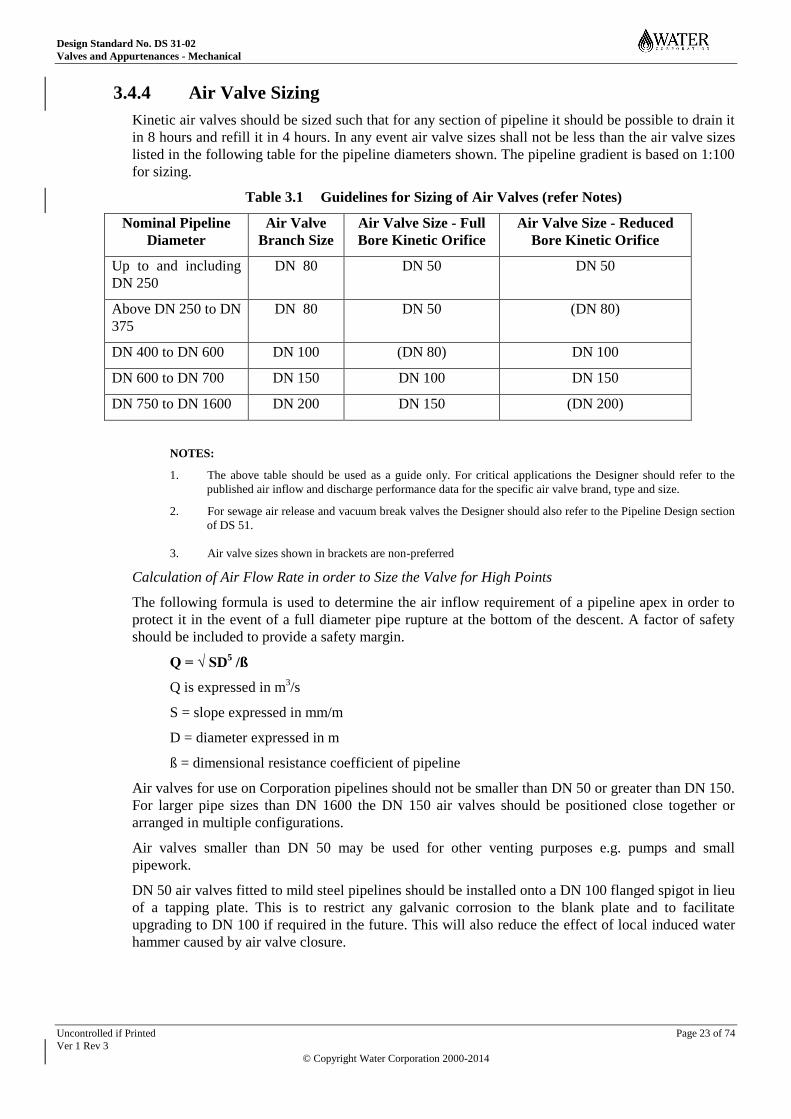
3.4.4 Air Valve Sizing
Kinetic air valves should be sized such that for any section of pipeline it should be possible to drain it
in 8 hours and refill it in 4 hours. In any event air valve sizes shall not be less than the air valve sizes
listed in the following table for the pipeline diameters shown. The pipeline gradient is based on 1:100
for sizing.
Table 3.1 Guidelines for Sizing of Air Valves (refer Notes)
Nominal Pipeline
Diameter
Air Valve
Branch Size
Air Valve Size - Full
Bore Kinetic Orifice
Air Valve Size - Reduced
Bore Kinetic Orifice
Up to and including
DN 250
DN 80 DN 50 DN 50
Above DN 250 to DN
375
DN 80 DN 50 (DN 80)
DN 400 to DN 600 DN 100 (DN 80) DN 100
DN 600 to DN 700 DN 150 DN 100 DN 150
DN 750 to DN 1600 DN 200 DN 150 (DN 200)
NOTES:
1. The above table should be used as a guide only. For critical applications the Designer should refer to the
published air inflow and discharge performance data for the specific air valve brand, type and size.
2. For sewage air release and vacuum break valves the Designer should also refer to the Pipeline Design section
of DS 51.
3. Air valve sizes shown in brackets are non-preferred
Calculation of Air Flow Rate in order to Size the Valve for High Points
The following formula is used to determine the air inflow requirement of a pipeline apex in order to
protect it in the event of a full diameter pipe rupture at the bottom of the descent. A factor of safety
should be included to provide a safety margin.
Q = √ SD5 /ß
Q is expressed in m3/s
S = slope expressed in mm/m
D = diameter expressed in m
ß = dimensional resistance coefficient of pipeline
Air valves for use on Corporation pipelines should not be smaller than DN 50 or greater than DN 150.
For larger pipe sizes than DN 1600 the DN 150 air valves should be positioned close together or
arranged in multiple configurations.
Air valves smaller than DN 50 may be used for other venting purposes e.g. pumps and small
pipework.
DN 50 air valves fitted to mild steel pipelines should be installed onto a DN 100 flanged spigot in lieu
of a tapping plate. This is to restrict any galvanic corrosion to the blank plate and to facilitate
upgrading to DN 100 if required in the future. This will also reduce the effect of local induced water
hammer caused by air valve closure.
Design Standard No. DS 31-02
Valves and Appurtenances - Mechanical
Uncontrolled if Printed Page 24 of 74
Ver 1 Rev 3
© Copyright Water Corporation 2000-2014
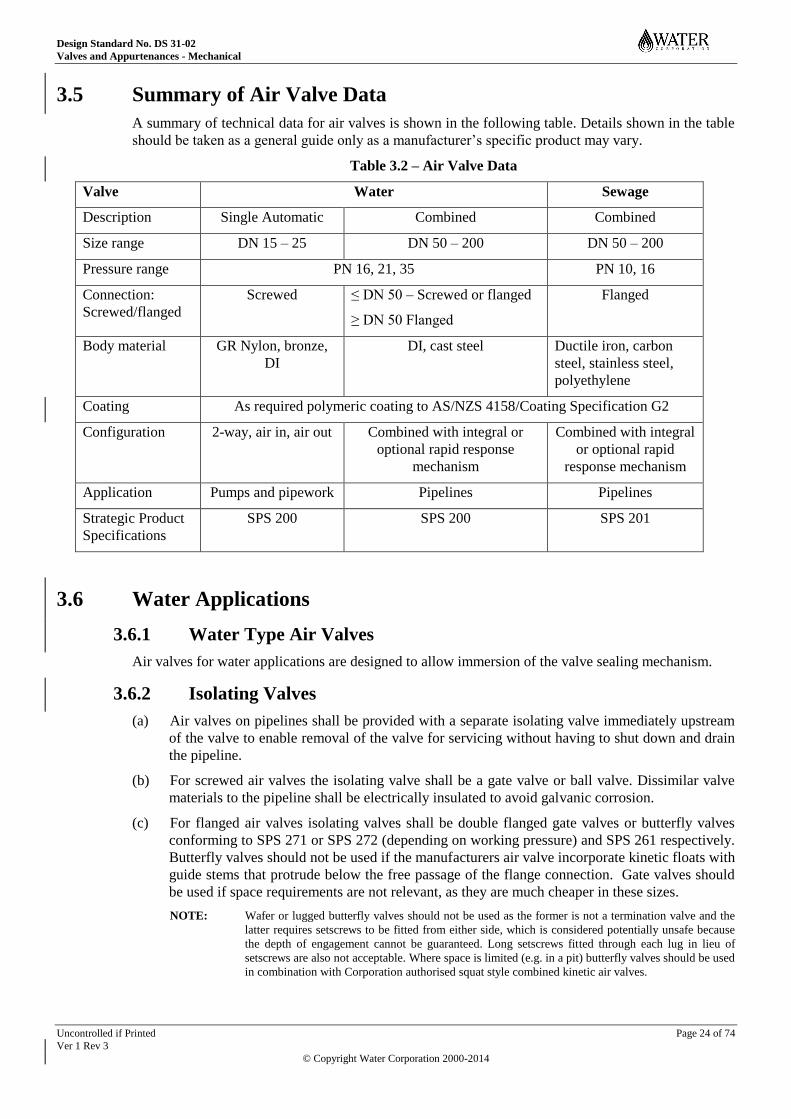
3.5 Summary of Air Valve Data
A summary of technical data for air valves is shown in the following table. Details shown in the table
should be taken as a general guide only as a manufacturer’s specific product may vary.
Table 3.2 – Air Valve Data
Valve Water Sewage
Description Single Automatic Combined Combined
Size range DN 15 – 25 DN 50 – 200 DN 50 – 200
Pressure range PN 16, 21, 35 PN 10, 16
Connection:
Screwed/flanged
Screwed ≤ DN 50 – Screwed or flanged
≥ DN 50 Flanged
Flanged
Body material GR Nylon, bronze,
DI
DI, cast steel Ductile iron, carbon
steel, stainless steel,
polyethylene
Coating As required polymeric coating to AS/NZS 4158/Coating Specification G2
Configuration 2-way, air in, air out Combined with integral or
optional rapid response
mechanism
Combined with integral
or optional rapid
response mechanism
Application Pumps and pipework Pipelines Pipelines
Strategic Product
Specifications
SPS 200 SPS 200 SPS 201
3.6 Water Applications
3.6.1 Water Type Air Valves
Air valves for water applications are designed to allow immersion of the valve sealing mechanism.
3.6.2 Isolating Valves
(a) Air valves on pipelines shall be provided with a separate isolating valve immediately upstream
of the valve to enable removal of the valve for servicing without having to shut down and drain
the pipeline.
(b) For screwed air valves the isolating valve shall be a gate valve or ball valve. Dissimilar valve
materials to the pipeline shall be electrically insulated to avoid galvanic corrosion.
(c) For flanged air valves isolating valves shall be double flanged gate valves or butterfly valves
conforming to SPS 271 or SPS 272 (depending on working pressure) and SPS 261 respectively.
Butterfly valves should not be used if the manufacturers air valve incorporate kinetic floats with
guide stems that protrude below the free passage of the flange connection. Gate valves should
be used if space requirements are not relevant, as they are much cheaper in these sizes.
NOTE: Wafer or lugged butterfly valves should not be used as the former is not a termination valve and the
latter requires setscrews to be fitted from either side, which is considered potentially unsafe because
the depth of engagement cannot be guaranteed. Long setscrews fitted through each lug in lieu of
setscrews are also not acceptable. Where space is limited (e.g. in a pit) butterfly valves should be used
in combination with Corporation authorised squat style combined kinetic air valves.
Design Standard No. DS 31-02
Valves and Appurtenances - Mechanical
Uncontrolled if Printed Page 25 of 74
Ver 1 Rev 3
© Copyright Water Corporation 2000-2014
3.7 Sewage Applications
3.7.1 Sewage Air Valves
Purpose designed sewage air valves should be used in sewage and dirty water applications. Sewage
air valves are designed to provide separation of the fluid from the orifice sealing mechanism to
minimise fouling. It is important that sewage air valves selected be designed so that they maintain the
air gap for a sustained period after priming of the pipeline. The inherent separation height of sewage
air valves means that the valves are relatively tall and for pit type service and therefore consideration
of the overall valve height should be taken into account with respect to pipeline depth. The design of
the sewage air valve should incorporate a manual ball valve located at the lower portion of the valve
body to enable pressure release, back washing and testing of the valve operation. An anti-slam
function should be available as an option.
3.7.2 Water Type Air Valves in Sewage Applications
Water type air valves should not normally be used in sewage or dirty water applications without the
approval of the Corporation. Use of water type air valves in sewage applications could produce
fouling of the sealing mechanism and valve malfunction resulting in leakage. Small water air release
valves have been used on sewage pressure mains up to size DN 250 where manual air bleed is not
considered practicable and risk associated with malfunction is low.
3.7.3 Manual Release and Air Valves
For information relating to provision of manual release points and air valves for sewage pressure
mains refer to the Pipeline Design Section of DS 51.
3.7.4 Air Valve Isolating Valves
Sewage air valves shall be provided with a separate isolating valve immediately upstream of the valve
to enable removal of the valve for servicing without having to shut down and drain the pipeline.
For screwed air valves the isolating valve should be a gate valve or ball valve. Dissimilar valve
materials to the pipeline shall be electrically insulated to avoid galvanic corrosion. For flanged air
valves isolating valves should be double flanged gate valves conforming to SPS 271 or SPS 272
depending on pressure rating. Butterfly valves shall not be used as they could be subject to fouling of
the disc.
3.8 Location of Air Valves
3.8.1 Air Valve Pits
Air valve pits should not be located in roadways or where they will be subject to flooding by
groundwater or surface water.
Air valves in buried pipelines in urban areas should be installed in pits.
Where it is necessary for air valve pits to have covers it is essential that ventilation be provided that
will handle the entry and exit air volumes required by the air valve. The venting should have a free
orifice which is twice that of the kinetic orifice in the air valve to ensure correct performance.
3.8.2 Above Ground Air Valves
In rural areas, air valves required for buried pipelines may be mounted above ground on a branch pipe
providing the obstruction poses no risk to others or is at no risk in terms of damage to the valve.
Above ground air valves should be of metal construction, and protected from potential damage e.g.
via steel bollards when fitted to buried pipelines. Air valves shall be installed in accordance with the
Drawing Series: EG20-5.
Design Standard No. DS 31-02
Valves and Appurtenances - Mechanical
Uncontrolled if Printed Page 26 of 74
Ver 1 Rev 3
© Copyright Water Corporation 2000-2014
4 BACKFLOW PREVENTION DEVICES
4.1 General
The design shall comply with the requirements of AS 3500 for the protection of drinking water from
backflow through a cross connection to the drinking supply.
Designers shall consider the following factors when designing backflow prevention requirements:
(a) Hazard rating of the facility or process e.g. high, medium or low
(b) Types of protection required e.g. individual, zone or containment
(c) Types of backflow risks involved e.g. back-siphonage or back pressure or both
(d) The future potential for cross connections to be made within a facility e.g. due to the number
and complexity of process pipes or as described above
(e) The type of backflow prevention device (or devices) required to address the above factors
4.2 Cross Connection
Backflow may result from an intentional or inadvertent cross connection or may be assessed as having
the potential to occur. For example a high hazard process tank may incorporate a correct air gap at the
water supply outlet but it has the potential for an operator to unwittingly attach a hose in order to
reduce splashing, which may trail into the process fluid negating the air gap. Accordingly a low
pressure in the water supply main could cause backflow of the process fluid into the drinking supply.
(These types of cross connections have been detected by Corporation inspectors).
Refer to DS 30-01 Glossary for further specific information on backflow definitions and terminology.
4.3 Hazard Ratings
In accordance with AS 3500 the following hazard ratings apply and these shall be used in order to
identify the type of backflow prevention device required for a particular application:
4.3.1 High Hazard
Any condition, device or practice within the water supply system and its operation that has the
potential to cause death.
4.3.2 Medium Hazard
Any condition, device or practice within the water supply system and its operation, which could
endanger health.
4.3.3 Low Hazard
Is any condition, device or practice within the water supply system and its operation, which would
constitute a nuisance but not endanger health.
4.4 Levels of Backflow Protection
There are three levels of protection that a Designer should consider when designing water supply
systems in a facility or plant and they are outlined in the following.
Design Standard No. DS 31-02
Valves and Appurtenances - Mechanical
Uncontrolled if Printed Page 27 of 74
Ver 1 Rev 3
© Copyright Water Corporation 2000-2014
4.4.1 Individual
Is the provision of a backflow prevention device at an individual fixture in order to protect the water
supply system upstream of the device from contamination e.g. a hose connection vacuum breaker
fitted at a tap.
Service water downstream of a backflow prevention device that provides individual protection shall
be deemed non potable. Accordingly all potable water fixtures shall be supplied from upstream of the
back flow prevention device.
4.4.2 Zone
Is the provision of a backflow prevention device at a section or zone in order to protect the water
supply system upstream of the device from contamination e.g. a reduced pressure zone device fitted
where the drinking supply enters a high hazard building or high hazard section of plant.
Service water downstream of a backflow prevention device that provides zone protection shall be
deemed non potable. Accordingly all potable water fixtures shall be supplied from upstream of the
back flow prevention device.
4.4.3 Containment
Is the provision of a backflow prevention device at a property boundary in order to protect the
Corporation’s water supply system upstream of the device from contamination e.g. a double
checkvalve device fitted at the property boundary for an industrial process identified as having a
medium hazard.
Service water downstream of a backflow prevention device that provides containment protection shall
be deemed potable up to the zone or if there is no zone device then the individual backflow prevention
device.
4.5 Backflow Prevention Devices
4.5.1 General
There are four basic devices that may be used for backflow prevention as follows:
(a) Air gaps or break tanks which are non mechanical devices used for high hazard protection
(b) Reduced pressure zone devices (RPZD)
(c) Vacuum breakers of the atmospheric and pressure types
(d) Double check valve assemblies (DCV)
4.5.2 Standards
Mechanical backflow prevention devices selected shall conform to the requirements of AS/NZS
2845.1.
Air gaps or break tanks shall conform to the requirements of AS 2845.2.
The devices for high and medium hazards are testable in accordance with AS/NZS 2845.1 and shall
be tested during commissioning, and field tested and maintained thereafter in accordance with the
requirements of AS 2845.3.
4.5.3 Field Testing and Maintainability
DCVs and RPZDs shall be maintainable in the field without removal from the line.
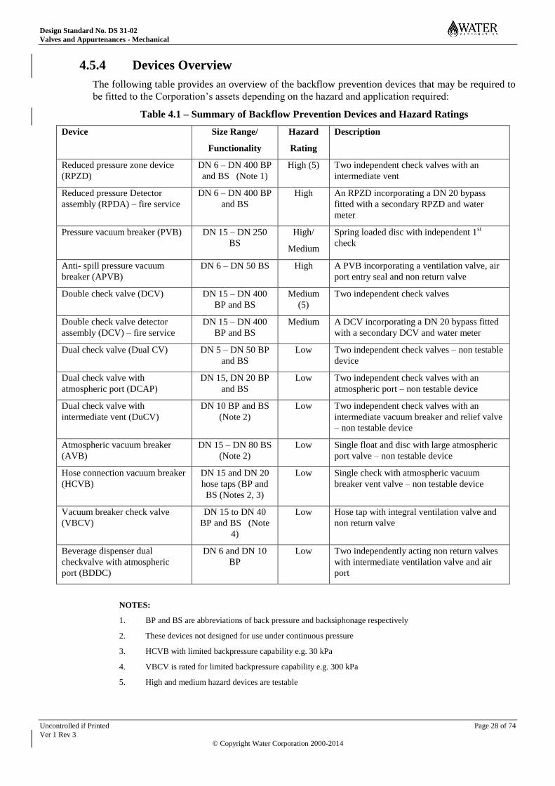
Design Standard No. DS 31-02
Valves and Appurtenances - Mechanical
Uncontrolled if Printed Page 28 of 74
Ver 1 Rev 3
© Copyright Water Corporation 2000-2014
4.5.4 Devices Overview
The following table provides an overview of the backflow prevention devices that may be required to
be fitted to the Corporation’s assets depending on the hazard and application required:
Table 4.1 – Summary of Backflow Prevention Devices and Hazard Ratings
Device Size Range/
Functionality
Hazard
Rating
Description
Reduced pressure zone device
(RPZD)
DN 6 – DN 400 BP
and BS (Note 1)
High (5) Two independent check valves with an
intermediate vent
Reduced pressure Detector
assembly (RPDA) – fire service
DN 6 – DN 400 BP
and BS
High An RPZD incorporating a DN 20 bypass
fitted with a secondary RPZD and water
meter
Pressure vacuum breaker (PVB) DN 15 – DN 250
BS
High/
Medium
Spring loaded disc with independent 1st
check
Anti- spill pressure vacuum
breaker (APVB)
DN 6 – DN 50 BS High A PVB incorporating a ventilation valve, air
port entry seal and non return valve
Double check valve (DCV) DN 15 – DN 400
BP and BS
Medium
(5)
Two independent check valves
Double check valve detector
assembly (DCV) – fire service
DN 15 – DN 400
BP and BS
Medium A DCV incorporating a DN 20 bypass fitted
with a secondary DCV and water meter
Dual check valve (Dual CV) DN 5 – DN 50 BP
and BS
Low Two independent check valves – non testable
device
Dual check valve with
atmospheric port (DCAP)
DN 15, DN 20 BP
and BS
Low Two independent check valves with an
atmospheric port – non testable device
Dual check valve with
intermediate vent (DuCV)
DN 10 BP and BS
(Note 2)
Low Two independent check valves with an
intermediate vacuum breaker and relief valve
– non testable device
Atmospheric vacuum breaker
(AVB)
DN 15 – DN 80 BS
(Note 2)
Low Single float and disc with large atmospheric
port valve – non testable device
Hose connection vacuum breaker
(HCVB)
DN 15 and DN 20
hose taps (BP and
BS (Notes 2, 3)
Low Single check with atmospheric vacuum
breaker vent valve – non testable device
Vacuum breaker check valve
(VBCV)
DN 15 to DN 40
BP and BS (Note
4)
Low Hose tap with integral ventilation valve and
non return valve
Beverage dispenser dual
checkvalve with atmospheric
port (BDDC)
DN 6 and DN 10
BP
Low Two independently acting non return valves
with intermediate ventilation valve and air
port
NOTES:
1. BP and BS are abbreviations of back pressure and backsiphonage respectively
2. These devices not designed for use under continuous pressure
3. HCVB with limited backpressure capability e.g. 30 kPa
4. VBCV is rated for limited backpressure capability e.g. 300 kPa
5. High and medium hazard devices are testable
Design Standard No. DS 31-02
Valves and Appurtenances - Mechanical
Uncontrolled if Printed Page 29 of 74
Ver 1 Rev 3
© Copyright Water Corporation 2000-2014
5 FLOW REGULATING VALVES
5.1 General
Valves used for flow, pressure or level control shall be selected based upon the minimum, normal and
maximum flow rates and any other relevant condition. Control valve types shall be selected so that the
process variables being controlled are controlled accurately over the full range of flow rates and
conditions. Control valve logic shall be in accordance with Drawing FQ-11 Valve Control contained
in DS 40-7.
Globe and vee-ball control valves should be sized so that the valve opening is between 5% and 90%
for equal percentage trim, or for linear trim selection, the valve opening should be between 10% and
80%.
Butterfly, diaphragm and pinch control valves shall be sized based on valve openings of 15% to 70%.
5.2 Valve Pits and Chambers
Where feasible control valves shall be installed above ground e.g. below ground valve pits and
chambers shall be avoided.
Where a below ground pit or chamber is unavoidable it shall comply with the requirements contained
in the general Pits and Chambers section of DS 30-02 and the specific Valve Pits and Chambers
section of this Standard.
5.3 Automatic Control Valves
In the context of this standard an automatic control valve refers to a control valve with a cast ductile
iron globe style body and cover chamber incorporating a diaphragm, spring and disc assembly. The
cover chamber incorporates ports that can be configured and with valving or pilot controls to provide
modulating and non-modulating operation. The configuration of pilot controls determines modulating
and non- modulating valve functionality e.g. on-off, pressure reducing, pressure sustaining etc. whilst
the pilot settings determines operating control parameters.
5.4 Pressure Reducing Valves
5.4.1 General
A pressure-reducing valve (PRV) automatically reduces a higher inlet pressure to a steady preset
lower downstream pressure regardless of changing flow rate and/or inlet pressure fluctuations. The
automatic control valve style PRV, which is hydraulic pilot operated is accurate and provides
repeatable and predictive pilot settings.
The PRV is configured with an adjustable pressure reducing control valve, which causes the main
valve to hold a steady outlet pressure. Should the downstream pressure exceed the preset pressure, the
main valve and pilot control valve will close drip tight.
5.4.2 Design Requirements
Designers should ensure the turn down does not exceed the manufacturer's recommendations where
large flow variations will be present. Large flow variations should be handled by incorporating
parallel pressure reducing valves of different sizes with the large valve handling the peak flows and
the small valve the low flows.
The valve supplier using a sizing program generally does selection of the appropriate valve.
Accordingly the Designer should provide the following information for valve sizing to be undertaken:
(a) Pipeline upstream and downstream pressures

Design Standard No. DS 31-02
Valves and Appurtenances - Mechanical
Uncontrolled if Printed Page 30 of 74
Ver 1 Rev 3
© Copyright Water Corporation 2000-2014
(b) Maximum and minimum flow rates required in the system.
The valve selection generally requires a valve of one size smaller than the pipeline nominal diameter.
Generally these control valves are not sensitive to turbulence so providing straight pipe lengths
upstream and downstream is not critical for valve performance.
Valves in series may be required for large pressure drop requirements. This is in order that the
pressure drop is staged to keep each valve within the manufacturers recommendations to avoid
cavitation. An upstream orifice plate may be an alternative to assist with high-pressure reduction.
Valves shall be fitted with a position indicator as a standard requirement.
5.4.3 Pipework Layout and Ancillaries
Pressure reducing valve installations should incorporate upstream and downstream isolating valves to
allow the valves to be removed for servicing. The downstream isolating valves should be located
sufficiently far downstream so that turbulent flow will not cause damage. The recommended
minimum distance is 5 - 7 pipe diameters. This is particularly important for butterfly valves, which
could be subject to disc flutter and eventual disc retaining pin failure and are accordingly not
recommended for this service. A gate valve would be less susceptible to turbulence than a butterfly
valve and is preferred where turbulence is likely to be a factor.
Pressure gauge tapping points should be provided upstream and downstream of the pressure-reducing
valve to facilitate setting of the pilot controls.
5.5 Pressure Sustaining Valves
5.5.1 General
A pressure-sustaining valve (PSV) automatically holds a steady preset inlet pressure within close
limits. The automatic control valve style PSV, which is pilot operated is accurate and provides
repeatable and predictive pilot settings.
The PSV is configured with an adjustable pressure control valve, which causes the main valve to hold
a steady inlet pressure. The pilot control system has fast opening characteristics to maintain a steady
pipeline pressure and slow closing characteristics to minimise surges.
5.5.2 Design Requirements
The valve supplier using a sizing program generally does selection of the appropriate valve.
Accordingly the Designer should provide the following information for valve sizing to be undertaken:
(a) Pipeline upstream and downstream pressures (downstream pressure is particularly important for
pressure sustaining valves to ensure cavitation does not present as a problem due to lack of
backpressure).
(b) Maximum and minimum flow rates in the system.
The valve selection generally requires a valve of one size smaller than the pipeline nominal diameter.
Generally these control valves are not sensitive to turbulence so providing straight pipe lengths
upstream and downstream is not critical for valve performance.
Valves shall be fitted with a position indicator as a standard requirement.
5.5.3 Pipework Layout and Ancillaries
PSV installations should incorporate upstream and downstream isolating valves to allow the valves to
be removed for servicing. The downstream isolating valves should be located sufficiently far
downstream so that turbulent flow will not cause damage. The recommended minimum distance is 5 -
7 pipe diameters. As mentioned previously this is particularly important for butterfly valves that could
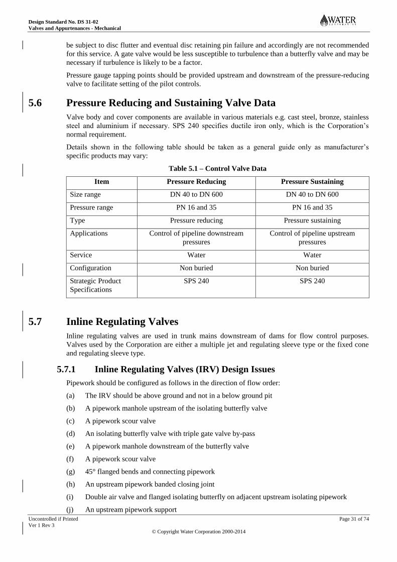
Design Standard No. DS 31-02
Valves and Appurtenances - Mechanical
Uncontrolled if Printed Page 31 of 74
Ver 1 Rev 3
© Copyright Water Corporation 2000-2014
be subject to disc flutter and eventual disc retaining pin failure and accordingly are not recommended
for this service. A gate valve would be less susceptible to turbulence than a butterfly valve and may be
necessary if turbulence is likely to be a factor.
Pressure gauge tapping points should be provided upstream and downstream of the pressure-reducing
valve to facilitate setting of the pilot controls.
5.6 Pressure Reducing and Sustaining Valve Data
Valve body and cover components are available in various materials e.g. cast steel, bronze, stainless
steel and aluminium if necessary. SPS 240 specifies ductile iron only, which is the Corporation’s
normal requirement.
Details shown in the following table should be taken as a general guide only as manufacturer’s
specific products may vary:
Table 5.1 – Control Valve Data
Item Pressure Reducing Pressure Sustaining
Size range DN 40 to DN 600 DN 40 to DN 600
Pressure range PN 16 and 35 PN 16 and 35
Type Pressure reducing Pressure sustaining
Applications Control of pipeline downstream
pressures
Control of pipeline upstream
pressures
Service Water Water
Configuration Non buried Non buried
Strategic Product
Specifications
SPS 240 SPS 240
5.7 Inline Regulating Valves
Inline regulating valves are used in trunk mains downstream of dams for flow control purposes.
Valves used by the Corporation are either a multiple jet and regulating sleeve type or the fixed cone
and regulating sleeve type.
5.7.1 Inline Regulating Valves (IRV) Design Issues
Pipework should be configured as follows in the direction of flow order:
(a) The IRV should be above ground and not in a below ground pit
(b) A pipework manhole upstream of the isolating butterfly valve
(c) A pipework scour valve
(d) An isolating butterfly valve with triple gate valve by-pass
(e) A pipework manhole downstream of the butterfly valve
(f) A pipework scour valve
(g) 45° flanged bends and connecting pipework
(h) An upstream pipework banded closing joint
(i) Double air valve and flanged isolating butterfly on adjacent upstream isolating pipework
(j) An upstream pipework support
Design Standard No. DS 31-02
Valves and Appurtenances - Mechanical
Uncontrolled if Printed Page 32 of 74
Ver 1 Rev 3
© Copyright Water Corporation 2000-2014
(k) An upstream pipework restrained dismantling joint adjacent to the IRV
(l) The IRV.
(m) A downstream reducer incorporating a manhole on the side with access steps
(n) Support of the downstream reducer at each flange (flanges act as stiffeners in lieu of flexible
pipe body)
(o) 45° flanged bends downstream of the reducer
(p) Downstream closing joint
(q) Thrust blocks upstream and downstream
(r) Sound attenuation building with removable roof in noise sensitive areas
NOTES:
1. Care is required to ensure that the valve connections are not subjected to lateral forces or couples. The tie-
bolt design of the fixed cone style of IRV produces flexibility in the valve, which can cause misalignment
when subjected to external forces particularly for large valves e.g. DN 1200
2. Valves should be installed into position then pipework attached at both ends with closure of the pipework via
banded joints to ensure alignment without applying unnecessary forces. Pipework should be supported so
loads are not transferred to the valve inlet and outlet flanges.
5.8 Discharge Regulating Valve
Discharge regulating valves are either the horizontal or vertical are used as scour valves or water
release valves to regulate flow and dissipate the energy due to the potential head in a dam or pipeline.
The Corporation uses cone dispersal valves mainly for this purpose. However for small dams where
low cost infrequently operated scour valves are proposed a plug valve may be suitable. Cone dispersal
valves currently used by the Corporation are generally of the fixed cone sliding regulating sleeve
style. Valves may be manual or electrically operated.
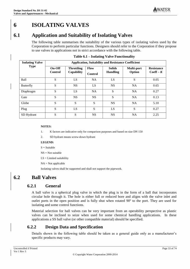
Design Standard No. DS 31-02
Valves and Appurtenances - Mechanical
Uncontrolled if Printed Page 33 of 74
Ver 1 Rev 3
© Copyright Water Corporation 2000-2014
6 ISOLATING VALVES
6.1 Application and Suitability of Isolating Valves
The following table summarises the suitability of the various types of isolating valves used by the
Corporation to perform particular functions. Designers should refer to the Corporation if they propose
to use valves in applications not in strict accordance with the following table.
Table 6.1 – Isolating Valve Functionality
Isolating Valve
Type
Application, Suitability and Resistance Coefficient
On-Off
Control
Throttling
Capability
Flow
Control
Solids
Handling
Multi-port
Option
Resistance
Coeff – K
Ball S LS NA LS S 0.05
Butterfly S NS LS NS NA 0.65
Diaphragm S LS NA S NA 0.27
Gate S NS NS S NA 0.13
Globe S S S NS NA 5.10
Plug S LS S LS S 0.27
SD Hydrant S S NS NS NA 2.25
NOTES:
1. K factors are indicative only for comparison purposes and based on size DN 150
2. SD hydrant means screw-down hydrant
LEGEND:
S = Suitable
NS = Not suitable
LS = Limited suitability
NA = Not applicable
Isolating valves shall be supported and shall not support the pipework.
6.2 Ball Valves
6.2.1 General
A ball valve is a spherical plug valve in which the plug is in the form of a ball that incorporates
circular hole through it. The hole is either full or reduced bore and aligns with the valve inlet and
outlet ports in the open position and is fully shut when rotated 90º to the port. They are used for
isolating and some control functions.
Material selection for ball valves can be very important from an operability perspective as plastic
valves can be inclined to seize when used for some chemical handling applications. In these
applications a SS ball valve (or other compatible material) should be specified.
6.2.2 Design Data and Specification
Details shown in the following table should be taken as a general guide only as a manufacturer’s
specific products may vary.
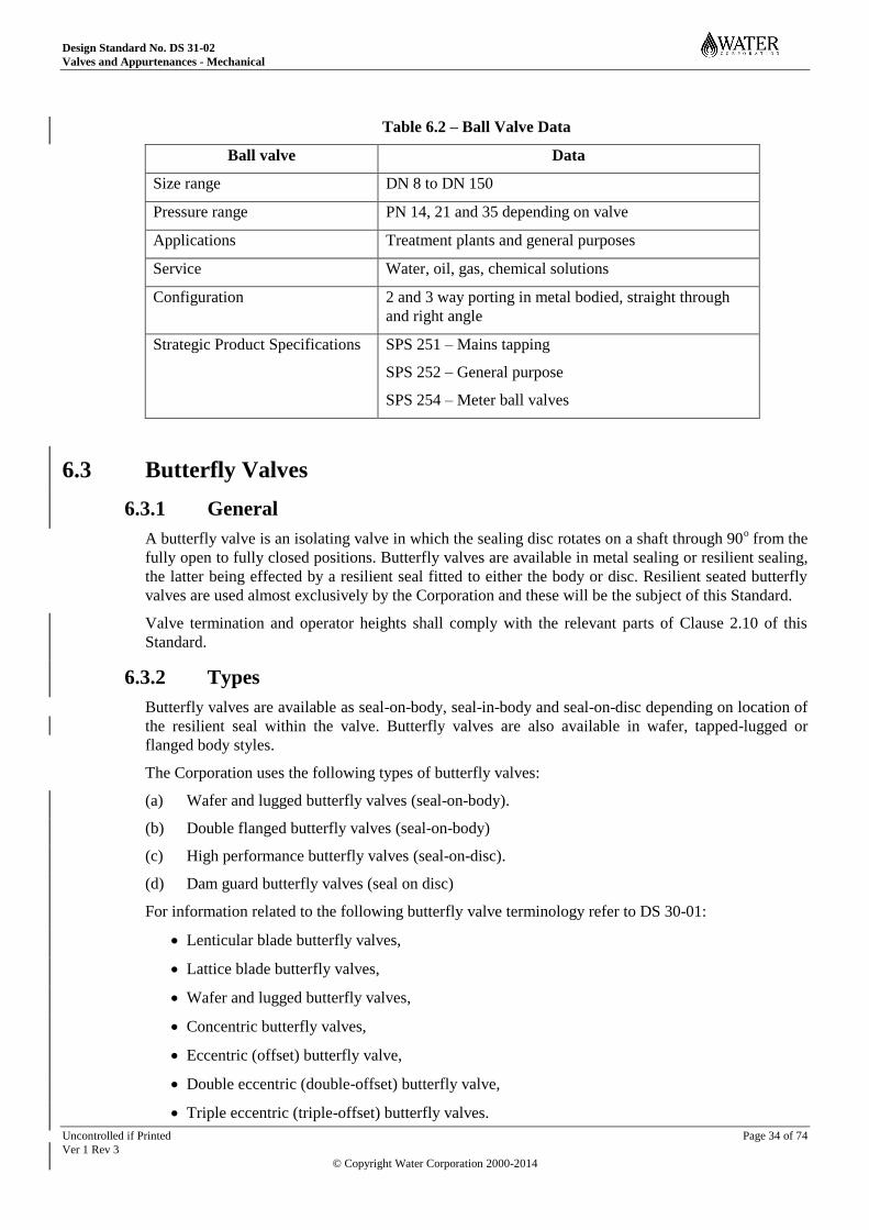
Design Standard No. DS 31-02
Valves and Appurtenances - Mechanical
Uncontrolled if Printed Page 34 of 74
Ver 1 Rev 3
© Copyright Water Corporation 2000-2014
Table 6.2 – Ball Valve Data
Ball valve Data
Size range DN 8 to DN 150
Pressure range PN 14, 21 and 35 depending on valve
Applications Treatment plants and general purposes
Service Water, oil, gas, chemical solutions
Configuration 2 and 3 way porting in metal bodied, straight through
and right angle
Strategic Product Specifications SPS 251 – Mains tapping
SPS 252 – General purpose
SPS 254 – Meter ball valves
6.3 Butterfly Valves
6.3.1 General
A butterfly valve is an isolating valve in which the sealing disc rotates on a shaft through 90o from the
fully open to fully closed positions. Butterfly valves are available in metal sealing or resilient sealing,
the latter being effected by a resilient seal fitted to either the body or disc. Resilient seated butterfly
valves are used almost exclusively by the Corporation and these will be the subject of this Standard.
Valve termination and operator heights shall comply with the relevant parts of Clause 2.10 of this
Standard.
6.3.2 Types
Butterfly valves are available as seal-on-body, seal-in-body and seal-on-disc depending on location of
the resilient seal within the valve. Butterfly valves are also available in wafer, tapped-lugged or
flanged body styles.
The Corporation uses the following types of butterfly valves:
(a) Wafer and lugged butterfly valves (seal-on-body).
(b) Double flanged butterfly valves (seal-on-body)
(c) High performance butterfly valves (seal-on-disc).
(d) Dam guard butterfly valves (seal on disc)
For information related to the following butterfly valve terminology refer to DS 30-01:
Lenticular blade butterfly valves,
Lattice blade butterfly valves,
Wafer and lugged butterfly valves,
Concentric butterfly valves,
Eccentric (offset) butterfly valve,
Double eccentric (double-offset) butterfly valve,
Triple eccentric (triple-offset) butterfly valves.
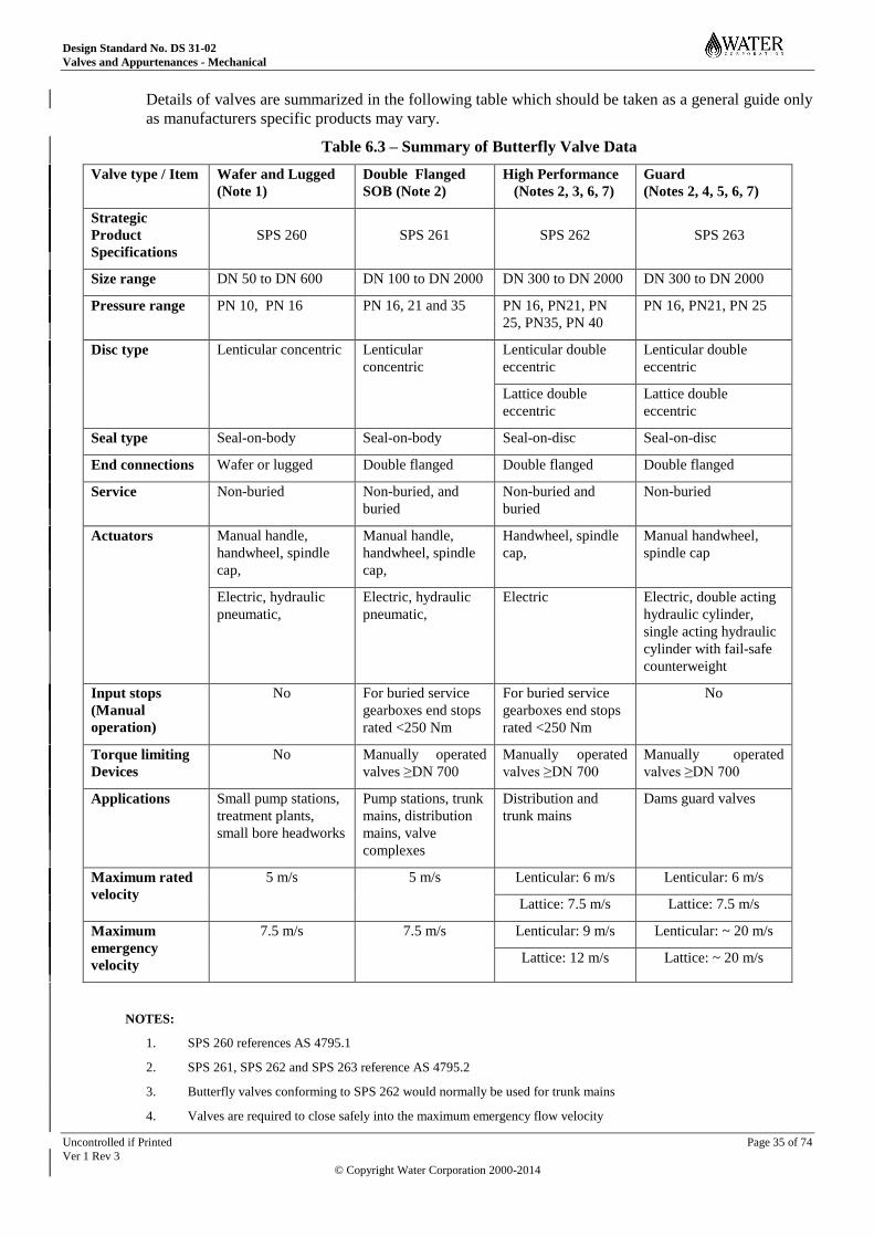
Design Standard No. DS 31-02
Valves and Appurtenances - Mechanical
Uncontrolled if Printed Page 35 of 74
Ver 1 Rev 3
© Copyright Water Corporation 2000-2014
Details of valves are summarized in the following table which should be taken as a general guide only
as manufacturers specific products may vary.
Table 6.3 – Summary of Butterfly Valve Data
Valve type / Item Wafer and Lugged
(Note 1)
Double Flanged
SOB (Note 2)
High Performance
(Notes 2, 3, 6, 7)
Guard
(Notes 2, 4, 5, 6, 7)
Strategic
Product
Specifications
SPS 260
SPS 261
SPS 262
SPS 263
Size range DN 50 to DN 600 DN 100 to DN 2000 DN 300 to DN 2000 DN 300 to DN 2000
Pressure range PN 10, PN 16 PN 16, 21 and 35 PN 16, PN21, PN
25, PN35, PN 40
PN 16, PN21, PN 25
Disc type Lenticular concentric Lenticular
concentric
Lenticular double
eccentric
Lenticular double
eccentric
Lattice double
eccentric
Lattice double
eccentric
Seal type Seal-on-body Seal-on-body Seal-on-disc Seal-on-disc
End connections Wafer or lugged Double flanged Double flanged Double flanged
Service Non-buried Non-buried, and
buried
Non-buried and
buried
Non-buried
Actuators Manual handle,
handwheel, spindle
cap,
Manual handle,
handwheel, spindle
cap,
Handwheel, spindle
cap,
Manual handwheel,
spindle cap
Electric, hydraulic
pneumatic,
Electric, hydraulic
pneumatic,
Electric Electric, double acting
hydraulic cylinder,
single acting hydraulic
cylinder with fail-safe
counterweight
Input stops
(Manual
operation)
No For buried service
gearboxes end stops
rated <250 Nm
For buried service
gearboxes end stops
rated <250 Nm
No
Torque limiting
Devices
No Manually operated
valves ≥DN 700
Manually operated
valves ≥DN 700
Manually operated
valves ≥DN 700
Applications Small pump stations,
treatment plants,
small bore headworks
Pump stations, trunk
mains, distribution
mains, valve
complexes
Distribution and
trunk mains
Dams guard valves
Maximum rated
velocity
5 m/s 5 m/s Lenticular: 6 m/s Lenticular: 6 m/s
Lattice: 7.5 m/s Lattice: 7.5 m/s
Maximum
emergency
velocity
7.5 m/s 7.5 m/s Lenticular: 9 m/s Lenticular: ~ 20 m/s
Lattice: 12 m/s Lattice: ~ 20 m/s
NOTES:
1. SPS 260 references AS 4795.1
2. SPS 261, SPS 262 and SPS 263 reference AS 4795.2
3. Butterfly valves conforming to SPS 262 would normally be used for trunk mains
4. Valves are required to close safely into the maximum emergency flow velocity

Design Standard No. DS 31-02
Valves and Appurtenances - Mechanical
Uncontrolled if Printed Page 36 of 74
Ver 1 Rev 3
© Copyright Water Corporation 2000-2014
5. The hydro-dynamic torque for emergency velocity closure (e.g. 20 m/s) is relatively high. Accordingly the drive train
and valve shaft assembly must be rated to safely withstand closure into emergency flow velocity without structural
damage. Some damage of the seal may be expected after emergency flow closure which would be a rare event.
6. Double eccentric valves may be uni-directional or bi-directional. If bi-directional sealing is required it would need to
be specified.
7. The maximum rated and emergency velocities shown for high performance and guard valves are a guide only and the
valve manufacturer should be consulted for specific ratings where high velocity is anticipated.
6.3.3 Design Features
(a) Butterfly valves tend to be cheaper than gate valves for sizes above DN 500.
(b) Butterfly valves are externally smaller than gate valves which provides for simpler, cheaper and
more compact installations where appropriate. This particularly applies to double flanged seal-
on-body butterfly valves which are suitable for buried service requiring no costly pipework pits.
(c) Seal-on-body waterworks butterfly valves are essentially manufactured from corrosion resistant
waterway materials whereas traditionally waterworks gate valves and seal-on-disc butterfly
valves have been prone to failure by corrosion long term e.g. after 30 years.
(d) Butterfly valves may be suitable for some control applications e.g. between 20º and 60º disc
angle depending on the flow and pressure drop requirements.
(e) Resilient seated butterfly valves provide for drop tight sealing.
6.3.4 Butterfly Valve Design Constraints
(a) Butterfly valves should be used for on-off and limited control valve service. They shall not be
used for throttling service because of the likelihood of cavitation damage (refer Appendix A).
(b) Butterfly valves shall not be located close to other pipe appurtenances that can induce disturbed
streamlines likely to produce disc flutter and consequently premature wear or failure of
components e.g. bends or immediately downstream of a control valve or pump.
(c) To obviate disc flutter, a straight length of pipe of 3 - 5 pipe diameters shall be provided
upstream of the butterfly valve. Refer to Flow Regulating Valves Design Criteria relating to
pressure reducing valve pipework layout and ancillaries for further specific information.
(d) Butterfly valves shall not be used in raw sewage as they will be subject to fouling and
malfunction. Butterfly valves may be used for effluent or screened sewage providing it is clear
(no solid or fibrous material).
6.3.5 Wafer and Lugged Butterfly Valves
(a) Wafer and lugged butterfly valves are relatively cheap valves designed for above ground (non
buried) service and should only be used for medium duty isolation applications.
(b) General purpose butterfly valves are commonly available in sizes from DN 50 to DN 600 and
for pressures from PN 10 to PN 16. End connections are wafer style for fitting between an AS
4087 flange bolt circle, tapped lugged to AS 2129 Table E. Valves are of the seal-on-body type
with components in the wetted area being of non corrosive materials. The resilient seal-on-body
feature includes integral flange gaskets so that separate flange gaskets are not required.
(c) For manual operation, valves may be fitted with a lever and notch plate for sizes up to and
including DN 200 (refer Note). For valve sizes above DN 200 a gearbox should be fitted. In
addition to manual operation valves may be electrically, hydraulically or pneumatically
actuated. Wafer and Lugged butterfly valves shall not be used on pipework for major pump
stations. However they may be used for non-critical ancillary plant such as minor pump
stations, borefield headworks and treatment plant applications.
NOTE: A gearbox is recommended for DN 200 valves where PN >400kPa.
Design Standard No. DS 31-02
Valves and Appurtenances - Mechanical
Uncontrolled if Printed Page 37 of 74
Ver 1 Rev 3
© Copyright Water Corporation 2000-2014
(d) Wafer and lugged butterfly valves should only be used for pipe velocities up to 5 m/s or short
term (e.g. 30 minutes) emergency velocities to 7.5 m/s.
(e) Large wafer and lugged butterfly valves should generally not be opened against full differential
head such as would occur when opening a valve exposed to an upstream head and an empty
pipe downstream. Under these circumstances the head should be balanced before opening the
valve. This can be achieved by providing a bypass around the valve (refer to Bypass Valves in
this Standard). Under certain hydraulic conditions opening against full differential can be
tolerated subject to approval of the manufacturer.
(f) Wafer and lugged butterfly valves shall not be used as termination valves (refer Note for air
valves).
6.3.6 Double Flanged Seal-on-Body (SOB) Butterfly Valves
(a) Double flanged SOB butterfly valves are relatively expensive valves designed for above and
buried service for medium to heavy duty isolation and control applications.
(b) Double flanged SOB butterfly valves are available in sizes from DN 100 to DN 2000 and for
pressures from PN 10 to PN 35. End connections are double flanged or tapped ring style.
Valves are of the seal-on-body type with components in the wetted area being of non corrosive
materials. The SOB feature includes integral flange gaskets so that separate flange gaskets are
not required.
(c) For manual operation a gearbox should be fitted (refer Note below). In addition to manual
operation valves may be electrically, hydraulically or pneumatically actuated.
NOTE: Valves are normally fitted with a gearbox for manual operation. Valve sizes and pressure classes up
to DN 150 PN 21 could be fitted with a lever in lieu of a gearbox however the Corporation only uses
this arrangement for DN 150 PN 21 valves for fitting immediately under air valves to provide quick
on-off operation.
(d) Butterfly valves should be used for pump suction and delivery pipework in lieu of large gate
valves because they are more compact and cheaper in sizes above DN 500. This is providing the
extra head loss they incur over a gate valve does not impact adversely on the design e.g. head
loss on the suction side could be important for critical NPSHa situations.
(e) Double flanged SOB butterfly valves should only be used for pipe velocities to 5 m/s or short
term (e.g. 30 minutes) emergency velocities to 7.5 m/s.
(f) Double flanged SOB butterfly valves shall be installed with the shaft in the horizontal position
so that the lower half of the disc opens in the direction of the flow. Refer also DS 38-01 for
further information
(g) The gearbox orientation for double flanged SOB butterfly valves, where possible shall be
specified as being located on the left hand side of the valve when looking in the direction of the
flow. Refer also DS 38-01 for further information.
(h) Large double flanged SOB butterfly valves should generally not be opened against full
differential head such as would occur when opening a valve exposed to an upstream head and
an empty pipe downstream. Under these circumstances the head should be balanced before
opening the valve. This can be achieved by providing a bypass around the valve (refer to
Bypass Valves in this Standard). Under certain hydraulic conditions opening against full
differential can be tolerated subject to approval of the manufacturer.
(i) Double flanged SOB butterfly valves incorporate an enclosed gearbox and accordingly may be
installed in the following applications:
Non-buried;
Non-buried with extended spindle; or
Buried service with extended spindle.
Design Standard No. DS 31-02
Valves and Appurtenances - Mechanical
Uncontrolled if Printed Page 38 of 74
Ver 1 Rev 3
© Copyright Water Corporation 2000-2014
Extended spindle valves shall be fitted with a position indicator.
6.3.7 High Performance Butterfly Valves
(a) High performance butterfly valves are used for high velocity applications, such as would be
required for large distribution mains.
(b) High performance butterfly valves are seal-on-disc type. In order to minimise dissimilar metal
corrosion, valves shall incorporate an all-stainless steel disc, and disc seal ring and fasteners. A
ductile iron body is acceptable however all wetted surfaces and interfaces shall be fully and
effectively coated and the coating or a suitable sealant isolates the stainless steel body ring
fastener threads from moisture. Ingress of water into interfaces can promote growth of iron
tubercles which can interfere with and damage the disc seal. Similarly ingress of moisture into
the fastener thread area could likely produce graphitic corrosion causing dislodgement of the
body ring during valve operation.
(c) Seal-on-disc butterfly valves require separate flange gaskets.
6.3.8 Guard Valves
6.3.8.1 General
Butterfly guard valves are isolating valves, generally located immediately downstream of a dam wall.
Guard valves shall be designed to operate in either the fully open or fully closed positions and close
safely under the maximum emergency flow velocity in the event of catastrophic downstream
pipework failure. Guard valves are structurally more robust than standard butterfly valves and are
normally fitted with higher rated actuators (refer Note 1).
Guard valve actuators are available in standard or fail-safe types as follows:
• The standard guard valve can be actuated via a manual or an electric actuator, or an electro-
hydraulic double-acting cylinder (refer Note 2). The standard actuator can be closed manually
via the electric actuator handwheel or via a manual hand pump in the case of the electro-
hydraulic actuator in the event of a power failure.
• The fail-safe guard valve actuator comprises an electro-hydraulic power pack, and a single-
acting hydraulic cylinder and counterweight assembly. The valve actuator is configured to open
hydraulically and close under the action of the counterweight.
NOTES:
1. Whilst guard valves are designed to be structurally capable of closing into the maximum emergency flow velocity
some damage to the resilient seal may occur.
2. Rotary hydraulic actuators are not favoured due to higher cost and complexity.
6.3.8.2 Risk Potential
The key issue in considering the type of butterfly valve used as a guard valve depends upon the degree
of importance of the water body in the dam. Therefore it is necessary to determine the risk potential
and the consequence if the water body was lost or seriously depleted e.g. whether the risk is strategic
or non strategic.
NOTE: The decision as to the integrity of the valves required ultimately rests with the Dams and Dams Safety Section
and they should adjudicate on this (normally would be as a design or specification requirement).
6.3.8.3 Valve Types
If the guard valve is likely to be exposed to sustained flow velocities greater than 5.0 m/s then this is
generally outside the maximum performance capability of standard seal on body butterfly valves. In
this event there are two options available. One option is to utilise seal-on-body butterfly valves and
the others are the use of high performance seal-on-disc butterfly valve or a purpose designed guard
valve as further discussed.
Design Standard No. DS 31-02
Valves and Appurtenances - Mechanical
Uncontrolled if Printed Page 39 of 74
Ver 1 Rev 3
© Copyright Water Corporation 2000-2014
NOTE: Use of ring follower valves as guard valves was common decades ago but is probably not feasible now due to
their lack of availability, undoubtedly due to considerably cheaper and more compact butterfly valves.
6.3.8.4 Seal-On-Body Butterfly Valves
Use of seal-on-body butterfly valves are preferred over seal-on-disc butterfly valves for general
waterworks applications because of their simple construction, corrosion resistant characteristics and
lower cost. However seal-on-body butterfly valves are generally limited to 5 m/s continuous velocity
and not normally suitable for high emergency flow velocities because of damaging downstream
cavitation which can cause rubber failure whereby the rubber can tear away in chunks. However a
case for their use may be made under the following circumstance:
(a) For non critical and low risk applications it may be acceptable to use seal-on-body butterfly
valves in conjunction with an actuator designed to close against maximum differential head.
This would be in the full knowledge that the maximum performance capability of the valve may
be exceeded under emergency flow conditions and that liner failure could occur (perhaps
catastrophic).
(b) A valve actuator rated to close under maximum differential should theoretically be able to be
close the valve against emergency flow conditions. However this assumes that any seat damage
would not cause an obstruction which could act to prevent full closure. Hopefully any resulting
leakage through the damaged seat would be tolerable and sufficiently manageable to enable a
bulkhead gate to be fitted upstream in order to rectify the downstream failure. The valve would
then have to be removed for repair if there was damage to the liner.
NOTE: The use of seal-on-body butterfly valves would obviously not be a preferred option for protecting
strategic water bodies and should only be used where there was low risk of failure and minimal
strategic implications.
6.3.8.5 Seal-On-Disc Butterfly Valves
For critical applications guard valves should be of the high performance butterfly valve type rated for
closure against maximum differential head and suitable for continuous operation under emergency
flow conditions e.g. without seal failure. Guard valves would normally be seal-on-disc type butterfly
valves fitted with a lenticular or lattice blade and designed for continuous flow velocities up to 20
m/s. The seal-on-disc valve rubber seal fitted to the disc is not subject to damaging cavitation.
However seal-on-disc butterfly valves have been prone to premature failure in the past due to
corrosion of the disc and body fastener threads and other areas of the ductile iron or carbon steel valve
body exposed to immersion.
The Corporation has addressed corrosion of seal-on-disc butterfly valves over recent years by
requiring high performance butterfly valve and guard valve components subject to immersion be
manufactured in accordance with the following :
(a) Disc, disc and body seat rings and fasteners to be manufactured from corrosion resistant
material.
(b) Ductile iron body seat ring mating face and tapped holes to be sealed against moisture ingress.
(c) All immersed ductile iron or carbon steel surfaces and interfaces to be fully coated and sealed
respectively to eliminate contact with moisture.
6.3.9 Direction of Rotation for Closure
Butterfly valve operators (e.g. key or handwheel) shall rotate anti-clockwise for closure of the valve.
Design Standard No. DS 31-02
Valves and Appurtenances - Mechanical
Uncontrolled if Printed Page 40 of 74
Ver 1 Rev 3
© Copyright Water Corporation 2000-2014
6.4 Diaphragm Valves
6.4.1 General
The diaphragm valve is an isolating valve that utilises an actuator driven diaphragm to seal against the
valve body in either a weir or straight-through flow way body type. The diaphragm serves not only as
the sealing mechanism for the process fluid but also prevents fluid contact with the bonnet internal
components.
The weir type diaphragm valve produces less flexing of the diaphragm because of the shorter travel
required and also presents a seal face that requires a lower closing force than the straight-through flow
type.
The straight-through flow type has a clear flow way and this makes it more suitable for solids
handling however the longer travel of the diaphragm limits the availability of suitable diaphragm
elastomers.
6.4.2 Data and Specification
Details shown in the following table should be taken as a general guide only as a manufacturer’s
specific products may vary.
Table 6.4 – Diaphragm Valve Data
Item Straight Through Weir
Size range Screwed – DN 25 to DN 50
Flanged – DN 25 – DN 350
Screwed – DN 8 to DN 80
Flanged – DN 15 – DN 350
Pressure range 1000 kPa for DN 25 – DN 50
600 kPa for DN 65 – DN 150
300 kPa for DN 200 – DN 250
170 kPa for DN 300
1600 kPa for DN 8 – DN 50
1000 kPa for DN 65 – DN 150
800 kPa for DN 200
500 kPa, 400 kPa, 350 kPa for DN
250, DN 300 and DN 350 resp.
Type Straight-through Weir
Applications General purposes, WTP’s General purposes, treatment plants
Service Water, solids, corrosive and
abrasive fluids
Water, corrosive and abrasive fluids
Configuration Non buried Non buried
Strategic Product
Specifications
N/A N/A
6.5 Gate Valves for General Purposes
6.5.1 General
In the context of this Standard this section refers to a copper alloy or stainless steel isolating valve
with non rising stem that employs a guided metal wedge onto metal seats to effect a seal.
Design Standard No. DS 31-02
Valves and Appurtenances - Mechanical
Uncontrolled if Printed Page 41 of 74
Ver 1 Rev 3
© Copyright Water Corporation 2000-2014
6.5.2 Design Requirements
Gate valves should be used for general purposes for unrestricted fluid flow, lowest pressure drop, and
for infrequent operation. They are available in sizes from DN 15 to DN 100 in screwed or flanged end
connections.
Gate valves should not be used for modulating or throttling purposes. Velocity of flow through a
partially closed wedge is likely to cause vibration and chattering that can damage the sealing faces
and produce erosion of the wedge.
Gate valves should normally be used in conjunction with swing check non-return valves, not lift type
non-return valves, on low to medium pipeline velocities.
6.5.3 Data and Specification
Details shown in the following table should be taken as a general guide only as a manufacturer’s
specific products may vary.
Table 6.5 – Gate Valve Data
Item Copper Alloy Stainless Steel
Screwed Flanged
Size range DN 8 to DN 50 DN 10 to DN 100 DN 6 to DN 100
Pressure range PN 35 PN 21 2000 kPa
Type Screwed Flanged Screwed
Applications General purposes,
treatment plants
General purposes,
treatment plants
Treatment plants
Service Water, oil, gas Water, oil, gas Chemical solutions
Strategic
Product
Specifications
SPS 255 SPS 255 -
6.6 Gate Valves for Waterworks Purposes
6.6.1 General
In the context of this Standard the term gate valve refers to a ductile iron waterworks isolating valve
with non rising stem that employs either a guided resilient or metal gate onto the body or metal seats
respectively to effect a seal.
NOTE: The term gate valve has been adopted as the preferred terminology since the inclusion of ‘gate valves ’ into
AS 2638.2 in 2002. Formerly they were known as “sluice valves”.
Gate valves should not be used for modulating or throttling because of their inherent difficulty in
precisely regulating flow. This is due to their relatively high discharge capacity variation for relatively
small gate movement in the controllable range, which is approximately the last one third from the
closed position. Further, the velocity of flow through a partially closed gate is likely to cause
turbulence with associated gate vibration and chattering due to the relatively short gate guide length.
Chattering can damage the seating faces and the flow velocity can produce erosion.
Valve termination and operator heights shall comply with the relevant parts of Clause 2.10 of this
Standard.
Design Standard No. DS 31-02
Valves and Appurtenances - Mechanical
Uncontrolled if Printed Page 42 of 74
Ver 1 Rev 3
© Copyright Water Corporation 2000-2014
6.6.2 Valve Orientation
Ideally both metal and resilient seated gate valves should be installed in horizontal pipelines i.e. with
the stem vertical, particularly if grit and solids are present as is the case for sewage applications.
There is a risk of the bonnet area becoming clogged with solids for sewage applications if the stem is
not oriented vertically. This is not so critical for clean water.
Installation in horizontal pipelines is also an advantage in terms of inspection and servicing of large
valves where direct lift can be used. Lifting of the bonnet and internal components for large valves
could present difficulties for vertical pipelines. This is because of lifting constraints that would
otherwise present themselves in trying to remove heavy components horizontally. Further, large
valves installed with the stem horizontally may need specially designed body liners and wedge shoes.
6.6.3 Buried Gate Valves
Gate valves without gearboxes may be installed below ground e.g. reticulation valves. Below ground
valves shall be fitted extended spindles.
Large gate valves on pipelines may be partially buried to eliminate costly valve pits e.g. distribution
mains. Valves should not be buried above the body to bonnet lower flange. Exposed adjustable glands
shall not be buried and may need gland covers depending on the valve design. A platform, handrailing
and steps shall be provided where necessary to allow safe access to the valve operator.
6.6.4 Metal Seated Gate Valves
Metal seated gate valves used for water and sewage pump stations shall comply with SPS 271 for
sizes above DN 750 and for pressure classes above PN 25 unless authorized by the Corporation..
NOTE: Resilient seated gate valves are preferred over metal seated for sizes ≤DN 750 and for pressure classes ≤PN 25
Gate valves shall be fitted with a bypass in accordance with the Bypass Valves clause in this section if
they are likely to be subject to unbalanced head conditions.
Gate valves with gearboxes (generally above DN 500) are normally installed above ground (non
buried) in a valve pit. However subject to approval by the Corporation they may be partially buried in
order to save valve pit costs e.g. up to the body-to-bonnet flange for pipelines outside the pump
station. For gate valves in sizes larger than those authorised for resilient seated gate valves and for all
PN 35 valves, metal seated gate valves are required.
Metal seated gate valves:
(a) Incorporate a pocket to accept the wedge in the closed position, which can collect debris making
them difficult to close and therefore seal,
(b) Are not suitable for drop tight sealing, as they will always pass a small amount of fluid.
6.6.5 Resilient Seated Gate Valves
Resilient seated gate valves for water and sewage shall conform to the requirements of SPS 272 and
are suitable for use in sizes up to and including DN 750 and pressure classes to PN 25.
Resilient seated gate valves are generally preferred over metal seated gate valves because they offer a
number of advantages:
(a) The construction of the resilient seated valves allow a continuous coating to be applied to the
body, encapsulating the ductile cast iron and protecting it from corrosion. The gate is also fully
encapsulated with rubber and is therefore protected from corrosion. A metal seated gate valve
has gunmetal seating rings set into the ductile cast iron and in practice it may be difficult to
obtain a fully effective coating at this dissimilar metal interface.

Design Standard No. DS 31-02
Valves and Appurtenances - Mechanical
Uncontrolled if Printed Page 43 of 74
Ver 1 Rev 3
© Copyright Water Corporation 2000-2014
(b) Resilient seated valves are suitable for drop tight sealing and can accommodate grit and small
solids and still provide an effective seal, but metal seated valves may pass a small amount of
fluid.
(c) Resilient seated gate valves have a resilient coated wedge, which allows them to seal
effectively against a smooth bore i.e. no pocket and therefore no debris collection..
6.6.6 Direction of Rotation for Closure
Gate valve operators (e.g. key or handwheel) shall rotate anti-clockwise for closure of the valve.
6.6.7 Unbalanced Head Limits
The manual operation of valves is limited by the unbalanced head across the valve and the type of
actuation. The following figure represents a guide to the maximum unbalanced head that a gate valve
should be operated against. For actual values the valve manufacturer should be consulted.
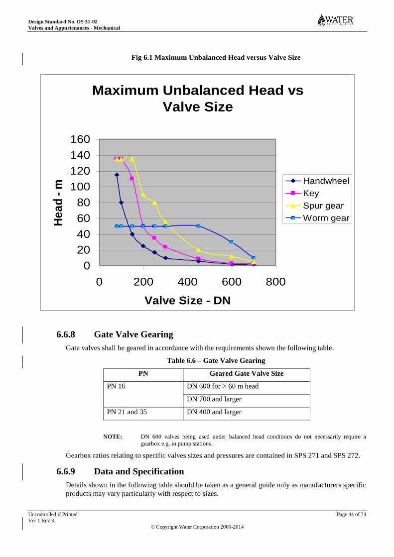
Design Standard No. DS 31-02
Valves and Appurtenances - Mechanical
Uncontrolled if Printed Page 44 of 74
Ver 1 Rev 3
© Copyright Water Corporation 2000-2014
Fig 6.1 Maximum Unbalanced Head versus Valve Size
6.6.8 Gate Valve Gearing
Gate valves shall be geared in accordance with the requirements shown the following table.
Table 6.6 – Gate Valve Gearing
PN Geared Gate Valve Size
PN 16 DN 600 for > 60 m head
DN 700 and larger
PN 21 and 35 DN 400 and larger
NOTE: DN 600 valves being used under balanced head conditions do not necessarily require a
gearbox e.g. in pump stations.
Gearbox ratios relating to specific valves sizes and pressures are contained in SPS 271 and SPS 272.
6.6.9 Data and Specification
Details shown in the following table should be taken as a general guide only as manufacturers specific
products may vary particularly with respect to sizes.
Maximum Unbalanced Head vs
Valve Size
0
20
40
60
80
100
120
140
160
0 200 400 600 800
Valve Size - DN
He
ad
- m
Handwheel
Key
Spur gear
Worm gear
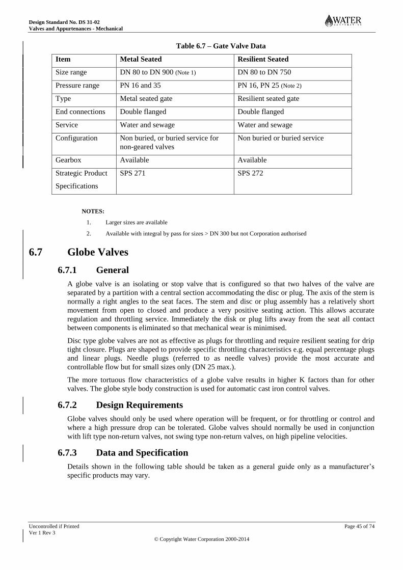
Design Standard No. DS 31-02
Valves and Appurtenances - Mechanical
Uncontrolled if Printed Page 45 of 74
Ver 1 Rev 3
© Copyright Water Corporation 2000-2014
Table 6.7 – Gate Valve Data
Item Metal Seated Resilient Seated
Size range DN 80 to DN 900 (Note 1) DN 80 to DN 750
Pressure range PN 16 and 35 PN 16, PN 25 (Note 2)
Type Metal seated gate Resilient seated gate
End connections Double flanged Double flanged
Service Water and sewage Water and sewage
Configuration Non buried, or buried service for
non-geared valves
Non buried or buried service
Gearbox Available Available
Strategic Product
Specifications
SPS 271 SPS 272
NOTES:
1. Larger sizes are available
2. Available with integral by pass for sizes > DN 300 but not Corporation authorised
6.7 Globe Valves
6.7.1 General
A globe valve is an isolating or stop valve that is configured so that two halves of the valve are
separated by a partition with a central section accommodating the disc or plug. The axis of the stem is
normally a right angles to the seat faces. The stem and disc or plug assembly has a relatively short
movement from open to closed and produce a very positive seating action. This allows accurate
regulation and throttling service. Immediately the disk or plug lifts away from the seat all contact
between components is eliminated so that mechanical wear is minimised.
Disc type globe valves are not as effective as plugs for throttling and require resilient seating for drip
tight closure. Plugs are shaped to provide specific throttling characteristics e.g. equal percentage plugs
and linear plugs. Needle plugs (referred to as needle valves) provide the most accurate and
controllable flow but for small sizes only (DN 25 max.).
The more tortuous flow characteristics of a globe valve results in higher K factors than for other
valves. The globe style body construction is used for automatic cast iron control valves.
6.7.2 Design Requirements
Globe valves should only be used where operation will be frequent, or for throttling or control and
where a high pressure drop can be tolerated. Globe valves should normally be used in conjunction
with lift type non-return valves, not swing type non-return valves, on high pipeline velocities.
6.7.3 Data and Specification
Details shown in the following table should be taken as a general guide only as a manufacturer’s
specific products may vary.
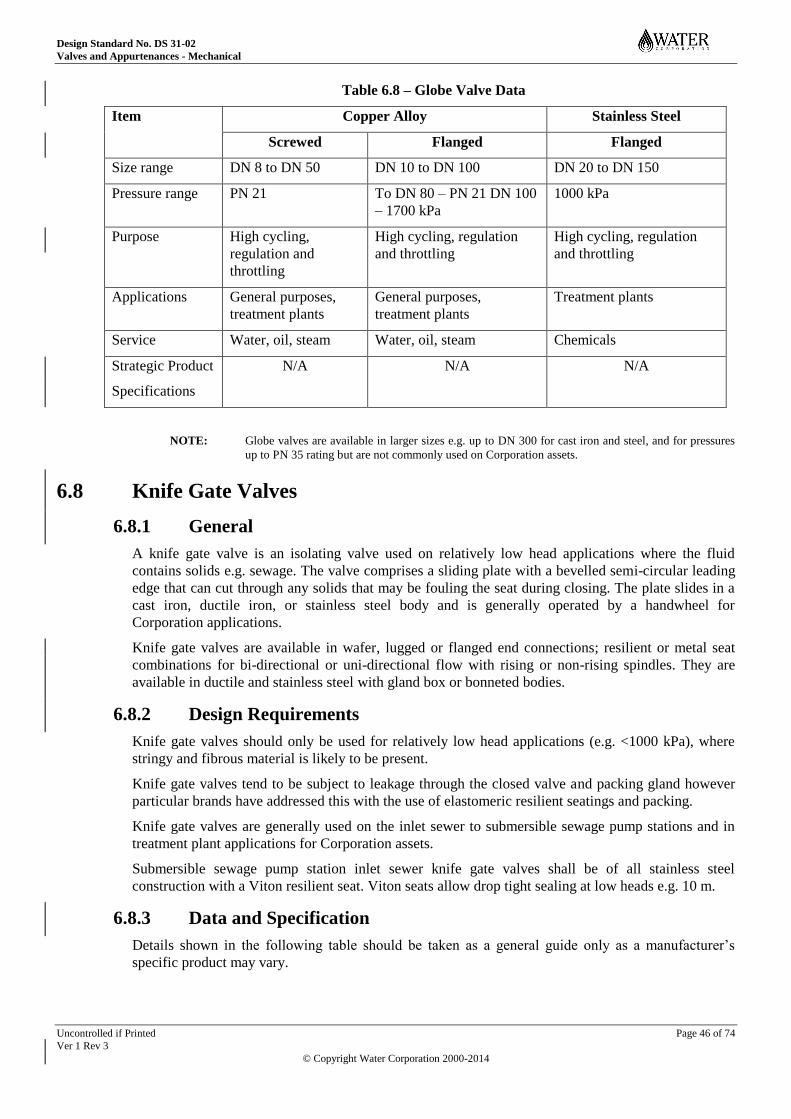
Design Standard No. DS 31-02
Valves and Appurtenances - Mechanical
Uncontrolled if Printed Page 46 of 74
Ver 1 Rev 3
© Copyright Water Corporation 2000-2014
Table 6.8 – Globe Valve Data
Item Copper Alloy Stainless Steel
Screwed Flanged Flanged
Size range DN 8 to DN 50 DN 10 to DN 100 DN 20 to DN 150
Pressure range PN 21 To DN 80 – PN 21 DN 100
– 1700 kPa
1000 kPa
Purpose High cycling,
regulation and
throttling
High cycling, regulation
and throttling
High cycling, regulation
and throttling
Applications General purposes,
treatment plants
General purposes,
treatment plants
Treatment plants
Service Water, oil, steam Water, oil, steam Chemicals
Strategic Product
Specifications
N/A N/A N/A
NOTE: Globe valves are available in larger sizes e.g. up to DN 300 for cast iron and steel, and for pressures
up to PN 35 rating but are not commonly used on Corporation assets.
6.8 Knife Gate Valves
6.8.1 General
A knife gate valve is an isolating valve used on relatively low head applications where the fluid
contains solids e.g. sewage. The valve comprises a sliding plate with a bevelled semi-circular leading
edge that can cut through any solids that may be fouling the seat during closing. The plate slides in a
cast iron, ductile iron, or stainless steel body and is generally operated by a handwheel for
Corporation applications.
Knife gate valves are available in wafer, lugged or flanged end connections; resilient or metal seat
combinations for bi-directional or uni-directional flow with rising or non-rising spindles. They are
available in ductile and stainless steel with gland box or bonneted bodies.
6.8.2 Design Requirements
Knife gate valves should only be used for relatively low head applications (e.g. <1000 kPa), where
stringy and fibrous material is likely to be present.
Knife gate valves tend to be subject to leakage through the closed valve and packing gland however
particular brands have addressed this with the use of elastomeric resilient seatings and packing.
Knife gate valves are generally used on the inlet sewer to submersible sewage pump stations and in
treatment plant applications for Corporation assets.
Submersible sewage pump station inlet sewer knife gate valves shall be of all stainless steel
construction with a Viton resilient seat. Viton seats allow drop tight sealing at low heads e.g. 10 m.
6.8.3 Data and Specification
Details shown in the following table should be taken as a general guide only as a manufacturer’s
specific product may vary.
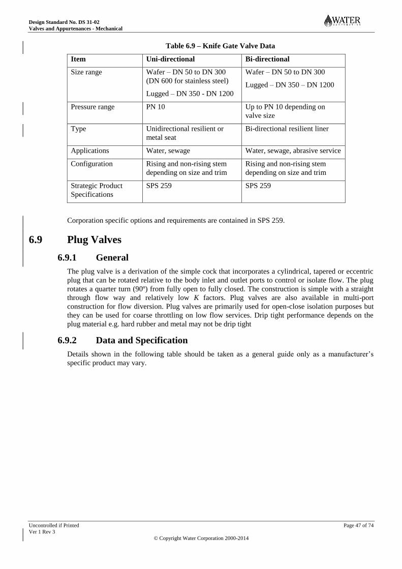
Design Standard No. DS 31-02
Valves and Appurtenances - Mechanical
Uncontrolled if Printed Page 47 of 74
Ver 1 Rev 3
© Copyright Water Corporation 2000-2014
Table 6.9 – Knife Gate Valve Data
Item Uni-directional Bi-directional
Size range Wafer – DN 50 to DN 300
(DN 600 for stainless steel)
Lugged – DN 350 - DN 1200
Wafer – DN 50 to DN 300
Lugged – DN 350 – DN 1200
Pressure range PN 10 Up to PN 10 depending on
valve size
Type Unidirectional resilient or
metal seat
Bi-directional resilient liner
Applications Water, sewage Water, sewage, abrasive service
Configuration Rising and non-rising stem
depending on size and trim
Rising and non-rising stem
depending on size and trim
Strategic Product
Specifications
SPS 259 SPS 259
Corporation specific options and requirements are contained in SPS 259.
6.9 Plug Valves
6.9.1 General
The plug valve is a derivation of the simple cock that incorporates a cylindrical, tapered or eccentric
plug that can be rotated relative to the body inlet and outlet ports to control or isolate flow. The plug
rotates a quarter turn (90º) from fully open to fully closed. The construction is simple with a straight
through flow way and relatively low K factors. Plug valves are also available in multi-port
construction for flow diversion. Plug valves are primarily used for open-close isolation purposes but
they can be used for coarse throttling on low flow services. Drip tight performance depends on the
plug material e.g. hard rubber and metal may not be drip tight
6.9.2 Data and Specification
Details shown in the following table should be taken as a general guide only as a manufacturer’s
specific product may vary.
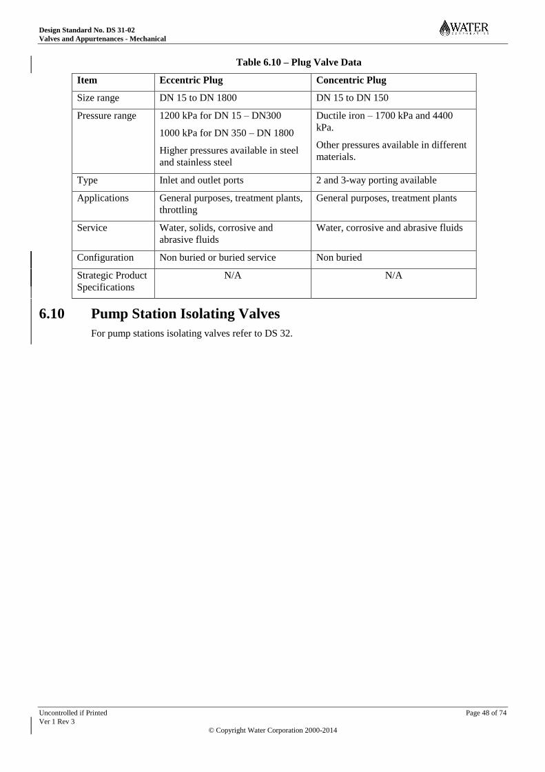
Design Standard No. DS 31-02
Valves and Appurtenances - Mechanical
Uncontrolled if Printed Page 48 of 74
Ver 1 Rev 3
© Copyright Water Corporation 2000-2014
Table 6.10 – Plug Valve Data
Item Eccentric Plug Concentric Plug
Size range DN 15 to DN 1800 DN 15 to DN 150
Pressure range 1200 kPa for DN 15 – DN300
1000 kPa for DN 350 – DN 1800
Higher pressures available in steel
and stainless steel
Ductile iron – 1700 kPa and 4400
kPa.
Other pressures available in different
materials.
Type Inlet and outlet ports 2 and 3-way porting available
Applications General purposes, treatment plants,
throttling
General purposes, treatment plants
Service Water, solids, corrosive and
abrasive fluids
Water, corrosive and abrasive fluids
Configuration Non buried or buried service Non buried
Strategic Product
Specifications
N/A N/A
6.10 Pump Station Isolating Valves
For pump stations isolating valves refer to DS 32.
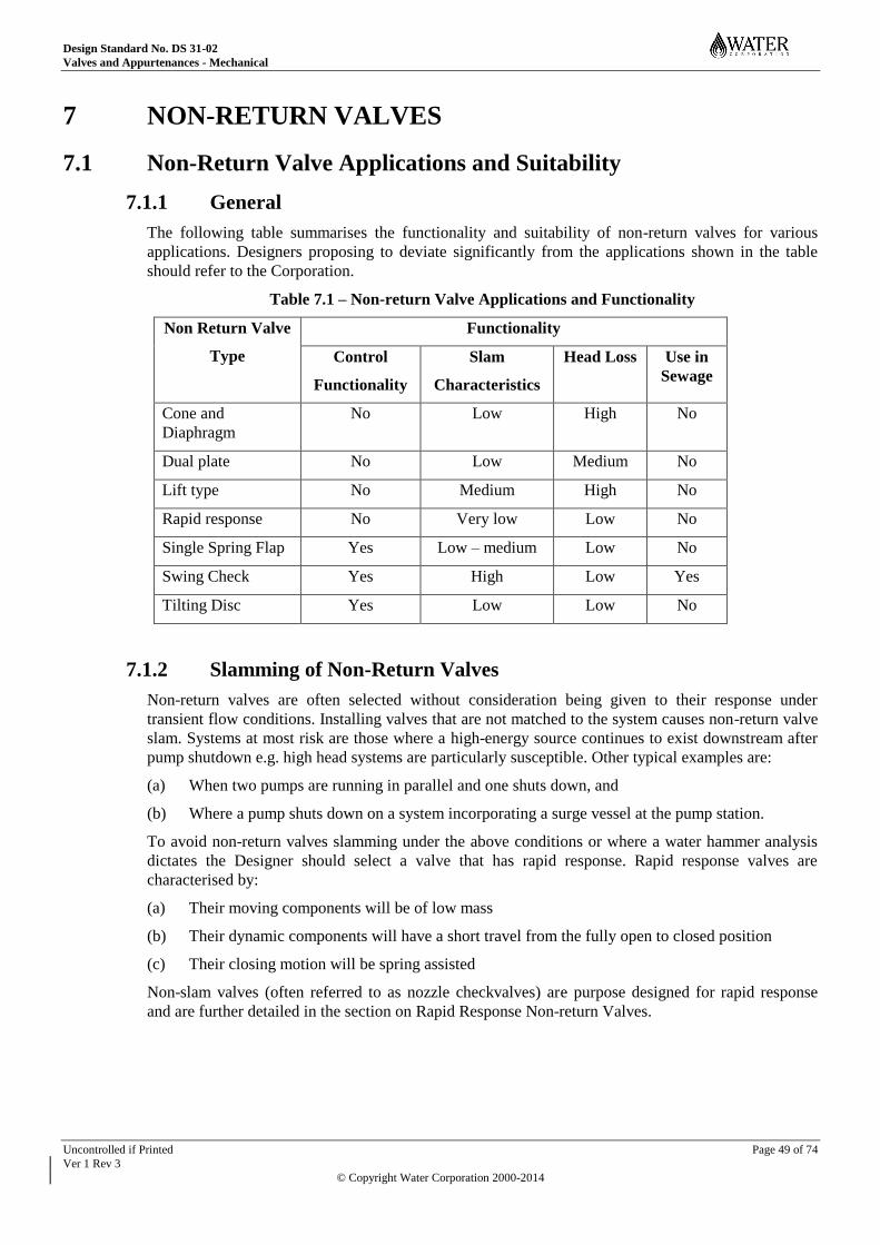
Design Standard No. DS 31-02
Valves and Appurtenances - Mechanical
Uncontrolled if Printed Page 49 of 74
Ver 1 Rev 3
© Copyright Water Corporation 2000-2014
7 NON-RETURN VALVES
7.1 Non-Return Valve Applications and Suitability
7.1.1 General
The following table summarises the functionality and suitability of non-return valves for various
applications. Designers proposing to deviate significantly from the applications shown in the table
should refer to the Corporation.
Table 7.1 – Non-return Valve Applications and Functionality
Non Return Valve
Type
Functionality
Control
Functionality
Slam
Characteristics
Head Loss Use in
Sewage
Cone and
Diaphragm
No Low High No
Dual plate No Low Medium No
Lift type No Medium High No
Rapid response No Very low Low No
Single Spring Flap Yes Low – medium Low No
Swing Check Yes High Low Yes
Tilting Disc Yes Low Low No
7.1.2 Slamming of Non-Return Valves
Non-return valves are often selected without consideration being given to their response under
transient flow conditions. Installing valves that are not matched to the system causes non-return valve
slam. Systems at most risk are those where a high-energy source continues to exist downstream after
pump shutdown e.g. high head systems are particularly susceptible. Other typical examples are:
(a) When two pumps are running in parallel and one shuts down, and
(b) Where a pump shuts down on a system incorporating a surge vessel at the pump station.
To avoid non-return valves slamming under the above conditions or where a water hammer analysis
dictates the Designer should select a valve that has rapid response. Rapid response valves are
characterised by:
(a) Their moving components will be of low mass
(b) Their dynamic components will have a short travel from the fully open to closed position
(c) Their closing motion will be spring assisted
Non-slam valves (often referred to as nozzle checkvalves) are purpose designed for rapid response
and are further detailed in the section on Rapid Response Non-return Valves.
Design Standard No. DS 31-02
Valves and Appurtenances - Mechanical
Uncontrolled if Printed Page 50 of 74
Ver 1 Rev 3
© Copyright Water Corporation 2000-2014
7.2 Cone and Diaphragm Non-Return Valve
7.2.1 General
The cone and diaphragm non-return valve is a flangeless wafer type non-return valve that comprises a
conical perforated stainless steel body containing a thin rubber diaphragm fixed at the apex of the
cone. Flow direction is from the apex end passing through the perforated body causing collapse of the
diaphragm and relatively free flow. Reverse flow flattens the diaphragm against the body closing the
valve and stopping the flow.
7.2.2 Application
Cone and diaphragm non-return valves are suitable for clean water applications only. It is a general-
purpose valve used on small pipelines.
7.2.3 Features
Physical features of the cone and diaphragm type non-return valves are detailed in the following table.
Table 7.2 Features of Cone and Diaphragm Non-return Valves
Specification Cone and Diaphragm Non-Return Valve
Size range DN 80 – DN 150
Pressure/PN PN 14/16
End connections Wafer
Body style Compact
Head loss High
Orientation Horizontal or vertical (Refer Note)
Flow control functionality Not available
Termination style No
Complexity Simple
Ease of maintenance Simple
Low head sealing Good
Drip tight sealing Yes
Direct burial Yes but not normally buried
Water hammer susceptibility Low
Maintenance Low
Noise Low
NOTE: This valve can be installed with the flow vertically downwards.
7.2.4 Design Criteria
These valves should not be used where blockage is likely because of the strainer effect of the body
e.g. should not be used on sewage.
Excessive turbulence should be avoided as it could cause premature failure of the membrane to
fastener joint.
Design Standard No. DS 31-02
Valves and Appurtenances - Mechanical
Uncontrolled if Printed Page 51 of 74
Ver 1 Rev 3
© Copyright Water Corporation 2000-2014
7.3 Damped Swing Check Non-Return Valves
Damped or cushioned swing check non-return valves are purpose-built to provide controlled closing
via an air or oil type damper system to eliminate slamming. The valves are heavy duty to resist shock
and the damper system is field adjustable to vary the rate of closure. The valve flow characteristics
are the same as for a swing check valve.
The air damper is designed to provide rapid response for general applications whereas the oil damped
system is for more severe rapid response applications such as would occur with rapid flow reversal at
pump shut off e.g. effect of a nearby surge vessel.
Damped swing check non-return valves are suitable for water and sewage applications and available
in sizes from DN 200 to DN 1600. For further details refer to relevant manufacturers published
information
7.4 Dual Plate (Flap) Non-Return Valve
7.4.1 General
The dual plate non-return valve comprises two spring loaded semi-circular plates hinged from a
centrally mounted post in a wafer or double flanged spool type body. The plates seal against a
resilient seal in the body. The characteristics of this valve are compactness and rapid response to
reverse flow so they tend to be low slam. They are not suitable for flow control monitoring or control.
7.4.2 Specification
Dual plate non-return valves shall comply with SPS 226.
7.4.3 Applications
Dual plate non-return valves should be used for general purpose clean water applications only. They
shall not be used for sewage applications.
Dual plate non return valves should not be used where extended shafts are required. If an extended
shaft is required then a swing check valve should be used providing slamming is not an issue.
Dual plate non-return valves may be buried to avoid pit costs where circumstances are favourable e.g.
bypass line around a pump station or in a pipeline external to the pump station.
7.4.4 Features
Features of dual plate non-return valves are detailed in the following table.
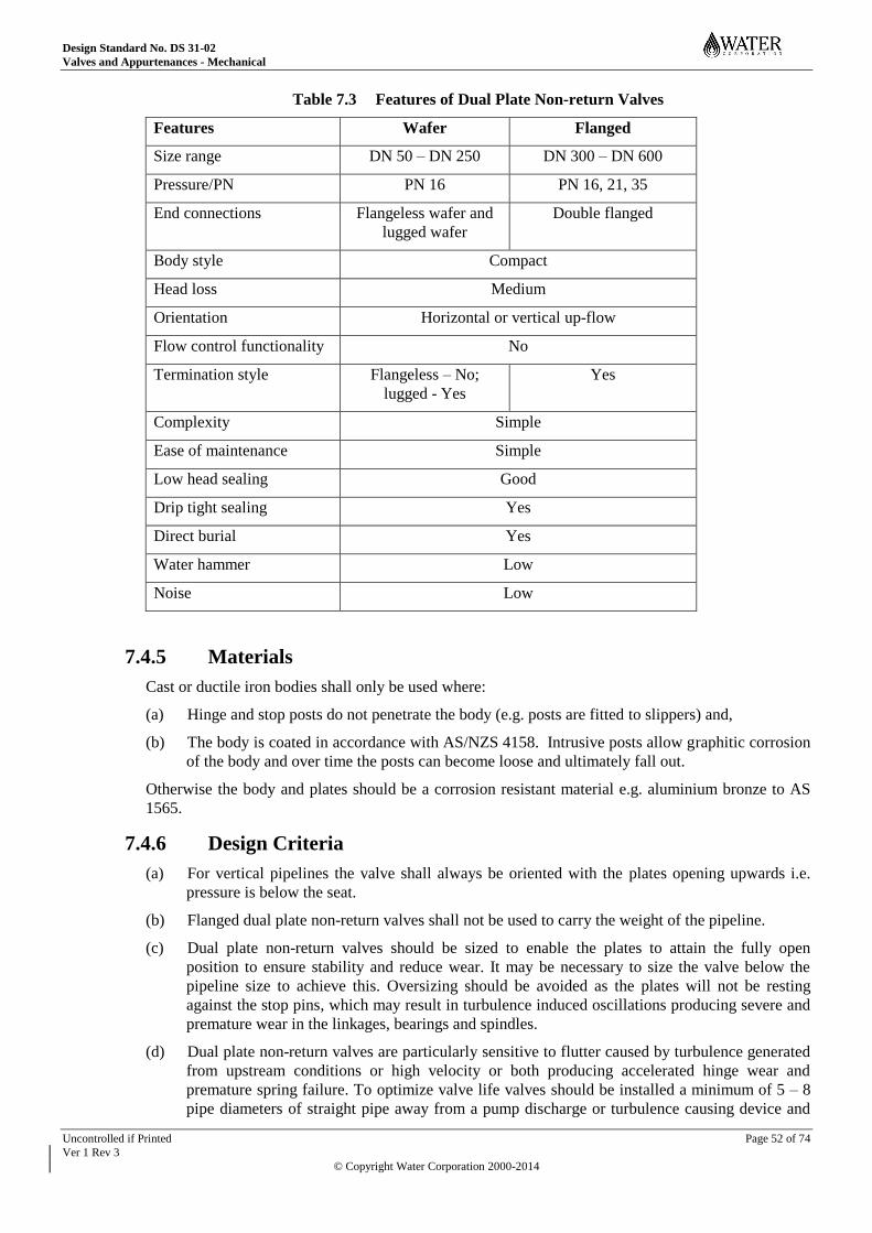
Design Standard No. DS 31-02
Valves and Appurtenances - Mechanical
Uncontrolled if Printed Page 52 of 74
Ver 1 Rev 3
© Copyright Water Corporation 2000-2014
Table 7.3 Features of Dual Plate Non-return Valves
Features Wafer Flanged
Size range DN 50 – DN 250 DN 300 – DN 600
Pressure/PN PN 16 PN 16, 21, 35
End connections Flangeless wafer and
lugged wafer
Double flanged
Body style Compact
Head loss Medium
Orientation Horizontal or vertical up-flow
Flow control functionality No
Termination style Flangeless – No;
lugged - Yes
Yes
Complexity Simple
Ease of maintenance Simple
Low head sealing Good
Drip tight sealing Yes
Direct burial Yes
Water hammer Low
Noise Low
7.4.5 Materials
Cast or ductile iron bodies shall only be used where:
(a) Hinge and stop posts do not penetrate the body (e.g. posts are fitted to slippers) and,
(b) The body is coated in accordance with AS/NZS 4158. Intrusive posts allow graphitic corrosion
of the body and over time the posts can become loose and ultimately fall out.
Otherwise the body and plates should be a corrosion resistant material e.g. aluminium bronze to AS
1565.
7.4.6 Design Criteria
(a) For vertical pipelines the valve shall always be oriented with the plates opening upwards i.e.
pressure is below the seat.
(b) Flanged dual plate non-return valves shall not be used to carry the weight of the pipeline.
(c) Dual plate non-return valves should be sized to enable the plates to attain the fully open
position to ensure stability and reduce wear. It may be necessary to size the valve below the
pipeline size to achieve this. Oversizing should be avoided as the plates will not be resting
against the stop pins, which may result in turbulence induced oscillations producing severe and
premature wear in the linkages, bearings and spindles.
(d) Dual plate non-return valves are particularly sensitive to flutter caused by turbulence generated
from upstream conditions or high velocity or both producing accelerated hinge wear and
premature spring failure. To optimize valve life valves should be installed a minimum of 5 – 8
pipe diameters of straight pipe away from a pump discharge or turbulence causing device and
Design Standard No. DS 31-02
Valves and Appurtenances - Mechanical
Uncontrolled if Printed Page 53 of 74
Ver 1 Rev 3
© Copyright Water Corporation 2000-2014
should not be exposed to velocities greater than 3.5 m/s (maximum flow should normally not
exceed 2.5 m/s).
(e) For normal dynamic response applications standard springs should be used. However where
high system decelerations exist valves require fast dynamic response and therefore maximum
torque springs should be used. Valve sizes above DN 100 shall incorporate 2 or more
independent springs to operate the plates. On the larger valves a single spring can cause
excessive diverse velocities through the plates’ waterways causing uneven closure of the plates.
(f) For backpressures <10 m the valve should be fitted with low torque springs, hand lapping of
seat faces and low head hydrostatic performance testing (which entails filling the valve body
with water whilst it is in the vertical up-flow position and checking for leakage).
7.5 Lift Type Non-Return Valve
7.5.1 General
In the context of this Standard lift type non return valve refers to a copper alloy non-return valve in
which the disc and body seat is configured similar to a globe valve except that the disc, which is
guided, is free to move axially. Flow lifts the disc from its seat whilst no flow or reverse flow causes
it to return to the seat thus preventing backflow. Like the globe valve the flow path is tortuous and
correspondingly the K factors are higher than other valves.
The lift type non-return valve allows a tighter more positive seal than a swing type. Horizontal lift
non-return valves should be installed in horizontal pipelines with the disc axis vertical however
specific vertical or angle type valves are available.
Lift non-return valves should be used in conjunction with globe valves in high velocity pipeline
applications.
7.5.2 Specification
The lift type non-return valve shall comply with SPS 220, which references AS 1628.
7.5.3 Application
Lift type non-return valves are suitable for water only.
7.5.4 Features
Physical features of lift type non-return valves are detailed in the following table.
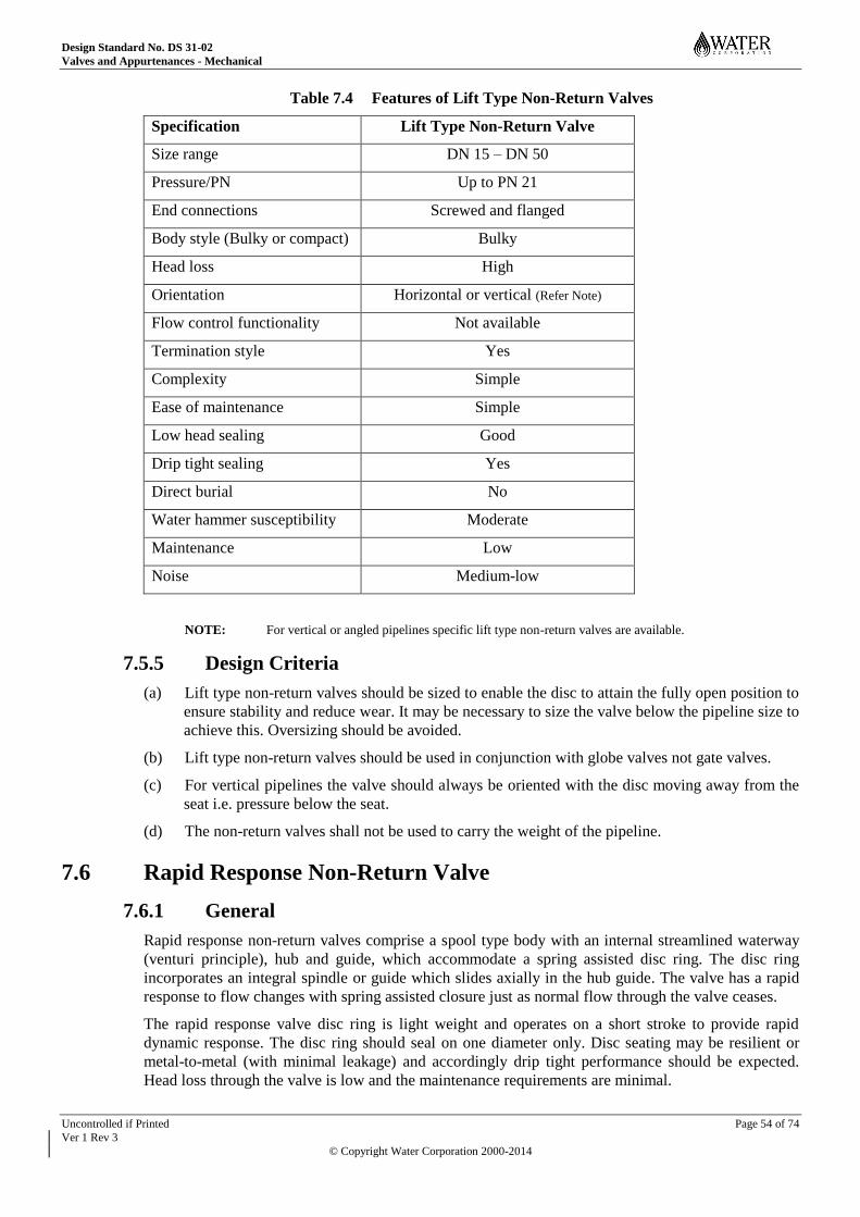
Design Standard No. DS 31-02
Valves and Appurtenances - Mechanical
Uncontrolled if Printed Page 54 of 74
Ver 1 Rev 3
© Copyright Water Corporation 2000-2014
Table 7.4 Features of Lift Type Non-Return Valves
Specification Lift Type Non-Return Valve
Size range DN 15 – DN 50
Pressure/PN Up to PN 21
End connections Screwed and flanged
Body style (Bulky or compact) Bulky
Head loss High
Orientation Horizontal or vertical (Refer Note)
Flow control functionality Not available
Termination style Yes
Complexity Simple
Ease of maintenance Simple
Low head sealing Good
Drip tight sealing Yes
Direct burial No
Water hammer susceptibility Moderate
Maintenance Low
Noise Medium-low
NOTE: For vertical or angled pipelines specific lift type non-return valves are available.
7.5.5 Design Criteria
(a) Lift type non-return valves should be sized to enable the disc to attain the fully open position to
ensure stability and reduce wear. It may be necessary to size the valve below the pipeline size to
achieve this. Oversizing should be avoided.
(b) Lift type non-return valves should be used in conjunction with globe valves not gate valves.
(c) For vertical pipelines the valve should always be oriented with the disc moving away from the
seat i.e. pressure below the seat.
(d) The non-return valves shall not be used to carry the weight of the pipeline.
7.6 Rapid Response Non-Return Valve
7.6.1 General
Rapid response non-return valves comprise a spool type body with an internal streamlined waterway
(venturi principle), hub and guide, which accommodate a spring assisted disc ring. The disc ring
incorporates an integral spindle or guide which slides axially in the hub guide. The valve has a rapid
response to flow changes with spring assisted closure just as normal flow through the valve ceases.
The rapid response valve disc ring is light weight and operates on a short stroke to provide rapid
dynamic response. The disc ring should seal on one diameter only. Disc seating may be resilient or
metal-to-metal (with minimal leakage) and accordingly drip tight performance should be expected.
Head loss through the valve is low and the maintenance requirements are minimal.

Design Standard No. DS 31-02
Valves and Appurtenances - Mechanical
Uncontrolled if Printed Page 55 of 74
Ver 1 Rev 3
© Copyright Water Corporation 2000-2014
7.6.2 Specification
Rapid response non-return valves shall comply with SPS 230.
7.6.3 Application
Rapid response non-return valves are:
(a) Suitable for clear water applications e.g. drinking, raw and recycled water only. They shall not
be used for sewage.
(b) Used where system decelerations is 5 m/s2 or higher.
(c) Used for environmental reasons where it is desirable to minimize noise during normal flow
conditions or upon closure of the valve.
(d) Rapid response non-return valves may be buried to avoid pit costs where circumstances are
favourable e.g. bypass line around a pump station or in a pipeline external to the pump station.
7.6.4 Features
Physical features of rapid response valves non-return valves are detailed in the following table.
Table 7.5 Features of Rapid Response Non-return Valves
Specification Rapid Response Non-Return Valve
Size range DN 400 – DN 1200
Pressure/PN PN 16, 21, 35
End connections Double flanged
Body style Compact or long body styles
Head loss Low
Orientation Horizontal, vertical or inclined
Flow control functionality Not available
Termination style Yes
Complexity Simple
Ease of maintenance Simple
Low head sealing Good
Drip tight sealing Yes (bubble tight)
Direct burial Yes
Water hammer susceptibility Very low
Maintenance Very low
Noise Low
7.6.5 Design Criteria
(a) Rapid response valves are normally used in horizontal pipelines however for vertical pipelines
valves shall be oriented with the disc opening upwards i.e. pressure below the seat.

Design Standard No. DS 31-02
Valves and Appurtenances - Mechanical
Uncontrolled if Printed Page 56 of 74
Ver 1 Rev 3
© Copyright Water Corporation 2000-2014
(b) The valves shall not be used to carry the weight of the pipeline or to resist couples as a result of
lack of pipework restraint. Rapid response valves can be installed a minimum of 2 pipe
diameters downstream of a turbulence generator e.g. pump, bend etc.
(c) A water hammer analysis shall be conducted to identify the need for a rapid response non-
return valve. Rapid response valves are relatively expensive and if a swing check or dual plate
(flap) valve is identified as suitable then they should be used.
(d) Deceleration values shall be obtained during the water hammer analysis in order to select the
proper spring rating for optimal closure and water hammer mitigation. Manufacturers shall be
provided with accurate data for correct spring selection by the Designer. In addition to
deceleration values data shall include minimum flow rate, maximum flow rate and most
importantly normal flow rate. Normal flow rate is extremely important in that given minimum
and maximum flow rates only a manufacturer may be tempted to the take an average to
determine normal flow rate. However if the actual normal flow rate is nearer to either the low
or high end of the flow range, spring related operational problems may occur,
(e) The Designer should ensure the stem guide and stem are manufactured from materials that will
not produce galling due to the combination of mutual contact and relative motion. The
Corporation has experienced this problem. Refer to Stainless Steel in the Materials section of
DS 30-02 for further information regarding galling.
(f) These valves should require minimal maintenance therefore effective coating of the cast iron
body is critical to ensure long life by minimising graphitic corrosion.
7.6.6 Valve Selection
7.6.6.1 Flow Velocities
The valve shall be selected to operate within the following velocity boundaries:
(a) The minimum steady state velocity shall be determined on the basis of the critical velocity, V0
required to fully open valve, based on the valve inlet diameter, Di.
V0 shall not exceed 0.8 times the minimum steady state velocity of the pipe. Preferred values of
V0 are between 0.7 and 0.8. Lower values of V0 are to be avoided.
(b) The maximum steady state velocity in the valve shall not exceed 5.0 m/s
Vo
Vmin
> 1.25 Vo
Vmax
< 5.0 m/s
He
ad
Lo
ss
Velocity
Valve partially open
Normal Operating Range
Fig 7.1 – Flow Velocities
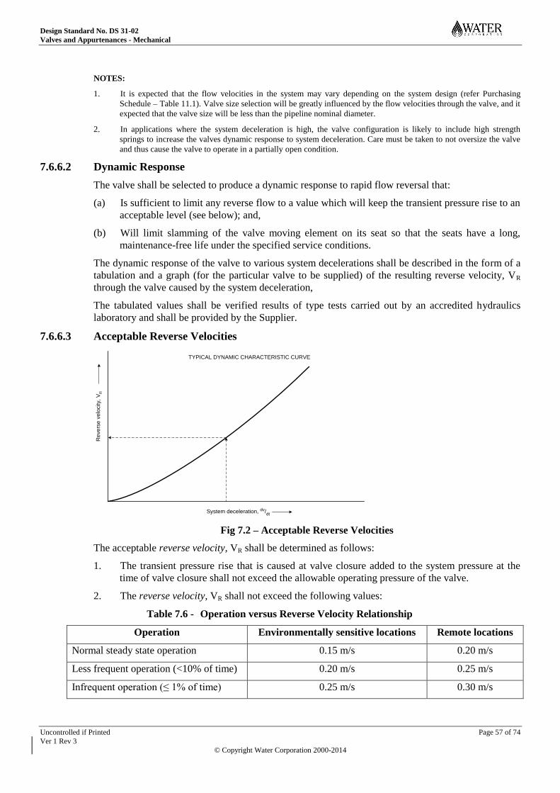
Design Standard No. DS 31-02
Valves and Appurtenances - Mechanical
Uncontrolled if Printed Page 57 of 74
Ver 1 Rev 3
© Copyright Water Corporation 2000-2014
NOTES:
1. It is expected that the flow velocities in the system may vary depending on the system design (refer Purchasing
Schedule – Table 11.1). Valve size selection will be greatly influenced by the flow velocities through the valve, and it
expected that the valve size will be less than the pipeline nominal diameter.
2. In applications where the system deceleration is high, the valve configuration is likely to include high strength
springs to increase the valves dynamic response to system deceleration. Care must be taken to not oversize the valve
and thus cause the valve to operate in a partially open condition.
7.6.6.2 Dynamic Response
The valve shall be selected to produce a dynamic response to rapid flow reversal that:
(a) Is sufficient to limit any reverse flow to a value which will keep the transient pressure rise to an
acceptable level (see below); and,
(b) Will limit slamming of the valve moving element on its seat so that the seats have a long,
maintenance-free life under the specified service conditions.
The dynamic response of the valve to various system decelerations shall be described in the form of a
tabulation and a graph (for the particular valve to be supplied) of the resulting reverse velocity, VR
through the valve caused by the system deceleration,
The tabulated values shall be verified results of type tests carried out by an accredited hydraulics
laboratory and shall be provided by the Supplier.
7.6.6.3 Acceptable Reverse Velocities
System deceleration, dv/dt
Re
ve
rse
ve
locity, V
R
TYPICAL DYNAMIC CHARACTERISTIC CURVE
Fig 7.2 – Acceptable Reverse Velocities
The acceptable reverse velocity, VR shall be determined as follows:
1. The transient pressure rise that is caused at valve closure added to the system pressure at the
time of valve closure shall not exceed the allowable operating pressure of the valve.
2. The reverse velocity, VR shall not exceed the following values:
Table 7.6 - Operation versus Reverse Velocity Relationship
Operation Environmentally sensitive locations Remote locations
Normal steady state operation 0.15 m/s 0.20 m/s
Less frequent operation (<10% of time) 0.20 m/s 0.25 m/s
Infrequent operation (≤ 1% of time) 0.25 m/s 0.30 m/s
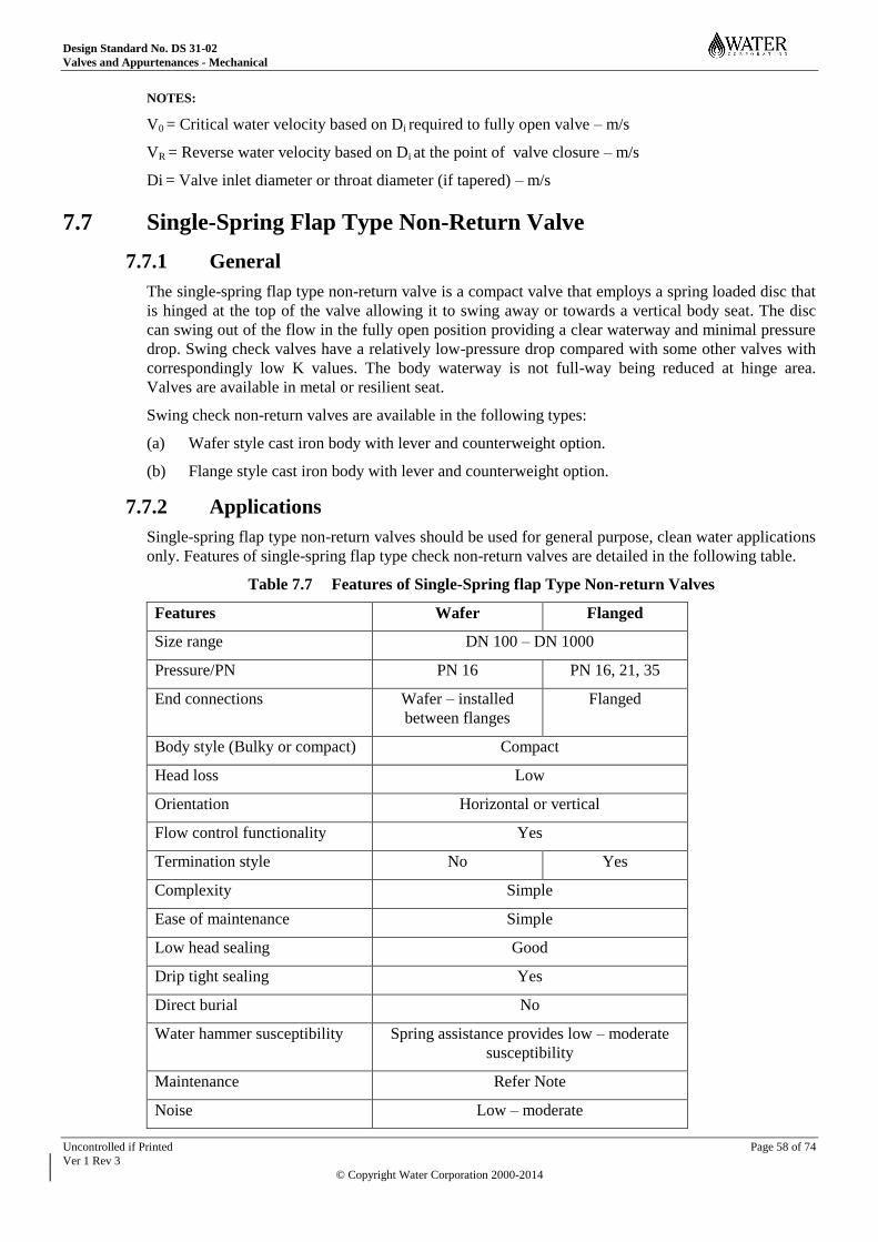
Design Standard No. DS 31-02
Valves and Appurtenances - Mechanical
Uncontrolled if Printed Page 58 of 74
Ver 1 Rev 3
© Copyright Water Corporation 2000-2014
NOTES:
V0 = Critical water velocity based on Di required to fully open valve – m/s
VR = Reverse water velocity based on Di at the point of valve closure – m/s
Di = Valve inlet diameter or throat diameter (if tapered) – m/s
7.7 Single-Spring Flap Type Non-Return Valve
7.7.1 General
The single-spring flap type non-return valve is a compact valve that employs a spring loaded disc that
is hinged at the top of the valve allowing it to swing away or towards a vertical body seat. The disc
can swing out of the flow in the fully open position providing a clear waterway and minimal pressure
drop. Swing check valves have a relatively low-pressure drop compared with some other valves with
correspondingly low K values. The body waterway is not full-way being reduced at hinge area.
Valves are available in metal or resilient seat.
Swing check non-return valves are available in the following types:
(a) Wafer style cast iron body with lever and counterweight option.
(b) Flange style cast iron body with lever and counterweight option.
7.7.2 Applications
Single-spring flap type non-return valves should be used for general purpose, clean water applications
only. Features of single-spring flap type check non-return valves are detailed in the following table.
Table 7.7 Features of Single-Spring flap Type Non-return Valves
Features Wafer Flanged
Size range DN 100 – DN 1000
Pressure/PN PN 16 PN 16, 21, 35
End connections Wafer – installed
between flanges
Flanged
Body style (Bulky or compact) Compact
Head loss Low
Orientation Horizontal or vertical
Flow control functionality Yes
Termination style No Yes
Complexity Simple
Ease of maintenance Simple
Low head sealing Good
Drip tight sealing Yes
Direct burial No
Water hammer susceptibility Spring assistance provides low – moderate
susceptibility
Maintenance Refer Note
Noise Low – moderate
Design Standard No. DS 31-02
Valves and Appurtenances - Mechanical
Uncontrolled if Printed Page 59 of 74
Ver 1 Rev 3
© Copyright Water Corporation 2000-2014
NOTE: Hinge wear, corrosion of cast iron, severe tuberculation of cast iron wetted surfaces may occur if not
properly coated, and resilient seats can dislodge.
7.7.3 Materials
Cast iron bodies should not be used unless they are provided with a good quality coating to prevent
tuberculation.
7.7.4 Design Criteria
(a) For vertical pipelines the valve shall always be oriented with the disc opening upwards i.e.
pressure is below the seat.
(b) Flanged non-return valves shall not be used to carry the weight of the pipeline.
(c) Single flap swing check valves should sized to enable the disc to attain the fully open position
to ensure stability and reduce wear. It may be necessary to size the valve below the pipeline size
to achieve this. Oversizing should be avoided as the valve will drop into the flow, which may
produce turbulence induced oscillations producing severe and premature wear of the spindle
and bushes.
(d) Single-spring flap type non-return valves are sensitive to flutter with associated hinge wear and
spring failure and therefore should be installed a minimum of 4 – 5 pipe diameters of straight
pipe away from a pump discharge or turbulence causing device.
7.8 Swing Check Non-Return Valve
7.8.1 General
Is a non-return valve that employs a disc that is hinged at the top of the valve allowing it to swing
away or towards an angled body seat. The disc can swing out of the flow in the fully open position
providing a clear waterway and minimal pressure drop. Swing check valves have a lower pressure
drop than other valves with correspondingly lower K values.
Swing check non-return valves are available in the following types:
(a) Copper alloy
(b) Cast iron body type with metal disc
(c) Cast iron body type with resilient disc
7.8.2 Specification
The copper alloy type non-return valve shall comply with SPS 220. The cast iron body type non-
return valve, comprising either metal or resilient disc and hinge assembly, shall comply with SPS 223.
7.8.3 Application
Swing check non-return valves are suitable for water and sewage (Note - copper alloy non-return
valves shall not be used in sewage).
For very large sewage pump stations alternative non-return valves may have to be considered in lieu
of the swing check type. Alternatives such as relatively quick closing electrically or hydraulically
operated gate valves or plug valves, with pneumatic back up in the event of power failure may be
required. Piston damped swing check non-return valves are also available but are relatively expensive
in large sizes.
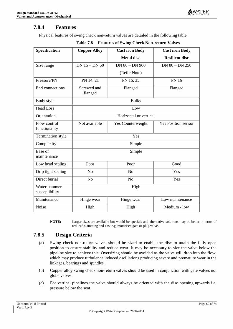
Design Standard No. DS 31-02
Valves and Appurtenances - Mechanical
Uncontrolled if Printed Page 60 of 74
Ver 1 Rev 3
© Copyright Water Corporation 2000-2014
7.8.4 Features
Physical features of swing check non-return valves are detailed in the following table.
Table 7.8 Features of Swing Check Non-return Valves
Specification Copper Alloy Cast iron Body
Metal disc
Cast iron Body
Resilient disc
Size range DN 15 – DN 50 DN 80 – DN 900
(Refer Note)
DN 80 – DN 250
Pressure/PN PN 14, 21 PN 16, 35 PN 16
End connections Screwed and
flanged
Flanged Flanged
Body style Bulky
Head Loss Low
Orientation Horizontal or vertical
Flow control
functionality
Not available Yes Counterweight Yes Position sensor
Termination style Yes
Complexity Simple
Ease of
maintenance
Simple
Low head sealing Poor Poor Good
Drip tight sealing No No Yes
Direct burial No No Yes
Water hammer
susceptibility
High
Maintenance Hinge wear Hinge wear Low maintenance
Noise High High Medium - low
NOTE: Larger sizes are available but would be specials and alternative solutions may be better in terms of
reduced slamming and cost e.g. motorised gate or plug valve.
7.8.5 Design Criteria
(a) Swing check non-return valves should be sized to enable the disc to attain the fully open
position to ensure stability and reduce wear. It may be necessary to size the valve below the
pipeline size to achieve this. Oversizing should be avoided as the valve will drop into the flow,
which may produce turbulence induced oscillations producing severe and premature wear in the
linkages, bearings and spindles.
(b) Copper alloy swing check non-return valves should be used in conjunction with gate valves not
globe valves.
(c) For vertical pipelines the valve should always be oriented with the disc opening upwards i.e.
pressure below the seat.

Design Standard No. DS 31-02
Valves and Appurtenances - Mechanical
Uncontrolled if Printed Page 61 of 74
Ver 1 Rev 3
© Copyright Water Corporation 2000-2014
(d) Vertical orientation should not be used for sewage application, as debris is likely to settle on
the disc causing fouling of the seat and leakage.
(e) Fluid velocities should be low and non-pulsating otherwise hinge wear will be excessive.
(f) Swing check non-return valves should not be used where water hammer is likely.
(g) The non-return valves shall not be used to carry the weight of the pipeline.
(h) Swing check non-return valves are particularly sensitive to flutter with associated hinge wear
and therefore should be installed a minimum of 4 – 5 pipe diameters of straight pipe away from
a pump discharge or turbulence causing device.
7.9 Tilting Disc Non-Return Valve
7.9.1 General
Is a type of swing check non-return valve that has its disc pivoted in front of the centre of pressure
and is counterweighted on the shaft to close. The disc pivots in the valve waterway and incorporates
an aerofoil shape that lifts or floats it thus providing minimum resistance to flow. The disc is balanced
such that it will close just before flow has ceased and reverse flow commences. The disc swing
geometry and seat angle provides conical seat lift valve type closure.
Characteristics of this valve are low-pressure drop at low flows and rapid response to flow reversal
producing a smooth and silent operation under all conditions. They are not suitable for sewage and
tend to resist opening when operating at low heads or with age, probably associated with wear. The
Corporation has opted to use alternative non-return valves to the tilting disc.
7.9.2 Specification
The tilting disc non-return valves are detailed AS 4794.
7.9.3 Application
Tilting disc non-return valve are only used in clear water applications and are not suitable for sewage.
7.9.4 Features
Physical features of tilting disc non-return valves are detailed in the following table.
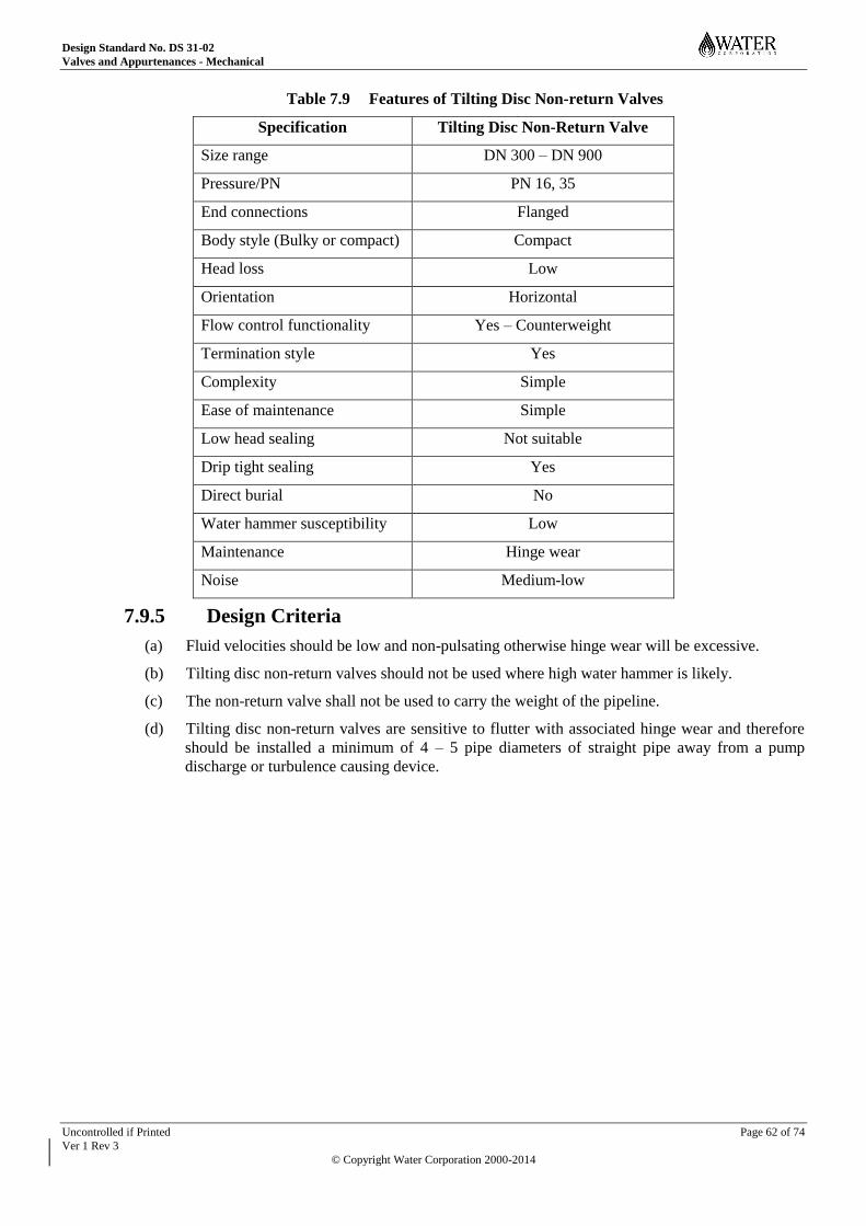
Design Standard No. DS 31-02
Valves and Appurtenances - Mechanical
Uncontrolled if Printed Page 62 of 74
Ver 1 Rev 3
© Copyright Water Corporation 2000-2014
Table 7.9 Features of Tilting Disc Non-return Valves
Specification Tilting Disc Non-Return Valve
Size range DN 300 – DN 900
Pressure/PN PN 16, 35
End connections Flanged
Body style (Bulky or compact) Compact
Head loss Low
Orientation Horizontal
Flow control functionality Yes – Counterweight
Termination style Yes
Complexity Simple
Ease of maintenance Simple
Low head sealing Not suitable
Drip tight sealing Yes
Direct burial No
Water hammer susceptibility Low
Maintenance Hinge wear
Noise Medium-low
7.9.5 Design Criteria
(a) Fluid velocities should be low and non-pulsating otherwise hinge wear will be excessive.
(b) Tilting disc non-return valves should not be used where high water hammer is likely.
(c) The non-return valve shall not be used to carry the weight of the pipeline.
(d) Tilting disc non-return valves are sensitive to flutter with associated hinge wear and therefore
should be installed a minimum of 4 – 5 pipe diameters of straight pipe away from a pump
discharge or turbulence causing device.
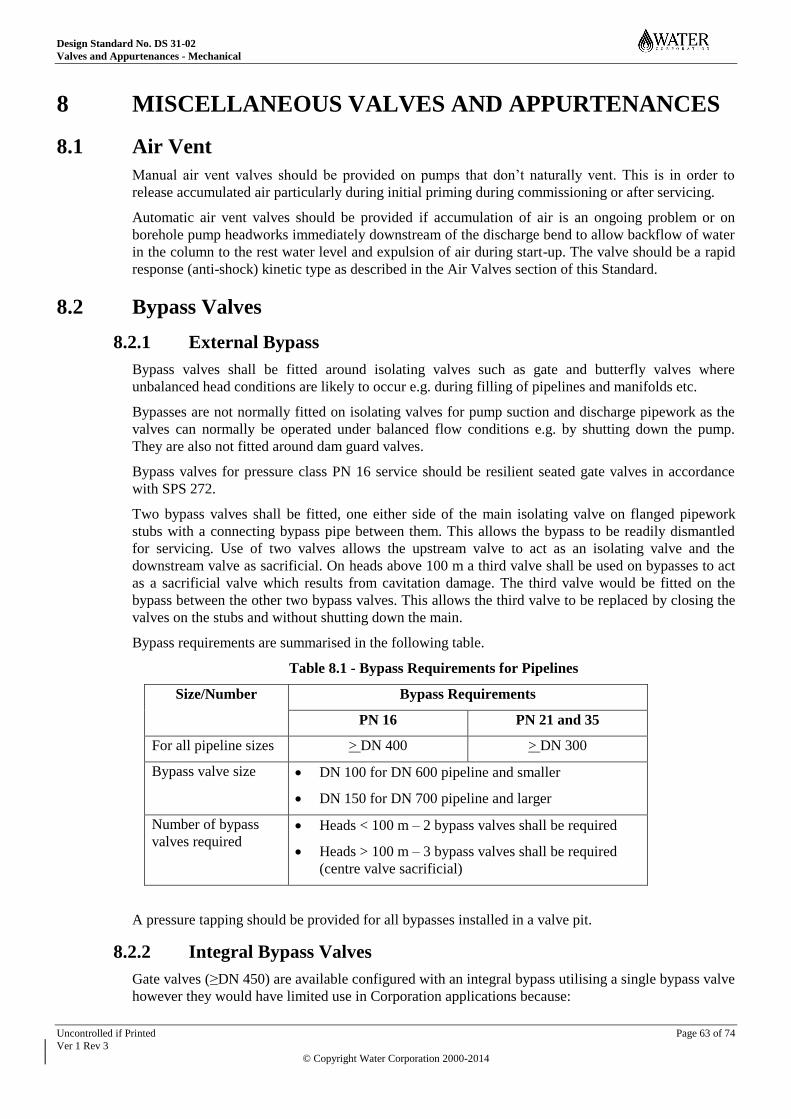
Design Standard No. DS 31-02
Valves and Appurtenances - Mechanical
Uncontrolled if Printed Page 63 of 74
Ver 1 Rev 3
© Copyright Water Corporation 2000-2014
8 MISCELLANEOUS VALVES AND APPURTENANCES
8.1 Air Vent
Manual air vent valves should be provided on pumps that don’t naturally vent. This is in order to
release accumulated air particularly during initial priming during commissioning or after servicing.
Automatic air vent valves should be provided if accumulation of air is an ongoing problem or on
borehole pump headworks immediately downstream of the discharge bend to allow backflow of water
in the column to the rest water level and expulsion of air during start-up. The valve should be a rapid
response (anti-shock) kinetic type as described in the Air Valves section of this Standard.
8.2 Bypass Valves
8.2.1 External Bypass
Bypass valves shall be fitted around isolating valves such as gate and butterfly valves where
unbalanced head conditions are likely to occur e.g. during filling of pipelines and manifolds etc.
Bypasses are not normally fitted on isolating valves for pump suction and discharge pipework as the
valves can normally be operated under balanced flow conditions e.g. by shutting down the pump.
They are also not fitted around dam guard valves.
Bypass valves for pressure class PN 16 service should be resilient seated gate valves in accordance
with SPS 272.
Two bypass valves shall be fitted, one either side of the main isolating valve on flanged pipework
stubs with a connecting bypass pipe between them. This allows the bypass to be readily dismantled
for servicing. Use of two valves allows the upstream valve to act as an isolating valve and the
downstream valve as sacrificial. On heads above 100 m a third valve shall be used on bypasses to act
as a sacrificial valve which results from cavitation damage. The third valve would be fitted on the
bypass between the other two bypass valves. This allows the third valve to be replaced by closing the
valves on the stubs and without shutting down the main.
Bypass requirements are summarised in the following table.
Table 8.1 - Bypass Requirements for Pipelines
Size/Number Bypass Requirements
PN 16 PN 21 and 35
For all pipeline sizes > DN 400 > DN 300
Bypass valve size DN 100 for DN 600 pipeline and smaller
DN 150 for DN 700 pipeline and larger
Number of bypass
valves required Heads < 100 m – 2 bypass valves shall be required
Heads > 100 m – 3 bypass valves shall be required
(centre valve sacrificial)
A pressure tapping should be provided for all bypasses installed in a valve pit.
8.2.2 Integral Bypass Valves
Gate valves (≥DN 450) are available configured with an integral bypass utilising a single bypass valve
however they would have limited use in Corporation applications because:
Design Standard No. DS 31-02
Valves and Appurtenances - Mechanical
Uncontrolled if Printed Page 64 of 74
Ver 1 Rev 3
© Copyright Water Corporation 2000-2014
(a) On water supply applications the use of waterworks butterfly valves are favoured over gate
valves because of lower capital and installation costs.
(b) Use of a single bypass valve (generally DN 80) does not meet the Corporation standards as
shown in the above table.
(c) For wastewater applications there may be the odd occasion where an integral bypass gate valve
would be suitable. For pump isolation purposes however a bypass is not normally required
because the pumps can be taken off line so that operation of the isolating gate valve is under
balanced head conditions.
8.3 Fire Hydrants
8.3.1 General
Hydrants are required on Corporation reticulation mains in accordance with the requirements shown
in the “Water Supply Reticulation Manual”.
Hydrants are installed on Corporation reticulation mains for use by the WA Fire Brigade. The
Corporation also utilises the hydrants for its own operational purposes e.g. scouring and flushing of
mains etc and maintains them. The Corporation also allows approved contractors to access water from
its mains via the hydrants and metered hire standpipes.
8.3.2 Screw Down Versus Spring Hydrants
The Corporation has specific requirements with respect to fire hydrants. Only the Corporation style
screw down type fire hydrant shall be used on its assets. Spring type hydrants shall not be used. The
screw down hydrant incorporates the following desirable features:
(a) A positive valve closure that only allows the valve to be opened when the spindle is operated.
This means the valve is positively closed for most of its life e.g. 99.9%.
(b) A large jumper valve that provides backflow protection in the event of low upstream pressure in
the main.
The above features represent an advantage over the standard spring hydrant as follows:
(a) A spring hydrant relies totally on the spring force to keep the valve closed. Spring hydrants tend
to suffer leakage for various reasons often producing a puddle in the immediate vicinity.
(b) Tests by the Corporation have demonstrated that a spring hydrant will open under a negative
head of 5.5 m that would potentially allow backflow of contaminants into the main, particularly
if the hydrant had been leaking.
(c) During operation the hydrant mushroom valve is held in the open position by the standpipe
screw so that in the event of low upstream pressure backflow into the mains would possible.
8.3.3 Specification
Screw down hydrants shall comply with SPS 292.
8.3.4 Applications
Fire hydrants are used on water supply or clear water applications.
8.4 Magnetic Flowmeters
For design and installation of magnetic flowmeters refer to DS 25-01.
Design Standard No. DS 31-02
Valves and Appurtenances - Mechanical
Uncontrolled if Printed Page 65 of 74
Ver 1 Rev 3
© Copyright Water Corporation 2000-2014
8.5 Mechanical Flowmeters
Definitions of volumetric and helical vane water meters are contained in the Glossary in DS 30-01.
8.5.1 General
The Corporation uses the following two types of mechanical water meters namely:
(a) Volumetric (or semi-positive),
(b) Helical vane (also referred to as turbine or inferential).
Both types of water meters shall comply with AS 3565.1
Meters are water lubricated and should not be run dry for long periods (as can occur when pressurized
pipe contains large pockets of air).
Meters are available for remote reading but the Corporation has not taken advantage of this feature at
this stage however the matter may be considered for large commercial customers.
DN 40 and DN 50 volumetric chamber meters are relatively expensive compared to helical vane
meters which now tend to be favoured, however volumetric chamber meters still predominate in terms
of numbers in the field for Corporation water services.
Meters greater than DN 40 should incorporate a:
(a) Dismantling joint;
(b) Downstream isolating valve to allow removal of the meter for servicing;
(c) Temporary bypass to maintain supply for critical industrial and commercial processes.
8.5.2 Volumetric Chamber Meters
Volumetric chamber water meters are available in sizes DN 20, DN 25, 40 and 50 and are used for
consumption measurement for revenue purposes. The Corporation uses DN 20 meters for measuring
domestic water consumption and the larger sizes for commercial water consumption. Master meters
are also used on Corporation facilities for potable water usage measurement e.g. sewage pump
stations.
Volumetric meters have screwed connections for sizes DN 20 and 25 and flanged connections for
larger sizes.
Volumetric chamber meters shall have a stop tap or a meter ball valve fitted upstream of the meter.
Domestic water meters are fitted with dual check valves to provide a measure of backflow prevention.
8.5.3 Helical Vane Meters
Helical vane water meters used by the Corporation are cast iron bodied available in sizes DN 40 to
DN 150 although sizes up to DN 500 are available. They are used for consumption measurement for
revenue collection purposes and Corporation data acquisition e.g. on bore headworks for abstraction
measurement.
Helical vane meters may be installed in the horizontal, inclined or vertical positions without loss of
accuracy. Sizing with respect to the flow range may allow installation of a smaller meter diameter
than the pipeline than the adjacent pipeline.
To ensure optimum accuracy, particularly when flows approach the maximum continuous meter flow
rating, a straight length of pipe equal to 10 times the nominal meter size shall be fitted to the meter
upstream and 5 times the nominal meter size downstream.
Design Standard No. DS 31-02
Valves and Appurtenances - Mechanical
Uncontrolled if Printed Page 66 of 74
Ver 1 Rev 3
© Copyright Water Corporation 2000-2014
8.6 Level Control Ball Float Valves
Process pipework incorporating level control ball float valves shall be provided with the following
end connection:
(a) DN 50 and smaller shall be threaded to ISO 7.1 for sealing threads
(b) DN 65 and larger shall be flanged to AS 2129 Table E.
For tank feed lines larger than DN 150 a remote control ball float valve should be used which
incorporates a small diameter ball float which acts a pilot valve.
8.7 Bourdon Tube Pressure Gauges for Water Service
8.7.1 General
In order to optimise the life of bourdon tube pressure gauges (gauges) for water services the following
requirements are recommended:
(a) Gauges should not be exposed to continuous vibration and pressure fluctuations, or extreme
temperatures;
(b) Permanently mounted gauges should be installed remotely from vibrating machinery via
flexible tubing;
(c) Maximum steady pressures (MSP) should not exceed 75% of the maximum scale rating (MSR);
(d) Gauges should not be exposed to pressures in excess of the MSR;
(e) Preferably gauges should only be fitted when monitoring or testing is to be conducted;
(f) If permanently installed the gauge isolating valve should be closed until a reading is required;
(g) If gauges are required for continuous monitoring they should be glycerine filled to provide
vibration and pressure damping;
(h) Gauges should be installed in the upright position.
8.7.2 Technical requirements
Pressure gauges shall comply with the relevant requirements contained in AS 1349 relating to
industrial pressure gauges for water service and following:
Accuracy: Per clause 4.1.2 of AS 1349 e.g. 100 mm dial ±1.0% of MSR in the working range
>10% to<90% of MSR
Bourdon tube: Grade 316 stainless steel
Case and bezel: Minimum grade 304 stainless steel
Connection: External taper thread in accordance with AS/ISO 7.1 as follows:
ISO 7 – R 1/4 for 63 mm dial; ISO 7 – R 3/8 for 100 mm dial
Dial size: 63 mm (Note 1); 100 mm, 150 mm
Dial marking: 270º black marking on a matt white background
Immersion rating: IP 65
Scale ranges: 0 – 1600 kPa (for MSP of 1200 kPa) - PN 10
0 – 2500 kPa (for MSP of 1900 kPa) - PN 16
0 – 4000 kPa (for MSP of 3000 kPa) - PN 21, PN 25
0 – 6000 kPa (for MSP of 4500 kPa) - PN 35, PN 40
Design Standard No. DS 31-02
Valves and Appurtenances - Mechanical
Uncontrolled if Printed Page 67 of 74
Ver 1 Rev 3
© Copyright Water Corporation 2000-2014
Scale graduation: Directly in kilopascals
Medium: Water
Mounting: Direct mount bottom entry (refer Note 2)
Movement: Grade 304 stainless steel
Type: Industrial
Vibration and pulsation protection: Glycerine filled case
Window: Laminated safety glass for 100 mm or larger dial
NOTES:
1. 63 mm is less preferred because it is not as accurate as larger dial sizes e.g. ±3% of MSR
2. Direct mounting is the normal mounting arrangement but surface mounting or flush mounting type pressure gauges
can be used as required.
8.8 Penstocks
8.8.1 General
A penstock is a single faced valve comprising a sliding rectangular or circular gate or door that moves
vertically or horizontally between guides attached to a frame. The frame is fixed to a wall or
bulkhead.
Penstocks are usually fitted to channels or within tank structures. They are designed to operate against
pressure or against off-seating pressure or a combination of both.
Penstocks are generally used for controlling large volumes of water or sewage at low head.
Modulating penstocks are used for controlling flow rates and levels.
8.8.2 Penstock Types
Penstocks with parallel guides provide uni-directional sealing that is dependent on resultant fluid
pressure.
Tapered guides provide a wedge effect between the frame and guide to produce bi-directional sealing
for off-seating pressures.
The penstock frame is fitted with a resilient seal against which the gate or door sealing face is forced
via either upstream pressure or under the action of the tapered guides. Pressure actuated sealing is
generally more effective than off-seating sealing.
Wall mounted frames are either flush-invert or chased-invert types.
Penstocks are either rising or non-rising spindle types. The rising spindle type has the bottom of the
spindle attached to the top of the gate or door. Rising spindle types are not subject to immersion and
are easier accessed for lubrication. Non-rising spindles operate through a nut fitted to the top of the
gate or door and are generally subject to immersion. Actuation is normally manual, electric or
pneumatic
Materials available are cast iron, laminated plastic and stainless steel. Problems have been
encountered by the Corporation with severe corrosion of cast iron penstocks in sewage pump stations
subject to sulphides and also from delamination of plastic types. Accordingly all 316 stainless steel
penstocks should be used for wastewater applications.
8.8.3 Design Criteria
Penstocks in wastewater treatment plants should:
Design Standard No. DS 31-02
Valves and Appurtenances - Mechanical
Uncontrolled if Printed Page 68 of 74
Ver 1 Rev 3
© Copyright Water Corporation 2000-2014
(a) Be able to be serviced live so that process flow should be stopped either by stop logs upstream
or other means,
(b) Incorporate in-situ replaceable seals,
(c) Have minimal leakage
(d) Incorporate high quality limit switches that can withstand corrosive conditions or proximity
switches in lieu of limit switches
(e) Where powered actuation is required it should be electric with pneumatic backup in the event
of power failure.
The preferred width to depth ratio is 2:3 for vertical type and 4:3 for the horizontal type. A partially
open penstock is equivalent to an obstruction in an open channel through which fluid accelerates with
a free liquid surface, which is equivalent to a weir. Accordingly the flow rate is proportional to the
penstock width and the velocity head and can be represented by the following relationship:
Q = 0.7A√2gH
Where: Q = Flow rate in m3/s
A = Area in m2
H = Head in m
G = Gravitational constant
8.8.4 Reference Standards
Penstocks shall be manufactured and tested in accordance with SPS 295.
8.9 Scour Valves
8.9.1 General
Scour valves are fitted at low points on pipework in order to drain the pipelines for maintenance and
other purposes. Scour or drain valves are fitted to suction and discharge pipework in large drywell
sewage pump stations in order to drain the pipework prior to dismantling for maintenance purposes,
usually associated with removal of pumps and non return valves.
Where possible the scour valve fitted to the discharge pipework should discharge back into the wet
well or suction side to avoid large volume spillage into the pump station dry well.
Scour valves for water supply applications shall be configured in order to prevent the possibility of it
presenting a backflow hazard by allowing contaminants to enter the pipeline.
8.9.2 Valve Sizing and Specification
The following table details the normal scour valve size with respect to pipeline sizes and relevant
product specification:
Table 8.2 – Scour Valve Sizing and Specification
Main Size – DN Scour Valve Size PN Valve Specification
< DN 600 DN 100 16, 25
35
SPS 272
SPS 271
> DN 700 DN 150 16, 25
35
SPS 272
SPS 271
Design Standard No. DS 31-02
Valves and Appurtenances - Mechanical
Uncontrolled if Printed Page 69 of 74
Ver 1 Rev 3
© Copyright Water Corporation 2000-2014
NOTES:
1. PN 16 and 25 valves shown are resilient seated gate valves.
2. PN 35 valves shown are metal seated gate valves
3. High-pressure scour valve applications may require a special design to minimise damage to the valve and
environment due to high-energy release.
8.10 Vacuum Interface Valve
8.10.1 General
The vacuum interface valve (valve) is an automatic isolating valve that operates using vacuum and
interfaces between a sewage collection chamber and a vacuum sewage collection system. The sewage
collection chamber receives sewage from the households. The valve incorporates a sensor that detects
the sewage levels and at a preset level fires the valve via a controller. The valve opens and allows the
vacuum from the system downstream to empty the collection chamber. The resulting low level in the
chamber initiates valve closure.
8.10.2 Features
The design features for vacuum sewage valves are particularly important because the Corporation has
experienced orders of magnitude increases in whole-of-life costs using valves with inferior design.
The valve should incorporate the following basic features:
(a) Piston type with straight-through lower housing and coincident inlet and outlet centrelines;
(b) Non-clog design;
(c) DN 80 size;
(d) Incorporate a sensor and controller to initiate and control valve operation;
(e) Suitable for a normal vacuum operating range between 50 kPa and 80 kPa;
(f) Constructed from corrosion resistant materials;
(g) Designed for access to the valve seats and waterway by removal of the piston housing using a
quick decoupling method, by an operator without tools;
(h) Incorporate an in-sump breather;
(i) Have a throughlet of 100% of the valve nominal diameter for passage of solids;
(j) Connections readily demountable with reusable ‘No-hub’ couplings and fittings;
(k) A controller that incorporates:
(i) a quick-release no tools mechanism for removal from the body,
(ii) has a clear plastic body, and
(iii) self-purging characteristics.
8.10.3 Specification
The valve shall comply with SPS 245 which is based on AS 4310.
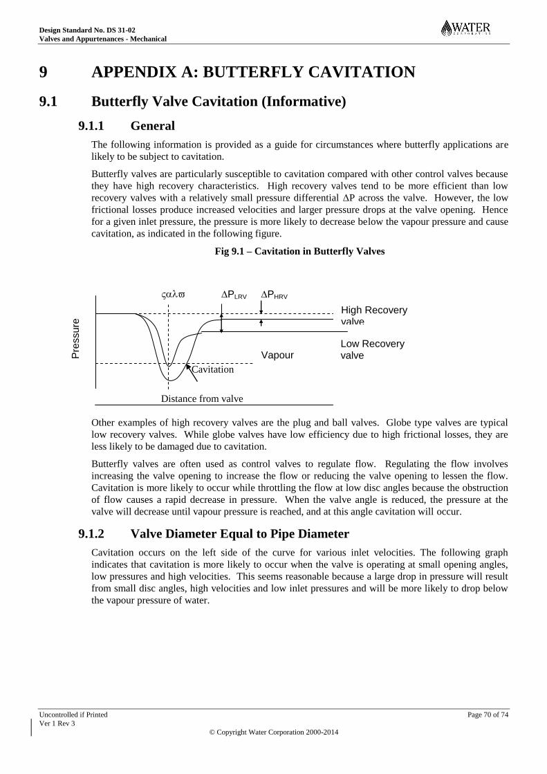
Design Standard No. DS 31-02
Valves and Appurtenances - Mechanical
Uncontrolled if Printed Page 70 of 74
Ver 1 Rev 3
© Copyright Water Corporation 2000-2014
Pre
ssure
9 APPENDIX A: BUTTERFLY CAVITATION
9.1 Butterfly Valve Cavitation (Informative)
9.1.1 General
The following information is provided as a guide for circumstances where butterfly applications are
likely to be subject to cavitation.
Butterfly valves are particularly susceptible to cavitation compared with other control valves because
they have high recovery characteristics. High recovery valves tend to be more efficient than low
recovery valves with a relatively small pressure differential ΔP across the valve. However, the low
frictional losses produce increased velocities and larger pressure drops at the valve opening. Hence
for a given inlet pressure, the pressure is more likely to decrease below the vapour pressure and cause
cavitation, as indicated in the following figure.
Fig 9.1 – Cavitation in Butterfly Valves
Cavitation
Distance from valve
Other examples of high recovery valves are the plug and ball valves. Globe type valves are typical
low recovery valves. While globe valves have low efficiency due to high frictional losses, they are
less likely to be damaged due to cavitation.
Butterfly valves are often used as control valves to regulate flow. Regulating the flow involves
increasing the valve opening to increase the flow or reducing the valve opening to lessen the flow.
Cavitation is more likely to occur while throttling the flow at low disc angles because the obstruction
of flow causes a rapid decrease in pressure. When the valve angle is reduced, the pressure at the
valve will decrease until vapour pressure is reached, and at this angle cavitation will occur.
9.1.2 Valve Diameter Equal to Pipe Diameter
Cavitation occurs on the left side of the curve for various inlet velocities. The following graph
indicates that cavitation is more likely to occur when the valve is operating at small opening angles,
low pressures and high velocities. This seems reasonable because a large drop in pressure will result
from small disc angles, high velocities and low inlet pressures and will be more likely to drop below
the vapour pressure of water.
High Recovery valve
Low Recovery valve
PHRV PLRV
Vapour Pressure
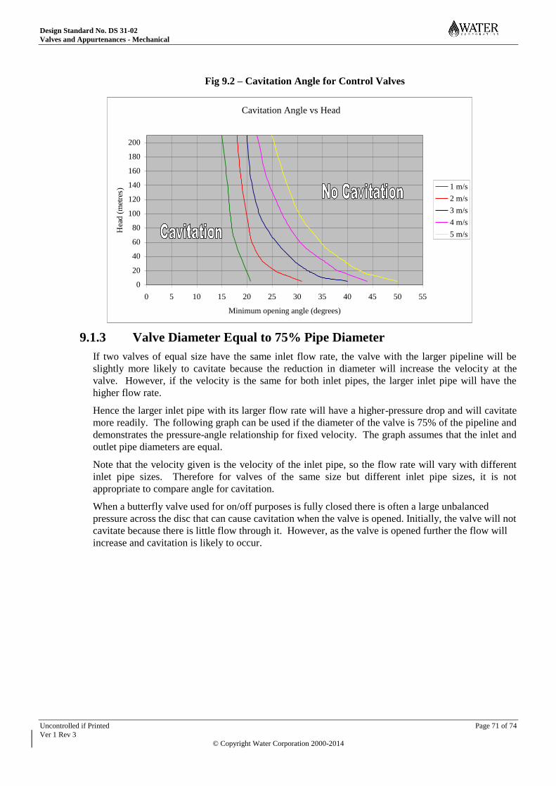
Design Standard No. DS 31-02
Valves and Appurtenances - Mechanical
Uncontrolled if Printed Page 71 of 74
Ver 1 Rev 3
© Copyright Water Corporation 2000-2014
Fig 9.2 – Cavitation Angle for Control Valves
9.1.3 Valve Diameter Equal to 75% Pipe Diameter
If two valves of equal size have the same inlet flow rate, the valve with the larger pipeline will be
slightly more likely to cavitate because the reduction in diameter will increase the velocity at the
valve. However, if the velocity is the same for both inlet pipes, the larger inlet pipe will have the
higher flow rate.
Hence the larger inlet pipe with its larger flow rate will have a higher-pressure drop and will cavitate
more readily. The following graph can be used if the diameter of the valve is 75% of the pipeline and
demonstrates the pressure-angle relationship for fixed velocity. The graph assumes that the inlet and
outlet pipe diameters are equal.
Note that the velocity given is the velocity of the inlet pipe, so the flow rate will vary with different
inlet pipe sizes. Therefore for valves of the same size but different inlet pipe sizes, it is not
appropriate to compare angle for cavitation.
When a butterfly valve used for on/off purposes is fully closed there is often a large unbalanced
pressure across the disc that can cause cavitation when the valve is opened. Initially, the valve will not
cavitate because there is little flow through it. However, as the valve is opened further the flow will
increase and cavitation is likely to occur.
Cavitation Angle vs Head
0
20
40
60
80
100
120
140
160
180
200
0 5 10 15 20 25 30 35 40 45 50 55
Minimum opening angle (degrees)
Hea
d (
met
res)
1 m/s
2 m/s
3 m/s
4 m/s
5 m/s

Design Standard No. DS 31-02
Valves and Appurtenances - Mechanical
Uncontrolled if Printed Page 72 of 74
Ver 1 Rev 3
© Copyright Water Corporation 2000-2014
Figure 9.3 – Cavitation Angle for 75% Control Valves
9.1.4 Maximum Opening Angle and Differential Head Relationship
The graph below indicates that there is little difference between a valve that is 75% of the pipe size
compared with a valve that is the same size as the pipe.
As they are so similar it would be sufficient to use one graph to describe both situations. Thus when
choosing valve sizes slightly smaller valves should be chosen because they are less expensive and do
not change the flow significantly.
The graphs can be used in practice to estimate the valve angle that will prevent cavitation. However it
is recommended that the curve for incipient cavitation is used, allowing for a further 2 or 3 degrees
opening before damaging cavitation occurs.
Cavitation Angle vs Head for 75% valve
0
20
40
60
80
100
120
140
160
180
200
0 5 10 15 20 25 30 35 40 45 50 55 60 65 70 75
Minimum opening angle (degrees)
Head (
metr
es) 1 m/s
2 m/s
3 m/s
4 m/s
5 m/s
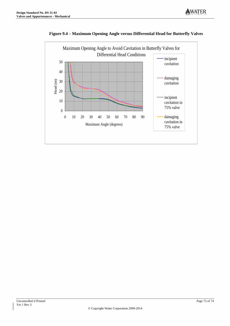
Design Standard No. DS 31-02
Valves and Appurtenances - Mechanical
Uncontrolled if Printed Page 73 of 74
Ver 1 Rev 3
© Copyright Water Corporation 2000-2014
Figure 9.4 – Maximum Opening Angle versus Differential Head for Butterfly Valves
Maximum Opening Angle to Avoid Cavitation in Butterfly Valves for
Differential Head Conditions
0
10
20
30
40
50
0 10 20 30 40 50 60 70 80 90
Maximum Angle (degrees)
Head
(m
)incipient
cavitation
damaging
cavitation
incipient
cavitation in
75% valve
damaging
cavitation in
75% valve
Design Standard No. DS 31-02
Valves and Appurtenances - Mechanical
Uncontrolled if Printed Page 74 of 74
Ver 1 Rev 3
© Copyright Water Corporation 2000-2014
END OF DOCUMENT