part 2: determination of accuracy and repeatability of...
TRANSCRIPT

Reference numberISO 230-2:2006(E)
© ISO 2006
INTERNATIONAL STANDARD
ISO230-2
Third edition2006-03-15
Test code for machine tools — Part 2: Determination of accuracy and repeatability of positioning numerically controlled axes
Code d'essai des machines-outils —
Partie 2: Détermination de l'exactitude et de la répétabilité de positionnement des axes en commande numérique
Copyright International Organization for Standardization Provided by IHS under license with ISO
Not for ResaleNo reproduction or networking permitted without license from IHS
--`,,```,,,,````-`-`,,`,,`,`,,`---

ISO 230-2:2006(E)
PDF disclaimer This PDF file may contain embedded typefaces. In accordance with Adobe's licensing policy, this file may be printed or viewed but shall not be edited unless the typefaces which are embedded are licensed to and installed on the computer performing the editing. In downloading this file, parties accept therein the responsibility of not infringing Adobe's licensing policy. The ISO Central Secretariat accepts no liability in this area.
Adobe is a trademark of Adobe Systems Incorporated.
Details of the software products used to create this PDF file can be found in the General Info relative to the file; the PDF-creation parameters were optimized for printing. Every care has been taken to ensure that the file is suitable for use by ISO member bodies. In the unlikely event that a problem relating to it is found, please inform the Central Secretariat at the address given below.
© ISO 2006 All rights reserved. Unless otherwise specified, no part of this publication may be reproduced or utilized in any form or by any means, electronic or mechanical, including photocopying and microfilm, without permission in writing from either ISO at the address below or ISO's member body in the country of the requester.
ISO copyright office Case postale 56 • CH-1211 Geneva 20 Tel. + 41 22 749 01 11 Fax + 41 22 749 09 47 E-mail [email protected] Web www.iso.org
Published in Switzerland
ii © ISO 2006 – All rights reserved
Copyright International Organization for Standardization Provided by IHS under license with ISO
Not for ResaleNo reproduction or networking permitted without license from IHS
--`,,```,,,,````-`-`,,`,,`,`,,`---

ISO 230-2:2006(E)
© ISO 2006 – All rights reserved iii
Contents Page
Foreword............................................................................................................................................................ iv Introduction ....................................................................................................................................................... vi 1 Scope ......................................................................................................................................................1 2 Terms and definitions ...........................................................................................................................1 3 Test conditions ......................................................................................................................................5 3.1 Environment ...........................................................................................................................................5 3.2 Machine to be tested .............................................................................................................................6 3.3 Warm-up .................................................................................................................................................6 4 Test programme.....................................................................................................................................6 4.1 Mode of operation..................................................................................................................................6 4.2 Selection of target position ..................................................................................................................6 4.3 Measurements........................................................................................................................................7 5 Evaluation of the results .......................................................................................................................8 5.1 Linear axes up to 2 000 mm and rotary axes up to 360°....................................................................8 5.2 Linear axes exceeding 2 000 mm and rotary axes exceeding 360° ..................................................9 6 Points to be agreed between supplier/manufacturer and user.........................................................9 7 Presentation of results..........................................................................................................................9 7.1 Method of presentation .........................................................................................................................9 7.2 Parameters ...........................................................................................................................................10 Annex A (informative) Measurement uncertainty estimation for linear positioning measurement —
Simplified method................................................................................................................................15 Annex B (informative) Step cycle ....................................................................................................................31 Bibliography ......................................................................................................................................................32
Copyright International Organization for Standardization Provided by IHS under license with ISO
Not for ResaleNo reproduction or networking permitted without license from IHS
--`,,```,,,,````-`-`,,`,,`,`,,`---

ISO 230-2:2006(E)
iv © ISO 2006 – All rights reserved
Foreword
ISO (the International Organization for Standardization) is a worldwide federation of national standards bodies (ISO member bodies). The work of preparing International Standards is normally carried out through ISO technical committees. Each member body interested in a subject for which a technical committee has been established has the right to be represented on that committee. International organizations, governmental and non-governmental, in liaison with ISO, also take part in the work. ISO collaborates closely with the International Electrotechnical Commission (IEC) on all matters of electrotechnical standardization.
International Standards are drafted in accordance with the rules given in the ISO/IEC Directives, Part 2.
The main task of technical committees is to prepare International Standards. Draft International Standards adopted by the technical committees are circulated to the member bodies for voting. Publication as an International Standard requires approval by at least 75 % of the member bodies casting a vote.
Attention is drawn to the possibility that some of the elements of this document may be the subject of patent rights. ISO shall not be held responsible for identifying any or all such patent rights.
ISO 230-2 was prepared by Technical Committee ISO/TC 39, Machine tools, Subcommittee SC 2, Test conditions for metal cutting machine tools.
This third edition cancels and replaces the second edition (ISO 230-2:1997), which has been technically revised. In particular, the following modifications have been made:
⎯ a measurement uncertainty statement requirement has been added to the presentation of results (Clause 7);
⎯ determination of measurement uncertainty is included as a new Annex A;
⎯ some editorial changes have been made in the body of the document, mainly to the Introduction;
⎯ ISO 230-2:1997/Cor 1:1999 has been incorporated as 2.23.
ISO 230 consists of the following parts, under the general title Test code for machine tools:
⎯ Part 1: Geometric accuracy of machines operating under no-load or finishing conditions
⎯ Part 2: Determination of accuracy and repeatability of positioning numerically controlled axes
⎯ Part 3: Determination of thermal effects
⎯ Part 4: Circular tests for numerically controlled machine tools
⎯ Part 5: Determination of the noise emission
⎯ Part 6: Determination of positioning accuracy on body and face diagonals (Diagonal displacement tests)
⎯ Part 7: Geometric Accuracy of axes of rotation
⎯ Part 9: Estimation of measurement uncertainty for machine tool tests according to series 230, basic equations [Technical Report]
Copyright International Organization for Standardization Provided by IHS under license with ISO
Not for ResaleNo reproduction or networking permitted without license from IHS
--`,,```,,,,````-`-`,,`,,`,`,,`---

ISO 230-2:2006(E)
© ISO 2006 – All rights reserved v
The following parts are under preparation:
⎯ Part 8: Determination of vibration levels [Technical Report]
Copyright International Organization for Standardization Provided by IHS under license with ISO
Not for ResaleNo reproduction or networking permitted without license from IHS
--`,,```,,,,````-`-`,,`,,`,`,,`---

ISO 230-2:2006(E)
vi © ISO 2006 – All rights reserved
Introduction
The purpose of ISO 230 is to standardize methods for testing the accuracy of machine tools, excluding portable power tools.
This part of ISO 230 specifies test procedures used to determine the accuracy and repeatability of positioning numerically controlled axes. The tests are designed to measure the relative displacements between the component that holds the tool and the component that holds the workpiece.
Since measurement uncertainty needs to be stated with the measurement results, a description of the estimation of the measurement uncertainty for the determination of the accuracy and repeatability of positioning has been added as Annex A.
It is believed that, with this addition, the relevant contributors to the measurement uncertainty are able to be recognized more easily and reduced more efficiently.
The supplier/manufacturer should provide thermal specifications for the environment in which the machine can be expected to perform with the specified accuracy. The machine user is responsible for providing a suitable test environment by meeting the supplier/manufacturer’s thermal guidelines or otherwise accepting reduced performance. An example of environmental thermal guidelines is given in ISO 230-3:— [1], Annex C.
A relaxation of accuracy expectations is required if the thermal environment causes excessive uncertainty or variation in the machine tool performance and does not meet the supplier/manufacturer’s thermal guidelines. If the machine does not meet performance specifications, the analysis of the uncertainty due to the compensation of the machine tool temperature, given in A.2.4 of this part of ISO 230, and the uncertainty due to the environmental variation error, given in A.2.5, can help in identifying sources of problems.
Copyright International Organization for Standardization Provided by IHS under license with ISO
Not for ResaleNo reproduction or networking permitted without license from IHS
--`,,```,,,,````-`-`,,`,,`,`,,`---

INTERNATIONAL STANDARD ISO 230-2:2006(E)
© ISO 2006 – All rights reserved 1
Test code for machine tools —
Part 2: Determination of accuracy and repeatability of positioning numerically controlled axes
1 Scope
This part of ISO 230 specifies methods for testing and evaluating the accuracy and repeatability of the positioning of numerically controlled machine tool axes by direct measurement of individual axes on the machine. These methods apply equally to linear and rotary axes.
When several axes are simultaneously under test, the methods do not apply.
This part of ISO 230 can be used for type testing, acceptance tests, comparison testing, periodic verification, machine compensation, etc.
The methods involve repeat measurements at each position. The related parameters of the test are defined and calculated. Their uncertainties are estimated as described in ISO/TR 230-9:2005, Annex C [2].
Annex A presents the estimation of the measurement uncertainty.
Annex B describes the application of an optional test cycle — the step cycle. The results from this cycle are not to be used either in the technical literature with reference to this part of ISO 230, nor for acceptance purposes, except under special written agreements between supplier/manufacturer and user. Correct reference to this part of ISO 230 for machine acceptance always refers to the standard test cycle.
2 Terms and definitions
For the purposes of this document, the following definitions and symbols apply.
2.1 axis travel maximum travel, linear or rotary, over which the moving component can move under numerical control
NOTE For rotary axes exceeding 360°, there may not be a clearly defined maximum length of travel.
2.2 measurement travel part of the axis travel, used for data capture, selected so that the first and the last target positions can be approached bi-directionally
See Figure 1.
2.3 target position Pi (i = 1 to m) position to which the moving part is programmed to move
NOTE The subscript i identifies the particular position among other selected target positions along or around the axis.
Copyright International Organization for Standardization Provided by IHS under license with ISO
Not for ResaleNo reproduction or networking permitted without license from IHS
--`,,```,,,,````-`-`,,`,,`,`,,`---

ISO 230-2:2006(E)
2 © ISO 2006 – All rights reserved
2.4 actual position Pij (i = 1 to m; j = 1 to n) measured position reached by the moving part on the j th approach to the i th target position.
2.5 deviation of position; positional deviation xij actual position reached by the moving part minus the target position
xij = Pij − Pi
2.6 unidirectional refers to a series of measurements in which the approach to a target position is always made in the same direction along or around the axis
NOTE The symbol ↑ signifies a parameter derived from a measurement made after an approach in the positive direction, and ↓ one in the negative direction, e.g. xij↑ or xij↓.
2.7 bi-directional refers to a parameter derived from a series of measurements in which the approach to a target position is made in either direction along or around the axis
2.8 expanded uncertainty quantity defining an interval about the result of a measurement that can be expected to encompass a large fraction of the distribution of values
2.9 coverage factor numerical factor used as a multiplier of the combined standard uncertainty in order to obtain an expanded uncertainty.
2.10 mean unidirectional positional deviation at a position
ix ↑ or ix ↓ arithmetic mean of the positional deviations obtained by a series of n unidirectional approaches to a position Pi.
1
1 n
i ijj
x xn =
↑= ↑∑
and
1
1 n
i ijj
x xn =
↓= ↓∑
2.11 mean bi-directional positional deviation at a position
ix arithmetic mean of the mean unidirectional positional deviations ix ↑ and ix ↓ obtained from the two directions of approach at a position Pi
2i i
ix x
x↑ + ↓
=
Copyright International Organization for Standardization Provided by IHS under license with ISO
Not for ResaleNo reproduction or networking permitted without license from IHS
--`,,```,,,,````-`-`,,`,,`,`,,`---

ISO 230-2:2006(E)
© ISO 2006 – All rights reserved 3
2.12 reversal value at a position Bi value of the difference between the mean unidirectional positional deviations obtained from the two directions of approach at a position Pi
i i iB x x= ↑ − ↓
2.13 reversal value of an axis B maximum of the absolute reversal values ⎜Bi⎜ at all target positions along or around the axis
max. iB B⎡ ⎤= ⎣ ⎦
2.14 mean reversal value of an axis B arithmetic mean of the reversal values Bi at all target positions along or around the axis
1
1 m
ii
B Bm =
= ∑
2.15 estimator for the unidirectional axis repeatability of positioning at a position si↑ or si↓ estimator of the standard uncertainty of the positional deviations obtained by a series of n unidirectional approaches at a position Pi.
( )2
1
11
n
i ij ij
s x xn =
↑= ↑ − ↑− ∑
and
( )2
1
11
n
i ij ij
s x xn =
↓= ↓ − ↓− ∑
2.16 unidirectional repeatability of positioning at a position
iR ↑ or iR ↓ range derived from the estimator for the unidirectional axis repeatability of positioning at a position Pi using a coverage factor of 2
4i iR s↑= ↑
and
4i iR s↓= ↓
Copyright International Organization for Standardization Provided by IHS under license with ISO
Not for ResaleNo reproduction or networking permitted without license from IHS
--`,,```,,,,````-`-`,,`,,`,`,,`---

ISO 230-2:2006(E)
4 © ISO 2006 – All rights reserved
2.17 bi-directional repeatability of positioning at a position Ri
max. 2 2 ; ;i i i i i iR s s B R R⎡ ⎤= ↑ + ↓ + ↑ ↓⎣ ⎦
2.18 unidirectional repeatability of positioning R↑ or R↓ maximum value of the repeatability of positioning at any position Pi along or around the axis
max. iR R⎡ ⎤↑= ↑⎣ ⎦
max. iR R⎡ ⎤↓= ↓⎣ ⎦
2.19 bi-directional repeatability of positioning of an axis R maximum value of the repeatability of positioning at any position Pi along or around the axis
max. iR R= ⎡ ⎤⎣ ⎦
2.20 unidirectional systematic positional deviation of an axis E↑ or E↓ The difference between the algebraic maximum and minimum of the mean unidirectional positional deviations for one approach direction ix ↑ or ix ↓ at any position Pi along or around the axis.
max. min.i iE x x⎡ ⎤ ⎡ ⎤↑= ↑ − ↑⎣ ⎦ ⎣ ⎦
and
max. min.i iE x x⎡ ⎤ ⎡ ⎤↓= ↓ − ↓⎣ ⎦ ⎣ ⎦
2.21 bi-directional systematic positional deviation of an axis E difference between the algebraic maximum and minimum of the mean unidirectional positional deviations for both approach directions ix ↑ and ix ↓ at any position Pi along or around the axis
max. ; min. ;i i i iE x x x x⎡ ⎤ ⎡ ⎤= ↑ ↓ − ↑ ↓⎣ ⎦ ⎣ ⎦
2.22 mean bi-directional positional deviation of an axis M difference between the algebraic maximum and minimum of the mean bi-directional positional deviations ix at any position Pi along or around the axis
max. min.i iM x x= −⎡ ⎤ ⎡ ⎤⎣ ⎦ ⎣ ⎦
Copyright International Organization for Standardization Provided by IHS under license with ISO
Not for ResaleNo reproduction or networking permitted without license from IHS
--`,,```,,,,````-`-`,,`,,`,`,,`---

ISO 230-2:2006(E)
© ISO 2006 – All rights reserved 5
2.23 unidirectional accuracy of positioning of an axis A↑ or A↓ range derived from the combination of the unidirectional systematic deviations and the estimator for axis repeatability of unidirectional positioning using a coverage factor of 2
max. 2 min. 2i i i iA x s x s⎡ ⎤ ⎡ ⎤↑= ↑ + ↑ − ↑ − ↑⎣ ⎦ ⎣ ⎦
and
max. 2 min. 2i i i iA x s x s⎡ ⎤ ⎡ ⎤↓= ↓ + ↓ − ↓ − ↓⎣ ⎦ ⎣ ⎦
2.24 bi-directional accuracy of positioning of an axis A range derived from the combination of the bi-directional systematic deviations and the estimator for axis repeatability of bi-directional positioning using a coverage factor of 2
max. 2 ; 2 min. 2 ; 2i i i i i i i iA x s x s x s x s⎡ ⎤ ⎡ ⎤= ↑ + ↑ ↓ + ↓ − ↑ − ↑ ↓ − ↓⎣ ⎦ ⎣ ⎦
3 Test conditions
3.1 Environment
It is recommended that the supplier/manufacturer offer guidelines regarding the kind of thermal environment acceptable for the machine to perform with the specified accuracy.
Such general guidelines could contain, for example, a specification on the mean room temperature, maximum amplitude and frequency range of deviations from this mean temperature, and environmental thermal gradients. It shall be the responsibility of the user to provide an acceptable thermal environment for the operation and the performance testing of the machine tool at the installation site. However, if the user follows the guidelines provided by the machine supplier/manufacturer, the responsibility for machine performance according to the specifications reverts to the machine supplier/manufacturer.
Ideally, all dimensional measurements are made when both the measuring instrument and the measured object are soaked in an environment at a temperature of 20 °C. If the measurements are taken at temperatures other than 20 °C, then correction for nominal differential expansion (NDE) between the axis positioning system or the workpiece/tool holding part of the machine tool and the test equipment shall be applied to yield results corrected to 20 °C. This condition might require temperature measurement of the representative part of the machine as well as the test equipment and a mathematical correction with the relevant thermal expansion coefficients. The NDE correction might also be achieved automatically, if the representative part of the machine tool and the test equipment have the same temperature and the same thermal expansion coefficient.
It should be noted, however, that any temperature departure from 20 °C can cause an additional uncertainty related to the uncertainty in the effective expansion coefficient(s) used for compensation. A typical minimum range value for the resulting uncertainty is 2 µm/(m⋅°C) (see annexes A and C). Therefore, the actual temperatures shall be stated in the test report.
The machine and, if relevant, the measuring instruments shall have been in the test environment long enough (preferably overnight) to have reached a thermally stable condition before testing. They shall be protected from draughts and external radiation such as sunlight, overhead heaters, etc.
For 12 h before the measurements and during them, the environmental temperature gradient in degrees per hour shall be within limits agreed between supplier/manufacturer and user.
Copyright International Organization for Standardization Provided by IHS under license with ISO
Not for ResaleNo reproduction or networking permitted without license from IHS
--`,,```,,,,````-`-`,,`,,`,`,,`---
ISO 230-2:2006(E)
6 © ISO 2006 – All rights reserved
3.2 Machine to be tested
The machine shall be completely assembled and fully operational. If necessary, levelling operations and geometric alignment tests shall be completed satisfactorily before starting the accuracy and repeatability tests.
If built-in compensation routines are used during the test cycle, this should be stated in the test report.
All tests shall be carried out with the machine in the unloaded condition, i.e. without a workpiece.
The positions of the axis slides or moving components on the axes which are not under test shall be stated in the test report.
3.3 Warm-up
When testing of the machine under normal operating conditions, the tests shall be immediately preceded by an appropriate warm-up operation as specified by the supplier/manufacturer of the machine, or agreed between supplier/manufacturer and user.
If no conditions are specified, the warm-up operations may take the form of a “preliminary dummy run” of the accuracy test without gathering data; or the preliminary movements may be restricted to those necessary for setting up the measuring instruments. The warm-up operation chosen shall be stated in the test report.
Non-stable thermal conditions are recognized as an ordered progression of deviations between successive approaches to any particular target position. These trends should be minimized through the warm-up operation.
4 Test programme
4.1 Mode of operation
The machine shall be programmed to move the moving part along or around the axis under test, and to position it at a series of target positions where it will remain at rest long enough for the actual position to be reached, measured and recorded. The machine shall be programmed to move between the target positions at an agreed feed rate.
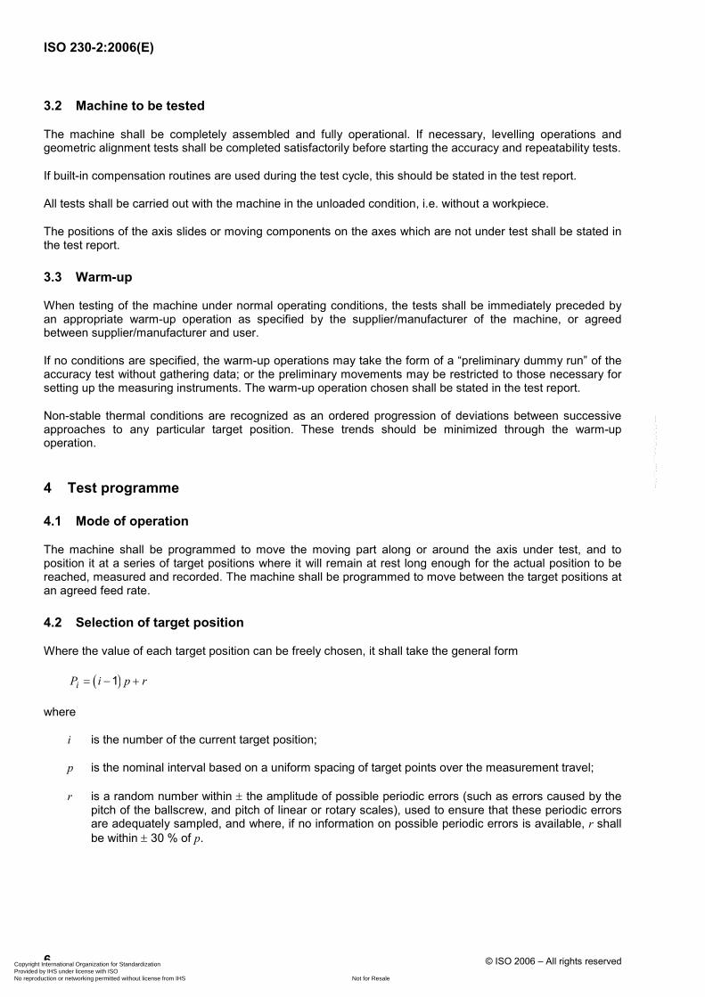
4.2 Selection of target position
Where the value of each target position can be freely chosen, it shall take the general form
( )1iP i p r= − +
where
i is the number of the current target position;
p is the nominal interval based on a uniform spacing of target points over the measurement travel;
r is a random number within ± the amplitude of possible periodic errors (such as errors caused by the pitch of the ballscrew, and pitch of linear or rotary scales), used to ensure that these periodic errors are adequately sampled, and where, if no information on possible periodic errors is available, r shall be within ± 30 % of p.
Copyright International Organization for Standardization Provided by IHS under license with ISO
Not for ResaleNo reproduction or networking permitted without license from IHS
--`,,```,,,,````-`-`,,`,,`,`,,`---

ISO 230-2:2006(E)
© ISO 2006 – All rights reserved 7
4.3 Measurements
4.3.1 Set-up and instrumentation
The measurement setup is designed to measure the relative displacements between the component that holds the tool and the component that holds the workpiece in the direction of motion of the axis under test.
The position of the measuring instrument shall be recorded on the test sheet.
If mathematical NDE correction is applied, the position of the temperature sensor(s) on the machine components, the expansion coefficients used for NDE correction and the type of compensation routine shall be stated on the test sheet.
4.3.2 Tests for linear axes up to 2 000mm
On machine axes of travel up to 2 000 mm, a minimum of five target positions per metre and an overall minimum of five target positions shall be selected in accordance with 4.2.
Measurements shall be made at all the target positions according to the standard test cycle (see Figure 1). Each target position shall be attained five times in each direction.
The position of changing direction should be chosen to allow for normal behaviour of the machine (to achieve the agreed feed rate).
a Position i(m = 8). b Cycle j(n = 5). c Target points.
Figure 1 — Standard test cycle
Copyright International Organization for Standardization Provided by IHS under license with ISO
Not for ResaleNo reproduction or networking permitted without license from IHS
--`,,```,,,,````-`-`,,`,,`,`,,`---

ISO 230-2:2006(E)
8 © ISO 2006 – All rights reserved
4.3.3 Tests for linear axes exceeding 2 000 mm
For axes longer than 2 000 mm, the whole measurement travel of the axis shall be tested by making one unidirectional approach in each direction to target positions selected according to 4.2 with an average interval length, p, of 250 mm. Where the measuring transducer consists of several segments, additional target points could have to be selected to ensure that each segment has at least one target position.
The test specified in 4.3.2 shall be made over a length of 2 000 mm in the normal working area as agreed between supplier/manufacturer and user.
4.3.4 Tests for rotary axes up to 360˚
Tests shall be made at the target positions given in Table 1. The principal positions 0°, 90°, 180° and 270° should be included when available along with other target positions in accordance with 4.2. Each target position shall be attained five times in each direction.
Table 1 — Target positions for rotary axes
Measurement travel Minimum number of target positions
u 90° 3
> 90° and u 180° 5
> 180° 8
4.3.5 Tests for rotary axes exceeding 360°
For axes exceeding 360°, the total measurement travel of the axis up to 1 800° (five revolutions) shall be tested by making one unidirectional approach in each direction with a minimum of eight target points per revolution.
The test specified in 4.3.4 shall be made over an angle of 360° in the normal working area as agreed between supplier/manufacturer and user.
5 Evaluation of the results
5.1 Linear axes up to 2 000 mm and rotary axes up to 360°
For each target position Pi and for five approaches (n = 5) in each direction, the parameters defined in Clause 2 are evaluated. Furthermore, the deviation boundaries
2 and 2i i i ix s x s↑ + ↑ ↑ − ↑
and
2 and 2i i i ix s x s↓ + ↓ ↓ − ↓
are calculated.
Copyright International Organization for Standardization Provided by IHS under license with ISO
Not for ResaleNo reproduction or networking permitted without license from IHS
--`,,```,,,,````-`-`,,`,,`,`,,`---

ISO 230-2:2006(E)
© ISO 2006 – All rights reserved 9
5.2 Linear axes exceeding 2 000 mm and rotary axes exceeding 360°
For each target position and for one approach (n = 1) in each direction the applicable parameters defined in Clause 2 are evaluated. Estimators for the unidirectional axis repeatability (2.15), repeatabilities (2.16, 2.17, 2.18 and 2.19) and accuracies (2.23 and 2.24) are not applicable. The evaluation of results in 5.1 over a length of 2 000 mm or 360° shall also be provided as agreed between supplier/manufacturer and user.
6 Points to be agreed between supplier/manufacturer and user
The points to be agreed between the supplier/manufacturer and the user are as follows:
a) the maximum rate of environmental temperature gradient in degrees per hour for 12 h before and during the measurements (see 3.1);
b) the location of the measuring instrument and the positions of the temperature sensors if relevant (see 4.3.1);
c) the warm-up operation to precede testing the machine (see 3.3);
d) the feed rate between target positions;
e) the position of the 2 000 mm or 360o measurement travel to be regarded as the normal working area (see 4.3.3 or 4.3.5) if relevant;
f) position of the slides or moving components which are not under test;
g) dwell time at each target position;
h) location of first and last target positions.
7 Presentation of results
7.1 Method of presentation
The preferred method of presentation of the results is a graphical one with the following list of items recorded on the test report in order to identify the measurement setup.
⎯ position of the measuring instrument;
⎯ if mathematical NDE correction is applied
⎯ coefficients(s) of thermal expansion used for NDE correction,
⎯ position of the temperature sensor(s) used for NDE correction on the machine components and on the test equipment,
⎯ temperatures of sensors for NDE correction on the machine components representing machine scale or workpiece/tool holding part of the machine and temperatures of sensors on the test equipment, at the start and end of the test,
⎯ type of compensation routine (e.g. frequency of updating compensation parameters);
⎯ date of test;
⎯ machine name, type (horizontal spindle or vertical spindle) and its coordinate axes travels;
Copyright International Organization for Standardization Provided by IHS under license with ISO
Not for ResaleNo reproduction or networking permitted without license from IHS
--`,,```,,,,````-`-`,,`,,`,`,,`---

ISO 230-2:2006(E)
10 © ISO 2006 – All rights reserved
⎯ list of the test equipment used, including supplier/manufacturer's name, type and serial number of the components (laser head, optics, temperature sensors, etc.);
⎯ type of machine scale used for positioning of axis and its coefficient of thermal expansion, obtained from machine tool manufacturer/supplier (e.g. ball screw/rotary resolver system, linear scale system);
⎯ name of axis under test
⎯ for linear axis, the location of its measurement line relative to the axes not under test (this location is determined by the offset to tool reference, offset to workpiece reference and the locations of axes not under test, with both of these offsets being determined by the specific machine configuration),
⎯ for rotary axis, a description of nominal location (position and orientation) of the axis;
⎯ feed rate and dwell time at each target position, list of nominal target positions;
⎯ warm-up operation to precede testing the machine (number of cycles or idling time and feed rate);
⎯ if relevant, air temperature, air pressure and humidity near the laser beam at the start and end of the test;
⎯ whether or not built-in compensation routines were used during the test cycle;
⎯ use of air or oil shower, when applied;
⎯ number of approaches (n = 5 or n = 1);
⎯ contributors and parameters used for estimation of measurement uncertainty.
7.2 Parameters
7.2.1 General
The following parameters shall be specified numerically. A summary of results using the parameters denoted with an asterisk followed by a parenthesis, may provide a basis for machine acceptance. A presentation is shown in Figures 2 and 3 of the results given in Table 2.
Each parameter should be given together with the measurement uncertainty U with a coverage factor of 2, U(k = 2). The minimum requirements for information regarding the measurement uncertainty U are
⎯ the parameters for the uncertainty due to the measuring device,
⎯ the parameters for the uncertainty due to the compensation of the machine tool temperature,
⎯ the parameters for the uncertainty due to the environmental temperature variation error, and
⎯ the parameters for the uncertainty due to the misalignment of the measuring device, if relevant.
NOTE For linear axes, Annex A shows a simplified method for the estimation of the measurement uncertainty, including examples. More detailed information and formulae are included in of ISO/TR 230-9:2005 Annex C.
Copyright International Organization for Standardization Provided by IHS under license with ISO
Not for ResaleNo reproduction or networking permitted without license from IHS
--`,,```,,,,````-`-`,,`,,`,`,,`---

ISO 230-2:2006(E)
© ISO 2006 – All rights reserved 11
7.2.2 Tests for linear axes up to 2 000 mm and rotary axes up to 360°
⎯ Bi-directional accuracy of positioning of an axis*) A
⎯ Unidirectional accuracy of positioning of an axis*) A↑ and A↓
⎯ Bi-directional systematic positional deviation of an axis*) E
⎯ Unidirectional systematic positional deviation of an axis E↑ and E↓
⎯ Range of the mean bi-directional positional deviation of an axis*) M
⎯ Bi-directional repeatability of positioning of an axis R
⎯ Unidirectional repeatability of positioning of an axis*) R↑ and R↓
⎯ Reversal value of an axis*) B
⎯ Mean reversal value of an axis B
7.2.3 Tests for linear axes exceeding 2 000 mm and rotary axes exceeding 360°
⎯ Bi-directional systematic positional deviation of an axis*) E
⎯ Unidirectional systematic positional deviation of an axis E↑ and E↓
⎯ Range of the mean bi-directional positional deviation of an axis*) M
⎯ Reversal value of an axis*) B
⎯ Mean reversal value of an axis B
Copyright International Organization for Standardization Provided by IHS under license with ISO
Not for ResaleNo reproduction or networking permitted without license from IHS
--`,,```,,,,````-`-`,,`,,`,`,,`---

ISO 230-2:2006(E)
12 © ISO 2006 – All rights reserved
Tabl
e 2
— T
ypic
al te
st re
sults
(tes
t for
line
ar a
xis
up to
2 0
00 m
m)
i 1
2 3
4 5
6 7
8 9
10
11
Targ
et p
ositi
on P
i (m
m)
6,71
1 17
5,07
7 35
3,83
4 52
5,66
8 70
4,17
5 88
1,86
8 10
55,8
90
1234
,304
14
08,4
62
1580
,269
17
50,9
20
App
roac
h di
rect
ion
↓ ↑
↓ ↑
↓ ↑
↓ ↑
↓ ↑
↓ ↑
↓ ↑
↓ ↑
↓ ↑
↓ ↑
↓ ↑
j = 1
2,
3 −1
,2
3,6
−0,5
3,5
0,2
3,0
−0,6
1,7
−1,9
0,4
−3,0
−0
,4
−3,7
−0
,2
−3,7
0,
2 −3
,5
0,3
−3,2
−0
,1
−3,6
2
2,1
−1,7
3,
5 −0
,93,
3−0
,62,
7−1
,21,
5 −2
,30,
2 −3
,5
−0,7
−4
,3
−0,6
−4
,4
-0,2
−4,3
−0
,1
−3,8
−0
,6
−4,0
3
1,9
−1,9
3,
1 −1
,13,
0−0
,72,
4−1
,31,
0 −2
,9−0
,2−3
,7
−1,0
−4
,6
−1,0
−5
,1
-1,0
−5,0
−0
,9
−4,7
−1
,2
−4,5
4
2,8
−1,3
3,
7 −0
,23,
80,
1 3,
2−0
,31,
9 −1
,40,
9 −2
,8
0,0
−3,6
−0
,2
−3,6
0,
5 −3
,2
0,5
−2,8
0,
4 −3
,2
Posi
tiona
l de
viat
ions
(µm
)
5 2,
2 −1
,9
3,2
−0,8
3,5
−0,7
2,6
−1,3
1,1
−2,3
−0,1
−3,7
−0
,9
−4,5
−1
,1
−4,6
-0
,5−4
,5
-0,4
−4
,1
−0,9
−4
,5
Mea
n un
idire
ctio
nal
posi
tiona
l dev
iatio
n ix(µ
m)
2,3
−1,6
3,
4 −0
,73,
4−0
,32,
8−0
,91,
4 −2
,20,
2 −3
,3
−0,6
−4
,1
−0,6
−4
,3
-0,2
-4,1
-0
,1
−3,7
−0
,5
−4,0
Estim
ator
of s
tand
ard
unce
rtai
nty
s i (µm
) 0,
3 0,
3 0,
3 0,
4 0,
30,
5 0,
30,
5 0,
4 0,
6 0,
4 0,
4 0,
4 0,
5 0,
4 0,
6 0,
6 0,
7 0,
6 0,
7 0,
6 0,
6
2si (µm
) 0,
7 0,
7 0,
5 0,
7 0,
60,
9 0,
60,
9 0,
8 1,
1 0,
9 0,
8 0,
8 0,
9 0,
9 1,
3 1,
2 1,
5 1,
1 1,
5 1,
3 1,
1
ix–
2si (µm
) 1,
6 −2
,3
2,9
−1,4
2,8
−1,2
2,1
−1,9
0,7
−3,3
−0,6
−4,2
−1
,4
−5,1
−1
,5
−5,5
-1
,4−5
,6
-1,2
−5
,2
−1,8
−5
,1
ix +
2s i (µm
) 2,
9 −0
,9
3,9
0,0
4,0
0,6
3,4
0,0
2,2
−1,1
1,1
−2,5
0,
2 −3
,2
0,2
−3,0
1,
0 −2
,6
1,0
−2,2
0,
8 −2
,8
Uni
dire
ctio
nal r
epea
tabi
lity
R i = 4
s i (µm
) 1,
3 1,
3 1,
0 1,
4 1,
21,
8 1,
31,
8 1,
5 2,
2 1,
8 1,
8 1,
6 1,
8 1,
7 2,
5 2,
3 3,
0 2,
2 3,
0 2,
6 2,
3
Rev
ersa
l val
ue B
i (µ m
) −3
,9
−4,1
−3
,8
−3,7
−3
,6
−3,6
−3
,6
−3,7
−3
,9
−3,6
−3
,5
Bid
irect
iona
l rep
eata
bilit
y R i
(µm
) 5,
2 5,
3 5,
3 5,
2 5,
5 5,
3 5,
3 5,
8 6,
6 6,
2 5,
9
Mea
n bi
dire
ctio
nal p
ositi
onal
de
viat
ion
ix(µ
m)
0,3
1,4
1,5
0,9
−0,4
−1
,6
−2,4
−2
,5
−2,2
−1
,9
−2,2
Axi
s de
viat
ion
(mm
) U
nidi
rect
iona
l ↓
Uni
dire
ctio
nal ↑
B
idire
ctio
nal
Rev
ersa
l val
ue B
N
ot A
pplic
able
N
ot A
pplic
able
0,
004
± 0,
001
mm
(at
i =
2) ( k
= 2
)
Mea
n re
vers
al v
alue
B
Not
App
licab
le
Not
App
licab
le
−0,0
04
Ran
ge m
ean
bidi
rect
iona
l po
sitio
nal d
evia
tion
M
Not
App
licab
le
Not
App
licab
le
0,00
4 ±
0,00
4 m
m
(k =
2)
(0,0
01 5
− −0
,002
5)
Sys
tem
atic
pos
ition
al
devi
atio
n E
0,00
4 (=
0,0
03 4
− −0
,000
6)
0,00
4 (−
0,00
0 3 −
−0,
004
3)
0,00
8 ±
0,00
4 m
m
(k =
2)
(0,0
03 4
− −0
,004
3)
Rep
eata
bilit
y of
pos
ition
ing
R 0,
003
(at i
= 1
1)
0,00
3 (a
t i =
10)
0,
007
± 0,
002
mm
(k
= 2
)
Acc
urac
y A
0,00
6 (0
,004
0−
−0,0
01 8
) 0,
006
(0,0
006 −
−0,
005
5)
0,01
0 ±
0,00
4 m
m
(k =
2)
(0,0
04 0
− −0
,005
6)
NO
TE 1
U
ncer
tain
ty v
alue
s ar
e ac
cord
ing
to T
able
A.5
; cov
erag
e fa
ctor
, k, a
ccor
ding
to 2
.9.
NO
TE 2
Th
e va
lues
giv
en in
this
tabl
e ar
e ro
unde
d.
Copyright International Organization for Standardization Provided by IHS under license with ISO
Not for ResaleNo reproduction or networking permitted without license from IHS
--`,,```,,,,````-`-`,,`,,`,`,,`---

ISO 230-2:2006(E)
© ISO 2006 – All rights reserved 13
Date of test: YY/MM/DD
Name of inspector: Joe Smith Machine name, type and serial no.: AAA, vertical spindle machining centre, serial no.: 1111111 Measuring instrument and serial no.: laser interferometer BBB, serial no.: 1234567 Test parameters
tested axis: X type of scale: ball screw and rotary encoder NDE correction location T start (°C) T end (°C)
material sensor used for NDE correction
table, centre 21,8 22,9
coefficient of thermal expansion (used for NDE correction): 11
µm/(m °C)
compensation routine update each 20 s feed rate: 1 000 mm/min. dwell time at each target position: 5 s compensation used: reversal and leadscrew
Test location position of axes not under test: Y = 300 mm; Z = 350 mm; C = 0° offset to tool reference (X/Y/Z): 0/0/120 mm offset to workpiece reference (X/Y/Z): 0/0/30 mm
Air conditions used for compensation of laser interferometer, updated each 20 s location T start (°C) T end (°C)
air temperature: centre of work zone 20,6 20,9 air pressure: 102,4 kPa air humidity: 60 %
Key X position, mm Y deviation, mm
Figure 2 — Bi-directional accuracy and repeatability of positioning
Copyright International Organization for Standardization Provided by IHS under license with ISO
Not for ResaleNo reproduction or networking permitted without license from IHS
--`,,```,,,,````-`-`,,`,,`,`,,`---
ISO 230-2:2006(E)
14 © ISO 2006 – All rights reserved
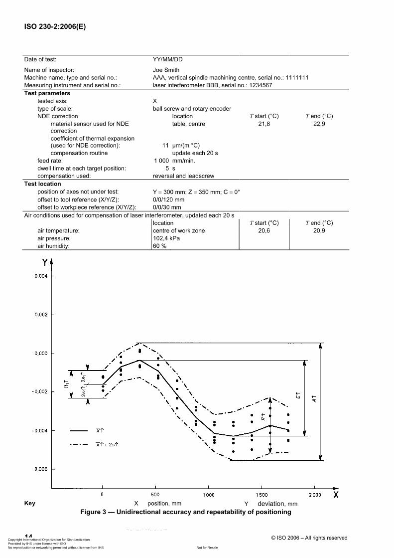
Date of test: YY/MM/DD
Name of inspector: Joe Smith Machine name, type and serial no.: AAA, vertical spindle machining centre, serial no.: 1111111 Measuring instrument and serial no.: laser interferometer BBB, serial no.: 1234567 Test parameters
tested axis: X type of scale: ball screw and rotary encoder NDE correction location T start (°C) T end (°C)
material sensor used for NDE correction
table, centre 21,8 22,9
coefficient of thermal expansion (used for NDE correction):
11
µm/(m °C)
compensation routine update each 20 s feed rate: 1 000 mm/min. dwell time at each target position: 5 s compensation used: reversal and leadscrew
Test location position of axes not under test: Y = 300 mm; Z = 350 mm; C = 0° offset to tool reference (X/Y/Z): 0/0/120 mm offset to workpiece reference (X/Y/Z): 0/0/30 mm
Air conditions used for compensation of laser interferometer, updated each 20 s location T start (°C) T end (°C)
air temperature: centre of work zone 20,6 20,9 air pressure: 102,4 kPa air humidity: 60 %
Key X position, mm Y deviation, mm
Figure 3 — Unidirectional accuracy and repeatability of positioning
Copyright International Organization for Standardization Provided by IHS under license with ISO
Not for ResaleNo reproduction or networking permitted without license from IHS
--`,,```,,,,````-`-`,,`,,`,`,,`---

ISO 230-2:2006(E)
© ISO 2006 – All rights reserved 15
Annex A (informative)
Measurement uncertainty estimation for linear positioning
measurement — Simplified method
A.1 Estimation of the measurement uncertainty
The estimation of the measurement uncertainty follows the procedures and equations of ISO/TR 230-9:2005, Annex C. The measurement uncertainties U are calculated for a coverage factor of k = 2.
A.2 Contributors to the measurement uncertainty
A.2.1 General
The contributors to the measurement uncertainty are the measuring device, the misalignment of the measuring device to the machine axis under test, the uncertainty due to the compensation of the machine tool temperature due to measurements at temperatures other than 20 °C, and environmental variation errors (EVE).
The contributors and assumptions are according to ISO/TR 230-9:2005, Annex C, except the set-up error, because it is assumed that the set up is within 10 mm of the position recorded on the test report.
A.2.2 Uncertainty due to the measuring device, UDEVICE
The equations used in this subclause are based on ISO/TR 230-9:2005, C.2.2 and Equations (C.1) and (C.2).
The use of a calibrated measuring device is recommended. If the calibration certificate states the maximum uncertainty in micrometres (µm), Equation (A.1) applies. If the calibration certificate states the uncertainty in micrometres per metre (µm/m) or in parts per million (ppm), Equation (A.2) applies.
If no calibration certificate is available and the manufacturer states an error range in micrometres per metre or parts per million, then Equation (A.3) should be used. The influence of the resolution of the measuring device is in general negligible and can be checked according to of ISO/TR 230-9:2005, C.2.2 and Equations (C.3) and (C.4).
DEVICE CALIBRATIONU U= (A.1)
where
UDEVICE is the uncertainty due to the measuring device in micrometres (µm);
UCALIBRATION is the uncertainty of calibration according to the calibration certificate in micrometres (µm) with coverage factor k = 2.
DEVICE CALIBRATIONU U L= ⋅ (A.2)
where
UDEVICE is the uncertainty due to the measuring device in micrometres (µm);
Copyright International Organization for Standardization Provided by IHS under license with ISO
Not for ResaleNo reproduction or networking permitted without license from IHS
--`,,```,,,,````-`-`,,`,,`,`,,`---

ISO 230-2:2006(E)
16 © ISO 2006 – All rights reserved
UCALIBRATION is the uncertainty of the calibration according to the calibration certificate in micrometres per metre (µm/m) or in parts per million (ppm), with coverage factor k = 2;
L measurement length in metres (m).
DEVICE DEVICE0,6U R L= ⋅ ⋅ (A.3)
where
UDEVICE is the uncertainty due to the measuring device in micrometres (µm);
RDEVICE is the error range given by manufacturer of device in parts per million (ppm) or in micrometres per metre (µm/m)
L is the measurement length in metres (m).
A.2.3 Uncertainty due to misalignment of measuring device to machine axis under test, UMISALIGNMENT
The equations used in this subclause are based on ISO/TR 230-9:2005, C.2.3 and Equation (C.5).
The measuring device has to be aligned parallel to the machine axis under test, otherwise a measurement error is observed. The influence is of second order, however, if the misalignment is larger than 1 mm and if the machine axis under test is shorter than 300 mm, this influence can become significant. Equation (A.4) and Table A.1 show the influences of a misalignment.
With optical measurement equipment such as a laser interferometer, the misalignment will be within 1 mm, if the movement of the reflected beam is as recommended by the equipment manufacturers. If the alignment is simply made in order to have sufficient return beam intensity, which is not recommended, the misalignment might be up to 4 mm.
With mechanical measurement equipment such as a linear scale, the alignment with the help of a side face will result in an misalignment of smaller than 0,5 mm.
2MISALIGNMENT
MISALIGNMENT 0,3R
UL
= ⋅ (A.4)
where
UMISALIGNMENT measurement uncertainty due to misalignment in micrometres (µm);
RMISALIGNMENT misalignment in millimetres (mm);
L measurement length in metres (m).
Copyright International Organization for Standardization Provided by IHS under license with ISO
Not for ResaleNo reproduction or networking permitted without license from IHS
--`,,```,,,,````-`-`,,`,,`,`,,`---

ISO 230-2:2006(E)
© ISO 2006 – All rights reserved 17
Table A.1 — Measurement uncertainty due to misalignment of measurement equipment UMISALIGNMENT
UMISALIGNMENT µm
Misalignment mm
Measurement length mm
0,5 1,0 1,5 2,0 3,0 4,0
200 0 1 3 6 13 23
300 0 1 2 4 9 15
500 0 1 1 2 5 9
800 0 0 1 1 3 6
1 000 0 0 1 1 3 5
1 500 0 0 0 1 2 3
2 000 0 0 0 1 1 2
4 000 0 0 0 0 1 1
A.2.4 Uncertainty due to the compensation of the machine tool temperature
A.2.4.1 General
The equations used in this subclause are based on ISO/TR 230-9:2005, C.2.4.
If measurements are carried out at temperatures other than 20 °C, the relative expansion between machine tool (or workpiece) and the measuring device has to be compensated. This task is often a hidden one, because the measurement equipment compensates automatically.
The temperature measurements needed for that compensation have a measurement uncertainty that adds to the overall measurement uncertainty of the length measurement for this part of ISO 230.
For the compensation, the thermal expansion coefficients of the machine tool (or workpiece) and the measuring device are also needed. Their uncertainties are further contributors to the length measurement uncertainty.
A.2.4.2 and A.2.4.3 are concerned with the estimation of these uncertainties.
A.2.4.2 Uncertainty due to measurement of temperature
The equations used in this subclause are based on ISO/TR 230-9:2005, Equation (C.6).
The most important influence for the temperature measurement is the selection of the point of measurement that has to be representative for the temperature of the machine tool (or the workpiece). It is recommended that the workpiece holding device be taken as representative. However, the points of temperature measurements are required to be stated in the test report according to 7.1.
The other influences are the mounting of the temperature sensor, which should be firmly fixed on the machine tool component, and the measurement uncertainty of the temperature sensor.
For practical applications, these influences are expressed as a possible error range of the temperature measurement.
NOTE A range of 1 °C corresponds to the expression ± 0,5 °C.
Copyright International Organization for Standardization Provided by IHS under license with ISO
Not for ResaleNo reproduction or networking permitted without license from IHS
--`,,```,,,,````-`-`,,`,,`,`,,`---

ISO 230-2:2006(E)
18 © ISO 2006 – All rights reserved
For temperature sensors that are fixed according to the instructions of the sensor manufacturer and mounted at the representative point, the range of the possible sensor error can be used for the estimation of the measurement uncertainty. Commonly used temperature sensors have a range of deviation of about 0,7 °C ± 0,35 °C. If the temperature sensors are mounted incorrectly or placed at non-representative points, the measurement error might be larger than 4 °C. The influence of the measurement error of the temperature sensor and the influence of the measurement length is given in Table A.2.
Table A.2 — Influence of the error of temperature measurement UM
UM, DEVICE and UM, MACHINE TOOL µm
Measurement error °C
Measurement length mm
0,1 ± 0,05
0,2 ± 0,1
0,5 ± 0,25
0,7 ± 0,35
1,0 ± 0,5
2,0 ± 1,0
3,0 ± 1,5
4,0 ± 2,0
200 0 0 1 1 1 3 4 6
300 0 0 1 1 2 4 6 8
500 0 1 2 2 3 7 10 14
800 1 1 3 4 6 11 17 22
1 000 1 1 3 5 7 14 21 28
1 500 1 2 5 7 10 21 31 42
2 000 1 3 7 10 14 28 42 55
4 000 3 6 14 19 28 55 83 111
Expansion coefficient 12,0 µm/(m ⋅ °C)
The measurement uncertainty due to the temperature measurement has to be estimated for the machine tool, UM, MACHINE TOOL, and for the measuring device, UM, DEVICE.
Most laser interferometer systems automatically compensate for the expansion of the device (i.e. the influence of the air temperature) and include the uncertainty of this compensation in the stated measurement uncertainty of the device. In these cases, no measurement uncertainty due to the temperature measurement of the device, UM, DEVICE has to be calculated. The measurement uncertainty due to the temperature measurement of the machine tool remains a contributor to the length measurement uncertainty [see Equation (A.5)].
With linear scales, if the thermal expansion coefficient of the scale is the same as the machine tool (or the workpiece), the compensation for temperatures other than 20 °C is also done automatically, due to the expansion of the linear scale. The only error is the temperature difference between the workholding device of the machine tool and the linear scale. Some minutes after mounting the linear scale on the machine tool this difference is typically smaller than 0.1 °C. This possible temperature difference can be used as the temperature range in Equation (A.5) for the uncertainty due to the temperature measurement of the machine tool, UM, MACHINE TOOL. The temperature of the linear scale has not to be measured, therefore the measurement uncertainty due to the temperature measurement of the device, UM, DEVICE, can be set to zero [see Equation (A.6)].
Copyright International Organization for Standardization Provided by IHS under license with ISO
Not for ResaleNo reproduction or networking permitted without license from IHS
--`,,```,,,,````-`-`,,`,,`,`,,`---
ISO 230-2:2006(E)
© ISO 2006 – All rights reserved 19
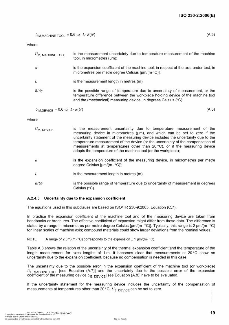
M,MACHINE TOOL 0,6 ( )U L Rα Θ= ⋅ ⋅ ⋅ (A.5)
where
UM, MACHINE TOOL is the measurement uncertainty due to temperature measurement of the machine tool, in micrometres (µm);
α is the expansion coefficient of the machine tool, in respect of the axis under test, in micrometres per metre degree Celsius [µm/(m⋅°C)];
L is the measurement length in metres (m);
R(Θ) is the possible range of temperature due to uncertainty of measurement, or the temperature difference between the workpiece holding device of the machine tool and the (mechanical) measuring device, in degrees Celsius (°C).
M,DEVICE 0,6 ( )U L Rα Θ= ⋅ ⋅ ⋅ (A.6)
where
UM, DEVICE is the measurement uncertainty due to temperature measurement of the measuring device in micrometres (µm), and which can be set to zero if the uncertainty statement of the measuring device includes the uncertainty due to the temperature measurement of the device (or the uncertainty of the compensation of measurements at temperatures other than 20 °C), or if the measuring device adopts the temperature of the machine tool (or the workpiece);
α is the expansion coefficient of the measuring device, in micrometres per metre degree Celsius [µm/(m ⋅ °C)];
L is the measurement length in metres (m);
R(Θ) is the possible range of temperature due to uncertainty of measurement in degrees Celsius (°C).
A.2.4.3 Uncertainty due to the expansion coefficient
The equations used in this subclause are based on ISO/TR 230-9:2005, Equation (C.7).
In practice the expansion coefficient of the machine tool and of the measuring device are taken from handbooks or brochures. The effective coefficient of expansion might differ from these data. The difference is stated by a range in micrometres per metre degree Celsius [µm/(m ⋅ °C)]. Typically, this range is 2 µm/(m ⋅ °C) for linear scales of machine axis; compound materials could show larger deviations from the nominal values.
NOTE A range of 2 µm/(m ⋅ °C) corresponds to the expression ± 1 µm/(m ⋅ °C).
Table A.3 shows the relation of the uncertainty of the thermal expansion coefficient and the temperature of the length measurement for axes lengths of 1 m. It becomes clear that measurements at 20 °C show no uncertainty due to the expansion coefficient, because no compensation is needed in this case.
The uncertainty due to the possible error in the expansion coefficient of the machine tool (or workpiece) UE, MACHINE TOOL [see Equation (A.7)] and the uncertainty due to the possible error of the expansion coefficient of the measuring device UE, DEVICE [see Equation (A.8)] have to be evaluated.
If the uncertainty statement for the measuring device includes the uncertainty of the compensation of measurements at temperatures other than 20 °C, UE, DEVICE can be set to zero.
Copyright International Organization for Standardization Provided by IHS under license with ISO
Not for ResaleNo reproduction or networking permitted without license from IHS
--`,,```,,,,````-`-`,,`,,`,`,,`---

ISO 230-2:2006(E)
20 © ISO 2006 – All rights reserved
Table A.3 — Measurement uncertainty due to the uncertainty of the thermal expansion coefficient
Coefficient for UE µm/m
Error range in expansion coefficient µm/ (m ⋅ °C)
Temperature °C
1 ± 0,5
2 ± 1,0
3 ± 1,5
4 ± 2,0
6 ± 3,0
5 9 17 26 35 52
10 6 12 17 23 35
15 3 6 9 12 17
18 1 2 3 5 7
19 1 1 2 2 3
20 0 0 0 0 0
21 1 1 2 2 3
22 1 2 3 5 7
25 3 6 9 12 17
30 6 12 17 23 35
35 9 17 26 35 52
UE = coefficient × L
UE µm
L m
E, MACHINE TOOL 0,6 ( )U T L R α= ⋅ ∆ ⋅ ⋅ (A.7)
where
UE, MACHINE TOOL is the measurement uncertainty due to the possible error in the thermal expansion coefficient of the machine tool (or the workpiece), in micrometres (µm);
∆T is the difference to 20 °C in degrees Celsius, ∆T = T − 20 °C;
T is the temperature of machine tool or workpiece in degrees Celsius (°C);
L is the measurement length in metres (m);
R(α) is the error range of expansion coefficient of machine tool (or workpiece), in micrometres per metre degree Celsius [µm/(m ⋅ °C)].
Copyright International Organization for Standardization Provided by IHS under license with ISO
Not for ResaleNo reproduction or networking permitted without license from IHS
--`,,```,,,,````-`-`,,`,,`,`,,`---

ISO 230-2:2006(E)
© ISO 2006 – All rights reserved 21
E, DEVICE 0,6 ( )U T L R α= ⋅ ∆ ⋅ ⋅ (A.8)
where
UE, DEVICE is the measurement uncertainty due to the possible error in the thermal expansion coefficient of the length measuring device, in micrometres (µm), and which can be set to zero, if the uncertainty statement of the measuring device includes the uncertainty due to the temperature measurement of the device (or the uncertainty of the compensation of measurements at temperatures other than 20 °C);
∆T is the difference to 20 °C in degrees Celsius, ∆T = T − 20 °C;
T temperature of the measuring device in degrees Celsius (°C);
L is the measurement length in metres (m);
R(α) is the error range of expansion coefficient of measuring device in micrometres per metre degree Celsius [µm/(m ⋅ °C)].
A.2.5 Uncertainty due to environmental variation error (EVE, or thermal drift), UEVE
The equation used in this subclause is based on ISO/TR 230-9:2005, C.2.5 and Equation (C.9).
During most measurements, temperature changes can be observed that might influence the machine tool and the measuring device. These effects, and especially any drift, shall be kept to a minimum according to 3.1 and 3.3.
The remaining effects are checked by a simple test: a drift test. Before starting the length measurements, the machine tool axis is moved to the extreme position (largest distance). During the approximate time needed for the length measurement the readout of the measuring device is recorded. The range of the readout, EVE, is the remaining environmental variation error that is used to estimate the corresponding uncertainty according to Equation (A.9).
0,6EVE VEU E= ⋅ (A.9)
where
UEVE is the measurement uncertainty due to environmental variation in micrometres (µm);
EVE is the range from drift test in micrometres (µm).
A.2.6 Correction of repeatability values due to environmental variation errors
This subclause is applicable only to axes up to 2 000 mm. Its equations are based on Clause 2 and A.2.4, and on ISO/TR 230-9:2005, C.2.5.
Any environmental variation error EVE will increase the standard deviation calculated from the repeated measurements of the axis, and therefore increase the repeatability values R, R↑, R↓. If a drift test is carried out and if the repeatability values are valid for longer measurement lengths of the axis under test, the repeatability values can be corrected as follows:
Copyright International Organization for Standardization Provided by IHS under license with ISO
Not for ResaleNo reproduction or networking permitted without license from IHS
--`,,```,,,,````-`-`,,`,,`,`,,`---

ISO 230-2:2006(E)
22 © ISO 2006 – All rights reserved
22 VE
,corrected 2E
i iU
s s ⎛ ⎞↑= ↑ −⎜ ⎟
⎝ ⎠
22 VE
,corrected 2E
i iU
s s ⎛ ⎞↓= ↓ −⎜ ⎟
⎝ ⎠
,corrected ,corrected
,corrected ,corrected
4
4i i
i i
R s
R s
↑= ⋅ ↑
↓= ⋅ ↓
,corrected ,corrected ,corrected ,corrected ,correctedmax. 2 2 ; ; i i i i i iR s s B R R⎡ ⎤= ⋅ ↑ + ⋅ ↓ + ↑ ↓⎣ ⎦
Rcorrected ↑ = max. [Ri, corrected↑]
Rcorrected ↓ = max. [Ri, corrected↓]
Rcorrected = max. [Ri, corrected] (A.10)
where
si,corrected↑,↓ is the corrected estimator for unidirectional axis repeatability si, correction due to environmental influences;
si is the estimator of the unidirectional axis repeatability of positioning, see 2.15;
UEVE is the measurement uncertainty due to environmental variations;
Ri,corrected↑,↓ is the corrected unidirectional repeatability of positioning at a position i, correction due to environmental influences;
Ri,corrected is the corrected bi-directional repeatability of positioning at a position i, correction due to environmental influences;
Rcorrected↑,↓ is the corrected unidirectional repeatability of positioning, correction due to environmental influences;
Rcorrected is the corrected bi-directional repeatability of positioning, correction due to environmental influences.
A.3 Estimation of uncertainty of parameters A, A↑, A↓, E, E↑, E↓, R, R↑, R↓, B
A.3.1 General
The equations used in this subclause (A.3.2 to A.3.6) are based on Clause 2 and on ISO/TR 230-9:2005, C.4. For linear axes up to 2 000 mm, five runs upwards and five runs downwards are assumed; for linear axes exceeding 2 000 mm, only one run upwards and downwards.
The following contributors to the measurement uncertainty are taken into account: measuring device, misalignment of the device to the machine axis under test, temperature measurement for machine tool and measuring device, thermal expansion coefficient of machine tool and measuring device, environmental variation error (EVE).
Copyright International Organization for Standardization Provided by IHS under license with ISO
Not for ResaleNo reproduction or networking permitted without license from IHS
--`,,```,,,,````-`-`,,`,,`,`,,`---

ISO 230-2:2006(E)
© ISO 2006 – All rights reserved 23
A.3.2 Uncertainty estimation for unidirectional repeatability, U(R↑, R↓)
This subclause is applicable only to axes up to 2 000 mm. The equation used is based on ISO/TR 230-9:2005, C.4.3 and Equation (C.14).
EVE( , ) 2U R R U↑ ↓ = ⋅ (A.11)
where U(R↑, R↓) is the uncertainty of the unidirectional repeatability, k = 2, for five measurement runs, in micrometres (µm).
A.3.3 Uncertainty estimation for reversal value, U(B)
The equations used in this subclause are based on of ISO/TR 230-9:2005, C.4.2 and Equation (C.14).
a) For axes up to 2 000 mm
EVE( ) 0,9U B U= ⋅ (A.12)
where U(B) is the measurement uncertainty of reversal value, k = 2, for five measurement runs, in micrometres (µm).
b) For axes exceeding 2 000 mm
EVE( ) 2U B U= ⋅ (A.13)
where U(B) is the measurement uncertainty of reversal value, k = 2, for one measurement run, in micrometres (µm).
A.3.4 Uncertainty of bi-directional repeatability, U(R)
This subclause is applicable only to axes up to 2 000 mm. Its equation is based on ISO/TR 230-9:2005, C.4.4 and Equation (C.15).
EVE( ) 2,2U R U= ⋅ (A.14)
where U(R) is the measurement uncertainty of bi-directional repeatability, k = 2, for five measurement runs, in micrometres (µm).
A.3.5 Uncertainty of the systematic deviations, U(M, E, E↑, E↓)
The equations used in this subclause are based on ISO/TR 230-9:2005, C.4.5 and Equation (C.16).
a) For axes up to 2 000 mm
U(E, E↑, E↓) =
2 2 2 2 2 2 2DEVICE MISALIGNMENT M, MACHINE TOOL M, DEVICE E, MACHINE TOOL E, DEVICE VE
15 EU U U U U U U+ + + + + + ⋅
(A.15)
where U(E, E↑, E↓) is the measurement uncertainty of systematic deviations, k = 2, for five measurement runs, in micrometres (µm).
Copyright International Organization for Standardization Provided by IHS under license with ISO
Not for ResaleNo reproduction or networking permitted without license from IHS
--`,,```,,,,````-`-`,,`,,`,`,,`---

ISO 230-2:2006(E)
24 © ISO 2006 – All rights reserved
U(M) =
2 2 2 2 2 2 2DEVICE MISALIGNMENT M, MACHINE TOOL M, DEVICE E, MACHINE TOOL E, DEVICE VE
110 EU U U U U U U+ + + + + + ⋅
(A.16)
where U(M) is the measurement uncertainty of the mean positional deviation M, k = 2, for five measurement runs, in micrometres (µm).
b) For axes exceeding 2 000 mm
U(E, E↑, E↓) =
2 2 2 2 2 2 2DEVICE MISALIGNMENT M, MACHINE_TOOL M,DEVICE E, MACHINE_TOOL E, DEVICE VEEU U U U U U U+ + + + + +
(A.17)
where U(E, E↑, E↓) is the measurement uncertainty of systematic deviations, k = 2, for one measurement run, in micrometres (µm).
U(M) =
2 2 2 2 2 2 2DEVICE MISALIGNMENT M, MACHINE_TOOL M, DEVICE E, MACHINE_TOOL E, DEVICE VE
12 EU U U U U U U+ + + + + + ⋅
(A.18)
where U(M) is the measurement uncertainty of mean positional deviation M, k = 2, for one measurement run, in micrometres (µm).
A.3.6 Uncertainty of accuracy of positioning, U(A, A↑, A↓)
The equation used in this subclause is based on ISO/TR 230-9:2005, C.4.6 and Equation (C.17).
2 2( , , ) ( ) ( , )U A A A U E U R R↑ ↓ = + ↑ ↓ (A.19)
where U(A,A↑,A↓) is the measurement uncertainty of accuracy of positioning, k = 2, for five measurement runs, in micrometres (µm).
A.4 Examples of uncertainty estimation
This clause provides four examples for measurement uncertainty estimations: two for laser interferometer measurements and two for linear scale measurements; for both measuring devices the estimation is done for average industrial conditions and for improved conditions.
Average industrial conditions are defined (see also Table A.4 and Table A.6):
⎯ the measuring device is not calibrated;
⎯ alignment
⎯ for the laser interferometer, the return beam has sufficient intensity (not recommended),
Copyright International Organization for Standardization Provided by IHS under license with ISO
Not for ResaleNo reproduction or networking permitted without license from IHS
--`,,```,,,,````-`-`,,`,,`,`,,`---

ISO 230-2:2006(E)
© ISO 2006 – All rights reserved 25
⎯ for the linear scale, aligned via a side surface within 0,5 mm;
⎯ temperature in workshop is 20 °C ± 5 °C;
⎯ temperature measurement
⎯ for the laser interferometer, the range of error of temperature measurement of machine tool is 0,7 °C
⎯ for the linear scale, the difference to machine temperature is 0,1 °C (generally reached after some minutes);
⎯ possible error of thermal expansion coefficients is 2 µm/(m ⋅ °C);
⎯ environmental variation error (EVE) is 1,7 µm.
Improved industrial conditions are defined as (see also Table A.5 and Table A.7):
⎯ the measuring device is calibrated
⎯ alignment:
⎯ for the laser interferometer, the return beam is aligned within 1 mm (recommended procedure),
⎯ for the linear scale, aligned via a side surface within 0,5 mm.
⎯ temperature in workshop is 20 °C ± 1 °C
⎯ temperature measurement:
⎯ for the laser interferometer, the range of error of temperature measurement of machine tool is 0,2 °C
⎯ for the linear scale, the difference to machine temperature is 0,05 °C (generally reached after less than 10 min);
⎯ possible error of thermal expansion coefficients is 2 µm/(m ⋅ °C)
⎯ environmental variation error (EVE) is 1,7 µm, although improved industrial conditions will show smaller EVE values.
Under average industrial conditions, the measurement uncertainty for the accuracy of positioning U(A) is 15 µm for laser interferometer and linear scale, for an axis length of 1 750 mm and for the conditions stated (see Tables A.4 and A.6). The statement for the positioning accuracy A should be A = 6 µm ± 15 µm (k = 2).
Under improved industrial conditions, the measurement uncertainty for the accuracy of positioning U(A) is 4 µm for laser interferometer and linear scale, for an axis length of 1 750 mm and for the conditions stated (see Table A.5 and Table A.7). The statement for the positioning accuracy A should be A = 6 µm ± 4 µm (k = 2).
The example for the correction of repeatability values due to uncertainty associated with environmental variation error is shown in Table A.8.
Copyright International Organization for Standardization Provided by IHS under license with ISO
Not for ResaleNo reproduction or networking permitted without license from IHS
--`,,```,,,,````-`-`,,`,,`,`,,`---

ISO 230-2:2006(E)
26 © ISO 2006 – All rights reserved
Table A.4 — Example estimation of measurement uncertainty for laser positioning measurement using laser interferometer under average industrial conditions
Positioning measurement
Estimation of measurement uncertainty, laser interferometer measurement
Simplified method
Average industrial conditions
Contributors Parameter Unit U Unit Equation
Device
measurement length 1 751,000 mm
error range 3,400 ppm
U(DEVICE) 3,6 µm A.3
Alignment
beam alignment
alignment, assumed 4,000 mm
measurement length 1 751,000 mm
U(MISALIGNMENT) 2,7 µm A.4
Compensation of workpiece temperature
measurement length 1 751,000 mm
thermal expansion coefficient 12,000 µm/(m ⋅ °C)
difference to 20 °C, maximum 5,000 °C
temperature measurement
deviation, maximum 0,700 °C
U(M, MACHINE TOOL) 8,8 µm A.5
U(M, DEVICE) zero, included in U(DEVICE)
uncertainty of expansion coefficient 2,000 µm/(m ⋅ °C)
U(E, MACHINE TOOL) 10,5 µm A.7
U(E, DEVICE) zero, included in U(DEVICE)
EVE, environmental variation
EVE 1,700 µm
U(EVE) 1,0 µm A.9
U(R+, R−) 2 µm A.11
U(B) 1 µm A.12
U(R) 2 µm A.14
U(E,E+,E−) 14 µm A.15
U(M) 14 µm A.16
U(A) 15 µm A.19
Copyright International Organization for Standardization Provided by IHS under license with ISO
Not for ResaleNo reproduction or networking permitted without license from IHS
--`,,```,,,,````-`-`,,`,,`,`,,`---

ISO 230-2:2006(E)
© ISO 2006 – All rights reserved 27
Table A.5 — Example estimation of measurement uncertainty for laser positioning measurement using laser interferometer under improved industrial conditions
Positioning measurement
Estimation of measurement uncertainty, laser interferometer measurement
Simplified method
Improved industrial conditions
Contributors Parameter Unit U Unit Equation
Device
measurement length 1 751,000 mm
error range 1,7 µm
U(DEVICE) 1,7 µm A.1
Alignment
beam alignment
alignment, assumed 1.000 mm
measurement length 1 751,000 mm
U(MISALIGNMENT) 0,2 µm A.4
Compensation of workpiece temperature
measurement length 1 751,000 mm
thermal expansion coefficient 12,000 µm/(m ⋅ °C)
difference to 20 °C, maximum 1,000 °C
temperature measurement
deviation, maximum 0,200 °C
U(M, MACHINE TOOL) 2,5 µm A.5
U(M, DEVICE) zero, included in U(DEVICE)
uncertainty of expansion coefficient 2,000 µm/(m ⋅ °C)
U(E, MACHINE TOOL) 2,1 µm A.7
U(E, DEVICE) zero, included in U(DEVICE)
EVE, environmental variation
EVE 1,700 µm
U(EVE) 1,0 µm A.9
U(R+, R−) 2,0 µm A.11
U(B) 0,9 µm A.12
U(R) 2,2 µm A.14
U(E,E+,E−) 3,7 µm A.15
U(M) 3,7 µm A.16
U(A) 4,2 µm A.19
Copyright International Organization for Standardization Provided by IHS under license with ISO
Not for ResaleNo reproduction or networking permitted without license from IHS
--`,,```,,,,````-`-`,,`,,`,`,,`---

ISO 230-2:2006(E)
28 © ISO 2006 – All rights reserved
Table A.6 — Example estimation of measurement uncertainty for linear positioning measurement using linear scale under average industrial conditions
Positioning measurement
Estimation of measurement uncertainty, linear scale measurement
Simplified method
Average industrial conditions
Contributors Parameter Unit U Unit Equation
Device
measurement length 1 751,000 mm
error range 2,000 µm/m
U(DEVICE) 2,1 µm A.3
Alignment
beam alignment
alignment, assumed 0,500 mm
measurement length 1 751,000 mm
U(MISALIGNMENT) 0,0 µm A.2
Compensation of workpiece temperature
measurement length 1 751,000 mm
thermal expansion coefficient 12,000 µm/(m ⋅ °C)
difference to 20 °C, maximum 5,000 °C
temperature measurement
deviation, maximum 0,100 °C
U(M, MACHINE TOOL) 1,3 µm A.5
U(M, DEVICE) zero, device adopts temperature of machine
uncertainty of expansion coefficient 2,000 µm/(m ⋅ °C)
U(E, MACHINE TOOL) 2,000 µm/(m ⋅ °C)
U(E, DEVICE) 10,5 µm A.7
EVE, environmental variation 10,5 µm A.8
EVE 1,700 µm
U(EVE) 1,0 µm A.9
U(R+, R−) 2 µm A.11
U(B) 1 µm A.12
U(R) 2 µm A.14
U(E,E+,E−) 15 µm A.15
U(M) 15 µm A.16
U(A) 15 µm A.19
Copyright International Organization for Standardization Provided by IHS under license with ISO
Not for ResaleNo reproduction or networking permitted without license from IHS
--`,,```,,,,````-`-`,,`,,`,`,,`---

ISO 230-2:2006(E)
© ISO 2006 – All rights reserved 29
Table A.7 — Example estimation of measurement uncertainty for linear positioning measurement using linear scale under improved industrial conditions
Positioning measurement
Estimation of measurement uncertainty, linear scale measurement
Simplified method
Improved industrial conditions
Contributors Parameter Unit U Unit Equation
Device
measurement length 1 751,000 mm
error range 1,0 µm/m
U(DEVICE) 1,8 µm A.2
Alignment
beam alignment
alignment, assumed 0,500 mm
measurement length 1 751,000 mm
U(MISALIGNMENT) 0,0 µm A.4
Compensation of workpiece temperature
measurement length 1 751,000 mm
thermal expansion coefficient 12,000 µm/(m ⋅ °C)
difference to 20 °C, maximum 1,000 °C
temperature measurement
deviation, maximum 0,050 °C
U(M, MACHINE TOOL) 0,6 µm A.5
U(M, DEVICE) zero, device adopts temperature of machine
uncertainty of expansion coefficient 2,000 µm/(m ⋅ °C)
U(E, MACHINE TOOL) 2,000 °C
U(E, DEVICE) 2,1 µm A.7
EVE, environmental variation 2,1 µm A.8
EVE 1,700 µm
U(EVE) 1,0 µm A.9
U(R+, R−) 2,0 µm A.11
U(B) 0,9 µm A.12
U(R) 2,2 µm A.14
U(E,E+,E−) 3,5 µm A.15
U(M) 3,5 µm A.16
U(A) 4,1 µm A.19
Copyright International Organization for Standardization Provided by IHS under license with ISO
Not for ResaleNo reproduction or networking permitted without license from IHS
--`,,```,,,,````-`-`,,`,,`,`,,`---

ISO 230-2:2006(E)
30 © ISO 2006 – All rights reserved
Table A.8 — Example for the correction of repeatability values due to uncertainty associated with environmental variation error
Positioning measurement
Correction of R values due to U(EVE)
Parameters Unit U Unit Equation
EVE, environmental variation
EVE 1,700 µm
U(EVE) 1,0 µm A.9
Correction of repeatability values Uncorrected Corrected
R+ according to Table 2, typical results 2,98 2,18 µm A.10
R− according to Table 2, typical results 2,55 1,53 µm A.10
s+ (at target 9) for R according to Table 2, typical results 0,746 0,544 µm A.10
s− (at target 9) for R according to Table 2, typical results 0,638 0,383 µm A.10
B (at target 9) for R according to Table 2, typical results 3,9 µm
R according to Table 2, typical results 6,7 5,8 µm A.10
Copyright International Organization for Standardization Provided by IHS under license with ISO
Not for ResaleNo reproduction or networking permitted without license from IHS
--`,,```,,,,````-`-`,,`,,`,`,,`---

ISO 230-2:2006(E)
© ISO 2006 – All rights reserved 31
Annex B (informative)
Step cycle
This annex addresses the application of an optional test cycle: the step cycle (see Figure B.1).
Figure B.1 — Step cycle
The results from tests made using this method could be different from those obtained from the standard test cycle shown in Figure 1.
With the standard test cycle, the approach to the extreme target positions from opposing directions takes place with a large difference in time intervals. However, with the step cycle the approach to the target positions from either direction takes place within shorter time intervals and a longer time is taken between the measurements of the first and the last target positions.
Measurements according to the standard test cycle could reflect thermal influences, which affect differently the various target positions along the axis under test. Here, thermal influences during the measurements could be evident in both the reversal values B and the repeatability R.
In the case of the step cycle, thermal influences could be evident in the range of the mean bi-directional positional deviation, M, whereas the reversal values and repeatability will be only slightly affected by the thermal behaviour of the machine.
Copyright International Organization for Standardization Provided by IHS under license with ISO
Not for ResaleNo reproduction or networking permitted without license from IHS
--`,,```,,,,````-`-`,,`,,`,`,,`---

ISO 230-2:2006(E)
32 © ISO 2006 – All rights reserved
Bibliography
[1] ISO 230-3:—1), Test code for machine tools — Part 3: Determination of thermal effects
[2] ISO/TR 230-9:2005, Test code for machine tools — Part 9: Estimation of measurement uncertainty for machine tool tests according to series ISO 230, basic equations
1) To be published. (Revision of ISO 230-3:2001)
Copyright International Organization for Standardization Provided by IHS under license with ISO
Not for ResaleNo reproduction or networking permitted without license from IHS
--`,,```,,,,````-`-`,,`,,`,`,,`---

Copyright International Organization for Standardization Provided by IHS under license with ISO
Not for ResaleNo reproduction or networking permitted without license from IHS
--`,,```,,,,````-`-`,,`,,`,`,,`---

ISO 230-2:2006(E)
ICS 25.040.20; 25.080.01 Price based on 32 pages
© ISO 2006 – All rights reserved
Copyright International Organization for Standardization Provided by IHS under license with ISO
Not for ResaleNo reproduction or networking permitted without license from IHS
--`,,```,,,,````-`-`,,`,,`,`,,`---