norme cei internationale iec …cpip.dfl.com.cn/stdfdld/dfl200900232.pdfnumérotation des...
TRANSCRIPT

NORME INTERNATIONALE
CEIIEC
INTERNATIONAL STANDARD
60317-0-3Edition 2.2
2004-11
Spécifications pour types particuliers de fils de bobinage –
Partie 0-3: Prescriptions générales – Fil de section circulaire en aluminium émaillé
Specifications for particular types of winding wires –
Part 0-3: General requirements – Enamelled round aluminium wire
Numéro de référence Reference number
CEI/IEC 60317-0-3:1997+A1:1999+A2:2004
Edition 2:1997 consolidée par les amendements 1:1999 et 2:2004 Edition 2:1997 consolidated with amendments 1:1999 and 2:2004
Copyright International Electrotechnical Commission Provided by IHS under license with IEC
Not for ResaleNo reproduction or networking permitted without license from IHS
--`,,,`,,-`-`,,`,,`,`,,`---

Numérotation des publications
Depuis le 1er janvier 1997, les publications de la CEI sont numérotées à partir de 60000. Ainsi, la CEI 34-1 devient la CEI 60034-1.
Editions consolidées
Les versions consolidées de certaines publications de la CEI incorporant les amendements sont disponibles. Par exemple, les numéros d’édition 1.0, 1.1 et 1.2 indiquent respectivement la publication de base, la publication de base incorporant l’amendement 1, et la publication de base incorporant les amendements 1 et 2.
Informations supplémentaires sur les publications de la CEI
Le contenu technique des publications de la CEI est constamment revu par la CEI afin qu'il reflète l'état actuel de la technique. Des renseignements relatifs à cette publication, y compris sa validité, sont dispo-nibles dans le Catalogue des publications de la CEI (voir ci-dessous) en plus des nouvelles éditions, amendements et corrigenda. Des informations sur les sujets à l’étude et l’avancement des travaux entrepris par le comité d’études qui a élaboré cette publication, ainsi que la liste des publications parues, sont également disponibles par l’intermédiaire de:
• Site web de la CEI (www.iec.ch)
• Catalogue des publications de la CEI
Le catalogue en ligne sur le site web de la CEI (www.iec.ch/searchpub) vous permet de faire des recherches en utilisant de nombreux critères, comprenant des recherches textuelles, par comité d’études ou date de publication. Des informations en ligne sont également disponibles sur les nouvelles publications, les publications remplacées ou retirées, ainsi que sur les corrigenda.
• IEC Just Published
Ce résumé des dernières publications parues (www.iec.ch/online_news/justpub) est aussi dispo-nible par courrier électronique. Veuillez prendre contact avec le Service client (voir ci-dessous) pour plus d’informations.
• Service clients
Si vous avez des questions au sujet de cette publication ou avez besoin de renseignements supplémentaires, prenez contact avec le Service clients:
Email: [email protected] Tél: +41 22 919 02 11 Fax: +41 22 919 03 00
Publication numbering
As from 1 January 1997 all IEC publications are issued with a designation in the 60000 series. For example, IEC 34-1 is now referred to as IEC 60034-1.
Consolidated editions
The IEC is now publishing consolidated versions of its publications. For example, edition numbers 1.0, 1.1 and 1.2 refer, respectively, to the base publication, the base publication incorporating amendment 1 and the base publication incorporating amendments 1 and 2.
Further information on IEC publications
The technical content of IEC publications is kept under constant review by the IEC, thus ensuring that the content reflects current technology. Information relating to this publication, including its validity, is available in the IEC Catalogue of publications (see below) in addition to new editions, amendments and corrigenda. Information on the subjects under consideration and work in progress undertaken by the technical committee which has prepared this publication, as well as the list of publications issued, is also available from the following:
• IEC Web Site (www.iec.ch)
• Catalogue of IEC publications
The on-line catalogue on the IEC web site (www.iec.ch/searchpub) enables you to search by a variety of criteria including text searches, technical committees and date of publication. On-line information is also available on recently issued publications, withdrawn and replaced publications, as well as corrigenda.
• IEC Just Published
This summary of recently issued publications (www.iec.ch/online_news/justpub) is also available by email. Please contact the Customer Service Centre (see below) for further information.
• Customer Service Centre
If you have any questions regarding this publication or need further assistance, please contact the Customer Service Centre:
Email: [email protected] Tel: +41 22 919 02 11 Fax: +41 22 919 03 00
.
Copyright International Electrotechnical Commission Provided by IHS under license with IEC
Not for ResaleNo reproduction or networking permitted without license from IHS
--`,,,`,,-`-`,,`,,`,`,,`---

NORME INTERNATIONALE
CEIIEC
INTERNATIONAL STANDARD
60317-0-3Edition 2.2
2004-11
Spécifications pour types particuliers de fils de bobinage –
Partie 0-3: Prescriptions générales – Fil de section circulaire en aluminium émaillé
Specifications for particular types of winding wires –
Part 0-3: General requirements – Enamelled round aluminium wire
Pour prix, voir catalogue en vigueur For price, see current catalogue
IEC 2004 Droits de reproduction réservés Copyright - all rights reserved
Aucune partie de cette publication ne peut être reproduite ni utilisée sous quelque forme que ce soit et par aucun procédé, électronique ou mécanique, y compris la photocopie et les microfilms, sans l'accord écrit de l'éditeur.
No part of this publication may be reproduced or utilized in any form or by any means, electronic or mechanical, including photocopying and microfilm, without permission in writing from the publisher.
International Electrotechnical Commission, 3, rue de Varembé, PO Box 131, CH-1211 Geneva 20, Switzerland Telephone: +41 22 919 02 11 Telefax: +41 22 919 03 00 E-mail: [email protected] Web: www.iec.ch
S Commission Electrotechnique InternationaleInternational Electrotechnical CommissionМеждународная Электротехническая Комиссия
CODE PRIX PRICE CODE
Edition 2:1997 consolidée par les amendements 1:1999 et 2:2004 Edition 2:1997 consolidated with amendments 1:1999 and 2:2004
Copyright International Electrotechnical Commission Provided by IHS under license with IEC
Not for ResaleNo reproduction or networking permitted without license from IHS
--`,,,`,,-`-`,,`,,`,`,,`---

– 2 – 60317-0-3 CEI:1997+A1:1999+A2:2004
SOMMAIRE
AVANT-PROPOS ....................................................................................................................4 INTRODUCTION.....................................................................................................................8 1 Domaine d'application..................................................................................................... 10 2 Références normatives ................................................................................................... 10 3 Termes et définitions et notes générales concernant les méthodes d'essai et l’aspect ..... 12 4 Dimensions.....................................................................................................................14 5 Résistance électrique...................................................................................................... 20 6 Allongement ................................................................................................................... 20 7 Effet de ressort ...............................................................................................................20 8 Souplesse et adhérence.................................................................................................. 20 9 Choc thermique .............................................................................................................. 22 10 Thermoplasticité ............................................................................................................. 22 11 Résistance à l'abrasion ................................................................................................... 24 12 Résistance aux solvants ................................................................................................. 24 13 Tension de claquage....................................................................................................... 24 14 Continuité de l'isolant (diamètres nominaux des conducteurs
jusqu'à et y compris 1,600 mm)....................................................................................... 26 15 Indice de température ..................................................................................................... 26 16 Résistance aux réfrigérants ............................................................................................ 26 17 Brasabilité ...................................................................................................................... 28 18 Adhérence par chaleur ou par solvant ............................................................................. 28 19 Facteur de dissipation diélectrique .................................................................................. 28 20 Résistance à l'huile de transformateur............................................................................. 28 21 Perte de masse .............................................................................................................. 28 23 Détection des micro-fissures en immersion ..................................................................... 28 30 Conditionnement ............................................................................................................ 28 Annexe A (informative) Dimensions pour les diamètres nominaux des conducteurs intermédiaires (R 40).............................................................................................................30 Annexe B (supprimée)...........................................................................................................34 Annexe C (informative) Méthode pour le calcul de la résistance linéique..............................36 Annexe D (informative) Résistance .....................................................................................38 Annexe E (informative) Essai de défaillance à haute température ........................................40 Tableau 1 – Dimensions pour les fils émaillés (R 20) .............................................................16 Tableau 2 – Dimensions pour les fils émaillés avec une couche adhérente (R 20)..................18 Tableau 3 – Allongement.......................................................................................................20 Tableau 4 – Enroulement sur mandrin ...................................................................................22 Tableau 5 – Choc thermique .................................................................................................22 Tableau 6 – Tension de claquage ..........................................................................................24 Tableau 7 – Tension de claquage ..........................................................................................26 Tableau 8 – Continuité de l'isolant .........................................................................................26 Tableau A.1 – Dimensions pour les fils émaillés (R 40)..........................................................30 Tableau A.2 – Dimensions pour les fils émaillés avec une couche adhérente (R 40) ..............32 Tableau D.1 – Résistances électriques ..................................................................................38
Copyright International Electrotechnical Commission Provided by IHS under license with IEC
Not for ResaleNo reproduction or networking permitted without license from IHS
--`,,,`,,-`-`,,`,,`,`,,`---

60317-0-3 IEC:1997+A1:1999+A2:2004 – 3 –
CONTENTS
FOREWORD...........................................................................................................................5 INTRODUCTION.....................................................................................................................9 1 Scope ............................................................................................................................. 11 2 Normative references...................................................................................................... 11 3 Terms and definitions, general notes on methods of tests and appearance...................... 13 4 Dimensions.....................................................................................................................15 5 Electrical resistance........................................................................................................ 21 6 Elongation ...................................................................................................................... 21 7 Springiness..................................................................................................................... 21 8 Flexibility and adherence ................................................................................................ 21 9 Heat shock .....................................................................................................................23 10 Cut-through ....................................................................................................................23 11 Resistance to abrasion ................................................................................................... 25 12 Resistance to solvents .................................................................................................... 25 13 Breakdown voltage ......................................................................................................... 25 14 Continuity of insulation (nominal conductor diameters up to and including 1,600 mm) ...... 27 15 Temperature index.......................................................................................................... 27 16 Resistance to refrigerants ............................................................................................... 27 17 Solderability.................................................................................................................... 29 18 Heat or solvent bonding .................................................................................................. 29 19 Dielectric dissipation factor ............................................................................................. 29 20 Resistance to transformer oil .......................................................................................... 29 21 Loss of mass .................................................................................................................. 29 23 Pin hole test ................................................................................................................... 29 30 Packaging ...................................................................................................................... 29 Annex A (informative) Dimensions for intermediate nominal conductor diameters (R 40)......31 Annex B (deleted) .................................................................................................................35 Annex C (informative) Method for the calculation of linear resistance...................................37 Annex D (informative) Resistance .......................................................................................39 Annex E (informative) High temperature failure test .............................................................41 Table 1 – Dimensions of enamelled wires (R 20) ...................................................................17 Table 2 – Dimensions of enamelled wires with a bonding layer (R 20) ....................................19 Table 3 – Elongation .............................................................................................................21 Table 4 – Mandrel winding.....................................................................................................23 Table 5 – Heat shock ............................................................................................................23 Table 6 – Breakdown voltage ................................................................................................25 Table 7 – Breakdown voltage ................................................................................................27 Table 8 – Continuity of insulation...........................................................................................27 Table A.1 – Dimensions of enamelled wires (R 40) ................................................................31 Table A.2 – Dimensions of enamelled wires with a bonding layer (R 40).................................33 Table D.1 – Electrical resistances .........................................................................................39
Copyright International Electrotechnical Commission Provided by IHS under license with IEC
Not for ResaleNo reproduction or networking permitted without license from IHS
--`,,,`,,-`-`,,`,,`,`,,`---

– 4 – 60317-0-3 CEI:1997+A1:1999+A2:2004
COMMISSION ÉLECTROTECHNIQUE INTERNATIONALE ____________
SPÉCIFICATIONS POUR TYPES PARTICULIERS DE FILS DE BOBINAGE –
Partie 0-3: Prescriptions générales –
Fil de section circulaire en aluminium émaillé
AVANT-PROPOS
1) La Commission Electrotechnique Internationale (CEI) est une organisation mondiale de normalisation composée de l'ensemble des comités électrotechniques nationaux (Comités nationaux de la CEI). La CEI a pour objet de favoriser la coopération internationale pour toutes les questions de normalisation dans les domaines de l'électricité et de l'électronique. A cet effet, la CEI – entre autres activités – publie des Normes internationales, des Spécifications techniques, des Rapports techniques, des Spécifications accessibles au public (PAS) et des Guides (ci-après dénommés "Publication(s) de la CEI"). Leur élaboration est confiée à des comités d'études, aux travaux desquels tout Comité national intéressé par le sujet traité peut participer. Les organisations internationales, gouvernementales et non gouvernementales, en liaison avec la CEI, participent également aux travaux. La CEI collabore étroitement avec l'Organisation Internationale de Normalisation (ISO), selon des conditions fixées par accord entre les deux organisations.
2) Les décisions ou accords officiels de la CEI concernant les questions techniques représentent, dans la mesure du possible, un accord international sur les sujets étudiés, étant donné que les Comités nationaux de la CEI intéressés sont représentés dans chaque comité d’études.
3) Les Publications de la CEI se présentent sous la forme de recommandations internationales et sont agréées comme telles par les Comités nationaux de la CEI. Tous les efforts raisonnables sont entrepris afin que la CEI s'assure de l'exactitude du contenu technique de ses publications; la CEI ne peut pas être tenue responsable de l'éventuelle mauvaise utilisation ou interprétation qui en est faite par un quelconque utilisateur final.
4) Dans le but d'encourager l'uniformité internationale, les Comités nationaux de la CEI s'engagent, dans toute la mesure possible, à appliquer de façon transparente les Publications de la CEI dans leurs publications nationales et régionales. Toutes divergences entre toutes Publications de la CEI et toutes publications nationales ou régionales correspondantes doivent être indiquées en termes clairs dans ces dernières.
5) La CEI n’a prévu aucune procédure de marquage valant indication d’approbation et n'engage pas sa responsabilité pour les équipements déclarés conformes à une de ses Publications.
6) Tous les utilisateurs doivent s'assurer qu'ils sont en possession de la dernière édition de cette publication.
7) Aucune responsabilité ne doit être imputée à la CEI, à ses administrateurs, employés, auxiliaires ou mandataires, y compris ses experts particuliers et les membres de ses comités d'études et des Comités nationaux de la CEI, pour tout préjudice causé en cas de dommages corporels et matériels, ou de tout autre dommage de quelque nature que ce soit, directe ou indirecte, ou pour supporter les coûts (y compris les frais de justice) et les dépenses découlant de la publication ou de l'utilisation de cette Publication de la CEI ou de toute autre Publication de la CEI, ou au crédit qui lui est accordé.
8) L'attention est attirée sur les références normatives citées dans cette publication. L'utilisation de publications référencées est obligatoire pour une application correcte de la présente publication.
9) L’attention est attirée sur le fait que certains des éléments de la présente Publication de la CEI peuvent faire l’objet de droits de propriété intellectuelle ou de droits analogues. La CEI ne saurait être tenue pour responsable de ne pas avoir identifié de tels droits de propriété et de ne pas avoir signalé leur existence.
La Norme internationale CEI 60317-0-3 a été établie par le comité d’études 55 de la CEI: Fils de bobinage.
La présente norme comprend toutes les prescriptions générales pour les fils de section circulaire en cuivre émaillé contenues dans la série CEI 60317, publiée en 1988.
La présente version consolidée de la CEI 60317-0-3 est issue de la deuxième édition (1997) [documents 55/559, 55/610/FDIS et 55/603, 55/630/RVD], de son amendement 1 (1999) [documents 55/690/FDIS et 55/717/RVD] et de son amendement 2 (2004) [documents 55/913/FDIS et 55/921/RVD].
Elle porte le numéro d'édition 2.2.
Copyright International Electrotechnical Commission Provided by IHS under license with IEC
Not for ResaleNo reproduction or networking permitted without license from IHS
--`,,,`,,-`-`,,`,,`,`,,`---

60317-0-3 IEC:1997+A1:1999+A2:2004 – 5 –
INTERNATIONAL ELECTROTECHNICAL COMMISSION ____________
SPECIFICATIONS FOR PARTICULAR TYPES OF WINDING WIRES –
Part 0-3: General requirements – Enamelled round aluminium wire
FOREWORD
1) The International Electrotechnical Commission (IEC) is a worldwide organization for standardization comprising all national electrotechnical committees (IEC National Committees). The object of IEC is to promote international co-operation on all questions concerning standardization in the electrical and electronic fields. To this end and in addition to other activities, IEC publishes International Standards, Technical Specifications, Technical Reports, Publicly Available Specifications (PAS) and Guides (hereafter referred to as “IEC Publication(s)”). Their preparation is entrusted to technical committees; any IEC National Committee interested in the subject dealt with may participate in this preparatory work. International, governmental and non-governmental organizations liaising with the IEC also participate in this preparation. IEC collaborates closely with the International Organization for Standardization (ISO) in accordance with conditions determined by agreement between the two organizations.
2) The formal decisions or agreements of IEC on technical matters express, as nearly as possible, an international consensus of opinion on the relevant subjects since each technical committee has representation from all interested IEC National Committees.
3) IEC Publications have the form of recommendations for international use and are accepted by IEC National Committees in that sense. While all reasonable efforts are made to ensure that the technical content of IEC Publications is accurate, IEC cannot be held responsible for the way in which they are used or for any misinterpretation by any end user.
4) In order to promote international uniformity, IEC National Committees undertake to apply IEC Publications transparently to the maximum extent possible in their national and regional publications. Any divergence between any IEC Publication and the corresponding national or regional publication shall be clearly indicated in the latter.
5) IEC provides no marking procedure to indicate its approval and cannot be rendered responsible for any equipment declared to be in conformity with an IEC Publication.
6) All users should ensure that they have the latest edition of this publication.
7) No liability shall attach to IEC or its directors, employees, servants or agents including individual experts and members of its technical committees and IEC National Committees for any personal injury, property damage or other damage of any nature whatsoever, whether direct or indirect, or for costs (including legal fees) and expenses arising out of the publication, use of, or reliance upon, this IEC Publication or any other IEC Publications.
8) Attention is drawn to the Normative references cited in this publication. Use of the referenced publications is indispensable for the correct application of this publication.
9) Attention is drawn to the possibility that some of the elements of this IEC Publication may be the subject of patent rights. IEC shall not be held responsible for identifying any or all such patent rights.
International Standard IEC 60317-0-3 has been prepared by IEC technical committee 55: Winding wires.
This standard also contains all general requirements of enamelled round copper wires taken from the IEC 60317 series issued in 1988.
This consolidated version of IEC 60317-0-3 is based on the second edition (1997) [documents 55/559, 55/610/FDIS and 55/603, 55/630/RVD], its amendment 1 (1999) [documents 55/690/FDIS and 55/717/RVD] and its amendment 2 (2004) [documents 55/913/FDIS and 55/921/RVD].
It bears the edition number 2.2.
Copyright International Electrotechnical Commission Provided by IHS under license with IEC
Not for ResaleNo reproduction or networking permitted without license from IHS
--`,,,`,,-`-`,,`,,`,`,,`---

– 6 – 60317-0-3 CEI:1997+A1:1999+A2:2004
Une ligne verticale dans la marge indique où la publication de base a été modifiée par les amendements 1 et 2.
Les annexes A, C, D et E sont informatives.
Le comité a décidé que le contenu de la publication de base et de ses amendements ne sera pas modifié avant la date de maintenance indiquée sur le site web de la CEI sous "http://webstore.iec.ch" dans les données relatives à la publication recherchée. A cette date, la publication sera
• reconduite, • supprimée, • remplacée par une édition révisée, ou • amendée.
Copyright International Electrotechnical Commission Provided by IHS under license with IEC
Not for ResaleNo reproduction or networking permitted without license from IHS
--`,,,`,,-`-`,,`,,`,`,,`---

60317-0-3 IEC:1997+A1:1999+A2:2004 – 7 –
A vertical line in the margin shows where the base publication has been modified by amendments 1 and 2.
Annexes A, C, D and E are for information only.
The committee has decided that the contents of the base publication and its amendments will remain unchanged until the maintenance result date indicated on the IEC web site under "http://webstore.iec.ch" in the data related to the specific publication. At this date, the publication will be
• reconfirmed, • withdrawn, • replaced by a revised edition, or • amended.
Copyright International Electrotechnical Commission Provided by IHS under license with IEC
Not for ResaleNo reproduction or networking permitted without license from IHS
--`,,,`,,-`-`,,`,,`,`,,`---

– 8 – 60317-0-3 CEI:1997+A1:1999+A2:2004
INTRODUCTION
La présente partie de la CEI 60317 constitue l'un des éléments d'une série traitant des fils isolés utilisés dans les enroulements des appareils électriques. Cette série est composée de trois groupes définissant respectivement:
1) fils de bobinage et méthodes d'essai (CEI 60851); 2) spécifications pour types particuliers de fils de bobinage (CEI 60317); 3) conditionnement des fils de bobinage (CEI 60264).
Copyright International Electrotechnical Commission Provided by IHS under license with IEC
Not for ResaleNo reproduction or networking permitted without license from IHS
--`,,,`,,-`-`,,`,,`,`,,`---

60317-0-3 IEC:1997+A1:1999+A2:2004 – 9 –
INTRODUCTION
This part of IEC 60317 is one of a series that deals with insulated wires used for windings in electrical equipment. The series has three groups describing:
1) winding wires and test methods (IEC 60851); 2) specifications for particular types of winding wires (IEC 60317); 3) packaging of winding wires (IEC 60264).
Copyright International Electrotechnical Commission Provided by IHS under license with IEC
Not for ResaleNo reproduction or networking permitted without license from IHS
--`,,,`,,-`-`,,`,,`,`,,`---

– 10 – 60317-0-3 CEI:1997+A1:1999+A2:2004
SPÉCIFICATIONS POUR TYPES PARTICULIERS DE FILS DE BOBINAGE –
Partie 0-3: Prescriptions générales – Fil de section circulaire en aluminium émaillé
1 Domaine d'application
La présente Norme internationale spécifie les prescriptions générales pour les fils de bobinage de section circulaire en aluminium émaillé avec ou sans une couche adhérente.
La gamme des diamètres nominaux des conducteurs est donnée dans la feuille de spécification concernée.
Quand il est fait référence à un fil de bobinage conforme à la série CEI 60317 indiquée dans l'article 2, les informations suivantes sont données dans la description:
– la référence de la spécification CEI; – le diamètre nominal du conducteur en millimètres; – le grade.
EXEMPLE: CEI 60317-14 – 0,500 Grade 1
2 Références normatives
Les documents de référence suivants sont indispensables pour l'application du présent document. Pour les références datées, seule l'édition citée s'applique. Pour les références non datées, la dernière édition du document de référence s'applique (y compris les éventuels amendements).
CEI 60172, Méthode d'essai pour la détermination de l'indice de température des fils de bobinage émaillés
CEI 60317-14, Spécifications pour types particuliers de fils de bobinage – Partie 14: Fil de section circulaire en aluminium émaillé avec acétal de polyvinyle, classe 105
CEI 60317-25, Spécifications pour types particuliers de fils de bobinage – Partie 25: Fil de section circulaire en aluminium émaillé avec polyester ou polyesterimide et avec surcouche polyamide-imide, classe 200
CEI 60851(toutes les parties), Fils de bobinage – Méthodes d’essai
ISO 3, Nombres normaux – Séries de nombres normaux
Copyright International Electrotechnical Commission Provided by IHS under license with IEC
Not for ResaleNo reproduction or networking permitted without license from IHS
--`,,,`,,-`-`,,`,,`,`,,`---

60317-0-3 IEC:1997+A1:1999+A2:2004 – 11 –
SPECIFICATIONS FOR PARTICULAR TYPES OF WINDING WIRES –
Part 0-3: General requirements – Enamelled round aluminium wire
1 Scope
This International Standard specifies the general requirements of enamelled round aluminium winding wires with or without a bonding layer.
The range of nominal conductor diameters is given in the relevant specification sheet.
When reference is made to a winding wire according to a standard of the IEC 60317 series mentioned under clause 2, the following information is given in the description:
– reference to IEC specification; – nominal conductor diameter in millimetres; – grade.
EXAMPLE: IEC 60317-14 – 0,500 Grade 1
2 Normative references
The following referenced documents are indispensable for the application of this document. For dated references, only the edition cited applies. For undated references, the latest edition of the referenced document (including any amendments) applies.
IEC 60172, Test procedure for the determination of the temperature index of enamelled winding wires
IEC 60317-14, Specifications for particular types of winding wires – Part 14: Polyvinyl acetal enamelled round aluminium wire, class 105
IEC 60317-25, Specifications for particular types of winding wires – Part 25: Polyester or polyesterimide overcoated with polyamide-imide enamelled round aluminium wire, class 200
IEC 60851(all parts), Winding wires – Test methods
ISO 3, Preferred numbers – Series of preferred numbers
Copyright International Electrotechnical Commission Provided by IHS under license with IEC
Not for ResaleNo reproduction or networking permitted without license from IHS
--`,,,`,,-`-`,,`,,`,`,,`---

– 12 – 60317-0-3 CEI:1997+A1:1999+A2:2004
3 Termes et définitions et notes générales concernant les méthodes d'essai et l’aspect
3.1 Définitions
couche adhérente matériau qui est déposé sur un fil émaillé et qui a la fonction particulière de coller les fils entre eux
classe performance thermique d'un fil de bobinage exprimée par l'indice de température et la température de choc thermique
revêtement matériau qui est déposé sur un conducteur ou sur un fil par des moyens appropriés, puis séché et/ou cuit
conducteur métal nu après enlèvement de l'isolant
craquelure fente dans l'isolant qui rend visible le conducteur sous un grossissement donné
double revêtement isolant constitué de deux matériaux différents, l'un en sous-couche et l'autre en surcouche
fil émaillé fil revêtu d'un isolant fait d'une résine cuite
grade gamme d'épaisseurs d'isolant d'un fil
isolant revêtement ou enveloppe sur le conducteur qui a pour fonction particulière de supporter la tension électrique
dimension nominale du conducteur désignation de la taille du conducteur selon la CEI 60317
revêtement unique isolant constitué d'un seul matériau
fil de bobinage fil utilisé pour fabriquer un bobinage qui fournit un champ magnétique
fil conducteur revêtu ou enveloppé d'un isolant
vision normale vision parfaite, avec si nécessaire des lentilles correctives
Copyright International Electrotechnical Commission Provided by IHS under license with IEC
Not for ResaleNo reproduction or networking permitted without license from IHS
--`,,,`,,-`-`,,`,,`,`,,`---

60317-0-3 IEC:1997+A1:1999+A2:2004 – 13 –
3 Terms and definitions, general notes on methods of tests and appearance
3.1 Definitions
bonding layer a material which is deposited on an enamelled wire and which has the specific function of bonding wires together
class the thermal performance of a wire expressed by the temperature index and the heat shock temperature
coating a material which is deposited on a conductor or wire by a suitable means and then dried and/or cured
conductor the bare metal after removal of the insulation
crack an opening in the insulation which exposes the conductor to view at the stated magnification
dual coating an insulation composed of two different materials, an underlying and a superimposed coating
enamelled wire a wire coated with an insulation of cured resin
grade the range of thickness of the insulation of a wire
insulation a coating or covering on the conductor with the specific function of withstanding voltage
nominal conductor dimension the designation of the conductor size in accordance with IEC 60317
sole coating an insulation composed of one material
winding wire a wire used for winding a coil to provide a magnetic field
wire a conductor coated or covered with an insulation
normal vision 20/20 vision, with corrective lenses, if necessary
Copyright International Electrotechnical Commission Provided by IHS under license with IEC
Not for ResaleNo reproduction or networking permitted without license from IHS
--`,,,`,,-`-`,,`,,`,`,,`---
– 14 – 60317-0-3 CEI:1997+A1:1999+A2:2004
3.2 Notes générales concernant les méthodes d'essai
Toutes les méthodes d'essai utilisées dans la présente norme figurent dans la CEI 60851.
Les numéros d'articles dans la présente norme sont identiques aux numéros d'essais respectifs de la CEI 60851.
En cas de divergences entre la publication relative aux méthodes d'essai et la présente norme, la CEI 60317-0-3 prévaut.
Dans le cas où aucune gamme des diamètres nominaux des conducteurs n'est donnée pour un essai, l'essai s'applique à tous les diamètres nominaux des conducteurs couverts par la feuille particulière.
Sauf spécification contraire, tous les essais doivent être effectués à une température comprise entre 15 °C et 35 °C et une humidité relative de 45 % à 75 %. L'éprouvette doit, avant exécution des mesures, être préconditionnée dans ces conditions atmosphériques pendant un temps suffisant pour que l'éprouvette atteigne la stabilité.
Le fil à essayer doit être prélevé de son conditionnement de façon qu'il ne soit pas soumis à une tension ou à des pliages inutiles. Avant chaque essai, il convient d'éliminer une longueur de fil suffisante pour être sûr que les échantillons ne comportent aucun fil endommagé.
3.3 Aspects
Le film isolant doit être lisse et continu, exempt de rayures, de bulles ou de tout autre matériel étranger lorsqu'il est examiné à l'oeil nu quand il est enroulé sur la bobine d’origine.
En cas d'accord entre l'utilisateur et le fournisseur, un grossissement de 6× à 10× doit être utilisé pour examiner les fils ayant un diamètre nominal inférieur à 0,10 mm.
4 Dimensions
4.1 Diamètre du conducteur
La série des diamètres nominaux des conducteurs préférentiels doit correspondre à la série R 20 de l'ISO 3. Les valeurs réelles et leurs tolérances sont données dans les tableaux 1 et 2.
L'utilisateur peut choisir des diamètres intermédiaires pour des raisons techniques. Ces diamètres nominaux des conducteurs intermédiaires doivent être choisis dans la série R 40 de l'ISO 3. Les valeurs réelles et leurs tolérances sont données dans l'annexe A.
Le diamètre du conducteur ne doit pas s'écarter du diamètre nominal d'une valeur supérieure à la tolérance donnée dans les tableaux 1 ou 2.
Copyright International Electrotechnical Commission Provided by IHS under license with IEC
Not for ResaleNo reproduction or networking permitted without license from IHS
--`,,,`,,-`-`,,`,,`,`,,`---

60317-0-3 IEC:1997+A1:1999+A2:2004 – 15 –
3.2 General notes on methods of test
All methods of test to be used for this standard are given in IEC 60851.
The clause numbers used in this standard are identical with the respective test numbers of IEC 60851.
In case of inconsistencies between the publication on methods of test and this standard, IEC 60317-0-3 shall prevail.
Where no specific range of nominal conductor diameters is given for a test, the test applies to all nominal conductor diameters covered by the specification sheet.
Unless otherwise specified, all tests shall be carried out at a temperature from 15 °C to 35 °C and a relative humidity from 45 % to 75 %. Before measurements are made, the specimens shall be preconditioned under these atmospheric conditions for a time sufficient to allow the specimens to reach stability.
The wire to be tested shall be removed from the packaging in such a way that the wire will not be subjected to tension or unnecessary bends. Before each test, sufficient wire should be discarded to ensure that any damaged wire is not included in the test specimens.
3.3 Appearance
The film coating shall be smooth and continuous, free from streaks, blisters and foreign material when examined with normal vision, as wound on the original spool or reel.
When agreed upon between the user and supplier, examination using 6× to 10× magnification shall be used for wires with a nominal diameter less than 0,10 mm.
4 Dimensions
4.1 Conductor diameter
The series of preferred nominal conductor diameters shall correspond to series R 20 according to ISO 3. The actual values and their tolerances are given in tables 1 and 2.
The series of intermediate diameters from which the user may select intermediate nominal conductor diameters, when required for technical reasons, shall correspond to series R 40 according to ISO 3. The actual values and their tolerances are given in annex A.
The conductor diameter shall not differ from the nominal diameter by more than the limit given in tables 1 or 2.
Copyright International Electrotechnical Commission Provided by IHS under license with IEC
Not for ResaleNo reproduction or networking permitted without license from IHS
--`,,,`,,-`-`,,`,,`,`,,`---

– 16 – 60317-0-3 CEI:1997+A1:1999+A2:2004
Tableau 1 – Dimensions pour les fils émaillés (R 20)
Diamètre nominal du conducteur
Tolérance du conducteur
±±±±
Accroissement minimal dû à l'isolant
mm
Diamètre extérieur maximal
mm
mm mm Grade 1 Grade 2 Grade 3 Grade 1 Grade 2 Grade 3
0,250 0,280 0,315 0,355 0,400
0,004 0,004 0,004 0,004 0,005
0,017 0,018 0,019 0,020 0,021
0,032 0,033 0,035 0,038 0,040
0,048 0,050 0,053 0,057 0,060
0,281 0,312 0,349 0,392 0,439
0,297 0,329 0,367 0,411 0,459
0,312 0,345 0,384 0,428 0,478
0,450 0,500 0,560 0,630 0,710
0,005 0,005 0,006 0,006 0,007
0,022 0,024 0,025 0,027 0,028
0,042 0,045 0,047 0,050 0,053
0,064 0,067 0,071 0,075 0,080
0,491 0,544 0,606 0,679 0,762
0,513 0,566 0,630 0,704 0,789
0,533 0,587 0,653 0,728 0,814
0,800 0,900 1,000 1,120 1,250
0,008 0,009 0,010 0,011 0,013
0,030 0,032 0,034 0,034 0,035
0,056 0,060 0,063 0,065 0,067
0,085 0,090 0,095 0,098 0,100
0,855 0,959 1,062 1,184 1,316
0,884 0,989 1,094 1,217 1,349
0,911 1,018 1,124 1,248 1,381
1,400 1,600 1,800 2,000 2,240
0,014 0,016 0,018 0,020 0,022
0,036 0,038 0,039 0,040 0,041
0,069 0,071 0,073 0,075 0,077
0,103 0,107 0,110 0,113 0,116
1,468 1,670 1,872 2,074 2,316
1,502 1,706 1,909 2,112 2,355
1,535 1,740 1,944 2,148 2,392
2,500 2,800 3,150 3,550 4,000
0,025 0,028 0,032 0,036 0,040
0,042 0,043 0,045 0,046 0,047
0,079 0,081 0,084 0,086 0,089
0,119 0,123 0,127 0,130 0,134
2,578 2,880 3,233 3,635 4,088
2,618 2,922 3,276 3,679 4,133
2,656 2,961 3,316 3,721 4,176
4,500 5,000
0,045 0,050
0,049 0,050
0,092 0,094
0,138 0,142
4,591 5,093
4,637 5,141
4,681 5,186
NOTE 1 Pour les diamètres nominaux des conducteurs intermédiaires, utiliser la valeur de l'accroissement minimal correspondant à celui du diamètre nominal du conducteur immédiatement supérieur.
NOTE 2 Pour les dimensions des diamètres nominaux des conducteurs intermédiaires pour R 40, voir l'annexe A.
Copyright International Electrotechnical Commission Provided by IHS under license with IEC
Not for ResaleNo reproduction or networking permitted without license from IHS
--`,,,`,,-`-`,,`,,`,`,,`---

60317-0-3 IEC:1997+A1:1999+A2:2004 – 17 –
Table 1 – Dimensions of enamelled wires (R 20)
Nominal conductor diameter
Conductor tolerance
±±±±
Minimum increase due to the insulation
mm
Maximum overall diameter
mm
mm mm Grade 1 Grade 2 Grade 3 Grade 1 Grade 2 Grade 3
0,250 0,280 0,315 0,355 0,400
0,004 0,004 0,004 0,004 0,005
0,017 0,018 0,019 0,020 0,021
0,032 0,033 0,035 0,038 0,040
0,048 0,050 0,053 0,057 0,060
0,281 0,312 0,349 0,392 0,439
0,297 0,329 0,367 0,411 0,459
0,312 0,345 0,384 0,428 0,478
0,450 0,500 0,560 0,630 0,710
0,005 0,005 0,006 0,006 0,007
0,022 0,024 0,025 0,027 0,028
0,042 0,045 0,047 0,050 0,053
0,064 0,067 0,071 0,075 0,080
0,491 0,544 0,606 0,679 0,762
0,513 0,566 0,630 0,704 0,789
0,533 0,587 0,653 0,728 0,814
0,800 0,900 1,000 1,120 1,250
0,008 0,009 0,010 0,011 0,013
0,030 0,032 0,034 0,034 0,035
0,056 0,060 0,063 0,065 0,067
0,085 0,090 0,095 0,098 0,100
0,855 0,959 1,062 1,184 1,316
0,884 0,989 1,094 1,217 1,349
0,911 1,018 1,124 1,248 1,381
1,400 1,600 1,800 2,000 2,240
0,014 0,016 0,018 0,020 0,022
0,036 0,038 0,039 0,040 0,041
0,069 0,071 0,073 0,075 0,077
0,103 0,107 0,110 0,113 0,116
1,468 1,670 1,872 2,074 2,316
1,502 1,706 1,909 2,112 2,355
1,535 1,740 1,944 2,148 2,392
2,500 2,800 3,150 3,550 4,000
0,025 0,028 0,032 0,036 0,040
0,042 0,043 0,045 0,046 0,047
0,079 0,081 0,084 0,086 0,089
0,119 0,123 0,127 0,130 0,134
2,578 2,880 3,233 3,635 4,088
2,618 2,922 3,276 3,679 4,133
2,656 2,961 3,316 3,721 4,176
4,500 5,000
0,045 0,050
0,049 0,050
0,092 0,094
0,138 0,142
4,591 5,093
4,637 5,141
4,681 5,186
NOTE 1 For intermediate nominal conductor diameters, the minimum increase figure corresponding to the next larger nominal conductor diameter shall be taken.
NOTE 2 The dimensions of intermediate nominal conductor diameters for R 40 series are given in annex A.
Copyright International Electrotechnical Commission Provided by IHS under license with IEC
Not for ResaleNo reproduction or networking permitted without license from IHS
--`,,,`,,-`-`,,`,,`,`,,`---

– 18 – 60317-0-3 CEI:1997+A1:1999+A2:2004
Tableau 2 – Dimensions pour les fils émaillés avec une couche adhérente (R 20)
Diamètre nominal du conducteur
Tolérance du conducteur
±±±±
Accroissement minimal de la sous-couche
mm
Accroissement minimal de la couche adhérente
Diamètre extérieur maximal
mm
mm mm Grade 1B Grade 2B mm Grade 1B Grade 2B
0,250 0,280 0,315 0,355 0,400
0,004 0,004 0,004 0,004 0,005
0,017 0,018 0,019 0,020 0,021
0,032 0,033 0,035 0,038 0,040
0,013 0,013 0,014 0,015 0,016
0,300 0,331 0,369 0,413 0,461
0,316 0,348 0,387 0,432 0,481
0,450 0,500 0,560 0,630 0,710
0,005 0,005 0,006 0,006 0,007
0,022 0,024 0,025 0,027 0,028
0,042 0,045 0,047 0,050 0,053
0,016 0,017 0,017 0,018 0,019
0,514 0,568 0,630 0,704 0,788
0,536 0,590 0,654 0,729 0,815
0,800 0,900 1,000 1,120 1,250
0,008 0,009 0,010 0,011 0,013
0,030 0,032 0,034 0,034 0,035
0,056 0,060 0,063 0,065 0,067
0,020 0,020 0,021 0,022 0,022
0,882 0,987 1,091 1,214 1,346
0,911 1,017 1,123 1,247 1,379
1,400 1,600 1,800 2,000
0,014 0,016 0,018 0,020
0,036 0,038 0,039 0,040
0,069 0,071 0,073 0,075
0,023 0,023 0,024 0,025
1,499 1,702 1,905 2,108
1,533 1,738 1,942 2,146
NOTE 1 Pour les diamètres nominaux des conducteurs intermédiaires, utiliser la valeur de l'accroissement minimal correspondant à celui du diamètre nominal du conducteur immédiatement supérieur.
NOTE 2 Pour les dimensions des diamètres nominaux des conducteurs intermédiaires pour R 40, voir l'annexe A.
4.2 Faux-rond du conducteur
En chaque point, la différence entre les diamètres minimal et maximal ne doit pas être supérieure à la valeur donnée dans la deuxième colonne des tableaux 1 ou 2.
4.3 Accroissement minimal de diamètre dû à l'isolant et à la couche adhérente
4.3.1 Fils émaillés sans couche adhérente
L'accroissement minimal de diamètre dû à l'isolant ne doit pas être inférieur aux valeurs données dans le tableau 1.
4.3.2 Fils émaillés avec une couche adhérente
L'accroissement minimal de diamètre dû à l'isolant et comprenant la couche adhérente ne doit pas être inférieur aux valeurs données dans le tableau 2.
Copyright International Electrotechnical Commission Provided by IHS under license with IEC
Not for ResaleNo reproduction or networking permitted without license from IHS
--`,,,`,,-`-`,,`,,`,`,,`---

60317-0-3 IEC:1997+A1:1999+A2:2004 – 19 –
Table 2 – Dimensions of enamelled wires with a bonding layer (R 20)
Nominal conductor diameter
Conductor tolerance
±±±±
Minimum increase underlying coating
mm
Minimum increase
bonding layer
Maximum overall diameter
mm
mm mm Grade 1B Grade 2B mm Grade 1B Grade 2B
0,250 0,280 0,315 0,355 0,400
0,004 0,004 0,004 0,004 0,005
0,017 0,018 0,019 0,020 0,021
0,032 0,033 0,035 0,038 0,040
0,013 0,013 0,014 0,015 0,016
0,300 0,331 0,369 0,413 0,461
0,316 0,348 0,387 0,432 0,481
0,450 0,500 0,560 0,630 0,710
0,005 0,005 0,006 0,006 0,007
0,022 0,024 0,025 0,027 0,028
0,042 0,045 0,047 0,050 0,053
0,016 0,017 0,017 0,018 0,019
0,514 0,568 0,630 0,704 0,788
0,536 0,590 0,654 0,729 0,815
0,800 0,900 1,000 1,120 1,250
0,008 0,009 0,010 0,011 0,013
0,030 0,032 0,034 0,034 0,035
0,056 0,060 0,063 0,065 0,067
0,020 0,020 0,021 0,022 0,022
0,882 0,987 1,091 1,214 1,346
0,911 1,017 1,123 1,247 1,379
1,400 1,600 1,800 2,000
0,014 0,016 0,018 0,020
0,036 0,038 0,039 0,040
0,069 0,071 0,073 0,075
0,023 0,023 0,024 0,025
1,499 1,702 1,905 2,108
1,533 1,738 1,942 2,146
NOTE 1 For intermediate nominal conductor diameters, the minimum increase figure corresponding to the next larger nominal conductor diameter shall be taken.
NOTE 2 The dimensions of intermediate nominal conductor diameters for R 40 series are given in annex A.
4.2 Out of roundness of conductor
The difference between the minimum and maximum diameter, at any one point, shall not be more than the figure given in column 2 of table 1 or table 2.
4.3 Minimum increase in diameter due to the insulation and the bonding layer
4.3.1 Enamelled wires without a bonding layer
The minimum increase in diameter due to the insulation shall not be less than the values given in table 1.
4.3.2 Enamelled wires with a bonding layer
The minimum increase in diameter due to the insulation including the bonding layer shall not be less than the values given in table 2.
Copyright International Electrotechnical Commission Provided by IHS under license with IEC
Not for ResaleNo reproduction or networking permitted without license from IHS
--`,,,`,,-`-`,,`,,`,`,,`---

– 20 – 60317-0-3 CEI:1997+A1:1999+A2:2004
4.4 Diamètre extérieur maximal
4.4.1 Fils émaillés sans couche adhérente
Le diamètre extérieur maximal ne doit pas dépasser les valeurs données dans le tableau 1.
4.4.2 Fils émaillés avec une couche adhérente
Le diamètre extérieur maximal ne doit pas dépasser les valeurs données dans le tableau 2.
5 Résistance électrique
Aucune valeur de résistance électrique n'est spécifiée.
Après accord entre acheteur et fournisseur, des mesures de résistance électrique peuvent être réalisées pour les diamètres nominaux des conducteurs jusqu'à et y compris 1,000 mm. Dans le cas d'un tel accord, la résistance électrique à 20 °C doit être comprise entre les limites données dans l'annexe D.
NOTE Pour la résistance électrique nominale, voir l'annexe D.
6 Allongement
L'allongement à la rupture et la charge à la rupture ne doivent pas être inférieurs aux valeurs données dans le tableau 3.
Tableau 3 – Allongement
Diamètre nominal du conducteur
mm
Allongement minimal
Charge minimale à la rupture
Au-dessus de
Jusqu'à et y compris % N mm–2
–
0,400
1,000
2,000
0,400
1,000
2,000
5,000
10
12
15
15
90
90
80
70
7 Effet de ressort
Il existe une méthode d'essai, mais aucune prescription pour son application éventuelle.
8 Souplesse et adhérence
8.1 Essai d'enroulement sur mandrin (diamètres nominaux des conducteurs jusqu'à et y compris 1,600 mm)
Le revêtement ne doit pas montrer de craquelures après enroulement du fil sur le mandrin spécifié dans le tableau 4.
Copyright International Electrotechnical Commission Provided by IHS under license with IEC
Not for ResaleNo reproduction or networking permitted without license from IHS
--`,,,`,,-`-`,,`,,`,`,,`---

60317-0-3 IEC:1997+A1:1999+A2:2004 – 21 –
4.4 Maximum overall diameter
4.4.1 Enamelled wires without a bonding layer
The maximum overall diameter shall not exceed the values given in table 1.
4.4.2 Enamelled wires with a bonding layer
The maximum overall diameter shall not exceed the values given in table 2.
5 Electrical resistance
No resistance values are specified.
By agreement between purchaser and supplier, resistance measurements may be made for nominal conductor diameters up to and including 1,000 mm. In case of such an agreement, the resistance at 20 °C shall be within the limits given in annex D.
NOTE The nominal resistance is given in annex D.
6 Elongation
The elongation at fracture and tensile strength shall not be less than the value given in table 3.
Table 3 – Elongation
Nominal conductor diameter
mm
Elongation minimum
Tensile strength minimum
Over Up to and including % N mm–2
–
0,400
1,000
2,000
0,400
1,000
2,000
5,000
10
12
15
15
90
90
80
70
7 Springiness
Test appropriate but no requirements specified.
8 Flexibility and adherence
8.1 Mandrel winding test (nominal conductor diameters up to and including 1,600 mm)
The coating shall show no crack after the wire has been wound on a mandrel as specified in table 4.
Copyright International Electrotechnical Commission Provided by IHS under license with IEC
Not for ResaleNo reproduction or networking permitted without license from IHS
--`,,,`,,-`-`,,`,,`,`,,`---

– 22 – 60317-0-3 CEI:1997+A1:1999+A2:2004
Tableau 4 – Enroulement sur mandrin
Diamètre nominal du conducteur mm
Au-dessus de Jusqu'à et y compris
Diamètre du mandrin
– 1,600 3 d*
* d est le diamètre nominal du fil.
8.2 Essai d'allongement (diamètres nominaux des conducteurs supérieurs à 1,600 mm)
Le revêtement ne doit pas montrer de craquelures après allongement du fil de 15 %.
8.3 Essai de traction brusque (diamètres nominaux des conducteurs jusqu'à et y compris 1,000 mm)
Le revêtement ne doit présenter ni craquelure ni décollement.
8.4 Essai de décollement (diamètres nominaux des conducteurs supérieurs à 1,000 mm)
Il existe une méthode d'essai, mais aucune prescription pour son application éventuelle.
9 Choc thermique
9.1 Diamètres nominaux des conducteurs jusqu'à et y compris 1,600 mm
Le revêtement ne doit présenter aucune craquelure. Le diamètre du mandrin est celui qui est spécifié dans le tableau 5. La température minimale de choc thermique est donnée dans la feuille de spécification concernée.
Tableau 5 – Choc thermique
Diamètre nominal du conducteur mm
Au-dessus de Jusqu'à et y compris
Diamètre du mandrin
– 1,600 3d*
* d est le diamètre nominal du fil.
9.2 Diamètres nominaux des conducteurs supérieurs à 1,600 mm
Le revêtement ne doit présenter aucune craquelure, après allongement de 15 %. La température minimale de choc thermique est donnée dans la feuille de spécification concernée.
10 Thermoplasticité
L’essai ne s’applique pas.
Copyright International Electrotechnical Commission Provided by IHS under license with IEC
Not for ResaleNo reproduction or networking permitted without license from IHS
--`,,,`,,-`-`,,`,,`,`,,`---

60317-0-3 IEC:1997+A1:1999+A2:2004 – 23 –
Table 4 – Mandrel winding
Nominal conductor diameter mm
Over Up to and including
Mandrel diameter
– 1,600 3d*
* d is the nominal diameter of the wire.
8.2 Stretching test (nominal conductor diameters over 1,600 mm)
The coating shall show no crack after the wire has been elongated 15 %.
8.3 Jerk test (nominal conductor diameters up to and including 1,000 mm)
The coating shall show no crack or loss of adhesion.
8.4 Peel test (nominal conductor diameters over 1,000 mm)
Test appropriate but no requirements specified.
9 Heat shock
9.1 Nominal conductor diameters up to and including 1,600 mm
The coating shall show no crack. The mandrel diameter shall be as specified in table 5. The minimum heat shock temperature is given in the relevant specification sheet.
Table 5 – Heat shock
Nominal conductor diameter mm
Over Up to and including
Mandrel diameter
– 1,600 3d*
* d is the nominal diameter of the wire.
9.2 Nominal conductor diameters over 1,600 mm
The coating shall show no crack after having been elongated 15 %. The minimum heat shock temperature is given in the relevant specification sheet.
10 Cut-through
Test inappropriate.
Copyright International Electrotechnical Commission Provided by IHS under license with IEC
Not for ResaleNo reproduction or networking permitted without license from IHS
--`,,,`,,-`-`,,`,,`,`,,`---

– 24 – 60317-0-3 CEI:1997+A1:1999+A2:2004
11 Résistance à l'abrasion
Pour les prescriptions, voir la feuille de spécification concernée.
12 Résistance aux solvants
Solvant normalisé
Le revêtement ne doit pas être enlevé par un crayon de dureté «H».
13 Tension de claquage
Le fil doit répondre aux prescriptions spécifiées en 13.1 et 13.2, respectivement, lorsqu'il est essayé à la température ambiante et à la température élevée quand cela est demandé par l'acheteur.
La température élevée est donnée dans la feuille de spécification concernée.
13.1 Diamètres nominaux des conducteurs jusqu'à et y compris 2,500 mm
Au moins quatre des cinq éprouvettes ne doivent pas subir de claquage à des tensions inférieures ou égales à celles qui sont données dans le tableau 6.
Tableau 6 – Tension de claquage
Tension minimale de claquage (valeur efficace) V
Grade 1 et grade 1B Grade 2 et grade 2B Grade 3
Diamètre
nominal du conducteur
mm Température
du local Température
élevée Température
du local Température
élevée Température
du local Température
élevée
0,250 0,280 0,315 0,355
2 100 2 200 2 200 2 300
1 600 1 700 1 700 1 700
3 900 4 000 4 100 4 300
2 900 3 000 3 100 3 200
5 500 5 800 6 100 6 400
4 100 4 400 4 600 4 800
0,400 0,450 0,500 0,560
2 300 2 300 2 400 2 500
1 700 1 700 1 800 1 900
4 400 4 400 4 600 4 600
3 300 3 300 3 500 3 500
6 600 6 800 7 000 7 100
5 000 5 100 5 300 5 300
0,630 0,710 0,800 0,900
2 600 2 600 2 600 2 700
2 000 2 000 2 000 2 000
4 800 4 800 4 900 5 000
3 600 3 600 3 700 3 800
7 100 7 200 7 400 7 600
5 300 5 400 5 600 5 700
1,000
jusqu'à et y compris 2,500
2 700
2 000
5 000
3 800
7 600
5 700
NOTE Pour les diamètres nominaux des conducteurs intermédiaires, utiliser la valeur qui est donnée pour le diamètre nominal du conducteur immédiatement supérieur.
Copyright International Electrotechnical Commission Provided by IHS under license with IEC
Not for ResaleNo reproduction or networking permitted without license from IHS
--`,,,`,,-`-`,,`,,`,`,,`---

60317-0-3 IEC:1997+A1:1999+A2:2004 – 25 –
11 Resistance to abrasion
For requirements see the relevant specification sheet.
12 Resistance to solvents
Standard solvent
Using a pencil of hardness "H" the coating shall not be removed.
13 Breakdown voltage
The wire shall meet the requirements given in 13.1 and 13.2, respectively, when tested at room temperature and at elevated temperature when this is required by the purchaser.
The elevated temperature is given in the relevant specification sheet.
13.1 Nominal conductor diameters up to and including 2,500 mm
At least four of the five specimens tested shall not break down at a voltage less than or equal to that given in table 6.
Table 6 – Breakdown voltage
Minimum breakdown voltage (r.m.s. value) V
Grade 1 and grade 1B Grade 2 and grade 2B Grade 3
Nominal
conductor diameter
mm Room
temperature Elevated
temperature Room
temperature Elevated
temperature Room
temperature Elevated
temperature
0,250 0,280 0,315 0,355
2 100 2 200 2 200 2 300
1 600 1 700 1 700 1 700
3 900 4 000 4 100 4 300
2 900 3 000 3 100 3 200
5 500 5 800 6 100 6 400
4 100 4 400 4 600 4 800
0,400 0,450 0,500 0,560
2 300 2 300 2 400 2 500
1 700 1 700 1 800 1 900
4 400 4 400 4 600 4 600
3 300 3 300 3 500 3 500
6 600 6 800 7 000 7 100
5 000 5 100 5 300 5 300
0,630 0,710 0,800 0,900
2 600 2 600 2 600 2 700
2 000 2 000 2 000 2 000
4 800 4 800 4 900 5 000
3 600 3 600 3 700 3 800
7 100 7 200 7 400 7 600
5 300 5 400 5 600 5 700
1,000
up to and in-cluding 2,500
2 700
2 000
5 000
3 800
7 600
5 700
NOTE For intermediate nominal conductor diameters, the figure of the next larger nominal conductor diameter shall be taken.
Copyright International Electrotechnical Commission Provided by IHS under license with IEC
Not for ResaleNo reproduction or networking permitted without license from IHS
--`,,,`,,-`-`,,`,,`,`,,`---

– 26 – 60317-0-3 CEI:1997+A1:1999+A2:2004
13.2 Diamètres nominaux des conducteurs supérieurs à 2,500 mm
Au moins quatre des cinq éprouvettes ne doivent pas subir de claquage à des tensions inférieures ou égales à celles qui sont données dans le tableau 7.
Tableau 7 – Tension de claquage
Tension minimale de claquage (valeur efficace) V
Grade 1 et grade 1B Grade 2 et grade 2B Grade 3
Diamètre
nominal du conducteur
mm Température
du local Température
élevée Température
du local Température
élevée Température
du local Température
élevée
Supérieur à 2,500
1 300 1 000 2 500 1 900 3 800 2 900
14 Continuité de l'isolant (diamètres nominaux des conducteurs jusqu'à et y compris 1,600 mm)
Le nombre de défauts pour 30 m de fil ne doit pas dépasser les valeurs du tableau 8.
Tableau 8 – Continuité de l'isolant
Diamètre nominal du conducteurmm
Nombre maximal de défauts pour 30 m
Au-dessus de Jusqu'à et y compris
Grade 1 et grade 1B
Grade 2 et grade 2B Grade 3
–
1,600
25
10
5
15 Indice de température
L'essai est réalisé conformément à la CEI 60172 sur des éprouvettes non imprégnées dont le diamètre nominal du conducteur est de 1,000 mm, grade 2.
L'indice de température ne doit pas être inférieur à celui donné dans la feuille de spécification concernée et la durée de vie mesurée à la température d'essai la plus basse ne doit pas être inférieure à 5 000 h.
Si l'acheteur le demande, le fournisseur de fils émaillés fournira la preuve que le fil satisfait aux prescriptions pour l'indice de température.
NOTE Les prescriptions relatives à l'indice de température basées sur une durée de vie extrapolée de 20 000 h s'appliquent à des fils émaillés n'ayant pas reçu d'imprégnation et non pas comme à un élément d'un système d'isolation. La température en degrés Celsius correspondant à l'indice de température n'est pas nécessairement celle à laquelle il est recommandé d'utiliser le fil et cela dépendra de beaucoup de facteurs, y compris du type d'équipement considéré.
16 Résistance aux réfrigérants
Pour les prescriptions, voir la feuille de spécification concernée.
Copyright International Electrotechnical Commission Provided by IHS under license with IEC
Not for ResaleNo reproduction or networking permitted without license from IHS
--`,,,`,,-`-`,,`,,`,`,,`---

60317-0-3 IEC:1997+A1:1999+A2:2004 – 27 –
13.2 Nominal conductor diameters over 2,500 mm
At least four of the five specimens tested shall not break down at a voltage less than or equal to that given in table 7.
Table 7 – Breakdown voltage
Minimum breakdown voltage (r.m.s. value) V
Grade 1 and grade 1B Grade 2 and grade 2B Grade 3
Nominal
conductor diameter
mm Room
temperature Elevated
temperature Room
temperature Elevated
temperature Room
temperature Elevated
temperature
Over 2 500 1 300 1 000 2 500 1 900 3 800 2 900
14 Continuity of insulation (nominal conductor diameters up to and including 1,600 mm)
The number of faults per 30 m of wire shall not exceed the values given in table 8.
Table 8 – Continuity of insulation
Nominal conductor diameter mm
Maximum number of fault per 30 m
Over Up to and including
Grade 1 and grade 1B
Grade 2 and grade 2B Grade 3
–
1,600
25
10
5
15 Temperature index
The test shall be carried out in accordance with IEC 60172 unimpregnated specimens made from a wire having a nominal conductor diameter of 1,000 mm, grade 2.
The temperature index shall not be less than given in the relevant specification sheet and the time to failure at the lowest test temperature shall not be less than 5 000 h.
When required by a purchaser, the supplier of the enamelled wire shall supply evidence that the wire meets the requirements for the temperature index.
NOTE The temperature index based on an extrapolated life of 20 000 h relates to enamelled wires tested unvarnished and not as part of an insulation system. The temperature in degrees Celsius corresponding to the temperature index is not necessarily that at which it is recommended that the wire be operated and this will depend on many factors, including the type of equipment involved.
16 Resistance to refrigerants
For requirements see the relevant specification sheet.
Copyright International Electrotechnical Commission Provided by IHS under license with IEC
Not for ResaleNo reproduction or networking permitted without license from IHS
--`,,,`,,-`-`,,`,,`,`,,`---

– 28 – 60317-0-3 CEI:1997+A1:1999+A2:2004
17 Brasabilité
L'essai ne peut pas s'appliquer.
18 Adhérence par chaleur ou par solvant
Pour les prescriptions, voir la feuille de spécification concernée.
19 Facteur de dissipation diélectrique
Pour les prescriptions, voir la feuille de spécification concernée.
20 Résistance à l'huile de transformateur
Pour les prescriptions, voir la feuille de spécification concernée.
21 Perte de masse
Pour les prescriptions, voir la feuille de spécification concernée.
23 Détection des micro-fissures en immersion
L’essai ne s’applique pas.
30 Conditionnement
Le type de conditionnement peut avoir une influence sur certaines propriétés du fil, par exemple l'effet de ressort. Le conditionnement, par exemple le type de la bobine de livraison, doit donc faire l'objet d'un accord entre acheteur et fournisseur.
Le fil doit être enroulé régulièrement et de façon compacte sur les bobines ou placé dans les fûts. Aucune bobine ou fût ne doit contenir plus d'une longueur de fil, sauf accord entre acheteur et fournisseur. Quand il y a plus d'une longueur, l'identification portée sur l'étiquette ainsi que le repérage des longueurs doivent faire l'objet d'un accord entre acheteur et fournisseur.
Quand les fils sont fournis en couronnes, les dimensions et les poids maximaux de ces couronnes, ainsi que les dispositions supplémentaires prises pour protéger ces couronnes, doivent faire l'objet d'un accord entre acheteur et fournisseur.
Des étiquettes sont fixées à chaque unité d'emballage conformément à l'accord préalable entre utilisateur et fournisseur, elles indiquent:
a) le nom du fabricant et/ou la marque commerciale; b) le type de fil et d'isolant; par exemple le nom commercial et/ou le numéro de la
spécification de la CEI; c) la masse nette de fil; d) la ou les dimensions nominales du fil et le grade de l'isolant; e) la date de fabrication.
Copyright International Electrotechnical Commission Provided by IHS under license with IEC
Not for ResaleNo reproduction or networking permitted without license from IHS
--`,,,`,,-`-`,,`,,`,`,,`---

60317-0-3 IEC:1997+A1:1999+A2:2004 – 29 –
17 Solderability
Test inappropriate.
18 Heat or solvent bonding
For requirements see the relevant specification sheet.
19 Dielectric dissipation factor
For requirements see the relevant specification sheet.
20 Resistance to transformer oil
For requirements see the relevant specification sheet.
21 Loss of mass
For requirements see the relevant specification sheet.
23 Pin hole test
Test inappropriate.
30 Packaging
The kind of packaging may influence certain properties of the wire, for example springback. Therefore the kind of packaging, for example the type of spool, shall be agreed between purchaser and supplier.
The wire shall be evenly and compactly wound on spools or placed in containers. No spool or container shall contain more than one length of wire unless agreed to by purchaser and supplier. Marking of the label when there is more than one length and/or identification of the separate lengths in the package, shall be agreed to by purchaser and supplier.
Where wires are delivered in coils, the dimensions and the maximum weights of such coils shall be agreed between purchaser and supplier. Any additional protection for coils shall also be agreed between purchaser and supplier.
Labels shall be attached to each packaging unit as agreed between supplier and user and shall include the following information:
a) manufacturer's name and/or trade mark; b) type of wire and insulation, for instance trade name and/or IEC specification number; c) net mass of wire; d) nominal dimension(s) of wire and grade of insulation; e) date of manufacture.
Copyright International Electrotechnical Commission Provided by IHS under license with IEC
Not for ResaleNo reproduction or networking permitted without license from IHS
--`,,,`,,-`-`,,`,,`,`,,`---

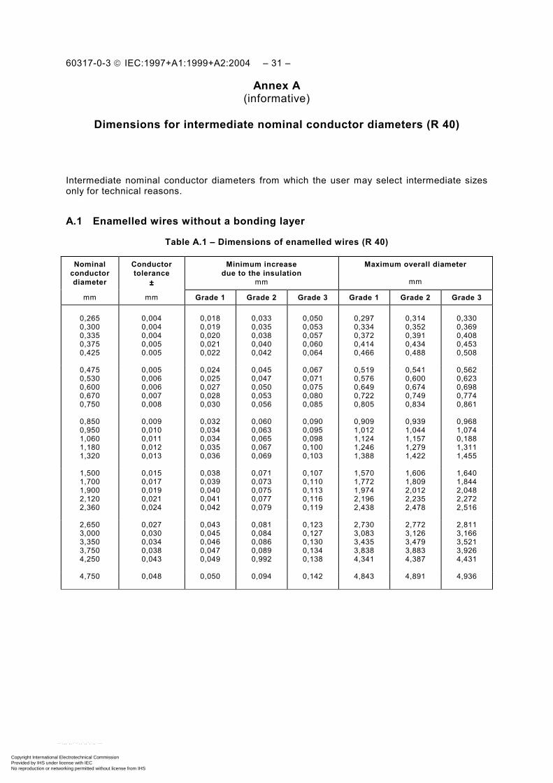
– 30 – 60317-0-3 CEI:1997+A1:1999+A2:2004
Annexe A (informative)
Dimensions pour les diamètres nominaux des conducteurs
intermédiaires (R 40)
Diamètres nominaux des conducteurs intermédiaires qui peuvent être choisis par l'utilisateur pour des raisons techniques.
A.1 Fils émaillés sans couche adhérente
Tableau A.1 – Dimensions pour les fils émaillés (R 40)
Diamètre nominal du conducteur
Tolérance du conducteur
±±±±
Accroissement minimal dû à l'isolant
mm
Diamètre extérieur maximal
mm
mm mm Grade 1 Grade 2 Grade 3 Grade 1 Grade 2 Grade 3
0,265 0,300 0,335 0,375 0,425
0,004 0,004 0,004 0,005 0.005
0,018 0,019 0,020 0,021 0,022
0,033 0,035 0,038 0,040 0,042
0,050 0,053 0,057 0,060 0,064
0,297 0,334 0,372 0,414 0,466
0,314 0,352 0,391 0,434 0,488
0,330 0,369 0,408 0,453 0,508
0,475 0,530 0,600 0,670 0,750
0,005 0,006 0,006 0,007 0,008
0,024 0,025 0,027 0,028 0,030
0,045 0,047 0,050 0,053 0,056
0,067 0,071 0,075 0,080 0,085
0,519 0,576 0,649 0,722 0,805
0,541 0,600 0,674 0,749 0,834
0,562 0,623 0,698 0,774 0,861
0,850 0,950 1,060 1,180 1,320
0,009 0,010 0,011 0,012 0,013
0,032 0,034 0,034 0,035 0,036
0,060 0,063 0,065 0,067 0,069
0,090 0,095 0,098 0,100 0,103
0,909 1,012 1,124 1,246 1,388
0,939 1,044 1,157 1,279 1,422
0,968 1,074 0,188 1,311 1,455
1,500 1,700 1,900 2,120 2,360
0,015 0,017 0,019 0,021 0,024
0,038 0,039 0,040 0,041 0,042
0,071 0,073 0,075 0,077 0,079
0,107 0,110 0,113 0,116 0,119
1,570 1,772 1,974 2,196 2,438
1,606 1,809 2,012 2,235 2,478
1,640 1,844 2,048 2,272 2,516
2,650 3,000 3,350 3,750 4,250
0,027 0,030 0,034 0,038 0,043
0,043 0,045 0,046 0,047 0,049
0,081 0,084 0,086 0,089 0,992
0,123 0,127 0,130 0,134 0,138
2,730 3,083 3,435 3,838 4,341
2,772 3,126 3,479 3,883 4,387
2,811 3,166 3,521 3,926 4,431
4,750 0,048 0,050 0,094 0,142 4,843 4,891 4,936
Copyright International Electrotechnical Commission Provided by IHS under license with IEC
Not for ResaleNo reproduction or networking permitted without license from IHS
--`,,,`,,-`-`,,`,,`,`,,`---
60317-0-3 IEC:1997+A1:1999+A2:2004 – 31 –
Annex A (informative)
Dimensions for intermediate nominal conductor diameters (R 40)
Intermediate nominal conductor diameters from which the user may select intermediate sizes only for technical reasons.
A.1 Enamelled wires without a bonding layer
Table A.1 – Dimensions of enamelled wires (R 40)
Nominal conductor diameter
Conductor tolerance
±±±±
Minimum increase due to the insulation
mm
Maximum overall diameter
mm
mm mm Grade 1 Grade 2 Grade 3 Grade 1 Grade 2 Grade 3
0,265 0,300 0,335 0,375 0,425
0,004 0,004 0,004 0,005 0.005
0,018 0,019 0,020 0,021 0,022
0,033 0,035 0,038 0,040 0,042
0,050 0,053 0,057 0,060 0,064
0,297 0,334 0,372 0,414 0,466
0,314 0,352 0,391 0,434 0,488
0,330 0,369 0,408 0,453 0,508
0,475 0,530 0,600 0,670 0,750
0,005 0,006 0,006 0,007 0,008
0,024 0,025 0,027 0,028 0,030
0,045 0,047 0,050 0,053 0,056
0,067 0,071 0,075 0,080 0,085
0,519 0,576 0,649 0,722 0,805
0,541 0,600 0,674 0,749 0,834
0,562 0,623 0,698 0,774 0,861
0,850 0,950 1,060 1,180 1,320
0,009 0,010 0,011 0,012 0,013
0,032 0,034 0,034 0,035 0,036
0,060 0,063 0,065 0,067 0,069
0,090 0,095 0,098 0,100 0,103
0,909 1,012 1,124 1,246 1,388
0,939 1,044 1,157 1,279 1,422
0,968 1,074 0,188 1,311 1,455
1,500 1,700 1,900 2,120 2,360
0,015 0,017 0,019 0,021 0,024
0,038 0,039 0,040 0,041 0,042
0,071 0,073 0,075 0,077 0,079
0,107 0,110 0,113 0,116 0,119
1,570 1,772 1,974 2,196 2,438
1,606 1,809 2,012 2,235 2,478
1,640 1,844 2,048 2,272 2,516
2,650 3,000 3,350 3,750 4,250
0,027 0,030 0,034 0,038 0,043
0,043 0,045 0,046 0,047 0,049
0,081 0,084 0,086 0,089 0,992
0,123 0,127 0,130 0,134 0,138
2,730 3,083 3,435 3,838 4,341
2,772 3,126 3,479 3,883 4,387
2,811 3,166 3,521 3,926 4,431
4,750 0,048 0,050 0,094 0,142 4,843 4,891 4,936
Copyright International Electrotechnical Commission Provided by IHS under license with IEC
Not for ResaleNo reproduction or networking permitted without license from IHS
--`,,,`,,-`-`,,`,,`,`,,`---

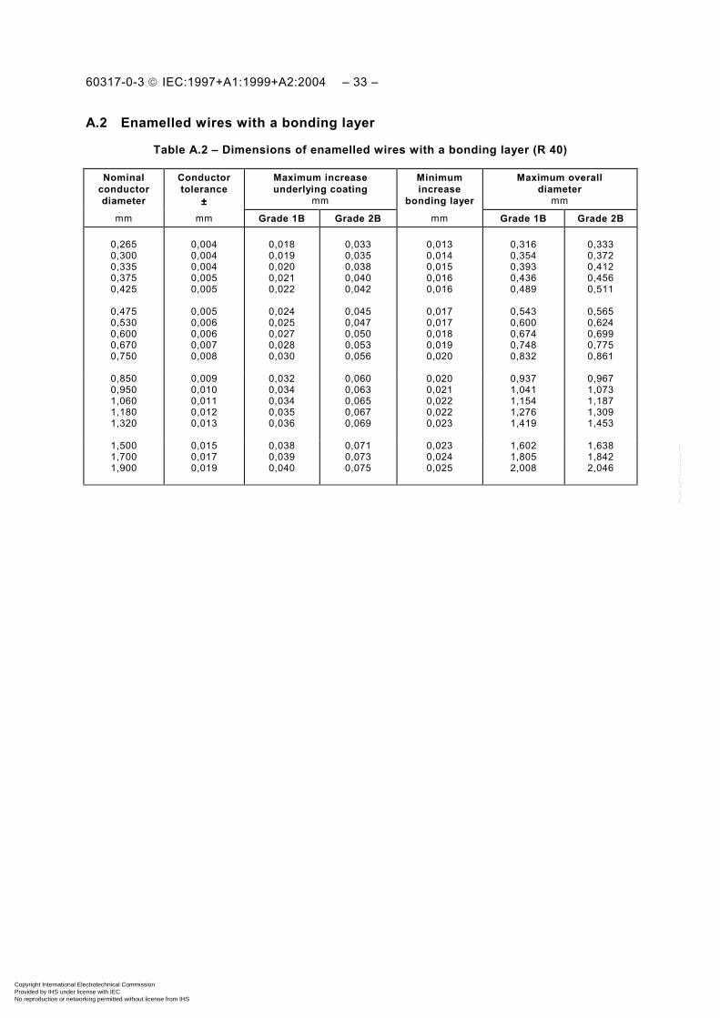
– 32 – 60317-0-3 CEI:1997+A1:1999+A2:2004
A.2 Fils émaillés avec une couche adhérente
Tableau A.2 – Dimensions pour les fils émaillés avec une couche adhérente (R 40)
Diamètre nominal du conducteur
Tolérance du conducteur
±±±±
Accroissement minimal de la sous-couche
mm
Accroissement minimal de la couche adhérente
Diamètre extérieur maximal
mm
mm mm Grade 1B Grade 2B mm Grade 1B Grade 2B
0,265 0,300 0,335 0,375 0,425
0,004 0,004 0,004 0,005 0,005
0,018 0,019 0,020 0,021 0,022
0,033 0,035 0,038 0,040 0,042
0,013 0,014 0,015 0,016 0,016
0,316 0,354 0,393 0,436 0,489
0,333 0,372 0,412 0,456 0,511
0,475 0,530 0,600 0,670 0,750
0,005 0,006 0,006 0,007 0,008
0,024 0,025 0,027 0,028 0,030
0,045 0,047 0,050 0,053 0,056
0,017 0,017 0,018 0,019 0,020
0,543 0,600 0,674 0,748 0,832
0,565 0,624 0,699 0,775 0,861
0,850 0,950 1,060 1,180 1,320
0,009 0,010 0,011 0,012 0,013
0,032 0,034 0,034 0,035 0,036
0,060 0,063 0,065 0,067 0,069
0,020 0,021 0,022 0,022 0,023
0,937 1,041 1,154 1,276 1,419
0,967 1,073 1,187 1,309 1,453
1,500 1,700 1,900
0,015 0,017 0,019
0,038 0,039 0,040
0,071 0,073 0,075
0,023 0,024 0,025
1,602 1,805 2,008
1,638 1,842 2,046
Copyright International Electrotechnical Commission Provided by IHS under license with IEC
Not for ResaleNo reproduction or networking permitted without license from IHS
--`,,,`,,-`-`,,`,,`,`,,`---
60317-0-3 IEC:1997+A1:1999+A2:2004 – 33 –
A.2 Enamelled wires with a bonding layer
Table A.2 – Dimensions of enamelled wires with a bonding layer (R 40)
Nominal conductor diameter
Conductor tolerance
±±±±
Maximum increase underlying coating
mm
Minimum increase
bonding layer
Maximum overall diameter
mm
mm mm Grade 1B Grade 2B mm Grade 1B Grade 2B
0,265 0,300 0,335 0,375 0,425
0,004 0,004 0,004 0,005 0,005
0,018 0,019 0,020 0,021 0,022
0,033 0,035 0,038 0,040 0,042
0,013 0,014 0,015 0,016 0,016
0,316 0,354 0,393 0,436 0,489
0,333 0,372 0,412 0,456 0,511
0,475 0,530 0,600 0,670 0,750
0,005 0,006 0,006 0,007 0,008
0,024 0,025 0,027 0,028 0,030
0,045 0,047 0,050 0,053 0,056
0,017 0,017 0,018 0,019 0,020
0,543 0,600 0,674 0,748 0,832
0,565 0,624 0,699 0,775 0,861
0,850 0,950 1,060 1,180 1,320
0,009 0,010 0,011 0,012 0,013
0,032 0,034 0,034 0,035 0,036
0,060 0,063 0,065 0,067 0,069
0,020 0,021 0,022 0,022 0,023
0,937 1,041 1,154 1,276 1,419
0,967 1,073 1,187 1,309 1,453
1,500 1,700 1,900
0,015 0,017 0,019
0,038 0,039 0,040
0,071 0,073 0,075
0,023 0,024 0,025
1,602 1,805 2,008
1,638 1,842 2,046
Copyright International Electrotechnical Commission Provided by IHS under license with IEC
Not for ResaleNo reproduction or networking permitted without license from IHS
--`,,,`,,-`-`,,`,,`,`,,`---

– 34 – 60317-0-3 CEI:1997+A1:1999+A2:2004
Annexe B (Supprimée)
Copyright International Electrotechnical Commission Provided by IHS under license with IEC
Not for ResaleNo reproduction or networking permitted without license from IHS
--`,,,`,,-`-`,,`,,`,`,,`---

60317-0-3 IEC:1997+A1:1999+A2:2004 – 35 –
Annex B (Deleted)
Copyright International Electrotechnical Commission Provided by IHS under license with IEC
Not for ResaleNo reproduction or networking permitted without license from IHS
--`,,,`,,-`-`,,`,,`,`,,`---

– 36 – 60317-0-3 CEI:1997+A1:1999+A2:2004
Annexe C (informative)
Méthode pour le calcul de la résistance linéique
Les valeurs extrêmes de la résistance électrique sont calculées sur les bases suivantes:
C.1 Pour diamètres nominaux des conducteurs jusqu'à et y compris 1,000 mm
Les valeurs minimale et maximale de la résistance sont calculées respectivement à partir des valeurs minimale et maximale de la résistivité en tenant compte pour chaque diamètre du conducteur de la tolérance dimensionnelle sur ce diamètre.
La résistance linéique est calculée à partir de:
R qmin min max1= × −ρ (Ω m–1)
R qmax max min1= × −ρ (Ω m–1)
où
ρmin = 1/36,2 Ω mm2 m–1;
ρmax = 1/35,5 Ω mm2 m–1;
q est la section droite du conducteur en millimètres carrés.
Copyright International Electrotechnical Commission Provided by IHS under license with IEC
Not for ResaleNo reproduction or networking permitted without license from IHS
--`,,,`,,-`-`,,`,,`,`,,`---

60317-0-3 IEC:1997+A1:1999+A2:2004 – 37 –
Annex C (informative)
Method for the calculation of linear resistance
The limits of electrical resistance are calculated on the following basis:
C.1 For nominal conductor diameters up to and including 1,000 mm
The minimum and the maximum values of resistance are calculated from the minimum and maximum values of the resistivity by taking into account for each conductor diameter the relevant dimensional tolerance.
The linear resistance is calculated from:
R qmin min max1= × −ρ (Ω m–1)
R qmax max min1= × −ρ (Ω m–1)
where
ρmin = 1/36,2 Ω mm2 m–1;
ρmax = 1/35,5 Ω mm2 m–1;
q is the cross-section of the conductor in square millimetres.
Copyright International Electrotechnical Commission Provided by IHS under license with IEC
Not for ResaleNo reproduction or networking permitted without license from IHS
--`,,,`,,-`-`,,`,,`,`,,`---

– 38 – 60317-0-3 CEI:1997+A1:1999+A2:2004
Annexe D (informative)
Résistance
Les valeurs de la résistance nominale indiquées dans le tableau suivant sont données uniquement à titre d'information et sont calculées sur le diamètre nominal du conducteur avec une résistivité nominale de 1/35,85 Ω mm2 m-1.
Les valeurs minimale et maximale de la résistance pour les diamètres nominaux des conducteurs jusqu'à et y compris 1,000 mm sont dérivées de calculs effectués conformément à l'annexe C.
Tableau D.1 – Résistances électriques
Diamètre nominal du conducteur
Résistance
Ω/m
Diamètre nominal du conducteur
Résistance nominale
mm Minimale Nominale Maximale mm Ω/mm
0,250 0,280 0,315 0,355 0,400
0,5452 0,4361 0,3456 0,2729 0,2144
0,5683 0,4530 0,3579 0,2818 0,2220
0,5927 0,4708 0,3708 0,2911 0,2299
1,120 1,250 1,400 1,600 1,800
0,02831 0,02273 0,01812 0,01387 0,01096
0,450 0,500 0,560 0,630 0,710
0,1699 0,1379 0,1098 0,08695 0,06842
0,1754 0,1421 0,1133 0,08948 0,07045
0,1811 0,1464 0,1169 0,09211 0,07257
2,000 2,240 2,500 2,800 3,150
0,008879 0,007078 0,005683 0,004530 0,003579
0,800 0,900 1,000
0,05387 0,04257 0,03448
0,05549 0,04385 0,03552
0,05718 0,04518 0,03659
3,550 4,000 4,500 5,000
0,002818 0,002220 0,001754 0,001421
Copyright International Electrotechnical Commission Provided by IHS under license with IEC
Not for ResaleNo reproduction or networking permitted without license from IHS
--`,,,`,,-`-`,,`,,`,`,,`---

60317-0-3 IEC:1997+A1:1999+A2:2004 – 39 –
Annex D (informative)
Resistance
The figures for nominal resistance are given for information only. They are calculated on the basis of the nominal conductor diameter and a nominal resistivity of 1/35,85 Ω mm2 m-1.
The minimum and maximum resistance figures for nominal conductor diameter up to and including 1,000 mm are derived from calculations made according to annex C.
Table D.1 – Electrical resistances
Nominal conductor diameter
Resistance
Ω/m
Nominal conductor diameter
Nominal resistance
mm Minimum Nominal Maximum mm Ω/mm
0,250 0,280 0,315 0,355 0,400
0,5452 0,4361 0,3456 0,2729 0,2144
0,5683 0,4530 0,3579 0,2818 0,2220
0,5927 0,4708 0,3708 0,2911 0,2299
1,120 1,250 1,400 1,600 1,800
0,02831 0,02273 0,01812 0,01387 0,01096
0,450 0,500 0,560 0,630 0,710
0,1699 0,1379 0,1098 0,08695 0,06842
0,1754 0,1421 0,1133 0,08948 0,07045
0,1811 0,1464 0,1169 0,09211 0,07257
2,000 2,240 2,500 2,800 3,150
0,008879 0,007078 0,005683 0,004530 0,003579
0,800 0,900 1,000
0,05387 0,04257 0,03448
0,05549 0,04385 0,03552
0,05718 0,04518 0,03659
3,550 4,000 4,500 5,000
0,002818 0,002220 0,001754 0,001421
Copyright International Electrotechnical Commission Provided by IHS under license with IEC
Not for ResaleNo reproduction or networking permitted without license from IHS
--`,,,`,,-`-`,,`,,`,`,,`---

– 40 – 60317-0-3 CEI:1997+A1:1999+A2:2004
Annexe E (informative)
Essai de défaillance à haute température
Aucune exigence n'est prescrite.
Pour la méthode d'essai, consulter l'annexe A de la CEI 60851-6.
___________
Copyright International Electrotechnical Commission Provided by IHS under license with IEC
Not for ResaleNo reproduction or networking permitted without license from IHS
--`,,,`,,-`-`,,`,,`,`,,`---

60317-0-3 IEC:1997+A1:1999+A2:2004 – 41 –
Annex E (informative)
High temperature failure test
No requirements are specified.
For test method see annex A of IEC 60851-6.
___________
Copyright International Electrotechnical Commission Provided by IHS under license with IEC
Not for ResaleNo reproduction or networking permitted without license from IHS
--`,,,`,,-`-`,,`,,`,`,,`---

Copyright International Electrotechnical Commission Provided by IHS under license with IEC
Not for ResaleNo reproduction or networking permitted without license from IHS
--`,,,`,,-`-`,,`,,`,`,,`---

Standards Survey
The IEC would like to offer you the best quality standards possible. To make sure that wecontinue to meet your needs, your feedback is essential. Would you please take a minuteto answer the questions overleaf and fax them to us at +41 22 919 03 00 or mail them tothe address below. Thank you!
Customer Service Centre (CSC)
International Electrotechnical Commission3, rue de Varembé1211 Genève 20Switzerland
or
Fax to: IEC/CSC at +41 22 919 03 00
Thank you for your contribution to the standards-making process.
Non affrancareNo stamp required
Nicht frankierenNe pas affranchir
A Prioritaire
RÉPONSE PAYÉE
SUISSE
Customer Service Centre (CSC)International Electrotechnical Commission3, rue de Varembé1211 GENEVA 20Switzerland
Copyright International Electrotechnical Commission Provided by IHS under license with IEC
Not for ResaleNo reproduction or networking permitted without license from IHS
--`,,,`,,-`-`,,`,,`,`,,`---

Q1 Please report on ONE STANDARD andONE STANDARD ONLY . Enter the exactnumber of the standard: (e.g. 60601-1-1)
.............................................................
Q2 Please tell us in what capacity(ies) youbought the standard (tick all that apply).I am the/a:
purchasing agent R
librarian R
researcher R
design engineer R
safety engineer R
testing engineer R
marketing specialist R
other.....................................................
Q3 I work for/in/as a:(tick all that apply)
manufacturing R
consultant R
government R
test/certification facility R
public utility R
education R
military R
other.....................................................
Q4 This standard will be used for:(tick all that apply)
general reference R
product research R
product design/development R
specifications R
tenders R
quality assessment R
certification R
technical documentation R
thesis R
manufacturing R
other.....................................................
Q5 This standard meets my needs:(tick one)
not at all R
nearly R
fairly well R
exactly R
Q6 If you ticked NOT AT ALL in Question 5the reason is: (tick all that apply)
standard is out of date R
standard is incomplete R
standard is too academic R
standard is too superficial R
title is misleading R
I made the wrong choice R
other ....................................................
Q7 Please assess the standard in thefollowing categories, usingthe numbers:(1) unacceptable,(2) below average,(3) average,(4) above average,(5) exceptional,(6) not applicable
timeliness .............................................quality of writing....................................technical contents.................................logic of arrangement of contents ..........tables, charts, graphs, figures ...............other ....................................................
Q8 I read/use the: (tick one)
French text only R
English text only R
both English and French texts R
Q9 Please share any comment on anyaspect of the IEC that you would likeus to know:
............................................................
............................................................
............................................................
............................................................
............................................................
............................................................
............................................................
............................................................
............................................................
............................................................
............................................................
............................................................
Copyright International Electrotechnical Commission Provided by IHS under license with IEC
Not for ResaleNo reproduction or networking permitted without license from IHS
--`,,,`,,-`-`,,`,,`,`,,`---

Enquête sur les normes
La CEI ambitionne de vous offrir les meilleures normes possibles. Pour nous assurerque nous continuons à répondre à votre attente, nous avons besoin de quelquesrenseignements de votre part. Nous vous demandons simplement de consacrer un instantpour répondre au questionnaire ci-après et de nous le retourner par fax au+41 22 919 03 00 ou par courrier à l’adresse ci-dessous. Merci !
Centre du Service Clientèle (CSC)
Commission Electrotechnique Internationale3, rue de Varembé1211 Genève 20Suisse
ou
Télécopie: CEI/CSC +41 22 919 03 00
Nous vous remercions de la contribution que vous voudrez bien apporter ainsià la Normalisation Internationale.
Non affrancareNo stamp required
Nicht frankierenNe pas affranchir
A Prioritaire
RÉPONSE PAYÉE
SUISSE
Centre du Service Clientèle (CSC)Commission Electrotechnique Internationale3, rue de Varembé1211 GENÈVE 20Suisse
Copyright International Electrotechnical Commission Provided by IHS under license with IEC
Not for ResaleNo reproduction or networking permitted without license from IHS
--`,,,`,,-`-`,,`,,`,`,,`---

Q1 Veuillez ne mentionner qu’UNE SEULENORME et indiquer son numéro exact:(ex. 60601-1-1)
.............................................................
Q2 En tant qu’acheteur de cette norme,quelle est votre fonction?(cochez tout ce qui convient)Je suis le/un:
agent d’un service d’achat R
bibliothécaire R
chercheur R
ingénieur concepteur R
ingénieur sécurité R
ingénieur d’essais R
spécialiste en marketing R
autre(s).................................................
Q3 Je travaille:(cochez tout ce qui convient)
dans l’industrie R
comme consultant R
pour un gouvernement R
pour un organisme d’essais/ certification R
dans un service public R
dans l’enseignement R
comme militaire R
autre(s).................................................
Q4 Cette norme sera utilisée pour/comme(cochez tout ce qui convient)
ouvrage de référence R
une recherche de produit R
une étude/développement de produit R
des spécifications R
des soumissions R
une évaluation de la qualité R
une certification R
une documentation technique R
une thèse R
la fabrication R
autre(s).................................................
Q5 Cette norme répond-elle à vos besoins:(une seule réponse)
pas du tout R
à peu près R
assez bien R
parfaitement R
Q6 Si vous avez répondu PAS DU TOUT àQ5, c’est pour la/les raison(s) suivantes:(cochez tout ce qui convient)
la norme a besoin d’être révisée R
la norme est incomplète R
la norme est trop théorique R
la norme est trop superficielle R
le titre est équivoque R
je n’ai pas fait le bon choix R
autre(s) ................................................
Q7 Veuillez évaluer chacun des critères ci-dessous en utilisant les chiffres(1) inacceptable,(2) au-dessous de la moyenne,(3) moyen,(4) au-dessus de la moyenne,(5) exceptionnel,(6) sans objet
publication en temps opportun ..............qualité de la rédaction...........................contenu technique ................................disposition logique du contenu ..............tableaux, diagrammes, graphiques, figures ................................................autre(s) ................................................
Q8 Je lis/utilise: (une seule réponse)
uniquement le texte français R
uniquement le texte anglais R
les textes anglais et français R
Q9 Veuillez nous faire part de vosobservations éventuelles sur la CEI:
............................................................
............................................................
............................................................
............................................................
............................................................
............................................................
Copyright International Electrotechnical Commission Provided by IHS under license with IEC
Not for ResaleNo reproduction or networking permitted without license from IHS
--`,,,`,,-`-`,,`,,`,`,,`---

Copyright International Electrotechnical Commission Provided by IHS under license with IEC
Not for ResaleNo reproduction or networking permitted without license from IHS
--`,,,`,,-`-`,,`,,`,`,,`---

ISBN 2-8318-7717-2
-:HSMINB=]\\V\Y:ICS 29.060.10
Typeset and printed by the IEC Central Office GENEVA, SWITZERLAND
Copyright International Electrotechnical Commission Provided by IHS under license with IEC
Not for ResaleNo reproduction or networking permitted without license from IHS
--`,,,`,,-`-`,,`,,`,`,,`---