paradigm shift geometric accuracy · cctt qqaa image performance ctp401 ctp515 ctp445 ctp528 ctp486...
TRANSCRIPT

QA FOR IMAGING SYSTEMS USEDQA FOR IMAGING SYSTEMS USEDFOR PLANNING (CT, PET, MR)FOR PLANNING (CT, PET, MR)
Sasa MuticSasa Mutic
Department of Radiation OncologyDepartment of Radiation OncologySiteman Cancer CenterSiteman Cancer Center
Mallinckrodt Institute of RadiologyMallinckrodt Institute of RadiologyWashington University School of MedicineWashington University School of Medicine
St. Louis, Missouri 63110St. Louis, Missouri 63110
Outl ineOutlin e•• Image Quality Concerns for RTImage Quality Concerns for RT•• Acceptanc eAcceptance vsvs Conti nuing QAContinuing QA•• Selecti on of QA tasksSelectio n of QA tasks•• Divis ion of LaborDivision of Labor•• Proc edure speci fic proces sesProcedure specif ic processes
–– FusionFusion–– CTCT–– MRIMRI–– PETPET
•• Concl usionsConc lusions
Paradigm ShiftParadigm Shift
•• Imaging equipment in the past wasImaging equipment in the past wasdesigned for diagnostic radiolog y anddesigned for diag nostic radiolog y andthen modified for radio therapythen modif ied for radiothera py
•• There are new CT scanners that areThere are new CT scanners that arespeci fical ly designed for radiothera pyspecifically designed for radiothera py
•• Or they have special features that areOr they have special featur es that aredesigned for radiother apydesigned for radiother apy
•• PET/CT scan ners are also desi gnedPET/CT scanners are also des ign edwith RT scanning conce rns inwith RT scanning conc erns in mondmond
Geometric Acc uracyGeometric Acc uracy
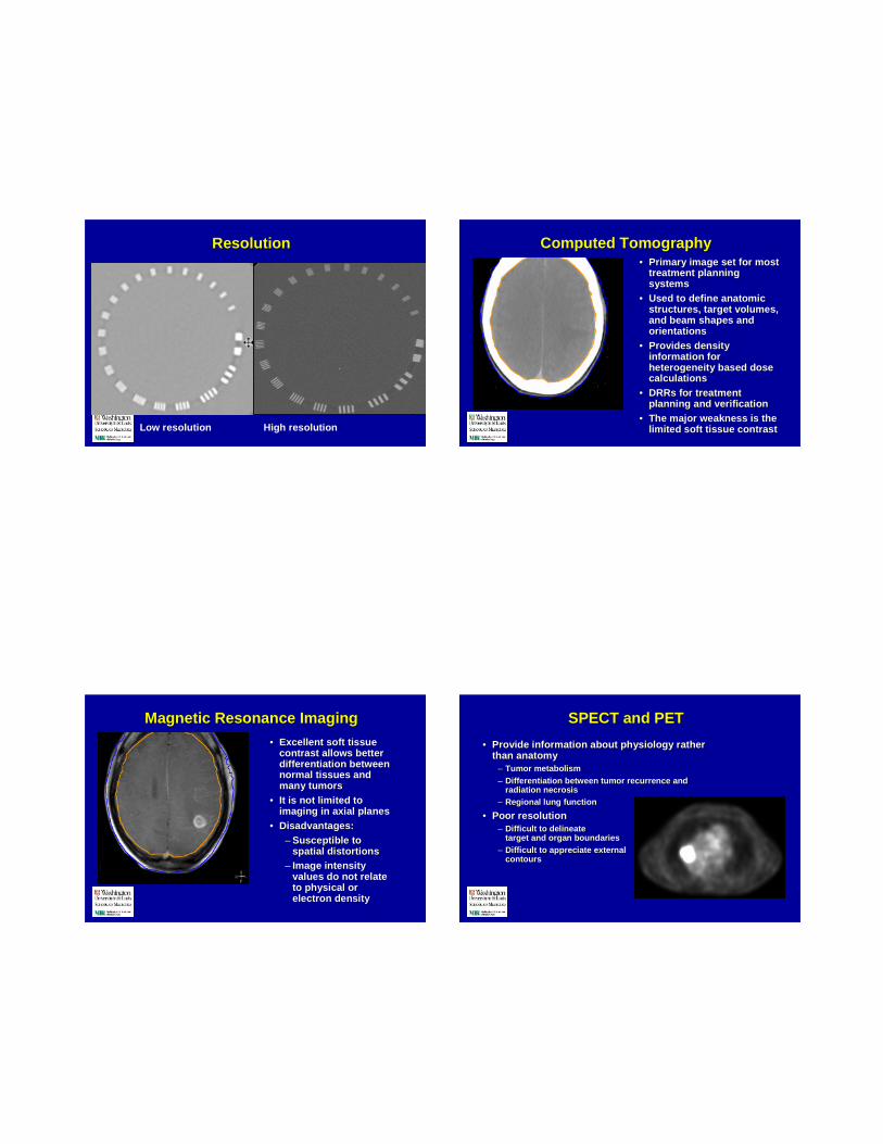
Resolu tionResolut ion
Low resolu tion High resolution
Comput ed Tomograph yComput ed Tomograph y•• Prima ry image set for mostPrimary image set for most
treatment planningtrea tment planningsystemssystem s
•• Used to define anatom icUsed to define anatom icstruct ures , target volumes,stru ctures, target volumes,and beam shape s andand beam shape s andorientat ionsor ientati ons
•• Provides dens ityProvi des densityinformation forinformati on forheteroge neity based doseheterogenei ty based dosecalculat ionscalcul ations
•• DRRs for trea tmentDRRs for trea tmentplann ing and verificationplanni ng and verification
•• The major weakness is theThe major weakness is thelimited soft tis sue contrastlimited soft tis sue contrast
Magnet ic Resonance ImagingMagnet ic Resonance Imaging
•• Excel lent so ft tissueExcellent soft tissuecontrast allow s bettercontrast allows betterdiffe rentiati on betweendifferentia tion betweennormal tissues andnormal tissues andmany tumorsmany tumors
•• It is no t limited toIt is not limi ted toimaging in axia l planesimaging in axi al planes
•• Disadv antages:Disad vantages :–– Susceptible toSusce ptible to
spatia l di storti onsspati al distortions–– Image intens ityImage intensity
values do not relatevalues do not relateto phy si cal orto phys ical orelectr on dens ityelectron density
SPECT and PETSPECT and PET
•• Provide info rmation about phys io logy ratherProvi de informatio n about ph ysiology ratherthan anatomythan anatomy
–– Tumo r metabo lismTumor metabolism
–– Differen tiat ion betw een tumor recurr ence andDifferen tiat ion between tumor recur rence andradiation necr osisradiati on necrosis
–– Regional lung funct ionRegiona l lun g functio n
•• Poor resolutionPoor resolu tion–– Difficult to delineat eDifficult to delineat e
target and organ boun dariestarget and organ bou ndaries–– Difficult to appr eciate externalDifficult to appre ciat e extern al
contourscontou rs

CT simulatorCT simulator•• CT scanner withCT scanner with
external lasersexternal lasers•• Flat tablet opFlat tablet op•• VirtualVirtual
simulationsimulationsoftwaresoftware
Panorama 0.23T R/TPanorama 0.23T R/T
Laser bridge Spacers allow easyPositioning of RF coils
Flat table topinsert
High Field MagnetHigh Field Magnet
•• 1.5 T1.5 Tsupercond uctingsuperconducting
•• Closed boreClosed bore•• Flat couch insertFlat couch insert
addedadded•• House d inHouse d in
radio logy, FCCCradio logy, FCCC
Courtesy Dennis Mah
PET/CT scanner comb ined unitPET/CT scanner combi ned unit•• Multisl ice CTMulti sli ce CT
scanne r mated to ascanne r mated to aPET scannerPET scanner
•• Possibly thre e scansPossi bly three scansacquire d duringacqui red duri ngpro cedu reprocedure
–– AttenuationAttenu ationcorr ecti on CTcor rection CT
–– PETPET–– TreatmentTreatment
plannin g CT, withplanning CT, withcon trast ifcontrast ifnecessarynecessa ry

Adaptiv e TherapyAdapt ive TherapyOnboard volumetric imaging MRMR--Guid edGuid ed
Viewray Renaissanc e
CT Time LineCT Time Line
85 89 92 94 98 00 01 02 04
Slip Ring
HelicalScann ing
Dual sli ceScanning
Commercia lCT-simulator
4-sli ce0.5 sec
LargeBore SS
8-sl ice0.5 sec
16 slicesub 0.5
64 sli ce
LargeBore MS
CT Simulator Evalu ationCT Simulator Evaluation
•• TaskTask–– Radiation andRadiati on and
patient safetypatient safety–– CT dosime tr yCT dosimetry–– Evaluati on ofEvaluati on of
electro mechanicalelectromec hani calcomponentscomponents
–– Evaluati on of imageEvaluati on of imagequalityquality
•• Solu tion?Solution?–– AAPM reportAAPM repo rt
numb er 39,num ber 39,–– AAPM TG53 reportAAPM TG53 report–– AAPM TG66 reportAAPM TG66 report

Imaging QA in Radiation TherapyImaging QA in Radiation Therapy
•• TasksTasks–– Patient safetyPatien t safety–– Image performance evalua tionImage performa nce evaluation–– Evaluation of electromec hanicalEvalu ation of electromechanical
compo nentscomponents–– Proces s evaluationProcess evaluation –– data transfe r, imagedata transfe r, image
registration, image usage, etc.registr ation, im age usage, etc.•• Scanne r location and prim ary purpo seScanner location and primary purpose
–– Diagn osticDiagnostic vsvs radiatio n therapy goalsradiation therapy goals–– Anato mic al and biolo gical imagingAnatomica l and biologic al imaging
Common QA TasksCommon QA Tasks
•• Signa l to Noise ratioSignal to Noise ratio•• Image Uniformi tyImage Uniformity•• Spatia l LinearitySpatial Line arity•• HighHigh --ContrastContrast
Spatia l Resolutio nSpatial Resolution•• Slice Thick nessSlice Thick ness•• SliceSlice
Positi on/SeparationPosition/Se par ation•• Image ArtifactsImage Artifacts
•• Laser Al ignmentLaser Al ignme nt•• Couch Alignme ntCouch Al ignment•• Quanti tativ eQuant itative
Image Qual ity Ind icatorsImage Qual ity Ind icators
•• Quantitativ eQuantitati ve–– Phantom MeasurementsPhantom Measurem ents
»» High ContrastHigh Contrast»» Low ContrastLow Contras t»» UniformityUniformity»» Spatial Integri tySpatial Integrity»» Ar ti factsArti facts»» Slice thicknessSlice thi ckness»» Quantitati ve accurac yQuanti tative accura cy
•• QualitativeQualitative–– Physici an Prefer encesPhysic ian Preferen ces
»» TumorTumor»» Normal Structur esNormal Struc tures»» DRR/DCR ObjectsDRR/DCR Objects»» Work flowWorkfl ow»» Customized protocolsCustomized proto cols
QA in Radiation TherapyQA in Radiation Therapy
•• Commission ing and establis hment of baselin eCommissi oning and establishm ent of baselineperformanceperformance
•• Perio dic quali ty assuranc ePeriodic quality assurance–– DailyDaily –– Perhaps the most importa ntPerhaps the most imp ortan t–– MonthlyMonthly–– AnnualAnnual
•• Patien t specific QAPatien t speci fic QA•• Process QAProces s QA•• QA GoalsQA Goals

Commissioni ng and establis hmentCommi ss ioni ng and establis hmentof baseline performanceof baseline performance
•• Verifica tion of scannerVerifica tion of scannerperformanceper formance
•• Establ ishme nt ofEstabl ishme nt ofbaselin e databaselin e data
•• Verifica tion ofVerifica tion ofmanufact urer phantomsmanufact urer phantomsand image analysis toolsand image anal ysis tools
•• Establ ishme nt of imagingEstabl ishme nt of imagingprotocolsprotocols –– usingusingphanto ms to unders tandphanto ms to understanddifferen cesdifferen ces
Manufacturerphanto m
Third -partyphanto m
CT QACT QA
Image PerformanceImage Performance
CTP401 CTP515
CTP486CTP528CTP445
Catphan 500
Resolut ion (High Contra st)Resolut ion (High Contra st)
•• Ability of the systemAbility of the systemto record separa teto record separa teimages of smal limages of smal lobjects that areobjects that areplaced very closeplaced very closetoget hertogether

Subject Contrast (Low Contrast)Subject Contrast (Low Contrast)
•• Ability of a syste mAbility of a systemto resolve adjac entto resolve adjace ntobjec ts with smallobjec ts with smalldensity differe ncesdens ity differ ences
•• Noise limitedNoise limited
Unif ormit y and NoiseUnif ormity and Noise
Measure Daily
True vs. Extra polated FOVTrue vs. Extra polated FOV
From impactscan.o rg repo rt 05071
Evaluation of Extrapolated FOVEvaluation of Extrapolated FOV
From impact scan.or g report 05071

Radiation and Patient safetyRadiation and Patient safety
•• Patient SafetyPatient Safety–– InterlocksInterlocks
–– ElectromechanicalElectr omechanical–– Door Inter lockDoor Interlock–– CTDICTDI
»» Definitio nDefin itio n»» Multislice CTMul tis lice CT
•• Radiat ion SafetyRadiation Safety–– Workloa dWorkload –– potential pitf allpotential pitfall
»» Significant increas eSignificant incr ease»» Shield ing desi gnShielding design»» NCRP 147NCRP 147»» Radiatio n surveyRadiation survey
Elect romechanical Compon entsElect romechanical Compon ents
•• XX--ray Generatorray Genera tor•• Gantry Alignme ntGantry Al ignme nt•• Table Alignment/Acc urac yTable Al ignme nt/Accuracy•• Laser Alignment/AccuracyLaser Alignment/Accurac y
Electrome chanic al ComponentsElectrome chanic al Componentsxx--ray Generatorray Generator
•• Need a nonNeed a non --invasiveinvasivemetermeter
–– kV accu racykV accuracy–– Timer accuracyTimer accuracy–– mAmA lineari tylinearity–– HVLHVL
measureme ntsmeasuremen ts
CT Simula tor MechanicalCT Simula tor Mechanical AlignemntAlignemnt

Electrome chanic al ComponentsElectrome chanic al ComponentsGantr y Alignment/Accurac yGantr y Alignment/Accurac y
•• Gantry tilt accuracyGantry tilt accuracy•• Gantry verticalGantry vertical
–– Imaging planeImaging planeorthogonal to the couchorthogonal to the cou chtoptop
•• Gantry verticalGantry verticalplacementplacementreprodu cibilityreprodu cibility
–– Especiall y important forEspecial ly important fordual pur pose scanner sdual pur pose scanners
Elect romechanical Compon entsElect romechanical Compon entsTable Alignment/ Accu racyTable Alignment /Accu racy
•• Tested with weightTested with weight–– SettleSettle–– SagSag
•• Tabletop motionTabletop moti onorthogonal/par allel withortho gonal/para llel withthe imaging planethe imaging plane
•• Table positiona lTable pos iti onalaccu racy/r epr oduci bilityaccuracy/re pr oducibility
–– VerticalVert ical–– LongitudinalLongitudinal
Elect rome chanical Compone ntsElect rome chanical ComponentsLaser Alignment/AccuracyLaser Alignment/Accuracy
•• Lasers orthogonal/parallelLasers ort hogonal/parallelwith the imaging planewith the imaging plane
•• Lasers spacingLasers spacin g•• Laser position al accurac yLaser positional accura cy
–– AbsoluteAbsolute–– LinearityLinearity–– Reproducibi lityReproducibility
•• Coord inate systemCoordinate systemor ientationorienta tion
MR QAMR QA

MR QA TasksMR QA Tasks
•• Signal to Noise ratioSignal to Noise ratio•• Image UniformityImage Uniformity•• Spatia l LinearitySpat ial Lineari ty•• HighHigh --Contra st Spatial ResolutionCont rast Spatia l Resolution•• Slice ThicknessSlice Thickn ess•• Slice Position/SeparationSlice Posi tion/Separation•• Image Arti factsImage Art ifacts
AAPM Report #28, Med Phys 17, 1990
MR Spatial DistortionsMR Spatial Distortions
•• Inhomoge neityInhomoge neity of main magnetic fieldof main magnetic field•• Nonlineari ties of the spatially encodingNonli nearitie s of the spati ally encodin g
gradient magnetic fieldsgradi ent magnetic field s•• Alterat ion of magnetic field s by imagedAlterati on of magnetic fields by imaged
objectsobjects
Disadvantage of MRIDisadvantage of MRI SimSim :: Distort ionDistortion
•• Bigge r patie nts canBigge r patie nts canproduc e signific antproduce signifi cantdistortionsdistortions
•• Patient was >300 lbsPatient was >300 lbs
Courtesy Dennis Mah
Gradient Distortion CorrectionGradient Distortio n Correction•• Desig n tradeDesign trade --offs limit lineari ty of gradien tsoffs limi t linearity of gradients
–– Can improve lineari ty, bu t at loss ofCan imp rove linearity , but at los s ofperformanceperf orman ce
•• System is optimize d based upon designSystem is opti mized based upon designtradetrade --offsoffs
•• Compute gradient magnetic field fromComput e gr adient magnetic field fromengi neering diagramsenginee ri ng diagrams
•• Derive corre ction terms for theoret icallyDerive correc tion terms for theoret icallypredic ted magnetic fieldpredict ed magneti c field
•• Mathematical ly correct the MR images usin gMathemati call y correct the MR images usin gcorrection factorscorrect ion factors
Courtesy Dennis Mah

PhantomPhantom
Courtesy Dennis Mah
GDCGDC –– Gradient Distortion CorrectionGradient Distortion Correction
Axial Sagittal CoronalCourtesy Philips Medical Systems,Inc.
IsoIso --Error MapError Map
BeforeGDC
Courtesy Denni s Mah
IsoIso Error MapError Map
With GDC
Courte sy Denni s Mah

Image Distortion Away fromImage Distortion Away from IsocenterIsocenter
Courtesy Dennis Mah
Distort ion CorrectionsDistort ion Corrections
Courtes y Dennis Mah
––QA PhantomQA Phantom––ForFor
evaluatingevaluatinglasers withlasers withMRMR SimSim
•• Image distortionImage distortionevaluationevaluationphantomphantom
–– The phantom andThe phantom andSW is intendedSW is intendedfor evalua tion offor evaluation ofresidua lresidualgeometricalgeometrica ldistortions indis tortio ns inimages .images.
Courtes y Dennis Mah

PET QAPET QA
Quality Assurance in PETQuality Assurance in PET
•• Whether the camera is a dedic ated PET camera or a combinedWheth er the camera is a dedicated PET camer a or a combi nedPET/CT camer a, the first step for image quality is the detectorPET/CT camera, the first step for image quality is the detectorsetup .setu p.
•• Most PET detectors are composed of detector modules made ofMost PET detectors are compose d of detector modules made ofscintil latorscintillat or block and an array of 4block and an array of 4 PMTsPMTs..
•• The setup of those block for pro per operatio ns includes theThe setup of those block for prop er oper ations includes theadjustments of:adju stments of:
–– Constant Fract ion Discrimina tor (CFD)Constant Fraction Disc rimin ator (CFD)–– Timing alignmentsTiming alignmen ts–– XY profilesXY profiles–– Energy Calibrati onEnergy Calibration–– Look up tabl e for cryst al boun dary identificat ion.Look up table for crys tal bou ndary identi fication .
This step is called the block setup procedure
Courtesy Rich ard Laforest
Detector ModuleDetector Module
• Small crystals for high resolution
• Small Gaps for high sensitivity
• Large tubes for fast, stable timing
• Light sharing scheme for positionencoding
• Lower cost, better reliability thanindividual crystals, small tubes.
Courtesy Richar d Lafo rest
Normalizati onNormalizati on
•• Every pai r of detector does not have exactly the sameEvery pair of detector does not have exactly the samedetect ion effi ciency.detecti on effic iency.
•• The fluctuati ons in detectio n efficiency from theThe fluctua tions in detection effic iency fro m thedifferen t lines of response is comp ensated by thediff erent lines of respo nse is compen sated by thenormalization procedure in which a unif orm sour ce ofnormalization pro cedure in which a uniform source ofactivity is used to measure the intrinsic detect ionact ivit y is used to measur e the intrinsic detect ioneffic iency for each line of response and the resu ltingeffici ency for each lin e of response and the resultin gnormalization file is kept on the compu ter memory.normalization fi le is kept on the comp uter memory.
Courtesy Rich ard Laforest

Position EncodingPosition Encoding
•• Flood hi stogra m slightly distorte d.Flood hi stogram slightly distorted.•• Use lookUse loo k--up tabl e (LUT) to identify the crystalup table (LUT) to identif y the crystal
numb er struck.num ber struck.
SUV CalibrationSUV Calibration
•• Absol uteAbsolute Quanti tationQuant itati on is importa nt in PET as it allows tois important in PET as it allows toextract the activ ity concentration in eachextract the activi ty concentration in each voxelvoxel ..
•• Performed using a crossPerformed using a cross --calib rat ion uni form cylind ercalibrati on uniform cylinde rcontain ing a know amount of radiocontai ning a know amoun t of radio --activi ty, most likely aactiv ity, most likely auniform Geuniform Ge--68 cyli nder or a68 cyl inder or a fillablefillab le FF--18 cyli nder.18 cyl inder.
PET Quali ty ControlPET Quali ty Control
•• Qual ity control in ensure on a daily basis by performing aQuality control in ensure on a daily basis by perform ing ablank transmissio n scan (on a dedicated PET scan nerblank transmissi on scan (on a dedicated PET scannerequippe d with Transm ission rods) and compared with aequippe d with Transmission rods) and compared with astandard blank (one acquir ed immediately after detecto rstandard blank (one acquire d immediately after detect orsetup).setup).
•• Inspec tion of si nograms to identify missing blocks orInspec tion of sinograms to identify missing blocks orsuspic ious artifacts.suspic ious artifacts.
Schedule for Qualit y AssuranceSchedule for Qualit y Assura nce
•• Detector Setup (every 3 to 6 month s) or anyt ime aDetect or Setup (every 3 to 6 month s) or anytime amaintenance is performed on the scanner.mainten ance is performed on the scann er.
•• Normal izati on and calibra tion following every detecto rNormali zation and cal ibration following every detecto rsetup .setup.
•• Daily inspe ction of sinograms and daily blankDaily inspec tion of sin ogram s and daily blanktransmissi on scan.transmission scan.

IMAGEIMAGEREGISTRATION QAREGISTRATION QA
AAPM TG# 132AAPM TG# 132
Mul tim odali ty Image Fusi onMult imodali ty Image Fusi on
•• Quality AssuranceQuality AssuranceIssues:Issues:
–– Image data integrityImage data integrit yafter transf erafter transf er
–– Image spat ialImage spat ialinteg rityintegrity
–– Image fusionImage fusionaccura cyaccurac y
–– Overall soft wareOverall soft warefunctio nalit yfunctio nalit y
Multimodality Image FusionMultimodality Image Fusion•• Fusion Techni ques:Fusion Techn iques:
–– SurfaceSurface --basedbasedRegistr atio nRegistra tion
»» InternalInternal
»» Exter nalExter nal–– ImageImage --basedbased
Registr atio nRegistra tion–– Poin tPoint --basedbased
Registr atio nRegistra tion–– Automatic andAutomatic and
semiautomati csemiautomaticcomputer assistedcomputer assiste dmethodsmethods
Sterotactic Localizatio n PhantomSterotactic Loca lizatio n Phantom
•• Anthropomorphic head phantomAnthr opomorphic head phantom•• Develope d for assessment of ster eotacticDeveloped for assessment of stereo tactic
loc alization accuracylocal ization accuracy•• Plastic sphere s and rods located throug houtPlasti c spheres and rods locate d throug hout
the phantomthe phantom•• Coordi nates of poin ts within spheres and rodsCoordinate s of points within spheres and rods
fro m CT and MR imag es com pared wit hfrom CT and MR images compared withphysica l measur ementsphysical measurements
Mutic et al - Int. J. Radiat . Oncol . Biol. Phys ., 51, 255-260, (2001).
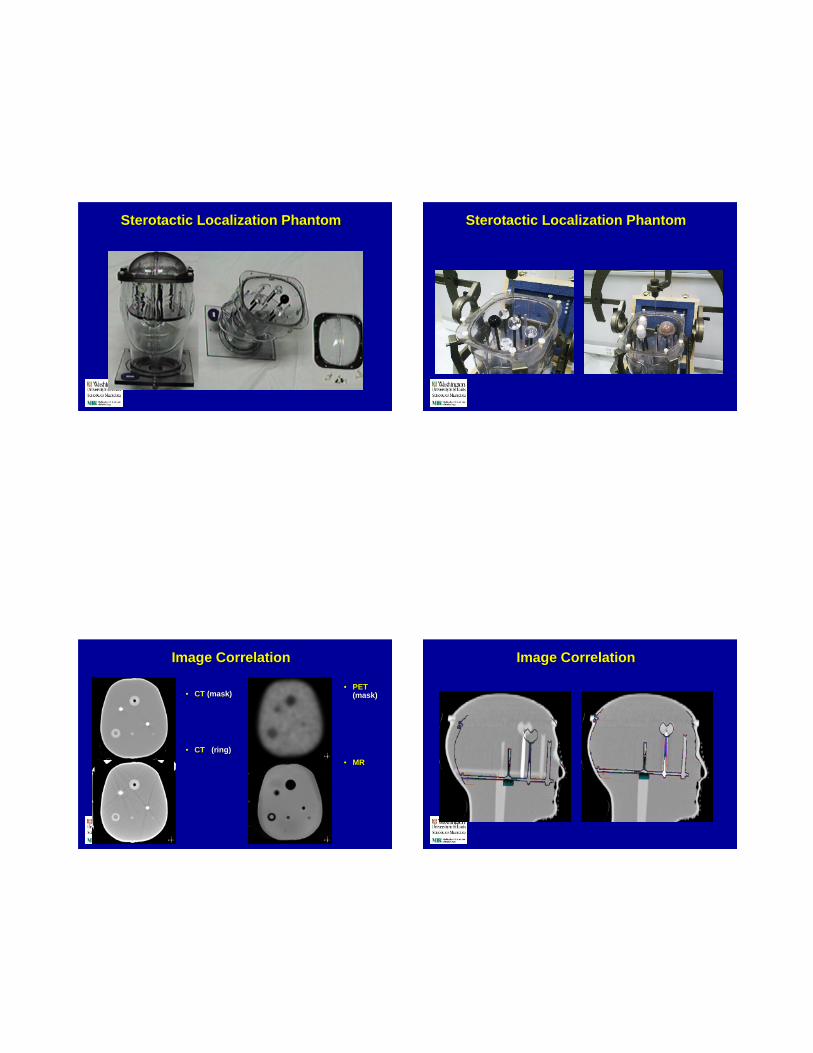
Sterotactic Loca lization PhantomSterotactic Loca lization Phantom Sterotactic Loc alizatio n PhantomSterotactic Loca lizatio n Phantom
Image Corr elationImage Corr elation
•• CTCT (mask)(mask)
•• CTCT (ring )(rin g)
•• PETPET(mask)(mask)
•• MRMR
Image Correl ationImage Correl ation

Image Corr elationImage Corr elation
CT with CT CT with MR CT wit hCT with CT CT with MR CT with PETPET
Image Correl ationImage Correl ation
CT with CT CT with MR CT withCT wit h CT CT with MR CT with PETPET
Contour Corre lationContour Corre lation
MR PETMR PET (mask )(mask)
ConclusionConclusion•• Accurate target iden tification remains one of the great estAcc urat e target identificatio n remains one of the greatest
avenues for improvem ent in the radiation therapyavenues for improve ment in the radiation therapytreatment planningtrea tment planning
•• Multi modal ity imagin g is a valuable tool in this processMultimodality imaging is a valuable tool in th is pro cessand its use in radiation oncology is constant ly increasingand its use in radiation oncolo gy is con stantly incr easing
•• CT wi ll remai n the primary imaging modality in RTCT wil l remain the primary imaging modality in RT•• Implementation of mult imodality scan ner in radiatio nImpl ementa tion of multimodality scanner in radiat ion
therapy setting increases demands on therapy physicistthera py setti ng increases demands on therap y physicist ’’ssexpertis e in imaging QAexpertise in imaging QA
•• Help from diagnostic phys icis ts is very impo rtan t in th isHelp from diagnostic physicists is very imp ortant in thisprocesspro cess