page ar15 & ,308 instructions - ar15 upper receivers ... 4 ar15 & ,308 instructions after...
TRANSCRIPT

Page �1 AR15 & ,308 instructions
Introduction."This is the jig instructions for the vytamenc tactical ar15 and 308 jigs. although both jigs are sold separate the instructions are the same. The top plates from the two jigs are modular so feel free to interchange the top plates if you own both jigs. both sets of side plates have a lifetime warranty so if you wear out the side plates send them back we will replace them. we have been manufacturing these jigs since 2009 so all top plates no mater when you purchased them will work on all of our jigs. This project could take up to 6 hours measure 5 times to cut once.""DISCLAIMER"ENCLOSED JIG AND INSTRUCTIONS ARE INTENDED FOR THE USE ON 80% RECEIVERS. IT HAS BEEN TESTED ON MOST POPULAR FORGED AND BILLET 80% RECEIVERS CURRENTLY ON THE MARKET. THE JIG IS INTENDED FOR USE TO FINISH 80% RECEIVERS ONLY AND IN NO WAY DESIGNED TO FINISH RECEIVERS ANY LESS THAN THE INDUSTRY STANDARD FOR A 80% RECEIVER, IT IS THE USEERS RESPONSIBILITY TO DETERMINE IF FINISHING AN 80% RECEIVER IS PERMITTED BY LAW IN THEIR STATE AND OR MUNICIPALITY. THIS INSTRUCTION SHEET IS OFFERED FOR EDUCATIONAL PURPOSES ONLY. THE AUTHOR ASSUMES NO LIABILITY WHAT SO EVER FOR ANY LEGAL OBLIGATIONS OR MISUSE OF THIS INFORMATION. THESE INSTRUCTIONS ARE INTENDED FOR THE USE BY SOMEONE WHOM HAS KNOWLEDGE OF MACHINERY AND MACHINE TOOLING NECESSARY TO COMPLETE AN 80% RECEIVER. THE AUTHOR ASSUMES NO LIABILITY FOR MISUSE OR DAMAGE: BODILY; MACHINERY, RECEIVER OR OTHERWISE. PURCHASE OF THIS JIG AND ITS INSTRUCTIONS IS ACCEPTED ON THESE TERMS. PLEASE BE SAFE IN COMPLETING YOUR PROJECT. ALWAYS USE EYE PROTECTION AND KEEP FIRST AID SUPPLIES NEAR BY. REMEMBER TAKE YOUR TIME. TAKE YOUR TIME TAKE YOUR TIME. ""TOOLS NEEDED"1. 5/32 DRILL BIT (USED FOR HAMMER AND TRIGGER HOLES)"2. 3/8 DRILL BIT ( USED TO DRILL SEFTY SELECTOR HOLE )"3. 5/8 DRILL BIT "4. 3/8 END MILL (2 FLUTE OR 3 FLUTE ONLY) 3/8 MILL BIT 3/8 SHANK 1 3/8- 1 1/2 FLUTE
LENGTH 4 INCHES OVERALL LENGTH"5. 5/16 2 FLUTE END MILL 3/8 SHANK 1” FLUTE LENGTH 4” OVER ALL LENGTH"6. 1/2 END MILL OPTIONAL 1/2 END MILL 3/8 SHANK 1.5” FLUTH LENGTH 4 INCHES
OVERALL LENGTH"7. DIGITAL DEPTH GUAGE"8. DIGITAL CALIPERS"9. MILL OR DRILL PRESS"10. VYTAMENC TACTICAL JIG AR15 OR .308"11. 80% LOWER"12. SAFTY GLASSES" """"STEP 1 "Open your Vytamenc tactical jig. it will come with 3 top plates 2 side plates 4 1/4x20 socket head cap screws (3/4 inch long) used for securing top plates. 2 1/4x20 ( 2” long) these screws are used for securing the side plates together. you will either have a single or double drill
PAGE 2 AR15 & ,308 instructions
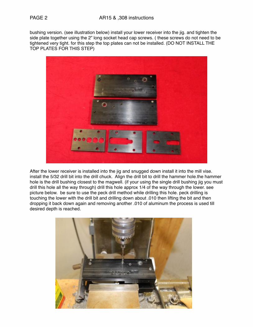
bushing version. (see illustration below) install your lower receiver into the jig. and tighten the side plate together using the 2” long socket head cap screws. ( these screws do not need to be tightened very tight. for this step the top plates can not be installed. (DO NOT INSTALL THE TOP PLATES FOR THIS STEP)"
After the lower receiver is installed into the jig and snugged down install it into the mill vise. install the 5/32 drill bit into the drill chuck. Align the drill bit to drill the hammer hole.the hammer hole is the drill bushing closest to the magwell. (if your using the single drill bushing jig you must drill this hole all the way through) drill this hole approx 1/4 of the way through the lower. see picture below. be sure to use the peck drill method while drilling this hole. peck drilling is touching the lower with the drill bit and drilling down about .010 then lifting the bit and then dropping it back down again and removing another .010 of aluminum the process is used till desired depth is reached.

PAGE 3 AR15 & ,308 instructions
"after this hole has reached desired depth flip the jig over and drill the hammer hole on the back side of the jig to the same depth 1/4 of the way through the lower receiver. see picture "
STEP 2""keeping the same drill bit in the chuck(5/32) you are now ready to drill the trigger hole using the same concept drill the trigger hole( on single sided drill bushing jigs this hole must be drilled all the way through) use the peck drill method drill 1/4 of the way through on the same side the fixture is currently on see picture below
PAGE 4 AR15 & ,308 instructions
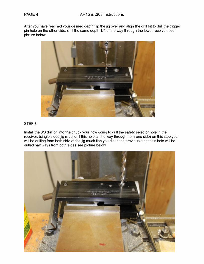
After you have reached your desired depth flip the jig over and align the drill bit to drill the trigger pin hole on the other side. drill the same depth 1/4 of the way through the lower receiver. see picture below."
STEP 3""Install the 3/8 drill bit into the chuck your now going to drill the safety selector hole in the receiver. (single sided jig must drill this hole all the way through from one side) on this step you will be drilling from both side of the jig much lion you did in the previous steps this hole will be drilled half ways from both sides see picture below

PAGE 5 AR15 & ,308 instructions
After reaching the desired depth flip the jig over and drill half ways through from the other side you will see daylight through this hole when finished. see picture below."
The reason why you are not drill all the way through with the double drill bushing jig is because you will be removing the center portion with the milling bit in future steps. remember keep everything lubed up with a cutting fluid while drilling. remove jig from vice" "STEP 4"while holding the jig in your hand loosen the side plates (1/4x20 socket head cap screws) and install top plate #1 onto the jig you can not do this when these screws are tight.

PAGE 6 AR15 & ,308 instructions
when installing this plate it will only go on one way. there is writing machined into the bottom this side goes down. there is also a radius on one side of this plate that side go towards the buffer tube. secure this plate and remember it does not have to be to tight just snug. snug side plate screws. Install the jig into the vise. install the 5/8 drill bit into the chuck. drill all of the 5/8 holes to a rough depth of 1.20” see pictures below. use peck drill method"
Drill second 5/8 hole to depth 1.20” use peck drill method"
""""""
PAGE 7 AR15 & ,308 instructions
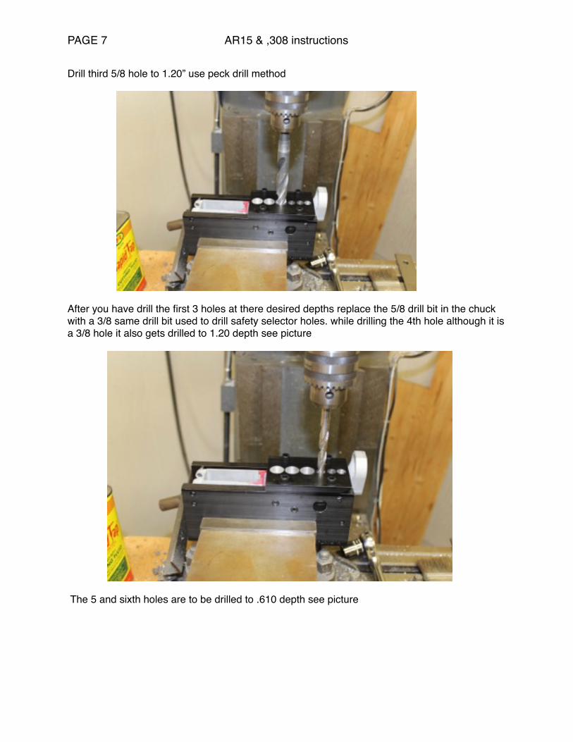
Drill third 5/8 hole to 1.20” use peck drill method"
After you have drill the first 3 holes at there desired depths replace the 5/8 drill bit in the chuck with a 3/8 same drill bit used to drill safety selector holes. while drilling the 4th hole although it is a 3/8 hole it also gets drilled to 1.20 depth see picture"
The 5 and sixth holes are to be drilled to .610 depth see picture""""""

PAGE 8 AR15 & ,308 instructions
The 6th hole also must be drilled to .610"
"

PAGE 9 AR15 & ,308 instructions
STEP 5"Remove the jig from the vise loosen up the side plates remove the top plate and install the top plate labeled #2. this plate can only be installed one way. with the writing on the bottom plate down and the radius towards the buffer tube. you top plate will look like the picture below "
after the installation of this top plate is complete top plate socket head cap screws are snug tighten the side plate socket head cap screws remember do not over tighten these screws they only have to be snug. install jig into your milling vise. at this point you can use the optional 1/2 end mill to machine out the center portion of this plate. do not use the 1/2 end mill to cut the final pass it does not give you a tight enough radius. the final cut must be done with a 3/8 end mill. machine down to 1.250 NOTE ALL MEASUREMENTS MUST BE TAKE FROM THE TOP OF THE PART NOT THE JIG OR THE TOP PLATE. On your final pass remember to just skim the top plate to get as close to the spec as possible. remember your going to touch the top plates. if you want to remove the top plates see what your doing better you can. be sure to make your final pass with the top plate on. you must be at least 1.250 or your trigger will not drop. see picture below.

PAGE 10 AR15 & ,308 instructions
STEP 6"Remove the jig from the milling vise loosen the side plate screws remove the top plate and install the top plate labeled #3 this plate can only be installed one way. The writing will be down and the radius will face the buffer tube. This plate will allow you to finish the rear fire control pocket and the trigger slot. see picture below."
After this plate is installed keep the same 3/8 end mill in the machine. The rear fire control pocket is the portion of this top plate that is closest to the duffer tube mount. machine this area to a finish depth of .630 this area must be finished with a 3/8 mill bit to assure the correct radius in the corners. NOTE DO NOT RUN INTO THE BUFFER TUBE ASSEMBLY WITH THE MILL WHILE MACHINING THE AREA BY THE BUFFER TUBE DETENT. BE SURE THAT THE END MILL IS HANGING DOWN FAR ENOUGH IN THE COLLET TO CLEAR THIS AREA. also be careful not to run the end mill into the buffer tube detent area. see picture below

PAGE 11 AR15 & ,308 instructions
STEP 7"After the desired depth is reached in rear fire control area switch end mill bits to a 5/16 align the mill to set up for the trigger hole. you do not have to change top plates or even remove the jig from the vice. drop the end mill through the slot in plate #3 and punch a hole in the floor of the lower receiver machine it back and forth till you have removed all of the material through the hole that is possible. there is no depth that you have to hit on this one. but keep in mind the fort her you go through you may hit the intergraded trigger guard on a billet lower. see pic below

PAGE 12 AR15 & ,308 instructions
"after putting the hole in the bottom of the lower for the trigger to drop into. you can now remove the lower from your jig and install a lower parts kit in the fire control area to preform a function test. you lower is complete and should look like the picture below.

PAGE 13 AR15 & ,308 instructions
"any technical questions please feel free to call our shop at 562-691-5790. ""replacement parts are list on our web site at vytamenctactical.com "TOP PLATE PART NUMBERS"PLATE 1. AR15FCPDP (DRILL PLATE)"PLATE 2. AR15FCPTP (FIRE CONTOL POCKET MILL PLATE FRONT)"PLATE 3. RMP ( REAR FIRE CONTROL POCKET AND TRIGGER PLATE)""