owner's please read this inverter manual pure sine wave...
TRANSCRIPT

DC-AC Power Inverter Pure Sine Wave
PST-1500-12PST-1500-24PST-2000-12PST-2000-24
Please read this manual before installing your inverter
owner's Manual

2 | SAMLEX AMERICA INC.
Owner's MAnuAl | Index
Section 1 Safety Instructions ........................................3
Section 2 General Information .....................................6
Section 3 Limiting Electromagnetic Interference (EMI) ....................... 11
Section 4Powering Direct / Embedded Switch Mode Power Supplies (SMPS) ....................................................... 12
Section 5 Principle of Operation ............................... 14
Section 6 Layout ........................................................ 15
Section 7General Information on Batteries for Powering Inverters ........................................................ 16
Section 8 Installation ................................................. 27
Section 9 Operation ...................................................36
Section 10 Protections ............................................. 38
Section 11 Trouble Shooting Guide ......................... 40
Section 12 Specifications ......................................... 42
Section 13 Warranty ..................................................46
DetAiLeD PRoDUct inFoRMAtion
For a complete user manual including specifications, application notes, installation instructions, trouble shooting and more, please visit the web page for this product on www. samlexamerica.com. Product page can be found using the “Search by Model” field.

2 | SAMLEX AMERICA INC. SAMLEX AMERICA INC. | 3
seCtIOn 1 | safety Instructions
The following safety symbols will be used in this manual to highlight safety and information:
WARninG!
Indicates possibility of physical harm to the user in case of non-compliance.
! cAUtion!
Indicates possibility of damage to the equipment in case of non-compliance.
i
inFo
Indicates useful supplemental information.
Please read these instructions before installing or operating the unit to prevent personal injury or damage to the unit.
SAFetY inStRUctionS - GeneRAL
installation and wiring compliance
• InstallationandwiringmustcomplywiththeLocalandNationalElectricalCodesandmust be done by a certified electrician.
Preventing electrical shock
• Alwaysconnectthegroundingconnectionontheunittotheappropriategroundingsystem.
• Disassembly/repairshouldbecarriedoutbyqualifiedpersonnelonly.
• DisconnectallACandDCsideconnectionsbeforeworkingonanycircuitsassociatedwith the unit. Turning the oN/off switch on the unit to off position may not entirely remove dangerous voltages.
• Becarefulwhentouchingbareterminalsofcapacitors.Thecapacitorsmayretainhighlethalvoltagesevenafterthepowerhasbeenremoved.Dischargethecapacitorsbeforeworkingonthecircuits.
installation environment
• Theinvertershouldbeinstalledindooronlyinawellventilated,cool,dry environment
• Donotexposetomoisture,rain,snoworliquidsofanytype.
• Toreducetheriskofoverheatingandfire,donotobstructthesuctionanddischargeopenings of the cooling fans.
• Toensureproperventilation,donotinstallinalowclearancecompartment.

4 | SAMLEX AMERICA INC.
seCtIOn 1 | safety Instructions
Preventing fire and explosion hazards
• Workingwiththeunitmayproducearcsorsparks.Thus,theunitshouldnotbeusedin areas where there are flammable materials or gases requiring ignition protected equipment.Theseareasmayincludespacescontaininggasoline-poweredmachinery,fueltanks,andbatterycompartments.
Precautions when working with batteries
• Batteriescontainverycorrosivedilutedsulphuricacidaselectrolyte.Precautionsshouldbetakentopreventcontactwithskin,eyesorclothing.
• BatteriesgenerateHydrogenandoxygenduringchargingresultinginevolutionofexplosivegasmixture.Careshouldbetakentoventilatethebatteryareaandfollowthe battery manufacturer’s recommendations.
• Neversmokeorallowasparkorflamenearthebatteries.
• Usecautiontoreducetheriskofdroppingametaltoolonthebattery.Itcouldsparkorshortcircuitthebatteryorotherelectricalpartsandcouldcauseanexplosion.
• Removemetalitemslikerings,braceletsandwatcheswhenworkingwithbatteries.The batteries can produce a short circuit current high enough to weld a ring or the liketometalandthuscauseasevereburn.
• Ifyouneedtoremoveabattery,alwaysremovethegroundterminalfromthebatteryfirst.Makesurethatalltheaccessoriesareoffsothatyoudonotcauseaspark.
SAFetY inStRUctionS - inVeRteR ReLAteD
Preventing Paralleling of the Ac output TheACoutputoftheunitshouldneverbeconnecteddirectlytoanElectricalBreakerPanel/LoadCentrewhichisalsofedfromtheutilitypower/generator.SuchadirectconnectionmayresultinparalleloperationofthedifferentpowersourcesandACpowerfromtheutility/generatorwillbefedbackintotheunitwhichwillinstantlydamage the output section of the unit and may also pose a fire and safety hazard. If an ElectricalBreakerPanel/LoadCenterisfedfromthisunitandthispanelisalsorequiredtobefedfromadditionalalternateACsources,theACpowerfromalltheACsources(liketheutility/generator/thisinverter)shouldfirstbefedtoanAutomatic/ManualSelector Switch and the output of the Selector Switch should be connected to the elec-tricalBreakerPanel/LoadCenter.
! cAUtion!Topreventpossibilityofparallelingandseveredamagetotheunit,neveruseasimplejumpercablewithamaleplugonbothendstoconnecttheACoutputoftheunittoahandywallreceptacleinthehome/RV.
Preventing Dc input over Voltage ItistobeensuredthattheDCinputvoltageofthisunitdoesnotexceed16.5VDCfor
4 | SAMLEX AMERICA INC. SAMLEX AMERICA INC. | 5
seCtIOn 1 | safety Instructions
the12Vbatteryversionand33.0VDCforthe24Vbatteryversiontopreventpermanentdamage to the unit. Please observe the following precautions:
• Ensurethatthemaximumchargingvoltageoftheexternalbatterycharger/alterna-tor/solarchargecontrollerdoesnotexceed16.5VDCforthe12Vbatteryversionand33.0VDCforthe24Vbatteryversion
• Donotuseunregulatedsolarpanelstochargethebatteryconnectedtothisunit.Undercoldambienttemperatures,theoutputofthesolarpanelmayreach>22VDCfor12VBatterySystemand>44VDCforthe24VBatterysystem.Alwaysuseachargecontroller between the solar panel and the battery.
• Donotconnectthisunittoabatterysystemwithavoltagehigherthantheratedbat-teryinputvoltageoftheunit(e.g.donotconnectthe12Vversionoftheunitto24Vbatterysystemorthe24Vversiontothe48VBatterySystem)
Preventing Reverse Polarity on the input Side Whenmakingbatteryconnectionsontheinputside,makesurethatthepolarityofbat-teryconnectionsiscorrect(ConnectthePositiveofthebatterytothePositiveterminaloftheunitandtheNegativeofthebatterytotheNegativeterminaloftheunit).Iftheinputisconnectedinreversepolarity,DCfuse(s)insidetheinverterwillblowandmayalso cause permanent damage to the inverter.
! cAUtion!Damagecausedbyreversepolarityisnotcoveredbywarranty.
Using Hard Wiring Ac output connections in Vehicles
WARninG!
RiSK oF eLectRic SHocK When this unit is installed in vehicles and hard-wiring connection is used to feedtheACoutputoftheinvertertotheACDistributionPanel/LoadCenterinthevehicle,itistobeensuredthatGroundfaultCircuitInterrupter(s)[GfCI]areinstalled in the vehicle wiring system to protect all branch circuits.
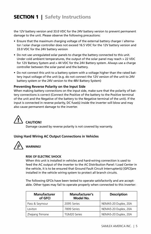
ThefollowingGfCIshavebeentestedtooperatesatisfactorilyandareaccept-able. other types may fail to operate properly when connected to this inverter:
Manufacturer of GFci
Manufacturer's Model no.
Description
Pass & Seymour 2095 Series NEMA5-20 Duplex, 20A
Leviton 7899 Series NEMA5-20 Duplex, 20A
Zhejiang Trimone TGM20 Series NEMA5-20 Duplex, 20A

6 | SAMLEX AMERICA INC.
seCtIOn 2 | General Information
Thefollowingdefinitionsareusedinthismanualforexplainingvariouselectrical concepts,specificationsandoperations:
Peak Value:Itisthemaximumvalueofelectricalparameterlikevoltage/current.
RMS (Root Mean Square) Value: It is a statistical average value of a quantity that varies invaluewithrespecttotime.forexample,apuresinewavethatalternatesbetweenpeakvaluesofPositive169.68VandNegative169.68VhasanRMSvalueof120VAC.Also,forapuresinewave,theRMSvalue=Peakvalue÷1.414.
Voltage (V), Volts:Itisdenotedby“V”andtheunitis“Volts”.Itistheelectricalforcethatdriveselectricalcurrent(I)whenconnectedtoaload.ItcanbeDC(DirectCurrent–flowinonedirectiononly)orAC(AlternatingCurrent–directionofflowchangesperi-odically).TheACvalueshowninthespecificationsistheRMS(RootMeanSquare)value.
current (i), Amps, A:Itisdenotedby“I”andtheunitisAmperes–shownas“A”.Itistheflowofelectronsthroughaconductorwhenavoltage(V)isappliedacrossit.
Frequency (F), Hz: It is a measure of the number of occurrences of a repeating event per unittime.forexample,cyclespersecond(orHertz)inasinusoidalvoltage.
efficiency, (η):ThisistheratioofPoweroutput÷PowerInput.
Phase Angle, (φ): It is denoted by “φ”andspecifiestheangleindegreesbywhichthecurrent vector leads or lags the voltage vector in a sinusoidal voltage. In a purely induc-tiveload,thecurrentvectorlagsthevoltagevectorbyPhaseAngle(φ)=90°.Inapurelycapacitiveload,thecurrentvectorleadsthevoltagevectorbyPhaseAngle,(φ)=90°.Inapurelyresistiveload,thecurrentvectorisinphasewiththevoltagevectorandhence,thePhaseAngle,(φ)=0°.Inaloadconsistingofacombinationofresistances,induct-ancesandcapacitances,thePhaseAngle(φ)ofthenetcurrentvectorwillbe>0°<90°and may lag or lead the voltage vector. Resistance (R), Ω: It is the property of a conductor that opposes the flow of current whenavoltageisappliedacrossit.Inaresistance,thecurrentisinphasewiththevolt-age. It is denoted by "r" and its unit is "ohm" - also denoted as "Ω".
inductive Reactance (XL), capacitive Reactance (Xc) and Reactance (X): reactance is the opposition of a circuit element to a change of electric current or voltage due to that element's inductance or capacitance. Inductive reactance (XL)isthepropertyofacoilof wire in resisting any change of electric current through the coil. It is proportional to frequency and inductance and causes the current vector to lag the voltage vector by PhaseAngle(φ)=90°.Capacitivereactance(Xc)isthepropertyofcapacitiveelementstooppose changes in voltage. Xc is inversely proportional to the frequency and capacitance andcausesthecurrentvectortoleadthevoltagevectorbyPhaseAngle(φ)=90°.Theunit of both XL and Xc is "ohm" - also denoted as "Ω". The effects of inductive reac-tance XLtocausethecurrenttolagthevoltageby90°andthatofthecapacitivereac-tance Xctocausethecurrenttoleadthevoltageby90°areexactlyoppositeandthenet

6 | SAMLEX AMERICA INC. SAMLEX AMERICA INC. | 7
effectisatendencytocanceleachother.Hence,inacircuitcontainingbothinductancesandcapacitances,thenetReactance (X) will be equal to the difference between the values of the inductive and capacitive reactances. The net Reactance (X) will be inductive if XL>Xc and capacitive if Xc>XL.
impedance, Z: It is the vectorial sum of resistance and reactance vectors in a circuit. ActivePower(P),Watts:Itisdenotedas“P”andtheunitis“Watt”.Itisthepowerthatisconsumedintheresistiveelementsoftheload.AloadwillrequireadditionalReactivePower for powering the inductive and capacitive elements. The effective power required wouldbetheApparentPowerthatisavectorialsumoftheActiveandReactivePowers.
Reactive Power (Q), VAR: Is denoted as “Q”andtheunitisVAR.overacycle,thispoweris alternatively stored and returned by the inductive and capacitive elements of the load. It is not consumed by the inductive and capacitive elements in the load but a certain valuetravelsfromtheACsourcetotheseelementsinthe(+)halfcycleofthesinusoidalvoltage(Positivevalue)andthesamevalueisreturnedbacktotheACsourceinthe(-)halfcycleofthesinusoidalvoltage(Negativevalue).Hence,whenaveragedoveraspanofonecycle,thenetvalueofthispoweris0.However,onaninstantaneousbasis,thispowerhastobeprovidedbytheACsource.Hence, the inverter, AC wiring and over cur-rent protection devices have to be sized based on the combined effect of the Active and Reactive Powers that is called the Apparent Power.
Apparent (S) Power, VA:Thispower,denotedby"S",isthevectorialsumoftheActivePowerinWattsandtheReactivePowerin“VAR”.Inmagnitude,itisequaltotheRMSvalueofvoltage“V”XtheRMSvalueofcurrent“A”.TheUnitisVA.Please note that Apparent Power VA is more than the Active Power in Watts. Hence, the inverter, AC wir-ing and over current protection devices have to be sized based on the Apparent Power.
Power Factor, (PF):Itisdenotedby“Pf”andisequaltotheratiooftheActivePower(P)inWattstotheApparentPower(S)inVA.Themaximumvalueis1forresistivetypesofloadswheretheActivePower(P)inWatts=theApparentPower(S)inVA.Itis0forpurelyinductiveorpurelycapacitiveloads.Practically,theloadswillbeacombinationofresistive,inductiveandcapacitiveelementsandhence,itsvaluewillbe>0<1.Normallyitrangesfrom0.5to0.8.
Load: electrical appliance or device to which an electrical voltage is fed.
Linear Load: Aloadthatdrawssinusoidalcurrentwhenasinusoidalvoltageisfedtoit.Examplesare,incandescentlamp,heater,electricmotor,etc.
non-Linear Load:Aloadthatdoesnotdrawasinusoidalcurrentwhenasinusoidalvolt-ageisfedtoit.forexamplenon-powerfactorcorrectedSwitchedModePowerSupplies(SMPS)usedincomputers,audiovideoequipment,batterychargers,etc.
Resistive Load:Adeviceorappliancethatconsistsofpureresistance(likefilamentlamps,cooktops,toaster,coffeemakeretc.)anddrawsonlyActivePower(Watts)from
seCtIOn 2 | General Information

8 | SAMLEX AMERICA INC.
theinverter.TheinvertercanbesizedbasedontheActivePowerrating(Watts)withoutcreating overload. Reactive Load:Adeviceorappliancethatconsistsofacombinationofresistive,induc-tiveandcapacitiveelements(likemotordriventools,refrigerationcompressors,micro-waves,computers,audio/videoetc.).ThesedevicesrequireApparentPower(VA)fromtheinvertertooperate.TheApparentPowerisavectorialsumofActivePower(Watts) andReactivePower(VAR).The inverter has to be sized based on the higher Apparent Power (VA).
output Voltage Waveforms
Fig. 2.1: Pure and Modified Sine Waveforms
TheoutputwaveformoftheSamlexPSTseriesinvertersisapuresinewavelikethewaveform of the grid power. Please see sine wave represented in the fig. 2.1 that also shows modified waveform for comparison.
Inasinewave,thevoltagerisesandfallssmoothlywithasmoothlychangingphaseangleandalsochangesitspolarityinstantlywhenitcrosses0Volts.Inamodifiedsinewave,thevoltagerisesandfallsabruptly,thephaseanglealsochangesabruptlyanditsitsat0Vsforsometimebeforechangingitspolarity.Thus,anydevicethatusesacontrolcircuitrythatsensesthephase(forvoltage/speedcontrol)orinstantaneouszerovoltagecrossing(fortimingcontrol)willnotworkproperlyfromavoltagethathasamodified sine waveform.
Also,asthemodifiedsinewaveisaformofsquarewave,itiscomprisedofmultiplesinewavesofoddharmonics(multiples)ofthefundamentalfrequencyofthemodifiedsinewave.forexample,a60Hzmodifiedsinewavewillconsistofsinewaveswithoddharmonicfrequenciesof3rd(180Hz),5th(300Hz),7th(420Hz)andsoon.Thehigh
seCtIOn 2 | General Information
TIME
180160140120100
80604020
020406080
100120140160180
Modi�ed Sine Wave sits at ZERO for some time and then rises or falls
Modi�ed Sine Wave
Sine Wave
Pure Sine Wavecrosses 0.0V instantaneously

8 | SAMLEX AMERICA INC. SAMLEX AMERICA INC. | 9
seCtIOn 2 | General Information
frequency harmonic content in a modified sine wave produces enhanced radio interfer-ence,higherheatingeffectininductiveloadslikemicrowavesandmotordrivendeviceslikehandtools,refrigeration/air-conditioningcompressors,pumpsetc.Thehigherfrequency harmonics also produce overloading effect in low frequency capacitors due to lowering of their capacitive reactance by the higher harmonic frequencies. These capaci-tors are used in ballasts for fluorescent lighting for Power factor improvement and in single-phaseinductionmotorsasstartandruncapacitors.Thus,modifiedandsquarewave inverters may shut down due to overload when powering these devices.
Advantages of Pure Sine Wave inverters
• Theoutputwaveformisasinewavewithverylowharmonicdistortionandcleanerpowerlikeutilitysuppliedelectricity.
• Inductiveloadslikemicrowaves,motors,transformersetc.runfaster,quieter and cooler.
• Moresuitableforpoweringfluorescentlightingfixturescontainingpowerfactorimprovement capacitors and single phase motors containing start and run capacitors
• Reducesaudibleandelectricalnoiseinfans,fluorescentlights,audioamplifiers,TV,faxandansweringmachines.
• Doesnotcontributetothepossibilityofcrashesincomputers,weirdprintoutsandglitches in monitors.
Some examples of devices that may not work properly with modified sine wave and may also get damaged are given below:
• Laserprinters,photocopiers,andmagneto-opticalharddrives.
• Built-inclocksindevicessuchasclockradios,alarmclocks,coffeemakers,bread-mak-ers,VCR,microwaveovensetc.maynotkeeptimecorrectly.
• outputvoltagecontroldeviceslikedimmers,ceilingfan/motorspeedcontrolmaynotworkproperly(dimming/speedcontrolmaynotfunction).
• Sewingmachineswithspeed/microprocessorcontrol.
• Transformer-lesscapacitiveinputpowereddeviceslike(i)Razors,flashlights,night-lights,smokedetectorsetc.(ii)Re-chargersforbatterypacksusedinhandpowertools. These may get damaged. Please check with the manufacturer of these types of devices for suitability.
• DevicesthatuseradiofrequencysignalscarriedbytheACdistributionwiring.
• Somenewfurnaceswithmicroprocessorcontrol/oilburnerprimarycontrols.
• Highintensitydischarge(HID)lampslikeMetalHalidelamps.These may get damaged. Please check with the manufacturer of these types of devices for suitability.
• Somefluorescentlamps/lightfixturesthathavepowerfactorcorrectioncapacitors.The inverter may shut down indicating overload.

10 | SAMLEX AMERICA INC.
Power Rating of the invertersThecontinuousoutputpowerratingoftheinverterisspecifiedinActivePowerinWattsforresistivetypesofloadslikeheatingelements,incandescentlampsetc.wherePowerfactor(Pf)=1.TheSurgePowerratingisfor<1sec.
Nonresistive/reactiveloadswithPowerfactor<1likemotors(Pf=0.4to0.8),nonPowerfactorcorrectedelectronics(Pf=0.5to0.6)etc,willdrawhigherApparentPowerinVoltAmps(VA).ThisApparentPoweristhesumofActivePowerinWattsplusReac-tivePowerinVARandis=ActivePowerinWatts÷Powerfactor.Thus,forsuchreactiveloads,highersizedinverterisrequiredbasedontheApparentPower.further,allreac-tivetypesofloadsrequirehigherinrush/startingsurgepowerthatmaylastfor >1to5secandsubsequentlowerrunningpower.IftheinverterisnotsizedadequatelybasedonthetypeofACload,itislikelytoshutdownorfailprematurelydueto repeated overloading.
i
inFo
The manufacturers’ specification for power rating of the appliances and devices indicates only the running power required. The surge power required by some specifictypesofdevicesasexplainedabovehastobedeterminedbyactualtest-ingorbycheckingwiththemanufacturer.Thismaynotbepossibleinallcasesandhence,canbeguessedatbest,basedonsomegeneralrulesofthumb.
Table2.1belowlistssomecommonloadsthatrequirehighsurgepoweronstartup.A“Sizingfactor”hasbeenrecommendedagainsteachwhichisamultiplicationfactortobeappliedtotheratedrunningWattratingoftheloadtoarriveattheContinuousPowerRatingoftheinverter(MultiplytherunningWattsofthedevice/appliancebytheSizingfactortoarriveatthesizeoftheinverter).
tABLe 2.1: inVeRteR SiZinG FActoRtype of Device or Appliance
inverter Sizing Factor*
AirConditioner/Refrigerator/freezer(Compressorbased) 5
AirCompressor 4
SumpPump/WellPump/SubmersiblePump 3
Dishwasher/ClothesWasher 3
Microwave(whereratedoutputpoweristhecookingpower) 2
furnace fan 3
Industrial Motor 3
PortableKerosene/DieselfuelHeater 3
CircularSaw/BenchGrinder 3
Incandescent/Halogen/QuartzLamps 3
TableContinuesNextPage►
seCtIOn 2 | General Information
10 | SAMLEX AMERICA INC. SAMLEX AMERICA INC. | 11
tABLe 2.1: inVeRteR SiZinG FActoRtype of Device or Appliance
inverter Sizing Factor*
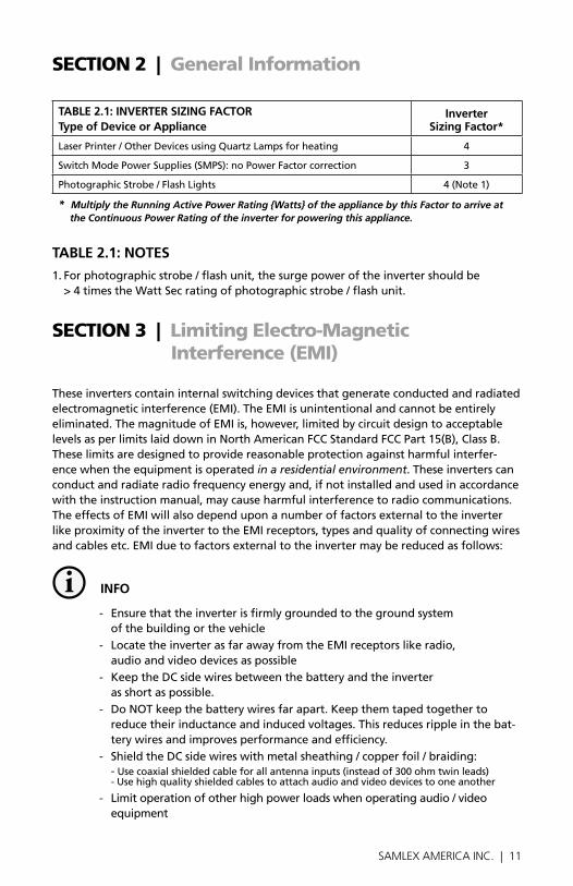
LaserPrinter/otherDevicesusingQuartzLampsforheating 4
SwitchModePowerSupplies(SMPS):noPowerfactorcorrection 3
PhotographicStrobe/flashLights 4(Note1)
* Multiply the Running Active Power Rating {Watts} of the appliance by this Factor to arrive at the Continuous Power Rating of the inverter for powering this appliance.
tABLe 2.1: noteS
1.forphotographicstrobe/flashunit,thesurgepoweroftheinvertershouldbe >4timestheWattSecratingofphotographicstrobe/flashunit.
seCtIOn 2 | General Information
seCtIOn 3 | limiting electro-Magnetic Interference (eMI)
These inverters contain internal switching devices that generate conducted and radiated electromagneticinterference(EMI).TheEMIisunintentionalandcannotbeentirelyeliminated.ThemagnitudeofEMIis,however,limitedbycircuitdesigntoacceptablelevelsasperlimitslaiddowninNorthAmericanfCCStandardfCCPart15(B),ClassB.These limits are designed to provide reasonable protection against harmful interfer-ence when the equipment is operated in a residential environment. These inverters can conductandradiateradiofrequencyenergyand,ifnotinstalledandusedinaccordancewiththeinstructionmanual,maycauseharmfulinterferencetoradiocommunications.TheeffectsofEMIwillalsodependuponanumberoffactorsexternaltotheinverterlikeproximityoftheinvertertotheEMIreceptors,typesandqualityofconnectingwiresandcablesetc.EMIduetofactorsexternaltotheinvertermaybereducedasfollows:
i inFo
- ensure that the inverter is firmly grounded to the ground system of the building or the vehicle
- LocatetheinverterasfarawayfromtheEMIreceptorslikeradio, audio and video devices as possible
- KeeptheDCsidewiresbetweenthebatteryandtheinverter as short as possible.
- DoNoTkeepthebatterywiresfarapart.Keepthemtapedtogethertoreduce their inductance and induced voltages. This reduces ripple in the bat-tery wires and improves performance and efficiency.
- ShieldtheDCsidewireswithmetalsheathing/copperfoil/braiding:- Usecoaxialshieldedcableforallantennainputs(insteadof300ohmtwinleads)-Usehighqualityshieldedcablestoattachaudioandvideodevicestooneanother
- Limitoperationofotherhighpowerloadswhenoperatingaudio/videoequipment

12 | SAMLEX AMERICA INC.
seCtIOn 4 | Powering Direct / embedded switch Mode Power supplies (sMPs)
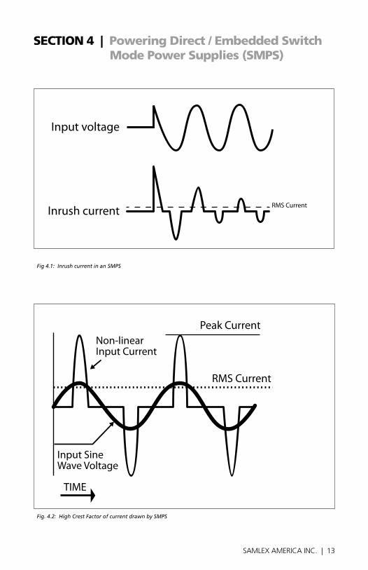
SwitchModePowerSupplies(SMPS)areextensivelyusedtoconverttheincomingACpowerintovariousvoltageslike3.3V,5V,12V,24Vetc.thatareusedtopowervariousdevicesandcircuitsusedinelectronicequipmentlikebatterychargers,computers,audioandvideodevices,radiosetc.Thesepowersuppliesuselargecapacitorsintheirinputsectionforfiltration.Whenthepowersupplyisfirstturnedon,thereisaverylargeinrush current drawn by the power supply as the input capacitors are charged (The ca-pacitorsactalmostlikeashortcircuitattheinstantthepoweristurnedon).Theinrushcurrent at turn-on is several to tens of times larger than the rated rMS input current andlastsforafewmilliseconds.Anexampleoftheinputvoltageversusinputcurrentwaveforms is given in fig. 4.1. It will be seen that the initial input current pulse just after turn-onis>15timeslargerthanthesteadystateRMScurrent.Theinrushdissipatesinaround2or3cyclesi.e.inaround33to50millisecondsfor60Hzsinewave.
further,duetothepresenceofhighvalueofinputfiltercapacitors,thecurrentdrawnbyanSMPS(WithnoPowerfactorcorrection)isnotsinusoidalbutnon-linearasshownin fig 4.2 above. The steady state input current of SMPS is a train of non-linear pulses instead of a sinusoidal wave. These pulses are two to four milliseconds duration each whenon50Hzpower,withaveryhighCrestfactorcorrespondingtopeakvaluesaround3timestheRMSvalueoftheinputcurrent: (Crestfactor=Peakvalue÷RMSvalue).
ManySMPSunitsincorporate“InrushCurrentLimiting”.ThemostcommonmethodistheNTC(NegativeTemperatureCoefficient)resistor.TheNTCresistorhasahighresist-ancewhencoldandalowresistancewhenhot.TheNTCresistorisplacedinserieswiththe input to the power supply. The cold resistance limits the input current as the input capacitorschargeup.TheinputcurrentheatsuptheNTCandtheresistancedrops duringnormaloperation.However,ifthepowersupplyisquicklyturnedoffandbackon,theNTCresistorwillbehotsoitslowresistancestatewillnotpreventaninrush current event.
Theinvertershould,therefore,besizedadequatelytowithstandthehighinrushcurrentandthehighCrestfactorofthecurrentdrawnbytheSMPS.Hence, it is recommended that for purposes of sizing the inverter, the continuous power of the inverter should be > 3 times the continuous rated power of the SMPS. For example, an SMPS rated at 100 Watts should be powered from an inverter that has continuous power of > 300 Watts.
12 | SAMLEX AMERICA INC. SAMLEX AMERICA INC. | 13
seCtIOn 4 | Powering Direct / embedded switch Mode Power supplies (sMPs)
Fig 4.1: Inrush current in an SMPS
Fig. 4.2: High Crest Factor of current drawn by SMPS
Input voltage
Inrush current RMS Current
TIME
Peak Current
RMS Current
Non-linearInput Current
Input SineWave Voltage

14 | SAMLEX AMERICA INC.
seCtIOn 5 | Principle of Operation
TheseinvertersconvertDCbatteryvoltagetoACvoltagewithanRMS(RootMeanSquare)valueof120VAC,60HzRMS.
ThewaveformoftheACvoltageisapuresinewaveformthatissameasthewaveformof grid power (Supplementary information on pure sine waveform and its advantages are discussed on pages 8 & 9).
fig.5.1belowspecifiesthecharacteristicsof120VAC,60Hzpuresinewaveform.Theinstantaneous value and polarity of the voltage varies cyclically with respect to time. for example,inonecycleina120VAC,60Hzsystem,itslowlyrisesinthepositivedirectionfrom0Vtoapeakpositivevalue“Vpeak”=+168.69V,slowlydropsto0V,changesthepolaritytonegativedirectionandslowlyincreasesinthenegativedirectiontoapeaknegativevalue“Vpeak”=-168.69Vandthenslowlydropsbackto0V.Thereare60such cyclesin1sec.Cyclespersecondiscalledthe“frequency”andisalsotermed“Hertz(Hz)”.
Fig. 5.1: 120 VAC, 60 Hz Pure Sine Waveform
Thevoltageconversiontakesplaceintwostages.Inthefirststage,theDCvoltageofthebatteryisconvertedtoahighvoltageDCusinghighfrequencyswitchingandPulseWidthModulation(PWM)technique.Inthesecondstage,thehighvoltageDCisconvertedto120VAC,60HzsinewaveACagainusingPWMtechnique.ThisisdonebyusingaspecialwaveshapingtechniquewherethehighvoltageDCisswitchedatahighfrequency and the pulse width of this switching is modulated with respect to a refer-ence sine wave.
TIMEOV
+
--VPEAK = - 168.69V
+VPEAK = + 168.69V VRMS = 120 VAC

14 | SAMLEX AMERICA INC. SAMLEX AMERICA INC. | 15
seCtIOn 6 | layout
Fig. 6.1: Layout of PST-1500 and PST-2000
L
N
12
16
15
1413
PST-1500 & PST-2000: FRONT
PST-1500 & PST-2000: FRONT - showing compartment containing AC output terminals for hardwiring.
PST-1500 & PST-2000: BACK
LEGEND
1. Power ON/OFF Switch
2. Green LED - Power ON
3. Red LED - Overload
4. Red LED - Over Temperature
5. NEMA5-20R GFCI Duplex Outlets
6. Cooling Fan Opening
7. Grounding Lug
8. Negative (-) DC Input Terminal
9. Positive (+) DC Input Terminal10. Modular Jack for RC-200 Remote Control
11. Metal Strain Relief Clamp for AC Output Cable
12. Cover Plate for Compartment Containing AC Output Terminals
13. Compartment Containing AC Output Terminals for Hardwiring
14. Terminal for AC Output Ground (Chassis Ground)
15. AC Output: Line Terminal
16. AC Output: Neutral Terminal
16 | SAMLEX AMERICA INC.
Lead-acidbatteriescanbecategorizedbythetypeofapplication:1. Automotiveservice-Starting/Lighting/Ignition(SLI,a.k.a.cranking),and2. Deepcycleservice.
DeepCycleLeadAcidBatteriesofappropriatecapacityarerecommendedforthe powering of inverters.
Deep cycle Lead Acid BatteriesDeepcyclebatteriesaredesignedwiththick-plateelectrodestoserveasprimarypowersources,tohaveaconstantdischargerate,tohavethecapabilitytobedeeplydis-chargedupto80%capacityandtorepeatedlyacceptrecharging.Theyaremarketedforuseinrecreationvehicles(RV),boatsandelectricgolfcarts–sotheymaybereferredtoasRVbatteries,marinebatteriesorgolfcartbatteries.UseDeepCyclebatteriesforpowering these inverters.
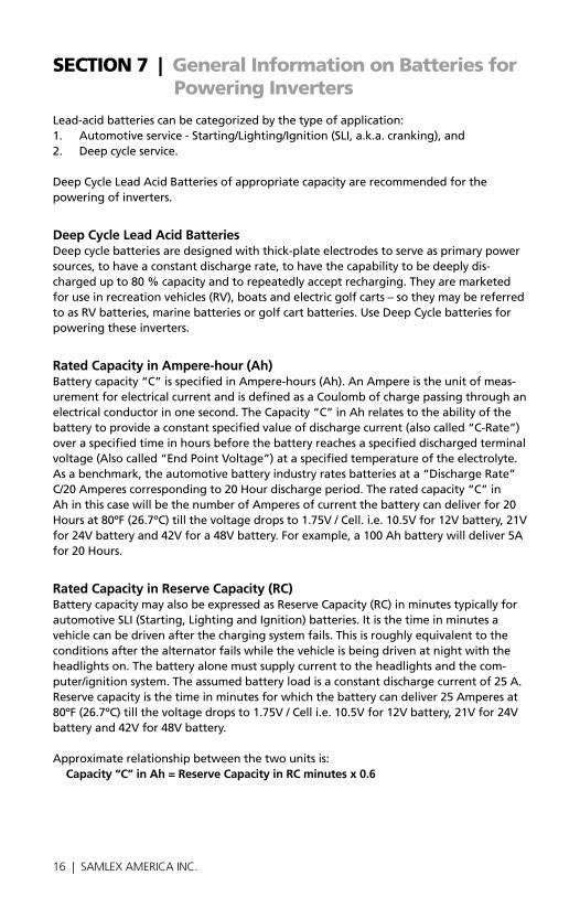
Rated capacity in Ampere-hour (Ah)Batterycapacity“C”isspecifiedinAmpere-hours(Ah).AnAmpereistheunitofmeas-urementforelectricalcurrentandisdefinedasaCoulombofchargepassingthroughanelectricalconductorinonesecond.TheCapacity“C”inAhrelatestotheabilityofthebatterytoprovideaconstantspecifiedvalueofdischargecurrent(alsocalled“C-Rate”)over a specified time in hours before the battery reaches a specified discharged terminal voltage(Alsocalled“EndPointVoltage”)ataspecifiedtemperatureoftheelectrolyte.Asabenchmark,theautomotivebatteryindustryratesbatteriesata“DischargeRate”C/20Amperescorrespondingto20Hourdischargeperiod.Theratedcapacity“C”inAhinthiscasewillbethenumberofAmperesofcurrentthebatterycandeliverfor20Hoursat80ºf(26.7ºC)tillthevoltagedropsto1.75V/Cell.i.e.10.5Vfor12Vbattery,21Vfor24Vbatteryand42Vfora48Vbattery.forexample,a100Ahbatterywilldeliver5Afor20Hours.
Rated capacity in Reserve capacity (Rc)BatterycapacitymayalsobeexpressedasReserveCapacity(RC)inminutestypicallyforautomotiveSLI(Starting,LightingandIgnition)batteries.Itisthetimeinminutesavehicle can be driven after the charging system fails. This is roughly equivalent to the conditions after the alternator fails while the vehicle is being driven at night with the headlights on. The battery alone must supply current to the headlights and the com-puter/ignitionsystem.Theassumedbatteryloadisaconstantdischargecurrentof25A.Reservecapacityisthetimeinminutesforwhichthebatterycandeliver25Amperesat80ºf(26.7ºC)tillthevoltagedropsto1.75V/Celli.e.10.5Vfor12Vbattery,21Vfor24Vbatteryand42Vfor48Vbattery.
Approximaterelationshipbetweenthetwounitsis:capacity “c” in Ah = Reserve capacity in Rc minutes x 0.6
seCtIOn 7 | General Information on Batteries for Powering Inverters

16 | SAMLEX AMERICA INC. SAMLEX AMERICA INC. | 17
seCtIOn 7 | General Information on Batteries for Powering Inverters
typical Battery Sizes
TheTable7.1belowshowsdetailsofsomepopularbatterysizes:
tABLe 7.1: PoPULAR BAtteRY SiZeS
Bci* Group Battery Voltage, V Battery capacity, Ah
27/31 12 105
4D 12 160
8D 12 225
GC2** 6 220
*BatteryCouncilInternational;**GolfCart
Specifying charging / Discharging currents: c-RateElectricalenergyisstoredinacell/batteryintheformofDCpower.Thevalueofthestored energy is related to the amount of the active materials pasted on the battery plates,thesurfaceareaoftheplatesandtheamountofelectrolytecoveringtheplates.Asexplainedabove,theamountofstoredelectricalenergyisalsocalledtheCapacityofthebatteryandisdesignatedbythesymbol“C”.
ThetimeinHoursoverwhichthebatteryisdischargedtothe“EndPointVoltage”forpurposesofspecifyingAhcapacitydependsuponthetypeofapplication.Letusdenotethisdischargetimeinhoursby“T”.Letusdenotethedischargecurrentofthebatteryasthe“C-Rate”.Ifthebatterydeliversaveryhighdischargecurrent,thebatterywillbedischargedtothe“EndPointVoltage”inashorterperiodoftime.ontheotherhand,ifthebatterydeliversalowerdischargecurrent,thebatterywillbedischargedtothe“EndPointVoltage”afteralongerperiodoftime.Mathematically:
eQUAtion 1: Discharge current “c-Rate” = capacity “c” in Ah ÷ Discharge time “t”

18 | SAMLEX AMERICA INC.
seCtIOn 7 | General Information on Batteries for Powering Inverters
Table7.2belowgivessomeexamplesofC-Ratespecificationsandapplications:
tABLe 7.2: DiScHARGe cURRent RAteS - “c-RAteS”
Hours of discharge time “t” till the “end Point Voltage”
c-Rate Discharge current in Amps example of c-Rate Discharge currents for 100 Ah batteryFraction Decimal Subscript
0.5Hrs. 2C 2C 2C 200A
1Hrs. 1C 1C 1C 100A
5Hrs. C/5 0.2C C5 20A
8Hrs. (UPSapplication) C/8 0.125C C8 12.5A
10Hrs. (Telecomapplication) C/10 0.1C C10 10A
20Hrs. (Automotiveapplication) C/20 0.05C C20 5A
100Hrs. C/100 0.01C C100 1A
note: Whenabatteryisdischargedoverashortertime,itsspecified“C-Rate”dis-chargecurrentwillbehigher.forexample,the“C-Rate”dischargecurrentat5Hourdischargeperiodi.e.0.2C/C5/C/5Ampswillbe4timeshigherthanthe“C-Rate”dischargecurrentat20Hourdischargeperiodi.e.0.05C/C20/C/20Amps.
charging / Discharging curvesfig.7.1(page19)showsthecharginganddischargingcharacteristicsofatypical,6cell,12V,LeadAcidbatteryatelectrolytetemperatureof80°f/26.7°C.Thecurvesshowthe%StateofCharge(X-axis)versusterminalvoltage(Y-axis)duringcharginganddischarg-ingatdifferentC-Rates.for24Vbattery,multiplyvoltageonY-axisby2for48Vbattery,multiplyvoltageonY-axisby4(Please note that X-axis shows % State of Charge. State of Discharge will be = 100% - % State of Charge). These curves will be referred to in subsequentexplanations.
Reduction in Usable capacity at Higher Discharge Rates – typical in inverter ApplicationAsstatedabove,theratedcapacityofthebatteryinAhisnormallyapplicableatadis-chargerateof20Hours.Asthedischargerateisincreasedasincaseswheretheinvertersaredrivinghighercapacityloads,theusablecapacityreducesdueto“PeukertEffect”.ThisrelationshipisnotlinearbutismoreorlessaccordingtotheTable7.3(page19).

18 | SAMLEX AMERICA INC. SAMLEX AMERICA INC. | 19
seCtIOn 7 | General Information on Batteries for Powering Inverters
Fig. 7.1: Charging / Discharging Curves for 12V Lead Acid Battery
tABLe 7.3 BAtteRY cAPAcitY VeRSUS RAte oF DiScHARGe – c-RAte
c-Rate Discharge current UsableCapacity(%)
C/20 100%
C/10 87%
C/8 83%
C/6 75%
C/5 70%
C/3 60%
C/2 50%
1C 40%
12 Volt Lead-Acid Battery Chart - 80˚F / 26.7˚CB
atte
ry V
olt
age
in V
DC
Battery State of Charge in Percent (%)
0 10 20 30 40 50 60 70 80 90 100 110 120 130
16.5
16.0
15.5
15.0
14.5
14.0
13.5
13.0
12.5
12.0
11.5
11.0
10.5
10.0
9.5
9.0
C/5
C/40
C/20
C/10
DISCHARGE
CHARGE
C/20
C/3
C/5
C/10
C/100
Please note that X-axis shows % State of Charge. State of Discharge will be = 100% - % State of Charge.
20 | SAMLEX AMERICA INC.
Table7.3(page19)willshowthata100Ahcapacitybatterywilldeliver100%(i.e.full100Ah)capacityifitisslowlydischargedover20hoursattherateof5Amperes(50Woutputfora12Vinverterand100Woutputfora24Vinverter).However,ifitisdis-chargedatarateof50Amperes(500Woutputfora12Vinverterand1000Woutputfora24Vinverter)thentheoretically,itshouldprovide100AH÷50=2hours.However,theTableaboveshowsthatfor2hoursdischargerate,thecapacityisreducedto50%i.e.50Ah.Therefore,at50Amperedischargerate(500Woutputfora12Vinverterand1000Woutputfora24Vinverter)thebatterywillactuallylastfor50Ah÷50Amperes=1Hour.
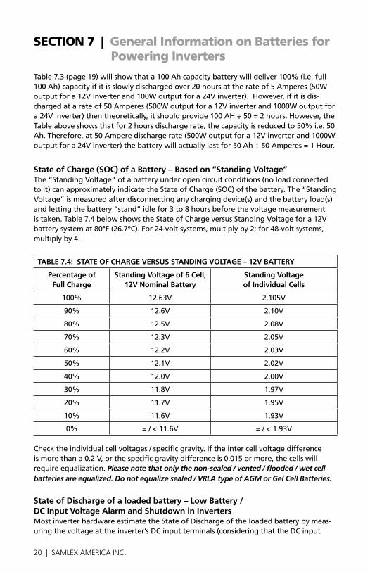
State of charge (Soc) of a Battery – Based on “Standing Voltage” The“StandingVoltage”ofabatteryunderopencircuitconditions(noloadconnectedtoit)canapproximatelyindicatetheStateofCharge(SoC)ofthebattery.The“StandingVoltage”ismeasuredafterdisconnectinganychargingdevice(s)andthebatteryload(s)andlettingthebattery“stand”idlefor3to8hoursbeforethevoltagemeasurementistaken.Table7.4belowshowstheStateofChargeversusStandingVoltagefora12Vbatterysystemat80°f(26.7ºC).for24-voltsystems,multiplyby2;for48-voltsystems,multiply by 4.
tABLe 7.4: StAte oF cHARGe VeRSUS StAnDinG VoLtAGe – 12V BAtteRY
Percentage of Full charge
Standing Voltage of 6 cell, 12V nominal Battery
Standing Voltage of individual cells
100% 12.63V 2.105V
90% 12.6V 2.10V
80% 12.5V 2.08V
70% 12.3V 2.05V
60% 12.2V 2.03V
50% 12.1V 2.02V
40% 12.0V 2.00V
30% 11.8V 1.97V
20% 11.7V 1.95V
10% 11.6V 1.93V
0% =/<11.6V =/<1.93V
Checktheindividualcellvoltages/specificgravity.Iftheintercellvoltagedifferenceismorethana0.2V,orthespecificgravitydifferenceis0.015ormore,thecellswillrequire equalization. Please note that only the non-sealed / vented / flooded / wet cell batteries are equalized. Do not equalize sealed / VRLA type of AGM or Gel Cell Batteries.
State of Discharge of a loaded battery – Low Battery / Dc input Voltage Alarm and Shutdown in invertersMostinverterhardwareestimatetheStateofDischargeoftheloadedbatterybymeas-uringthevoltageattheinverter’sDCinputterminals(consideringthattheDCinput
seCtIOn 7 | General Information on Batteries for Powering Inverters

20 | SAMLEX AMERICA INC. SAMLEX AMERICA INC. | 21
seCtIOn 7 | General Information on Batteries for Powering Inverters
cablesarethickenoughtoallowanegligiblevoltagedropbetweenthebatteryand theinverter).
Inverters are provided with a buzzer alarm to warn that the loaded battery has been deeplydischargedtoaround80%oftheratedcapacity.Normally, the buzzer alarm is triggered when the voltage at the DC input terminals of the inverter has dropped to around 10.5V for a 12V battery or 21V for 24V battery at C-Rate discharge current of C/5 Amps and electrolyte temp. of 80°F. The inverter is shut down if the terminal voltage atC/5dischargecurrentfallsfurtherto10Vfor12Vbattery(20Vfor24Vbattery).
TheStateofDischargeofabatteryisestimatedbasedonthemeasuredterminalvoltageof the battery. The terminal voltage of the battery is dependent upon the following:
- temperature of the battery electrolyte: Temperature of the electrolyte affects the electrochemicalreactionsinsidethebatteryandproducesaNegativeVoltage Coefficient–duringcharging/discharging,theterminalvoltagedropswithriseintemperature and rises with drop in temperature
- the amount of discharging current or “c-Rate”:Abatteryhasnonlinearinternalresistanceandhence,asthedischargecurrentincreases,thebatteryterminalvoltagedecreases non-linearly
Thedischargecurvesinfig.7.1(page19)showthe%StateofChargeversusthetermi-nalvoltageofa12Vbatteryunderdifferentcharge/dischargecurrents,i.e.“C-Rates”andfixedtemperatureof80°f.(PleasenotethattheX-Axisofthecurvesshowsthe%ofStateofCharge.The%ofStateofDischargewillbe100%-%StateofCharge).
Low Dc input Voltage Alarm in invertersAsstatedearlier,thebuzzeralarmistriggeredwhenthevoltageattheDCinputtermi-nalsoftheinverterhasdroppedtoaround10.5Vfora12Vbattery(21Vfor24Vbattery)atC-RatedischargecurrentofC/5Amps.PleasenotethattheterminalvoltagerelativetoaparticularofStateDischargedecreaseswiththeriseinthevalueofthedischargecurrent.forexample,terminalvoltagesforaStateofDischargeof80%(StateofChargeof20%)forvariousdischargecurrentswillbeasfollows(Refertofig.7.1,page19):
Discharge current: c-Rate
terminal Voltage at 80% State of Discharge (20% Soc)
terminal Voltage When completely Discharged (0% Soc)
C/3A 10.45V 09.50V
C/5A 10.90V 10.30V
C/10A 11.95V 11.00V
C/20A 11.85V 11.50V
C/100A 12.15V 11.75V

22 | SAMLEX AMERICA INC.
Intheexamplegivenabove,the10.5VLowBattery/DCInputAlarmwouldtriggerataround80%dischargedstate(20%SoC)whentheC-RatedischargecurrentisC/5Amps.However,forlowerC-RatedischargecurrentofC/10Ampsandlower,thebatterywillbealmost completely discharged when the alarm is sounded. Hence, if the C-Rate dis-charge current is lower than C/5 Amps, the battery may have completely discharged by the time the Low DC Input Alarm is sounded.
Low Dc input Voltage Shut-down in inverters:Asexplainedabove,ataround80%StateofDischargeofthebatteryatC-RatedischargecurrentofaroundC/5Amps,theLowDCInputVoltageAlarmissoundedataround10.5Vfora12Vbattery(ataround21Vfor24Vbattery)towarntheusertodisconnectthebatterytopreventfurtherdrainingofthebattery.Iftheloadisnotdisconnectedatthisstage,thebatterieswillbedrainedfurther to a lower voltage and to a completely discharged condition that is harmful for the battery and for the inverter.
Inverters are normally provided with a protection to shut down the output of the inverteriftheDCvoltageattheinputterminalsoftheinverterdropsbelowathresholdofaround10Vfora12Vbattery(20Vfor24Vbattery).ReferringtotheDischargeCurvesgiveninfig7.1(page19),theStateofDischargeforvariousC-Ratedischargecur-rentsforbatteryvoltageof10Visasfollows:(PleasenotethattheX-Axisofthecurvesshowsthe%ofStateofCharge.The%ofStateofDischargewillbe100%-%StateofCharge):
- 85%StateofDischarge(15%StateofCharge)atveryhighC-ratedischarge currentofC/3Amps.
- 100%StateofDischarge(0%StateofCharge)athighC-Ratedischarge currentofC/5Amps.
- 100%discharged(0%Stateofcharge)atlowerC-rateDischargecurrent ofC/10Amps.
ItisseenthatatDCinputvoltageof10V,thebatteryiscompletelydischargedforC-ratedischargecurrentofC/5andlower.
In view of the above, it may be seen that a fixed Low DC Input Voltage Alarm is not useful.Temperatureofthebatteryfurthercomplicatesthesituation.Alltheaboveanalysisisbasedonbatteryelectrolytetemperatureof80°f.Thebatterycapacityvarieswith temperature. battery capacity is also a function of age and charging history. older batterieshavelowercapacitybecauseofsheddingofactivematerials,sulfation,corro-sion,increasingnumberofcharge/dischargecyclesetc.Hence,theStateofDischargeofabatteryunderloadcannotbeestimatedaccurately.However,thelowDCinputvoltagealarmandshut-downfunctionaredesignedtoprotecttheinverterfromexcessivecur-rent drawn at the lower voltage.
Use of external Programmable Low Voltage Disconnects Theaboveambiguitycanberemovedbyusinganexternal,programmableLowVoltageDisconnectwheremoreexactvoltagethresholdcanbesettodisconnectthebatterybased on the actual application requirements.
seCtIOn 7 | General Information on Batteries for Powering Inverters

22 | SAMLEX AMERICA INC. SAMLEX AMERICA INC. | 23
seCtIOn 7 | General Information on Batteries for Powering Inverters
PleaseconsiderusingthefollowingProgrammableLowBatteryCut-off/“BatteryGuard”ModelsmanufacturedbySamlexAmerica,Inc.www.samlexamerica.com
- BG-40(40A)–forupto400W,12Vinverteror800W,24Vinverter
- BG-60(60A)-forupto600W,12Vinverteror1200W,24Vinverter
- BG-200(200A)-forupto2000W,12Vinverteror4000W,24Vinverter
Depth of Discharge of Battery and Battery LifeThemoredeeplyabatteryisdischargedoneachcycle,theshorterthebatterylife.Usingmorebatteriesthantheminimumrequiredwillresultinlongerlifeforthebatterybank.AtypicalcyclelifechartisgivenintheTable7.5below:
tABLe 7.5: tYPicAL cYcLe LiFe cHARt
Depth of Discharge% of Ah capacity
cycle Life of Group 27 /31
cycle Life of Group 8D
cycle Life of Group Gc2
10 1000 1500 3800
50 320 480 1100
80 200 300 675
100 150 225 550
note:Itisrecommendedthatthedepthofdischargeshouldbelimitedto50%.
Series and Parallel connection of Batteries
Series connection
Fig 7.2: Series Connection
Whentwoormorebatteriesareconnectedinseries,theirvoltagesaddupbuttheirAhcapacityremainsthesame.fig.7.2aboveshows4piecesof6V,200Ahbatteriesconnectedinseriestoformabatterybankof24Vwithacapacityof200Ah.ThePosi-tiveterminalofBattery4becomesthePositiveterminalofthe24Vbank.TheNegativeterminalofBattery4isconnectedtothePositiveterminalofBattery3.TheNegative
6V 6V
Battery 4 Battery 3
6V
Battery 2
6V
Battery 1
24V Inverteror 24V Charger
Cable “A”
Cable “B”

24 | SAMLEX AMERICA INC.
terminalofBattery3isconnectedtothePositiveterminalofBattery2.TheNegativeterminalofBattery2isconnectedtothePositiveterminalofBattery1.TheNegativeter-minalofBattery1becomestheNegativeterminalofthe24Vbatterybank.
Parallel connection
Fig 7.3: Parallel Connection
Whentwoormorebatteriesareconnectedinparallel,theirvoltageremainsthesamebuttheirAhcapacitiesaddup.fig.7.3aboveshows4piecesof12V,100Ahbatteriesconnectedinparalleltoformabatterybankof12Vwithacapacityof400Ah.ThefourPositiveterminalsofBatteries1to4areparalleled(connectedtogether)andthiscom-monPositiveconnectionbecomesthePositiveterminalofthe12Vbank.Similarly,thefourNegativeterminalsofBatteries1to4areparalleled(connectedtogether)andthiscommonNegativeconnectionbecomestheNegativeterminalofthe12Vbatterybank.
Series – Parallel connection
Fig. 7.4: Series-Parallel Connection
figure7.4aboveshowsaseries–parallelconnectionconsistingoffour6V,200AHbat-teriestoforma12V,400Ahbatterybank.Two6V,200Ahbatteries,Batteries1and2
seCtIOn 7 | General Information on Batteries for Powering Inverters
12V 12V 12V 12V
Battery 1 Battery 3Battery 2 Battery 4Cable “A”
Cable “B”
12V Inverteror 12V Charger
6V 6V 6V 6V
12V String 1 12V String 2
Battery 1 Battery 3Battery 2 Battery 4
12V Inverteror 12V Charger
Cable “A”
Cable “B”

24 | SAMLEX AMERICA INC. SAMLEX AMERICA INC. | 25
seCtIOn 7 | General Information on Batteries for Powering Inverters
areconnectedinseriestoforma12V,200Ahbattery(String1).Similarly,two6V,200Ahbatteries,Batteries3and4areconnectedinseriestoforma12V,200Ahbattery (String2).Thesetwo12V,200AhStrings1and2areconnectedinparalleltoforma 12V,400Ahbank.
! cAUtion!When2ormorebatteries/batterystringsareconnectedinparallelandarethenconnectedtoaninverterorcharger(Seefigs7.3and7.4givenabove),attentionshouldbepaidtothemannerinwhichthecharger/inverteriscon-nectedtothebatterybank.PleaseensurethatifthePositiveoutputcableofthebatterycharger/inverter(Cable“A”)isconnectedtothePositivebatterypostofthefirstbattery(Battery1infig7.3)ortothePositivebatterypostofthefirstbatterystring(Battery1ofString1infig.7.4),thentheNegativeout-putcableofthebatterycharger/inverter(Cable“B”)shouldbeconnectedtotheNegativebatterypostofthelastbattery(Battery4asinfig.7.3)ortotheNegativePostofthelastbatterystring(Battery4ofBatteryString2asin fig.7.4).Thisconnectionensuresthefollowing:
- The resistances of the interconnecting cables will be balanced.
- Alltheindividualbatteries/batterystringswillseethesameseriesresistance.
- Alltheindividualbatterieswillcharge/dischargeatthesamecharging currentandthus,willbechargedtothesamestateatthesametime.
- Noneofthebatterieswillseeanoverchargecondition.
Sizing the inverter Battery Bankoneofthemostfrequentlyaskedquestionsis,"howlongwillthebatterieslast?"Thisquestioncannotbeansweredwithoutknowingthesizeofthebatterysystemandtheloadontheinverter.Usuallythisquestionisturnedaroundtoask“Howlongdoyouwantyourloadtorun?”,andthenspecificcalculationcanbedonetodeterminetheproperbatterybanksize.
There are a few basic formulae and estimation rules that are used:
1. ActivePowerinWatts(W)=VoltageinVolts(V)xCurrentinAmperes(A) xPowerfactor
2. foraninverterrunningfroma12Vbatterysystem,theDCcurrentrequiredfromthe12VbatteriesistheACpowerdeliveredbytheinvertertotheloadinWatts(W)dividedby10&foraninverterrunningfroma24Vbatterysystem,theDCcurrentrequiredfromthe24VbatteriesistheACpowerdeliveredbytheinvertertothe loadinWatts(W)dividedby20.
3. Energyrequiredfromthebattery=DCcurrenttobedelivered (A)xtimeinHours(H).

26 | SAMLEX AMERICA INC.
ThefirststepistoestimatethetotalACwatts(W)ofload(s)andforhowlongtheload(s)willoperateinhours(H).TheACwattsarenormallyindicatedintheelectricalnameplateforeachapplianceorequipment.IncaseACwatts(W)arenotindicated,for-mula1givenabovemaybeusedtocalculatetheACwatts.ThenextstepistoestimatetheDCcurrentinAmperes(A)fromtheACwattsasperformula2above.Anexampleofthiscalculationfora12Vinverterisgivenbelow:
Let us say that the total Ac Watts delivered by the 12V inverter = 1000W. Then,usingformula2above,theDCcurrenttobedeliveredbythe12Vbatteries =1000W÷10=100Amperes.
next, the energy required by the load in Ampere Hours (Ah) is determined. forexample,iftheloadistooperatefor3hoursthenasperformula3above,the energytobedeliveredbythe12Vbatteries=100Amperes×3Hours=300AmpereHours(Ah).
now, the capacity of the batteries is determined based on the run time and the usable capacity. fromTable7.3“BatteryCapacityversusRateofDischarge”,theusablecapacityat 3Hourdischargerateis60%.Hence,theactualcapacityofthe12Vbatteriesto deliver300Ahwillbeequalto:300Ah÷0.6=500Ah.
And finally, the actual desired rated capacity of the batteries is determined based on thefactthatnormallyonly80%ofthecapacitywillbeavailablewithrespecttotherated capacity due to non availability of ideal and optimum operating and charging conditions.Sothefinalrequirementswillbeequalto:500Ah÷0.8=625Ah(notethattheactualenergyrequiredbytheloadwas300Ah).
It will be seen from the above that the final rated capacity of the batteries is almost 2timestheenergyrequiredbytheloadinAh.Thus, as a Rule of Thumb, the Ah capacity of the batteries should be twice the energy required by the load in Ah.
fortheaboveexample,the12Vbatteriesmaybeselectedasfollows:
- Use6Group27/31,12V,105Ahbatteriesinparalleltomakeup630Ah,or
- Use3Group8D,12V,225Ahbatteriesinparalleltomakeup675Ah.
seCtIOn 7 | General Information on Batteries for Powering Inverters

26 | SAMLEX AMERICA INC. SAMLEX AMERICA INC. | 27
seCtIOn 8 | Installation
WARninG!
1.Beforecommencinginstallation,pleasereadthesafetyinstructionsexplainedintheSectiontitled“SafetyInstructions”onpage3.
2.Itisrecommendedthattheinstallationshouldbeundertakenbyaqualified,licensed/certifiedelectrician.
3.Variousrecommendationsmadeinthismanualoninstallationwillbesuper-sededbytheNational/LocalElectricalCodesrelatedtothelocationoftheunit and the specific application.
Location of installationPlease ensure that the following requirements are met:
cool:Heatistheworstenemyofelectronicequipment.Hence,pleaseensurethattheunit is installed in a cool area that is also protected against heating effects of direct exposuretothesunortotheheatgeneratedbyotheradjacentheatgeneratingdevices.
Well ventilated: The unit is cooled by convection and by forced air-cooling by tem-peraturecontrolledfans.Thefanssuckcoolairfromairintakeopeningsonthefrontandbottomandexpelhotairthroughtheexhaustopeningsnexttothefans.Toavoidshutdownoftheinverterduetoovertemperature,donotcoverorblocktheseintake/exhaustopeningsorinstalltheunitinanareawithlimitedairflow.Keepaminimumclearanceof10”aroundtheunittoprovideadequateventilation.Ifinstalledinanen-closure,openingsmustbeprovidedintheenclosure,directlyoppositetotheairintakeandexhaustopeningsoftheinverter.
Dry:Thereshouldbenoriskofcondensation,wateroranyotherliquidthatcanenteror fall on the unit.
clean: The area should be free of dust and fumes. ensure that there are no insects or rodents.Theymayentertheunitandblocktheventilationopeningsorshortcircuitelec-trical circuits inside the unit.
Protection against fire hazard: The unit is not ignition protected and should not be locatedunderanycircumstanceinanareathatcontainshighlyflammableliquidslikegasolineorpropaneasinanenginecompartmentwithgasoline-fueledengines.Donotkeepanyflammable/combustiblematerial(i.e.,paper,cloth,plastic,etc.)neartheunitthatmaybeignitedbyheat,sparksorflames.
closeness to the battery bank:Locatetheunitasclosetothebatterybankaspossibletopreventexcessivevoltagedropinthebatterycablesandconsequentpowerlossandreducedefficiency.However,theunitshouldnotbeinstalledinthesamecompartmentasthebatteries(floodedorwetcell)ormountedwhereitwillbeexposedtocorrosiveacidfumesandflammableoxygenandHydrogengasesproducedwhenthebatteriesare charged.

28 | SAMLEX AMERICA INC.
The corrosive fumes will corrode and damage the unit and if the gases are not venti-latedandallowedtocollect,theycouldigniteandcauseanexplosion.
Accessibility:Donotblockaccesstothefrontpanel.Also,allowenoughroomtoaccesstheACreceptaclesandDCwiringterminalsandconnections,astheywillneedtobecheckedandtightenedperiodically.
Preventing Radio Frequency interference (RFi): The unit uses high power switching circuitsthatgenerateRfI.ThisRfIislimitedtotherequiredstandards.Locateanyelec-tronic equipment susceptible to radio frequency and electromagnetic interference as far away from the inverter as possible. Read Section 3, page 11 “Limiting Electromagnetic Interference (EMI)” for additional information.
overall DimensionsThe overall dimensions and the location of the mounting slots are shown in fig.8.1.1and8.1.2(page29).
Mounting orientationTheunithasairintakeandexhaustopeningsforthecoolingfan(s).Ithastobemountedin such a manner so that small objects should not be able to fall easily into the unit from theseopeningsandcauseelectrical/mechanicaldamage.Also,themountingorienta-tionshouldbesuchthatiftheinternalcomponentsoverheatandmelt/dislodgeduetoacatastrophicfailure,themelted/hotdislodgedportionsshouldnotbeabletofalloutof the unit on to a combustible material and cause a fire hazard. The size of openings has been limited as per the safety requirements to prevent the above possibilities when the unit is mounted in the recommended orientations. In order to meet the regulatory safetyrequirements,themountinghastosatisfythefollowingrequirements:
- Mount on a non-combustible material.
- The mounting surface should be able to support the weight of the unit
- Mount horizontally on a horizontal surface - above a horizontal surface (e.g.tabletoporashelf).
- Mount horizontally on a vertical surface – The unit can be mounted on a vertical surface(likeawall)withthefanaxishorizontal(fanopeningfacingleftorright).
WARninG!
MountingtheunitverticallyonaverticalsurfaceisNoTallowed(fanopeningfacingupordown).Asexplainedabove,thisistopreventfallingofobjectsintotheunitthroughthefanopeningwhenthefanopeningfacesup.Iffanopeningfacesdown,hotdam-aged component may fall out. Thesurfaceoftheunitislikelytobeatanelevatedtemperatureinconditionsofhigherloadandhigherambienttemperature.Hence,theunitshouldbeinstalledinamannerwhereitisnotlikelytocomeincontactwithanyperson.
seCtIOn 8 | Installation

28 | SAMLEX AMERICA INC. SAMLEX AMERICA INC. | 29
seCtIOn 8 | Installation
105.6
415
34
107.5
1.2
263
107.5
1.2
52535
19.2
200468.2
5
105
10
Fig. 8.1 PST 1000 & PST 2000: Overall Dimensions and mounting slots.Fig. 8.1: PST-1500 and PST-2000 Overall Dimensions & Mounting Slots (NOTE: Dimensions in mm)

30 | SAMLEX AMERICA INC.
Dc Side connections
Preventing Dc input over VoltageItistobeensuredthattheDCinputvoltageofthisunitdoesnotexceed16.5VDCforthe12-Vbatteryversionsand33.0VDCforthe24-Vbatteryversionstopreventperma-nent damage to the unit. Please observe the following precautions:
- Ensurethatthemaximumchargingvoltageoftheexternalbatterycharger/alterna-tor/solarchargecontrollerdoesnotexceed16.5VDCforthe12Vbatteryversionand33.0VDCforthe24-Vbatteryversion
- Donotuseunregulatedsolarpanelstochargethebatteryconnectedtothisunit. Underopencircuitconditionsandincoldambienttemperatures,theoutputofthesolarpanelmaybe>44VDC.Alwaysuseachargecontrollerbetweenthesolarpaneland the battery.
- WhenusingDiversionChargeControlModeinachargecontroller,thesolar/wind/hydrosourceisdirectlyconnectedtothebatterybank.Inthiscase,thecontrollerwilldivertexcesscurrenttoanexternalload.Asthebatterycharges,thediversiondutycyclewillincrease.Whenthebatteryisfullycharged,allthesourceenergywillflowinto the diversion load if there are no other loads. The charge controller will discon-nectthediversionloadifthecurrentratingofthecontrollerisexceeded.Disconnec-tionofthediversionloadmaydamagethebatteryaswellastheinverterorotherDCloads connected to the battery due to high voltages generated during conditions of highwinds(forwindgenerators),highwaterflowrates(forhydrogenerators).Itis,therefore,tobeensuredthatthediversionloadissizedcorrectlytopreventtheaboveover voltage conditions.
- Donotconnectthisunittoabatterysystemwithavoltagehigherthantheratedbat-teryinputvoltageoftheunit(e.g.donotconnectthe12Vversionoftheunitto24Vor48VBatterySystem)
Preventing Reverse Polarity on the input Side
! cAUtion!Damagecausedbyreversepolarityisnotcoveredbywarranty!Whenmakingbatteryconnectionsontheinputside,makesurethatthepolarityofbatteryconnectionsiscorrect(ConnectthePositiveofthebatterytothePositivetermi-naloftheunitandtheNegativeofthebatterytotheNegativeterminaloftheunit).Iftheinputisconnectedinreversepolarity,DCfuse(s)insidetheinverterwill blow and may also cause permanent damage to the inverter.
connection from the Batteries to the Dc input Side of the Unit – Wire and external Fuse Sizes
WARninG! The input section of the inverter has large capacitors connected across the inputterminals.AssoonastheDCinputconnectionloop(Battery(+)terminal►Externalfuse► Positive input terminal of the inverter ► Negativeinput
seCtIOn 8 | Installation

30 | SAMLEX AMERICA INC. SAMLEX AMERICA INC. | 31
seCtIOn 8 | Installation
terminal of the inverter ► Battery(–)terminal)iscompleted,thesecapacitorswill start charging and the unit will momentarily draw very heavy current that willproducesparkingonthelastcontactintheinputloopevenwhentheoN/off switch on the inverter is in the offposition.Ensurethattheexternalfuseisinserted only after all the connections in the loop have been completed so that thesparkingislimitedtothefusearea.
The flow of electric current in a conductor is opposed by the resistance of the conductor. The resistance of the conductor is directly proportional to the length of the conductor andinverselyproportionaltoitscross-section(thickness).Theresistanceintheconduc-torproducesundesirableeffectsofvoltagedropandheating.Thus,thickerandshorterconductors are desirable.
Thesize(thickness/cross-section)oftheconductorsisdesignatedbyAWG(AmericanWireGauge).PleasenotethatasmallerAWG#denotesathickersizeoftheconductoruptoAWG#1.WiresthickerthanAWG#1aredesignatedAWG1/0,AWG2/0,AWG3/0andsoon.Inthiscase,increasingAWG#denotesthickerwire.
TheDCinputcircuitisrequiredtohandleverylargeDCcurrentsandhence,thesizeofthe wires and connectors should be selected to ensure minimum voltage drop between the battery and the inverter. Thinner wires and loose connections will result in poor inverterperformanceandwillproduceabnormalheatingleadingtoriskofinsulationmeltdownandfire.Normally,thethicknessofthewireshouldbesuchthatthevoltagedrop due to the current & the resistance of the length of the wire should be limited to lessthan5%.Useoilresistant,multi-strandedcopperwireratedat105ºC/221ºf minimum.Donotusealuminumwireasithashigherresistanceperunitlength. Wirescanbeboughtatamarine/weldingsupplystore.
effects of low voltage on common electrical loads are given below:
- Lighting circuits - incandescent and Quartz Halogen:A5%voltagedropcausesanapproximate10%lossinlightoutput.Thisisbecausethebulbnotonlyreceiveslesspower,butthecoolerfilamentdropsfromwhite-hottowardsred-hot,emittingmuchless visible light.
- Lighting circuits - Fluorescent:Voltagedropcausesanearlyproportionaldropin light output.
- Ac induction motors: Thesearecommonlyfoundinpowertools,appliances,wellpumpsetc.Theyexhibitveryhighsurgedemandswhenstarting.Significantvoltagedrop in these circuits may cause failure to start and possible motor damage.
- PV battery charging circuits: These are critical because voltage drop can cause a dis-proportionatelossofchargecurrenttochargeabattery.Avoltagedropgreaterthan5%canreducechargecurrenttothebatterybyamuchgreaterpercentage.
Fuse Protection in Battery circuitsAbatteryisanunlimitedsourceofcurrent.Undershortcircuitconditions,abatterycansupplythousandsofAmperesofcurrent.Ifthereisashortcircuitalongthelengthof

32 | SAMLEX AMERICA INC.
thecablesthatconnectsthebatterytotheinverter,thousandsofAmperesofcurrentcan flow from the battery to the point of shorting and that section of the wire will be-comered-hot,theinsulationwillmeltandthecablewillultimatelybreak.Thisinterrup-tionofveryhighcurrentwillgenerateahazardous,hightemperature,high-energyarcwithaccompanyinghigh-pressurewavethatmaycausefire,damagenearbyobjectsandcause injury. To prevent occurrence of hazardous conditions under short circuit condi-tions,anappropriatefuseshouldbeusedinthebatterycircuitthatwilllimitthecur-rent,blowinaveryshorttimeandquenchthearcinasafemanner.forthispurpose,ULClassTfuseorequivalentwithAmpereInterruptingCapacity(AIC)ofatleast10,000Ashouldbeused(AsperULStandard248-15).Thisspecialpurposecurrentlimiting,veryfastactingfusewillblowinlessthan8msundershortcircuitconditions.AppropriatecapacityoftheaboveClassTfuseshouldbeinstalledwithin7”/178mmofthebatteryPlus(+)Terminal.Thefusewillrequireacorrespondingfuseholder.
WARninG! Useofanappropriatelysizedexternalfuseasdescribedaboveismandatorytoprovide safety against fire hazard due to accidental short circuit in the battery wires.PleasenotethattheDCsidefuse(s)insidetheunitaredesignedtopro-videprotectiontotheinternalcomponentsoftheinverter.ThesefuseswillNoTblow if there is a short circuit along the length of wires connecting the battery and the inverter.
Recommended Sizes of Wires and external FusesTable8.2(page33)providesrecommendedsizingofDCinputwiresandexternalDCinput fuses based on the following considerations:
• CurrentinAmperesaconductorcancarrycontinuouslyundertheconditionsofusewithoutexceedingitstemperatureratingistermedAmpacity(AmpereCapacity).Conductortemperatureratingof105°C/221°f,ambienttemperatureof30°C/86°fand wiring in free air have been considered
• WiresizeisindicatedinAmericanWireGauge(AWG).AWGofastrandedwireisde-termined by the total cross-sectional area of the conductor. note: Because there are also small gaps between the strands, stranded wire with higher number of strands will always have a slightly larger overall diameter than a solid wire / wire with lesser number of strands with the same AWG.
• TheAmpacityoftherecommendedAWGofthewireisequaltoorgreaterthanthedesignedDCinputcurrentattheratedcontinuousoutputpoweroftheinverter.
• Distances3ft.(.91meters)/6ft.(1.83meters)/10ft.(3.05meters)showninTable8.2are the distances between the battery and the inverter. The running length of routing of the wire should be considered if the wiring run is not straight but circuitous.
• RecommendedAWGofwirewillproducemaximumcontinuousvoltagedrop=(DesignedDCinputcurrentattheratedcontinuousoutputpoweroftheinverter)X(Resistanceofthelengthofwire).Lengthofwireisequalto2timesthedistance(tocoverthetotallengthofthePositiveandNegativewires).Table8.1(page33)indi-catesresistanceofwireinohm/ft.at25°C/77°fforcalculatingvoltagedrop.
seCtIOn 8 | Installation

32 | SAMLEX AMERICA INC. SAMLEX AMERICA INC. | 33
note: thicker wire may be selected if lower voltage drop is desired.
table 8.1 Wiring Resistance per Foot
WiRe SiZe ReSiStAnce in oHM / Ft. At 25°c / 77°F
AWG#4 0.0002533
AWG#2 0.0001593
AWG#2/0 0.000077
• AmpereratingoftherecommendedfuseisequaltotheAmpacityofthewire.forsafety against overheating of the wire beyond its rated conductor temperature and consequentpossibilityoffireduetodamagetowireinsulation,theAmpereratingofthefuseshouldnotexceedtheAmpacityofthewire.If,however,exactvalueofstandardsizeoffuseequaltotheAmpacityofthewireisnotavailable,thenexthigher standard size of fuse may be used
• SamlexInverterInstallationKitsarerecommendedforvariousinstallationrequire-mentscoveringbatterytoinverterdistancesofupto10ft.Dependinguponthedis-tancebetweenthebatteryandtheinverter,voltagedropswillvaryasshowninTable8.1.note: For broader suitability, 10 ft. wires are provided with each kit to cover distance of up to 10 ft. to prevent unnecessary voltage drop, cut off excess length of wire that is more than the distance between the battery and inverter. For example, if the distance is 3 ft., use only 3 ft. and cut off the balance 7 ft.
table 8.2 Recommended Sizing of Dc input Wires and external Dc input Fuse
Model no.
Maximum external Fuse Size
Minimum Wire Size
Maximum Voltage DropSamlex America
inverter installation Kit
0.91M / 3 ft.
1.83M / 6 ft.
3.05M / 10 ft.
PST-1500-12 200A AWG#2 1.6% 3.2% 5.3% DC-2000-KIT
PST-1500-24 100A AWG#4 0.6% 1.3% 2.1% DC-1000-KIT
PST-2000-12 300A AWG#2/0 1% 1.8% 3% DC-2500-KIT
PST-200-24 100A AWG#4 0.6% 1.3% 2.1% DC-1000-KIT
Dc input connectionTheDCinputterminalsforbatteryconnection(8&9infig.6.1)havenutandboltconnec-tion-boltsizeis5/16"(18ThreadsperInch).Useringtonguetypeofterminalsonthewireendstofit5/16"boltsize.
Reducing RF interference PleasecomplywithrecommendationsgiveninSection3onpage11-"LimitingElectro-magnetic Interference".
seCtIOn 8 | Installation

34 | SAMLEX AMERICA INC.
Ac SiDe connectionS
WARninG! Preventing Paralleling of the Ac output
1.TheACoutputoftheinvertercannotbesynchronizedwithanotherACsourceandhence,itisnotsuitableforparalleling.TheACoutputofthein-vertershouldneverbeconnecteddirectlytoanelectricalbreakerpanel/loadcenterwhichisalsofedfromtheutilitypower/generator.SuchaconnectionwillresultinparalleloperationandACpowerfromtheutility/generatorwillbefedbackintotheinverterwhichwillinstantlydamagetheoutputsectionof the inverter and may also pose a fire and safety hazard. If an electrical breakerpanel/loadcenterisbeingfedfromtheutilitypower/generatorandtheinverterisrequiredtofeedthispanelasbackuppowersource,theACpowerfromtheutilitypower/generatorandtheinvertershouldfirstbefedtoamanualselectorswitch/AutomaticTransferSwitchandtheoutputofthemanualselectorswitch/AutomaticTransferSwitchshouldbecon-nectedtotheelectricalbreakerpanel/loadcenter.
2.Topreventpossibilityofparallelingandseveredamagetotheinverter,neveruseasimplejumpercablewithamaleplugonbothendstoconnecttheACoutputoftheinvertertoahandywallreceptacleinthehome/RV.
Ac output connection through Ground Fault circuit interrupter (GFci)Anun-intentionalelectricpathbetweenasourceofcurrentandagroundedsurfaceisreferredtoasa“Groundfault”.Groundfaultsoccurwhencurrentisleakingsome-where.Ineffect,electricityisescapingtotheground.Howitleaksisveryimportant.Ifyourbodyprovidesapathtothegroundforthisleakage(dryhumanbodyhasalowresistanceofonlyaround1Kohm),youcouldbeinjured,burned,severelyshockedorelectrocuted.AGroundfaultCircuitInterrupter(GfCI)protectspeoplefromelectricshockbydetectingleakageandcuttingofftheACsource.
TheACoutputofthisinverterisavailablethroughaNEMA5-20RGfCIDuplexReceptacleand also through hardwiring terminal connections located in a compartment behind the GfCIreceptacle(pleaseseefig6.1,Ref#13).TheNeutralslotofthisreceptacle(longerrectangularslot)isinternallybondedtothemetalchassisoftheinverter.
ThereisaGreenindicatorlightthatwillbelightedwhentheGfCIisoperatingnormally.ThelightwillswitchoffiftheGfCIistripped.
TheGfCIisprovidedwiththefollowingbuttons:
- Reset Button:IncasetheGfCIistripped,itcanberesetbypressingthe “ResetButton”.
NoTE:fortheResetButtontooperate,theinverterhastobeinoNcondition.
- test Button:ThisbuttonisusedtotestiftheGfCIisoperatingnormally.TesttheGfCIperiodically to ensure that it is operating normally.
seCtIOn 8 | Installation

34 | SAMLEX AMERICA INC. SAMLEX AMERICA INC. | 35
seCtIOn 8 | Installation
TheGfCIwilltripduetothefollowingconditions:- Leakageorgroundfault- NeutraltoGroundbonding(connection)ontheloadsideoftheGfCI
! cAUtion!
DonotfeedtheoutputfromtheGfCIreceptacletoaBreakerPanel/LoadCenterwheretheNeutralisbondedtotheEarthGround.ThiswilltriptheGfCI.IftheACoutputisrequiredtobefedtoaBreakerPanel/LoadCenter,usehardwiringconnections(pleaseseedetailsgivenbelow).
Ac output connections for HardwiringforconnectingtheACoutputoftheinvertertoanACDistributionPanel/LoadCenter,separateconnectionsareavailableforhardwiring.Pleaserefertofig6.1.Compartment(13)containsterminalsforACoutput.ThecompartmentiscoveredbyCoverPlate(12)withthehelpof4screws.ACoutputconnectionsareasfollows:
Line “L” (15) and neutral “n” (16) terminals. PleasenotethatLineterminal“L”(15)oftheACTerminalBlockandtheLineterminalontheLinesideoftheGfCIareinternallyconnectedtogetheratthePCB.Similarly,Neutralterminal“N”(16)ontheACTerminalBlockandtheNeutralterminalontheLinesideoftheGfCIareinternallyconnectedtogetheratthePCB
• Holediameter:4mm/0.16"• Setscrew:#6(UNf,40ThreadsperInch)orM3.5(CoarsePitch0.6mm)
Ac Ground terminal (14)
• Stud:#6(UNC,32ThreadsPerInch)
neutral to chassis Ground Bonding
• Neutral“N”(16)isbondedtothemetalchassisoftheinverterthroughaloopofwireconnectingthe“N”terminalontheLinesideoftheGfCItothechassisoftheinverter.
WARninG!
RiSK oF eLectRic SHocK. When this unit is installed in vehicles and hard-wiring connectionisusedtofeedtheACoutputoftheinvertertotheACDistributionPanel/LoadCenterinthevehicle,itistobeensuredthatGroundfaultCircuitInterrupter(s)[GfCI]areinstalledinthevehiclewiringsystemtoprotectallBranchCircuits.
ThefollowingGfCIshavebeentestedtooperatesatisfactorilyandareacceptable.othertypes may fail to operate properly when connected to this inverter:
Mfr. of GFci Mfr.’s Model no. Description
Pass & Seymour 2095Series NEMA5-20Duplex20A
Leviton 7899Series NEMA5-20Duplex20A
Zhejiang Trimone TGM20Series NEMA5-20Duplex20A

36 | SAMLEX AMERICA INC.
Ac output cable Sizing & conductor termination for Hard-wiringUse3conductorcablewithatleast90Cinsulationrating.Basedonthemaximumoutputcurrentof12.5AforPST-1500and16.7AforPST-2000,theminimumsizeofeachofthe3conductorsoftheACoutputcableshouldbeAWG#12forboththeinverters.ThisistheminimumsizerecommendedinNECTable310.17forupto20Aovercurrentprotection.forfirmconnectionwhenusingsetscrewtypeofterminals,useInsulatedPinTypeofTerminalsforterminationoftheLineandNeutralconductorsandNonInsulatedRingTypeofTerminalfortheGroundingconductor.forconvenience,thefollowingterminalshavebeenprovided:
For Line and neutral wires:NylonInsulated,CordEnd TerminalsforAWG#12wire ........................................................................ 2 pieces
For neutral wire:NonInsulatedRingTerminalfor#6stud ....................... 1 piece
UsepropercrimpingTooltocrimptheterminalstothebareendsofthewire.Makesurethattheconnectionsaretightandfirm.PleaseensurethattheACcableisadequatelyclampedbythemetalStrainReliefClamp(11).PleaseusethefollowingtypedesignationofACcord:"SE,SEoo,ST,STo,SJ,SJEoo,SJT,orSJTo."
Grounding to earth or to other designated ground forsafety,groundthemetalchassisoftheinvertertotheEarthGroundortotheotherdesignatedground(forexample,inamobileRV,themetalframeoftheRVisnormallydes-ignatedasthenegativeDCground).AnequipmentgroundingLug(7)hasbeenprovidedfor grounding the metal chassis of the inverter to the appropriate ground.
Whenusingtheinverterinabuilding,connecta10mm2orAWG#8insulatedstrandedcopperwirefromtheaboveequipmentgroundinglugtotheEarthGroundconnection(aconnectionthatconnectstotheGroundRodortothewaterpipeortoanotherconnectionthatissolidlybondedtotheEarthGround).Theconnectionsmustbetightagainstbaremetal.Usestarwasherstopenetratepaintandcorrosion.
WhenusingtheinverterinamobileRV,connecta10mm2orAWG#8insulatedstrandedcopper wire from the above equipment grounding lug to the appropriate ground bus of theRV(usuallythevehiclechassisoradedicatedDCgroundbus).Theconnectionsmustbetightagainstbaremetal.Usestarwasherstopenetratepaintandcorrosion.
optional Wired Remote controlAnoptionalWiredRemoteControlModelNo.RC-200(with16.5ft./5metrecable),isavail-ableforswitchingoNandswitchingoff.TheremotehasLCDdisplayshowingACoutputV,A,Hz,W,VAandPowerfactor.ItalsohasLEDindicationssimilartotheindicationsonthefrontpanel(2,3,4infig.6.1).ReadRemoteControlManualfordetails.
Powering on the LoadsAftertheinverterisswitchedon,ittakesafinitetimetobecomereadytodeliverfullpower.Hence,alwaysswitchontheload(s)afterafewsecondsofswitchingontheinverter.Avoidswitching on the inverter with the load already switched on. This may prematurely trigger the overload protection.
Whenaloadisswitchedon,itmayrequireinitialhigherpowersurgetostart.Hence,ifmul-tipleloadsarebeingpowered,theyshouldbeswitchedononebyonesothattheinverterisnot overloaded by the higher starting surge if all the loads are switched on at once.
seCtIOn 9 | Operation

36 | SAMLEX AMERICA INC. SAMLEX AMERICA INC. | 37
seCtIOn 9 | Operation
Switching the inverter on/oFFBeforeswitchingontheinverter,checkthatalltheACloadshavebeenswitchedoff.TheoN/offswitch(1)onthefrontpaneloftheinverterisusedtoswitchonandswitchofftheinverter.Thisswitchoperatesalowpowercontrolcircuitry,whichinturncontrolsallthehighpowercircuitry.optionalRemoteControlModelRC-200mayalsobeusedforoN/offcontrol.
! cAUtion! Please note that the oN/off switch is not switching the high power batteryinputcircuit.PartsoftheDCsidecircuitwillstillbealiveevenwhentheswitchisinthe offposition.Hence,disconnecttheDCandACsidesbeforeworkingonanycircuitscon-nected to the inverter.
When the inverter is switched oN,theGREEN"PoweroN"LED(2,fig.6.1)willbelighted.ThisLEDindicatesthattheinputsectionoftheinverterisoperatingnormally.Undernormaloperatingconditions,ACoutputvoltagewillnowbeavailableattheGfCIDuplexRecepta-cle(5).TheGreenindicatorlightontheGfCIwillbelighted.
SwitchontheACload(s).The GREEN"PoweroN"LED(2)andtheindicationlightontheGfCIshouldremainlightedfornormaloperationoftheload.
temperature controlled cooling FansTwo cooling fans are thermostatically controlled. Temperature of a critical hot spot inside the inverter is monitored to activate the fans and the over temperature shut-down. When thetemperatureofthishotspotreaches118.4°f/48°C,thefansareswitchedoN. The fans will be automatically switched offoncethehotspotcoolsdownto107.6°f/42°C.Pleasenote that the fans may not come on at low loads or if the ambient temperature is cooler. This is normal.
indications For normal operationWhentheinverterisoperatingnormallyandsupplyingACload(s),theGREEN"PoweroN"LED(2)andtheindicationlightontheGfCIwillbelighted.Please see under "Protection Against Abnormal Conditions" and "Troubleshooting Guide" for symptoms of abnormal operation.
no Load Draw (idle current) When the oN/offswitchisturnedon,allthecircuitryinsidetheinverterbecomesaliveandtheACoutputismadeavailable.Inthiscondition,evenwhennoloadisbeingsupplied(or,ifaloadisconnectedbuthasbeenswitchedoff),theinverterdrawsasmallamountofcurrentfromthebatteriestokeepthecircuitryaliveandreadytodelivertherequiredpowerondemand.Thisiscalledthe"idlecurrent"orthe"noloaddraw".Hence,whentheloadisnotrequiredtobeoperated,turnoff the oN/off switch on the inverter to prevent unnecessary current drain from the battery.
i
inFo
WhentheinverteristurnedoffusingtheoptionalRemoteControlRC-200,some control circuitry in the inverter is still alive and will draw very low current. Therefore,topreventanydrainfromthebattery,switchofftheinverterfromtheoN/offswitchprovidedonthefrontpaneloftheinverter.

38 | SAMLEX AMERICA INC.
seCtIOn 10 | Protections
The inverter has been provided with protections detailed below:
overload / Short circuit Shut Down Theinvertercanprovidehigherthannormalinstantaneouspower(<1second)limitedtothesurgepowerratingoftheinverter.Also,theinvertercanprovidecontinuouspower limited to the continuous power rating of the inverter. If there is an overload beyondthesespecifiedlimits,theACoutputoftheunitwillbeshutdownpermanently.REDLEDmarked"overload"willturnoN,theGREENindicationontheGfCIwillbeoffandbuzzeralarmwillsound.TheGREEN"PoweroN"LED(2)willcontinuetobelighted. The unit will be latched in this shutdown condition and will require manual reset.Toreset,switchoff the power oN/offswitch,waitfor3minutesandthenswitchoN again. before switching oNagain,removethecauseoftheshutdown.
Warning Alarm - Low Dc input Voltage ThevoltageattheDCinputterminalswillbelowerthanthevoltageatthebatteryter-minals due to voltage drop in the battery wires and connectors. The drop in the voltage attheDCinputterminalsoftheinvertercouldbeduetolowerbatteryvoltageorduetoabnormallyhighdropinthebatterywiresifthewiresarenotthickenough(Please see page 31 “Connection From the Batteries To the DC Input Side of The Unit – Wire and External Fuse Sizes”).IfthevoltageattheDCinputterminalsfallsbelow10.5Vfor12Vversionsor21.0Vfor24Vversions,abuzzeralarmwillbesounded.TheGREEN"PoweroN"LED(2)andindicationlightontheGfCIwillcontinuetobelightedandtheACoutput voltage would continue to be available. This warning buzzer alarm indicates that the battery is running low and that the inverter will be shut down after sometime if the voltageattheinverterterminalsfurtherdropsto10Vfor12Vversionsor20Vfor24Vversions.
Low Dc input Voltage Shut Down IfthevoltageattheDCinputterminalsfallsbelow10Vfor12Vversionsor20Vfor24Vversions,theACoutputisshutdown.Buzzeralarmissounded.TheGREEN"PoweroN" LED(2)willremainlighted.TheGREENindicationlightontheGfCIwillbeoff. TheunitwillresetautomaticallywhentheDCinputvoltagerises>11.5Vfor12Vver-sionsand>23Vfor24Vversions
High Dc input Voltage ShutdownIfthevoltageattheDCinputterminalsexceeds16.5Vfor12Vversionsor33Vfor 24Vversions,theinverterwillbeshutdowntemporarily.Buzzeralarmwillbesounded.TheGREEN"PoweroN"LED(2)willremainlighted.TheGREENindicatorlightontheGfCIwillbeoff.Theunitwillberesetautomaticallywhenthevoltagedropsdownto <16.5Vfor12Vversionsandto<33Vfor24Vversions.

38 | SAMLEX AMERICA INC. SAMLEX AMERICA INC. | 39
over-temperature Shut Down In case of failure of the cooling fans or in the case of inadequate heat removal due to higherambienttemperatures/insufficientairexchange,thetemperatureinsidetheunit will increase. The temperature of a critical hot spot inside the inverter is monitored andat203°f/95°C,theACoutputoftheinverterisshutdowntemporarily.Buzzeralarmwillbesounded.TheGREEN"PoweroN"LED(2)willremainlighted.TheGREENindicationlightontheGfCIwillbeoff.
Theunitwillautomaticallyresetafterthehotspothascooleddownto158°f/70°C.
internal Dc Side FusesThefollowingDCsidefuseshavebeenprovidedforinternalprotectionoftheDCinputside.Thefusesare32V,AutomotiveTypeBladefuses,Type"ATC"byCooperBussmannor equivalent:
PST-1500-12:5piecesof40Ainparallel=200Atotal
PST-1500-24:5piecesof20Ainparallel=100Atotal
PST-2000-12:6piecesof40Ainparallel=240Atotal
PST-2000-24:6piecesof20Ainparallel=120Atotal
Reverse Polarity at the Dc input terminalsThePositiveofthebatteryshouldbeconnectedtothePositiveDCinputterminaloftheinverterandtheNegativeofthebatteryshouldbeconnectedtotheNegativeDCinputterminaloftheinverter.Areversalofpolarity(thePositiveofthebatterywronglycon-nectedtotheNegativeDCinputterminaloftheinverterandtheNegativeofthebat-terywronglyconnectedtothePositiveDCinputterminaloftheinverter)willblowtheexternal/internalDCsidefuses.IftheDCsidefuseisblown,theinverterwillbedead.TheStatusLED(2)andtheGREENindicationlightontheGfCIwillbeswitchedoff and therewillbenoACoutput.
i inFo
ReversepolarityconnectionislikelytodamagetheDCinputcircuitry.Theinternalfuse(s)shouldbereplacedwiththesamesizeoffuse(s)usedintheunit.Iftheunitdoesnotworkafterreplacingthefuse(s),ithasbeenpermanentlydamagedandwillrequirerepair/replacement (Please read Section 11 - “Troubleshooting Guide” for more details).
! cAUtion!Damagecausedbyreversepolarityisnotcoveredbywarranty!Whenmakingbatteryconnectionsontheinputside,makesurethatthepolarityofbatteryconnectionsiscorrect(ConnectthePositiveofthebatterytothePositiveterminaloftheunitandtheNegativeofthebatterytotheNegativeterminaloftheunit).Iftheinputisconnectedinreverse polarity,DCfuse(s)insidetheinverter/externalfusewillblowandmayalsocause permanent damage to the inverter.
seCtIOn 10 | Protections

40 | SAMLEX AMERICA INC.
seCtIOn 11 | trouble shooting Guide
iSSUe PoSSiBLe cAUSe ReMeDY
When switched ON, The GREEN "Power ON"LED (2) does not light. Buzzer is Off. There is no AC output volt-age. GREEN indication light on the GfCI is Off.
There is no voltage at the DC input terminals / 12V power outlet in the vehicle
Check the continuity of the battery input circuit.
Check that the internal/external battery fuse/vehicle fuse for 12V power outlet is intact. Replace if blown. When powered from 12V power outlet in the vehicle, ensure that the AC load is less than 150W.
Check that all connections in the battery input circuit are tight.
Polarity of the DC input voltage has been reversed that has blown the exter-nal / internal DC side fuses (Note:Reversepolaritymay cause permanent damage).
Check external and internal fuses. Internal fuses may be soldered and may not be easily replaceable. Replace fuses. If unit does not work, call Technical Support for repair.
Low AC output voltage (No buzzer alarm).
Low input voltage at the inverter terminals and the load is close to the maxi-mum allowable power.
Check that the battery is fully charged. Re-charge, if low.
Check that the battery cables are thick enough to carry the required current over the required length. Use thicker cables, if required.
Tighten connections of battery input circuit.
Reduce load.
Buzzer alarm is sounded when load is switched ON. Voltage at DC input terminals reads between 10 to 10.5V for 12V versions and between 20 to 21.0V for 24V versions. The GREEN "Power ON" LED (2) is lighted. Indication light on the GfCI is GREEN. AC output voltage is available.
DC input voltage is less than 10.5V for 12V versions and less than 21.0V for 24V versions.
Check that the battery is fully charged. Re-charge, if low.
Check that the battery cables are thick enough to carry the required current over the required length. Use thicker cables, if required.
Tighten connections of the battery input circuit.
Buzzer alarm is sounded when load is switched ON. Voltage at the DC input terminals reads below 10V for 12V versions and below 20V for 24V versions. The GREEN "Power ON" LED (2) is lighted. GREEN indication light on the GfCI is Off. There is no AC output.
Shut-down due to low DC input voltage - Less than 10V for 12V versions and less than 20V for 24V versions.
Check that the battery is fully charged. Re-charge, if low.
Check that the battery cables are thick enough to carry the required current over the required length. Use thicker cables, if required.
Tighten connections of the battery input circuit.

40 | SAMLEX AMERICA INC. SAMLEX AMERICA INC. | 41
iSSUe PoSSiBLe cAUSe ReMeDY
There is no AC output. The GREEN "Power ON" LED (2) is lighted. Buzzer is ON. GREEN indication light on the GfCI is Off.
Shut-down due to high input DC voltage –
> 16.5V for 12V versions and > 33V for 24V versions.
Check that the voltage at the DC input termi-nals is less than 16.5V for 12V versions and less than 33V for 24V versions.
Ensure that the maximum charging voltage of the battery charger / alternator / solar charge controller is below 16.5V for 12V versions and below 33V for 24V versions.
Ensure that an unregulated solar panel is not used to charge a battery. Under cold ambient temperatures, the output of the solar panel may exceed 22V for 12V system or 42V for 24 V system. Ensure that a charge controller is used between the solar panel and the battery.
AC output shuts down com-pletely. Red "Overload" LED (3) is lighted. Buzzer is ON. The GREEN "Power ON" LED (2) is lighted. GREEN indica-tion light on the GfCI is Off.
Permanent shut-down of the AC output due to con-tinuous overload beyond the continuous power rating of the inverter.
Reduce the load.
The load is not suitable as it requires higher power to operate. Use an inverter with higher power rating.
If the unit goes into permanent overload again after resetting and removing the load com-pletely, the unit has become defective. Call Technical support.
note: The unit will be latched in this shut-down condition and will require manual reset.
To reset, switch Off the power ON/Off switch, wait for 3 minutes and then switch ON again.
Before switching on again, remove the cause of the shut-down.
There is no AC output. Buzzer alarm is sounded. Red "Over temperature" LED (4) is lighted. The GREEN "Power ON LED (2) is lighted. GREEN indication light on the GfCI is Off.
Shut-down due to over temperature because of fan failure or inadequate cooling as a result of high ambient temperature or insufficient air exchange
Check that the fans are working. If not, the fan control circuit may be defective. Call Technical Support.
If the fans are working, check that the ventila-tion slots on the suction side and the openings on the discharge side of the fans are not obstructed.
If the fans are working and the openings are not obstructed, check that enough cool replacement air is available. Also check that the ambient air temperature is less than 40ºC.
Reduce the load to reduce the heating effect.
After the cause of overheating is removed and the unit cools down sufficiently, it will reset automatically.
There is no AC output. GREEN indication on the GfCI is Off. The GREEN "Power ON" LED (2) is lighted. No buzzer alarm.
GfCI has tripped due to leakaage or due to Neutral to Ground bond on the load side.
Check load side circuits for leakage or Neutral to Ground bonding and correct. Press "Reset Button" on the GfCI to reset. Ensure that the inverter is ON before re-setting.
seCtIOn 11 | trouble shooting Guide

42 | SAMLEX AMERICA INC.
seCtIOn 12 | specifications
MoDeL no. PSt-1500-12 PSt-1500-24oUtPUt
oUTPUTVoLTAGE 120VAC±3% 120VAC±3%MAXIMUMoUTPUTCURRENT 12.5A 12.5A
oUTPUTfREQUENCY 60Hz±1% 60Hz±1%
TYPEofoUTPUTWAVEfoRM Pure Sine Wave Pure Sine WaveToTALHARMoNICDISToRTIoNof
oUTPUTWAVEfoRM<3% <3%
CoNTINUoUSoUTPUTPoWER(AtPowerfactor=1) 1500 Watts 1500 Watts
SURGEoUTPUTPoWER(AtPowerfactor=1;<1sec) 3000Watts 3000Watts
PEAKEffICIENCY(Atfullload) 85% 85%
ACoUTPUTCoNNECTIoNS(i)NEMA5-20RGfCIDuplexReceptacle(ii)Terminalblockforhardwiring:Hole diameter(4mm/0.16") & Set Screw(#6x40TPIorM3.5x0.6mmPitch)
inPUt
NoMINALDCINPUTVoLTAGE 12V 24VDCINPUTVoLTAGERANGE 10.7-16.5VDC 21.4-33VDC
MAXIMUMINPUTCURRENT 200A 100A
DCINPUTCURRENTATNoLoAD 1.0A 0.8A
DCINPUTCoNNECTIoNS Bolt&nut:5/16"x18TPI
DCINPUTfUSES(INTERNAL) 5X40A=200A(EachTypeATC,32V,40A)
5x20A=100A(EachTypeATC,32V,20A)
LeD DiSPLAY Power,overload,overTemperature
PRotectionS
LoWDCINPUTVoLTAGEALARM 10.7V 21.4VLoWDCINPUTVoLTAGESHUTDoWN 10V 20V
HIGHDCINPUTVoLTAGESHUTDoWN 16.5V 33V
SHoRTCIRCUITSHUTDoWN Yes Yes
oVERLoADSHUTDoWN Yes Yes
GRoUNDfAULTSHUTDoWN Yes Yes
oVERTEMPERATURESHUTDoWN Yes YesREVERSEPoLARITYoNDCINPUTSIDE Yes Yes
WiReD ReMote contRoL (oPtionAL) RC-200(Soldseparately)
FoRceD AiR cooLinG 2TemperatureControlledfans
coMPLiAnce
SAfETY Intertek-ETLListed.ConformstoANSI/UL Standard458.
EMI/EMC fCCPart15(B),ClassB
enViRonMent
oPERATINGTEMPERATURERANGE 32°f to 104°f/ 0to40˚CDiMenSionS AnD WeiGHtS
(LXWXH),MM 468.2x263x105.6 468.2x263x105.6(LXWXH),INCHES 18.43x10.35x4.16 18.43x10.35x4.16
KG 7.1 7.1
LBS 15.6 15.6
See Specification Table Cautions (page 43)

42 | SAMLEX AMERICA INC. SAMLEX AMERICA INC. | 43
! cAUtion! RiSK oF FiRe
Donotreplaceanyvehiclefusewitharatinghigherthanrecommendedby thevehiclemanufacturer.Thisproductisratedtodraw200Amperesfrom12Vbatteryvehicleoutletand100Amperesfrom24Vbatteryvehicleoutlet.Ensurethat the electrical system in your vehicle can supply this product without caus-ingthevehiclefusingtoopen.Thiscanbedeterminedbymakingsurethatthefuseinthevehicle,whichprotectstheoutlet,isratedhigher200amperes(12Vbattery),or100amperes(24Vbattery).Informationonthevehiclefuseratingsis typically found in the vehicle operator's manual. If a vehicle fuse opens re-peatedly,donotkeeponreplacingit.Thecauseoftheoverloadmustbefound.on no account should fuses be patched up with tin foil or wire as this may cause serious damage elsewhere in the electrical circuit or cause fire.
seCtIOn 12 | specifications

44 | SAMLEX AMERICA INC.
seCtIOn 12 | specifications
MoDeL no. PSt-2000-12 PSt-2000-24oUtPUt
oUTPUTVoLTAGE 120VAC±3% 120VAC±3%MAXIMUMoUTPUTCURRENT 16.7A 16.7A
oUTPUTfREQUENCY 60Hz±1% 60Hz±1%
TYPEofoUTPUTWAVEfoRM Pure Sine Wave Pure Sine WaveToTALHARMoNICDISToRTIoNof
oUTPUTWAVEfoRM<3% <3%
CoNTINUoUSoUTPUTPoWER(AtPowerfactor=1) 2000 Watts 2000 Watts
SURGEoUTPUTPoWER(AtPowerfactor=1;<1sec) 3500Watts 3500Watts
PEAKEffICIENCY(Atfullload) 85% 85%
ACoUTPUTCoNNECTIoNS(i)NEMA5-20RGfCIDuplexReceptacle(ii)Terminalblockforhardwiring:Hole diameter(4mm/0.16") & Set Screw(#6x40TPIorM3.5x0.6mmPitch)
inPUt
NoMINALDCINPUTVoLTAGE 12V 24VDCINPUTVoLTAGERANGE 10.7-16.5VDC 21.4-33VDC
MAXIMUMINPUTCURRENT 240A 120A
DCINPUTCURRENTATNoLoAD <1.0A <0.8A
DCINPUTCoNNECTIoNS Bolt&nut:5/16"x18TPI
DCINPUTfUSES(INTERNAL) 6X40A=240A(EachTypeATC,32V,40A)
6x20A=120A(EachTypeATC,32V,20A)
LeD DiSPLAY Power,overload,overTemperature
PRotectionS
LoWDCINPUTVoLTAGEALARM 10.7V 21.4VLoWDCINPUTVoLTAGESHUTDoWN 10V 20V
HIGHDCINPUTVoLTAGESHUTDoWN 16.5V 33V
SHoRTCIRCUITSHUTDoWN Yes Yes
oVERLoADSHUTDoWN Yes Yes
GRoUNDfAULTSHUTDoWN Yes Yes
oVERTEMPERATURESHUTDoWN Yes YesREVERSEPoLARITYoNDCINPUTSIDE Yes Yes
WiReD ReMote contRoL (oPtionAL) RC-200(Soldseparately)
FoRceD AiR cooLinG 2TemperatureControlledfans
coMPLiAnce
SAfETY Intertek-ETLListed.ConformstoANSI/UL Standard458.
EMI/EMC fCCPart15(B),ClassB
enViRonMent
oPERATINGTEMPERATURERANGE 32°f to 104°f/ 0to40˚CDiMenSionS AnD WeiGHtS
(LXWXH),MM 468.2x263x105.6 468.2x263x105.6(LXWXH),INCHES 18.43x10.35x4.16 18.43x10.35x4.16
KG 7.1 7.1
LBS 15.6 15.6
See Specification Table Cautions (page 45)

44 | SAMLEX AMERICA INC. SAMLEX AMERICA INC. | 45
seCtIOn 12 | specifications
! cAUtion! RiSK oF FiRe
Donotreplaceanyvehiclefusewitharatinghigherthanrecommendedby thevehiclemanufacturer.Thisproductisratedtodraw240Amperesfrom12Vvehicleoutletand120Amperesfrom24Vbatteryvehicleoutlet.Ensurethattheelectricalsys-tem in your vehicle can supply this product without causing the vehicle fusing to open. Thiscanbedeterminedbymakingsurethatthefuseinthevehicle,whichprotectstheoutlet,isratedhigher240amperes(12Vbattery),or120amperes(24Vbattery).Infor-mation on the vehicle fuse ratings is typically found in the vehicle operator's manual. If avehiclefuseopensrepeatedly,donotkeeponreplacingit.Thecauseoftheoverloadmust be found. on no account should fuses be patched up with tin foil or wire as this may cause serious damage elsewhere in the electrical circuit or cause fire.

46 | SAMLEX AMERICA INC.
seCtIOn 13 | warranty
2 YeAR LiMiteD WARRAntY
ThePST-1500-12,PST-1500-24,PST-2000-12andPST-2000-24aremanufacturedbySamlexAmerica,Inc.(the“Warrantor“)iswarrantedtobefreefromdefectsinworkmanshipand materials under normal use and service. The warranty period is 2 years for the UnitedStatesandCanada,andisineffectfromthedateofpurchasebytheuser(the“Purchaser“).
WarrantyoutsideoftheUnitedStatesandCanadaislimitedto6months.forawarrantyclaim,thePurchasershouldcontacttheplaceofpurchasetoobtainaReturnAuthoriza-tionNumber.
ThedefectivepartorunitshouldbereturnedatthePurchaser’sexpensetotheauthor-izedlocation.Awrittenstatementdescribingthenatureofthedefect,thedateofpur-chase,theplaceofpurchase,andthePurchaser’sname,addressandtelephonenumbershould also be included.
IfupontheWarrantor’sexamination,thedefectprovestobetheresultofdefectivematerialorworkmanship,theequipmentwillberepairedorreplacedattheWarran-tor’soptionwithoutcharge,andreturnedtothePurchaserattheWarrantor’sexpense.(ContiguousUSandCanadaonly)
NorefundofthepurchasepricewillbegrantedtothePurchaser,unlesstheWarrantoris unable to remedy the defect after having a reasonable number of opportunities to do so.WarrantyserviceshallbeperformedonlybytheWarrantor.Anyattempttoremedythe defect by anyone other than the Warrantor shall render this warranty void. There shallbenowarrantyfordefectsordamagescausedbyfaultyinstallationorhook-up,abuseormisuseoftheequipmentincludingexposuretoexcessiveheat,saltorfreshwaterspray,orwaterimmersion.
Nootherexpresswarrantyisherebygivenandtherearenowarrantieswhichextendbeyondthosedescribedherein.Thiswarrantyisexpresslyinlieuofanyotherexpressedorimpliedwarranties,includinganyimpliedwarrantyofmerchantability,fitnessfortheordinarypurposesforwhichsuchgoodsareused,orfitnessforaparticularpurpose,orany other obligations on the part of the Warrantor or its employees and representatives.
There shall be no responsibility or liability whatsoever on the part of the Warrantor or itsemployeesandrepresentativesforinjurytoanypersons,ordamagetopersonorpersons,ordamagetoproperty,orlossofincomeorprofit,oranyotherconsequentialor resulting damage which may be claimed to have been incurred through the use or saleoftheequipment,includinganypossiblefailureofmalfunctionoftheequipment,or part thereof. The Warrantor assumes no liability for incidental or consequential dam-agesofanykind.
Samlex America inc. (the “Warrantor”)www.samlexamerica.com

46 | SAMLEX AMERICA INC. SAMLEX AMERICA INC. | 47
nOtes:

Contact Information
Toll Free NumbersPh: 800 561 5885
Fax: 888 814 5210
Local NumbersPh: 604 525 3836
Fax: 604 525 5221
Websitewww.samlexamerica.com
USA Shipping WarehouseKent WA
Canadian Shipping WarehouseDelta BC
Email purchase orders [email protected]
11001-PST-1500-2000-12-24-0513