owner's operating - middleby | the middleby … (g… · ctx owner's operating &...
TRANSCRIPT
CTX OWNER'S OPERATING
& INSTALLATION
MANUAL
G-26 CONVEYOR OVEN
CTX® • 1400 Toastmaster Drive • Elgin, IL 60120 • (708}741-3300 • FAX (708}741-0015 A Middleby Company
Middleby Corporation 24 Hour Service Hotline 1-800-238-8444 Part No. 310-2547
Price $15.00 p 5/93
CTX® OVEN LIMITED WARRANTY
The seller warrants equipment manufactured by it to be free from defects in material and workmanship for which it is responsible. The Seller's obligation under this warranty shall be limited to replacing or repairing at Seller's option, without charge, F.O.B. Seller's factory, any part found to be defective and any labor and material expense incurred by Seller in repairing or replacing such part, such warranty to be limited to a period of one (1) year from date of original installation or eighteen (18) months from date of shipment from Seller's factory, whichever is earlier, provided that terms of payment have been fully met. All labor shall be performed during regular working hours. Overtime premium will be charged to the Buyer.
THIS WARRANTY IS NOT VALID UNLESS EQUIPMENT IS STARTED AND DEMONSTRATED UNDER THE SUPERVISION OF A FACTORY CERTIFIED INSTALLER.
Normal maintenance functions, including lubrication, thermostat calibration, and replacement of light bulbs, fuses and indicating lights, are not covered by warranty.
Any repairs or replacements of defective parts shall be performed by Seller's authorized service personnel. Seller shall not be responsible for any costs incurred if the work is performed by other than Seller's authorized service personnel.
When returning any part under warranty, the part must be intact and complete, without evidence of misuse or abuse, freight prepaid.
This warranty is made to the original purchaser/user and is not transferable.
Seller shall not be liable for consequential damages of any kind which occur during the course of installation of equipment, or which result from the use or misuse by Buyer, its employees or others of the equipment supplied hereunder, and Buyer's sole and exclusive remedy against Seller for any breach of the foregoing warranty or otherwise shall be for the repair or replacement of the equipment or parts thereof affected by such breach. ·
The foregoing warranty shall be valid and binding upon Seller if and only if Buyer loads, operates and maintains the equipment supplied hereunder in accordance with the instruction manual provided to Buyer. Seller does not guarantee the process of manufacture by Buyer or the quality of product to be produced by the equipment supplied hereunder and Seller shall not be liable for any prospective or lost profits of Buyer.
THE FOREGOING WARRANTY IS EXCLUSIVE AND IN LIEU OF ALL OTHER EXPRESS AND IMPLIED WARRANTIES WHATSOEVER. SPECIFICALLY THERE ARE NO IMPLIED WARRANTIES OF MERCHANTABILITY OR OF FITNESS FOR A PARTICULAR PURPOSE.
The foregoing shall be Seller's sole and exclusive obligation and Buyer's sole and exclusive remedy for any action, whether in breach of contract or negligence. In no event shall seller be liable for a sum in excess of the purchase price of the item.
© 1993 CTX
CTX® • 1400 Toastmaster Dr. • Elgin, IL 60120-9272 • (708) 741-3300 • FAX (708) 741-0015
RETAIN THIS MANUAL FOR FUTURE Rt:FERENCE
This manual provides detailed information for installation and operation of your new Gemini Series oven. It also contains some information to assist the operator in diagnosing problems in the event of a malfunction. This manual is an important tool for the operator and should be kept readily available.
FOR YOUR SAF'ETY DO NOT STORE OR USE GASOLINE
OR OTHER FLAMMABLE VAPORS OR LIQUIDS IN THE VICINITY OF THIS OR ANY OTHER APPLIANCE
NOTICE Using any parts other than
genuine CTX factory manufactured parts relieves the
manufacturer of all liability.
NOT'IC:E CTX (Manufacturer) reserves the right to
change specifications and product design without notice. Such revisions do not entitle
the buyer to corresponding changes, Improvements, additions or replacements for
previously purchased equipment.
ii
~ j i
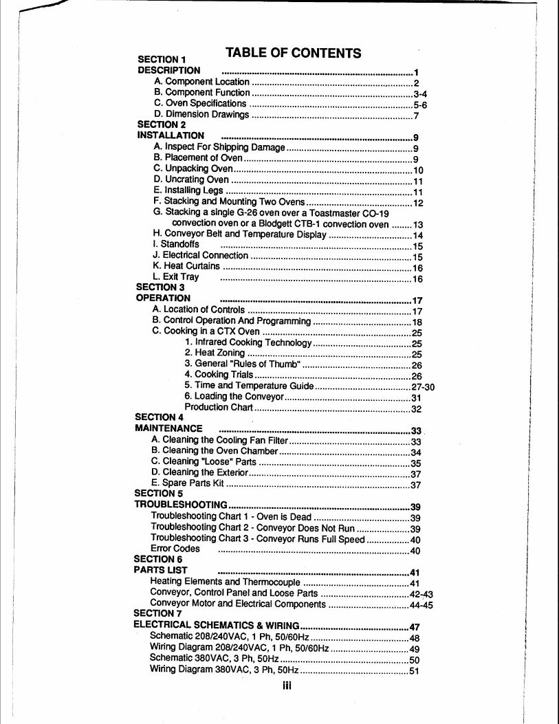
SECTION 1 TABLE OF CONTENTS DESCRIPTION •••••••••••••••••..••••••••...••••••.•..•••••••.•••.•••....••••••••••.••••.. 1
A. Component Location ................................................................ 2 B. Component Function ................................................................ 3-4 C. Oven Specifications ................................................................. 5-8 D. Dimension Drawings ................................................................ 7
SECTION 2 INSTALLATION ............................................................................ 9
A. Inspect For Shipping Damage .................................................. 9 B. Placement of Oven ................................................................... 9 C. Unpacking Oven ....................................................................... 10 D. Uncrating Oven ........................................................................ 11 E. Installing Legs .......................................................................... 11 F. Stacking and Mounting Two Ovens .......................................... 12 G. Stacking a single G-26 oven over a Toastmaster C0-19
convection oven or a Blodgett CTB-1 convection oven ........ 13 H. Conveyor Belt and Temperature Display ................................. 14 I. Standoffs ............................................................................ 15 J. Electrical Connection ................................................................ 15 K. Heat Curtains ........................................................................... 16 L. Exit Tray ............................................................................ 16
SECTION 3 OPERATION ............................................................................ 17
A. Location of Controls ................................................................. 17 B. Control Operation And Programming ....................................... 18 C. Cooking in a CTX Oven ........................................................... 25
1. Infrared Cooking Technology ....................................... 25 2. Heat Zoning ................................................................. 25 3. General "Rules of Thumb" ........................................... 26 4. Cooking Trials .............................................................. 26 5. Time and Temperature Guide ...................................... 27-30 6. Loading the Conveyor .................................................. 31 Production Chart .............................................................. 32
SECTION 4 MAINTENANCE ............................................................................ 33 .
A. Cleaning the Cooling Fan Filter ................................................ 33 B. Cleaning the Oven Chamber .................................................... 34 C. Cleaning "Loose" Parts ............................................................ 35 D. Cleaning the Exterior ................................................................ 37 E. Spare Parts Kit ......................................................................... 37
SECTIONS TROUBLESHOOTING ••••••.••••••..•••••..•••.••.•..•••.•.•.•••••...•••....••••....••••••••• 39
Troubleshooting Chart 1 -Oven is Dead ...................................... 39 Troubleshooting Chart 2 - Conveyor Does Not Run ..................... 39 Troubleshooting Chart 3 - Conveyor Runs Full Speed ................. 40 Error Codes ............................................................................ 40
SECTION 6 PARTS LIST ............................................................................ 41
Heating Elements and Thermocouple ......................................... .41 Conveyor, Control Panel and Loose Parts ................................... 42-,43 Conveyor Motor and Electrical Components ................................ 44-45
SECTION 7 ELECTRICAL SCHEMATICS & WIRING ........................................... 47
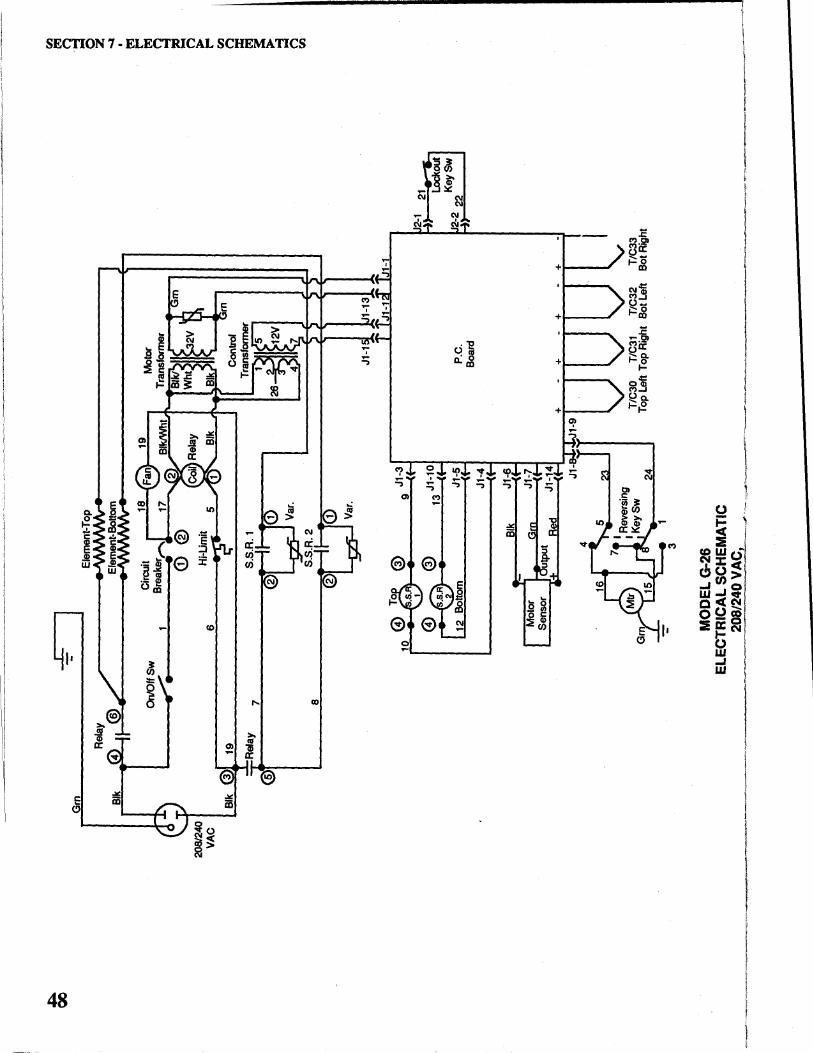
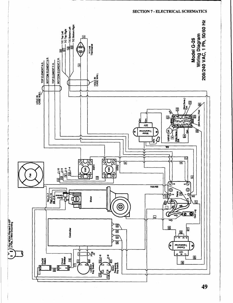
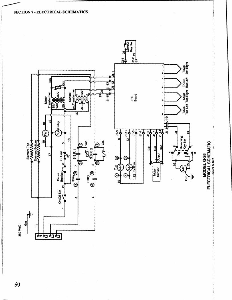
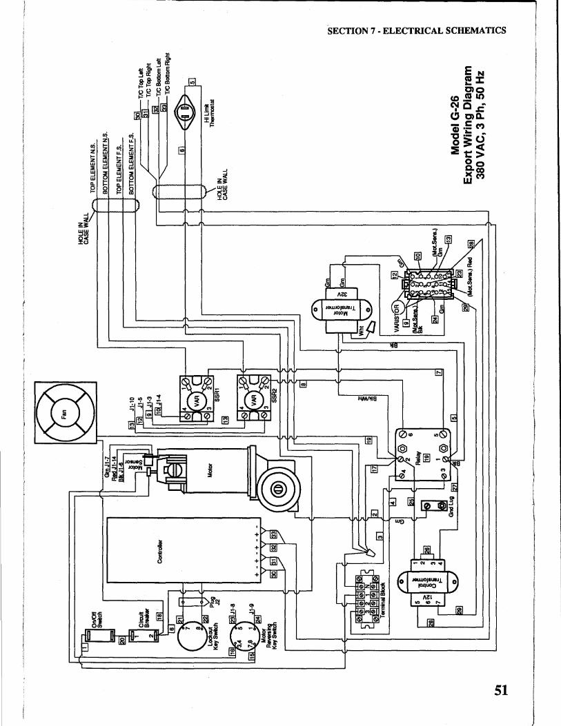
Schematic 208/240VAC, 1 Ph, 50/60Hz ....................................... 48 Wiring Diagram 208/240VAC, 1 Ph, 50/60Hz .............................. .49 Schematic 380VAC, 3 Ph, 50Hz ................................................... 50 Wiring Diagram 380VAC, 3 Ph, 50Hz ........................................... 51
iii
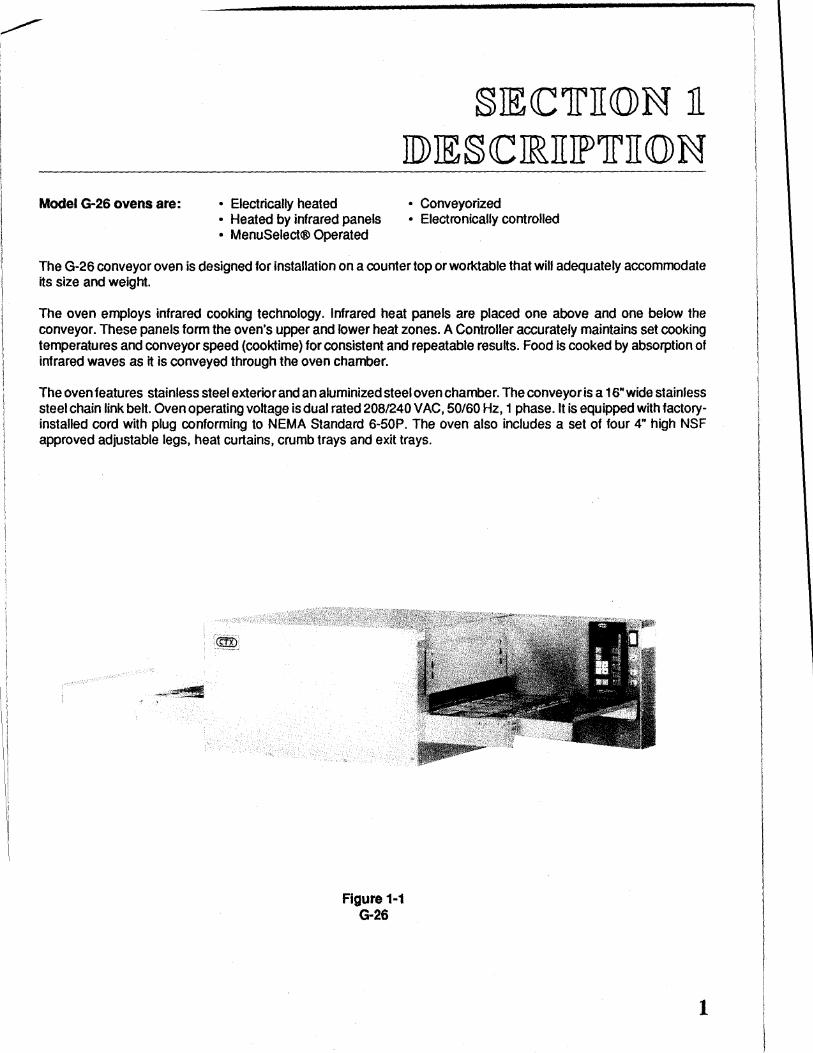
Model G-26 ovens are: • Electrically heated • Heated by infrared panels • MenuSelect® Operated
§JECClrJI(Q)N Jl JD) 1E § CC JRJIJFlrJI (Q) N • Conveyorized • Electronically controlled
The G-26 conveyor oven is designed for installation on a counter top or worktable that will adequately accommodate its size and weight.
The oven employs infrared cooking technology. Infrared heat panels are placed one above and one below the conveyor. These panels form the oven's upper and lower heat zones. A Controller accurately maintains set cooking temperatures and conveyor speed (cooktime) for consistent and repeatable results. Food is cooked by absorption of infrared waves as it is conveyed through the oven chamber.
The oven features stainless steel exterior and an aluminized steel oven chamber. The conveyor is a 16" wide stainless steel chain link belt. Oven operating voltage is dual rated 208/240 VAC, 50/60Hz, 1 phase. It is equipped with factoryinstalled cord with plug conforming to NEMA Standard 6-SOP. The oven also includes a set of four 4" high NSF approved adjustable legs, heat curtains, crumb trays and exit trays.
Figure 1·1 G-26
1
SECTION 1 - DESCRIPfiON
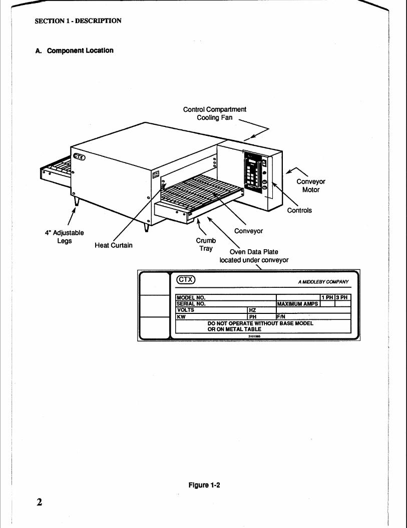
A. Component Location
2
4" Adjustable Legs
Heat Curtain
Control Compartment
CoollngFan "-> ~~..,..
~ c~nveyor Cru~b ~ Tray Oven Data Plate
located under conveyor
' (CTX)
MODEL NO.
Conveyor Motor
A MIDDLEBY COMPANY
11 PHI3PH SERIAL NO. MAXIMUM AMPS I I VOLTS IHZ KW IPH F/N
DO NOT OPERATE WITHOUT BASE MODEL OR ON METAL TABLE
31011515
Figure 1-2
B. Component Function
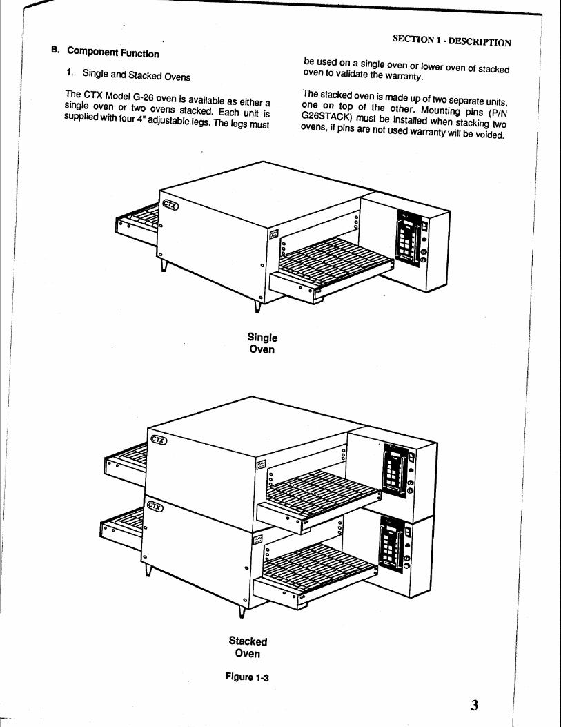
1. Single and Stacked Ovens
The CTX Model G-26 oven is available as either a single oven or two ovens stacked. Each unit is supplied with four 4" adjustable legs. The legs must
Single Oven
Stacked Oven
Figure 1-3
SECTION 1 -DESCRIPTION
be used on a single oven or lower oven of stacked oven to validate the warranty.
The stacked oven is made up of two separate units, one on top of the other. Mounting pins (PIN G26STACK) must be installed when stacking two ovens, it pins are not used warranty will be voided.
3
4
SECTION 1 -DESCRIPTION
2. Cooking Area
The CTX Model G-26 has a 26" (660 mm) long cooking deck (chamber) with a 16" (406 mm) wide conveyor belt.
3. Controller
The Controller controls both the temperature and conveyor belt speed (cook time) of the oven. Cook temperature can be set from 200°F to 950°F (93°C to 509°C) and cook time can be set from 01 :00 minute to 30:00 minutes.
4. Infrared Heating Panels
Patented heating panels are positioned above and below the conveyor belt of each oven deck (cham- · ber). When energized these panels emit infrared long waves. These waves do not heat the air through which they pass. Instead the waves are absorbed by the outer surface of the product transported through the oven on the conveyor belt. Using this application food is placed on the conveyor and the unique properties of the infrared waves cause it to cook from the outside to the center in traditional fashion.
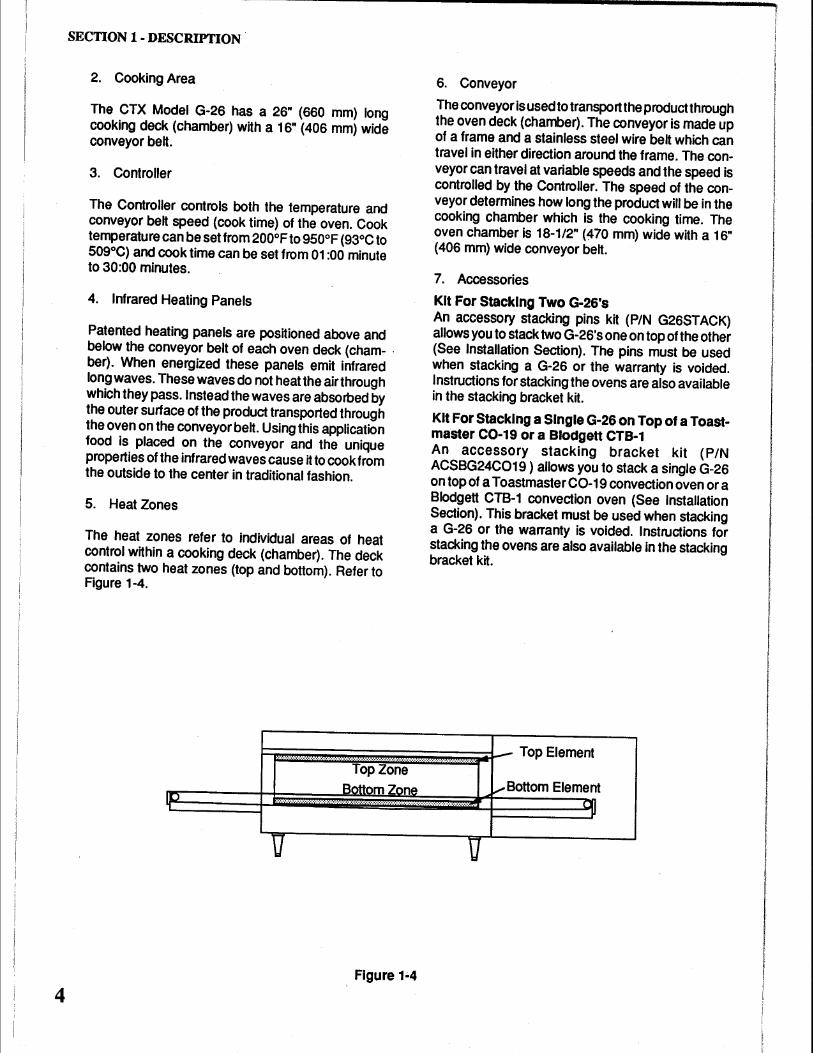
5. Heat Zones
The heat zones refer to individual areas of heat control within a cooking deck (chamber). The deck contains two heat zones (top and bottom). Refer to Figure 1-4.
6. Conveyor
The conveyor is used to transport the product through the oven deck (chamber). The conveyor is made up of a frame and a stainless steel wire belt which can travel in either direction around the frame. The conveyor can travel at variable speeds and the speed is controlled by the Controller. The speed of the conveyor determines how long the product will be in the cooking chamber which is the cooking time. The oven chamber is 18-1/2" (470 mm) wide with a 16" (406 mm) wide conveyor belt.
7. Accessories
Kit For Stacking Two G-26's An accessory stacking pins kit (PIN G26STACK) allows you to stack two G-26's one on top of the other (See Installation Section). The pins must be used when stacking a G-26 or the warranty is voided. Instructions for stacking the ovens are also available in the stacking bracket kit.
Kit For Stacking a Single G-26 on Top of a Toastmaster C0-19 or a Blodgett CTB-1 An accessory stacking bracket kit (PIN ACSBG24C019) allows you to stack a single G-26 on top of a Toastmaster C0-19 convection oven or a Blodgett CTB-1 convection oven (See Installation Section). This bracket must be used when stacking a G-26 or the warranty is voided. Instructions for stacking the ovens are also available in the stacking bracket kit.
Hi .... ;:: .... : .... ;:: ... : .... : .... : ... : .... ij ... ;: ..... ;:: ... ij .... ~· ... i .... i .. ·.ii .... i.· .. ii .... i .... ii ... i .... ii.· .. ~r-- Top Element Top Zone
Ill Bottom Zone
·················.·.·········.·····.·.·····.·.········.·.····.·.···.···.··
u
Figure 1~4
u
~Bottom Element _UI
.JI
SECTION 1 - DESCRIPTION
NOTICE CTX (Manufacturer) reserves the right to change specifications and product design without notice. Such revisions do not entitle the buyer to corresponding changes, improvements,
additions or replacements for previously purchased equipment.
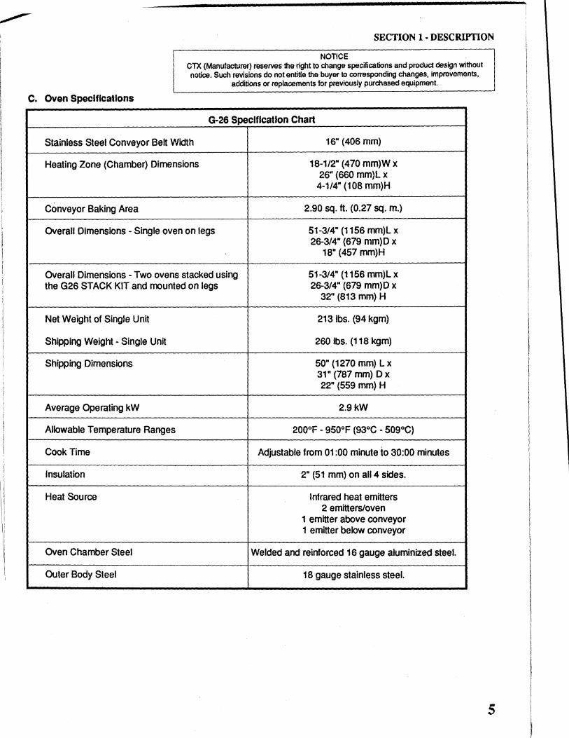
C. Oven Specifications
G-26 Specification Chart
Stainless Steel Conveyor Belt Width 16" (406 mm)
Heating Zone (Chamber) Dimensions 18-1/2" (470 mm)W x 26" (660 mm)L x 4-1/4" (108 mm)H
Conveyor Baking Area 2.90 sq. ft. (0.27 sq. m.)
Overall Dimensions - Single oven on legs 51-3/4" (1156 mm)L x 26-3/4" (679 mm)D x
18" (457 mm)H
Overall Dimensions - Two ovens stacked using 51-3/4" (1156 mm}L x the G26 STACK KIT and mounted on legs 26-3/4" (679 mm)D x
32" (813 mm) H
Net Weight of Single Unit 2131bs. (94 kgm)
Shipping Weight - Single Unit 260 lbs. (118 kgm)
Shipping Dimensions 50" (1270 mm) L x 31" (787 mm) D x 22" (559 mm) H
Average Operating kW 2.9kW
Allowable Temperature Ranges 200°F - 950°F (93°C - 509°C)
Cook Time Adjustable from 01 :00 minute to 30:00 minutes
Insulation 2" (51 mm) on all4 sides.
Heat Source Infrared heat emitters 2 emitters/oven
1 emitter above conveyor 1 emitter below conveyor
Oven Chamber Steel Welded and reinforced 16 gauge aluminized steel.
Outer Body Steel 18 gauge stainless steel.
5
SECTION 1 - DESCRIYI'ION
6
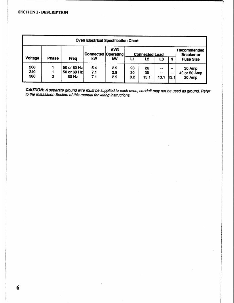
Oven Electrical Specification Chart
AVG Recommended Connected Operating Connected Load Breaker or
Voltage Phase Freq kW kW L1 L2 L3 N Fuse Size
208 1 50 or 60Hz 5.4 2.9 26 26 -- -- 30Amp 240 1 50or60 Hz 7.1 2.9 30 30 -- -- 40 or50Amp 380 3 50 Hz 7.1 2.9 0.2 13.1 13.1 ~3.1 20Amp
CAUTION: A separate ground wire must be supplied to each oven, conduit may not be used as ground. Refer to the Installation Section of this manual for wiring instructions.
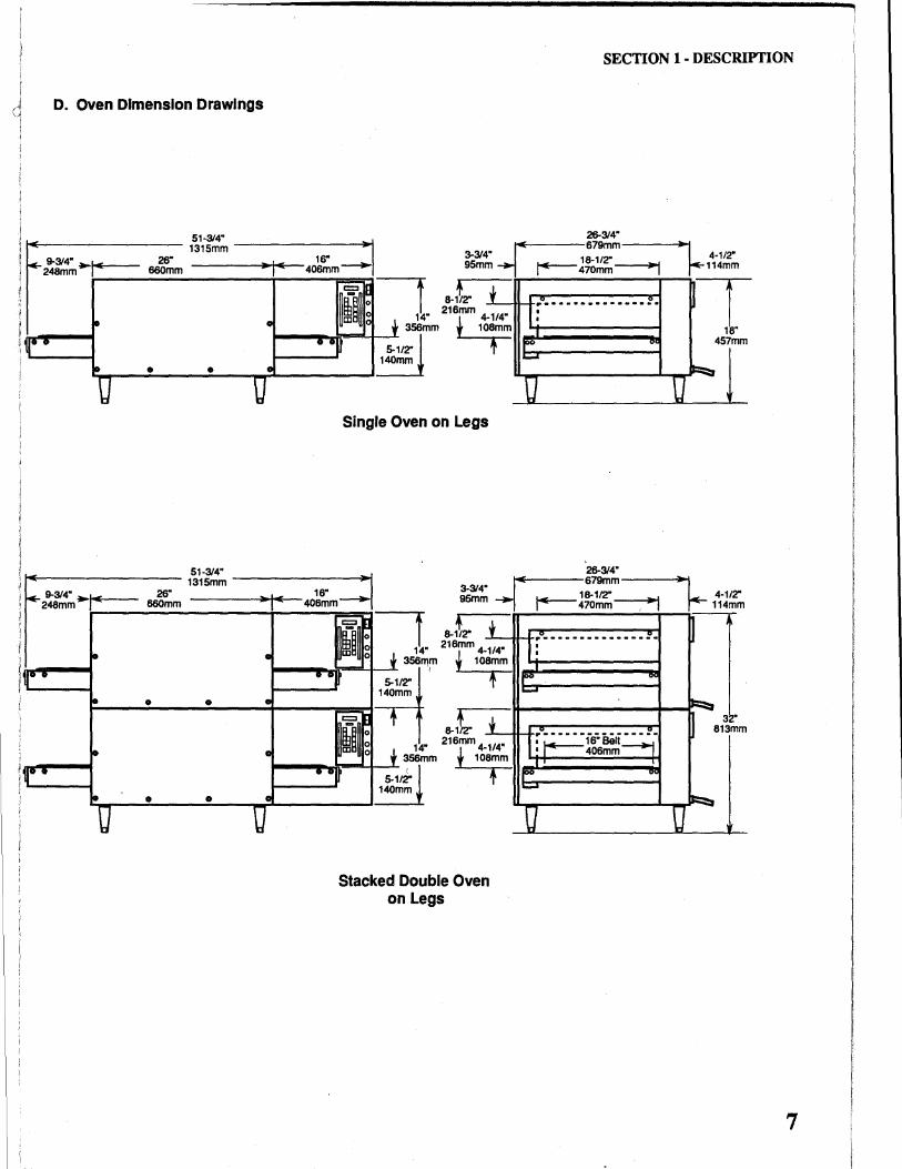
D. Oven Dimension Drawings
26" 660mm
• •
26" 660mm
• 0
• 0
SECTION 1- DESCRIPTION
Single Oven on Legs
26-314" t4----679mm---~
~18-1/'Z'~ 1 · 470mm 1
26-314"
457mm
~i""-.E'-----679mm---~,..~~
3-314" 95mm ~ 18-1/2" ~ 4-1/'Z'
1 · 470mm . 1 114mm
~'Z' f mm 4-1/4" t 108+m
1t 8-216
t mm 4-114"
t 108+m
Stacked Double Oven on Legs
~--·········---~-I: 1
r" "" ..... ~ -J
3 •
······---··----~-813mm
1• ~~6-aei:---J • 406mm
F "" 1 ......
~ -a u
7
SECTION 1 · DESCRIPI10N
8
26-314" 1~\"f~~ -------~,..~~ ~._---679mm---~,...~~
L- 9-314" .. ,,IE--- 26" ----~·-+, .... ,,____ 16" - .~ :s~~ .....,___ 18-1/2" ~ 4-1/2" r--248mm .,_ 660mm - ... 406mm--- 1 470mm 1 114mm
~~--------------.r---~~-,u=n~· ~t,. i. ' ln ........... --~. • • • •• 9 ~
~~; .~" r~~·· m
t2" j_ 6mm4-1/4"
~·.
• •
~+--------_.
• .. 5-1/2": J 1---..... 140mm •
29_-: 16" 741mm
6" 152mm
t
f 108+m
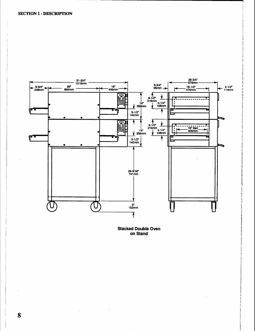
Stacked Double Oven on Stand
.v ..... --.... --. !'. ~ j: II"" "' 1-
b...
~-~------·····-····
1• t+---?6" Bel~ ' 406mm
IE "' 1-
b. -
a [
I I I I
I !
I I I
I t I
I
A. Inspect for Shipping Damage
All shipping containers should be examined for damage before and during unloading. This equipment was carefully inspected and packaged at the factory. The freight carrier has assumed responsibility for its safe transit and delivery. If equipment is received in damaged condition, either apparent or concealed, a claim must be made with the delivering carrier.
1. Apparent Damage or Loss - If damage or loss is apparent it must be noted on the freight bill or express receipt at the time of delivery, and it must be signed by the carrier's agent (driver). If this is not done, the carrier may refuse the claim. The carrier will supply the necessary claim forms.
2. Concealed Damage or Loss - If damage or loss is NOT apparent until after equipment is uncrated, a request for inspection of concealed damage must be made with carrier within 15 days. The carrier will make an inspection and will supply necessary claim forms. Be certain to retain all contents plus external and internal packaging/crating materials for inspection.
§lEClrii([))N ~ JIN§lr AILILA lrJI([))N
B. Placement of Oven
Some very important considerations must be made when choosing the place where the oven is to operate.
1. This oven is conveyorized and operates continuously.lt should be placed so it fits into the "flow" of the operation.
2. Drafts entering the oven chambers can cause inconsistent cooking results. Check the area surrounding the oven and eliminate sources of drafts such as open windows or door's and .fans or other appliances that cause air circulation.
3. Oven should be positioned so hot air from another piece of equipment cannot enter oven cooling fan air intake on the control compartment. Serious problems could occur.
NOTE: To validate a new oven(s) warranty a factory certified installer must verify that Steps C thru K
have been performed correctly.
9
SECTION 2- INSTALLATION
c. Unpacking Oven
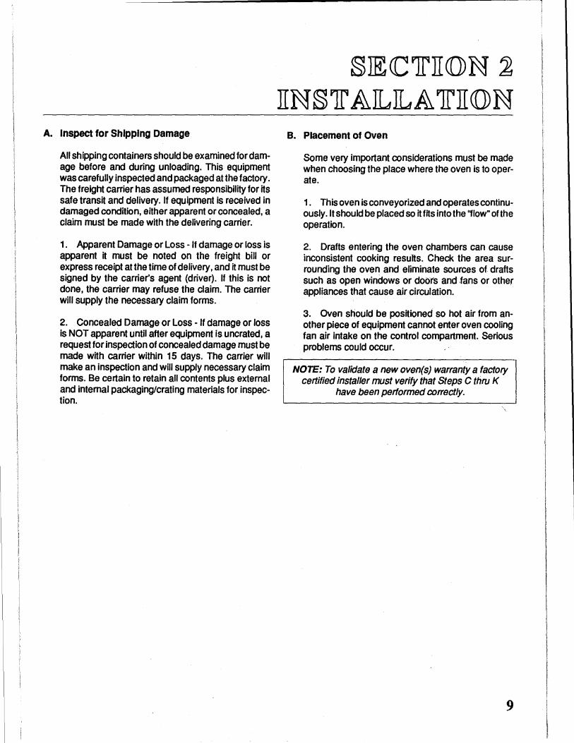
The oven components should be moved as close as possible to final location before being assembled/ stacked. The oven setting on its bottom, requires door openings wider than 26-3/4" (679 mm).
Open carton and remove it from around oven, then remove the empty carton from the area. Directions for removing the wooden skid are on the following page.
Short Exit Tray
Standoffs
Attached to the conveyor belt is a box containing one (1) short exit tray, one (1) long exit tray, two (2) pivoting heat curtains, four (4) adjustable 4" legs, four(4) standoffs and two (2) sets of keys. (See Figure 2-1). Check to make sure you received the correct quantity of parts.
Pivoting Heat Curtains
Two Sets Of Keys
Long Exit Tray
4" Adjustable Legs NSF
Figure 2-1
10
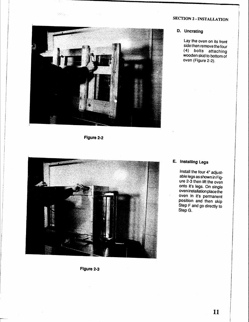
Figure 2·2
Figure 2·3
SECTION 2 ·INSTALLATION
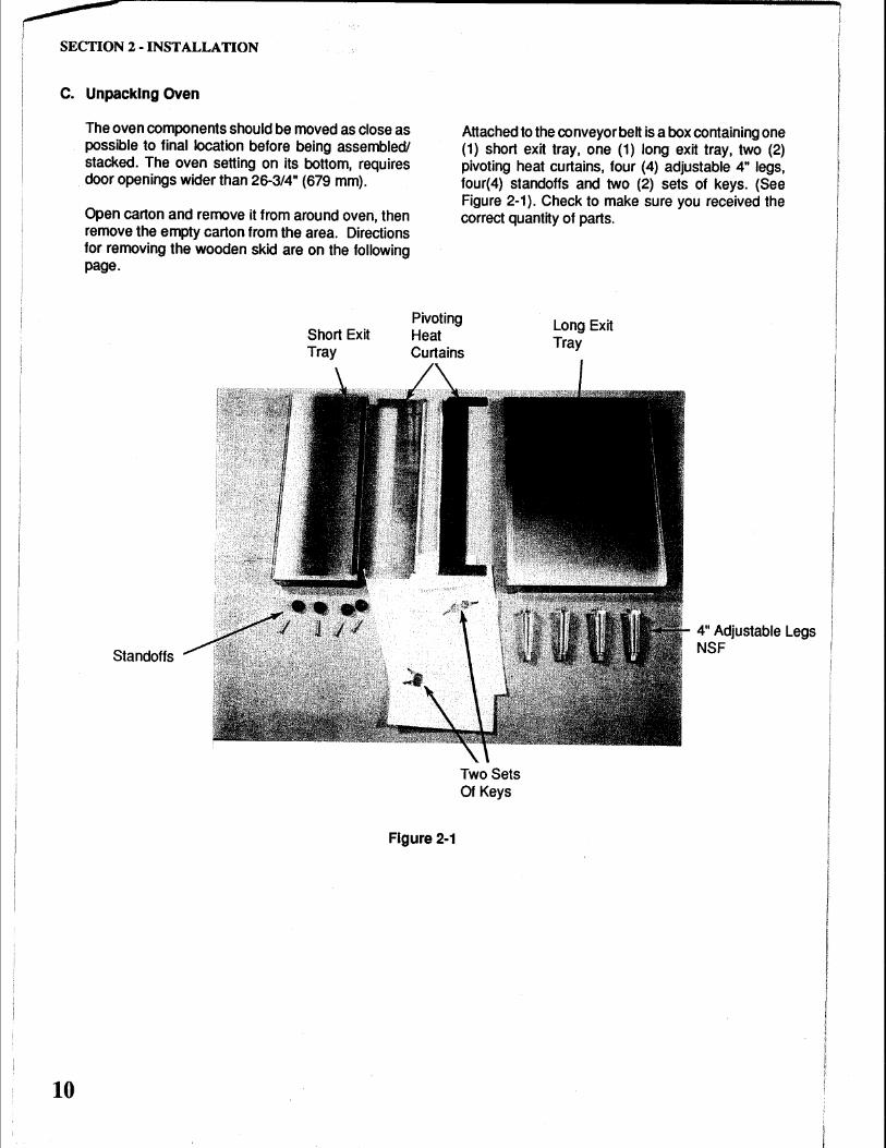
D. Uncratlng
Lay the oven on its front side then remove the four (4) bolts attaching wooden skid to bottom of oven (Figure 2-2).
E. Installing Legs
Install the four 4" adjustable legs as shown in Figure 2-3 then lift the oven onto it's legs. On single oven installation place the oven in it's permanent position and then skip Step F and go directly to Step G.
11
SECTION 2 -INSTALLATION
F. Stacking and Mounting Two Ovens
NOTE: A stacking pins kit(Kit # G26STACK) is required when stacking two ovens
12
1. Move the lower oven (oven with legs installed) to it's permanent position. Remove the two plug buttons, one located in each rear top corner hole of lower oven.
2. Unpack the upper oven. Locate the two (2) stacking pins in the kit. Install the two pins into the two bottom rear threaded holes of the upper oven. These are the holes normally used for the rear legs.
3. Using four people lift the upper oven on top of the lower oven. Align the stacking pins as shown in Figure 2-4 with the holes in the top of the lower oven and lower the oven into place.
Stacking Pins In Upper Oven
Figure 2-4
Holes In Lower Oven
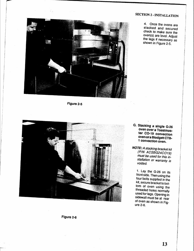
Figure 2·5
Figure 2·6
SECTION 2 • INSTALLATION
4. Once the ovens are stacked and secured check to make sure the oven(s) are level. Adjust the legs if necessary as shown in Figure 2-5.
G. Stacking a single G-26 oven over a Toastmaster C0-19 convection oven or a BlOdgett CTB-1 convection oven.
NOTE: A stacking bracket kit (PIN ACSBG24C019) must be used for this installation or warranty is voided.
1. Lay the G-26 on its front side. Then using the four bolts supplied in the kit, secure bracket to bottom of oven using the threaded holes normally used for legs. Opening in sidewall must be at rear of oven as shown in Figure 2-6.
13
SECTION 2 - INSTALLATION
14
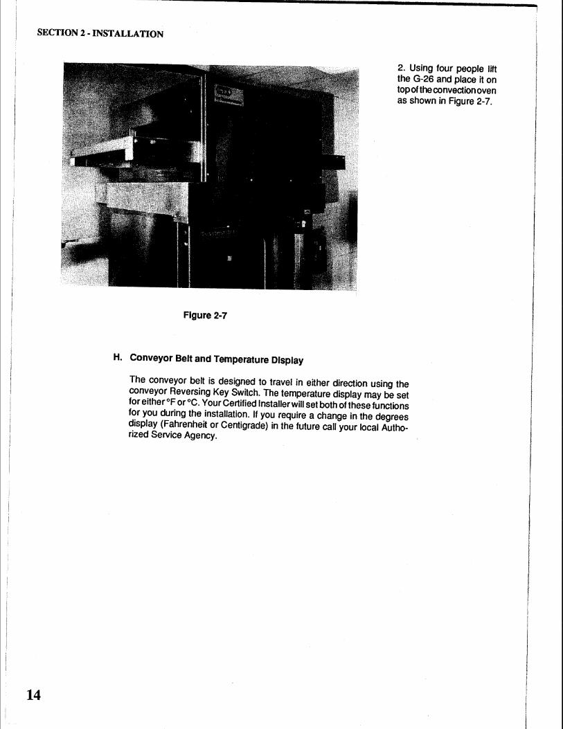
Figure 2-7
H. Conveyor Belt and Temperature Display
2. Using four people lift the G-26 and place it on top of the convection oven as shown in Figure 2-7.
The conveyor belt is designed to travel in either direction using the conveyor Reversing Key Switch. The temperature display may be set for either °F or °C. Your Certified Installer will set both of these functions for you during the installation. If you require a change in the degrees display (Fahrenheit or Centigrade) in the future call your local Authorized Service Agency.
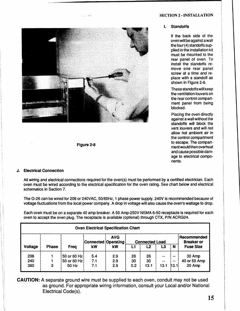
Figure 2·8
J. Electrical Connection
SECTION 2 ·INSTALLATION
I. Standoffs
If the back side of the oven will be against a wall thefour(4} standoffs supplied in the installation kit must be mounted to the rear panel of oven. To install the standoffs remove one rear panel screw at a time and replace with a standoff as shown in Figure 2-8.
These standoffs will keep the ventilation louvers on the rear control compartment panel from being blocked.
Placing the oven directly against a wall without the standoffs will block the vent louvers and will not allow hot ambient air in the control compartment to escape. The compartment would then overheat and cause possible damage to electrical components.
All wiring and electrical connections required for the oven(s) must be performed by a certified electrician. Each oven must be wired according to the electrical specification for the oven rating. See chart below and electrical schematics in Section 7.
The G-26 can be wired for 208 or 240VAC, 50/60Hz, 1 phase power supply. 240V is recommended because of voltage fluctuations from the local power compa.ny. A drop in voltage will also cause the oven's wattage to drop.
Each oven must be on a separate 40 amp breaker. A 50 Amp-250V NEMA 6-50 receptacle is required for each oven to accept the oven plug. The receptacle is available (optional) through CTX, PIN ACRG24.
Oven Electrical Specification Chart
AVG Recommended Connected Operating Connected Load Breaker or
Voltage Phase Freq kW kW L1 L2 L3 N Fuse Size
208 1 50 or 60Hz 5.4 2.9 26 26 -- -- 30Amp 240 1 50 or 60Hz 7.1 2.9 30 30 -- -- 40 or 50 Amp 380 3 50 Hz 7.1 2.9 0.2 13.1 13.1 13.1 20Amp
CAUTION: A separate ground wire must be supplied to each oven, conduit may not be used as ground. For appropriate wiring information, consult your Local and/or National Electrical Code(s).
15
SECTION 2 ·INSTALLATION
16
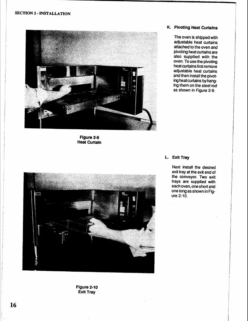
Figure 2·9 Heat Curtain
Figure 2·10 Exit Tray
K. Pivoting Heat Curtains
The oven is shipped with adjustable heat curtains attached to the oven and pivoting heat curtains are also supplied with the oven. To use the pivoting heat curtains first remove adjustable heat curtains and then install the pivoting heat curtains by hanging them on the steel rod as shown in Figure 2-9.
L. Exit Tray
Next install the desired exit tray at the exit end of the conveyor. Two exit trays are supplied with each oven, one short and one long as shown in Figure 2-10.
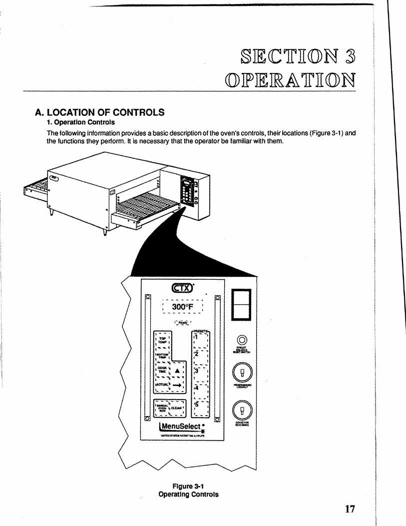
A. LOCATION OF CONTROLS 1. Operation Controls
§JE<Clrii«J)N ~ ({)) JF JE llR A lr II({)) N
The following information provides a basic description of the oven's controls, their locations (Figure 3-1) and the functions they perform. It is necessary that the operator be familiar with them.
PRESETS ;;- -1
I
... - -· •2-' I I
I_--' ;3-- I
I I - -. 14- -1
LMenuSelect • liE
lJNR'E.DaTA'JEI:PA1'ENTtGI,117_m
Figure 3-1 Operating Controls
17
SECTION 3 • OPERATION
B. MenuSelect® CONTROL OPERATION & PROGRAMMING
18
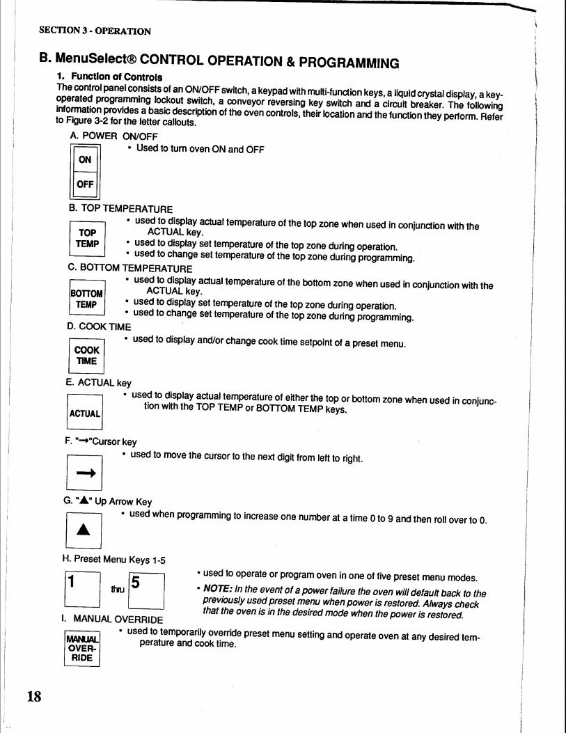
1. Function of Controls The control panel cOnsists of an ON/OFF switch, a keypad with multi-function keys, a liquid crystal display, a keyoperated programming lockout switch, a conveyor reversing key switch and a circuit breaker. The following information provides a basic description of the oven controls, their location and the function they perform. Refer to Figure 3-2 for the letter callouts.
A. POWER ON/OFF ~ • Used to turn oven ON and OFF
B B. TOPTEMPERATURE
• used to display actual temperature of the top zone when used in conjunction with the ACTUAL key.
• used to display set temperature of the top zone during operation. • used to change set temperature of the top zone during programming.
C. BOTIOM TEMPERATURE
• used to display actual temperature of the bottom zone when used in conjunction with the BOITOM ACTUAL key.
TEMP • used to display set temperature of the top zone during operation. • used to change set temperature of the top zone during programming.
D. COOK TIME
~ ~
• used to display and/or change cook time setpoint of a preset menu.
E. ACTUAL key
• used to display actual temperature of either the top or bottom zone when used in conjunction with the TOP TEMP or BOTIOM TEMP keys.
F. " ..... "Cursor key
• used to move the cursor to the next digit from left to right.
G. ".6." Up Arrow Key
• used when programming to increase one number at a time 0 to 9 and then roll over to 0.
H. Preset Menu Keys 1-5
• used to operate or program oven in one of five preset menu modes.
I. MANUAL OVERRIDE
• NOTE: In the event of a power failure the oven will default back to the previously used preset menu when power is restored. Always check that the oven is in the desired mode when the power is restored.
MANJAL. OVERRIDE
• used to temporarily override preset menu setting and operate oven at any desired temperature and cook time.
SECTION 3 • OPERATION
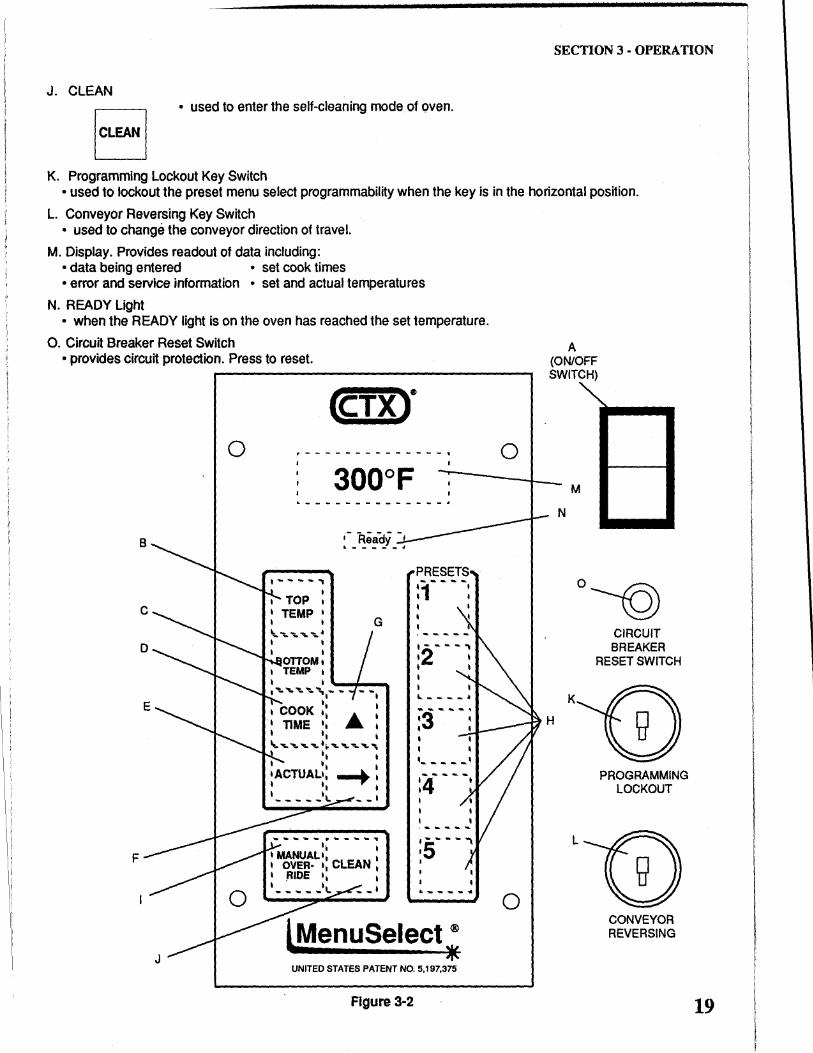
J. CLEAN
[CLEAN I • used to enter the self-cleaning mode of oven.
K. Programming Lockout Key Switch • used to lockout the preset menu select programmability when the key is in the horizontal position.
L. Conveyor Reversing Key Switch • used to change the conveyor direction of travel.
M. Display. Provides readout of data including: • data being entered • set cook times ·error and service information • set and actual temperatures
N. READY Light • when the READY light is on the oven has reached the set temperature.
0. Circuit Breaker Reset Switch • provides circuit protection. Press to reset.
0
,-Ready-~-----"
G
F
lMenuSelect; UNITED STATES PATENT NO. 5,197,375
Figure 3·2
0
0
A (ON/OFF SWITCH)
N
H
M
0-©
K
L
CIRCUIT BREAKER
RESET SWITCH
PROGRAMMING LOCKOUT
CONVEYOR REVERSING
19
SECTION 3 - OPERATION
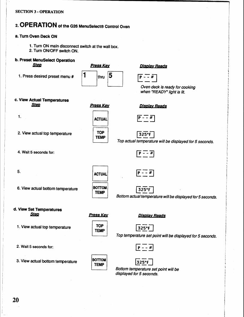
2. OPERATION of the G26 MenuSelect® Control Oven
a. Turn Oven Deck ON
1. Turn ON main disconnect switch at the wall box. 2. Turn ON/OFF switch ON.
b. Preset MenuSelect Operation mJ1JJ. PressKev Display Reads
1. Press desired preset menu# Dthru D Oven deck is ready for cooking when "READY" light is lit.
c. VIew Actual Temperatures mJ1JJ. PressKev
1.
2. View actual top temperature
4. Wait 5 seconds for:
5.
6. View actual bottom temperature
d. VIew Set Temperatures mm
1. View actual top temperature
2. Wait 5 seconds for:
3. View actual bottom temperature
20
[ACTUALI
§
B BOlT OM TEMP
fressKev
~ ~
BOlT OM TEMP
Display Beads
~25°~ Top actual temperature will be displayed tor 5 seconds.
~25°~ Bottom actual temperature will be displayed for 5 seconds.
Display Reads
11:25°U
Top temperature set point will be displayed for 5 seconds.
(!25°F] Bottom temperature set point will be displayed for 5 seconds.
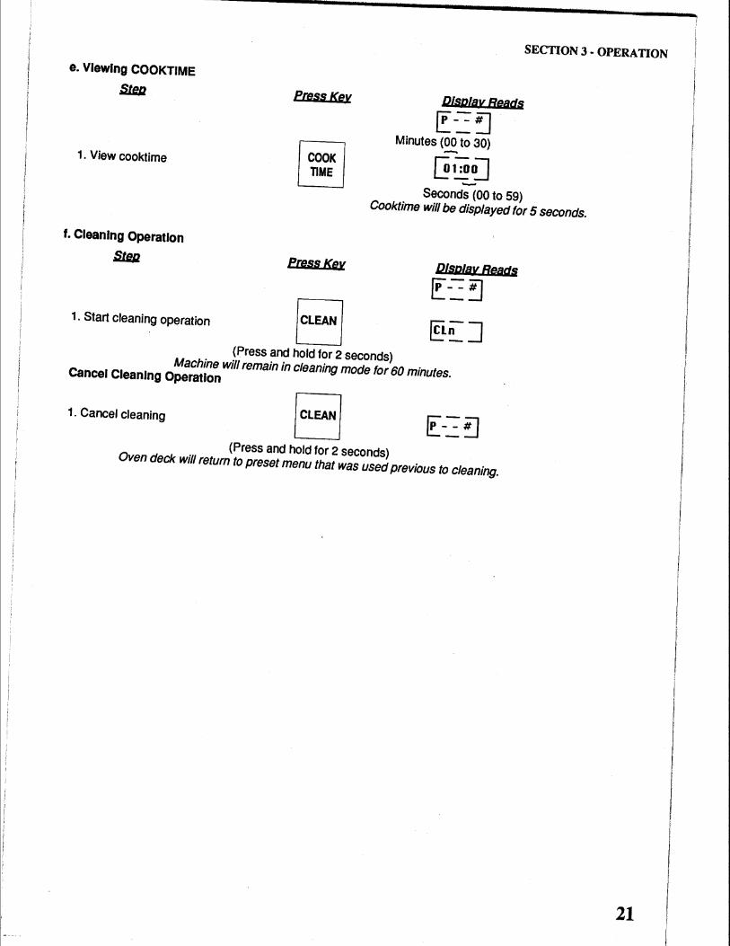
e. VIewing COOKTIME
S1Jlll
1. View cooktime
Press Key
~ ~
SECTION 3 - OPERATION
Dfsplav Reads
~--~ Minutes (00 to 30) -
~l:oaQ -Seconds (00 to 59) Cooktime will be displayed for 5 seconds.
f. Cleaning Operation
S1Jlll Press Key Dtsp/av Reads
~--~
1. Start cleaning operation I CLEAN I § n J (Press and hold for 2 seconds)
Machine will remain in cleaning mode for 60 minutes. Cancel Cleaning Operation
1. Cancel cleaning I CLEAN I (Press and hold for 2 seconds)
Oven deck will return to preset menu that was used previous to cleaning.
21
SECTION 3 • OPERATION
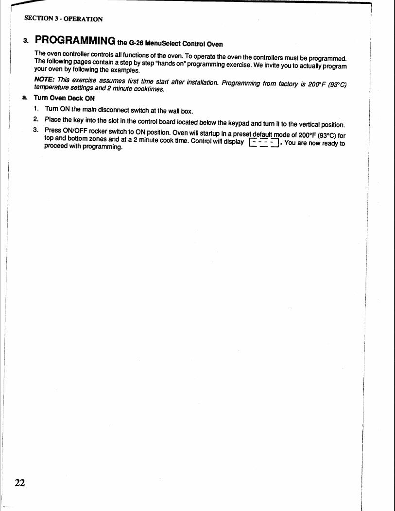
3. PROGRAMMING the G·26 MenuSelect Control Oven
The oven controller controls all functions of the oven. To operate the oven the controllers must be programmed. The following pages contain a step by step "hands on" programming exercise. We invite you to actually program your oven by following the examples.
NOTE: This exercise assumes first time start after installation. Programming from factory is 20CPF (9SOC) temperature settings and 2 minute cooktimes.
a. Turn Oven Deck ON
22
1. Tum ON the main disconnect switch at the wall box.
2. Place the key into the slot in the control board located below the keypad and turn it to the vertical position.
3. Press ON/OFF rocker switch to ON position. Oven will startup in a preset default mode of 200°F (93°C) for top and bottom zones and at a 2 minute cook time. Control will display [: --= ::J. You are now ready to proceed with programming. -
SECTION 3 - OPERATION
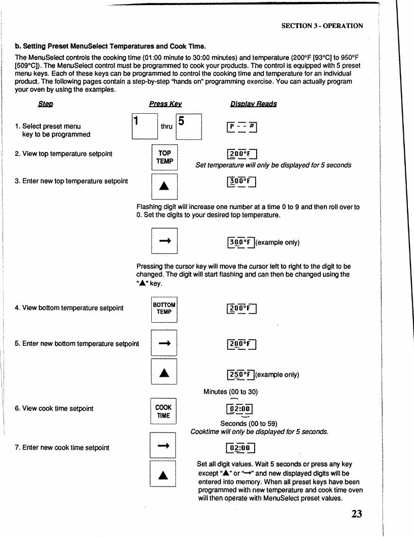
b. Setting Preset MenuSelect Temperatures and Cook Time.
The MenuSelect controls the cooking time (01 :00 minute to 30:00 minutes) and temperature (200°F [93°C] to 950°F [509°C]). The MenuSelect control must be programmed to cook your products. The control is equipped with 5 preset menu keys. Each of these keys can be programmed to control the cooking time and temperature for an individual product. The following pages contain a step-by-step "hands on" programming exercise. You can actually program your oven by using the examples.
1. Select preset menu key to be programmed
2. View top temperature setpoint
3. Enter new top temperature setpoint
4. View bottom temperature setpoint
eressKey DiSPfay Reacts
Set temperature will only be displayed for 5 seconds
Flashing digit will increase one number at a time 0 to 9 and then roll over to 0. Set the digits to your desired top temperature.
@:~oo~(example only)
Pressing the cursor key will move the cursor left to right to the digit to be changed. The digit will start flashing and can then be changed using the "A" key.
BOTIOM TEMP
5. Enter new bottom temperature setpoint
6. View cook time setpoint
7. Enter new cook time setpoint
~ ~
~~oo!](example only)
Minutes (00 to 30)
(].2:0~
Seconds (00 to 59) Cooktime will only be displayed for 5 seconds.
Set all digit values. Wait 5 seconds or press any key except "A" or"-+" and new displayed digits will be entered into memory. When all preset keys have been programmed with new temperature and cook time oven will then operate with MenuSelect preset values.
23
SECTION 3 - OPERATION
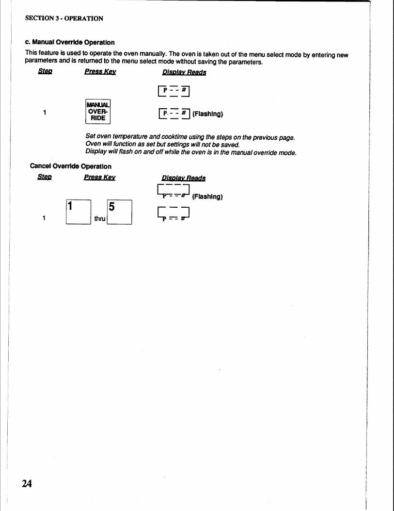
c. Manual Override Operation
This feature is us~d to operate the oven manually. The oven is taken out of the menu select mode by entering new parameters and is returned to the menu select mode without saving the parameters.
1
PressKev
MAMlAI.. OVERRIDE
Display Reads
[!. - -~ (Flashing)
Set oven temperature and cooktime using the steps on the previous page. Oven will function as set but settings will not be saved. Display will flash on and off while the oven is in the manual oveffide mode.
Cancel Override Operation
1
24
Press Key Display Beads
~ ~) (Flashing)
SECTION 3 - OPERATION
C. Cooking in a CTX Oven
Before you begin to cook with your new oven you must understand the differences between cooking in it and cooking in more conventional ovens. You will produce better results if you understand the technology and follow the "rules".
1. Infrared Cooking Technology
The technology of infrared cooking used in the CTX Gemini series ovens was first introduced by CTX in 1969. Each oven is fitted with patented infrared emitting heat panels (heating elements). These elements form the top and bottom surfaces of the oven chamber. The G-26 has two elements, one above and one below the conveyor belt.
These elements emit infrared "longwaves" which are absorbed by almost all matter in varying degrees. Absorption of these waves by an object causes molecular agitation which causes friction which generates heat. In this instance the object is food and the heat generated is used to cook the food. Infrared waves penetrate the outer surfaces of the food where they are absorbed by virtually all ingredients plus the container in which the food is placed. As a result, food cooks from the outside toward the center in very traditional fashion.
Infrared waves, unlike conventional heat sources, do not heat the air through which they pass, nor do they create any air currents in the oven chamber to dry out the food product. If there is no food product in the oven the infrared waves are absorbed by the heating elements located opposite. These unique properties translate into less food waste, a more moist product and excellent energy efficiency.
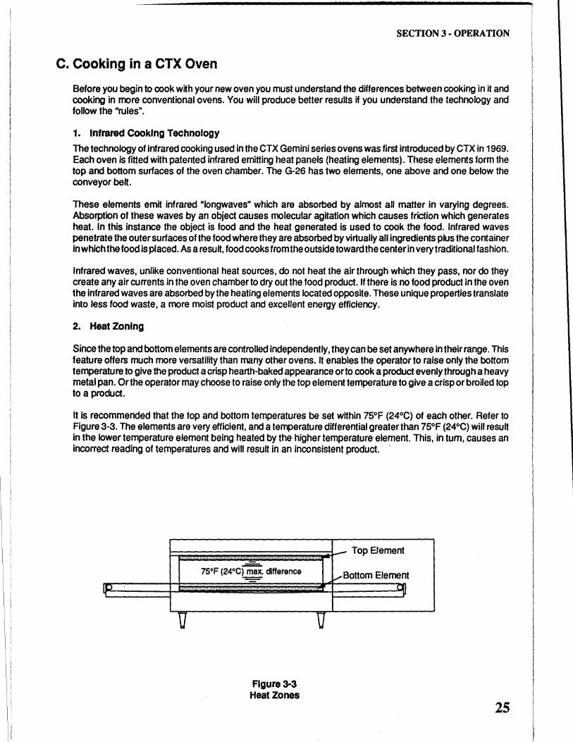
2. Heat Zoning
Since the top and bottom elements are controlled independently, they can be set anywhere in their range. This feature offers much more versatility than many other ovens. It enables the operator to raise only the bottom temperature to give the product a crisp hearth-baked appearance or to cook a product evenly through a heavy metal pan. Or the operator may choose to raise only the top element temperature to give a crisp or broiled top to a product.
It is recommended that the top and bottom temperatures be set within 75°F (24°C) of each other. Refer to Figure 3-3. The elements are very efficient, and a temperature differential greater than 75°F (24°C) will result in the lower temperature element being heated by the higher temperature element. This, in turn, causes an incorrect reading of temperatures and will result in an inconsistent product. ·
I~
p=j:.:: ..... :: .... z ... : .... z .... : ... :: .... : ... : .... : ... ~ .... ;; ... :: .... :: ... : .... :: ... :. iiiiii~tf--- Top Element
u
Figure 3-3 Heat Zones
u
/Bottom Element ::JI -~~
25
SECTION 3 - OPERATION
26
4.
3. General "Rules of Thumb"
Cooking in a CTX infrared conveyor oven is different than cooking in any other type of oven including microwave ovens. Because of these differences there are some "rules" that must be considered.
a. Continuous "Flow" Operation
CTX ovens perform best in a continuous type of operating environment. They are not well suited to a batch type operation. Greatest efficiency is attained when as many steps as possible in the operation are put into a continuous "flow" pattern.
b. Pans
The type of vessel used to hold the food has a bearing on cooking time and consistency of results.
1. Pans with a dull black finish absorb maximum infrared heat. Product cooks faster in dull black pans than in shiny silver ones.
2. Heavier (thicker gauge) pans cook more evenly. They heat slower but hold their heat longer.
Lighter (thinner gauge) pans transfer heat faster but less evenly. They also cool faster.
c. Product
Best results are obtained when product entering the oven is consistent.
1. Food portions entering the oven should all be approximately the same temperature. When food portions entering the oven vary in temperature, the temperature of those portions coming out of the oven, though cooked, will also vary.
2. Product size should be the same. If product is 1/2" thick one time and 3/4" thick the next, cooking results will be different.
3. Product loading density also affects results. If portion size and pan size are the same, two portions per pan will cook differently than ten portions per pan.
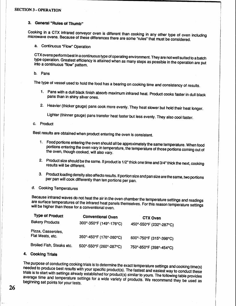
d. Cooking Temperatures
Because infrared waves do not heat the air in the oven chamber the temperature settings and readings are surface temperatures of the infrared heat panels themselves. For this reason temperature settings will be higher than those for a conventional oven.
Type of Product Conventional Oven CTXOven Bakery Products 300°-350°F (149°-176°C) 450°-550°F (232°-287°C)
Pizza, Casseroles, Flat Meats, etc. 350°-450°F (176°-260°C) 600°-750°F (315°-398°C)
Broiled Fish, Steaks etc. 500°-550°F (260°-287°C) 750°-850°F (398°-454°C)
Cooking Trials
The purpose of conducting cooking trials is to determine the exact temperature settings and cooking time(s) needed to produce best results with your specific product(s). The fastest and easiest way to conduct these trials is to start with settings already established for product(s) similar to yours. The following table provides average time and temperature settings for a wide variety of products. We recommend they be used as beginning set points for your tests.
SECTION 3 • OPERATION
Testing can be completed easier and faster and with Jess confusion if you keep accurate records of each test. To assist you we have included a sample product test form that you can copy.
Choose your first product for test and look it up in the table on the following pages. Now program the oven with the temperatures and cooktimes shown.
NOTE: If you are starting the oven from "cold" please allow 45 minutes heat up time. The elements cycle after approximately 15 minutes, however, additional time is needed for the oven chamber(s) to become stabilized and evenly saturated with heat.
Begin your first trial run. Examine the finished product and evaluate it based on the following guidelines.
RESULTS
Outside too dark or burned Outside too light or not cooked Inside Overdone or dried out Inside Underdone or raw
SOLUTION
Reduce Temperatures Increase Temperatures Shorten Cooking Time Lengthen Cooking Time
NOTE: Sometimes an increase in temperature may require a corresponding decrease in cooking time. Conversely a decrease in temperature may require a corresponding increase in cooking time.
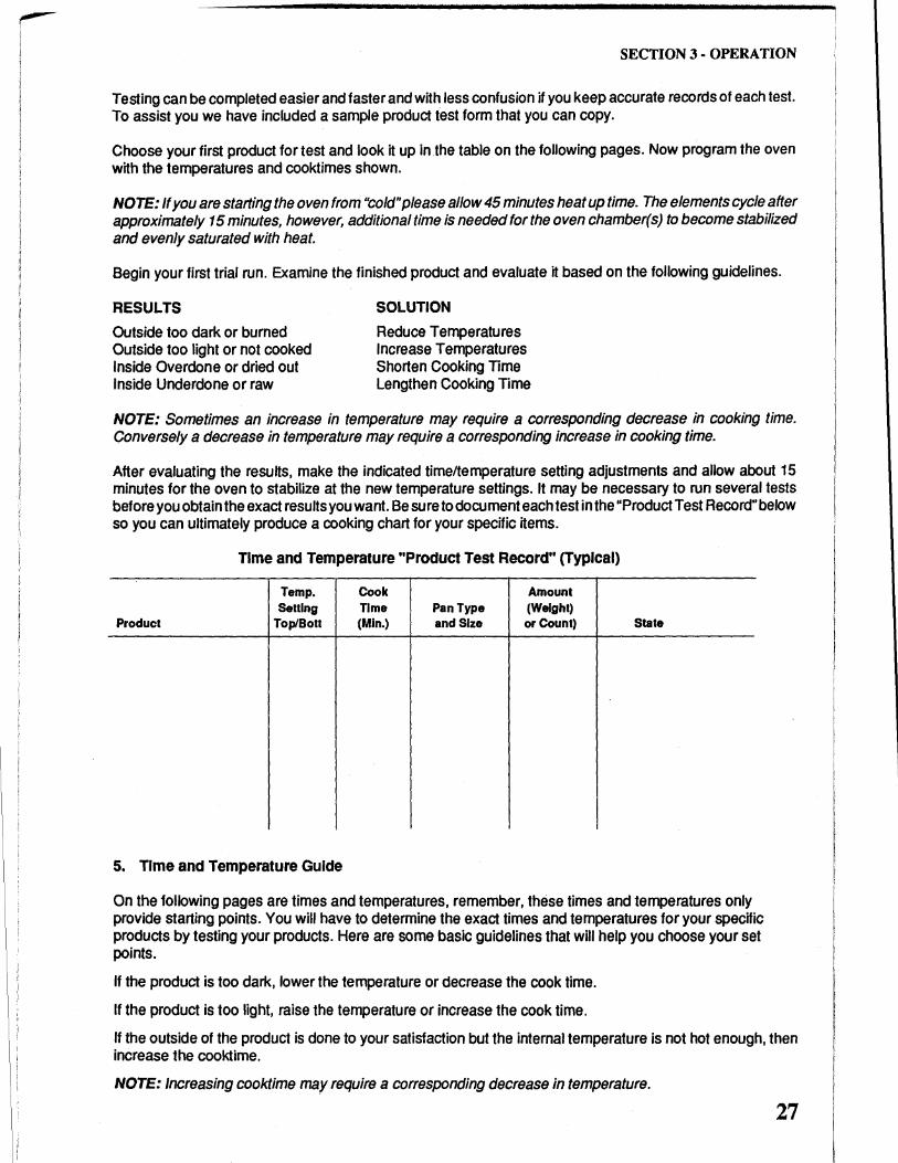
After evaluating the results, make the indicated time/temperature setting adjustments and allow about 15 minutes for the oven to stabilize at the new temperature settings. It may be necessary to run several tests before you obtain the exact results you want. Be sure to document each test in the "Product Test Record" below so you can ultimately produce a cooking chart for your specific items.
Time and Temperature "Product Test Record" (Typical)
Temp. Cook Amount Setting Time Pan Type (Weight)
Product Top/Bolt (Min.) and Size or Count) State
5. Time and Temperature Guide
On the following pages are times and temperatures, remember, these times and temperatures only provide starting points. You will have to determine the exact times and temperatures for your specific products by testing your products. Here are some basic guidelines that will help you choose your set points.
If the product is too dark, lower the temperature or decrease the cook time.
If the product is too light, raise the temperature or increase the cook time.
If the outside of the product is done to your satisfaction but the internal temperature is not hot enough, then increase the cooktime.
NOTE: Increasing cooktime may require a corresponding decrease in temperature.
27
SECTION 3 • OPERATION
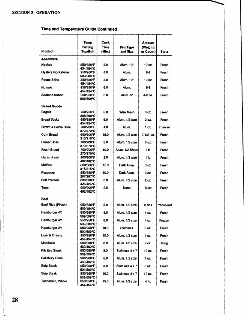
Time and Temperature Guide Continued
Temp Cook Amount Senlng Time Pan Type (Weight)
Product Top/Boll (Min.) and Size or Count) State
Appetizers
Nachos 850/850°F 3.0 Alum.10" 10oz. Fresh 454/454°C
Oysters Rockefeller 950/950°F 4.0 Alum. 6-8 Fresh 509/509°C
Potato Skins 850/850°F 3.0 Alum. 10" 10oz. Fresh 454/454°C
Rumaki 850/850°F 6.0 Alum. 6-8 Fresh 454/454°C
Seafood Kabob 9501950°F 6.0 Alum. 6" 4-6oz. Fresh 509/509°C
BakedGooda
Bagels 750n50°F 8.0 Wire Mesh 3oz. Fresh 3981398°C
Bread Sticks 850/850°F 6.0 Alum. 112 size 2oz. Fresh 454/454°C
Brown & Serve Rolls 700/700°F 4.0 Alum. 1 oz. Thawed 370/370°C
Com Bread 600/600°F 15.0 Alum. 112 size 2-1121bs. Fresh 3151315°C
Dinner Rolls 700noooF 8.0 Alum. 112 size 3oz. Fresh 370137000
Fresh Bread 700/700°F 10.0 Alum. 112 Sheet 11b. Fresh 3701370°C
Garlic Bread 90019000F 2.0 Alum. 112 size 11b. Fresh 4821482°C
Muffins 600/600°F 15.0 Dark Alum. 3oz. Fresh 3151315°C
Popovers 550/550°F 30.0 Dark Alum. 3oz. Fresh 2871287°C
Soft Pretzels 800/800°F 8.0 Alum. 1/2 size 2oz. Fresh 426/426°C
Toast 900/900°F 2.0 None Slice Fresh 4821482°C
Beef
Beef Ribs (Finish) 950/850°F 8.0 Alum. 1/2 size 8 ribs Precooked 509/454°C
Hamburger 4/1 9501950°F 4.0 Alum. 112 size 4oz. Fresh 509/509°C
Hamburger 4/1 9501950°F 6.6 Alum. 112 size 4 oz. Frozen 509/509°C
Hamburger 211 9501950°F 10.0 Stainless 8oz. Fresh 509/509°C
Liver & Onions 850/850°F 10.0 Alum. 1/2 size 4oz. Fresh 454/454°C
Meatballs 900/900°F 8.0 Alum. 112 size 2oz. Refrig. 4821482°C
Rib Eye Steak 9501950°F 8.0 Stainless 4 x 7 10oz. Fresh 509/509°C
SaHsbury Steak 900/900°F 6.0 Alum. 1.2 size 4oz. Fresh 4821482°C
Strip Steak 9501950°F 8.0 Stainless 4 x 7 8oz. Fresh 509/509°C
Strip Steak 950/9500F 10.0 Stainless 4 x 7 12oz. Fresh 509/509°C
Tenderloin, Whole 850/850°F 15.0 Alum. 1/2 size 41b. Fresh 454/454°C
28
SECTION 3 - OPERATION
Temp. Cook Amount Setting Time Pan Type (Weight)
Product Top/Bott (Min.) and Size or Count) State
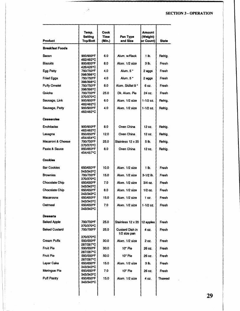
Breakfast Foods
Bacon 900/900"F 6.0 Alum. w/Rack 11b. Retrig. 482/482°C
Biscuits 800/800°F 8.0 Alum. 1/2 size 31b. Fresh 426/426°C
Egg Patty 750/750°F 4.0 Alum. 5" 2eggs Fresh 3981398°C
Fried Eggs 750/750"F 4.0 Alum. 5 • 2eggs Fresh 3981398°C
Puffy Omelet 750/750°F 8.0 Alum. Skillet 9 • 6oz. Fresh 398/398°C
Quiche 700/700°F 25.0 Dk. Alum. Pie 24oz. Fresh 370/370°C
Sausage, Link 9001900°F 6.0 Alum. 1/2 size 1-1/2oz. Refrig. 482/482°C
Sausage, Patty 900/900°F 4.0 Alum. 1/2 size 1-1/2 oz. Refrig. 482/482°C
casseroles
Enchiladas 900/900"F 8.0 Oven China 12oz. Refrig. 482/482°C
Lasagna 850/850°F 12.0 Oven China 12oz. Refrig. 454/454°C
Macaroni & Cheese 700/700°F 25.0 Stainless 12 x 20 Sib. Refrig. 370/370°C
Pasta & Sauce 850/850°F 8.0 Oven China 12oz. Refrig. 454/457°C
Cookies
Bar Cookies 650/650°F 10.0 Alum. 1/2 size 11b. Fresh 343/343°C
Brownies 7001700°F 15.0 Alum. 1/2 size 3-1/21b. Fresh 370/370°C
Chocolate Chip 650/650°F 7.0 Alum. 1/2 size 314 oz. Fresh 343/343°C
Chocolate Chip 650/650°F 8.0 Alum. 1/2 size 1/2 oz. Fresh 343/343°C
Macaroons 650/6500F 15.0 Alum. 1/2 size 1 oz. Fresh 343/343°C
Oatmeal 650/650°F 7.0 Alum. 1/2 size 1-1/2 oz. Fresh 343/343°C
Desserts
Baked Apple 700/700°F 25.0 Stainless 12 x 20 12apples Fresh 370/370°C
Baked Custard 700/700"F 25.0 Custard Dish in 4oz. Fresh 1/2 size pan
370/3700C Cream Puffs 550/550"F 30.0 Alum. 1/2 size 2oz. Fresh
2871287°C Fruit Pie 550/550°F 30.0 10" Pie 26oz. Fresh
287/28~C Fruit Pie 550/550°F 50.0 10" Pie 26oz. Fresh
287/287°C Layer Cake 650/650°F 15.0 Alum. 1/2 size 31b. Fresh
343/343°C Meringue Pie 650/650°F 7.0 10" Pie 26oz. Fresh
343/343°C Puff Pastry 650/650°F 15.0 Alum. 1/2 size 4oz. Thawed
343/343°C
29

SECTION 3 • OPERATION
Temp. Cook Amount Setting Time Pan Type (Weight)
Product Top/Bolt (Min.) and Size or Count) State
Fish & Seafood
Filet of Sole 950/950"F 6.0 Stainless 4 x 7 6oz. Fresh 509/509°C
Lobster Tail 950/950°F 8.0 Stainless 4 x 7 8oz. Fresh 509/509°C wlwater
Sea Scallops 950/950°F 6.0 Stainless 4 x 7 8 oz. Fresh 509/509°C
Shrimp Scampi 950/9500F 6.0 Stainless 4 x 7 8oz. Fresh 509/509°C
Snow Crab 950/950°F 6.0 Stainless 9 x 11 8oz. Fresh 509/509°C
Stuffed Flounder 950/950°F 8.0 Stainless 4 x 7 8 oz. Fresh 509/509°C
White Fish Fillet 950/950°F 8.0 Strainless 4 x 7 8oz. Fresh 509/509°C
Whole Trout 950/950°F 8.0 Stainless 9 x 11 9oz. Fresh 509/509°C
Pizza
Deep Dish 750/7500F 10.0 Black Deep Pan Fresh 3981398°C
Calzone 675/675°F 8.0 Pizza Screen or Fresh 3571357°C Black Sheet Pan
Stuffed 650/650°F 20.0 Black Deep Pan Fresh 3431343°C
Thick Crust 7751775°F 6.5 Black Pizza Pan Fresh 4121412°C
Thin Crust 800/800°F 5.5 Pizza Screen Fresh 426/426°C
Thin Crust 650/650°F 9.0 Pizza Screen Frozen 343134300
Thin Crust 800/800°F 5.0 Pizza Screen Pre-bake 426/426°C
Pork
Breaded Chop 800/800°F 8.0 Alum. 112 size 4 oz. Precooked 426/426°C
Pork Chops 800/800°F 15.0 Alum. 112 size 4 oz. Fresh 426/426°C
Pork Ribs (Finish) 950/950°F 8.0 Alum. 112 size Slab Precooked 509/509°C
Poultry
Chicken Cordon Bleu 800/800°F 15.0 Alum. 1/2 size 12 pes. Fresh 426/426°C
Chicken Pieces 800/800°F 18.0 Alum. 112 size 12 pes. Fresh 426/426°C
Half Chicken 800/800°F 20.0 Alum. 112 size 1-1141b. Fresh 426/426°C
Whole Chicken 800/800°F 25.0 Alum. 112 size 2-1121b. Fresh
30
SECTION 3 - OPERATION
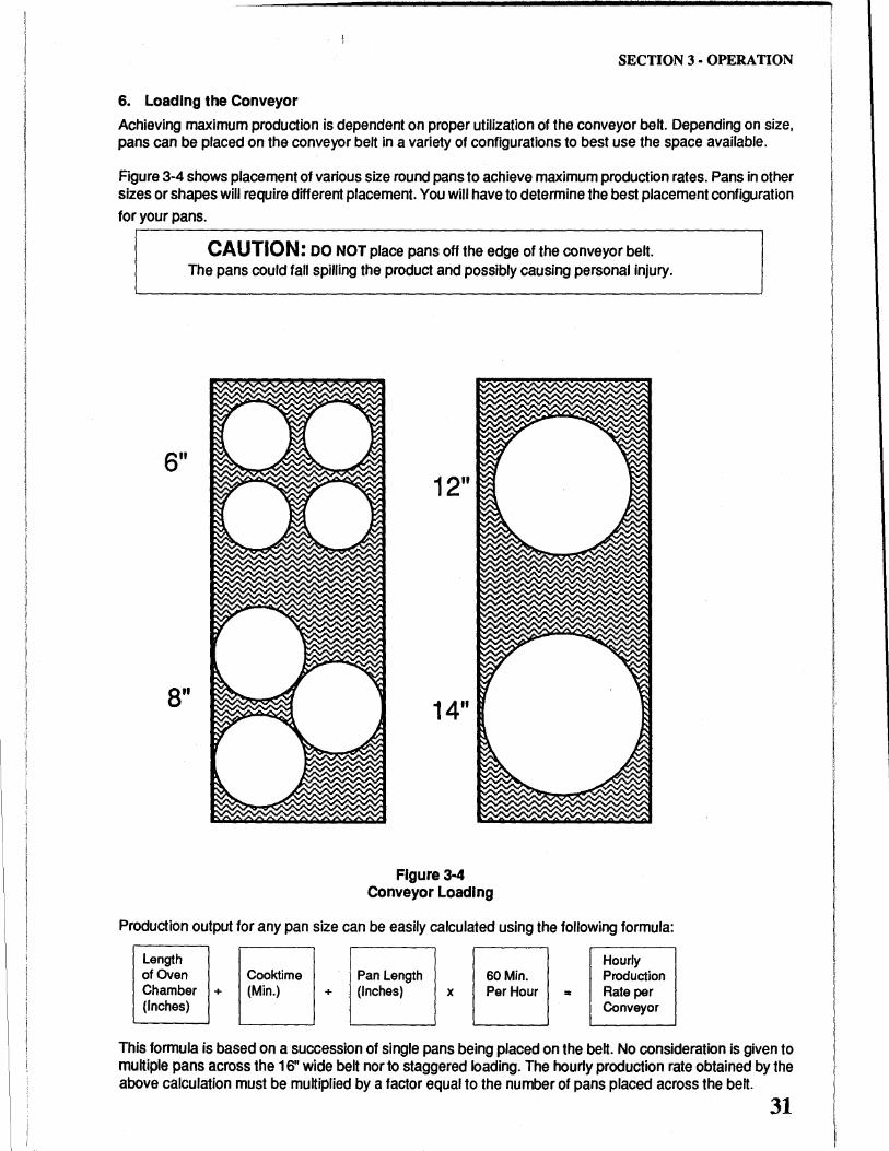
6. Loading the Conveyor
Achieving maximum production is dependent on proper utilization of the conveyor belt. Depending on size, pans can be placed on the conveyor belt in a variety of configurations to best use the space available.
Figure 3-4 shows placement of various size round pans to achieve maximum production rates. Pans in other sizes or shapes will require different placement. You will have to determine the best placement configuration for your pans.
CAUTION: DO NOT place pans off the edge of the conveyor belt. The pans could fall spilling the product and possibly causing personal injury.
6"
8"
12"
14"
Figure 3·4 Conveyor Loading
Production output for any pan size can be easily calculated using the following formula:
Length of Oven Chamber + (Inches)
Cooktime (Min.) +
Pan Length (Inches) x
60Min. Per Hour =
Hourly Production Rate per Conveyor
This formula is based on a succession of single pans being placed on the belt. No consideration is given to multiple pans across the 16" wide belt nor to staggered loading. The hourly production rate obtained by the above calculation must be multiplied by a factor equal to the number of pans placed across the belt.
31
SECTION 3 - OPERATION
32
Cooktlme
*5" *&"
1 min. 312 260
2min. 156 130
3min. 104 87
4min. 78 65
5min. 62 52
6min. 52 43
7min. 45 37
Smin. 39 33
9min. 35 29
10min. 31 26
11 min. 28 24
12min. 26 22
13 min. 24 20
14min. 22 18.5
15min. 21 17
16min. 19.5 16
17min. 18 15
18 min. 17 14.5
19 min. 16.5 14
20min. 15.5 13
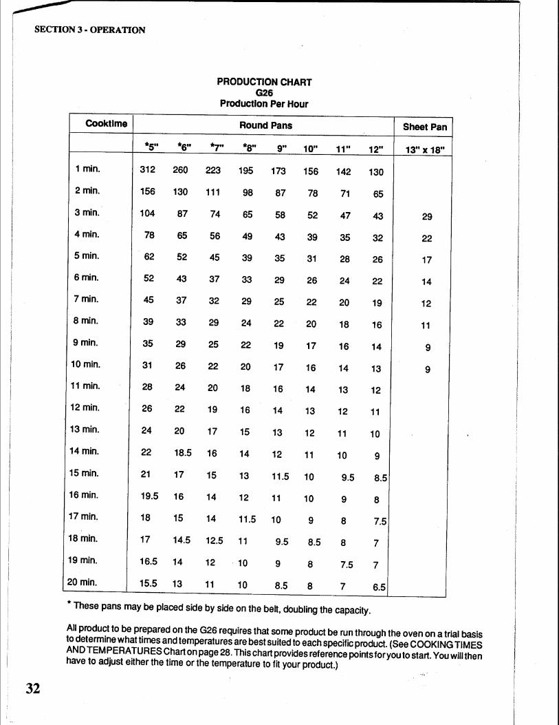
PRODUCTION CHART G26
Production Per Hour
Round Pans
.., .. *8" 9" 10"
223 195 173 156
111 98 87 78
74 65 58 52
56 49 43 39
45 39 35 31
37 33 29 26
32 29 25 22
29 24 22 20
25 22 19 17
22 20 17 16
20 18 16 14
19 16 14 13
17 15 13 12
16 14 12 11
15 13 11.5 10
14 12 11 10
14 11.5 10 9
12.5 11 9.5 8.5
12 10 9 8
11 10 8.5 8
11" 12"
142 130
71 65
47 43
35 32
28 26
24 22
20 19
18 16
16 14
14 13
13 12
12 11
11 10
10 9
9.5 8.5
9 8
8 7.5
8 7
7.5 7
7 6.5
* These pans may be placed side by side on the belt, doubling the capacity.
Sheet Pan
13" X 18"
29
22
17
14
12
11
9
9
All product to be prepared on the G26 requires that some product be run through the oven on a trial basis to determine what times and temperatures are best suited to each specific product. (See COOKING TIMES AND TEMPERATURES Chart on page 28. This chart provides reference points for you to start. You will then have to adjust either the time or the temperature to fit your product.)
§JECCJrJI(Q)N ~ CCJLJEANIIN CG ~
IMIAJINlrJEN AN CCJE
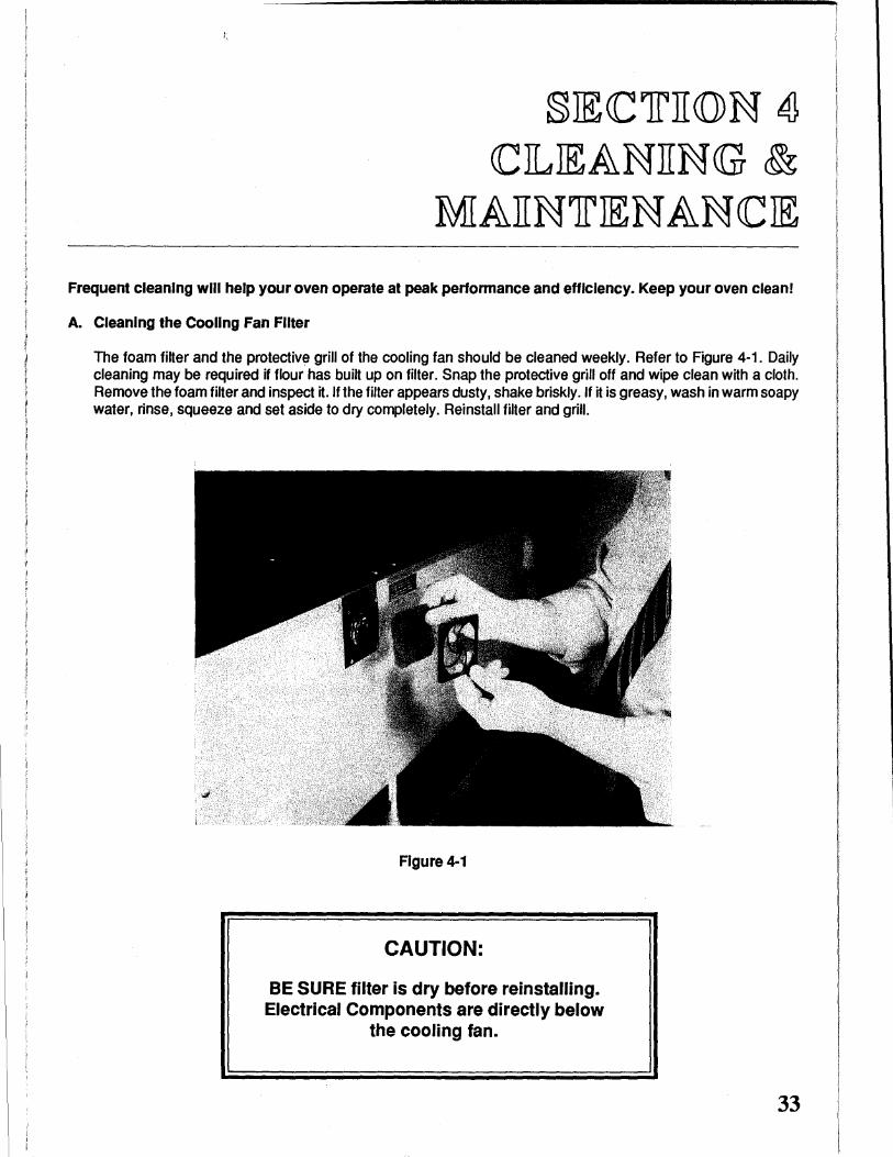
Frequent cleaning will help your oven operate at peak performance and efficiency. Keep your oven clean!
A. Cleaning the Cooling Fan Filter
The foam fiHer and the protective grill of the cooling fan should be cleaned weekly. Refer to Figure 4-1. Daily cleaning may be required if flour has buiH up on filter. Snap the protective grill off and wipe clean with a cloth. Remove the foam filter and inspect it.lfthe filter appears dusty, shake briskly.lf it is greasy, wash in warm soapy water, rinse, squeeze and set aside to dry completely. Reinstall filter and grill.
Figure 4-1
CAUTION:
BE SURE filter is dry before reinstalling. Electrical Components are directly below
the cooling fan.
33
34
SECTION 4- CLEANING & MAINTENANCE
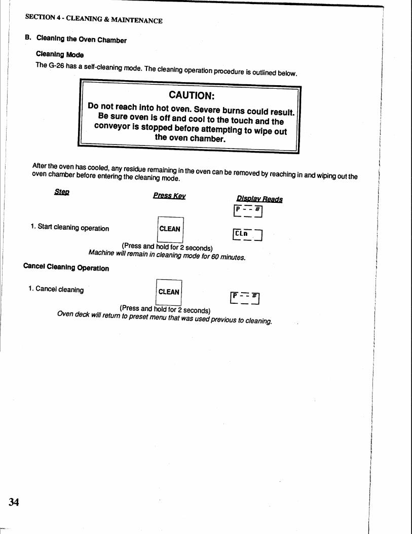
B. Cleaning the Oven Chamber
Cleaning Mode
The G-26 has a self-cleaning mode. The cleaning operation procedure is outlined below.
CAUTION: Do not reach Into hot oven. Severe burns could result.
Be sure oven Is off and cool to the touch and the conveyor is stopped before attempting to wipe out
the oven chamber.
After the oven has cooled, any residue remaining in the oven can be removed by reaching in and wiping out the oven chamber before entering the cleaning mode.
PrusKeJt Display Reacts
r~~ 1. Start cleaning operation /CLEAN I ~Ln J
(Press and hold for 2 seconds) Machine will remain in cleaning mode for 60 minutes.
Cancel Cleaning Operation
1. cancel cleaning I CLEAN I f!: ~ ~ (Press and hold for 2 seconds)
Oven deck will return to preset menu that was used previous to cleaning.
I I I
I I
I I
I I r
I
! l I ' i
I
SECTION 4 - CLEANING & MAINTENANCE
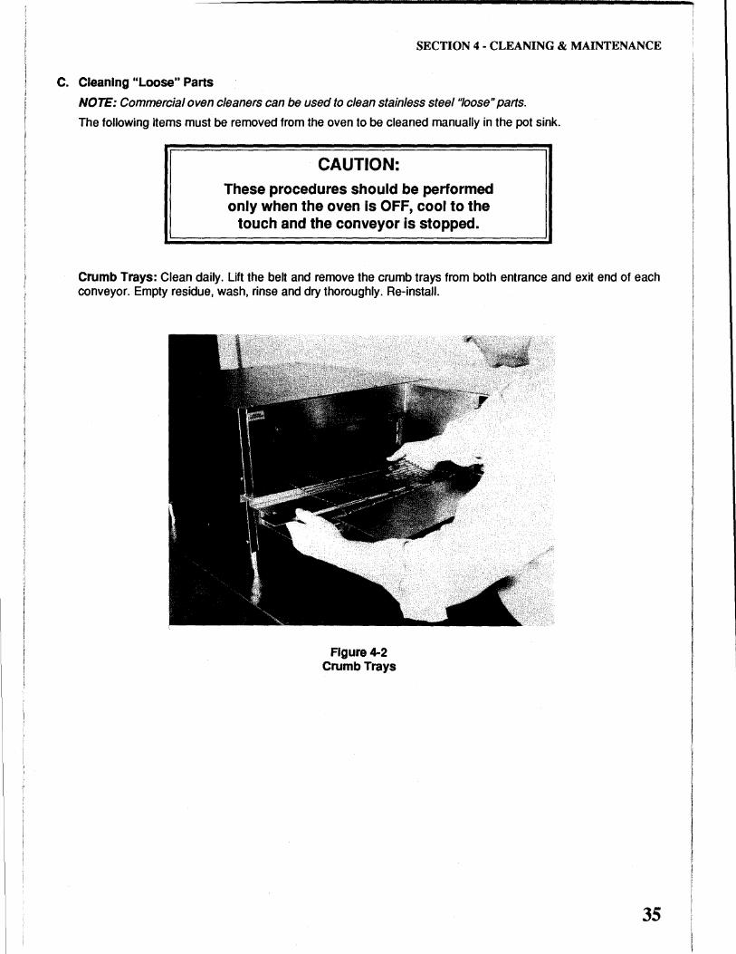
C. Cleaning "Loose" Parts
NOTE: Commercial oven cleaners can be used to clean stainless steel"loose" parts.
The following items must be removed from the oven to be cleaned manually in the pot sink.
CAUTION: These procedures should be performed only when the oven is OFF, cool to the
touch and the conveyor is stopped.
Crumb Trays: Clean daily. Lift the belt and remove the crumb trays from both entrance and exit end of each conveyor. Empty residue, wash, rinse and dry thoroughly. Re-install.
Figure 4-2 Crumb Trays
35
36
SECTION 4 ·CLEANING & MAINTENANCE
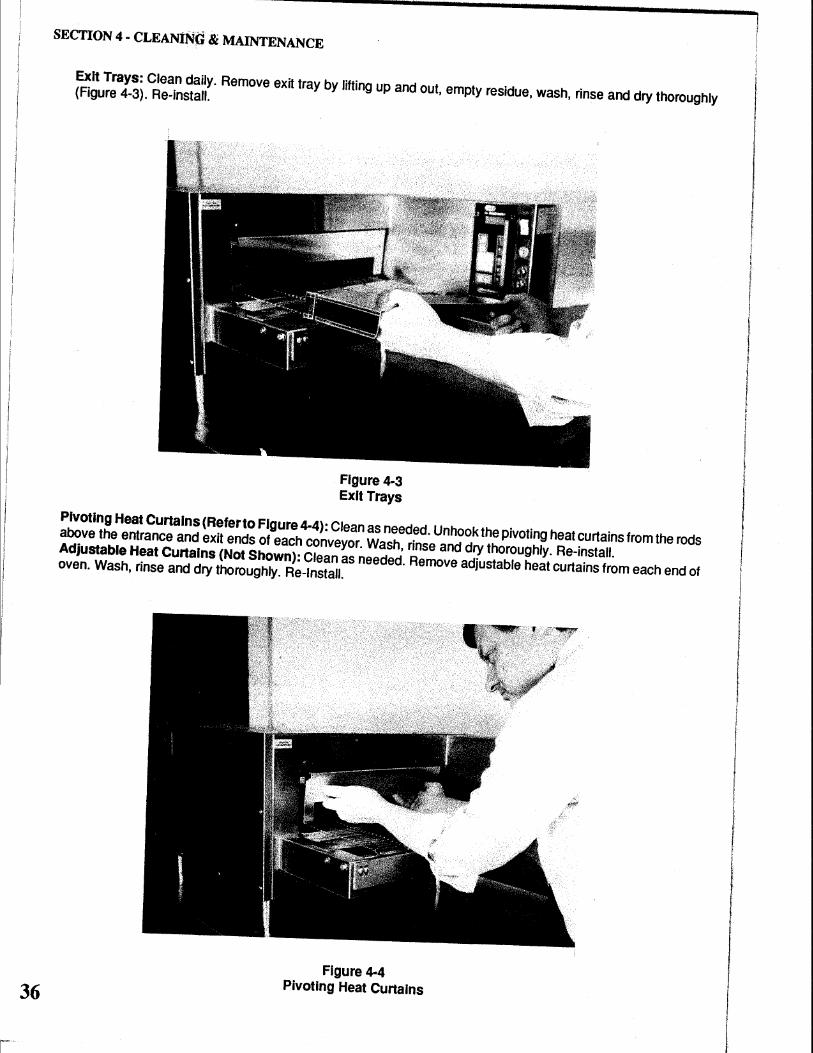
Exit Trays: Clean daily. Remove exit tray by lifting up and out, empty residue, wash, rinse and dry thoroughly (Figure 4-3). Re-install.
Figure 4·3 Exit Trays
Pivoting Heat Cunalns (Refer to Figure 4-4): Clean as needed. Unhook the pivoting heat curtains from the rods above the entrance and exit ends of each conveyor. Wash, rinse and dry thoroughly. Re-install. Adjustable Heat Cunalns (Not Shown): Clean as needed. Remove adjustable heat curtains from each end of oven. Wash, rinse and dry thoroughly. Re-Install.
Figure 4·4 Pivoting Heat Cunains
SECTION 4 - CLEANING & MAINTENANCE
D. Cleaning the Exterior
CAUTION: Disconnect the oven's power supply cord from its receptacle
before you start to clean the oven.
Clean the outside of the unit using a damp cloth or stainless steel cleaner. Do not clean the control panel with an abrasive cleanser. Use only a damp cloth. Be very careful when cleaning the unit not to allow water to enter the unit through any of the openings in the control panel box. Liquid in the control panel area could cause damage to the controls or could cause electrical shorts in the unit which could shock someone. Do not allow water or water droplets to enter into the: a) fan filter, b) louvers on the side of the oven, c) area behind the control panel, or d) operating controls.
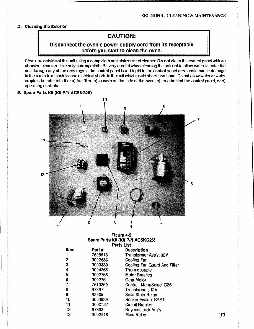
E. Spare Parts Kit (Kit P/N ACSKG26)
10
13
1 4
Figure 4-5 Spare Parts Kit (Kit P/N ACSKG26)
Item 1 2 3 4 5 6 7 8 9 10 11 12 13
Part# 7608516 3002686 3000330 3004265 3002755 3002751 7610250 97397 82905 3003839 300C:'27 97393 3002918
Parts List Description Transformer Ass'y, 32V Cooling Fan Cooling Fan Guard And Filter Thermocouple Motor Brushes Gear Motor Control, MenuSelect G26 Transformer, 12V Solid State Relay Rocker Switch, SPST Circuit Breaker Bayonet Lock Ass'y Main Relay
7
37
SECTION 4 ·CLEANING & MAINTENANCE
NOTES:
38
I I
I I I I j
Plug in No oven?
§m<eJrJI(Q)N ~ 1r m (Q) 1UlB3IL m § mr (Q) (Q) TJIN G
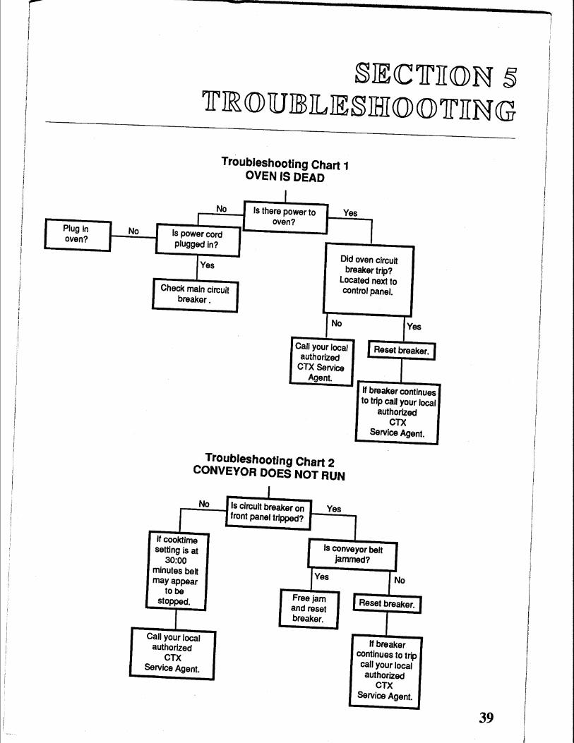
Troubleshooting Chart 1 OVEN IS DEAD
I No Is there power to Yes
oven?
I Is power cord plugged In?
Did oven circuit Yes breaker trip?
Located next to Check main circuit control panel.
breaker.
No Yes
Call your local I Reset breaker. I authorized
CTX Service Agent.
If breaker continues to trip call your local
authorized CTX
Service Agent.
Troubleshooting Chart 2 CONVEYOR DOES NOT RUN
I No Is circuit breaker on Yes
I front panel tripped?
If cooktime Is conveyor belt setting Is at
jammed? 30:00 minutes belt
fYes No may appear to be
Free jam Reset breaker. stopped.
and reset
r breaker. I
Call your local If breaker authorized
continues to trip CTX call your local Service Agent. authorized
CTX Service Agent.
39
SECTIONS· TROUBLESHOOTING
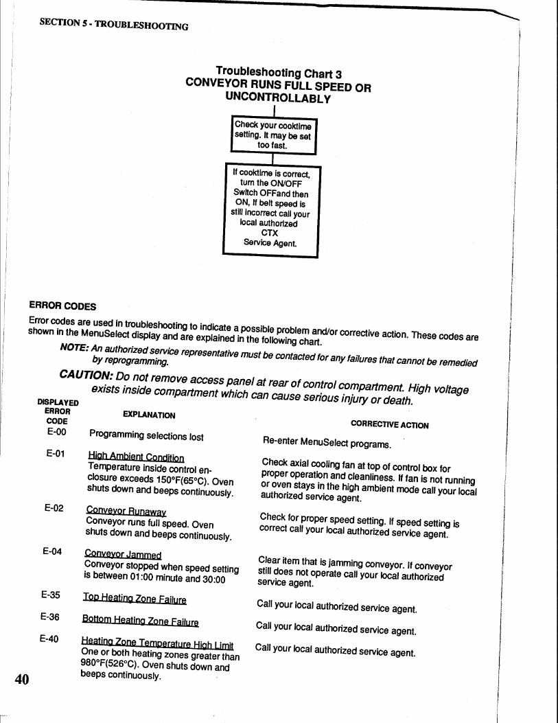
ERROR CODES
Troubleshooting Chart 3 CONVEYOR RUNS FULL SPEED OR
UNCONTROLLABLY
J Check your cooktlme setting. It may be set
too fast.
I If cooktime Is correct,
tum the ON/OFF Switch OFF and then ON, If belt speed Is
still incorrect call your local authorized
CTX Service Agent.
Error codes are used in troubleshooting to indicate a possible problem and/or corrective action. These codes are shown in the MenuSelect display and are explained in the following chart.
NOTE: An authorized service representative must be contacted for any failures that cannot be remedied by reprogramming.
40
CAUTION: Do not remove access panel at rear of control compartment. High voltage exists inside compartment which can cause serious injury or death.
DISPLAYED
ERROR EXPLANATION CODE
E-00 Programming selections lost
E-01 High Ambient Condition Temperature inside control enclosure exceeds 150°F(65°C). Oven shuts down and beeps continuously.
E-02 Conveyor Runawa)! Conveyor runs full speed. Oven shuts down and beeps continuously.
E-04 Conve)!or Jammed Conveyor stopped when speed setting is between 01:00 minute and 30:00
E-35 Top Heating Zone Failure
E-36 Bottom Heating Zone Fai!u~
CORRECTIVE ACTION
Re-enter MenuSelect programs.
Check axial cooling fan at top of control box for proper operation and cleanliness. If fan is not running or oven stays in the high ambient mode call your local authorized service agent.
Check for proper speed setting. If speed setting is correct call your local authorized service agent.
Clear item that is jamming conveyor. If conveyor still does not operate call your local authorized service agent.
Call your local authorized service agent.
Call your local authorized service agent. E-40
Heating Zone Temperature High Limit Call your local authorized service agent. One or both heating zones greater than 980°F(526°C). Oven shuts down and beeps continuously.
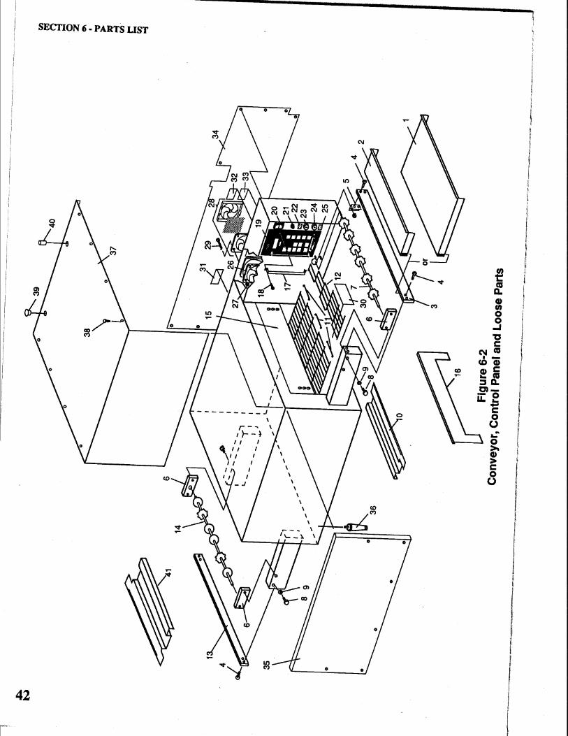
§JECClrll(Q)N CID J1D AIR lr§ ILll§lr
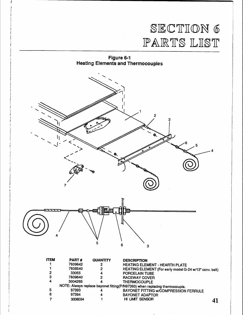
Figure 6·1 Heating Elements and Thermocouples
3
......_ ,I , 4
7
4
3
ITEM PART# QUANTITY DESCRIPTION 1 7609642 2 HEATING ELEMENT- HEARTH PLATE 1 7608540 2 HEATING ELEMENT (For early model G-24 w/13" conv. belt) 2 33055 4 PORCELAIN TUBE 3 7609640 2 RACEWAY COVER 4 3004265 4 THERMOCOUPLE
NOTE: Always replace bayonet fitting(P/N97393) when replacing thermocouple. 5 97393 4 BAYONET FITTING w/COMPRESSION FERRULE 6 97394 4 BAYONET ADAPTOR 7 3006034 1 HI. UMIT SENSOR 41
.,. N
C"l.l l'1l n ~
0 z ~ I ~ " ~ C"l.l t: C"l.l ~
Fig
ure
6-2
C
on
veyo
r, C
on
tro
l Pan
el a
nd
Lo
ose
Par
ts
--·
-·-·
· ···~-~w~~-.~-~
.. ~~~----~~-~.......,~-~-·-----~---~~____,__---~-........._.~-----~-~·------..-.-..~-~~-·-·-=-'----~-~---------------.--
-~--~------~--~-
Con
veyo
r, C
on
tro
l Pan
el a
nd L
oose
Par
ts
Par
ts L
ist
ITE
M
PA
RT
#
QU
AN
TIT
Y
DE
SC
RIP
TIO
N
1 70
0668
3 1
EX
IT T
RA
Y,
LON
G -
13
" (3
30m
m)
2 70
0547
1 1
EX
IT T
RA
Y,
SH
OR
T -
7"
(178
mm
) 3
7007
352
2 B
AR
-D
RIV
E E
ND
4
20
00
22
7
25
SC
RE
W, T
RU
SS
HE
AD
1 0-
32 x
1/2
" 5
7007
357
1 B
RA
CK
ET
BA
R
6 31
0033
5 3
BE
AR
ING
7
7610
247
1 D
RIV
E S
HA
FT
-C
ON
VE
YO
R
8 41
11A
8849
6
1/4-
20 x
3/8
" H
EX
HE
AD
BO
LT
9
F70
6A88
05
6 1/
4" F
LA
T W
AS
HE
R
10
7007
111
1 C
RU
MB
TR
AY
, B
EL
T S
UP
PO
RT
R.H
. 11
31
0117
5 3
MA
ST
ER
LIN
KS
12
3
10
11
74
1
CO
NV
EY
OR
BE
LT
(1 F
OO
T S
EC
TIO
N)
13
7005
446
1 B
AR
, ID
LER
EN
D
14
76
1024
8 1
IDLE
R S
HA
FT
, C
ON
VE
YO
R
15
7007
353
2 H
EA
T C
UR
TA
IN
16
7007
215
2 H
EA
T C
UR
TA
IN,
HIN
GE
D
17
70
0741
2 2
GU
AR
D,
KE
YP
AD
18
B
301A
8827
4
SC
RE
W,
TR
US
S H
EA
D 6
-32
X 1
/4"
19
7610
250
1 C
ON
TR
OL
ME
NU
SE
LEC
T
20
30
03
83
9
1 S
WIT
CH
, S
PS
T R
OC
KE
R
21
30
00
22
7
1 C
IRC
UIT
BR
EA
KE
R
22
24
0227
3 1
LAB
EL,
PR
OG
RA
M L
OC
KO
UT
2
3
76
10
28
7
1 K
EY
SW
ITC
H A
SS
EM
BLY
, L
OC
KO
UT
2
4
7610
288
1 K
EY
SW
ITC
H A
SS
EM
BLY
, M
OT
OR
RE
VE
RS
E
25
24
0227
2 1
LAB
EL,
CO
NV
EY
OR
RE
VE
RS
ING
2
6
30
02
68
6
1 F
AN
23
0V
AC
2
7
20
01
32
7
4 N
UT
2
8
30
00
33
0
1 F
IL T
EA
AS
SE
MB
LY,
FA
N
29
2
00
00
77
4
SC
RE
W,
FL
AT
HE
AD
6-3
2 X
2-1
/4"
30
3
10
15
65
1
DA
TA
PLA
TE
tl
:l
31
38
22
08
9
1 M
ET
AL,
CA
UT
ION
tf
j 3
2
32
10
08
1
LAB
EL,
WA
RN
ING
n
33
3
21
00
7
1 LA
BE
L, E
LEC
TR
ICA
L H
AZ
AR
D
~
0 3
4
7007
259
1 C
OV
ER
, R
EA
R
z 3
5
76
10
52
4
1 C
OV
ER
, F
RO
NT
0'
1 • 3
6
31
01
98
4
LE
G,4
"AC
UU
ST
AB
LE
~
37
70
0721
2 1
CO
VE
R,
MA
CH
INE
" 3
8
20
00
17
9
8 S
CR
EW
, T
RU
SS
HE
AD
10-
32 X
1/4
" ...,
39
31
0050
5 2
PL
UG
BU
TIO
N
tl:l
...
40
70
0311
5 2
PIN
, P
art o
f sta
ckin
g pi
n ki
t (#
G26
ST
AC
K)
t: tl:l
w
41
70
0711
2 1
CR
UM
B T
RA
Y,
BE
LT
SU
PP
OR
T L
.H.
...,
·-·--·
10
11
9 ~~
~
({)._ ~
'-a
5
1 6
3 4
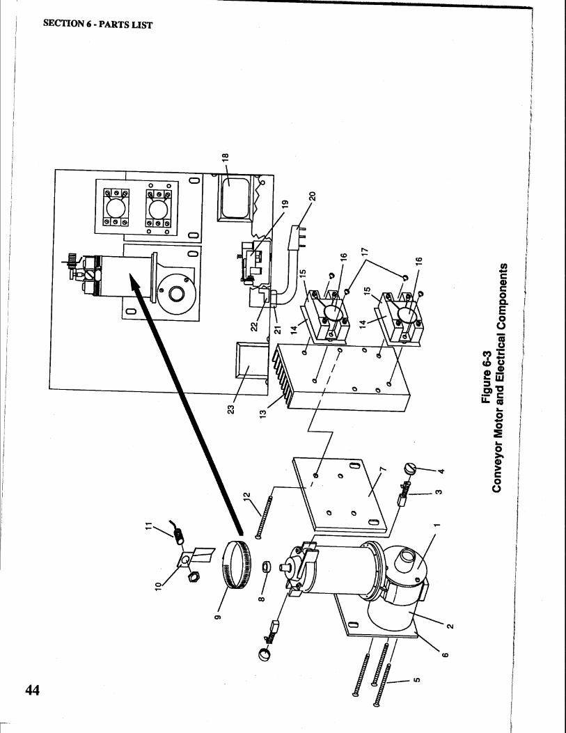
Con
veyo
r M
F
igur
e 6-
3 o
tora
nd
E le
ctri
cal C
ompo
nent
s
0'1
I
IT
EM
PAR
T#
QU
AN
TITY
D
ESC
RIP
TIO
N
1
7610
272
1
G
EA
R M
OTO
R
2 70
0539
0
1
BE
AR
ING
MO
TOR
MO
UN
T
3 30
0275
5
2
BR
US
H M
OTO
R
4 30
0275
6
2
CA
P B
RU
SH
5
2000
168
7
S
CR
EW
, FLA
T H
EA
D 8
-32
x 2”
6
7007
262
1
P
LATE
MO
TOR
MO
UN
T
7 70
0726
1
1
PLA
TE, R
ELY
MO
UN
T
8 97
217
1
M
AG
NE
T- C
ER
AM
IC -
4 P
OLE
(Mou
nt u
sing
any
met
al
com
patib
le fa
st s
ettin
g su
per g
lue
type
pro
duct
)
9 22
0416
1
H
ose
Cla
mp
10
7o
o6n3
1
S
EN
SO
R B
RA
CK
ET
11
76
1027
1
1
SE
NS
OR
AS
SE
MB
LY
12
2000
291
4
S
CR
EW
, FLA
T H
EA
D 1
0-32
x 2
-1/2
”
13
7007
263
1
H
EAT
SIN
K
14
2200
09
2
PTF
E P
AD
15
82
905
2
S
OLI
D S
TATE
RE
LAY
16
34
3010
8A
2
VAR
ISTO
R A
SS
EM
BLY
17
14
29A
8823
4
S
CR
EW
, RO
UN
D H
EA
D 8
-32
x 3/
8”
18
7608
516
1
TR
AN
SFO
RM
ER
32V
19
30
0291
8
1
RE
LAY
20
30
0112
6
1
CO
RD
AN
D P
LUG
AS
SE
MB
LY
21
3000
419
1
S
TRA
IN R
ELI
EF
22
87
037
1
G
RO
UN
D L
UG
23
97
397
1
TR
AN
SFO
RM
ER
, 12V
Con
veyo
r Mot
or a
nd E
lect
rical
Com
pone
nts
Part
s Li
st
45
SECTION 6 - PARTS LIST

SECTION 6 - PARTS LIST
NOTES
46
§JECCJrJI(Q)N II JEILJECCJrJEJICCAIL §CCIHIJEOOA JrJICC§
47
.c::..
oc
Grn
Blk
208/
240
VA
C
Blk
---~
----
~-·~------
19
Rel
ay
Ele
men
t-T
op
Ele
men
t-B
otto
m
On
/Off
Sw
•
7 8
6
S.S
.R.1
10 @
~:.
®
9
J1-3
1"~--------~~(~
@
®
~~-.-----~~~,~
I~
4
MO
DE
LG
-26
ELE
CTR
ICA
L S
CH
EM
ATI
C
19
Blk
/Wht
1-9
__
_ . _
__
2_0_8_/2_4_0_V_A_C__,_,~_,·~~---------
+
Blk
P.C
. B
oard
-+
m
-+
-
+
T/C
30
T/C
31
T/C
32
T/C
33
Top
Lef
t T
op R
ight
B
ot L
eft
Bot
Rig
ht
ell t!l
<":! ~ ......
I ~ til
<":! .., e <":! >
t"'
ell <":! =
t!l ;:.: ~ ~ <":!
1:"/l
0'¥-~,...__~-----~-·~~-----~~--~--
Plug
NE
MA
Sta
ndar
d 6-
50P
2 PO
le, 3
Wire
Gro
undi
ng
1 C
lrcuh
2 B
reak
er
~
fiil
l!ZI
7 8
~ ~
Con
trol
er
Grn
J1·7
R
ed J
1-14
a
k,i1
:6
--,d
..
l~~
Jl .
...
t~riT/) il
l Jl
-10
~-5
9 J1
-3
,fij..
lt-4 SS
R1
F.:._,
..-----'
li• ~~
jg
C: ~
I \...
____
_..15
1,..._
5 __
_ __
. G
nd L
ug
IW c
oiL
-------------'
HO
LE IN
CASEW~ ....
......
TOP
ELE
ME
NT
N.S
.
BO
TIO
M E
LEM
EN
T N
.S.
TOP
ELE
ME
NT
F.S
.
BO
TIO
M E
LEM
EN
T F.
S.
/ Em
TI
C T
op L
eft
~-----l2..!~.1--TIC
Top
Rlgh
1
'..:.
..
~
TIC
Bot
tom
Lef
t "------l:!,u
._
TIC
Bot
tom
Rig
h1
161 ~
~~~~~~
VA
RIS
TOR
'2
' :.
R';:
l~ ~
9
:J:I
N
CA
SE
WA
LL
HiU
mh
The
rmos
tat
Mo
del
G-2
6 W
irin
g D
iag
ram
20
8/24
0 V
AC
, 1
Ph,
50/
60 H
z
38
0V
AC
Gm
11
Ele
men
t-Top
Ele
men
t-Bot
tom
On/
OffS
w
4
'4'
To
'3'
J 10
\:
!I
.s. ~
9 1-
3 1"~--~------~~t~
@
®
~--·
·---
---~
~~~~
l~m
MO
DE
LG
-26
E
LE
CT
RIC
AL
SC
HE
MA
TIC
------
')Q
n \
li\C
~~~----
18 25
P.C
. B
oard
-+
-
+
1-1
-+
T/C
30
T/C
31
T/C
32
T/C
33
Top
Lef
t T
op R
ight
B
ot L
eft
Bot
Rig
ht
tiJ
\ ~ ~
~ ~ ~ l!j
I:"'
l!j ~
""3 ~ ~ >
I:"'
tiJ
~ = ~ ~ n ti
J
1 C
lrw
tt
2 B
IINik
er
1!¥
ffil
l.§J2
11
21
7 8
Lock
out ~
Key
Sw
llch
Con
trole
r
r- ~
J2
Grn
1-
7 fl!
!!. 1
-14
si(J
i':ii'
~l
s
1~!
:IE
. _;!
!... Jl
Mo
tor
ffi
J1-1
0
~-5
9 J1
-3
liQ
L!1
-4
SSR
1
HO
LE IN
CASEW~ ...
......
.........
I
TOP
ELE
ME
NT
N.S
.
BO
TTO
M E
LEM
EN
T N
.S.
TOP
ELE
ME
NT
F .S
.
BO
TTO
M E
LEM
EN
T F.
S.
/ ,.. ..
... .....
....
lsi
~IN
CA
SE
WA
LL
HI L
lmil
The
rmos
tat
Mo
del
G-2
6 E
xpo
rt W
irin
g D
iag
ram
38
0 V
AC
, 3
Ph
, 5
0 H
z
I I
I I L
CTX® A Middleby Company
Part No. 310-2547 Price $15.00
For more information on the complete line of CTX products, contact your Food Service Equipment Dealer, or write to us at the address below.
Genuine Parts Protect YOU All-Ways I
CTX® 1400 Toastmaster Drive Elgin, IL 60120 (708) 7 41-3300
Printed in U.S.A.