owner's manual - track n go
TRANSCRIPT

OWNER'S MANUAL
MODEL:TG-13


Scan
the
codeor
follow
the
linkto
watch
the
install
videoreference.
http://www.youtube.com/watch?v=sKQXE-j0eaA

http://www.youtube.com/watch?v=YAECGVcEGu8
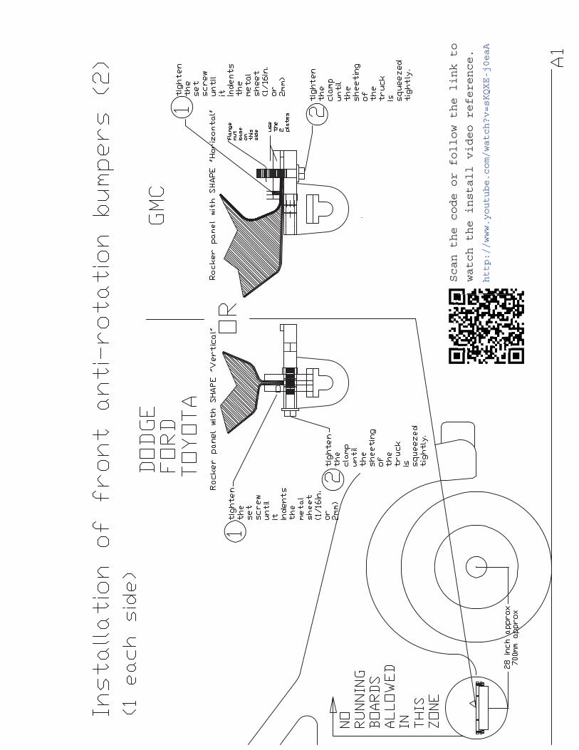
Scan the code or follow the link to watch the install video referance.


Section B
TRACKS
PREPARATION
Sec
tio
n B
T
rack
Pre
par
atio
n


Section C
How to Install the tracks on the vehicle
General recommendations and safe operation guidelines to read before using the system the first time.
Sec
tio
n C
H
ow
to
inst
all o
n v
ehic
le


C-3
GENERAL RECOMMENDATIONS AND SAFE OPERATION GUIDELINES TO READ BEFORE USING
THE SYSTEM THE FIRST TIME 1. The operator must watch the installation videos and read this entire section before using the track system. 2. Whenever the system is being used, the operator must conduct an inspection of all 4 tracks and check if all the parts holding each of the 4 tracks on the vehicle are secured. 3 . The vehicle must always be used in 4x4 mode . Always use the 4x4 LO mode in the snow. The 4x4 HI mode is only allowed on hard surfaces or paved roads. For automatic transmission vehicles , always use manual mode M- 1, M- 2, M -3 ... . For vehicles with a gasoline engine, maintain a constant engine revolution around 2500-3000 rpm and do not exceed 3500 rpm (for diesel type engines 1800 to 2500 rpm) 4. For use in steep mountainous terrain or in a towing situation, it is highly recommended to install an extra automatic transmission oil cooler. Because the operating speeds with Tracks are generally slow, make sure that the engine radiator fan is functional and in good condition. The fan is the main cooling element of your engine at speed 30kmh (18 MPH) and lower. 5. If the track system must remain outside, refer to the following page C-4 for the recommended shutdown procedure. When the system is left outside , you must start SLOWLY (always in LO Mode) moving forward and backward until the tracks begin to move. It is normal that the tracks come in contact with the bumper stoppers. This contact with the bumper stoppers will help you break the tracks free.

C-4
6. Shutdown procedure when the tracks stay outside: The inside of Track N Go system is equipped with a mechanism of scrapers and molded components which prevent ice formation during use. However, when the system is being left outside for an extended time at temperatures below 0 Celsius (32 F) or lower, You must conduct a procedure of "snow and ice removal" of the system. To do this, you must ride on hard packed snow or pavement over a minimum distance of 1500 feet (500 m) to remove snow and ice which accumulated within the system.
When you are in an off road area and it is not possible for you to do the "snow and ice removal" procedure you must make sure that you do it partially as followed: a) Remove the snow and ice from your tracks by compacting the snow you are driving on and making your tracks in the snow wider. To do this go forward and backward over a distance of 50 feet (15 m) until your tracks are cleared of snow and that you are now on a hard and wide packed surface. b) Finish by going forward and backward 1 or 2 times the distance of the centre of your wider hard packed track so that the snow and ice is removed from the system.

C-5
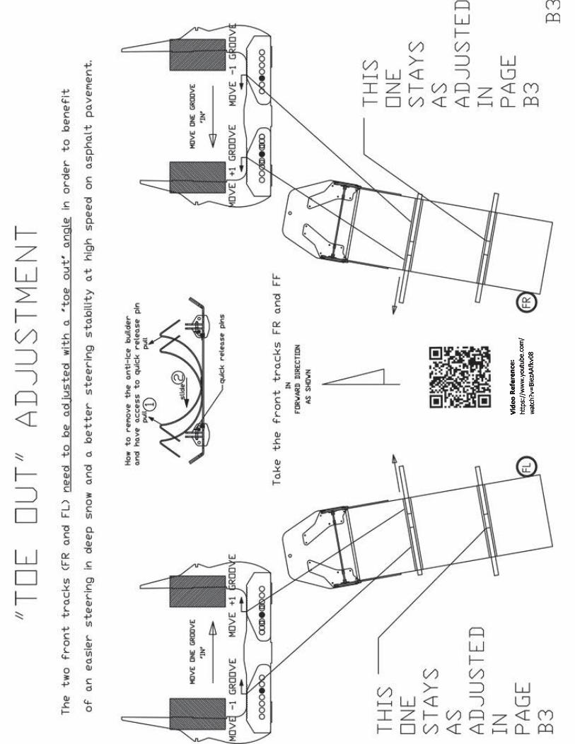
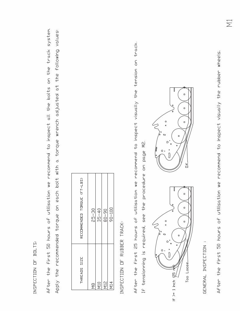
7. Verification of the Toe Out: Before using the system you should always check the toe out of the front tracks with a tape measure. The toe out must be in between ½. and 1 ½ inches. (12 mm and 40 mm). If it is not the case, you must review the initial installation procedure (page B3) and check if you have adjusted the side guide roller on track FR and FL as specified in the procedure. Once this is done if the toe out is still not adjusted correctly, you will need to check the alignment of your vehicle. NEVER USE THE TRACK SYSTEM IF THE TOE OUT IS LESS THAN ½ (12 mm) OR NEGATIVE.

C-6
8. Periodic verification of the tensioners: The exterior and interior tensioners hold your tracks in place. If any of these clips is missing, you can lose a track and damage your vehicle. Check periodically if they are secured correctly:
9. Always check that all quick release pins are locked by pulling on them once they are installed. Lubricate them when in storage.

C-7
10. Lateral inclination usage: The track system increases the centre of gravity of your vehicle by 8 inches. (20 cm). Do not place the vehicle in a position greater than 10 degrees to avoid destabilizing the weight of the vehicle on 2 wheels and avoid transferring the power to the tracks that have less traction. To get the best performances the tracks require that all 4 wheels work simultaneously. A self-locking rear differential is the minimum requirement to use the track system. Adding a front differential lock is also recommended if you are using the system in situations where angles are greater than 10 degrees.
11. Traveling with tracks: The power required to move in deep snow significantly increases fuel consumption and requires more from the mechanics of your vehicle. Generally, we recommend that the traveling surface is groomed if the snow cover exceeds 50 cm (20 in.) In addition, for safe travel we recommend a corridor setting with stakes (Poles). The maintenance of your roads (trails) will provide comfort to users and will lengthen the use of your tracks in springtime. If you are using a conventional 4x4 vehicle with a rear differential lock system, we recommend that you groom your roads (trails) after a major snowfall of (20-30 cm (8-12 in) in order to increase efficiency and reduce your operating costs. If you plan to use the system in deep snow on a non-groomed road (trail), it is strongly recommended to use an electronic, selectable differential lock system (E Locker) on the front axle. This will provide full traction on all 4 wheel simultaneously.

C-8
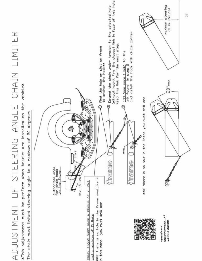
12. Steering angle: The chains installed at the rear of the two front tracks are there to limit the steering angle. It is very important to limit the steering angle of the tracks for two reasons: 1) When the steering angle is too high this will slow down the vehicle while turning in the snow. A maximum 10 to 15 degrees are recommended for effective steering; 2) When the steering angle is too high it can cause contact between the track system and the frame or other components of the vehicle which could cause damage to the vehicle and / or the track.
13. Recommended operating speed.: 4x4 LO: In snow 5-10 MPH (10-20 Km/h) 4x4 HI: hard packed snow or paved roads 5 to 40 MPH (10 to 65 Km/h) Maximum speed: 40 mph (65 km/h)

C-9
14. Recommended tires types and general recommendations: We recommend to use winter tires or 4 seasons tires. "MUD TIRES" are not recommended. While using the Tracks the tires are cooled by water and snow. When the track system is used on a road without snow or without water you will need to pay attention to the temperature of the tires. If the tire temperature is above 80 degrees Celsius (175F) you must reduce your speed. Do not temporarily "overheat" the tire’s tread as this will have the effect of shortening its lifespan. If you plan to travel at high-speed on paved roads often, we recommend a 4 seasons tire with a harder rubber compound rather than a winter tire with a softer compound. Highly recommended tires to use with Track N Go: Winter tires: General Tire Altimax Arctic GoodYear UltraGrip Ice WRT 4 seasons tires: BF Goodrich Rugged Trail Goodyear Wrangler LT 15. Air pressure in tires: Make sure that the air pressure in the tires is the pressure recommended by the manufacturer of the vehicle. For 1/2 ton vehicles our recommendation is 30-35 psi and for 3/4 and 1 ton vehicles we recommend 45 psi max. Never exceed 50 PSI. 16. Tracks break in time: During the first 10 hours of use, the system requires 10 to 15% more power. After 25 hours, the components are broken in and the system will work more freely. 17. Restriction of use: The Track N Go track system is designed for use in the snow. It is also designed to run on hard surfaces like paved roads so that you can travel between areas which have snow. The system is also compatible with the sand. However, the design and the exclusive external drive of the tracks are not design to be used in the mud and especially in the rocky or clay type mud.

Section D
SAFETY CHAINS
ADJUSTMENT
Sec
tio
n D
S
afet
y C
hai
ns
adju
stem
ent

Section M
MAINTENANCE MANUAL
AND ACCESSORIES
Sec
tio
n M
M
ain
ten
ance
an
d a
cces
sori
es

Scanthecodeorfollowthe
linktowatchtheinstall
videoreference.
http://www.youtube.com/watch?
v=SkpmEdB5cZ0


Section P
PART NUMBERS
AND EXPLODED VIEW
Sec
tio
n P
P
arts
exp
lod
ed v
iew

TG DRIVES ASSY
1
2
34
5
7
8
9
10
11
12
13
14
15
16
17
18
19
20
21
22 23
24
25
26
29
30
31
3233
34
35
36
28
37
38
39
34
36
6
28
27

P-2

1
2
3
4
TG GUIDE ASSY
P-3

12
3
12
REF.Part NumberQty
Part Description
130X52X7
230X52X7 SHAFT OIL SEAL NITRILE
2CA.62052RS
4BEARING 6205 CANIMEX USA 80% BACON GREASE LABOR ASSY
3TG-001SA
1DRIVER SUB-ASSY YELLOW ZINC PLATED
4TG-003
1ALUMINIUM SHAFT
4
TG-01A
P-4

12
3
2
1
4
TG-02A
REF.Part NumberQty
Part Description
130X52X7
230X52X7 SHAFT OIL SEAL NITRILE
2CA.62052RS
4BEARING 6205 CANIMEX USA 80% BACON GREASE LABOR ASSY
3TG-009SA
1TUBE WITH 5 INCH WHEELS
4TG-003
1ALUMINIUM SHAFT
P-5
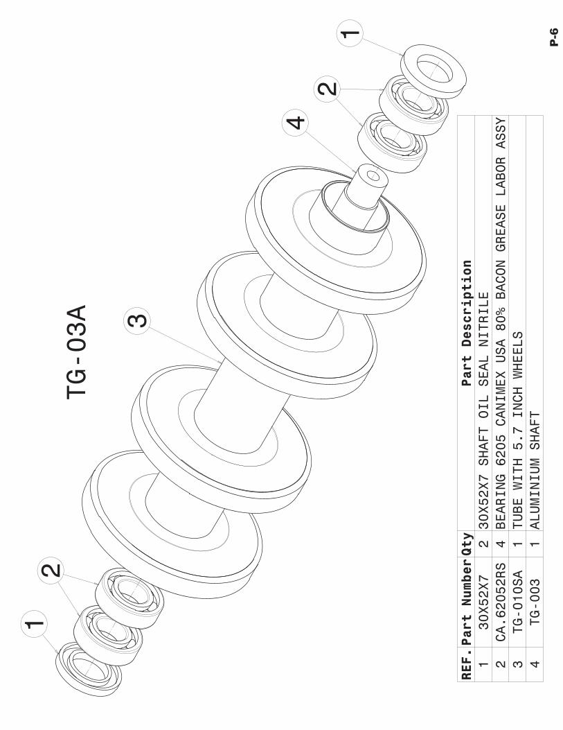
TG-03A
12
3
12
4
REF.Part NumberQty
Part Description
130X52X7
230X52X7 SHAFT OIL SEAL NITRILE
2CA.62052RS
4BEARING 6205 CANIMEX USA 80% BACON GREASE LABOR ASSY
3TG-010SA
1TUBE WITH 5.7 INCH WHEELS
4TG-003
1ALUMINIUM SHAFT
P-6

12
3
124
TG-04A
REF.Part NumberQty
Part Description
130X52X7
230X52X7 SHAFT OIL SEAL NITRILE
2CA.62052RS
4BEARING 6205 CANIMEX USA 80% BACON GREASE LABOR ASSY
3TG-011SA
1TUBE WITH 8 INCH WHEELS
4TG-003
1ALUMINIUM SHAFT
P-7
1
2
4
5
3
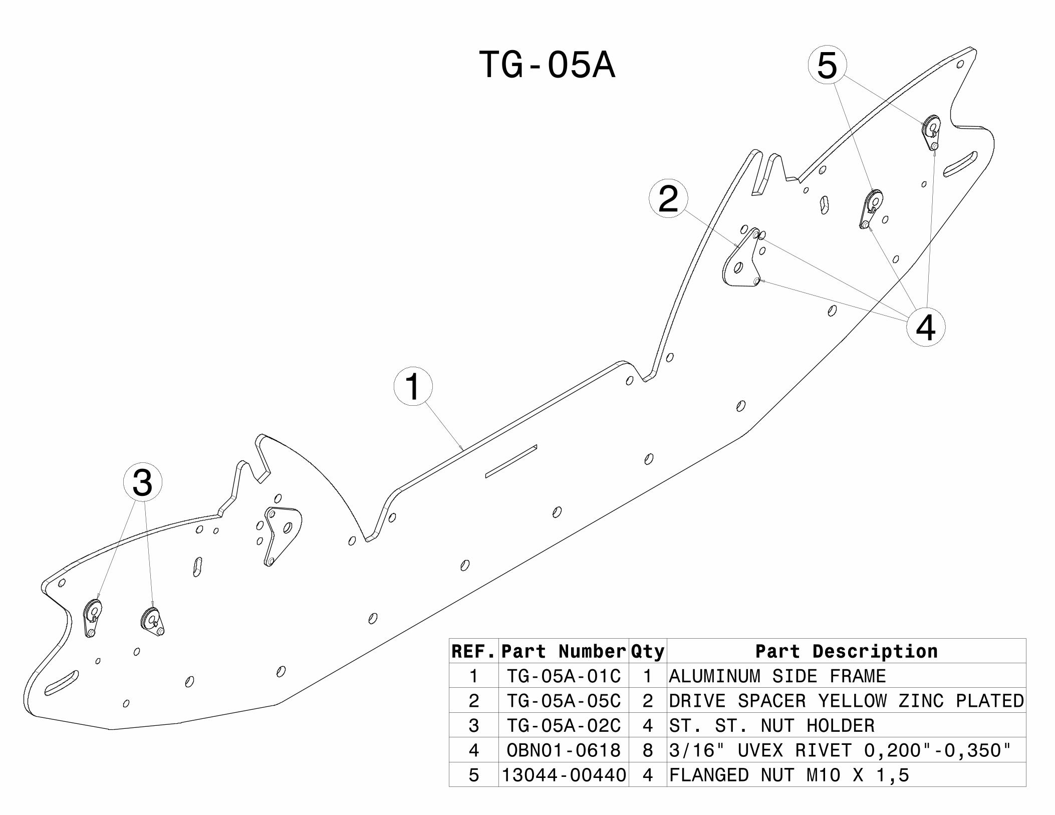
TG-05A
REF. Part Number Qty Part Description1 TG-05A-01C 1 ALUMINUM SIDE FRAME2 TG-05A-05C 2 DRIVE SPACER YELLOW ZINC PLATED3 TG-05A-02C 4 ST. ST. NUT HOLDER4 OBN01-0618 8 3/16" UVEX RIVET 0,200"-0,350"5 13044-00440 4 FLANGED NUT M10 X 1,5
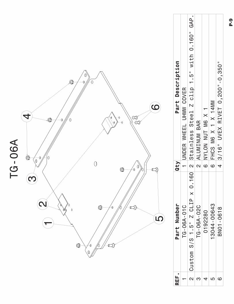
TG-06A
12
34
6
REF.
Part Number
Qty
Part Description
1TG-06A-01C
1UNDER WHEEL UHMW COVER
2Custom S/S 1.5" Z CLIP x 0.160
2Stainless Steel Z clip 1.5" with 0.160" GAP.
3TG-06A-02C
2ALUMINUM BAR
40192280
6NYLON NUT M6 X 1
513044-00643
6FHCS M6 X 1 X 14MM
6BN01-0618
43/16" UVEX RIVET 0,200"-0,350"
5
P-9

TG-07A
1
2
3
REF.Part NumberQty
Part Description
1TG-007SA
1CLIMBER FRAME
2TG-07A-01B
1CLIMBER UHMW PLATE BENT
3OBE34-0622
12A3/16 POP RIVET STAVEX LG.FL 0.250-0.500
P-10

TG-08A
7
6
REF.Part NumberQty
Part Description
1TG-08A-01
1ROLLER ALUMINUM SHAFT
230X52X7
230X52X7 SHAFT OIL SEAL NITRILE
3CA.62052RS
2BEARING 6205 CANIMEX USA 80% Bacon grease
4TG-08A-02
1UHMW ROLLER
51166814
1O-RING 7/8 ID x 1 OD x 1/16 dia.
6TG-08A-03
2CHROME PLATED RING
713044-00378
1BHCS M8 X 1,25 X 12MM
1
23
4
5
P-11

TG-09A-L
1
2
3
REF.Part NumberQty
Part Description
1TG-00A-04B
1UHMW SNOW DEFLECTOR BENT
2APL5-47B2S-A
1QUICK RELEASE LOCK PIN 5/16" DIA. X 5/8" LG + LANYARD 6 INCH
3OBN01-0618
13/16" UVEX RIVET 0,200"-0,350"
49600K54
2GROMMET 5/16" ID, 11/16" OD, 1/4" THICKNESS,
1/2"Hole
4
P-12
1
2
3
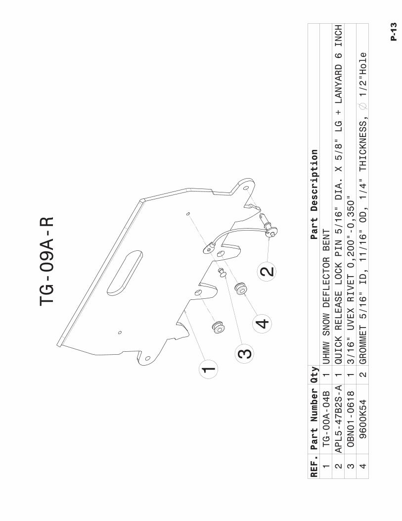
TG-09A-R
REF.Part NumberQty
Part Description
1TG-00A-04B
1UHMW SNOW DEFLECTOR BENT
2APL5-47B2S-A
1QUICK RELEASE LOCK PIN 5/16" DIA. X 5/8" LG + LANYARD 6 INCH
3OBN01-0618
13/16" UVEX RIVET 0,200"-0,350"
49600K54
2GROMMET 5/16" ID, 11/16" OD, 1/4" THICKNESS,
1/2"Hole
4
P-13

TG-20A
REF.Part NumberQty
Part Description
1TG-020SA
1STEEL SUB-ASSY SUPPORT GRAY PAINTED
2TG-20A-01P
1RUBBER SUPPORT GRAY PAINTED
3TG-20A-02
1EXTRUDED RUBBER 1 3/4" X 2" X 6" LG
413044-00441
2BHCS M8 X 1,25 X 35MM
513044-00446
2NYLON NUT M8 X 1,25
1
2
34
5
P-14

TG-21A
1
2 4
5
6
3
7
8
REF. Part Number Qty Part Description1 TG-21SA 1 SUB-ASSY REAR BUMPER CLAMP SLIDER GRAY PAINTED2 TG-21A-01P 2 LOWER CLAMP GRAY PAINTED3 21830 4 SQUARE HEAD CAP SCREW 1/2-NC X 3" LG4 0167034 4 NYLON NUT 1/2-NC5 11115874 1 HHFCS M12 X 1,75 X 30MM6 G42650000YZ0000 1 NUT M12 X 1,757 21889 4 SQUARE HEAD CAP SCREW 1/2-NC X 4" LG (LONGER EXTRA SET)8 TG-21A-02P 1 EXTRA LOWER CLAMP GRAY PAINTED (THINNER 1/8)
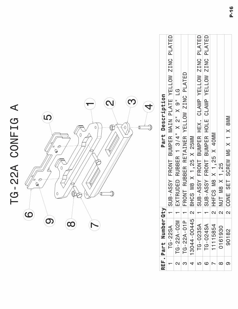
TG-22A CONFIG A 1 2 3
4
5
6
79 8
REF.Part NumberQty
Part Description
1TG-22SA
1SUB-ASSY FRONT BUMPER MAIN PLATE YELLOW ZINC PLATED
2TG-22A-02M
1EXTRUDED RUBBER 1 3/4" X 2" X 9" LG
3TG-22A-01P
1FRONT RUBBER RETAINER YELLOW ZINC PLATED
413044-00445
2BHCS M8 X 1,25 X 25MM
5TG-023SA
1SUB-ASSY FRONT BUMPER HEX. CLAMP YELLOW ZINC PLATED
6TG-024SA
1SUB-ASSY FRONT BUMPER HOLE CLAMP YELLOW ZINC PLATED
711115854
2HHFCS M8 X 1,25 X 40MM
80161930
2NUT M8 X 1,25
990182
2CONE SET SCREW M6 X 1 X 8MM
P-16

TG-22A CONFIG B
1
2
3
4
5
6
8
7
REF.Part NumberQty
Part Description
1TG-22SA
1SUB-ASSY FRONT BUMPER MAIN PLATE YELLOW ZINC PLATED
2TG-22A-02M
1EXTRUDED RUBBER 1 3/4" X 2" X 9" LG
3TG-22A-01P
1FRONT RUBBER RETAINER YELLOW ZINC PLATED
413044-00445
2BHCS M8 X 1,25 X 25MM
5TG-023SA
1SUB-ASSY FRONT BUMPER HEX. CLAMP YELLOW ZINC PLATED
611115854
2HHFCS M8 X 1,25 X 40MM
70161930
2NUT M8 X 1,25
890182
2CONE SET SCREW M6 X 1 X 8MM
P-17
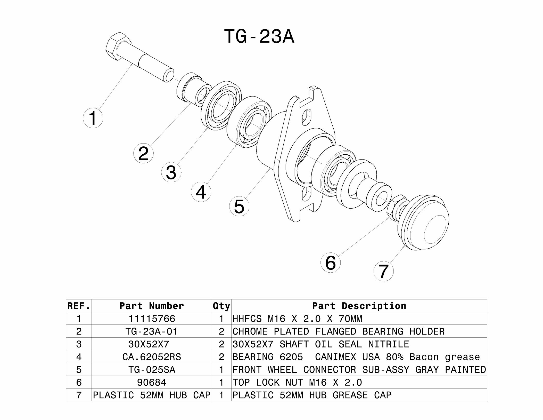
TG-23A
REF. Part Number Qty Part Description1 11115766 1 HHFCS M16 X 2.0 X 70MM2 TG-23A-01 2 CHROME PLATED FLANGED BEARING HOLDER3 30X52X7 2 30X52X7 SHAFT OIL SEAL NITRILE4 CA.62052RS 2 BEARING 6205 CANIMEX USA 80% Bacon grease5 TG-025SA 1 FRONT WHEEL CONNECTOR SUB-ASSY GRAY PAINTED6 90684 1 TOP LOCK NUT M16 X 2.07 PLASTIC 52MM HUB CAP 1 PLASTIC 52MM HUB GREASE CAP
1
23
45
6 7

TG-24A
1
2
3
REF.Part NumberQty
Part Description
145214
1THREADED CHAIN CONNECTOR 5/16"
2TG-24A-01
1RUBBER SLEEVE CHAIN PROTECTOR X 14" LONG
33807-0016-20
11/4" CHAIN SAE 70 X 20 LINKS
P-19
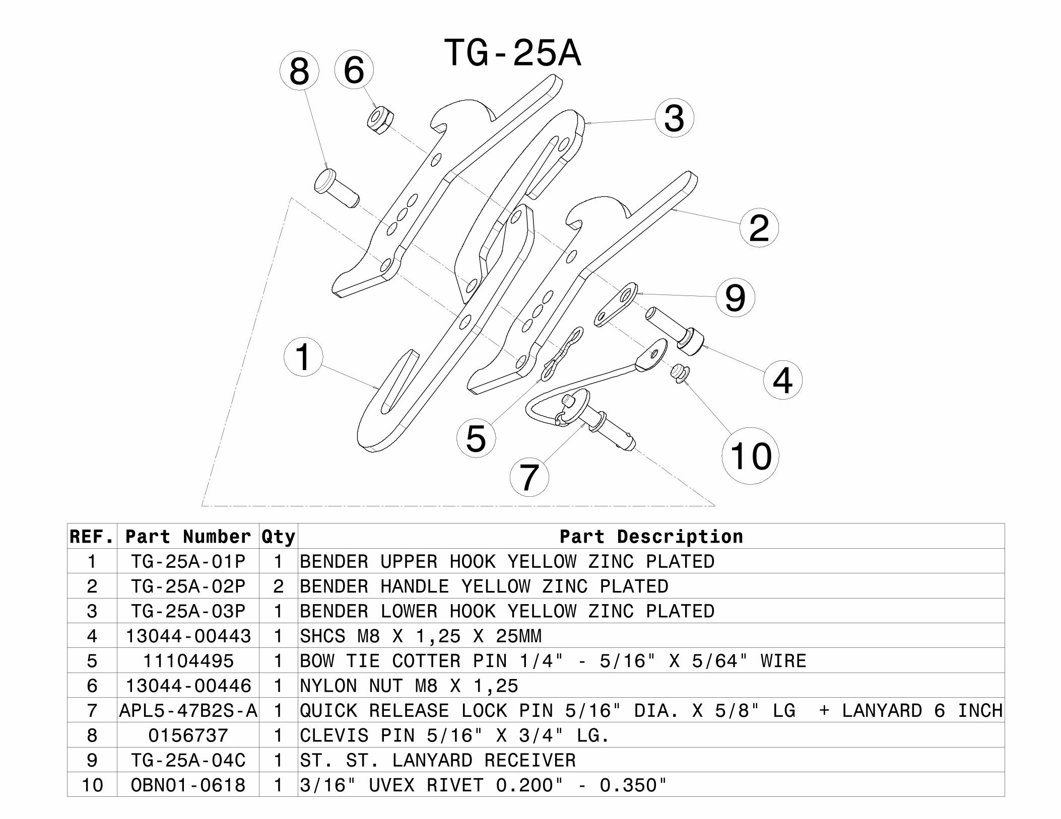
TG-25A
1
2
3
4
5
6
7
8
9
10
REF. Part Number Qty Part Description1 TG-25A-01P 1 BENDER UPPER HOOK YELLOW ZINC PLATED2 TG-25A-02P 2 BENDER HANDLE YELLOW ZINC PLATED3 TG-25A-03P 1 BENDER LOWER HOOK YELLOW ZINC PLATED4 13044-00443 1 SHCS M8 X 1,25 X 25MM5 11104495 1 BOW TIE COTTER PIN 1/4" - 5/16" X 5/64" WIRE6 13044-00446 1 NYLON NUT M8 X 1,257 APL5-47B2S-A 1 QUICK RELEASE LOCK PIN 5/16" DIA. X 5/8" LG + LANYARD 6 INCH8 0156737 1 CLEVIS PIN 5/16" X 3/4" LG.9 TG-25A-04C 1 ST. ST. LANYARD RECEIVER10 OBN01-0618 1 3/16" UVEX RIVET 0.200" - 0.350"

REF.Part NumberQty
Part Description
1TG-026SA
1FRONT SECTION LOADING RAMP SUB-ASSY YELLOW ZINC PLATED
2TG-027SA
1VERTICAL SECTION LOADING RAMP SUB-ASSY YELLOW ZINC PLATED
3TG-028SA
1MIDDLE SECTION LOADING RAMP SUB-ASSY YELLOW ZINC PLATED
4TG-029SA
1REAR SECTION LOADING RAMP SUB-ASSY YELLOW ZINC PLATED
513044-00375
4BHCS M10 X 1,5 X 30MM
613044-00447
4NYLON NUT M10 X 1,5
798320A488
2Zinc-Plated Steel Quick-Release Pin 1/2" Dia, 0.8" L
12
3
4
5
6
7TG-26A
P-21

REF.Part NumberQty
Part Description
1TG-08A
4ROLLER ASSY
213044-00375
8BHCS M10 X 1,5 X 30MM
313044-00447
8NYLON NUT M10 X 1,5
4TG-005SA
1OUTSIDE WHEEL GUIDE SUB-ASSY YELLOW PAINT
TG-27A
12
3
4
P-22

TG-28A
1
2
3
REF. Part Number Qty Part Description1 TG-08A 4 ROLLER ASSY2 13044-00375 8 BHCS M10 X 1,5 X 30MM3 13044-00447 8 NYLON NUT M10 X 1,54 TG-006SA 1 INSIDE WHEEL GUIDE SUB-ASSY YELLOW PAINT5 TG-00A-30 1 CAUTION DECAL
54

1
ADAPTOR KIT PARTS
2
3
WARRANTY All the parts of the Track N Go track system are covered by the warranty
for a period of one winter season against any problem related to its assembly or construction.
In the case of a repair under warranty the labour costs of repair is not covered by the manufacturer.
The manufacturer reserves the right to require that the customers carrying out the repairs send back any parts declared or suspected to be defective and / or subject of abusive use.
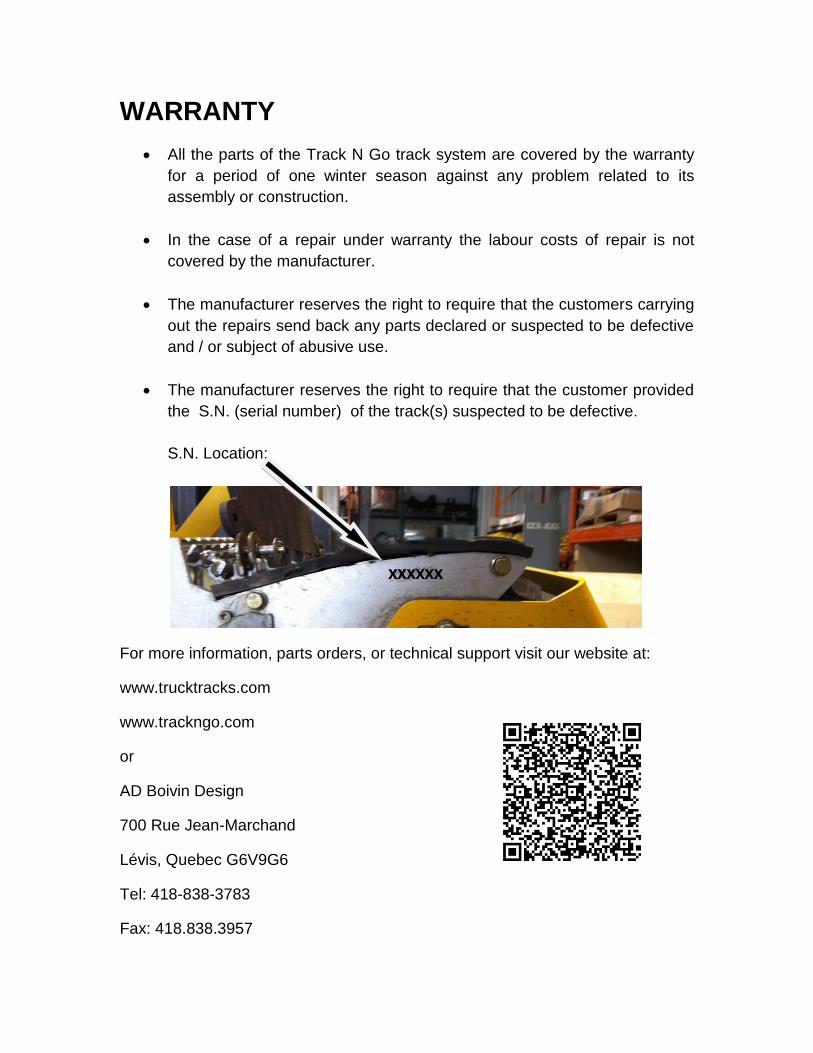
The manufacturer reserves the right to require that the customer provided the S.N. (serial number) of the track(s) suspected to be defective. S.N. Location:
For more information, parts orders, or technical support visit our website at:
www.trucktracks.com
www.trackngo.com
or
AD Boivin Design
700 Rue Jean-Marchand
Lévis, Quebec G6V9G6
Tel: 418-838-3783
Fax: 418.838.3957