track standards - gosite.ca€¦ · this is the first edition of the, go transit track standards...
TRANSCRIPT

TRACK STANDARDS RC-0506-02TRK
June 2016
GO TRANSIT TRACK STANDARDS
RC-0506-02TRK
Publication Date: June 2016
COPYRIGHT © 2016
Metrolinx, an Agency of the Government of Ontario
The contents of this publication may be used solely as required for and during a project assignment from Metrolinx or for and during preparing a response to a Metrolinx procurement request. Otherwise, this publication or any part thereof shall not be reproduced, re-distributed, stored in an electronic database or transmitted in any form by any means, electronic, photocopying or otherwise, without written permission of the copyright holder. In no event shall this publication or any part thereof be sold or used for commercial purposes. The information contained herein or otherwise provided or made available ancillary hereto is provided “as is” without warranty or guarantee of any kind as to accuracy, completeness, fitness for use, purpose, non-infringement of third party rights or any other warranty, express or implied. Metrolinx is not responsible and has no liability for any damages, losses, expenses or claims arising or purporting to arise from use of or reliance on the information contained herein.

GO TRANSIT TRACK STANDARDS
TRACK STANDARD RC-0506-02TRK June 2016 Revised: 2016-05-09
PREFACE This is the first edition of the, GO Transit Track Standards RC-0506-02TRK June 2016. It is adapted from CN Engineering Track Standards as per the agreement between Metrolinx and CN on March 28, 2013. In accordance with the agreement, Metrolinx is authorized to affix the name of Metrolinx/GO Transit to the CN Standards, shall remove all references to CN and update/ modify the standards to Metrolinx/GO Transit Standards.
The purpose of the GO Transit Track Standards is to ensure that Metrolinx and GO Transit owned and operated track is constructed and maintained utilising safe, cost effective and efficient methods to meet project delivery timelines, and meet on-time operational performance goals. Furthermore, a consistent approach in the application of GO Transit owned track standards shall reduce disputes during the design and construction phases of a project, enhance the long term safety, reliability and extend the useful service life of the track infrastructure.
The technical content within the, GO Transit Track Standards RC-0506-02TRK was modified/developed by the Metrolinx / GO Transit Track Standards Committee which includes specialized subject matter experts.
Note
The GO Transit Track Standards RC-0506-02TRK June 2016 is intended for use by suitably qualified professionals. It is not a substitute for coordination and compliance with all applicable local codes, standards, manuals, and approvals for fire protection, life safety, and security measures that are part of the planning, design and implementation of a railway.
Suggestions for revisions and improvement
Suggestions for revision or improvement can be sent to the Metrolinx / GO Transit Track Standards Committee, Attention: Senior Manager of Track and Structures, Rail Corridors (who shall have the deciding vote). Be sure to include a description of the proposed change, background of the application and any

GO TRANSIT TRACK STANDARDS
TRACK STANDARD RC-0506-02TRK June 2016 Revised: 2016-05-09
other useful rationale or justification. Be sure to include your name, company affiliation (if applicable), e-mail address, and phone number.
GENERAL REQUIREMENTS 1. The maintenance and construction standards and
practices contained herein shall apply to all trackage and rights-of-way owned or operated by GO Transit (“the Railway”), and UP Express, which are divisions of Metrolinx, and are intended as the requirements but not intended to replace or supersede the Transport Canada (TC) Track Safety Rules.
2. Changes in railway standards or practices that do not conflict with TC standards may be implemented on a phased schedule or program, at the Railway’s discretion.
3. All new or modified materials or equipment shall be subjected to a service test, unless otherwise directed by the Rail Corridors, Senior Manager of Track and Structures.
4. Under the requirements of these Standards, and where appropriate, the Rail Corridors Senior Manager of Track and Structures may delegate their authority to a designated individual.
5. Designated Authority, as described above, shall be summarized at the end of this document.
6. The most current version of the GO Track Standards shall be located on the MYLINX intranet site at: http://mylinx/sites/RailServ/en/Pages/Track-Standards.aspx, under title “Track Standards”.
These standards are effective as of June 1st, 2016

GO TRANSIT TRACK STANDARDS
TRACK STANDARD RC-0506-02TRK June 2016 Revised: 2016-04-20
CONTENTS Section 1 - Requirements ......................................................... 1-1
1.1. General ................................................................... 1-1 1.2. Track Standards ..................................................... 1-1 1.3. Recommended Methods ........................................ 1-2 1.4. Miscellaneous ......................................................... 1-2
Section 2 - Definitions ............................................................... 2-1
Section 3 - Rail ....................................................................... 3-11
3.1. General Requirements ......................................... 3-11 3.2. Laying Rail ............................................................ 3-14 3.3. Rail Wear .............................................................. 3-18 3.4. Continuous Welded Rail ....................................... 3-19 3.5. Maintenance of Thermal Stress in Rail ................ 3-21 3.6. Destressing Rail ................................................... 3-23 Recommended Method 3205-0: Destressing CWR ......... 3-27 3.7. Failures in CWR ................................................... 3-30 3.8. Repairing Pull-Aparts ............................................ 3-31 3.9. Repairing a Track Buckle ..................................... 3-33 3.10. Track Buckling Causes and Prevention .......... 3-35 3.11. Remedial Action for Broken Rail or Defect ..... 3-37 3.12. Defective Rails ................................................ 3-41 3.13. Defects at CAD Welds .................................... 3-43 3.14. Crushed Heads or Localized Surface Collapse and Rail End Batter .......................................................... 3-44 3.15. Authorizing Movements Over Rail Breaks ...... 3-46 Recommended Method 1303-0 – Classification of Rail ... 3-52 Recommended Method 3700-3 - Unloading Rail ............. 3-60
Section 4 - Joints ...................................................................... 4-1
GO TRANSIT TRACK STANDARDS
TRACK STANDARD RC-0506-02TRK June 2016 Revised: 2016-05-09
4.1. General Information ................................................ 4-1 4.2. Conventional Joints ................................................. 4-1 4.3. Insulated Joints ....................................................... 4-2 4.4. Compromise Rails and Joints ................................. 4-3 Recommended Method 3700-0 – Drilling Holes in Rail ...... 4-5
Section 5 - Rail Grinding ........................................................... 5-1
5.1. Rail Grinding with Self Propelled Grinding Machines5-1 5.2. Frog and Switch Grinding ....................................... 5-3 5.3. Rail Grinding Near Bridges and Structures ............. 5-4
Section 6 - Rail Lubrication ....................................................... 6-1
6.1. Way-Side Lubricators .............................................. 6-1 6.2. Lubricating Products ............................................... 6-4
Section 7 - Field Welding .......................................................... 7-1
7.1. General Information ................................................ 7-1 7.2. Thermite Welding .................................................... 7-2 7.3. Flash Butt Welding (Arc Welding) ........................... 7-4 7.4. Cold Weather Welding ............................................ 7-4 7.5. Additional Safety Requirements .............................. 7-6
Section 8 - Ties ......................................................................... 8-1
8.1. Timber Tie Installation and Maintenance ................ 8-1 8.2. Concrete Tie Installation and Maintenance ............ 8-9 8.3. Concrete Tie Repair Procedure ............................ 8-13 8.4. Steel Tie Installation and Maintenance ................. 8-15 8.5. Composite Tie Installation and Maintenance ........ 8-15 8.6. Other Types of Ties............................................... 8-17
Section 9 - Plates and Fasteners .............................................. 9-1
9.1. Tie Plates ................................................................ 9-1 9.2. Rail Anchors ............................................................ 9-2

GO TRANSIT TRACK STANDARDS
TRACK STANDARD RC-0506-02TRK June 2016 Revised: 2016-05-09
9.3. Derails ..................................................................... 9-5 9.4. Track Spikes ......................................................... 9-12 9.5. Timber Lag Bolts (Timber Screws) ....................... 9-14 9.6. Elastic Clips .......................................................... 9-14
Section 10 - Ballast ................................................................. 10-1
10.1. Ballast Conditions ........................................... 10-1 10.2. Ballasting ........................................................ 10-1 10.3. Clearances ...................................................... 10-2 10.4. Bridges ............................................................ 10-3 10.5. Public Crossings ............................................. 10-3 10.6. Undercutting ................................................... 10-3 Recommended Method 3706-2: Ballast Unloading ......... 10-4
Section 11 - Surfacing and Lining ........................................... 11-1
11.1. Surfacing and Lining ....................................... 11-1 11.2. High Risk Locations and Clearances .............. 11-3 11.3. Precautions ..................................................... 11-3 11.4. Surfacing Concrete and Steel Ties ................. 11-4
Section 12 - Installation and Maintenance of Turnouts .......... 12-1
12.1. General ........................................................... 12-1 12.2. Installation of Turnouts ................................... 12-1 12.3. Destressing at Turnouts .................................. 12-5 Recommended Method 3205-2A: Destressing at Turnouts12-1 12.4. Maintenance of Turnouts ................................ 12-1 12.5. Maintenance of Spring Frogs.......................... 12-3 Recommended Method 3200-6: Adjustment of #22 Switch Stands .............................................................................. 12-1 Recommended Method 3500-7: Switch Point Guard Rail Adjustment ....................................................................... 12-3
Section 13 - Crossings............................................................ 13-1

GO TRANSIT TRACK STANDARDS
TRACK STANDARD RC-0506-02TRK June 2016 Revised: 2016-05-09
13.1. At-Grade Rail Crossings (Diamonds) .............. 13-1 13.2. At-Grade Road Crossings ............................... 13-2 13.3. Construction of Roadway Crossings ............... 13-5 13.4. Crossing Surfaces ......................................... 13-13 13.5. Destressing at Roadway Crossings .............. 13-15 Recommended Method 3205-2B: Destressing at Roadway Crossings ........................................................................ 13-17 13.6. Construction/Temporary Crossings ............... 13-18 13.7. Temporary Planking of Tracks ...................... 13-20 13.8. Inspection and Testing of Railway Crossing Warning Devices ............................................................. 13-20 Recommended Method 2700-0: Construction and Reconstruction of Grade Crossings in Wood and Concrete Tie Territories .................................................................. 13-22
Section 14 - Track Inspection.................................................. 14-1
14.1. General Information......................................... 14-1 14.2. Frequency of Inspections ................................ 14-3 14.3. Methods of Inspection ..................................... 14-4 14.4. Areas for Inspections....................................... 14-5 14.5. Class of Track ................................................. 14-8 14.6. Joint and Joint Bars ......................................... 14-8 14.7. Railway Crossings at Grade .......................... 14-10 14.8. Direct Fixation Track ..................................... 14-11 14.9. Culverts and Drainage................................... 14-13 14.10. High Water and Spring Run-Off Inspections . 14-14 14.11. Gas Welded Rail Inspection Policy ............... 14-15 14.12. Record of Track Inspections ......................... 14-16 14.13. Extreme Cold Weather Inspections ............... 14-17 14.14. Cold Weather Speed Restrictions ................. 14-18 14.15. Icing Conditions Under Rail ........................... 14-18 14.16. Extreme Hot Weather Inspections ................ 14-19
GO TRANSIT TRACK STANDARDS
TRACK STANDARD RC-0506-02TRK June 2016 Revised: 2016-05-09
14.17. Hot Weather Speed Restrictions .................. 14-19 Recommended Method 3100-0: Track Inspection Recommended Checklist ............................................... 14-22
Section 15 - Track Geometry .................................................. 15-1
15.1. Track Geometry Maintenance Standards ....... 15-1 15.2. Track Geometry Conditions ............................ 15-2 15.3. Application of Slow Orders for Defective Track15-8 15.4. Responsibility .................................................. 15-8
Section 16 - Turnout Inspection .............................................. 16-1
16.1. General Information ........................................ 16-1 16.2. Types of Inspections ....................................... 16-1 16.3. Frequency of Inspections ................................ 16-1 16.4. Record of Turnout Inspection ......................... 16-2 16.5. Walking Turnout Inspection ............................ 16-2 16.6. Detailed Turnout Inspection ............................ 16-9 16.7. Failures in Spring Frogs ................................ 16-14 Recommended Method 3500-0: Joint Inspection of Power Operated Turnouts ......................................................... 16-16 Recommended Method 3500-1: Turnout Inspection ..... 16-25
Section 17 - Diamond Inspection ............................................ 17-1
17.1. General ........................................................... 17-1 17.2. Areas for Inspection ........................................ 17-1
Section 18 - Electronic Track Inspection ................................ 18-1
18.1. General Information ........................................ 18-1 18.2. Types of Test Methods ................................... 18-2 18.3. Frequency of Testing ...................................... 18-2 18.4. Rail Flaw Detection (Ultra-Sonic) ................... 18-4 18.5. Track Geometry Testing ................................. 18-7 18.6. Rail Wear Testing ........................................... 18-8
GO TRANSIT TRACK STANDARDS
TRACK STANDARD RC-0506-02TRK June 2016 Revised: 2016-05-09
Section 19 - Track Construction .............................................. 19-1
19.1. Minimum Construction Standards ................... 19-1 19.2. Track Clearances and Centres ....................... 19-2 19.3. Curve Design ................................................... 19-3 Recommended Method 1305-0: Determining Superelevation, Spiral Length and Maximum Train Speed on Curves ....... 19-9
Section 20 - Bridges and Structures ....................................... 20-1
20.1. Guard Rails ..................................................... 20-1 20.2. Restraining Rails ............................................. 20-2 20.3. Drainage .......................................................... 20-2 20.4. Installation of Culverts ..................................... 20-3 20.5. Trenching and Shoring .................................... 20-5 20.6. Clearances ...................................................... 20-5
Section 21 - Signals and Communications ............................. 21-1
21.1. Precautionary Measures ................................. 21-1 21.2. Underground Cables ....................................... 21-1
Section 22 - Platforms ............................................................. 22-1
Appendix A – Track inspection frequencies ................................. 1
Appendix B – Priority Defects ...................................................... 5
Appendix C – Urgent Defects....................................................... 7
Appendix D – Allowable TSO for IRIS Truck Defects – Passenger .................................................................................... 9
Appendix E – Allowable TSO for IRIS Truck Defects – Freight . 11
Appendix F – Rail Wear Limits ................................................... 13
Appendix G – Rail Defect Descriptions ...................................... 15
Appendix H – Remedial Action For Rail Defects ....................... 24
GO TRANSIT TRACK STANDARDS
TRACK STANDARD RC-0506-02TRK June 2016 Revised: 2016-05-09
Appendix I – Speed Restrictions for Track Work ....................... 31
Appendix J – Continuous Welded Rail Thermal Expansion Chart35
Appendix K – Effective Length Added For Curves Chording Inward ........................................................................................ 38
Appendix L – Curve Tables ....................................................... 41
Appendix M – Minimum Construction Standards ...................... 47
Appendix N – Rail Usage Guidelines ........................................ 49
Appendix O – Standard Rail Head Profiles ............................... 50
Appendix P – Spiking Patterns .................................................. 51
Appendix Q – Recommended Tie Plate Usage ......................... 52
Appendix R – Typical Ballast Profiles ........................................ 53
Appendix S – Typical Track Cross sectionS (METRIC) ............ 54
Appendix T – Crossing Surfaces ............................................... 57
Appendix U – TEMPORARY Construction Crossings ............... 60
Appendix V – GO Transit Heavy Rail Clearance Envelopes ..... 61
Appendix W – Excavation Limits Adjacent a Railway ............... 68
Miscellaneous Recommended Methods.................................... 69
Recommended Method 3708-1: Application of Granular Salt69 Recommended Method 1802-0: Covering the Acceptance of New Material and Conducting an In-Service Test of New Material ................................................................................ 72
Conversion Tables for units of measure .................................... 75
Designated Authority ................................................................. 76
NOTES ...................................................................................... 77


GO TRANSIT TRACK STANDARDS
TRACK STANDARDS Page 1-1 RC-0506-02TRK June 2016 Revised: 2016-04-20
Section 1 - Requirements
1.1. General
1. The Standards, practices, and procedures contained herein MUST be followed to ensure the safety of the Railway and/or to comply with regulation, or action MUST be taken to protect the condition, as in Section 1.2.1. below.
1.2. Track Standards
1. The black text within this document, which is the requirement for managing track owned and operated by GO Transit (“The Railway”), and UP Express, which are divisions of Metrolinx. Conditions on track must meet or exceed the minimum requirements laid out in this document. Where conditions on track do not comply with these requirements, immediate action must be taken to: a. Bring the track back into compliance as per the
standards (e.g. protect, repair, slow order, etc.); or,
b. Remove track from service until the minimum required repairs can be completed.
c. In addition to the above requirements, the Rail Corridors Manager of Track shall be notified immediately.
2. All employees responsible for the maintenance and/or inspection of track owned and maintained by GO Transit, must be trained and pass a qualifying test in these Track Standards.
3. A qualified track inspector must have a minimum of 2 years railway experience as determined by the Rail Corridors Senior Manager of Track and Structures.
4. All employees responsible for the inspection, installation, adjustment, or maintenance of CWR track must be trained and pass a qualifying test on CWR Procedures.

GO TRANSIT TRACK STANDARDS
TRACK STANDARDS Page 1-2 RC-0506-02TRK June 2016 Revised: 2016-04-20
5. The testing standard as per the requirements in clause 2, 3, and 4 as noted above, will come into effect on January 1, 2017. Until such date, the Canadian National Railways Track Inspection Guidelines, and Continuous Welded Rail qualifications are acceptable.
6. Safety is the most important aspect of any job. Understanding and following safety rules and safe work practices is a condition to work on GO Transit and Metrolinx property. When in doubt, employees must take the safest course of action.
1.3. Recommended Methods
1. The blue text within this document contains the Recommended Methods, which should be used as a guideline for performing the work described.
2. All employees responsible for the maintenance and/or inspection of track owned and/or maintained by GO Transit, must be familiar with the Recommended Methods contained herein.
1.4. Miscellaneous
1. Total horizontal and vertical deviation of newly constructed / reconstructed track shall be ± 12.5 mm (½”) for main line track and ± 25.4 mm (1”) for yard track from the design drawings.
2. All track geometry parameters shall meet or exceed the requirements of Track Standard Section 15 -.
3. Track and signals maintenance personnel require access to the track, signals, and wayside infrastructure with road vehicles. Emergency vehicles also require access to the rail corridors at times. Where practical, provision shall be made for roadway access in the layout of track, utilities and railway related infrastructure, within the rail corridors.
4. Tracks designated for maintenance use only should be considered in the design of track. A pocket track of 1,200 ft. (365.8 m) in length is recommended to be installed on a case by case basis per each project and subdivision.

GO TRANSIT TRACK STANDARDS
TRACK STANDARDS Page 2-1 RC-0506-02TRK June 2016 Revised: 2016-04-20
Section 2 - Definitions
1. Adjustment Length - The amount that rail is to be adjusted based on the length of rail removed.
2. Alignment – The measurement used to describe the line uniformity (straightness) of the rails in a horizontal plane. The measurement for alignment shall be the maximum mid ordinate, (positive or negative), in inches, of a 62 ft. (18.9 m) or 31 ft. (9.5 m) chord measured at the gauge point. On a curved track the high (outside) rail is used as the line rail.
3. Andian Vehicle – A type of Light Geometry Inspection
Vehicle, used regularly on GO Transit owned corridors. 4. Battered End - A flattening down and widening of the rail
head at the end of a rail. 5. Bolt Hole Break - a crack across the web, originating
from a bolt hole, and progressing on a path either inclined upward towards the rail head or downward towards the base
6. Broken Base - any break in the base of a rail 7. Categories of Yard Track
a. All Yard tracks shall be maintained to Class 1 maintenance standards.
8. Class of Track – The allowable train speed on a subdivision, or portion thereof, shall be used to determine the class of track per the table in Track Standard Section 14.5

GO TRANSIT TRACK STANDARDS
TRACK STANDARDS Page 2-2 RC-0506-02TRK June 2016 Revised: 2016-04-20
9. Clearance Point - The location between two adjacent tracks beyond the frog of a turnout at which a specified clearance is provided between the tracks.
10. Compromise Bars - Rail joint bars connecting rails of different heights and sections.
11. Compromise Rail – (Forged Rail) A special rail rolled to different rail sections at each end for joining two rails of different size. This type of rail eliminates the need for compromise joints.
12. Continuous Welded Rail (CWR) - Rail that is welded into lengths of 400 ft. (122 m) or greater.
13. Cross Level - The measurement for cross-level shall be the difference in elevation, in mm or inches, between the grade rail and the other rail, measured with a level board.
14. Crossover - Two turnouts connecting two generally parallel tracks, which allow rail vehicles to cross from one track to another. Crossovers can be left-hand or right-hand
15. Crushed Head / Flattened Rail - a short length of rail, not at a joint, which has flattened out across the width of the rail head to a depth of 3/8” (9.5 mm) or more below the rest of the rail. Flattened rail occurrences have no repetitive regularity and thus do not include corrugations, and have no apparent localized cause such as a weld or engine burn
16. Damaged by Defective Rolling Stock - Rail that has been nicked on the head, base or web by flat wheels, broken wheels, or dragging equipment. Rail defects caused by damaged rolling stock will have defect codes which reflect the type of defect the damaged rolling stock created, i.e.: BBJ, BRO, TDT, etc.
17. Damage by Derailment - Rail that has been broken, bent, nicked or otherwise damaged by derailment of equipment. Rail defects caused by derailments will have defect codes which reflect the type of defect the derailment created, i.e.: BBJ, BRO, TDT, etc.

GO TRANSIT TRACK STANDARDS
TRACK STANDARDS Page 2-3 RC-0506-02TRK June 2016 Revised: 2016-04-20
18. Damaged Rail - Any rail broken or injured by wrecks, broken, flat, or unbalanced wheels, slipping, or similar causes.
19. Defective CAD Weld - The detail fracture from a welded bond connection is a progressive transverse defect that develops and expands from the point on the rail head where a head bond is attached.
20. Defective Gas Weld - A progressive crosswise fracture starting from a nucleus in the vertical centre of the weld where the two rail ends meet during the welding process.
21. Defective Weld - a field (DWF) or plant (DWP) weld containing any discontinuities or pockets, exceeding 5 percent of the rail head area or 10 percent in the aggregate, oriented in or near the transverse plane, due to incomplete penetration of the weld metal between the rail ends, lack of fusion between weld and rail end metal, entrainment of slag or sand, under-bead or other shrinkage cracking or fatigue cracking.
22. Destressing Rail - The operation of removing or adding steel in continuous welded rail, to make the longitudinal thermal stress equal (within specified limits) to what it would be if laid stress free at the preferred rail laying temperature.
23. Diamond - An intersection of two tracks at grade with no connecting route between the two tracks.
24. Direct Fixation Track – (DFT) An “open” track-form with nearly all of the major components easily visible and accessible for inspection and maintenance. As compared to traditional ballasted track, DFT is fixed directly to a concrete slab eliminating the requirement for ballast and ties.
25. Double Slip Switch - A combination of a movable-point crossing and two turnouts interconnected into one assembly. The turnout switches are located between the end frogs of the crossing.
26. Engine Burn - Damage to the running surface of the rail caused by a slipping wheel.

GO TRANSIT TRACK STANDARDS
TRACK STANDARDS Page 2-4 RC-0506-02TRK June 2016 Revised: 2016-04-20
27. Flange Wear – Is the reduction in head width of the rail on one side compared to the nominal rail section. It is measured 5/8” (16 mm) below the top of the rail head.
28. Flash Butt Weld – (Arc Weld) A process of fusing rail ends together using electric current. Flash butt welds provide a weld superior to thermite welds and are always to be preferred over thermite welds where practical.
29. Frequency a. Twice Weekly - a minimum of two inspections
each week (Sunday to Saturday), with no more than 3 days between inspections
b. Weekly – A minimum of one inspection per week, with no more than 10 days between inspections
c. Twice Monthly – A minimum of two inspections each month (1st of the month to the last day) and with no more than 20 days between inspections
d. Monthly – A minimum of one inspection per month with no more than 40 days between inspections
e. Quarterly – A minimum of one inspection each quarter (Jan 1 - Mar 31, Apr 1 – June 30, Jul 1 – Sept 30, Oct 1 – Dec 31), with no less than 60 days between inspections, and no more than 100 days between inspections
f. Three times annually – a minimum of one inspection each 4 months (Jan 1 – Apr 30, May 1 – Aug 31, Sept 1 – Dec 31) with no less than 90 days between inspections, no more than 180 days between inspections
g. Twice Annually – a minimum of one inspection every 6 months (Jan 1 – Jun 30, Jul 1 – Dec 31), with no less than 120 days between inspection and no more than 225 days between inspections
h. Annually – one inspection per year ( Jan 1 – Dec 31), with no less than 180 days between inspections and no more than 400 days between inspections
GO TRANSIT TRACK STANDARDS
TRACK STANDARDS Page 2-5 RC-0506-02TRK June 2016 Revised: 2016-04-20
30. Frog - A track structure in a turnout or track crossing used at the intersection of two running rails to provide support for wheels and passageways for their flanges, thus permitting wheels on either rail to cross the other.
31. Gauge – The perpendicular measurement between the gauge faces (inner sides) of the two running rails taken at 5/8” (16mm) below the centre of top of rail head. Standard gauge is 56½” (1435mm) on tangents and curves up to 14°. Refer to Track Standard Section 3.2 standard gauge of curves over 14°.
32. Grade Crossing - A road crossing whose road passes across a line of railway at grade.
33. Grade Crossing Standards - Road/Railway Grade Crossings: Technical Standards and Inspections, Testing and Maintenance Requirements, established by the Department of Transport (Transport Canada), as amended from time to time.
34. Guard Rail – (also known as a Jordan Rail) Rail installed on bridges, high embankments and other designated locations as a safety appliance. They are intended to contain and guide a derailed truck, keeping the vehicle upright on the track structure.
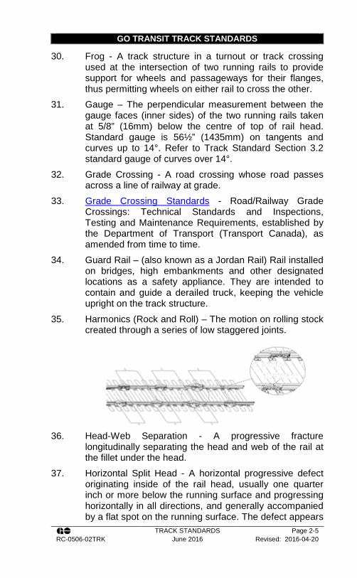
35. Harmonics (Rock and Roll) – The motion on rolling stock created through a series of low staggered joints.
36. Head-Web Separation - A progressive fracture
longitudinally separating the head and web of the rail at the fillet under the head.
37. Horizontal Split Head - A horizontal progressive defect originating inside of the rail head, usually one quarter inch or more below the running surface and progressing horizontally in all directions, and generally accompanied by a flat spot on the running surface. The defect appears

GO TRANSIT TRACK STANDARDS
TRACK STANDARDS Page 2-6 RC-0506-02TRK June 2016 Revised: 2016-04-20
as a crack lengthwise of the rail when it reaches the side of the rail head.
38. Insulated Joint - A rail joint in which electrical insulation is provided to stop electrical current from flowing from one rail to another, separating sections of track into distinct circuits for signal shunting and operation of signal system and crossing protection.
39. IRIS – Integrated Rail Inspection System – A GO Transit heavy truck outfitted with equipment having the capability to test track geometry under loaded conditions, rail wear, and rail flaw testing.
40. Jordan Rail – see guard rail. 41. Localised Surface Collapse - A flattening down and
widening of the rail head other than at the end of a rail, not associated with any internal defect in the rail.
42. Loss of Vertical Height – is the reduction in total height of the rail compared to the nominal rail section. It will be measured at the centre of the head of rail.
43. Match Marks - Marks placed on the web, base and tie plate, used when distressing rail to ensure that rail has moved the required amount.
44. MGT (Million Gross Tons) – The total weight that travels over a section of track.
45. Mill Defect - Deformations, cavities, laps, seams, scabs, burnt steel, or foreign material found in any portion of the rail.
46. Ordinary Break - a partial or complete break in which there is no sign of a fissure, and in which none of the other defects described in this paragraph are found.
47. Out-of-face Surfacing – The continuous raising of track to restore track surface, cross-level, and alignment.
48. No Test Rail (NTR) is rail that the rail flaw detector car is unable to test for whatever reason.
49. New Rail – is rail that has never been in service 50. Partial Worn rail (PW) – (occasionally known as second
hand rail - SH) is rail that has been in service and removed for any cause

GO TRANSIT TRACK STANDARDS
TRACK STANDARDS Page 2-7 RC-0506-02TRK June 2016 Revised: 2016-04-20
51. Piped Rail - a vertical split in a rail, usually in the web due to failure of the shrinkage cavity in the ingot to unite in rolling.
52. Preferred Rail Laying Temperature (PRLT) – The target installation temperature of welded rail in a particular area.
53. Preferred Rail Laying Temperature Range (PRLTR) – The tolerance or range for the PRLT.
54. Rail Flaw Testing – (Also known as Sperry testing, or ultrasonic rail testing) Is a non-destructive method of testing the internal structure of rail through the use of high-frequency sound waves.
55. Rail Joint – A location where two rail ends meet and are connected with a joint bar, or other means. Jointed rail shall be laid with staggered joints. The stagger between joints of opposite rails should not be less than 12ft (3.7 m).
56. Rail Laying Temperature (RLT) – The actual temperature at which the CWR is installed.
57. Railway – GO Transit. A company (CN, CP and TTR) that operates and/or dispatches trains within their corresponding right-of-way.
58. Reference Marks - Marks placed on the web or base of the rail distant from each other that are to be used to check for rail movement and whether rail was added or removed from track.
59. Restraining Rail - Rail installed within special track-work, contacted by the back of wheels to provide additional guidance. Jordan rails may be modified running rails, or a special cross-section. Jordan rails are secured to the running rail using rigid or adjustable separator blocks. In some special track-work a special U33 section, guard rail projecting above the top of the running rail, may be used. These are also used on the Pearson Sub in high degree curves.
60. Restricted Crossing - Is any crossing that is not included in the definition of an Unrestricted Crossing.
61. Running Rail – Rail carrying all vertical loads of railway vehicles and equipment.

GO TRANSIT TRACK STANDARDS
TRACK STANDARDS Page 2-8 RC-0506-02TRK June 2016 Revised: 2016-04-20
62. Runoff – When surfacing track, or when surfacing to a fixed structure, Runoff is the elevation difference in the track structure over a 31 ft. (9.5 m) section.
63. Shelly Rail – A progressive horizontal separation that
may crack out at any level on the gauge side, generally at the upper gauge corner. It extends longitudinally not as a true horizontal or vertical crack, but at an angle related to the amount of rail wear.
64. Special Track Work - A general term used to describe all track hardware that is not standard tie-and-ballast track. Special Track-work includes, turnouts of all sizes, single and double slip switches, expansion joints (sliding rail joints), and crossings (diamonds).
65. Sperry Test – see rail flaw testing 66. Split Web – a lengthwise crack along the side of the web
and extending into or through it 67. Spot Surfacing – Restoring of the track surface, cross-
level and alignment through short stretches of track, not more than 19 ft. 6in (6 m) in length, when a continuous raise is not necessary
68. Superelevation – The amount by which the outer rail of a curve is banked above the inner rail.
69. Surface – The vertical alignment or the surface uniformity in the vertical plane. The measurement for SURFACE shall be the maximum positive or negative mid-ordinate, in inches, of a 62 ft. (18.9 m) chord measured along the top surface of the rail.
GO TRANSIT TRACK STANDARDS
TRACK STANDARDS Page 2-9 RC-0506-02TRK June 2016 Revised: 2016-04-20
70. Temperature a. Ambient Temperature – the air temperature as
measured by a thermometer, not directly exposed to sunlight.
b. Rail Temperature – The temperature of the rail. Rail temperature in cold weather is typically equal to the ambient temperature. As a guideline, in hot weather, the rail temperature is equivalent to the ambient temperature plus 30ºF (16ºC). i. Note: Rail temperature must be
physically measured periodically throughout the day with an approved accurate thermometer. Measurements shall be taken away from all sources of natural and artificial heat and cold including but not limited to the sun, wind, rain, etc.
71. Thermite Weld - A process of welding the ends of two rails together by pouring molten steel between the rail ends causing fusion.
72. Track Buckling – The lateral misalignment of the track structure due to excessive compressive forces in the rail.
73. Transverse Defect - Any progressive fracture occurring in the head of the rail and has a transverse separation.
74. Turnout - A track structure by means of which vehicles are diverted from one track to another. It consists of; a switch, switch machine or switch stand, switch connecting rods, closure rails, stock rails, guard rails, frog, switch ties, and all other special hardware associated with the turnout.
75. Turnout Inspections a. Routine Inspection – A visual inspection to
access the general turnout condition and to identify any defects. This inspection is done each time the turnout is traversed.
b. Walking Inspection – An inspection performed on foot to assess the general condition of a Turnout or other special track work. This
GO TRANSIT TRACK STANDARDS
TRACK STANDARDS Page 2-10 RC-0506-02TRK June 2016 Revised: 2016-04-20
condition is checked against a set checklist, approved by the Railway, and includes gauge and clearances between switch point and stock rails, and the recording of exceptions and remedial actions taken
c. Detailed Inspection – A thorough and detailed inspection performed on foot to assess the condition of all components in each turnout or other special track work. Hand operated switches are to be operated to all positions during this inspection. This type of inspection is further defined in Track Standard 0 Turnout Inspection
76. Ultrasonic Rail Testing – see Rail Flaw Testing 77. Unrestricted Crossing - A public grade crossing or a
grade crossing whose road is one of the following: a. A recreation road or trail or a pedestrian or
bicycle path maintained by a club, association or other organization, including a snowmobile or hiking trail;
b. A road or a pedestrian or bicycle path of a commercial or industrial establishment, including a business operated from a residential or farm property, that is used in connection with the establishment by persons other than employees of the establishment;
c. A road that serves three or more principal residences;
d. A road that serves three or more seasonal residences access to which is not controlled by a gate equipped with a lock;
e. A road that connects two public roads; or f. A road maintained by a resource company, such
as a company involved in forestry or mining activities;
78. Vertical Split Head - a vertical split, through or near the middle of the head, and extending into or through it. A crack or rust streak may show under the head close to the web or pieces may split off the side of the head.

GO TRANSIT TRACK STANDARDS
TRACK STANDARDS Page 3-11 RC-0506-02TRK June 2016 Revised: 2016-04-20
Section 3 - Rail
3.1. General Requirements
1. Where unloaded rail presents a walking hazard it shall be covered by a General Bulletin Order (GBO).
2. Recommended Method 3700-3 - Unloading Rail covers the procedures to be followed when unloading CWR from a rail train. Metrolinx and GO Transit requires a written procedure for unloading CWR from a rail train prior to commencement of work.
3. The owner of the equipment and the operator are responsible for ensuring that all rail unloading equipment and hardware is in good working condition.
4. Rails kept for spot renewals should have the wear measurements, length, and Ultrasonically Tested (UTT) / Ultrasonically Certified (UTC) (where applicable) clearly marked.
5. Rails used for spot renewals should be selected to have the same average wear and metallurgy as the rail in track.
6. Scrap rails must be clearly marked with an X of red paint at regular intervals to differentiate them from reusable rails.
7. Scrap rail less than 4ft in length must be immediately removed from the railway Right-of-Way.
8. Rails used in main track tangents must not be less than 12 ft. (3.7 m) long. Rails used in main track curves should not be less than 19 ft. 6 in (6 m).
9. When removing rail defects by replacing with a plug rail, the following 3 conditions must be adhered to on main tracks containing CWR with an annual tonnage of 40 MGT or greater: a. Must be UTT tested.
i. If not, a class 2 speed restriction must be placed until it has been tested.

GO TRANSIT TRACK STANDARDS
TRACK STANDARDS Page 3-12 RC-0506-02TRK June 2016 Revised: 2016-04-20
b. Gauge face and head wear must be within the limits prescribed in the Transport Canada Track Safety Rules and Appendix F – Rail Wear Limits Table 1 and Table 2 whichever is more restrictive.
c. Type of rail must match the parent rail. For example, if the replacement is in a curve and the parent rail is head-hardened rail, then the plug rail must also be head-hardened.
d. Types of rail are: i. Standard carbon (referred to as 3HB or
300 Brinell hardness). ii. Intermediate hardness. iii. Head-hardened. iv. Note: Type of rail does not apply to
insulated glued joints. e. If the correct type of rail is unavailable, item c of
the above standards shall be modified as follows: i. A plug rail of a different type may be
installed on a temporary basis. This temporary plug rail must not be welded into track.
ii. The temporary plug rail must be removed within 180 days (6 months) of installation and replaced with a plug rail meeting the condition criteria of a, b and c above.
10. When cutting rail the saw cut must be made at least 4 inches from any torch mark or bond/bolt hole in the rail except as identified in 1.6.7.
11. Rail having cuts or holes made with an oxy-acetylene torch, an electric arc, or thermal methods must not be used in track unless being cropped for use per Track Standard Section 7-1.
12. Rail should be unloaded by use of a crane with magnets, rail tongs, skids or threader and must not be dropped.

GO TRANSIT TRACK STANDARDS
TRACK STANDARDS Page 3-13 RC-0506-02TRK June 2016 Revised: 2016-04-20
13. Rail must not be struck with a spike maul, steel hammer or similar tool.
14. All holes newly drilled in rail must be deburred. 15. Rail for replacements and relay programs will be in
accordance with Appendix N – Rail Usage Guidelines. 16. Recommended Method 1303-0 – Classification of Rail
covers the criteria used in the classification and usage of rail that will be either welded into CWR or remain as jointed rail. This can be found at the end of this section.
17. Dragging rail along the track is prohibited unless ALL of the following conditions are met and permission is obtained from the Rail Corridors Senior Manager of Track and Structures: a. A thorough job briefing and field level
assessment is conducted; b. Have readily available a list of phone number for
fire-fighting agencies; c. Any open deck bridges will be wetted down prior
to making the move; d. At least two employees will remain on site to
monitor the site until they are certain there is no fire risk*;
e. The employees are equipped with water and fire extinguisher foam;
f. The employees have a means of radio or cell phone communication;
g. The rail is not dragged faster than 3mph; and h. Steel on steel contact shall be avoided while
dragging. i. Note: it is permissible to place rail on an open
deck bridge for the purposes of installation provided the above is adhered to.
j. * In areas where the rail is to be dragged over more than one bridge and the bridges are in close proximity, the two employees can be used to patrol the area.

GO TRANSIT TRACK STANDARDS
TRACK STANDARDS Page 3-14 RC-0506-02TRK June 2016 Revised: 2016-04-20
3.2. Laying Rail
1. Rail of different metallurgies shall not be mixed in any given stretch of track
2. The gauge of track after laying must be uniform. Rail must be laid to the gauge shown in Section 3.Table 1.
3. Any curve to be designed or constructed greater than 8 degrees must be approved in writing by the Rail Corridors Senior Manager of Track and Structures. The Senior Manager will review that the proposed curve design can be safely negotiated by the fleet of rail cars.
Table 1 – Gauge for High Degree Curves
Degree of Curve Gauge in inches
Gauge in mm
Up to 14°00’ 56-1/2 1435 14°01’ to 16°00’ 56-5/8 1438 16°01’ to 18°00” 56-3/4 1441 18°01’ to 20°00’ 56-7/8 1445
20°01’ to 22°00’ * 57 1448 22°01’ to 24°00’ *† 57-1/8 1451 24°01’ and over *† 57-1/4 1454
* All curves over 20 degrees also require review by external stakeholders that have running rights on GO Transit / Metrolinx territory. † GO Transit bi-level coaches specify a min. horizontal radius of 250 ft. (76.2 m) equivalent to a 23° curve.
4. Any curve approved to be constructed greater than 8 degrees must: a. Identify train handling requirements; b. Reduce train operating speed as required; c. Use MSR type plates; d. Be fully spike and lagged;

GO TRANSIT TRACK STANDARDS
TRACK STANDARDS Page 3-15 RC-0506-02TRK June 2016 Revised: 2016-04-20
e. Use concrete ties or 9 ft. (2.75 m) Grade #1 creosote treated hardwood ties that are 100% end plate, spaced at 18 in (457 mm); on centre,
5. In order to maintain correct gauge, at least every fourth tie must be gauged on tangents and every third in curves greater than 2º. Where poor tie conditions exist, additional gauging may be required.
6. On completion of the rail laying, cribs must be filled and the track must be surfaced and lined, as soon as possible.
7. Jointed rail shall be laid with staggered joints. The stagger between joints of opposite rails should not be less than 12ft (3.7 m).
8. The rail temperature shall be measured periodically throughout the day with an approved accurate thermometer. Measurements shall be taken away from all sources of natural and artificial heat and cold including but not limited to the sun, wind, rain, etc.
9. Expansion space between rail ends, when laying bolted rail or track panels, must be provided. Expansion space of the proper dimension between rail ends can be obtained through the use of shims of the correct thickness as per Table 2 below. Expansion shims must not be removed until the rail is properly spiked, the bolts tightened, and rail anchors applied.
Table 2 - Expansion Gap Required for Rail Temperature
Expansion Gap 33 ft. (10.1 m) Rail Temp.
(ºF) (ºC)
5/16” (8mm) Below 10 Below -12
1⁄4” (6.5mm) 10 to 14 -12 to -10
3/16” (4.8mm) 15 to 34 -10 to 1
1/8” (3.2mm) 35 to 59 1 to 15
1/16” (1.6mm) 60 to 85 15 to 30
0 Above 85 Above 30

GO TRANSIT TRACK STANDARDS
TRACK STANDARDS Page 3-16 RC-0506-02TRK June 2016 Revised: 2016-04-20
Expansion Gap 39 ft. (11.9 m) Rail Temp.
(ºF) (ºC)
5/16” (8mm) Below 6 Below -14
1⁄4” (6.5mm) 6 to 25 -14 to -4
3/16” (4.8mm) 26 to 45 -4 to 7
1/8” (3.2mm) 46 to 65 7 to 18
1/16” (1.6mm) 65 to 85 18 to 30
0 Above 85 Above 30
10. Rail joints will not be installed closer than: a. 20 ft. (6.1 m) from the edge of road crossings.
Short welded rails (SWR) should be used wherever possible
b. 20 ft. (6.1 m) to the face of the back-wall of an open deck bridge on the approach side, nor less than 4 ft. (1.22 m) from the face of the back-wall on the bridge side.
11. Joint bars must be applied and the bolts tightened before the rail is spiked. Bolts in rail joints shall be tightened in the following sequence: a. The centre two bolts b. The second bolt from the centre c. The third bolt from the centre, where applicable
12. Tighten track bolts with track wrenches or power wrenches set to the proper torque settings as per Table 3 below. Care must be exercised when tightening bolts to avoid stripping threads.
Table 3 - Torque to be Applied to Rail Joint Track Bolts
Size of Bolt 7/8 1 1-1/8 Torque ft-lb 375 490 705 Torque N-m 508 664 955
GO TRANSIT TRACK STANDARDS
TRACK STANDARDS Page 3-17 RC-0506-02TRK June 2016 Revised: 2016-04-20
13. When the day’s work is completed, all of the rail laid must be bolted and anchored per standard and each plate must have a minimum of two spikes.
14. Rail joints should be slotted to prevent flowed rail and chipped joints.
15. Where different sections of rail are being joined, one of the following methods must be used: a. compromise rails of the correct sections b. compromise welds c. compromise joints of the correct design
16. When newly laid rail joins rail previously in track, the old rail should be built up by welding at the joint, if necessary, to protect the end of the newly laid rail.
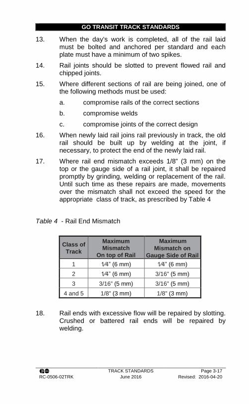
17. Where rail end mismatch exceeds 1/8” (3 mm) on the top or the gauge side of a rail joint, it shall be repaired promptly by grinding, welding or replacement of the rail. Until such time as these repairs are made, movements over the mismatch shall not exceed the speed for the appropriate class of track, as prescribed by Table 4
Table 4 - Rail End Mismatch
Class of Track
Maximum Mismatch
On top of Rail
Maximum Mismatch on
Gauge Side of Rail 1 1⁄4” (6 mm) 1⁄4” (6 mm) 2 1⁄4” (6 mm) 3/16” (5 mm) 3 3/16” (5 mm) 3/16” (5 mm)
4 and 5 1/8” (3 mm) 1/8” (3 mm)
18. Rail ends with excessive flow will be repaired by slotting. Crushed or battered rail ends will be repaired by welding.
GO TRANSIT TRACK STANDARDS
TRACK STANDARDS Page 3-18 RC-0506-02TRK June 2016 Revised: 2016-04-20
3.3. Rail Wear
1. Rail on curves that are approaching their rail wear limits must be monitored frequently and noted on inspection documents. Walking inspections must be conducted on a weekly basis.
2. Rail should not be transposed in main track with annual tonnage greater than 5 MGT. In locations where it has been deemed acceptable, the high rail may be transposed to the low side. In no case will the low rail be transposed to the high side.
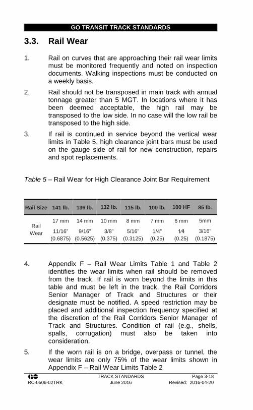
3. If rail is continued in service beyond the vertical wear limits in Table 5, high clearance joint bars must be used on the gauge side of rail for new construction, repairs and spot replacements.
Table 5 – Rail Wear for High Clearance Joint Bar Requirement
Rail Size 141 lb. 136 lb. 132 lb. 115 lb. 100 lb. 100 HF 85 lb.
Rail Wear
17 mm 14 mm 10 mm 8 mm 7 mm 6 mm 5mm
11/16” (0.6875)
9/16” (0.5625)
3/8” (0.375)
5/16” (0.3125)
1/4” (0.25)
1⁄4 (0.25)
3/16” (0.1875)
4. Appendix F – Rail Wear Limits Table 1 and Table 2 identifies the wear limits when rail should be removed from the track. If rail is worn beyond the limits in this table and must be left in the track, the Rail Corridors Senior Manager of Track and Structures or their designate must be notified. A speed restriction may be placed and additional inspection frequency specified at the discretion of the Rail Corridors Senior Manager of Track and Structures. Condition of rail (e.g., shells, spalls, corrugation) must also be taken into consideration.
5. If the worn rail is on a bridge, overpass or tunnel, the wear limits are only 75% of the wear limits shown in Appendix F – Rail Wear Limits Table 2

GO TRANSIT TRACK STANDARDS
TRACK STANDARDS Page 3-19 RC-0506-02TRK June 2016 Revised: 2016-04-20
6. The underside of the rail head must be physically inspected when either one of the following conditions exists: a. Rail wear is at 75% or greater of the
condemnable limit; or b. Rail head shelling, spalling, or corrugation is
present. 7. Should the Rail Corridors Senior Manager of Track and
Structures decided to leave the worn rail in the track, the speed restriction to be applied shall be as near as possible to the equilibrium speed, not exceeding the maximum allowable speed for that class of track, until the rail can be changed out. If rail change-out cannot happen within 30 days (or 60 days on class 2 track), then a further speed restriction of 10mph must be applied.
8. Where rail wear has resulted in joint bars being impacted by wheel flanges, the joint must be welded or a high clearance bar or compatible worn bar must be applied. Train speed must be restricted to the equilibrium speed.
3.4. Continuous Welded Rail
1. All track forces must properly protect and promptly report any unusual and/or unsafe conditions observed developing in CWR to the Rail Corridors Manager of Track.
2. All supervisory personnel, including the Track Foreman and Track Inspectors on whose territory CWR is laid, must be familiar with the causes, high risk conditions, work and inspection procedures, and slow order requirements to avoid track buckling.
3. All employees responsible for the installation, maintenance and inspection of CWR must be trained and qualified in the maintenance of CWR.
4. The Current PRLT (Preferred Rail Laying Temperature) is outlined in Table 6.

GO TRANSIT TRACK STANDARDS
TRACK STANDARDS Page 3-20 RC-0506-02TRK June 2016 Revised: 2016-04-20
Table 6 - Preferred Rail Laying Temperature
GO Transit
100 ºF
(37.7 ºC)
5. The PRLTR (Preferred Rail Laying Temperature Range)
is the PRLT +15 ºF/ -10 ºF (+8.3 ºC/ -5.5 ºC). 6. CWR will be installed and anchored within the PRLTR
without further adjustment. CWR installed outside the PRLTR must be destressed as soon as possible after laying. Destressing must be completed before the rail temperature increase is greater than 40 ºF (22 ºC) above the RLT.
7. CWR must be destressed using proper procedures. Heaters or expanders must be used to bring the rail to the correct length. The CWR Thermal Expansion Chart is contained in Appendix J – Continuous Welded Rail Thermal Expansion Chart
8. CWR will not end on open deck bridges or closer than 200 feet (61 m) from the back-wall of the bridge.
9. A list of the rail temperatures marked on each string, the string numbers, alloy (if any) mileage and date of laying or adjusting shall be compiled and kept up to date by the Track Supervisor with copies to the GO Transit Rail Corridors Manager of Track. The actual rail laying temperature will be marked at the end of each string of CWR installed.
10. Use six-hole joint bars with at least four bolts installed on standard joints that are planned to be eliminated through field welding. To facilitate welding, the hole nearest the end of the two abutting rails must not be drilled. A joint gap not exceeding 3/8 in. (9.5 mm) is to be left. All temporary joints must be welded prior to the onset of winter. Any temporary joints that are unable to be welded prior to winter should be fully drilled, bolted and box anchored for 200ft (61 m) in both directions.

GO TRANSIT TRACK STANDARDS
TRACK STANDARDS Page 3-21 RC-0506-02TRK June 2016 Revised: 2016-04-20
11. Trains may operate over unanchored track at a speed not exceeding 10 mph under authorization from the Foreman. Such authorization should include instructions to avoid unnecessary brake applications through or near the work area.
12. On completion of the day’s work, all rail laid, or ties inserted, must be spiked with a minimum of two rail holding spikes per plate, bolted and anchored per standard. The gang must then return to spike the ties to the applicable spiking pattern in Appendix P – Spiking Patterns
13. The Rail Corridors Manager of Track or his designate will make a decision on whether or not to adze ties and will record this information in the resulting contract.
14. CWR strings may be left between the rails until the next shift (overnight) provided that: a. The CWR string height does not exceed 1 in
(25 mm) above the top of the running rail b. Deflectors are placed at each end of rail c. The CWR rail ends are bypassed and secured
at the ends with spikes.
3.5. Maintenance of Thermal Stress in Rail
1. Detailed guidelines on destressing CWR are contained in Recommended Method 3205-0: Destressing CWR, Recommended Method 3205-2A: Destressing at Turnouts, and Recommended Method 3205-2B: Destressing at Roadway Crossings. Guidelines on handling rail failures in CWR are contained in Track Standard Section 3.7.
2. Precautions must be taken to monitor the length of rail installed during rail changes and repairs. Whenever practicable, rail will not be added to CWR track.
3. When a rail is to be changed, reference marks will be made on the web of the rail extending onto the rail base prior to cutting the CWR. They will be on each side of the location where the cut is to be made and where the

GO TRANSIT TRACK STANDARDS
TRACK STANDARDS Page 3-22 RC-0506-02TRK June 2016 Revised: 2016-04-20
mark will not be covered by joint bars or removed by changing the rail.
4. The reference marks and the measured distance between them will be written with paint stick or other permanent marker.
5. When addressing a failure in CWR: a. If the rail ends have pulled apart, the distance of
separation of the two rail ends will be noted. The distance recorded on the rail shall then be the measured distance between the reference marks minus the separation of the rail ends.
b. If the rail ends bypass each other, the distance recorded on the rail shall be the measured distance between the reference marks plus the amount the rail ends bypass.
c. After the rail has been changed, measure the distance between the reference marks. If the distance changes over the original measured distance, the amount of rail added or removed will be marked on the rail and the information will be forwarded to the Track Supervisor.
6. The Track Supervisor will be responsible for the locations and amounts of rail that is added or removed.
7. Continuous welded rail must be maintained so that it is in a state of zero thermal stress in between the PRLTR. a. Continuous welded rail may drift into tension or
compression, so that it is stress free at some temperature outside the preferred rail laying temperature range, as a result of such activities as track surfacing, tie renewals, ballast cleaning, track lining, and curve rail renewal. Even if the track is not worked on, the rail can shift and go out of destress as a result of rail breaks, emergency brake applications, worn or defective anchors, poor quality or insufficient ballast, Permanent Slow Order locations, or soft subgrade. On hills, rail is generally seen to move slowly downhill, resulting in an excessively low stress-free temperature at the bottom and an

GO TRANSIT TRACK STANDARDS
TRACK STANDARDS Page 3-23 RC-0506-02TRK June 2016 Revised: 2016-04-20
excessively high stress-free temperature at the top.
8. The Rail Corridors Manager of Track will ensure that any locations with rail added during cooler weather will have the correct length plug installed prior to the ambient temperature reaching 70ºF (21ºC). When ambient temperatures exceed these, and more than 1 inch (25 mm) of rail within 1,000 feet (304.8 m) has been added, and adjustments have not been made, then a speed restriction will be placed.
9. Except in the case of emergencies, no surfacing and lining, rail replacement or tie renewal will be performed if the rail temperature is above the PRLT unless approved by the Rail Corridors Senior Manager of Track and Structures or designate.
10. Track Maintenance activities that disturbs track and could potentially cause a track buckle must be protected by the appropriate speed restriction. The tables in Appendix I – Speed Restrictions for Track Work contain the speed restriction and the appropriate timeframe for removing them on CWR track.
11. Refer to Track Standard section14.16 and 14.17 for hot weather related inspections and speed restrictions.
3.6. Destressing Rail
1. When destressing, the adjusting temperature is to be marked on the rail and all previous temperature markings shall be obliterated.
2. When it is evident that the stress free temperature of a section of rail has decreased to a level that a track buckle may occur, the stress-free temperature should be adjusted back to the Preferred Rail Laying Temperature. The method of destressing involves removing rail anchors, cutting the rail and removing rail to achieve the correct rail laying temperature.
3. Prior to cutting the rail, match marks MUST be made on the base of the rail extending onto the tie plates about every 100 ft. (30 m) where anchors are removed to ensure that the rail moves all through the limits.

GO TRANSIT TRACK STANDARDS
TRACK STANDARDS Page 3-24 RC-0506-02TRK June 2016 Revised: 2016-04-20
4. Where long stretches are being destressed, make marks every 200 feet (61 m). Make reference marks near the cut, measure the distance between them and write this number on the rail. The rail will be cut, ends either trimmed or offset and anchors will be removed 200 feet (61 m) from each side of the cut and the rail allowed to move freely. At this state the current temperature is now the Stress Free Temperature and Rail Laying Temperature at this location and it must be clearly marked on the web of the rail along with the date and the gang ID.
5. The following preparatory work MUST be performed: a. Measure the length of rail to be destressed,
determine and mark locations where rail is to be cut.
b. Make match marks on the base of rail and tie plates or concrete ties on unanchored ties just beyond the location where cut is to be made, and at intervals throughout the length to be destressed.
c. Rail anchors may have to be tightened for at least 200 feet (61 m) on each side of where the rail is to be cut.
d. All ties must be fully box anchored at least 200 feet (61 m) beyond the rail being destressed prior to making the cut.
e. In concrete tie territory distribute chording clips and tie pads, insulators and risers if required.
6. The rail may need to be cut and placed in a position that will permit the rail ends to bypass each other.
7. The rail must be raised from the tie plates or tie pads and placed on risers. If power vibrators are used, it is not necessary to place the rail on risers.
8. On wood ties rail anchors must be removed and risers placed every 12 to 15 ties to ensure base of rail is free from tie plates.
9. In concrete tie areas all rail clips and insulators must be removed and chording clips must be installed

GO TRANSIT TRACK STANDARDS
TRACK STANDARDS Page 3-25 RC-0506-02TRK June 2016 Revised: 2016-04-20
approximately every 20 ties on curves up to 4 degrees and every 15 ties on curves 4 degrees and over.
10. Following the completion of items 6 through 9, the rail now in the raised position on risers, or fully power vibrated, is stress free at the present rail temperature as it is totally unrestricted.
11. The base of the rail and tie plate or base of rail and clip shoulders must be match marked with a marking pencil throughout the length of rail to be destressed.
12. Knowing the length of rail being destressed, the PRLT and the present rail temperature, the calculations can now be made as to the adjustment requirement.
13. Check the anchors on the 200 feet of rail that was fully box anchored beyond the rail that was being destressed. If this rail is the last 200 feet of CWR before jointed rail, it will have to be destressed by removing the anchors, putting it in a stress-free state when the ambient temperature is at the PRLT, and reapplying the anchors.
14. The adjustment being realized, the match marks must be checked to ensure that proper movement has been achieved.
15. Remove risers. In wood tie areas, tap down the raised spikes and apply rail anchors. In concrete tie areas, apply insulators and clips. The chording clips are not removed until they are encountered when the clip installation reaches their location.
16. Obliterate any previous rail laying temperatures that may have been painted on web of rail and paint new "destressed" temperature, which should be the PRLT.
17. Destressing reports must be created and forwarded to the Rail Corridors Manager of Track and to the Track Supervisor.
18. No more than 3,000 feet (914 m) of rail may be destressed at any given time; 1,500 feet (457 m) on each side of the destressing point.
19. Destressing should be scheduled and completed when the rail temperature is at or below the preferred rail laying temperature.
GO TRANSIT TRACK STANDARDS
TRACK STANDARDS Page 3-26 RC-0506-02TRK June 2016 Revised: 2016-04-20
20. When the rail temperature is above the PRLT and there are signs of a potential track buckle, the rail must be cut. Record temperature of rail, limits of rail movement, amount of rail cut out, and width of joint gap when bolts and bars applied. Report this information to the Rail Corridors Manager of Track and the Track Supervisor for further instructions.
21. If rail cannot be destressed prior to the ambient temperature reaching 70°F (21°C), then a speed restriction must be applied until such time as the rail is destressed. The speed restriction shall be 30 MPH.

GO TRANSIT RECOMMENDED METHODS
TRACK STANDARDS Page 3-27 RC-0506-02TRK June 2016 Revised: 2016-04-20
Recommended Method 3205-0: Destressing CWR
1. It has been established that if track has good line and surface and a standard ballast section, with anchors properly applied, and the ballast has had time to compact itself after being disturbed, the track structure will withstand a temperature of 50°F above the Preferred Rail Laying Temperature (PRLT).
2. Destressing may be done by means such as: a. atmospheric temperature b. heaters c. hydraulic rail pullers
3. Before destressing any location, the following information must be known:
a. the PRLT b. the length of CWR to be destressed c. the present rail temperature
4. In most instances the following tools, equipment, and material will be required to carry out a destressing program:
a. At least two rail thermometers or a pyrometer b. chording clips c. soapstone or marking pencil d. 120 ton hydraulic rail puller or rail heater e. rail saw f. rail drill g. steel measuring tape at least 50 feet in length, or
rolling measuring wheel h. Thermite welding equipment, with proper kits for rail
weights i. additional bolts, spikes, anchors, tie plugs, Pandrol
clips, pads, insulators j. brass or other soft hammers or a vibrator

GO TRANSIT RECOMMENDED METHODS
TRACK STANDARDS Page 3-28 RC-0506-02TRK June 2016 Revised: 2016-04-20
k. risers (spike, long bolt, pipe, special design tool) l. claw bars m. spike mauls n. sledge hammers o. track jack p. track wrenches and torque wrench q. anchor applicator wrench if required r. rail slotter if welders not available s. one or two pieces of rail of the same weight, section,
metallurgy, and degree of wear as the rail in track, 12 feet long or longer (19’6” or longer on curves 2 degrees and above)
t. rail tongs u. rail positioner / rail seater v. clip applicator
5. Two examples are provided below: Example 1:
Rail anchored hot; rail ends pull apart Length of CWR being destressed
3000ft
PRLT Current rail temperature Degrees temperature below PRLT
100°F 65°F
35°F
(100-65°F)
Rail ends separate leaving a 9 inch gap.
CWR movement charts in Appendix J – Continuous Welded Rail Thermal Expansion Chart shows that rail 25°F below the PRLT should separate leaving a 6 inch gap (since 3000’ is not shown on table, use movement at 1000’ and multiply by 3). However, the rail ends separated away from each other leaving a gap of 9 inches. Therefore, the rail prior to destressing was in a stress free state at a temperature higher than the PRLT.
Adjustment required: 6 inches
Actual Gap: 9 inches
Difference: (6”-9”) 3 inches less rail than required
Two standard welds will add 2 inches steel material

GO TRANSIT RECOMMENDED METHODS
TRACK STANDARDS Page 3-29 RC-0506-02TRK June 2016 Revised: 2016-04-20
Length of rail to be added (3”-2”) 1 inch
When the 1 inch of rail plus the 2 inches of weld steel material is added, the rail would be stress free when the rail temperature is at 90°F.
Procedure: Cut out a piece of rail from the CWR at least 12'0" long and install another piece of rail that is one inch longer. Leave a gap of 1 inch for each weld. The rail now in place can be welded at one end, pulled together and welded at the other end.
An approved wide gap weld may be used where applicable. The Approved Track Welder Manual should be consulted for the proper procedures.
Example 2: Rail anchored cold; rail ends bypass
Length of CWR being destressed PRLT Present rail temperature Degrees temperature below PRLT
3,000 ft. 100°F 65°F
35°F
(100-65°F)
Rail ends bypass 3inches
CWR movement charts in Appendix J – Continuous Welded Rail Thermal Expansion Chart show that rail 25°F below the PRLT should separate leaving a 6 inch gap (since 3000’ is not shown on table, use movement at 1000’ and multiply by 3). However, instead the rail ends by-passed each other by 3 inches. Therefore, prior to destressing, the rail was in a stress free state at a temperature lower than 65°F.
Adjustment required: 6 inches
Actual Bypass: 3 inches
Difference: (6”+3”) 9 inches more rail than required
One standard weld will add 1 inch steel material
Length of rail to be cut off (9”+1”) 10 inches
10 inches of rail will be cut off leaving a 7 inch gap. The rail is then to be pulled back 6 inches and welded.
This rail would now be stress free when the rail temperature is 100°F.(PRLT)
GO TRANSIT TRACK STANDARDS
TRACK STANDARDS Page 3-30 RC-0506-02TRK June 2016 Revised: 2016-04-20
3.7. Failures in CWR
1. Service failures of CWR include broken rails, pull-aparts, buckles or other rail damage. Any service failure and the associated remedial action must be reported promptly to the Rail Corridors Manager of Track or designate.
2. Joints in CWR will be treated as follows: a. Temporary joints in CWR that cannot be
immediately welded will be drilled and splice bars applied to allow for future thermite welding, leaving a joint gap not exceeding 3/8 in. (9.5 mm). Only the outer four holes are to be drilled and used. All temporary joints should be welded prior to the onset of winter. Any temporary joints that are unable to be welded prior to winter should be fully drilled, bolted and box anchored.
b. Permanent joints in CWR which are not intended to be welded will be fully drilled and bolted, splice bars applied, and the rail fully box anchored 200 feet (61 m) each side of the joint.
3. Three types of failures can be detected in CWR: a. Visually detected failures b. Ultrasonically detected failures c. Signal Detected Failures
4. Immediate repairs are required for the following: a. Certain rail defects, weld defects, and breaks as
per Appendix H – Remedial Action For Rail Defects
b. Pull-aparts c. Track buckles d. It is essential that any type of failure receives
prompt attention and action to maintain safe movement of traffic.
5. Prior to cutting rail, reference marks should always be made on the web of the rail. The marks should be on
GO TRANSIT TRACK STANDARDS
TRACK STANDARDS Page 3-31 RC-0506-02TRK June 2016 Revised: 2016-04-20
either side of the proposed cut and should be of sufficient distance apart so as not to be obscured by joint bars. The distance between the marks shall be measured and noted on the rail prior to the cut being made. This will create a reference to confirm whether any rail was added or removed during the repair
6. Dye penetrant testing shall be performed on rail ends: a. in the event of an in-service rail failure; b. when a defect is visually detected; or c. when one of the following defects was not
immediately removed from track after detection by an ultrasonic test car: i. Vertical Split Head ii. Horizontal Split Head iii. Head Web Separation iv. Split Web v. Piped Rail
7. Note that it is possible for vertical split heads to carry through plant and field welds.
8. See Track Standard Section 3.12 for further details.
3.8. Repairing Pull-Aparts
1. When a pull-apart occurs corrective action must be taken by either applying heat or expanders to bring the rail ends together or by installing a temporary closure rail.
2. Do NOT use heat ropes for heating rail on open deck bridges.
3. Make the repair with the use of a rail puller, or heat the rail to close the gap.
4. Install new bolts to proper torque. See Track Standard Section 3.2.12.Table 3
5. If possible, adjust the anchors for at least two hundred feet. Within 30 days the joint must be welded, or all 6

GO TRANSIT TRACK STANDARDS
TRACK STANDARDS Page 3-32 RC-0506-02TRK June 2016 Revised: 2016-04-20
bolts installed, or location anchored 200 ft. in either direction.
6. When the rail temperature is at or near the preferred rail-laying temperature, the location must be checked to see if destressing is required
7. Ensure proper joint maintenance is performed and anchor condition and pattern conforms to this Track Standard.
8. If the pull-apart is greater than 3” (76mm), a temporary repair should be made by cutting out sufficient rail to allow a minimum twelve foot rail or 19’6” on curves, to be installed.
9. Arrangements should be made to have the closure rail welded in before the rail ends batter. Depending on traffic levels, excessive batter may occur in as little as two weeks.
10. A minimum of one inch (25 mm) must be removed from the closure rail for each thermite weld at the time of welding.
11. Always record the amount of steel added. This information is necessary for making the permanent repair, which should be completed as soon as possible
12. The cause of the pull-apart must be determined, and forwarded to the Rail Corridors Manager of Track. Possible causes include: a. Insufficient crib and shoulder ballast b. Insufficient, improperly adjusted or defective rail
anchors c. Rail anchored above the preferred rail laying
temperature range and not destressed d. Unstable road bed e. Maintenance work performed with the rail
temperature above the PRLTR f. Excessive tension due to extreme cold or a
sudden drop in temperature g. Shearing the joint bolts (i.e. by dragging
equipment)

GO TRANSIT TRACK STANDARDS
TRACK STANDARDS Page 3-33 RC-0506-02TRK June 2016 Revised: 2016-04-20
h. Ballast surfacing work being performed when the rail temperature is high causing such things as curves to be lined outward
i. Emergency application of train brakes
3.9. Repairing a Track Buckle
1. Whenever ambient temperature exceeds 30ºC (86ºF) or during periods of significant seasonal increase in temperature (i.e. Spring), hot weather track patrols are required. Refer to Track Standard Section Extreme Hot Weather Inspections14.16.
2. When a track buckle occurs one of the following corrective actions must be taken: a. Make cuts in the CWR near the buckle, remove
rail anchors 225 ft. (69 m) on either side of the buckle allowing rail to run, line the track and make a closure.
b. Place the track in the best possible alignment where it will remain without further movement and where it will provide proper clearance.
c. While under temporary repair, trains are to be operated at a speed specified by the foreman in charge but not exceeding than 10 mph (16km/h)
d. After the track is fully repaired, it will be treated as disturbed track and protected by the appropriate speed restriction indicated in the tables in Appendix I – Speed Restrictions for Track Work, depending upon the rail temperature.
e. Permanent repairs may include applying new anchors, adding ballast to shoulders and cribs, replacing defective ties, tamp, line, surface track, and stabilize, cut out rail, destress, and weld.
3. In the event that a track buckle was repaired by lining without cutting the rail, and the track was lined exceeding one inch for one third of the length of the

GO TRANSIT TRACK STANDARDS
TRACK STANDARDS Page 3-34 RC-0506-02TRK June 2016 Revised: 2016-04-20
curve or more, a temporary slow order must be placed as per Table 7.
Table 7 Minimum Speed Restrictions for Repairs to Buckled Track by Lining without Cutting the Rail
Expected Rail Temperature
Stabilizer Available TSO Requirement
Below PRLT Yes 12 GO Trains at 30mph No 73 GO Trains at 30mph
Above PRLT
Yes 24 GO Trains at 30mph
No
24 GO Trains at 10mph and inspect; if ok, 73 GO Trains at 30mph;
Then 73 GO Trains at 40mph and inspect;
Refer to Appendix I – Speed Restrictions for Track Work for other equipment tonnage. 4. When a track buckle occurs, and the rail temperature is
within or below the PRLTR, check that the ballast section is as shown on Standard Plan CN Standard Plan TS-2205, and anchor condition and pattern conforms to the Track Standards. If the track can be realigned where it will remain without further movement and where it will provide clearance on double track, rock cuts, platforms etc. this may be done. Restore standard ballast section and adjust rail anchors. Otherwise the rail must be cut or joint dismantled and placed in a position that will permit the rail ends to bypass each other (see Track Standard Section 3.6 )Realign the track to its former position, and make temporary repair by cutting out any rail necessary to drill four outer holes and install splice bars and bolts. Record the amount of steel removed. Destressing must be scheduled and completed as soon as the rail temperature is at or below the preferred rail laying temperature as per Track Standard Section 3.6. A temporary slow order must be placed as per Table 7
5. When a track buckle occurs and the rail temperature is above the PRLTR, place the track in the best possible alignment where it will remain without further movement, and where it will provide clearance on adjacent track, sidings, rock cuts, platforms, etc. In most cases the track

GO TRANSIT TRACK STANDARDS
TRACK STANDARDS Page 3-35 RC-0506-02TRK June 2016 Revised: 2016-04-20
will have to be lined out to the shoulder to relieve the pressure. Ensure standard ballast shoulder section is restored, and place a temporary slow order as per Table 7. As soon as the rail temperature is at or below the preferred rail laying temperature, the track must be lined and placed in its original position, surfaced, shoulder ballast restored, anchors adjusted and checked to see if destressing is required. Place a temporary slow order, as per Table 7. Promptly notify the Track Supervisor and Rail Corridors Senior Manager of Track and Structures of the temperature of the rail at the time of the buckle.
3.10. Track Buckling Causes and Prevention
1. Track Buckling is a constant threat during times of high or rapidly rising temperatures. It is a particular concern on CWR territory in the spring and summer months, generally between the hours of 11:00 and 20:00.
2. Sufficient patrols will be arranged in order to cover the track during these times.
3. Immediate remedial action will be taken by either placing a speed restriction or adjusting the rail when any of the following are apparent: a. Bunched or pushing ties which are plowing
ballast; b. Rail running either through rail anchors or with
the anchors; c. Rail lifting up under the spike heads (rail base
lifted out of seat); d. Rail pushing against both shoulders of the tie
plates; e. Canting rail on curves; f. Short flat misalignments in curves; g. Gaps at the ends of the ties indicating lateral
movement of the track; h. Track having a wavy or kinky alignment; i. Gaps or voids in ballast at the end of ties; j. Tie movement;

GO TRANSIT TRACK STANDARDS
TRACK STANDARDS Page 3-36 RC-0506-02TRK June 2016 Revised: 2016-04-20
k. Churning of ballast caused by tie movement resulting in gauge and line kinks; or
l. Longitudinal movement of switch point in relation to the stock rail.
4. When surfacing near high risk locations Track Standard Section 11-3 must be followed.
5. High risk locations include but are not limited to: a. Curves; b. Bridge approaches; c. Grade crossings; d. Crossings with other railways (diamonds); e. Bottom of a heavy grade, or bottom of a sag; f. Sink holes; g. Rock cuts where rail temperatures may be
extremely high; h. Areas having a history of lateral instability; i. Recently disturbed track (e.g. tie replacements,
surfacing, etc.); j. Locations where track work was undertaken in
cold weather and rail has not been destressed, rail anchors not applied, or ballast not restored;
k. Locations where rail was recently welded; l. Previous track buckle not permanently repaired; m. Track where pull-aparts or broken rails have
occurred during cold weather and it was necessary to add rail to close the gap; and/or
n. Fixed locations such as turnouts, crossings, and bridges, transition from wood to concrete ties. In particular, pay special attention to locations where rail has been observed to be moving through a rail anchor towards a fixed location.
6. Before surfacing and lining a curve on main tracks, the curve must be staked if the degree of curvatures is greater than 3° and the rail temperature is greater than 50°F (28°C) below the Preferred Rail Laying
GO TRANSIT TRACK STANDARDS
TRACK STANDARDS Page 3-37 RC-0506-02TRK June 2016 Revised: 2016-04-20
Temperature, or large temperature variations are expected within the next 24 hours.
7. To stake a curve prior to surfacing and lining, place at least 3 reference stakes uniformly spaced around the curve with the middle stake located near the middle of the curve. Additional stakes may be used due to the overall length of the curve.
8. Inspect for curve movement periodically after the work, especially during periods of large temperature fluctuations. If the curve is found to have shifted inward more than 1”, it must be lined out or destressed prior to ambient temperature reaching 70°F (21°C). If the curve is not lined out or destressed, then a speed restriction must be placed per Track Standard Section 3.6.21. The effective rail length added to a curve as a result of chording inwards is calculated in Appendix B.
3.11. Remedial Action for Broken Rail or Defect
1. The track or signal maintainer that arrives to the location of a broken rail first, must inspect the track for 300 ft. (91 m) in both directions from the break. The maintainer should be looking for pieces of equipment and for damage to the rail or track structure (e.g. wheel marks).
2. The location of the rail break and findings from the above inspection must be communication to the Rail Corridors Manager of Track. A report must be submitted through the Rail Corridors document management system.
3. Each defective rail must be marked with a highly visible yellow paint marking on both sides of the web and base when possible.
4. When removing rail defects from track, careful examination of the adjacent rail ends of the parent rail must be performed to ensure that the defect has been completely removed.
5. Two 6 inch (150mm) sections, each including the broken portion shall be submitted to the Rail Corridors Manager of Track within 48 hours of the incident for metallurgical

GO TRANSIT TRACK STANDARDS
TRACK STANDARDS Page 3-38 RC-0506-02TRK June 2016 Revised: 2016-04-20
testing. The ends of the rails with the broken portion must be wiped with oil to prevent corrosion.
6. The remedial action to be taken is dependent on the rail temperature at the time of the repair.
7. When the rail temperature is at or near the PRLT: a. If no adjustment of the rail is required it may be
possible to cut out a defective weld and make a permanent repair by installing a wide gap field weld, where applicable. Proper procedures can be found in the CN Track Welder Manual.
b. If adjustment to rail is required and thermite welds can be made at the time of repair, cut out at least 12’-2” (3.7m) for tangent or 19’-8” (6m) for curves including the defect. Install a permanent closure rail two inches shorter than the rail cut out to account for the two welds required. All permanent closure rails are required to be the same metallurgy and approximate wear as the rail removed.
c. If welds cannot be made at the time of repair, install a closure rail with temporary joints, leaving no gap. Arrangements should be made to have the closure rail welded in before the rail ends batter. Depending on traffic levels, excessive batter may occur in as little as two weeks. One inch of rail , for each thermite weld, must be removed from the closure rail at the time of welding. When a temporary closure rail is to be welded, the reference marks and original measurements noted on the rail should be consulted to ensure the appropriate rail length is being maintained.
d. Always record the amount of steel added. This information is necessary for making the permanent repair, which should be completed as soon as possible.
8. When the rail temperature is below the PRLT: a. If welding is possible at the time of the repair cut
out at least 12’-2” (3.7m) for tangent or 19’-8” (6m) for curves including the defect. Install a
GO TRANSIT TRACK STANDARDS
TRACK STANDARDS Page 3-39 RC-0506-02TRK June 2016 Revised: 2016-04-20
permanent closure rail two inches shorter than the rail cut out to account for the two welds required. Bring together rail ends using hydraulic rail pullers or by heating so as to leave a 1” gap for each weld. All permanent closures are required to be the same metallurgy and approximate wear as the rail removed.
b. If welds cannot be made at the time of repair, install a closure rail with temporary joints.
c. The closure rail is to be the same length as the rail cut out to allow for future welding.
d. The rail ends must be brought together with a hydraulic rail puller or by heating so as to leave no joint gap.
e. Arrangements should be made to have the closure rail welded in before the rail ends batter. Depending on traffic levels, excessive batter may occur in as little as two weeks.
f. One inch of rail, for each thermite weld, must be removed from the closure rail at the time of welding.
g. When a temporary closure rail is to be welded, the reference marks and original measurements noted on the rail should be consulted to ensure the appropriate rail length is being maintained.
h. If it is expected that the joint will be under significant tension (such as prolonged winter exposure or an expected drop in temperature) or if the joint is in a location with a history of pull-aparts, the joint should be installed with all six bolts and be box anchored for 200’ (61m) in either direction.
i. If the rail ends separate more than three inches, a temporary repair should be made by installing a closure rail of a length equal to the opening leaving a gap at each joint no greater than 1/2".
j. Always record the amount of steel added. This information is necessary for making the

GO TRANSIT TRACK STANDARDS
TRACK STANDARDS Page 3-40 RC-0506-02TRK June 2016 Revised: 2016-04-20
permanent repair, which should be completed as soon as possible
9. When the rail temperature is above the PRLTR a. Box anchor every tie in both directions for 200
feet (61 m) start at a point 8 feet (2.4m) on either side of the defect and.
b. A welder using an oxyacetylene torch to cut the rail must make the cut close to the defect and on such an angle as to allow the rail ends to by- pass each other. When torch cutting rail the following guidelines must be followed: i. The rail is preheated prior to cutting; ii. The torch cut is relatively smooth; and iii. Within 30 minutes of torch cutting, the
rail is trimmed with a rail saw at least ¼” and thermite welded.
iv. If any of the items above are not followed, the rail is allowed to cool following a torch cut or if a train has been allowed to pass over the torch cut rail prior to welding, a minimum of 4” (102 mm) of rail must be removed on either side of the torch cut.
c. Temporary repair will be made by cutting out the defect and any torched rail, and installing a plug rail.
d. Drill the four outer holes and install splice bars and bolts leaving no joint gap.
e. Record the amount of steel removed. This information is necessary for making the permanent repair.
10. Extra care must be taken on Direct Fixation Track on structures when a broken rail is found. Destressing MUST occur immediately.
GO TRANSIT TRACK STANDARDS
TRACK STANDARDS Page 3-41 RC-0506-02TRK June 2016 Revised: 2016-04-20
3.12. Defective Rails
1. No Test Rail (NTR) is rail that the rail flaw detector car is unable to test for whatever reason. Rail Flaw code NTR will appear on the list of defects.
2. If an NTR is detected in Class 3 or higher, one of the following actions are required: a. After a second consecutive NTR in the same
location for Class 4 and 5, a Class 3 speed restriction must be placed.
b. After a third consecutive NTR in the same location for Class 3, 4, and 5, a Class 2 speed restriction must be placed.
c. If the NTR is on a major structure (bridge, overpass, or in a tunnel) there must be an immediate one class reduction in speed. A second consecutive NTR in the same location will require a Class 2 speed restriction.
3. To correct a NTR any of the following actions can be taken: a. Hand test or use a walking stick and ensure
proper test performed. b. Take corrective action on the rail to remove the
reason for the NTR, e.g., use grinder to remove corrugation or shelly so the rail flaw detector can perform a good test.
c. Change the rail. d. Reduce speed to Class 2.
4. When a rail in track contains a defect the following procedure should be followed: a. Identify the rail surface condition. Detailed
descriptions of rail surface irregularities can be found in Appendix G – Rail Defect Descriptions
b. Check surface of rail with straightedge for indication of surface collapse or crushed head. The remedial action for these defects can be found in Track Standard Section 3.14.
GO TRANSIT TRACK STANDARDS
TRACK STANDARDS Page 3-42 RC-0506-02TRK June 2016 Revised: 2016-04-20
c. If spalling is present, measure depth of spall with a Spalling Depth Gauge.
d. Visually check underside of rail head for indication of crack-out in the upper fillet area.
e. Apply remedial action from Appendix H – Remedial Action For Rail Defects and notify the Rail Corridors Manager of Track of the defect condition. This remedial action does not apply to incidents of spalls on switch points, frog points, or in rail joint areas. Spalls at these locations are to be welded in accordance with existing approved procedures.
5. Note that whenever the ballast section is frozen, or when the track structure is otherwise stiff, such as on bridge structures or where concrete ties are installed, the development of rail surface irregularities will escalate rapidly.
6. When a rail in track contains any of the defects listed in the Appendix G – Rail Defect Descriptions, operation over the defective rail is not permitted until: a. The rail is replaced; or b. The remedial action prescribed in the applicable
table is initiated. 7. On Class 1, 2, and class 3 track with less than 20 MGT
annually, where no passenger trains operate, all defects must be removed as soon as conditions permit but in no case longer than the next ultrasonic test car run
8. Defective rails and rail breaks must be reported to the GO Transit Track Evaluation Officer and the Rail Corridors Manager of Track.
9. When a defect is found on a Class 1, 2, or Class 3 track carrying less than 20 MGT annually, refer to and apply the appropriate remedial action codes A through I of 24 in Appendix H – Remedial Action For Rail Defects. a. Any Class 3 track carrying passenger trains,
regardless of annual tonnage, refer to and apply the appropriate remedial action codes 1 to 12 of Table 42 in Appendix H – Remedial Action For Rail Defects.

GO TRANSIT TRACK STANDARDS
TRACK STANDARDS Page 3-43 RC-0506-02TRK June 2016 Revised: 2016-04-20
10. Refer to and apply the appropriate remedial action codes 1 to 12 of Table 42 in Appendix H – Remedial Action For Rail Defects, when a defect is found in: a. Class 3 track carrying 20 more; or, b. Class 4 and 5 track.
11. Damaged rail and ordinary breaks will be handled according to appropriate remedial action table.
3.13. Defects at CAD Welds
1. Do NOT perform any new CAD welds on GO Transit Territory.
2. Where defective CAD weld bonds have been detected on the rail head between 0 and 20 per cent, the following repair procedure applies: a. Grind the field side of the rail head, containing
the defect (crack), carefully so as to ensure no overheating of the rail head will occur. Overheating and rapid cooling of the rail may cause the formation of martensite, which is a very hard brittle microstructure easily susceptible to cracking.
b. If more than 1/4 inch (6 mm) needs to be ground, the rail must be removed.
c. The grinding must be tapered over a distance of at least 12 inches (305 mm) on each side of the defect so as to not cause an abrupt change in the rail head section.
d. The defect shall only be considered as removed if ascertained through a follow-up ultrasonic test.
e. If the defect is detected a second time by ultrasonic means, then the defect must be protected as per Appendix H – Remedial Action For Rail Defects and removed from track.
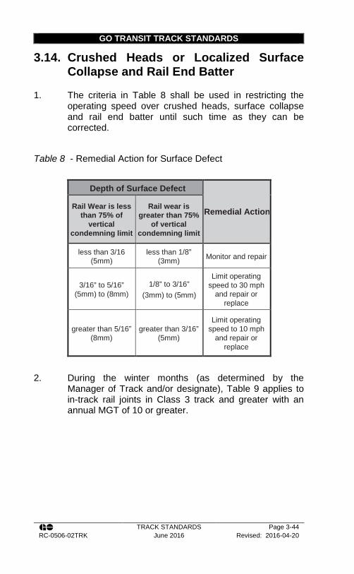
GO TRANSIT TRACK STANDARDS
TRACK STANDARDS Page 3-44 RC-0506-02TRK June 2016 Revised: 2016-04-20
3.14. Crushed Heads or Localized Surface Collapse and Rail End Batter
1. The criteria in Table 8 shall be used in restricting the operating speed over crushed heads, surface collapse and rail end batter until such time as they can be corrected.
Table 8 - Remedial Action for Surface Defect
Depth of Surface Defect
Remedial Action Rail Wear is less than 75% of
vertical condemning limit
Rail wear is greater than 75%
of vertical condemning limit
less than 3/16 (5mm)
less than 1/8” (3mm) Monitor and repair
3/16” to 5/16” (5mm) to (8mm)
1/8” to 3/16” (3mm) to (5mm)
Limit operating speed to 30 mph
and repair or replace
greater than 5/16” (8mm)
greater than 3/16” (5mm)
Limit operating speed to 10 mph
and repair or replace
2. During the winter months (as determined by the
Manager of Track and/or designate), Table 9 applies to in-track rail joints in Class 3 track and greater with an annual MGT of 10 or greater.

GO TRANSIT TRACK STANDARDS
TRACK STANDARDS Page 3-45 RC-0506-02TRK June 2016 Revised: 2016-04-20
Table 9 - Remedial Action for Joint Batter
Joint Batter
>3.5 mm > 4mm >= 5mm • Must be measured twice a week
• must be changed out within 48hours • If rail cannot be changed place a 40mph TSO until it is changed out
• 30mph • Must be changed within 48 hours with no exceptions
3. When rail end joint batter is over 1/8 in (3mm) cross-
level measurements must be taken to ensure a profile or warp situation is not evident. If a profile or warp condition is found to be close to urgent conditions, the condition must be protected as per the track standards.
4. Depth of crushed heads, localized surface collapse and rail end batter shall be determined using a straight edge and a 3/8 in (10 mm) wide taper gauge as per the following diagrams:

GO TRANSIT TRACK STANDARDS
TRACK STANDARDS Page 3-46 RC-0506-02TRK June 2016 Revised: 2016-04-20
3.15. Authorizing Movements Over Rail Breaks
1. This section expands upon practices outlined in Track Standard Section 3.9 through 3.12 and has been developed to provide specific criteria for a qualified employee to authorize a train or engine to proceed safely over rail breaks. a. For the purpose of this section, a rail break shall
be considered a complete break of the rail. b. Thermite weld run-throughs produce conditions
similar to rail breaks. As such, the practice contained herein for movements over rail breaks may be equally applied provided approved weld repair splice bars are applied.
2. A train or engine must not be permitted to operate over a rail break when any of the following conditions exist: a. The rail break is in a tunnel or on an open deck
bridge; b. For supervised moves, the rail break is within
100 feet (30.5 m) of an unanchored open deck bridge;
c. For unsupervised moves, the rail break is within 500 feet (152.4 m) of an unanchored open deck bridge;
d. The ties on either side of the break are defective, crushed, or split in the tie plate area;
e. Cracks are observed radiating from the broken rail ends;
f. The rail break occurs in an area of unstable grade;
g. The offset (overhang) is greater than 2 inches (51 mm);
h. The gap is greater than 3½ inches (89 mm);
GO TRANSIT TRACK STANDARDS
TRACK STANDARDS Page 3-47 RC-0506-02TRK June 2016 Revised: 2016-04-20
i. In the case of a joint area, the break extends beyond the limits of the joint bar; or
j. The break occurs in an area in which the Rail Corridors Senior Manager of Track and Structures has specified that movements over rail breaks are not permitted.
3. Where none of the above conditions exist and joint bars are installed with at least one bolt through the centre of the break trains or engines are allowed to operate over the break at a speed not exceeding 10 miles per hour.
4. When none of the conditions outlined in item 2 exist, the break is not on a ballast deck bridge and the gap size is too small to allow for the installation of joint bars with one bolt through the centre of the break (less 1 1/8” or 29 mm) trains may be permitted to operate over the broken rail at a speed not exceeding 5 mph.
5. If the break is at a weld location and bolt holes exist, splice bars, or temporary weld bars should be installed whenever possible, with at least one bolt in each rail end.
6. The condition of the rail break, splice bars, and supporting ties, must be visually observed as the train or engine operates over the break.
7. The requirement in Item 6 may be waived if the rail break is a significant distance from a location where the employees’ vehicle can be cleared. For example, where there is no other track, grade crossing or road nearby, or where access by foot is impeded by adverse weather conditions provided the following regulatory requirements are met: a. The rail break is:
i. An ordinary break; ii. A complete break in which there is a
sign of a transverse fissure or compound fissure; or
iii. A complete break at a defective weld

GO TRANSIT TRACK STANDARDS
TRACK STANDARDS Page 3-48 RC-0506-02TRK June 2016 Revised: 2016-04-20
b. The condition of the rail break, splice bars and supporting ties must be inspected prior to each movement over the break
c. Not more than 24 hours has elapsed since the initial inspection of the defect, and
d. All unsupervised movements are recorded when reporting the break to the Manager of Track and Track Evaluation Officer.
8. Speed restrictions must be applied in accordance with the applicable operating rules: a. The Rail Traffic Controller, RTC, must be
notified, as to how the restriction is to be applied. One of the following methods must be used: i. Flags placed in accordance with
CROR rule 43; ii. By the use of an approved rail break
sign; or iii. When flags or an approved rail break
sign are not available, restrictions must be applied between two identifiable locations.
9. Temporary bonds may be applied around the rail break where applicable. Upon confirmation that no other rail breaks exist in the block and the application of requisite speed restrictions, trains or engines may be authorized through the block under signal indication. In such cases: a. Temporary bonds should be applied only when
rail repair or replacement is expected to be completed within 72 hours from the time the temporary bonds are installed. Where service application of the bond will extend beyond 72 hours, a permanent bond (exothermic or plug type), approved by the Rail Corridors Signals Manager, will be installed.
b. Track, Welding, S & C and other employees, trained in the application of bonding and rail repair may install temporary rail bonds.
GO TRANSIT TRACK STANDARDS
TRACK STANDARDS Page 3-49 RC-0506-02TRK June 2016 Revised: 2016-04-20
c. The Rail Corridors Signals Manager and the RTC shall be notified whenever temporary rail bond(s) are installed.
d. Temporary rail bonds shall be an approved type and be a maximum of 60 inches (1.5 m) long.
e. The temporary rail bond(s) shall be removed from the track when the final repair or replacement is complete.

GO TRANSIT TRACK STANDARDS
TRACK STANDARDS Page 3-50 RC-0506-02TRK June 2016 Revised: 2016-04-20
If the condition of the rail break, splice bars, and supporting ties, can be visually observed as the train or engine operates over the break, use the following flow chart to determine the appropriate action:
• Is the break in a tunnel or on an open deck bridge?
• Is the break within 100 ft (30.5m) of an unanchored open deck bridge?
• Are the ties on either side of the break defective, crushed, or split in the tie plate area?
• Are visible cracks radiating from the rail ends?• Is the break in an area of unstable grade?• Is the offset (overhang) greater than 2" (51
mm)?• Is the gap greater than 3½” (89 mm)?• Does the break extend beyond the joint bars
(break at joint bar area)?• Is the break in an area in which the Rail Corridors
Chief of Track and Structures has specified that movements over rail breaks are not permitted?
Stop all movements until the rail break has
been repaired
Is the gap smaller than 1-1/8 in. (29 mm)?
Is the break on a ballast deck bridge?
Can joint bars be installed with at least one bolt through the center of the
break?
Speed = 5mphVisually observe each
movement
Stop all movements until the rail break has been
repairedSpeed = 10mph
Visually observe each movement
YES TO ANY
NOTO ALL
YES NO
YES NO
NOYES
Figure 1. – Supervised Movements Over Rail Breaks

GO TRANSIT TRACK STANDARDS
TRACK STANDARDS Page 3-51 RC-0506-02TRK June 2016 Revised: 2016-04-20
• Is the break in a tunnel or on an open deck bridge?
• Is the break within 500 ft (152.4m) of an unanchored open deck bridge?
• Are the ties on either side of the break defective, crushed, or split in the tie plate area?
• Are visible cracks radiating from the rail ends?• Is the break in an area of unstable grade?• Is the offset (overhang) greater than 2" (51
mm)?• Is the gap greater than 3½” (89 mm)?• Does the break extend beyond the joint bars
(break at joint bar area)?• Is the break in an area in which the Rail Corridors
Chief of Track and Structures has specified that movements over rail breaks are not permitted?
Can a movement over the rail break be visually inspected?
See Table 1: Supervised Movements
Is the rail break a significant distance from a location where the employee’s vehicle can be cleared or where
access by foot is impeded by adverse weather conditions?
Stop all movements until the rail break has
been repaired
Has it been more than 24 hours since the initial defect inspection?
Stop all movements until the rail break has
been repaired
Is the gap smaller than 1-1/8 in. (29 mm)?
Is the break on a ballast deck bridge?
Can joint bars be installed with at least one bolt through the center of the
break?
Speed = 5mphVisually observe each
movement
Stop all movements until the rail break has been
repairedSpeed = 10mph
Visually observe each movement
YES NO
YES NO
NOYES
YES TO ANY
NOTO ALL
NO
NO
NO
NO
YES
YES
YES
YES
The rail break is either:• An ordinary break;• A complete break in which there is a
sign of a transverse fissure or compound fissure; or
• A complete break at a defective weld?
YES
Figure 2. – Unsupervised Movements Over Rail Breaks

GO TRANSIT RECOMMENDED METHOD
TRACK STANDARDS Page 3-52 RC-0506-02TRK June 2016 Revised: 2016-04-20
Recommended Method 1303-0 – Classification of Rail
1. When producing and using used rail drilled at one end only, i.e. drilled at the left end, for butt welding, determination of the left end or right end will be made while facing the gauge side of the rail
2. All used rail received at a designated rail storage yard must be classified by a qualified rail inspector.
3. Rail may be classified either on line or at designated rail storage yards. Rail classified at rail storage yards must be ultrasonically tested. All other used rail must be ultrasonically tested as per the GO Transit Ultrasonic Inspection Policy contained in Track Standard Section 18.4
4. The Track Supervisor or equivalent as designated by the Rail Corridors Senior Manager of Track and Structures will be responsible for field classification of rail.
5. When rail is classified, it must be marked with white paint on the web of the rail not more than 3 ft (914 mm) from the end and clear of the splice bars. The marking must be in accordance with the requirements for various classes shown in this Recommended Method and must be placed on the side of the rail that will be the gauge side when rail is laid in track.
6. When rail is reclassified, all previous classification marks must be obliterated.
7. Rails, which when placed on a flat surface having their ends higher than the centre (vertical bend), are acceptable provided they contain a uniform sweep, the middle ordinate of which does not exceed the following:
5” (127 mm) for 78’ (23774 mm) rail
4-1/4” (108 mm) for 72’ (21946 mm) rail
3 1/2” (89 mm) for 66’ (20117 mm) rail
3” (76 mm) for 60’ (18289 mm) rail
1-1/4” (33 mm) for 39’ (11887 mm) rail
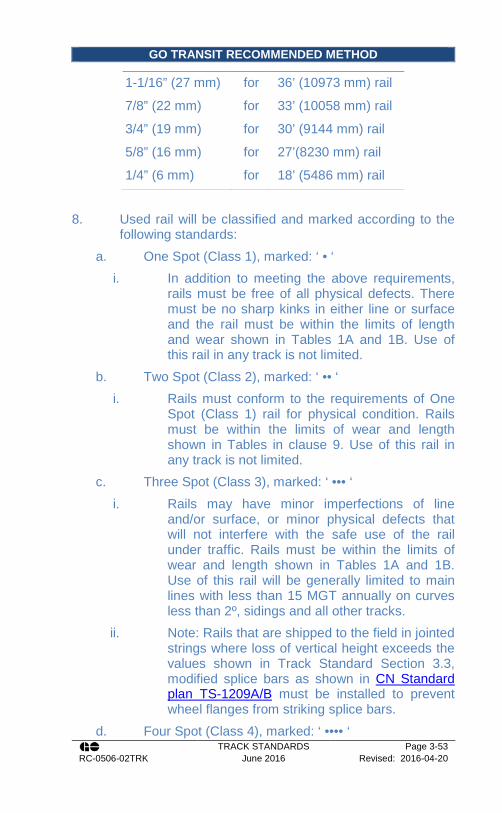
GO TRANSIT RECOMMENDED METHOD
TRACK STANDARDS Page 3-53 RC-0506-02TRK June 2016 Revised: 2016-04-20
1-1/16” (27 mm) for 36’ (10973 mm) rail
7/8” (22 mm) for 33’ (10058 mm) rail
3/4” (19 mm) for 30’ (9144 mm) rail
5/8” (16 mm) for 27’(8230 mm) rail
1/4” (6 mm) for 18’ (5486 mm) rail
8. Used rail will be classified and marked according to the following standards:
a. One Spot (Class 1), marked: ‘ • ‘ i. In addition to meeting the above requirements,
rails must be free of all physical defects. There must be no sharp kinks in either line or surface and the rail must be within the limits of length and wear shown in Tables 1A and 1B. Use of this rail in any track is not limited.
b. Two Spot (Class 2), marked: ‘ •• ‘ i. Rails must conform to the requirements of One
Spot (Class 1) rail for physical condition. Rails must be within the limits of wear and length shown in Tables in clause 9. Use of this rail in any track is not limited.
c. Three Spot (Class 3), marked: ‘ ••• ‘ i. Rails may have minor imperfections of line
and/or surface, or minor physical defects that will not interfere with the safe use of the rail under traffic. Rails must be within the limits of wear and length shown in Tables 1A and 1B. Use of this rail will be generally limited to main lines with less than 15 MGT annually on curves less than 2º, sidings and all other tracks.
ii. Note: Rails that are shipped to the field in jointed strings where loss of vertical height exceeds the values shown in Track Standard Section 3.3, modified splice bars as shown in CN Standard plan TS-1209A/B must be installed to prevent wheel flanges from striking splice bars.
d. Four Spot (Class 4), marked: ‘ •••• ‘

GO TRANSIT RECOMMENDED METHOD
TRACK STANDARDS Page 3-54 RC-0506-02TRK June 2016 Revised: 2016-04-20
i. Rails may have minor imperfections in line and/or surface, or minor physical defects that will not interfere with the safe use of the rail in yard tracks, industrial tracks and light density spurs. Rails must be within the limits of wear and length shown in Tables 1A and 1B.
ii. Note: Rails that are shipped to the field in jointed strings where loss of vertical height exceeds the values shown in Track Standard Section 3.3, modified splice bars as shown in CN Standard Plan TS-1209A/B must be installed to prevent wheel flanges from striking splice bars.
e. Scrap, marked: ‘ X ‘ i. Rails that do not satisfy the above requirements
of the classifications must be scrapped. ii. All rails having horizontal split heads, vertical
split heads, pipes, cracked webs or broken bases due to longitudinal seams or splits, or surface defects that might cause damage to wheels or rolling stock must be scrapped.
iii. Rail arriving at the rail storage yard painted red or marked as scrap shall be immediately scrapped.
f. Rails to be sawn, marked: ‘ S ‘ i. Rails must conform to the requirement of either
One, Two, Three or Four Spot in that portion of the rail that would remain after sawing.
ii. When rail is sawn in the rail yard for classification purposes, the cut must be made a minimum of 4” (100 mm) from any torch cut and a minimum of 6 inches either side of a thermite weld. If bolt holes, batter, or other defects exist, sufficient rail must be cut off to remove the defect.
iii. End cuts must be true and square, a variation of not more than 1/32” being allowed.

GO TRANSIT RECOMMENDED METHOD
TRACK STANDARDS Page 3-55 RC-0506-02TRK June 2016 Revised: 2016-04-20
9. For methods of identifying various types of rail see Clause 11 of this Recommended Method. In case of doubt as to which types of material are most appropriate for various orders, assistance should be requested from Rail Corridors Senior Manager of Track and Structures.
En
d B
atte
r (in
)
1/16
1/16
1/16
1/16
1/16
1/16
Tota
l Wea
r (S
um o
f bot
h si
des
plus
ve
rtic
al w
ear)
(in
)
3/8
3/8
3/8
¼
1/8
1/16
Flan
ge W
ear
(in) Oth
er s
ide
0 0 0 0 0 0
One
sid
e
¼
¼
¼
3/16
1/8
1/16
Loss
of
Vert
ical
Hei
ght
(in)
¼
3/16
3/16
1/8
1/16
1/16
Min
leng
th
(ft)
27
27
27
27
27
27
Cla
ss
• • • • • •
Rai
l Sec
tion
141R
E
136R
E
132R
E
115R
E
100R
A
85
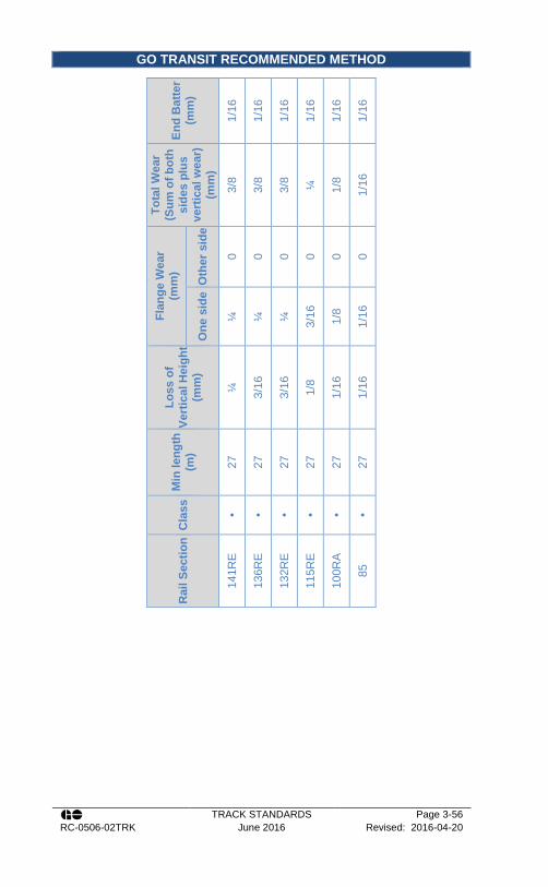
GO TRANSIT RECOMMENDED METHOD
TRACK STANDARDS Page 3-56 RC-0506-02TRK June 2016 Revised: 2016-04-20
End
Bat
ter
(mm
)
1/16
1/16
1/16
1/16
1/16
1/16
Tota
l Wea
r (S
um o
f bot
h si
des
plus
ve
rtic
al w
ear)
(m
m)
3/8
3/8
3/8
¼
1/8
1/16
Flan
ge W
ear
(mm
)
Oth
er s
ide
0 0 0 0 0 0
One
sid
e
¼
¼
¼
3/16
1/8
1/16
Loss
of
Vert
ical
Hei
ght
(mm
)
¼
3/16
3/16
1/8
1/16
1/16
Min
leng
th
(m)
27
27
27
27
27
27
Cla
ss
• • • • • •
Rai
l Sec
tion
141R
E
136R
E
132R
E
115R
E
100R
A
85

GO TRANSIT RECOMMENDED METHOD
TRACK STANDARDS Page 3-57 RC-0506-02TRK June 2016 Revised: 2016-04-20
Carbon Steel Rail Identification on Rail
Web Rail Type Identity Tag
No alloy letter designation in stamp. "M", "MRC", "RC", "Mackie", "CC", "BC", or "VT" will appear in the brand or stamp.
All weights >80 lb. Control-Cooled Nil
"OH" found in brand, and/or all rail rolled by Dominion or Algoma before 1933 and by all other mills before 1939.
All weights except - 115, 132, and 136 lb. Non-Control-Cooled
Nil
HS in stamp (prior to 1976)
100/115/132 Sydney High Silicon Nil
CS in stamp (1976 or later)
100/115/132 Sydney High Silicon Nil
Standard Rail (300BHN) Identification on Rail
Web Rail Type Identity Tag
3HB in stamp, "ALGOMA" in brand Nil or 300HB
3HB in stamp, "SYDNEY" in brand
Sydney 300 BHN Minimum Nil or 300HB
3HB in stamp, "WORKINGTON", "BSC" or "BRITISH STEEL" in brand
British Steel Corp. 300 BHN Minimum Nil or 300HB
3HB in stamp, and "HAYANGE", or "HY" in brand
Sacilor 300 BHN Minimum Nil or 300HB
3HB in stamp and “NKK” in brand
NKK 136 RE 300 BHN Minimum Nil or 300HB
3HB in stamp, "BETH STEELTON" in brand
Pennsylvania Steel Technologies 300 BHN Minimum
Nil or 300HB
3HB in stamp, "TZ" in brand
Moravia Steel 300 BHN Minimum Nil or 300HB
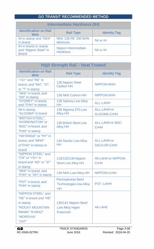
GO TRANSIT RECOMMENDED METHOD
TRACK STANDARDS Page 3-58 RC-0506-02TRK June 2016 Revised: 2016-04-20
Intermediate Hardness (IH) Identification on Rail
Web Rail Type Identity Tag
IH in stamp and “NKK” in brand
NKK 136 RE 330 BHN Minimum Nil or IH
IH in brand or stamp and “Nippon Steel” in Brand
Nippon Intermediate Hardness Nil or IH
High Strength Rail – Heat Treated Identification on Rail
Web Rail Type Identity Tag
"<S>" and "RE" in brand, and "NH", "37", or "T" in stamp
136 Nippon Steel Carbon HH NIPPON-NHH
"NKK" in brand, and "NH" in stamp 136 NKK Carbon HH NIPPON-NHH
"SYDNEY" in brand, and "FHH" in stamp
136 Sydney Low Alloy HH ALL-LAHH
IM in stamp, "ALGOMA" in brand
136 Algoma 370 Low Alloy HH
ALL-LAHH or ALGOMA-CrHH
"BRITISH STEEL", "WORKINGTON" or "BSC" in brand, and "FHH" in stamp
136 British Steel Low Alloy HH
ALL-LAHH or BSC-CrHH
"HAYANGE" or "HY" in brand, and "MHH" or"FHH" in stamp or brand
136 Sacilor Low Alloy HH
ALL-LAHH or SACILOR-CrHH
“NIPPON STEEL” and “CN” or “<S>“ in brand and “AD” or “37” in stamp
115/132/136 Nippon Steel Low Alloy HH
All-LAHH or NIPPON-CrHH
"NKK" in brand, and “FHH" or "AH" in stamp 136 NKK Low Alloy HH NIPPON-CrHH
"PST" in brand, and “FHH” in stamp
Pennsylvania Steel Technologies low Alloy HH
PST- LAHH
“NIPPON STEEL” and “HE” in brand and “HE” in stamp “ROCKY MOUNTAIN RMSM” “EVRAZ” “MOROVIA” “VAT”
136/141 Nippon Steel Low Alloy Hyper Eutectoid
All-LAHE
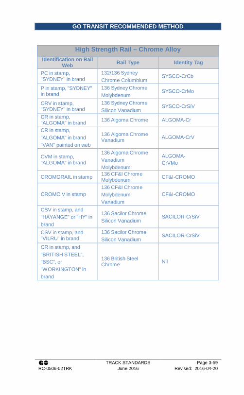
GO TRANSIT RECOMMENDED METHOD
TRACK STANDARDS Page 3-59 RC-0506-02TRK June 2016 Revised: 2016-04-20
High Strength Rail – Chrome Alloy Identification on Rail
Web Rail Type Identity Tag
PC in stamp, "SYDNEY" in brand
132/136 Sydney Chrome Columbium
SYSCO-CrCb
P in stamp, "SYDNEY" in brand
136 Sydney Chrome Molybdenum
SYSCO-CrMo
CRV in stamp, "SYDNEY" in brand
136 Sydney Chrome Silicon Vanadium
SYSCO-CrSiV
CR in stamp, "ALGOMA" in brand 136 Algoma Chrome ALGOMA-Cr
CR in stamp, "ALGOMA" in brand "VAN" painted on web
136 Algoma Chrome Vanadium ALGOMA-CrV
CVM in stamp, "ALGOMA" in brand
136 Algoma Chrome Vanadium Molybdenum
ALGOMA- CrVMo
CROMORAIL in stamp 136 CF&I Chrome Molybdenum CF&I-CROMO
CROMO V in stamp 136 CF&I Chrome Molybdenum Vanadium
CF&I-CROMO
CSV in stamp, and "HAYANGE" or "HY" in brand
136 Sacilor Chrome Silicon Vanadium
SACILOR-CrSiV
CSV in stamp, and "VILRU" in brand
136 Sacilor Chrome Silicon Vanadium
SACILOR-CrSiV
CR in stamp, and "BRITISH STEEL", "BSC", or "WORKINGTON" in brand
136 British Steel Chrome Nil

GO TRANSIT RECOMMENDED METHOD
TRACK STANDARDS Page 3-60 RC-0506-02TRK June 2016 Revised: 2016-04-20
Recommended Method 3700-3 - Unloading Rail
CWR is transported and unloaded by specially designed rail trains. Preparation is critical in unloading rail efficiently. Unloading strings as close as possible to their final position in the track reduces the amount of rail handling necessary. The procedures described in this Recommended Method outline the rail renewal process and the actions that must be undertaken with the utmost regard for safety. There are five major steps in the CWR delivery and unloading process 1. Planning for Rail Renewal
a. Pre-project planning (conducted months prior to the job) Includes emergencies, work environment, materials required, project impediments, work site access, etc.
b. Pre-project planning (conducted weeks before the job) Includes track protection requirements and work blocks
c. Pre-block planning (conducted prior to the work) Includes material and equipment readiness, job briefing, field level risk assessment.
2. Preparation a. Preparation is key to safely and efficiently unloading
rail. In addition, to all the planning and recognized “Best Practices” involved, the following essential preparation will help maintain a safe and productive work environment. Unloading CWR has many inherent risks associated with it. It is therefore essential that a proper and thorough job briefing be performed. The job briefing(s) and Field Level Risk Assessment will include the entire unloading gang, AND the work train crew. It is of utmost importance that all employees engaged in the unloading of CWR have a clear understanding of:
i. The type of track protection and work limits provided
ii. The work to be performed

GO TRANSIT RECOMMENDED METHOD
TRACK STANDARDS Page 3-61 RC-0506-02TRK June 2016 Revised: 2016-04-20
iii. The roles and responsibilities of all employees involved
iv. The identification of all immediate or potential hazards and identifies controls to minimize the risk associated with the identified hazards.
v. The ever changing surroundings, work situation and risk levels and the need for the FREQUENT use of the 4 second focus. A communication plan must be established for all personnel involved in the unloading process. An understanding of this plan must be confirmed with all employees
vi. Utilization of the proper tools for the job vii. The proper procedures for unloading CWR as
outlined in this recommended method. b. Ensure all hardware is present and inspected prior
to use c. Ensure unloading area has been visited prior to
arrival of the rail train to evaluate any safety of other site limitations
d. Rail Unloading Hardware
Figure 3. Rail shoe used to pull rail trough the threader box

GO TRANSIT RECOMMENDED METHOD
TRACK STANDARDS Page 3-62 RC-0506-02TRK June 2016 Revised: 2016-04-20
Figure 4. Rail grip used to anchor rail to track structure
Figure 5. End of one rail connected to the beginning of another being unloaded

GO TRANSIT RECOMMENDED METHOD
TRACK STANDARDS Page 3-63 RC-0506-02TRK June 2016 Revised: 2016-04-20
Figure 6. DO NOT USE CHAINS OR PIGTAILS for rail unloading; use nylon slings or steel cables.
e. The equipment owner and operator is responsible for ensuring that all rail unloading equipment and hardware is in good working condition
f. Winch cables, clevises, turnbuckles, nylon slings, rail grips, head pullers, and steel cables should be present and in good working condition. Verify that the electric impact wrench and generator are operational on the anchor car. Also ensure that the generator has fuel and that there is an extension cord in place.
g. Ensure all location details are known, including: i. List of unloading locations (should be previously
marked in field). ii. Obstructions at unloading area (crossings,
bridges, turnouts, steep embankments, high-

GO TRANSIT RECOMMENDED METHOD
TRACK STANDARDS Page 3-64 RC-0506-02TRK June 2016 Revised: 2016-04-20
degree curves, etc.). These items are to be noted on the Field Level Risk Assessment
iii. Exact length(s) of rail required at each location and side of track on which it is to be unloaded.
iv. Identify prior to the work block which rails require holes to be cut into the ends to facilitate rail shoes or clevis, this may have to be done at both ends of the rail where multiple strings will be unloaded in succession.
v. Single, double or multi-track territory h. Welding Certification Requirements for
Manufacturing of Rail Unloading Hardware shall be from the Canadian Welding Board Certification (all positions)
3. Set up ramp and threader cars a. In order to place the CWR beside the track, two
specialized cars are utilized to guide the rail into position.
i. Ramp Car: Contains adjustable height rollers (movable tables) to match the height of the tier from which rail is being unloaded. This allows the proper angle to be maintained for rail fed through the threader car. This prevents the rail from binding or kinking.
ii. Threader Car: Used to guide rail off the rail train to its final position on the shoulder of the track. It does so by threading it through adjustable roller “threader boxes” mounted on the sides of the car.
iii. Anchor Car: The anchor car secures the rail in place during transit. This car is located near the mid-point of the train. The rail is held place on the anchor car by a plate that is secured with bolts. The electric impact wrench supplied in the tool box on the anchor car can be used to remove the bolts.
b. The following procedure is followed to thread rail through the ramp and threader cars, prior to the actual unloading of rail:
GO TRANSIT RECOMMENDED METHOD
TRACK STANDARDS Page 3-65 RC-0506-02TRK June 2016 Revised: 2016-04-20
i. Step 1: Spot end of threader car at beginning of desired rail-unloading location.
ii. Step 2: Attach rail shoe to leading end of the rail to be unloaded.
iii. Step 3: Guide winch cable(s) through threader box, through threader cone, over moveable tables, and connect to rail shoe (which is already attached to rail to be unloaded).
iv. Step 4: Remove bolts and plates (located at anchor car) from leg of rail to be unloaded.
v. Step 5: Winch rail over adjustable tables, and through threader cone.
vi. Step 6: Attach head-puller assembly onto rail and winch through final threader box. Head puller assembly may have to be reset to complete this task.
c. In order to reduce the risk of personal injury, unloading personnel must not be allowed on the unloading cars, or in the vicinity of the winch cables while rail is being threaded. The only exceptions to this are the winch operator, and the employee controlling the height of the adjustable tables.
4. Unloading Rail a. The following procedure is applicable once the rail
has been threaded through the threader boxes (as described in Part 3 above). If rail is being unloaded on both sides, perform the following procedure for each rail and unload rails simultaneously:
i. Step 1: Ensure end of threader car is located at beginning of desired final rail location.
ii. Step 2: Attach rail grip to the head of the “in-track” rail.
iii. Step 3: Attach cable and turnbuckle between rail grip and rail being unloaded. Ensure turnbuckle is adjusted to shortest position so that any tension from the unloading process can be released by lengthening it.

GO TRANSIT RECOMMENDED METHOD
TRACK STANDARDS Page 3-66 RC-0506-02TRK June 2016 Revised: 2016-04-20
iv. Step 4: Once connected, slide rail grip along rail to tighten cable, and tighten rail grip.
v. Step 5: Slowly move train in the direction that will pull the rail off the train. Unload slowly as to not overheat rollers or cause unnecessary wear. DO NOT EXCEED 10 MPH WHILE UNLOADING RAIL. Considerations to height of embankment, track curvature, etc. must be considered when deciding upon an appropriate unloading speed.
vi. Step 6: Stop the train when the end of the threader car reaches the end of the desired unloading location.
Table 10 - Rail Unloading Scenarios
If... Then... The end of the leg being unloaded is near (i.e. only a short piece is left on the train)
Unload the entire leg, OTHERWISE cut the rail with an oxy-acetylene torch to the required length.
Next unloading area is close (No greater than 1 mile away)
Travel at slow speed with rail in threader box, to next location. Threader box must be tight against the threader car, and rail secured if possible.
Next unloading area is not close
Cut hole in rail, install clevis to secure rail to side of threader car before moving to next unloading area or if possible re- install the anchors in the centre of the train.
vii. Step 7: When rail unloading is finished at a
particular location, the rail grip will be retrieved by the employees who installed it. This is accomplished by lengthening the turnbuckle to remove any tension, then removing the rail grip from the in-track rail.
b. If unloading more than one string of rail at a particular location, insert this step between steps 5 & 6 of the instructions for unloading a single string of rail (listed above).

GO TRANSIT RECOMMENDED METHOD
TRACK STANDARDS Page 3-67 RC-0506-02TRK June 2016 Revised: 2016-04-20
i. Stop the train; do not try to connect the second string until the movement has come to a complete stop. An additional string can be connected to the trailing end of a string being unloaded. This connection is depicted in Figure 5 of this document.
ii. The speed of the movement while threading the second or trailing rail must be slow and controlled (not to exceed 5 mph).
iii. The rail shoe must fit entirely over the face of the trailing rail. The length of cable or nylon sling between two rails connected to be unloaded must not exceed three feet. The operator of the ramp car must ensure that the rail being pulled from the rail train is properly supported as it approached the threader car.
c. In some cases a complete string of rail is not required at the location. This will require that the rail will need to be cut in place utilizing an oxy-acetylene torch. Should this be required follow these recommendations:
i. Only qualified employees are to utilize oxy-acetylene torches
ii. Perform supplemental Job Briefing and FLRA (conditions changed)
iii. Identify personnel required to be in the vicinity and ensure all other employees are clear of the area.
iv. Identify the “line of fire” of the suspended rail, looking ahead to the point at which the cut is complete, where will the rail fall, where will the rail swing.
v. Designate and equip employees to watch for sparks and extinguish embers, hot slag or fires that may ignite.
5. Moving to the Next Unloading Location a. The initial process of threading rail through the ramp
and threader cars is time consuming in comparison to the time it takes to unload one string (generally in

GO TRANSIT RECOMMENDED METHOD
TRACK STANDARDS Page 3-68 RC-0506-02TRK June 2016 Revised: 2016-04-20
the vicinity of 40 minutes to thread and 20 minutes to unload per string). Therefore, it is advantageous to keep rail threaded through the unloading cars as often as possible. In some cases this may be done while in a siding, waiting for track time. Proper track protection must be in place.
b. Limiting the amount of travel between unloading points, i.e. unloading rail at locations that are in close proximity to one another, can greatly reduce the amount of set up time required. However, DO NOT leave rail in the threader boxes unless moves are short. When traveling with rail in the threader boxes, restrict speeds to a maximum of 15 mph if train is making a reverse movement and 25 mph if train is making a forward movement. Please ensure that the locomotive engineer is aware that no sudden stops are to be made at any time. All movements must come to a controlled stop. If rail is fully on the racks and anchors applied, train may travel at track speed.

GO TRANSIT TRACK STANDARDS
TRACK STANDARDS Page 4-1 RC-0506-02TRK June 2016 Revised: 2016-04-20
Section 4 - Joints
4.1. General Information
1. In conventional jointed track, each rail shall be bolted with at least two bolts at each joint in Classes 2 through 5 tracks and with at least one bolt in Class 1 track.
2. In the case of Continuous Welded Rail (CWR) track, each rail shall be bolted with at least two bolts at each joint.
4.2. Conventional Joints
1. Proper drilling techniques must be exercised to protect against the harmful effects created by unsuitable drilling practices. Proper drilling techniques will also increase the useful life of drill bits. It is recommended that the edges of all holes be deburred or chamfered to eliminate notches associated with stress concentrations at the holes. Refer to Recommended Method 3700-0 – Drilling Holes in Rail for details.
2. Rail bolt holes will be located using the correct indexing bar. The indexing bar will be placed so that the edge of the indexing bar matches the end of the rail
3. Only joint bars of the correct design for the rail section, drilling pattern, and bolt type will be used.
4. All joints in CWR territory must be inspected at a minimum frequency of that shown in Appendix A – Track inspection frequencies on Table 36.
5. In Class 3 track and above, joint bars that are broken, cracked or allow vertical movement of either rail when all bolts are tight should be replaced immediately.
6. Joint bars that are cracked or broken between the middle two bolt holes regardless of the class of track must be replaced immediately.
7. Rail joints should be slotted to prevent flowed rail and chipped joints.
GO TRANSIT TRACK STANDARDS
TRACK STANDARDS Page 4-2 RC-0506-02TRK June 2016 Revised: 2016-04-20
8. Where 33 ft. (10 m) to 39 ft. (11.9 m) panels are installed and three or more consecutive square joints exist, speed will be limited to that of class 3 track.
4.3. Insulated Joints
1. Defective insulated joints must be repaired or replaced immediately.
2. Signal forces must report defective insulated joints to track forces promptly.
3. Signal forces must advise the track forces of the location of insulated joints for proper signal operation. The location must not be changed without the approval of the Rail Corridors Manager of Signals.
4. Bonded insulated joints are to be used in CWR. 5. Encapsulated (coated) insulated joints are to be used in
jointed rail sections. 6. Fibre bars may be used in light rail sections. 7. Plates must be used with all insulated joints on wood
track ties. As shown on CN Standard Plan TS-1206, insulated tie plates will be used on ties within 2” of the end post of an insulated joint.
8. Proper insulated joint clip fully driven in place must be used when Pandrol tie plates or concrete ties are used.
9. Insulated joints should be suspended (the end post should not be over a tie).
10. Rail ends where insulated joints are to be installed must conform to the following: a. The end face shall be saw cut and bolt holes
drilled to the proper size and location for the rail section.
b. All rough edges and burrs shall be removed from the end face and the bolt holes.
c. Batter shall not exceed 1/32 inch (0.75 mm). d. The heights of the adjacent rails shall not differ
by more than 1/16 inch (1.6 mm).

GO TRANSIT TRACK STANDARDS
TRACK STANDARDS Page 4-3 RC-0506-02TRK June 2016 Revised: 2016-04-20
11. All rust, scale, dirt or other foreign matter must be removed from the rail joint area and from the joint bars before the joint is installed.
12. If the end post projects above the top of rail, it must be trimmed so that the top is below the top of rail, but not exceeding 1/8 inch (3.2 mm) below.
13. Track near insulated joints shall be adequately anchored. Non-glued insulated joints will be considered as joints and will be anchored to the correct standard.
14. Rail anchors must not be applied on the sides of ties adjacent to bootlegs.
15. Rail end overflow must be removed at insulated joints by slotting in accordance with CN Standard Plan TS-1113. The gap should be filled with silicone sealer to prevent the influx of dirt and grinding material.
16. After welding, insulation must not be replaced until the rails have cooled.
17. Insulated joints that are no longer required, must be removed from track within 72 hours.
18. At insulated joints tie spacing shall be 19½ in. (495 mm) for non-continuous insulated joints, and 18 in. (457 mm) for continuous insulated joints.
19. On heavy traffic lines (30 MGT per year or greater), 9ft ties may be used between each pair of insulated joints. On all other lines 8’-6” ties are acceptable.
20. Insulated joints shall be staggered at a maximum of 4 ft-3 in in (1 m) for non-continuous insulated joints, and a maximum 4 ft-6 in for continuous insulated joints.
4.4. Compromise Rails and Joints
1. To determine the hand of the joint, face the joint from the centre of the track. When the larger rail section is on the left side of the joint, it is a left hand joint. When the rail of larger section is on the right, it is a right hand joint.
2. A compromise joint consists of one gauge side and one field side bar. The rail sections that the compromise bar will fit are indicated at each end of the bar.

GO TRANSIT TRACK STANDARDS
TRACK STANDARDS Page 4-4 RC-0506-02TRK June 2016 Revised: 2016-04-20
3. Compromise joint bars must not be modified from their initial design to fit a different rail section.
4. Compromise joints (except 132/136 RE) must not be installed in turnouts, or within 20 ft. (6.1 m) of an open deck bridge, turnout, highway crossing or railroad crossing.
5. Compromise joint should be painted a colour designated by the Senior Manager of Track and Structures.
6. Compromise rails consist of a single piece of rail, with a forged transition from one rail section to another. Compromise rails may be universal or “handed”, depending on the rail sections, and are identified just as a joint would be.
7. Compromise rails will be fully supported and tamped with the correct size tie plates under the corresponding rail section.
8. Compromise bars are ONLY permitted in non-main tracks, main tracks in Class 1 and 2, and main tracks having less than or equal to 10 MGT annually.
GO TRANSIT RECOMMENDED METHODS
TRACK STANDARDS Page 4-5 RC-0506-02TRK June 2016 Revised: 2016-04-20
Recommended Method 3700-0 – Drilling Holes in Rail Rail Drills: The various models of rail drills or approved equivalent are recommended to be used on GO Transit territory may be classified into two categories, as outlined below; 1. Gas Powered Drills (Supplied by Modern Track
Machinery) a. Model PR8 c/w speed bit advance
i. engine speed – 3600 rpm ii. spindle feed rate – 130 rpm iii. feed rate:
• low: 0.002” (0.04mm)/rev
• medium: 0.0049” (0.125mm) /rev
• high: 0.0098” (0.25mm) / rev b. Model PR3AA-2S High precision automatic
advance/stop i. engine speed – 3600 rpm ii. spindle feed rate – 130 rpm for standard rail and
80 rpm for hardened rail iii. feed rate: 0.0051” (0.130mm) / rev iv. drilling time will vary:
• Standard Carbon Rail (275-320 BHN) 60-90 seconds
• Premium rail (321-360 BHN) 90-120 seconds
v. Note: this model is equipped with a manual “over-ride” which, when activated allows the operator to manually feed the drill bit to the rail. Manual operation is not recommended except in the case of a mechanical problem.
2. Hydraulic Drills (Supplied by Stanley Tool Company) a. Model RD11 Stanley Rail Drill – used with flat drill bit
GO TRANSIT RECOMMENDED METHODS
TRACK STANDARDS Page 4-6 RC-0506-02TRK June 2016 Revised: 2016-04-20
i. set relief valve at power source to 2350 psi ii. hydraulic working full load pressure: 2000 psi iii. max. back pressure: 250 psi iv. oil flow: 5gpm or 10gpm (both acceptable) v. spindle feed rate: 90 - 180 rpm vi. drill time: 90 - 120 seconds
b. Model RD12 Stanley Rail Drill – used with carbide tipped bits attached to a bit holder
i. set relief valve at power source to 2350 psi ii. hydraulic working full load pressure: 2000 psi iii. maximum back pressure: 250 psi iv. oil flow: 10 gpm (critical) v. spindle feed rate: 900 RPM vi. drill time: 40 sec. (approx.)
Drill Bits: GO Transit uses two types of drill bits: 1. Flat drills bits 2. Carbide tipped coring drill bit At present, all rail drills except the model RD 12 hydraulic drill use flat drill bits. The RD 12 uses the carbide tipped coring bits as in Figure 7 Note: There are two carbide-titanium coated tipped bits on each bit “holder”. Each carbide tip is designed with four cutting faces. When a cutting edge is dull, (approximately 35 holes), the cutting tip can be rotated 90 degrees to the next face, etc. Both cutting tips should be rotated at the same time. The total number of holes per set of cutting tips should be 140-200 holes. The tool bit holder is estimated to last upwards of 2000 hole-drillings with proper drilling techniques.

GO TRANSIT RECOMMENDED METHODS
TRACK STANDARDS Page 4-7 RC-0506-02TRK June 2016 Revised: 2016-04-20
Figure 7. – Carbide Tipped Coring Bit Lubrication: When all other requirements for speed, feed and drilling times are met, the expected life of a drill bit could be reduced by one half, if proper lubrication is not provided. Lubrication must be applied to the tip of the bit while drilling. The following practices apply to lubrication while drilling: 1. A continuous flow of lubricant must be directed at the
drilling bit tip to be effective. Approved oil such as “Castrol” or cutting machine oil should be used. Water soluble coolant (can be diluted with water) is the next preferred lubricant. Approved oil will outperform water, and water will outperform dry drilling. Antifreeze works well in cold weather.
2. When using an antifreeze mixture, remember to be environmentally friendly and use a biodegradable brand wherever possible.
3. Carbide tipped coring bits (RD12 drills) require lubrication at all times and must not be permitted to drill dry. In order to ensure a continuous flow of lubricant to
Cutting Tips
Bit Holder

GO TRANSIT RECOMMENDED METHODS
TRACK STANDARDS Page 4-8 RC-0506-02TRK June 2016 Revised: 2016-04-20
the drill bit, use of a garden weed sprayer (Figure 8) filled with the appropriate lubricant is recommended.
4. Dry drilling with flat bits is not a recommended practice. It is however, a safeguard against intermittent lubrication practices (described in the next statement) when continuous lubrication cannot be provided on flat bits.
5. Intermittent cooling/lubrication using snow or water is not permitted as it can be more damaging than dry drilling. The hole area may become superheated and quenched, increasing the hardness of the hole so much that the drill bit will no longer cut properly.
6. Never throw snow or water onto drill bits. This will introduce further problems associated with production of brittle untempered martensite in the rail and drill bit.
Figure 8. – Typical Garden Weed Sprayer Drilling with Flat Bits:

GO TRANSIT RECOMMENDED METHODS
TRACK STANDARDS Page 4-9 RC-0506-02TRK June 2016 Revised: 2016-04-20
Flat bits are used in the following rail drills:
• PR8 -Gas powered Drill (Modern Track)
• PR3AA-2S -Gas powered Drill (Modern Track)
• RD 11 -Hydraulic Drill (Stanley) When drilling with flat bits the following actions shall be followed: 1. Drilling speed shall be set at the requirements set out by
the drill bit manufacturer. In the case of flat bits used with gas powered drills, the recommended speed is between 110-130 rpm.
2. Ensure drills are checked regularly for recommended rpm’s. Drilling speed and feed rates are very important. Drilling speeds out of adjustment will affect the feed rate and decrease the life of the drill bit, increasing drilling problems.
3. Feed rates are preset by the drilling speed. If drilling speed is correct the feed rate will be correct as well.
4. Drilling must be closely timed using a stop watch or other reliable method.
5. Watch the feed screw while the machine is drilling. If it stops turning that means the drill bit is not cutting and the machine should be stopped.
6. Drilling a hole should take about 90 seconds to a maximum of two minutes and 30 seconds depending on drill and type of bit being used. Drilling times longer than 2 min. 30 sec are generally a result of a dull or dulling drill bit. At that point the flat drill bits should be discarded or re- sharpened where applicable.
7. The drill bit must be properly seated and secured into the deepest position of the chuck. Never hammer the bit into the rail.
8. The drilling machine must be properly aligned with the proper rail guide.
9. Ensure drill is properly supported to avoid any excess movement during the drilling operation. Excessive movement can result in imperfect holes and premature wear or breakage of drill bits.
GO TRANSIT RECOMMENDED METHODS
TRACK STANDARDS Page 4-10 RC-0506-02TRK June 2016 Revised: 2016-04-20
10. Never change the speed of the drilling machine to complete a hole. If machine starts to labour, never force the bit through the hole. The bit is probably dull and should be changed. Again pay close attention to the drilling time.
11. Never force the drill to complete a hole by manual operation of the feed.
12. Damaged or dull bits must not be used. 13. A qualified mechanic must check the condition of your
drilling machine at least once per year. Where a large number of drills are in use, a routine maintenance program should be set up to allow for cycled maintenance of the drills, and to ensure that all drills are checked yearly.
14. Whenever cycled maintenance has been performed, drill should be tagged with last maintenance date and next due date.
15. Hydraulic drills can have their drilling time altered to a much greater degree than gas powered drills. The best recommendation is to pay close attention to the drilling times previously mentioned. The extra friction and heat produced by exceeding the recommended drilling times can destroy the cutting edge of the bit and result in poor surface finishes and poor durability of the hole.
Changing a Flat Drill Bit part way Through a Hole: 1. To change a bit part way through a hole, keep spindle
properly aligned with the hole and do not unclamp the drilling machine from the rail.
2. Back the bit out of the hole and strike the ejector with a hammer to release the chuck. To ensure the hole remains lined up, never remove the drill when changing bits.
Drilling with Carbide Tipped Coring Bits:
GO TRANSIT RECOMMENDED METHODS
TRACK STANDARDS Page 4-11 RC-0506-02TRK June 2016 Revised: 2016-04-20
The model RD 12 hydraulic rail drill (see Figure 9) is used with carbide tipped coring bits. The following practices shall be observed: 3. Wipe all hose connections with a clean lint-free cloth
before making connections. 4. Connect the hoses from the hydraulic power source to
the hose couplers at the tool. It is a good practice to connect the return hose first and disconnect it last to minimize or avoid tapped pressure within the drill.
5. Observe flow indicators stamped on hose couplers to be sure that oil flow is in the proper direction. The female coupler is the inlet coupler.
6. The RD12 rail drill is equipped with a separate coolant assembly that is used to deliver coolant to the drill bit. Ensure this is operating properly before drilling.
7. Connect the coolant assembly to the rail drill using the supplied quick- disconnect coupler.
8. Make sure the carbide inserts on the drill bit have good cutting edges. If the surfaces are worn or chipped, unscrew the retaining screw and rotate the insert to a good cutting surface.
9. Install the drill bit into the piston assembly then turn clockwise.
10. RD12 Drills must be used with rail templates and hole guides.
11. The drilling machine must be properly aligned with the proper rail guide. Never use joint bars as a guide.
12. Ensure drill is level and very tight 13. When clamping the drill to the rail, double check to
ensure clamping pressure. If loose, the drill will skid down the rail and bits will be destroyed.
14. Drilling speed shall be set at the requirements set out by the supplier. The spindle feed rate for the RD12 is 900 rpm @ 10 gpm.
15. Drilling speed and feed rates are very important. Drilling speeds out of adjustment will affect the feed rate and decrease the life of the carbide bit, increasing drilling
GO TRANSIT RECOMMENDED METHODS
TRACK STANDARDS Page 4-12 RC-0506-02TRK June 2016 Revised: 2016-04-20
problems. Ensure drills are checked regularly for recommended rpm’s, oil flow and pressures.
16. Feed rates are preset by the drilling speed. If drilling speed is correct the feed rate will be correct as well.
17. Drilling must be closely timed using a stop watch or other reliable method.
18. Watch the feed screw while the machine is drilling. If it stops turning that means the drill bit is not cutting and the machine should be stopped.
19. Drilling a hole with the RD 12 drills with carbide tipped coring bits should take 40-60 seconds. Drilling times longer than 60 seconds are generally a result of a dull or chipped carbide bits and the bits should then be rotated.
20. Pay close attention to the drilling times previously mentioned. The extra friction and heat produced by exceeding the recommended drilling times can destroy the cutting edge of the bit and result in poor surface finishes and poor durability of the hole.
21. The tool bit holder must be inserted into the deepest position of the chuck, properly seated and secured.
22. Do not run out of coolant. If this happens the drill bits will only last approximately 10 seconds, the cutters will break and the tool bit holder will be ruined and difficult to remove.
23. Check cutters every 3 or 4 holes for condition. Cutters should get approximately 30 holes before requiring rotation.
24. Remove drill bit while in transit to avoid damage to the cutters.
25. Remove tool holder out of spindle and place a rag in the spindle for transit.
26. Use the correct template for the size of rail you are drilling.
27. A qualified mechanic must check the condition of your drilling machine at least once per year. Where a large number of drills are in use, a routine maintenance program should be set up to allow for cycled

GO TRANSIT RECOMMENDED METHODS
TRACK STANDARDS Page 4-13 RC-0506-02TRK June 2016 Revised: 2016-04-20
maintenance of the drills, and to ensure that all drills are checked yearly.
28. Whenever cycled maintenance has been performed, drill should be tagged with last maintenance date and next due date.
Figure 9. – RD12 Hydraulic Rail Drill Safety Precautions: 1. Operators of drills must be familiar with prohibited work
areas such as excessive slopes and dangerous terrain conditions.
2. Supervisors must ensure that proper training has been received to ensure safe operation of drills by their operators.
3. Always wear safety equipment such as goggles, ear and head protection, safety shoes and reflectorized apparel while operating a drill.
Coolant Can
Knob and threaded Shalft Adjustment Screw for Hole Guide
Handle
Piston Machine Assembly Coolant Connection
GO TRANSIT RECOMMENDED METHODS
TRACK STANDARDS Page 4-14 RC-0506-02TRK June 2016 Revised: 2016-04-20
4. Do not overreach. Maintain proper footing and balance at all times.
5. Do not inspect, replace the drill bit or clean the tool while the power source is connected. Accidental engagement of the tool can cause serious injury.
6. Always connect hoses to the tool hose couplers before energizing the hydraulic power source. Be sure all connections are tight.
7. Never wear loose clothing that can get entangled in the working parts of the drill.
8. To avoid injury or equipment damage, all drill repairs, maintenance and service must be performed by authorized and properly trained personnel.
9. Always check bits for damage and chips out of the chisel edge points and roundness of the cutting edges before each use. Any damage to the bits will affect the ability of the bit to drill a hole. Damaged bits should be removed from further use.
10. Keep hands and fingers away from rotating parts. 11. Handle drill bits with care. They are a precise cutting
tool. Avoid hitting of the drill bits against other surfaces. 12. If drilling time is beyond the 2.5 minute limit (or 1 min. for
the carbide tipped coring bits) STOP the machine and change the drill bit or rotate cutters. Never let a dull bit heat up the rail.
13. Record the number of holes drilled with each bit as well as the drilling time. As time nears the maximum time period it is time to change the drill bit.
14. Discard old flat bits that will not be re-sharpened so they do not get used again. Coring bits can have the carbide tips rotated or replaced. Do not discard these bits
15. Consistent and good lubrication is necessary. Dry drilling is better than inconsistent lubrication in the case of PR8, PR3AA and RD11 drills.
16. RD12 Rail drills and bits must have good lubrication, dry drilling is not permitted.
17. Always ensure manufacturer’s recommendations are followed.

GO TRANSIT RECOMMENDED METHODS
TRACK STANDARDS Page 4-15 RC-0506-02TRK June 2016 Revised: 2016-04-20
18. Ensure any burrs, fins and sharp edges are removed after each drilling operation using a round, rat tail file, with a medium cut.
Quality Assurance: If for any reason it is felt that a quality issue exists with new drill bits ensure the following: 19. Drill (machine) is functioning properly. 20. Proper procedures have been followed. 21. Good lubrication has been provided. 22. Drill bit has not been damaged through rough handling. 23. Ensure hydraulic pump drive belt is properly adjusted. If the above has been followed and problems still exist contact your immediate supervisor. Document all pertinent details and information for warranty or claim.

GO TRANSIT TRACK STANDARDS
TRACK STANDARDS Page 5-1 RC-0506-02TRK June 2016 Revised: 2016-04-20
Section 5 - Rail Grinding
5.1. Rail Grinding with Self Propelled Grinding Machines
1. Where practical, crossing surfaces adjacent to the rails should be removed. This will permit grinding across the entire rail head and applies to both the large out-of-face grinders and the switch and crossing grinders.
2. Rail segments through hot box detectors, wheel impact detectors etc. shall not be ground unless the Signals Department has arranged to protect such installations.
3. Rail Lubricator actuators, ramps, wiping bars and other parts which might be damaged must be lowered or removed prior to rail grinding operations but must be placed back in service immediately following grinding.
4. Rail grinding profiles and frequencies will be as specified by the Rail Corridors Senior Manager of Track and Structures.
5. Rail that is scheduled for removal should be ground prior to removal, to improve its condition for the next position, if it is: a. Destined to a rail yard for classification; b. To be used for maintenance rail; c. To be used for direct field cascading
6. Corrective grinding should be undertaken when: a. Corrugation exists to the extent that the average
slope from peak to trough of the corrugation exceeds 0.002 inches per inch (0.002 mm/mm); or
b. The running band requires correction 7. Before grinding commences, the following preparation
work must be done: a. A complete survey of the rail condition shall be
made;
GO TRANSIT TRACK STANDARDS
TRACK STANDARDS Page 5-2 RC-0506-02TRK June 2016 Revised: 2016-04-20
b. The track must be in good surface, gauge and line;
c. To the extent possible, all replacement rail should be installed and field welds made;
d. Engine burns, rail end batter, stock rail batter or any other discrete defects which would be deeper than 0.010” (0.25 mm) after the planned grinding, should be repaired or removed prior to grinding;
e. Areas that cannot be repaired economically, or that habitually deteriorate at a rate greater than that of the adjacent rail, should be removed and replaced with permanent closures prior to grinding.
8. A Track Supervisor, whose responsibilities include the following, shall accompany the grinding machine: a. Perform pre-inspections of rail condition and
select the appropriate grinding pattern(s) and desired speed;
b. Ensure that there is adequate communication between the control operators and the conductor;
c. Ensure that the machine progress and performance is optimum;
d. Ensure metal removal and levelling tests are performed on a regular basis;
e. Coordinate fire patrols during the periods of the year when such patrols are necessary and communicate regularly with appropriate fire protection agencies;
f. Keep a daily log of machine performance and ensure that the daily reports are correct; and
g. Inspect around insulated joints, turnouts, and other locations where filings could disrupt the signal system.
h. Ensure, when practicable, on-track lubricators are applying grease to the gauge corner of the high rail and to the top of the low rail on newly

GO TRANSIT TRACK STANDARDS
TRACK STANDARDS Page 5-3 RC-0506-02TRK June 2016 Revised: 2016-04-20
ground curves prior to the passage of train traffic.
9. After grinding is complete the rail head should display the following conditions: a. On curves, a 1-1/2” to 1-3/4” (38-44mm) wide
running band on both rails. i. The high rail is to exhibit a slightly
conformal profile to assist natural gauge corner wear (gauge corner grinding marks should be worn off after 7 to 15 MGT); and
ii. The low rail is to exhibit an 8” to 10” (203 - 254 mm) crown radius, with field side relief, in order to minimize false flange damage.
b. On tangent track and in turnouts, a 1-1/2” to 1-3/4” (38-44 mm)running band centred on the rail;
5.2. Frog and Switch Grinding
1. When grinding turnouts with a frog and switch grinder, the following procedures will apply: a. The frog shall not be ground. The grinding
wheels should be raised at the last joint (or weld) before the frog and lowered at the first joint (or weld) after the frog. Pick up and set down points should be consistent within 12” (305 mm);
b. Normally, point rails shall not be ground between the point end and the end of the head side planning (except in the case of c below);
c. When the difference between the vertical dimension of the running surface of the switch point and the stock rail, in the riser area, is reduced by wear to 3/16" (5mm) , the stock rail and/or the switch point may be ground to restore the ¼" - 5/16" (6-8 mm) dimension (See Track Standard 0); and
GO TRANSIT TRACK STANDARDS
TRACK STANDARDS Page 5-4 RC-0506-02TRK June 2016 Revised: 2016-04-20
d. At switches and crossings, grinding shall continue for 80 ft (24.3m) beyond the point of switch and heel of frog. This ensures a smooth transition zone.
2. If necessary, the switch and crossing grinder may be used to grind spots on tangents and curves that would be otherwise uneconomical to grind with a large grinder.
5.3. Rail Grinding Near Bridges and Structures
1. Grinding is NOT to be performed within 50 feet (15.25 m) on either side of any structure that is not scheduled for grinding unless this area, including the first 200 feet (61 m) of the bridge deck, is wetted down with a fire retardant foam/water mixture. In this case, grinding can be performed to within 25 feet (7.6 m) on either side of the structure.
2. Whenever possible, rail grinding on bridges should be scheduled during winter months or under wet weather conditions.
3. During the pre-grinding survey inspections the Grinding Supervisor along with the Track Supervisor will establish and agree on a list of bridges to be ground.
4. The Track Supervisor or Rail Corridors Manager of Track will then contact the Rail Corridors Manager of Bridges and Structures and notify them of the bridge(s) to be ground.
5. The Rail Corridors Manager of Bridges and Structures must then examine the structure(s) for fire hazards and provide an assessment of the risks that are present. This assessment will include: a. A mitigation plan for each structure, which will
outline the precautions to be taken in terms of additional fire protection. This mitigation plan must also include the following: i. Requirements for post grind patrols. ii. List of local fire department contacts
GO TRANSIT TRACK STANDARDS
TRACK STANDARDS Page 5-5 RC-0506-02TRK June 2016 Revised: 2016-04-20
iii. Any specific fire suppression requirements unique to a structure (i.e. Presence of local Fire Department required).
iv. Any special requirements for removal of fire susceptible material near and under the bridge.
6. Prior to grinding, the Grinding Supervisor must ascertain from the Track Supervisor that: a. All bridges on the grinding list have been
inspected for fire hazards and assessed by the Manager of Bridges and Structures; and,
b. All fire precautions and patrols are in place as outlined in the mitigation plan.
c. If all these conditions cannot be ascertained, then NO grinding of the bridge(s) shall be done.
7. The grinding train must not leave the structure until either a patrol or the fire truck is physically in place. A thorough job briefing must be performed and such persons must understand their duties. They must have suitable fire-fighting equipment (at least 3 Wajax cans filled with water or preferably a water/foam retardant mixture) and know how to operate them. The foam mixture is much more effective than water alone.
8. The fire suppression systems on the grinding train must be equipped with a fire retardant foam/water mixture. Any timber structure is to be ground must be wetted down prior to grinding to reduce the risk of fire. Grinding train ditch and tie sprays must be operated continuously during the entire bridge grinding operation.
9. On timber structures, once grinding is complete, run the grinding train with ditch and tie sprays operating over the entire bridge including 200 feet (61 m) on each side at least once to wet down any sparks that may have been left by the grinding operation. This train movement should be done at a constant speed without any sudden stops to avoid dislodging slag and swarf from the grinding train.

GO TRANSIT TRACK STANDARDS
TRACK STANDARDS Page 5-6 RC-0506-02TRK June 2016 Revised: 2016-04-20
10. When grinding in the area of timber bridges and trestles, a fire inspection must be performed after passing over these structures.
GO TRANSIT TRACK STANDARDS
TRACK STANDARDS Page 6-1 RC-0506-02TRK June 2016 Revised: 2016-04-20
Section 6 - Rail Lubrication
6.1. Way-Side Lubricators
1. All new curves of 2º and greater in main line tracks shall be protected by a wayside lubrication system at the discretion of the Rail Corridors Senior Manager of Track and Structures.
2. All new curves over 6º must be protected by a wayside lubrication system and be subjected to the criteria stated herein. All existing curves shall be upgraded to comply with this Standard.
3. Locations for lubricators shall be determined through the following criteria: a. Lubricators should be located away from water-
courses, road crossings, turnouts, open deck bridges, hot box detectors and Signal & Communications installations.
b. Lubricators shall be kept at least 100 ft. (30.5 m) from insulated joints.
c. Lubricators should be located away from stopping points, and normal points of sanding, sink holes, and frost heave areas.
d. Carrying properties of the grease; e. Grade of track; and f. The total central angle of curves
i. Each curve will have a Total Central Angle of Curvature calculated using the formula:
𝑇𝑇𝑇𝑇𝑇𝑇 =𝐷𝐷𝑐𝑐 ∙ �𝐿𝐿𝑐𝑐 ∙ 1
2� ∙ (𝐿𝐿𝑠𝑠1 + 𝐿𝐿𝑠𝑠2)�100
𝐷𝐷𝑐𝑐 = 𝑑𝑑𝑑𝑑𝑑𝑑𝑑𝑑𝑑𝑑𝑑𝑑 𝑜𝑜𝑜𝑜 𝑐𝑐𝑐𝑐𝑑𝑑𝑐𝑐𝑑𝑑
𝐿𝐿𝑐𝑐 = 𝐿𝐿𝑑𝑑𝐿𝐿𝑑𝑑𝐿𝐿ℎ 𝑜𝑜𝑜𝑜 𝑐𝑐𝑐𝑐𝑑𝑑𝑐𝑐𝑑𝑑
𝐿𝐿𝑠𝑠1 = 𝑙𝑙𝑑𝑑𝐿𝐿𝑑𝑑𝐿𝐿ℎ 𝑜𝑜𝑜𝑜 𝑑𝑑𝐿𝐿𝐿𝐿𝑑𝑑𝑒𝑒 𝑠𝑠𝑠𝑠𝑠𝑠𝑑𝑑𝑠𝑠𝑙𝑙

GO TRANSIT TRACK STANDARDS
TRACK STANDARDS Page 6-2 RC-0506-02TRK June 2016 Revised: 2016-04-20
𝐿𝐿𝑠𝑠2 = 𝑙𝑙𝑑𝑑𝐿𝐿𝑑𝑑𝐿𝐿ℎ 𝑜𝑜𝑜𝑜 𝑑𝑑𝑒𝑒𝑠𝑠𝐿𝐿 𝑠𝑠𝑠𝑠𝑠𝑠𝑑𝑑𝑠𝑠𝑙𝑙 The coverage for a single wayside lubricator will be determined when the sum total of TAC values for successive curves reaches 600.
4. Track conditions at the location of the lubricator shall be as follows: a. Rail wear should be such that the wiper blades
are not damaged by passing wheels. b. Gauge at the lubricator must be maintained to
56-1⁄2 in. (1435 mm). c. Lubricators must NOT be installed on concrete
ties with worn insulators. d. On wood ties, ties will be fully spiked for 30ft
(9.2 m) on either side of the lubricator. e. All track ties within the limits of the applicator
bars must be sound and free of plate cutting. f. All other track material, such as tie plates,
spikes, etc., must be in good condition. 5. Lubricators will be installed in accordance with the
manufacturer’s instructions. a. Stopping points, normal points of sanding, sink
holes and frost heave areas should be avoided. 6. Track will be covered with woven geotechnical fabric for
a distance of 50 ft. (15.2 m) either side of a wayside lubricator.
7. The type of lubricators to be installed shall be approved by the Rail Corridors Senior Manager of Track and Structures.
8. Electric lubricators (solar powered or 120 Volt AC) are recommended for all new installations.
9. The location of electric lubricators should be selected in consultation with the S&C department, which will advise on electric power availability.
10. Electrical hook-ups to electric lubricators must be made by qualified personnel. Ground Fault Circuit Interrupters must be used on all 120 Volt installations.
GO TRANSIT TRACK STANDARDS
TRACK STANDARDS Page 6-3 RC-0506-02TRK June 2016 Revised: 2016-04-20
11. Solar panels for electric lubricators must be located and mounted according to manufacturer's instructions, where the maximum amount of sunlight will be obtained. The use of a protective shield is recommended to prevent damage to the solar panels.
12. The batteries of electric lubricators must be protected from freezing in the event of a total discharge.
13. The exact locations of installation shall be determined in the field.
14. Maintenance of the lubricators shall include, but not be limited to: a. Lubricators must be inspected on foot at least
once per month. b. In track circuit territory, including but limited to
CTC territory or in a crossing approach, care must be taken to ensure that no part of the lubrication system grounds or shorts out the rails. This includes checking that metal reinforced hoses do not contact the rails, and ensuring that the lubricator does not interfere with broken rail protection.
c. The lids of lubricators must be kept locked except when maintenance is being performed.
d. Hydraulic fluid levels in hydraulically activated lubricators must be checked and filled according to manufacturer’s instructions.
e. Mechanical pump drive connections must be inspected and lubricated on a regular basis.
f. All hold-down bolts, clamps, etc., kept tight. 15. Lubricator actuators, ramps, wiping bars and other parts
which might be damaged must be lowered or removed prior to rail grinding operations but must be placed back in service immediately following grinding.
16. As grease interferes with proper ultrasonic testing, all lubricators must be shut off sufficiently in advance of any Ultrasonic Rail Testing to ensure no grease is present. Lubricators must be reactivated immediately after testing.

GO TRANSIT TRACK STANDARDS
TRACK STANDARDS Page 6-4 RC-0506-02TRK June 2016 Revised: 2016-04-20
17. The area immediately around lubricators must be kept as clean as possible. Packaging materials and contaminated grease must be disposed of in an approved manner.
18. GO Transit does NOT permit any top of rail lubrication.
6.2. Lubricating Products
1. Only approved grease is to be used in wayside lubricators.
2. The grease must be puddled when the reservoir is being filled.
3. The grease reservoir must never be allowed to pump dry.
4. Summer and winter grade greases will be used during the appropriate seasons.
GO TRANSIT TRACK STANDARDS
TRACK STANDARDS Page 7-1 RC-0506-02TRK June 2016 Revised: 2016-04-20
Section 7 - Field Welding
7.1. General Information
1. Prior to welding, rail must be visually examined for physical defects, and must meet the criteria herein for alignment and wear.
2. Thermite or field flash butt welds shall be located as close as possible to the centre of tie cribs. The weld should not be closer than 4” (102 mm) to the edge of the tie and in no case may a field weld be situated over a tie plate.
3. All rail ends must be saw cut. The cut must be square and perpendicular to the rail axis, with a variation not exceeding 1/8” (3 mm) and all burrs must be removed.
4. In case of emergency, torch cutting of the rail is allowable provided that: a. The rail is preheated prior to cutting; b. The torch cut is relatively smooth; and c. Within 30 minutes of torch cutting, the rail is
trimmed with a rail saw at least 1⁄4” (6 mm). d. If a train has been allowed to pass over the torch
cut rail prior to cooling to 100°F (37.7°C), a minimum of 4” (102 mm) of rail must be removed.
5. The distance from the end of rail to the nearest edge of any hole drilled in the rail shall not be less than 4 inches (102 mm), except in Class 1 tracks.
6. The Month, Year, Welder ID, and weld number (if applicable) of each weld shall be identified with a tag or written with marker on the gauge side of the web, 6” (152 mm) away from the weld.
7. For the welding of insulated joints, standard splice bars shall be applied on only one joint at a time. (Note that when the insulated joint is on the closure rail, the
GO TRANSIT TRACK STANDARDS
TRACK STANDARDS Page 7-2 RC-0506-02TRK June 2016 Revised: 2016-04-20
installation of standard splice bars may short the track circuit).
8. Rail pullers MUST be used on all closure welds.
9. NO welding of switch points or stock rails on Class 3 track and above with the following exception: a. In cases of emergency: Welding will be allowed,
following proper welding procedures and limiting the speed over the weld repair to Class 2 track until component is replaced.
10. All welding shall conform to the requirements specified in the CN Track Welding Manual
7.2. Thermite Welding
1. Welding kits must be compatible with the type of rail being welded. For any weld involving a chrome alloy rail, only a chrome welding procedure shall be used.
2. Thermite Welds will not be made: a. Within 6 ft. (1.8 m) of another thermite weld; b. Within 3 ft. (910 mm) of a plant weld; or c. Within 4 in. (101 mm) off the edge of a tie.
3. Rails which require thermite welding on bridges shall be welded off the bridge wherever possible, and then laid in place on the bridge after all work on the weld is finished. However, when there is no alternative to doing thermite welding on a bridge, the following precautions must be taken: a. Before any welding is undertaken, a site
inspection must be made to identify any hazards, and in particular, anything that may catch fire. Any loose combustible material, dry vegetation, etc., must be removed. The entire structure must be examined. DO NOT assume that if no combustible is visible from above, the bridge is fire safe;

GO TRANSIT TRACK STANDARDS
TRACK STANDARDS Page 7-3 RC-0506-02TRK June 2016 Revised: 2016-04-20
b. A ballast deck timber trestle is as combustible as an open deck timber trestle and must be treated as such;
c. When thermite welding must be performed on open deck bridges, a 1⁄4” (6 mm) thick steel sandbox partially filled with sand and placed between the ties is required in case of a run through. Bridge timbers will be spread by the Bridges and Structures forces so that the box may be installed. Welding shall not be undertaken without the use of the box;
d. A thorough job briefing must be conducted with all personnel involved, to determine what will be done in case of accident or fire. Where sufficient personnel and equipment are not available to take care of any accident or fire that may occur, welding must not be undertaken;
e. Designated fire watch person(s) must be as- signed. Such person(s) must understand their duties and ensure that suitable fire-fighting equipment is in position before the work commences. Where the fire watch person(s) are positioned under the bridge, fire-fighting equipment must also be available on the bridge deck;
f. The area around the weld must be wetted down to reduce the risk of fire;
g. When welding is complete, a fire watch person(s) shall remain at the site until the weld has cooled to ambient temperature; and,
h. Thermite welding debris must not be buried in the ballast or left on the property longer than 48 hours.
4. Safety is everyone’s number one priority whenever thermite welding. Extreme caution must be exercised to prevent injury and to assure weld quality.
GO TRANSIT TRACK STANDARDS
TRACK STANDARDS Page 7-4 RC-0506-02TRK June 2016 Revised: 2016-04-20
7.3. Flash Butt Welding (Arc Welding)
1. During the arc welding (flash butt welding) process, stray electrical current can damage sensitive signal equipment. As such the following precautions are applicable: a. Avoid accidentally striking an arc while ground
clamp is attached to the opposite rail; b. In locations of potential damage, notify the
Signals and Communications employee well in advance in order that circuit fuses can be installed to protect the equipment;
c. All electrical equipment must be grounded at the source; and
d. No more than two single arc welding machines may be operated within the limits of any track circuit. This applies to territory having any number of tracks.
2. Following the arc welding procedure, the gauge and field sides of the weld shall be ground to match the rail profile.
3. The edges of the rail base and the rail base shall be ground to assure that there are no stress risers at the edges and to allow rail to fit into the tie plates.
4. The web of the rail shall be ground to remove any shear marks and to allow for magnetic particle testing.
7.4. Cold Weather Welding
1. Cold Weather is defined as: a. Windy or precipitation (snow or rain) b. Temperature below 60ºF (15ºC)
2. If the above applies, the rail must be warmed up with a turbo torch to 100ºF (37.7ºC) before or during the preheating procedure.

GO TRANSIT TRACK STANDARDS
TRACK STANDARDS Page 7-5 RC-0506-02TRK June 2016 Revised: 2016-04-20
3. In NO case will thermite welding be allowed when the temperature is below 5°F (-15°C).
4. In NO case will electric flash butt welding be allowed on any closure welds below -10ºF (-23ºC) and not recommended to do any Electric Flash Butt (EFB) welding below -20ºF (-29ºC). Low consumption EFB will be limited to between April 1 and November 30 provided the rail temperature is warmer than 32ºF (0ºC).
5. The length of rail to preheat varies according to the rail temperature. See Table 11:
Table 11 - Length of Rail to Preheat
Rail Temperature ºF (ºC)
Length of Rail to Warm inches (mm)
16 to 60 (-9 to15) 30 to 36 (760 to 910)
5 to 16 (-15 to -9) 36 to 48 (910 to 1220)
6. After shearing, cover the weld immediately with an
approved heat retarding blanket or a cooling box. Ensure that the area is completely protected from the weather for at least 10 minutes before grinding.
7. To prevent rapid cool down, an approved cooling blanket or cooling box MUST be used. The weld must be covered immediately following hot grinding and remain covered until the weld has cooled below 400°F (204°C) as shown in the Figure 10.

GO TRANSIT TRACK STANDARDS
TRACK STANDARDS Page 7-6 RC-0506-02TRK June 2016 Revised: 2016-04-20
Figure 10. Diagram of a Cooling Box
7.5. Additional Safety Requirements
1. Hot thermite material has the potential to become explosive whenever it comes in contact with moisture. In the winter, the source of moisture can be in the form of snow or frost on ballast. a. A 10ft (3 m) radius must be cleared of snow
around a weld. Where this is not practical due to embankment constraints, snow must be cleared to at least the edge of ballast. It may be necessary to heat the ballast with a torch to facilitate removal.
b. It is recommended to install an approved drip pan with dry sand under the weld area to prevent any excess molten metal from contacting any moisture that may be present. It may be necessary to heat the ballast with a torch in order to facilitate the operation.
2. After igniting the charge, ensure that everyone is clear of the weld area, until the reaction and pour are complete. 40 ft (12.2 m) is the recommended safe distance.
3. All preheat and teardown times must be strictly adhered to.

GO TRANSIT TRACK STANDARDS
TRACK STANDARDS Page 7-7 RC-0506-02TRK June 2016 Revised: 2016-04-20
a. Note: 5 minutes is the minimum time required before the removal of slag pans, crucible and normal demolding begins.
4. Where rail pullers are used, they shall not be removed until the weld has cooled below 700°F (371°C).
5. A dry location must be secured to place waste material. It is not recommended to use a steel drum or a rack on the back of a truck.


GO TRANSIT TRACK STANDARDS
TRACK STANDARDS Page 8-1 RC-0506-02TRK June 2016 Revised: 2016-04-20
Section 8 - Ties
8.1. Timber Tie Installation and Maintenance
1. All ties must be examined early in the year and defective ties marked for renewal.
2. The Track Supervisor or person designated by the Rail Corridors Senior Manager of Track and Structures must inspect ties marked for removal and prepare a list showing the number of defective ties. The Track Supervisor or designate shall personally mark all ties for removal.
3. Bridge approach ties as per plan CN Standard Plan TS-1108 must be used on the approaches to open deck bridges and trestles.
4. All timber ties shall be 100% end plated and composed of a hardwood material.
5. Treated ties must not be handled with any tool that has sharp points that will penetrate beyond the depth of the treatment.
6. Creosote is the only accepted preservatives on GO Transit territory. a. ACZA treated ties are to be used only upon
receipt of written direction from the Rail Corridors Senior Manager of Track and Structures.
7. When ties are re-spiked, the spike holes shall be chemically plugged.
8. Ties must not be allowed to become centre-bound. 9. On main track where defective ties to be replaced are in
excess of 300 ties per mile, consideration will be given for installation by a mechanized production gang.
10. In preparation for a tie renewal program: a. The Track Supervisor will prepare a list that will
show the number of defective ties in each track mile to facilitate accurate distribution. The Track

GO TRANSIT TRACK STANDARDS
TRACK STANDARDS Page 8-2 RC-0506-02TRK June 2016 Revised: 2016-04-20
Supervisor is to ensure that this is done, and report the number of ties marked to the Rail Corridors Track Evaluation Officer;
b. The Track Evaluation Officer, or designate, must prepare a list showing the actual number of ties per mile that are to be replaced the following year;
c. The marking of program ties is to be completed prior to the unloading of the ties. Ties are to be marked in a manner readily identifiable to the operators of the tie equipment. In no case shall ties marked in track exceed the number allotted for the program.
d. Ties scheduled for installation by large production tie gangs shall be unloaded and properly distributed.
e. The Track Supervisor determine the ballast quantities required for a major tie program to accommodate surfacing and to restore cribs and shoulders to standard section (CN Standard Plan TS-2205).
f. The Track Supervisor will arrange to distribute ballast prior to the arrival of a tie gang when practicable. Ballast should be distributed along the shoulders of the existing ballast section on tangent track but only on the high side of curves unless otherwise required. Unloaded ballast must not bury spike heads.
g. Defective ties removed from track by a tie gang will be stacked in piles of 25 to 40 and placed parallel to the track. These piles must be on the opposite side of the track from any wire line where possible, and where they will not obstruct the sight lines or affect drainage. Ties must not be piled adjacent to timber trestle dump walls, high track embankments, rock cuts, or where there is a possibility that they may slide into a lake or river.
h. In NO case shall scrap ties be left in between the rails or between tracks.

GO TRANSIT TRACK STANDARDS
TRACK STANDARDS Page 8-3 RC-0506-02TRK June 2016 Revised: 2016-04-20
i. In NO case shall scrap ties remain on GO Transit property over the winter.
j. Ties removed from the track must be disposed of as directed by the Rail Corridors Senior Manager of Track and Structures.
k. Scrap ties shall be disposed of following the end of the program or sooner, as per the tie program contract.
11. The following definitions of defective ties will be used: a. Broken Tie - Tie that is broken through the entire
depth of the tie b. Split Tie - Tie split end to end for the entire
depth of the tie. c. Split Tie End - Tie end split into the spike holes,
or split the full depth and wide enough to permit ballast to come through, resulting in poor surface and gauge
d. Cut Tie - Tie that is rail or plate cut or adzed to a depth of 2 in. (51 mm) or more on No. 1 ties, or 1 in. (25 mm) or more on No. 2 ties
e. Crushed Tie - Tie that has the bearing surface under the rail crushed or splintered, 1 in. (25 mm) or more, to the extent that it cannot hold surface, line or gauge.
f. Spike Killed Tie - Condition may be indicated by numerous splits at the tie end, lose or high spikes, rail or plate movement of more than 1/2” (13 mm) or wide gauge (including dynamic wide gauge).
g. Decayed Tie - Tie that is decayed and cannot hold spikes, gauge or surface.
h. Damaged Tie - Tie that has been damaged by derailment, dragging equipment, or fire to the extent that it cannot hold surface, line or gauge.
i. Worn Tie - A tie worn or rounded on the bottom from movement of the tie in the ballast, resulting in poor surface and line and an inability to hold spikes.

GO TRANSIT TRACK STANDARDS
TRACK STANDARDS Page 8-4 RC-0506-02TRK June 2016 Revised: 2016-04-20
12. At least one tie at each rail joint must be sound and in any case the number of non-defective ties in any 39 ft (11.9 m) length of track shall never be less than that indicated in Table 12 and shall be so distributed as to effectively support the entire 39 ft (11.9 m) length.
Table 12 - Number of Sound Ties Per 39 ft (11.9 m) Length
Class of Track
Max. Train Speed Minimum # of Non-Defective Ties
Passenger (mph)
Freight (mph)
Tangent up to 2º
Turnouts and
curves more than
2º 5 95* 80 12 14 4 80 60 12 14 3 60 40 10 10 2 30 25 8 9 1 15 10 5 6
* 100mph for LRC Trains.
13. A cluster (or spot renewal) program should be undertaken when there is: a. Four or more consecutive defective ties; b. Three or more consecutive defective ties in a
curve greater than 2°; or c. Defective ties in the joint area.
14. The maximum number of defective ties per mile shall in no case exceed the numbers in Table 13. a. A tie program MUST be planned prior to the
defective ties reaching the numbers in Table 13. b. Speed Restrictions shall be applied based on
the values in Table 12.

GO TRANSIT TRACK STANDARDS
TRACK STANDARDS Page 8-5 RC-0506-02TRK June 2016 Revised: 2016-04-20
Table 13 - Maximum Number of Defective Ties per Mile
Class of Track
Max. Train Speed Max # of Defective Ties / Mile Passenger
(mph) Freight (mph)
5 95* 80 1000 4 80 60 1000 3 60 40 1200 2 30 25 1800 1 15 10 2000
* 100mph for LRC Trains.
15. When renewing ties, regardless of method of installation: a. Correct gauge where required; b. Where required, no more ballast than is
absolutely necessary should be removed from the crib or shoulder;
c. All ties installed must be spiked and anchored, the ballast shoulders restored, and the ties properly tamped before the close of each day. Any adjacent ties that may be left hanging should also be tamped;
d. When necessary to allow trains to operate through tie gang renewal areas during working hours, not more than three consecutive ties on tangent track or two consecutive ties on curved track can be left unspiked. Ties on either side of all joints must be spiked, and the speed must be limited to a maximum of 10 mph;
e. In preparation for the following day tie installation, the spiking pattern may be reduced to a minimum of 2 rail holding spikes per plate on each tie to be removed;
f. Any broken plates must be changed out; and g. All new anchors installed are to be Improved
Fair type or equivalent as approved by the Rail Corridors Senior Manager of Track and Structures.
16. No ties will be installed when the temperature is above the PRLTR unless directed by the Rail Corridors

GO TRANSIT TRACK STANDARDS
TRACK STANDARDS Page 8-6 RC-0506-02TRK June 2016 Revised: 2016-04-20
Senior Manager of Track and Structures, who must specify all necessary precautions to be taken, including but not limited to increased inspections, more restrictive speed restrictions, mandating the use of a stabilizer, a production tamper, or limiting work to emergency applications.
17. The track must be left in good surface and line before the end of each shift and of a tie renewal program.
18. The track will be protected by the appropriate speed restriction as per Appendix I – Speed Restrictions for Track Work until track has been surfaced, backfilled and consolidation has occurred.
19. To reduce temporary slow orders, production tampers and dynamic track stabilizers shall be incorporated into the production tie gangs.
20. Prior to moving from a work site, it is the responsibility of the Tie Gang Program Supervisor to ensure that slow orders associated with the tie installation are transferred to the Track Supervisor. The Track Supervisor is then responsible to monitor the slow orders and reduce or remove them as conditions permit.
21. In CWR territory the maximum number of consecutive track ties that can be renewed in a single pass shall be as per Table 14:
Table 14 - Maximum Number of Consecutive Ties that Can be Renewed.
# of Consecutive Ties
Tangent track up to 2º curves Greater than 2º
With a Junior or Production Tamper 5 4
With Hand tamping or Hydraulic Tools 3 2
* Note that if more than 4 consecutive ties are renewed, the track will also require gauging.
22. Switch ties and track ties in a Control Location in CWR territory may be replaced in a single pass, provided the appropriate speed restriction is applied for spot surfacing.

GO TRANSIT TRACK STANDARDS
TRACK STANDARDS Page 8-7 RC-0506-02TRK June 2016 Revised: 2016-04-20
23. An appropriate number and length of switch ties should be considered as replacement ties for special locations such as heavily travelled road crossings, hot box detectors, insulated joints, approach ties, transition ties, swamp ties, or on curves where nine-foot hardwood ties are used.
24. Crossing ties in CWR territory replaced as part of crossing rehabilitation may all be changed in a single pass provided that the: a. Crossing surface is replaced immediately
following tie renewal; b. Crossing approaches are restored and are of
sound condition; c. The appropriate speed restriction is applied for
spot surfacing; d. Crossing ties should extend for 5 ties beyond
the end of the crossing surface; e. Crossing ties shall be composed of 9 ft (2.8 m)
hardwood ties unless otherwise approved by the Rail Corridors Senior Manager of Track and Structures; and
f. Crossing ties shall be spaced at 19½” (495mm) throughout the crossing.
g. Crossing ties in concrete tie territory shall be composed of 10 ft (3.1 m) hardwood or composite ties.
25. Transition tie sets in CWR territory may be changed out in a single pass provided that: a. The ties are being replaced in conjunction with
ballast rehabilitation work; b. Upon completion of work, the ballast section is
fully restored with a minimum 12” (305 mm) shoulder;
c. The appropriate speed restriction is applied for spot surfacing;
d. Where wood ties adjoin an open-deck bridge structure, a set of hardwood transition ties must be installed. This set shall consist of two 9 ft.

GO TRANSIT TRACK STANDARDS
TRACK STANDARDS Page 8-8 RC-0506-02TRK June 2016 Revised: 2016-04-20
(2.8 m), two 10 ft. (3.1 m), and two 11 ft. (3.4 m) spaced at 20 in (508 mm). Where ballast wall will not permit tie lengths specified, use longest tie lengths possible;
e. Where concrete ties adjoin an open-deck bridge structure, concrete ties must not be installed closer than 20ft (6.1m) to the back-wall and a set of hardwood transition ties must be installed. This set shall consist of twelve 11 ft. (3.4 m) spaced at 20 in (508 mm);
f. Where 10 ft. (3.1 m) crossing ties adjoin concrete ties, a set of hardwood transition ties must be installed. This set shall consist of five 10 ft. (3.1m) spaced at 22 in. (559 mm). These transition ties must extend far enough to ensure that any rail joint, other than a bonded insulated joint, is separated from the concrete ties by at least four wood ties;
g. Where concrete ties adjoin wood ties, a set of hardwood transition ties must be installed. This set consists of four 9 foot (2.8m), four 10 foot (3.1 m), and four 11 foot (3.4m) spaced twenty inches (508 mm) apart. These transition ties must extend far enough to ensure that any rail joint, other than a bonded insulated joint, is separated from the concrete ties by at least four wood ties; or
h. Where concrete ties adjoin a wood tie turnout, a set of hardwood transition ties must be installed. This set consists of four 9 foot (2.8m), four 10 foot (3.1 m), and four 11 foot (3.4m) spaced twenty inches (508 mm) apart. These transition ties must extend far enough to ensure that any rail joint, other than a bonded insulated joint, is separated from the concrete ties by at least four wood ties.
26. Fibre optic cables and obstructions such as rail lubricators, transponders, and guard rails for protection of structures or turnouts, which may be damaged, or cause interference to the production gang must be clearly marked or removed. (Note: If guard rails for

GO TRANSIT TRACK STANDARDS
TRACK STANDARDS Page 8-9 RC-0506-02TRK June 2016 Revised: 2016-04-20
bridges, tunnels, or overhead structures are removed the appropriate guidelines outlined in Track standards Section 20.1 must be followed)
27. Gauge rods shall NOT be used on GO Transit territory. Any Gauge rods found shall be promptly removed and the appropriate number of ties shall be installed..
8.2. Concrete Tie Installation and Maintenance
1. Concrete ties must NOT be installed closer than 20 ft. (6.1 m) to the back-wall of open deck bridges longer than 50 feet (15.2 m). At least twelve hardwood ties 11 ft. (3.4 m) long shall be installed at 20 in. (508 mm) tie spacing between the concrete ties and the back-wall.
2. All components of the running rail fastening system shall be of threadless design, and manufactured by a single manufacturer to ensure compatibility to the ties.
3. The components required to be used with the standard GO Transit concrete tie specification is as follows. Any proposed replacement components must be approved by the Rail Corridors Senior Manager of Track and Structures prior to their use. a. Rail Clips
i. Spring wedge clips are not acceptable ii. Clip installation and removal shall not
damage the tie, shoulder, clip, insulator or the rail
iii. Rail Clips shall be galvanised at heavy salt locations such as station platforms.
b. Rail Tie Pads (Seat pads) i. The tie pads shall have a minimum 5
mm thick polyurethane ii. Rail seat pads shall be compatible with
the fastening system to minimize abrasion of the rail seat area, reduce wheel impact loads and vibration effects

GO TRANSIT TRACK STANDARDS
TRACK STANDARDS Page 8-10 RC-0506-02TRK June 2016 Revised: 2016-04-20
on the track structure and provide electrical insulation of the rail.
iii. Rail seat pads shall provide a positive means of preventing movement of the pad parallel to the rail.
iv. Rail seat pads shall be manufactured from natural rubber thermoplastics, to provide the required chemical and physical properties to resist effects of temperature ranging from -40º C to +70º C (-40º F to +160º F), as well as oxidation, water, alkali, petroleum products, synthetic lubricants, sunlight and climatic conditions typical of Southwestern Ontario, Canada.
v. Oil-extended rubber, reclaimed rubber, or rubbers containing wax are not acceptable.
c. Insulators i. Insulators shall provide electrical
isolation, reduce abrasion, position the rail to the required gauge and transfer dynamic loading from the rail to the rail clip to prevent relative motion in any direction.
ii. Insulators shall be protected against degradation from oxidation, water, alkali, petroleum oils, synthetic lubricants, and sunlight without having detrimental effect on the performance and electrical insulation properties of the insulator.
iii. Recycled materials are not acceptable. d. Embedded Shoulders
i. Embedded shoulders shall be twin-stem, threadless, casted to provide and maintain proper position and alignment of the rail, rail clip, insulators, tie pad and running rail base.

GO TRANSIT TRACK STANDARDS
TRACK STANDARDS Page 8-11 RC-0506-02TRK June 2016 Revised: 2016-04-20
ii. Shoulders shall be made of ductile cast iron conforming to ASTM A536 Grades 80-55-06 or 65-45-12.
iii. Shoulders shall not be directly anchored to the pre-tensioned steel.
4. When rail heaters are used during rail laying or destressing, remove insulators prior to heating. When this is not practicable, care must be used to keep the heater moving so as not to damage the pads and insulators. Pads and insulators must be inspected after the use of heaters.
5. To avoid damage to the insulator post or possible shattering of plastic insulators, insulators must not be forced into position by aggressive hammering. A rail positioner tool must be used to provide a suitable gap between the base of the rail for the post of the insulator.
6. If for any reason temporary splice bars are installed, they must be removed as soon as possible and replaced with field welds.
7. When changing out rail, tie pads and the concrete tie rail seat area must be closely inspected for signs of rail seat abrasion. Rail seat abrasion is erosion of the concrete surface under the tie pad. It can cause wide gauge and loss of rail cant. The surface of the rail seat becomes rough in the early stages. If not corrected, this condition will advance and will result in the loss of several millimeters in depth of concrete in severe cases. The Rail Corridors Track Evaluation Officer and the Manager of Track must be notified promptly so that corrective action can be planned.
8. Tie pads must be inspected for indentations, wear and thinning, especially on the field side.
9. Field side insulators will be inspected for crushing or wearing of the post section. Crushed insulators will be replaced.
10. Track Geometry for any track with concrete ties shall be maintained to a minimum of Class 4 track surfacing requirements.

GO TRANSIT TRACK STANDARDS
TRACK STANDARDS Page 8-12 RC-0506-02TRK June 2016 Revised: 2016-04-20
11. When mechanically surfacing the track, the tamping heads must be adjusted for the increased width and depth of the concrete tie. When using ballast regulators on concrete ties, the plow should be modified to avoid disturbing the Pandrol clips. Track must be inspected for missing clips after regulating by the operator or Foreman.
12. Curling of the tie pads at the edge of the rail seat, especially on the field side, is an indication of rail seat abrasion. If this condition is found, a more detailed inspection must be undertaken. The Rail Corridors Senior Manager of Track and Structures must be notified immediately.. a. Defective ties shall be identified and marked for
replacement. 13. Ties with any of the following conditions shall be
considered defective: a. Tie broken transversely under one or both rail
seats; b. Tie broken transversely between the rail seats
and showing signs of further deterioration (loss of tension in pre-stressing wires, exposure of wires, crumbling, etc.);
c. Tie broken longitudinally resulting in loss of ability to hold cast shoulder(s) in place;
d. One or more shoulders are loose; e. Broken, damaged or worn shoulders such that
the clips will not remain in place or cannot be inserted;
f. Concrete worn from the bottom of the tie to the lowest level of pre-stress wires;
g. In any 39 foot (11.9 m) length of track, there must not be more than:
h. 7 defective ties on tangent track, i. More than 5 defective ties on curves, and j. No more than two defective ties in a row.

GO TRANSIT TRACK STANDARDS
TRACK STANDARDS Page 8-13 RC-0506-02TRK June 2016 Revised: 2016-04-20
k. Special attention must be paid to areas of derailment damaged ties for evidence of progressive deterioration.
14. Ties must not be allowed to become centre bound (transverse cracks in the middle third of the tie indicate a centre bound condition).
15. About one inch (25 mm) of ballast should be left over the tops of the depressed portion of the ties, but ballast shall not be left around the Pandrol clips and shoulders.
16. Broken or missing clips must be replaced as soon as possible.
NOTE: Cracked ties should not be confused with broken ties. A tie is not broken until the crack extends through the entire depth of the tie; A tie can sustain substantial damage to the concrete at the ends without seriously affecting the performance of the tie. If the concrete ends are damaged but the tie maintains gauge and the shoulders are not damaged or loose the tie shall not be considered defective; Special attention should be paid to shoulders on the field side of the high rail in curves. Hairline separations of the shoulder where it enters the tie have occurred and can result in several consecutive ties failing. Should one broken shoulder fail in this manner, the adjacent ties should be well inspected.
8.3. Concrete Tie Repair Procedure
1. Ties with honeycombing and air voids are indicative of conditions such as poor mixing, vibration, consolidation, etc. cannot be repaired and they shall be rejected.
2. The surface of the rail seat shall have a smooth, formed finish. Rail seat air voids in excess of ¼ in (6 mm) diameter by 1/8 in (3 mm) deep are unacceptable.
3. Voids in the rail seat between 1/8 in (3 mm) diameter and ¼ in (6mm) diameter may be repaired with high strength epoxy paste.

GO TRANSIT TRACK STANDARDS
TRACK STANDARDS Page 8-14 RC-0506-02TRK June 2016 Revised: 2016-04-20
4. At the tie ends, exclusive of tendon extending beyond the end of tie, ties with any tendon exposed more than 1 in (25 mm) due to honeycombing, air voids, spalling, corner and edge breaking must be repaired or they shall be rejected.
5. Simple air voids in the side of ties (45 degree slopes outwards below the rail seat) up to 3/8 in (10 mm) diameter x ¼ in (6 mm) deep are acceptable. Voids between 3/8 in x ½ in (10 mm x 13 mm) and ¾ in x ½ in (19 mm x 13 mm) may not exceed 2 per tie, but may be repaired with high strength epoxy paste. Air voids larger than ¾ in x ½ in (19 mm x 13 mm) are to be rejected.
6. Tie corner / top / side / bottom breakage that exposes a broken surface in excess of 10 in2 (645 cm2) shall be repaired in accordance with approved repair material in accordance with the manufacturers recommendations for all breaks above the top row of wires.
7. Surface breaks less than 10 in2 (645 cm2) may need to be patched, at the Rail Corridors Senior Manager of Track and Structures’ discretion, for any ties within 50 feet (15.2 m) of station platform limits, grade crossings, or pedestrian crossings.
8. Tie patching should only be done on concrete breaks that are greater than 10 in2 (645 cm2) and only when the break has not structurally affected the tie. a. Note that patching of the tie is for cosmetic
purposes only, and does not improve the performance of the tie for the design loads.
9. It is recommended that for any patching of the concrete ties Ardex TWP mortar mix be used. Other products must be approved by the Rail Corridors Senior Manager of Track and Structures.
10. A latex binder is optional with the above specified mortar mix. Where a latex binder is required, DA4 CHEM AD Bond (J-40) or equivalent Dayton Superior Product.
11. Before mixing the patching materials, the proposed area must be dry and free of dirt and loose materials. It is recommended to use a wire brush or wheel, and a propane torch to remove surface water.

GO TRANSIT TRACK STANDARDS
TRACK STANDARDS Page 8-15 RC-0506-02TRK June 2016 Revised: 2016-04-20
12. Thoroughly spray the damaged area with the latex binder, if applicable.
13. Mix ½ cup of water and 2 cups of mortar mix. Add small amounts of water to achieve a consistency similar to wall plaster.
14. Apply patching material in thin layers over the broken area until the broken area is completely filled. If required, spray additional latex binder to aid in finishing.
15. Cover the patched area with plastic during the curing process.
8.4. Steel Tie Installation and Maintenance
1. Steel ties shall not be permitted on main line track, unless permitted by the Rail Corridors Senior Manager of Track and Structures.
2. Steel ties shall only be permitted for yard use and within the Union Station Rail Corridor. a. Within the Union Station Rail Corridor,
permission has been granted to install steel ties between the John St and Jarvis St ladder tracks.
3. In areas of excessive winter salting, all connecting hardware shall be galvanised.
4. Steel ties shall be installed as per the Manufacturer’s Instructions (Narstco Steel Tie and Turnout Set Assembly Instructions).
8.5. Composite Tie Installation and Maintenance
1. Installation locations for composite ties shall be at the discretion of the Rail Corridors Senior Manager of Track and Structures.
2. Traditionally these ties are only installed within crossings.
3. Storage
GO TRANSIT TRACK STANDARDS
TRACK STANDARDS Page 8-16 RC-0506-02TRK June 2016 Revised: 2016-04-20
a. Composite ties shall be stored un-banded, and distributed only just prior to installation
b. Un-banded ties shall be supported evenly when stored.
4. Installation a. Both screw spikes and cut spikes are
acceptable. b. All spike / bolt holes must be pre-drilled. c. Use only carbide tipped/laced drill bits and
blade. d. Do not drill within 1 in (25 mm) of the outer
perimeter of the tie. e. Ties must NOT be dapped or adzed or have any
portion of the outer surface machined away. f. Screw Spikes (Bolts)
i. During the pre-drilling process, work the drill bit in and out of the hole to remove excess material.
ii. Ensure proper alignment by centring the plate on top of the tie.
iii. Ensure that the hole is drilled straight. iv. Do NOT over-torque the bolt. Once the
bolt is tight to the plate/tie, no further torqueing is required. The material will cool and harden around the threads of the screw.
g. Cut Spikes i. Follow the same pre-drilling process as
for the screw spikes (bolts) ii. Pre-drill a 3/8 in. (9.5 mm) hole the
entire depth of the anticipated cut spike insertion.
iii. Note that no pre-drilling is required for steady compression installation.
GO TRANSIT TRACK STANDARDS
TRACK STANDARDS Page 8-17 RC-0506-02TRK June 2016 Revised: 2016-04-20
8.6. Other Types of Ties
1. No other types of ties shall be permitted on GO Transit territory without the written approval from the Metrolinx Track Standards Committee and the Rail Corridors Senior Manager of Track and Structures.

GO TRANSIT TRACK STANDARDS
TRACK STANDARDS Page 9-1 RC-0506-02TRK June 2016 Revised: 2016-04-20
Section 9 - Plates and Fasteners
9.1. Tie Plates
1. The use of new or second hand tie plates shall be as directed by the Rail Corridors Senior Manager of Track and Structures, however: a. Broken or damaged tie plates must not be
reused. b. Tie plates with excessively worn spike holes, or
shoulders greater than the limits shown below must NOT be reused: i. spike holes worn more than ¼ inch (6
mm) ii. timber screws holes worn more than ¼
inch (6 mm) iii. Tie plate shoulders worn more than ¼
inch (6 mm) 2. Tie plates must be installed so that:
a. The plates have full, even bearing on the ties. b. The field side plate shoulder is square against
the field side base edge of the rail. c. The plate is centred on the tie. d. The rail is canted toward the centre of the track. e. Each plate has the same cant. (1:40)
3. In Classes 3 through 5 tracks where timber crossties are used, there shall be tie plates under the running rails on at least eight of any ten consecutive ties.
4. Ensure that there are no metal objects that cause concentrated loading solely supporting the rail between the rail and the tie plate. This includes the tie plate shoulders and spike heads.
5. Torch cutting of tie plates is not permitted.

GO TRANSIT TRACK STANDARDS
TRACK STANDARDS Page 9-2 RC-0506-02TRK June 2016 Revised: 2016-04-20
6. Tie plates shall be used in accordance with Appendix Q – Recommended Tie Plate Usage
9.2. Rail Anchors
1. Anchors should be applied uniformly along the rail against ties.
2. To avoid tie skewing, anchors must be installed in the same direction against the same tie on the opposite rail. Ties should be at right angles to rail before applying anchors.
3. Anchors will be applied to the gauge side of the rail when practicable.
4. When changing rail or renewing ties, all anchors removed must be reapplied.
5. Sprung or damaged rail anchors will not be installed. 6. Anchors should be removed from the rail while the rail is
still in track. 7. Use only the proper tools or machines when applying or
removing anchors in order to avoid damaging the anchor or risk injury. The use of a spike maul is prohibited.
8. When installing anchors, ensure the anchor is fully engaged on the rail base with the rail base inside the lip of the anchor. Drive-on rail anchors must not be overdriven.
9. Do not install anchors within one inch of a plant or field weld.
10. Do not install anchors on the rail opposite joints. 11. Do not install rail anchors where they will contact and
damage signal connection wires. 12. Rail anchors are not to be used on shimmed track.
Anchors removed during shimming shall be replaced promptly when shims are removed.
13. In jointed rail, the minimum number of evenly spaced anchors per 39ft (11.9 m) of track is indicated in Table 15.

GO TRANSIT TRACK STANDARDS
TRACK STANDARDS Page 9-3 RC-0506-02TRK June 2016 Revised: 2016-04-20
Table 15 - Minimum Number of Evenly Spaced Anchors
Class of Track No. of Ties to Box Anchor 1 6 (every 4th tie)
2 & 3 8 (every 3rd tie) 4 & 5 10 (every other tie)
14. Turnouts should be fully anchored to the extent possible
in both jointed and CWR track. 15. In CWR track, rail anchors will be installed in a box
pattern on every other tie except: a. At permanent joints within CWR (joints that will
not be welded), then every tie will be box anchored for a minimum distance of 200 ft. (61 m) each direction from the joint.
b. When jointed rail abuts CWR, a minimum of 200 ft. (61 m) of rail on either side immediately adjacent to the joint will have every tie boxed anchored.
c. At turnouts, non-glued insulated joints and crossing frogs, every tie will be box anchored for a minimum distance of 200 ft. (61 m) each way from the turnout or joint.
16. CWR installed on a 2% grade or greater shall have every tie box anchored for the length of the grade. When CWR is installed on a bridge with an open deck span, the requirements outlined in Table 16 will be used, where practical.
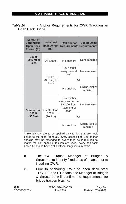
GO TRANSIT TRACK STANDARDS
TRACK STANDARDS Page 9-4 RC-0506-02TRK June 2016 Revised: 2016-04-20
Table 16 - Anchor Requirements for CWR Track on an
Open Deck Bridge
Length of Continuous Open Deck Portion (ft.)
Individual
Span Length (ft.)
Rail Anchor Requirements
Sliding Joint Requirements
100 ft
(30.5 m) or Less
All Spans
No anchors
None required
Greater than 100 ft
(30.5 m)
100 ft (30.5 m) or
Less
Box anchor every second
tie* None required
Or
No anchors Sliding joint(s) required
Greater than 100 ft
(30.5 m)
Box anchor every second tie
for 100’ from fixed end of
span*
None required
Or
No anchors Sliding joint(s) required
* Box anchors are to be applied only to ties that are hook bolted to the span (generally every second tie). Box anchor spacing may be extended to every third tie if required to match the bolt spacing. If clips are used, every non-hook bolted tie should have a clip without longitudinal restrain.
b. The GO Transit Manager of Bridges & Structures to identify fixed ends of spans prior to installing CWR.
c. Prior to anchoring CWR on open deck steel TPG, TT, and DT spans, the Manager of Bridges & Structures will confirm the requirements for bridge traction bracing.
GO TRANSIT TRACK STANDARDS
TRACK STANDARDS Page 9-5 RC-0506-02TRK June 2016 Revised: 2016-04-20
d. Anchor requirements and pattern should be confirmed with the Manager of Bridges & Structures.
e. Box anchor every tie for a minimum of 200 ft (61 m) off each end of open deck portion.
f. On timber span bridges, only box anchor the ties that are attached to the span with boat spikes, usually every other tie or as directed by the Rail Corridors Senior Manager of Track and Structures.
g. Movable spans will be anchored as directed by the Rail Corridors Senior Manager of Track and Structures.
h. Where elastic fasteners provide longitudinal restraint, they will be considered equivalent to anchoring.
17. CWR installed on a ballast deck bridge or span will be box anchored a minimum of every second tie.
9.3. Derails
1. Derails must be installed: a. Where there is any possibility of equipment that
has been left standing on tracks other than main tracks or sidings, may be moved by gravity so as to obstruct a main track or siding;
b. At tracks used to tie up locomotives on a regular basis. Through tracks so used must be equipped with derails at both ends. Locations used to tie up power will be specified by the GO Operations Division;
c. At entrances and exits of Main and Running Repair Shops. Derail must be applied to each track not less than 40 feet from doors. Where further safety measures are required, a derail pit may be installed in accordance with drawing CN Standard Plan TS-2212;
d. On tracks on which an industry will move cars or equipment, and
GO TRANSIT TRACK STANDARDS
TRACK STANDARDS Page 9-6 RC-0506-02TRK June 2016 Revised: 2016-04-20
e. On mining and other bulk loading facility tracks where cars are dropped by gravity toward the main or other track that is to be protected;
2. Derails shall only be installed or removed as directed by the Rail Corridors Senior Manager of Track and Structures or designate.
3. Rail Operations must advise the Rail Corridors Senior Manager of Track and Structures of all operational changes in writing. The Rail Corridors Senior Manager of Track and Structures will confirm whether or not said operational changes require the installation of additional derails and that adequate operating procedures are in place to protect the situation. Whenever operational changes so dictate, the Rail Corridors Senior Manager of Track and Structures must ensure that derails are installed in accordance with 9.3.1.
4. Whenever new tracks are designed or constructed, the Rail Corridors Senior Manager of Track and Structures must determine if a derail is required in accordance with Track Standards Section 9.3. Rail Corridors Senior Manager of Track and Structures must ensure that required derails are installed prior to placing the track in service.
5. Consideration for the removal of derails will occur only upon written request from Rail Operations to the Rail Corridors Senior Manager of Track and Structures, with a copy to the Director of Rail Corridors. The written request must include: a. Details of proposed operating conditions that will
ensure protection from unattended movements; b. Confirmation that these operating conditions are
in place; and where necessary, operating simulations may have to be carried out to confirm that the derail is no longer required.
6. Only the following approved types of derails are to be installed: a. Hinge Type Derail, Hayes Model EB, drawing
CN Standard Plan TS-2208

GO TRANSIT TRACK STANDARDS
TRACK STANDARDS Page 9-7 RC-0506-02TRK June 2016 Revised: 2016-04-20
b. Sliding Type Derail, Hayes Model HB, drawing CN Standard Plan TS-2209
c. Switch Point Derail, drawing CN Standard Plan TS-2210
d. Western Cullen Hayes bi-directional derail models SAEBX and HBXS
e. Portable derail, Hayes Model TS, is approved for use under CROR Rule 841.
7. Older type Hayes cast derails of type A, AP, G, GP and D are not to be used.
8. Power operated derails shall be installed and maintained in accordance with plans and instructions provided by the Rail Corridors Signals and Communications department.
9. The Rail Corridors Senior Manager of Track and Structures will approve the derail selection for each installation.
10. To eliminate the possibility of cars running over hinge and sliding derails without derailing, they must be the proper model, size and hand (eg. right or left hand) to fit the running rail. a. A right-handed derail is installed on the right-
hand rail and derails towards the right. b. A left-handed derail is installed on the left-
handed rail and derails towards the left. 11. In the derailing position the derail block must cover the
ball of the rail and lie flat on the top of the rail throughout the underside of the derailing block surface and will bear directly on sound ties.
12. The direction of movement of a car to be derailed determines whether a right or left-hand derail is required. A right-hand derail is installed on the right-hand rail and derails toward the right; a left-hand derail is installed on the left-hand rail and derail toward the left.
13. The correct size of derail to be used on various rail sections is as follows: a. Size 6: 100 ARA & 115 RE

GO TRANSIT TRACK STANDARDS
TRACK STANDARDS Page 9-8 RC-0506-02TRK June 2016 Revised: 2016-04-20
b. Size 7: 115 RE and larger c. On worn 115 RE rail a Size 6 derail should be
used. 14. A plywood or steel shim of the correct thickness with
holes punched or drilled for all fasteners may be necessary under the derail to ensure the block lies flat on the top of the rail. Where 2 inch (50 mm) plywood shims or extender/elevator plates are used, tie screws 1 inch (25 mm) longer shall be used.
15. If the rail at the derail location is replaced, the derail should also be replaced with one of the correct size for the rail. It is also possible to order steel Extender / Elevator plates from Western-Cullen-Hayes to raise the derail as follows: a. 1 inch (25 mm) spacer Part no. 21001-01 b. 2 inch (25 mm) spacer Part no. 21001-02
16. Operating stands of a rigid type (for example 31B, 36D or 112E) must be used with switch point derails. Rigid stands or Hayes operating stands must be used with sliding type derails. All derails designated as Special Derails in Special Instructions must be switch stand operated.
17. Throw of switch point type derails is 5 inches (127 mm). 18. Throw of sliding type derails is 6¼ inches (159 mm) 19. Hinge and sliding derails must be painted yellow. 20. All derails not equipped with high operating stands shall
have a derail sign in accordance with drawing TS plan 720 mounted on a separate post, as shown in CN Standard Plan TS-2208.
21. All derails equipped with high operating stands shall have a derail switch target in accordance with CN Standard Plan TS-720 mounted on the mast of the operating stand, as shown in CN Standard Plan TS-2209 and TS-2210.
22. Derails designated as Special Derails in Special Instructions shall have a special derail target installed in place of the standard derail target in accordance with drawing CN Standard Plan TS-720.

GO TRANSIT TRACK STANDARDS
TRACK STANDARDS Page 9-9 RC-0506-02TRK June 2016 Revised: 2016-04-20
23. When derail signs are mounted on the mast of high operating stands, they shall be attached to the mast so that they are visible when in the derailing position.
24. When directed by Special Instructions, derails protected by signals (or otherwise marked), will not require derail signs.
25. Targets and target tips, whether reflectorized or not, shall not be used in connection with derails.
26. Tracks equipped with a derail shall have the switch stand lever painted yellow.
27. Location for a derail is governed by local conditions such as grade and length of track, but when practicable should never be located less than 20 feet (6.1 m) behind the fouling point and installed so as to derail cars away from the track being protected. Sufficient distance should be allowed so that the derailed car cannot continue to move and foul the track being protected.
28. When the derail must be located close to the clearance point, a “bent type guard rail” must be installed between the rails, as shown on CN Standard Plan TS-2208, TS-2209 and TS-2210, to provide additional assurance that the derailed equipment will not foul the track being protected.
29. Derails should not be installed on the inside of curves if it can be avoided. If necessary to install a hinge type or sliding type derail on the inside of a curve, a derail wheel crowder must be installed on the outside rail on the same ties.
30. Where there are insulated joints, derails must be placed far enough behind the insulated joints so that equipment derails before fouling the track circuit.
31. The Rail Corridors Senior Manager of Track and Structures will specify where guard rails are to be used. Installations must be in accordance with Track Standard plan.
32. Straight guard rails will be required where the derailing point is: a. On a high embankment;

GO TRANSIT TRACK STANDARDS
TRACK STANDARDS Page 9-10 RC-0506-02TRK June 2016 Revised: 2016-04-20
b. Near structures that could be struck by derailed equipment; or
c. On a sharp curve. d. Refer to CN Standard plans TS-2208, TS-2209
and TS-2210 for details. 33. Derails, except those pipe connected to a switch stand,
must be equipped with an approved switch lock that is chained to the derail or the derail operating stand.
34. Derails and locks must be kept lubricated and adjusted to maintain ease of movement.
35. Ties to which derails are fastened must be sound and well tamped, and have the top surfaces in the same plane. Hardwood ties should be used whenever practicable.
36. Sliding and hinge derails must be installed at right angles to the rail. In new installations, the derail should be fastened to the ties with 1 inch x 6½ inch (25 mm x 165 mm) lag screws as per CN Standard plan TS 1315.
37. Derails must be fastened with all available holes. 38. An interlocked derail must not be disconnected or
adjusted until the Signal Maintainer has been notified. 39. Derails must be inspected by the Track Supervisor,
Assistant Track Supervisor or other qualified track inspector per the frequency defined in Appendix A – Track inspection frequencies in Table 37 a. Particular attention should be paid to tie,
spike/screw, and ballast conditions. b. Check for any distortion, fractures, damage from
derailments or accidents, or unusual wear on the derail.
40. To prevent hinge derails from freezing to the top of the running rail, a narrow weld bead may be added to the underside of the derail body at the rail centre line.
41. A handle may be welded onto the body of a hinge derail to make operating the derail easier.
42. Distances are calculated using TPC simulation program with a 263,000 lbs. car (GO locomotive). This chart is

GO TRANSIT TRACK STANDARDS
TRACK STANDARDS Page 9-11 RC-0506-02TRK June 2016 Revised: 2016-04-20
intended to be used as a guideline to assist field personnel in determining the proper derail for a specific location.
Table 17 - Guideline for Selection of Derail Type
Distance in which a Free-Rolling Car will achieve the following speed:
ft. (m) Gradient
(%)
8 mph
9 mph
12 mph
15 mph
0.30 1000 (305)
1280 (390)
2350 (716)
3800 (1158)
0.50 485 (148)
615 (187)
1125 (343)
1805 (550)
0.75 310 (95)
395 (120)
700 (213)
1090 (332)
1.00 225 (68)
285 (87)
555 (169)
785 (239)
1.50 155 (47)
190 (58)
330 (101)
510 (155)
2.00 115 (35)
140 (43)
245 (75)
380 (116)
43. Hinge and sliding derails may be installed where the
speed of equipment to be derailed will not exceed 15 mph.
44. On industrial track a wheel crowder will be installed when: a. A car mover is in use; or b. Equipment speed could exceed 10 mph.
45. On industrial track a switch point derail will be installed when: a. The speed of the equipment to be derailed could
exceed 15 mph; b. A private locomotive is in use;

GO TRANSIT TRACK STANDARDS
TRACK STANDARDS Page 9-12 RC-0506-02TRK June 2016 Revised: 2016-04-20
9.4. Track Spikes
1. Each rail shall be spiked as per the appropriate spiking pattern in Appendix P – Spiking Patterns.
2. Drive spikes vertically with the face of the spike in contact with the base edge of the rail, except spikes against insulated joints, which will be installed with heads turned away from the joint bar and not in solid contact with the joint bar. No fastenings may be installed at insulated joints in a manner that may short circuit the track circuit.
3. Spikes must be driven to a depth such that the spike head is within 3/16” (5 mm) of top of the rail base. Every effort should be made not to overdrive spikes.
4. Spikes will be driven only with a standard spike maul, pneumatic or hydraulic spiking hammer or spiking machine.
5. Spikes will not be driven within 2 in (50 mm) of the end of, or in the slots of, skirted (slotted) joint bars.
6. When pulling spikes, a spike lifter will be used when spikes cannot be loosened with a claw bar.
7. Spikes between the running rail and guard rails, as well as spikes in tight areas around heel blocks and frogs will be removed using a four-ball spike puller and claw-bar.
8. Claw bars will not be struck with mauls or other tools. 9. Turnouts shall be spiked as per the pattern identified in
Figure 11.
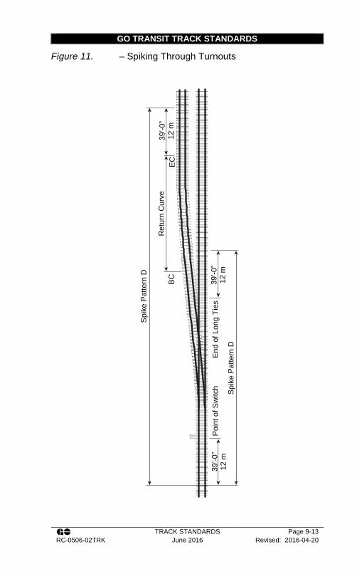
GO TRANSIT TRACK STANDARDS
TRACK STANDARDS Page 9-13 RC-0506-02TRK June 2016 Revised: 2016-04-20
Figure 11. – Spiking Through Turnouts
39’-0
” 12
m
Poi
nt o
f Sw
itch Spi
ke P
atte
rn D
39’-0
” 12
m
39’-0
” 12
m
Ret
urn
Cur
ve
Spi
ke P
atte
rn D
BC
E
C
End
of L
ong
Ties
GO TRANSIT TRACK STANDARDS
TRACK STANDARDS Page 9-14 RC-0506-02TRK June 2016 Revised: 2016-04-20
9.5. Timber Lag Bolts (Timber Screws)
1. Timber screw installation will require a 5/8 in (16 mm). pilot hole drilled a minimum 5 in (127 mm) into the tie.
2. Timber screws will be run (turned) into tie and not driven. 3. Timber screws will be used without washers.
9.6. Elastic Clips
1. Pandrol e2055 clips are used on wood tie turnouts and wooden track ties with elastic fastener plates.
2. Care must be taken to drive the clips correctly a. On concrete ties the “e” clips should be driven
so that the leg is flush with the shoulder b. On turnout plates on timber ties, clips must be
driven flush with the shoulder c. On pandrol plates clips will be driven so that the
radius in the clips does not contact the plate 3. Where clips are installed by hand, care must be taken
not to strike the shoulder or tie with the striking tool. 4. Where clips are installed by machine, the operator must
ensure that the machine is adjusted to insert the clip horizontally into the hole without binding.

GO TRANSIT TRACK STANDARDS
TRACK STANDARDS Page 10-1 RC-0506-02TRK June 2016 Revised: 2016-04-20
Section 10 - Ballast
10.1. Ballast Conditions
1. Track must be supported by material which will promote drainage of the track structure, and restrain the track laterally and vertically under dynamic loads imposed by railroad equipment and thermal stress exerted by the rails.
2. Ballast must conform to the appropriate GO Transit Crushed Rock Track Ballast Specification.
10.2. Ballasting
1. Ballast cross sections for new construction shall conform to CN Standard Plan TS-2205.
2. For the unloading of track ballast using railcars or hi-rail trucks, Recommended Method 3706-2: Ballast Unloading shall be followed.
3. Ballast cross section shall have: a. Cribs filled to a minimum of 1 inch (25 mm)
below the top of tie (except concrete ties). b. No ballast left on top of ties, spikes and tie
plates. c. Shoulder ballast for jointed rail to be maintained
to a minimum of 6 inches (152 mm) out from the end of the tie before sloping.
d. Shoulder ballast for CWR track should be maintained to a minimum of 12 inches (305 mm) out from the end of the tie before sloping.
e. On double main track and between main and siding tracks, a ballast trough between tracks should be maintained.
4. Ample clearance for rolling stock shall be provided when distributing and dressing ballast. Remove ballast from switches or flange-ways through frogs, guardrails and
GO TRANSIT TRACK STANDARDS
TRACK STANDARDS Page 10-2 RC-0506-02TRK June 2016 Revised: 2016-04-20
road and rail crossings at grade, which will impede proper operation or passage of wheel flanges.
5. When unloading ballast, only the amount of ballast required should be unloaded and in the correct location in order to reduce wasting ballast. Extra care should be taken when unloading near open deck bridges or road crossings. Car doors should be closed prior to any movement across open deck bridges. Ballast shall not be allowed to accumulate on road crossings.
6. When unloading ballast in the centre of the track, a plow tie may be used in order to evenly spread ballast and prevent excessive rock from accumulating on the rail and possibly derailing cars.
7. Remove any windrowed ballast such that it does not extend more than 2½ in (63 mm) above the top of rail. This will prevent damage to the equipment on the IRIS test trucks.
8. When unloading ballast, all cars must be completely empty and doors closed and locked prior to releasing.
9. Care must be exercised when unloading ballast from cars on one side or on curves with super-elevation. Prior to movement, the load should be inspected and levelled, as required.
10. The typical ballast profiles can be found in Appendix R – Typical Ballast Profiles, for CWR and jointed rail on concrete and timber ties
10.3. Clearances
1. For any work which will reduce the allowable clearances, such as ballast stockpiling, permission must be obtained from the Rail Corridors Manager of Track
2. Any lifts or realignment that may affect clearances to adjacent or overhead structures must receive prior approval from the Rail Corridors Senior Manager of Track and Structures, and when warranted, operational bulletins issued restricting train movements.
GO TRANSIT TRACK STANDARDS
TRACK STANDARDS Page 10-3 RC-0506-02TRK June 2016 Revised: 2016-04-20
10.4. Bridges
1. If bridges are within the section of track planned for re-ballasting, plans must be made to undercut each bridge approach for a sufficient distance to permit a safe and smooth runoff.
2. Ballast on train crew walkways is to be removed to avoid a tripping hazard and to protect the safe passage of the public and traffic under the bridge.
3. Provide from the end of the train crew walkway a well graded transition zone to the roadbed shoulder
4. On ballast deck bridges, provide temporary barriers to protect the public and traffic from falling ballast, during ballasting operations.
10.5. Public Crossings
1. At public crossings, re-ballasting must be done without risk or major inconvenience to the public. Well in advance of the planned work, advise the road authority of the nature and extent of the work to be done. Arrange for the installation of barricades, warning lights, and other safety devices to protect people and vehicles from using the crossing.
10.6. Undercutting
1. Take all necessary precautions to avoid track buckling. Pay close attention to the temperature when planning to use under-track plows, sleds, and other specialized undercutting equipment. Fill cribs and restore shoulders with new ballast as soon as possible.
2. The transitions or runoff off gradients must be made on tangent track and must be fully tamped and level to provide a smooth transition from newly ballasted track to old ballast. In no case can the rate of runoff be more than described in Track Standard Section 15.2.
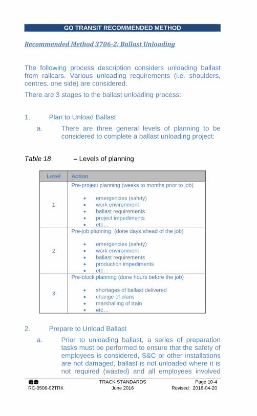
GO TRANSIT RECOMMENDED METHOD
TRACK STANDARDS Page 10-4 RC-0506-02TRK June 2016 Revised: 2016-04-20
Recommended Method 3706-2: Ballast Unloading
The following process description considers unloading ballast from railcars. Various unloading requirements (i.e. shoulders, centres, one side) are considered. There are 3 stages to the ballast unloading process: 1. Plan to Unload Ballast
a. There are three general levels of planning to be considered to complete a ballast unloading project:
Table 18 – Levels of planning
Level Action
1
Pre-project planning (weeks to months prior to job)
• emergencies (safety) • work environment • ballast requirements • project impediments • etc…
2
Pre-job planning (done days ahead of the job)
• emergencies (safety) • work environment • ballast requirements • production impediments • etc…
3
Pre-block planning (done hours before the job)
• shortages of ballast delivered • change of plans • marshalling of train • etc…
2. Prepare to Unload Ballast
a. Prior to unloading ballast, a series of preparation tasks must be performed to ensure that the safety of employees is considered, S&C or other installations are not damaged, ballast is not unloaded where it is not required (wasted) and all employees involved

GO TRANSIT RECOMMENDED METHOD
TRACK STANDARDS Page 10-5 RC-0506-02TRK June 2016 Revised: 2016-04-20
including the train crew are familiar with the locations and unloading procedures.
Step Action
1 Ensure unloading employees are provided with proper breathing apparatus
2 Provide train crew with list of unloading sites (should be pre-marked in the field)
3
Ensure that there is enough ballast on hand to completed the proposed work. If enough ballast is unavailable, prioritize where unloading will be done.
4
Job briefing by the unloading foreman, including: • locations and how much ballast will be unloaded at
each • obstructions • direction of unloading • whether you will be unloading centres, shoulders,
or both • speed of unloading • signals for shaking cars • where employees will meet to leave the site of clear
trains. • etc.
note: this should be done at each unloading site
5
Job briefing by train crew, including: • the time available to unload ballast • where trains will be cleared • how track gradients may affect unloading process • etc.
Note: this should be done at every unloading site
3. Unloading Ballast The following is a general outline to follow when unloading ballast from railcars.
Step Action
1 Ensure proper unloading bars/cranks available for old/new cars Crack doors on Morrison/Knudsen ballast cars
2
Move ballast train into position ensuring that train is marshalled so that:
• same car types are marshalled (should be done prior to obtaining work block)
• only loaded cars will move over flooded track • spreader is next to unit and train is “pushed” during
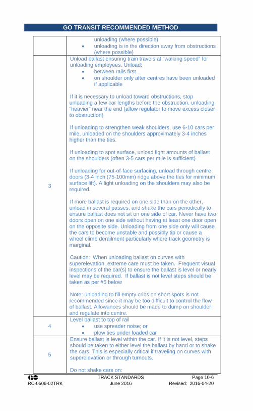
GO TRANSIT RECOMMENDED METHOD
TRACK STANDARDS Page 10-6 RC-0506-02TRK June 2016 Revised: 2016-04-20
unloading (where possible) • unloading is in the direction away from obstructions
(where possible)
3
Unload ballast ensuring train travels at “walking speed” for unloading employees. Unload:
• between rails first • on shoulder only after centres have been unloaded
if applicable
If it is necessary to unload toward obstructions, stop unloading a few car lengths before the obstruction, unloading “heavier” near the end (allow regulator to move excess closer to obstruction) If unloading to strengthen weak shoulders, use 6-10 cars per mile, unloaded on the shoulders approximately 3-4 inches higher than the ties. If unloading to spot surface, unload light amounts of ballast on the shoulders (often 3-5 cars per mile is sufficient) If unloading for out-of-face surfacing, unload through centre doors (3-4 inch (75-100mm) ridge above the ties for minimum surface lift). A light unloading on the shoulders may also be required. If more ballast is required on one side than on the other, unload in several passes, and shake the cars periodically to ensure ballast does not sit on one side of car. Never have two doors open on one side without having at least one door open on the opposite side. Unloading from one side only will cause the cars to become unstable and possibly tip or cause a wheel climb derailment particularly where track geometry is marginal. Caution: When unloading ballast on curves with superelevation, extreme care must be taken. Frequent visual inspections of the car(s) to ensure the ballast is level or nearly level may be required. If ballast is not level steps should be taken as per #5 below Note: unloading to fill empty cribs on short spots is not recommended since it may be too difficult to control the flow of ballast. Allowances should be made to dump on shoulder and regulate into centre.
4 Level ballast to top of rail
• use spreader noise; or • plow ties under loaded car
5
Ensure ballast is level within the car. If it is not level, steps should be taken to either level the ballast by hand or to shake the cars. This is especially critical if traveling on curves with superelevation or through turnouts. Do not shake cars on:

GO TRANSIT RECOMMENDED METHOD
TRACK STANDARDS Page 10-7 RC-0506-02TRK June 2016 Revised: 2016-04-20
• flooded track • open deck bridges • turnouts, especially in switch area • road crossings • skeletonized track
6
When finished unloading, close ballast car doors If using older enterprise cars, clean all ballast off centre doors and close them, then clean side doors prior to closing. Using Morrison-Knudsen, close chute and engage
7 Clean any switches , road crossings, railway crossings at grade, flange-ways, etc. that may be affected by ballast

GO TRANSIT TRACK STANDARDS
TRACK STANDARDS Page 11-1 RC-0506-02TRK June 2016 Revised: 2016-04-20
Section 11 - Surfacing and Lining
11.1. Surfacing and Lining
1. Do not lift track more than is necessary to maintain proper surface.
2. When track is lifted during surfacing operations, do not allow the rate of change in surface, (e.g. the rate of runoff), to be more than specified in Track Standard Section 15.2.
3. Special attention is to be given to the surface and line of track at approaches to bridges, culverts, switches, diamonds, road crossings, and through tunnels.
4. During surfacing work, employees must check the surface using a track level.
5. Any anchors removed must be replaced, anchors adjusted, missing elastic fasteners replaced, high spikes plugged and re-driven, and hanging ties brought up tight to the rail base. After all work is completed, employees should check for missing clips.
6. On completion of surfacing, the surface must be in compliance with Track Standard Section 15.2.
7. When tamping, only 16 in (406 mm) on either side of the rail is to be tamped.
8. Except at locations where steel ties are in use, the centre of the tie must not be tamped. (This is to prevent centre bound ties)
9. When tamping transition ties, the entire length of the tie outside the rail must be tamped. Steel ties must be tamped as per the manufacturer’s recommendations.
10. Track raises in excess of 6 in. (152 mm) should be avoided, however, if it is necessary, such lifts should be carried out successively so that individual lifts do not exceed 3 inches (76 mm). Dynamic stabilizers should be used between lifts.
GO TRANSIT TRACK STANDARDS
TRACK STANDARDS Page 11-2 RC-0506-02TRK June 2016 Revised: 2016-04-20
11. Spring frogs should not be tamped without jacks set on the side opposite tamper to help prevent tamper from bending the base plate.
12. When surfacing through spring frogs, care must be taken to ensure no lifting action is applied to any part of the moveable wing rail or frog plate.
13. When regulating through a spring frog the frog must be inspected on foot and cleaned to ensure there are no obstructions in both flange-ways and the wing rail is lubricated and free to move.
14. Track surfacing and lining which eliminates long line swings or lines curves to the inside may generate additional rail and should when practicable be monitored to determine if adjustment is needed.
15. When surfacing CWR track, the rail temperature must be monitored.
16. When rail has been added or the track lined inwards within 400 feet (122 m) of a high risk location listed in Track Standard Section 11.2 AND the rail temperature is above the PRLT, the precautions in Track Standard Section 11.3 must be followed.
17. When surfacing operations affect signal related track components, the Rail Corridors Signal Department must be notified in order to perform needed adjustments, repairs or inspections.
18. When surfacing around insulated joints, switch machines, crossing protection equipment, or other signal devices, care must be taken to prevent damage to bond wires, conduits, or other signal connections to the track. Particular attention is to be given to Hotbox Equipment, Dragging Equipment, and Wheel Impact Load Detectors.
19. Ensure that the surfacing broom and regulating operations do not damage adjacent property especially at highway underpasses and pedestrian walkways.
20. Whenever it is necessary to disturb the ballast to permit surfacing and lining, whether it is manual or mechanical, the ballast shoulder must be restored and the ballast cribs must be filled before returning track back to train service.

GO TRANSIT TRACK STANDARDS
TRACK STANDARDS Page 11-3 RC-0506-02TRK June 2016 Revised: 2016-04-20
11.2. High Risk Locations and Clearances
1. Examples of high risk locations are as follows: a. Bottom of a grade near a fixed track location
such as a bridge, turnout, road crossing or diamond
b. Known areas of heavy train braking at or near fixed track locations
c. Areas of insufficient anchors (non-compliant to the GO Transit Track Standards)
d. Fixed track locations within a directional running zone
e. Any areas showing signs of high rail compression
2. When surfacing or lining track where overhead or lateral clearances are involved (e.g. at tunnels, snow sheds, approaches to the ends of bridges, alongside signals, fueling stations, and platforms), the general level of the track, its alignment, its curve elevation, and its distance from adjacent tracks must not be changed without the authority of the Rail Corridors Senior Manager of Track and Structures.
3. Where permanent reference points are situated to indicate the location and elevation of the tracks (e.g. tunnels) they must be adhered to.
4. Particular attention must be paid to tracks adjacent to station platforms where the Metrolinx Design Requirement Manual (DRM) elevations between top of rail and top of platform, gauge face of rail and edge of platform measurements are provided.
5. Section 22 -1.Table 33 summarizes the requirements for station platforms. In the case of discrepancies between the Track Standards and the DRM with respect to platform clearances, the DRM governs.
11.3. Precautions
1. If possible, surface away from the fixed location and not towards it.

GO TRANSIT TRACK STANDARDS
TRACK STANDARDS Page 11-4 RC-0506-02TRK June 2016 Revised: 2016-04-20
2. If not possible, cut the rail and ensure a desirable rail stress-free temperature.
3. Before surfacing and lining a curve on main tracks, the curve must be staked if it is more than 3° and the rail temperature is more than 50°F (28°C) below the preferred rail laying temperature, or is expected to be in the next 24 hours.
4. To stake a curve prior to surfacing and lining, place at least 3 reference stakes uniformly spaced around the curve with the middle stake located near the middle of the curve. Additional stakes may be used due to the overall length of the curve.
5. Inspect for curve movement periodically after the work, especially during periods of large temperature changes. If the curve is found to have shifted inward more than 1 inch, it must be lined out or destressed prior to ambient temperature reaching 70° F (21°C). If the curve is not lined out or destressed then a speed restriction must be placed per Track Standard Section 3.6. The effective rail length added to a curve as a result of chording inwards is calculated in Appendix K – Effective Length Added For Curves Chording Inward.
6. After surfacing, track seen to exhibit signs that CWR is out of adjustment shall be reported to the Track Supervisor and the track protected until remedial action is taken.
7. Turnouts in CWR mainline will not be surfaced with a tamper unless anchor pattern meets Track Standards.
11.4. Surfacing Concrete and Steel Ties
1. The surfacing and lining of concrete ties should follow the same procedure as that for timber ties.
2. For tamping steel ties: a. Crib shoulders must be full to ensure sufficient
ballast is available for tamping b. Inspection holes are located on either side of the
rail seats to ensure the tie pods are full
GO TRANSIT TRACK STANDARDS
TRACK STANDARDS Page 11-5 RC-0506-02TRK June 2016 Revised: 2016-04-20
c. Tamping tools must be raised to compensate for the depth of steel ties vs. wood ties. Steel ties are up to 2.5 inches (64 mm) shallower than wood ties.
d. Steel Ties must be centre tamped with the tampers traversing work heads
e. The tamping cycle should consist of at least two insertions at the rail seats and one in the centre of the tie to ensure proper compaction
f. When steel ties are interspersed with wood ties, two full surfacing passes should be made, with the first pass, surface the entire track in accordance with normal procedures, for the second pass, only tamp the steel ties, without lifting the track, always tamp the steel ties last.
g. Refer to the steel tie manufacturers, Narstco’s, Steel Tie and Turnout Set Assembly Instructions for tamping tool settings and further details.

GO TRANSIT TRACK STANDARDS
TRACK STANDARDS Page 12-1 RC-0506-02TRK June 2016 Revised: 2016-04-20
Section 12 - Installation and Maintenance of Turnouts
12.1. General
1. Care must be taken when working around turnouts to avoid interfering with Signal Systems:
2. Use extreme care not to short across an insulated gauge rod, insulated gauge plate or insulated joints when using any tool that conducts electricity, such as: track wrench, shovel, ballast fork, tie tongs or metal broom.
3. At locations where snow-clearing devices are installed, use extra precautions. There is the possibility of creating a short circuit through the metal ductwork.
4. Responsibility for lubrication of switch point plates at any particular location will be assigned by the Rail Corridors Manager of Track.
5. New spring frogs are not allowed on GO Transit / Metrolinx owned territory unless so authorized by the Rail Corridors Senior Manager of Track and Structures in writing.
12.2. Installation of Turnouts
1. Each newly constructed turnout must have a detailed inspection by the Track Supervisor and a Rail Corridors Representative before it is placed into service, or a 10mph speed restriction will apply. See 0
2. Do not reuse non-premium components (eg. points that are not FHH) on any turnout on the core route that is 115 RE or greater in weight.
3. Turnouts must not be installed or renewed on main track curves, except in special cases as authorized by the Rail Corridors Senior Manager of Track and Structures.
4. Power, Dual Control, Spring and Electrically Locked switches shall be installed only at locations approved by
GO TRANSIT TRACK STANDARDS
TRACK STANDARDS Page 12-2 RC-0506-02TRK June 2016 Revised: 2016-04-20
the Rail Corridors Senior Manager of Track and Structures.
5. When turnouts are delivered prefabricated and in panel cars, the following precautions will be taken when unloading and transporting: a. Panel turnouts must be completely secured to
the racks of the cars whenever the car is moved. b. The weight of each panel must be known and
compared to the load chart of the crane prior to attempting a lift.
c. Each panel in the car will be fully secured until it is ready to be lifted from the car. The panel will only be released once the crane lift lines are secured to the panel.
d. Removal of panel tie-down chains will be done from behind the turnout panel.
e. No one is allowed in a panel turnout car when the panel is being lifted.
f. Panels will be placed where they will not affect the safety of railroad operations or the public.
g. All tie-down chains must be placed in the car when the car is empty.
6. When turnouts are being constructed, trains should not be permitted to move in either direction until: a. The frog is properly protected by a guard rail;
and b. The main track switch point is clamped or lined
and locked against the stock rail. 7. Switch stands should be plumb and be securely spiked,
bolted or lagged to the head block ties. Stands on spring switches shall be securely bolted to the head block ties.
8. Main track switch stands shall be of an approved rigid type
9. Semi-automatic stands of an approved type (22E) may be used on yard tracks only.
10. Throw is critical on type 22 switch stands. Please ensure that they match the values in Table 19.

GO TRANSIT TRACK STANDARDS
TRACK STANDARDS Page 12-3 RC-0506-02TRK June 2016 Revised: 2016-04-20
Table 19 – Throw for Type 22 Switch Stands
Throw Crank Eye Adjustment ± 1/32” (0.8 mm) ± 1/16” (1.6 mm) 4½” (114 mm) 2-1/16” (52 mm)
4-5/8” (117 mm) 2-3/16” (56 mm) 4¾” (121 mm) 2¼” (57 mm)
4-7/8” (124 mm) 2-5/16” (59 mm) 5” (127 mm) 2-7/16” (62 mm)
11. All main track stands must be equipped with an
approved switch lock in good working order and properly chained to the stand on high mast switch stand or to the ties on low mast switch stands. Switch stands on non-main tracks are to be equipped with a hook type keeper unless otherwise directed.
12. On ALL main track hand operated switches, regardless of the method used to control train operation, as well as within yard limits, high security switch locks must be installed. a. This applies to all dual control and power
switches, including self-restoring, locally controlled switches (LCS).
b. At locations where vandalism is a concern, high security switch locks may also be installed as directed by the Rail Corridors Manager of Track on the following. i. Hand operated switches on non-main
tracks ii. Other devices such as derails, electric
switch locks, foot pedals, push button operation panels, etc.
13. Switch rods and connecting rod bolts must be inserted with the nuts on the top side and secured with cotter pins. Ensure the connecting rod jaw openings, bolt holes and bolts correctly match the switch rods. The connecting rod bolt under the switch stand must be installed with the head of the bolt on the upper side.

GO TRANSIT TRACK STANDARDS
TRACK STANDARDS Page 12-4 RC-0506-02TRK June 2016 Revised: 2016-04-20
14. Where switch point locks are installed, the switch will be identified by painting the top of the switch stand castings white.
15. Switch points shall fit snugly against the stock rails for the entire length of the planed portion.
16. Turnout stock rails shall be horizontally bent as shown on the Standard Plan. The JB-60-141 is the only rail bender permitted to field bend stock rails of all metallurgy, for rail weights up to and including the 141 RE section. All other benders, without exception, are limited to bending 115 lb. or lighter rail in standard carbon and 3HB metallurgy only.
17. It is important that stock rails are properly seated in the switch plate, have no lateral movement in the plates and that switch plates have no movement on the ties. Care must be taken in adjusting braces to avoid over-driving and rotating the stock rails out of the rail seat of the plate.
18. When surfacing through a turnout with boltless adjustable rail braces, switch points and stock rails will be blocked to prevent displacement of the stock rail from the switch plate.
19. Switch point protectors or switch point guards of an approved type may be installed, to protect the switch point where the speed on any route through the turnout does not exceed 15 mph. Care must be taken when installing to ensure that the protector fits properly against the rail and that any flowed metal on the gauge side of the straight stock rail is ground off.
20. Ballast will be cleaned from cribs to a depth adequate to prevent contact with rods and to facilitate winter switch maintenance and drainage.
21. In CWR territory, when a turnout or new rail is installed during highway crossing rehabilitation the rail must be destressed. Track Standard Section 3.6 and Recommended Method 3205-2A: Destressing at Turnouts outlines the method to use to destress such a location.

GO TRANSIT TRACK STANDARDS
TRACK STANDARDS Page 12-5 RC-0506-02TRK June 2016 Revised: 2016-04-20
12.3. Destressing at Turnouts
1. Prior to cutting the rail, make reference marks on each rail at both the switch point end and the frog end of the existing turnout, where the track is to be cut for installation of the turnout. Measure and record the distance between these marks on the rail and on paper.
2. Cut and remove existing panel and install new. 3. Starting at the reference mark, match mark each rail
approximately every 50 ft. (15 m) for a distance of 400 ft. (122 m) beyond the point end and frog end of the turnout. Ensure that the match marks start on the web and extend across the base and onto a tie plate. Ensure that the match marks are made with paint stick pen and are straight.
4. Measure between your reference marks to see if any rail has been added.
5. All welds must be made before de-stressing the new turnout or road crossing.
6. Knock off the anchors on all rails behind the long ties for 400 ft. (122 m) at the frog end of the installed turnout. Measure the rail temperature. Half way through this unanchored stretch (about 200 feet – 61 m) cut the rail. Calculate the amount of rail to be removed by using the CWR Rail Adjustment Chart; Use a rail length of 500 feet regardless of the size of the turnout. Add to this amount any rail added when the panel was installed (see reference marks) and 1” (25 mm) for welding; this will be the amount of rail that will need to be removed. The distance to either heat or pull the rail with expanders at the frog end of the turnout will be this amount less the one inch for welding. If heat is used check match marks to insure expansion is throughout the 400 unanchored feet (122 m)
7. If reference marks are closer together, just use the adjusted requirement given in the Rail Adjustment Table.
8. Make the weld. After the weld has cooled, re-apply anchors to the 400 ft. (122 m) of rail behind the turnout that was previously de-anchored.
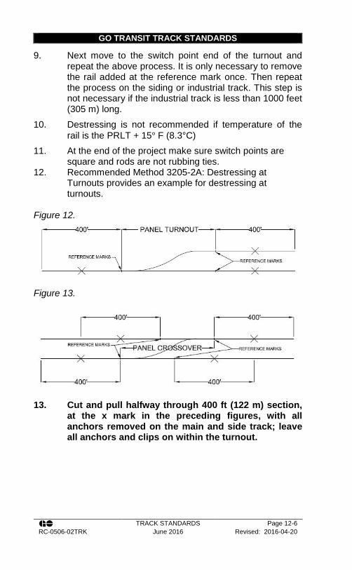
GO TRANSIT TRACK STANDARDS
TRACK STANDARDS Page 12-6 RC-0506-02TRK June 2016 Revised: 2016-04-20
9. Next move to the switch point end of the turnout and repeat the above process. It is only necessary to remove the rail added at the reference mark once. Then repeat the process on the siding or industrial track. This step is not necessary if the industrial track is less than 1000 feet (305 m) long.
10. Destressing is not recommended if temperature of the rail is the PRLT + 15° F (8.3°C)
11. At the end of the project make sure switch points are square and rods are not rubbing ties.
12. Recommended Method 3205-2A: Destressing at Turnouts provides an example for destressing at turnouts.
Figure 12.
Figure 13.
13. Cut and pull halfway through 400 ft (122 m) section,
at the x mark in the preceding figures, with all anchors removed on the main and side track; leave all anchors and clips on within the turnout.
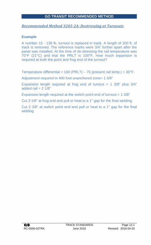
GO TRANSIT RECOMMENDED METHOD
TRACK STANDARDS Page 12-1 RC-0506-02TRK June 2016 Revised: 2016-04-20
Recommended Method 3205-2A: Destressing at Turnouts Example
A number 15 - 136 lb. turnout is replaced in track. A length of 200 ft. of track is removed. The reference marks were 3/4” further apart after the panel was installed. At the time of de-stressing the rail temperature was 70°F (21°C) and that the PRLT is 100°F. How much expansion is required at both the point and frog end of the turnout?
Temperature differential = 100 (PRLT) – 70 (present rail temp.) = 30°F.
Adjustment required in 400 foot unanchored zone= 1 3/8”
Expansion length required at frog end of turnout = 1 3/8” plus 3/4” added rail = 2 1/8”
Expansion length required at the switch point end of turnout = 1 3/8”
Cut 3 1/8” at frog end and pull or heat to a 1” gap for the final welding.
Cut 2 3/8” at switch point end and pull or heat to a 1” gap for the final welding


GO TRANSIT TRACK STANDARDS
TRACK STANDARDS Page 12-1 RC-0506-02TRK June 2016 Revised: 2016-04-20
12.4. Maintenance of Turnouts
1. The Signal Maintainer shall be present when any planned work, which may interfere with the functioning of the signal apparatus, is being performed.
2. Switch stands, switch plates, connecting rod bolts, and spring frogs shall be kept properly lubricated to provide easy movement and to protect against excessive wear.
3. Switch stands, targets, masts, connecting rods and all other component parts must be kept in good operating condition and must have defective parts repaired or replaced immediately.
4. The application of heat or mechanical methods to repair bent or twisted switch stand masts is not permitted.
5. Adjustment of semi-automatic switch stands shall be performed in accordance with Recommended Method 3200-6: Adjustment of #22 Switch Stands. Where inspection/adjustment reveals excessive wear or other internal problems with the stand, it must be removed from track.
6. Insulation in switch rods, pipe connected derails and gauge plates shall be maintained in good condition at all times.
7. Metal flow on switch points and stock rails shall be kept ground off to maintain proper gauge and to prevent chipping of these parts. Flow should not exceed 1/16” (1.5 mm) on switch point or gauge side of stock rail.
8. Welding of switch points is NOT permitted on any main line track.
9. Gaps in switch points, regardless of size, are unacceptable. The points must fit tightly against the stock rail.
10. Switch rods and transit clips should have sufficient clearance so as not to contact the side of the tie or the slide plate.
11. Good rail tie conditions must be maintained under the heel assembly.

GO TRANSIT TRACK STANDARDS
TRACK STANDARDS Page 12-2 RC-0506-02TRK June 2016 Revised: 2016-04-20
12. Self-guarded manganese frogs must not be used in track where speeds exceed 15 mph.
13. Once a frog has been installed, the manganese inserts shall be ground at the following suggested minimum intervals to remove flow and lip: a. After the passage of approximately 0.5 Million
Gross Tons (MGT) of traffic (approx. 725 10-car GO Trains);
b. After the passage of approximately 1.5 MGT of traffic (approx. 2,174 10-car GO Trains);
c. After the passage of approximately 4 MGT of traffic (approx. 5,800 10-car GO Trains); and
d. After every subsequent 12 MGT (approx. 17,400 10-car GO Trains) or as required to remove flow and lip.
14. All new special track-work 100 ARA or less will be assembled using grade 5 bolts. Grade 5 bolts can be identified by three (3) radial lines on the head of the bolt. The use of 100 ARA special track work MUST be approved by the Rail Corridors Senior Manager of Track and Structures.
15. All new special track-work 115 RE or greater will be assembled using grade 8 bolts. Grade 8 bolts have six (6) radial lines on the head of the bolt. Whenever grade 8 bolts are used, each bolt must be equipped with a hardened steel washer. 136 RE special track work is recommended in all new construction on GO Transit operated territory. All other weights of track shall be approved by the Rail Corridors Manager of Track.
Table 20 - Torque to be applied to Grade 5 Bolts for
Special Track Work
Size of Bolt 1“ (25 mm)
1-1/16” (27 mm)
1-1/8” (29 mm)
1¼” (32 mm)
Torque (ft-lbs) 670 850 1200 1600
Torque (N-m) 910 1150 1630 2170

GO TRANSIT TRACK STANDARDS
TRACK STANDARDS Page 12-3 RC-0506-02TRK June 2016 Revised: 2016-04-20
Table 21 – Torque to be Applied to Grade 8 Bolts for Special Track Work
Size of Bolt 1“ (25 mm)
1¼” (32 mm)
1-3/8” (35 mm)
Torque (ft-lbs) 840 1675 2500
Torque (N-m) 1140 2270 3390
16. See Recommended Method 3500-7: Switch Point Guard
Rail Adjustment for instructions on how to adjust switch point guard rails.
12.5. Maintenance of Spring Frogs
1. New spring frogs are not allowed on GO Transit / Metrolinx owned territory unless so authorized by the Rail Corridors Senior Manager of Track and Structures in writing.
2. Do not put any part of your body between the spring wing rail and the point rail unless the spring is securely blocked open.
3. Make sure the spike holes are plugged and the frog base plate is resting flat and solid. If not, adze or replace ties as necessary to provide a flat solid bottom under the entire frog. Make sure tie spacing is correct for the size of frog being installed.
4. Guard rails are extremely important. They provide protection and ensure the proper operation of the spring wing rail. Make sure the frog is properly gaged (56 ½ inches), and that the guard check gage and the guard face gage measurements are greater than or equal to the minimums shown by the class of track in the Transport Canada Track Safety Rules.
5. Care must be taken when lifting the frog with a tamper as the rail base hooks may bend the frog base plate. Hand jacks MUST be utilized on the outside rails of the turnout to assist in lifting the frog
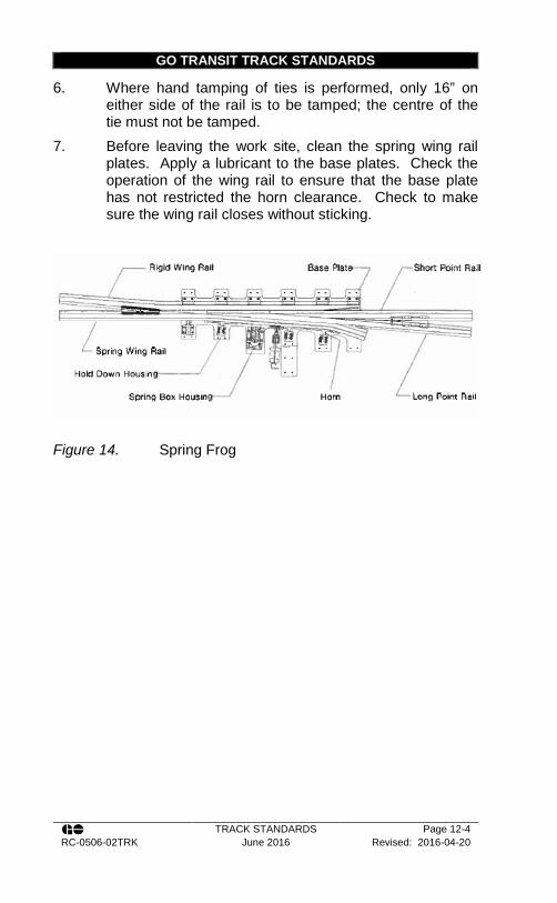
GO TRANSIT TRACK STANDARDS
TRACK STANDARDS Page 12-4 RC-0506-02TRK June 2016 Revised: 2016-04-20
6. Where hand tamping of ties is performed, only 16” on either side of the rail is to be tamped; the centre of the tie must not be tamped.
7. Before leaving the work site, clean the spring wing rail plates. Apply a lubricant to the base plates. Check the operation of the wing rail to ensure that the base plate has not restricted the horn clearance. Check to make sure the wing rail closes without sticking.
Figure 14. Spring Frog

GO TRANSIT RECOMMENDED METHOD
TRACK STANDARDS Page 12-1 RC-0506-02TRK June 2016 Revised: 2016-04-20
Recommended Method 3200-6: Adjustment of #22 Switch Stands
Switch stands can become “out of adjustment” for a variety of reasons. Wear of the switch components and internal wear of the switch stand are the main two reasons. The purpose of this RM is to give guidance on how to test and return a switch stand to proper adjustment. This RM covers the Racor 22B (base), 22P (pedestal), 22E (ergonomic) stands. The internal workings of these stands are identical, and only the pedestals, latches and handles differ. 1. Check the condition of the head block ties. If there is
evidence of loose spikes or stand is moving, the ties may be spike killed and it may be necessary to change the ties.
2. Adjust the throw of the switch to the dimension specified on standard plans.
3. It is likely you will not be able to get the throw of the switch to be exactly as in the standard plan because the teeth of the adjustment on the switch rods are fairly coarse. The throw must never be more than 5 1/32” (128mm) or less than 4 ½” (114mm).
4. When you are satisfied with the throw of the switch points, adjust the crank eye bolt setting in accordance with the 12.5.7.Figure 14.Table 22. These settings are critical to insure the stand will lock into place.
Table 22 – Crank Eye Bolt Settings
Throw ±1/32” (±0.8mm)
Crank Eye Adjustment ±1/16” (1.6mm)
4 ½” (114mm) 2 1/16” (52mm) 4 5/8” (117mm) 2 3/16” (55mm) 4 ¾” (121mm) 2 ¼” (57mm) 4 7/8” (124mm) 2 5/16” (59mm)
5” (127mm) 2 7/16” (62mm) 5. The crank eye adjustment is fairly coarse because the
crank eye can only be adjusted half a turn at a time. Do not set the crank eye bolt setting over 2-3/4” under any circumstances as the bolt will strike the housing of the

GO TRANSIT RECOMMENDED METHOD
TRACK STANDARDS Page 12-2 RC-0506-02TRK June 2016 Revised: 2016-04-20
stand and damage it. If you find the setting is over 2-3/4”, shorten it.
6. When you are satisfied that the crank eye bolt is set per the table, leave it alone. Also do not try to compensate for the inexactitude in the crank eye bolt setting by going back and changing the switch point throw. The throw is the master number to which everything else is adjusted.
7. Balance the throws left and right. a. The technique for adjustment is given in the
manufacturer’s instructions accompanying each Racor 22 Safety Switch Stand. Sections are quoted below:
i. Temporarily bolt connecting rod to the stand and head rod (clevis end of rod to crank eye), lift handle of stand to centre position; ensure the connecting rod is straight. Install the stand firmly to the ties using lag screws.
ii. Hand throw switch to both positions several times observing position of hand lever when points contact stock rail. Hand lever should not be more than 1-1/2” to 2” above the final position on top of foot latch rest for both positions.
iii. When the near point fits properly and the far point is too tight, shorten the crank-eye, and shorten the connecting rod clevis.
iv. When the near point fits properly and the far point is too loose, lengthen the crank-eye setting and lengthen the connecting rod clevis.
v. When the far point fits properly and the near point is too tight, shorten the crank-eye settings and shorten the connecting rod clevis.
vi. When the far point fits properly and the near point is too loose, lengthen crank-eye setting and lengthen the connecting rod clevis.
8. If all the foregoing adjustments were made as specified, see Track Standard Section 16.5, 16.6, and 16.6.8 for further details.

GO TRANSIT RECOMMENDED METHOD
TRACK STANDARDS Page 12-3 RC-0506-02TRK June 2016 Revised: 2016-04-20
Recommended Method 3500-7: Switch Point Guard Rail Adjustment
Switch point guards periodically require adjustment due to wear on the guard bar. The following procedures should be followed as to when and how to make the adjustments. Note: When making adjustments, ensure that the distance from the gauge side of the stock rail to the wear face of the switch point guard is never less than the initial installation dimension given for each type of switch point guard. Dimensions less than this could cause a wheel climb derailment. There are three types of point guards. The following describes the method to follow for adjustment: 1. Western Cullen Hayes FM series II Switch Point Guards:
a. When to Adjust: On a new installation the distance from the gauge side of the stock rail to the face of the wear bar is 3-15/16”. When this dimension measures between 4-3/16 to 4-1/4” the guard bar must be adjusted inwards.
b. How to Adjust: To adjust the guard bar, unbolt the 6 bolts that hold the adjustment inserts in place. Rotate the adjustment inserts so that the thicker side of the adjustment insert is closest to the stock rail and the narrower side of the adjustment insert is furthest away from the stock rail. Check that the distance from the gauge face of the stock rail is between 3-15/16” to 4-1/8”. If so rebolt the 6 bolts that hold the guard bar in place and recheck the stock rail to guard face dimension.
c. Note: The Western Cullen Hayes switch point guard only has 1 adjustment of 1/4“ each after the initial
GO TRANSIT RECOMMENDED METHOD
TRACK STANDARDS Page 12-4 RC-0506-02TRK June 2016 Revised: 2016-04-20
installation. Adjustment beyond that is not possible and a new wear bar will be required.
2. Nortrak Switch Point Guards a. When to Adjust:
On a new installation the distance from the gauge side of the stock rail to the face of the wear bar is 4”. When this dimension measures between 4-1/4” to 4-5/16” the guard bar must be adjusted inwards.
b. How to Adjust: To adjust the guard bar, unbolt the 3 bolts that hold the guard bar in place. There are adjustment holes offset¼” from the initial (centre) hole. Move the guard bar to the left or right depending on which adjustment is being made. Check that the distance from the gauge face of the stock rail is between 4” to 4-1/8”. If so re-bolt the 3 bolts that hold the guard bar in place and recheck the stock rail to guard face dimension.
c. Note: The older Nortrak switch point guards have 2 adjustments of 1/4” each after the initial installation. Adjustment beyond that is not possible and a new wear bar will be required. The newer switch point guards have a wear face on both sides of the wear plate and can be flipped to give a total of 6 positions of wear ( e.g. 6 – 1/4” adjustments).
3. Abex or ABC Rail Switch Point Guards a. When to Adjust:
On a new installation the distance from the gauge side of the stock rail to the face of the wear bar is 4”. When this dimension measures between 4-1/4” to 4-5/16” the guard bar must be adjusted inwards.
b. How to Adjust: To adjust the guard bar, unbolt the 2 nuts and washers that hold the guard bar in place (The bolts are welded to the top of the wear plate, so the nuts must be removed from the underside). There are adjustment holes offset ¼” from the initial (centre)

GO TRANSIT RECOMMENDED METHOD
TRACK STANDARDS Page 12-5 RC-0506-02TRK June 2016 Revised: 2016-04-20
hole. Lift and move the guard bar to the left or right depending on which adjustment is being made and insert bolts into these holes. Check that the distance from the gauge face of the stock rail is between 4” to 4-1/8”. If so rebolt the 2 bolts that hold the guard bar in place and recheck the stock rail to guard face dimension.
c. Note: The Abex or (ABR rail) switch point guards have 2 adjustments of 1/4” each after the initial installation. Adjustment beyond that is not possible and a new wear bar will be required.


GO TRANSIT TRACK STANDARDS
TRACK STANDARDS Page 13-1 RC-0506-02TRK June 2016 Revised: 2016-04-20
Section 13 - Crossings
13.1. At-Grade Rail Crossings (Diamonds)
1. For railway diamonds, follow the same procedure as for turnouts in Track Standards Section 12.2 and 12.3
2. Crossings will be installed according to the plans supplied for each crossing.
3. Avoid damage to crossing frogs when handling, placing and lifting. When necessary to use jacks on crossings, they should be applied to the frog proper, not to the arm rails.
4. Installation of guardrails in advance of the crossing will be at the discretion of the Rail Corridors Senior Manager of Track and Structures.
5. Subgrade under crossings must be well drained. Clean crushed rock ballast will be kept well tamped so that the surface of the frog is maintained at a uniform grade with the approaches. Only approved ballast shall be used. a. If the tread portion of a casting is worn down
more than 3/8” (10 mm) below the original contour (below level corners where diamond crossing corner pads have been ground off), operating speed over that crossing may not be more than 10 mph.
b. Crossings must be fully bolted. All bolts will be provided with spring washers or hardened steel flat washers as indicated on the manufacturer’s plan, and will be kept tightened to the torque shown in Table 20 and Table 21 of Track Standard Section 12.4.
6. Reversible crossing inserts may be transferred between corners to equalize wear.
7. Movable point crossings will be adequately lubricated with an approved lubricant.
8. Crossings will be kept free of snow, ice and other obstructions.
GO TRANSIT TRACK STANDARDS
TRACK STANDARDS Page 13-2 RC-0506-02TRK June 2016 Revised: 2016-04-20
9. Crossings ties will be sound and firmly tamped for the entire length of the tie on both routes of the crossing.
10. All crossings will be adequately protected at all times with spare components to ensure continued operation.
13.2. At-Grade Road Crossings
1. Before any maintenance or construction work can begin within a crossing or crossing approach protected by a road crossing warning system that may be affected by the work, the responsible S&C employee will be contacted and will protect the crossing according to prescribed S&C procedures. When the crossing is deactivated, the employees must have a clear understanding of the means of protection utilized to ensure trains do not operate unprotected over the crossing. In the event that this protection requires manual flagging, this protection shall not be removed until notified by the responsible S&C employee that the crossing has been reactivated.
2. Before any maintenance or construction work can begin on a crossing, advise road authorities and emergency services with as much advance notice as possible of anticipated traffic delays providing expected times and durations of closures. Plan for detours and other means to handle emergency situations if they should occur.
3. Crossings must comply with safety standards acceptable to Transport Canada.
4. Applications from outside parties for crossings should be directed to the Director of Rail Corridors who will ensure that all legal, financial, and other Railway requirements are met before a crossing is approved or constructed.
5. Crossing shall not be constructed, widened or relocated without prior approval of both the Director of Rail Corridors and Transport Canada.
6. When an agreement has been signed and filed for the construction of a new crossing, the track is to be prepared for the construction of the crossing and the installation of planking or crossing surface material as directed by the Rail Corridors Senior Manager of Track

GO TRANSIT TRACK STANDARDS
TRACK STANDARDS Page 13-3 RC-0506-02TRK June 2016 Revised: 2016-04-20
and Structures. Appendix T – Crossing Surfaces and Recommended Method 2700-0: Construction and Reconstruction of Grade Crossings in Wood and Concrete Tie Territories contains guidelines for the selection of crossing surface.
7. New private crossings must be covered by the Railway’s standard form of contract or license agreement before the crossing is constructed and put into service, unless the requesting party can satisfactorily demonstrate that they are otherwise entitled to a crossing under an applicable statute, deed covenant or other prescriptive right. In addition, private crossings must not be converted to public crossings except in accordance with applicable laws and regulations, and not until a formal agreement between the Railroad and the Public Authority accepting responsibility for the roadway has been signed and filed with the Metrolinx Legal Department.
8. The railway is responsible for the physical maintenance of the surface of the traveled roadway between the rails and for a distance of 18 inches (457 mm) outside of each rail for unrestricted/public crossings. However costs may be recoverable or shared as per Regulatory Order, formal agreement, or License Agreement.
9. All applicable signage (cross-bucks, whistle signs, etc.) should be installed in accordance with the Standard Plan. An emergency notification sign should be affixed to all of the signposts or signal masts or signal bungalows at unrestricted/public crossings and the signs should also show the exact milepost.
10. When an unrestricted/public crossing has been granted approval for the elimination of whistling, Prohibited Whistle (anti-whistling) Signs shall be installed in lieu of Whistle Signs and in accordance with the Standard Plan.
11. At-grade road crossings can be classified as either Unrestricted or Restricted crossings.
12. An Unrestricted Crossing is any crossing whose road is one of the following: a. A recreation road or trail maintained by a club,
association or other organization;
GO TRANSIT TRACK STANDARDS
TRACK STANDARDS Page 13-4 RC-0506-02TRK June 2016 Revised: 2016-04-20
b. A road of a commercial or industrial establishment, including a business operated from a residential or farm property, that is used in connection with the establishment by persons other than the employees of the establishment;
c. A road that serves three or more principal residences;
d. A road that serves three or more seasonal residences access to which is not controlled by a gate equipped with a lock;
e. A private road that connects two public roads; or f. A private road maintained by a natural resource
company, such as a company involved in forestry or mining activities;
13. A Restricted Crossing is any crossing that is not included in the above definition of an Unrestricted Crossing.
14. Private Agreement Crossings are crossings established under license-agreement between the Railway and an outside party must be covered by the Railway’s standard form of contract or agreement before the crossing is constructed and put into service.
15. The view in both directions for vehicles approaching the track shall be kept clear with vision clearance triangles in accordance with the Transport Canada Guideline G4-A shown in 13.3.40.Figure 16.
16. Rails, planking, spikes, etc. in crossings shall be checked periodically to make sure they do not present a hazard to the roadway or railway traffic. If a hazard exists, appropriate action must be taken to correct the condition.
17. Track surface, line and gauge at crossings shall be properly maintained.
18. Flange-ways at crossings should be kept clear of dirt, sand and ice and other obstructions.

GO TRANSIT TRACK STANDARDS
TRACK STANDARDS Page 13-5 RC-0506-02TRK June 2016 Revised: 2016-04-20
13.3. Construction of Roadway Crossings
1. Drainage is of primary importance to both the track and highway roadbed. The removal of water will aid in the stability of the subgrade and its ability to carry the applied loads. The use of perforated pipe parallel to the crossing must be considered during the design/planning process.
2. Surface ditches should be installed (or the existing ones cleaned out) so that water is directed away from the track at each quadrant. If this is not possible, subsurface drainage connected to a storm drainage system should be installed.
3. If the grade line of the roadway slopes towards the crossing, surface water should be intercepted prior to reaching the crossing and discharged laterally from the roadway. This can best be accomplished by the introducing of a slight swale in the roadway, prior to the crossing, with a crown in the road surface to aide in runoff.
4. This crown must be run out prior to reaching the crossing. If the roadway has curbs, then catch basins connected to a storm water system should installed.
5. Liaising with the road authority will be required to achieve the above.
6. On side hills where the roadway slopes towards the track and the road surface is unimproved (not paved) it is often necessary to install a catch basin with metal grating for the full width of the roadway on the uphill side of the grade crossing in order to intercept runoff water which carries mud, silt, gravel, etc. Without such a basin this material will wash into the ballast and soon foul the track in and around the crossing.
7. The crossing should be excavated to a 12 foot width (1 foot beyond the end of the ties) and a minimum of 20 feet either side of the crossing. This excavation should be such that 12 inches of clean, free draining ballast can be installed under the ties.

GO TRANSIT TRACK STANDARDS
TRACK STANDARDS Page 13-6 RC-0506-02TRK June 2016 Revised: 2016-04-20
8. The depth of excavation should not be below the depth of the sub-ballast as to do so would disturb the stability of the roadbed.
9. If site conditions require the over excavation to the top of subgrade (e.g. excavate both the ballast and sub-ballast) clean well graded granular sub-ballast material of minimum 12 inch depth should be installed and compacted to 98% modified Proctor compaction prior to the addition of the 12 inches of ballast under the tie.
10. The ballast must conform to Track Standard Section 10 -.
11. At the ends of crossings, care should be taken to limit the width of the ballast shoulder section to that of a standard section so as to prevent fouling and water retention.
12. Ties must conform to Track Standard Section 8 -. 13. Standard length track ties are acceptable through
restricted crossings (farm and private). 14. Crossing ties must be fully tamped, stabilized and the
track lined and surfaced to the desired elevation. 15. During crossing construction and rehabilitation, new rail
should be installed. Should new rail be unavailable then 1 spot (class 1) rail should be used.
16. The new rail to be installed through the crossing should be joint free for sufficient length so as to extend either side of the crossing at least 20 feet. This should include the glued insulated joints if they are required.
17. Welds through the crossing area should be flash butt welds as thermite welds will interfere with the flange-way material.
18. Where insulated joints are required, they should be installed as per Track Standard Section 4.3
19. When preparing the rail for the crossing, ensure that the bonded insulated glued joints are welded to this rail in order to remove a joint from the vicinity of the crossing and prevent pumping per item 16.
20. The rail weight and section to be installed shall be the same as the rail section for that portion of the

GO TRANSIT TRACK STANDARDS
TRACK STANDARDS Page 13-7 RC-0506-02TRK June 2016 Revised: 2016-04-20
subdivision. However, in no case should the weight of rail installed in a crossing be less than 115 lb. RE.
21. Tie plates should be a minimum 14-inch double shoulder so as to provide adequate bearing. Tie plates shall be fully spiked as per Track Standard Section 9.4, spiking pattern number D (Appendix P – Spiking Patterns).
22. Tie plates shall be as per Track Standard Section 9.1, but not less than 14 inches in length.
23. If required and practical, MSR or equivalent plates may be used through the crossing. Four tie screws should be used to secure each tie plate to the tie. When using Pandrol clips a rubber flange-way is available for use with such clips. The manufacturer’s instructions should be followed for the installation of this flange-way material.
24. Where spikes are used they shall be six inches in length (152 mm).
25. Where timber tie screws are used they shall be as per CN Standard Plan TS-1315, 6-1/2 inches in length and heat-treated.
26. Cellular confinement (sometimes called geowebs and geogrids) may be used where the subgrade of the crossing is particularly soft and is prone to pumping, such as swamp or muskeg locations. They may also be used in other locations where the bearing capacity of the soil is insufficient to sustain the applied highway and railway loading. This can be determined by indications of either excessive water in the soil or if a heel can be pressed into the subgrade. Consideration should then be given to using cellular confinement cells. The Rail Corridors Senior Manager of Track and Structures should be contacted for advise on where and which type to use.
27. Filter fabrics are not recommended for grade crossings except in exceptional cases, as directed by the Rail Corridors Senior Manager of Track and Structures. Research has shown than most fines in ballast are either air borne, washed in by water or simply the result of ballast degradation under load. Having a filter fabric under the ballast traps the fines in the ballast.

GO TRANSIT TRACK STANDARDS
TRACK STANDARDS Page 13-8 RC-0506-02TRK June 2016 Revised: 2016-04-20
28. There are essentially five categories of crossing surface length dimensions. The following are the minimum lengths of crossing surface, as measured at right angles to the centre line of the roadway: a. Where the traveled portion of the roadway has
no shoulders then the crossing surface must extend 2 feet (0.61 meters) beyond the traveled portion of the roadway on both ends of the crossing.
b. Where there is a shoulder (paved or unpaved) beyond the traveled portion of the roadway then the crossing surface must extend 2 feet (0.61 meters) beyond the shoulder on both ends of the crossing
c. Where there is sidewalk within 3 feet (1 meter) of the traveled portion of the roadway (with or without curbs) then the crossing surface must extend 2 feet (0.61 meters) beyond the sidewalk on both ends of the crossing.
d. Where there is a sidewalk within 3 feet (1 meter) of the shoulder of the roadway (with or without curbs) then the crossing surface must extend 2 feet (0.61 meters) beyond the sidewalk on both ends of the crossing.
e. Where there is a sidewalk adjacent to either the traveled portion of the roadway or the shoulder but separated by more than 3 feet (1 meter) then the roadway-crossing surface may be separate from the sidewalk- crossing surface, but must still extend 2 feet (0.61 meters) beyond either the traveled portion or shoulder portion of the roadway as per item 1 or 2 above.
29. At newly constructed or reconstructed public or unrestricted crossings, a flange-way depth not more than 3 inches (76 mm) nor less than 1-7/8 inches (48 mm) and the width not less than 3 inches (76 mm) or more than 4¾ inches (121 mm), shall be provided between the gauge side of the running rails and the planking or other crossing material used for the crossing surface.
30. Outer flange-ways are not permitted.
GO TRANSIT TRACK STANDARDS
TRACK STANDARDS Page 13-9 RC-0506-02TRK June 2016 Revised: 2016-04-20
31. The use of rail laid on its side, often called a ‘mud rail’, is not permitted.
32. The crossing surface should be constructed and maintained at the same elevation as the rails for unrestricted crossings. If the crossing surface is installed at a lower elevation than the rail, the rail head will be subjected to severe lateral impact by heavy highway vehicles, particularly at busy road crossings.
33. At unrestricted/public crossings the top of the roadway surface should not exceed 1” (25mm) above or below the top of the rails throughout the crossing.
34. Crossings other than planking, asphalt or poured in place concrete should have deflectors for dragging equipment installed. For asphalt or poured in place concrete the ends of the crossing may be sloped down to the tie surface so as to create a natural deflector.
35. If necessary planked crossings may be cut at the ends so as to form a bevel or taper that will act as a deflector.
36. The following requirements shall be followed for the construction of all new unrestricted crossings: a. The planking and/or other road surface shall be
centred on the traveled portion of the roadway and conform to the minimum guidelines outlined in Figure 16.
b. Planking and/or other road surface will extend for a distance of at least 18” (460 mm) from the outside of each rail.
c. Approaches to the track shall be on a smooth grade, with no abrupt breaks, so that low clearance vehicles pass over the crossing without impacting rails or surface of the crossing. Unless otherwise directed, unrestricted crossings shall have a level section extending for 25 ft. (8m) from the outside rail with an approach grade not greater than 5%; e.g. one foot of rise or fall for every 20 ft. of horizontal length of approach (one meter of rise or fall for every 20m of horizontal length of approach).

GO TRANSIT TRACK STANDARDS
TRACK STANDARDS Page 13-10 RC-0506-02TRK June 2016 Revised: 2016-04-20
37. Appendix T – Crossing Surfaces shows the estimated life span of each crossing surface type. a. Due to the large expense involved in crossing
construction and rehabilitation, it is important to select a crossing surface that will ensure longevity. The selection of the crossing surface should be done in conjunction with the road authority. In many cases the road authority will be financially responsible for the cost of the crossing surface. Regardless, these guidelines will ensure that the most appropriate and cost effective surface is selected. In order to aid in the selection of the appropriate crossing surface the chart in Appendix T – Crossing Surfaces should be consulted. In order to use the graph, average daily traffic counts for both cars and trucks will be required from the road authority. This information is then converted to car equivalencies.
38. Where gradients within 25 feet (8m) of rail exceed 5% or heavy or long vehicles regularly cross, clear view from a vehicle stopped at the crossing must also extend a minimum of 50% beyond “T”, and more if necessary, so stopped vehicles have sufficient time to start up and cross safely. See Figure 15.
39. Where heavy vehicles operate on a long descending approaches, Increase “H” to ‘stopping sight distances’.
40. Refer to Transport Canada Grade Crossing Standards for further details on roadway grade crossings.

GO TRANSIT TRACK STANDARDS
TRACK STANDARDS Page 13-11 RC-0506-02TRK June 2016 Revised: 2016-04-20
T (1
0 se
cond
war
ning
)
Figure 15.
* to be increased as required, in accordance with the items in this section
Figure 16. – Transport Canada Grade Crossing Vision Clearance Triangle Requirements
Rai
lway
Min
imum
* D
ista
nce
‘T’
met
res
(ft.)
30 (1
00)
45 (1
50)
91 (3
00)
136
(450
)
182
(600
)
227
(750
)
273
(900
)
318
(105
0)
364
(120
0)
409
(135
0)
455
(150
0)
* to
be
incr
ease
d as
requ
ired
by it
ems
belo
w
Max
imum
Tr
ain
Spee
d (m
ph)
STO
P
1-10
11-2
0
21-3
0
31-4
0
41-5
0
51-6
0
61-7
0
71-8
0
81-9
0
91-1
00
Roa
d Tr
affic
Min
imum
* D
ista
nce
‘H’
met
res
(ft.)
--
15 (5
0)
20 (6
5)
35 (1
15)
50 (1
65)
70 (2
30)
90 (2
95)
120
(395
)
145
(475
)
175
(575
)
Max
imum
Ve
hicl
e Sp
eed
(km
/h)
STO
P
1-20
21-3
0
31-4
0
41-5
0
51-6
0
61-7
0
71-8
0
81-9
0
91-1
00

GO TRANSIT TRACK STANDARDS
TRACK STANDARDS Page 13-12 RC-0506-02TRK June 2016 Revised: 2016-04-20
Notes:
1. The minimum width of grade crossing surface for public roads for vehicle use is 26 ft. (8 m) measured at a right angle to the centreline of the roadway.
2. The minimum width of the grade crossing surface for a sidewalk, path, trail, or any other route for a pedestrian, or for use by a pedestrian using an assistive device is 5 ft (1.5 m) measured at right angles to the centreline of the sidewalk, path, trail, or route.
Figure 17. Transport Canada Grade Crossing Surface Requirements
Sho
ulde
r
20”
(0.5
m)
beyo
nd
the
trave
lled
porti
on
of
the
road
way
whe
re t
here
is
no
shou
lder
Trav
elle
d po
rtion
of
road
way
20
” (0
.5m
) be
yond
th
e sh
ould
er w
here
app
licab
le
Sid
ewal
k, P
ath,
or T
rail
20”
(0.5
m)
Bey
ond
Sid
ewal
k
Sid
ewal
k, P
ath,
or T
rail
20”
(0.5
m)
Bey
ond
Sid
ewal
k;
or
beyo
nd
shou
lder
w
here
ap
plic
able
Cro
ssin
g su
rface
s m
ay
be
sepa
rate
d on
ly
whe
re
the
spac
e be
twee
n th
em i
s 39
” (1
m)
in l
engt
h or
gre
ater
. In
al
l ot
her
case
s th
e cr
ossi
ng
surfa
ce m
ust b
e co
ntin
uous
.

GO TRANSIT TRACK STANDARDS
TRACK STANDARDS Page 13-13 RC-0506-02TRK June 2016 Revised: 2016-04-20
13.4. Crossing Surfaces
1. The following are a few examples of grade crossing surfaces that are available and a brief description of each: a. Ballast Crossing
A crossing surface consisting of planks on both sides of each rail with the ballast or other granular material placed in the centre. This type of crossing is usually used in farm crossings. This type of crossing can also be used for construction with prior approval from the Rail Corridors Senior Manager of Track and Structures.
b. Full Depth Planking A crossing surface consisting of 10 inch wide planking laid parallel to the rails over the ties. Planking is placed between the rails and on the outside of each rail. This is a very common type of crossing surface especially in rural areas. If a flange-way material is used then the centre plank must be cut to fit.
c. Sectional Treated Timber A crossing surface consisting of prefabricated treated timber panels approximately 8 feet long. Usually two panels form the surface between the rails. These are usually secured to the ties by lag screws.
d. Bituminous (Asphalt) A crossing surface consisting of an asphalt surface over the entire crossing area. This asphalt (hot mix) is laid in three-inch layers parallel to the crossing and roller compacted. The depth of asphalt should be for the full depth of the rail. There are several variations on this type of crossing based on the type of flange-way material used. (e.g. wood planking, or some form of rubber product laid up against the rail to form a water tight seal).
GO TRANSIT TRACK STANDARDS
TRACK STANDARDS Page 13-14 RC-0506-02TRK June 2016 Revised: 2016-04-20
e. Steel Framed Concrete Panels A crossing surface consisting of precast concrete panels in a steel frame. The panels come in various widths such that one or more panels may fit between the rails and one panels fits on the outside of each rail. Usually a rubber type product is installed on either side of each rail to form the flange-way. The panels are removable for maintenance purposes as they are secured in place by lag screws.
f. Cast in Place Concrete Similar to the above, except that the concrete is poured in place. A rubber type product usually forms flange-ways. This surface like the asphalt is not removable for maintenance purposes.
g. Sectional Steel Panels This crossing surface consists of preformed steel sectional panels secured with timber tie screws to the ties. The flange-ways are usually formed by using a rubber type product. The panels are removable for maintenance purposes.
h. Steel Reinforced Rubber Crossings This crossing surface consists of molded virgin rubber panels with steel plate reinforcing. These panels are installed so that they extend from web of rail to web of rail creating their own watertight flange-way. There is an exterior panel of the same design that is installed on the outside of each rail. These panels are also removable for maintenance purposes. The panels are secured by lag screws or are self-interlocking.
i. Full Depth Recycled Rubber Crossings This crossing surface consists of interlocking or non-interlocking panels, which are constructed from recycled rubber overlain with a virgin rubber surface. The flange-ways are molded into

GO TRANSIT TRACK STANDARDS
TRACK STANDARDS Page 13-15 RC-0506-02TRK June 2016 Revised: 2016-04-20
the panels to fit against the web of the rail in order to form a tight fit.
j. Full-Depth Rubber Crossing This crossing surface is similar to the above but the panels are virgin rubber for their full depth. The panels again are installed so that they extend from web of rail to web of rail creating tight flange-way. The panels can either be interlocked or can be screwed down. These panels are removable for maintenance purposes.
2. In areas where the road authority uses salt for de-icing purposes, the Signals Department have raised a concern regarding the salt attack of the concrete. It appears that the deteriorated concrete is fouling the ballast adjacent to the crossing. The alkali from the concrete is causing an electrolytic solution with the salt and shunting the signal system.
3. If heavy salting is used, an alternate crossing surface should be considered. In any case, if concrete is selected, ensure that the concrete is coated with a sealer to prevent salt attack. This sealer may have to be reapplied annually to increase the longevity of the crossing surface.
13.5. Destressing at Roadway Crossings
1. This standard applies only if at least one of the installed lengths of rail exceeds 60ft (18m).
2. Prior to cutting the rail ensure that the rail anchors for 200 ft. in each direction from the crossing are tight to the ties. If they are not, adjust the anchors so that they are tight against the ties.
3. Next, make reference marks on the rail where the cuts that are to be made. Starting at the reference marks and at approximately 50 ft. intervals thereafter for 400 ft., make match marks on the rail on one side of the crossing only. Ensure that the match marks start on the web and extend across the base and onto a tie plate.
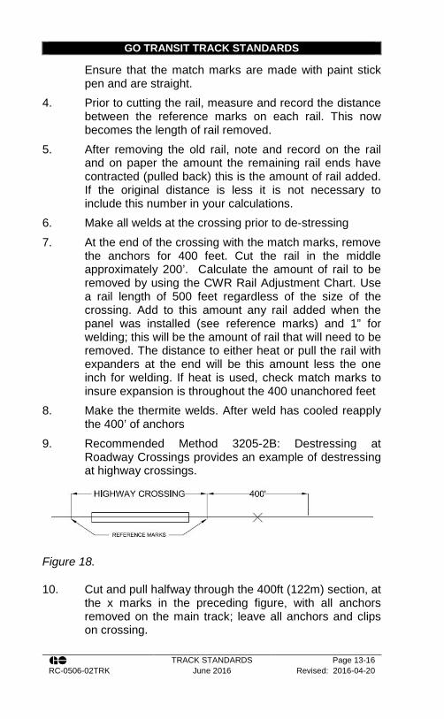
GO TRANSIT TRACK STANDARDS
TRACK STANDARDS Page 13-16 RC-0506-02TRK June 2016 Revised: 2016-04-20
Ensure that the match marks are made with paint stick pen and are straight.
4. Prior to cutting the rail, measure and record the distance between the reference marks on each rail. This now becomes the length of rail removed.
5. After removing the old rail, note and record on the rail and on paper the amount the remaining rail ends have contracted (pulled back) this is the amount of rail added. If the original distance is less it is not necessary to include this number in your calculations.
6. Make all welds at the crossing prior to de-stressing 7. At the end of the crossing with the match marks, remove
the anchors for 400 feet. Cut the rail in the middle approximately 200’. Calculate the amount of rail to be removed by using the CWR Rail Adjustment Chart. Use a rail length of 500 feet regardless of the size of the crossing. Add to this amount any rail added when the panel was installed (see reference marks) and 1” for welding; this will be the amount of rail that will need to be removed. The distance to either heat or pull the rail with expanders at the end will be this amount less the one inch for welding. If heat is used, check match marks to insure expansion is throughout the 400 unanchored feet
8. Make the thermite welds. After weld has cooled reapply the 400’ of anchors
9. Recommended Method 3205-2B: Destressing at Roadway Crossings provides an example of destressing at highway crossings.
Figure 18.
10. Cut and pull halfway through the 400ft (122m) section, at the x marks in the preceding figure, with all anchors removed on the main track; leave all anchors and clips on crossing.

GO TRANSIT RECOMMENDED METHODS
TRACK STANDARDS Page 13-17 RC-0506-02TRK June 2016 Revised: 2016-04-20
Recommended Method 3205-2B: Destressing at Roadway Crossings Example
A crossing is being rehabilitated and new rail panel installed through the crossing. 110 ft. of rail will be replaced. The rail temperature at time of laying the crossing rail was 60°F. The reference marks are now 1/4” further apart. What is the required rail expansion?
Length of rail removed is 110 ft.
Temperature differential = 100 (PRLT) – 60 (present rail temp.) = 40°F
Adjustment required in 400 foot unanchored zone= 1 7/8”
Expansion length required at crossing = 1 7/8” plus 1/4” added rail = 2 1/8”
Cut 3 1/8” at end and pull or heat to a 1” gap for the final.
GO TRANSIT TRACK STANDARDS
TRACK STANDARDS Page 13-18 RC-0506-02TRK June 2016 Revised: 2016-04-20
13.6. Construction/Temporary Crossings
1. All new construction / temporary crossings must be approved by the Rail Corridors Senior Manager of Track and Structures.
2. Crossings shall be constructed per Track Standard Section 13.3 and Appendix U – TEMPORARY Construction Crossings.
3. Filter fabric shall be placed under the crossing surface covering the entire ballast section.
4. Crossing surface shall consist of: a. 7 x 10 inch planks on both sides of each rail with
the ballast or other granular material placed in the centre. This type of crossing is to be used for low traffic temporary crossings only, at the discretion of the Rail Corridors Senior Manager of Track and Structures.
b. 7 x10 inch wide planking laid parallel to the rails over the ties. (7 planks are used per track) Planking is placed between the rails and on the outside of each rail. If a flange-way material is used then the centre plank must be cut to fit.
c. 3 – 12 x ½ inch lag screws and washers shall be used per plank.
d. Flange fillers shall be used on both the gauge and field sides.
5. Crossings shall have: a. A level gradient on either side for a distance of
8m or not less than the maximum length of vehicle using it;
b. Approach grades not greater than 5%; c. A crossing surface of suitable material extending
at least 0.5m beyond the travelled width on both sides measured at right angles to the roadway; and,

GO TRANSIT TRACK STANDARDS
TRACK STANDARDS Page 13-19 RC-0506-02TRK June 2016 Revised: 2016-04-20
d. Be of an overall safe width suitable for the use intended.
6. Crossings shall be cut at the ends as to form a bevel or taper that will act as a deflector.
7. Temporary crossings in concrete tie or steel tie territories shall be lagged into 4x4 lumber slid under the base of the rail, similar to that of a timber tie, at a regular spacing within the ballast profile. a. The crossing timbers must take into account the
use of elastic clips. 8. Heavy use construction crossings shall be replaced
every 3 years or as required. During replacement, the rail, ballast, tie, and fastener condition will be inspected and replacement may be required.
9. Flange-ways shall be kept clear at all times. 10. All new construction and temporary crossings will be
outfitted with manually operated rising barriers. 11. Each barrier shall include padlock fixing points for the
locking arm, particularly in the closed position. 12. All locks to be used shall be approved by the Rail
Corridors Senior Manager of Track and Structures. 13. Barrier shall be type MG19 manufactured by Canadian
Parking Equipment ltd, or an equivalent approved by the Rail Corridors Senior Manager of Track and Structures.
Figure 19. Manually Operated Rising Barrier Type MG19
GO TRANSIT TRACK STANDARDS
TRACK STANDARDS Page 13-20 RC-0506-02TRK June 2016 Revised: 2016-04-20
13.7. Temporary Planking of Tracks
1. Tracks requiring planking for construction purposes shall be constructed as per Track Standard Section 13.7 and Appendix U – TEMPORARY Construction Crossings.
2. Defective ties must be replaced prior to planking. 3. Filter cloth is required between Ties and planking 4. It is the responsibility of the contractor that requested to
planking to ensure that the flange-ways are clear of debris at all times.
5. It is the responsibility of the contractor that requested the planking to ensure that the surface of the planking is kept clear of snow and ice and other debris.
6. Tracks that have been planked must be inspected as per Track Standard Section 14.7
7. Planking MUST be removed at least annually, for a thorough track inspection, and to complete any repairs required unless otherwise directed by the Rail Corridors Manager of Track.
8. It is the responsibility of the contractor that requested the planking to ensure that the planks are removed once the crossing is no longer required.
13.8. Inspection and Testing of Railway Crossing Warning Devices
1. RCWS is defined as Railway Crossing Warning System that consists of: a. Flashing light signals with bell; b. Flashing lights; or c. Automatic bells and gates installed and/or
maintained by the Railway. 2. The normal functioning of any rail crossing warning
system shall not be interfered with in testing or otherwise, without first taking adequate measures to protect the safety of the public or highway traffic which depends upon the normal operation of such systems.

GO TRANSIT TRACK STANDARDS
TRACK STANDARDS Page 13-21 RC-0506-02TRK June 2016 Revised: 2016-04-20
3. Road crossing warning systems consisting of flashing light signals and bells, flashing lights, or automatic bells and gates shall be tested at least once in each calendar week.
4. Where track is used less than once per week, testing of road crossing warning systems shall be as directed by the Rail Corridors Manager of Signals.
5. The person assigned to undertake the test will, when road and railway traffic permits, manually operate the rail crossing warning system for one complete cycle, observing the proper functioning of all visible warning features such as lights, bells, movement of gates, etc. and check for any broken or damaged lenses or other defective parts of the system.
6. If the rail crossing warning system fails to operate or does not operate properly, traffic at the crossing must be protected by flagging immediately. In addition, arrangements must be made by any means available, to advise the Rail Traffic Controller and S&C Maintainer as quickly as possible. If the warning device is for more than four tracks, two flagmen shall be used for flagging protection.
7. Observation of the power “off” or “on” light by the person assigned to make the test is required, and if the light is extinguished or the power is off, the Rail Traffic Controller and S&C Maintainer must be advised promptly and highway traffic protected.
8. The person assigned to undertake the test must complete CNR Form 8328 or the Highway Crossing Warning System performance report (log book), and forward same to the S&C Supervisor at the end of each calendar year, or when the log book is filled. These tests are the responsibility of the Signal Maintainers.

GO TRANSIT RECOMMENDED METHODS
TRACK STANDARDS Page 13-22 RC-0506-02TRK June 2016 Revised: 2016-04-20
Recommended Method 2700-0: Construction and Reconstruction of Grade Crossings in Wood and Concrete Tie Territories
Example: Assume that a crossing on a line carrying 40 MGT annually requires rehabilitation. The road authority advises that the average daily vehicle count for this crossing is 10,000 vehicles per day of which 1,000 are trucks. Find the most appropriate crossing surface for this crossing. First determine the number of car equivalents in thousands per day. There are 1,000 trucks per day and 9,000 cars per day (10,000 - 1,000). To find the daily car equivalents for this crossing take the number of trucks per day and multiply by 100 and add to this number the number of cars per day. 1,000 Trucks x 100 = 100,000 Daily car equivalents = 109,000 Now proceed to the chart and enter from the bottom at 109,000 car equivalents per day and from the right at 40 MGT. The two lines intersect in area 4. Now look under area 4 to determine the crossings best suited for this location. These are as follows:
• full depth (recycled) rubber
• steel reinforced rubber
• concrete panels with rubber flange-ways
• sectional steel panels with rubber flange-ways The crossing surface should then be selected from one of the four surfaces listed above.

GO TRANSIT TRACK STANDARDS
TRACK STANDARDS Page 14-1 RC-0506-02TRK June 2016 Revised: 2016-04-20
Section 14 - Track Inspection
14.1. General Information
1. The Track Supervisor and the Rail Corridors Manager of Track must know that any person designated to do track inspections is qualified and must ensure the quality of inspection.
2. The method chosen for the frequency of track inspections must ensure that the track is safe for operation at the currently authorized speeds. All unsafe conditions found during inspection that cannot be corrected must be properly protected.
3. As a minimum, all tracks must be inspected in accordance with the schedules listed in the current Transport Canada Track Safety Rules.
4. Each inspection must be made on foot or by riding over the track in a vehicle at a speed that allows the person making the inspection to visually inspect the track structure for compliance with Transport Canada and GO Transit requirements. The speed for track vehicles must not exceed the speed prescribed in the GO Transit General Engineering Instructions.
5. Mechanical, electrical, and other inspection devices may be used to supplement visual inspection.
6. When riding over the track in a vehicle, the inspector(s) may inspect up to two tracks at one time provided that: a. Each main track is actually traversed by the
vehicle or inspected on foot on alternate inspections at least once every two weeks, and each siding or crossover is actually traversed by the vehicle or inspected on foot at least once every month.
b. One inspector cannot inspect more than two tracks at one time and cannot inspect any track centred more than 30 feet from the track on which the inspector is riding.
GO TRANSIT TRACK STANDARDS
TRACK STANDARDS Page 14-2 RC-0506-02TRK June 2016 Revised: 2016-04-20
c. track inspection records must indicate all track(s) included in the inspection and indicate which track(s) was traversed by the vehicle or inspected on foot
d. The inspectors view of the track(s) is unobstructed by tunnels, bridges, differences in ground level, or any other circumstances or conditions that would interfere with a clear view of all the tracks they are inspecting
7. When the track is occupied by equipment, the inspection will be made by a walking inspection on each side of the track.
8. For yard tracks, if a track is inspected from an adjacent roadway, the next required track inspection must be completed with the track traversed by the vehicle or inspected on foot.
9. Inactive tracks must be secured in a manner that must prevent use by movements and all assets must be inspected before being used to ensure the track is compliant and safe for all movements at the authorized speed.
10. The Rail Corridors Manager of Track and the Track Evaluation Officer have the authority to order additional inspections if they are required for safe railway operation.
11. Additional track inspections are required under the following conditions: a. strong winds, which may cause trees or other
obstacles to fall on the track; b. heavy rain, snow or repeated freeze-thaw
cycles, which may cause high water, washouts, rock falls, or mud slides;
c. Extreme hot or cold temperatures, which may cause track buckling or rail breaks
d. long dry period combined with track maintenance activities, or during any train operations that may cause fires
e. after an earthquake

GO TRANSIT TRACK STANDARDS
TRACK STANDARDS Page 14-3 RC-0506-02TRK June 2016 Revised: 2016-04-20
f. any other occurrence which may have damaged the track structure
12. For the purposes of forecasting or initiating extreme weather inspections and conversions of rail temperatures in relation to ambient temperatures: a. in hot weather, rail temperature is equal to the
ambient temperature plus 30ºF (16ºC) b. in cold weather, rail temperature is equal to
ambient temperature. 13. The inspections must be carried out by employees who
are qualified under the Transport Canada Track Safety Rules and the GO Transit Track Standards, and under the direction of the Rail Corridors Senior Manager of Track and Structures.
14.2. Frequency of Inspections
1. Minimum track inspection frequencies shall be as outline in the Transport Canada Track Safety Rules, but not less than those stated in Appendix A – Track inspection frequencies in Table 34, Table 35, Table 36, Table 37, and Table 38.
2. An automated geometry inspection is required for all tracks except track of class 1 with annual tonnage of less than 5 MGT and except yard tracks and inactive tracks.
3. A walking inspection must be completed on all tracks per the inspection frequency outlined in Appendix M, but not less than those in the Transport Canada Track Safety Rules.
4. Each turnout, railway crossing at grade, moveable bridge lift rail, derail, sliding joint, or other transition device must be inspected on foot at least monthly.
5. In the case of track that is used less than monthly, each turnout, railway crossing at grade, moveable bridge lift rail, derail, sliding joint, or other transition device must be inspected on foot before it is used.

GO TRANSIT TRACK STANDARDS
TRACK STANDARDS Page 14-4 RC-0506-02TRK June 2016 Revised: 2016-04-20
6. Walking inspections of public crossings shall be undertaken at least annually, with no more than 12 calendar months between inspections.
14.3. Methods of Inspection
1. Inspection methods include walking, or riding over the track in a vehicle in accordance with Track Standard Section 14 -14.4 and with the recommended inspection checklist tabulated in Recommended Method 3100-0: Track Inspection.
2. Hi-rail unit used for inspection must travel at a speed that allows the person making the inspection to visually inspect the track but not exceeding the speeds prescribed in the GO Track General Engineering Instructions.
3. Track shall be inspected by train, at least monthly, riding a forward facing unit when possible. Inspection by train will provide a view of the track and right-of-way and will give an indication of ride quality, but is not included in the count of required inspection by Transport Canada.
4. The Track Supervisor should inspect their area of responsibility at least once every month from the engine of a GO Transit train. For tracks where GO Trains are not permitted (eg. the Pearson Sub), the Track Supervisor should ride in the cab of the UP DMU.
5. Walking inspections on class 3, 4, and 5 main track and sidings, and on class 1 and 2 main tracks that carry more than 25 million gross tons of traffic per year should be carried out in such a manner that priority locations and areas of known problems, such as those outlined in Track Standard Section 14.4, are monitored.
6. Walking inspections on class 1 and 2 main track and sidings that carry less than 25 million gross tons of traffic will be performed as directed by the Rail Corridors Senior Manager of Track and Structures.
7. In addition to the priority locations in Track Standard Section 14.4, Recommended Method 3100-0: Track Inspection provides a checklist that should be followed for walking, routine, and on-train inspections.

GO TRANSIT TRACK STANDARDS
TRACK STANDARDS Page 14-5 RC-0506-02TRK June 2016 Revised: 2016-04-20
14.4. Areas for Inspections
1. Table 23 outlines the Areas for Inspection. Table 23 – Areas for Inspection
Rail a Areas with high numbers of fatigue
related rail defects b Rail defects protected by joint bars c Rail damage which has been
alleviated by grinding d Areas approaching condemning limits
for wear. Where rail wear is at 75% or greater of the condemnable limit, the underside of the rail must be physically inspected.*
e Locations prone to overstressed rail, such as: i. areas where rail repairs have
been made (too little or too much rail installed)
ii. curves iii. areas of severe rail corrugation iv. areas of heavy brake application
(eg. approaches to PSO locations) – moving rail.
v. areas of buffer rails or any joints adjoining CWR
vi. areas of steep grades vii. areas of insufficient or damaged
rail anchors, or significant rail movement
viii. derailment sites or derailment damaged rail
f Signs of rail moving through anchors g Short misalignment, and kinks in
tangent track. Joints a Cracked b Broken c Pumping Bolts a Loose, bent, frozen broken, and
missing track bolts

GO TRANSIT TRACK STANDARDS
TRACK STANDARDS Page 14-6 RC-0506-02TRK June 2016 Revised: 2016-04-20
Plates a Rail base improperly seated in plates Fasteners a High cut spikes and broken screw
spikes Wood Ties a Cluster of defective ties b Gauge problem areas with 1/2 in
(13mm) or greater c Excessive loss of cant d Areas prone to hanging ties, such as
insulated joints, road crossings, and bridge approaches
e Areas of high or broken spikes or timber tie screws
f Areas with high dynamic braking such as controlled locations, PSOs, or stations
g Hanging ties Concrete Ties a Loose or missing clips or insulators b Signs of rail movement c Loose or damaged shoulder castings d Signs of rail seat abrasion e Areas repaired by the use of Laird
Clips f Areas with historical clip failure g Hanging ties Ballast a Sink holes b Mud pumping locations c Frost heave locations d Areas of weak ballast shoulders e Areas where recent program work
has left ballast disturbed f Adequacy of the ballast section at
sags, culverts, ballast deck bridges bridge abutments and locations where vehicles have been driven along the right-of-way or where foot paths may cross tracks
Roadbed / Slope Stability a Areas historically prone to track
geometry problems (surface, line, cross-level)
b Slope stability problems (slip, rock

GO TRANSIT TRACK STANDARDS
TRACK STANDARDS Page 14-7 RC-0506-02TRK June 2016 Revised: 2016-04-20
falls, or mud slides) Drainage a Areas prone to ponding water (beaver
dams, drainage ditches, blocked culverts, etc.)
b Area of high or increased surface run-off (near forestry operations, industry development, high water tables, etc.)
c Areas prone to ice build-up under the plate
d Culverts Transition Areas a Bridge approaches b Concrete tie to wood tie transition
areas Derailment Areas a Substandard conditions or temporary
repairs b Monitor until permanent repairs have
been completed. Direct Fixation Track a Bolts are properly tightened. b Check clips are properly attached and
secured; not rusted c Significant concrete cracking
* Under Head Inspection
b. It is acceptable to conduct under head inspections with an inspection mirror.
c. Look for cracks that cause head-web separation defects. The indications are:
i. In the early stage a wavy, wrinkled line appearing in the fillet under the head.
ii. In mid-stage a small crack will appear along the fillet on either side of the rail head, indicating growth through the web. The crack will progress longitudinally.
iii. In the late stages, rust discoloration bleeding from the crack will be evident. The crack may also extend up into the rail head causing a slight depression in the running surface and sometimes a black line will appear.
d. If any of the above indications are found, the rail shall be replaced immediately.
e. If none of the above indications are found, but rail surface shelling, spalling, and/or corrugation are present, the
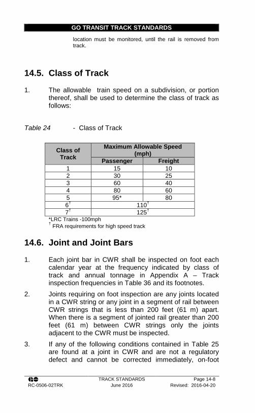
GO TRANSIT TRACK STANDARDS
TRACK STANDARDS Page 14-8 RC-0506-02TRK June 2016 Revised: 2016-04-20
location must be monitored, until the rail is removed from track.
14.5. Class of Track
1. The allowable train speed on a subdivision, or portion thereof, shall be used to determine the class of track as follows:
Table 24 - Class of Track
Class of Track
Maximum Allowable Speed (mph)
Passenger Freight 1 15 10 2 30 25 3 60 40 4 80 60 5 95* 80 6† 110† 7† 125†
*LRC Trains -100mph
† FRA requirements for high speed track
14.6. Joint and Joint Bars
1. Each joint bar in CWR shall be inspected on foot each calendar year at the frequency indicated by class of track and annual tonnage in Appendix A – Track inspection frequencies in Table 36 and its footnotes.
2. Joints requiring on foot inspection are any joints located in a CWR string or any joint in a segment of rail between CWR strings that is less than 200 feet (61 m) apart. When there is a segment of jointed rail greater than 200 feet (61 m) between CWR strings only the joints adjacent to the CWR must be inspected.
3. If any of the following conditions contained in Table 25 are found at a joint in CWR and are not a regulatory defect and cannot be corrected immediately, on-foot
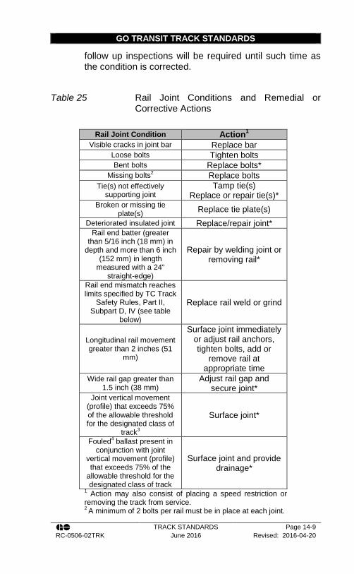
GO TRANSIT TRACK STANDARDS
TRACK STANDARDS Page 14-9 RC-0506-02TRK June 2016 Revised: 2016-04-20
follow up inspections will be required until such time as the condition is corrected.
Table 25 Rail Joint Conditions and Remedial or Corrective Actions
Rail Joint Condition Action1
Visible cracks in joint bar Replace bar Loose bolts Tighten bolts Bent bolts Replace bolts*
Missing bolts2 Replace bolts Tie(s) not effectively
supporting joint Tamp tie(s)
Replace or repair tie(s)* Broken or missing tie
plate(s) Replace tie plate(s) Deteriorated insulated joint Replace/repair joint*
Rail end batter (greater than 5/16 inch (18 mm) in
depth and more than 6 inch (152 mm) in length
measured with a 24” straight-edge)
Repair by welding joint or removing rail*
Rail end mismatch reaches limits specified by TC Track
Safety Rules, Part II, Subpart D, IV (see table
below)
Replace rail weld or grind
Longitudinal rail movement greater than 2 inches (51
mm)
Surface joint immediately or adjust rail anchors, tighten bolts, add or
remove rail at appropriate time
Wide rail gap greater than 1.5 inch (38 mm)
Adjust rail gap and secure joint*
Joint vertical movement (profile) that exceeds 75% of the allowable threshold for the designated class of
track3
Surface joint*
Fouled4 ballast present in conjunction with joint
vertical movement (profile) that exceeds 75% of the
allowable threshold for the designated class of track
Surface joint and provide drainage*
1 Action may also consist of placing a speed restriction or removing the track from service. 2 A minimum of 2 bolts per rail must be in place at each joint.

GO TRANSIT TRACK STANDARDS
TRACK STANDARDS Page 14-10 RC-0506-02TRK June 2016 Revised: 2016-04-20
3 Joint lateral and vertical movement is the apparent visible movement measured at the joint. 4 Fouled ballast is defined as ballast that is so contaminated with fines that it contains standing water within the track structure at joints * Or conduct follow-up inspections every other week until the defects are repaired or removed
4. Jointed and CWR main line track requires on foot inspection of all rail joints in bridges be undertaken at the following frequencies: a. Track with less than 10 MGT annually - once per
year. b. Track with 10 MGT or great annually - twice per
year. 5. When performing inspections, be aware of line or
surface deviations possibly due to insufficient ballast 6. Insufficient ballast is defined as:
a. Either end of the tie fully exposed or 50% empty cribs of 6 or more consecutive ties coupled with track surface; or,
b. Alignment deviations that exceed 75% of allowable threshold for designated class of track.
c. This requirement applies when the ambient temperature exceeds 85º F (29 ºC) or is expected to exceed 85º F (29 ºC) within the next 24 hours. When this combination exists, reduce the speed to the next lower class of track and continue to monitor until repaired. Speed restriction may be removed and monitoring will not be necessary when the ambient temperature drops below 85ºF (29ºC).
14.7. Railway Crossings at Grade
1. Inspections of all railway crossings at grade (diamonds) shall be conducted as follows: a. Every time the crossing is traveled over by hi-rail
it shall be visually inspected for defects.

GO TRANSIT TRACK STANDARDS
TRACK STANDARDS Page 14-11 RC-0506-02TRK June 2016 Revised: 2016-04-20
b. Crossings shall be inspected at least monthly on foot measuring gauge and looking closely at the condition of all components.
c. See inspection checklist references in Track Standard Section 17 -
2. Unsafe conditions on either railway which cannot be corrected immediately will be reported to the Rail Traffic Controller or Train Dispatcher and proper action taken to protect traffic on all routes.
14.8. Direct Fixation Track
1. Direct Fixation Track (DFT) is an “open” track-form with nearly all of the major components easily visible and accessible for inspection and maintenance. As compared to traditional ballasted track, DFT is fixed directly to a concrete slab or plinth which eliminates the requirement for ballast and ties.
2. All bolts must be checked that they are tight, as bolts are subject to loosening. a. Note that bolts on new construction are
particularly prone to loosening, until such time as mating parts wear in and seat to each other.
b. Bolts are located at rail fastener locations (plates), guard rails, and numerous nuts and bolts in special track work.
3. Elastic rail clips must be regularly checked. 4. Heavily corroded clips must be replaced to avoid the
clips from “rusting together” with the rail fasteners (plates).
5. Missing clips must be replaced immediately. 6. Clips subject to constant damp conditions (e.g. in
tunnels) or to heavy salting (e.g. through station platforms, rail crossings), must be galvanised.
7. DFT track must be kept clean at all times, in particular in locations of heavy salting.
8. Each Spring DFT track covered track areas near heavy salting locations must be washed off with water to
GO TRANSIT TRACK STANDARDS
TRACK STANDARDS Page 14-12 RC-0506-02TRK June 2016 Revised: 2016-04-20
remove any excess salt. This can be done with a firehose and water or other approved method.
9. In heavy sanding locations, the DFT track bed must be clean at least annually. (e.g. with a vacuum)
10. When rail begins to wear in the curves, the gauge of the track needs to be adjusted to meet the requirements of the class of track as per Appendix B – Priority Defects and Appendix C – Urgent Defects. Use the provided DFT Fastening Plates to adjust gauge as required.
11. Cracks in concrete are a normal occurrence. Any cracks greater than 1/64 in. (0.4 mm) must be reported to the Rail Corridors Manager of Bridges and Structures.
12. All rail breaks in DFT must be documented and forwarded immediately to the Rail Corridors Manager of Track.
13. When a DFT fastener plate is required to be replaced, prior to a new plate being installed, the concrete base must be inspected to determine the cause of the fastener failure. a. Any voids found under the fastener plate must
be repaired before installing the new fastener plate.
b. If the anchor for the bolts sits above the plane of the concrete, the anchor insert must be ground flush to the concrete surface and then epoxy paint applied to the bare steel.
14. If the anchor insert is found to be defective, it must be replaced. a. This is done by core drilling and grouting a new
insert in its place. b. The new insert must be perpendicular to the
bottom plate of the fastener, flush or slightly below the surface of the concrete, and not in contact with the sides of the cored hole.
c. Any grout to be used must be approved by the Rail Corridors Manager of Bridges and Structures. It is recommended to use a two component Epoxy grout.
GO TRANSIT TRACK STANDARDS
TRACK STANDARDS Page 14-13 RC-0506-02TRK June 2016 Revised: 2016-04-20
d. A template must be used as a guide for positioning the new insert.
14.9. Culverts and Drainage
1. General inspections of all culverts and surface drainage conditions will be conducted by track Inspectors in conjunction with track inspections.
2. Culvert inspections are for the purpose of ensuring: a. Hydraulic flow can be observed without
obstruction upstream and downstream of the inlet and outlet;
b. Site conditions have not changed in a manner that impacts drainage through assessment of land use and ditch conditions;
c. The structural integrity of the culvert is sufficient to support track, ballast, and embankment material, and no voids are observed in the ballast or embankment; and
d. Identification of maintenance that may be required prior to the next inspection.
3. Culverts with a diameter of 36 inches (915 mm) or less must be inspected either by foot or from hi rail vehicle annually with no more than 540 days between inspections.
4. In the cases where defects are observed, the Manager of Bridges and Structures must be notified promptly, to determine remedial action required.
5. Beaver dams located upstream from the track in streams that flow under or near the track represent a potential hazard. The Track Supervisor must arrange for regular inspections of beaver dams on their territory and take the necessary protective action if conditions are hazardous. On certain territories, an aerial inspection of dams may also be required in the spring and fall of each year to support ground inspections.
6. An up-to-date list of beaver dams will be maintained on each Track Supervisors territory. The list should include:

GO TRANSIT TRACK STANDARDS
TRACK STANDARDS Page 14-14 RC-0506-02TRK June 2016 Revised: 2016-04-20
a. The subdivision mileage; b. The side of the track on which the dams are
located; c. The number of dams; d. Whether the dams are upstream or downstream; e. The distance from each dam from the track; f. Remarks regarding the dams; g. Water fluctuation; and h. The date of the inspection.
14.10. High Water and Spring Run-Off Inspections
1. Joint inspections between the Rail Corridors Bridges and Structures group and the Track Supervisor must be completed every Spring, and as required.
2. With the onset of Spring flooding conditions, snowmelt runoff, ice movements and precipitation, the following steps need to be taken to prevent bridge and culvert washouts: a. All railroad employees should be on the lookout
for water related problems as a component of their regular duties. Concerns should be reported to the Manager of Bridges and Structures
b. All employees must report: i. Inlet conditions:
• Watercourses with lower or higher than normal spring flow discharges. If creek discharges are less than usual or if debris and mud are evident in the flow, an upstream watercourse blockage may exist
• Flow constraints, such as debris building up at the culvert inlet
GO TRANSIT TRACK STANDARDS
TRACK STANDARDS Page 14-15 RC-0506-02TRK June 2016 Revised: 2016-04-20
should be removed to restore normal flow through the culvert
• Water ponding at the inlet to a culvert
• Water levels higher on one side of the track than the other side.
c. Track inspectors must inspect bridges for track alignment and level during the Spring runoff
d. Typical problems experienced by bridges in spring conditions of snowmelt and ice movement are: i. Scour conditions at substructures (piers
and abutments). Eddying or dirty water around the substructure base may be a sign of scouring
ii. Failure of supports (particularly for trestle type bridges) due to ice loads or debris
iii. Loss of substructure support causing subsidence or sway of bridges
iv. Inadequate bank protection during Spring Runoff conditions
v. Failure or poor condition of ice protection measures such as noses on piers or upstream protection structures.
14.11. Gas Welded Rail Inspection Policy
1. This policy shall be in effect from October 1 to March 1 and other times when the ambient temperature is expected to fall below 25°F (-4°C).
2. For main track on the core route that contains gas welded continuous welded rail, the minimum inspection frequency is amended as follows: a. Three times weekly with at least 1 calendar day
between inspections.

GO TRANSIT TRACK STANDARDS
TRACK STANDARDS Page 14-16 RC-0506-02TRK June 2016 Revised: 2016-04-20
b. The Track Supervisor must make every effort to personally perform at least one inspection per week.
c. Additional inspections on secondary main tracks and other tracks shall be as directed by the Rail Corridors Senior Manager of Track and Structures.
14.12. Record of Track Inspections
1. All persons engaged in making inspections will prepare and sign a record of each inspection on the day the inspection is made in accordance with Transport Canada rules. The report shall be retained for at least one year after the date of the inspection. After this time period, all documentation shall be submitted to RC through GO Transit’s document management system.
2. Records must include the following: a. The track inspected, including the from and to
mileages of the main track and siding inspected b. The date of the inspection c. Name and employee ID of the qualified
inspector d. Signature of the qualified inspector e. The method of inspection and whether the track
was observed or traversed f. The type of inspection (e.g. regulatory, special,
joint bar inspection, etc.) g. The location and nature of any rail or track
defects found including any differences from the requirements of the Transport Canada Track Safety Rules.
h. The remedial action taken and the date of the action.
3. The following inspection forms should be used for inspections: a. Track inspection form for regulatory defects

GO TRANSIT TRACK STANDARDS
TRACK STANDARDS Page 14-17 RC-0506-02TRK June 2016 Revised: 2016-04-20
b. Track inspection form for non-regulatory defects c. Monthly Yard and Other Track inspection form d. Monthly Turnout inspection form e. Detailed Turnout Inspection Form f. Track Crossing Inspection report g. Annual Derail inspection form h. Joint Bar inspection form (jointed track) i. Joint bar inspection form (CWR track)
14.13. Extreme Cold Weather Inspections
1. Daily cold weather track inspections will be under taken on core lines under the following conditions:
Track Conditions
Either Condition Met Extreme Cold Temperature
Rapid Drop in Temperature
Susceptible to Cold
< -13ºF (< -25ºC) >45ºF
(>25ºC) in 24 hours All Tracks < -22 ºF
(< -30ºC)
2. Lines shall be considered susceptible to cold weather related rail failure if any one of the following conditions applies: a. Non-signalled territory. b. Jointed and/or gas welded rail. c. Rail of 115 RE weight or lighter subject to rail
car gross weight of 286,000 lbs. d. Rail with a history of frequent defects as
calculated using the 3-year RDI. 3. Additional track inspections should also be considered
during the first “cold snap” of the season. 4. During winter, at times of snow accumulations, watch for
signs of screw spike / cut spike failure on curves equipped with rolled plates and 16 inch modified eccentric plates with welded e-clip shoulders. Disturbance of the snow may be evidence of lateral

GO TRANSIT TRACK STANDARDS
TRACK STANDARDS Page 14-18 RC-0506-02TRK June 2016 Revised: 2016-04-20
movement of the tie plates due to weaken fasteners and may be accompanied by lifting/canting of the plate.
14.14. Cold Weather Speed Restrictions
1. In areas identified as having rail with a history of frequent defects the following cold weather temporary speed restrictions will be put in place: a. When temperature is below -13ºF (-25ºC), all
passenger trains shall be restricted to a speed of 60mph or track speed, whichever is more restrictive.
b. When temperature is below -13ºF (-25ºC), all freight trains shall be restricted to a speed of 40mph or track speed, whichever is more restrictive.
2. Track protected by a ‘cold weather slow order’ must be inspected daily.
14.15. Icing Conditions Under Rail
1. During the winter months under snow conditions, inspectors must look for icing between the tie plates and the base of the rail. Progressive ice build-up may cause the rail base to clear the shoulders of the tie plate resulting in wide gauge under loaded conditions. The condition can be discovered to some extent by looking for a disturbance in the snow along the field side of the high or low rail of a curve. A fresh snowfall may hide this disturbance, making additional checks essential.
2. In locations where ice build-up is likely to occur, snow must be removed and tie plates examined for ice build-up.
3. Icing is most likely to occur where one or more of the following conditions exist: a. Hanging ties; b. Centre bound track; c. High spikes; d. Corrugated rail;

GO TRANSIT TRACK STANDARDS
TRACK STANDARDS Page 14-19 RC-0506-02TRK June 2016 Revised: 2016-04-20
e. High ballast or build-up of engine sand in the tie cribs directly under the rail;
f. Where CWR was laid above the desired rail laying temperature, which causes CWR strings to cant inward creating space for ice formation between the base of the rail and the top of the tie plate; and/or
g. Where poor drainage conditions are known to cause ice build-up.
14.16. Extreme Hot Weather Inspections
1. Whenever ambient (air) temperature exceeds 86ºF (30ºC) or during periods of significant seasonal increase in temperature (i.e. Spring), hot weather track patrols must be undertaken between the hours of 11:00 and 22:00.
2. Hot weather patrols may be suspended if temperatures have stabilized and previous inspections have shown that the track structure is stable and complies with standards.
14.17. Hot Weather Speed Restrictions
1. Hot weather TSOs must be applied on portions of Subdivisions where the temperature threshold exceeds 90ºF (32ºC) or any one of the following track conditions are known to exist: a. Lateral or vertical movement of rail (e.g. “wavy”
or improperly seated rail); b. Kinky rail that is riding up or out of the tie plates
or is crowding the shoulder of the tie plates on curves;
c. Deviations in alignment; d. Movement of ties (e.g. gaps or voids in ballast at
tie ends or in cribs); e. Rail base not properly seated in the plates; f. Insufficient ballast section (e.g. weak shoulders,
empty cribs) especially at approaches to

GO TRANSIT TRACK STANDARDS
TRACK STANDARDS Page 14-20 RC-0506-02TRK June 2016 Revised: 2016-04-20
bridges, road crossings turnouts, interlockings, sliding joints, and other fixed locations;
g. Rail running through anchors or spikes; h. Churning of ballast caused by tie movement
resulting in gauge and line kinks; i. “Tight steel“ (e.g. areas of frequent dynamic
brake application, approaches to PSO’s, bottoms of grades, etc.);
j. Areas where joints adjoin CWR. Bolts must be inspected for straightness when rail gaps are closed;
k. Recently completed track work; l. Cluster of high spikes and poor ties; m. Hanging ties on bridge approaches; n. Longitudinal movement of a switch point in
relation to stock rail, resulting in improper switch adjustment;
o. New installations of culverts , turnouts, and road crossings;
p. Rail gaps that are not closed when the rail temperature is 22ºC ( 40ºF) above the PRLT must be reported to the Rail Corridors Manager of Track and the Track Supervisor;
q. Spike lining is not permitted in CWR territory except when it is not possible to line the track;
r. Shimming areas must be inspected closely for high spikes and spike killed ties. Anchors must be removed from shimmed track;
s. Particular attention must be paid to curves in CWR territory. When 11” and single shoulder tie plates are used, watch for rail canting to the outside of the curve. The high rail will lift off the tie plate on the gauge side, the low rail on the field side;
t. Particular attention should be paid to welds in curves. Poor alignment of welds will result in heavy, unusual rail wear. Additional excessive

GO TRANSIT TRACK STANDARDS
TRACK STANDARDS Page 14-21 RC-0506-02TRK June 2016 Revised: 2016-04-20
forces will be placed on the high rail, causing inside spikes to lift, and track to go out of line;
u. Particular attention should be paid to compromise rail joints and to locations where rail repairs were performed during winter to replace service failed or defecting rails;
v. In areas of severe corrugation in curves, attention should be paid to rail creep;
w. Grade instability; or x. Any other areas having a history of lateral
instability, site of derailment, washout, etc., or where Track Supervisors have a concern.
2. When the temperature exceeds the threshold level, a speed restriction of one class of track or 60 MPH (Passenger) 40 MPH (Freight) whichever is greater must be placed.
3. When deterioration of these conditions are present as listed in this section, a speed restriction of 30MPH (Passenger) 25 MPH (Freight) or less must be placed or track removed from service until repair or adjustment is made.
4. When there are indications that a track buckle may be about to occur, immediately take the following steps to protect train traffic until the condition is corrected: a. Place a 10mph slow order; or b. Stop traffic, if the situation warrants.
5. This policy does not supersede timetable instructions governing either the operation of unit trains over specified branch lines or the movement of trains on subdivisions equipped with Hot Box Detector talkers broadcasting the ambient temperature.

GO TRANSIT RECOMMENDED METHODS
TRACK STANDARDS Page 14-22 RC-0506-02TRK June 2016 Revised: 2016-04-20
Recommended Method 3100-0: Track Inspection Recommended Checklist
ITEM TO CHECK
WHAT TO LOOK FOR
HI-RAIL WALKING TRAIN
Rail
Broken, vertical split heads, crushed heads, engine burns, discoloration, wear.
Broken, vertical or horizontal split heads, rail head surface collapse, crushed heads, corrugation, wear, spalls, shelling, engine burns, rail end batter, discoloration, rust streaks, rail wear, underside of rail head, damage by equipment.
Broken, rough
Bars Broken Broken, bent, cracked -
Bolts Loose, missing Loose, missing, bent - Washers - Missing -
Plates Broken, missing Broken, bent, badly corroded, missing, skewed
-
Spikes High, missing High, missing, bent -
Anchors Off, damaged, insufficient
Off, loose, away from tie or plate, damaged, insufficient
-
Ties Broken, damaged by equipment
Broken, split, spike killed, plate cut, damaged by equipment
-
Concrete Ties broken, damaged by equipment
Broken, cracked, centre-bound, loose or damaged shoulders, skewed, abraded rail seat, worn shoulders, damaged by equipment
-
Clips Missing, damaged Missing, damaged, loose -
Insulators Missing Missing, worn, damaged, out of position
-
Pads - Missing, worn, out of position -
Ballast Section Ballast low in cribs or shoulder
Cribs not full, low shoulder, narrow shoulder.
-
Ballast Pumping, fouled Pumping, fouled, hanging ties
-
Line Misalignment Misalignment Misalignment, ride quality
Icing Conditions
Ice build-up between base of rail and tie plate, raised spikes, churned ice
Ice build-up between base of rail and tie plate, raised spikes, churned ice chunks , wide gauge
Churned Ice, rough ride-
Surface Poor surface Poor surface Poor surface, ride quality Cross Level Poor cross level Poor cross level Ride quality

GO TRANSIT RECOMMENDED METHODS
TRACK STANDARDS Page 14-23 RC-0506-02TRK June 2016 Revised: 2016-04-20
Gauge
Wide / Irregularities, wheel flange marks, raised or tipped spikes, plate cutting or movement Irregularities
Wide / Irregularities, wheel flange marks, raised or tipped spikes, plate cutting or movement
Irregularities, ride quality
Turnouts Misalignment, components damaged, loose, missing, worn
As per Track Standard Section 16 -
Ride quality
Railway Crossings (Diamonds)
Misalignment, components damaged, loose, missing, worn
As per Track Standard Section 17 -
Ride quality
Vegetation
Contacting equipment, restricting visibility, fire hazard, Restricting drainage, contacting wires, fouling ballast,
Contacting equipment, restricting visibility, fire hazard, Restricting drainage, contacting wires, fouling ballast,
Contacting equipment, restricting visibility, fire hazard, Restricting drainage, contacting wires, fouling ballast
Drainage
Ditches or culverts blocked, beaver activity, high water
Ditches or culverts blocked, beaver activity, high water
High water
Slides Slides, rock falls Slides, rock falls Slides, rock falls
Fencing Damaged, open gates, livestock on R.O.W.
Damaged, open gates, livestock on R.O.W.
Damaged, open gates, livestock on R.O.W.
Clearances Restricted clearances Vertical & horizontal restricted clearances
-
Highway and Farm Crossings
Missing or high planks or other surface material, high spikes, obstructed flange-ways, restricted sight lines Warning devices - damaged or missing gates, lenses, bulbs, signs, masts, 1-800 number label
Loose, missing or high planks or other surface material, high spikes, obstructed flange-ways, restricted sight lines Warning devices - damaged or missing gates, lenses, bulbs, signs, masts, 1-800 number label, power “off” or “on” lights
Ride quality, restricted visibility Warning devices - damaged or missing gates, inoperable
Track Signs Defective, missing, obstructed
Defective, missing, obstructed,
Defective, missing, obstructed

GO TRANSIT TRACK STANDARDS
TRACK STANDARDS Page 15-1 RC-0506-02TRK June 2016 Revised: 2016-04-20
Section 15 - Track Geometry
15.1. Track Geometry Maintenance Standards
1. All tracks must meet or exceed the track geometry standards defined in the GO Transit Track Standards and the Transport Canada Track Safety Rules.
2. Track geometry standards are defined for five classes of track based on maximum operating speeds for passenger and freight trains.
3. Track Geometry can be measured by IRIS, the Andian car, Light Geometry Inspection Vehicle (LGIV), Heavy Geometry Inspection Vehicle (HGIV), or by hand measurements.
4. Deviations exceeding Transport Canada Track Safety Rules minimum safety requirements for track geometry are defined as “URGENT” defects.
5. Deviations approaching Transport Canada Track Safety Rules minimum safety requirements for track geometry are defined as “NEAR URGENT” conditions.
6. Deviations exceeding GO Transit recommended maintenance tolerances are defined as “PRIORITY” conditions.
7. Where a portion of track exceeds the limits defined as “PRIORITY”, the condition must be monitored until it is repaired to ensure it does not escalate to an “URGENT” defect.
8. The following approach is to be used in responding to PRIORITY defects and combinations of PRIORITY defects: a. Address combination defects (e.g. defects within
100 ft. (30.5m) of each other) in the following order: i. Combination defects on curve spirals. ii. Combination defects on curve body.

GO TRANSIT TRACK STANDARDS
TRACK STANDARDS Page 15-2 RC-0506-02TRK June 2016 Revised: 2016-04-20
iii. Combination defects near changes in track modulus (e.g. near bridges, crossings, turnouts, etc.).
b. address all other PRIORITY defects 9. When unloaded track is measured to determine
compliance with this Track Standard the amount of rail movement, if any, which occurs when the track is loaded must be added to the measurement of the unloaded track.
10. Where speed related track geometry defects are detected during track geometry (I.R.I.S.) truck inspections, Appendix D – Allowable TSO for IRIS Truck Defects – Passenger and Appendix E – Allowable TSO for IRIS Truck Defects – Freight may be used to determine the maximum Temporary Slow Order speed to be applied for the seventy-two (72) hour period immediately following the inspection.
11. If the track defect has not been repaired upon the expiration of the seventy-two (72) hour period, the temporary slow order speed must be revised, restricting trains to a maximum speed that is within the track class allowed by the severity of the defect(s). (See Appendix B – Priority Defects and Appendix C – Urgent Defects).
12. Details of remedial action or temporary slow orders applied MUST be recorded on the exception reports initialled and dated for all URGENT, NEAR URGENT, and PRIORITY defects.
15.2. Track Geometry Conditions
1. Gauge a. Standard gauge is 56½ in. (1435 mm) on
tangents and curves up to 14°. Refer to Track Standard Section 3.2 for standard gauge of curves over 14°.
b. The gauge at hotbox detectors and for a minimum of 50 ft. (15m) in either direction must be maintained between 56½ in (1435mm) and 56¾ in (1441mm).

GO TRANSIT TRACK STANDARDS
TRACK STANDARDS Page 15-3 RC-0506-02TRK June 2016 Revised: 2016-04-20
c. Gauge shall not be allowed to become greater than 57¾ in. (1,466 mm). If loaded or unloaded gauge has been found to exceed this limit, the track shall be removed from service immediately.
d. Gauge should not be allowed to become tighter (less) than 56 in. (1,422mm)
e. Where gauge is found to be less than 56 in. (1,422mm) must be reduced to the lesser of: i. The maximum permissible speed for the
next lower class of track, or ii. The maximum permissible speed for the
class of track as determined from Table 26:
Table 26 Narrow Gauge TSO Requirements
Change in Gauge over 20ft (6m) on either side of the
narrow point.
Reduce Speed to Class of Track
> 7/8” (22mm) and ≤1-1/8” (29mm) 3
>1-1/8” (29mm) and ≤1½” (38mm) 2
>1½” (38mm) 1
2. Alignment a. The measurement for alignment shall be the
maximum mid-ordinate (positive or negative) in inches, of a 62 ft. (18.9m) or 31 ft. (9.5m) chord measured at the gauge point.
b. On curved track, the high (outside) rail shall be used as the line rail. On tangent track, either rail may be used as the line rail but the same rail must be used throughout the tangent.
c. The maximum mid-ordinate shall be established by centring visible misalignments on the chord.
d. If 62 ft. (18.9m) chords are used, the mid-ordinate (in inches) is in a 1 to 1 relation with the

GO TRANSIT TRACK STANDARDS
TRACK STANDARDS Page 15-4 RC-0506-02TRK June 2016 Revised: 2016-04-20
degree of curve. If 31-foot (9.5m) chords are used, the mid-ordinate (in inches) must be multiplied by 4 to obtain the degree of curve.
Figure 20. Alignment
e. The degree of curve is determined by averaging the degree of curvature of 11 points (the point of concern plus 5 points on either side) over a 155 ft. (47.2m) track segment at 15.5 ft. (4.72m) spacing. If the curve is less than 155 feet (47.2m), then the average is taken throughout the full length of the body of the curve.
3. Superelevation a. Except as provided in Section 12 for limits of
Cross level from Design, the outside rail of a curve shall not be lower than the inside rail nor have more than 6” (152mm) of superelevation. Design superelevation should not exceed 5” (127mm).
b. When superelevation on a curve is less than the amount required, the curve must be checked for V-max.
c. The designated elevation at any point on a curve is determined by averaging the elevation over the same track segment as used in Track Standard Section 15.2.2.e above.
d. Where superelevation is runout onto tangent track per the conditions in Track Standard Section 19.3 and Recommended Method 1305-0: Determining Superelevation, Spiral Length and Maximum Train Speed on Curves, designated elevation in the spiral and tangent

GO TRANSIT TRACK STANDARDS
TRACK STANDARDS Page 15-5 RC-0506-02TRK June 2016 Revised: 2016-04-20
shall be based on the maximum allowable runout permitted.
4. Surface a. The maximum allowable deviations for surface
related defects are listed in Appendix C – Urgent Defects.
b. The measurement for SURFACE shall be the maximum positive or negative mid-ordinate, in inches, of a 62 ft. (18.9m) chord measured along the top surface of the rail.
c. The maximum mid-ordinate shall be established by centring visible peaks or sags on the chord.
5. Cross Level a. The measurement for cross-level shall be the
difference in elevation, in inches or mm, between the grade rail and the other rail, measured with a level board or approved track gauge.
b. Designated elevation at any point on a curve is determined by averaging the elevation of 11 points (the point of concern plus 5-points on either side) over a 155 ft. (47.2m) track segment at 15.5 ft. (4.72m) spacing. If the curve is less than 155 feet (47.2m), then the average is taken through the full length of the body of the curve. The degree of curve is determined by averaging the degree of curvature over the same track segment as the elevation.
c. On curved track, the grade rail is the low (inside) rail. On tangent track, either rail may be used as the grade rail, but the same rail must be used throughout the tangent.
d. The difference in cross-level readings shall be used to calculate WARP 31 and WARP 62. Measurement for cross level shall be taken so as to ensure that the maximum deviations are recorded. Both of these terms describe variations in cross level which contribute to the
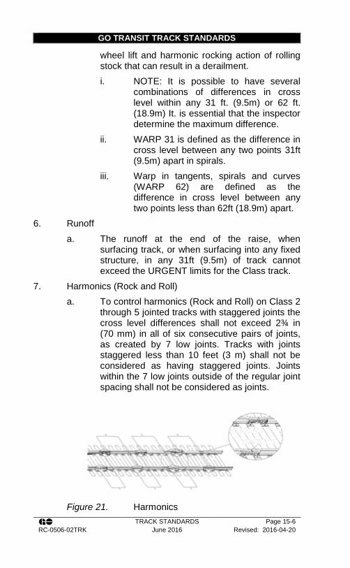
GO TRANSIT TRACK STANDARDS
TRACK STANDARDS Page 15-6 RC-0506-02TRK June 2016 Revised: 2016-04-20
wheel lift and harmonic rocking action of rolling stock that can result in a derailment. i. NOTE: It is possible to have several
combinations of differences in cross level within any 31 ft. (9.5m) or 62 ft. (18.9m) It. is essential that the inspector determine the maximum difference.
ii. WARP 31 is defined as the difference in cross level between any two points 31ft (9.5m) apart in spirals.
iii. Warp in tangents, spirals and curves (WARP 62) are defined as the difference in cross level between any two points less than 62ft (18.9m) apart.
6. Runoff a. The runoff at the end of the raise, when
surfacing track, or when surfacing into any fixed structure, in any 31ft (9.5m) of track cannot exceed the URGENT limits for the Class track.
7. Harmonics (Rock and Roll) a. To control harmonics (Rock and Roll) on Class 2
through 5 jointed tracks with staggered joints the cross level differences shall not exceed 2¾ in (70 mm) in all of six consecutive pairs of joints, as created by 7 low joints. Tracks with joints staggered less than 10 feet (3 m) shall not be considered as having staggered joints. Joints within the 7 low joints outside of the regular joint spacing shall not be considered as joints.
Figure 21. Harmonics
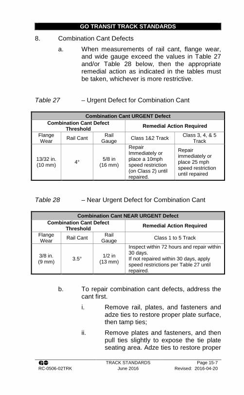
GO TRANSIT TRACK STANDARDS
TRACK STANDARDS Page 15-7 RC-0506-02TRK June 2016 Revised: 2016-04-20
8. Combination Cant Defects a. When measurements of rail cant, flange wear,
and wide gauge exceed the values in Table 27 and/or Table 28 below, then the appropriate remedial action as indicated in the tables must be taken, whichever is more restrictive.
Table 27 – Urgent Defect for Combination Cant
Combination Cant URGENT Defect Combination Cant Defect
Threshold Remedial Action Required
Flange Wear Rail Cant Rail
Gauge Class 1&2 Track Class 3, 4, & 5 Track
13/32 in. (10 mm) 4° 5/8 in
(16 mm)
Repair Immediately or place a 10mph speed restriction (on Class 2) until repaired.
Repair immediately or place 25 mph speed restriction until repaired
Table 28 – Near Urgent Defect for Combination Cant
Combination Cant NEAR URGENT Defect Combination Cant Defect
Threshold Remedial Action Required
Flange Wear Rail Cant Rail
Gauge Class 1 to 5 Track
3/8 in. (9 mm) 3.5° 1/2 in
(13 mm)
Inspect within 72 hours and repair within 30 days. If not repaired within 30 days, apply speed restrictions per Table 27 until repaired.
b. To repair combination cant defects, address the
cant first. i. Remove rail, plates, and fasteners and
adze ties to restore proper plate surface, then tamp ties;
ii. Remove plates and fasteners, and then pull ties slightly to expose the tie plate seating area. Adze ties to restore proper

GO TRANSIT TRACK STANDARDS
TRACK STANDARDS Page 15-8 RC-0506-02TRK June 2016 Revised: 2016-04-20
tie plate seating surface and reinstall tie and fasteners and then tamp the ties; or
iii. Replace existing ties.
15.3. Application of Slow Orders for Defective Track
1. Where a portion of track exceeds the limits defined as “URGENT”, one of the following actions must be immediately taken before the operation of the next train over the defect(s): a. the defect(s) must be repaired to within the
allowable tolerance; b. except as prescribed in Track Standard Section
15.1 for PRIORITY defects, if the defect is a speed-related type, a temporary slow order (TSO) must be placed restricting trains to a maximum speed which is within the track class allowed for the severity of the defect(s), (refer to Appendix C – Urgent Defects); or
c. operation over the track must be halted d. Track must be removed from service if defects
exceed Class 1 limits
15.4. Responsibility
1. The Track Supervisor is responsible for: a. Checking the deterioration in track geometry
between IRIS tests; b. Ensuring that track geometry is maintained with
the track geometry standards, or providing appropriate track protection; and,
c. Accompanying the IRIS testing vehicle when it is testing primary and secondary main lines in their respective territory.
GO TRANSIT TRACK STANDARDS
TRACK STANDARDS Page 15-9 RC-0506-02TRK June 2016 Revised: 2016-04-20
2. All tracks MUST meet or exceed the track geometry standards defined in the GO Transit Track Standards and the Transport Canada Track Safety Rules.

GO TRANSIT TRACK STANDARDS
TRACK STANDARDS Page 16-1 RC-0506-02TRK June 2016 Revised: 2016-04-20
Section 16 - Turnout Inspection
16.1. General Information
1. All unsafe conditions found during the inspection must be corrected immediately or properly protected.
2. The inspections must be carried out by employees who are qualified in accordance with Transport Canada Track Safety Rules, and GO Transit Track Standards, and must be under the direction of the Rail Corridors Senior Manager of Track and Structures.
3. In addition to the inspections, each main track switch Class 3 through 5 tracks shall be operated in all its positions during one inspection in every 3 month period.
16.2. Types of Inspections
1. There are three types of turnout inspections: a. Routine Inspection b. Walking Inspection c. Detailed Inspection
16.3. Frequency of Inspections
1. The frequency of turnout inspects must ensure that the track is safe for operation at currently authorized speeds.
2. Turnouts must be inspected at the minimum frequencies specified by the Transport Canada Track Safety Rules or the GO Transit Track Standards, whichever is more restrictive. These frequencies can be found in Appendix A – Track inspection frequencies in Table 38.
3. The Rail Corridors Manager of Track and the Track Evaluation Officer have the authority to order additional inspections at their discretion.
GO TRANSIT TRACK STANDARDS
TRACK STANDARDS Page 16-2 RC-0506-02TRK June 2016 Revised: 2016-04-20
16.4. Record of Turnout Inspection
1. A report of each Walking Inspection and Detailed Inspection must be prepared on a prescribed turnout inspection form on the same day that the inspection is performed. The inspection report must be signed by the person making the inspection, and retained at the designated location for at least one year.
16.5. Walking Turnout Inspection
1. Walking turnout inspections must include the following procedures: a. Check the throw and adjustment for any lost
motion (check that the eyebolt is adjusted to compensate for any lost motion). On power operated switches, arrange with the RTC to have the switch taken off power. Observe if the points are closing properly. Advise the Signal Maintainer accordingly.
b. Check the condition of the eyebolts, its position in the mast barrel, and the condition of the connecting rod, and all switch rods, including for wear.
c. Check the switch points for wear, for fit against, and for proper height above the stock rail. Gaps in switch points, regardless of size, are unacceptable. The points must fit tightly against the stock rail.
d. Check the switch points are properly adjusted and secured.
e. Check to see that the switch points are not skewed. They must be installed directly opposite each other. If skewing should develop, adequate rail anchors must be installed to resist rail movement.
f. Check the riser slide plates and rail braces. g. Check that all cotter pins are in place.
GO TRANSIT TRACK STANDARDS
TRACK STANDARDS Page 16-3 RC-0506-02TRK June 2016 Revised: 2016-04-20
h. Check the frog to determine if it is being struck by the point of the wheel flange.
i. Check the frog for fit and firm attachment to the ties or gauge plates, and for any lateral movement.
j. Check the general condition of the frog. On a spring frog, check the location of the wheel contact on the wing rail. Also, check for loose bolts and rivets, and measure the clearance between the horn and the hold down housing.
k. Check frogs to determine if bolts are of the correct size, length, and grade.
l. Check all bolts and joint bars throughout the turnout are installed and tight.
m. Check the gauge ahead of the point and at the heel of the switch point.
n. Check the actual gauge throughout the turnout on the main track and the turnout track and the siding curve.
o. Check the guard check gauge and guard face gauge on the main track and on the turnout track. See Figure 22.
p. Check the line and surface throughout the complete turnout on both the main and turnout track.
q. Check the foot guards where applicable. r. Check the derail (if so equipped) to ensure it is
function and properly secured. s. Check the top surface of switch points to ensure
that the outer edge of the wheel tread cannot contact the gauge side of the stock rail. See Figure 23.
t. Check the switch lock or keeper. u. Check the condition of the reflectorized targets
(if applicable). v. Check the heel block assembly to ensure that
the bearing of the switch point is correct in
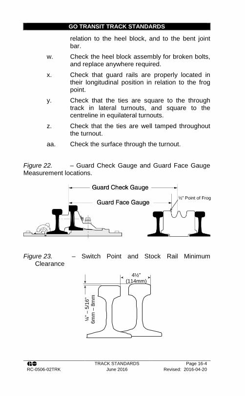
GO TRANSIT TRACK STANDARDS
TRACK STANDARDS Page 16-4 RC-0506-02TRK June 2016 Revised: 2016-04-20
relation to the heel block, and to the bent joint bar.
w. Check the heel block assembly for broken bolts, and replace anywhere required.
x. Check that guard rails are properly located in their longitudinal position in relation to the frog point.
y. Check that the ties are square to the through track in lateral turnouts, and square to the centreline in equilateral turnouts.
z. Check that the ties are well tamped throughout the turnout.
aa. Check the surface through the turnout.
Figure 22. – Guard Check Gauge and Guard Face Gauge Measurement locations.
Figure 23. – Switch Point and Stock Rail Minimum
Clearance
4½” (114mm)
¼” –
5/1
6”
6mm
– 8
mm
½” Point of Frog
GO TRANSIT TRACK STANDARDS
TRACK STANDARDS Page 16-5 RC-0506-02TRK June 2016 Revised: 2016-04-20
2. There must be no broken or bent clips or stop blocks.
Switch rods or connecting rods must not be excessively bent, broken or corroded to a depth exceeding 1/8 inch (3 mm).
3. Welding on connecting rods is not allowed. 4. Gauge at the point of the switch, heel of the switch, and
in the frog area is to be with ± ¼” (6mm) of standard gauge. Maintain the gauge in the remainder of the turnout per Priority Defect geometry limits.
5. Switch points are manufactured such that the running surface is 1/4” to 5/16” (6 to 8 mm) higher than the stock rail, as measured at the location where the distance between gauge face of stock rail and gauge face of switch point when tight against the stock rail is 4-1/2” (115 mm). When this vertical dimension is reduced by wear to 3/16” (5 mm), the location must be monitored for signs of wheel contact on the stock rail. Where contact is evident, the switch point must be renewed or the stock rail ground to restore the 1/4” to 5/16” (6 to 8 mm) dimension.
6. Stock rails can be worn more than ¼” (6mm) providing that the switch point is 3/16” (5mm) below the top of the stock rail as measured at the top of the radius at the end of the switch point.
7. On point ends which are chipped or broken the thickness must not exceed 3/16 inch (5 mm).
8. When the switch point or stock rail has sustained flow of more than 1/8” (3mm) causing the point to stand out from the stock rail, excess metal must be ground off to obtain proper fit.
9. Points and stock rails must be of the same size rail sections unless approved otherwise by the Rail Corridors Senior Manager of Track and Structures.
10. Gaps in switch points, regardless of size, are unacceptable. The points must fit tightly against the stock rail. a. Gaps between 1/16 in (1.5mm) to 1/8 in (3m)
must be repaired within 24 hours. The switch

GO TRANSIT TRACK STANDARDS
TRACK STANDARDS Page 16-6 RC-0506-02TRK June 2016 Revised: 2016-04-20
must be removed from service if one of the following conditions is also present: i. Locations with spiked rail braces; ii. Locations with bolted braces where
brace plate is spiked and there is evidence of plate movement;
iii. Locations in curves where the gap is on the diverging point;
iv. Locations where there is evidence of hanging or pumping ties;
v. Locations where the switch stand is not secure;
vi. Locations with Jackson switch stands; vii. Locations with gauge movement ahead
of the switch point; or viii. Locations with chipped points.
b. Gaps greater than 1/8 in (3mm) must be removed from service immediately.
c. Note: Locations where there is flange wear ahead of the switch points indicate that wheels are tracking outward and consequently, it will be easier for a wheel to climb or pick a switch point.
11. Where a different rail size is authorized, measure the switch point guards for wear as shown on the CN Standard Plan Drawing. If the wear is more than the wear limit allowed, the guard must be replaced.
12. Guard rail bolts and fasteners must be intact and tight. Guard rail wear surfaces must not be worn more than 5/8inch (16 mm).
13. Guard Check Gauge and the Guard Face Gauge shall be within the limits shown in Table 29.

GO TRANSIT TRACK STANDARDS
TRACK STANDARDS Page 16-7 RC-0506-02TRK June 2016 Revised: 2016-04-20
Table 29 – Guard Check Gauge and Guard Face Gauge
Class of Track
Minimum Guard Check Gaugea
Maximum Guard Face Gaugeb
1 54-1/8” (1375 mm) 53¼” (1352 mm) 2 54¼” (1378 mm) 53-1/8” (1349 mm)
3,4 54-3/8” (1381 mm) 53-1/8” (1349 mm) 5,6 54½” (1384 mm) c 53” (1346 mm)
a The distance from the gauge line of a frog to the guard line of its guard rail or guarding face, as measured across the track at right angles to the gauge line. See Figure 22. b The distance between guard lines as measured across the track at right angles to the gauge line. See Figure 22. c At points of heavy point frogs equipped with through gauge plates, 54 3/8 in (1381 mm)
14. Any loose or missing bolts must be replaced. 15. Lateral wear on a frog should not exceed 1/8 in (3 mm). 16. The flange-way depth measured from a plane across the
wheel bearing area of a frog on Class 1 track may not be less than 1 3/8 in (35 mm) or less than 1½ in (38 mm) on Class 2 through 6 track.
17. If a frog point is chipped, broken or worn more than 5/8 in (16 mm) down and 6 in (152 mm) back, operating speed over that frog may not be more than 10 mph.
18. If the tread portion of a frog casting is worn down more than 3/8 in (10 mm) below the original contour, operating speed over that frog may not be more than 10 mph.
19. Spring Frogs a. Clearance between the horn and hold-down
housing on spring frogs must not exceed ¼ in (6 mm), and the horn must not bind on the hold down housing.
b. Clearance between the bottom of the horn to the wear plate must not exceed 1/8 in (3mm).
c. Each spring must have a compressive force sufficient to hold the wing rail against the point rail.
GO TRANSIT TRACK STANDARDS
TRACK STANDARDS Page 16-8 RC-0506-02TRK June 2016 Revised: 2016-04-20
i. Note: the wing on 115 RE, 132 RE, and 136 RE spring frogs is designed to be open 3/8 in (10 mm) at the half inch point (13mm). The maximum opening is ¾ in (19 mm).
d. The wing rail must bear evenly on all base plates (check wear marks on the plates).
e. Check to ensure the outer edge of a wheel tread is not contacting the gauge side of the spring wing rail.
f. Similarly to the stock rail, if the outer edge of a wheel makes contact in a trailing movement, it can roll out the wing and derail a train. If the horns are doing their job significant wear would have to be present before a train wheel can make contact. i. There have been incidents caused by
tampers surfacing a turnout and bending the base plate enough to raise up the wing rail and cause a derailment. Always watch for evidence of a bent base plate especially if the wing rail stays open after a turnout is tamped.
g. The retarder, on frogs so equipped, must close completely with a cycle time from 1 minute to 3 minutes after opening.
20. On self-guarded frogs, check the wear on the raised guard. If the measurement from the raised guard on a self-guarded frog to the 5/8 in. (16mm) point on the gauge side of the frog point is more than 4 3/8 in. (111mm) restrict operating speed to not more than 10mph.
21. Bolts shall be retightened to refusal approximately 6 weeks after initial installation.
22. Ties that are plate cut more than 2¾” inches (70mm) or where the tie plate or rail can move laterally ½” (13mm) or more the tie will be considered defective. For further definition of defective ties see Track Standard Section 8 -.

GO TRANSIT TRACK STANDARDS
TRACK STANDARDS Page 16-9 RC-0506-02TRK June 2016 Revised: 2016-04-20
23. Ballast and proper drainage are necessary in order to maintain good surface and line through the turnout.
24. Make sure there is sufficient ballast and that the tie cribs are full.
25. Ensure that a good drainage ditch or structure is available on both sides of the track.
26. During winter months, tie cribs in the switch point area should be dug out.
27. Pay particular attention to the surface at the frog. 28. For more information on Turnout inspections see
Recommended Method 3500-1: Turnout Inspection 29. For more information on joint Track and S&C inspections
of power operated turnouts see Recommended Method 3500-0: Joint Inspection of Power Operated Turnouts.
16.6. Detailed Turnout Inspection
1. A detailed turnout inspection must include the measuring and recording of the following specified items: a. Track gauge measurements 5 to 10 ft. (1.5 – 3
m) ahead of the switch points, at the heel block, at the mid-point of curved closure rail, and at intervals throughout the diverging route behind the frog.
b. Guard check gauge measurement c. Guard face gauge measurement d. Switch Point Rise where contact is evident
(Vertical clearance between the switch point and the stock rail)
e. Heel Block assembly for surface and check bolts to confirm they are tight
f. Cross level measurements at locations 15.5ft (4724 mm) apart on both routes throughout the turnout.
g. Measurements obtained at required locations with track geometry vehicles meet the requirements of part a and part f above
GO TRANSIT TRACK STANDARDS
TRACK STANDARDS Page 16-10 RC-0506-02TRK June 2016 Revised: 2016-04-20
2. Each turnout and special track work must receive a detailed inspection at least annually, or per the minimum frequencies in Section 16.3
3. The switch stand should be checked for the following: a. The stand is securely fastened to the head block
ties. The stand should be securely fastened by proper head block bolts.
b. The head block ties are in good condition. c. The switch can be thrown with no excessive
wear in the handle. d. That the bushings to see that they are securely
in place and not excessively worn e. That the bushings and mast bearing areas are
well lubricated f. That the operating condition of the stand
4. The Eyebolt should be inspected as follows: a. Check eyebolt extensions. For 1½ in. (38mm)
eyebolt extension of 3/8 in (9.5mm) must be showing beyond the rear of the mast barrel. For 1¾ in (44.5mm) eyebolts a minimum of 7/8 in (22mm) must be showing
b. Check the relative movement between the handle and top casting, and between the top casting and mast. When relative movement becomes so great as to require excessive extension of the eyebolt from the mast barrel, the switch stand must be replaced.
c. Check if the eyebolt has been changed according to the following schedule: i. On primary lines, replace once every 6
years ii. On secondary lines, replace once every
9 years. 5. Inspect gauge plates, riser slide plates, turnout plates,
hook-twin tie plates, frog plates, guard rail plates, and tie plates as follows: a. Check for broken, bent, or missing plates
GO TRANSIT TRACK STANDARDS
TRACK STANDARDS Page 16-11 RC-0506-02TRK June 2016 Revised: 2016-04-20
b. Riser slide plates with the surface worn more than 1/8” (3mm)
c. Shoulder plates, or plates with cut rail seats for excessive rail
d. Gauge plates with defective insulation. This must be reported to the Signal Maintainer
e. Rails are properly seated in the gauge and riser slide plates.
f. Rail braces are tight and well driven, but not overdriven to the extent that the rail is canted inward
g. The riser side plates and spring frog plates are properly lubricated to permit free movement of switch points and spring wing rail
h. All other plates are properly seated with shoulders bearing firmly against the rail base
6. Measure cross level throughout the turnout at locations from 4 to 6 ties apart.
7. In addition to those measurements and requirements above, all the conditions in Section 16.5 “Turnout Walking Inspections” also apply to a detailed inspection.
8. For semi-automatic switches, the clamping force must be tested in addition to all other requirements above. Follow the procedure below: a. A No. 22 switch stand in good condition will
show a clamping force between 800 and 1400 pounds. If a switch stand reads a clamping force of 800 to 1000 lbs. consistently on one rail and 1200 to 1400 lbs consistently on the other that does not mean there is anything wrong with the stand. It just means that the connecting rod length is just a little different than ideal.
b. A stand that has had bad internal wear may very well show 1000 lbs. Clamping force on one rail, zero (0) on the other; then after being reversed a few more times may show zero (0) where it formerly showed 1000 lbs. and vice versa. The numbers will show no consistency from one trial
GO TRANSIT TRACK STANDARDS
TRACK STANDARDS Page 16-12 RC-0506-02TRK June 2016 Revised: 2016-04-20
to the next and no amount of adjustment of the connecting rod will make the clamping forces consistently come up to the 800 lbs. minimum.
c. There are two mechanical methods to check the pressure. One is an instrumented bolt that goes between the connecting rod and the #1 rod. The other is a clamp system that gives a pressure reading as you jack the point open. For consistency the clamp should be installed about 17 inches behind the point. The instrumented bolt gives readings a couple of hundred pounds below the clamp when tested on the same switch.
d. A reading below 800 lbs. With the instrumented bolt or 1,000 lbs. with the clamp system indicates that the stand should be immediately adjusted. If after adjustment it still cannot reach the necessary readings it should be changed. If you have a reading between 1,000 lbs. and 1200 lbs. with the clamp the stand should be rechecked on a monthly basis. Between 1200 lbs. and 1500 lbs. with the clamp should be checked twice a year. All stands should be checked once a year
e. If on inspection, ¼ inch wear is noted between the spindle and the top cover of the stand then a follow-up inspection with the “Instrumented Bolt” should be done to measure the clamping forces on each point. Anything greater than the ¼ inch (6 mm) is noted the stand should be changed out.
f. There is a date on the case of the Racor 22 stand. If this is older than ten years on a stand with a lot of use or any stand older than fifteen years shall be changed out.
g. If the instrumented bolt tests show excessive wear or other internal problems with the stand do not attempt to repair it in the field or in track, change out the stand. Racor 22 stands can be rebuilt by the manufacturer.

GO TRANSIT TRACK STANDARDS
TRACK STANDARDS Page 16-13 RC-0506-02TRK June 2016 Revised: 2016-04-20
9. Spring frogs require a detailed inspection at least twice a year. In addition to the other requirements, follow the procedure below: a. Check for breaks or cracks in the rails or
castings b. The spring frog is designed to work with the
wing closed during movement through the straight side. Even though a wheel should not drop in if the wing were to stay open, it should still close. Check the pressure on the spring (we do not use a pressure gage, but the spring should make the wing snap closed). Replace any broken springs in the spring box assembly. Occasionally, graphite-lubricate the base plate where the wing slides. Keep the flange-way between the wing and the fixed side of the frog clean of debris and ice and snow.
c. Check that all of the stops are in place and doing their job. If you see bent stops or mushrooming on the face of the stops, perform the following test: jack the wing open enough to place a 1 7/8 inch block in the flange-way. If you can slide a ¼ inch taper or step gage between the web of the rail and any of the stops they need to be repaired. They can be repaired by cutting them off and re-welding the stop closer or the welder can weld a repair plate to the face of the stop.
d. Our spring frogs are designed to be open 3/8 inch at the 1/2 inch point. But the spring wing rail should fit tightly against the frog along the entire length of the straight portion of the wing rail.
e. Make sure that all bolts are in place and tight. The proper bolt torque for 1 3/8 inch bolts is 2,500 ft./lbs., and 840 ft./lbs. For 1 inch bolts. Thin head bolts are used along the spring wing on spring frogs. These bolts are not visible in the normal closed position and should be inspected by jacking open the spring wing. Replace only with thin head bolts. Remember do not put any

GO TRANSIT TRACK STANDARDS
TRACK STANDARDS Page 16-14 RC-0506-02TRK June 2016 Revised: 2016-04-20
portion of your body between the spring wing and the fixed point without adequate blocking.
f. Inspect the anchor pattern. All switch and track ties should have solid box anchors for 200 feet behind the turnout, 200 feet ahead of the turnout and solid anchors through the turnout.
g. Check the side clearance between the hold down housings and the horns. If the closure rails have moved, it is possible to bind the rail open
h. Look for signs of ballast pumping, unstable subgrade, or tie condition that may allow the wing rail to gap open.
i. If your spring frog is equipped with a wing rail retarder (shock absorber), check its function monthly. The proper closing time of the wing rail should fall between 1 and 3 minutes. If the area under the retarder has evidence of oil being present, the retarder may have failed.
j. All snow and ice buildup near a spring frog should be removed. Every employee (track, S&C, B&S) that traverses these frogs should make a point of stopping and inspecting the frog and cleaning any ice and snow that is evident.
16.7. Failures in Spring Frogs
1. Despite their reliability, there can be failures in a spring frog. The most common failures and associated remedial actions and speed restrictions are listed below: a. Broken springs - Even with a missing spring the
frog opening should not be much bigger than an Rail Bound Manganese (RBM) frog. However with a broken spring that cannot be replaced before the next train, it is recommended that movement be only on the straight side. Speed should be limited to no more than 25 mph. A close inspection of the hold down horn clearance, the stops, and the guard check gage should be made. When replacing broken

GO TRANSIT TRACK STANDARDS
TRACK STANDARDS Page 16-15 RC-0506-02TRK June 2016 Revised: 2016-04-20
springs on a frog with double springs, replace both springs at the same time. When tightening a new spring, the bolts should be tightened until the spring is depressed 1 inch.
b. Broken fixed point. This condition is more dangerous than a broken point on a RBM frog. The wheel dropping down in the broken area may get low enough to catch the wing rail. The fixed point can be welded, but it is recommended that speed be no greater than 10 mph and each train watched over the frog until repaired
c. Excessive wear on the wing rail. It is somewhat unusual to see much flange wear on the wing rail, but still is a possibility. If there is flange wear in excess of 10 mm (3/8 inch), the frog should be considered for replacement. No slow order is necessary but a detailed inspection should be made to determine a possible cause of the wear.
d. Pumping in the heel and/or broken toe pan. Pumping in the heel is usually caused by bad surface conditions. If allowed to exist, these conditions can cause failure in the hold-down housing. A broken toe pan is a warning sign that something has gone wrong. There should very rarely be enough pressure to crack the toe pan. If a track inspector encounters this condition, they shall look for other problems like running rail or inadequate anchors, possibly even a car has been off in the frog.

GO TRANSIT RECOMMENDED METHODS
TRACK STANDARDS Page 16-16 RC-0506-02TRK June 2016 Revised: 2016-04-20
Recommended Method 3500-0: Joint Inspection of Power Operated Turnouts
Introduction This Recommended Method describes typical switch layout problems encountered at power operated switch locations that have a direct impact on the reliability of turnouts. Also described are appropriate corrective actions. The intent of this Recommended Method is to provide a guideline for use by Track Foreman, Track Supervisors, S&C Supervisors, and Signal Maintainers when conducting switch layout inspections. At least twice annually, it is recommended that switch layouts should be inspected jointly by Track and S&C maintainers. Power Switch Machines The primary function of power switch machines is to provide remote control of turnouts and to detect and indicate the position of the switch points. A typical switch machine is connected to switch points via the front rod and 1st switch rod, with connecting rods. In some cases helper rod assemblies are also provided. Figure 24. Left Handed Power Switch Machine Layout
GO TRANSIT RECOMMENDED METHODS
TRACK STANDARDS Page 16-17 RC-0506-02TRK June 2016 Revised: 2016-04-20
A typical switch machine contains a DC electric motor, gear drive, mechanical locking mechanism and indication contactors. It is adjusted internally and externally to throw the switch point, reverse or normal, and to detect if the switch points are within ¼ inch from the desired position. The ¼ inch adjustment is a safety requirement all railways in North America must adhere to. By default it is also a performance measure of the quality of the switch layout since there are several external factors involving the Track portion of the layout, which will directly impact the ability of the switch points to move freely and to seat properly against the stock rail. Switch Rollers The use of Schwihag switch rollers has been shown to significantly improve the performance of turnouts. These should be installed at problematic locations. Ordering information for rollers can be found on CN Standard Plan TS-390. As with all turnout hardware, Schwihag rollers should be inspected and maintained regularly. Refer to S&C General Instruction GI-409. References: GI-329, GI-409 and appropriate turnout plans Inspection Criteria The following tables identify some of problems typically encountered at power switch layouts, the probable causes and/or preventative maintenance procedures that can mitigate them, and the impacts on the switch machine.
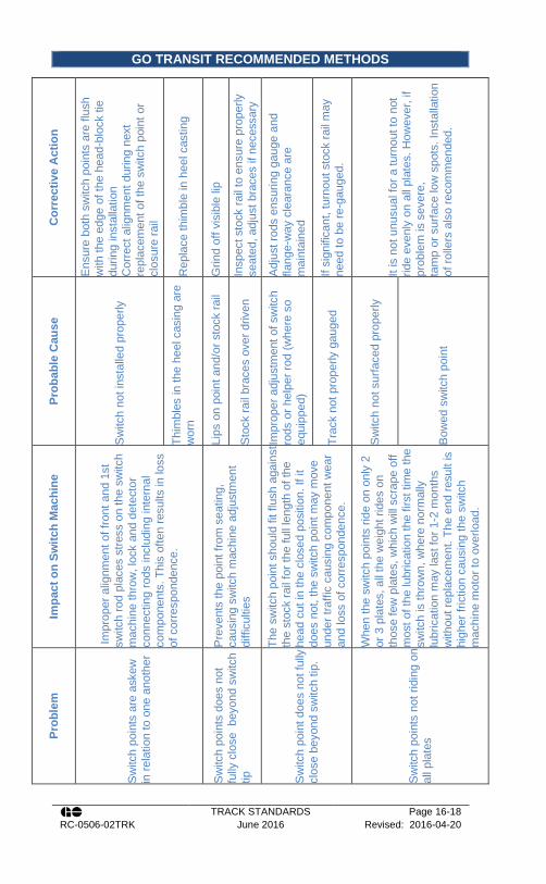
GO TRANSIT RECOMMENDED METHODS
TRACK STANDARDS Page 16-18 RC-0506-02TRK June 2016 Revised: 2016-04-20
Cor
rect
ive
Act
ion
Ens
ure
both
sw
itch
poin
ts a
re fl
ush
with
the
edge
of t
he h
ead-
bloc
k tie
du
ring
inst
alla
tion
Cor
rect
alig
nmen
t dur
ing
next
re
plac
emen
t of t
he s
witc
h po
int o
r cl
osur
e ra
il
Rep
lace
thim
ble
in h
eel c
astin
g
Grin
d of
f vis
ible
lip
Insp
ect s
tock
rail
to e
nsur
e pr
oper
ly
seat
ed, a
djus
t bra
ces
if ne
cess
ary
Adj
ust r
ods
ensu
ring
gaug
e an
d fla
nge-
way
cle
aran
ce a
re
mai
ntai
ned
If si
gnifi
cant
, tur
nout
sto
ck ra
il m
ay
need
to b
e re
-gau
ged.
It is
not
unu
sual
for a
turn
out t
o no
t rid
e ev
enly
on
all p
late
s. H
owev
er, i
f pr
oble
m is
sev
ere,
ta
mp
or s
urfa
ce lo
w s
pots
. Ins
talla
tion
of ro
llers
als
o re
com
men
ded.
Prob
able
Cau
se
Sw
itch
not i
nsta
lled
prop
erly
Thim
bles
in th
e he
el c
asin
g ar
e w
orn
Lips
on
poin
t and
/or s
tock
rail
Sto
ck ra
il br
aces
ove
r driv
en
Impr
oper
adj
ustm
ent o
f sw
itch
rods
or h
elpe
r rod
(whe
re s
o eq
uipp
ed)
Trac
k no
t pro
perly
gau
ged
Sw
itch
not s
urfa
ced
prop
erly
Bow
ed s
witc
h po
int
Impa
ct o
n Sw
itch
Mac
hine
Impr
oper
alig
nmen
t of f
ront
and
1st
sw
itch
rod
plac
es s
tress
on
the
switc
h m
achi
ne th
row
, loc
k an
d de
tect
or
conn
ectin
g ro
ds in
clud
ing
inte
rnal
co
mpo
nent
s. T
his
ofte
n re
sults
in lo
ss
of c
orre
spon
denc
e.
Pre
vent
s th
e po
int f
rom
sea
ting,
ca
usin
g sw
itch
mac
hine
adj
ustm
ent
diffi
culti
es
The
switc
h po
int s
houl
d fit
flus
h ag
ains
t th
e st
ock
rail
for t
he fu
ll le
ngth
of t
he
head
cut
in th
e cl
osed
pos
ition
. If i
t do
es n
ot, t
he s
witc
h po
int m
ay m
ove
unde
r tra
ffic
caus
ing
com
pone
nt w
ear
and
loss
of c
orre
spon
denc
e.
Whe
n th
e sw
itch
poin
ts ri
de o
n on
ly 2
or
3 p
late
s, a
ll th
e w
eigh
t rid
es o
n th
ose
few
pla
tes,
whi
ch w
ill sc
rape
off
mos
t of t
he lu
bric
atio
n th
e fir
st ti
me
the
switc
h is
thro
wn,
whe
re n
orm
ally
lu
bric
atio
n m
ay la
st fo
r 1-2
mon
ths
with
out r
epla
cem
ent.
The
end
resu
lt is
hi
gher
fric
tion
caus
ing
the
switc
h m
achi
ne m
otor
to o
verlo
ad.
Prob
lem
Sw
itch
poin
ts a
re a
skew
in
rela
tion
to o
ne a
noth
er
Sw
itch
poin
ts d
oes
not
fully
clo
se b
eyon
d sw
itch
tip
Sw
itch
poin
t doe
s no
t ful
ly
clos
e be
yond
sw
itch
tip.
Sw
itch
poin
ts n
ot ri
ding
on
all p
late
s

GO TRANSIT RECOMMENDED METHODS
TRACK STANDARDS Page 16-19 RC-0506-02TRK June 2016 Revised: 2016-04-20
Cor
rect
ive
Act
ion
Gra
phite
or l
ubric
ate
switc
h.
Rem
ove
exce
ss o
il an
d gr
it an
d lu
bric
ate
with
app
rove
d pr
oduc
t (g
raph
ite o
r WL1
91 lu
be).
Rem
ove
exce
ss o
il an
d gr
it an
d lu
bric
ate
with
app
rove
d pr
oduc
t (g
raph
ite o
r WL1
91 lu
be).
Cle
an s
witc
h ar
ea.
Han
d ta
mp
spot
loca
tions
or s
urfa
ce
who
le tu
rnou
t if f
easi
ble.
Rep
lace
bro
ken
tie p
late
s.
Prob
able
Cau
se
Lack
of g
raph
ite o
r oth
er
appr
oved
lubr
ican
t.
Sw
itch
has
been
lubr
icat
ed
usin
g en
gine
oil
or g
reas
e.
Eng
ine
sand
ers.
Rai
l grin
ding
s fro
m s
witc
h gr
inde
rs n
ot p
rope
rly re
mov
ed
afte
r grin
ding
.
Low
or h
angi
ng jo
ints
. In
suffi
cien
t tam
ping
Bro
ken
tie p
late
s.
Impa
ct o
n Sw
itch
Mac
hine
Lack
of l
ubric
atio
n ca
uses
too
muc
h fri
ctio
n be
twee
n po
ints
and
pla
tes
and
over
load
s th
e sw
itch
mac
hine
mot
or.
Usi
ng e
ngin
e oi
l or g
reas
e ga
ther
s di
rt,
filin
gs a
nd o
ther
grit
con
tribu
ting
to
frict
ion.
San
d on
sw
itch
plat
es in
crea
ses
frict
ion
and
caus
es th
e sw
itch
mac
hine
m
otor
to o
verlo
ad.
Rai
l grin
ding
s be
com
e m
agne
tized
due
to
grin
ding
act
ion
and
grin
ding
dep
osits
ad
here
to s
witc
h pl
ates
and
rods
by
pass
ing
the
insu
latio
n an
d sh
ort o
ut
the
OS
track
circ
uit,
resu
lting
in a
si
gnal
sys
tem
out
age
Exc
essi
ve m
ovem
ent c
an c
ause
sw
itch
mac
hine
adj
ustm
ents
to d
rift r
esul
ting
in lo
ss o
f cor
resp
onde
nce.
Prob
lem
Sw
itch
plat
es a
re n
ot
prop
erly
lubr
icat
ed.
(turn
outs
with
Sch
wih
ag
rolle
rs d
o no
t req
uire
lu
bric
atio
n)
San
d on
sw
itch
plat
es.
Rai
l grin
ding
s on
sw
itch
plat
es a
nd in
crib
.
Poo
r sur
faci
ng.

GO TRANSIT RECOMMENDED METHODS
TRACK STANDARDS Page 16-20 RC-0506-02TRK June 2016 Revised: 2016-04-20
Cor
rect
ive
Act
ion
Lubr
icat
e M
JS c
lips
imm
edia
tely
.
Ens
ure
MJS
clip
s ar
e lu
bric
ated
re
gula
rly in
acc
orda
nce
with
GI-
409.
Che
ck a
nd re
plac
e sh
ims
Rep
lace
insu
lato
rs.
Ens
ure
track
app
lianc
es a
re in
spec
ted
regu
larly
in a
ccor
danc
e w
ith G
I-332
.
Prob
able
Cau
se
MJS
clip
s ar
e no
t pro
perly
in
stal
led
or lu
bric
ated
.
Bro
ken
or fa
tigue
d in
sula
tors
on
front
rods
, sw
itch
rods
, gau
ge
rods
, gau
ge p
late
s, in
sula
ted
join
ts, a
nd in
sula
ted
duct
wor
k.
Ref
er to
S&
C G
ener
al
Inst
ruct
ion
GI-3
32.
Impa
ct o
n Sw
itch
Mac
hine
MJS
clip
s w
hich
are
adj
uste
d to
o tig
ht
and
/ or n
ot lu
bric
ated
will
resu
lt in
hi
gher
fric
tion
durin
g sw
itch
mov
emen
t ca
usin
g ov
erlo
adin
g of
the
switc
h m
achi
ne.
Wor
n M
JS c
lips
cont
ribut
e to
sw
itch
poin
t mis
alig
nmen
t and
loss
of
corre
spon
denc
e.
Not
e: R
ocke
r clip
s ar
e us
ed in
new
er
turn
outs
inst
ead
of M
JS c
lips,
and
re
quire
no
lubr
icat
ion.
Faile
d in
sula
tors
will
shor
t out
the
OS
tra
ck c
ircui
t, re
sulti
ng in
a s
igna
l sy
stem
out
age.
Prob
lem
Wor
n, im
prop
erly
adj
uste
d or
dry
MJS
clip
s.
Faile
d in
sula
tor.
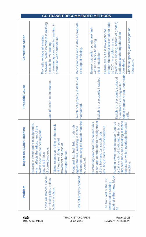
GO TRANSIT RECOMMENDED METHODS
TRACK STANDARDS Page 16-21 RC-0506-02TRK June 2016 Revised: 2016-04-20
Cor
rect
ive
Act
ion
Pro
mpt
ly re
plac
e al
l mis
sing
ha
rdw
are.
Whe
n ha
rdw
are
is m
issi
ng
it re
sults
in o
verlo
adin
g of
rem
aini
ng c
ompo
nent
s re
sulti
ng in
pr
emat
ure
wea
r and
failu
re.
Rep
ositi
on ti
es a
nd in
stal
l app
ropr
iate
tie
stra
ps if
mis
sing
.
Ens
ure
that
sw
itch
poin
ts a
re fl
ush
with
hea
d bl
ock
tie d
urin
g in
itial
inst
alla
tion.
Ens
ure
ever
y tie
is b
ox a
ncho
red
thro
ugh
the
turn
out a
nd o
n ei
ther
sid
e by
200
’. In
pro
blem
are
as
(dire
ctio
nal r
unni
ng, b
otto
m o
f gra
des)
ad
ditio
nal a
ncho
ring
shou
ld b
e co
nsid
ered
.
Che
ck ti
e sp
acin
g an
d re
adju
st a
s ne
cess
ary.
Prob
able
Cau
se
Lack
of s
witc
h m
aint
enan
ce.
Sw
itch
not p
rope
rly in
stal
led
or
mai
ntai
ned.
Sw
itch
is n
ot p
rope
rly in
stal
led.
Sw
itch
is n
ot p
rope
rly s
urfa
ced
or a
ncho
red
caus
ing
switc
h po
ints
to m
ove
or ru
n un
der t
rain
tra
ffic.
Impa
ct o
n Sw
itch
Mac
hine
Res
ults
in s
witc
h po
int m
isal
ignm
ent,
whi
ch a
ffect
s th
e ad
just
men
t of t
he
switc
h m
achi
ne c
onne
ctin
g ro
ds
resu
lting
in lo
ss
of c
orre
spon
denc
e.
Allo
ws
exce
ssiv
e ro
lling
of t
he s
tock
ra
il he
ad re
sulti
ng in
poi
nt
mov
emen
t and
loss
of
corre
spon
denc
e.
Fron
t and
1st
, 2nd
, 3rd
, … ro
ds ru
b ag
ains
t the
ties
, res
ultin
g in
fric
tion
resi
stan
ce c
ausi
ng th
e sw
itch
mac
hine
to
ove
rload
.
Fluc
tuat
ing
tem
pera
ture
s ca
uses
rails
to
run
and
cont
ribut
es to
mis
alig
nmen
t of
the
front
and
1st
sw
itch
rods
re
sulti
ng in
loss
of c
orre
spon
denc
e.
Run
ning
sw
itch
poin
ts c
ause
fron
t rod
or
1st
sw
itch
rod
to d
ig in
to th
e 1s
t or
2nd
head
blo
ck ti
es re
sulti
ng in
fric
tion
resi
stan
ce, w
hich
ove
rload
s th
e sw
itch
mac
hine
.
Prob
lem
Loos
e ra
il br
aces
. Loo
se
or m
issi
ng c
lips,
spi
kes,
bo
lts o
r anc
hors
.
Ties
not
pro
perly
spa
ced
The
front
rod
or th
e 1s
t sw
itch
rod
is ru
bbin
g ag
ains
t eith
er h
ead
bloc
k tie
.

GO TRANSIT RECOMMENDED METHODS
TRACK STANDARDS Page 16-22 RC-0506-02TRK June 2016 Revised: 2016-04-20
Cor
rect
ive
Act
ion
Rep
lace
hea
d bl
ock
ties
as re
quire
d.
Con
side
ratio
n sh
ould
be
give
n to
in
stal
ling
new
gau
ge p
late
s w
ith th
e at
tach
ed s
witc
h m
achi
ne p
late
(CN
Sta
ndar
d P
lan
TS-
520)
Ens
ure
adeq
uate
and
app
ropr
iate
ba
llast
leve
ls in
all
crib
s,
prov
idin
g sp
ace
for t
hrow
rods
to
mov
e w
here
app
licab
le.
All
exce
ss
balla
st th
at c
ould
inte
rfere
with
sw
itch
poin
t mov
emen
t sho
uld
be s
wep
t cl
ear.
Re-
inst
all s
traps
and
tigh
ten
lag
scre
ws
ASA
P.
Re-
alig
n he
lper
hei
ght i
f pos
sibl
e;
cons
ider
repl
acem
ent w
ith a
hel
per
cran
k of
cor
rect
he
ight
.
Prob
able
Cau
se
Lack
of s
witc
h m
aint
enan
ce.
Lack
of s
witc
h m
aint
enan
ce.
Sw
itch
not p
rope
rly in
stal
led.
Lag
scre
ws
pulle
d lo
ose.
Inco
rrect
hei
ght o
f hel
per c
rank
.
Impa
ct o
n Sw
itch
Mac
hine
This
resu
lts in
the
fast
enin
g bo
lts
secu
ring
the
switc
h m
achi
ne a
nd
exte
nded
gau
ge p
late
to th
e he
ad
bloc
ks to
loos
en re
sulti
ng in
loss
of
switc
h m
achi
ne a
djus
tmen
t.
Exc
essi
ve b
alla
st in
crib
and
aro
und
mov
ing
parts
can
cre
ate
addi
tiona
l re
sist
ance
to th
row
resu
lting
in s
witc
h m
achi
ne o
verlo
adin
g.
Mis
alig
nmen
t of t
ies
resu
lts in
rods
ev
entu
ally
rubb
ing
agai
nst t
he ti
es,
caus
ing
the
switc
h m
achi
ne m
otor
to
over
load
.
Exc
essi
ve d
own
stro
ke o
f hel
per c
rank
re
sults
in e
xces
sive
forc
e on
the
switc
h m
achi
ne.
Prob
lem
Dam
aged
or w
orn
head
bl
ock
ties.
Exc
essi
ve b
alla
st in
crib
.
Tie
stra
ps a
t sw
itch
or
help
er c
rank
loos
e or
not
in
pla
ce.
Hel
per c
rank
not
pro
perly
al
igne
d.

GO TRANSIT RECOMMENDED METHODS
TRACK STANDARDS Page 16-23 RC-0506-02TRK June 2016 Revised: 2016-04-20
Cor
rect
ive
Act
ion
Rep
lace
or r
epai
r dam
aged
co
mpo
nent
s A
SAP.
Ens
ure
hard
war
e is
insp
ecte
d re
gula
rly in
acc
orda
nce
with
GI-
329(
a), 3
29(b
)(3) a
nd 4
09, a
nd th
at
nece
ssar
y ad
just
men
ts a
re
mad
e pr
ompt
ly a
s re
quire
d.
Ens
ure
bolts
are
insp
ecte
d re
gula
rly in
ac
cord
ance
with
GI-
329(
a) a
nd a
djus
t im
med
iate
ly.
Inst
all n
ew s
witc
h pl
ates
Ens
ure
fast
enin
g ha
rdw
are
is
insp
ecte
d re
gula
rly in
ac
cord
ance
with
GI-3
29(a
) and
GI-
409,
and
adj
ust o
r rep
lace
im
med
iate
ly a
s re
quire
d.
Prob
able
Cau
se
Trac
k m
achi
nes
and
othe
r he
avy
wor
k eq
uipm
ent d
rive
over
hel
per
rods
.
Impr
oper
ly a
djus
ted
help
ers.
Lack
of s
witc
h m
achi
ne
mai
nten
ance
.
Dam
aged
or w
orn
head
blo
ck
ties
(see
abo
ve).
Sw
itch
poin
t bol
t cot
ter k
eys,
lo
ck w
ashe
rs, l
ag s
crew
s br
oken
or
loos
e.
Impa
ct o
n Sw
itch
Mac
hine
Ben
t or b
roke
n he
lper
rods
resu
lt in
ad
ditio
nal f
orce
requ
ired
to m
ove
the
poin
ts a
nd th
eref
ore
high
er m
otor
cu
rrent
whi
ch c
an re
sult
in s
witc
h m
achi
ne m
otor
ove
rload
. Thi
s m
ay
also
lead
to a
dditi
onal
sw
itch
poin
t w
ear.
Exc
essi
ve p
ress
ure
on th
e he
lper
rod
can
prev
ent t
he s
witc
h fro
m lo
ckin
g up
. Th
e he
lper
onl
y ne
eds
to m
ove
the
back
of t
he p
oint
into
pro
per p
ositi
on.
Res
ults
in lo
ss o
f sw
itch
mac
hine
ad
just
men
t.
Loos
e sw
itch
com
pone
nts
caus
e sw
itch
poin
t mis
alig
nmen
t res
ultin
g in
sw
itch
mac
hine
mot
or o
verlo
adin
g an
d lo
ss o
f cor
resp
onde
nce.
Prob
lem
Dam
aged
hel
per r
od
asse
mbl
y.
Ove
r-tig
hten
ing
of h
elpe
r ro
ds.
Loos
e fa
sten
ing
bolts
se
curin
g sw
itch
mac
hine
.
Mis
sing
or l
oose
fast
enin
g ha
rdw
are.

GO TRANSIT RECOMMENDED METHODS
TRACK STANDARDS Page 16-24 RC-0506-02TRK June 2016 Revised: 2016-04-20
Cor
rect
ive
Act
ion
Ens
ure
a ge
nera
l ins
pect
ion
in
acco
rdan
ce w
ith G
I-329
(a) i
s pe
rform
ed re
gula
rly a
nd n
eces
sary
ad
just
men
ts o
r rep
lace
men
ts a
re
perfo
rmed
AS
AP.
Ens
ure
wea
r pla
tes
are
insp
ecte
d re
gula
rly in
ac
cord
ance
with
GI-3
29(c
)(4),
and
repl
ace
as re
quire
d.
Ens
ure
nozz
les
are
corre
ctly
inst
alle
d an
d in
spec
ted
regu
larly
.
Pla
n fo
r ref
urbi
shm
ent o
f SC
Ds
as
requ
ired.
Ens
ure
regu
lar i
nspe
ctio
ns o
f sno
w
clea
ring
devi
ces
are
perfo
rmed
.
Pla
n fo
r ref
urbi
shm
ent o
f SC
Ds
as
requ
ired.
Prob
able
Cau
se
Lack
of s
witc
h m
aint
enan
ce.
Lack
of s
witc
h m
aint
enan
ce.
Impr
oper
ly in
stal
led
nozz
les.
Poo
rly a
djus
ted
or m
aint
aine
d sn
ow c
lear
ing
devi
ce.
Inco
rrect
type
of s
now
cle
arin
g de
vice
for l
ocal
env
ironm
ent.
Impa
ct o
n Sw
itch
Mac
hine
Exc
essi
ve lo
st m
otio
n be
twee
n th
e po
ints
and
sw
itch
mac
hine
thro
w ro
d,
lock
rod,
or p
oint
det
ecto
r rod
can
re
sult
in lo
ss o
f cor
resp
onde
nce,
or
failu
re to
pro
perly
det
ect a
n op
en p
oint
.
A g
ap o
f mor
e th
an .0
60” b
etw
een
the
top
of th
e po
int d
etec
tor r
od a
nd G
RS
M
odel
5 s
witc
h m
achi
ne h
ousi
ng w
ill
caus
e ex
cess
ive
mot
ion
of th
e po
int
dete
ctor
rod
resu
lting
in lo
ss o
f co
rresp
onde
nce.
Sno
w c
lear
ing
devi
ce n
ozzl
es m
ust b
e in
stal
led
with
2 to
3 in
ches
of c
lear
ance
to
the
poin
t. Fa
ilure
to d
o so
can
resu
lt in
unr
elia
ble
switc
h lo
ckin
g.
Exc
essi
ve s
now
and
ice
build
up c
an
crea
te o
bstru
ctio
n or
incr
ease
re
sist
ance
to th
row
resu
lting
in s
witc
h ov
erlo
adin
g.
Prob
lem
Loos
e or
wor
n ba
ll en
d po
int l
ugs,
rod
bush
ings
, be
ar p
aws,
cle
vise
s, b
ent
poin
t det
ecto
r or l
ock
rods
.
Exc
essi
ve w
ear o
f poi
nt
dete
ctor
wea
r pla
tes
on
GR
S m
achi
nes.
Sno
w c
lear
ing
devi
ce
nozz
les
obst
ruct
ing
poin
ts.
Sno
w a
nd ic
e bu
ildup
un
der b
ase
of p
oint
s.

GO TRANSIT RECOMMENDED METHODS
TRACK STANDARDS Page 16-25 RC-0506-02TRK June 2016 Revised: 2016-04-20
Recommended Method 3500-1: Turnout Inspection
Items to Check Regulatory Requirements TS Requirements
Ballast and Drainage
• must restrain track laterally, vertically and horizontally (for thermal and mechanical loads)
• provide adequate drainage
• maintain proper cross-level, surface and alignment
• Cribs full except for switch point area for drainage as required in winter months.
• Ballast shoulder not less than 12”.
• No standing water, or indications of it.
Line, gauge, surface, and cross level
TC Track Safety Rules Part II - C II, C III, C VI
• Per Track Standard Section 15 -
Ties TC Track Safety Rules Part II - D II
• Sound and holding spikes.
• Properly spaced and square to track.
• Firmly tamped for 16” on each side of mainline and turnout rails
• Head block ties tamped as above with no voids under remainder of tie
Plates TC Track Safety Rules Part II - D VI
• None broken. • None missing. • Not worn in excess of 1/8
inch (3 mm).
Rails (Including switch rails, closure rails, stock rails, and frog rails)
• Stock rails securely seated in switch plates, not canted by badly adjusted rail braces.
TC Track Safety Rules Part II - D XII (a)
• Note rail condition such as rust streaks, ordinary breaks, vertical or horizontal split heads, engine burns, broken bases, crushed heads.
• End batter or mismatch not exceeding 1/8 “ (3 mm) at toe of frog and heel of frog and switch.
Fasteners
• The fastenings must be intact and maintained so as to keep the components firmly in place.
TC Track Safety Rules Part II - D XI (a)
• Fully spiked (except hook twin tie plates which will have only one spike per plate end) or fastened with tie screws and Pandrol clips.
• Spikes fully driven, or timber tie screws drawn down.

GO TRANSIT RECOMMENDED METHODS
TRACK STANDARDS Page 16-26 RC-0506-02TRK June 2016 Revised: 2016-04-20
Castings
• No broken castings (heel blocks, anchor blocks, rail braces, etc.) except frog casting heel extension.
Bolts TC Track Safety Rules Part II - D V
• None loose, broken or missing.
• All tight (torque per Track Standard Section 12.4)
• Spring washers, flat washers or cotter pins present as required
Rail Anchors
• Classes 4 through 6 track must be equipped with rail anchors through and on each side of track crossings and turnouts, to restrain rail movement affecting switch points and frogs.
TC Track Safety Rules Part II - D XI (a)
• On main track or in CWR territory: o Fully anchored on both
tracks through turnouts (except where anchors will interfere with switch points).
o Fully anchored for 200 ft. in both directions beyond the turnout.
• On other tracks, sufficient number of rail anchors to restrain rail movement affecting switch points and frogs.
Insulation • In place and functional.
Lubrication
• Each switch point must fit its stock rail properly
• Lateral or vertical movement of a stock rail in the switch plates or of the switch plate on a tie must not adversely affect the fit of the switch point to the stock rail.
TC Track Safety Rules Part II - D XII (b)
• Slide plates clean and lubricated.
• Switch stands lubricated. • Spring assemblies and
base plates of spring frogs lubricated.
• Special assemblies such as pipe connected derails and auxiliary throws, lubricated.
Switch Point Fit
• Unusually chipped or worn switch points must be repaired or replaced.
• Metal flow must be removed to ensure proper closure
TC Track Safety Rules Part II - D XII (b)
• Points not overhanging gauge plate nor more than one inch back from front edge.
• The entire planed portion of the rail head on switch points fits tight against stock rails.
• Point of switch rail not less than 1/2 inch below top of stock rail.
• No sharp kinks, loose bolts or rivets
• No broken, bent or weld

GO TRANSIT RECOMMENDED METHODS
TRACK STANDARDS Page 16-27 RC-0506-02TRK June 2016 Revised: 2016-04-20
repaired clips or stop blocks.
• No switch or connecting rods to be bent or broken or corroded to a depth exceeding 1/8 inch (3 mm.)
• No weld repaired switch or connecting rods
Thickness / Flow
• Unusually chipped or worn switch points must be repaired or replaced.
• Metal flow must be removed to ensure proper closure
TC Track Safety Rules Part II - D XII (b), (h)
• On point ends which are chipped or broken the thickness must not exceed 3/16” (5 mm).
• Flow not exceeding 1/16” (1.5 mm) on switch point or gauge side of stock rail.
Running Surface
• Each switch must be maintained so that the outer edge of the wheel tread cannot contact the gauge side of the stock rail.
TC Track Safety Rules Part II - D XII (c), (h)
• Running surface of points should be 1/4” (6 mm) above stock rail. When less than 3/16” (5 mm) above the stock rail monitor for signs of contact.
Heel of Switch
• The heel of each switch rail must be secure and the bolts in each heel must be kept tight.
TC Track Safety Rules Part II - D XII (d)
• No missing, loose , bent or broken bolts
• No missing cotter pins, if required.
Switch Locks / Keepers
• Each throw lever must be maintained so that it cannot be operated with the lock or keeper in place.
TC Track Safety Rules Part II - D XII (f)
• Main track switches must be secured with an approved switch lock.
• Other track switches secured with lock or keeper, as required.
Switch Stand (Inspection / Adjust)
• Each switch stand and connecting rod must be securely fastened and operable without excessive lost motion.
TC Track Safety Rules Part II - D XII (e)
• In good operating condition. Rigid stands must have 1 3/4” crank eyes.
• Switch handles of rigid switch stands cannot be placed in locking position with normal pressure when 1/8” (3 mm) shim placed between point and stock rail at first rod

GO TRANSIT RECOMMENDED METHODS
TRACK STANDARDS Page 16-28 RC-0506-02TRK June 2016 Revised: 2016-04-20
(check for lost motion). • The throw at the No. 1 rod
and the auxiliary throw rod, where applicable, will be according to plan.
• All switch rod and connecting rod bolts, except those under switch stand, with nuts up and protected by cotter pins.
Switch Targets
• Each target must be clearly visible at all times.
TC Track Safety Rules Part II - D XII (e)
• Required targets per standard in place, visible, in good condition and displaying proper indication.
General
• If a frog point is chipped, broken or worn more than 5/8” (16 mm) down and 6” (150 mm) back, operating speed over that frog may not be more than 10 mph.
• If the tread portion of a frog casting is worn down more than 3/8” (10 mm) below the original contour, operating speed over that frog may not be more than 10 mph.
TC Track Safety Rules Part II - D XIII (b), (c )
• heel risers not broken nor flowed sufficient to bow point rails.
• point and adjacent running surfaces not broken, chipped or excessively worn: 3/8” maximum
• good line on through track.
• No broken , loose, bent or broken plates
Flange-ways
• Flange-way depth: o on Class 1 track may
not be less than 1 3/8” (35 mm) or
o on Classes 2 through 6 track not less than 1 1/2” (38 mm).
• Flange-ways must be at least 1 1/2” (38 mm) wide
TC Track Safety Rules Part II - D XIII (a)
• Clear of foreign objects. • Not less than 1-1/2” deep. • Not less than 1-3/4” wide.
Spring Frogs
• Clearance between horn and hold-down housing not exceeding 1/4 inch (6 mm)
• Each spring must have a tension sufficient to hold the wing rail against the point rail.
• The outer edge of a wheel tread may not contact the
• Horn not binding on hold down housing.
• Each spring must have sufficient compression to hold the wing rail against the point rail.
• Note: wing rail of 115 Ib. and 132/136 Ib. spring frogs is designed to be open 3/8 inch at the half
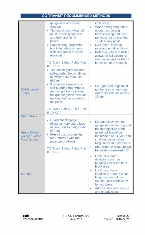
GO TRANSIT RECOMMENDED METHODS
TRACK STANDARDS Page 16-29 RC-0506-02TRK June 2016 Revised: 2016-04-20
gauge side of a spring wing rail.
• The toe of each wing rail must be solidly tamped and fully and tightly bolted.
• Each (spring) frog with a bolt hole defect or head-web separation must be replaced.
TC Track Safety Rules Part II - D XIV
inch point). • When spring wing rail is
open, the opening between wing and point rail must not be less than 1 3/4” at any point.
• No broken, loose or missing hold down bolts
• Retarder, where installed, allows for full closure of wing rail in greater than 1 but less than 3 minutes.
Self-Guarded Frogs
• The raised guard rail on a self-guarded frog shall not be worn more than 3/8” (9.5 mm).
• If repairs are made to a self-guarded frog without removing it from service, the guarding face must be restored before rebuilding the point.
TC Track Safety Rules Part II - D XV
• Self-guarded frogs must not be used on turnouts where speeds will exceed 15 mph.
Guard Rails
Guard Check Gauge / Guard Face Gauge
• Guard check gauge (distance from guard face of guard rail to gauge side of frog)
• Free of obstructions that may interfere with the passage of wheels
TC Track Safety Rules Part II - D XVI
• Distance between the gauge side of the frog and the bearing side of the guard rail should be maintained at 54 5/8”, and shall not be less than Regulatory Requirements.
• Side wear on raised guard bar must not exceed 5/8”
Surface
• Look for surface deviations such as hanging ties at the heel block area
• Look for surface conditions about 1-2 car lengths ahead of the switch. Look particularly for low joints
• Address drainage issues and muddy spots

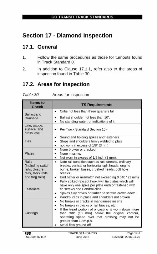
GO TRANSIT TRACK STANDARDS
TRACK STANDARDS Page 17-1 RC-0506-02TRK June 2016 Revised: 2016-04-20
Section 17 - Diamond Inspection
17.1. General
1. Follow the same procedures as those for turnouts found in Track Standard 0.
2. In addition to Clause 17.1.1, refer also to the areas of inspection found in Table 30.
17.2. Areas for Inspection
Table 30 Areas for inspection
Items to Check TS Requirements
Ballast and Drainage
• Cribs not less than three quarters full
• Ballast shoulder not less than 10”. • No standing water, or indications of it.
Line, gauge, surface, and cross level
• Per Track Standard Section 15 -
Ties • Sound and holding spikes and fasteners • Stops and shoulders firmly welded to plate • not worn in excess of 1/8” (3mm)
Plates • None broken or cracked • None missing. • Not worn in excess of 1/8 inch (3 mm).
Rails (Including switch rails, closure rails, stock rails, and frog rails)
• Note rail condition such as rust streaks, ordinary breaks, vertical or horizontal split heads, engine burns, broken bases, crushed heads, bolt hole breaks.
• End batter or mismatch not exceeding 0.040 “ (1 mm)
Fasteners
• Fully spiked (except hook twin tie plates which will have only one spike per plate end) or fastened with tie screws and Pandrol clips.
• Spikes fully driven or timber tie screws drawn down. • Pandrol clips in place and shoulders not broken
Castings
• No breaks or cracks in manganese inserts • No breaks in blocks or rail braces, etc. • If the tread portion of a casting is worn down more
than 3/8” (10 mm) below the original contour, operating speed over that crossing may not be greater than 10 m.p.h.
• Metal flow ground off
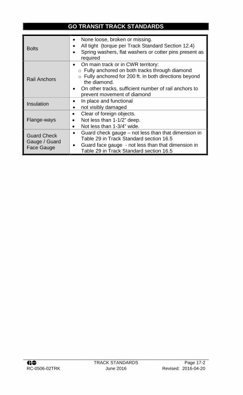
GO TRANSIT TRACK STANDARDS
TRACK STANDARDS Page 17-2 RC-0506-02TRK June 2016 Revised: 2016-04-20
Bolts
• None loose, broken or missing. • All tight (torque per Track Standard Section 12.4) • Spring washers, flat washers or cotter pins present as
required
Rail Anchors
• On main track or in CWR territory: o Fully anchored on both tracks through diamond o Fully anchored for 200 ft. in both directions beyond
the diamond. • On other tracks, sufficient number of rail anchors to
prevent movement of diamond
Insulation • In place and functional • not visibly damaged
Flange-ways • Clear of foreign objects. • Not less than 1-1/2” deep. • Not less than 1-3/4” wide.
Guard Check Gauge / Guard Face Gauge
• Guard check gauge – not less than that dimension in Table 29 in Track Standard section 16.5
• Guard face gauge - not less than that dimension in Table 29 in Track Standard section 16.5

GO TRANSIT TRACK STANDARDS
TRACK STANDARDS Page 18-1 RC-0506-02TRK June 2016 Revised: 2016-04-20
Section 18 - Electronic Track Inspection
18.1. General Information
1. An Electronic Track Geometry Inspection vehicle is an automated track inspection vehicle used to measure, calculate and record geometric parameters of the track.
2. Two types of track geometry inspection vehicles, defined below, can be used to measure and evaluate track geometry. a. Light Geometry Inspection Vehicle (LGIV)
i. must be capable of measuring:
• Alignment / Curvature
• Superelevation / Cross Level
• Unloaded Gauge
• Railway Track Safety Rules and parameters calculated from these measurements
ii. GO Transit typically uses, through contracted services, the Andian truck as a LGIV
b. Heavy Geometry Inspection Vehicle (HGIV) i. must have a vertical wheel load
minimum of 10,000 lbs (4,545 kg) and be capable of measuring:
• Surface / Longitudinal Profile
• Alignment / Curvature
• Super Elevation / Cross Level
• Loaded and Unloaded Gauge*
• Railway Track Safety Rules and parameters calculated from these measurements
GO TRANSIT TRACK STANDARDS
TRACK STANDARDS Page 18-2 RC-0506-02TRK June 2016 Revised: 2016-04-20
* L/V ratios from 0.67 and less than 0.7 are acceptable. For safety reasons, test loads will be turned off when actual loaded gauge readings reach 58 inches (1.5 inches wide).
ii. GO Transit operates the Integrated Rail Inspection System (I.R.I.S.) truck for this purpose. This truck is also equipped with measurement capabilities for:
• Rail wear
• Ultrasonic rail testing iii. Measurements obtained with this
vehicle are considered dynamic geometry measurements representative of the track in a loaded condition.
3. A Rail Flaw Inspection is a continuous search for internal defects. a. As previously mentioned in 18.1.2.b.ii, GO
Transit uses the I.R.I.S. truck to complete their Rail Flaw inspections.
18.2. Types of Test Methods
1. There are three types of test methods a. Track Geometry and Gauge Measurements b. Rail Surface and Internal Flaw Recordings
Testing c. Rail Wear Measurement
2. Geometry and Rail Wear typically occur simultaneously. 3. On the I.R.I.S. truck, all three tests can occur
simultaneously. However, however when run simultaneously, these tests are limited to the most restrictive speed of the equipment.
18.3. Frequency of Testing
1. Minimum track inspection frequencies shall be as outline in the Transport Canada Track Safety Rules, but not less

GO TRANSIT TRACK STANDARDS
TRACK STANDARDS Page 18-3 RC-0506-02TRK June 2016 Revised: 2016-04-20
than in Appendix A – Track inspection frequencies in Table 39 and Table 40
2. An automated geometry inspection is required for all tracks. a. Class 1 track with an annual tonnage less than 5
MGT and Yard tracks can be tested using an LGIV.
3. If a portion of track cannot be inspected at the required interval, the Rail Corridors Senior Manager of Track and Structures may permit a reduced frequency up to that mandated by Transport Canada
4. Should the Transport Canada required interval not be met, the railway must, before the expiration of the time or tonnage limits: a. Inspect that segment of track with a LGIV and
be governed by the results of that inspection or perform an additional visual inspection per week until the required track geometry inspection frequency can be met;
b. In the case of Class 3 to Class 5 track the next required track geometry inspected must be completed with a heavy geometry inspection vehicle;
c. Reduce class of track to bring the track into compliance until such time as a valid track geometry inspection can be made; or
d. If a portion of a crossover cannot be inspected at the required interval, the railway must, before the expiration of time or tonnage limits, perform a detailed inspection of both turnouts and the track in between.
5. A rail flaw inspection is required for all tracks. a. Yard tracks, also require rail flaw inspections. b. Where a test on the above cannot be performed
the yard track speed cannot exceed 10mph. 6. If a valid search for internal defects cannot be conducted
for any reason, the Rail Corridors Senior Manager of

GO TRANSIT TRACK STANDARDS
TRACK STANDARDS Page 18-4 RC-0506-02TRK June 2016 Revised: 2016-04-20
Track and Structures may permit a reduced frequency up to that mandated by Transport Canada.
7. Should the Transport Canada required interval not be met, the railway must, before the expiration of the time or tonnage limits: a. Conduct a valid search for internal defects, or b. Reduce class of track per Section 18.4.
18.4. Rail Flaw Detection (Ultra-Sonic)
1. Rail on all main tracks, including crossovers and sidings contained on such lines will be ultrasonically tested (UTT). This policy also covers the following two areas: a. Used rail purchased from 3rd parties. b. Rail removed from track.
2. A qualified person shall undertake ultrasonic inspection of rail. Rails that have been ultrasonically tested will be kept segregated from those that have not been tested (preferably on separate rail racks) and will display the markings as detailed below.
3. As grease interferes with proper ultrasonic testing, all lubricators must be shut off sufficiently in advance of any Ultrasonic Rail Testing to ensure no grease is present. Lubricators must be reactivated immediately after testing.
4. Rails to be tested out of track must be wire brushed to remove rust and scale. Rails shall have a complete ultrasonic test for the full length of the rail. Ultrasonic tests will be undertaken using equipment capable of traversing single rails. Such equipment is not capable of testing the ends of the rail. Therefore, both rail ends must be tested using portable hand test units. Where the rail head has surface defects that prevent the ultrasonic inspection of the rail, such defects must be cut out or the rail scrapped.
5. Rails tested under this policy and found to be free of internal defects will be either identified by the letters “UTT” (for Ultrasonically Tested) or “UTC” (for Ultrasonically Certified), depending on the rails origin.
GO TRANSIT TRACK STANDARDS
TRACK STANDARDS Page 18-5 RC-0506-02TRK June 2016 Revised: 2016-04-20
These rails will be marked by minimum two-inch high letters on the web of the rail in white paint or paint stick, along with the date tested. Rails tested shall be marked in the web starting 3 ft. (915 mm) from the end of the rail. The difference in markings (e.g. “UTT” or “UTC”) is to identify whether the rail was generated internally by the railway or obtained from an external source.
6. Used rail purchased from third parties must have an accompanying written certification that the rail has been ultrasonically tested after being removed from track and has been found to be free of internal defects. Rail must be marked with the letters “UTC” as per the above, along with the date and supplier initials. Company owned rail sent to 3rd parties for welding must be tested, certified, and marked in the same manner.
7. Rail which contains a defect and has been removed from track immediately following a rail flaw detection run may be immediately reused or stock piled for later use, providing that all of the following is adhered to: a. Once the rail is removed from track, it is
ascertained that the defect has been removed from the rail; and
b. The rail is marked on the web with the letters “UTT” and the date it was ultrasonically inspected by the Rail Flaw Detection car.
8. Rail Removed from Track with: a. Less than 10 MGT accumulation since the last
ultrasonic rail flaw detection run can be reinstalled in track without speed restriction. However, it must be marked “UTT” and the date of the last Rail Flaw Detection Run. It can then be placed on the racks along with other tested rails.
b. Greater than 10 MGT accumulation since the last ultrasonic rail flaw detection run shall be subject to one of the following procedures: i. The rail shall be considered as not
having been ultrasonically tested and must be ultrasonically tested as soon as possible and the letters “UTT” marked

GO TRANSIT TRACK STANDARDS
TRACK STANDARDS Page 18-6 RC-0506-02TRK June 2016 Revised: 2016-04-20
on the web with white paint or paint stick along with the date tested. It must then be placed on the racks along with other tested rails;
ii. If absolutely necessary to reinstall the rail without ultrasonically testing the rail after its removal from track, that portion of track must be speed restricted to maximum Class 2 track (25 mph freight, 30 mph passenger) until such time as the rail has been ultrasonically tested; or
iii. Rail that has been removed from sidings, crossovers and connections, where the accumulated MGT since the last Ultrasonic Rail Flaw Detection run is not available, may be reinstalled in track if such rail was removed from track within 90 days after the last Ultrasonic Rail Flaw Detection run. The rail must be marked with the letters “UTT” along with the date of the last Ultrasonic Rail Flaw Detection run, on the web. It must then be placed on the racks along with other tested rails.
9. If a piece of rail is cut from a length of rail previously tested and marked UTT or UTC, the marking UTT or UTC and the applicable date of test must be transferred to the piece of rail cut off, so that both pieces are correctly marked.
10. No Test Rail (NTR) is rail that the rail flaw detector car is unable to test for whatever reason. TIS code NTR will appear on the list of defects.
11. If an NTR is detected in Class 3 or higher, one of the following actions are required: a. After a second consecutive NTR in the same
location for Class 4 and 5, a Class 3 speed restriction must be placed.
b. After a third consecutive NTR in the same location for Class 3, 4, and 5, a Class 2 speed restriction must be placed.

GO TRANSIT TRACK STANDARDS
TRACK STANDARDS Page 18-7 RC-0506-02TRK June 2016 Revised: 2016-04-20
c. If the NTR is on a major structure (bridge, overpass, or in a tunnel), there must be an immediate one class reduction in speed. A second consecutive NTR in the same location will require a Class 2 speed restriction.
12. To correct a NTR, any of the following actions can be taken: a. Hand test or use a walking stick and ensure
proper test performed; b. Take corrective action on the rail to remove the
reason for the NTR, e.g., use a grinder to remove corrugation or shelly so the rail flaw detector can perform a good test;
c. Change the rail; or d. Reduce speed to Class 2.
13. Refer to Track Standard Section 3 - for details on handling failures and defects in CWR.
18.5. Track Geometry Testing
1. Where speed related track geometry defects are detected during track geometry (I.R.I.S.) truck inspections, Appendix D – Allowable TSO for IRIS Truck Defects – Passenger and Appendix E – Allowable TSO for IRIS Truck Defects – Freight may be used to determine the maximum Temporary Slow Order speed to be applied for the seventy-two (72) hour period immediately following the inspection.
2. If the track defect has not been repaired upon the expiration of the seventy-two (72) hour period, the temporary slow order speed must be revised, restricting trains to a maximum speed that is within the track class allowed by the severity of the defect(s). (See Appendix C – Urgent Defects)
3. All URGENT defects must be corrected as soon as possible, and in no case will speed restrictions be removed until the URGENT defects have been checked on the ground and corrective actions are taken, as required.

GO TRANSIT TRACK STANDARDS
TRACK STANDARDS Page 18-8 RC-0506-02TRK June 2016 Revised: 2016-04-20
4. All PRIORITY and NEAR URGENT defects must be monitored and corrected within fourteen (14) days of discovery where possible.
5. Details of remedial action or speed restriction applied must be recorded on the exception reports initialled and dated for all defect types.
18.6. Rail Wear Testing
1. Rail wear testing shall be done simultaneously with track geometry testing when using the IRIS truck or any other inspection vehicle capable of simultaneously testing.
2. The Track Supervisor is responsible to review the rail wear report, and compare it to previous reports. This will aid the Supervisor determine areas for planned rail replacement programs. This does NOT include transposing of the rail.
3. If automated rail wear testing is not available, the Track Supervisor shall manually measure and record the rail wear at least annually.
4. Rail wear shall be in conformance to Track Standard Section 3.3, and not exceed the limits in the applicable table in Appendix F – Rail Wear Limits
5. Should rail wear meet or exceed 75% of the condemnable limits, the underside of the head must be physically inspected. a. See Section 14.4 for details on under-head
inspection.
GO TRANSIT TRACK STANDARDS
TRACK STANDARDS Page 19-1 RC-0506-02TRK June 2016 Revised: 2016-04-20
Section 19 - Track Construction
19.1. Minimum Construction Standards
1. Appendix M – Minimum Construction Standards indicates the minimum standards for construction and upgrading for the various classes of track as defined by GO Transit.
2. All new main line track construction shall use concrete ties, except in turnouts, grade crossings, and special track-work.
3. Hardwood ties shall be Grade 1, 100% end plated, creosote treated and conform to the GO Transit’s approved Timber Cross Tie and Switch Tie Specifications. a. ACZA treated ties are to be used only upon
receipt of written direction from the Rail Corridors Senior Manager of Track and Structures.
4. All new ballast to be used on mainlines shall be Class 1 and conform to the GO Transit Crushed Rock Track Ballast Specification. a. AREMA Class 4A gradation shall be used for all
Steel tie applications. 5. All new track designs must be reviewed by the Metrolinx
Track Centre of Excellence, and GO Transit Rail Corridors prior to construction.
6. The maximum allowable elevation grade for track construction shall be 2.0%, unless authorized otherwise in writing by the Rail Corridors Senior Manager of Track and Structures.
7. The minimum construction standards can be found in Appendix M – Minimum Construction Standards

GO TRANSIT TRACK STANDARDS
TRACK STANDARDS Page 19-2 RC-0506-02TRK June 2016 Revised: 2016-04-20
19.2. Track Clearances and Centres
1. The requirements of this Track Standard apply to all tracks over which the railway operates, regardless of location; and for all clearances regardless of whether they are temporary or permanent.
2. For new construction, track centres shall comply with the minimum distances between track centre lines prescribed by Table 31:
Table 31 Track Centres
Track Type Track Centres Main Tracks 13 ft. (3,962mm)
Main and Siding Track 14 ft. (4,267mm) Main tracks and parallel yard
tracks 14 ft. (4,267mm)
Yard Tracks 14 ft. (4,267mm) Yard Tracks with pedestrian
walkways 16 ft. (4,877mm)
Yard Tracks with a service road between tracks (road at top of tie
elevation) 24 ft. (7,315mm)
Yard Track with service road and lighting poles 28 ft. (8,534mm)
Yard track with 2 way road between tracks) 32 ft. (9,753mm)
Yard Track with 2 way road and lighting poles 33 ft. (10,058m,)
Ladder and other tracks 15 ft. (4,572mm) Parallel Ladder tracks 18 ft. (5,486mm)
Passenger Station tracks without a platform between 13 ft. (3,962mm)
Team tracks in pairs 12 ft. (3,657mm)
3. The minimum distance between track centre lines shall
be increased to account for curvature and superelevation as follows: a. By adding 2 inches (51 mm) per degree of curve
or 12 inches (305mm), whichever is the lesser. b. Where the superelevation of the outer track
exceeds the superelevation of the inner track add an additional 2½ inches (63mm) per 1 inch

GO TRANSIT TRACK STANDARDS
TRACK STANDARDS Page 19-3 RC-0506-02TRK June 2016 Revised: 2016-04-20
(25mm) of difference in curve superelevation between the adjacent tracks.
4. Should it not be possible to construct to the above clearance measurements, the Rail Corridors Senior Manager of Track and Structures should ensure the proposed encroachment does not impact railway safety and that appropriate departments (e.g. Operations, Rail Corridors, Standards, System Safety etc.) and Transport Canada, where required, are advised of the less than standard clearance.
5. Track centre distance must not decrease without authority of the Rail Corridors Senior Manager of Track and Structures.
6. Existing track centres between the main line and existing adjacent tracks must be maintained to a minimum centreline to centreline distance of 13 ft. (3.96 m) Track centres measuring less than 13 ft. (3.96 m) in any location should immediately be reported to the Rail Corridors Senior Manager of Track and Structures. The clearances for railway bridges, snow-sheds, catenaries, and overhead timber bridges shall meet or exceed dimensions shown Appendix V – GO Transit Heavy Rail Clearance Envelopes and Section 20.6.
7. The Rail Corridors Senior Manager of Track and Structures must approve any deviations in clearances less than those indicated in Appendix V – GO Transit Heavy Rail Clearance Envelopes and Section 20.6., prior to any construction occurring.
8. All clearances for passenger station platforms shall be as per the Metrolinx Design Requirements Manual.
9. The standard clearance diagram applicable to all tracks in the GO Transit system can be found in Appendix V – GO Transit Heavy Rail Clearance Envelopes.
19.3. Curve Design
1. The superelevation must be constant on the circular curve (body) and increase at a uniform rate on the spiral.
2. Where the guidelines for either superelevation or spiral length cannot be met, the permissible speed of traffic
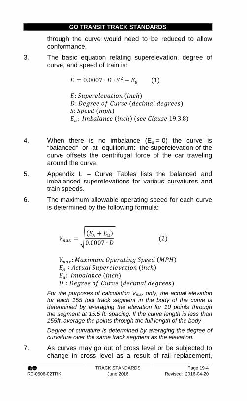
GO TRANSIT TRACK STANDARDS
TRACK STANDARDS Page 19-4 RC-0506-02TRK June 2016 Revised: 2016-04-20
through the curve would need to be reduced to allow conformance.
3. The basic equation relating superelevation, degree of curve, and speed of train is:
𝐸𝐸 = 0.0007 ∙ 𝐷𝐷 ∙ 𝑆𝑆2 − 𝐸𝐸𝑢𝑢 (1) 𝐸𝐸: 𝑆𝑆𝑐𝑐𝑠𝑠𝑑𝑑𝑑𝑑𝑑𝑑𝑙𝑙𝑑𝑑𝑐𝑐𝑠𝑠𝐿𝐿𝑠𝑠𝑜𝑜𝐿𝐿 (𝑠𝑠𝐿𝐿𝑐𝑐ℎ) 𝐷𝐷: 𝐷𝐷𝑑𝑑𝑑𝑑𝑑𝑑𝑑𝑑𝑑𝑑 𝑜𝑜𝑜𝑜 𝑇𝑇𝑐𝑐𝑑𝑑𝑐𝑐𝑑𝑑 (𝑑𝑑𝑑𝑑𝑐𝑐𝑠𝑠𝑑𝑑𝑠𝑠𝑙𝑙 𝑑𝑑𝑑𝑑𝑑𝑑𝑑𝑑𝑑𝑑𝑑𝑑𝑠𝑠) 𝑆𝑆: 𝑆𝑆𝑠𝑠𝑑𝑑𝑑𝑑𝑑𝑑 (𝑑𝑑𝑠𝑠ℎ) 𝐸𝐸𝑢𝑢: 𝐼𝐼𝑑𝑑𝐼𝐼𝑠𝑠𝑙𝑙𝑠𝑠𝐿𝐿𝑐𝑐𝑑𝑑 (𝑠𝑠𝐿𝐿𝑐𝑐ℎ) (𝑠𝑠𝑑𝑑𝑑𝑑 𝑇𝑇𝑙𝑙𝑠𝑠𝑐𝑐𝑠𝑠𝑑𝑑 19.3.8)
4. When there is no imbalance (Eu = 0) the curve is
“balanced“ or at equilibrium: the superelevation of the curve offsets the centrifugal force of the car traveling around the curve.
5. Appendix L – Curve Tables lists the balanced and imbalanced superelevations for various curvatures and train speeds.
6. The maximum allowable operating speed for each curve is determined by the following formula:
𝑉𝑉𝑚𝑚𝑚𝑚𝑚𝑚 = � (𝐸𝐸𝐴𝐴 + 𝐸𝐸𝑢𝑢)0.0007 ∙ 𝐷𝐷
(2)
𝑉𝑉𝑚𝑚𝑚𝑚𝑚𝑚:𝑀𝑀𝑠𝑠𝑒𝑒𝑠𝑠𝑑𝑑𝑐𝑐𝑑𝑑 𝑂𝑂𝑠𝑠𝑑𝑑𝑑𝑑𝑠𝑠𝐿𝐿𝑠𝑠𝐿𝐿𝑑𝑑 𝑆𝑆𝑠𝑠𝑑𝑑𝑑𝑑𝑑𝑑 (𝑀𝑀𝑀𝑀𝑀𝑀) 𝐸𝐸𝐴𝐴 ∶ 𝑇𝑇𝑐𝑐𝐿𝐿𝑐𝑐𝑠𝑠𝑙𝑙 𝑆𝑆𝑐𝑐𝑠𝑠𝑑𝑑𝑑𝑑𝑑𝑑𝑙𝑙𝑑𝑑𝑐𝑐𝑠𝑠𝐿𝐿𝑠𝑠𝑜𝑜𝐿𝐿 (𝑠𝑠𝐿𝐿𝑐𝑐ℎ) 𝐸𝐸𝑢𝑢: 𝐼𝐼𝑑𝑑𝐼𝐼𝑠𝑠𝑙𝑙𝑠𝑠𝐿𝐿𝑐𝑐𝑑𝑑 (𝑠𝑠𝐿𝐿𝑐𝑐ℎ) 𝐷𝐷 ∶ 𝐷𝐷𝑑𝑑𝑑𝑑𝑑𝑑𝑑𝑑𝑑𝑑 𝑜𝑜𝑜𝑜 𝑇𝑇𝑐𝑐𝑑𝑑𝑐𝑐𝑑𝑑 (𝑑𝑑𝑑𝑑𝑐𝑐𝑠𝑠𝑑𝑑𝑠𝑠𝑙𝑙 𝑑𝑑𝑑𝑑𝑑𝑑𝑑𝑑𝑑𝑑𝑑𝑑𝑠𝑠)
For the purposes of calculation Vmax only, the actual elevation for each 155 foot track segment in the body of the curve is determined by averaging the elevation for 10 points through the segment at 15.5 ft. spacing. If the curve length is less than 155ft, average the points through the full length of the body
Degree of curvature is determined by averaging the degree of curvature over the same track segment as the elevation.
7. As curves may go out of cross level or be subjected to change in cross level as a result of rail replacement,
GO TRANSIT TRACK STANDARDS
TRACK STANDARDS Page 19-5 RC-0506-02TRK June 2016 Revised: 2016-04-20
design superelevation shall not exceed 5” (127 mm) without the authority of the Rail Corridors Senior Manager of Track and Structures.
8. The minimum superelevation that can be applied on a curve shall be the greater of: a. ½” (does not apply to balanced superelevation) b. 1” below the balanced elevation for Canadian
Pacific Freight dispatched tracks. c. 2” below the balanced elevation for all other
Freight Timetable Speed; d. 3” below the balanced elevation for Passenger
Timetable Speed (Transport Canada); e. 3” up to a maximum of 4” below the balanced
elevation for GO Trains and UP DMU’s (GO Transit is exempt from the Transport Canada rule in item c);
f. 6” below the balanced elevation for LRC (Light Rapid Commuter) Timetable Speed.
9. The degree of a curve is determined by stretching a 62 ft. (18.9m) cord on the gauge side of the outer rail of the curve. The distance in inches between the centre of this cord and the gauge side of the rail is the degree of the curve.
10. The curve tables give the desired curve elevation for a given curvature and train speed, and alternatively give the maximum train speed for a given curvature and curve elevation. See Appendix L – Curve Tables for balanced and imbalanced superelevations.
11. Rail Operations, Rail Corridors, and the Track Centre of Excellence must be consulted regarding the required zone speeds. a. A zone speed analysis may be required to
determine the proposed Timetable speed. 12. For each type of traffic (passenger, freight, LRC)
determine the balanced superelevation. From there establish the maximum and minimum allowable

GO TRANSIT TRACK STANDARDS
TRACK STANDARDS Page 19-6 RC-0506-02TRK June 2016 Revised: 2016-04-20
superelevation that can be applied based on the traffic speed
13. The maximum elevation for the curve will then be the lesser of the maximum elevations that are calculated, the minimum elevation for the curve will be the greatest of the minimum elevations that are calculated.
14. The elevation for the curve can then be anywhere within this range. The minimum and maximum superelevation calculated above will ensure ride quality and safety for each type of traffic. Selection should therefore be made with consideration to local traffic and conditions using the following guidelines: a. Using a greater superelevation will result in the
weight of slower trains being transferred to the low rail causing damage to the low rail.
b. Using a lesser superelevation will result in faster trains producing greater lateral forces through the curve. This can increase gauge widening and gauge face wear.
15. On main tracks in curves, spirals must be installed between tangents and all curves, and between any two parts of a compound curve if these differ by 1º or more. Spirals provide a transition in both curvature and elevation.
16. Where there are adjacent tracks on a curve, the elevation on the outer track must not be more than the elevation of the inner track unless the distance between track centres is increased to make up for the difference in elevation.
17. On a spiral between a tangent and a curve, the elevation must increase uniformly from the end of a tangent to the beginning of the curve.
18. Similarly, on a spiral between two parts of a compound curve, the elevation must increase uniformly from the end of the flatter curve to the beginning of a sharper curve.
19. The minimum spiral length will be the greater of the two lengths calculated in the equations for Passenger Comfort (3) and Freight Torsion (4):
GO TRANSIT TRACK STANDARDS
TRACK STANDARDS Page 19-7 RC-0506-02TRK June 2016 Revised: 2016-04-20
𝐿𝐿 = 1.63 ∙ 𝐸𝐸𝑢𝑢 ∙ 𝑆𝑆𝑝𝑝 (3) 𝐿𝐿 = 62 ∙ 𝐸𝐸𝐴𝐴 (4) 𝐿𝐿: 𝐿𝐿𝑑𝑑𝐿𝐿𝑑𝑑𝐿𝐿ℎ 𝑜𝑜𝑜𝑜 𝑆𝑆𝑠𝑠𝑠𝑠𝑑𝑑𝑠𝑠𝑙𝑙 (𝑜𝑜𝑑𝑑𝑑𝑑𝐿𝐿) 𝐸𝐸𝑢𝑢:𝑀𝑀𝑠𝑠𝑠𝑠𝑠𝑠𝑑𝑑𝐿𝐿𝑑𝑑𝑑𝑑𝑑𝑑 𝐼𝐼𝑑𝑑𝐼𝐼𝑠𝑠𝑙𝑙𝑠𝑠𝐿𝐿𝑐𝑐𝑑𝑑 (𝑠𝑠𝐿𝐿𝑐𝑐ℎ) 𝑆𝑆𝑝𝑝:𝑀𝑀𝑠𝑠𝑒𝑒𝑠𝑠𝑑𝑑𝑐𝑐𝑑𝑑 𝑀𝑀𝑠𝑠𝑠𝑠𝑠𝑠𝑑𝑑𝐿𝐿𝑑𝑑𝑑𝑑𝑑𝑑 𝑆𝑆𝑠𝑠𝑑𝑑𝑑𝑑𝑑𝑑 (𝑀𝑀𝑀𝑀𝑀𝑀) 𝐸𝐸𝐴𝐴 ∶ 𝑇𝑇𝑐𝑐𝐿𝐿𝑐𝑐𝑠𝑠𝑙𝑙 𝑆𝑆𝑐𝑐𝑠𝑠𝑑𝑑𝑑𝑑𝑑𝑑𝑙𝑙𝑑𝑑𝑐𝑐𝑠𝑠𝐿𝐿𝑠𝑠𝑜𝑜𝐿𝐿 (𝑠𝑠𝐿𝐿𝑐𝑐ℎ)
20. The Passenger Comfort Equation (Equation 3) is used to
ensure that the ride quality around the curve is appropriate for the speed of the passenger train and for the superelevation applied. In certain conditions, such as near open deck bridges or between reverse curves, the required length of spiral may not be available. If the spiral length for passenger comfort cannot be obtained this length of the spiral may be reduced by an amount not exceeding 25% at the discretion of the Rail Corridors Senior Manager of Track and Structures and must be approved in writing.
21. The Freight Torsion equation (Equation 4) ensures cars can physically negotiate the curve. The equation is designed so that the superelevation is never run off at a rate greater than 1 inch (25mm) in 62 feet (18.9m). For safety reasons, this condition must always be met. At certain locations, such as near open deck bridges or between reverse curves, the required length of spiral may not be available. In order to maintain the appropriate runoff rate, the superelevation would then need to run out on to the tangent. This is only allowable under the following conditions: a. The rate of change of superelevation does not
exceed 1 inch in 62 feet. e.g. the superelevation is run out for at least the length given by the Freight Torsion Equation (Equation 4).
b. At least 75% of the superelevation is run out on the spiral.
c. The maximum permissible speed of passenger trains on the curve is 60 m.p.h. or less.

GO TRANSIT TRACK STANDARDS
TRACK STANDARDS Page 19-8 RC-0506-02TRK June 2016 Revised: 2016-04-20
d. The requirements for Passenger Comfort are still met: the length of spiral is not less than 75% of that required for Passenger Comfort (Equation 3).
22. Reverse curves shall be separated by a tangent of at least 100 ft. (30.5 m) in length unless otherwise authorized by the Rail Corridors Senior Manager of Track and Structures in writing.
23. The length of spiral between parts of a compound curve shall be determined by equation 4, where EA will be modified to be the difference between the superelevations on the different parts of the curve.
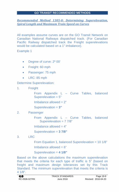
GO TRANSIT RECOMMENDED METHODS
TRACK STANDARDS Page 19-9 RC-0506-02TRK June 2016 Revised: 2016-04-20
Recommended Method 1305-0: Determining Superelevation, Spiral Length and Maximum Train Speed on Curves
All examples assume curves are on the GO Transit Network on Canadian National Railways dispatched track. (For Canadian Pacific Railway dispatched track the Freight superelevations would be calculated based on a 1” imbalance). Example 1
• Degree of curve: 2º 00’
• Freight: 60 mph
• Passenger: 75 mph
• LRC: 85 mph Determine Superelevation: 1. Freight
From Appendix L – Curve Tables, balanced Superelevation = 5” Imbalance allowed = 2” Superelevation = 3”
2. Passenger From Appendix L – Curve Tables, balanced
Superelevation = 7 7/8” Imbalance allowed = 4” Superelevation = 3 7/8”
3. LRC From Equation 1, balanced Superelevation = 10 1/8” Imbalance allowed = 6” Superelevation = 4 1/8”
Based on the above calculations the maximum superelevation that meets the criteria for each type of traffic is 5” (based on freight and maximum design tolerances set by this Track Standard. The minimum superelevation that meets the criteria is 4 1/8”.

GO TRANSIT RECOMMENDED METHODS
TRACK STANDARDS Page 19-10 RC-0506-02TRK June 2016 Revised: 2016-04-20
Apply the minimum Superelevation Superelevation = 4 1/8” Check Vmax:
Using Equation 2: Vmax2= 66 MPH Vmax4= 76 MPH Vmax6= 85 MPH
The allowable speeds are good for each type of traffic. Determine Length of Spiral:
From Passenger Comfort (Equation 3) 𝐿𝐿 = 1.63 ∙ 𝐸𝐸𝑢𝑢 ∙ 𝑆𝑆𝑝𝑝
Eu= 7 7/8” – 4 1/8” = 3 ¾” Sp = 75 MPH L = 458 ft.
From Freight Torsion (Equation 4)
𝐿𝐿 = 62 ∙ 𝐸𝐸𝐴𝐴 L = 256 ft.
The minimum Spiral shall be the greater of the 2. Spiral Length = 458 ft. Example 2
• Degree of curve: 5º 00’
• Freight: 40 mph
• Passenger: 45 mph Determine Superelevation: 1. Freight

GO TRANSIT RECOMMENDED METHODS
TRACK STANDARDS Page 19-11 RC-0506-02TRK June 2016 Revised: 2016-04-20
From Appendix L – Curve Tables, balanced Superelevation = 5 5/8” Imbalance allowed = 2” Superelevation = 3 5/8”
2. Passenger From Appendix L – Curve Tables, balanced
Superelevation = 7 1/8” Imbalance allowed = 4” Superelevation = 3 1/8”
Based on the above calculations the maximum superelevation that meets the criteria for each type of traffic is 5” (based on freight and maximum design tolerances set by this Track Standard. The minimum superelevation that meets the criteria is 3 5/8”. Apply the minimum Superelevation Superelevation = 3 5/8” Check Vmax:
Using Equation 2: Vmax2= 40 MPH Vmax4= 46 MPH
The allowable speeds are good for each type of traffic. Determine Length of Spiral:
From Passenger Comfort (Equation 3) 𝐿𝐿 = 1.63 ∙ 𝐸𝐸𝑢𝑢 ∙ 𝑆𝑆𝑝𝑝
Eu= 7 1/8” – 3 5/8” = 3 ½” Sp = 45 MPH L = 257 ft.
From Freight Torsion (Equation 4)
𝐿𝐿 = 62 ∙ 𝐸𝐸𝐴𝐴

GO TRANSIT RECOMMENDED METHODS
TRACK STANDARDS Page 19-12 RC-0506-02TRK June 2016 Revised: 2016-04-20
L = 225 ft. The minimum Spiral shall be the greater of the 2. Spiral Length = 257 ft. Example 3
• Degree of curve: 6º 00’
• Existing Superelevation : 4 ¾”
• No Freight
• What is Max Passenger? Allowable Passenger imbalance = 4” Balanced Superelevation = 8 ¾” Vmax = 45 MPH S = 45 MPH Max Speed Passenger Speed = 45 MPH Example 4
• Degree of curve: 3º 30’
• Freight: 50 MPH
• Passenger: 55 MPH
• Max Spiral Length = 220 ft. (bridge restrictions) Determine Superelevation: 1. Freight
From Appendix L – Curve Tables, balanced Superelevation = 6 1/8” Imbalance allowed = 2”
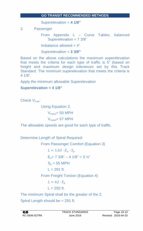
GO TRANSIT RECOMMENDED METHODS
TRACK STANDARDS Page 19-13 RC-0506-02TRK June 2016 Revised: 2016-04-20
Superelevation = 4 1/8”
2. Passenger From Appendix L – Curve Tables, balanced
Superelevation = 7 3/8” Imbalance allowed = 4” Superelevation = 3 3/8”
Based on the above calculations the maximum superelevation that meets the criteria for each type of traffic is 5” (based on freight and maximum design tolerances set by this Track Standard. The minimum superelevation that meets the criteria is 4 1/8”. Apply the minimum allowable Superelevation Superelevation = 4 1/8” Check Vmax:
Using Equation 2: Vmax2= 50 MPH Vmax4= 57 MPH
The allowable speeds are good for each type of traffic. Determine Length of Spiral Required:
From Passenger Comfort (Equation 3) 𝐿𝐿 = 1.63 ∙ 𝐸𝐸𝑢𝑢 ∙ 𝑆𝑆𝑝𝑝
Eu= 7 3/8” – 4 1/8” = 3 ¼” Sp = 55 MPH L = 291 ft.
From Freight Torsion (Equation 4) 𝐿𝐿 = 62 ∙ 𝐸𝐸𝐴𝐴
L = 255 ft. The minimum Spiral shall be the greater of the 2. Spiral Length should be = 291 ft.

GO TRANSIT RECOMMENDED METHODS
TRACK STANDARDS Page 19-14 RC-0506-02TRK June 2016 Revised: 2016-04-20
The spiral length required by the passenger comfort formula exceeds the spiral available. Permission can be obtained from the Rail Corridors Senior Manager of Track and Structures to reduce the required spiral length by 25%. This would reduce the length of spiral to 218 ft.
291 𝑜𝑜𝐿𝐿. ∙ 0.75 = 218.25 𝑜𝑜𝐿𝐿. This falls beneath the physical limitation of 220 ft. The spiral length of 220 ft. can be used provide the superelevation is runoff appropriately. By the freight torsion formula, the superelevation must be runoff over at least 255 ft. Since the Passenger speed is below 60mph, up to 25% percent of the superelevation can be runoff on the tangent.
255 𝑜𝑜𝐿𝐿. ∙ 0.25 = 63.75 𝑜𝑜𝐿𝐿.
255 𝑜𝑜𝐿𝐿. ∙ 0.75 = 191.25 𝑜𝑜𝐿𝐿. 220 𝑓𝑓𝑓𝑓.255 𝑓𝑓𝑓𝑓.
= 86%
The length of spiral track falls beneath the physical limitations of the 220 ft. Therefore, using a spiral length of 220 ft., 86% of the require superelevation (2 7/8 in.) will be run out in the spiral. The other 14% (1/2 in.) will be run out on the tangent.

GO TRANSIT TRACK STANDARDS
TRACK STANDARDS Page 20-1 RC-0506-02TRK June 2016 Revised: 2016-04-20
Section 20 - Bridges and Structures
20.1. Guard Rails
1. Guard rails must be installed at the following locations: a. All bridges that have supporting structure
extending above the top of the ties; b. All bridges that have the underside supporting
structure protruding beyond the deck of the bridge;
c. All bridges that cross major roadways (two lane paved highway or greater);
d. All bridges that cross commercially navigable waterways;
e. All bridges longer than 100 ft. (30.5m); f. All bridges with curves 2º and over; g. All tunnels, snow sheds, and rock sheds with
timber lining, exposed arch ribs, or other lining or construction that is vulnerable to damage or dislodgement; guard rails are not required on unlined tunnels and tunnels with smooth concrete lining; and
h. Any other locations designated by the Rail Corridors Senior Manager of Track and Structures.
2. Guard rails should be considered, where piers of overhead structures are within 17 ft. (5.1m) of centreline of track, there are no crash walls, and the track speed is greater than 10 mph.
3. Existing guardrails that are not required per the above criteria, may not be removed without notifying the Rail Corridors Senior Manager of Track and Structures.
4. On bridges with three or more tracks, the centre tracks do not require guardrails.
5. Guard rails shall be installed as per CN Standards Plan TS-1108.
GO TRANSIT TRACK STANDARDS
TRACK STANDARDS Page 20-2 RC-0506-02TRK June 2016 Revised: 2016-04-20
6. Guardrails should be electrically isolated from the running rail in order to maintain broken rail protection. Guardrails and guardrail plates must not contact the tie plates and must be kept clean and free of debris, particularly metal shavings and filings.
7. In some locations, guardrails are incorporated into the signals system. Employees must take every precaution to avoid shorting out track circuits between the guardrail and the running rail when working around these locations.
8. Guard Rails will be spiked with two spikes per rail, without tie plates on every tie.
9. Whenever guardrails are temporarily removed on main track to accommodate track or bridge work a temporary speed restriction of 30 mph, or track speed is required, whichever is more restrictive..
10. The Senior Manager of Track and Structures may authorize exceptions to this Standard provided both of the following conditions are met: a. The guard rails are removed by a gang to
facilitate maintenance work; and b. The gang performing the work does not leave
the site unattended for a period greater than 15 days without replacing the guardrails.
20.2. Restraining Rails
This section is currently under development.
20.3. Drainage
1. The track shall have adequate sub-surface drainage. 2. Drainage design must take into consideration melt water
produced by switch heaters. 3. Generally, there shall be one surface catch basin for
every two switches, with the catch basin located no more than 10 m from the switch points within yards and within the USRC.

GO TRANSIT TRACK STANDARDS
TRACK STANDARDS Page 20-3 RC-0506-02TRK June 2016 Revised: 2016-04-20
4. Drainage infrastructure design must facilitate future maintenance, including but not necessarily limited to: a. Provision of vehicular & pedestrian access to
catch basins; b. Provision of cleanouts at appropriate intervals;
and c. Consideration for adjacent track maintenance
requirements such as undercutting and track tie replacement.
5. Ditches, culverts or any other drainage facility under or immediately adjacent to the roadbed MUST be maintained so as to allow the free flow of water.
6. Culvert installation will be done in accordance with Track Standard Section 20.4 and the direction of the Rail Corridors Manager of Bridges and Structures.
7. General culvert inspection shall be undertaken per Track Standard Section 14.9 and under the direction of the Rail Corridors Manager of the Bridges and Structures.
20.4. Installation of Culverts
1. Culverts should be placed so that the stream will have as straight an entrance and outlet as possible.
2. The flow line grade of the culvert should be only slightly greater than the natural grade of the stream so the culvert will be self-cleaning
3. Place the culvert as close to the bottom of the stream bed as possible. Placing it too low may cause it to partially fill with sediment; placing it too high may cause ponding.
4. When a culvert is placed under a high fill or on a soil base that may settle, the culvert should be cambered (arched slightly upwards). This will help prevent low spots forming in the centre as settlement occurs.
5. The culvert should extend beyond the toe of the slope a sufficient distance to prevent possible erosion and sloughing of the embankment.

GO TRANSIT TRACK STANDARDS
TRACK STANDARDS Page 20-4 RC-0506-02TRK June 2016 Revised: 2016-04-20
6. All culverts should be installed with the area under the haunches well compacted and all voids filled.
7. All culverts should be placed on stable earth or fine granular foundation. Never install them on a bed that contains large rocks.
8. When soft, unstable material is found at the foundation level, it should be excavated below the flow line grade and backfilled to grade with screenings of another comparable crushed stone. In most cases, removing an additional 12” of material will be adequate.
9. Rock encountered in the foundation should be removed at least 12” below the bottom of the culvert pipe and replaced with granular material to cushion the pipe.
10. When placing two (2) or more corrugated steel pipes alongside of each other, there must be space between them. This is to allow room for tamping the backfill and to provide side support.
11. Backfill material should be free from rocks and hard earth clods larger than 3” in size. Well graded granular material containing a small amount of silt or clay is ideal because it makes a dense, stable fill.
12. When backfilling, start by tamping under the haunches, the lower part of the pipe below the widest part. Continue placing backfill equally on both sides of the pipe. Backfill should be placed in layers of approximately 8” to 12”. Compacted layers should extend at least one diameter either side of the culvert.
13. Minimum cover should be as specified on drawing CN Standard Plan R7A-80.2.
14. Tamping can be accomplished by using hand tampers. They should not weigh less than 20 pounds and not have a tamping face larger than 6” x 6”.
15. Where room permits, power tampers or vibrators can be used.
16. When culverts are replaced by jacking a new pipe adjacent to it, the retired culvert will be completely filled with grout.

GO TRANSIT TRACK STANDARDS
TRACK STANDARDS Page 20-5 RC-0506-02TRK June 2016 Revised: 2016-04-20
17. Changes to existing culvert size or type, or the installation of additional culverts will require a hydrology study and will be reported to the Rail Corridors Senior Manager of Track and Structures.
18. Smooth steel pipe will be ½ inch minimum thickness for culverts up to 60 inches in diameter.
19. Larger diameter smooth steel pipes will be of a design as approved by the Rail Corridors Manager of Bridges and Structures.
20. Where feasible, the preferred method of installation is by auger or jacking.
20.5. Trenching and Shoring
1. The minimum requirements for trenching and excavations may be found in Appendix W – Excavation Limits Adjacent a Railway.
2. The maximum height of an excavated vertical face without shoring must not exceed 4.5 ft. (1.4m).
3. Excavations greater than 8 ft. (2.4 m) in depth must be protected by an adequate barrier.
4. A Professional Engineer must design all excavations that: a. Exceed 12 ft. (3.6m) wide and / or more than 12
ft. (3.6m deep); b. Are wet or exhibit signs of water seepage
regardless of height; c. Require excavation shoring systems (e.g. sheet
piling, soldier piles and lagging, and tie back systems, etc.); and
d. Are in close proximity to tracks, a roadway or require blasting operations.
20.6. Clearances
1. Every structure over or beside a railway track, except those structures governed by Clause 20.6.2, 20.6.3,
GO TRANSIT TRACK STANDARDS
TRACK STANDARDS Page 20-6 RC-0506-02TRK June 2016 Revised: 2016-04-20
20.6.4 below, shall afford the minimum clearances set out in Figure 2561;
2. All railway bridges, snow-sheds and overhead timber bridges shall afford the minimum clearances as set out in Figure 26;
3. All railway tunnels shall afford the minimum clearances as set out in Figure 27;
4. Industrial sidings shall afford the minimum clearances as set out in Figure 28, where required to be different to those set out in Figure 25;
5. A lateral allowance for track curvature of 25.4 mm (1 inch) per degree shall be provided;
6. All clearance diagrams shall be perpendicular to the plane of the top of rails.
7. All existing structures, bridges, snow-sheds, overhead timber bridges and tunnels which met previous clearance requirements, but encroach within the clearance limits prescribed herein, shall not be considered as having less than standard clearances and shall be permitted to remain until the restrictive feature is modified or replaced.
8. Clearances not meeting the requirements of this section, are permitted in the following circumstances: a. On a track at a main shop, diesel or car shop; b. Doorways in buildings; c. Ramps, platforms and similar structures to
facilitate loading, unloading, servicing and maintenance;
d. Permanent structures to provide for or support locomotive and car wash facilities;
e. Temporary restrictions necessary to facilitate construction or repair of overhead structures, in which case the train crews are to be notified.
9. Where circumstances do not permit the standard clearances prescribed:

GO TRANSIT TRACK STANDARDS
TRACK STANDARDS Page 20-7 RC-0506-02TRK June 2016 Revised: 2016-04-20
a. Exceptions may be authorized by the Rail Corridors Senior Manager of Track and Structures in writing.
b. Modifications may be made to clearances covered in Clause 20.6.7 and Clause 20.6.8 a, d, and e upon approval of the Rail Corridors Senior Manager of Track and Structures in writing.
c. The construction of a structure creating less than standard clearances shall not begin until approved by the Rail Corridors Senior Manager of Track and Structures in writing.
10. At locations described in Clause 20.6.8 b and c and where the Rail Corridors Senior Manager of Track and Structures has approved a less than standard clearance pursuant to Clauses 20.6.1 and 20.6.9, a restricted clearance sign, shall be erected and maintained adjacent to the track on which the restriction is located and at an adequate distance from the restriction. Where physical impediments preclude the erection of such a sign, the less than standard clearance will be identified in special instructions.
11. Requests for approval of less than standard clearances shall be submitted to the Rail Corridors Senior Manager of Track and Structures and shall include the following information: a. Reasons for less than standard clearance; b. If operations over the track concerned will be by
locomotive, car puller or gravity; c. If locomotives will pass the point of less than
standard clearance; d. Type of cars that will pass the point of less than
standard clearance; e. Confirmation that track cannot be realigned to
avoid the less than standard clearance or that the restricting object cannot be placed where it would no longer represent a restriction;
f. If the less than standard clearance will be permanent or temporary;

GO TRANSIT TRACK STANDARDS
TRACK STANDARDS Page 20-8 RC-0506-02TRK June 2016 Revised: 2016-04-20
g. A drawing showing the relative position of the track and the obstruction, with cross sections at each point of less than standard clearance indicating the vertical clearance from the top of rail and the horizontal clearance from the centre line of the track, together with the location of the restricted clearance sign.
h. Employees must not ride the side or above the roof of a moving engine or car when passing side and/or overhead restrictions.
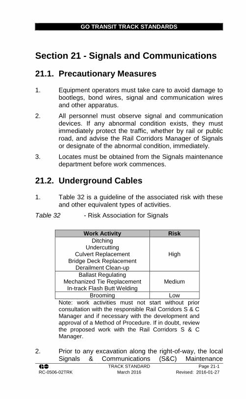
GO TRANSIT TRACK STANDARDS
TRACK STANDARD Page 21-1 RC-0506-02TRK March 2016 Revised: 2016-01-27
Section 21 - Signals and Communications
21.1. Precautionary Measures
1. Equipment operators must take care to avoid damage to bootlegs, bond wires, signal and communication wires and other apparatus.
2. All personnel must observe signal and communication devices. If any abnormal condition exists, they must immediately protect the traffic, whether by rail or public road, and advise the Rail Corridors Manager of Signals or designate of the abnormal condition, immediately.
3. Locates must be obtained from the Signals maintenance department before work commences.
21.2. Underground Cables
1. Table 32 is a guideline of the associated risk with these and other equivalent types of activities.
Table 32 - Risk Association for Signals
Work Activity Risk Ditching
Undercutting Culvert Replacement
Bridge Deck Replacement Derailment Clean-up
High
Ballast Regulating Mechanized Tie Replacement
In-track Flash Butt Welding Medium
Brooming Low Note: work activities must not start without prior consultation with the responsible Rail Corridors S & C Manager and if necessary with the development and approval of a Method of Procedure. If in doubt, review the proposed work with the Rail Corridors S & C Manager.
2. Prior to any excavation along the right-of-way, the local Signals & Communications (S&C) Maintenance

GO TRANSIT TRACK STANDARDS
TRACK STANDARD Page 21-2 RC-0506-02TRK March 2016 Revised: 2016-01-27
Superintendent must be notified a minimum of 7 days in advance of work, except in case of emergencies. a. Where it is reasonably practical, the qualified S
& C employee shall remain at the excavation site while the work is being performed.
b. Permanent cable markers are installed only to indicate the presence of buried cable and are not meant to indicate the precise location of the cable. Cables should be day-lighted to obtain exact location and depth.
c. Cables may run anywhere on the right-of-way, and at varying depths. Shallow cables may be encountered, especially near culverts, station platforms, underground passageways, and the ends of ducts at approaches to bridges and tunnels.
d. Buried signal and communication plant may include power distribution circuits energized at potentials as high as 7200 volts AC. Use extreme care when excavating near such facilities to avoid damage to cable or wire insulation. When necessary to protect persons excavating in proximity to hazardous equipment and cables, power distribution circuits in the affected area must be isolated or de-energized for work safety.
e. When it is necessary to isolate or de-energize 7200 Volt circuits for safety, a power clearance form will be generated by the responsible Utility Maintenance supervisor. No excavation work shall begin until the foreman has confirmed that this clearance form is in effect. When the work is complete, the foreman shall insure that all employees involved in the work area are free and clear from the power distribution circuits, before reporting so to the responsible Utility Maintenance supervisor.
f. Whenever excavating is done, in proximity to buried power distribution cables, it shall be done only by use of a vacuum truck or by hand
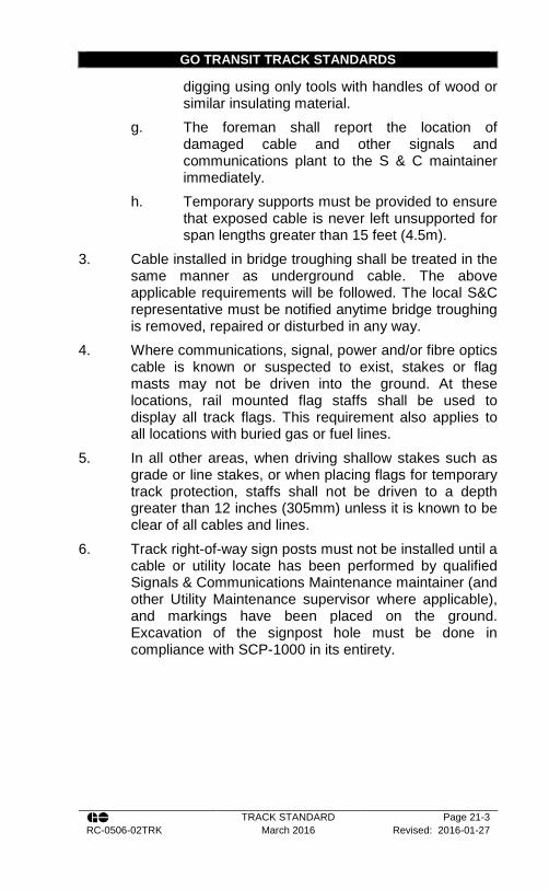
GO TRANSIT TRACK STANDARDS
TRACK STANDARD Page 21-3 RC-0506-02TRK March 2016 Revised: 2016-01-27
digging using only tools with handles of wood or similar insulating material.
g. The foreman shall report the location of damaged cable and other signals and communications plant to the S & C maintainer immediately.
h. Temporary supports must be provided to ensure that exposed cable is never left unsupported for span lengths greater than 15 feet (4.5m).
3. Cable installed in bridge troughing shall be treated in the same manner as underground cable. The above applicable requirements will be followed. The local S&C representative must be notified anytime bridge troughing is removed, repaired or disturbed in any way.
4. Where communications, signal, power and/or fibre optics cable is known or suspected to exist, stakes or flag masts may not be driven into the ground. At these locations, rail mounted flag staffs shall be used to display all track flags. This requirement also applies to all locations with buried gas or fuel lines.
5. In all other areas, when driving shallow stakes such as grade or line stakes, or when placing flags for temporary track protection, staffs shall not be driven to a depth greater than 12 inches (305mm) unless it is known to be clear of all cables and lines.
6. Track right-of-way sign posts must not be installed until a cable or utility locate has been performed by qualified Signals & Communications Maintenance maintainer (and other Utility Maintenance supervisor where applicable), and markings have been placed on the ground. Excavation of the signpost hole must be done in compliance with SCP-1000 in its entirety.


GO TRANSIT TRACK STANDARDS
TRACK STANDARD Page 22-1 RC-0506-02TRK March 2016 Revised: 2016-01-27
Section 22 - Platforms 1. GO station platforms adjacent to tangent track shall be
located laterally and vertically in accordance with the Table 33. (See Metrolinx Design Requirements Manual.)
Table 33 Platform Clearances
Location Gauge Face to Edge of Platform
Vertical Clearance ATR
USRC 1,525mm* (60 1/16”)
203mm (8”)
Mixed Use (Freight) Corridors
1,632mm (64 ¼”)
127mm (5”)
GO Only Corridors 1,632mm (64 ¼”)
254mm (10”)
UP Platforms 1,073mm (42 1/4”)
1,295mm (60”)
* Construction tolerance of -25mm/+0mm 2. Clearance from top of tunnel structure to base of rail
shall be a minimum of 0.457 m, (1’-6”). 3. Tunnel shall have a minimum slope of 0.30% for
drainage. 4. Pedestrian tunnels shall be designed for railway loading,
minimum Cooper E80 plus diesel impact. 5. At a minimum utilities parallel to the track must be
located laterally so as not to be within the Zone of Influence of the track. The Zone of Influence is defined as a line extending from the bottom of end of track tie at a slope of 1:2, subject to geotechnical review.
6. At a minimum, utility structures such as duct banks, pull boxes, maintenance holes, catch basins, etc., must be no higher than the bottom of track tie.
7. During snow clearing operations on station platforms or other GO / Metrolinx owned facilities, snow shall NOT be plowed, shovelled, or by any other means, dumped onto the track, ballast, signals, or other railway infrastructure. This includes within the USRC.


GO TRANSIT TRACK STANDARDS
TRACK STANDARDS Page 1 RC-0506-02TRK JUNE 2016 Revised: 2016-04-20
APPENDIX A – TRACK INSPECTION FREQUENCIES
Table 34 Routine Track Inspection Frequencies
Routine Track Inspection Frequency
Type of Track
Class of Track
Annual Tonnage
< 5 MGT 5-15 MGT >15MGT
All Main Track
1 Weekly Weekly Weekly
2, 3 Twice Weekly
Twice Weekly
Twice Weekly
4, 5 Twice Weekly
Twice Weekly
Twice Weekly
Yard Tracks
1 Weekly Weekly Weekly Unclassified Monthly Monthly Monthly
Inactive Track Before being used
Table 35 Walking Track Inspection Frequencies
Walking Track Inspection Frequency
Class of Track
Annual Tonnage
<5 MGT 5 - 15 MGT
>15 – 30 MGT > 30 MGT
1 N/A N/A N/A N/A 2 Annually Annually Annually Annually 3 Annually Annually Annually Annually
4,5 Annually Annually Annually Annually

GO TRANSIT TRACK STANDARDS
TRACK STANDARDS Page 2 RC-0506-02TRK JUNE 2016 Revised: 2016-04-20
Table 36 Joint Bar Inspection Frequencies
Joint Bar Inspection Frequency Minimum Number of Inspections Per Calendar Year1
Class of Track
Passenger (MGT) Freight (MGT)
<20 ≥20 <40 ≥40 and <60
≥60
5+ 32 42 2 32 42
4 2 32 2 32 42 3 2 2 1 2 2 2 1 1 0 0 0 1 0 0 0 0 0
Excepted Track N/A N/A 0 0 0
1 Where GO Transit operates both freight and passenger trains over a given segment of track, and there are two different possible inspection interval requirements, the more frequent inspection interval applies. 2 When extreme weather conditions prevent an inspection of a particular territory within the required interval, the Rail Corridors Senior Manager of Track and Structures may extend the interval by up to 30 calendar days from the last day that the extreme weather condition prevented the required inspection.
Table 37 Derail Inspection Frequency
Inspection Frequency for Derails
Type of Inspection Description
Walking Inspection Each derail shall be inspected on foot at least monthly,
observing overall condition.
Detailed Inspection A thorough detailed observation of each derail shall be performed
annually. Particular attention should be paid to tie,
spike/screw, and ballast condition. Check for any
distortion, fractures, damage from derailments or accidents or
unusual wear on the derail.
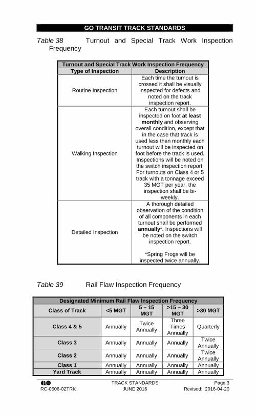
GO TRANSIT TRACK STANDARDS
TRACK STANDARDS Page 3 RC-0506-02TRK JUNE 2016 Revised: 2016-04-20
Table 38 Turnout and Special Track Work Inspection Frequency
Turnout and Special Track Work Inspection Frequency Type of Inspection Description
Routine Inspection
Each time the turnout is crossed it shall be visually inspected for defects and
noted on the track inspection report.
Walking Inspection
Each turnout shall be inspected on foot at least monthly and observing
overall condition, except that in the case that track is
used less than monthly each turnout will be inspected on foot before the track is used. Inspections will be noted on the switch inspection report. For turnouts on Class 4 or 5 track with a tonnage exceed
35 MGT per year, the inspection shall be bi-
weekly.
Detailed Inspection
A thorough detailed observation of the condition of all components in each turnout shall be performed annually*. Inspections will
be noted on the switch inspection report.
*Spring Frogs will be
inspected twice annually.
Table 39 Rail Flaw Inspection Frequency
Designated Minimum Rail Flaw Inspection Frequency
Class of Track <5 MGT 5 – 15 MGT
>15 – 30 MGT >30 MGT
Class 4 & 5 Annually Twice Annually
Three Times
Annually Quarterly
Class 3 Annually Annually Annually Twice Annually
Class 2 Annually Annually Annually Twice Annually
Class 1 Annually Annually Annually Annually Yard Track Annually Annually Annually Annually

GO TRANSIT TRACK STANDARDS
TRACK STANDARDS Page 4 RC-0506-02TRK JUNE 2016 Revised: 2016-04-20
Table 40 Electronic Geometry Inspection Frequency
Designated Minimum Electronic Geometry Inspection Frequency
Class of Track <5 MGT 5 – 15 MGT
>15 – 30 MGT >30 MGT
Class 5 HGIV – Twice
Annually
HGIV - Twice
Annually
HGIV - Twice
Annually
HGIV - Three Times
Annually
Class 4 HGIV - Twice
Annually
HGIV - Twice
Annually
HGIV - Twice
Annually
HGIV - Twice
Annually
Class 3 HGIV – Twice
Annually
HGIV – Twice
Annually
HGIV - Twice
Annually
HGIV - Twice
Annually
Class 2 HGIV – Twice
Annually
HGIV – Twice
Annually
HGIV – Twice
Annually
HGIV – Twice
Annually
Class 1 LGIV - Annually
HGIV – Annually
HGIV – Annually
HGIV – Annually
Crossovers HGIV – Twice
Annually
HGIV – Twice
Annually
HGIV – Twice
Annually
HGIV – Twice
Annually
Yard Tracks LGIV - Annually
LGIV - Annually
LGIV - Annually
LGIV - Annually

GO TRANSIT TRACK STANDARDS
TRACK STANDARDS Page 5 RC-0506-02TRK JUNE 2016 Revised: 2016-04-20
APPENDIX B – PRIORITY DEFECTS Tr
ack
Cla
ss
5 95*
80
57-1
/4”
(145
4)
3/8”
(9
)
1/2”
(1
2)
3/8”
(9
)
3/4”
(1
9)
5/8”
(1
6)
* 10
0 m
ph fo
r LR
C T
rain
s
4 80
60
57-1
/4”
(145
4)
1-1/
8”
(28)
1-1/
/8”
(28)
3/4”
(1
9)
1”
(25)
15/1
6”
(24)
3 60
40
57-1
/4”
(145
4)
1-3/
8”
(35)
1-3/
8”
(35)
7/8”
(2
2)
1-1/
4”
(32)
1-1/
8”
(28)
2 30
25
57-1
/4”
(145
4)
2-1/
4”
(57)
2-1/
4”
(57)
No
Lim
it
1-1/
2”
(38)
1-5/
8”
(41)
1 15
10
57-1
/2”
(146
0)
3-3/
4”
(95)
3-3/
4”
(95)
No
Lim
it
2”
(51)
1-7/
8”
(48)
PRIO
RIT
Y D
EFEC
TS
Pass
enge
r Fr
eigh
t +
The
dist
ance
bet
wee
n th
e ga
uge
poin
ts o
f the
rails
5/8
” be
low
the
top
of o
f the
rail
may
not
be
mor
e th
an
The
devi
atio
n of
the
mid
-offs
et fr
om a
62
ft. (1
8.9m
) lin
e m
ay n
ot b
e m
ore
than
The
devi
atio
n of
the
mid
-ord
inat
e fr
om a
62
ft. (1
8.9m
) ch
ord
may
not
be
mor
e th
an
The
devi
atio
n of
the
mid
-ord
inat
e fr
om a
31
ft. (9
.45m
) ch
ord
may
not
be
mor
e th
an
The
devi
atio
n fro
m u
nifo
rm p
rofil
e on
eith
er ra
il at
the
mid
-ord
inat
e o
f an
62 ft
. (18
.9m
) cho
rd m
ay n
ot b
e m
ore
than
D
iffer
ence
in c
ross
leve
l bet
wee
n an
y tw
o po
ints
31
ft.
(9.4
5m) a
part
in s
pira
l may
not
be
mor
e th
an
Spee
d (m
ph)
Wid
e G
auge
Alig
nmen
t Ta
ngen
t 62f
t (1
8.9m
) A
lignm
ent
Cur
ve 6
2ft
(18.
9m)
Alig
nmen
t C
urve
31f
t (9
.45m
)
Sur
face
War
p 31
ft (9
.45m
)
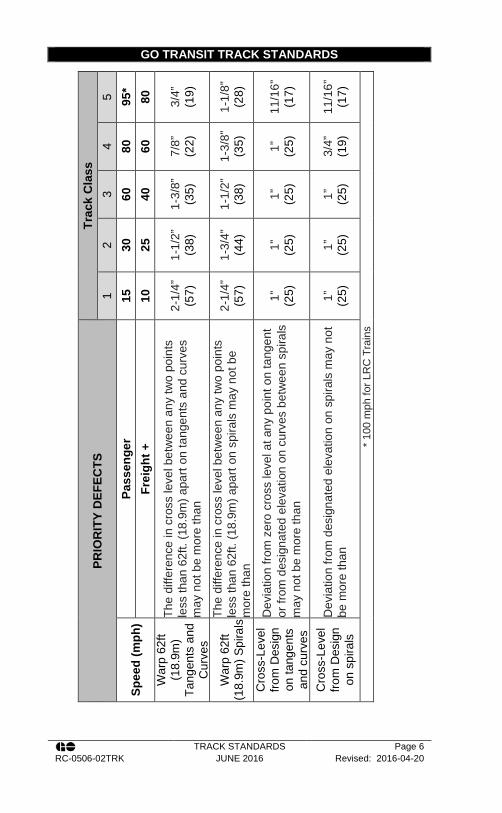
GO TRANSIT TRACK STANDARDS
TRACK STANDARDS Page 6 RC-0506-02TRK JUNE 2016 Revised: 2016-04-20
Trac
k C
lass
5 95
* 80
3/4”
(1
9)
1-1/
8”
(28)
11/1
6”
(17)
11/1
6”
(17)
* 10
0 m
ph fo
r LR
C T
rain
s
4 80
60
7/8”
(2
2)
1-3/
8”
(35)
1”
(25)
3/4”
(1
9)
3 60
40
1-3/
8”
(35)
1-1/
2”
(38)
1”
(25)
1”
(25)
2 30
25
1-1/
2”
(38)
1-3/
4”
(44)
1”
(25)
1”
(25)
1 15
10
2-1/
4”
(57)
2-1/
4”
(57)
1”
(25)
1”
(25)
PRIO
RIT
Y D
EFEC
TS
Pass
enge
r Fr
eigh
t +
The
diffe
renc
e in
cro
ss le
vel b
etw
een
any
two
poin
ts
less
than
62f
t. (1
8.9m
) apa
rt on
tang
ents
and
cur
ves
may
not
be
mor
e th
an
The
diffe
renc
e in
cro
ss le
vel b
etw
een
any
two
poin
ts
less
than
62f
t. (1
8.9m
) apa
rt on
spi
rals
may
not
be
mor
e th
an
Dev
iatio
n fro
m z
ero
cros
s le
vel a
t any
poi
nt o
n ta
ngen
t or
from
des
igna
ted
elev
atio
n on
cur
ves
betw
een
spira
ls
may
not
be
mor
e th
an
Dev
iatio
n fro
m d
esig
nate
d el
evat
ion
on s
pira
ls m
ay n
ot
be m
ore
than
Spee
d (m
ph)
War
p 62
ft (1
8.9m
) Ta
ngen
ts a
nd
Cur
ves
War
p 62
ft (1
8.9m
) Spi
rals
Cro
ss-L
evel
fro
m D
esig
n
on ta
ngen
ts
and
curv
es
Cro
ss-L
evel
fro
m D
esig
n
on s
pira
ls

GO TRANSIT TRACK STANDARDS
TRACK STANDARDS Page 7 RC-0506-02TRK JUNE 2016 Revised: 2016-04-20
APPENDIX C – URGENT DEFECTS Tr
ack
Cla
ss
5 95*
80
57-1
/2”
(146
0)
3/4”
(1
9)
5/8”
(1
6)
1/2”
(1
2)
1-1/
4”
(31.
75)
1”
(25)
*
100
mph
for L
RC
Tra
ins
4 80
60
57-1
/2”
(146
0)
1-1/
2”
(38)
1-1/
2”
(38)
1”
(25)
2”
(51)
1-1/
2”
(38)
3 60
40
57-3
/4”
(146
6)
1-3/
4”
(44)
1-3/
4”
(44)
1-1/
4”
(31)
2-1/
4”
(57)
2”
(51)
2 30
25
57-3
/4”
(146
6)
3”
(76)
3”
(76)
No
Lim
it
2-3/
4”
(70)
3”
(76)
1 15
10
57-3
/4”
(146
6)
5”
(127
)
5”
(127
)
No
Lim
it
3”
(76)
3-1/
2”
(89)
UR
GEN
T D
EFEC
TS
Pass
enge
r Fr
eigh
t +
The
dist
ance
bet
wee
n th
e ga
uge
poin
ts o
f th
e ra
ils
5/8”
(16
mm
) be
low
the
top
0f
of t
he r
ail m
ay n
ot b
e m
ore
than
The
devi
atio
n of
the
mid
-offs
et f
rom
a 6
2 ft.
(18
.9m
) lin
e m
ay n
ot b
e m
ore
than
The
devi
atio
n of
the
mid
-ord
inat
e f
rom
a 6
2 ft.
(1
8.9m
) cho
rd m
ay n
ot b
e m
ore
than
The
devi
atio
n of
the
mid
-ord
inat
e f
rom
a 3
1 ft.
(9
.45m
) cho
rd m
ay n
ot b
e m
ore
than
The
devi
atio
n fro
m u
nifo
rm p
rofil
e on
eith
er ra
il at
the
mid
-ord
inat
e o
f an
62
ft. (
18.9
m)
chor
d m
ay n
ot b
e m
ore
than
Th
e ru
noff
in a
ny 3
1ft
(9.4
5m)
at t
he e
nd o
f a
rais
e m
ay n
ot b
e m
ore
than
Spee
d (m
ph)
Wid
e G
auge
Alig
nmen
t Ta
ngen
t 62f
t (1
8.9m
)
Alig
nmen
t C
urve
62f
t (1
8.9m
)
Alig
nmen
t C
urve
31f
t (9
.45m
)
Sur
face
Run
off a
t End
of
a R
aise

GO TRANSIT TRACK STANDARDS
TRACK STANDARDS Page 8 RC-0506-02TRK JUNE 2016 Revised: 2016-04-20
Trac
k C
lass
5 95
* 80
3/4”
(1
9)
1-1/
2”
(38)
1”
(25)
1-1/
2”
(38)
1”
(25)
* 10
0 m
ph fo
r LR
C T
rain
s
4 80
60
1”
(25)
1-3/
4”
(44)
1-1/
4”
(31)
1-3/
4”
(44)
1-1/
4”
(31)
3 60
40
1-1/
4”
(31)
2”
(51)
1-3/
4”
(44)
2”
(51)
1-3/
4”
(44)
2 30
25
1-3/
4”
(44)
2-1/
4”
(57)
2”
(51)
2-1/
4”
(57)
2”
(51)
1 15
10
2”
(51)
3”
(76)
3”
(76)
3”
(76)
3”
(76)
UR
GEN
T D
EFEC
TS
Pass
enge
r Fr
eigh
t +
The
diffe
renc
e in
cro
ss le
vel b
etw
een
any
two
poin
ts
less
tha
n 62
ft (1
8.9m
) ap
art
on t
ange
nts
and
curv
es
may
not
be
mor
e th
an
The
diffe
renc
e in
cro
ss le
vel b
etw
een
any
two
poin
ts
less
tha
n 62
ft (1
8.9m
) ap
art
on t
ange
nts
and
curv
es
may
not
be
mor
e th
an
The
diffe
renc
e in
cro
ss le
vel b
etw
een
any
two
poin
ts
less
tha
n 62
ft (1
8.9m
) ap
art
on s
pira
ls m
ay n
ot b
e m
ore
than
Dev
iatio
n fro
m
zero
cr
oss
leve
l at
an
y po
int
on
tang
ent
or
from
de
sign
ated
el
evat
ion
on
curv
es
betw
een
spira
ls m
ay
not b
e m
ore
than
Dev
iatio
n fro
m d
esig
nate
d el
evat
ion
on s
pira
ls m
ay
not b
e m
ore
than
Spee
d (m
ph)
War
p 31
ft (9
.45m
)
War
p 62
ft (1
8.9m
) Ta
ngen
ts a
nd
Cur
ves
War
p 62
ft (1
8.9m
) Spi
rals
Cro
ss-L
evel
fro
m D
esig
n
on ta
ngen
ts
and
curv
es
Cro
ss-L
evel
fro
m D
esig
n
on s
pira
ls
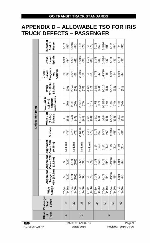
GO TRANSIT TRACK STANDARDS
TRACK STANDARDS Page 9 RC-0506-02TRK JUNE 2016 Revised: 2016-04-20
APPENDIX D – ALLOWABLE TSO FOR IRIS TRUCK DEFECTS – PASSENGER
Def
ect i
nch
(mm
)
Run
off a
t En
d of
R
aise
3-1/
2 (8
9)
3-5/
16
(84)
3-
1/8
(79)
3 (76)
2-
1/2
(63)
2-
5/16
(5
8)
2-1/
8 (5
4)
2 (51)
Cro
ss-
Leve
l Sp
irals
1-3/
4 (4
4)
1-5/
8 (4
1)
1-9/
16
(39)
1-
1/2
(38)
1-
3/8
(35)
1-
5/16
(3
3)
1-1/
4 (3
1)
1-1/
4 (3
1)
Cro
ss-
Leve
l Ta
ngen
ts
and
Cur
ves
3 (76)
2-
5/8
(66)
2-
5/16
(5
8)
2 (51)
1-
7/8
(47)
1-
13/1
6 (4
6)
1-3/
4 (4
4)
1-3/
4 (4
4)
War
p 62
ft(18
.9m
) Spi
rals
3 (76)
2-
3/4
(69)
2-
1/2
(63)
2-
1/4
(57)
2-
1/8
(54)
2-
1/16
(5
2)
2-1/
16
(52)
2 (51)
War
p 62
ft
(18.
9m)
Tang
ents
an
d C
urve
s
3 (76)
2-
5/8
(66)
2-
5/16
(5
9)
2 (51)
1-
7/8
(47)
1-
13/1
6 (4
6)
1-3/
4 (4
4)
1-3/
4 (4
4)
War
p 31
ft (9
.45m
) Sp
irals
2 (51)
1-
7/8
(47)
1-
13/1
6 (4
6)
1-3/
4 (4
4)
1-1/
2 (3
8)
1-3/
8 (3
5)
1-5/
16
(33)
1-
1/4
(31)
Surf
ace
3 (76)
2-
7/8
(73)
2-
13/1
6 (7
1)
2-3/
4 (7
0)
2-1/
2 (6
3)
2-3/
8 (6
0)
2-5/
16
(58)
2-
1/4
(57)
Alig
nmen
t C
urve
31f
t (9
.45m
)
No L
imit
No L
imit
No L
imit
No L
imit
1-1/
4 (3
1)
1-1/
4 (3
1)
1-1/
4 (3
1)
1-1/
4 (3
1)
Alig
nmen
t C
urve
62f
t (1
8.9m
)
5 (1
27)
4-1/
4 (1
08)
3-5/
8 (9
2)
3 (76)
2-
3/8
(60)
2-
1/8
(54)
1-
15/1
6 (4
9)
1-3/
4 (4
4)
Alig
nmen
t Ta
ngen
t 62
ft (1
8.9m
)
5 (1
27)
4-1/
4 (1
08)
3-5/
8 (9
2)
3 (76)
2-
3/8
(60)
2-
1/8
(54)
1-
15/1
6 (4
9)
1-3/
4 (4
4)
Wid
e G
auge
57-3
/4
(146
6)
57-3
/4
(146
6)
57-3
/4
(146
6)
57-3
/4
(146
6)
57-3
/4
(146
6)
57-3
/4
(146
6)
57-3
/4
(146
6)
57-3
/4
(146
6)
Pass
enge
r Tr
ain
Spee
d
15
20
25
30
45
50
55
60
Cla
ss
of
Trac
k
1 2 3
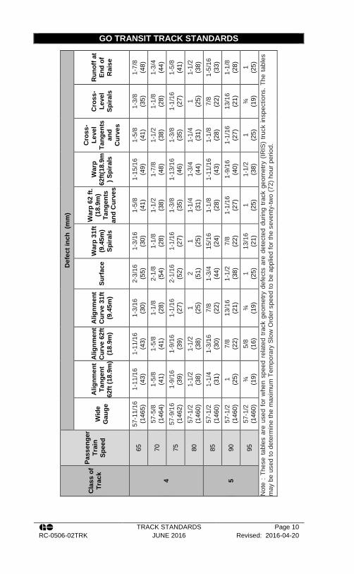
GO TRANSIT TRACK STANDARDS
TRACK STANDARDS Page 10 RC-0506-02TRK JUNE 2016 Revised: 2016-04-20
Def
ect i
nch
(mm
)
Run
off a
t En
d of
R
aise
1-7/
8 (4
8)
1-3/
4 (4
4)
1-5/
8 (4
1)
1-1/
2 (3
8)
1-5/
16
(33)
1-
1/8
(28)
1 (25)
N
ote
: The
se ta
bles
are
use
d fo
r w
hen
spee
d re
late
d tra
ck g
eom
etry
def
ects
are
det
ecte
d du
ring
track
geo
met
ry (
IRIS
) tru
ck in
spec
tions
. The
tabl
es
may
be
used
to d
eter
min
e th
e m
axim
um T
empo
rary
Slo
w O
rder
spe
ed to
be
appl
ied
for t
he s
even
ty-tw
o (7
2) h
our p
erio
d.
Cro
ss-
Leve
l Sp
irals
1-3/
8 (3
5)
1-1/
8 (2
8)
1-1/
16
(27)
1 (25)
7/
8 (2
2)
13/1
6 (2
1)
¾
(19)
Cro
ss-
Leve
l Ta
ngen
ts
and
Cur
ves
1-5/
8 (4
1)
1-1/
2 (3
8)
1-3/
8 (3
5)
1-1/
4 (3
1)
1-1/
8 (2
8)
1-1/
16
(27)
1 (25)
War
p 62
ft(18
.9m
) Spi
rals
1-15
/16
(49)
1-
7/8
(48)
1-
13/1
6 (4
6)
1-3/
4 (4
4)
1-11
/16
(43)
1-
9/16
(4
0)
1-1/
2 (3
8)
War
p 62
ft.
(18.
9m)
Tang
ents
an
d C
urve
s
1-5/
8 (4
1)
1-1/
2 (3
8)
1-3/
8 (3
5)
1-1/
4 (3
1)
1-1/
8 (2
8)
1-1/
16
(27)
1 (25)
War
p 31
ft (9
.45m
) Sp
irals
1-3/
16
(30)
1-
1/8
(28)
1-
1/16
(2
7)
1 (25)
15
/16
(24)
7/
8 (2
2)
13/1
6 (2
1)
Surf
ace
2-3/
16
(55)
2-
1/8
(54)
2-
1/16
(5
2)
2 (51)
1-
3/4
(44)
1-
1/2
(38)
1 (25)
Alig
nmen
t C
urve
31f
t (9
.45m
)
1-3/
16
(30)
1-
1/8
(28)
1-
1/16
(2
7)
1 (25)
7/
8 (2
2)
13/1
6 (2
1)
¾
(19)
Alig
nmen
t C
urve
62f
t (1
8.9m
)
1-11
/16
(43)
1-
5/8
(41)
1-
9/16
(3
9)
1-1/
2 (3
8)
1-3/
16
(30)
7/
8 (2
2)
5/8
(16)
Alig
nmen
t Ta
ngen
t 62
ft (1
8.9m
)
1-11
/16
(43)
1-
5/8
(41)
1-
9/16
(3
9)
1-1/
2 (3
8)
1-1/
4 (3
1)
1 (25)
¾
(1
9)
Wid
e G
auge
57-1
1/16
(1
465)
57
-5/8
(1
464)
57
-9/1
6 (1
462)
57
-1/2
(1
460)
57
-1/2
(1
460)
57
-1/2
(1
460)
57
-1/2
(1
460)
Pass
enge
r Tr
ain
Spee
d
65
70
75
80
85
90
95
Cla
ss o
f Tr
ack
4 5

GO TRANSIT TRACK STANDARDS
TRACK STANDARDS Page 11 RC-0506-02TRK JUNE 2016 Revised: 2016-04-20
APPENDIX E – ALLOWABLE TSO FOR IRIS TRUCK DEFECTS – FREIGHT
Def
ect i
nch
(mm
)
Run
off a
t En
d of
R
aise
3-1/
2 (8
9)
3-5/
16
(84)
3-
1/8
(79)
3 (76)
2-
5/8
(66)
2-
5/16
(5
9)
2 (51)
Cro
ss-
Leve
l Sp
irals
1-3/
4 (4
4)
1-5/
8 (4
1)
1-9/
16
(39)
1-
1/2
(38)
1-
3/8
(35)
1-
5/16
(3
3)
1-1/
4 (3
1)
Cro
ss-
Leve
l Ta
ngen
ts
and
Cur
ves
3 (76)
2-
5/8
(66)
2-
5/16
(5
8)
2 (51)
1-
7/8
(47)
1-
13/1
6 (4
6)
1-3/
4 (4
4)
War
p 62
ft(18
.9m
) Spi
rals
3 (76)
2-
3/4
(69)
2-
1/2
(63)
2-
1/4
(57)
2-
1/8
(54)
2-
1/16
(5
2)
2 (51)
War
p 62
ft
(18.
9m)
Tang
ents
an
d C
urve
s
3 (76)
2-
5/8
(66)
2-
5/16
(5
9)
2 (51)
1-
7/8
(48)
1-
13/1
6 (4
6)
1-3/
4 (4
4)
War
p 31
ft (9
.45m
) Sp
irals
2 (51)
1-
7/8
(47)
1-
13/1
6 (4
6)
1-3/
4 (4
4)
1-9/
16
(40)
1-
3/8
(35)
1-
1/4
(31)
Surf
ace
3 (76)
2-
7/8
(73)
2-
13/1
6 (7
1)
2-3/
4 (7
0)
2-9/
16
(65)
2-
3/8
(60)
2-
1/4
(57)
Alig
nmen
t C
urve
31f
t (9
.45m
)
No
Lim
it
No
Lim
it
No
Lim
it
No
Lim
it
1-1/
4 (3
1)
1-1/
4 (3
1)
1-1/
4 (3
1)
Alig
nmen
t C
urve
62f
t (1
8.9m
)
5 (1
27)
4-1/
4 (1
08)
3-5/
8 (9
2)
3 (76)
2-
1/2
(63)
2-
1/8
(54)
1-
3/4
(44)
Alig
nmen
t Ta
ngen
t 62
ft (1
8.9m
)
5 (1
27)
4-1/
4 (1
08)
3-5/
8 (9
2)
3 (76)
2-
1/2
(63)
2-
1/8
(54)
1-
3/4
(44)
Wid
e G
auge
57-3
/4
(146
6)
57-3
/4
(146
6)
57-3
/4
(146
6)
57-3
/4
(146
6)
57-3
/4
(146
6)
57-3
/4
(146
6)
57-3
/4
(146
6)
Frei
ght
Trai
n Sp
eed
10
15
20
25
30
35
40
Cla
ss
of
Trac
k
1 2 3

GO TRANSIT TRACK STANDARDS
TRACK STANDARDS Page 12 RC-0506-02TRK JUNE 2016 Revised: 2016-04-20
Def
ect i
nch
(mm
)
Run
off a
t En
d of
R
aise
1-7/
8 (4
8)
1-3/
4 (4
4)
1-5/
8 (4
1)
1-1/
2 (3
8)
1-3/
8 (3
5)
1-1/
4 (3
2)
1-1/
8 (2
8)
1 (25)
N
ote
: The
se ta
bles
are
use
d fo
r whe
n sp
eed
rela
ted
track
geo
met
ry d
efec
ts a
re d
etec
ted
durin
g tra
ck g
eom
etry
(IR
IS) t
ruck
insp
ectio
ns. T
he ta
bles
m
ay b
e us
ed to
det
erm
ine
the
max
imum
Tem
pora
ry S
low
Ord
er s
peed
to b
e ap
plie
d fo
r the
sev
enty
-two
(72)
hou
r per
iod.
Cro
ss-
Leve
l Sp
irals
1-3/
8 (3
5)
1-1/
8 (2
8)
1-1/
16
(27)
1 (25)
15
/16
(24)
7/
8 (2
2)
13/1
6 (2
1)
¾
(19)
Cro
ss-
Leve
l Ta
ngen
ts
and
Cur
ves
1-5/
8 (4
1)
1-1/
2 (3
8)
1-3/
8 (3
5)
1-1/
4 (3
1)
1-3/
16
(30)
1-
1/8
(29)
1-
1/16
(2
7)
1 (25)
War
p 62
ft(18
.9m
) Spi
rals
1-15
/16
(49)
1-
7/8
(48)
1-
13/1
6 (4
6)
1-3/
4 (4
4)
1-11
/16
(43)
1-
5/8
(41)
1-
9/16
(4
0)
1-1/
2 (3
8)
War
p 62
ft
(18.
9m)
Tang
ents
an
d C
urve
s
1-5/
8 (4
1)
1-1/
2 (3
8)
1-3/
8 (3
5)
1-1/
4 (3
1)
1-3/
16
(30)
1-
1/8
(29)
1-
1/16
(2
7)
1 (25)
War
p 31
ft (9
.45m
) Sp
irals
1-3/
16
(30)
1-
1/8
(28)
1-
1/16
(2
7)
1 (25)
15
/16
(24)
7/
8 (2
2)
13/1
6 (2
1)
¾
(19)
Surf
ace
2-3/
16
(55)
2-
1/8
(54)
2-
1/16
(5
2)
2 (51)
1-
13/1
6 (4
6)
1-5/
8 (4
1)
1-7/
16
(37)
1-
1/4
(32)
Alig
nmen
t C
urve
31f
t (9
.45m
)
1-3/
16
(30)
1-
1/8
(28)
1-
1/16
(2
7)
1 (25)
7/
8 (2
2)
¾
(19)
5/
8 (1
6)
½
(13)
Alig
nmen
t C
urve
62f
t (1
8.9m
)
1-11
/16
(43)
1-
5/8
(41)
1-
9/16
(3
9)
1-1/
2 (3
8)
1-1/
4 (3
2)
1-1/
16
(27)
13
/16
(21)
5/
8 (1
6)
Alig
nmen
t Ta
ngen
t 62
ft (1
8.9m
)
1-11
/16
(43)
1-
5/8
(41)
1-
9/16
(3
9)
1-1/
2 (3
8)
1-5/
16
(33)
1-
1/8
(29)
15
/16
(24)
¾
(1
9)
Wid
e G
auge
57-1
1/16
(1
465)
57
-5/8
(1
464)
57
-9/1
6 (1
462)
57
-1/2
(1
460)
57
-1/2
(1
460)
57
-1/2
(1
460)
57
-1/2
(1
460)
57
-1/2
(1
460)
Frei
ght
Trai
n Sp
eed
45
50
55
60
65
70
75
80
Cla
ss
of
Trac
k
4 5
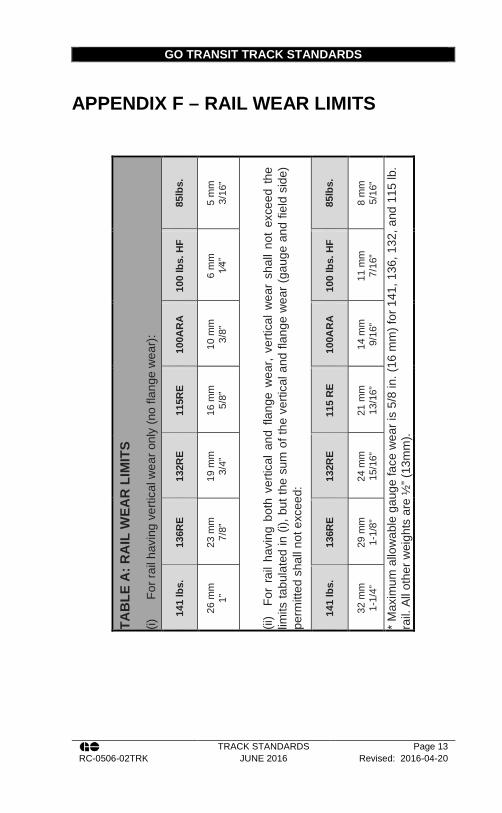
GO TRANSIT TRACK STANDARDS
TRACK STANDARDS Page 13 RC-0506-02TRK JUNE 2016 Revised: 2016-04-20
APPENDIX F – RAIL WEAR LIMITS TA
BLE
A: R
AIL
WEA
R L
IMIT
S (i)
Fo
r rai
l hav
ing
verti
cal w
ear o
nly
(no
flang
e w
ear)
:
85lb
s.
5 m
m
3/16
”
(ii)
For
rai
l hav
ing
both
ver
tical
and
fla
nge
wea
r, ve
rtica
l wea
r sh
all n
ot e
xcee
d th
e lim
its ta
bula
ted
in (i
), bu
t the
sum
of t
he v
ertic
al a
nd fl
ange
wea
r (ga
uge
and
field
sid
e)
perm
itted
sha
ll no
t exc
eed:
85lb
s.
8 m
m
5/16
”
* M
axim
um a
llow
able
gau
ge fa
ce w
ear i
s 5/
8 in
. (16
mm
) for
141
, 136
, 132
, and
115
lb.
rail.
All
othe
r wei
ghts
are
½” (
13m
m).
100
lbs.
HF
6 m
m
1⁄4”
100
lbs.
HF
11 m
m
7/16
”
100A
RA
10 m
m
3/8”
100A
RA
14 m
m
9/16
”
115R
E
16 m
m
5/8”
115
RE
21 m
m
13/1
6”
132R
E
19 m
m
3/4”
132R
E
24 m
m
15/1
6”
136R
E
23 m
m
7/8”
136R
E
29 m
m
1-1/
8”
141
lbs.
26 m
m
1”
141
lbs.
32 m
m
1-1/
4”
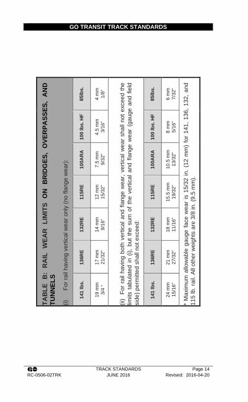
GO TRANSIT TRACK STANDARDS
TRACK STANDARDS Page 14 RC-0506-02TRK JUNE 2016 Revised: 2016-04-20
TA
BLE
B:
RA
IL W
EAR
LIM
ITS
ON
BR
IDG
ES,
OVE
RPA
SSES
, A
ND
TU
NN
ELS
(i)
For r
ail h
avin
g ve
rtica
l wea
r onl
y (n
o fla
nge
wea
r):
85lb
s.
4 m
m
1/8”
(ii)
For
rai
l hav
ing
both
ver
tical
and
flan
ge w
ear,
verti
cal w
ear
shal
l not
exc
eed
the
limits
tab
ulat
ed in
(i),
but
the
sum
of
the
verti
cal a
nd f
lang
e w
ear
(gau
ge a
nd f
ield
si
de) p
erm
itted
sha
ll no
t exc
eed:
85lb
s.
6 m
m
7/32
”
* M
axim
um a
llow
able
gau
ge fa
ce w
ear
is 1
5/32
in. (
12 m
m)
for
141,
136
, 132
, and
11
5 lb
. rai
l. Al
l oth
er w
eigh
ts a
re 3
/8 in
. (9.
5 m
m).
100
lbs.
HF
4.5
mm
3/
16”
100
lbs.
HF
8 m
m
5/16
”
100A
RA
7.5
mm
9/
32”
100A
RA
10.5
mm
13
/32”
115R
E
12 m
m
15/3
2”
115R
E
15.5
mm
19
/32”
132R
E
14 m
m
9/16
”
132R
E
18 m
m
11/1
6”
136R
E
17 m
m
21/3
2”
136R
E
21 m
m
27/3
2”
141
lbs.
19 m
m
3/4
“
141
lbs.
24 m
m
15/1
6”

GO TRANSIT TRACK STANDARDS
TRACK STANDARDS Page 15 RC-0506-02TRK JUNE 2016 Revised: 2016-04-20
APPENDIX G – RAIL DEFECT DESCRIPTIONS TRANSVERSE DEFECTS – TDT, TDW, TDC, TDD
Transverse fissure, showing rapid growth
Transverse fissure, showing sudden growth
Appearance of transverse defects in track
No evidence of a transverse defect is visible until the separation has reached the rail surface (cracks out). One or more of the following may then recognize a transverse defect:
1. A hairline crack at right angles to the running surface, usually on the field or gauge side of the head or at the fillet under the head.
2. Bleeding around the crack. 3. A hairline crack at the gauge corner of the rail head. A
rail that has been turned may have a crack on the field side. Numerous cracks on the gauge corner are often present but should cause no suspicion unless a single
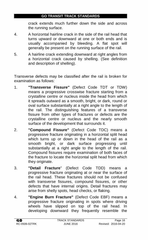
GO TRANSIT TRACK STANDARDS
TRACK STANDARDS Page 16 RC-0506-02TRK JUNE 2016 Revised: 2016-04-20
crack extends much further down the side and across the running surface.
4. A horizontal hairline crack in the side of the rail head that turns upward or downward at one or both ends and is usually accompanied by bleeding. A flat spot will generally be present on the running surface of the rail.
5. A hairline crack extending downward at right angles from a horizontal crack caused by shelling. (See definition and description of shelling).
Transverse defects may be classified after the rail is broken for examination as follows: 1. "Transverse Fissure" (Defect Code TDT or TDW)
means a progressive crosswise fracture starting from a crystalline centre or nucleus inside the head from which it spreads outward as a smooth, bright, or dark, round or oval surface substantially at a right angle to the length of the rail. The distinguishing features of a transverse fissure from other types of fractures or defects are the crystalline centre or nucleus and the nearly smooth surface of the development that surrounds it.
2. "Compound Fissure" (Defect Code TDC) means a progressive fracture originating in a horizontal split head which turns up or down in the head of the rail as a smooth bright, or dark surface progressing until substantially at a right angle to the length of the rail. Compound fissures require examination of both faces of the fracture to locate the horizontal split head from which they originate.
3. "Detail Fracture" (Defect Code TDD) means a progressive fracture originating at or near the surface of the rail head. These fractures should not be confused with transverse fissures, compound fissures, or other defects that have internal origins. Detail fractures may arise from shelly spots, head checks, or flaking.
4. "Engine Burn Fracture" (Defect Code EBF) means a progressive fracture originating in spots where driving wheels have slipped on top of the rail head. In developing downward they frequently resemble the

GO TRANSIT TRACK STANDARDS
TRACK STANDARDS Page 17 RC-0506-02TRK JUNE 2016 Revised: 2016-04-20
compound or even transverse fissures with which they should not be confused or classified.
This type of defect is usually caused by imperfections in the rail steel when rolled. In non-control-cooled rail and chrome rail, a transverse defect is commonly caused by shatter crack from hydrogen. If one crack is found, there are likely to be many others in the same rail. Defects are defined in the definition section, however a description of their appearance in track is below:
Engine Burn (EBF)
Appearance in Track: An oval or round dark area on the running surface of the rail where damaged metal breaks out forming a cavity. There are usually several marks. Sometimes they match on both rails. Others are located on the same rail and spaced at a distance corresponding to the spacing of the locomotive wheels.
Shelly Rail
Appearance in Track: 1. Dark spots irregularly spaced on
the gauge side of the running surface.
2. Longitudinal separations at one or more levels in the upper gauge corner
3. It occurs most frequently on curves.
Shelly Rail is not to be confused with spalling from burnt steel in chrome rail, which is a type of mill defect. Spalling from burnt steel will show up within a few days after the rail is laid. Shell will not occur till rail has carried substantial traffic.

GO TRANSIT TRACK STANDARDS
TRACK STANDARDS Page 18 RC-0506-02TRK JUNE 2016 Revised: 2016-04-20
Split Web (SWJ, SWO)
Appearance in Track: Bleeding cracks in the web Note: This type of failure is frequently caused by bruises on the web resulting from striking the web with a spike maul or other object. Long splits in the web of new or nearly new rail are likely to be a manufacturing defect from roller straightening.
Horizontal Split Head (HSH, HSJ)
Appearance in Track: 1. Before cracking out, a horizontal
split head will cause the appearance of a flat spot on the running surface. There may be a slight widening of the rail head.
2. After cracking out, a horizontal split head will appear as a hairline crack in the side of the head on one or both sides of the rail at least 1/3 of the depth of head below the top of the rail. In rail laid without tie plates, the crack will usually appear on the gauge side and in rail laid with tie plates, on the field side.
Note: This type of failure is caused by a manufacturing defect
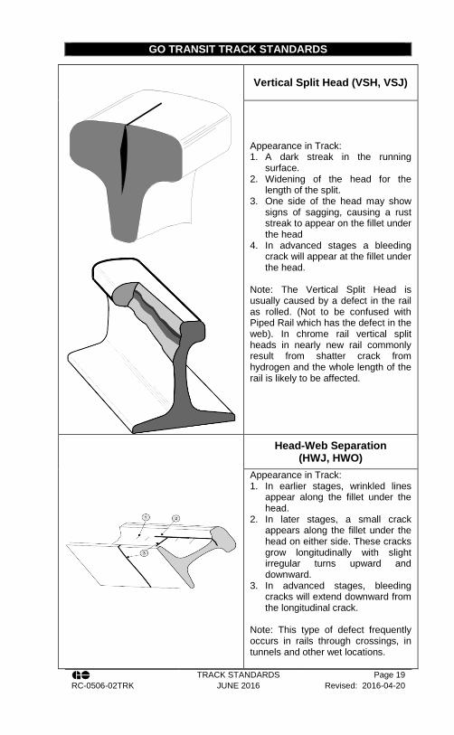
GO TRANSIT TRACK STANDARDS
TRACK STANDARDS Page 19 RC-0506-02TRK JUNE 2016 Revised: 2016-04-20
Vertical Split Head (VSH, VSJ)
Appearance in Track: 1. A dark streak in the running
surface. 2. Widening of the head for the
length of the split. 3. One side of the head may show
signs of sagging, causing a rust streak to appear on the fillet under the head
4. In advanced stages a bleeding crack will appear at the fillet under the head.
Note: The Vertical Split Head is usually caused by a defect in the rail as rolled. (Not to be confused with Piped Rail which has the defect in the web). In chrome rail vertical split heads in nearly new rail commonly result from shatter crack from hydrogen and the whole length of the rail is likely to be affected.
Head-Web Separation (HWJ, HWO)
Appearance in Track: 1. In earlier stages, wrinkled lines
appear along the fillet under the head.
2. In later stages, a small crack appears along the fillet under the head on either side. These cracks grow longitudinally with slight irregular turns upward and downward.
3. In advanced stages, bleeding cracks will extend downward from the longitudinal crack.
Note: This type of defect frequently occurs in rails through crossings, in tunnels and other wet locations.

GO TRANSIT TRACK STANDARDS
TRACK STANDARDS Page 20 RC-0506-02TRK JUNE 2016 Revised: 2016-04-20
Bolt Hole Break (BHJ, BHO)
Appearance in Track: Cracks in the web extending radially from a bolt hole. Note: This type of failure is frequently caused by loose bolts in the joint or inadequate anchoring of the track causing the bolts to strike the sides of the hole and damage the metal.
Crushed Head / Flattened Rail (CHJ, CHO)
Appearance in Track: 1. A flattening and widening of the
head with the entire head sagging,
2. Small cracks in the depression of the running surface.
3. In advanced stages, a bleeding crack may appear in the fillet under the head.
Piped Rail (PRJ, PRO)
Appearance in Track: 1. Bulging of the web on either or
both sides. There may be shallow cracks apparent on the sides of the bulge.
2. A slight sinking of the rail head in the area above the pipe with no other deformation of the head.
Note: This type of failure is due to a manufacturing defect.
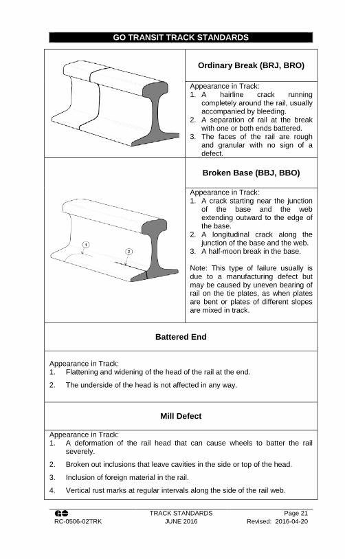
GO TRANSIT TRACK STANDARDS
TRACK STANDARDS Page 21 RC-0506-02TRK JUNE 2016 Revised: 2016-04-20
Ordinary Break (BRJ, BRO)
Appearance in Track: 1. A hairline crack running
completely around the rail, usually accompanied by bleeding.
2. A separation of rail at the break with one or both ends battered.
3. The faces of the rail are rough and granular with no sign of a defect.
Broken Base (BBJ, BBO)
Appearance in Track: 1. A crack starting near the junction
of the base and the web extending outward to the edge of the base.
2. A longitudinal crack along the junction of the base and the web.
3. A half-moon break in the base. Note: This type of failure usually is due to a manufacturing defect but may be caused by uneven bearing of rail on the tie plates, as when plates are bent or plates of different slopes are mixed in track.
Battered End
Appearance in Track: 1. Flattening and widening of the head of the rail at the end.
2. The underside of the head is not affected in any way.
Mill Defect
Appearance in Track: 1. A deformation of the rail head that can cause wheels to batter the rail
severely.
2. Broken out inclusions that leave cavities in the side or top of the head.
3. Inclusion of foreign material in the rail.
4. Vertical rust marks at regular intervals along the side of the rail web.
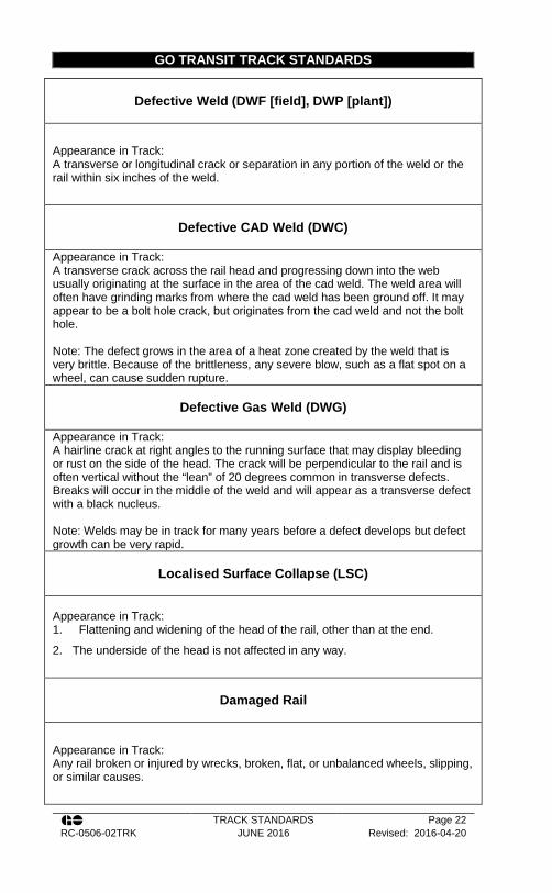
GO TRANSIT TRACK STANDARDS
TRACK STANDARDS Page 22 RC-0506-02TRK JUNE 2016 Revised: 2016-04-20
Defective Weld (DWF [field], DWP [plant])
Appearance in Track: A transverse or longitudinal crack or separation in any portion of the weld or the rail within six inches of the weld.
Defective CAD Weld (DWC)
Appearance in Track: A transverse crack across the rail head and progressing down into the web usually originating at the surface in the area of the cad weld. The weld area will often have grinding marks from where the cad weld has been ground off. It may appear to be a bolt hole crack, but originates from the cad weld and not the bolt hole. Note: The defect grows in the area of a heat zone created by the weld that is very brittle. Because of the brittleness, any severe blow, such as a flat spot on a wheel, can cause sudden rupture.
Defective Gas Weld (DWG)
Appearance in Track: A hairline crack at right angles to the running surface that may display bleeding or rust on the side of the head. The crack will be perpendicular to the rail and is often vertical without the “lean” of 20 degrees common in transverse defects. Breaks will occur in the middle of the weld and will appear as a transverse defect with a black nucleus. Note: Welds may be in track for many years before a defect develops but defect growth can be very rapid.
Localised Surface Collapse (LSC)
Appearance in Track: 1. Flattening and widening of the head of the rail, other than at the end.
2. The underside of the head is not affected in any way.
Damaged Rail
Appearance in Track: Any rail broken or injured by wrecks, broken, flat, or unbalanced wheels, slipping, or similar causes.

GO TRANSIT TRACK STANDARDS
TRACK STANDARDS Page 23 RC-0506-02TRK JUNE 2016 Revised: 2016-04-20
Damage by Defective Rolling Stock
Appearance in Track: Nicks, cuts, dents or scars on any part of the surface of the rail.
Damage by Derailment
Appearance in Track: Rail that has been broken, bent, nicked or otherwise damaged by derailment of equipment. Rail defects caused by derailments will have defect codes which reflect the type of defect the derailment created, i.e.: BBJ, BRO, TDT…etc.

GO TRANSIT TRACK STANDARDS
TRACK STANDARDS Page 24 RC-0506-02TRK JUNE 2016 Revised: 2016-04-20
APPENDIX H – REMEDIAL ACTION FOR RAIL DEFECTS Table 41 – Rail Defects on Class 1, 2, and 3 Track with
Less Than 20 MGT Annually
Defect
Percent of rail head cross-
sectional area weakened by
the defect
If the defective rail is not replaced
immediately, take the following
remedial action denoted by note:
Traverse or
Compound Fissure
0 to 70 B 71 to 99 A2
100 A
Detail or Engine Burn
Fracture or Defective
Weld
0 to 20 C 21 to 80 D 81 to 99 A2 or (E and H)
100 A or (E and H)
Defect Defect Size in. (mm)
If the defective rail is not replaced
immediately, take the following
remedial action denoted by note:
Vertical or Horizontal Split Head
0 to 2 (0 - 51) H and F Over 2 to 4 (>51 – 102) I and G
Over 4 (>102) B Break out in rail
head A
Split Web, Piped Rail,
or Head Web
Separation
0 to ½ (0 – 13) H and F Over ½ to 3 (>13 – 76) I and G
Over 3 (>76) B Break out in rail
head A
Bolt Hole Crack
0 to ½ (0 – 13) H and F Over ½ to 1½
(>13 – 38) I and G
Over 1½ (>38) B Break out in rail
head A
Broken Rail Base
0 to 6 (0 – 152) D Over 6 (>152) A or (E and I)
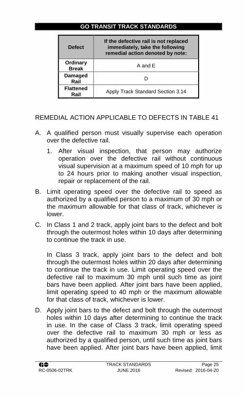
GO TRANSIT TRACK STANDARDS
TRACK STANDARDS Page 25 RC-0506-02TRK JUNE 2016 Revised: 2016-04-20
Defect If the defective rail is not replaced
immediately, take the following remedial action denoted by note:
Ordinary Break A and E
Damaged Rail D
Flattened Rail Apply Track Standard Section 3.14
REMEDIAL ACTION APPLICABLE TO DEFECTS IN TABLE 41
A. A qualified person must visually supervise each operation over the defective rail. 1. After visual inspection, that person may authorize
operation over the defective rail without continuous visual supervision at a maximum speed of 10 mph for up to 24 hours prior to making another visual inspection, repair or replacement of the rail.
B. Limit operating speed over the defective rail to speed as authorized by a qualified person to a maximum of 30 mph or the maximum allowable for that class of track, whichever is lower.
C. In Class 1 and 2 track, apply joint bars to the defect and bolt through the outermost holes within 10 days after determining to continue the track in use. In Class 3 track, apply joint bars to the defect and bolt through the outermost holes within 20 days after determining to continue the track in use. Limit operating speed over the defective rail to maximum 30 mph until such time as joint bars have been applied. After joint bars have been applied, limit operating speed to 40 mph or the maximum allowable for that class of track, whichever is lower.
D. Apply joint bars to the defect and bolt through the outermost holes within 10 days after determining to continue the track in use. In the case of Class 3 track, limit operating speed over the defective rail to maximum 30 mph or less as authorized by a qualified person, until such time as joint bars have been applied. After joint bars have been applied, limit
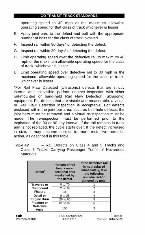
GO TRANSIT TRACK STANDARDS
TRACK STANDARDS Page 26 RC-0506-02TRK JUNE 2016 Revised: 2016-04-20
operating speed to 40 mph or the maximum allowable operating speed for that class of track whichever is lesser.
E. Apply joint bars to the defect and bolt with the appropriate number of bolts for the class of track involved.
F. Inspect rail within 90 days* of detecting the defect. G. Inspect rail within 30 days* of detecting the defect. H. Limit operating speed over the defective rail to maximum 40
mph or the maximum allowable operating speed for the class of track, whichever is lesser.
I. Limit operating speed over defective rail to 30 mph or the maximum allowable operating speed for the class of track, whichever is lesser.
*For Rail Flaw Detected (Ultrasonic) defects that are strictly internal and not visible, perform another inspection with either rail-mounted or hand-held Rail Flaw Detection (ultrasonic) equipment. For defects that are visible and measurable, a visual or Rail Flaw Detection inspection is acceptable. For defects enclosed within the joint bar area, such as bolt-hole defects, the joint bars must be removed and a visual re-inspection must be made. The re-inspection must be performed prior to the expiration of the 30 or 90 day interval. If the rail remains in track and is not replaced, the cycle starts over. If the defect increased in size, it may become subject to more restrictive remedial action, as described in this table.
Table 42 – Rail Defects on Class 4 and 5 Tracks and Class 3 Tracks Carrying Passenger Traffic of Hazardous Materials
Defect1
Percent of rail head cross-
sectional area weakened by
the defect
If the defective rail is not replaced
immediately, take the following
remedial action denoted by note:
Traverse or Compound
Fissure
0 to 70 1 71 to 99 2
100 3 Detail or
Engine Burn Fracture or Defective
Weld
0 to 25 4
26 to 60 5 61 to 99 6
100 3

GO TRANSIT TRACK STANDARDS
TRACK STANDARDS Page 27 RC-0506-02TRK JUNE 2016 Revised: 2016-04-20
Defect1 Defect Size in. (mm)
If the defective rail is not replaced
immediately, take the following
remedial action denoted by note:
Vertical or Horizontal
Split Head, or Horizontal Split Web, Piped Rail, Head-Web
Separations, Defective Weld, or
Longitudinal
0 to 2 (0 - 51) 7
Over 2 to 4 (>51 – 102) 8
Over 4 (>102) 9
Break out in rail head 3
Bolt Hole Crack
0 to ½ (0 – 13) 7 Over ½ to 1½
(>13 – 38) 8
Over 1½ (>38) 9 Break out in rail
head 3
Broken Rail Base
0 to 6 (0 – 152) 10 Over 6 (>152) 11
Defect1 If the defective rail is not replaced
immediately, take the following remedial action denoted by note:
Ordinary Break 3
Damaged Rail 12
Flattened Rail Apply Track Standard Section 3.14
1 Defects in special track-work or highway crossings must be protected as per the above inspected visually at the minimum frequency required by regulation for track inspections and removed within 14 days.
REMEDIAL ACTION APPLICABLE TO DEFECTS IN TABLE 42
1. Inspect defect immediately. Limit operating speed to maximum 30 mph. Remove defect within 7 days of being detected.

GO TRANSIT TRACK STANDARDS
TRACK STANDARDS Page 28 RC-0506-02TRK JUNE 2016 Revised: 2016-04-20
2. Assign a qualified person to make a visual inspection once every 24 hours. Limit operating speed to 10 mph. Remove defect within 72 hours of being detected.
3. Assign a qualified person to visually supervise each train movement over the defective rail.
4. Inspect defect. Apply joint bars and bolt through outer most holes. Limit operating speed to 30 mph until joint bars are applied. Thereafter, limit operating speed to 50 mph or the maximum for the class of track, whichever is more restrictive. Remove defect within 7 days of being detected.
5. Inspect defect. Apply joint bars and bolt through outer most holes. Limit operating speed to 30 mph as authorized by a qualified person until joint bars are applied. Thereafter, limit operating speed to 50 mph or the maximum for the class of track, whichever is more restrictive. Remove defect within 72 hours of being detected.
6. Inspect defect. Apply joint bars to the defect. Limit operating speed to 10 mph until joint bars are applied. Thereafter, limit operating speed to 50 mph or the maximum for the class of track, whichever is more restrictive. Remove defect within 24 hours of being detected.
7. Inspect immediately. Limit operating speed to a maximum of 50 mph. Remove defect within 7 days of being detected.
8. Inspect immediately. Limit operating speed to a maximum of 30 mph. Remove defect within 72 hours of being detected.
9. Inspect immediately. Limit operating speed to a maximum of 10 mph. Remove defect within 48 hours of being detected.
10. Inspect immediately. Limit operating speed to a maximum of 30 mph. Apply joint bars to the defect and fully bolt for class of track within 3 days. Remove defect within 72 hours of being detected.
11. Inspect immediately. Limit operating speed to 10 mph until repaired. Assign a qualified person to visually

GO TRANSIT TRACK STANDARDS
TRACK STANDARDS Page 29 RC-0506-02TRK JUNE 2016 Revised: 2016-04-20
supervise each train movement over the defective rail until a repair has been completed.
12. Inspect immediately. Apply joint bars within 10 days. Limit operating speed to a maximum of 30 mph until joint bars are applied. Thereafter, limit the operating speed to 50 mph.
Table 43 Corrective and Remedial Actions for Single Surface Irregularities
Condition Depth Remedial Action Corrective action
Crack-out in the upper fillet
under the rail head
N/A
Limit train operations to not more than 10mph and visually supervise each movement until the defective rail is removed
Change out rail
Corrugation All depths Record Location
Grind with local welding forces, switch & crossing grinder or grinding train if possible, or change rail
Flaking N/A Record Location
Grind with local welding forces, switch & crossing grinder or grinding train
Spalling and
Shelling
≤ 3mm (1/8”)
Record Location and check for escalation of defect once per month
Grind with local welding forces, switch & crossing grinder or grinding train
> 3mm (1/8” ) ≤ 5 mm (3/16“)
Record Location and check for crack-out under head once per week
Change out rail
>5 mm (3/16“) ≤7mm ( ¼“)
Limit train operation to not more than 60mph and check for crack-out under head once per week
Change out rail
>7mm ( ¼ ”)
Limit train operations to not more than 30mph and check for crack-out under head on each routine
Change out rail
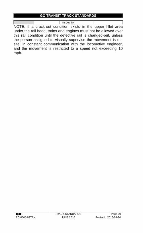
GO TRANSIT TRACK STANDARDS
TRACK STANDARDS Page 30 RC-0506-02TRK JUNE 2016 Revised: 2016-04-20
inspection NOTE: If a crack-out condition exists in the upper fillet area under the rail head, trains and engines must not be allowed over this rail condition until the defective rail is changed-out, unless the person assigned to visually supervise the movement is on-site, in constant communication with the locomotive engineer, and the movement is restricted to a speed not exceeding 10 mph.
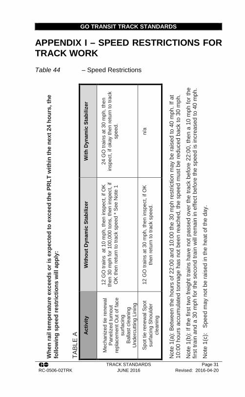
GO TRANSIT TRACK STANDARDS
TRACK STANDARDS Page 31 RC-0506-02TRK JUNE 2016 Revised: 2016-04-20
APPENDIX I – SPEED RESTRICTIONS FOR TRACK WORK Table 44 – Speed Restrictions
Whe
n ra
il te
mpe
ratu
re e
xcee
ds o
r is
expe
cted
to e
xcee
d th
e PR
LT w
ithin
the
next
24
hour
s, th
e fo
llow
ing
spee
d re
stric
tions
will
app
ly:
TABL
E A
W
ith D
ynam
ic S
tabi
lizer
24 G
O tr
ains
at 3
0 m
ph, t
hen
insp
ect,
if ok
ay th
en re
turn
to tr
ack
spee
d.
n/a
Not
e 1(
a): B
etw
een
the
hour
s of
22:
00 a
nd 1
0:00
the
30 m
ph re
stric
tion
may
be
rais
ed to
40
mph
. If a
t 10
:00
hour
s ac
cum
ulat
ed to
nnag
e ha
s no
t bee
n re
ache
d, th
e sp
eed
mus
t be
redu
ced
back
to 3
0 m
ph.
Not
e 1(
b): I
f the
firs
t tw
o fre
ight
trai
ns h
ave
not p
asse
d ov
er th
e tra
ck b
efor
e 22
:00,
then
a 1
0 m
ph fo
r the
fir
st tr
ain
and
a 30
mph
for t
he s
econ
d tra
in w
ill re
mai
n in
effe
ct b
efor
e th
e sp
eed
is in
crea
sed
to 4
0 m
ph.
Not
e 1(
c):
Spe
ed m
ay n
ot b
e ra
ised
in th
e he
at o
f the
day
.
With
out D
ynam
ic S
tabi
lizer
12 G
O tr
ains
at 1
0 m
ph, t
hen
insp
ect,
if O
K
then
30
mph
for 1
00,0
00 to
ns, t
hen
insp
ect,
if O
K th
en re
turn
to tr
ack
spee
d * S
ee N
ote
1
12 G
O tr
ains
at 3
0 m
ph, t
hen
insp
ect,
if O
K
then
retu
rn to
trac
k sp
eed.
Act
ivity
Mec
hani
zed
tie re
new
al
Pan
eliz
ed tu
rnou
t re
plac
emen
t Out
of f
ace
surfa
cing
B
alla
st c
lean
ing
Und
ercu
tting
Lin
ing
Spo
t tie
rene
wal
Spo
t su
rfaci
ng S
houl
der
clea
ning
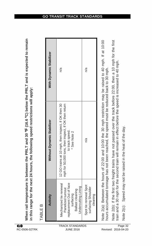
GO TRANSIT TRACK STANDARDS
TRACK STANDARDS Page 32 RC-0506-02TRK JUNE 2016 Revised: 2016-04-20
W
hen
rail
tem
pera
ture
is b
etw
een
the
PRLT
and
30
ºF (1
6.6
ºC) b
elow
the
PRLT
and
is e
xpec
ted
to re
mai
n in
this
rang
e fo
r the
nex
t 24
hour
s, th
e fo
llow
ing
spee
d re
stric
tions
will
app
ly:
TABL
E B
With
Dyn
amic
Sta
biliz
er
n/a
n/a
Not
e 2(
a): B
etw
een
the
hour
s of
22:
00 a
nd 1
0:00
the
30 m
ph r
estri
ctio
n m
ay b
e ra
ised
to 4
0 m
ph. I
f at 1
0:00
ho
urs
accu
mul
ated
tonn
age
has
not b
een
reac
hed,
the
spee
d m
ust b
e re
duce
d ba
ck to
30
mph
. N
ote
2(b)
: If t
he fi
rst t
wo
freig
ht tr
ains
hav
e no
t pas
sed
over
the
track
bef
ore
22:0
0, th
en a
10
mph
for
the
first
tra
in a
nd a
30
mph
for t
he s
econ
d tra
in w
ill re
mai
n in
effe
ct b
efor
e th
e sp
eed
is in
crea
sed
to 4
0 m
ph.
Not
e 2(
c):
Spe
ed m
ay n
ot b
e ra
ised
in th
e he
at o
f the
day
.
With
out D
ynam
ic S
tabi
lizer
12 G
O tr
ains
at 1
0 m
ph, t
hen
insp
ect,
if O
K th
en 3
0 m
ph fo
r 50,
000
tons
, the
n in
spec
t, if
OK
then
retu
rn
to tr
ack
spee
d.
* S
ee N
ote
2
n/a
Act
ivity
Mec
hani
zed
tie re
new
al
Pan
eliz
ed tu
rnou
t re
plac
emen
t Out
of f
ace
surfa
cing
B
alla
st c
lean
ing
Und
ercu
tting
Lin
ing
Spo
t tie
rene
wal
Spo
t su
rfaci
ng S
houl
der
clea
ning

GO TRANSIT TRACK STANDARDS
TRACK STANDARDS Page 33 RC-0506-02TRK JUNE 2016 Revised: 2016-04-20
Whe
n ra
il te
mpe
ratu
re is
30
ºF (
16.6
ºC
) or
mor
e be
low
the
PR
LT a
nd is
exp
ecte
d to
rem
ain
in t
his
rang
e fo
r the
nex
t 24
hour
s, th
e fo
llow
ing
spee
d re
stric
tions
will
app
ly:
TABL
E C
With
Dyn
amic
Sta
biliz
er
n/a
n/a
With
out D
ynam
ic S
tabi
lizer
12 G
O tr
ains
at 3
0 m
ph, t
hen
insp
ect,
if O
K re
turn
to
trac
k sp
eed.
n/a
Act
ivity
Mec
hani
zed
tie re
new
al
Pan
eliz
ed tu
rnou
t re
plac
emen
t Out
of f
ace
surfa
cing
B
alla
st c
lean
ing
Und
ercu
tting
Lin
ing
Spo
t tie
rene
wal
Spo
t su
rfaci
ng S
houl
der
clea
ning
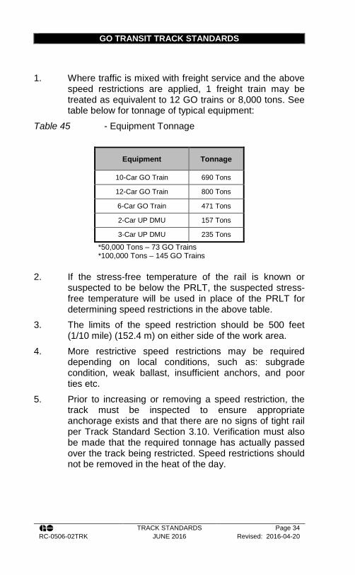
GO TRANSIT TRACK STANDARDS
TRACK STANDARDS Page 34 RC-0506-02TRK JUNE 2016 Revised: 2016-04-20
1. Where traffic is mixed with freight service and the above speed restrictions are applied, 1 freight train may be treated as equivalent to 12 GO trains or 8,000 tons. See table below for tonnage of typical equipment:
Table 45 - Equipment Tonnage
Equipment Tonnage
10-Car GO Train 690 Tons
12-Car GO Train 800 Tons
6-Car GO Train 471 Tons
2-Car UP DMU 157 Tons
3-Car UP DMU 235 Tons
*50,000 Tons – 73 GO Trains *100,000 Tons – 145 GO Trains
2. If the stress-free temperature of the rail is known or suspected to be below the PRLT, the suspected stress-free temperature will be used in place of the PRLT for determining speed restrictions in the above table.
3. The limits of the speed restriction should be 500 feet (1/10 mile) (152.4 m) on either side of the work area.
4. More restrictive speed restrictions may be required depending on local conditions, such as: subgrade condition, weak ballast, insufficient anchors, and poor ties etc.
5. Prior to increasing or removing a speed restriction, the track must be inspected to ensure appropriate anchorage exists and that there are no signs of tight rail per Track Standard Section 3.10. Verification must also be made that the required tonnage has actually passed over the track being restricted. Speed restrictions should not be removed in the heat of the day.

GO TRANSIT TRACK STANDARDS
TRACK STANDARDS Page 35 RC-0506-02TRK JUNE 2016 Revised: 2016-04-20
APPENDIX J – CONTINUOUS WELDED RAIL THERMAL EXPANSION CHART Determination of rail expansion for lengths between those shown in the Table can be done through averaging rail lengths that bound the intermediate length and rounding to the nearest 1/8th inch or 1 mm.
LEN
GTH
OF
CW
R f
t. (m
) 14
82 (4
52)
CW
R M
OVE
MEN
T in
. (m
m)
5/8
(15)
1-1/
8 (2
9)
1-3/
4 (4
4)
2-3/
8 (6
0)
3 (7
6)
3-1/
2 (8
9)
4-1/
8 (1
05)
4-3/
4 (1
21)
5-3/
8 (1
37)
5-7/
8 (1
49)
6-1⁄
2 (1
65)
7-1/
8 (1
81)
1400
(427
)
1/2
(13)
1-1/
8 (2
9)
1-5/
8 (4
1)
2-1/
4 (5
7)
2-3/
4 (7
5)
3-3/
8 (8
4)
3-7/
8 (9
8)
4-1/
2 (1
14)
5 (1
27)
5-5/
8 (1
43)
6-1/
8 (1
56)
6-3/
4 (1
71)
1200
(366
)
1/2
(13)
1 (2
5)
1-1/
2 (3
8)
1-7/
8 (4
8)
2-3/
8 (6
0)
2-7/
8 (7
3)
3-3/
8 (8
4)
3-7/
8 (9
8)
4-3/
8 (1
11)
4-3/
4 (1
21)
5-1/
4 (1
33)
5-3/
4 (1
46)
1000
(305
)
3/8
(10)
3/4
(20)
1-1/
4 (3
2)
1-5/
8 (4
1)
2 (5
1)
2-3/
8 (6
0)
2-3/
4 (7
5)
3-1/
4 (8
3)
3-5
/8 (9
2)
4 (1
02)
4-3/
8 (1
11)
4-3/
4 (1
21)
800
(244
)
3/8
(10)
5/8
(15)
1 (2
5)
1-1/
4 (3
2)
1-5/
8 (4
1)
1-7/
8 (4
8)
2-1/
4 (5
7)
2-1/
2 (6
4)
2-7/
8 (7
3)
3-1
/4 (8
3)
3-1/
2 (8
9)
3-7/
8 (9
8)
600
(183
)
1/4
(6)
1/2
(13)
3/4
(20)
1 (2
5)
1-1/
4 (3
2)
1-1/
2 (3
8)
1-5/
8 (4
1)
1-7/
8 (4
8)
2-1/
8 (5
4)
2-3/
8 (6
0)
2-5/
8 (6
7)
2-7/
8 (7
3)
400
(122
)
1/8
(3)
3/8
(10)
1/2
(13)
5/8
(15)
3/4
(20)
1 (2
5)
1-1/
8 (2
9)
1-1/
4 (3
2)
1-1/
2 (3
8)
1-5/
8 (4
1)
1-3/
4 (4
4)
1-7/
8 (4
8)
200
(61)
1/8
(3)
1/8
(3)
1/4
(6)
3/8
(10)
3/8
(10)
1/2
(13)
1/2
(13)
5/8
(15)
3/4
(20)
3/4
(20)
7/8
(23)
1 (2
5)
TEM
P.
Diff
eren
ce
from
PR
LT
°C
2 5 7 9 11
13
16
18
20
22
24
27
°F
5 10
15
20
25
30
35
40
45
50
55
60

GO TRANSIT TRACK STANDARDS
TRACK STANDARDS Page 36 RC-0506-02TRK JUNE 2016 Revised: 2016-04-20
LE
NG
TH O
F C
WR
ft.
(m)
1482
(452
)
CW
R M
OVE
MEN
T in
. (m
m)
7-3/
4 (1
97)
8-1/
4 (2
10)
8-7/
8 (2
25)
9-1/
2 (2
41)
10-1
/8 (2
57)
10-5
/8 (2
70)
11-1
/4 (2
86)
11-7
/8 (3
02)
12-1
/2 (3
18)
13 (3
30)
MO
VEM
EN
T (in
) = R
AIL
LEN
GTH
(ft)
x TE
MP
DIF
F FR
OM
PR
LT (°
F) x
0.0
0008
M
OVE
ME
NT
(mm
) = R
AIL
LEN
GTH
(m) x
TEM
P D
IFF
FRO
M P
RLT
( °C
) x 0
.014
5 1400
(427
)
7-1/
4 (1
84)
7-7/
8 (2
00)
8-3/
8 (2
13)
9 (2
29)
9-1/
2 (2
41)
10-1
/8 (2
57)
10-5
/8 (2
70)
11-1
/4 (2
86)
11-3
/4 (2
98)
12-3
/8 (3
14)
1200
(366
)
6-1/
4 (1
59)
6-3/
4 (1
71)
7-1/
4 (1
84)
7-5/
8 (1
94)
8-1/
8 (2
06)
8-5/
8 (2
19)
9-1/
8 (2
32)
9-5/
8 (2
44)
10-1
/8 (2
57)
10-1
/2 (2
67)
1000
(305
)
5-1/
4 (1
33)
5-5/
8 (1
43)
6 (1
52)
6-3/
8 (1
62)
6-3/
4 (1
71)
7-1/
4 (1
84)
7-5/
8 (1
94)
8 (2
03)
8-3/
8 (2
13)
8-3/
4 (2
22)
800
(244
)
4-1/
8 (1
05)
4-1/
2 (1
14)
4-3/
4 (1
21)
5-1/
8 (1
30)
5-1/
2 (1
40)
5-3/
4 (1
46)
6-1/
8 (1
56)
6-3/
8 (1
62)
6-3/
4 (1
71)
7 (1
78)
600
(183
)
3-1/
8 (7
9)
3-3/
8 (8
6)
3-5/
8 (9
2)
3-7/
8 (9
8)
4-1/
8 (1
05)
4-3/
8 (1
11)
4-1/
2 (1
14)
4-3/
4 (1
21)
5 (1
27)
5-1/
4 (1
33)
400
(122
)
2-1/
8 (5
4)
2-1/
4 (6
4)
2-3/
8 (6
0)
2-1/
2 (6
4)
2-3/
4 (7
0)
2-7/
8 (7
3)
3 (7
6)
3-1/
4 (8
3)
3-3/
8 (8
6)
3-1/
2 (8
9)
200
(61)
1 (2
5)
1-1/
8 (2
9)
1-1/
4 (3
2)
1-1/
4 (3
2)
1-3/
8 (3
5)
1-1/
2 (3
8)
1-1/
2 (3
8)
1-5/
8 (4
1)
1-5/
8 (4
1)
1-3/
4 (4
4)
TEM
P.
Diff
eren
ce
from
PR
LT
°C
29
31
33
36
38
40
42
44
47
49
°F
65
70
75
80
85
90
95
100
105
110

GO TRANSIT TRACK STANDARDS
TRACK STANDARDS Page 37 RC-0506-02TRK JUNE 2016 Revised: 2016-04-20
Temperature differential from the PRLT
Length of Rail ft. (m)
500 (152)
Adjustment Required in. (mm) ° F °C
5 2 1/8 (3)
10 5 3/8 (10)
15 7 5/8 (15)
20 9 7/8 (23)
25 11 1 (25)
30 13 1-1/4 (32)
35 16 1-3/8 (35)
40 18 1-5/8 (41)
45 20 1-7/8 (48)
50 22 2 (51)
55 24 2-1/4 (57)
60 27 2-3/8 (60)
65 29 2-5/8 (67)
70 31 2-7/8 (73)
75 33 3 (76)
80 36 3-1/8 (79)
85 38 3-1/2 (89)
90 40 3-5/8 (92)
95 42 3-3/4 (95)
100 44 4 (101)
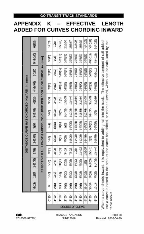
GO TRANSIT TRACK STANDARDS
TRACK STANDARDS Page 38 RC-0506-02TRK JUNE 2016 Revised: 2016-04-20
APPENDIX K – EFFECTIVE LENGTH ADDED FOR CURVES CHORDING INWARD
DIS
TAN
CE
CU
RVE
HA
S C
HO
RD
ED IN
WA
RD
in.
(mm
)
6 (15
2)
EFFE
CTI
VE R
AIL
LEN
GTH
AD
DED
TO
CU
RVE
PER
100
0 ft.
OF
CU
RVE
in.
(mm
)
1/2 (1
3) 1 (
25)
1-5/8
(41)
2-1/8
(54)
2-5/8
(67)
3-1/8
(79)
3-5/8
(92)
4-1/4
(108)
4-3/4
(121)
5-1/4
(133)
Whe
n a
curv
e ch
ords
inw
ard,
it is
equ
ival
ent t
o ad
ding
rai
l int
o th
e tra
ck.
The
effe
ctiv
e am
ount
of r
ail a
dded
in
to a
cur
ve is
bas
ed o
n th
e am
ount
the
curv
e ha
s sh
ifted
, or c
hord
ed in
war
d, w
hich
can
be
calc
ulat
ed b
y th
e ta
ble
abov
e.
5-1⁄2 (
140)
1/2 (1
3) 1 (
25)
1-1/2
(38)
1-7/8
(48)
2-3/8
(60)
2-7/8
(73)
3-3/8
(79)
3-7/8
(98)
4-3/8
(111)
4-3/4
(121)
5 (12
7)
3/8 (1
0) 7/8
(22)
1-1/4
(32)
1-3/4
(44)
2-1/8
(54)
2-5/8
(67)
3-1/8
(79)
3-1/2
(89)
3-7/8
(98)
4-3/8
(111)
4-1⁄2 (
108)
3/8 (1
0) 3/4
(19)
1-1/8
(29)
1-1/2
(38)
1-7/8
(48)
2-3/8
(60)
2-3/4
(70)
3-1/8
(79)
3-1/2
(89)
3-7/8
(98)
4 (10
2)
3/8 (1
0) 3/4
(19)
1 (25
)
1-3/8
(35)
1-3/4
(44)
2-1/8
(54)
2-1/2
(64)
2-3/4
(70)
3-1/8
(79)
3-1/2
(89)
3-1⁄2 (
89)
1/4 (6
) 5/8
(16)
7/8 (2
2)
1-1/4
(32)
1-1/2
(38)
1-7/8
(48)
2-1/8
(54)
2-1/2
(64)
2-3/4
(70)
3 (76
)
3 (76
)
1/4 (6
) 1/2
(13)
3/4 (1
9)
1 (25
)
1-1/4
(32)
1-5/8
(41)
1-7/8
(48)
2-1/8
(54)
2-3/8
(60)
2-5/8
(67)
2-1⁄2 (
64)
1/4 (6
)
1/2 (1
3)
5/8 (1
6)
7/8 (2
2)
1-1/8
(29)
1-1/4
(32)
1-1/2
(38)
1-3/4
(44)
2 (51
)
2-1/8
(54)
2 (51
)
1/8 (3
) 3/8
(10)
1/2 (1
3)
3/4 (1
9)
7/8 (2
2)
1 (25
)
1-1/4
(32)
1-3/8
(35)
1-5/8
(41)
1-3/4
(44)
1-1⁄2 (
38)
1/8 (3
)
1/4 (6
)
3/8 (1
0)
1/2 (1
3)
5/8 (1
6)
3/4 (1
9)
7/8 (2
2)
1 (25
)
1-1/8
(29)
1-1/4
(32)
1 (25
)
1/8 (3
)
1/8 (3
)
1/4 (6
)
3/8 (1
0)
3/8 (1
0)
1/2 (1
3) 5/8
(16)
3/4 (1
9) 3/4
(19)
7/8 (2
2)
1⁄2 (1
3)
0 1/8
(3)
1/8 (3
)
1/8 (3
)
1/4 (6
)
1/4 (6
)
1/4 (6
)
3/8 (1
0)
3/8 (1
0)
1/2 (1
3)
0 º 30
’ 1 º
00 ’
1 º 30
’ 2 º
00 ’
2 º 30
’ 3 º
00 ’
3 º 30
’ 4 º
00 ’
4 º 30
’ 5 º
00 ’
DEGREE OF CURVE

GO TRANSIT TRACK STANDARDS
TRACK STANDARDS Page 39 RC-0506-02TRK JUNE 2016 Revised: 2016-04-20
DIS
TAN
CE
CU
RVE
HA
S C
HO
RD
ED IN
WA
RD
in.
(mm
)
6 (15
2)
EFFE
CTI
VE R
AIL
LEN
GTH
AD
DED
TO
CU
RVE
PER
100
0 FT
. OF
CU
RVE
in.
(mm
)
5-3/4
(146)
6-1/4
(159)
6-3/4
(172)
7-3/8
(187)
7-7/8
(200)
8-3/8
(213)
8-7/8
(225)
9-3/8
(238)
10 (2
54)
10-1/
2 (26
7)
5-1⁄2 (
140)
5-1/4
(133)
5-3/4
(146)
6-1/4
(159)
6-3/4
(172)
7-1/4
(184)
7-5/8
(194)
8-1/8
(206)
8-5/8
(219)
9-1/8
(232)
9-5/8
(245)
5 (12
7)
4-3/4
(121)
5-1/4
(133)
5-5/8
(143)
6-1/8
(156)
6-1/2
(165)
7 (17
8)
7-3/8
(187)
7-7/8
(200)
8-1/4
(210)
8-3/4
(222)
4-1⁄2 (
108)
4-1/4
(108)
4-5/8
(117)
5 (12
7)
5-1/2
(140)
5-7/8
(149)
6-1/4
(159)
6-5/8
(168)
7 (17
8)
7-3/8
(187)
7-3/4
(197)
4 (10
2)
3-7/8
(98)
4-1/8(
105)
4-1/2
(114)
4-7/8
(124)
5-1/4
(133)
5-5/8
(143)
5-7/8
(149)
6-1/4
(159)
6-5/8
(168)
7(178
)
3-1⁄2 (
89)
3-3/8
(86)
3-5/8
(92)
4 (10
2)
4-1/4
(108)
4-5/8
(117)
4-7/8
(124)
5-1/4
(133)
5-1/2
(140)
5-3/4
(146)
6-1/8
(156)
3 (76
)
2-7/8
(73)
3-1/8
(79)
3-3/8
(86)
3-5/8
(92)
3-7/8
(98)
4-1/4
(108)
4-1/2
(114)
4-3/4
(121)
5 (12
7)
5-1/4
(133)
2-1⁄2 (
64)
2-3/8
(60)
2-5/8
(67)
2-7/8
(73)
3 (76
)
3-1/4
(83)
3-1/2
(89)
3-3/4
(95)
3-7/8
(98)
4-1/8
(105)
4-3/8
(111)
2 (51
)
1-7/8
(78)
2-1/8
(54)
2-1/4
(57)
2-1/2
(64)
2-5/8
(67)
2-3/4
(70)
3 (76
)
3-1/8
(79)
3-3/8
(86)
3-1/2
(89)
1-1⁄2 (
38)
1-1/2(
38)
1-5/8
(41)
1-3/4
(45)
1-7/8
(48)
2 (51
)
2-1/8
(54)
2-1/4
(57)
2-3/8
(60)
2-1/2
(64)
2-5/8
(67)
1 (25
)
1 (25
)
1 (25
)
1-1/8
(29)
1-1/4
(32)
1-1/4
(32)
1-3/8
(35)
1-1/2
(38)
1-1/2
(38)
1-5/8
(41)
1-3/4
(45)
1⁄2 (1
3)
1/2 (1
3)
1/2 (1
3)
5/8 (1
6)
5/8 (1
6)
5/8 (1
6)
3/4 (1
9)
3/4 (1
9)
3/4 (1
9)
7/8 (2
2)
7/8 (2
2)
5 º 30
’
6 º 00
’
6 º 30
’
7 º 00
’
7 º 30
’
8 º 00
’
8 º 30
’
9 º 00
’
9 º 30
’
10 º 0
0’
DEGREE OF CURVE

GO TRANSIT TRACK STANDARDS
TRACK STANDARDS Page 40 RC-0506-02TRK JUNE 2016 Revised: 2016-04-20
Example:
A 2000 ft. (610 m), 4 degree curve is found to have shifted inwards an average of 3 in. (76 mm). What is the effective amount of rail added to the curve?
Per the Table, for a 4 degree curve and 3 inches (76 mm) of movement, it is equivalent to adding 2-1/8 in. (54 mm) of rail per 1000 ft. (305 m). For a 2,000 ft. (610 m) curve the effective rail length added would therefore be 4¼ in. (108 mm).

GO TRANSIT TRACK STANDARDS
TRACK STANDARDS Page 41 RC-0506-02TRK JUNE 2016 Revised: 2016-04-20
APPENDIX L – CURVE TABLES
510
1520
2530
3540
4550
5560
6570
7580
8590
9510
00°
15'
00
01/
81/
81/
81/
41/
43/
81/
21/
25/
83/
47/
81
1 1/
81
1/4
1 3/
81
5/8
1 3/
40°
30'
00
1/8
1/8
1/4
3/8
3/8
1/2
3/4
7/8
11
1/4
1 1/
21
3/4
22
1/4
2 1/
22
7/8
3 1/
83
1/2
0°45
'0
01/
81/
43/
81/
25/
87/
81
1/8
1 3/
81
5/8
1 7/
82
1/4
2 5/
83
3 3/
83
3/4
4 1/
44
3/4
5 1/
41°
00'
01/
81/
81/
41/
25/
87/
81
1/8
1 3/
81
3/4
2 1/
82
1/2
33
3/8
44
1/2
55
5/8
1° 3
0'0
1/8
1/4
3/8
5/8
11
1/4
1 5/
82
1/8
2 5/
83
1/8
3 3/
44
3/8
5 1/
85
7/8
2° 0
0'0
1/8
3/8
1/2
7/8
1 1/
41
3/4
2 1/
42
7/8
3 1/
24
1/4
55
7/8
2° 3
0'0
1/8
3/8
3/4
1 1/
81
5/8
2 1/
82
3/4
3 1/
24
3/8
5 1/
43°
00'
01/
41/
27/
81
3/8
1 7/
82
5/8
3 3/
84
1/4
5 1/
43°
30'
01/
41/
21
1 1/
22
1/4
33
7/8
54°
00'
1/8
1/4
5/8
1 1/
81
3/4
2 1/
23
3/8
4 1/
25
5/8
4° 3
0'1/
83/
83/
41
1/4
22
7/8
3 7/
85
5° 0
0'1/
83/
83/
41
3/8
2 1/
43
1/8
4 1/
45
5/8
5° 3
0'1/
83/
87/
81
1/2
2 3/
83
1/2
4 3/
46°
00'
1/8
3/8
11
5/8
2 5/
83
3/4
5 1/
86°
30'
1/8
1/2
11
7/8
2 7/
84
1/8
5 5/
87°
00'
1/8
1/2
1 1/
82
3 1/
84
3/8
67°
30'
1/8
1/2
1 1/
82
1/8
3 1/
44
3/4
8° 0
0'1/
81/
21
1/4
2 1/
43
1/2
58°
30'
1/8
5/8
1 3/
82
3/8
3 3/
45
3/8
9° 0
0'1/
85/
81
3/8
2 1/
24
5 5/
89°
30'
1/8
5/8
1 1/
22
5/8
4 1/
86
10° 0
0'1/
83/
41
5/8
2 3/
44
3/8
10° 3
0'1/
83/
41
5/8
34
5/8
11° 0
0'1/
43/
41
3/4
3 1/
84
7/8
11° 3
0'1/
43/
41
3/4
3 1/
45
12° 0
0'1/
47/
81
7/8
3 3/
85
1/4
12° 3
0'1/
47/
82
3 1/
25
1/2
13° 0
0'1/
47/
82
3 5/
85
3/4
13° 3
0'1/
41
2 1/
83
3/4
5 7/
814
° 00'
1/4
12
1/4
3 7/
814
° 30'
1/4
12
1/4
415
° 00'
1/4
12
3/8
4 1/
4
Degr
ee o
f Cu
rve
Bala
nced
Sup
erle
leva
tion
Spe
ed (M
PH)
E =
Sup
erel
evat
ion
(in)
S =
Spe
ed (m
ph)
E= 0
.000
7 D
S2
D =
Deg
ree
of c
urva
ture
(dec
imal
deg
rees
)

GO TRANSIT TRACK STANDARDS
TRACK STANDARDS Page 42 RC-0506-02TRK JUNE 2016 Revised: 2016-04-20
510
1520
2530
3540
4550
5560
6570
7580
8590
9510
00°
15'
1/2
1/2
1/2
1/2
1/2
1/2
1/2
1/2
1/2
1/2
1/2
1/2
1/2
1/2
1/2
1/2
1/2
1/2
5/8
3/4
0°30
'1/
21/
21/
21/
21/
21/
21/
21/
21/
21/
21/
21/
21/
23/
41
1 1/
41
1/2
1 7/
82
1/8
2 1/
20°
45'
1/2
1/2
1/2
1/2
1/2
1/2
1/2
1/2
1/2
1/2
5/8
7/8
1 1/
41
5/8
22
3/8
2 3/
43
1/4
3 3/
44
1/4
1° 0
0'1/
21/
21/
21/
21/
21/
21/
21/
21/
23/
41
1/8
1 1/
22
2 3/
83
3 1/
24
4 5/
85
3/8
61°
30'
1/2
1/2
1/2
1/2
1/2
1/2
1/2
5/8
1 1/
81
5/8
2 1/
82
3/4
3 3/
84
1/8
4 7/
85
3/4
2° 0
0'1/
21/
21/
21/
21/
21/
23/
41
1/4
1 7/
82
1/2
3 1/
44
4 7/
85
7/8
2° 3
0'1/
21/
21/
21/
21/
25/
81
1/8
1 3/
42
1/2
3 3/
84
1/4
5 1/
43°
00'
1/2
1/2
1/2
1/2
1/2
7/8
1 5/
82
3/8
3 1/
44
1/4
5 3/
83°
30'
1/2
1/2
1/2
1/2
1/2
1 1/
42
2 7/
84
5 1/
84°
00'
1/2
1/2
1/2
1/2
3/4
1 1/
22
3/8
3 1/
24
5/8
64°
30'
1/2
1/2
1/2
1/2
11
7/8
2 7/
84
5 3/
85°
00'
1/2
1/2
1/2
1/2
1 1/
42
1/8
3 1/
44
5/8
5° 3
0'1/
21/
21/
21/
21
3/8
2 1/
23
3/4
5 1/
86°
00'
1/2
1/2
1/2
5/8
1 5/
82
3/4
4 1/
85
3/4
6° 3
0'1/
21/
21/
27/
81
7/8
3 1/
84
5/8
7° 0
0'1/
21/
21/
21
2 1/
83
3/8
57°
30'
1/2
1/2
1/2
1 1/
82
1/4
3 3/
45
3/8
8° 0
0'1/
21/
21/
21
1/4
2 1/
24
5 7/
88°
30'
1/2
1/2
1/2
1 3/
82
3/4
4 3/
89°
00'
1/2
1/2
1/2
1 1/
23
4 5/
89°
30'
1/2
1/2
1/2
1 5/
83
1/8
510
° 00'
1/2
1/2
5/8
1 3/
43
3/8
5 1/
410
° 30'
1/2
1/2
5/8
23
5/8
5 5/
811
° 00'
1/2
1/2
3/4
2 1/
83
7/8
5 7/
811
° 30'
1/2
1/2
3/4
2 1/
44
12° 0
0'1/
21/
27/
82
3/8
4 1/
412
° 30'
1/2
1/2
12
1/2
4 1/
213
° 00'
1/2
1/2
12
5/8
4 3/
413
° 30'
1/2
1/2
1 1/
82
3/4
4 7/
814
° 00'
1/2
1/2
1 1/
42
7/8
5 1/
814
° 30'
1/2
1/2
1 1/
43
5 3/
815
° 00'
1/2
1/2
1 3/
83
1/4
5 5/
8
E= 0
.000
7 D
S2 - 1
1" Im
bala
nced
Sup
erle
leva
tion
(CP
Frei
ght)
Degr
ee o
f Cu
rve
Spee
d (M
PH)

GO TRANSIT TRACK STANDARDS
TRACK STANDARDS Page 43 RC-0506-02TRK JUNE 2016 Revised: 2016-04-20
510
1520
2530
3540
4550
5560
6570
7580
8590
9510
00°
15'
1/2
1/2
1/2
1/2
1/2
1/2
1/2
1/2
1/2
1/2
1/2
1/2
1/2
1/2
1/2
1/2
1/2
1/2
1/2
1/2
0°30
'1/
21/
21/
21/
21/
21/
21/
21/
21/
21/
21/
21/
21/
21/
21/
21/
21/
27/
81
1/8
1 1/
20°
45'
1/2
1/2
1/2
1/2
1/2
1/2
1/2
1/2
1/2
1/2
1/2
1/2
1/2
5/8
11
3/8
1 3/
42
1/4
2 3/
43
1/4
1° 0
0'1/
21/
21/
21/
21/
21/
21/
21/
21/
21/
21/
21/
21
1 3/
82
2 1/
23
3 5/
84
3/8
51°
30'
1/2
1/2
1/2
1/2
1/2
1/2
1/2
1/2
1/2
5/8
1 1/
81
3/4
2 3/
83
1/8
3 7/
84
3/4
5 5/
82°
00'
1/2
1/2
1/2
1/2
1/2
1/2
1/2
1/2
7/8
1 1/
22
1/4
33
7/8
4 7/
85
7/8
2° 3
0'1/
21/
21/
21/
21/
21/
21/
23/
41
1/2
2 3/
83
1/4
4 1/
45
3/8
3° 0
0'1/
21/
21/
21/
21/
21/
25/
81
3/8
2 1/
43
1/4
4 3/
85
1/2
3° 3
0'1/
21/
21/
21/
21/
21/
21
1 7/
83
4 1/
85
3/8
4° 0
0'1/
21/
21/
21/
21/
21/
21
3/8
2 1/
23
5/8
54°
30'
1/2
1/2
1/2
1/2
1/2
7/8
1 7/
83
4 3/
85
7/8
5° 0
0'1/
21/
21/
21/
21/
21
1/8
2 1/
43
5/8
5 1/
85°
30'
1/2
1/2
1/2
1/2
1/2
1 1/
22
3/4
4 1/
85
3/4
6° 0
0'1/
21/
21/
21/
25/
81
3/4
3 1/
84
3/4
6° 3
0'1/
21/
21/
21/
27/
82
1/8
3 5/
85
1/4
7° 0
0'1/
21/
21/
21/
21
1/8
2 3/
84
5 7/
87°
30'
1/2
1/2
1/2
1/2
1 1/
42
3/4
4 3/
88°
00'
1/2
1/2
1/2
1/2
1 1/
23
4 7/
88°
30'
1/2
1/2
1/2
1/2
1 3/
43
3/8
5 1/
49°
00'
1/2
1/2
1/2
1/2
23
5/8
5 3/
49°
30'
1/2
1/2
1/2
5/8
2 1/
84
10° 0
0'1/
21/
21/
23/
42
3/8
4 1/
410
° 30'
1/2
1/2
1/2
12
5/8
4 5/
811
° 00'
1/2
1/2
1/2
1 1/
82
7/8
4 7/
811
° 30'
1/2
1/2
1/2
1 1/
43
5 1/
412
° 00'
1/2
1/2
1/2
1 3/
83
1/4
5 1/
212
° 30'
1/2
1/2
1/2
1 1/
23
1/2
5 7/
813
° 00'
1/2
1/2
1/2
1 5/
83
3/4
13° 3
0'1/
21/
21/
21
3/4
3 7/
814
° 00'
1/2
1/2
1/2
1 7/
84
1/8
14° 3
0'1/
21/
21/
22
4 3/
815
° 00'
1/2
1/2
1/2
2 1/
44
5/8
E= 0
.000
7 D
S2 - 2
2" Im
bala
nced
Sup
erle
leva
tion
(Fre
ight
)De
gree
of
Curv
eSp
eed
(MPH
)

GO TRANSIT TRACK STANDARDS
TRACK STANDARDS Page 44 RC-0506-02TRK JUNE 2016 Revised: 2016-04-20
510
1520
2530
3540
4550
5560
6570
7580
8590
9510
00°
15'
1/2
1/2
1/2
1/2
1/2
1/2
1/2
1/2
1/2
1/2
1/2
1/2
1/2
1/2
1/2
1/2
1/2
1/2
1/2
1/2
0°30
'1/
21/
21/
21/
21/
21/
21/
21/
21/
21/
21/
21/
21/
21/
21/
21/
21/
21/
21/
21/
20°
45'
1/2
1/2
1/2
1/2
1/2
1/2
1/2
1/2
1/2
1/2
1/2
1/2
1/2
1/2
1/2
1/2
3/4
1 1/
41
3/4
2 1/
41°
00'
1/2
1/2
1/2
1/2
1/2
1/2
1/2
1/2
1/2
1/2
1/2
1/2
1/2
1/2
11
1/2
22
5/8
3 3/
84
1° 3
0'1/
21/
21/
21/
21/
21/
21/
21/
21/
21/
21/
23/
41
3/8
2 1/
82
7/8
3 3/
44
5/8
5 1/
22°
00'
1/2
1/2
1/2
1/2
1/2
1/2
1/2
1/2
1/2
1/2
1 1/
42
2 7/
83
7/8
4 7/
86
2° 3
0'1/
21/
21/
21/
21/
21/
21/
21/
21/
21
3/8
2 1/
43
1/4
4 3/
85
5/8
3° 0
0'1/
21/
21/
21/
21/
21/
21/
21/
21
1/4
2 1/
43
3/8
4 1/
25
7/8
3° 3
0'1/
21/
21/
21/
21/
21/
21/
27/
82
3 1/
84
3/8
5 7/
84°
00'
1/2
1/2
1/2
1/2
1/2
1/2
1/2
1 1/
22
5/8
45
1/2
4° 3
0'1/
21/
21/
21/
21/
21/
27/
82
3 3/
84
7/8
5° 0
0'1/
21/
21/
21/
21/
21/
21
1/4
2 5/
84
1/8
5 3/
45°
30'
1/2
1/2
1/2
1/2
1/2
1/2
1 3/
43
1/8
4 3/
46°
00'
1/2
1/2
1/2
1/2
1/2
3/4
2 1/
83
3/4
5 1/
26°
30'
1/2
1/2
1/2
1/2
1/2
1 1/
82
5/8
4 1/
47°
00'
1/2
1/2
1/2
1/2
1/2
1 3/
83
4 7/
87°
30'
1/2
1/2
1/2
1/2
1/2
1 3/
43
3/8
5 3/
88°
00'
1/2
1/2
1/2
1/2
1/2
23
7/8
68°
30'
1/2
1/2
1/2
1/2
3/4
2 3/
84
1/4
9° 0
0'1/
21/
21/
21/
21
2 5/
84
3/4
9° 3
0'1/
21/
21/
21/
21
1/8
35
1/8
10° 0
0'1/
21/
21/
21/
21
3/8
3 1/
45
5/8
10° 3
0'1/
21/
21/
21/
21
5/8
3 5/
86
11° 0
0'1/
21/
21/
21/
21
7/8
3 7/
811
° 30'
1/2
1/2
1/2
1/2
24
1/4
12° 0
0'1/
21/
21/
21/
22
1/4
4 1/
212
° 30'
1/2
1/2
1/2
1/2
2 1/
24
7/8
13° 0
0'1/
21/
21/
25/
82
3/4
5 1/
413
° 30'
1/2
1/2
1/2
3/4
2 7/
85
1/2
14° 0
0'1/
21/
21/
27/
83
1/8
5 7/
814
° 30'
1/2
1/2
1/2
13
3/8
15° 0
0'1/
21/
21/
21
1/4
3 5/
8
E= 0
.000
7 D
S2 - 3
3" Im
bala
nced
Sup
erle
leva
tion
(Pas
seng
er)
Degr
ee o
f Cu
rve
Bala
nced
Spe
ed (M
PH)

GO TRANSIT TRACK STANDARDS
TRACK STANDARDS Page 45 RC-0506-02TRK JUNE 2016 Revised: 2016-04-20
510
1520
2530
3540
4550
5560
6570
7580
8590
9510
00°
15'
1/2
1/2
1/2
1/2
1/2
1/2
1/2
1/2
1/2
1/2
1/2
1/2
1/2
1/2
1/2
1/2
1/2
1/2
1/2
1/2
0°30
'1/
21/
21/
21/
21/
21/
21/
21/
21/
21/
21/
21/
21/
21/
21/
21/
21/
21/
21/
21/
20°
45'
1/2
1/2
1/2
1/2
1/2
1/2
1/2
1/2
1/2
1/2
1/2
1/2
1/2
1/2
1/2
1/2
1/2
1/2
3/4
1 1/
41°
00'
1/2
1/2
1/2
1/2
1/2
1/2
1/2
1/2
1/2
1/2
1/2
1/2
1/2
1/2
1/2
1/2
11
5/8
2 3/
83
1° 3
0'1/
21/
21/
21/
21/
21/
21/
21/
21/
21/
21/
21/
21/
21
1/8
1 7/
82
3/4
3 5/
84
1/2
5 1/
22°
00'
1/2
1/2
1/2
1/2
1/2
1/2
1/2
1/2
1/2
1/2
1/2
11
7/8
2 7/
83
7/8
52°
30'
1/2
1/2
1/2
1/2
1/2
1/2
1/2
1/2
1/2
1/2
1 1/
42
1/4
3 3/
84
5/8
5 7/
83°
00'
1/2
1/2
1/2
1/2
1/2
1/2
1/2
1/2
1/2
1 1/
42
3/8
3 1/
24
7/8
3° 3
0'1/
21/
21/
21/
21/
21/
21/
21/
21
2 1/
83
3/8
4 7/
84°
00'
1/2
1/2
1/2
1/2
1/2
1/2
1/2
1/2
1 5/
83
4 1/
24°
30'
1/2
1/2
1/2
1/2
1/2
1/2
1/2
12
3/8
3 7/
85
1/2
5° 0
0'1/
21/
21/
21/
21/
21/
21/
21
5/8
3 1/
84
3/4
5° 3
0'1/
21/
21/
21/
21/
21/
23/
42
1/8
3 3/
45
5/8
6° 0
0'1/
21/
21/
21/
21/
21/
21
1/8
2 3/
44
1/2
6° 3
0'1/
21/
21/
21/
21/
21/
21
5/8
3 1/
45
1/4
7° 0
0'1/
21/
21/
21/
21/
21/
22
3 7/
85
7/8
7° 3
0'1/
21/
21/
21/
21/
23/
42
3/8
4 3/
88°
00'
1/2
1/2
1/2
1/2
1/2
12
7/8
58°
30'
1/2
1/2
1/2
1/2
1/2
1 3/
83
1/4
5 1/
29°
00'
1/2
1/2
1/2
1/2
1/2
1 5/
83
3/4
9° 3
0'1/
21/
21/
21/
21/
22
4 1/
810
° 00'
1/2
1/2
1/2
1/2
1/2
2 1/
44
5/8
10° 3
0'1/
21/
21/
21/
25/
82
5/8
511
° 00'
1/2
1/2
1/2
1/2
7/8
2 7/
85
3/8
11° 3
0'1/
21/
21/
21/
21
3 1/
45
7/8
12° 0
0'1/
21/
21/
21/
21
1/4
3 1/
212
° 30'
1/2
1/2
1/2
1/2
1 1/
23
7/8
13° 0
0'1/
21/
21/
21/
21
3/4
4 1/
413
° 30'
1/2
1/2
1/2
1/2
1 7/
84
1/2
14° 0
0'1/
21/
21/
21/
22
1/8
4 7/
814
° 30'
1/2
1/2
1/2
1/2
2 3/
85
1/8
15° 0
0'1/
21/
21/
21/
22
5/8
5 1/
2
E= 0
.000
7 D
S2 - 4
Degr
ee o
f Cu
rve
Bala
nced
Spe
ed (M
PH)
4" Im
bala
nced
Sup
erle
leva
tion
(GO
Tra
nsit
Exce
ptio
n)
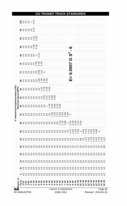
GO TRANSIT TRACK STANDARDS
TRACK STANDARDS Page 46 RC-0506-02TRK JUNE 2016 Revised: 2016-04-20
510
1520
2530
3540
4550
5560
6570
7580
8590
9510
00°
15'
1/2
1/2
1/2
1/2
1/2
1/2
1/2
1/2
1/2
1/2
1/2
1/2
1/2
1/2
1/2
1/2
1/2
1/2
1/2
1/2
0°30
'1/
21/
21/
21/
21/
21/
21/
21/
21/
21/
21/
21/
21/
21/
21/
21/
21/
21/
21/
21/
20°
45'
1/2
1/2
1/2
1/2
1/2
1/2
1/2
1/2
1/2
1/2
1/2
1/2
1/2
1/2
1/2
1/2
1/2
1/2
1/2
1/2
1° 0
0'1/
21/
21/
21/
21/
21/
21/
21/
21/
21/
21/
21/
21/
21/
21/
21/
21/
21/
21/
21
1° 3
0'1/
21/
21/
21/
21/
21/
21/
21/
21/
21/
21/
21/
21/
21/
21/
23/
41
5/8
2 1/
23
1/2
4 1/
22°
00'
1/2
1/2
1/2
1/2
1/2
1/2
1/2
1/2
1/2
1/2
1/2
1/2
1/2
7/8
1 7/
83
4 1/
85
3/8
2° 3
0'1/
21/
21/
21/
21/
21/
21/
21/
21/
21/
21/
21/
21
3/8
2 5/
83
7/8
5 1/
43°
00'
1/2
1/2
1/2
1/2
1/2
1/2
1/2
1/2
1/2
1/2
1/2
1 1/
22
7/8
4 1/
45
7/8
3° 3
0'1/
21/
21/
21/
21/
21/
21/
21/
21/
21/
21
3/8
2 7/
84
3/8
64°
00'
1/2
1/2
1/2
1/2
1/2
1/2
1/2
1/2
1/2
12
1/2
4 1/
85
7/8
4° 3
0'1/
21/
21/
21/
21/
21/
21/
21/
21/
21
7/8
3 1/
25
3/8
5° 0
0'1/
21/
21/
21/
21/
21/
21/
21/
21
1/8
2 3/
44
5/8
5° 3
0'1/
21/
21/
21/
21/
21/
21/
21/
21
3/4
3 5/
85
5/8
6° 0
0'1/
21/
21/
21/
21/
21/
21/
23/
42
1/2
4 1/
26°
30'
1/2
1/2
1/2
1/2
1/2
1/2
1/2
1 1/
43
1/4
5 3/
87°
00'
1/2
1/2
1/2
1/2
1/2
1/2
1/2
1 7/
83
7/8
7° 3
0'1/
21/
21/
21/
21/
21/
21/
22
3/8
4 5/
88°
00'
1/2
1/2
1/2
1/2
1/2
1/2
7/8
35
3/8
8° 3
0'1/
21/
21/
21/
21/
21/
21
1/4
3 1/
26
9° 0
0'1/
21/
21/
21/
21/
21/
21
3/4
4 1/
89°
30'
1/2
1/2
1/2
1/2
1/2
1/2
2 1/
84
5/8
10° 0
0'1/
21/
21/
21/
21/
21/
22
5/8
5 1/
410
° 30'
1/2
1/2
1/2
1/2
1/2
5/8
35
3/4
11° 0
0'1/
21/
21/
21/
21/
27/
83
3/8
11° 3
0'1/
21/
21/
21/
21/
21
1/4
3 7/
812
° 00'
1/2
1/2
1/2
1/2
1/2
1 1/
24
1/4
12° 3
0'1/
21/
21/
21/
21/
21
7/8
4 3/
413
° 00'
1/2
1/2
1/2
1/2
1/2
2 1/
45
1/8
13° 3
0'1/
21/
21/
21/
21/
22
1/2
5 5/
814
° 00'
1/2
1/2
1/2
1/2
1/2
2 7/
86
14° 3
0'1/
21/
21/
21/
21/
23
1/8
15° 0
0'1/
21/
21/
21/
25/
83
1/2
E= 0
.000
7 D
S2 - 6
6" Im
bala
nced
Sup
erle
leva
tion
(LRC
)De
gree
of
Curv
eBa
lanc
ed S
peed
(MPH
)

GO TRANSIT TRACK STANDARDS
TRACK STANDARDS Page 47 RC-0506-02TRK JUNE 2016 Revised: 2016-04-20
APPENDIX M – MINIMUM CONSTRUCTION STANDARDS
Cla
ss 1
, Yar
d
Per
App
endi
x N
– R
ail U
sage
Gui
delin
es o
r as
spe
cifie
d by
the
Rai
l Cor
ridor
s S
enio
r M
anag
er
of T
rack
and
Stru
ctur
es
Join
ted
or C
WR
100%
ties
pla
ted
per T
rack
Sta
ndar
d S
ectio
n 9.
1 an
d A
ppen
dix
Q –
Rec
omm
ende
d Ti
e P
late
U
sage
Impr
oved
Fai
r Typ
e A
ncho
rs o
r app
rove
d eq
uiva
lent
P
er T
rack
Sta
ndar
d S
ectio
n 9.
2
Ela
stic
Fas
tene
rs (P
andr
ol o
r app
rove
d eq
uiva
lent
) 6”
Cut
Spi
kes
26
40
2980
2980
As
per w
ritte
n di
rect
ion
from
the
Rai
l Cor
ridor
s S
enio
r Man
ager
of T
rack
and
Stru
ctur
es
2640
28
80 (
>7°
Cur
ves)
Cla
ss 2
and
3
CW
R
6 ho
le b
ars,
pun
ched
for a
ltern
atin
g ov
al-h
ead
bolts
pe
r CN
Sta
ndar
d P
lan
TS-1
202
26
40
3110
N/A
N/A
Cla
ss 4
and
Abo
ve
CW
R
Ela
stic
Fas
tene
rs (P
andr
ol)
6” C
ut S
pike
s
26
40
3110
N/A
N/A
Des
crip
tion
Rai
l Wei
ght
Rai
l (CW
R o
r Joi
nted
)
Tie
Plat
es
Rai
l Anc
hors
Fast
ener
s
Join
t Bar
s
Ties
per
Mile
C
oncr
ete
Har
dwoo
d G
rade
1
Har
dwoo
d G
rade
2
AC
ZA
Ste
el
(Use
M10
, M12
, H10
, H12
, as
dire
cted
by
Trac
k C
oE)
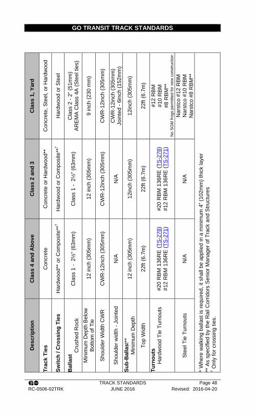
GO TRANSIT TRACK STANDARDS
TRACK STANDARDS Page 48 RC-0506-02TRK JUNE 2016 Revised: 2016-04-20
C
lass
1, Y
ard
Con
cret
e, S
teel
, or H
ardw
ood
Har
dwoo
d or
Ste
el
Cla
ss 2
- 2”
(51m
m)
AR
EM
A C
lass
4A
(Ste
el ti
es)
9 in
ch (2
30 m
m)
CW
R-1
2inc
h (3
05m
m)
CW
R-1
2inc
h (3
05m
m)
Join
ted
- 6in
ch (1
52m
m)
12in
ch (3
05m
m)
22ft
(6.7
m)
#12
RB
M
#10
RB
M
#8 R
BM
**
No
SGM
frog
s pe
rmitt
ed fo
r new
con
stru
ctio
n
Nar
stco
#12
RBM
N
arst
co #
10 R
BM
Nar
stco
#8
RBM
**
* W
here
wal
king
bal
last
is re
quire
d, it
sha
ll be
app
lied
in a
min
imum
4” (
102m
m) t
hick
laye
r **
As
spec
ified
by
the
Rai
l Cor
ridor
s S
enio
r Man
ager
of T
rack
and
Stru
ctur
es
† Onl
y fo
r cro
ssin
g tie
s.
Cla
ss 2
and
3
Con
cret
e or
Har
dwoo
d**
Har
dwoo
d or
Com
posi
te**
†
Cla
ss 1
- 2
½” (
63m
m)
12 in
ch (3
05m
m)
CW
R-1
2inc
h (3
05m
m)
N/A
12in
ch (3
05m
m)
22ft
(6.7
m)
#20
RB
M 1
36R
E (T
S-2
78)
#12
RB
M 1
36R
E (T
S-2
71)
N/A
Cla
ss 4
and
Abo
ve
Con
cret
e
Har
dwoo
d**
or C
ompo
site
**†
Cla
ss 1
- 2
½” (
63m
m)
12 in
ch (3
05m
m)
CW
R-1
2inc
h (3
05m
m)
N/A
12 in
ch (3
05m
m)
22ft
(6.7
m)
#20
RB
M 1
36R
E (T
S-2
78)
#12
RB
M 1
36R
E (T
S-2
71)
N/A
Des
crip
tion
Trac
k Ti
es
Switc
h / C
ross
ing
Ties
Bal
last
Cru
shed
Roc
k M
inim
um D
epth
Bel
ow
Bot
tom
of T
ie
Sho
ulde
r Wid
th C
WR
Sho
ulde
r wid
th -
Join
ted
Sub-
Bal
last
**
Min
imum
Dep
th
Top
Wid
th
Turn
outs
H
ardw
ood
Tie
Turn
outs
Ste
el T
ie T
urno
uts
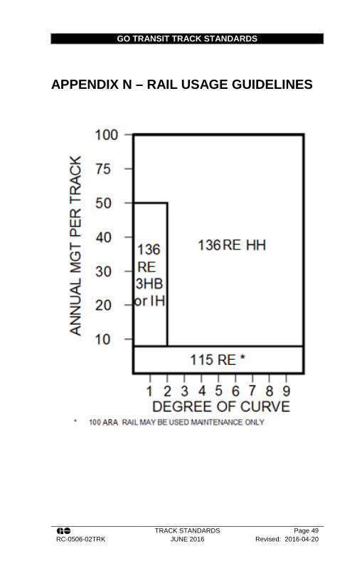
GO TRANSIT TRACK STANDARDS
TRACK STANDARDS Page 49 RC-0506-02TRK JUNE 2016 Revised: 2016-04-20
APPENDIX N – RAIL USAGE GUIDELINES

GO TRANSIT TRACK STANDARDS
TRACK STANDARDS Page 50 RC-0506-02TRK JUNE 2016 Revised: 2016-04-20
APPENDIX O – STANDARD RAIL HEAD PROFILES
100ARA-A, 115RE, 132RE and 136RE
This section is under development

GO TRANSIT TRACK STANDARDS
TRACK STANDARDS Page 51 RC-0506-02TRK JUNE 2016 Revised: 2016-04-20
APPENDIX P – SPIKING PATTERNS
D
egre
e of
Cur
ve
>8º
X X X
Turn
out
spik
ing
patte
rn D
will
be
appl
ied
to t
urno
uts
per F
igur
e 11
.
>4º -
6º
X X
>2º -
4º
X X X
0º -
2º
X X X X
MG
T pe
r Y
ear
Oth
er th
an
Mai
n Tr
ack
0-20
0-20
>20
0-20
>20
>20
Spi
king
Pat
tern
No.
A B C
D
*When MSR Plates are used, ALL holes shall be fully lagged and spiked.

GO TRANSIT TRACK STANDARDS
TRACK STANDARDS Page 52 RC-0506-02TRK JUNE 2016 Revised: 2016-04-20
APPENDIX Q – RECOMMENDED TIE PLATE USAGE
5½”
(140
mm
) Rai
l Bas
e
14”
(356
mm
) DS
plat
e w
ith 1
:40
Can
ted
Rai
l Sea
t,
MSR
16”
(406
mm
) and
18”
(457
mm
) Pla
tes
All
(E
xist
ing
11” D
S Ti
e pl
ates
sha
ll be
repl
aced
thro
ugh
rout
ine
mai
nten
ance
)
All
6” (1
52m
m) R
ail B
ase
MSR
16”
(406
mm
) Pl
ate
(Pan
drol
Clip
s)
Deg
ree
of C
urve
N/A
> 6º
> 6º
> 4º
>2º
16”
(406
mm
) DS
Plat
e
> 6º
>4º -
6º
>4º -
6º
>2º -
4º
0º -
2º
14”
(356
mm
) DS
Pla
te w
ith 1
:40
Can
t
0º -
6º
0º -
4º
0º -
4º
0º -
2º
N/A
Cla
ss o
f Tra
ck
Yar
d
1 - 5
1 - 5
1 - 5
1 - 2
3 - 5
3 - 5
Ann
ual
Tonn
age
(MG
T)
All
All ≤5
>5 -
20
>20
- 40
>40

GO TRANSIT TRACK STANDARDS
TRACK STANDARDS Page 53 RC-0506-02TRK JUNE 2016 Revised: 2016-04-20
APPENDIX R – TYPICAL BALLAST PROFILES
See CN Standard Plan TS-2205 for details.
For use with Steel Ties see Narstco Steel Tie and Turnout Set Assembly Instructions Manual

GO TRANSIT TRACK STANDARDS
TRACK STANDARDS Page 54 RC-0506-02TRK JUNE 2016 Revised: 2016-04-20
APPENDIX S – TYPICAL TRACK CROSS SECTIONS (METRIC)
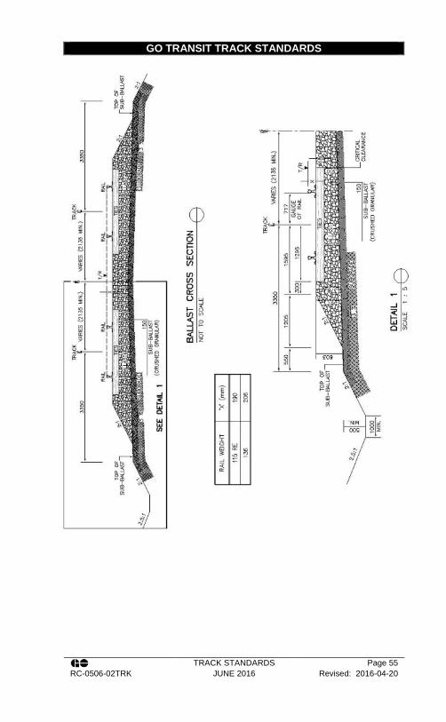
GO TRANSIT TRACK STANDARDS
TRACK STANDARDS Page 55 RC-0506-02TRK JUNE 2016 Revised: 2016-04-20

GO TRANSIT TRACK STANDARDS
TRACK STANDARDS Page 56 RC-0506-02TRK JUNE 2016 Revised: 2016-04-20
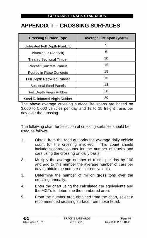
GO TRANSIT TRACK STANDARDS
TRACK STANDARDS Page 57 RC-0506-02TRK JUNE 2016 Revised: 2016-04-20
APPENDIX T – CROSSING SURFACES
Crossing Surface Type Average Life Span (years)
Untreated Full Depth Planking 5
Bituminous (Asphalt) 6
Treated Sectional Timber 10
Precast Concrete Panels 15
Poured in Place Concrete 15
Full Depth Recycled Rubber 15
Sectional Steel Panels 18
Full Depth Virgin Rubber 20
Steel Reinforced Virgin Rubber 20
The above average crossing surface life spans are based on 3,000 to 5,000 vehicles per day and 12 to 15 freight trains per day over the crossing.
The following chart for selection of crossing surfaces should be used as follows: 1. Obtain from the road authority the average daily vehicle
count for the crossing involved. This count should include separate counts for the number of trucks and cars using the crossing on daily basis.
2. Multiply the average number of trucks per day by 100 and add to this number the average number of cars per day to obtain the number of car equivalents.
3. Determine the number of million gross tons over the crossing annually.
4. Enter the chart using the calculated car equivalents and the MGTs to determine the numbered area.
5. From the number area obtained from the chart, select a recommended crossing surface from those listed.

GO TRANSIT TRACK STANDARDS
TRACK STANDARDS Page 58 RC-0506-02TRK JUNE 2016 Revised: 2016-04-20
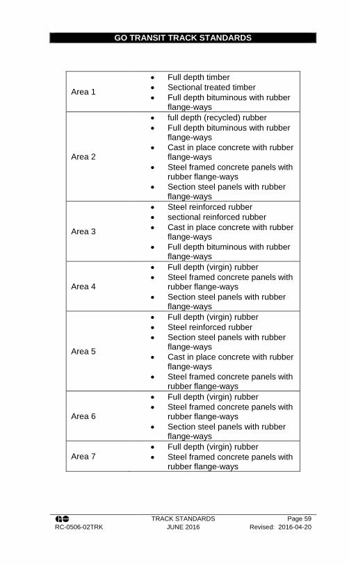
GO TRANSIT TRACK STANDARDS
TRACK STANDARDS Page 59 RC-0506-02TRK JUNE 2016 Revised: 2016-04-20
Area 1
• Full depth timber • Sectional treated timber • Full depth bituminous with rubber
flange-ways
Area 2
• full depth (recycled) rubber • Full depth bituminous with rubber
flange-ways • Cast in place concrete with rubber
flange-ways • Steel framed concrete panels with
rubber flange-ways • Section steel panels with rubber
flange-ways
Area 3
• Steel reinforced rubber • sectional reinforced rubber • Cast in place concrete with rubber
flange-ways • Full depth bituminous with rubber
flange-ways
Area 4
• Full depth (virgin) rubber • Steel framed concrete panels with
rubber flange-ways • Section steel panels with rubber
flange-ways
Area 5
• Full depth (virgin) rubber • Steel reinforced rubber • Section steel panels with rubber
flange-ways • Cast in place concrete with rubber
flange-ways • Steel framed concrete panels with
rubber flange-ways
Area 6
• Full depth (virgin) rubber • Steel framed concrete panels with
rubber flange-ways • Section steel panels with rubber
flange-ways
Area 7 • Full depth (virgin) rubber • Steel framed concrete panels with
rubber flange-ways
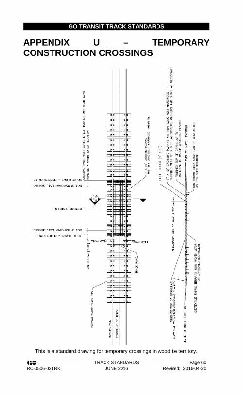
GO TRANSIT TRACK STANDARDS
TRACK STANDARDS Page 60 RC-0506-02TRK JUNE 2016 Revised: 2016-04-20
APPENDIX U – TEMPORARY CONSTRUCTION CROSSINGS
This is a standard drawing for temporary crossings in wood tie territory.

GO TRANSIT TRACK STANDARDS
TRACK STANDARDS Page 61 RC-0506-02TRK JUNE 2016 Revised: 2016-04-20
APPENDIX V – GO TRANSIT HEAVY RAIL CLEARANCE ENVELOPES
Figure 25. All Structures Over or Beside Railway Tracks

GO TRANSIT TRACK STANDARDS
TRACK STANDARDS Page 62 RC-0506-02TRK JUNE 2016 Revised: 2016-04-20
Figure 26. All Railway Bridges, Snow-sheds and Overhead Timber Bridges (non-electrified)

GO TRANSIT TRACK STANDARDS
TRACK STANDARDS Page 63 RC-0506-02TRK JUNE 2016 Revised: 2016-04-20
Figure 27. All Railway Tunnels (non-electrified)

GO TRANSIT TRACK STANDARDS
TRACK STANDARDS Page 64 RC-0506-02TRK JUNE 2016 Revised: 2016-04-20
Figure 28. Industrial Sidings (non-electrified)

GO TRANSIT TRACK STANDARDS
TRACK STANDARDS Page 65 RC-0506-02TRK JUNE 2016 Revised: 2016-04-20
Union Station Clearance Envelope
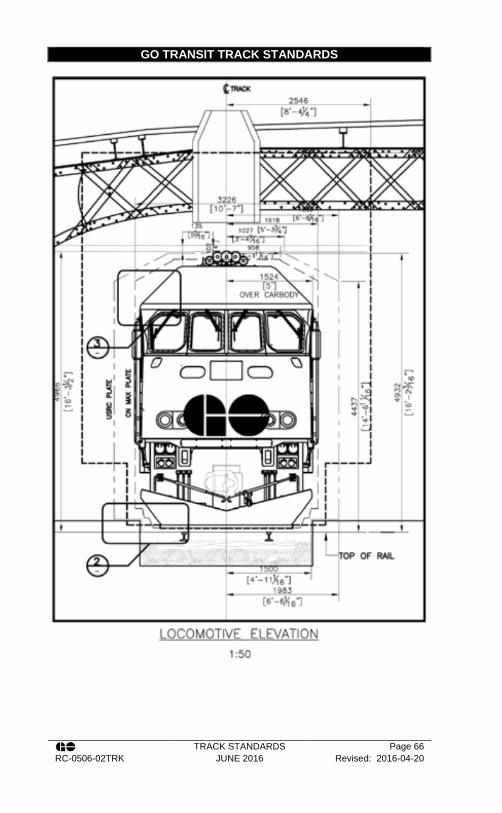
GO TRANSIT TRACK STANDARDS
TRACK STANDARDS Page 66 RC-0506-02TRK JUNE 2016 Revised: 2016-04-20

GO TRANSIT TRACK STANDARDS
TRACK STANDARDS Page 67 RC-0506-02TRK JUNE 2016 Revised: 2016-04-20
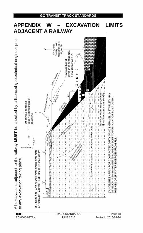
GO TRANSIT TRACK STANDARDS
TRACK STANDARDS Page 68 RC-0506-02TRK JUNE 2016 Revised: 2016-04-20
APPENDIX W – EXCAVATION LIMITS ADJACENT A RAILWAY
All e
xcav
atio
ns a
djac
ent t
o th
e ra
ilway
MU
ST b
e ch
ecke
d by
a li
cenc
ed g
eote
chni
cal e
ngin
eer
prio
r to
any
exc
avat
ion
taki
ng p
lace
.
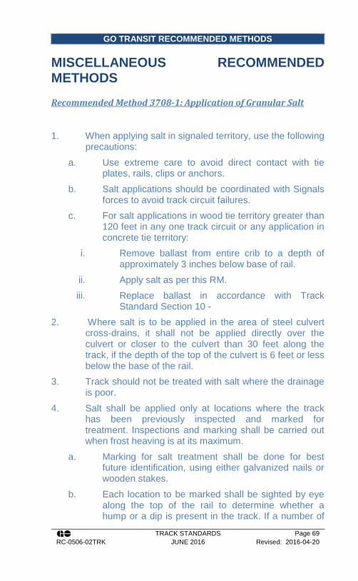
GO TRANSIT RECOMMENDED METHODS
TRACK STANDARDS Page 69 RC-0506-02TRK JUNE 2016 Revised: 2016-04-20
MISCELLANEOUS RECOMMENDED METHODS
Recommended Method 3708-1: Application of Granular Salt
1. When applying salt in signaled territory, use the following precautions:
a. Use extreme care to avoid direct contact with tie plates, rails, clips or anchors.
b. Salt applications should be coordinated with Signals forces to avoid track circuit failures.
c. For salt applications in wood tie territory greater than 120 feet in any one track circuit or any application in concrete tie territory:
i. Remove ballast from entire crib to a depth of approximately 3 inches below base of rail.
ii. Apply salt as per this RM. iii. Replace ballast in accordance with Track
Standard Section 10 - 2. Where salt is to be applied in the area of steel culvert
cross-drains, it shall not be applied directly over the culvert or closer to the culvert than 30 feet along the track, if the depth of the top of the culvert is 6 feet or less below the base of the rail.
3. Track should not be treated with salt where the drainage is poor.
4. Salt shall be applied only at locations where the track has been previously inspected and marked for treatment. Inspections and marking shall be carried out when frost heaving is at its maximum.
a. Marking for salt treatment shall be done for best future identification, using either galvanized nails or wooden stakes.
b. Each location to be marked shall be sighted by eye along the top of the rail to determine whether a hump or a dip is present in the track. If a number of

GO TRANSIT RECOMMENDED METHODS
TRACK STANDARDS Page 70 RC-0506-02TRK JUNE 2016 Revised: 2016-04-20
humps or dips occur together, the marking should be done as for a continuous hump or dip from one end of the area to the other
c. Humps shall be marked at the peak of the hump. d. Dips shall be marked 12 cribs from the lowest point
in both directions. e. Location and site description are to be recorded.
5. The salt shall be applied at such a time that it will receive at least 3 inches and not more than 6 inches of rainfall after application and before the arrival of freezing temperatures. The Rail Corridors Senior Manager of Track and Structures should be consulted for the dates of application.
6. Before the salt is distributed along the right-of-way, an inspection shall be made during which time:
a. Any reference marks, which have been obliterated or displaced, shall be replaced.
b. The number of bags of salt required at each location shall be suitably marked on the track for reference when the salt is being unloaded. The number of 50-pound bags required for any location is equal to the total number of cribs to be treated divided by two, minus three. Distribution of salt along the right-of-way prior to application shall be as close to the time of application as possible to avoid deterioration.
7. Care must be exercised to insure that the correct amount of salt is applied. Salt shall be applied at each marked location as follows:
a. 12-1/2 pounds of salt shall be placed in each of the six cribs within each end of the marked location.
b. The remaining cribs within the marked location shall have 25 pounds of salt applied in each crib.
c. The salt shall be spread evenly on top of the ballast over the full length of the crib, but not beyond the ends of the ties. The ballast shall not be excavated but the salt may be worked into the top voids of the ballast to avoid caking.

GO TRANSIT RECOMMENDED METHODS
TRACK STANDARDS Page 71 RC-0506-02TRK JUNE 2016 Revised: 2016-04-20
8. The date of application of the salt shall be recorded along with the total amount of salt applied. The Track Supervisor will maintain all records of salt applications.
9. Each salt application shall be made according to marks for the first application unless a ballast lift or other track work is believed to have influenced heaving. In this case no salt shall be applied until the track heaves and the new distribution of heaving can be marked.
10. Salt used for treatment shall be either Coarse Grade or Fine Grade Crushed salt (sodium chloride). In dry areas, Fine Grade quality is preferable. Salt should be supplied in 50-pound bags provided with a moisture barrier to prevent caking.
11. Salt as applied herein is normally effective for two winters in reducing track heaving. This shall be considered in planning the dates for salt application.

GO TRANSIT RECOMMENDED METHODS
TRACK STANDARDS Page 72 RC-0506-02TRK JUNE 2016 Revised: 2016-04-20
Recommended Method 1802-0: Covering the Acceptance of New Material and Conducting an In-Service Test of New Material
1. Before a new material is considered for an in-service test the manufacturer of the new material shall provide the following documentation for consideration:
a. The material meets or exceeds the standards set out by AREMA including that the material was subjected to the testing requirements and procedure(s) described by AREMA;
b. The Manufacturer shall submit in triplicate documentation from a certified testing laboratory that the material meets or exceeds the requirements stated in part a above; and,
c. The Manufacturer shall submit in triplicate certified documentation from a field testing facility such as TTCI or other approved testing facility, that the material has been subjected to railroad loading, clearly stating the gross tonnage imposed and duration in months, and certifying in writing that the material may be proceed to a field in-service test, complete with any limitations.
2. No new or modified materials may be considered for use as a standard without also being subjected to a service test unless authorized by the Rail Corridors Senior Manager of Track and Structures
3. Service tests requests may originate from the Metrolinx Track Centre of Excellence or GO Transit Rail Corridors Track Office
4. The Rail Corridors Senior Manager of Track and Structures shall oversee all service tests
5. When a test is being considered, documentation of such should be forwarded to both the Rail Corridors Senior Manager of Track and Structures and the Track Centre of Excellence Senior Manager of Track. The Rail Corridors Manager of Track and Track Evaluation Officer will also be notified.
6. The location of the test must be carefully chosen in order to best suit the requirements of the test. The site should

GO TRANSIT RECOMMENDED METHODS
TRACK STANDARDS Page 73 RC-0506-02TRK JUNE 2016 Revised: 2016-04-20
allow fair comparison of the new material to existing standards as well as permit easy access and monitoring where practical.
7. A test file will be created and performed by the Track Standards Committee and must include:
a. The purpose and description of test (including contact information for the manufacturer)
b. Estimated costs c. Potential Benefits d. Location of Test e. Approximate duration; and f. Direct supervision
8. Where applicable the following will also be kept in the test file and forwarded to the Track Standards Committee:
a. Laboratory testing b. Specification c. Installation instructions
9. A test protocol should be jointly created by the Track Standards Committee and the manufacturer to establish what measures will be used to evaluate the product, what targets will signify a successful test, and the frequency at which measurement will be taken.
10. The Rail Corridors Senior Manager of Track and Structure will assign a responsible person to:
a. Ensure proper installation b. Ensure proper maintenance c. Arrange for the collection of test data on a timely
basis; and d. Forward all test data to the Track Standards
Committee 11. Tests should not be disturbed, except in emergency,
unless authorized by the Rail Corridors Senior Manager of Track and Structures, or if a safety concern is found.

GO TRANSIT RECOMMENDED METHODS
TRACK STANDARDS Page 74 RC-0506-02TRK JUNE 2016 Revised: 2016-04-20
12. The Track Centre of Excellence Senior Manager will prepare and issue progress and final reports on all service tests.
13. Service tests will remain active until terminated by the Track Standards Committee.
GO TRANSIT TRACK STANDARDS
TRACK STANDARDS Page 75 RC-0506-02TRK JUNE 2016 Revised: 2016-04-20
CONVERSION TABLES FOR UNITS OF MEASURE

GO TRANSIT TRACK STANDARDS
TRACK STANDARDS Page 76 RC-0506-02TRK JUNE 2016 Revised: 2016-04-20
DESIGNATED AUTHORITY
1. Areas of responsibility where the Rail Corridors Senior Manager of Track and Structures has delegated authority are located in Table 46.
2. Table 46 indicates only the sections where authority has been delegated. For all other inquiries, the Rail Corridors Senior Manager of Track and Structures is the designated authority.
Table 46 Table of Designated Authority
Position Office Delegated Authority
Manager of Track GO Rail Corridors • Crossing Surfaces • Construction Material
Requirements Track Evaluation Officer
GO Rail Corridors • Rail Breaks / Defects
Track and Structures Standards Officer
GO Rail Corridors N/A
Track Specialist GO Rail Corridors • Track Inspection and Quality Control
Track Protection Officer
GO Rail Corridors N/A
Contract Compliance Officer
GO Rail Corridors N/A
Senior Manager of Track
Metrolinx Track COE N/A
Manager of Track Metrolinx Track COE N/A Manager of Track Standards
Metrolinx Track COE • Review and recommend new / changes to standards, and materials
Project Manager Metrolinx Track COE N/A

GO TRANSIT TRACK STANDARDS
TRACK STANDARDS Page 77 RC-0506-02TRK JUNE 2016 Revised: 2016-04-20
NOTES
________________________________________________________________________________________________________________________________________________________________________________________________________________________________________________________________________________________________________________________________________________________________________________________________________________________________________________________________________________________________________________________________________________________________________________________________________________________________________________________________________________________________________________________________________________________________________________________________________________________________________________________________________________________________________________________________________________________________________________________________________________________________________________________________________________________________________________________________________________________________________________________________________________________________________________________________________________________________________________________________________________________________________________________________________________________________________________________________________________________________________________________________________________________________________________________________________________________________________________________________________________________________________________________________________________________________________________________________________________________________________________________________________________________________________________________________________________________________________________________________________________________________________________________________________________________________________________________

GO TRANSIT TRACK STANDARDS
TRACK STANDARDS Page 78 RC-0506-02TRK JUNE 2016 Revised: 2016-04-20
_________________________________________________________________________________________________________________________________________________________________________________________________________________________________________________________________________________________________________________________________________________________________________________________________________________________________________________________________________________________________________________________________________________________________________________________________________________________________________________________________________________________________________________________________________________________________________________________________________________________________________________________________________________________________________________________________________________________________________________________________________________________________________________________________________________________________________________________________________________________________________________________________________________________________________________________________________________________________________________________________________________________________________________________________________________________________________________________________________________________________________________________________________________________________________________________________________________________________________________________________________________________________________________________________________________________________________________________________________________________________________________________________________________________________________________________________________________________________________________________________________________________________________________________________________________________________________________________________________________________________________________________________________________________________________________________________________________

GO TRANSIT TRACK STANDARDS
TRACK STANDARDS Page 79 RC-0506-02TRK JUNE 2016 Revised: 2016-04-20
_________________________________________________________________________________________________________________________________________________________________________________________________________________________________________________________________________________________________________________________________________________________________________________________________________________________________________________________________________________________________________________________________________________________________________________________________________________________________________________________________________________________________________________________________________________________________________________________________________________________________________________________________________________________________________________________________________________________________________________________________________________________________________________________________________________________________________________________________________________________________________________________________________________________________________________________________________________________________________________________________________________________________________________________________________________________________________________________________________________________________________________________________________________________________________________________________________________________________________________________________________________________________________________________________________________________________________________________________________________________________________________________________________________________________________________________________________________________________________________________________________________________________________________________________________________________________________________________________________________________________________________________________________________________________________________________________________________

GO TRANSIT TRACK STANDARDS
TRACK STANDARDS Page 80 RC-0506-02TRK JUNE 2016 Revised: 2016-04-20
_________________________________________________________________________________________________________________________________________________________________________________________________________________________________________________________________________________________________________________________________________________________________________________________________________________________________________________________________________________________________________________________________________________________________________________________________________________________________________________________________________________________________________________________________________________________________________________________________________________________________________________________________________________________________________________________________________________________________________________________________________________________________________________________________________________________________________________________________________________________________________________________________________________________________________________________________________________________________________________________________________________________________________________________________________________________________________________________________________________________________________________________________________________________________________________________________________________________________________________________________________________________________________________________________________________________________________________________________________________________________________________________________________________________________________________________________________________________________________________________________________________________________________________________________________________________________________________________________________________________________________________________________________________________________________________________________________________

GO TRANSIT TRACK STANDARDS
TRACK STANDARDS Page 81 RC-0506-02TRK JUNE 2016 Revised: 2016-04-20
_________________________________________________________________________________________________________________________________________________________________________________________________________________________________________________________________________________________________________________________________________________________________________________________________________________________________________________________________________________________________________________________________________________________________________________________________________________________________________________________________________________________________________________________________________________________________________________________________________________________________________________________________________________________________________________________________________________________________________________________________________________________________________________________________________________________________________________________________________________________________________________________________________________________________________________________________________________________________________________________________________________________________________________________________________________________________________________________________________________________________________________________________________________________________________________________________________________________________________________________________________________________________________________________________________________________________________________________________________________________________________________________________________________________________________________________________________________________________________________________________________________________________________________________________________________________________________________________________________________________________________________________________________________________________________________________________________________

GO TRANSIT TRACK STANDARDS
TRACK STANDARDS Page 82 RC-0506-02TRK JUNE 2016 Revised: 2016-04-20
_________________________________________________________________________________________________________________________________________________________________________________________________________________________________________________________________________________________________________________________________________________________________________________________________________________________________________________________________________________________________________________________________________________________________________________________________________________________________________________________________________________________________________________________________________________________________________________________________________________________________________________________________________________________________________________________________________________________________________________________________________________________________________________________________________________________________________________________________________________________________________________________________________________________________________________________________________________________________________________________________________________________________________________________________________________________________________________________________________________________________________________________________________________________________________________________________________________________________________________________________________________________________________________________________________________________________________________________________________________________________________________________________________________________________________________________________________________________________________________________________________________________________________________________________________________________________________________________________________________________________________________________________________________________________________________________________________________

GO TRANSIT TRACK STANDARDS
TRACK STANDARDS Page 83 RC-0506-02TRK JUNE 2016 Revised: 2016-04-20
_________________________________________________________________________________________________________________________________________________________________________________________________________________________________________________________________________________________________________________________________________________________________________________________________________________________________________________________________________________________________________________________________________________________________________________________________________________________________________________________________________________________________________________________________________________________________________________________________________________________________________________________________________________________________________________________________________________________________________________________________________________________________________________________________________________________________________________________________________________________________________________________________________________________________________________________________________________________________________________________________________________________________________________________________________________________________________________________________________________________________________________________________________________________________________________________________________________________________________________________________________________________________________________________________________________________________________________________________________________________________________________________________________________________________________________________________________________________________________________________________________________________________________________________________________________________________________________________________________________________________________________________________________________________________________________________________________________

GO TRANSIT TRACK STANDARDS
TRACK STANDARDS Page 84 RC-0506-02TRK JUNE 2016 Revised: 2016-04-20
_________________________________________________________________________________________________________________________________________________________________________________________________________________________________________________________________________________________________________________________________________________________________________________________________________________________________________________________________________________________________________________________________________________________________________________________________________________________________________________________________________________________________________________________________________________________________________________________________________________________________________________________________________________________________________________________________________________________________________________________________________________________________________________________________________________________________________________________________________________________________________________________________________________________________________________________________________________________________________________________________________________________________________________________________________________________________________________________________________________________________________________________________________________________________________________________________________________________________________________________________________________________________________________________________________________________________________________________________________________________________________________________________________________________________________________________________________________________________________________________________________________________________________________________________________________________________________________________________________________________________________________________________________________________________________________________________________________

GO TRANSIT TRACK STANDARDS
TRACK STANDARDS Page 85 RC-0506-02TRK JUNE 2016 Revised: 2016-04-20
_________________________________________________________________________________________________________________________________________________________________________________________________________________________________________________________________________________________________________________________________________________________________________________________________________________________________________________________________________________________________________________________________________________________________________________________________________________________________________________________________________________________________________________________________________________________________________________________________________________________________________________________________________________________________________________________________________________________________________________________________________________________________________________________________________________________________________________________________________________________________________________________________________________________________________________________________________________________________________________________________________________________________________________________________________________________________________________________________________________________________________________________________________________________________________________________________________________________________________________________________________________________________________________________________________________________________________________________________________________________________________________________________________________________________________________________________________________________________________________________________________________________________________________________________________________________________________________________________________________________________________________________________________________________________________________________________________________
GO TRANSIT TRACK STANDARDS
TRACK STANDARDS Page 86 RC-0506-02TRK JUNE 2016 Revised: 2016-04-20
_____________________________________________________________________________________________________________________________________________________________________________________________________________________________________________________________________________________________________________________________________________________________________________________________________________________________________________________________________________________________________________________________________________________________________________________________________________________________________________________________________________________________________________________________________________________________________________________________________________________________________________________________________________________________________________________________________________________________________________________________________________________________________________________________________________________________________________________________________________________________________________________________________________________________________________________________________________________________________________________________________________________________________________________________________________________________________________________________________________________________________________________________________________________________________________________________________________________________________________________________________________________________________________________________________________________________________________________________________________________________________________________________________________________________________________________________________________________________________________________________________________________________________________________________________________________________________________________________________________________________________________________________________________________________