owner’s manual orchestra pit filler - wenger corp orchestra pit filler owners.pdfowner’s manual...
TRANSCRIPT

Owner’s ManualOrchestra Pit Filler
©Wenger Corporation 2013 Printed in USA 10/13 Patent Pending Part Number 182A499-02
Wenger Corporation, 555 Park Drive, P.O. Box 448, Owatonna, Minnesota 55060-0448Questions? Call.....USA: (800) 733-0393 • International (call collect): (507) 455-4100 • www.wengercorp.com
CONTENTSSafety Precautions . . . . . . . . . . . . . . . . . . . . . . . . . . . . . . . . . . . . . . . . . . . . . . . . . . . . . . . . . . . . . . . . . . . . . . . . .2
Pit Filler Stability . . . . . . . . . . . . . . . . . . . . . . . . . . . . . . . . . . . . . . . . . . . . . . . . . . . . . . . . . . . . . . . . . . . . . . . . .2Transport and Storage Carts . . . . . . . . . . . . . . . . . . . . . . . . . . . . . . . . . . . . . . . . . . . . . . . . . . . . . . . . . . . . . . . .2
Setting Up for the First Time . . . . . . . . . . . . . . . . . . . . . . . . . . . . . . . . . . . . . . . . . . . . . . . . . . . . . . . . . . . . . . . . . .2Warranty . . . . . . . . . . . . . . . . . . . . . . . . . . . . . . . . . . . . . . . . . . . . . . . . . . . . . . . . . . . . . . . . . . . . . . . . . . . . . . . . .3Pit Filler Installation Procedure . . . . . . . . . . . . . . . . . . . . . . . . . . . . . . . . . . . . . . . . . . . . . . . . . . . . . . . . . . . . . . . .4
Review Material . . . . . . . . . . . . . . . . . . . . . . . . . . . . . . . . . . . . . . . . . . . . . . . . . . . . . . . . . . . . . . . . . . . . . . . . . .4Install First Main Beam . . . . . . . . . . . . . . . . . . . . . . . . . . . . . . . . . . . . . . . . . . . . . . . . . . . . . . . . . . . . . . . . . . . .4Assemble First Bay . . . . . . . . . . . . . . . . . . . . . . . . . . . . . . . . . . . . . . . . . . . . . . . . . . . . . . . . . . . . . . . . . . . . . . .7Continue Adding Bays . . . . . . . . . . . . . . . . . . . . . . . . . . . . . . . . . . . . . . . . . . . . . . . . . . . . . . . . . . . . . . . . . . . . .9
Pit Filler Disassembly Procedure . . . . . . . . . . . . . . . . . . . . . . . . . . . . . . . . . . . . . . . . . . . . . . . . . . . . . . . . . . . . . .10Disassemble Accessories . . . . . . . . . . . . . . . . . . . . . . . . . . . . . . . . . . . . . . . . . . . . . . . . . . . . . . . . . . . . . . . . . .10Disassemble Decks . . . . . . . . . . . . . . . . . . . . . . . . . . . . . . . . . . . . . . . . . . . . . . . . . . . . . . . . . . . . . . . . . . . . . . .10Loosen Main Beam Anchors . . . . . . . . . . . . . . . . . . . . . . . . . . . . . . . . . . . . . . . . . . . . . . . . . . . . . . . . . . . . . . . .11Disconnect Cross Beam Diagonal from Columns . . . . . . . . . . . . . . . . . . . . . . . . . . . . . . . . . . . . . . . . . . . . . . . .11Disassemble the Understructure . . . . . . . . . . . . . . . . . . . . . . . . . . . . . . . . . . . . . . . . . . . . . . . . . . . . . . . . . . . . .12
Transport and Store Pit Filler . . . . . . . . . . . . . . . . . . . . . . . . . . . . . . . . . . . . . . . . . . . . . . . . . . . . . . . . . . . . . . . . . .14Deck Transport and Storage Cart . . . . . . . . . . . . . . . . . . . . . . . . . . . . . . . . . . . . . . . . . . . . . . . . . . . . . . . . . . . .14Column and Beam Storage and Transport Cart . . . . . . . . . . . . . . . . . . . . . . . . . . . . . . . . . . . . . . . . . . . . . . . . .14
Maintenance . . . . . . . . . . . . . . . . . . . . . . . . . . . . . . . . . . . . . . . . . . . . . . . . . . . . . . . . . . . . . . . . . . . . . . . . . . . . . .15Decks . . . . . . . . . . . . . . . . . . . . . . . . . . . . . . . . . . . . . . . . . . . . . . . . . . . . . . . . . . . . . . . . . . . . . . . . . . . . . . . . . .15Drapery Closures . . . . . . . . . . . . . . . . . . . . . . . . . . . . . . . . . . . . . . . . . . . . . . . . . . . . . . . . . . . . . . . . . . . . . . . . .15Other Preventive Maintenance . . . . . . . . . . . . . . . . . . . . . . . . . . . . . . . . . . . . . . . . . . . . . . . . . . . . . . . . . . . . . .15
Replacement Parts List . . . . . . . . . . . . . . . . . . . . . . . . . . . . . . . . . . . . . . . . . . . . . . . . . . . . . . . . . . . . . . . . . . . . . .16Deck . . . . . . . . . . . . . . . . . . . . . . . . . . . . . . . . . . . . . . . . . . . . . . . . . . . . . . . . . . . . . . . . . . . . . . . . . . . . . . . . . .16Column Bracket . . . . . . . . . . . . . . . . . . . . . . . . . . . . . . . . . . . . . . . . . . . . . . . . . . . . . . . . . . . . . . . . . . . . . . . . . .17Beam Brace Bracket . . . . . . . . . . . . . . . . . . . . . . . . . . . . . . . . . . . . . . . . . . . . . . . . . . . . . . . . . . . . . . . . . . . . . .18Column Foot . . . . . . . . . . . . . . . . . . . . . . . . . . . . . . . . . . . . . . . . . . . . . . . . . . . . . . . . . . . . . . . . . . . . . . . . . . . .19Column Brace Bracket . . . . . . . . . . . . . . . . . . . . . . . . . . . . . . . . . . . . . . . . . . . . . . . . . . . . . . . . . . . . . . . . . . . .19Cross Beam . . . . . . . . . . . . . . . . . . . . . . . . . . . . . . . . . . . . . . . . . . . . . . . . . . . . . . . . . . . . . . . . . . . . . . . . . . . . .20Cross Beam Socket . . . . . . . . . . . . . . . . . . . . . . . . . . . . . . . . . . . . . . . . . . . . . . . . . . . . . . . . . . . . . . . . . . . . . . .20Anchor Bracket, Stage Edge . . . . . . . . . . . . . . . . . . . . . . . . . . . . . . . . . . . . . . . . . . . . . . . . . . . . . . . . . . . . . . . .21Anchor Bracket, Audience Wall . . . . . . . . . . . . . . . . . . . . . . . . . . . . . . . . . . . . . . . . . . . . . . . . . . . . . . . . . . . . . .22Optional Cart Assembly . . . . . . . . . . . . . . . . . . . . . . . . . . . . . . . . . . . . . . . . . . . . . . . . . . . . . . . . . . . . . . . . . . . .23
Note: Please read and understand the Orchestra Pit Filler Owner’s Manual before starting theassembly. Familiarize yourself with the Pit Filler features and installation instructions.
Remove all items from the shipping containers and sort the components by size, length, etc.Refer to the illustrations on the following pages. If you need additional information about yourOrchestra Pit Filler, write or telephone Wenger Corporation at the number below.

Throughout this manual you will find CAUTIONSand WARNINGS which are defined as follows.• WARNING means that failure to follow the
instruction may result in serious injury ordeath.
• CAUTION means that failure to follow theinstruction may result in serious injury or damage to the pit filler.
SETUP• Make sure that anyone who helps set up the
Pit Filler is familiar with this manual.• Many steps require that two persons work
together in the setup.
PIT FILLER STABILITY• All Pit Filler Main Beams and Cross Beams
must be connected together using the methods described in this manual.
• The assembly must comply with the instructions contained in the Owner’s LayoutDrawing. For additional copies of the Owner’sLayout Drawing, contact Wenger CorporationCustomer Service at 1-800-887-7145
TRANSPORT AND STORAGE CARTS• Before loading pit filler components onto a
cart, always lock the casters on the cart.• Always secure the decks to the cart after
loading to prevent the Decks from falling.
2
SETTING UP FOR THE FIRST TIME1 Remove all parts from their shipping cartons (refer to the packing list enclosed with the shipment).
Save all packaging materials until the orchestra pit filler has been set up and assembled for the firsttime.
2. Sort all orchestra pit filler items by size, length, etc.
3. If the orchestra pit filler is to be stored before the initial set up and assembly, go to the TRANSPORTAND STORE PIT FILLER section.
4. If the Orchestra Pit Filler is to be set up immediately, go to Installation Procedure section.
NOTE: Read and understand this entire manual before starting the assembly.
SAFETY PRECAUTIONS
! WARNINGTo avoid injury, twopersons mustalways lift the beamassembly upward.
! WARNINGComponents mustbe connected asspecified in thismanual.
! CAUTIONAlways lock thecasters when load-ing and unloadingthe Cart.

WARRANTYWenger Orchestra Pit Fillers are guaranteed free of defects in materials and workmanship for five full years.
Our guarantee assures you of either a full refund or repair or replacement of the defective materials or workmanship without charge, at the discretion of our Customer Service Department. Just call a Customer Service Representative at 1-800-887-7145 and state the reason you are dissatisfied. If a product return is necessary, your representative will issue a return authorization. This is your sole remedy for breach of this warranty.
Should you have a question or problem with any Wenger product, don’t hesitate to call, even if the product is past warranty. It’s important to us that all our customers be satisfied.
This is the sole warranty made by Wenger. Wenger disclaims all other warranties, including the warranties of merchantability and fitness for a particular purpose, as well as all liability for incidental, consequential, special, and indirect damage. Wenger liability for direct damages shall be limited to the amount you paid for the product involved. Wenger reserves the right to make product changes without obligation to incorporate such changes into products previously sold.
Some states do not allow the exclusion or limitation of damages or warranties, so the above may notapply to you. This warranty gives you specific legal rights. You may also have other rights which varyfrom state to state.
3

4
PIT FILLER INSTALLATION PROCEDURE
REVIEW MATERIAL1. Review the owner’s packet that contains a layout drawing with instructions relating to the
orchestra pit filler installation.
Note: The numbering scheme on the layout drawing is letters for support structures and numbers for deck components.
INSTALL FIRST MAIN BEAM1. Each end of the Main Beam has a letter designation beginning with the letter A. Refer to the
layout drawing to identify which Beam and Column to assemble first and where in the pit theassembly starts.
2. Attach two columns to the first main beam by first matching the letters on the Columns to the letters on the Main Beam, A to A, B to B, and so on. Then, insert a Snap Lock Pin through thehole in each Column and Column Bracket.
Hole in ColumnSnap Lock Pin
Hole in ColumnBracket
! WARNINGComponents mustbe connected asspecified in thismanual.
Main Beam
! WARNINGTo avoid injury, twopersons mustalways set up theOrchestra Pit Filler.

5
INSTALL FIRST MAIN BEAM (CONTINUED)3. Connect the Main Beam Diagonal Braces to the Columns by inserting a Tab Lock Pin through
the hole in each Column Brace Bracket and Diagonal Brace.
INSTALLATION PROCEDURE (CONTINUED)
Main BeamDiagonal Brace
Column Brace Bracket
Tab Lock Pin
4. With two people working together, tilt the Main Beam and Columns upward. Align the Columnfeet to the marks on the floor to make sure that the assembly is in the correct position.
Note: The beam should be set to the proper elevation and level after the initial Wenger installationand should not require leveling adjustment.
Note: Make sure that the Stage Edge Anchor Bracket is adjacent to the Stage Edge and that theAudience Wall Anchor Bracket is adjacent to the Audience Wall.
Marks on Floor
Main Beam andColumns
! WARNINGTo avoid injury, twopersons mustalways lift the beamassembly upward.
Stage Edge

6
INSTALL FIRST MAIN BEAM (CONTINUED)5. Insert the Anchor Bolt through the Anchor Plate and screw it clockwise into the Stage edge or
Audience Wall. Do not tighten!
Note: The Anchor Bolt should be tight enough to keep the Main Beam from falling but allow theBeam to shift as other Main Beams and Decks are installed.
Stage Edge
Anchor Plate
Anchor Bolt
Audience Wall is not shown
Anchor Slide Plate
Anchor Bolt
Attaching Main Beam to Stage Edge
Attaching the Main Beam to the Audience Wall
! WARNINGComponents mustbe connected asspecified in thismanual.
INSTALLATION PROCEDURE (CONTINUED)

7
ASSEMBLE FIRST BAY1. Attach columns to the adjacent Main Beam as described in the Install First Main Beam sub-
section. Make sure that the letters on the Beam and Columns match.
2. Pin the Main Beam Diagonal Braces as described in the Install First Main Beam sub-section.
3. Tilt the Column and Beam upward, aligning the Column Feet with the floor markings.
4. Install the Pit Filler Bolts — do not tighten.
5. Install the Cross Beams between the two Main Beams by inserting the Cross Beam Pins intothe the Cross Beam Sockets.
INSTALLATION PROCEDURE (CONTINUED)
Stage Wall
Cross Beam Pin
Cross Beam Socket
Cross BeamDiagonal Brace
Cross Beam Pin
Cross Beam Socket! WARNING
Components mustbe connected asspecified in thismanual.
Cross Beam
! CAUTIONTo avoid injury, twopersons mustalways place theMain Beams intothe pit and installthe Cross Beams

8
ASSEMBLE FIRST BAY (CONTINUED)6. Assemble the lower end of the Cross Beam Braces to the Columns by inserting the Tab Lock
Pin through the hole in the Column Brace Bracket and the Hole in the Cross Brace.
INSTALLATION PROCEDURE (CONTINUED)
Cross Beam Brace
Cross Beam
Tab Lock Pin
Column Brace Bracket
7. Starting at the stage edge, set the Decks onto the Main Beams. Make sure that the Lock DownNodes on the bottom of the Decks fit into the channels on the Main Beams.
Deck
Main Beam
Deck LockDown Node
Main BeamChannel
! WARNINGComponents mustbe connected asspecified in thismanual.
9
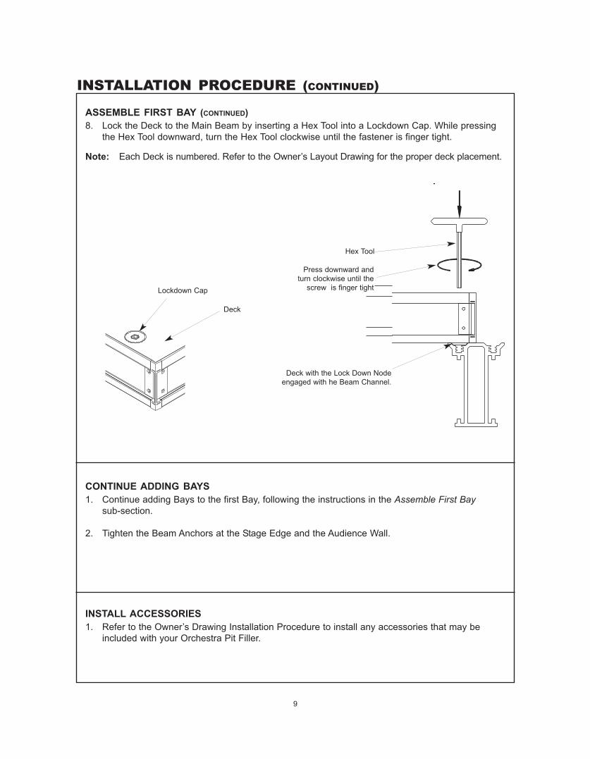
ASSEMBLE FIRST BAY (CONTINUED)8. Lock the Deck to the Main Beam by inserting a Hex Tool into a Lockdown Cap. While pressing
the Hex Tool downward, turn the Hex Tool clockwise until the fastener is finger tight.
Note: Each Deck is numbered. Refer to the Owner’s Layout Drawing for the proper deck placement.
Hex Tool
Deck with the Lock Down Nodeengaged with he Beam Channel.
CONTINUE ADDING BAYS1. Continue adding Bays to the first Bay, following the instructions in the Assemble First Bay
sub-section.
2. Tighten the Beam Anchors at the Stage Edge and the Audience Wall.
INSTALL ACCESSORIES1. Refer to the Owner’s Drawing Installation Procedure to install any accessories that may be
included with your Orchestra Pit Filler.
Lockdown Cap
Deck
Press downward andturn clockwise until the
screw is finger tight
INSTALLATION PROCEDURE (CONTINUED)

10
PIT FILLER DISASSEMBLY PROCEDURE
DISASSEMBLE DECKS1. Unlock all of the Decks by inserting the Hex Tool into each Lockdown Cap and turning the Hex
Tool counterclockwise until the Lockdown Screw pops up.
2. Remove each Deck and store it (on carts, if supplied).
DISASSEMBLE ACCESSORIES1. Remove any Accessories, such as back closures, drapery, etc., by reversing their installation
procedure.
Hex Tool
Turn counterclockwise untilthe lock pops upward.
Remove each Deck after unlockingthe Lockdown Screws

11
DISASSEMBLY PROCEDURE (CONTINUED)
DISCONNECT CROSS BEAM DIAGONAL FROM COLUMNS1. Disconnect the lower end of the Cross Beam Diagonal Braces from the Columns by removing
the Tab Lock Pin from the hole in the Column Brace Bracket and the Hole in the Diagonal.
Note: Do not remove the bolts that connect the Diagonals to the Cross Beams.
Cross Beam Diagonal Brace
Cross Beam
Tab Lock Pin Assembly
Column Brace Bracket
LOOSEN MAIN BEAM ANCHORS1. Loosen, but do not remove, the Main Beam Pit Filler Anchor Bolt from the Stage Edge or
Audience Wall. Removal of the Pit Filler Anchor Bolt will cause the Main Beams to fall whichmay cause serious injury or death.
! WARNINGTo avoid injury, donot remove the PitFiller Anchor Bolts.
Anchor Plate
Pit Filler Anchor Bolt
Anchor Slide Plate
Pit Filler Anchor Bolt
Stage Edge Assembly Audience Wall Assembly
Do not remove the bolts thatconnect the Diagonals to theCross Beams or Main Beams
Main Beam

12
DISASSEMBLY PROCEDURE (CONTINUED)
DISASSEMBLE THE UNDERSTRUCTURE1. Remove the Cross Beams and store (on storage cart, if supplied).
Cross Beam
Main Beam and Columns
13
DISASSEMBLY PROCEDURE (CONTINUED)
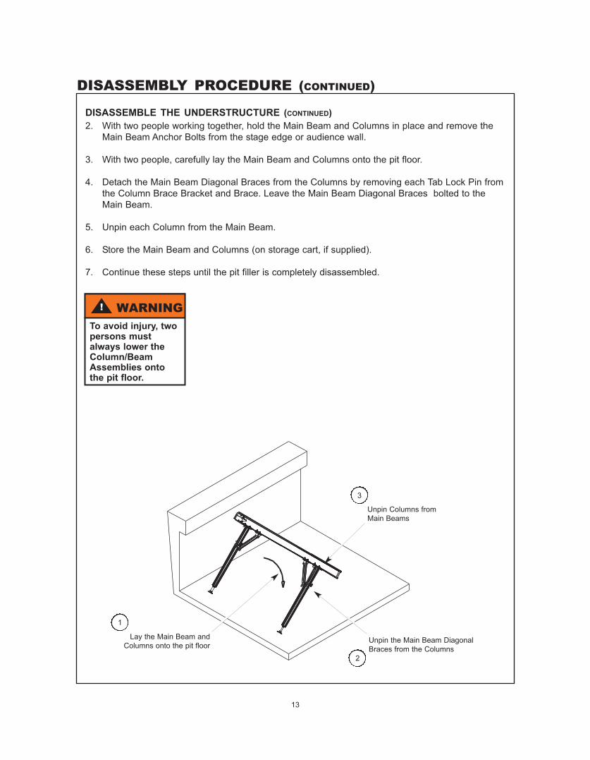
DISASSEMBLE THE UNDERSTRUCTURE (CONTINUED)2. With two people working together, hold the Main Beam and Columns in place and remove the
Main Beam Anchor Bolts from the stage edge or audience wall.
3. With two people, carefully lay the Main Beam and Columns onto the pit floor.
4. Detach the Main Beam Diagonal Braces from the Columns by removing each Tab Lock Pin fromthe Column Brace Bracket and Brace. Leave the Main Beam Diagonal Braces bolted to theMain Beam.
5. Unpin each Column from the Main Beam.
6. Store the Main Beam and Columns (on storage cart, if supplied).
7. Continue these steps until the pit filler is completely disassembled.
Lay the Main Beam andColumns onto the pit floor
Unpin the Main Beam DiagonalBraces from the Columns
Unpin Columns fromMain Beams
! WARNINGTo avoid injury, twopersons mustalways lower theColumn/BeamAssemblies ontothe pit floor.
1
2
3

TRANSPORT AND STORE PIT FILLER
14
COLUMN AND BEAM STORAGE AND TRANSPORT CART
! CAUTIONAlways lock thecasters when load-ing and unloadingthe Cart.
DECK TRANSPORT AND STORAGE CART
! CAUTIONAlways lock thecasters when load-ing and unloadingthe Cart.
Columns
Main Beams
Cross Beams
Column and Beam StorageCart shown empty
Deck Storage Cart is shownloaded with Decks
! CAUTIONAlways secure theDecks to the Cartso that they cannotfall or slide off theCart
! CAUTIONLoad the bottomracks first. Alwaysbalance the load onthe cart.

15
MAINTENANCE
DECKS1. Keep the deck surfaces clean and dry.
2. Clean with a broom, brush, or damp mop (Never saturate the hardboard surface).
3. The hardboard surface can be painted with any paint suitable for flooring.
Note: The deck edging cannot be painted.
4. Do not use oil-based cleaning products or stains on the hardboard surface.
5. Do not wax or polish the hardboard surface.
DRAPERY CLOSURES1. Drapery sections may be washed or dry-cleaned.
2. Drapery sections are attached with hook and loop (Velcro®) strips, to allow easy removal for cleaning.• Machine-wash at 120°F or lower using a mild detergent. Remove immediately after the wash cycle
completes.• Tumble-dry at permanent press (maximum 120°F or a lower temperature setting) for 20 to 30
minutes. Remove and hang immediately to prevent wrinkling. Excessive heat or drying time will detract from the permanent-press characteristics of the fabric.
• Little or no ironing is required.• Dry-clean using the Stoddard Method only at temperatures not over 120°F. Remove and hang
immediately.
OTHER PREVENTIVE MAINTENANCE1. Inspect and tighten all bolts on the beams, cross beams, and columns every six months.
2. Inspect all Lockdown Assemblies on the decks once every six months for proper function. Replace any Lockdown Assembly immediately if it does not function correctly.
3. Replace any worn, bent, or broken parts promptly to prevent injury. Contact Wenger Corporation's Parts and Product Support Department at 1-800-887-7145 for information regarding replacement parts. Or, contact Wenger Corporation at www.wengercorp.com.
16
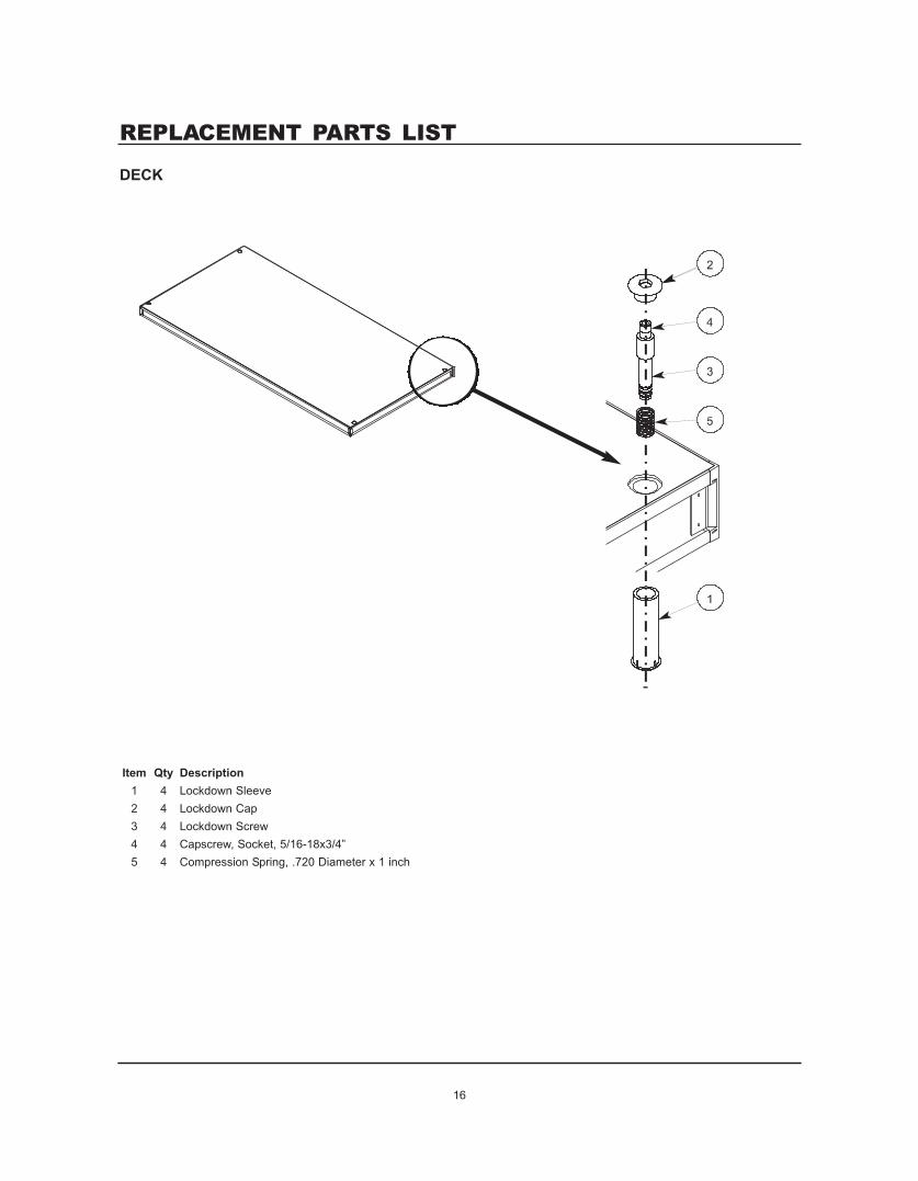
DECK
Item Qty Description1 4 Lockdown Sleeve2 4 Lockdown Cap3 4 Lockdown Screw4 4 Capscrew, Socket, 5/16-18x3/4”5 4 Compression Spring, .720 Diameter x 1 inch
REPLACEMENT PARTS LIST

17
REPLACEMENT PARTS LIST (CONTINUED)
COLUMN BRACKET
Main Beam Attachment
Intermediate BeamAttachment
Item Qty Description1 1 Column Bracket Weldment2 4 Column Bracket Clip3 4 Capscrew, 3/8-16x1-3/4”4 4 Lock Nut, 3/8-165 1 Lanyard6 1 Snap Lock Pin, 3/8”x3-1/2”
18
Main Beam Attachment
Intermediate BeamAttachment
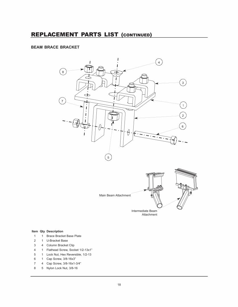
Item Qty Description1 1 Brace Bracket Base Plate2 1 U-Bracket Base3 4 Column Bracket Clip4 1 Flathead Screw, Socket 1/2-13x1”5 1 Lock Nut, Hex Reversible, 1/2-136 1 Cap Screw, 3/8-16x3”7 4 Cap Screw, 3/8-16x1-3/4”8 5 Nylon Lock Nut, 3/8-16
REPLACEMENT PARTS LIST (CONTINUED)
BEAM BRACE BRACKET

19
REPLACEMENT PARTS LIST (CONTINUED)
COLUMN FOOTItem Qty Description1 1 Leveling Foot Assembly2 1 Column Foot Insert Weldment3 2 Screw, 1/4-20x3/4” Self Tapping
COLUMN BRACE BRACKET
Column AttachmentDetail Assembled
Item Qty Description
1 1 Extrusion, Column Brace Bracket
2 1 U-Bolt, 3/8-16x4-1/8”
3 2 Nylon Lock Nut, 3/8-18
4 1 Nylon Lanyard
5 1 Pin, Tab Lock, 3/8 diameter x 2-3/4”

20
Item Qty Description1 2 Cross Beam Pin2 4 Capscrew, 3/8-16x1-1/2”3 8 Flat Washer, 3/8x1-1/4”4 4 Nylon Lock Nut, 3/8-16
REPLACEMENT PARTS LIST (CONTINUED)
CROSS BEAM
CROSS BEAM SOCKET
Cross BeamSocket
Assembled
Item Qty Description1 1 Cross Beam Socket2 2 Stud Clip3 4 Nylon Lock Nut, 5/16-18

21
REPLACEMENT PARTS LIST (CONTINUED)
ANCHOR BRACKET, STAGE EDGE
Stage Edge Anchor Bracketshown attached to Main Beam
Item Qty Description1 1 Anchor Bracket, Stage Edge2 2 Stud Clip3 4 Nylon Lock Nut, 5/16-184 1 Nylon Lanyard5 1 Pit Filler Anchor Bolt

22
REPLACEMENT PARTS LIST (CONTINUED)
ANCHOR BRACKET, AUDIENCE WALL
Audience Wall AnchorBracket Assemblyshown attached to
Main Beam
Item Qty Description1 1 Anchor Bracket, Audience Wall2 2 Bracket Clips3 2 Capscrew, 3/8-16x1-3/4”4 2 Nylon Lock Nut, 3/8-165 1 Nylon Lanyard6 1 Pit Filler Anchor Bolt7 1 Anchor Slide Bracket8 Lock Washer, 3/8”9 Flat Washer, 5/16”10 2 Wing Nut, 3/8-16

23
Item Qty Description1 1 Base, Cart, Weldment2 2 Upright, Cart Weldment3 16 Capscrew, Grade 2, Zinc Plate, 5/16-18x2-1/4”4 16 Locknut, Nylon Insert, Full, Zinc Plate, 5/16-185 4 Caster, Swivel, 6” diameter, 650 lb. capacity6 4 Capscrew, Grade 5, Zinc Plate, 1/2-13x5”7 4 Locknut, Nylon Insert, Full, Zinc Plate, 1/2-138 20 Capscrew, Grade 5, Zinc Plate, 3/8-16x2-3/4”9 20 Locknut, Nylon Insert, Full, Zinc Plate, 3/8-1610 14 Shelf, Inter. Beam, Cart, Weldment11 6 Shelf, Inter./Column, Cart, Weldment12 8 Plug, 2.00 inch Square x 14-18 Gauge, Black
REPLACEMENT PARTS LIST (CONTINUED)
STORAGE/TRANSPORT CART