overview of motion and device...
TRANSCRIPT

Integrating Motion and Orientation Sensors with Windows February 15, 2018
Abstract
This paper is intended to help OEMs, ODMs, and IHVs understand motion and orientation sensor capabilities and requirements for Windows 10 and earlier operating systems. The paper also shows how these capabilities are engineered and implemented on PC hardware platforms running Windows. This technology area involves 3D accelerometer, 3D magnetometer/compass, and 3D gyrometer sensor hardware.
This paper does not cover application development or sensor technology that is not directly related to orientation and motion detection.
This information applies to the following operating systems:Windows 10 and earlier
The current version of this paper is maintained on the Web at: Integrating Motion and Orientation Sensors
Disclaimer: This document is provided “as-is”. Information and views expressed in this document, including URL and other Internet website references, may change without notice. Some information relates to pre-released product which may be substantially modified before it’s commercially released. Microsoft makes no warranties, express or implied, with respect to the information provided here. You bear the risk of using it.Some examples depicted herein are provided for illustration only and are fictitious. No real association or connection is intended or should be inferred.This document does not provide you with any legal rights to any intellectual property in any Microsoft product. You may copy and use this document for your internal, reference purposes. © 2018 Microsoft. All rights reserved.

Integrating Motion and Orientation Sensors with Windows - 1
Document History Date ChangeFebruary 15, 2018 Updated the document to reference current technologies
December 18, 2015 Updated section about Filtering Data Update Events by Evaluating Effective RI and CS values (E-RI, E-CS)
June 10, 2013 Added restrictions for W component of a Quaternion
June 5, 2013 Moved new magnetometer text to its own section.
June 3, 2013 Replaced art that incorrectly depicted Y- and Z-axis.
April 25, 2013 Added section describing change sensitivity for the inclinometer and orientation sensors.
March 5, 2013 Updated section for calculating E-RI/E-CS
September 28, 2012 Updated value in the Pitch Rotations table
June 13, 2012 Updated Word template
September 13, 2011 First publication
ContentsOverview of Motion and Device Orientation..............................................................................4
Definitions and Terminologies................................................................................................5
Windows Motion and Orientation Features and Scenarios....................................................6
Windows 10 In-Box Motion and Orientation Scenarios......................................................6
Windows 10 Third-Party Motion and Orientation Application Scenarios...........................6
Windows Sensor Requirements..............................................................................................7
Motion/Orientation Sensor Implementation Checklists.........................................................8
IHV System Sensor Development Checklist:.......................................................................9
Reference Frames and Common Measurement Conventions for Motion and Orientation Sensors.................................................................................................................................12
Device Reference Frame...................................................................................................12
Earth Reference Frame.....................................................................................................18
Sensor Hardware to Sensor Object Mappings..................................................................19
Implementation Guidelines......................................................................................................21
Integrating Accelerometer Sensors with Windows...............................................................21
Accelerometer Part Selection Guidelines.........................................................................21
February 15, 2018© 2018 Microsoft. All rights reserved.

Integrating Motion and Orientation Sensors with Windows - 2
Accelerometer Driver Specifics.........................................................................................22
Supporting Shake Gesture Events (optional)....................................................................23
Validation of 3D Accelerometer Hardware Integration....................................................25
Integrating Gyroscope Sensors with Windows.....................................................................27
Gyroscope Part Selection Guidelines................................................................................27
Gyroscope Axes, Data Types, Capabilities.........................................................................27
3D Gyroscope Driver Specifics..........................................................................................29
Validation of 3D Gyroscope Hardware Integration...........................................................30
Integrating Magnetometer Sensors with Windows..............................................................32
Magnetometer Part Selection Guidelines.........................................................................32
Magnetometer Driver Specifics........................................................................................32
Magnetometer Accuracy..................................................................................................33
Integrating Orientation (a.k.a. Fusion) Sensors with Windows.............................................36
Orientation Sensor, compass and inclinometer integration.............................................36
Compass considerations...................................................................................................38
Inclinometer considerations.............................................................................................40
Aggregated Device Orientation Sensor Driver Specifics....................................................44
Validation of an Orientation sensor Implementation.......................................................46
9-Axis Data Accuracy Guidelines.......................................................................................46
Hardware Integration Options and Guidelines.....................................................................49
Mechanical and Electrical Engineering Considerations.....................................................49
Mechanical and Electromagnetic Considerations for Magnetometer..............................49
Component-Level Integration Options.............................................................................50
Sensor Sub-Processor (MCU) Decision Workflow.............................................................50
Connectivity Options........................................................................................................51
Leveraging In-box Driver Support.........................................................................................55
Writing a Sensor Driver.........................................................................................................58
Proper Support for Time and Magnitude Thresholds (Filtering Criteria)..........................58
Events of Interest..............................................................................................................59
Default Values for CS and RI for Motion Sensors..............................................................60
Change Sensitivity (CS, a.k.a. thresholds) for the Orientation Sensor...............................61
February 15, 2018© 2018 Microsoft. All rights reserved.

Integrating Motion and Orientation Sensors with Windows - 3
Filtering Data Update Events by Evaluating Effective report interval and change sensitivity values (E-RI, E-CS)............................................................................................61
Initial sample reading.......................................................................................................62
Power Management Best-Practices..................................................................................62
Testing and Validation..........................................................................................................64
Calibration................................................................................................................................65
Per-Model Calibration..........................................................................................................65
Per-System Calibration.........................................................................................................65
End-User Calibration and Continuous Auto-Calibration.......................................................65
Preferred: Continuous Auto-Calibration...........................................................................65
Not Preferred: End User Calibration.................................................................................65
Appendix...............................................................................................................................66
Accelerometer Measurement Conventions......................................................................66
Validation of Euler Angles (Yaw, Pitch, Roll) for 3D Inclinometer.........................................71
Yaw Tests Overview..........................................................................................................71
Test Steps for Yaw............................................................................................................71
Pitch Tests Overview.........................................................................................................73
Pitch Test Steps.................................................................................................................73
Roll Tests Overview..........................................................................................................75
Roll Test Steps..................................................................................................................76
Expected quaternion values for Euler angle rotations..............................................................78
Expected values for Tilt-Compensated Compass Heading........................................................80
February 15, 2018© 2018 Microsoft. All rights reserved.

Integrating Motion and Orientation Sensors with Windows - 4
Overview of Motion and Device OrientationThis paper is intended to help OEMs, ODMs, and IHVs understand motion and orientation sensor capabilities and requirements for Windows 10 and also to document how these capabilities are engineered and implemented on PC hardware platforms running Windows 10. This technology area involves 3D accelerometer, 3D magnetometer/compass, and 3D gyroscope sensor hardware.
This paper does not cover application development or sensor technology that is not directly related to orientation and motion detection.
February 15, 2018© 2018 Microsoft. All rights reserved.

Integrating Motion and Orientation Sensors with Windows - 5
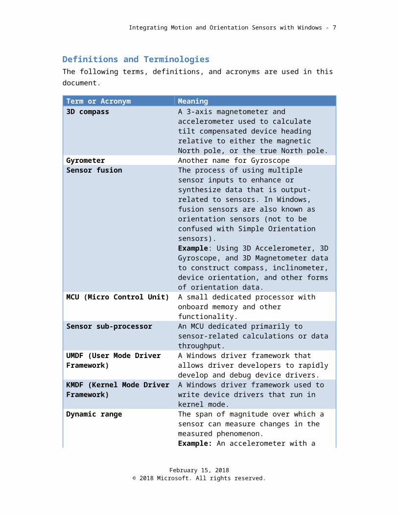
Definitions and TerminologiesThe following terms, definitions, and acronyms are used in this document.
Term or Acronym Meaning3D compass A 3-axis magnetometer and accelerometer used to
calculate tilt compensated device heading relative to either the magnetic North pole, or the true North pole.
Gyrometer Another name for GyroscopeSensor fusion The process of using multiple sensor inputs to
enhance or synthesize data that is output- related to sensors. In Windows, fusion sensors are also known as orientation sensors (not to be confused with Simple Orientation sensors).Example: Using 3D Accelerometer, 3D Gyroscope, and 3D Magnetometer data to construct compass, inclinometer, device orientation, and other forms of orientation data.
MCU (Micro Control Unit) A small dedicated processor with onboard memory and other functionality.
Sensor sub-processor An MCU dedicated primarily to sensor-related calculations or data throughput.
UMDF (User Mode Driver Framework)
A Windows driver framework that allows driver developers to rapidly develop and debug device drivers.
KMDF (Kernel Mode Driver Framework)
A Windows driver framework used to write device drivers that run in kernel mode.
Dynamic range The span of magnitude over which a sensor can measure changes in the measured phenomenon. Example: An accelerometer with a dynamic range of -3.0G to +3.0G on each axis.
HLK Windows hardware lab kitRI Report interval. The fastest interval (expressed as
the period between events) at which connected clients are requesting data
CS Change sensitivity. Also known as ‘Thresholds’. The smallest magnitude threshold that connected clients are requesting data for (or default, if no client has set this property).
February 15, 2018© 2018 Microsoft. All rights reserved.

Integrating Motion and Orientation Sensors with Windows - 6
Windows Motion and Orientation Features and ScenariosMotion and Orientation sensors support important in-box and third-party application development scenarios. The following list covers some of these scenarios.
Windows 10 In-Box Motion and Orientation Scenarios1. Screen auto-rotation: Requires that 3D accelerometer hardware be properly
integrated (follows guidelines specified in this paper and in the Windows Hardware Lab Kit).
2. Enhanced human presence detection: Requires that 3D accelerometer hardware be properly integrated. A sustained change in physical device orientation is used as a means to detect the presence of a user.
Windows 10 Third-Party Motion and Orientation Application Scenarios1. 2D casual games:
a. Labyrinth-style rolling ball game2. 3D interactive games: Device motion/orientation as input device
a. Steering wheel-style car racing gameb. First-person shooter style games
3. 3D augmented reality and virtual reality applications: a. 3D photo-realistic mapping application with superimposed points of interestb. Indoor navigation applications
February 15, 2018© 2018 Microsoft. All rights reserved.
Integrating Motion and Orientation Sensors with Windows - 7
Windows Sensor RequirementsThe following table outlines the various PC form-factors and corresponding motion/orientation sensor requirements.
P1 Sensor Category Slate / Convertible
Laptop
Non-convertible Laptop
Desktop / AIO
3D Accelerometer Required If Implemented If Implemented3D Gyroscope Required If Implemented If Implemented3D Compass Required If Implemented If ImplementedOrientation Required If Implemented If Implemented
Please see the hardware lab kit at https://docs.microsoft.com/en-us/windows-hardware/test/hlk/windows-hardware-lab-kit for more details regarding sensors and system requirements.
February 15, 2018© 2018 Microsoft. All rights reserved.

Integrating Motion and Orientation Sensors with Windows - 8
Motion/Orientation Sensor Implementation ChecklistsThe following list represents the various development activities and validation exercises that ensure that motion and orientation sensors function properly on PC hardware running Windows 10.
OEM/ODM System Sensor Integration Checklist:Task Description1. Check sensor support requirements
for the PC form-factor being builtBased on the form-factor for the PC being built, different requirements apply for sensors being present as well as implemented capabilities.
See Testing and Validation for more information regarding required sensor hardware and validation.
2. Use part selection guidelines to select the appropriate sensor components and any related parts
As a part of engineering the system, select parts that have the appropriate capabilities and features in order to satisfy the functionality, performance, and cost requirements for the system in question.
See the part selection guidelines in each sensor-specific section in this document for more details.
3. Decide on a motion/orientation sensor driver strategy
Based on the capabilities of the sensor components and the availability of in-box sensor drivers for Windows 10, decide which drivers will be used or implemented, and follow the appropriate device firmware implementation or driver implementation guidelines.
See Leveraging In-box Driver Support for more information about using the in-box driver support for motion/orientation sensors in Windows 10.
See Writing a Sensor Driver for more information regarding writing your own driver for motion/orientation sensors.
4. Follow guidance when engineering the system
Make sure to follow electrical and mechanical engineering guidance in this document. In addition to the information included in this document, seek guidance from the supplying IHV partners in order to avoid issues with
February 15, 2018© 2018 Microsoft. All rights reserved.

Integrating Motion and Orientation Sensors with Windows - 9
heat, electromagnetic interference, and other problematic conditions. Mechanical/electrical considerations such as placement of Hall effect sensor magnets and other sources of interference should be carefully designed and compensated for when performing initial calibration for sensors for a particular PC. Orientation of measurement axes should be considered when deciding placement for sensor components.
5. Validate system integration and features
Confirm that sensors are oriented correctly and that in-box features perform according to the guidelines outlined in this document.
See Testing and Validation for more information regarding required sensor hardware and validation
6. Run system validation tests as appropriate
Once a system has sensors integrated and basic functionality validated, the system validation tests need to be run to validate proper performance and functionality.
See Testing and Validation for more information regarding required sensor hardware and validation
7. Calibration and configuration on factory floor
Work with IHV to integrate calibration and configuration activities into production process and workflow. This can include sensor self-test routines, per-unit calibration, and other configuration activities.
IHV System Sensor Development Checklist:Task Description1. Work with the customer (OEM /
IHV) to understand the type of system being engineered.
Consult the Windows Sensor Requirements table in this document and the system requirements on https://docs.microsoft.com/en-us/windows-hardware/test/hlk/windows-hardware-lab-kit in order to determine which sensors and corresponding capabilities are required.
2. Establish an inventory of sensor components (such as a 3D accelerometer, 3D magnetometer, and 3D Gyroscope)
Based on the following part selection guideline sections in this document:3D Accelerometer3D Compass3D Gyroscope
February 15, 2018© 2018 Microsoft. All rights reserved.

Integrating Motion and Orientation Sensors with Windows - 10
Determine which parts will be used for the system being engineered.
3. Decide whether or not a sensor sub-processor (MCU) will be utilized for the sensor system in question
Decide if an MCU will be used based on cost, integration and driver specifics, power trade-offs, and other factors.
For more information, please consult the following sections:Sensor Sub Processor Decision Workflow
4. Work with OEM/ODM partner to design schematic for sensor connectivity
After all components (including sensors and any MCU or related parts) are selected, determine how the sensor components will be wired up to the host and/or MCU.
Please see Connectivity Options for more details.
5. Inventory software dependencies and deliverables
Based on the type of system being implemented, make a list of the required driver and software components and establish ownership for these deliverables, including device firmware.
For more information see:Leveraging In-box HID Driver SupportConnectivity OptionsWriting a Sensor Driver
6. Write device firmware and develop any drivers needed to support sensors.
See: Leveraging In-box Driver SupportWriting a Sensor Driver
7. Perform basic validation of sensor data
Perform basic validation of the orientation of sensors and sensor data as integrated with the Windows Sensor Platform.
See:Validation of 3D Accelerometer Hardware IntegrationValidation of 3D Gyroscope Hardware IntegrationValidation of 3D Compass Hardware IntegrationValidation of Orientation sensor Implementation
8. Run device validation tests, verify device drivers and device via HLK process as applicable
Ensure that the sensor device(s) will pass compatibility testing. Pass HLK validation for the device(s).
Consult the Windows Sensor Requirements table in this document and the system
February 15, 2018© 2018 Microsoft. All rights reserved.

Integrating Motion and Orientation Sensors with Windows - 11
requirements on https://docs.microsoft.com/en-us/windows-hardware/test/hlk/windows-hardware-lab-kit in order to determine which sensors and corresponding capabilities are required.
9. Run system validation tests on PC hardware
Ensure that all sensor features are properly supported for the PC form-factor being built. Pass HLK validation for the system (OEM does this).
Consult the Windows Sensor Requirements table in this document and the system requirements on https://docs.microsoft.com/en-us/windows-hardware/test/hlk/windows-hardware-lab-kit in order to determine which sensors and corresponding capabilities are required.
February 15, 2018© 2018 Microsoft. All rights reserved.

Integrating Motion and Orientation Sensors with Windows - 12
Reference Frames and Common Measurement Conventions for Motion and Orientation SensorsThere are several considerations and conventions that need to be observed and implemented in order to properly expose motion and orientation sensors on Windows.
The guidance in this section of the document is in accordance with the W3C Device Orientation Draft Specification. Please read the W3C device orientation document and become familiar with the measurement conventions.
All data types use the same convention for X, Y, Z axis alignment and orientation relative to each form-factor chassis. For angular measurements, the right-hand rule is exclusively used to map positive and negative angular measurements relative to the X, Y, Z axes.
The following sections describe the reference frames that are relevant to motion/orientation sensing, and also outline which sensors use which reference frames.
Device Reference FrameThe device reference frame is defined for each PC form-factor and provides an X, Y, Z reference frame that is fixed with respect to the hardware chassis. For the slate PC, this reference frame does not change because the slate PC form factor does not convert or change configurations.
For non-slate convertible form-factors, the Slate PC mode is the “primary” mode for accelerometer. Sensors, regardless of being placed in the screen or the base, should be projected as if they were located in the screen (as in the case of the Slate PC).
For clamshell form-factors, axis orientation should be projected to be relative to the screen regardless of where the sensors were integrated. For systems unable to detect the angle of the screen, sensors should be projected as if the screen was at a 90 degree angle to the base.
For devices unable to detect the angle of the screen, there are clear mappings for convertible form factors. These mapping can be done as so:
Sensor Location Screen Base Base Base
Form Factor N/A Clamshell at 90 degrees
Fold-backwards Hinge
Swivel Hinge
x x x x -x
y y z -y -y
February 15, 2018© 2018 Microsoft. All rights reserved.

Integrating Motion and Orientation Sensors with Windows - 13
z z -y -z z
Slate PC
Figure 1: Landscape Slate PC (Single Mode) Chassis and Axis Convention for Motion/Orientation Sensors
Figure 2: Landscape Slate PC with Detachable keyboard Chassis and Axis Convention for Motion/Orientation Sensors
February 15, 2018© 2018 Microsoft. All rights reserved.

Integrating Motion and Orientation Sensors with Windows - 14
Figure 3: Portrait Slate PC (Single Mode) Chassis and Axis Convention for Motion/Orientation Sensors – Same axis convention as any portrait-first devices
Swivel Hinge Convertible PC
Figure 4: Swivel Hinge Convertible PC (Clamshell PC Mode) Chassis and Axis Convention for Motion/Orientation Sensors
February 15, 2018© 2018 Microsoft. All rights reserved.

Integrating Motion and Orientation Sensors with Windows - 15
Figure 5: Swivel Hinge Convertible PC (Converting mode – axes are undefined or arbitrary) Chassis and Axis Convention for Motion/Orientation Sensors
Figure 6: Swivel Hinge Convertible PC (Slate PC Mode) Chassis and Axis Convention for Motion/Orientation Sensors (Note: Windows Logo is located at the bottom of screen and +Y axis points towards the top of the screen)
February 15, 2018© 2018 Microsoft. All rights reserved.

Integrating Motion and Orientation Sensors with Windows - 16
Clamshell PC (Laptop)
Figure 7: Clamshell PC Chassis and Axis Convention for Motion/Orientation Sensors
Slide-out Keyboard Slate PC
Figure 8: Slide-out Keyboard PC (Keyboard Extended Mode) Chassis and Axis Convention for Motion/Orientation Sensors
February 15, 2018© 2018 Microsoft. All rights reserved.

Integrating Motion and Orientation Sensors with Windows - 17
Figure 9: Slide-out Keyboard PC (Slate PC Mode) Chassis and Axis Convention for Motion/Orientation Sensors
Convertible Flipper PC
Figure 10: Convertible Flipper PC (Clamshell/Converting Mode) Chassis and Axis Convention for Motion/Orientation Sensors
February 15, 2018© 2018 Microsoft. All rights reserved.

Integrating Motion and Orientation Sensors with Windows - 18
Figure 11: Convertible Flipper PC (Slate PC Mode) Chassis and Axis Convention for Motion/Orientation Sensors
Earth Reference FrameThe earth reference frame consists of the following reference points:
1. Ground Reference Plane: An X, Y, Z reference frame that is represented on a level surface (plane) below the PC.
2. North Pole: Actual North Pole at the point around which the axis that the earth spins projects through.
3. Magnetic North Pole: The natural center of the magnetic field inherent to the earth above the equator.
This diagram uses the following reference points:
February 15, 2018© 2018 Microsoft. All rights reserved.

Integrating Motion and Orientation Sensors with Windows - 19
North Pole: The geometric “top” of the earth Magnetic North Pole: The upper magnetic center of the earth CH: Compass heading (relative to true North heading in this case) Y: The yaw angle of the device (360° - Compass heading). Note that yaw
measurement is the rotation of the device around the axis pointing out of the screen (Z-axis). The relationship between yaw and compass heading is only applicable when the device is on a flat and level plane.
Here we see the relationship between the device reference frame (X, Y, Z axes labeled on a slate device) and the earth reference frame (level plane on earth’s surface below the device). In this case, true North heading is referenced, since the North Pole is being used to determine heading. If the Magnetic North Pole were used in instead of the North Pole, we could illustrate magnetic North heading.
Sensor Hardware to Sensor Object MappingsAt a high level, the following diagram depicts the inputs and outputs for a full motion/orientation 9-axis sensor fusion capable implementation:
The following table lists the mapping between sensors that are exposed via the Windows sensor platform (by a sensor driver or multiple sensor drivers) and the underlying sensor hardware that is used to generate the corresponding sensor data.
Sensor exposed in API Derived from sensor hardware3D AccelerometerData fields:
X Acceleration Y Acceleration
3D Accelerometer
February 15, 2018© 2018 Microsoft. All rights reserved.

Integrating Motion and Orientation Sensors with Windows - 20
Z AccelerationEvents:
ShakeSee Integrating 3D Accelerometer Sensors for more details.
3D Compass Data fields: Tilt compensated magnetic heading Tilt compensated true north heading (optional;
provide if location data is available to firmware or driver)
See Integrating Compass Sensors for more details.
3D Accelerometer 3D Magnetometer 3D Gyroscope (only required
for slate)
3D GyroscopeData fields:
X Rotational Velocity Y Rotational Velocity Z Rotational Velocity
See Integrating Gyroscope Sensors for more details.
3D Gyroscope
3D Inclinometer Data Fields: Yaw (Z-Axis) Pitch (X-Axis) Roll (Y-Axis)See Integrating Orientation Sensors for more details.
3D Accelerometer 3D Magnetometer 3D Gyroscope
Device Orientation (Quaternion)Data Fields: QuaternionSee Integrating Orientation Sensors for more details.
3D Accelerometer 3D Magnetometer 3D Gyroscope
February 15, 2018© 2018 Microsoft. All rights reserved.

Integrating Motion and Orientation Sensors with Windows - 21
Implementation GuidelinesThe remainder of this paper provides details you’ll need when implementing the required functionality in your hardware.
Integrating Accelerometer Sensors with WindowsAccelerometers are a key hardware component for screen rotation and game/orientation application scenarios. For slate PC hardware, they also play an important role in sensor fusion (along with magnetometer and gyro data, as well). This section covers details regarding accelerometer part selection, sensor metadata, and simple validation of proper accelerometer integration.
Please refer to Accelerometer Measurement Conventions for more information about how force and acceleration is measured by accelerometers integrated with Windows PC hardware.
Accelerometer Part Selection Guidelines
Types of accelerometersAccelerometers for consumer electronics are typically 3D (three-axis measurement device). In order to support orientation detection and motion/gesture detection for Windows scenarios, 3D accelerometers are required.
Dynamic rangeThe dynamic range of an accelerometer refers to the magnitude of acceleration that can be measured. In some cases the dynamic range of acceleration measurement can be configured for a particular accelerometer. If the accelerometer is configured to measure a wider range of acceleration values, the trade-off is typically lower resolution data.
Range (as configured on system – outputs of accelerometer): +/- 4.0G
Accuracy and Resolution Non-linearity: 1.0% Noise: 350ug/rtHz @10Hz Initial calibration tolerance: +/-3%, +/-50mg
Sensitivity Scale Factor 0.12mg/LSB @ ±4g
Sampling rates (hardware) Minimum: 100 Hz Optimal: 200+ Hz
Note that this frequency indicates hardware sampling rate capability. Data from motion/orientation sensors (including accelerometers) should be filtered based on time
February 15, 2018© 2018 Microsoft. All rights reserved.

Integrating Motion and Orientation Sensors with Windows - 22
(report interval) and magnitude (change sensitivity). See Writing a Sensor Driver for more detail.
Power consumption Optimal: ~350uA or less
Accelerometer Driver SpecificsSee Writing a Sensor Driver for general information and guidelines.
Accelerometers integrated with PC hardware should use the following conventions for X, Y, Z axis direction and signage.
3D Accelerometer PropertiesSensor Property Read/Write - Values/Range Description
Sensor category (DEVPKEY_Sensor_Category)
Read-OnlyGUID_SensorCategory_Motion
The sensor category
Sensor type(DEVPKEY_Sensor_Type)
Read-OnlyGUID_SensorType_Accelerometer3D
The sensor type
Connection type(DEVPKEY_Sensor_ConnectionType)
Read-OnlySensorConnectionType_Integrated for internal sensors
Describes how the sensor is connected to the PC.
Manufacturer(DEVPKEY_Sensor_Manufacturer)
Read-OnlyString: <Driver or sensor manufacturer>
Describes what company manufactures the device and or provides the driver.
Sensor unique ID(DEVPKEY_Sensor_PersistentUniqueId)
Read-OnlyThis is a unique GUID for the sensor, unique as exposed on a particular machine, generated during device install time. (Reinstalling the device causes new GUIDs to be generated.)
Uniquely identifies the sensor.
Sensor model(DEVPKEY_Sensor_Model)
Read-OnlyString: <Driver or sensor model>
The model of sensor or device.
Change sensitivity Read-WriteFloat, per data field reported to the sensor class extension through EvtSensorGetDataThresholds
The smallest magnitude threshold that connected clients are requesting data for (or default, if no client has set this property).
This value is used by the driver to determine when a meaningful change in acceleration is
February 15, 2018© 2018 Microsoft. All rights reserved.

Integrating Motion and Orientation Sensors with Windows - 23
detected.
Current report interval
Read-WriteInteger (milliseconds) reported to the sensor class extension through EvtSensorGetDataInterval
The fastest interval (expressed as the period between events) at which connected clients are requesting data (or default, if no client as set this property).
3D Accelerometer Data Fields
Sensor Data Field Description
PKEY_SensorData_AccelerationX_Gs X-axis acceleration, in g's. (VT_R8)
PKEY_SensorData_AccelerationY_Gs Y-axis acceleration, in g's. (VT_R8)PKEY_SensorData_AccelerationZ_Gs Z-axis acceleration, in g's. (VT_R8)
3D Accelerometer Events (optional)Sensor Event Description
PKEY_SensorData_Shake The event ID used when accelerometer hardware has detected that a shake event has occurred.
Supporting Shake Gesture Events (optional)Use the following guidelines when implementing a shake detection algorithm in device firmware or a sensor device driver. For power management reasons, use only the accelerometer to detect shake gestures.
Frequency: The oscillation frequency for shake detection should range between 200ms and 400ms period.
Magnitude: The magnitude of linear acceleration change should be between ~2.0G and ~4.0G
Direction: Shake gesture can be relative to any change in device direction (acceleration) and therefore, the net direction of the collective linear acceleration vector should be evaluated such that changes in direction approximating motion along a straight line (in one direction and then an opposite direction in a close to linear path) are detected.
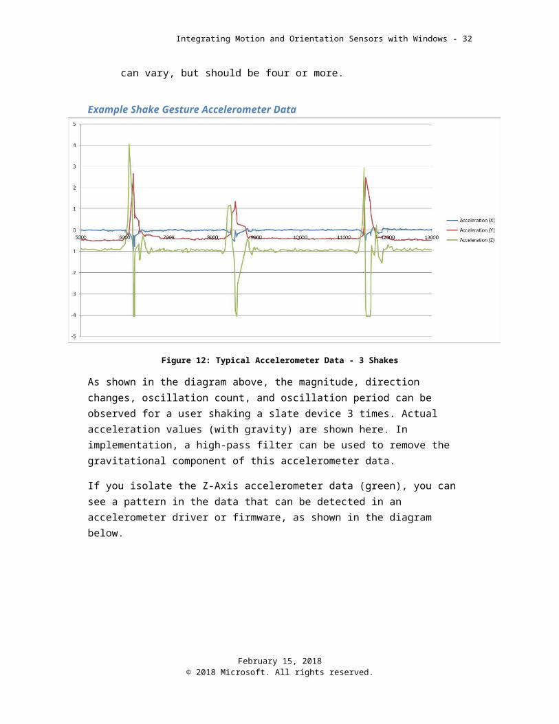
Oscillation Count: For the purposes of this algorithm, the oscillations can be broken down into individual “direction changes” (See figure 13). The number of direction changes can vary, but should be four or more.
February 15, 2018© 2018 Microsoft. All rights reserved.

Integrating Motion and Orientation Sensors with Windows - 24
Example Shake Gesture Accelerometer Data
Figure 12: Typical Accelerometer Data - 3 Shakes
As shown in the diagram above, the magnitude, direction changes, oscillation count, and oscillation period can be observed for a user shaking a slate device 3 times. Actual acceleration values (with gravity) are shown here. In implementation, a high-pass filter can be used to remove the gravitational component of this accelerometer data.
If you isolate the Z-Axis accelerometer data (green), you can see a pattern in the data that can be detected in an accelerometer driver or firmware, as shown in the diagram below.
February 15, 2018© 2018 Microsoft. All rights reserved.

Integrating Motion and Orientation Sensors with Windows - 25
Figure 13: Acceleration direction changes for shake event
The key points of interest for this example set of data are as follows:
First direction change (initiation of shake detection sequence) Second direction change Third direction change Fourth direction change (shake gesture detected) Fifth direction change Sixth direction change Seventh direction change Stabilization
This data set is an example for illustrative purposes only. In order to properly detect a shake motion sequence, the algorithm needs to be capable of detecting oscillations along the Z-axis that are similar in form to the example above. While shake detection algorithms can also incorporate X and Y axis accelerometer data, only Z-axis accelerometer data and motion is used to evaluate shake detection performance on Windows 10 systems. Note that accelerometer shake event is optional for Windows 10 sensor implementations.
Validation of 3D Accelerometer Hardware IntegrationIn order to validate that accelerometer hardware is properly integrated, perform the following tests. In some cases, you should use the Sensor Diagnostic Tool.
1. Use the Sensor Diagnostic Tool to examine the 3D accelerometer under test. Expand the sensors and click on the 3D accelerometer. Validate that you see data updates. For a slate PC, perform the following data integrity checks:
February 15, 2018© 2018 Microsoft. All rights reserved.

Integrating Motion and Orientation Sensors with Windows - 26
a. Lay the device on a flat surface with the screen pointing up – acceleration values should be the following:X = ~0.0, Y = ~0.0, Z = ~-1.0
b. Hold the device with the right hand side pointing upwards up – acceleration values should be the following:X = ~-1.0, Y = ~0.0, Z = ~0.0
c. Hold the device with the top of the screen pointing upwards up – acceleration values should be the following:X = ~0.0, Y = ~-1.0, Z = ~0.0
2. Test automatic screen rotation – Ensure that your accelerometer is active and that you have a display that is capable of rotation (check display properties, make sure “Auto” setting is active)
a. Hold the device vertically and in portrait mode with the screen pointing towards your chest. The content on the screen should appear properly oriented.
b. Switch the device orientation to landscape mode and wait a few seconds. The screen should rotate so that content is properly oriented.
c. Switch the device orientation to inverted portrait mode and wait a few seconds. The screen should rotate so that content is properly oriented.
d. Switch the device orientation to inverted landscape mode and wait a few seconds. The screen should rotate so that content is properly oriented.
Accelerometer power management and auto-rotation
Note that the accelerometer will still draw power even if the user disables the auto-rotation feature on a device. (The sensor platform requires that the accelerometer is always enabled to provide support for the SimpleOrientation sensor.)
February 15, 2018© 2018 Microsoft. All rights reserved.

Integrating Motion and Orientation Sensors with Windows - 27
Integrating Gyroscope Sensors with Windows
Gyroscope Part Selection Guidelines
Dynamic rangeThe dynamic range of a gyroscope refers to the magnitude of rotational velocity which can be measured. In some cases the dynamic range of rotational velocities can be configured for a particular gyroscope. If the gyroscope is configured to measure a wider range of rotational velocities, the trade-off is typically lower resolution data.
Minimum: -720dps to +720dps Optimal: -2000dps to +2000dps
Accuracy and Resolution Non-linearity: 0.2% Noise: 0.05dps-rms@100Hz Sensitivity scale factor tolerance @25degC: +/-3%, ZRO @ 25degC: +/-20dps
Sensitivity Scale Factor 16.4 LSB/dps @ ±2000dps 32.8 LSB/dps @ ±1000dps 65.5 LSB/dps @ ±500dps 131 LSB/dps @ ±250dps
Sampling rates (hardware) Recommended: 100hz+
Power consumption Recommended: 7000uA or less
Gyroscope Axes, Data Types, Capabilities
February 15, 2018© 2018 Microsoft. All rights reserved.

Integrating Motion and Orientation Sensors with Windows - 28
Figure 14: Gyroscope Axis Definitions and Rotation Directions (Slate) – Shares axis and angular measurement convention with Inclinometer
Figure 15: Gyroscope Axis Definitions and Rotation Directions (clamshell) – Shares axis and angular measurement convention with Inclinometer
February 15, 2018© 2018 Microsoft. All rights reserved.

Integrating Motion and Orientation Sensors with Windows - 29
3D Gyroscope Driver SpecificsSee Writing a Sensor Driver for general information and guidelines.
The Windows convention for rotational velocity measurement (gyroscope sensor data) is consistent with the W3C Device Orientation specification.
3D Gyroscope Properties
Sensor Property Read/Write - Values/Range Description
Sensor category (DEVPKEY_Sensor_Category)
Read-OnlyGUID_SensorCategory_Motion
The sensor category
Sensor type(DEVPKEY_Sensor_Type)
Read-OnlyGUID_SensorType_Gyrometer3D
The sensor type
Connection type(DEVPKEY_Sensor_ConnectionType)
Read-OnlySensorConnectionType_Integrated for internal sensors
Describes how the sensor is connected to the PC.
Manufacturer(DEVPKEY_Sensor_Manufacturer)
Read-OnlyString: <Driver or sensor manufacturer>
Describes what company manufactures the device and or provides the driver.
Sensor unique ID(DEVPKEY_Sensor_PersistentUniqueId)
Read-OnlyThis is a unique GUID for the sensor, unique as exposed on a particular machine, generated during device install time. (Reinstalling the device causes new GUIDs to be generated.)
Uniquely identifies the sensor.
Sensor model(DEVPKEY_Sensor_Model)
Read-OnlyString: <Driver or sensor model>
The model of sensor or device.
Change sensitivity Read-WriteFloat, per data field reported to the sensor class extension through EvtSensorGetDataThresholds
The smallest magnitude threshold that connected clients are requesting data for (or default, if no client has set this property).This value is used by the driver to determine when a meaningful change in angular velocity is detected.
Current report interval
Read-WriteInteger (milliseconds) reported to the sensor class extension through EvtSensorGetDataInterval
The fastest interval (expressed as the period between events) at which connected clients are requesting data (or default, if no
February 15, 2018© 2018 Microsoft. All rights reserved.

Integrating Motion and Orientation Sensors with Windows - 30
client as set this property).
3D Gyroscope Data FieldsSensor Data Field Description
PKEY_SensorData_AngularVelocityX_DegreesPerSecond
Angular velocity around the X-axis, in degrees per second. (VT_R8)
PKEY_SensorData_AngularVelocityY_DegreesPerSecond
Angular velocity around the Y-axis, in degrees per second. (VT_R8)
PKEY_SensorData_AngularVelocityZ_DegreesPerSecond
Angular velocity around the Z-axis, in degrees per second. (VT_R8)
3D Gyroscope EventsN/A
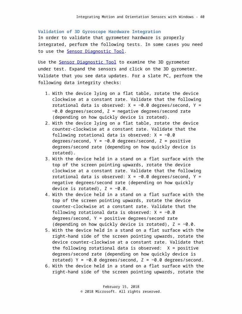
Validation of 3D Gyroscope Hardware IntegrationIn order to validate that gyrometer hardware is properly integrated, perform the following tests. In some cases you need to use the Sensor Diagnostic Tool.
Use the Sensor Diagnostic Tool to examine the 3D gyrometer under test. Expand the sensors and click on the 3D gyrometer. Validate that you see data updates. For a slate PC, perform the following data integrity checks:
1. With the device lying on a flat table, rotate the device clockwise at a constant rate. Validate that the following rotational data is observed: X = ~0.0 degrees/second, Y = ~0.0 degrees/second, Z = negative degrees/second rate (depending on how quickly device is rotated).
2. With the device lying on a flat table, rotate the device counter-clockwise at a constant rate. Validate that the following rotational data is observed: X = ~0.0 degrees/second, Y = ~0.0 degrees/second, Z = positive degrees/second rate (depending on how quickly device is rotated).
3. With the device held in a stand on a flat surface with the top of the screen pointing upwards, rotate the device clockwise at a constant rate. Validate that the following rotational data is observed: X = ~0.0 degrees/second, Y = negative degrees/second rate (depending on how quickly device is rotated), Z = ~0.0.
4. With the device held in a stand on a flat surface with the top of the screen pointing upwards, rotate the device counter-clockwise at a constant rate. Validate that the following rotational data is observed: X = ~0.0 degrees/second, Y = positive degrees/second rate (depending on how quickly device is rotated), Z = ~0.0.
5. With the device held in a stand on a flat surface with the right-hand side of the screen pointing upwards, rotate the device counter-clockwise at a constant rate. Validate that the following rotational data is observed: X = positive degrees/second rate (depending on how quickly device is rotated) Y = ~0.0 degrees/second, Z = ~0.0 degrees/second.
February 15, 2018© 2018 Microsoft. All rights reserved.

Integrating Motion and Orientation Sensors with Windows - 31
6. With the device held in a stand on a flat surface with the right-hand side of the screen pointing upwards, rotate the device clockwise at a constant rate. Validate that the following rotational data is observed: X = negative degrees/second rate (depending on how quickly device is rotated) Y = ~0.0 degrees/second, Z = ~0.0 degrees/second.
February 15, 2018© 2018 Microsoft. All rights reserved.
Integrating Motion and Orientation Sensors with Windows - 32
Integrating Magnetometer Sensors with WindowsMagnetometers are used by the compass, the inclinometer, and the orientation sensor. This section of the paper outlines key concepts related to this device.
Magnetometer Part Selection Guidelines
Dynamic Range (Gauss) Minimum: +/-1000uT Maximum: N/A
Accuracy and Resolution Non-linearity: ±0.1 (FS ± 100uT) Noise: 0.5 uT / rtHz @8Hz ODR Offset: <300 uT
Sensitivity Scale Factor Optimal: 0.3uT / LSB
Sampling rates (hardware) 8hz +
Power consumption Acceptable: 350uA
Magnetometer Driver Specifics
3D Magnetometer PropertiesSensor Property Read/Write - Values/Range Description
Sensor category (DEVPKEY_Sensor_Category)
Read-OnlyGUID_SensorCategory_Motion
The sensor category
Sensor type(DEVPKEY_Sensor_Type)
Read-OnlyGUID_SensorType_Magnetometer3D
The sensor type
Connection type(DEVPKEY_Sensor_ConnectionType)
Read-OnlySensorConnectionType_Integrated for internal sensors
Describes how the sensor is connected to the PC.
Manufacturer(DEVPKEY_Sensor_Manufacturer)
Read-OnlyString: <Driver or sensor manufacturer>
Describes what company manufactures the device and or provides the driver.
Sensor unique ID(DEVPKEY_Sensor_PersistentUniqueId)
Read-OnlyThis is a unique GUID for the sensor, unique as exposed on a particular machine, generated during device
Uniquely identifies the sensor.
February 15, 2018© 2018 Microsoft. All rights reserved.

Integrating Motion and Orientation Sensors with Windows - 33
install time. (Reinstalling the device causes new GUIDs to be generated.)
Sensor model(DEVPKEY_Sensor_Model)
Read-OnlyString: <Driver or sensor model>
The model of sensor or device.
Change sensitivity Read-WriteFloat, per data field reported to the sensor class extension through EvtSensorGetDataThresholds
The smallest magnitude threshold that connected clients are requesting data for (or default, if no client has set this property).This value is used by the driver to determine when a meaningful change in magnetic field is detected.
Current report interval
Read-WriteInteger (milliseconds) reported to the sensor class extension through EvtSensorGetDataInterval
The fastest interval (expressed as the period between events) at which connected clients are requesting data (or default, if no client as set this property).
3D Magnetometer Data FieldsSensor Data Field Description
PKEY_SensorData_MagneticFieldStrengthX_Microteslas
X-axis magnetic field strength, in micro teslas. (VT_R8)
PKEY_SensorData_MagneticFieldStrengthY_Microteslas
Y-axis magnetic field strength, in g's. (VT_R8)
PKEY_SensorData_MagneticFieldStrengthZ_Microteslas
Z-axis magnetic field strength, in g's. (VT_R8)
PKEY_SensorData_MagnetometerAccuracy Accuracy of the magnetic field readings. Can be MagnetometerAccuracy_Unreliable, MagnetometerAccuracy_Approximate, or MagnetometerAccuracy_High
Magnetometer AccuracyMagnetometer sensors are susceptible to electromagnetic field interference from the surrounding environment or the computing device itself. Because orientation sensors such as compass, inclinometer, and device orientation rely on magnetometer data, as interference increases, sensor accuracy degrades. In many cases dynamic calibration is needed to account for the changing electromagnetic environment, which requires the device to be moved around all three device axis.
February 15, 2018© 2018 Microsoft. All rights reserved.

Integrating Motion and Orientation Sensors with Windows - 34
The Windows Sensor Platform supports a magnetometer accuracy data field to be included in each orientation input report. Magnetometer accuracy is one of:
unreliable approximate high
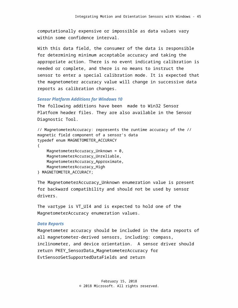
These values indicate how closely the data represents the actual heading of the device with respect to a horizontal plane. Often computing an absolute accuracy in degrees is computationally expensive or impossible as data values vary within some confidence interval.
With this data field, the consumer of the data is responsible for determining minimum acceptable accuracy and taking the appropriate action. There is no event indicating calibration is needed or complete, and there is no means to instruct the sensor to enter a special calibration mode. It is expected that the magnetometer accuracy value will change in successive data reports as calibration changes.
Sensor Platform Additions for Windows 10The following additions have been made to Win32 Sensor Platform header files. They are also available in the Sensor Diagnostic Tool.
// MagnetometerAccuracy: represents the runtime accuracy of the // magnetic field component of a sensor's datatypedef enum MAGNETOMETER_ACCURACY{ MagnetometerAccuracy_Unknown = 0, MagnetometerAccuracy_Unreliable, MagnetometerAccuracy_Approximate, MagnetometerAccuracy_High} MAGNETOMETER_ACCURACY;
The MagnetometerAccuracy_Unknown enumeration value is present for backward compatibility and should not be used by sensor drivers.
The vartype is VT_UI4 and is expected to hold one of the MagnetometerAccuracy enumeration values.
Data ReportsMagnetometer accuracy should be included in the data reports of all magnetometer-derived sensors, including: compass, inclinometer, and device orientation. A sensor driver should return PKEY_SensorData_MagnetometerAccuracy for EvtSensorGetSupportedDataFields and return PKEY_SensorData_MagnetometerAccuracy and its value to SensorsCxSensorDataReady.
February 15, 2018© 2018 Microsoft. All rights reserved.

Integrating Motion and Orientation Sensors with Windows - 35
Calculating Magnetometer AccuracyMagnetometer accuracy is a measure of how closely a sensor’s data fields represent the actual 2D heading of the device with respect to the earth’s surface. Compass, inclinometer, and device orientation convey heading in different representations, but the underlying meaning is the same. It is expected that the magnetometer accuracy value will be the same for all three sensors at any instant in time.
The sensor solution should report an up-to-date magnetometer accuracy in each input report, conveying the accuracy of the data with respect to heading. The data fields should not be set to VT_NULL to indicate calibration is required.
Magnetometer accuracy is specified as unreliable, approximate, or high. In practice these denote a range of accuracies with the following values, where represents the difference between the current heading and the heading of a perfectly calibrated sensor in degrees.
Accuracy RangeHIgh 0 ≤ < 10Approximate 10 ≤ < 25Unreliable 25 ≤ < 180
Understanding User ImpactThe end goal of implementing magnetometer accuracy is to improve the user experience for applications using compass, inclinometer, and device orientation sensor data. A sensor with a frequent low accuracy will frustrate that user as he or she must continually calibrate the device. A sensor with a frequent but misrepresented high accuracy will frustrate the user because the sensor readings are less accurate than expected.
It is helpful to consider the classes of applications that may rely on different magnetometer accuracy values.
Accuracy Application typeHIgh Navigation: Requires absolute headingApproximate Virtual reality: Requires relative headingUnreliable None
Generally it is expected that a calibrated sensor will reach and maintain high accuracy in the absence of significant magnetic field interference. This allows applications depending on highly accurate data to offer a consistent and enjoyable user experience.
February 15, 2018© 2018 Microsoft. All rights reserved.

Integrating Motion and Orientation Sensors with Windows - 36
Integrating Orientation (a.k.a. Fusion) Sensors with Windows
Orientation Sensor, compass and inclinometer integrationAn orientation sensor driver is responsible for assembling and integrating data from a 3D accelerometer (which exposes acceleration readings on 3 axes), and optionally from a 3D magnetometer sensor (which exposes magnetic field strength readings on 3 axes) and/or a Gyroscope sensor (which exposes angular velocity on 3 axes) in order to produce tilt-compensated heading readings relative to a level surface on the ground.
Windows supports 9-axis orientation sensors derived from the data in 3D Accelerometer, 3D Gyroscope, and 3D Magnetometer in order to derive 3D Compass, 3D Inclinometer, and Quaternion.
The orientation sensor should not be confused with the Simple Orientation sensor, which provides the discreet quadrant orientation (portrait, landscape, face up, face down, …) of the device.
In Windows 10, the Sensor stack derives both 3D Compass and 3D Inclinometer at the WinRT level from the Quaternion provided by the orientation sensor.
The Windows 10 implementation diagram is shown below:
February 15, 2018© 2018 Microsoft. All rights reserved.

Integrating Motion and Orientation Sensors with Windows - 37
February 15, 2018© 2018 Microsoft. All rights reserved.

Integrating Motion and Orientation Sensors with Windows - 38
Compass considerations
Orientation sensor requirements for compass supportWindows API uses orientation sensors to expose compass information to WinRT applications. In order to do so, the orientation sensor must provide sufficient information for the compass logic to produce tilt-compensated heading readings relative to a level surface on the ground.
Figure 16: Example of tilt compensated heading measurement
In this diagram, the heading measurement (on ground plane) is referenced to “True North,” which is the North Pole. Note that “Magnetic North” measurement is also performed, which is relative to the Magnetic North Pole rather than the actual North Pole. The Orientation sensor quaternion must always be oriented based on the magnetic north. If location data is available to the orientation sensor driver, the PKEY_SensorData_DeclinationAngle_Degrees data field should be exposed.
The tilt compensated compass heading is represented as the projection of one of the device chassis axes (X or Y) onto a flat plane on the surface of the earth. Which axis and convention is used is dependent on the tilt of the Z-axis of the device compared to vertical. This angular tilt measurement is represented by the following diagram.
February 15, 2018© 2018 Microsoft. All rights reserved.

Integrating Motion and Orientation Sensors with Windows - 39
Figure 17: Side view of tablet PC showing the Z-axis tilt angle
This diagram illustrates the following:
V1 = Vector 1 = Force due to gravity V2 = Vector 2 = -Z axis of device chassis (points out of back of screen) Θi = Tilt angle (inclination) = angle between –Z axis of device chassis and gravity
vector
Depending on the orientation of the device (Θi), different device chassis vectors are used as projections onto the level ground plane in order to determine tilt compensated heading values. The following table outlines these relationships.
Simple device orientation
Logical orientation (Landscape first device)
Logical orientation (Portrait first device)
Reference axis for compass heading
NotRotated Landscape Portrait -Z
Rotated90 PortraitFlipped LandscapeFlipped Y
Rotated180 LandscapeFlipped PortraitFlipped -Z
Rotated270 Portrait Landscape Y
FaceUp Face up Face up Y
February 15, 2018© 2018 Microsoft. All rights reserved.
Integrating Motion and Orientation Sensors with Windows - 40
FaceDown Face down Face down Y
Validation of Compass specificitiesIn order to validate that compass hardware is properly integrated, perform the following tests. In some cases you should use the Sensor Diagnostic Tool.
Use the Sensor Diagnostic Tool to examine the 3D compass under test. Expand the sensors and click on the 3D compass. Validate that you see data updates. For a slate PC, perform the following data integrity checks:
1. With the device lying on a flat table, point the top of the screen approximately North. You should see a compass heading that is approximately 0.0 (+/- 20 degrees or so depending on interference, etc.).
2. Incline the device so that the top of the screen is pointing up. Validate that the heading does not change by more than about 20 degrees.
3. With the device lying on a flat table, point the top of the screen approximately South. You should see a compass heading that is approximately 180.0 (+/- 20 degrees or so depending on interference, etc.).
4. Incline the device so that the top of the screen is pointing up. Validate that the heading does not change by more than about 20 degrees.
5. With the device lying on a flat table, point the top of the screen approximately East. You should see a compass heading that is approximately 90.0 (+/- 20 degrees or so depending on interference, etc.).
6. Incline the device so that the top of the screen is pointing up. Validate that the heading does not change by more than about 20 degrees.
7. With the device lying on a flat table, point the top of the screen approximately West. You should see a compass heading that is approximately 270.0 (+/- 20 degrees or so depending on interference, etc.).
8. Incline the device so that the top of the screen is pointing up. Validate that the heading does not change by more than about 20 degrees.
9. Repeat these tests inclining the device by 45 degrees (instead of 90 degrees) where the top of the screen is pointing up.
Inclinometer considerations
3D Inclinometer and Device Orientation Axes, Data Types, CapabilitiesWindows API uses orientation sensors to expose inclinometer information to WinRT applications. In order to do so, the orientation sensor must provide sufficient information for the inclinometer logic to produce tilt-compensated heading readings relative to a level surface on the ground.
The following illustration shows the axis orientation for a 3-axis inclinometer.
February 15, 2018© 2018 Microsoft. All rights reserved.

Integrating Motion and Orientation Sensors with Windows - 41
Figure 18: Inclinometer Axis Definitions and Rotation Directions (Slate)
Figure 19: Inclinometer Axis Definitions and Rotation Directions (clamshell)
Orientation Sensor Measurement Specifics
Inclinometer Measurement Specifics – Euler Angles - Yaw, Pitch, RollThe measurement of yaw, pitch, and roll are fundamental to the definitions of various device orientation types including the following sensors:
1. 3D inclinometer
February 15, 2018© 2018 Microsoft. All rights reserved.

Integrating Motion and Orientation Sensors with Windows - 42
a. Exposes yaw, pitch, and roll data fields.2. Device Orientation
a. Quaternion uses direction/axis/rotation conventions consistent with yaw, pitch, roll measurement guidelines outlined here.
3. 3D Compass (tilt compensated)a. Heading angles (true North and magnetic North) use same reference plane
and convention as yaw, but angle is measured in opposite direction.
Here, all rotations are specified in reference to the X, Y, Z axes relative to the device chassis, and all rotations follow the right-hand rule. Note that the ENU “East North Up” convention is observed for all Windows device orientation implementations.
Order of Rotations for Yaw, Pitch, and RollIn order to properly describe the orientation of the device in 3D-space, the Euler angles are applied in the following order, starting with the device lying on a flat surface and the +Y axis pointing due North (towards the North Pole):
1. The device is rotated by the Yaw angle about its Z-axis (opposite rotation direction about Z-axis compared to heading).
2. The device is rotated by the Pitch angle about its X-axis.3. The device is rotated by the Roll angle about its Y-axis.
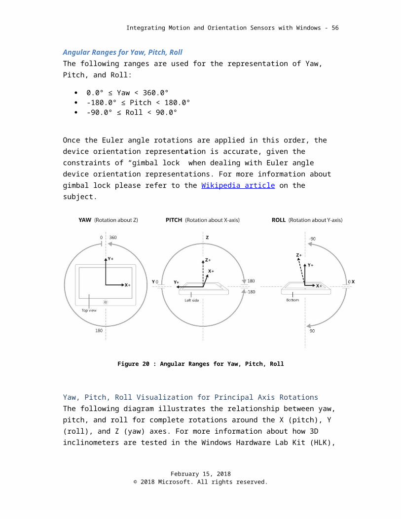
Angular Ranges for Yaw, Pitch, RollThe following ranges are used for the representation of Yaw, Pitch, and Roll:
0.0° ≤ Yaw < 360.0° -180.0° ≤ Pitch < 180.0° -90.0° ≤ Roll < 90.0°
Once the Euler angle rotations are applied in this order, the device orientation representation is accurate, given the constraints of “gimbal lock” when dealing with Euler angle device orientation representations. For more information about gimbal lock please refer to the Wikipedia article on the subject.
February 15, 2018© 2018 Microsoft. All rights reserved.

Integrating Motion and Orientation Sensors with Windows - 43
Figure 20 : Angular Ranges for Yaw, Pitch, Roll
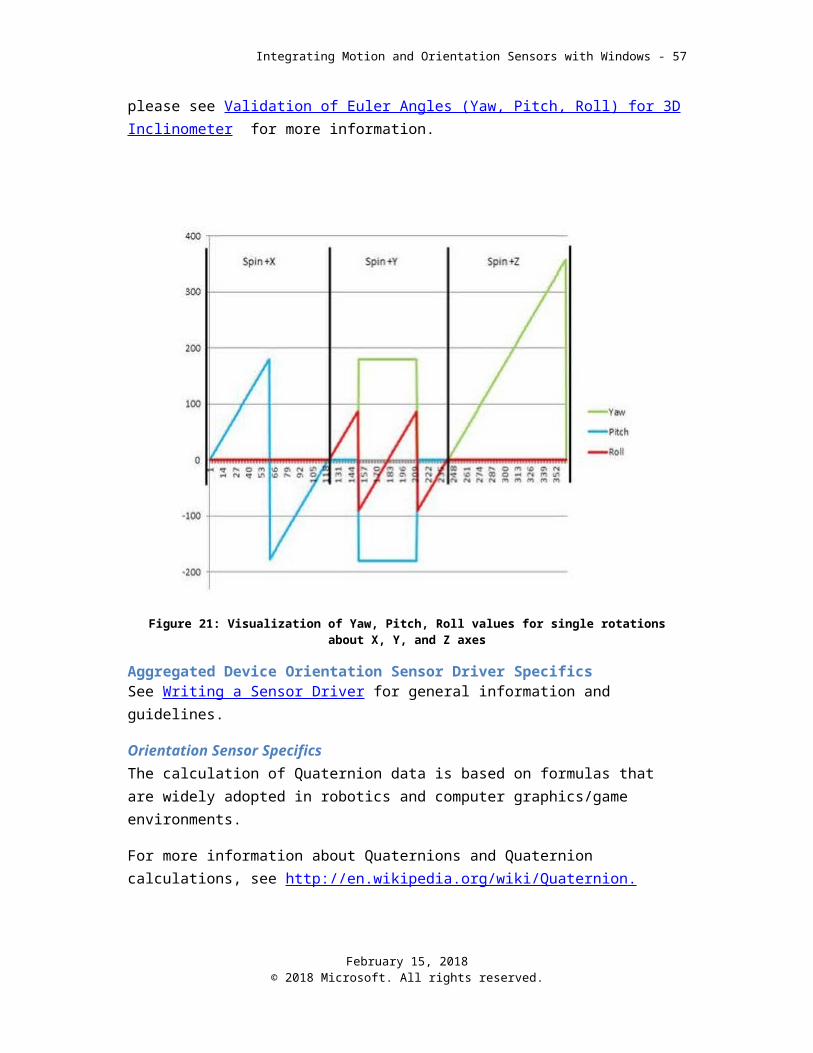
Yaw, Pitch, Roll Visualization for Principal Axis RotationsThe following diagram illustrates the relationship between yaw, pitch, and roll for complete rotations around the X (pitch), Y (roll), and Z (yaw) axes. For more information about how 3D inclinometers are tested in the Windows Hardware Lab Kit (HLK), please see Validation of Euler Angles (Yaw, Pitch, Roll) for 3D Inclinometer for more information.
February 15, 2018© 2018 Microsoft. All rights reserved.

Integrating Motion and Orientation Sensors with Windows - 44
Figure 21: Visualization of Yaw, Pitch, Roll values for single rotations about X, Y, and Z axes
Aggregated Device Orientation Sensor Driver SpecificsSee Writing a Sensor Driver for general information and guidelines.
Orientation Sensor SpecificsThe calculation of Quaternion data is based on formulas that are widely adopted in robotics and computer graphics/game environments.
For more information about Quaternions and Quaternion calculations, see http://en.wikipedia.org/wiki/Quaternion .
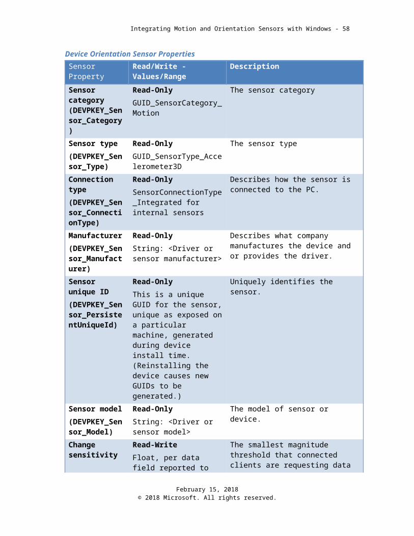
Device Orientation Sensor Properties
Sensor Property Read/Write - Values/Range Description
Sensor category (DEVPKEY_Sensor_Category)
Read-OnlyGUID_SensorCategory_Motion
The sensor category
Sensor type(DEVPKEY_Sensor_Type)
Read-OnlyGUID_SensorType_Accelerometer3D
The sensor type
Connection type(DEVPKEY_Sensor
Read-OnlySensorConnectionType_Integ
Describes how the sensor is connected to the PC.
February 15, 2018© 2018 Microsoft. All rights reserved.
Integrating Motion and Orientation Sensors with Windows - 45
_ConnectionType) rated for internal sensors
Manufacturer(DEVPKEY_Sensor_Manufacturer)
Read-OnlyString: <Driver or sensor manufacturer>
Describes what company manufactures the device and or provides the driver.
Sensor unique ID(DEVPKEY_Sensor_PersistentUniqueId)
Read-OnlyThis is a unique GUID for the sensor, unique as exposed on a particular machine, generated during device install time. (Reinstalling the device causes new GUIDs to be generated.)
Uniquely identifies the sensor.
Sensor model(DEVPKEY_Sensor_Model)
Read-OnlyString: <Driver or sensor model>
The model of sensor or device.
Change sensitivity Read-WriteFloat, per data field reported to the sensor class extension through EvtSensorGetDataThresholds
The smallest magnitude threshold that connected clients are requesting data for (or default, if no client has set this property).
This value is used by the driver to determine when a meaningful change in acceleration is detected.
Current report interval
Read-WriteInteger (milliseconds) reported to the sensor class extension through EvtSensorGetDataInterval
The fastest interval (expressed as the period between events) at which connected clients are requesting data (or default, if no client as set this property).
Device Orientation Sensor Data FieldsSensor Data Field Description
PKEY_SensorData_QuaternionX The x value of a quaternion representing the orientation of the device in 3D space. (VT_R4)
PKEY_SensorData_QuaternionY The y value of a quaternion representing the orientation of the device in 3D space. (VT_R4)
PKEY_SensorData_QuaternionZ The z value of a quaternion representing the orientation of the device in 3D space. (VT_R4)
PKEY_SensorData_QuaternionW The w value of a quaternion representing the orientation of the device in 3D space. (VT_R4)
The W value of a quaternion is limited to [0,1] instead of the full [-1, 1].
February 15, 2018© 2018 Microsoft. All rights reserved.

Integrating Motion and Orientation Sensors with Windows - 46
All rotations must be stated in the forward direction (and not the reverse).
Note: The output of quaternion should be in normalized format. When quaternions are expressed in normalized format, the values will satisfy the following:
√ x2+ y2+z2+w2=1.0Aggregated Device Orientation Sensor EventsN/A
Validation of an Orientation sensor ImplementationIn order to validate that an orientation sensor is properly integrated and that all sensors required for an orientation sensor are properly integrated/installed, the following simple tests should be performed. In some cases the Sensor Diagnostic Tool needs to be used.
Use the Sensor Diagnostic Tool to examine the 3D inclinometer and aggregated device orientation sensor under test. Expand the sensors and click on the 3D Inclinometer and then the Aggregated Device Orientation sensor. Validate that you see data updates. For a slate PC, perform the following data integrity checks:
See Validation of Euler Angles (Yaw, Pitch, Roll) for 3D Inclinometer .
9-Axis Data Accuracy GuidelinesThe following table indicates the goals for data output accuracy 9-axis motion and orientation implementations on Windows 10. Some of these guidelines are requirements, and some are suggestions based on the corresponding application and system-level features and scenarios.
Sensor Data field(s) Accuracy Goal (General)
HLK Accuracy Requirement
Notes
3D Accelerometer
X,Y,Z (G) +/- 5 mg (0.005 G)
- HLK tests cover rotation scenarios
3D Gyroscope X,Y,Z (DPS) 5 degrees/second
-
Compass Magnetic Heading, True North Heading*
+/-10 degrees +/-10 degrees
*If implemented (only magnetic North required)
Inclinometer Yaw, Pitch, Roll +/- 5 degrees* - *+/- 10 degrees accuracy allowed on heading axis
Device Quaternion +/- 5 degrees* ** - *Actual
February 15, 2018© 2018 Microsoft. All rights reserved.

Integrating Motion and Orientation Sensors with Windows - 47
Orientation quaternion vector should deviate no more than +/- 5 degrees from expected quaternion vector (tolerance compared against angle formed between quaternion vectors)
**+/- 10 degrees accuracy allowed on heading axis direction
Device Orientation
Rotation Matrix +/- 5 degrees* ** - *Rotation matrix values are converted to quaternion values for accuracy validation. The calculated quaternion vector should deviate no more than +/- 5 degrees from expected quaternion vector (tolerance compared against angle formed between quaternion vectors)
**+/- 10
February 15, 2018© 2018 Microsoft. All rights reserved.

Integrating Motion and Orientation Sensors with Windows - 48
degrees accuracy allowed on heading axis direction
February 15, 2018© 2018 Microsoft. All rights reserved.

Integrating Motion and Orientation Sensors with Windows - 49
Hardware Integration Options and Guidelines
Mechanical and Electrical Engineering ConsiderationsWhen integrating motion and orientation sensors into PC hardware, please consult with the IHV partners who supply sensor parts for primary guidance regarding how to properly integrate these components.
General concepts for motion sensor integration:
1. Locate motion sensing sensor components as close to the geometric center of the device as possible.
2. Place Magnetometer sensors as far away as possible from magnets (Hall Effect sensors or other magnetic components) and other sources of electromagnetic fields or interference (see Mechanical and Electromagnetic Considerations for Magnetometer).
3. Mount sensors on a plane that is parallel to the primary plane of the chassis (for example, mount an accelerometer on a plane that is parallel to the plane of the motherboard).
Mechanical and Electromagnetic Considerations for MagnetometerThe following list of specific considerations should be evaluated when performing system design activities related to magnetometer hardware:
System casing and mainboard (hard iron and soft iron proximity)o Cover: Avoid use of metals that are high in ferromagnetic materials (Fe, Co,
Ni). o Screws: Avoid use of metals that are high in ferromagnetic materials (Fe, Co,
Ni). Power
o Power lines: Avoid use of power lines within 1cm of compass circuitry (10mA+). For circuitry with larger current values, more space is required between traces/wires and magnetometer.
o Power reservoirs: Avoid use of power capacitors/inductors and ferrite beads within 10mm of compass circuitry.
o Battery: Besides checking current, keep battery connector far from sensor in case it contains ferromagnetic materials.
o High-Frequency Signals: Avoid high-frequency signal lines in close proximity of the magnetometer as this can impose interference for the magnetometer.
Antenna Placement: Avoid any wireless antenna placement within 1cm of the compass circuitry.
LCD Back-panel: Avoid use metals that are high in ferromagnetic materials (Fe, Co, Ni).
February 15, 2018© 2018 Microsoft. All rights reserved.

Integrating Motion and Orientation Sensors with Windows - 50
Component-Level Integration OptionsThere are an infinite number of ways to hook up sensors to system buses, MCU devices, etc. This section examines a few different ways that motion and orientation sensors can be “wired up” to PC controllers and buses, and also discusses the pros and cons for each approach.
Sensor Sub-Processor (MCU) Decision WorkflowThere are two primary ways in which motion/orientation sensor systems can be integrated with PC hardware running Windows 10:
1. Sensor driver approach2. HID firmware in device or MCU
Each of these approaches has pros and cons. The following table outlines these tradeoffs.
Sensor Driver HID Sensor Class DriverDriver Development Must write UMDF driver or
multiple drivers that communicate directly with sensor hardware, perform sensor fusion, integrate with Windows sensor platform
No driver work required
Device Validation Tests
IHV must pass HLK validation (run device validation tests)
Not required
System Validation Tests
Must pass system validation tests (system validation tests run by OEM)
Must pass system validation tests (system validation tests run by OEM)
Power Likely to consume more power Likely to save power
Performance Consumes measureable CPU bandwidth
Consumes minimal CPU bandwidth
Hardware cost Minimal MCU adds to system cost (BOM for PC)
Sensor Part Dependencies
Specific to particular hardware components - requires updated drivers to swap out sensor components
Requires only minor firmware changes in order to swap out sensor components
February 15, 2018© 2018 Microsoft. All rights reserved.

Integrating Motion and Orientation Sensors with Windows - 51
Connectivity OptionsThe following sections outline some of the possibilities for sensor part connectivity for Windows 10 systems. Please note that in addition to the busses shown here (USB and I2C), there are other options and buses that can also be used for connecting sensors.
9-Axis Combo Chip with Onboard Integration/Fusion
Figure 22: Example 9-Axis Motion/Orientation Sensor Part Connectivity (raw data sensor hardware shown here)
Using this connectivity approach, this system will be fully supported by the in-box Windows 10 HID sensor class driver if the device firmware is properly written.
Please see Leveraging in-box Driver Support for more details regarding the sensor software stack for this type of hardware connectivity.
February 15, 2018© 2018 Microsoft. All rights reserved.

Integrating Motion and Orientation Sensors with Windows - 52
Individual Components with Sensor Sub-Processor Integration/Fusion
Figure 23: Example Sub-Processor Motion/Orientation Sensor Part Connectivity (raw data sensor hardware shown here)
Using this connectivity approach, this system will be fully supported by the in-box Windows 10 HID sensor class driver if the device firmware is properly written.
Please see Leveraging in-box Driver Support for more details regarding the sensor software stack for this type of hardware connectivity.
February 15, 2018© 2018 Microsoft. All rights reserved.
Integrating Motion and Orientation Sensors with Windows - 53
Individual Components with Driver-Level Integration/Fusion
Figure 24: Example Individual Motion/Orientation Sensor Part Connectivity
Third-Party Motion Orientation Driver ComponentsThere are many different ways that sensor drivers for motion/orientation can be supported.
The following illustration shows one driver stack for a single third-party driver (actually two drivers) that can be implemented to support motion/orientation sensors connected over simple peripheral buses. In some cases multiple sensor drivers would be written, but in this case, a single driver communicates with all sensors and performs sensor fusion.
February 15, 2018© 2018 Microsoft. All rights reserved.

Integrating Motion and Orientation Sensors with Windows - 54
Figure 25: Example driver stack for I2C connected motion/orientation sensors (Blue boxes in-box for Windows 10, sensor fusion performed in UMDF sensor driver in this case)
For more information, please see Writing a Sensor Driver .
February 15, 2018© 2018 Microsoft. All rights reserved.

Integrating Motion and Orientation Sensors with Windows - 55
Leveraging In-box Driver SupportWindows 10 provides an in-box sensor driver for HID-connected sensor devices. In addition, Windows 10 also provides a driver for HID over I2C for devices that are I2C-connected that implement HID support for sensors. The following diagrams demonstrate how these types of systems should be implemented and which components are required (in-box and third-party) in order to take advantage of the in-box HID sensor class driver.
The in-box HID sensor class driver implements much of the logic described in Writing a Sensor Driver including client tracking for the Report Interval and the Change Sensitivity (a.k.a. threshold). These values are evaluated each time client state changes, and these filtering criteria are passed via HID to the device firmware that allows for advanced power management (powering down individual sensors when not needed, controlling data rates, etc.) at a low level. The HID sensor class driver therefore acts as both a client monitor and a pass-through mechanism, forwarding data and other events when raised in the device firmware.
February 15, 2018© 2018 Microsoft. All rights reserved.
Integrating Motion and Orientation Sensors with Windows - 56
Figure 26: Example of device that uses in-box HID sensor class driver (Blue boxes in-box for Windows 10)
This diagram shows an example of a device that implements firmware-level support for HID sensors, and therefore leverages the in-box HID sensor class driver.
February 15, 2018© 2018 Microsoft. All rights reserved.
Integrating Motion and Orientation Sensors with Windows - 57
Figure 27: Example of device that uses Windows HID sensor class driver (I2C connected in this case - Blue boxes in-box for Windows)
February 15, 2018© 2018 Microsoft. All rights reserved.
Integrating Motion and Orientation Sensors with Windows - 58
Writing a Sensor DriverThe best place to start for conceptual information when writing a Windows sensor driver is the Sensor Devices topics in the Windows Driver Kit.
Another source of invaluable information for sensor driver developers is the WDK (Windows Driver Kit) samples for sensor drivers:
ADXL345Acc sensor driver sample Fusion sensor driver sample Gyroscope and Magnetometer combo driver sample
These samples can serve as a starting point for your driver. Please refer to the WDK sample documentation for more details.
After you have become familiar with the basic concepts of writing a sensor driver and have reviewed the WDK sensor driver samples, please use the following guidelines to ensure your motion/orientation sensor driver is optimized for Windows.
Proper Support for Time and Magnitude Thresholds (Filtering Criteria)In order to optimize data throughput/traffic for sensors, filtering criteria must be used to “throttle” data updated events so that they are raised only when needed by applications. This results in better system performance (less CPU utilization due to sensor throughput) and less power consumption (sensor part and CPU power).
Terminologies Related To Filtering CriteriaTerm Meaning:Report Interval (RI) The rate expressed as the period (not
frequency) in milliseconds at which a client wishes to receive data updates when meaningful change in magnitude is occurring.
This field is expressed as the minimum period between events if meaningful change has occurred (in measured sensor phenomenon). The period will vary but never be shorter than this, based on the occurrence of meaningful change.
This value is per sensor.Change Sensitivity (CS) The change in measured phenomenon that
constitutes a meaningful change. This can be expressed as linear magnitude (for example, .05 G for an accelerometer reading) or as a non-linear magnitude (5% for an ambient light sensor reading).
February 15, 2018© 2018 Microsoft. All rights reserved.

Integrating Motion and Orientation Sensors with Windows - 59
This value is per sensor data field.Effective Current Report Interval (E-RI) The RI value calculated at any given point in
time and used by the device driver to filter data update event delivery based on:
RI values set by clients (if any) The default RI for the device (as
implemented by driver as default behavior)
The ability of the hardware to respect the requested RI
This value is per sensor.Effective Change Sensitivity (E-CS) The CS value calculated at any given point in
time and used by the device driver to filter data update event delivery based on:
CS values set by clients (if any) The default CS for the device (as
implemented by driver as default behavior)
The ability of the hardware to respect the requested CS
This value is per sensor data field.
Events of InterestThe following events should be monitored and should initiate the evaluation of the current effective RI and CS values.
For each client being tracked, the following data should be stored.
Client container item fields:
Per sensoro Client file pointer (identifies client) o RI values
Per sensor data fieldo CS values (one per data field)
Event of interest Event handler activitiesEvtSensorStart Starts the sensorEvtSensorStop Stops the sensorEvtSensorSetDataInterval Sets the report intervalEvtSensorSetDataThresholds Sets the sensor data change
sensitivity (CS)SensorsCxSensorDataReady The driver reports a sample
to the sensors class
February 15, 2018© 2018 Microsoft. All rights reserved.
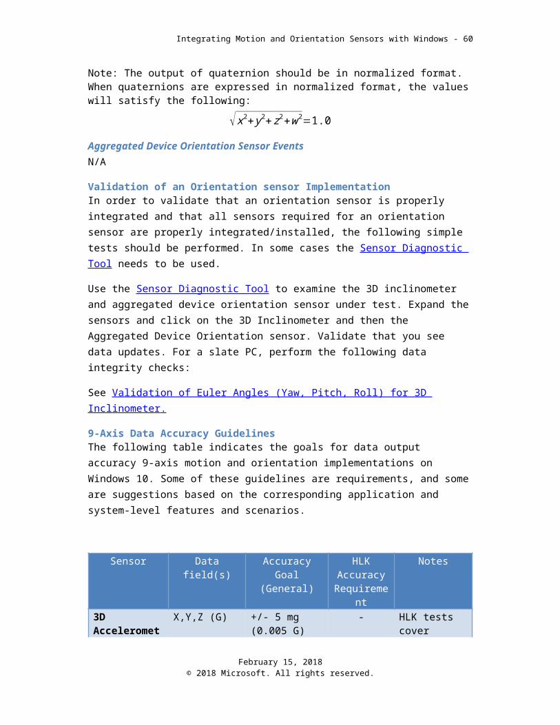
Integrating Motion and Orientation Sensors with Windows - 60
extension
Example: 3D accelerometer container representing four connected clients (table is container, each row is a container item, and each cell with a value is a container item field). The default values are used for a particular value when no client currently has set a value for CS/RI value in question.
Client File Handle RI CS (X) CS (Y) CS (Z)Defaults 100 0.02 0.02 0.02
FF80A267 0 0.001 0.001 0.001FF802489 70 0.02 0.02 0.02FF80D345 15 NULL NULL NULLFF803287 100 0.005 0.005 0.005
After evaluation of this set of connected clients, the following values are used:
E-RI: 15ms E-CS values: (could collapse to single value using smallest threshold)
o X: .001o Y: .001o Z: .001
Default Values for CS and RI for Motion SensorsIf no application clients have set the CS or RI properties, default values should be used. The following table outlines the values that should be used by default by a driver supporting motion/orientation sensors.
Hardware Current Report Interval
Change Sensitivity
Accelerometer 100ms 0.02 G (X,Y,Z)
Gyro 100ms 0.5 DPS (X,Y,Z)Compass 100ms 0.2 Degrees (magnetic north and true
north)Inclinometer 50ms 0.5 Degrees (X,Y,Z)
Device Orientation 50ms 0.5 Degrees (X,Y,Z)
Change Sensitivity (CS, a.k.a. thresholds) for the Orientation SensorChange sensitivity for the orientation sensor should be calculated as the angle between two quaternions. Mathematically, this is expressed as:
February 15, 2018© 2018 Microsoft. All rights reserved.

Integrating Motion and Orientation Sensors with Windows - 61
2*cos-1 (dot product(q1, q2))
This calculation ensures consistency across various tablet (or device) orientations.
Filtering Data Update Events by Evaluating Effective report interval and change sensitivity values (E-RI, E-CS)Once the current E-RI and E-CS values have been determined (and are updated as sensor connection states change or when RI/CS properties are set by clients), these values can be used to throttle/filter events that are raised to connected client applications.
There is a basic principle for filtering events using both the current E-RI and current E-CS values as filtering criteria for events that will be raised. These filtering values are compared against the difference between the current data values and the previous data values in order to determine when events should be raised. If the magnitude thresholds (E-CS) have been exceeded for a time period equal to or greater than the time threshold (E-RI), then and only then should a data event be raised. It is recommended to raise a data event on driver startup when the initial values have been obtained so that clients can receive the proper notification. In addition this implementation should not wake up the CPU more often than the requested report interval, to conserve power.
The following diagram demonstrates how time filtering of raw sensor data is evaluated in order to determine when data events should be raised.
Here, the red data in the lower portion of the diagram represents the raw sensor data. The green line represents data that would be returned to clients that poll for data (one of many
February 15, 2018© 2018 Microsoft. All rights reserved.

Integrating Motion and Orientation Sensors with Windows - 62
ways to implement this behavior) and the “X” values represent when data events are fired. Blue lines are the thresholds for the E-CS boundaries (+/- E-CS relative to last data event value).
By implementing this event filtering logic, the number of data updated events can be greatly reduced, and applications can still get notified when meaningful changes in sensor data occur.
Initial sample readingWhen a sensor driver is started through a call to EvtSensorStart, the driver must report one sensor sample through a call to SensorsCxSensorDataReady as soon as the sensor hardware is ready to send valid data. The initial sample reading must be sent to the class extension irrespective of the report interval or change sensitivity settings. Application use the initial sample as basis for data comparison.
Power Management Best-PracticesPower management is a key aspect of optimizing sensor implementations on portable PCs such as slate PCs. Here are some general guidelines for power management of sensors:
1. Power down individual sensors when they are not needed (see table below). This is detected based on the connected client count for each sensor. One or more connected clients means that the sensor is in use; zero (0) connected clients means sensors can be powered down.
2. When on, actively manage power state, duty cycle, and reporting interval to minimize power consumption (while satisfying application preferences for data rates and filtering).
The following table shows individual component sensor power state based on the presence of a connected client for a particular type of sensor.
Sensors objects in Sensors API: At least one client connectedHardware: Accelerometer Gyro Inclinometer Compass Device Orientation
Accelerometer On Off On On OnGyro Off On On On On
Magnetometer Off Off On On On
Note: This power management also applies to device firmware (not just driver development) if an MCU is used for sensor fusion.
February 15, 2018© 2018 Microsoft. All rights reserved.

Integrating Motion and Orientation Sensors with Windows - 63
Testing and Validation For Windows 10, the Sensor Diagnostic Tool (available with the WDK) allows the user to view what sensors are present on a particular system and monitor sensor data, properties, and events. This tool can be used to log sensor data to a CSV file as well, which can be useful for data integrity checks and diagnostics.
Sensor Diagnostic Tool
For more information about this tool, please see the WDK documentation.
February 15, 2018© 2018 Microsoft. All rights reserved.
Integrating Motion and Orientation Sensors with Windows - 64
CalibrationThere are two main classes of sensor calibration: per-model calibration and per-system calibration
Per-Model CalibrationPer-model calibration corresponds to the corrections and tuning that are performed for a sensor or sensor system on a per model (PC SKU basis). This calibration can account for the electromagnetic characteristics of the chassis (for the magnetometer for hardware or compass algorithm for software/firmware), and also some offset calibration and sensitivity calibration. Every effort should be taken to gather data on a per-system basis and correct/calibrate as much as possible on a per-system level in order to minimize or eliminate the per-system calibration requirements and activities.
Per-System CalibrationIn some cases it may be required to calibrate systems on a per-unit basis at the production facility. This should be avoided if possible in order to decrease the time and space requirements during production.
For more information about per-model calibration versus per-system calibration, please consult with the IHV partners supplying motion and orientation sensors and software.
End-User Calibration and Continuous Auto-CalibrationThis section covers calibration activities and mechanisms that are optionally employed after the factory production process.
Preferred: Continuous Auto-CalibrationIf possible, calibration and interference compensation should occur in device firmware or driver code in such a way that optimal calibration can be adjusted in real-time if adjustment or calibration is required after the factory production process. The specifics of these mechanisms are beyond the scope of this paper.
Not Preferred: End User CalibrationIn some cases, calibration of sensors requires the user to move the device in a particular way. Windows 10 does not provide support (APIs or user interface) for this scenario. If end-user calibration is required, the trigger and user interface need to be implemented by the IHV or OEM.
InquiriesSensor-related inquiries: [email protected]
February 15, 2018© 2018 Microsoft. All rights reserved.

Integrating Motion and Orientation Sensors with Windows - 65
Appendix
Accelerometer Measurement ConventionsAccelerometers are transducers that convert mechanical force into a signal that is proportional to the magnitude of the force being measured.
Force and AccelerationBefore getting into any specifics regarding accelerometer technology or guidelines for integrating accelerometer hardware into Windows PC hardware, it is important to first cover the principles of physics. This will result in an accurate and consistent conceptual representation of these devices and a consistent nomenclature.
Perhaps the most important set of observations regarding force, mass, and acceleration were stated by Sir Isaac Newton in his first, second, and third laws of motion (paraphrased here):
1. An object in motion will tend to stay in motion unless an external force is applied.2. The relationship between mass (M), Force (F), and acceleration (A) can be expressed
in relation to each other by the following equation: F = M*A3. For every action, there is an equal and opposite reaction
In the remainder of this paper, these principles listed are referred to as Newton’s first, second, and third laws, respectively.
Theory of Accelerometer MechanicsIn order to understand a simplified representation of an accelerometer, first consider an object that is sitting at rest on a flat surface.
Objects in Static Equilibrium
February 15, 2018© 2018 Microsoft. All rights reserved.

Integrating Motion and Orientation Sensors with Windows - 66
Figure 28: Object at rest on flat level surface (side view)
In this diagram, F1 is the force due to gravity (pointing towards the center of the earth), and F2 is the ground reaction force acting in a direction away from the center of the earth. These forces are equal in magnitude (since the object is in static equilibrium) and opposite in direction.
Now, take a look at the mechanical analog of a single axis (measuring acceleration in only one direction) accelerometer. While this representation typically consists of a damped mass on a spring, we’ll omit the damper since it is not applicable to the conversation.
Figure 29: Simple accelerometer analogy: mass suspended by a spring (side view)
Assume that the entire assembly is at rest, you then know that F1 (force due to gravity) is of the same magnitude as F2 (ground reaction force). You also know that the spring is deflected by some distance (δ in the above diagram). The accelerometer would in turn generate a signal that is proportional to the deflection of the spring, and convert that signal into a measurement of acceleration.
February 15, 2018© 2018 Microsoft. All rights reserved.

Integrating Motion and Orientation Sensors with Windows - 67
The accelerometer can be configured to output a signal that is proportional to and in the same direction as either F1 (force due to gravity) or F2 (the ground reaction force). This is a matter of convention.
Accelerometers exposed via the Windows Sensor and Location Platform expose acceleration values that are proportional to and in the same direction as the force due to gravity**
**F1 in the above diagrams, the BLUE arrow
Interactions with Gravity and External ForcesNow that we’ve covered the acceleration measurement convention, let’s examine some common interactions that we can use to illustrate what acceleration sensor data will look like for common scenarios.
Scenario 1: 1D Accelerometer pointed towards the center of the earth
February 15, 2018© 2018 Microsoft. All rights reserved.

Integrating Motion and Orientation Sensors with Windows - 68
Figure 30: Force due to gravity acting on accelerometer (side view)
In this diagram, the single-axis (1D) accelerometer is pointed towards the center of the earth, and the resultant acceleration measurement is +1.0G (+9.8 m/s2 or +32.2 ft/s2, depending on the units and convention used). In this document, acceleration is measured in G (relative to the gravitational constant). Here the blue arrow is the force of gravity acting on the accelerometer.
Using the Windows acceleration measurement convention, if you point the + axis of an accelerometer towards the center of the earth, you will register a positive acceleration along the corresponding accelerometer axis.
Scenario 2: Applying a force to the accelerometerAccording to Newton’s third law, every action has an equal and opposite reaction. If you apply a force to the accelerometer assembly (shown here as a mass hanging from a spring suspended in a frame), the reaction of the accelerometer is equal and opposite. As in the other scenarios, the reaction of the accelerometer is modeled as a deflection of the spring.
February 15, 2018© 2018 Microsoft. All rights reserved.

Integrating Motion and Orientation Sensors with Windows - 69
Consider the accelerometer lying on a flat level surface with an external force applied, as shown in this diagram.
Figure 31: External force acting on accelerometer (top view)
Here we have an external force applied to the accelerometer (such as a person pushing on the accelerometer enclosure) represented by F1 (green arrow). Think of this force as the action. There is also a reaction, which is the spring extending to do the inertia of the mass suspended by the spring. The resultant acceleration measurement (F2, blue arrow) is proportional to the external force (F1, green arrow) but opposite in magnitude. Based on the orientation of the + and – axes for this accelerometer, the resultant acceleration is negative. At first, this may not seem intuitive, but if you think of the measurement corresponding to the direction of the extension of the spring in this diagram, this concept becomes clearer.
Using the Windows acceleration measurement convention, if you apply an external force to an accelerometer, the measured acceleration will be in the opposite direction (opposite sign) compared to the direction of the force applied to the accelerometer.
February 15, 2018© 2018 Microsoft. All rights reserved.

Integrating Motion and Orientation Sensors with Windows - 70
Validation of Euler Angles (Yaw, Pitch, Roll) for 3D Inclinometer
Yaw Tests Overview
X (Pitch) Y (Roll) Z (Yaw)Test Yaw Min Max Min Max Min Max
1 0 -10 10 -10 10 [0 to 10] [350 to 360]
2 90 -10 10 -10 10 80 100
3 180 -10 10 -10 10 170 190
4 270 -10 10 -10 10 260 280
Test Steps for Yaw
Figure 32: Yaw Test 1 – Yaw = 0°
February 15, 2018© 2018 Microsoft. All rights reserved.

Integrating Motion and Orientation Sensors with Windows - 71
Figure 33: Yaw Test 2 – Yaw = 90°
Figure 34: Yaw Test 3 – Yaw = 180°
February 15, 2018© 2018 Microsoft. All rights reserved.

Integrating Motion and Orientation Sensors with Windows - 72
Figure 35: Yaw Test 4 – Yaw = 270°
Pitch Tests Overview
X (Pitch) Y (Roll) Z (Yaw)Test Pitch Min Max Min Max Min Max
1 0 -10 10 -10 10 [0 to 10] [350 - 360]
2 90 80 100 -10 10 [0 to 10] [350 - 360]
3 180 [-180 to -170] [170 to 180] -10 10 [0 to 10] [350 - 360]
4 270 -100 -80 -10 10 [0 to 10] [350 - 360]
Pitch Test Steps
Figure 36: Pitch Test 1 – Pitch = 0°
February 15, 2018© 2018 Microsoft. All rights reserved.

Integrating Motion and Orientation Sensors with Windows - 73
Figure 37: Pitch Test 2 – Pitch = 90°
Figure 38: Pitch Test 3 – Pitch = 180°
February 15, 2018© 2018 Microsoft. All rights reserved.

Integrating Motion and Orientation Sensors with Windows - 74
Figure 38: Pitch Test 4 – Pitch = 270°
Roll Tests OverviewX (Pitch) Y (Roll) Z (Yaw)
Test Roll Min Max Min Max Min Max
1 0 -10 10 -10 10 [0 to 10][350 - 360]
2a1* 90 -10 10 80 90 [0 to 10][350 - 360]
2b1* 90 [-180 to -170] [170 to 180] -90 -80 170 1903 180 [-180 to -170] [170 to 180] -10 10 170 190
4a2* 270 -10 10 -90 -80 [0 to 10][350 - 360]
4b2* 270 [-180 to -170] [170 to 180] 80 90 170 190
*Note: The tests shown in gray represent problematic test angles where multiple discontinuities for Euler angle data create unique validation challenges. These specific values are not validated in Windows HLK tests due to these problematic phenomena.
February 15, 2018© 2018 Microsoft. All rights reserved.

Integrating Motion and Orientation Sensors with Windows - 75
Roll Test Steps
Figure 40: Roll Test 1 – Roll = 0°
Figure 41: Roll Test 2 – Roll = 90°
February 15, 2018© 2018 Microsoft. All rights reserved.

Integrating Motion and Orientation Sensors with Windows - 76
Figure 42: Roll Test 3 – Roll = 180°
Figure 43: Roll Test 4 – Roll = 270°
February 15, 2018© 2018 Microsoft. All rights reserved.

Integrating Motion and Orientation Sensors with Windows - 77
Expected quaternion values for Euler angle rotationsPlease reference rotations for yaw, pitch, and roll from the Euler angle tests section.
Yaw Rotations
Test Angle (Yaw) X Y Z W
Expected Rotation Matrix
1 0 0 0 0 1
1 0 0
0 1 0
0 0 1
2 90 0 0 1/√2 1/√2
0 -1 0
1 0 0
0 0 1
3 180 0 0 -1 0
-1 0 0
0 -1 0
0 0 1
4 270 0 0 -1/√2 1/√2
0 1 0
-1 0 0
0 0 1
Pitch Rotations
Test Angle (Pitch) X Y Z W R
1 0 0 0 0 1
1 0 0
0 1 0
0 0 1
2 90 1/√2 0 0 1/√2 1 0 0
0 0 -1
February 15, 2018© 2018 Microsoft. All rights reserved.

Integrating Motion and Orientation Sensors with Windows - 78
0 1 0
3 180 -1 0 0 0
1 0 0
0 -1 0
0 0 -1
4 270 -1/√2 0 0 1/√2
1 0 0
0 0 1
0 -1 0
Roll Rotations
Test Angle (Roll) X Y Z W R
1 0 0 0 0 1
1 0 0
0 1 0
0 0 1
2 90 0 1/√2 0 1/√2
0 0 1
0 1 0
-1 0 0
3 180 0 -1 0 0
-1 0 0
0 1 0
0 0 -1
4 270 0 - 1/√2 0 1/√2
0 0 -1
0 1 0
1 0 0
Note that there is a discontinuity at 180 degree rotations where the axis is inverted, so the value of the rotation axis component skips from +1 to -1.
February 15, 2018© 2018 Microsoft. All rights reserved.

Integrating Motion and Orientation Sensors with Windows - 79
The W value of a quaternion is limited to [0,1] instead of the full [-1, 1].
All rotations must be stated in the forward direction (and not the reverse).
February 15, 2018© 2018 Microsoft. All rights reserved.

Integrating Motion and Orientation Sensors with Windows - 80
Expected values for Tilt-Compensated Compass HeadingPlease reference rotations for Yaw, Pitch, Roll from the Euler angle tests section
Yaw Rotations Test Angle (Yaw) Compass Heading1 0 0 (North)2 90 270 (West)3 180 180 (South)4 270 90 (East)
Pitch Rotations Test Angle (Pitch) Compass Heading1 0 0 (North)2 90 0 (North)3 180 180 (South)4 270 180 (South)
Roll Rotations Test Angle (Roll) Compass Heading1 0 0 (North)2 90 0 (North)3 180 0 (North)4 270 0 (North)
February 15, 2018© 2018 Microsoft. All rights reserved.