ote outotec fluidization technology eng web
DESCRIPTION
fluidised bed technologyTRANSCRIPT

Outotec® Fluidization technology
Innovative solutions for fine grained materials
n Calcination
n Roasting
n Reduction
n Gasification
n Combustion
n Decarbonization
n Oxidation
n Gas cleaning
n Heat recovery
n Cooling
n Drying
n Spray granulation
002 Fluidization technology
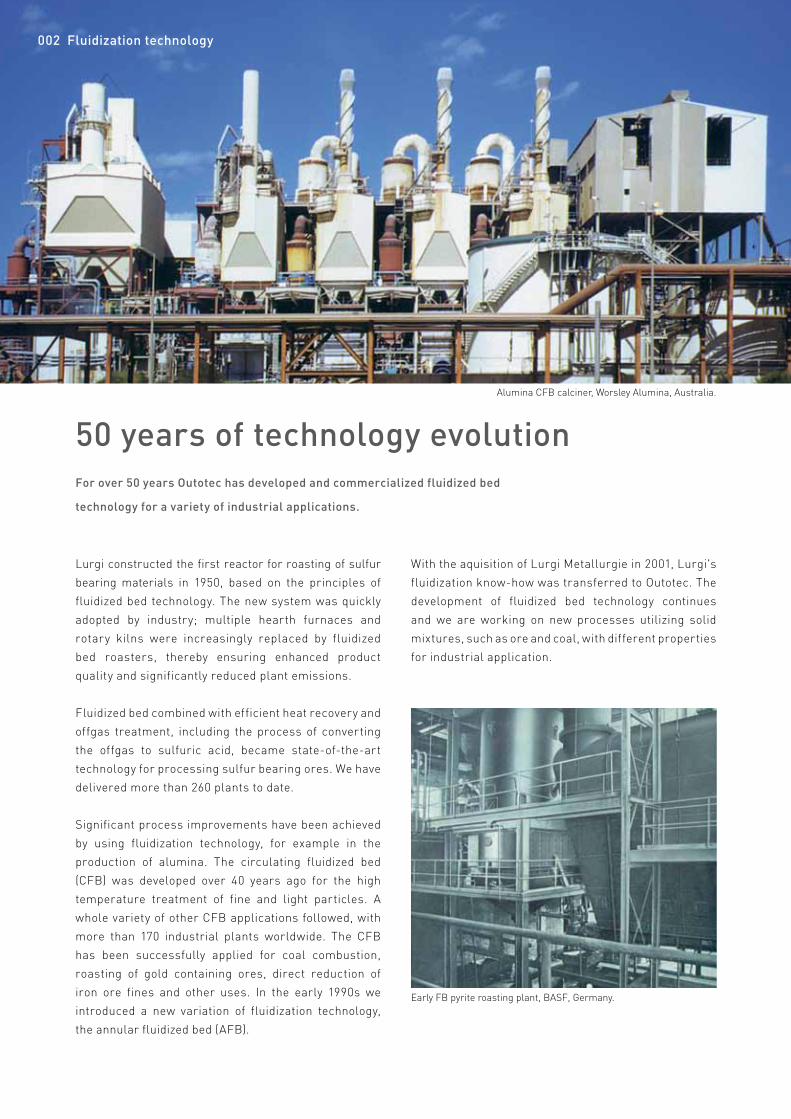
50 years of technology evolutionAlumina CFB calciner, Worsley Alumina, Australia.
Lurgi constructed the first reactor for roasting of sulfur bearing materials in 1950, based on the principles of fluidized bed technology. The new system was quickly adopted by industry; multiple hearth furnaces and rotary kilns were increasingly replaced by fluidized bed roasters, thereby ensuring enhanced product quality and significantly reduced plant emissions.
Fluidized bed combined with efficient heat recovery and offgas treatment, including the process of converting the offgas to sulfuric acid, became state-of-the-art technology for processing sulfur bearing ores. We have delivered more than 260 plants to date.
Significant process improvements have been achieved by using fluidization technology, for example in the production of alumina. The circulating fluidized bed (CFB) was developed over 40 years ago for the high temperature treatment of fine and light particles. A whole variety of other CFB applications followed, with more than 170 industrial plants worldwide. The CFB has been successfully applied for coal combustion, roasting of gold containing ores, direct reduction of iron ore fines and other uses. In the early 1990s we introduced a new variation of fluidization technology, the annular fluidized bed (AFB).
Early FB pyrite roasting plant, BASF, Germany.
For over 50 years Outotec has developed and commercialized fluidized bed
technology for a variety of industrial applications.
With the aquisition of Lurgi Metallurgie in 2001, Lurgi's fluidization know-how was transferred to Outotec. The development of fluidized bed technology continues and we are working on new processes utilizing solid mixtures, such as ore and coal, with different properties for industrial application.
Fluidization technology 003
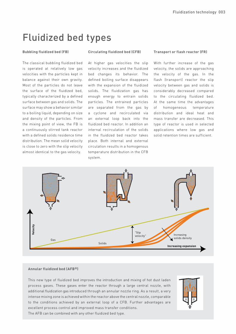
Fluidized bed typesBubbling fluidized bed (FB)
The classical bubbling fluidized bed is operated at relatively low gas velocities with the particles kept in balance against their own gravity. Most of the particles do not leave the surface of the fluidized bed, typically characterized by a defined surface between gas and solids. The surface may show a behavior similar to a boiling liquid, depending on size and density of the particles. From the mixing point of view, the FB is a continuously stirred tank reactor with a defined solids residence time distribution. The mean solid velocity is close to zero with the slip velocity almost identical to the gas velocity.
Circulating fluidized bed (CFB)
At higher gas velocities the slip velocity increases and the fluidized bed changes its behavior. The defined boiling surface disappears with the expansion of the fluidized solids. The fluidization gas has enough energy to entrain solids particles. The entrained particles are separated from the gas by a cyclone and recirculated via an external loop back into the fluidized bed reactor. In addition an internal recirculation of the solids in the fluidized bed reactor takes place. Both internal and external circulation results in a homogenous temperature distribution in the CFB system.
Transport or flash reactor (FR)
With further increase of the gas velocity, the solids are approaching the velocity of the gas. In the flash (transport) reactor the slip velocity between gas and solids is considerably decreased compared to the circulating fluidized bed. At the same time the advantages of homogeneous temperature distribution and ideal heat and mass transfer are decreased. This type of reactor is used in selected applications where low gas and solid retention times are sufficient.
Annular fluidized bed (AFB®)
This new type of fluidized bed improves the introduction and mixing of hot dust laden process gases. These gases enter the reactor through a large central nozzle, with additional fluidization gas introduced through an annular nozzle ring. As a result, a very intense mixing zone is achieved within the reactor above the central nozzle, comparable to the conditions achieved by an external loop of a CFB. Further advantages are excellent process control and improved mass transfer conditions.The AFB can be combined with any other fluidized bed type.
Bubbling fluidized bed
Increasing solids density
Increasing expansion
Gas
"Slipvelocity"
Solids
Velo
city
Transport reactorCirculating fluidized bed
004 Fluidization technology
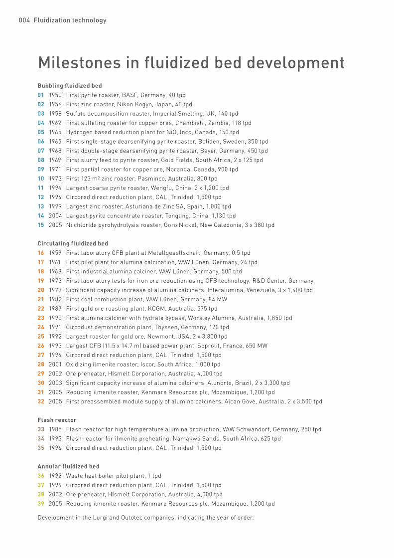
Bubbling fluidized bed 01 1950 First pyrite roaster, BASF, Germany, 40 tpd02 1956 First zinc roaster, Nikon Kogyo, Japan, 40 tpd03 1958 Sulfate decomposition roaster, Imperial Smelting, UK, 140 tpd04 1962 First sulfating roaster for copper ores, Chambishi, Zambia, 118 tpd05 1965 Hydrogen based reduction plant for NiO, Inco, Canada, 150 tpd06 1965 First single-stage dearsenifying pyrite roaster, Boliden, Sweden, 350 tpd07 1968 First double-stage dearsenifying pyrite roaster, Bayer, Germany, 450 tpd08 1969 First slurry feed to pyrite roaster, Gold Fields, South Africa, 2 x 125 tpd09 1971 First partial roaster for copper ore, Noranda, Canada, 900 tpd10 1973 First 123 m2 zinc roaster, Pasminco, Australia, 800 tpd11 1994 Largest coarse pyrite roaster, Wengfu, China, 2 x 1,200 tpd12 1996 Circored direct reduction plant, CAL, Trinidad, 1,500 tpd13 1999 Largest zinc roaster, Asturiana de Zinc SA, Spain, 1,000 tpd14 2004 Largest pyrite concentrate roaster, Tongling, China, 1,130 tpd15 2005 Ni chloride pyrohydrolysis roaster, Goro Nickel, New Caledonia, 3 x 380 tpd
Circulating fluidized bed16 1959 First laboratory CFB plant at Metallgesellschaft, Germany, 0.5 tpd17 1961 First pilot plant for alumina calcination, VAW Lünen, Germany, 24 tpd18 1968 First industrial alumina calciner, VAW Lünen, Germany, 500 tpd19 1973 First laboratory tests for iron ore reduction using CFB technology, R&D Center, Germany20 1979 Significant capacity increase of alumina calciners, Interalumina, Venezuela, 3 x 1,400 tpd21 1982 First coal combustion plant, VAW Lünen, Germany, 84 MW22 1987 First gold ore roasting plant, KCGM, Australia, 575 tpd23 1990 First alumina calciner with hydrate bypass, Worsley Alumina, Australia, 1,850 tpd24 1991 Circodust demonstration plant, Thyssen, Germany, 120 tpd25 1992 Largest roaster for gold ore, Newmont, USA, 2 x 3,800 tpd26 1993 Largest CFB (11.5 x 14.7 m) based power plant, Soprolif, France, 650 MW27 1996 Circored direct reduction plant, CAL, Trinidad, 1,500 tpd28 2001 Oxidizing ilmenite roaster, Iscor, South Africa, 1,000 tpd29 2002 Ore preheater, HIsmelt Corporation, Australia, 4,000 tpd30 2003 Significant capacity increase of alumina calciners, Alunorte, Brazil, 2 x 3,300 tpd 31 2005 Reducing ilmenite roaster, Kenmare Resources plc, Mozambique, 1,200 tpd32 2005 First preassembled module supply of alumina calciners, Alcan Gove, Australia, 2 x 3,500 tpd
Flash reactor33 1985 Flash reactor for high temperature alumina production, VAW Schwandorf, Germany, 250 tpd34 1993 Flash reactor for ilmenite preheating, Namakwa Sands, South Africa, 625 tpd35 1996 Circored direct reduction plant, CAL, Trinidad, 1,500 tpd
Annular fluidized bed36 1992 Waste heat boiler pilot plant, 1 tpd37 1996 Circored direct reduction plant, CAL, Trinidad, 1,500 tpd38 2002 Ore preheater, HIsmelt Corporation, Australia, 4,000 tpd39 2005 Reducing ilmenite roaster, Kenmare Resources plc, Mozambique, 1,200 tpd
Development in the Lurgi and Outotec companies, indicating the year of order.
Milestones in fluidized bed development
Fluidization technology 005
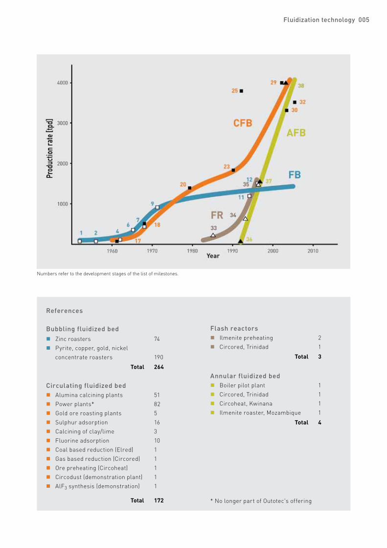
References
Bubbling fluidized bed n Zinc roasters 74 n Pyrite, copper, gold, nickel
concentrate roasters 190
Total 264
Circulating fluidized bed n Alumina calcining plants 51 n Power plants* 82 n Gold ore roasting plants 5 n Sulphur adsorption 16 n Calcining of clay/lime 3 n Fluorine adsorption 10 n Coal based reduction (Elred) 1 n Gas based reduction (Circored) 1 n Ore preheating (Circoheat) 1 n Circodust (demonstration plant) 1 n AlF3 synthesis (demonstration) 1
Total 172
Flash reactors n Ilmenite preheating 2 n Circored, Trinidad 1
Total 3
Annular fluidized bed n Boiler pilot plant 1 n Circored, Trinidad 1 n Circoheat, Kwinana 1 n Ilmenite roaster, Mozambique 1
Total 4
Numbers refer to the development stages of the list of milestones.
* No longer part of Outotec's offering
006 More out of ore!006 Fluidization technology
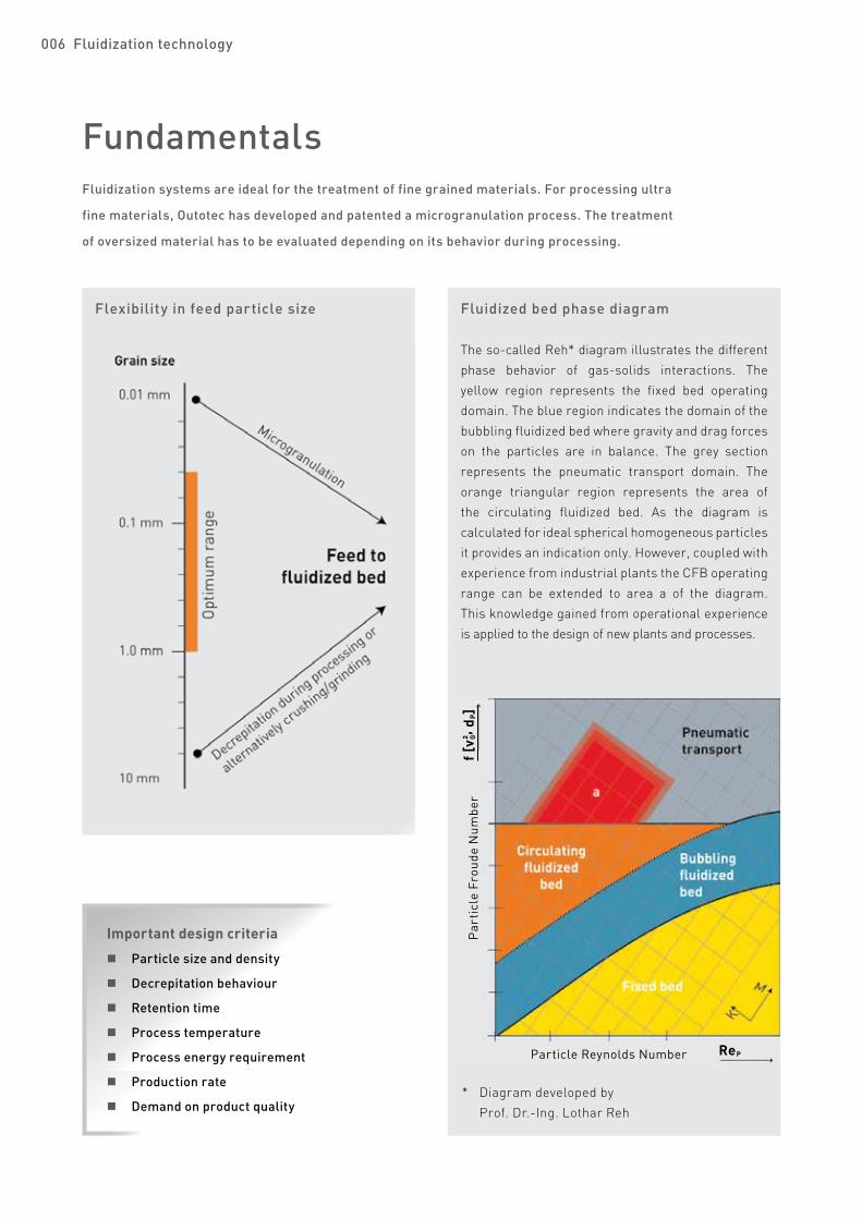
FundamentalsFluidization systems are ideal for the treatment of fine grained materials. For processing ultra
fine materials, Outotec has developed and patented a microgranulation process. The treatment
of oversized material has to be evaluated depending on its behavior during processing.
Fluidized bed phase diagram
The so-called Reh* diagram illustrates the different phase behavior of gas-solids interactions. The yellow region represents the fixed bed operating domain. The blue region indicates the domain of the bubbling fluidized bed where gravity and drag forces on the particles are in balance. The grey section represents the pneumatic transport domain. The orange triangular region represents the area of the circulating fluidized bed. As the diagram is calculated for ideal spherical homogeneous particles it provides an indication only. However, coupled with experience from industrial plants the CFB operating range can be extended to area a of the diagram. This knowledge gained from operational experience is applied to the design of new plants and processes.
Flexibility in feed particle size
* Diagram developed by Prof. Dr.-Ing. Lothar Reh
Particle Reynolds Number
Par
ticl
e Fr
oude
Num
ber
f [v²
, dP]
ReP
G
Important design criteria
n Particle size and density
n Decrepitation behaviour
n Retention time
n Process temperature
n Process energy requirement
n Production rate
n Demand on product quality
Fluidization technology 007
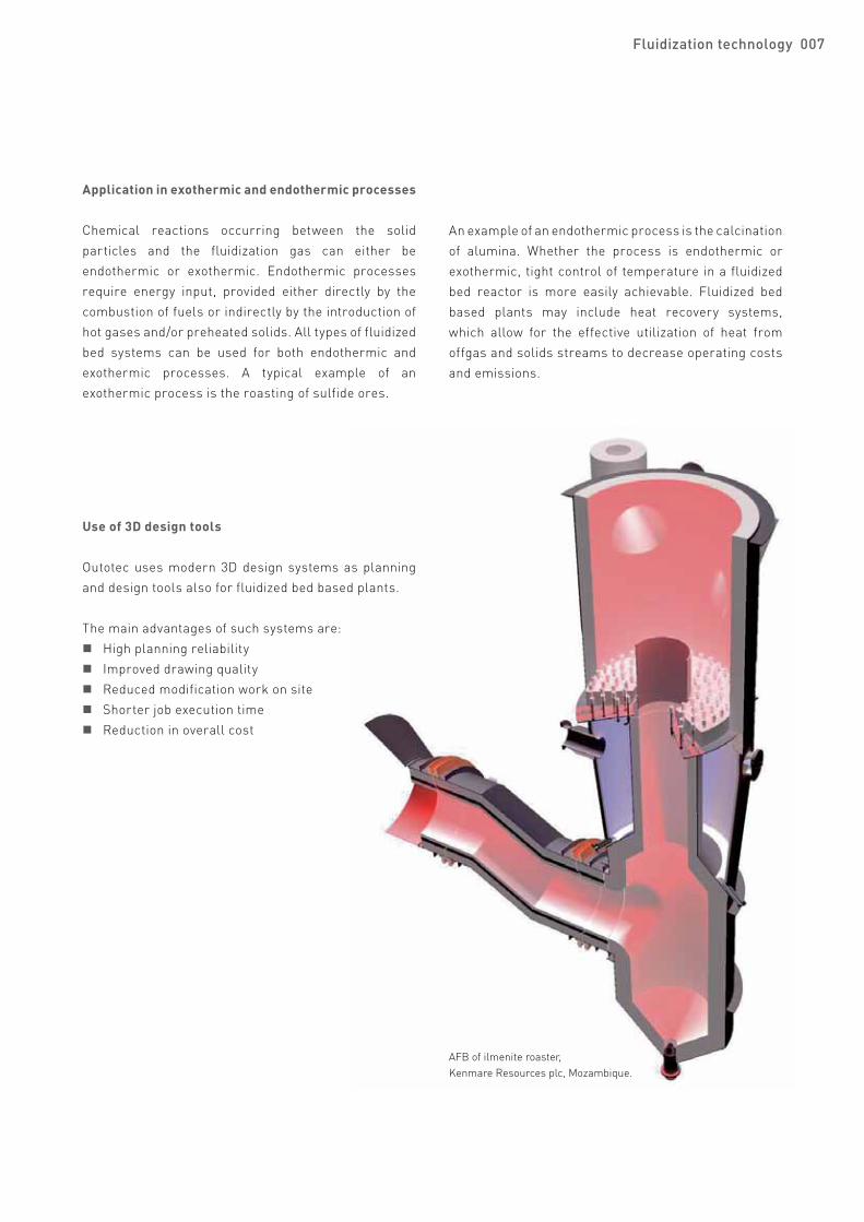
AFB of ilmenite roaster, Kenmare Resources plc, Mozambique.
Application in exothermic and endothermic processes
Chemical reactions occurring between the solid particles and the fluidization gas can either be endothermic or exothermic. Endothermic processes require energy input, provided either directly by the combustion of fuels or indirectly by the introduction of hot gases and/or preheated solids. All types of fluidized bed systems can be used for both endothermic and exothermic processes. A typical example of an exothermic process is the roasting of sulfide ores.
An example of an endothermic process is the calcination of alumina. Whether the process is endothermic or exothermic, tight control of temperature in a fluidized bed reactor is more easily achievable. Fluidized bed based plants may include heat recovery systems, which allow for the effective utilization of heat from offgas and solids streams to decrease operating costs and emissions.
Use of 3D design tools
Outotec uses modern 3D design systems as planning and design tools also for fluidized bed based plants.
The main advantages of such systems are: n High planning reliability n Improved drawing quality n Reduced modification work on site n Shorter job execution time n Reduction in overall cost
Outotec's pursuit of new fluidized bed applications for customer needs is supported by experimental work in the
company's in-house R&D Center. For example development of neural networks, in-situ monitoring systems and
modern mathematical methods, including computational fluid dynamics modeling, are key elements of research.
Scale up experienceWith Outotec's experience in many state-of-the-art fluidized bed technologies the customers do not need a large scale demonstration plant as an expensive interim step. Examples of the scale up figures:
Process, year From pilot plant size To industrial plant size Scale up factorAlumina calcination, 1970 D=1,000 mm/24 tpd D=3,600 mm/500 tpd 1:20Coal combustion, 1982 D=360 mm/20 kg/h D=5,000 mm/500 tpd 1:1,000Gold ore roasting, 1990 D=200 mm/22 kg/h D=3,800 mm/2,000 tpd 1:4,000Circored, 1999 D=200 mm/8 kg/h D=5,000 mm/1,500 tpd 1:3,500
R&D and scale up competence
Outotec has developed theoretical models of fluidized bed systems and specialist scale up know-how over many decades. A unique set of pilot plants, suitable for processing of feeds in the range of 100 g batches up to 1,000 kg/h continuously, is available to develop and improve existing technologies for customer applications. These pilot plants are designed to be flexible with respect to temperature, pressure, gas and fluidization conditions and can be configured either as single or multistage units. However, the data gained in laboratory scale fluidized bed systems are not sufficient to provide design and performance criteria of industrial plants without the experience of operating facilities.
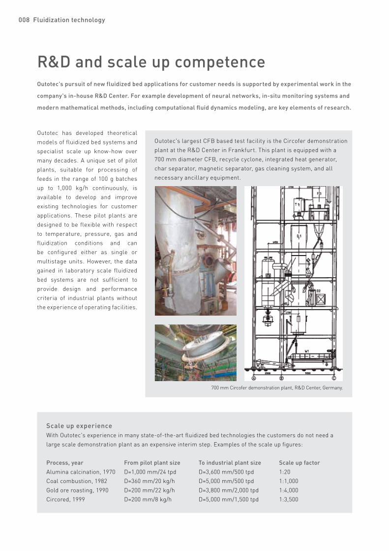
700 mm Circofer demonstration plant, R&D Center, Germany.
Outotec's largest CFB based test facility is the Circofer demonstration plant at the R&D Center in Frankfurt. This plant is equipped with a 700 mm diameter CFB, recycle cyclone, integrated heat generator, char separator, magnetic separator, gas cleaning system, and all necessary ancillary equipment.
008 Fluidization technology

Applications Outotec's portfolio related to fluidized bed technology can be classified as follows.
Reducing conditions
n Dearsenifying pyrite roasting n Circored (gas based fine ore reduction) n Circofer (coal based fine ore reduction) n Circodust (processing of steel plant residues) n Circosmelt (prereduction and
smelting of ilmenite) n Reducing ilmenite roasting n Heat recovery by fluidized bed cooling and
Circotherm n Circoheat (preheating of ore fines) n Circochar (coal charring) n Circonickel (prereduction of lateritic nickel ore) n Partial roasting of copper concentrate
Oxidizing conditions
n Alumina calcining n Roasting of pyrite, copper and zinc concentrates n Roasting of gold ore n Oxidizing ilmenite roasting n Heat recovery by fluidized bed cooling and
Circotherm n Circoheat (preheating of ore fines) n Circoroast (improved pyrite roasting system)
Diagram for fluidized bed applications.
Fluidization technology 009
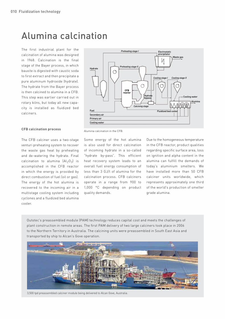
Alumina calcinationThe first industrial plant for the calcination of alumina was designed in 1968. Calcination is the final stage of the Bayer process, in which bauxite is digested with caustic soda to first extract and then precipitate a pure aluminum hydroxide (hydrate). The hydrate from the Bayer process is then calcined to alumina in a CFB. This step was earlier carried out in rotary kilns, but today all new capa-city is installed as fluidized bed calciners.
CFB calcination process
The CFB calciner uses a two-stage venturi preheating system to recover the waste gas heat by preheating and de-watering the hydrate. Final calcination to alumina (Al2O3) is accomplished in the CFB reactor in which the energy is provided by direct combustion of fuel (oil or gas).The energy of the hot alumina is recovered to the incoming air in a multistage cooling system including cyclones and a fluidized bed alumina cooler.
Some energy of the hot alumina is also used for direct calcination of incoming hydrate in a so-called ”hydrate by-pass”. This efficient heat recovery system leads to an overall fuel energy consumption of less than 3 GJ/t of alumina for the calcination process. CFB calciners operate in a range from 900 to 1,000 °C depending on product quality demands.
Due to the homogeneous temperature in the CFB reactor, product qualitiesregarding specific surface area, losson ignition and alpha content in the alumina can fulfill the demands of today’s aluminium smelters. We have installed more than 50 CFB calciner units worldwide, which represents approximately one third of the world's production of smelter grade alumina.
Alumina calcination in the CFB.
Outotec's preassembled module (PAM) technology reduces capital cost and meets the challenges of plant construction in remote areas. The first PAM delivery of two large calciners took place in 2006 to the Northern Territory in Australia. The calcining units were preassembled in South East Asia and transported by ship to Alcan's Gove operation.
3,500 tpd preassembled calciner module being delivered to Alcan Gove, Australia.
Hydrate
Fuel
Secondary airPrimary air
Cooling water
Preheating stage I
Preheating stage II
CFBreactor
Calcining stage
Cooling stage I Cooling stage II
Cooling water
Alumina
Fluidized bed cooler
Hydratebypass
Electrostatic precipitator
Waste gas
010 Fluidization technology
006 More out of ore!
Roasting of sulfide ores
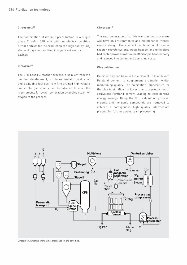
Gold ore roasting in the CFB.
Pyrite roasting in the FB
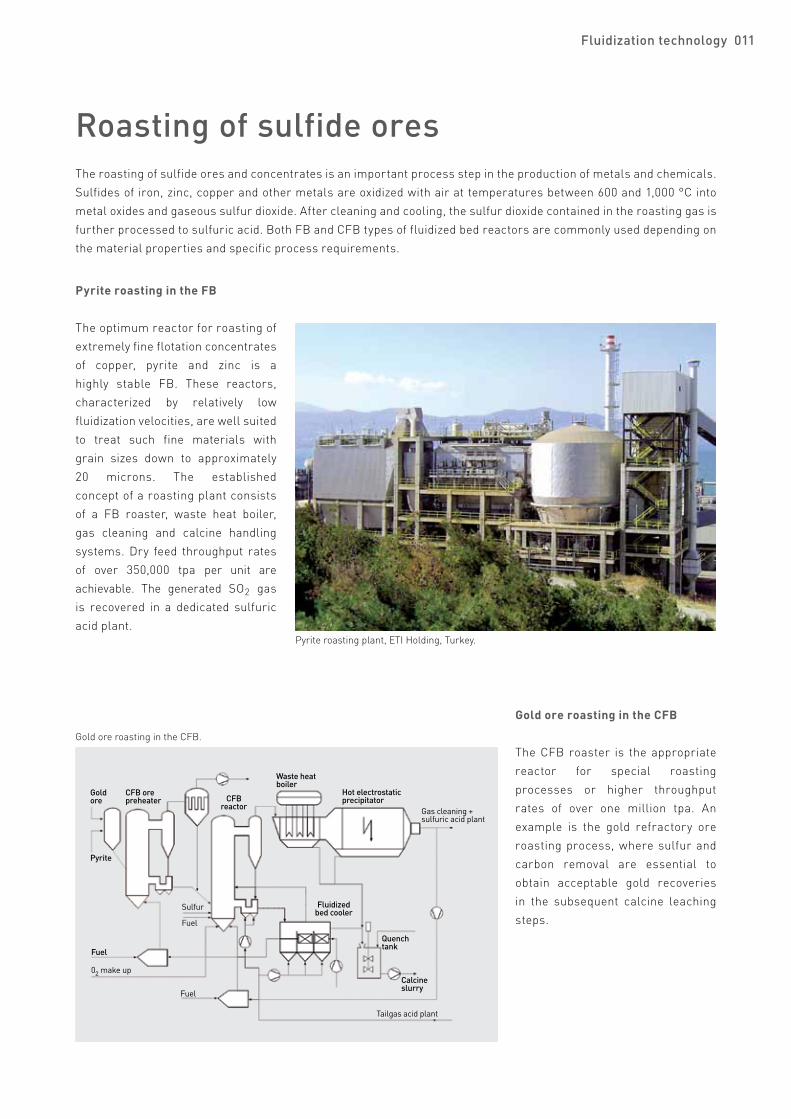
The optimum reactor for roasting of extremely fine flotation concentrates of copper, pyrite and zinc is a highly stable FB. These reactors, characterized by relatively low fluidization velocities, are well suited to treat such fine materials with grain sizes down to approximately 20 microns. The established concept of a roasting plant consists of a FB roaster, waste heat boiler, gas cleaning and calcine handling systems. Dry feed throughput rates of over 350,000 tpa per unit are achievable. The generated SO2 gas is recovered in a dedicated sulfuric acid plant.
Pyrite roasting plant, ETI Holding, Turkey.
Gold ore roasting in the CFB
The CFB roaster is the appropriate reactor for special roasting processes or higher throughput rates of over one million tpa. An example is the gold refractory ore roasting process, where sulfur and carbon removal are essential to obtain acceptable gold recoveries in the subsequent calcine leaching steps.
The roasting of sulfide ores and concentrates is an important process step in the production of metals and chemicals. Sulfides of iron, zinc, copper and other metals are oxidized with air at temperatures between 600 and 1,000 °C into metal oxides and gaseous sulfur dioxide. After cleaning and cooling, the sulfur dioxide contained in the roasting gas is further processed to sulfuric acid. Both FB and CFB types of fluidized bed reactors are commonly used depending on the material properties and specific process requirements.
Gold ore
Pyrite
CFB orepreheater
Fuel
02 make up
Fuel
Fuel
Sulfur
CFBreactor
Waste heat boiler
Hot electrostaticprecipitator
Gas cleaning + sulfuric acid plant
Fluidized bed cooler
Quenchtank
Calcine slurry
Tailgas acid plant
Fluidization technology 011

Iron ore preheating and direct reduction Circored®
The drivers for the development of the Circored process in the early 1990s were the growing demand for direct reduced iron (DRI) coupled with the advantages of using iron ore fines directly in the steelmaking value chain, avoiding the agglomeration step. The Circored process, using hydrogen as the only reductant, applies a two-stage CFB/FB reactor configuration for reduction. In addition, a single CFB is utilized for ore preheating and an AFB based flash heater is used to achieve the DRI briquetting temperature. The first commercial Circored plant, with an annual capacity of 500,000 t of hot briquetted iron (HBI), commenced operations in 1999 in Trinidad.
Circored direct reduction in the CFB/FB.
Circoheat™
The first commercial Circoheat plant, operating at HIsmelt's Kwinana facility in Western Australia is capable of preheating approximately 1,300,000 tpa of iron ore fines to 850 °C using offgas from the HIsmelt smelt reduction vessel (SRV). In the Circoheat process, wet iron ore fines are fed to a suspension preheater system where they are preheated to approximately 500 °C prior to introduction into a CFB reactor. Hot combustible SRV offgas at a temperature of 1,000 °C is introduced into the CFB reactor via an AFB system. The offgas is partially combusted with air to generate the necessary energy for preheating the iron ore. Since the SRV gas is not completely combusted, a reduction of the iron ore to the magnetite/wuestite stage is achieved. The preheated material is subsequently pressurized in a lock hopper system and injected at high temperature into the SRV via a new pneumatic hot ore conveying system.
Ore preheater, HIsmelt Corporation, Australia.
Offgasscrubber
To thickener
SuspensionpreheaterIron
ore
CFBpreheater
Air
Preheating system
Feedsystem
Bucket elevator
Recyclecyclone
ReductionsystemCFB
stageI
FB stage II
Naturalgas
Fuel Air
Process gas heater
Fuel Air
Hydrogenmake up
Flashheater
DRI discharge
CycloneProduct handlingsystem
Hotbriquettingoption
HBI
Hotchargingoption
EAFSteel
Bleedas fuel
To thickener
Process gasscrubber
Multi-clone
Process gascompressor
Process gasheat exchanger
Fuel
012 Fluidization technology
Steam reforming

Latest developments
Circored plant, CAL, Trinidad.
Circofer CFB prereduction step for HIsmelt.
Based on the wealth of experience gained in the field of fluidization technology, Outotec is continuously working
on improving existing processes and developing new processes and applications to meet the demands of an
industry pursuing sustainable solutions.
Coal
Dol
omite
Char
Stand pipe
Oredryer
Hot airCoal crushing
Pneumaticcoal feeding
Multiclone Process gas scrubber
Stage I
Preheating
Stage II Reduction
CFBreactor
Heatgene-rator
Process gasheater
Air
Bleed gas
Process gascompressor
Charseparator
Hotinjection
Recyclechar
Prereducediron and char
HlsmeltSRV
Hotmetal
with 4% C
Slag
CoalOffgas
SteamHot air
Smelting
ThickenerCO2
CO2absorber
Fluidization technology 013
One possible application of Circofer is as a single stage prereduction step for the HIsmelt® process, replacing the Circoheat ore preheater. This leads to a significant increase in the throughput of the HIsmelt SRV.
Iron
ore
O2
Circofer®
The Circofer process has been developed to reduce iron ore fines utilizing coal as reductant. Similar to the Circored process, Circofer uses a two-stage CFB/FB reactor configuration to obtain a highly metallized product. A heat generator is integrated into the CFB prereduction circuit to provide the energy necessary for the endothermic reduction reaction by partially combusting the introduced coal with oxygen. The process operates at reduction temperatures of approximately 950 °C in a closed gas circuit without the production of export gas.
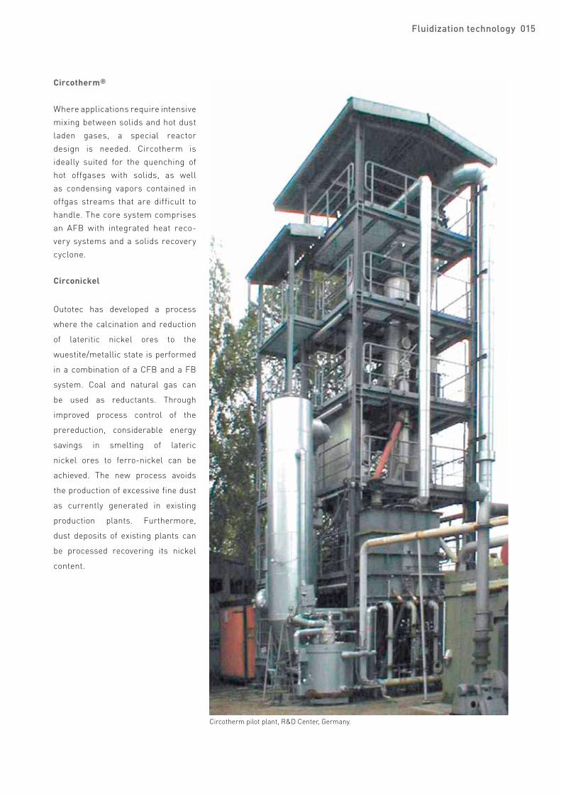
Circosmelt®
The combination of ilmenite prereduction in a single stage Circofer CFB unit with an electric smelting furnace allows for the production of a high quality TiO2 slag and pig iron, resulting in significant energy savings.
Circochar®
The CFB based Circochar process, a spin-off from the circofer development, produces metallurgical char and a valuable fuel gas from fine grained high volatile coals. The gas quality can be adjusted to meet the requirements for power generation by adding steam or oxygen to the process.
014 Fluidization technology
Goal
Char
Ilmen
ite
Pneumatictransport
Heatgene-rator
CFB
Stage I
Preheating
Stage II
Multiclone Venturi scrubber
Hotmagneticseparation
Process gascompressor
Processgas heater
O2
Dust
Gaslift
Recylechar
PrereducedIlmenite
CO2absorber
Steam
Offgas
Titania slag
AirPig iron
Smeltingfurnace
CO2Thickener
Circosmelt: Ilmenite preheating, prereduction and smelting.
Circoroast®
The next generation of sulfide ore roasting processes will have an environmental and maintenance friendly reactor design. The compact combination of roaster reactor, recycle cyclone, waste heat boiler and fluidized bed cooler provides maximum efficiency in heat recovery and reduced investment and operating costs.
Clay calcination
Calcined clay can be mixed in a ratio of up to 40% with Portland cement to supplement production whilst maintaining quality. The calcination temperature for the clay is significantly lower than the production of equivalent Portland cement leading to considerable energy savings. Using the CFB calcination process, organic and inorganic compounds are removed to achieve a homogenous high quality intermediate product for further downstream processing.
Fluidization technology 015
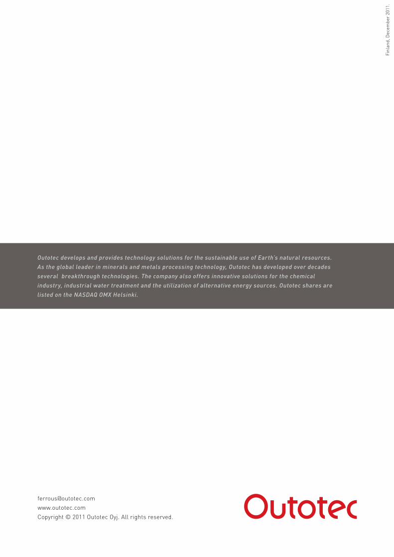
Circotherm®
Where applications require intensive mixing between solids and hot dust laden gases, a special reactor design is needed. Circotherm is ideally suited for the quenching of hot offgases with solids, as well as condensing vapors contained in offgas streams that are difficult to handle. The core system comprises an AFB with integrated heat reco-very systems and a solids recovery cyclone.
Circonickel
Outotec has developed a process
where the calcination and reduction
of lateritic nickel ores to the
wuestite/metallic state is performed
in a combination of a CFB and a FB
system. Coal and natural gas can
be used as reductants. Through
improved process control of the
prereduction, considerable energy
savings in smelting of lateric
nickel ores to ferro-nickel can be
achieved. The new process avoids
the production of excessive fine dust
as currently generated in existing
production plants. Furthermore,
dust deposits of existing plants can
be processed recovering its nickel
content.
Circotherm pilot plant, R&D Center, Germany.
[email protected] © 2011 Outotec Oyj. All rights reserved.
Finl
and,
Dec
embe
r 20
11.
Outotec develops and provides technology solutions for the sustainable use of Earth’s natural resources.
As the global leader in minerals and metals processing technology, Outotec has developed over decades
several breakthrough technologies. The company also offers innovative solutions for the chemical
industry, industrial water treatment and the utilization of alternative energy sources. Outotec shares are
listed on the NASDAQ OMX Helsinki.