organized accessible systems - pathnet
TRANSCRIPT
Concept Home Principles -
Organized & Accessible Systems
Research Summary
June 2005

Acknowledgements Preparation of this report was coordinated by Dr. Carlos Martín of the U.S. Department of Housing and Urban Development’s Office of Policy Development and Research. The text was developed by Tate Era and James Lyons P.E. and reviewed by Mark Nowak of Newport Partners, LLC. The assistance and support of Tedd Benson of Bensonwood Homes and Fernando Pagés Ruiz is also acknowledged and greatly appreciated.
Disclaimer The statements and conclusions contained in this report are those of Newport Partners LLC and do not necessarily reflect the views or policies of the U.S. Department of Housing and Urban Development or the U.S. Government. The authors have made every effort to verify the accuracy and appropriateness of the report’s content. However, no guarantee of the accuracy or completeness of the information or acceptability for compliance with any industry standard or mandatory requirement of any code, law, or regulation is either offered or implied. The products and systems described in the report are included only as examples of some available choices. No endorsement, recommendation, or evaluation of these products or their use is given or implied.

Background ........................................................................................................................ 1
Performance Objectives ..................................................................................................... 3
Supporting Technologies & Design Approaches.............................................................. 4 HVAC......................................................................................................................................... 4
High Velocity HVAC Systems ............................................................................................................. 4 Underfloor Air Distribution Systems .................................................................................................... 5 Duct-less HVAC Systems..................................................................................................................... 5 Minimized and Accessible Duct Systems ............................................................................................. 6 Combustion Appliance Venting Strategies ........................................................................................... 8 Wireless Thermostat Systems ............................................................................................................... 9 Central Fan-Integrated Mechanical Ventilation Systems...................................................................... 9
Plumbing.................................................................................................................................. 10 Stacked/Adjacent Plumbing Designs .................................................................................................. 10 Flexible Water Piping ......................................................................................................................... 11 Plumbing Manifolds............................................................................................................................ 12 Modular Plumbing Connections ......................................................................................................... 13 Flexible Natural Gas Supply Lines ..................................................................................................... 14 Air Admittance Vents (AAVs) ........................................................................................................... 14
Electrical/Communications .................................................................................................... 15 Prefabricated Wiring Chases in Wall Panels....................................................................................... 16 Electrical Raceways ............................................................................................................................ 17 Busways.............................................................................................................................................. 18 Flat Wiring.......................................................................................................................................... 18 Wireless Doorbell and Alarm Systems ............................................................................................... 19
Lighting.................................................................................................................................... 19 Wireless Lighting Controls ................................................................................................................. 19 Remote Source Lighting ..................................................................................................................... 20 Solid-state Lighting............................................................................................................................. 21
Structure .................................................................................................................................. 22 Clear-Span Structural Designs ............................................................................................................ 22
Organizing Mechanisms ......................................................................................................... 26 Central Utility Cores ........................................................................................................................... 26 Matura Infill System ........................................................................................................................... 27 ERA Infill System............................................................................................................................... 28 Interlevel ............................................................................................................................................. 28 Owens Corning Basement Finish System ........................................................................................... 28 Other Infill System Examples ............................................................................................................. 29
Conclusion........................................................................................................................ 31
Reference List................................................................................................................... 32
Concept Home Principles –Organized and Accessible Systems
Research Summary
Background The advance of technology has touched every part of our lives over the last century—including our houses. In the past, houses were connected to very few external networks or systems, and in many cases a road was the sole “connection” between a house and a larger infrastructure network. Connections to a centralized electric grid or a natural gas distribution system simply did not exist, and many houses were simply comprised of the structure itself, a central fireplace, and a floor plan with spaces that adapted to different uses. Conversely, a home built today is connected to a multitude of services that greatly enhance the performance and comfort of a house—services such as water supply, sewer, electric power, natural gas, communications, and security. However, the manner in which these services are distributed throughout a house involves intertwining these systems with each other and with other distinct home components—notably the structure of the house and the floor plan. This entangling of the house structure (e.g., exterior walls, floor and roof systems), its mechanical systems (e.g., HVAC, plumbing, electrical), and the floor plan (e.g. interior walls and finishes) has developed inadvertently as a way to accommodate the ever-growing set of mechanical systems, but it carries significant penalties as well. Entanglement of the structure, mechanical systems, and floor plan in modern housing creates space conflicts and production inefficiencies during construction, undermines the quality of individual building systems, and complicates long-term maintenance and remodeling efforts. These three “layers” of a home each have distinct requirements for installation, operation, and long-term serviceability that are compromised when they are physically coupled with each other in a random and disorganized manner. The pathway from houses with virtually no mechanical systems to the current state of entanglement was certainly not planned, but has simply been shaped by technological developments. As various mechanical systems within the home developed over time—starting with indoor plumbing in the mid- to late-1800’s and continuing with the addition of central hot water, electricity supply, and telephone service—the design of new systems focused solely on adding them to the home with little regard for other systems or the structure. Technology development and integration in houses was a near-sighted process in which each successive system was simply added wherever space allowed. The wood framing used in many site-built houses offered space in walls and floor systems for adding new components, which led to an approach of simply installing new systems where they would fit.
“Most new homes are largely entangled systems. Their design does not acknowledge that each system has a different useful lifespan. Systems with longer lifetimes often encapsulate short lifetime components, which makes the latter’s replacement difficult. The challenge in a new model for housing production is to achieve function integration of components, while maintaining physical independence and ensuring design flexibility and ease of access, repair, and replacement.” - Organizing Residential Utilities: A New Approach to Housing Quality, HUD 2004
Concept Home Principles – 1 Organized and Accessible Systems
As additional utilities were added like central air-conditioning in the 1950’s, entanglements between the mechanical systems themselves and between these systems, the structure, and the floor plan became more evident. Given its relatively large size and rigid material, the arrival of central air-conditioning has driven some measure of utility pre-planning and cross-trade coordination, but to a limited extent. In fact, HVAC installations (which typically occur first among mechanical rough-ins) are sometimes damaged or modified after the fact as other trade contractors attempt to install their system. Recently, the rapid advancement of electronics and related technologies has increased the amount of wiring and access points necessary within the walls of the home. Structured wiring helps to combine and organize audio, video, and a host of other electronic components into a single distribution network. Although structured wiring systems offer increased electronic compatibility in an organized fashion, it also greatly increases the number of wires placed within the structure, which can hinder disentanglement. Given mechanical systems’ distinct functions, different components, and different development histories, these systems have been viewed as completely separate entities. Systems have not been considered in terms of their potential technical interactions with each other, or even in terms of their respective physical layouts within the home. Still today, three or more different crews typically complete the design and installation of the three major mechanical systems with little pre-planning or coordination. The origin points and end points of systems are often specified on plans, but installers determine the pathways in between these points on-site as they perform their individual tasks. The principle of organized and accessible systems is to reduce entanglements among the structure, mechanical systems, and floor plan to promote more efficient home construction and enable easier maintenance and changes to a house over time. This Concept Home principle encompasses technologies and design techniques that promote organized mechanical systems, and a rational and planned interaction between the structure, mechanical systems, and floor plan of a home. Instead of haphazardly placing systems in a structure as it is built, space requirements, physical interdependencies, and long-term access to systems is carefully considered. This approach leads to mechanical systems that are installed more efficiently and with a higher degree of quality. These systems are also accessible and organized, easing future repairs and upgrades. Similarly, the structure and interior walls of a home are also arranged in a manner that promotes design flexibility and long-term serviceability, while still providing the basic functions expected from each system. While this concept may present a challenge to designers, builders, and manufacturers, consumers want the ability to effectively access, repair, and modify their houses over time. Market research on this Concept Home principle has demonstrated that homeowners value the concept of easily accessed mechanical systems that can be readily repaired and upgraded, and they want this flexibility in an attractive design at a reasonable cost. Designing for system repairs and updates during the initial construction of a house offers significant benefits, as homeowners spent $15.4 billion—or 11% of all home improvement spending—on the replacement or upgrading of systems and equipment in 2003 (Joint Center for Housing Studies 2005). Consumers benefit further from systems that are well installed and function effectively. Builders and contractors benefit from more rationalized utility systems in the form of faster, more straightforward system installations. And
Concept Home Principles – 2 Organized and Accessible Systems
innovative manufacturers also benefit from this approach, as it provides an opportunity to develop and market products that support organized and accessible systems. In fact, this report discusses many such emerging products—several of which have won awards for their innovation.
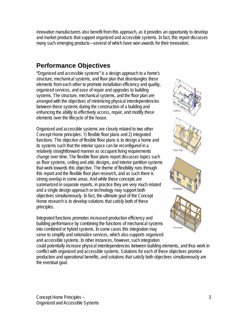
Performance Objectives “Organized and accessible systems” is a design approach to a home’s structure, mechanical systems, and floor plan that disentangles these elements from each other to promote installation efficiency and quality, organized services, and ease of repair and upgrades to building systems. The structure, mechanical systems, and the floor plan are arranged with the objectives of minimizing physical interdependencies between these systems during the construction of a building and enhancing the ability to effectively access, repair, and modify these elements over the lifecycle of the house. Organized and accessible systems are closely related to two other Concept Home principles: 1) flexible floor plans and 2) integrated functions. The objective of flexible floor plans is to design a home and its systems such that the interior space can be reconfigured in a relatively straightforward manner as occupant living requirements change over time. The flexible floor plans report discusses topics such as floor systems, ceiling and attic designs, and interior partition systems that work towards this objective. The theme of flexibility runs through this report and the flexible floor plan research, and as such there is strong overlap in some areas. And while these concepts are summarized in separate reports, in practice they are very much related and a single design approach or technology may support both objectives simultaneously. In fact, the ultimate goal of the Concept Home research is to develop solutions that satisfy both of these principles. Integrated functions promotes increased production efficiency and building performance by combining the functions of mechanical systems into combined or hybrid systems. In some cases this integration may serve to simplify and rationalize services, which also supports organized and accessible systems. In other instances, however, such integration could potentially increase physical interdependencies between building elements, and thus work in conflict with organized and accessible systems. Solutions for each of these objectives promise production and operational benefits, and solutions that satisfy both objectives simultaneously are the eventual goal.
Concept Home Principles – 3 Organized and Accessible Systems

Supporting Technologies & Design Approaches The sections below offer examples of methods and technologies that support Organized and accessible systems in single-family houses. The technologies reviewed below represent a cross-section of approaches for making mechanical systems more organized and minimizing entanglements between the structure, mechanical systems, and the floor plan. These reviews are not all inclusive and the goal is not to include all of these items in all homes. Rather, the highlighted options illustrate design- and technology-based approaches, and the actual selection and use of the various technologies will depend on the design of a particular home. It should also be noted that while this research focuses on design and technology approaches to disentanglement, other potential solutions are also rooted in much broader alternatives to the process through which homes are currently designed and constructed. Design and technology options that promote organized and accessible systems are organized below by building systems, with separate categories for HVAC, Plumbing, Electrical/ Communications, Lighting, and Organizing Mechanisms. Additional options for these same building systems may also be found in the research reports for the two related Concept Home principles as mentioned above.
HVAC HVAC systems within a home provide the heating, cooling, and ventilation for the living space. The major components of HVAC systems are a heating/cooling source (e.g., furnace, split A/C system, boiler), a distribution system (e.g., ducts, pipes), and outlets in the living space for providing heating and cooling (e.g., air registers, radiators). Additional components include system controls, ventilation fans and ducts (e.g., bathroom exhaust), and building shell components like hoods for exhaust ducts. HVAC systems often require supply lines from other mechanical systems too, including electrical, plumbing, and natural gas lines. Taken together, this collection of components can form an extensive network throughout a house that is challenging to disentangle from other systems and the structure. While a number of design techniques can be employed to reduce the degree of entanglement of HVAC systems, one general practice that applies to any design is proper system sizing. Proper load and duct sizing based on widely accepted design tools, such as Manuals J and D from the Air-Conditioning Contractors of America (ACCA), is critical for providing an accurately sized system. A sizing analysis will often result in smaller (and less expensive) HVAC units and duct sizes compared to rule-of-thumb methods. Smaller duct sizes reduce material cost, and can also allow lines to be run through limited openings such as the gaps in open-web floor trusses, where larger ducts would not fit. A proper sizing analysis can also accurately capture the benefits of innovative insulation and air sealing technologies. Beyond proper sizing, a range of other technologies and design opportunities that can help to rationalize and disentangle HVAC systems are highlighted below.
High Velocity HVAC Systems High velocity systems use smaller diameter ducts (~2”), higher airflow velocities (up to 2,000 fpm), and specially designed components to provide an alternative to conventional forced-air systems.
Concept Home Principles – 4 Organized and Accessible Systems

High velocity systems are often used in retrofit applications, where the reduced space requirements for these systems make them an attractive option. This is especially true for retrofits in homes without forced-air systems that need to have central air-conditioning added. Given that forced-air systems are usually the most bulky mechanical system in new home construction, some entanglement issues may be addressed through the use of a smaller alternative. High velocity, or “mini-duct” systems as they are sometimes called, can be fit into floor and ceiling cavities relatively easily compared to larger ducts used in traditional systems. Further, the supply grilles used in these systems are smaller in size (~ 5” OD) and designed to have a subtle appearance. Manufacturers of high velocity systems claim that installations in new home construction are increasing, due in part to the systems’ small size and design flexibility. A common application for these systems is to serve as the primary cooling system and a supplemental heating system that supports a primary heating system such as radiant floor heating. Manufacturers like Unico (www.unicosystem.com/Index.html) also apply high velocity systems to factory-built homes, including both manufactured and modular homes. The systems can be installed in the homes within the factory setting to a large extent—up to 90% according to Unico. The mini-duct runs are installed along with all outlets to the living space. Once the factory-built units are set on site, duct connections are made at the unit mating walls. The air handler and heating and/or cooling modules are also installed on-site. Factors to consider when using a high velocity duct system include: • Initial cost • Outlet locations (recommended location is a ceiling within 5” of a wall) • Ability to serve as the primary heating system
Underfloor Air Distribution Systems Underfloor air distribution systems can use the floor cavity area as a forced-air plenum. This affords a great deal of flexibility in locating and re-locating supply registers, and has recently gained popularity in commercial building designs. Commercial buildings like offices must accommodate a great deal of floor plan change, and underfloor air distribution systems are seen as a viable option for providing flexibility in HVAC design. This design approach is discussed in greater detail in the “Flexible Floor Plans” report.
Duct-less HVAC Systems HVAC systems without ducts are a general category of HVAC systems that do not rely on sheet metal, flex, or fiberglass ductwork to deliver conditioned air to the living space. A system without ducts can help organize and simplify the installation of mechanical systems, since ductwork is a bulky component that is often challenging to locate, especially in retrofits. In areas that typically use heating and cooling systems (e.g. most of the U.S.), a ductless system(s) must account for both functions. HVAC system options that do not rely on ductwork, along with basic system characteristics, are listed below.
Concept Home Principles – 5 Organized and Accessible Systems

• Radiant floor heating systems provide heating only, and typically require a network of piping
under the floor surface to supply heat. Radiant floor heating systems may be applied in small- to large-sized areas, and can be divided into different zones with independent controls relatively easily.
• Electric baseboard systems utilize baseboard units heated by electric resistance to provide heat directly into living spaces. They are connected to the house’s electrical system, and can be controlled individually or grouped into banks of heaters controlled by a single thermostat.
• Radiant panel systems are heating systems in the form of wall- or ceiling-mounted panels that radiate heat into the living area. They are typically electrically heated and can be controlled by thermostats.
• Mini-split systems are a duct-less variation of central heat pump or AC system in which a central outdoor unit (compressor) serves multiple, smaller indoor units. The indoor units are equipped with an evaporator coil, refrigerant lines run from the outdoor compressor, and fans to deliver heated/cooled air directly into the living area. Indoor units are typically flush-mounted on a wall or ceiling in a room, and can be controlled as a separate zone with a dedicated thermostat.
• Window AC units contain all of the equipment for refrigerant compression cooling within the unit, and directly cool the living areas from their window-mounted locations. Units are controlled individually, and rely only upon a plug connection for electrical power.
• Through-the-wall AC and heat pump units are cooling and heating/cooling systems, respectively, which are installed in a wall opening in the building envelope. Air source heat pumps may also include electric resistant heating cooling. Through-the-wall units are typically operated individually by controls on the unit.
A minimized duct layout at a PATH field evaluation site. The duct system utilizes short supply takeoffs
and is located within conditioned space. Image Source: ToolBase Website
(www.toolbase.org)
In addition to first cost implications, a major challenge with many of these systems is homebuyer reaction to locating HVAC equipment within individual rooms. The noise and appearance of such installations may not be desirable compared to a traditional central forced-air system. On the other hand, the potential advantages of these systems include increased accessibility, greater control of room and zonal temperatures, and an improved ability to reconfigure and expand indoor spaces.
Minimized and Accessible Duct Systems Minimized run duct systems utilize designs that rely on traditional ductwork, but to a more limited extent. While traditional duct layouts locate supply registers near the perimeter of a floor plan to “wash the windows” with
Concept Home Principles – 6 Organized and Accessible Systems

conditioned air, minimized duct designs locate supplies more towards the interior of a building. This approach reduces the length of supply runs and the quantity of duct work in a building, which can help to reduce utility entanglements that result from bulky duct runs. This approach also reduces material costs since shorter duct runs are required. Traditional duct layouts have located supply registers near windows on exterior walls to help offset condensation and cold drafts from glazing. However, improved thermal performance from modern windows and more attention to indoor humidity control can eliminate the need to direct conditioned air near windows. Thus, duct layouts can be more centralized with supply runoffs designed to be much shorter and possibly taken directly off the main supply trunk (as shown in the picture). Providing access to minimized duct systems—while keeping the duct systems within the thermal envelope of the house to improve energy efficiency—can be accomplished through a variety of methods, including: • Cathedralized attic designs • Plenum truss designs • Sealed crawlspace designs • Dropped and accessible ceilings Cathedralized Attic Designs Seemingly straightforward ways to make ducts accessible and decoupled from the structure and the floor plan, such as running duct work through attics instead of walls and floors, can also impose significant energy efficiency penalties. Designing attics to be within the thermal envelope of the house (e.g., insulating at the roof line) is one approach to gaining extra space for storage or expandable space, and can also provide an area in which ducts can be easily routed and accessed. Designs of this nature, often called cathedralized attics or non-vented attics, must incorporate roof framing that provides for an open space in the attic, and also account for insulating details and roof ventilation issues. This design approach is discussed further in the Concept Home report “Flexible Floor Plans.” Plenum Trusses A variation of the cathedralized attic approach is the use of plenum trusses to create a cavity within the attic that is still within the thermal envelope of the house. A modified scissors truss can be used to create this cavity between the top of the ceiling plane and the bottom chord of the truss, as shown in the image below. A material like OSB or gypsum is fastened to the bottom chord of the truss and then air sealed to isolate this cavity from above, and then insulation is applied on top of this surface. This approach essentially creates a dedicated soffit for HVAC distribution above the living space but within the thermal envelope and air barrier envelope of the house. This cavity can also be made accessible by designing it with access panels either from above or below. In terms of organized and accessible systems, using plenum trusses for HVAC distribution can help to disentangle ducts from the structure and the floor plan by creating a dedicated and accessible space for this system.
Concept Home Principles – 7 Organized and Accessible Systems

Sealed Crawlspace Systems Crawlspace duct installations are similar to systems located in attics: there is ample space for horizontal duct runs but the design carries efficiency penalties because it locates ducts in unconditioned space. A sealed crawlspace, however, offers the opportunity to rout ducts in a manner that decouples the system from the structure and floor plan, provides ongoing access to the systems, and maintains efficiency by locating ducts within an insulated space. Sealed, or non-ventilated, crawlspace designs should incorporate several design features to ensure an insulated area which handles moisture appropriately (HUD 2002). Minimum details include: • Insulating at the perimeter walls • Ground vapor barrier cover (6 mil) with lapped joints • Damp-proofed foundation wall • Minimum 4 percent exterior grading • Careful air sealing between outdoors and the crawlspace area Crawlspace foundations that incorporate this design approach provide an insulated area where HVAC (and other mechanicals) can be located and accessed with minimal interdependencies on the structure or floor plan. Dropped and Accessible Ceilings Dropped ceiling systems are another method to routing HVAC ducts in a relatively open area that can also be made accessible. Dropped ceiling systems may be formed from common building materials in areas like hallways and equipped with access panels or hatches. Providing access in this manner helps to simplify future repairs or system upgrades. Specialized systems from manufacturers like Armstrong (www.armstrong.com) are also available, and often incorporate easily removed panels. Armstrong also offers quick installation systems like its Shortspan™ Drywall Grid System, which utilizes clips and a track system to form a dropped frame that does not require vertical support for spans less than 6 feet.
Combustion Appliance Venting Strategies Venting systems for HVAC equipment like high efficiency condensing furnaces can be done directly through the wall of a house, instead of running a flue stack upward in a chase and terminating it above the roof. Condensing furnaces typically use PVC plastic pipes to exhaust combustion gases to outdoors, and because this exhaust is cooler than for traditional furnaces it can be exhausted to outdoors through a sidewall vent. This flexibility can eliminate the need for a vertical chase and flue ducting upward through the house. Other examples of products that reduce or minimize venting systems for combustion appliances include direct vent fireplaces and vent-free fireplace products.
Concept Home Principles – 8 Organized and Accessible Systems

Wireless Thermostat Systems Wireless HVAC control technologies can help create an organized/accessible HVAC system by providing temperature sensing and control in a house without a hard-wired thermostat. Wireless systems typically consist of the thermostat (sensor) itself and a receiver located at the heating/cooling unit. The setup simplifies the initial construction phase by eliminating one wiring run and one drywall penetration for the thermostat. The wireless setup also allows the thermostat to be moved more readily during future renovations or to accommodate shifts in how living space in a home is used.
Further, in homes with seasonal stratification issues, moving the thermostat may help keep a house more comfortable for occupants. One issue to consider when utilizing a wireless thermostat is the battery life of the controller, since it is no longer hard-wired to electric power.
Central Fan-Integrated Mechanical Ventilation Systems A central fan-integrated system is an approach to ventilation that makes use of the central forced-air system already in place in the home. Central fan-integrated (CFI) systems use an outside air intake duct, the central fan for the furnace or heat pump, and the central ductwork in a home to introduce and distribute fresh air. The outside air (OA) duct is typically run to the return plenum of the central system, where fresh air is drawn in and mixed with return air from the house when the central fan runs. This air mixture is also filtered by the central filter in the duct system. Whenever the air handler operates for heating, cooling, or in fan-on status, fresh air is drawn into the home and distributed through the duct system to living areas. Additional components that can enhance the operation of a CFI system include programmable controllers that operate the central fan according to a timer schedule, and motorized dampers that can control when the OA duct is open to the flow of outdoor air. The use of controllers can be especially helpful during mild seasons, when the central heating/cooling system may not operate frequently. Under these conditions, the controller can operate the central fan periodically to introduce fresh air to the home. Compared to other system options for mechanically supplying outdoor air to homes, CFI systems require little additional equipment and ducting because they rely on the central HVAC system. This can allow for the application of mechanical ventilation in a home with little impact on utility entanglements in both new construction and retrofit applications.
Motorized damper that can be included in a CFI ventilation system Image Source: ToolBase Website (www.toolbase.org)
Concept Home Principles – 9 Organized and Accessible Systems
Plumbing Like HVAC systems, plumbing systems within a house can form large networks of components that are difficult to access and are intertwined with other mechanical systems and the structure itself. Major components in typical plumbing systems include a hot water heater, supply lines, drainage and waste lines, and vent stacks. Entanglements between these plumbing components and other building systems like interior walls complicate basic repairs and system upgrades, greatly increasing the expense and effort for relatively minor tasks. The examples below illustrate design options and technologies that can make plumbing networks more straightforward to install and easier to access and modify over time.
Stacked/Adjacent Plumbing Designs Stacked or adjacent plumbing layouts involve locating bathrooms, kitchens, laundry areas, and other “wet” areas that rely on plumbing such that plumbing lines are stacked vertically (floor-to-floor) and/or shared in common walls for adjacent wet areas on the same floor. If plumbing areas like bathrooms are adjacent to a central utility core area where utilities are exposed, then this approach can also provide excellent accessibility to utilities for installation and repairs. Stacked/adjacent plumbing adds efficiency and organization to plumbing system layouts through common supplies, drains, and vents, and reduces space requirements in walls and chases. In terms of organized and accessible systems, stacked/adjacent plumbing designs consolidate plumbing system components and help to decouple the plumbing system from the house structure and floor plan. A centrally located wall or chase for piping has been used successfully in multi-family housing to promote flexible configuration of bathroom and kitchen areas in housing units. A 1994 housing project in China owned by Leal Housing Technology Development Center is one example of this approach (Kendall 2000). One can apply this same concept to single-family applications by viewing multiple bathrooms and the kitchen to represent different “units.” Plumbing areas and fixtures can be located adjacent to this central wall (often called a plumbing wall), which can also be made accessible through removable panels or even enlarging the core to be a walk-in area, essentially making it a utility core. Fixtures are then located near this core using short lengths of horizontal distribution lines through interior walls or floors. This approach accomplishes several things that support organized systems: • Vertical plumbing runs in the house are consolidated in a single area and multiple lines can
serve different wet areas • The horizontal distribution of water supply lines and waste lines is direct and fairly short,
reducing the need to run lines through interior partitions and other parts of the structure • The use of dedicated supply lines to fixtures (run from a supply manifold) is more economical
due to shorter horizontal runs • Plumbing areas may be arranged with flexibility and are only limited by a requirement to be
near the central core • Accessibility to plumbing lines for repairs, maintenance, and upgrades may be enhanced
Concept Home Principles – 10 Organized and Accessible Systems

In fact, this approach to laying out plumbing systems has been used quite successfully in many single-family designs. In the Susquehanna Prototype House Project, a recent research project showcasing flexibility and separation of systems, a stacked/adjacent plumbing design served three baths, a laundry area, and a kitchen with a shared waste line and single vent stack. Supply water lines were organized and routed using a manifold system to organize the utilities and provide uniform line pressures. Vertical distribution of the plumbing lines was accomplished through the common plumbing chase, and horizontal runs were made through open-web floor joists In the context of today’s industry, stacked/adjacent plumbing is sometimes viewed as a cost-saving measure not appropriate for higher end housing. The primary limitation of this approach is the constraints it imposes on a floor plan, requiring that wet areas be “tethered” to particular locations within a floor plan. In some cases, a wet area may be located adjacent to a plumbing wall but the fixtures are to be located on different walls within the space. In situations like this, some projects have experimented with the use of a raised floor within a bathroom to permit increased flexibility in routing drain and supply lines, thus enhancing flexibility. However, this design practice has met with occupant objections in some cases (Kendall 2000).
Flexible Water Piping Flexible water supply lines offer the advantages of installation flexibility and organized runs to fixtures. Cross-linked polyethylene piping (PEX) is a multipurpose pressure piping that can be used for hot and cold-water distribution inside and outside. Manufacturers claim that PEX piping can be used in almost any application where traditional copper pipe is used, and it can be pulled through walls, floor, and ceiling systems. The ability to pull the pipe along long runs also reduces the need for fittings (compared to rigid piping), according to manufacturers. Piping is pulled from coils, and tubing uncoilers are also available, such as the Vanguard (www.vanguardpipe.com/) unit shown below. PEX piping can be used with both conventional and manifold plumbing systems. PEX piping is typically colored red or blue, which can be helpful in identifying hot and cold water lines.
Tubing Uncoiler
Image Source: Vanguard Website (www.vanguardpipe.com) Flexible supply lines can help create organized/accessible utility systems in several ways:
Concept Home Principles – 11 Organized and Accessible Systems
• They can help alleviate space conflicts between mechanical systems’ components more readily than rigid copper supply lines.
• When used in conjunction with supply manifold systems (see next section), flexible piping lines can create organized supply systems with dedicated lines to fixtures.
Issues to consider when using flexible piping include: • Flexible tubing systems require specialty fittings and tools. • Flexible water piping installations may be unfamiliar to building officials.
Tankless Water Heaters Tankless water heaters are electric, gas, or propane devices designed to deliver hot water when needed without the use of a traditional hot water storage tank. By eliminating the need for hot water storage, standby losses are significantly reduced resulting in hot water energy savings estimated from 10 to 40 percent. Tankless systems can be used to meet the entire hot water needs of the home (electrical units have a typical capacity of 3 gallons per minute, gas units can deliver about 5 gallons per minute), or can be added as a supplement to solar hot water systems. They not only provide energy savings, but substantial space savings as well. Most units are the size of a small kitchen cabinet and can simply be hung on the wall. The benefits of tankless water heaters include: • Increased overall efficiency (10-40%) through the reduction of standby losses • Substantial space savings in comparison to tank models • Longer equipment life (expected life is 20 years) Before using tankless water heaters, consider:
MANABLOC Manifold Image Source: Vanguard Website (www.vanguardpipe.com)
• Increased initial cost (2-4 times higher than traditional tank models)
• Increased circuits and larger wire is necessary for electrical models due to high current draw
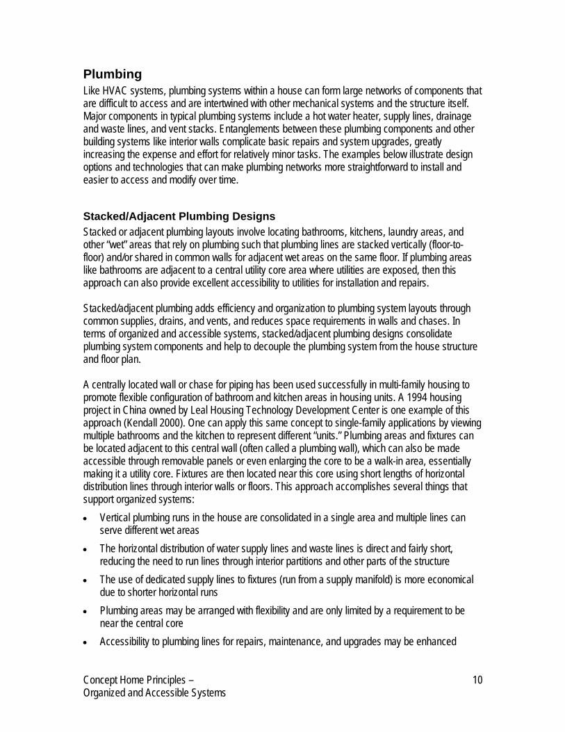
Plumbing Manifolds Plumbing manifolds are units designed to distribute water to multiple fixtures with dedicated hot and cold supply lines while also providing stable pressures and temperatures. These systems can help to organize plumbing systems by providing each fixture with a dedicated hot and cold water supply line, with individual shut-off valves for each line. This arrangement helps
Concept Home Principles – 12 Organized and Accessible Systems

organize the plumbing system and simplifies plumbing repairs and upgrades. Lines on the manifold can even be labeled according to the fixture they serve, similar to the way in which electric panels can indicate the destination of each circuit. Manufacturers like Vanguard, which manufacturers the MANABLOC Manifold, also claim that manifold systems conserve water and energy and provide hot water faster. The MANABLOC system is designed to work with PEX flexible water piping, as shown in the image.
One drawback of using a central manifold and dedicated supply lines to each fixture is the additional tubing material required for this layout. A variation of a central manifold with dedicated lines to each fixture is a system of smaller manifolds located in each plumbing area. Using this approach, each plumbing area (e.g., bathroom) is fed by a dedicated hot and cold supply line, which is distributed to fixtures in the room via a smaller manifold. Manufacturers such as Hepworth (www.hep2o.co.uk/index.cfm) make small 2- and 4-port manifolds that could be used in this application. While this approach requires more manifolds, it reduces piping runs from the central manifold while still providing the benefits of a manifold system. Accessible manifolds within a plumbing area can also offer potential for additional fixtures to be added in the future if extra ports are provided on the manifold.
Modular Plumbing Connections Modular plumbing connections allow for simpler installation of plumbing connections and can help to create systems that can be more readily repaired, upgraded, or reconfigured. While typical plumbing connections require the use of tools and special materials, often in tight spaces like under a sink, products like Moen’s Hydrolock (www.moen.com) simplify the connection of supply lines to faucet fixtures. The Hydrolock component, which was recently introduced to the retail plumbing market, clicks when it is properly snapped together. According to Moen, benefits include faster faucet installation, reduced labor time, no risk of cross threading, and elimination of the need to use tools. The component has a dual O-ring seal to reduce the possibility of leaks, and has a burst resistance of 1,321 psi and a pull resistance of 184 lbs.
Hydrolock Connection Component Image Source: Moen Inc. (www.moen.com)
A similar product designed for easily formed piping connections is manufactured by Sea Tech (www.seatechinc.com). SeaTech’s 24 Series quick connect fittings connect directly to a variety of copper, plastic, and CPVC piping to form connections in a matter of seconds. Series 24 quick connect fittings are suitable for contact with drinking water and are currently used in plumbing, water filtration, and aquarium applications. The fittings are produced in standard imperial inch sizes, and allow for connections to be formed without compression sleeves, adhesives, welding, or clamps. Sea Tech lists manufactured and modular housing among its applications for its PEX tubing and its fitting products.
Concept Home Principles – 13 Organized and Accessible Systems

Flexible Natural Gas Supply Lines Routing natural gas lines in houses typically requires the use of rigid iron pipe that is installed piece by piece from the source to the end use appliance. This can result in utility entanglements when two different system components need to be run through the same space. Corrugated stainless steel gas tubing (CSST) consists of a continuous, flexible, stainless steel pipe with an exterior polyethylene covering. CSST is most often installed in a central manifold configuration (also called parallel configuration) with "home run" lines that extend to gas appliances.
SeaTech quick connect fittings Image Source: Sea Tech Website (www.seatechinc.com)
Manufacturers like Gastite (www.gastite.com/pages.php3) claim that flexible gas piping is lightweight and requires fewer connections than traditional rigid piping because it can be bent easily and routed around obstacles. This flexibility translates to reaching end use appliances more easily, like upstairs fireplaces and dryers, island ranges, and even gas grills on decks. CSST is easy to expand and to use in retrofits where frequent bends and turns are necessary. According to the Gas Technology Institute1, labor savings can range from one-quarter to two-thirds on new construction projects and almost three-quarters on remodeling projects, which can help offset CSST’s higher material costs. Flexible gas piping is also clearly marked as fuel gas piping to reduce any misidentification issues.
Air Admittance Vents (AAVs) Plumbing vent stacks in houses allow air to be drawn into drain systems when they are under negative pressure (e.g. flushing) to equalize the pressure and maintain the water seal in traps. The water seal in traps prevents the introduction of sewer gases into the house. Plumbing vent stack systems are typically constructed with a network of plastic pipes from drains that terminate above the roofline of a house. This network of vent pipes is run in wall systems and through the roof, creating mechanical lines in hidden spaces as well as one or more roof penetrations. Air admittance vents are mechanical devices designed to maintain trap seals without the need for additional vent piping. They are one-way valves that open only under negative pressure (created when a toilet is flushed or a drain stopper is opened). When the water flow stops the valve closes, preventing the escape of sewer gasses under conditions of equal or positive pressure. AAVs are typically made from polyvinyl chloride (PVC) plastic materials with ethylene propylene diene monomer (EPDM) rubber valve diaphragms. Vents come in two sizes: one for fixture venting and a larger size for system venting. They fit standard diameter pipes, ranging from 1-1/4 to 4 inches. Air admittance valves have been effectively used in Europe for more than two decades.
1 As referenced on ToolBase Site: www.toolbase.org/tertiaryT.asp?DocumentID=2079&CATEGORYID=1093
Concept Home Principles – 14 Organized and Accessible Systems

Air Admittance Vents
Image Source: ToolBase Website (www.toolbase.org) For plumbers and contractors, AAVs afford more efficient installations and reduce the amount of venting materials needed by 25 to 75 percent, according to manufacturer estimates. AAVs eliminate the need for lateral return vent runs that require cutting several holes through wall studs, or long runs of vertical piping that must pass through the walls, the attic, and the roof. Fewer bends and tee connections are required, and there is no need to cut, flash, and seal a hole through the roof deck. AAVs also offer flexible solutions for venting kitchen islands, or fixtures connected to walls underneath open living spaces on the floor above. Remodelers can more easily change layouts or vent bath and kitchen additions without disturbing existing living space. The ability of AAVs to reduce mechanical system runs supports the Concept Home principle of organized and accessible systems in homes. Issues to consider when using AAVs may include code approval and contractor familiarity with the product.
Electrical/Communications Electrical and communications networks within houses typically make up the most extensive utility within a home in terms of the number of outlets and length of supply lines. Electrical power outlets, switches, power supplies to appliances, telephone, cable, and networking combine to create dozens of end points in an electrical system with extensive cabling installed in floors, walls, and ceilings. The challenges for creating organized and accessible electrical/communications systems include efficient installation, providing access for repairs and upgrades, and reducing entanglements between the electric system and other utilities and the floor plan. In fact, traditional electrical layouts are heavily intertwined with interior and exterior walls as well as floor systems, where they become integrated with other parts of the house and difficult to access. Strategies to alleviate this entanglement may involve making traditional wiring pathways more accessible, removing them from walls entirely, or even using wireless systems where possible. Several technologies that support these strategies are discussed on page 16.
Concept Home Principles – 15 Organized and Accessible Systems

Prefabricated Wiring Chases in Wall Panels One method of organizing home wiring and providing long-term access is the use of wiring chases that are designed as part of the wall system. Bensonwood Home’s Open-Built® Baseboard System (www.bensonwood.com/services/index.html) offers a good example of open, accessible wiring chases that are prefabricated into the home’s factory-built urethane core wall panels. This approach simplifies the on-site electrical rough-in and keeps wiring accessible for repairs, upgrades, and remodeling. Once the wall panels are set and connected to Bensonwood’s timber frame, wiring can be run in the recessed chase at the base of the wall panels. The chase is 1.5 inches deep and 6 inches high, and the chase can also be designed to provide separation between electric and communications cabling. Once wiring is in place and baseboard outlets are installed, the baseboard trim covers the chase and is held in place with a cap piece that is screwed to the wall panel.
Prefabricated wiring chases in Bensonwood’s factory-built walls Image Source: Bensonwood Homes Website (www.bensonwood.com)
Structural Insulated Panels (SIPs) wall panels are also formed with prefabricated wiring chases. During the fabrication of SIP wall panels, 1.5 inch diameter vertical and horizontal wiring chases are cored through the EPS before the panel lamination process. Manufacturers such as Porter Corp (www.portersips.com) design SIP wall panels with horizontal chases at a height of 16 inches and 44 inches, for receptacles and switches, respectively. Vertical chases allow for vertical wire runs through the wall panel to reach wall switch locations. As the SIP wall panels are erected on site, the builder must drill through the sill and top plates to provide access to the vertical chases. Horizontal drilling through connecting splines may also be required to maintain the continuity of horizontal wire chases. The electrical rough-in is performed by pulling wiring through the chases. The interior OSB has markings to indicate the location of the chases to simplify installation. A variation of prefabricated wiring chases is to go one step further and actually install wiring in the wall panels in a factory setting. This requires more rigorous planning on the part of the builder and electrician, but offers benefits such as a well organized electrical layout and reduced on-site installation time. One detail that arises with pre-wired wall panels is connecting the wiring in adjacent wall panels as they are set on-site. One approach to making these connections in the field is the use of modular electric connectors. The image shows a quick connector used by Bensonwood Homes, which is developing pre-wired wall systems for their homes.
Concept Home Principles – 16 Organized and Accessible Systems

Electrical Raceways Electrical raceways provide a potential solution to wiring access within a home. There are many different types of electrical raceways available, with most types being surface mounted systems that run along the floor or up the side of the wall. These raceways are convenient for adding or changing the location of electrical/communications equipment, but their outward appearance is sometimes a concern to homeowners. An alternative approach is the use of raceways that are hidden by integrating them into trim or walls. One example product is Wire Tracks (www.wiretracks.com), which has designed several hidden raceway products to provide ongoing access to wiring conduits in a home. The WireTracks NC product consists of an interlocking wiring channel with cover with the same thickness as wallboard. The channel is installed against the wall studs, with gypsum then installed above the channel (see image). The channel attaches directly to the studs and includes cable clips to hold the wiring in place. The channel cover attaches to the baseboard molding and they become an integrated unit that can be removed and reattached any time new wiring is needed. WireTracks also makes a crown molding product for wiring runs at the top of walls.
Modular connector for pre-wired wall panels Image Source: Bensonwood Homes
Wire Tracks NC product schematic Image Source: Wire Track Website (www.wiretracks.com)
Whether surface mounted or hidden raceway systems are applied, issues that should be considered include routing through corners, navigating around doorways and windows, and the overall number of pieces required for an installation. Several of these challenges were referenced in the Susquehanna Prototype House project (Lee).
Concept Home Principles – 17 Organized and Accessible Systems

The potential advantages of raceway systems include long-term access to wiring, reduced physical interdependencies with interior walls, and the ability to add new wiring conveniently.
Busways Busways are typically used in the commercial and light industrial markets as a method to supply power during quick floor changes and workstation additions. Manufacturers claim that busways provide access to power distribution instantly, with no need to shut down the main power source. Busways may be ceiling-mounted, recessed, or suspended from ceilings using hanger rods. Most busway housings are provided in sections of varying length, and eliminate the need for most screws, welds, flanges, painting, and removable access covers. In addition to conventional jointed conductor systems, coils of joint-free conductors and insulator strips are available. According to manufacturers, the installed cost of busway systems is equal to or lower than conventional conduit and wire. Busways can also provide additional benefits like flexibility for adding or relocating electrical connections, higher amperage, fewer conduit home runs, and reusability.
Starline Track Busway Image Source: Universal Electric Corp.
www.uecorp.com
Starline Track Busway (www.uecorp.com) has a simple turn-n-lock system that provides access to power distribution instantly. The Starline Track Busway system provides conductors of solid copper, continuous insulators, a continuous access slot, extruded aluminum housing, a ground conductor included in the system, and the choice of various plug-in units.
Flat Wiring Flat wiring offers another option for making wiring accessible or for adding wiring to an existing home without running wires through partitions. One example is DeCord™--a thin, flexible wire that
will allow electricity to be routed along walls and ceilings. When used with “DePlug,” the power source for this flat cable can be a normal room wall outlet. DeCord™ is a 110/220 VAC cord made in 14, 16, and 18 gauge equivalences. It is rated for 15 or 20 amps and has a thickness of 8 mils. The manufacturer of DeCord™, Decorp (www.decorp.com), claims that the use of its thin power cord to supply power to wall and ceiling locations can provide a low-cost and safe alternative to expensive wiring jobs. The product is currently completing development and testing, according to the manufacturer, and is forecast to be released in late fall of 2005.
Flat wire product for conducting audio, video, or dataImage Source: PATH Website (www.pathnet.org)
Concept Home Principles – 18 Organized and Accessible Systems

Decorp also manufacturers flat wire products for audio and video applications. Like the DeCord™ product, the audio and video flat wire products are designed to be integrated with traditional wiring and components through adapters and connectors. The speaker wire, which is currently available, meets Underwriters Laboratories standards; several other Decorp products are currently in the process of gaining UL approvals. Decorp is also developing flat wiring for data transmission that will support applications like home networks. Decorp’s products utilize ultra-thin parallel conductors that are insulated on both sides by a polyester film. The flat wire products are installed on walls and ceilings by applying the cable onto a surface adhesive applied to the wall, covering the surface with a mesh tape, and then applying drywall compound over the mesh and applying the wall finish (paint, wallpaper).
Wireless Doorbell and Alarm Systems Wireless doorbells and alarm systems enhance organized systems by creating building systems that do not rely upon hard wired components. Manufacturers of these systems claim that they can be installed in a matter of minutes. Door chimes can be used to notify the homeowner when visitors have arrived, and they can also let him know when a door has been opened. Alarms and chimes come in a variety of shapes and sizes and offer many sound options. Security alarms have contact sensors that can be placed on windows and doors as well as motion detectors for rooms and hallways. Batteries and AC adapters typically power these systems, so their power supply is completely independent of the house or relies upon a wall outlet. The wireless signal operating range can reach well over a 100-ft radius, and alarm systems can also be connected to a phone line for monitoring or to automatically dial stored numbers.
Lighting Lighting systems in houses typically consist of wall- and ceiling-mounted fixtures connected to one or more wall-mounted switches. Like the other mechanical systems discussed above, these systems rely on routing lines through wall cavities and ceiling systems. While changing a light fixture can often be accomplished relatively easily, relocating or adding new switches or fixtures present challenges. Further, during major floor plan renovations when partitions may be relocated, wiring run inside wall cavities or ceilings must be addressed.
Wireless Lighting Controls Wireless lighting controls are another innovation that can help improve the organization and accessibility of home lighting systems. Wireless controls for electrical outlets and wall switches are currently available for residential applications. These controls use a relay to allow for wireless control of lights, appliances, and other plug loads. These components are typically placed between the live loop and the light fixture or plug load, and are controlled with a wireless remote (e.g., the switch). Such systems can eliminate the need to run wires to wall switches, which provides installation benefits, eases utility entanglements, and helps decouple electrical lines from interior walls. Piezoelectric switch devices are also available, which generate their own power and alleviate the need for batteries in the wireless switch.
Concept Home Principles – 19 Organized and Accessible Systems
At the University of California at Berkeley’s Center for the Built Environment (www.cbe.berkeley.edu), research is currently underway to develop a prototype wireless lighting control system. The objective of the research is to develop a flexible and programmable wireless lighting control system that can be used for both retrofit and new construction. Key system features include:
• Wireless switches that can be programmed to operate any combination of power relays (and light fixtures)
• An inexpensive power relay and a wireless mote installed in each light fixture, which is controlled by a wireless switch.
• Compatibility with existing lighting systems, which means that existing lighting ballasts will not require replacement
Once the system is installed, each switch can be programmed to change which fixtures it controls without any hardware changes. Switches can be mobile handheld devices or can be attached to a wall for a central location accessible to multiple users. This system is primarily targeted for commercial applications where wireless and programmable control schemes on larger lighting systems can provide energy savings and greater occupant control over their environment. (In a pilot installation of the lighting control prototype, building occupants used 40% less lighting energy when they were given individual control of lights in their workplace.) However, the wireless aspect of the system and the ability to reprogram wireless controllers without hardware changes are attractive concepts to support rationalized lighting systems in homes.
Remote Source Lighting Remote source lighting is a potential technology that could improve the flexibility of residential lighting systems. This technology separates the light source from the area that is illuminated, and offers the ability to light multiple locations with a single light source. The conduits that distribute light from the central source may be fiber optics or prism light guides. Fiber-optic systems are already used extensively in non-illumination applications such as data communications, while prism light guides are relatively new and not yet common. In the 1990s, the use of remote-source lighting steadily increased. Current applications for remote source lighting include displays in museum and retail settings, lighting in wet and underwater areas, and architectural accent lighting. Remote source lighting offers a number of unique operating characteristics. These systems do not contain electrical parts in the light guides, and can be effective solutions for lighting in hazardous areas, like spaces with explosive gases or water. Also, the light guides do not produce electromagnetic interference since they carry light instead of electricity. Lighting system maintenance is also simplified by locating the light source in an accessible place, where a single lamp can be changed instead of multiple lamps located at fixtures. The ability to separate the source from the illuminated areas can also be a maintenance benefit in areas with very high light fixtures like atriums.
Concept Home Principles – 20 Organized and Accessible Systems

Image Source: Remote Source Lighting International (www.remotesource.com) For residential applications, remote source lighting could help provide illumination to multiple areas in a house from a single, centralized light source. This arrangement would simplify maintenance and also allow for easier reconfiguration or expansion of light systems. While room lighting in residential applications is currently limited due to cost and technical issues, industry experts feel that remote source lighting will become an increasingly viable alternative as materials improve and costs decrease. Current technical limitations include high light losses: significant losses before light enters the fiber, and losses along the length of the guide (10 percent every 10 feet). Installations must also adhere to radius clearance specifications for the light emitting fibers. More information on remote source lighting can be found from the Lighting Research Center (www.lrc.rpi.edu).
Solid-state Lighting Solid-state lighting, which utilizes semiconducting material to convert electricity into light, offers the potential for new types of light-emitting products which would offer flexible fixture locations and even the integration of lighting into other parts of the home (e.g., a light panel in a wall). Also, with its vastly enhanced durability compared to traditional lighting technologies, solid-state lighting also reduces the need for access to lighting systems because fixtures would not need to be accessed to change bulbs. Solid-state lighting includes light-emitting diodes (LEDs), organic light-emitting diodes (OLEDs), and light-emitting polymers. This technology is the first truly new lighting technology to emerge for nearly 100 years, according to the Lighting Research Center (www.lrc.rpi.edu/index.asp). LED lighting applies electric current to a semiconductor to produce light while producing very little heat, unlike incandescent and fluorescent lighting. LEDs have been in use since the 1960s, but due to their limited capabilities (they could not produce white light) their applications were mostly for indication lighting in electronic devices. In the 1990s the technology developed to the point where LEDs could produce white light, leading to the current focus on improving LED technology for illumination applications. LED lighting offers significant potential benefits such as reduced energy consumption, longer life, improved durability, better quality light (minimal UV and IR radiation), and smaller, more flexible light fixtures that could be formed into panels or other components. According to DOE estimates, which assume an accelerated R&D schedule for this technology, solid-state lighting could displace other general lighting technologies by 2025, resulting in a 29 percent reduction in energy consumption and saving 3.5 quadrillion BTUs.2
2 U.S. Department of Energy. Solid-State Lighting Website, http://lighting.sandia.gov/.
Concept Home Principles – 21 Organized and Accessible Systems

Potential applications for LED lighting in the homebuilding industry include task lighting, under-cabinet fixtures, and pathway and stair lighting. As the illumination technology continues to evolve, the flexibility of LED lighting could make possible entirely new types of “fixtures” – where a “light panel” could be built into a wall or ceiling as opposed to a traditional bulb-based fixture. LED lighting can also be “tuned” to vary the color appearance of the light to fit a room environment or a resident’s preferences. The compact size of LED lighting and the very low heat generation would also permit the integration of lighting into furniture or other surfaces within a room.
Structure In addition to considering the design and technologies used in the major utility systems in a home, the structure of the house also plays a major role in determining the extent of entanglement. For example, two identical looking houses could incorporate different structural layouts and members. One of the houses could incorporate several of the measures discussed below, creating well organized systems and limiting interdependencies between the structure, services, and floor plan. Initial construction of the home would be simplified as a result, as would future repairs and renovations. The second house could be built with no appreciation for entanglements and the complications they cause, and as a result the initial construction and ongoing improvements would be more difficult. Several design considerations that can result in a home more like the first house are discussed below.
Clear-Span Structural Designs A major interdependency between the structure of a home and the floor plan arises when the structure actually becomes part of the floor plan. This is the case when interior partitions serve as sheer walls or load-bearing walls in a house. These interior walls are essentially part of the structure, as they transfer loads to other parts of the house. As the home undergoes mechanical system rough-in and finishing, these load-bearing elements are further used to accommodate mechanical systems like plumbing, HVAC, and electric. Thus, the interior partition with the main purpose of defining a portion of the space plan of the house also becomes integral to the structure and the mechanical systems. The structure, mechanical systems, and floor plan all become intertwined. Clear-span structural designs are support systems for houses that rely solely on exterior walls or columns as the load-bearing members, eliminating the need for load-bearing walls within the floor plan. This approach aids in separating the structure from the floor plan. Designs of this type rely on the depth, spacing, and material type of framing members to transfer loads downward through exterior walls. As a result, interior partitions are not load-bearing elements and are decoupled from the home’s structure. Separating the structure from the home’s floor plan with this approach offers several potential advantages: • Increased design flexibility: builders can design a standard building structure, and then modify
interior floor plans on different units to satisfy buyers’ preferences without major structural implications.
Concept Home Principles – 22 Organized and Accessible Systems
• Simplified remodeling: since interior walls are not load-bearing elements, moving or eliminating partitions does not involve structural implications.
• Open floor plans: clear-spans do not require interior support walls, allowing for open floor plan designs that facilitate larger rooms and maximize the usable floor space within a building.
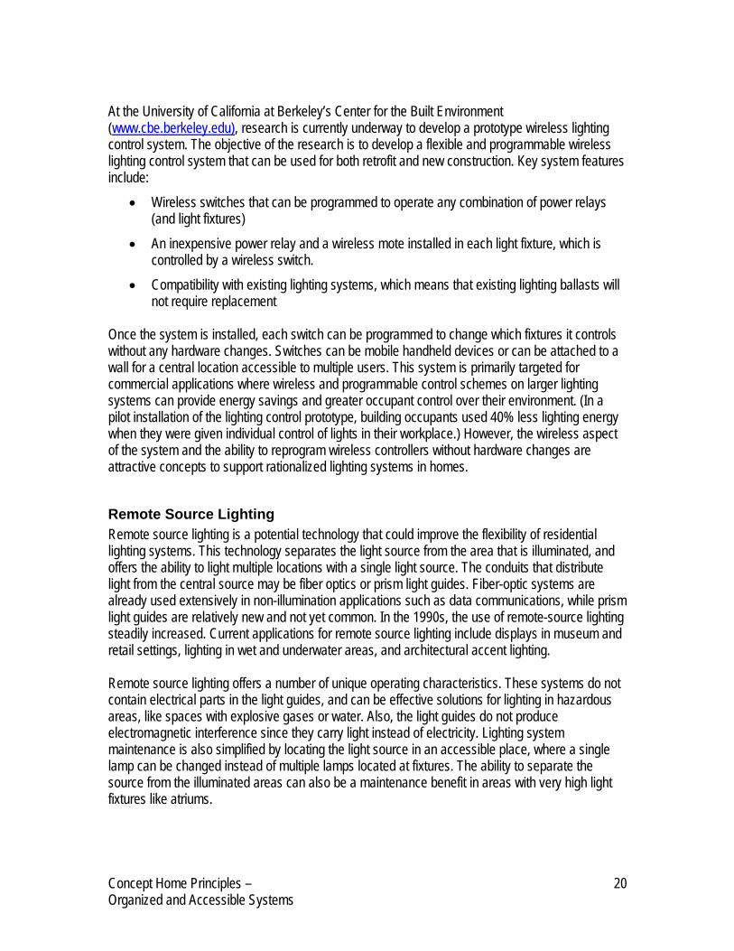
The sections below explore several methods to achieve clear-span structures. Open-Web Floor Joists In addition to the benefits listed above, using open-web floor joists to accomplish a clear-span design can also offer simplified mechanical system installations. Open-web floor joists can provide adequate space for horizontal routing of building systems like plumbing and HVAC. Openings like those shown in the image below can accommodate fairly large mechanical runs. And while this design still combines the mechanical systems with the structure to an extent, this interaction is planned for and organized.
Open Web Floor Joist: At 12” O.C. – this 14” deep floor truss can span > 24’. A similarly sized steel joist at 12” O.C. spans nearly 30’.
Image Source: Universal Forest Products Website (www.ufpi.com)
The Susquehanna Prototype House is a recent research project that illustrated the use of open-web floor joists to achieve a clear-span structure. The Prototype House utilized load-bearing, foam insulated wall panels and clear-span, open-web floor joists. The use of a clear-span structure formed from open-web joists separated the structure, systems, and floor plan in the following ways: • Interior partitions were separated from the structure because of the clear-span floor joists • Mechanical systems like plumbing were routed in the floor system parallel and through the
open-web joists, minimizing and organizing connections between systems and the floor plan
Concept Home Principles – 23 Organized and Accessible Systems
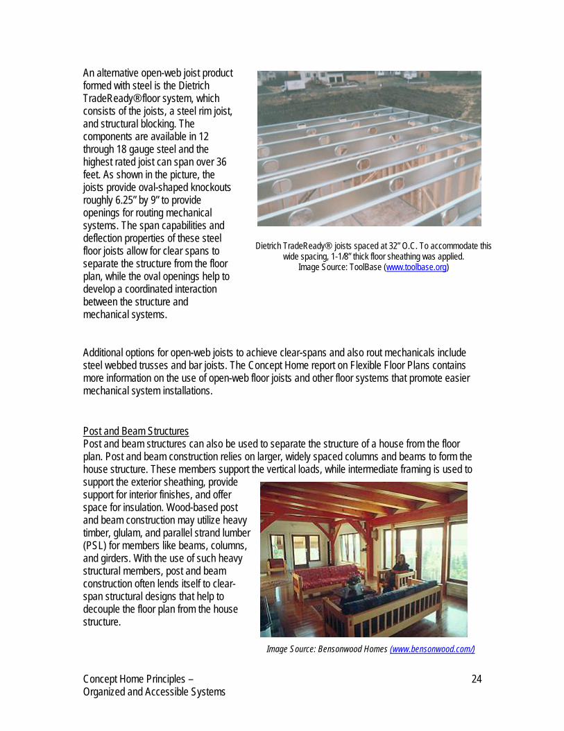
An alternative open-web joist pformed with steel is the Dietrich TradeReady® floor system, which consists of the joists, a steel rim joisand structural blocking. The components are available in 12 through 18 gauge steel and the highest rated joist can span over 36 feet. As shown in the picture, the joists provide oval-shaped knockouts roughly 6.25” by 9” to provide openings for routing mechanical systems. The span capabilities and deflection properties of these steel floor joists allow for clear spans to separate the structure from the floor plan, while the oval openings help to develop a coordinated interaction between the structure and mechanical systems.
roduct
t,
Dietrich TradeReady® joists spaced at 32” O.C. To accommodate this wide spacing, 1-1/8” thick floor sheathing was applied.
Image Source: ToolBase (www.toolbase.org)
Additional options for open-web joists to achieve clear-spans and also rout mechanicals include steel webbed trusses and bar joists. The Concept Home report on Flexible Floor Plans contains more information on the use of open-web floor joists and other floor systems that promote easier mechanical system installations.
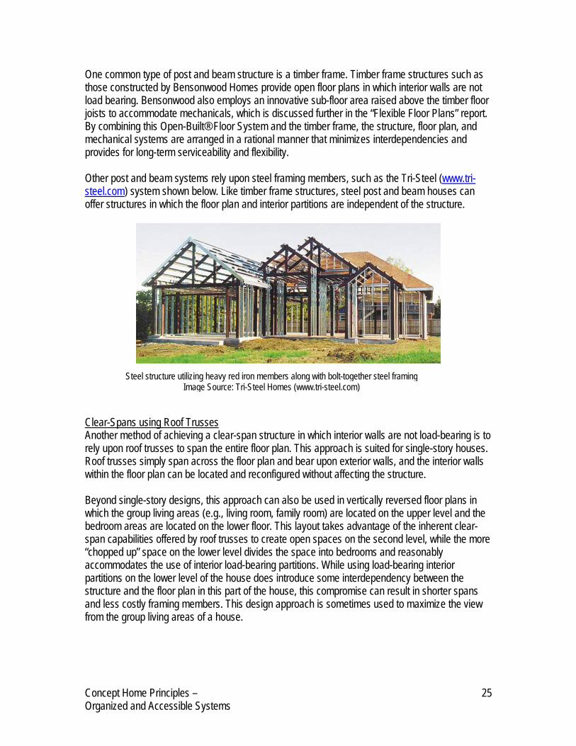
Post and Beam Structures Post and beam structures can also be used to separate the structure of a house from the floor plan. Post and beam construction relies on larger, widely spaced columns and beams to form the house structure. These members support the vertical loads, while intermediate framing is used to support the exterior sheathing, provide support for interior finishes, and offer space for insulation. Wood-based post and beam construction may utilize heavy timber, glulam, and parallel strand lumber (PSL) for members like beams, columns, and girders. With the use of such heavy structural members, post and beam construction often lends itself to clear-span structural designs that help to decouple the floor plan from the house structure.
Image Source: Bensonwood Homes (www.bensonwood.com/)
Concept Home Principles – 24 Organized and Accessible Systems
One common type of post and beam structure is a timber frame. Timber frame structures such as those constructed by Bensonwood Homes provide open floor plans in which interior walls are not load bearing. Bensonwood also employs an innovative sub-floor area raised above the timber floor joists to accommodate mechanicals, which is discussed further in the “Flexible Floor Plans” report. By combining this Open-Built® Floor System and the timber frame, the structure, floor plan, and mechanical systems are arranged in a rational manner that minimizes interdependencies and provides for long-term serviceability and flexibility. Other post and beam systems rely upon steel framing members, such as the Tri-Steel (www.tri-steel.com) system shown below. Like timber frame structures, steel post and beam houses can offer structures in which the floor plan and interior partitions are independent of the structure.
Steel structure utilizing heavy red iron members along with bolt-together steel framing
Image Source: Tri-Steel Homes (www.tri-steel.com) Clear-Spans using Roof Trusses Another method of achieving a clear-span structure in which interior walls are not load-bearing is to rely upon roof trusses to span the entire floor plan. This approach is suited for single-story houses. Roof trusses simply span across the floor plan and bear upon exterior walls, and the interior walls within the floor plan can be located and reconfigured without affecting the structure. Beyond single-story designs, this approach can also be used in vertically reversed floor plans in which the group living areas (e.g., living room, family room) are located on the upper level and the bedroom areas are located on the lower floor. This layout takes advantage of the inherent clear-span capabilities offered by roof trusses to create open spaces on the second level, while the more “chopped up” space on the lower level divides the space into bedrooms and reasonably accommodates the use of interior load-bearing partitions. While using load-bearing interior partitions on the lower level of the house does introduce some interdependency between the structure and the floor plan in this part of the house, this compromise can result in shorter spans and less costly framing members. This design approach is sometimes used to maximize the view from the group living areas of a house.
Concept Home Principles – 25 Organized and Accessible Systems

Organizing Mechanisms “Organizing mechanisms” are packages of components that can be configured to provide design flexibility, installation efficiency, and ongoing adaptability of building systems. This type of technology includes proprietary building systems with specialized components, design tools, and installation procedures, as well as a few systems that rely on commodity products. Several examples follow.
Central Utility Cores One of the main impediments to rationalizing utility systems is the challenge of routing these services throughout a house while minimizing entanglements with the structure and floor plan. One approach to this issue is the use of central utility cores that are used to rout plumbing, HVAC, electrical, and other utilities upwards in a house and to establish rough-in connections to rooms adjacent to the core. Utility cores can help to consolidate and centralize mechanical system components like pipes and ductwork, thereby decoupling systems from the structure and floor plan. If a utility core can be centrally located within a floor plan, many of the mechanical supply lines may also be shortened, which provides for cost savings. The idea of a central core that would route mechanical systems to adjacent rooms in the home can be traced back as far as 1869, in Catharine Beecher’s proposal for an American Woman’s House. This design incorporated a central core to hold the home’s systems, with the other rooms situated adjacent to this core and served by the centralized utilities (Kendall 1994). In a more modern version of a utility core, a prefabricated element with standardized outlets for accepting utility connections for gas, water, electric, and sewer could be installed following foundation work (HUD 2004). The core would offer a central connection point for utility feeds into the home and also permit vertical routing of these systems. Ongoing access to the core would also allow for efficient upgrades and repair to mechanical systems over time. Key advantages to this approach include the following: • Separation of systems: a central core would reduce physical interdependencies between the
utility systems and the structure by easing vertical distribution and allowing for direct utility connections for rooms adjacent to the core
• Reduced mechanical runs: if a core is centrally located in a floor plan, it can reduce the length of mechanical lines for systems like plumbing and HVAC
• Access: a core designed for ongoing access facilitates repairs and system upgrades • Cost and space savings: in more extensive cores which incorporate HVAC, hot water heater,
and even laundry appliances, concentrating these components in a single area eliminates the need to frame and finish separate areas for this equipment
Development of prefabricated cores to date has included European efforts that focused on multi-family applications. This application offers a more standardized design environment, as the dimensions of living units and the location of utilities tends to be more standardized. Background research on the Concept Home has also indicated that single-family builders in the U.S. have
Concept Home Principles – 26 Organized and Accessible Systems

experimented with prefabricated cores, although no current manufacturing efforts in this area have been identified. Other U.S. builders currently use a site-built utility core that serves much the same function. Such a core can be built and developed as part of the normal construction cycle, but the core area remains open and accessible throughout construction and when the home is completed. Site-built cores of this type can also be enlarged such that they also incorporate other mechanical equipment like the washer and dryer.
Matura Infill System The Matura Infill System is a patented system comprised of a base floor tile (called Matrix Tile), a track that integrates into the top of the floor tile to form a bottom track for partitions (called Base Profile), and design software that supports production, prefabrication, and installation. Although the application of this infill system is primarily intended for multi-family buildings, the individual technologies that make up the system illustrate possibilities for single-family applications. The word “infill” represents systems, components, and fixtures within the building such as HVAC, electric, plumbing, and cabinets. Integrated infill systems typically include the distribution components for these systems (e.g., pipes, wires), as well as components that allow for routing these distribution components in a manner that minimizes entanglements with the building structure. Matura’s Matrix Tile component is applied to the sub-floor of a building. This specially designed tile provides pathways to horizontally distribute plumbing lines, electrical and communications wiring, and ductwork. The tile also accommodates zero-slope gray water drain lines as well as dedicated water supply lines in pre-formed grooves in the tile. On top of the Matrix Tile, the Base Profile component integrates into the tiles and serves as the base for interior partitions. In addition to joining wall partitions to the floor tiles, the Base Profile also includes a wiring chase for baseboard wiring runs and receptacles. Together, the Matrix Tile and Base Profile incorporate 23 different subsystems.
Image Source: Residential Open Building, by Stephen Kendall and Jonathan Teicher
Concept Home Principles – 27 Organized and Accessible Systems
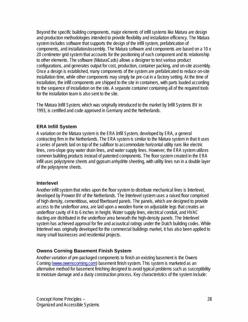
Beyond the specific building components, major elements of infill systems like Matura are design and production methodologies intended to provide flexibility and installation efficiency. The Matura system includes software that supports the design of the infill system, prefabrication of components, and installation/assembly. The Matura software and components are based on a 10 x 20 centimeter grid system that accounts for the positioning of each component and its relationship to other elements. The software (MaturaCads) allows a designer to test various product configurations, and generates output for cost, production, container packing, and on-site assembly. Once a design is established, many components of the system are prefabricated to reduce on-site installation time, while other components may simply be pre-cut in a factory setting. At the time of installation, the infill components are shipped to the site in containers, with parts loaded according to the sequence of installation on the site. A separate container containing all of the required tools for the installation team is also sent to the site. The Matura Infill System, which was originally introduced to the market by Infill Systems BV in 1993, is certified and code approved in Germany and the Netherlands.
ERA Infill System A variation on the Matura system is the ERA Infill System, developed by ERA, a general contracting firm in the Netherlands. The ERA system is similar to the Matura system in that it uses a series of panels laid on top of the subfloor to accommodate horizontal utility runs like electric lines, zero-slope gray water drain lines, and water supply lines. However, the ERA system utilizes common building products instead of patented components. The floor system created in the ERA infill uses polystyrene sheets and gypsum anhydrite sheeting, with utility lines run in a double layer of the polystyrene sheets.
Interlevel Another infill system that relies upon the floor system to distribute mechanical lines is Interlevel, developed by Prowon BV of the Netherlands. The Interlevel system uses a raised floor comprised of high density, cementitious, wood fiberboard panels. The panels, which are designed to provide access to the underfloor area, are laid upon a wooden frame on adjustable legs that creates an underfloor cavity of 4 to 6 inches in height. Water supply lines, electrical conduit, and HVAC ducting are distributed in the underfloor area beneath the high-density panels. The Interlevel system has achieved approval for fire and acoustical ratings under the Dutch building codes. While Interlevel was originally developed for the commercial buildings market, it has also been applied to many small businesses and residential projects.
Owens Corning Basement Finish System Another variation of pre-packaged components to finish an existing basement is the Owens Corning (www.owenscorning.com) basement finish system. This system is marketed as an alternative method for basement finishing designed to avoid typical problems such as susceptibility to moisture damage and a dusty construction process. Key characteristics of the system include:
Concept Home Principles – 28 Organized and Accessible Systems

• Wall panels with a rigid fiber glass core (R-11, 95 noise reduction coefficient) instead of traditionally installed gypsum. The panels are easily removed for access to foundation walls and utilities, and are designed to be vapor permeable to let the wall dry toward the inside
• A dent-resistant, pre-finished surface on the wall panels and prefabricated channels to hold panels in place.
• A bottom track to the wall system that offers space to rout low voltage wiring. The Owens Corning basement finish system can be installed relatively quickly (an average of two weeks) and cleanly, so the household is not disrupted while construction is taking place. The removable panels promote the principle of organized systems by allowing the wiring and foundation to be easily accessed whenever necessary3.
Other Infill System Examples With the exception of the Owens Corning system, the organizing mechanism products described above were generally intended for multi-family and/or commercial building applications, although many aspects of these systems could also hold potential benefits for rationalized utilities in single-family houses. When considering the application of infill systems to single-family dwellings in the U.S., one of the major implications to consider is the shift in design, fabrication, and installation practices that accompanies an integrated infill approach. Compared to typical site-built construction approaches, changes would be required in scheduling, subcontractor responsibilities, material selection, installation methods, code approval, and customer education. The Matura, ERA, and Interlevel examples above were drawn from the book Residential Open Building (Kendall 2000), which provides numerous project case studies involving infill systems as well as short reviews of several systems. A few further examples of infill systems drawn from this resource are summarized in the table below, including highlights of those features that support organized and accessible systems. It should be noted that some of these efforts were research-based or experimental initiatives, and that some of the specific products or projects may no longer be underway.
Infill System Organization/Location Key Features Espirit Espirit
Consortium*/Netherlands • Raised floor systems in bathrooms • Specially designed traps for showers, tubs • Quick connects for bathroom fixtures (supply and drain lines),
water supply lines, and heating pipes • Low-slope drain lines • Surface-mounted and partition chase distribution of power and
data communications • Integrated pipes in the back of kitchen cabinets • Demountable wall partition system
3 Owens Corning Basement Finish System: http://www.owenscorning.com/around/bfs/features.asp
Concept Home Principles – 29 Organized and Accessible Systems
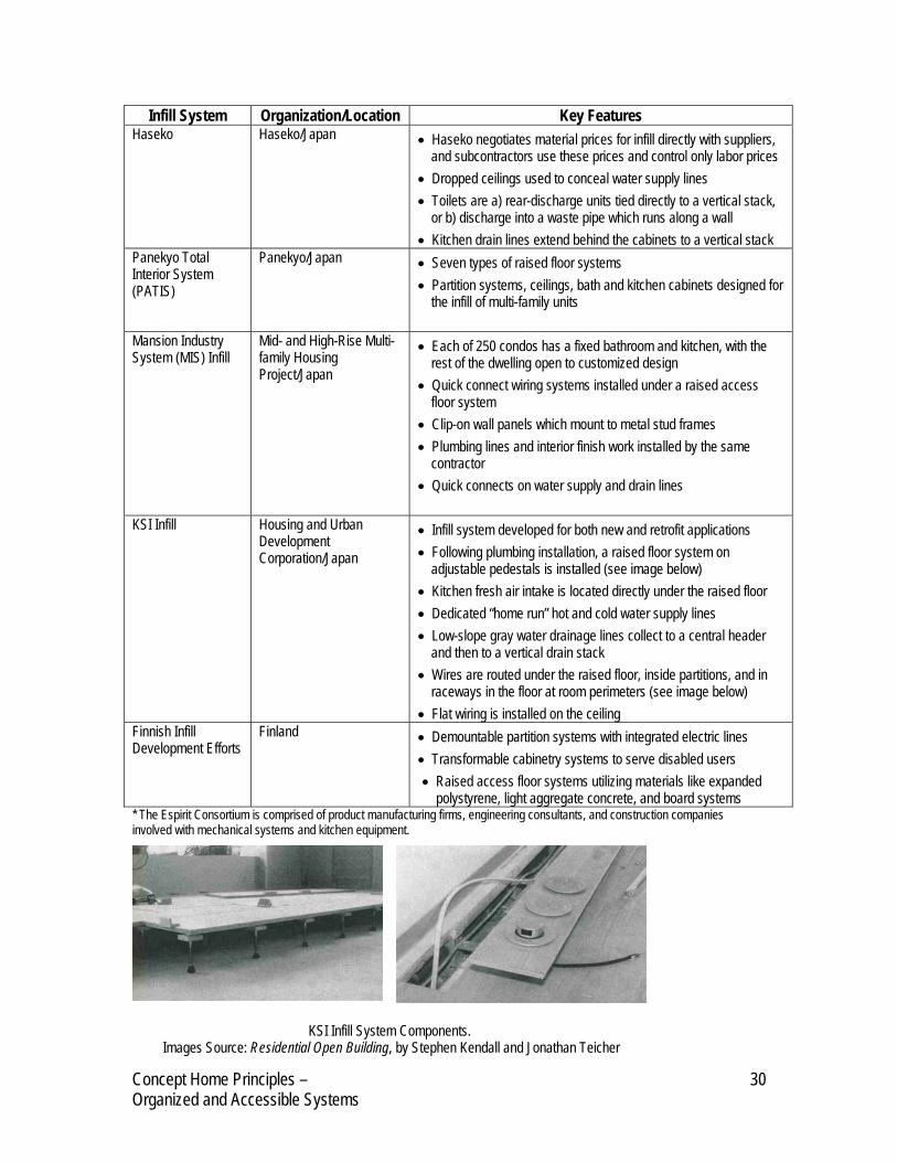
Infill System Organization/Location Key Features Haseko Haseko/Japan • Haseko negotiates material prices for infill directly with suppliers,
and subcontractors use these prices and control only labor prices • Dropped ceilings used to conceal water supply lines • Toilets are a) rear-discharge units tied directly to a vertical stack,
or b) discharge into a waste pipe which runs along a wall • Kitchen drain lines extend behind the cabinets to a vertical stack
Panekyo Total Interior System (PATIS)
Panekyo/Japan • Seven types of raised floor systems • Partition systems, ceilings, bath and kitchen cabinets designed for
the infill of multi-family units
Mansion Industry System (MIS) Infill
Mid- and High-Rise Multi-family Housing Project/Japan
• Each of 250 condos has a fixed bathroom and kitchen, with the rest of the dwelling open to customized design
• Quick connect wiring systems installed under a raised access floor system
• Clip-on wall panels which mount to metal stud frames • Plumbing lines and interior finish work installed by the same
contractor • Quick connects on water supply and drain lines
KSI Infill Housing and Urban Development Corporation/Japan
• Infill system developed for both new and retrofit applications • Following plumbing installation, a raised floor system on
adjustable pedestals is installed (see image below) • Kitchen fresh air intake is located directly under the raised floor • Dedicated “home run” hot and cold water supply lines • Low-slope gray water drainage lines collect to a central header
and then to a vertical drain stack • Wires are routed under the raised floor, inside partitions, and in
raceways in the floor at room perimeters (see image below) • Flat wiring is installed on the ceiling
Finnish Infill Development Efforts
Finland • Demountable partition systems with integrated electric lines • Transformable cabinetry systems to serve disabled users • Raised access floor systems utilizing materials like expanded
polystyrene, light aggregate concrete, and board systems * The Espirit Consortium is comprised of product manufacturing firms, engineering consultants, and construction companies involved with mechanical systems and kitchen equipment.
KSI Infill System Components. Images Source: Residential Open Building, by Stephen Kendall and Jonathan Teicher
Concept Home Principles – 30 Organized and Accessible Systems
Conclusion Many opportunities exist to improve the organization and accessibility of residential mechanical systems. This report highlights numerous technology-based solutions, while complementary Concept Home reports highlight design techniques. A full review of the ideas contained in these reports reveals many individual solutions, but to realize significant gains in rationalized utilities a combination of appropriate techniques must be employed. As this project moves ahead to develop Concept Home plans and specifications, such combinations will be assessed based on their contribution to organized utilities, as well as their impacts on other key considerations like cost, design, and marketability.
Concept Home Principles – 31 Organized and Accessible Systems

Reference List California Energy Commission, “Home Builders Guide to Ducts in Conditioned Space – Design Guidelines,” 2003. Joint Center for Housing Studies of Harvard University, “The Changing Structure of the Home Remodeling Industry.” 2005. Kendall, Stephen. “The Entangled American House,” Blueprints, Vol. XII, No. 1, 1994. Kendall, Stephen and Teicher, Jonathan. “Residential Open Building.” E & FN Spon, London, 2000. Lee, Stephen. “Demonstrating Design for Flexibility in the Susquehanna Prototype House,” Center for Building Performance and Diagnostics, Carnegie Mellon University. Ruiz, Fernando Pagés. “Building an Affordable House: Trade Secrets to High-Value Low-Cost Construction.” Newtown, CT: Taunton Press, 2005. U.S. Department of Housing and Urban Development. “Durability by Design – A Guide for Residential Builders and Designers,” May 2002. Available on HUD User: www.huduser.org U.S. Department of Housing and Urban Development. “Organizing Residential Utilities: A New Approach to Housing Quality,” November 2004. Available on HUD User: www.huduser.org
Concept Home Principles – 32 Organized and Accessible Systems