optimizing thermal comfort considerations with electrical...
TRANSCRIPT

Technical Note
Optimizing thermal comfortconsiderations with electricaldemand response programimplementation
Sama Aghniaey1, Thomas M Lawrence1,Javad Mohammadpour1, WenZhan Song1, RichardT Watson2 and Marie C Boudreau2
Abstract
Maintaining thermal comfort within an occupied building requires energy; thus, optimized solution meth-
ods for balancing energy use with indoor environmental quality (adequate thermal comfort, lighting, etc.)
are needed. Current building temperature control systems do not adequately take in account the adaptive
capability of the occupants, but this concept can be used advantageously during implementation of demand
response. Demand response programs can affect both the occupants’ thermal comfort from temporary
adjustments to space temperature settings. This paper describes ongoing research and field testing of
methods to optimize building energy consumption for heating, ventilation and air conditioning applications
accounting for human factors such as the thermal comfort by the occupants. Model predictive controllers
could serve as powerful tools to optimize the operation of smart buildings and improve human comfort
perceptions while helping to better integrate renewable energy systems with increased grid stability.
Practical application: This work outlines how the operation of cooling systems can be optimized with
respect to reducing peak demand while still maintaining thermal comfort within acceptable ranges.
Keywords
Demand side management, HVAC systems, human comfort
Introduction
The advent of a smart grid opens the potentialfor smart buildings to participate in load man-agement and demand response (DR) programsin collaboration with the electrical utility or gridsystem operator. DR may be used for managingelectrical loads during peak, high-demand peri-ods or for optimized integration of intermittent
1College of Engineering, University of Georgia, Georgia, USA2Management Information Systems, Terry College of Business,
University of Georgia, Georgia, USA
Corresponding author:
Thomas M Lawrence, College of Engineering, University of
Georgia, USA.
Email: [email protected]
Building Serv. Eng. Res. Technol.
0(0) 1–13
! Authors 2018
DOI: 10.1177/0143624417752645
journals.sagepub.com/home/bse

renewable energy sources into the grid. Smartbuildings and the smart grid may not be per-ceived as having a direct impact on the indoorenvironment of buildings, but the interaction ofsmart buildings with a smart grid in areas likeDR programs can affect both the occupants’thermal comfort as well as the building’senergy consumption (and the correspondingenvironmental impacts). For example, maintain-ing thermal comfort within an occupied buildingrequires energy, and therefore optimized solu-tion methods for balancing energy use withindoor environmental quality (adequate thermalcomfort, lighting, etc.) are needed. Currentbuilding temperature control systems do notadequately take into account the adaptive cap-ability of the occupants, which can be usedadvantageously during implementation of DRprograms.
This paper describes ongoing research andfield testing of methods to optimize buildingenergy consumption for heating, ventilationand air conditioning applications, accountingfor human factors such as the thermal comfortby the occupants. We also discuss our vision forhow model predictive control (MPC) techniquescould be employed to optimize the operation ofsmart buildings and improve human comfortperceptions while helping to better integraterenewable energy systems with increased gridstability.
Occupant thermal comfort
Thermal comfort has different definitions fromvarious points of view, but these are all generallyassociated with a thermal balance of the body.1
Thermal comfort has been defined as ‘‘The con-dition of mind which expresses satisfaction withthe thermal environment’’.2 Thermal comfortfrom this view point is extremely subjective,and it is hard to deal with in practical terms.An energetic definition for thermal comfortstates that thermal comfort is reached when‘‘heat flows to and from the human body arebalanced and mean skin temperature andsweat rate are within the comfort range, which
is only dependent on metabolism’’. It could beclearly understood that mean skin temperatureis a dominant factor in both later definitions.3
On the other hand, ‘‘Dissatisfaction maybe caused by the body being too warm or coldas a whole, or by unwanted heating or cooling ofa particular part of the body (localdiscomfort)’’.4
Adaptive versus heat balance thermalcomfort models
Approximately 50 years ago, Fanger proposed aheat balance model to enable predictions of theacceptability of a certain thermal environmentfor a group of people with different activityand clothing levels. The predicted mean vote(PMV) index was developed to be a representa-tive of the ‘‘mean thermal sensation vote for alarge group of building occupants for any givencombination of thermal environmental vari-ables, activity and clothing levels’’.5 The PMVcan be affected by air temperature ta, mean radi-ant temperature tmrt, relative air velocity v, airhumidity Pa, metabolism or type of activity M,and clothing level Icl, as shown in Equation 1below.
PMV ¼ f ta, tmrt, v,Pa,M, Iclð Þ ð1Þ
There is an empirical relationship between thePMV index and the predicted percentage dissa-tisfied (PPD). PPD represents a predicted per-centage of building occupants that would bedissatisfied with the existing thermal environ-ment. Many heating, ventilation and air-condi-tioning (HVAC) standards have been applyingPMV-PPD globally in the built environment,with the thermal comfort zone typically isdefined to fall between a PMV �0.5 and +0.5.
There are two main concepts which arethought to be misrepresented in Fanger’smodel: (a) Thermal neutrality is not equal tothe best thermal comfort since more peoplewould prefer non-neutral condition for theirthermal comfort; and (b) Not all people feel dis-comfort in very high and very low PMVs and a
2 Journal of Building Services Engineering Research & Technology 0(0)

non-negligible number of people would prefersuch a condition.6
Dr. Thomas Bedford published a book in1936 where he proposed an adaptive thermalcomfort model.7 The model was the result offield studies in which occupants in their every-day environment were questioned about theirthermal vote. People in these studies were sub-ject to the regular natural variability of thermalconditions in the spaces, and researcher interfer-ence was minimized. He also measured environ-mental parameters such as temperature andsubjects skin temperature on forehead, palm,and foot. Statistical analysis of these results ledto the development of the adaptive thermal com-fort model method.7,8 In field studies by Nicoland Humphreys,9 the temperature range thatoccupants describe as ‘‘comfortable’’ wasshown to be wider than that of the heat balanceapproach. They related this discrepancy to theadaptive behavior of subjects as the result of afeedback loop between their comfort and behav-ior. Various studies have revealed that the opti-mum temperature of comfort strongly correlateswith the mean temperature that people hadrecently experienced, and the PMV is justweakly correlated with the indoor tempera-ture.10 In summary, what the adaptive approachproposes is that thermal perception is an amal-gam of environmental and personal factors,similar to Fanger’s model, and other more com-plex factors such as ‘‘demographics, context,environmental interaction, and cognition aswell as occupant’s past thermal history’’. Weare working to demonstrate in field studiesthat this concept can be employed to reducepeak energy demand.
Field (real-world) versus climate chamberbased studies
One potential problem is that much of the modelbasis we have for thermal comfort havedepended on experiments done in a climate con-trolled chamber in an invariant thermal condi-tion rather than in ‘‘real-world’’ operationalconditions. However, what happens in the real
world can be much different from that in con-trolled chamber. Our studies described hereinare focused on the typical population thatwould be affected by the zone temperaturechanges that may be implemented as part of aDR or overall energy efficiency measure, and weinclude a commentary on how our results com-pare to other published studies based on field orcontrolled chamber data.
Thermal comfort considerationson DR
Temporarily adjusting HVAC system setpointsis a common method to save on energy con-sumption and peak demand, and these canapply to both the heating and cooling seasons.However, the degree of the setpoint changes cansignificantly impact the thermal comfort percep-tion of the building occupants.
DR in the electrical grid
Electrical energy differs from other types ofenergy (such as liquid fuels) in that the produc-tion and consumption occur essentially simul-taneously. Power grids must be able to providefor the peak demand that typically occurs duringsummer afternoons and early evenings duringthe cooling season. DR is a prevailing practiceto increase power grids stability, minimizing theneed for increased electricity production andtransmission during peak demand periods, usu-ally through load shedding. A smart grid enablesbuildings to respond to a DR signal as well asprovide current operation data to grid oper-ations. Smart buildings (and their associatedcontrols and equipment) are capable of respond-ing to DR requests to manage peak demand.Some response measures may involve adjust-ments in HVAC operational setpoints (such aszone temperatures or supply air flow rates) orlighting, thus potentially altering an occupant’scomfort perception.
DR, while reducing peak demand, overallenergy consumption, and utility costs for cus-tomers can affect the building occupants
Aghniaey et al. 3

physically and psychologically; it might impairtheir comfort, productivity, mood or evenhealth. However, in some cases this reductionin service results in a stable, if not evenimproved, comfort vote and could be consideredan energy efficiency measure.11 An example ofthis potential for improvement with DR is forovercooled buildings that end up with animproved thermal comfort. Building overcool-ing during the summer to avoid humidity prob-lems is a common issue with many buildings, atleast in the United States.12 The detectabilityand acceptability of DR and load shedding viaHVAC system operation adjustments signifi-cantly depends on the rate of load shedding,overall magnitude of the changes, and their fre-quency. However, in most DR practices, stableambient temperatures are reached usually in lessthan one hour after changing the zone controltemperature.
Accounting for thermal comfort in DRprograms
Adjusting the built environment temperature inaccordance to the outside air temperature canreduce energy consumption for HVAC oper-ation since the occupants have already adjustedto these ambient temperatures themselves. Theconsideration of the adverse effect of DR onoccupants’ thermal comfort should be balancedwith the large amount of energy that is con-sumed for conditioning purposes to keep ambi-ent temperature uniform within a narrow range.
The temperature and operational settings forbuilding HVAC systems influence strongly theenergy consumption, but also can significantlyimpact the occupants thermal comfort percep-tions. An early study by Berglund andGonzales13 concluded that a temperature rampof 0.6�C/h from 23 to 27�C would be acceptablefor at least 80% of the occupants as long as thedew point temperature remained below 20�C.Newsham14 studied the effect of simultaneouslight dimming and cooling load shedding onoffice workers and concluded that a steadyincrease in temperature up to 1.5�C from the
normal temperature over a 3 h period (0.5�C/h)is not detectable for office workers, or if detect-able this would be acceptable (in the circum-stances studied).
Case study and results to date
We have discussed above why it is important tounderstand the thermal comfort perceptions ofthe local population with respect to DR pro-gram implementation. The thermal comfort per-ception is also recognized as being a function ofage, activity level, time of exposure, regional cli-matic and cultural considerations, etc. If HVACsystem adjustments are to be made for DR oroverall energy conservation, then it is importantto account for these factors with respect to thepopulation of occupants in the buildings that areinvolved to determine how far adjustments canbe made and the potential energy savings thatmight be achieved in practice. This sectiondescribes our work to do just that.
Thermal comfort survey testing and results
A number of studies have been done over theyears concerning the thermal comfort perceptionof people as a function of various controlledparameters such as temperature, humidity, etc.Most of these studies have been conducted incontrolled laboratory type situations, althoughsome have done so in real-world settings. Sinceperceived thermal comfort and tolerance rangesvary according to the population involved,along with the indoor and outdoor conditionsor seasons, we elected to conduct a field studythat incorporates these factors. Specifically, ourgoal was to assess the thermal comfort percep-tions of a representative sample of participantsoccupying buildings where DR and MPC tech-niques are being developed. Initial results of ourstudy are described in this section.
Methodology. Starting with the summer cool-ing season of 2014, we have been investigatingthe effect of increased setpoint temperature onenergy use reductions and the thermal comfort
4 Journal of Building Services Engineering Research & Technology 0(0)

perceptions of the building occupants during‘‘real-world’’ conditions at the University ofGeorgia. These tests simulated what could bedone on campus during a DR event, andinvolved surveying more than 1500 students,faculties and visitors about their thermal com-fort perceptions during periods when zone tem-peratures had been adjusted. The primary focusof our studies in 2014 and 2015 was on measur-ing the energy savings potential when makingtemporary adjustments to the HVAC system set-tings (zone thermostat setpoint, etc.). Duringthis initial testing, thermal comfort surveys simi-lar to those done in 2016 were conducted to con-firm for the university facility management thatthe level of changes done would be acceptable tothe typical population that occupies these build-ings. In 2016, testing was focused on measuringoccupant thermal comfort response to variouszone temperatures, with the intent on identifyinga more optimal set of standards for temperaturesettings in our campus buildings.
The test subjects were mostly college age stu-dents chosen randomly among those passingthrough or sitting in hallways, classrooms, audi-toriums, dining halls or dormitory rooms.Indoor and outdoor dry bulb temperature andrelative humidity were measured during the test-ing period, and occasionally the correspondingCO2 levels were also recorded. The 2016 thermalcomfort testing also recorded each subject’s age,gender, time of exposure, and type of clothingworn. Each subject was unaware that zone tem-perature adjustment testing was being done untilthey were surveyed.
The 2016 research shifted to a more intensesurvey of occupants in classroom zones wherethe temperature was preselected. Students wereasked to complete verbal questionnaires, andeach class were questioned two times with differ-ent room temperatures each time (in most cases).The subjects were asked to express their thermalsensation based on a seven-point scale specifiedfor ‘‘point-in-time surveys’’ in ASHRAEStandard 55-20132 as cold, cool, slightly cool,neutral, slightly warm, warm and hot (repre-sented by actual thermal comfort vote scores
of �3 through 3, respectively). Subjects werealso questioned about their health status (ifthey felt healthy or sick) and if they had madeany behavioural adjustment to improve theirthermal condition perception (such as makingchanges in clothing level, changing position,having a cold or hot drink, etc.).
Thermal comfort perception studyresults. Data from the survey were analysedand comparisons made of the thermal comfortperception results to trends noted in previouslypublished studies. The actual thermal comfortvotes of students in 12 different classroomswere collected on two separate days and (forthe most part) with different zone temperatures.This allows thermal comfort perception com-parisons using essentially the same studentpopulations for each paired test under differentair temperature conditions. The number of stu-dents in each class section ranged from 18 up to54. Testing was conducted during lateSeptember and early October of 2016 and theaverage difference in zone temperatures betweenthe two test dates for a given classroom or classsection was approximately 1.5�C. Zone air tem-peratures during the testing ranged from 21.5 tonearly 26�C. Figure 1 shows the correspondingtest conditions for the 24 test periods (12 pairedclass tests) on a psychrometric chart. Note thatall but a few of these tests conditions correspondwith the assumed thermal comfort zonedescribed by ASHRAE Standard 55-2013 foroccupants with a clothing level of 1.0 CLO.
Individual data for all students in a class werealso averaged to obtain the actual mean vote(AMV) for a given class section and date. Atotal of 1381 university students were questionedin 46 classrooms (each classroom was ques-tioned two times while in almost all cases airtemperatures were different for each class ses-sions). Figure 2 shows these AMV values forthe initial 12 pairs of tests run in 2016, withthe same classroom and class sections pairingsconnected via a line. Based on the student surveyresponses, for most cases the clothing levels (asmeasured by the CLO factor) did not change
Aghniaey et al. 5

considerably between the two test dates. Theresults show that when classrooms temperatureswere increased the occupant’s thermal comfort(expressed as average AMV) tended to increase,but for most cases remained in the acceptablerange (�0.5<AMV< 0.5). These findings arein line with some other published field studies.15
Three of the class sections, however, did notfollow this pattern and actually resulted inlower AMV values with warmer room air tem-peratures (an indication of the variability in suchsubjective evaluations). These are connectedwith a dashed line. Two of the classroom pair-ings were done at the same temperature and thusgive additional insight into the potential random
variations of this type of survey. For example,one of the class pairings resulted in an AMVvalue decrease from about �0.5 to �1.0 eventhough the room temperature was slightlywarmer during the second test. This discrepancymight be associated with higher ambient tem-perature and humidity levels on those daysthat affect occupant’s CLO and expectation,although other reasons may exist as well.
Figure 3 summarizes the combined results forall 46 pairs of tests conducted. The usual trend isseen with the increase in AMV with the higherindoor air temperatures. In this figure, thesquare dots (#) represent AMV for tests con-ducted with the ambient temperature in the
100
25
20
The analytical method per section5.3.2 is required for humidity ratiosabove 0.012.
15
10
Comfort zone moves left with:Use section 5.3.3for air speeds over0.2 m/s and toincrease the upperoperativetemperature limitdue to elevated airspeed.
Higher clothingHigher metabolic rateHigher radiant temperature
See section 5.3.2 See section 5.3.2
No lower humidity limit.
10 15
1.0 clo 0.5 clozone zone
Comfort zone moves right with:Lower clothingLower metabolic rateLower radiant temperature
20
0.1 m/s air speed
1.2 m/s air speed
25
Operative temperature (°C)(1/2 Dry bulb + 1/2 MRT for still air)
Hum
idity
rat
io (
kg H
2O /
kg D
ry a
ir)
30 35
80
Relative humidity (%)
600.026
0.024
0.022
0.020
0.018
0.016
0.014
0.012
0.010
0.008
0.006
0.004
0.002
0.000
20
40
Wet bulb te
mperature (°
C)
Figure 1. General range of classroom zone temperature conditions for the testing periods compared to ASHRAE
Standard 55 comfort zones.
6 Journal of Building Services Engineering Research & Technology 0(0)

range of 15 to 21�C, the ‘‘x’’ symbols representtests with ambient temperatures between 21 and27�C and the round dots (�) represent testsduring 27 to 32�C ambient conditions.
Figure 4 provides a more detailed breakdownof the frequency of responses for the thermalcomfort votes during testing of the various class-room zone temperatures, with the frequencydefined as the fraction of all respondentsexpressing that particular thermal vote. Onetrend noted with this population of students isthat as outside dry-bulb temperature increases,occupant’s clothing insulation (CLO value)decreases (as generally might be expected). It isassumed from this that outdoor air temperature,by influencing occupants clothing level or byadjusting their expectations, impacts their ther-mal comfort sensation while indoors (althoughthere is no clear and solid evidence of adjusted
expectations in this particular survey). This find-ing is also compatible with previous studies.16–18
Some subjects, although they had not beenquestioned on this topic, mentioned their pref-erence for what would be interpreted as a ‘‘non-neutral temperature’’. This in contrast withFanger’s PMV/PPD model that assumes neutralcondition as the preferred comfort condition.19
This will be the subject of further investigationsto investigate the differences between neutraltemperature, comfort temperature, and alsoacceptable temperature that occupants (at leastin this student population) can tolerateduring DR.
The main point that can be seen fromFigures 2 to 4 is at least an indication ofthe warmest temperatures that can be set with-out ‘‘significant’’ adverse impact on the ther-mal comfort perceptions. Based on this,
Slightly warm
Slightly cool
1
0.8
0.6
0.4
0.2
–0.2
–0.4
–0.6
–0.8
–121.5 22 22.5 23 23.5 24 24.5
Indoor temperature C
Cla
ss a
ctua
l mea
n vo
te (
AM
V)
25 25.5 26 26.5 27
0
Figure 2. AMV versus zone temperature.
Aghniaey et al. 7

2.5
2
1.5
1
0.5
0
–0.5
–1
–1.521.5 22 22.5 23 23.5 24 24.5
Classroom indoor air temperature (C)
Stu
dent
’s a
ctua
l mea
n vo
te (
AM
V)
25 25.5 26 26.5 27
Figure 3. Distribution of AMV versus indoor air temperatures.
0.45
0.4
0.35
0.3
0.25
0.2
0.15
0.1
0.05
21.5–22.5 23.5–24 24–24.5
Classroom air temperature (C)
The
rmal
vot
e fr
eque
ncy
%
25.5
Too coldCool
Slightly cool
Slightly warmWarmToo hot
Just right
26.50
Figure 4. Frequency of individual thermal comfort votes over the range of classroom zone temperatures tested.
8 Journal of Building Services Engineering Research & Technology 0(0)

a temperature of around 25�C seems to beappropriate for this particular population.
Application to DR. Classrooms in the UGAcampus buildings are usually set to operate atzone temperatures between 20 and 22�C.However, the results of our studies revealedthat this temperature could be increased up to26�C without significantly compromising occu-pant thermal comfort. Based on theenergy demand studies described below in thesection titled ‘Estimation of energy reductionswith simulated DR’, we estimate that significantenergy savings (at least 15%) could be achievedwith increasing the zone temperatures bybetween 1.5 and 2�C. More than 16% of theoccupants surveyed mentioned that they hadincluded some sort of adaptive behaviour, andthat is promising evidence for the potential toincrease indoor temperatures even further with-out adversely compromising the occupant’scomfort. Given the results of our thermal com-fort studies in 2016, zone temperature increaseseven higher than that should be possible withinthe campus buildings. Therefore, this measureshould also be considered by the university asan overall energy efficiency practice, ratherthan just a DR measure.
Estimation of energy reductions withsimulated DR
We have conducted several rounds of testing onthe University of Georgia campus to determineor estimate the potential reduction in peak elec-trical demand when temporary changes weremade to the HVAC system operation whenoperating in cooling mode. Such changes tothe building HVAC operation include adjust-ments in the zone and supply air temperatures,and reducing the maximum supply air flow rateprovided by the variable speed fans. Since mostof the buildings on campus are cooled usingchilled water from a district energy system, wehave also tested the ability of this chilled waternetwork to store ‘‘coolth’’ by precooling thewater during off-peak times and then letting
the water temperatures rise a little abovenormal operation during peak periods.
Figure 5 provides a summary of one day oftesting (Wednesday) compared to a baseline ref-erence on the following day (Thursday). Themaximum ambient air temperature and weatherconditions for the two days were nearly identical.The difference between the dotted and solid linesfor the test and baseline days represents theenergy consumption savings. Peak energydemand and total energy consumption werereduced by over 11% each compared to the base-line reference day, as summarized in Table 1.
The energy savings listing in Figure 5 andTable 1 include the combined effect of the chilledwater system supply temperature adjustment andthe zone temperature adjustments, and theresults are impressive particularly concerningthe fact that only a small portion of the condi-tioned space was included in the zone tempera-ture adjustments. This was due to the overalllogistics since a total of about 10 buildings wereconnected to the distribution system at the timeof this test. Based on rough level calculations, weestimated that about 60–70% of the energydemand savings were due to the zone tempera-ture setpoint adjustments (the rest being due tothe chilled water supply temperature changes).Based on these results, we would estimate thatpotential peak demand reductions in the rangeof 20–30% should be possible with this particulardistrict energy plant, depending on the extent ofimplementation of temporary temperaure adjust-ments (where and to what temperature level).
Thermal comfort surveys were also con-ducted during the test and baseline referencedays, and the results indicated no significantchanges in the percentage of people dissatisfied(PPD) from the overall mean votes collectedwith the calculated PPD being only 5.5% onthe baseline day and 5.1% on the test day. TheAMV of the respondents were both very close tothe neutral value of 0, with the test day resultAMV being 0.03 and the baseline day �0.13.This actually represents a slight improvementand is another indicator of the potential forovercooling that occurs in these facilities.
Aghniaey et al. 9
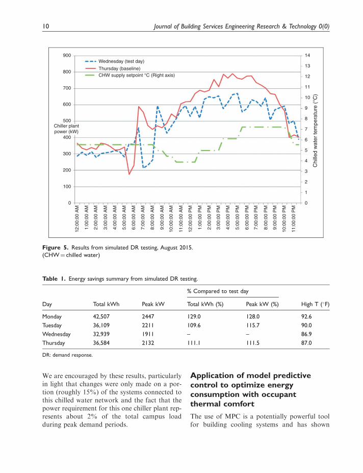
We are encouraged by these results, particularlyin light that changes were only made on a por-tion (roughly 15%) of the systems connected tothis chilled water network and the fact that thepower requirement for this one chiller plant rep-resents about 2% of the total campus loadduring peak demand periods.
Application of model predictivecontrol to optimize energyconsumption with occupantthermal comfort
The use of MPC is a potentially powerful toolfor building cooling systems and has shown
900 14
13
12
11
10
Chi
lled
wat
er te
mpe
ratu
re (
°C)
9
8
7
6
5
4
3
2
1
0
800
Wednesday (test day)
Thursday (baseline)CHW supply setpoint °C (Right axis)
700
600
500
400
300
200
100
0
12:0
0:00
AM
1:00
:00
AM
2:00
:00
AM
3:00
:00
AM
4:00
:00
AM
5:00
:00
AM
6:00
:00
AM
7:00
:00
AM
8:00
:00
AM
9:00
:00
AM
10:0
0:00
AM
11:0
0:00
AM
12:0
0:00
PM
1:00
:00
PM
2:00
:00
PM
3:00
:00
PM
4:00
:00
PM
5:00
:00
PM
6:00
:00
PM
7:00
:00
PM
8:00
:00
PM
9:00
:00
PM
10:0
0:00
PM
11:0
0:00
PM
Chiller plantpower (kW)
Figure 5. Results from simulated DR testing, August 2015.
(CHW¼ chilled water)
Table 1. Energy savings summary from simulated DR testing.
% Compared to test day
Day Total kWh Peak kW Total kWh (%) Peak kW (%) High T (�F)
Monday 42,507 2447 129.0 128.0 92.6
Tuesday 36,109 2211 109.6 115.7 90.0
Wednesday 32,939 1911 – – 86.9
Thursday 36,584 2132 111.1 111.5 87.0
DR: demand response.
10 Journal of Building Services Engineering Research & Technology 0(0)

potential to overcome the challenges whereother control approaches have failed. Thedesign of MPC has been a concept of interestfor a number of years in industry and academiabecause of its ability to yield high performancecontrol systems capable of operating withoutexpert intervention for long periods of time.20
A wide variety of comparisons made recentlyshow that an MPC approach outperformsmost control techniques from different aspectssuch as energy and cost saving, peak load shift-ing, satisfying complicated operational con-straints, improvement in efficiency andtransient response.21–23 From the control pointof the view, MPC could be one of the bettercandidates for supervisory control of buildingcooling systems. The application of MPC tominimize operational cost considering potentialsof active and passive energy storage has beeninvestigated during the past decade.24,25 AnyMPC-based building control must be able topredict efficiently and accurately the change inenergy consumption if a combination of DRmeasures (such as changing set points in someor all of the zones, or supply air temperature andflow rate) are temporarily implemented tohandle DR requests.
One major development challenge that ourwork aims to address is the incorporation ofhuman factors into the MPC scheme. Humans‘‘sensor’’ play a factor in the interaction of thebuilding energy management and control sys-tems with the developing cyber based controls(Figure 6). Peak DR strategies often include
making changes to the building zone tempera-ture set points by temporarily raising them todecrease the overall cooling demand (andhence electrical energy consumption). The fearof causing too much of a temperature swingleading to thermal comfort complaints is oneof the major barriers to maximizing the practicalimplementation of DR measures by facilityoperational staff. A recent paper summarizesthe technical, societal and human factors issuesassociated with connecting smart buildings intoa smart grid.27
We see MPC as a supplement to, not a replace-ment for, existing building energy managementsystems. We see MPC techniques as being mosthelpful when operations that are outside the‘‘normal’’ are desired, for example with participa-tion in automated DR events. TheMPC ‘‘system’’will receive inputs from various informationsources, such as: monitoring of the building(s)operation during the current day and recent his-tory (say the past 24–48h); real-time energy pricesor DR signals; and weather. It also could poten-tially receive input about other systems such asrenewable energy production at the campus orregional level and energy storage system capacity,if installed. MPC output will be the set of recom-mendations for how the individual buildings andtheir equipment should operate based on an opti-mization scheme thatwouldminimize energy peakdemand, overall energy consumption while mini-mizing any negative effects on occupant thermalcomfort perceptions and other building oper-ations. The recommendations would include the
Objective measurements Subjective measurements
PHYSICAL SENSING
SmartMetering and
Buildingdata
Indoor &Outdoor
Environmentaldata
Occupant’sinteraction
with thecontrol system
Occupancydata
Surveyquestionnaires &
self-reporteddata
NON-PHYSICAL SENSING
Figure 6. Integration of building and human cyber systems for energy management. Image taken from Hong et al.
Copyright 2016, Elsevier.26
Aghniaey et al. 11

start and stop times when temporary HVAC setpoint changes would occur and the level of thechanges implemented (which could be differentfor different zones based on predicted occupancyand the occupant population). The MPC outputwould also define other temporary system oper-ation changes such as the chilledwater supply tem-perature set point as outlined with the testingprograms in the previous section. The optimiza-tion could also potentially include the predictedcarbon footprint for that system operation. TheMPC controller is not used to directly controlequipment and systems in the building or set ofbuildings, but rather is an input to the building’senergy management system control as illustratedin Figure 7.
Summary and the way forward
Model predictive control can be used to finetune how buildings are operated. Current oper-ation of the facilities on our university campustends toward overcooling in the summer. Basedon our recent studies, there is a significantpotential for reducing both peak demand totalenergy consumption when the HVAC controlsystems account for the thermal comfort adap-tations of the building occupants.
Declaration of conflicting interests
The author(s) declared no potential conflicts of inter-est with respect to the research, authorship, and/orpublication of this article.
Smart grid: demand response requestsfrom utility or system operator
Currentoperationstatus
Stochastic building loadsInterconnected, distributed generationAutomated demand responseHuman factorsAdaptive learning
SystemMonitoring
Energy systems &buildings operations
Fault detectionand diagnostics
Recent historical data (24-48 hours):
Current day actual record:
Current operation status (for adaptive learning)Key challenges and features:
Forecast data and source:
Recommended system operation(today and the coming 24-48 hours):
HVAC system setpoint scheduleBuilding zone temp. SetpointsEquipment selection
Cost to operate
CO2 footprintTotal energy consumption
Thermal comfort impact
Other operationalrecommendations
Goal is to minimize:Model
predictivecontroller
(which ones operate)
Real time price [Model predicted]Weather (temperature) [Forecast]Building loads [energy models]Building occupancy [Scheduling]Human factors andThermal comfort impacts [Modeling]Equipment operation flag [Input]
Feedback to refine model prdictions (adaptive learning)
Feed forward model inputs
System monitoring, outside agent inputs
Renewable energy production[Correlation model]
Real time priceReal time price signalWeather (temperature, solar)Building loadsEnergy storageRenewable energy production
Real time priceWeather (temperature)Building loadsEnergy storageRenewable energy production
Figure 7. Long-term vision for model predictive control optimization.
HVAC: heating, ventilation and air-conditioning.
12 Journal of Building Services Engineering Research & Technology 0(0)

Funding
The authors wish to thank Georgia Power for theirsupport of this research.
ORCHID iD
Richard T Watson http://orcid.org/0000-0003-0664-8337
References
1. Hoyt T, Lee KH, Zhang H, et al. Energy savings from
extended air temperature setpoints and reduction in
room air mixing. In: International conference on environ-
mental ergonomics, Boston, 2009, http://escholarship.
org/uc/item/28x9d7xj (accessed 25 November 2016).
2. ANSI/ASHRAE Standard 55-2013. Thermal environ-
mental conditions for human occupancy. Atlanta,
Georgia: ASHRAE, 2013.
3. Yang L, Yan H and Lam JC. Thermal comfort and
building energy consumption implications – a review.
Appl Energy 2014; 115: 164–173.
4. Hensen JLM. Literature review on thermal comfort in
transient conditions. Build Environ 1990; 25: 309–316.
5. Fanger PO. Thermal comfort: analysis and applications in
environmental engineering. New York: McGraw-Hill, 1972.
6. Van Hoof J. Forty years of Fanger’s model of thermal
comfort: comfort for all? Indoor Air 2008; 18: 182–201.
7. Bedford T. The warmth factor in comfort at work. MRC
Industrial Health Board Report, No. 76, HMSO,
London, 1936.
8. Brager GS and de Dear RJ. Thermal adaptation in the
built environment: a literature review. Energy Build
1998; 27: 83–96.
9. Nicol F and Humphreys M. Adaptive thermal comfort
and sustainable thermal standards for buildings. Energy
Build 2002; 34: 563–572.
10. Humphreys MA. Field studies of thermal comfort com-
pared and applied. J Inst Heat Vent Eng 1976; 44: 5–27.
11. Motegi N, Piette MA, Watson DD, et al. Introduction to
commercial building control strategies and techniques for
demand response. Energy Environmental Technique
Division, Lawrence Berkeley National Laboratory.
LBNL Report Number 59975, May 2007.
12. Senick JA, Wener RE, Feygina I, et al. Occupant behav-
ior in response to energy-saving retrofits and operations.
Report prepared by the Center for Green Building at
Rutgers University for the Energy Efficient Buildings
Hub, Philadelphia, PA, 2013.
13. Berglund LG and Gonzales RR. Occupant’s acceptabil-
ity of eight-hour-long temperature ramp in the summer
at low and high humidities. ASHRAE Trans 1978; 84:
278–284.
14. Newsham GR, Donnelly CL, Mancini S, et al. The effect
of ramps in temperature and electric light level on office
occupants: a literature review and a laboratory experi-
ment. Volume 4. Summer Study on Energy Efficiency in
Buildings. Washington, D.C.: American Council for an
Energy-Efficient Economy, 2006.
15. Zhang H, Arens E and Pasut W. Air temperature thresh-
olds for indoor comfort and perceived air quality. Build
Res Inform 2011; 39: 134–144.
16. Hoyt T, et al. Extending air temperature setpoints: simu-
lated energy savings and design considerations for new
and retrofit buildings. Build Environ 2015; 88: 89–96.
17. Nicol JF and Humphreys MA. Adaptive thermal com-
fort and sustainable thermal standards for buildings.
Energy Build 2002; 34: 563–572.
18. Humphreys M. Outdoor temperatures and comfort
indoors. Batiment Int Build Res Pract 1978; 6: 92–92.
19. Nakano J, Tanabe SI and Kimura KI. Differences in
perception of indoor environment between Japanese
and non-Japanese workers. Energy Build 2002; 34:
615–621.
20. Garcia CE, Prett DM and Morari M. Model predictive
control: theory and practice – a survey. Automatica
1989; 25: 335–348.
21. Ma J, Qin J, Salsbury T, et al. Demand reduction in
building energy systems based on economic model pre-
dictive control. Chem Eng Sci 2012; 67: 92–100.
22. Huang G. Model predictive control of VAV zone ther-
mal systems concerning bi-linearity and gain nonlinear-
ity. Control Eng Pract 2011; 19: 700–710.
23. Karlsson H and Hagentoft CE. Application of model
based predictive control for water-based floor heating
in low energy residential buildings. Build Environ 2011;
46: 556–569.
24. Henze GP, Pfafferott J, Herkel S, et al. Impact of adap-
tive comfort criteria and heat waves on optimal building
thermal mass control. Energy Build 2007; 39: 221–235.
25. Liao Z and Dexter AL. An inferential model-based pre-
dictive control scheme for optimizing the operation of
boilers in building space heating systems. IEEE Trans
Control Syst Technol 2010; 18: 1092–1102.
26. Hong T, Yan D, D’Ocha S and Chen C. Ten questions
concerning occupant behavior in buildings: The big pic-
ture. Build Environ 2016; 114: 518–530.
27. Lawrence TM, Boudreau M-C, Helsen L, et al. Ten
questions concerning integrating smart buildings into
the smart grid. Build Environ 2016; 108: 273–281.
Aghniaey et al. 13