hvac thermal comfort - concepts & fundamentals · hvac thermal comfort - concepts &...
TRANSCRIPT
PDHonline Course M321 (6 PDH)
HVAC Thermal Comfort - Concepts & Fundamentals
2012
Instructor: A. Bhatia, B.E.
PDH Online | PDH Center5272 Meadow Estates Drive
Fairfax, VA 22030-6658Phone & Fax: 703-988-0088
www.PDHonline.orgwww.PDHcenter.com
An Approved Continuing Education Provider
www.PDHcenter.com PDH Course M321 www.PDHonline.org
HVAC Thermal Comfort – Concepts & Fundamentals A. Bhatia, B.E.
HVAC (pronounced either "H-V-A-C" or, occasionally, "H-vak") is an acronym that stands for “heating,
ventilation and air conditioning”. HVAC sometimes referred to as climate control is a process of treating
air to control its temperature, humidity, cleanliness, and distribution to meet the requirements of the
conditioned space. If the primary function of the system is to satisfy the comfort requirements of the
occupants of the conditioned space, the process is referred to as comfort air conditioning. If the primary
function is other than comfort, it is identified as process air conditioning.
HVAC systems are also important to occupants' health, because a well regulated and maintained
system will keep spaces free from mold and other harmful organisms. The term ventilation is applied to
processes that supply air to or remove air from a space by natural or mechanical means. Such air may
or may not be conditioned.
An air conditioning system has to handle a large variety of energy inputs and outputs in and out of the
building where it is used. The efficiency of the system is essential to maintain proper energy balance. If
that is not the case, the cost of operating an air conditioning system will escalate. The system will
operate properly if well maintained and operated (assumption was that it was properly designed in the
first place, however, should sizing be a problem, even a relatively costly redesign might prove
financially beneficial in a long run).
The HVAC industry had been historically regulated by the manufacturers of HVAC equipment, but
Regulating and Standards organizations such as ASHRAE, SMACNA, ARI, ACCA, Uniform Mechanical
Code, International Building Code, and AMCA have been established to support the industry and
encourage high standards and achievement.
The course comprises 5 sections that describe the fundamental applications of thermodynamics,
psychrometrics and heat transfer in HVAC applications.
© A. Bhatia Page 1 of 61
SECTION #1 Thermal Comfort – describes the considerations of human comfort, variable
affecting thermal comfort, and related terminology such as mean radiant
temperature, wind chill factor, heat index, operative temperature, effective
temperature and comfort zone.
www.PDHcenter.com PDH Course M321 www.PDHonline.org
SECTION # 2 Psychrometrics - Describes how to read seven terms dry-bulb temperature, wet-
bulb temperature, dew-point temperature, relative humidity, humidity ratio,
specific enthalpy and specific volume on psychrometric chart. It also describes 4
air-conditioning processes viz. mixing; sensible cooling and heating; cooling with
dehumidification; and humidification
SECTION # 3 Modes of Heat Transfer – Describes heat flow through solids and air. It also
includes the terminology and relationships between conductivity, conductance,
resistivity, U-factors etc.
SECTION # 4 Heat Gain and Heat Loss in Building – Includes heat loss/gain calculation
procedure, basic concepts and methods to determine cooling loads, effects of
windows, walls, roofs and partitions on loads, basic types of internal loads, how
to find and use local climate data and effects of air infiltration and ventilation.
SECTION # 5 HVAC Noise and Vibrations – Describes the concepts of noise emissions and
ways to reduce noise.
© A. Bhatia Page 2 of 61
www.PDHcenter.com PDH Course M321 www.PDHonline.org
SECTION -1 THERMAL COMFORT
The prime requirement in respect of the indoor climate in a building is that room temperature should be
at a comfortable level, regardless of the weather conditions outside. In addition, the indoor air must be
acceptably clean, lighting and acoustic conditions must be good etc.
Thermal comfort can be defined as a subjective response, or state of mind, when a person expresses
satisfaction with the surrounding environment (ASHRAE Standard 55). The environment must provide
light, air, and thermal comfort. Proper acoustics and hygiene are also important for physical comfort.
While it may be partially influenced by a variety of contextual and cultural factors, a person’s sense of
thermal comfort is primarily a result of the body’s heat exchange with the environment. This is
influenced by four parameters that constitute the thermal environment (air temperature, radiant
temperature, humidity and air speed), and two personal parameters (clothing and activity level, or
metabolic rate).
HVAC and Thermal Comfort
The basic purpose of an HVAC system is to provide interior thermal conditions that a majority of
occupants will find acceptable. Occasionally this may simply require that air be moved at an adequate
velocity to enhance convective cooling and evaporation from the skin. Much more commonly, however,
providing for occupant comfort will require that an HVAC system add or remove heat to or from building
spaces. In addition, it is normally necessary for moisture to be removed from spaces during the
summer; sometimes moisture will need to be added during the winter. The heat and moisture control
functions of HVAC systems provide the foundation for key system components. The additional
functions of air circulation and air quality control establish further component requirements. In specific
building situations, supplemental functions, such as controlling smoke from fires or providing
background noise for acoustic privacy, may be imposed on an HVAC system -- along with a potential
need for additional components. In order to explain how thermal interactions affect human comfort, it is
first necessary to define heat and temperature.
Heat and temperature
Heat: Heat may be defined as energy in transit from a high-temperature object to a lower-temperature
object. This heat transfer may occur by the mechanisms of conduction, convection and radiation.
© A. Bhatia Page 3 of 61
• Sensible heat: Kind of heat that increases the temperature of air. It is an expression of the
molecular excitation of a given mass of solid, liquid, or gas.
www.PDHcenter.com PDH Course M321 www.PDHonline.org
• Latent heat: Heat that is present in increased moisture of air. It changes the matter from solid to
liquid or from liquid to gas. Heat that is required to change solid to liquid is called latent heat of
fusion, and that which is required to change liquid to gas is called latent heat of vaporization.
• Enthalpy: Sum of sensible and latent heat of a substance e.g. the air in our environment is
actually a mixture air and water vapor. If the enthalpy of air is known, and the enthalpy of
desired comfort condition is also known, the difference between them is the enthalpy that must
be added (by heating or humidification) or removed (by cooling or dehumidification).
• Units: The common measure of quantity of heat energy is British thermal unit (BTU). It is the
heat energy required to raise one pound of water one degree Fahrenheit. The rate of heat flow
in this unit is BTUH. The unit is Joule in International System. It is the heat required to raise one
liter of water one degree Celsius. The rate of heat flow in this unit is Joules/sec or Watts (W).
One watt per hour is equivalent to 3.412 BTU per hour. (1 Joule = 0.0009478 BTU = 1 Watt; 1
Watt-Hour = 0.0009478*60*60 = 3.412 BTUH.)
• Temperature: A measure of the degree of heat intensity. The temperature difference between
two points indicates a potential for heat to move from the warmer point to the colder point. Unit
in English system is Fahrenheit, and in International System is Celsius.
• Dry-bulb temperature (DB): The dry-bulb temperature is the temperature of air measured by a
thermometer freely exposed to the air but shielded from radiation and moisture. More
specifically, it is a measure of the intensity of kinetic energy of the molecules in the air. It is one
of "the most important climate variables for human comfort and building energy efficiency”.
• Wet-bulb temperature (WB): The temperature registered by thermometer whose bulb is
covered by a wetted wick and exposed to a current of rapidly moving air. It is the temperature
air would have if part of its energy were used to evaporate the amount of water it would absorb
to become fully saturated.
• Dew point temperature: The temperature at which condensation begins when the air is cooled.
Variables affecting physical comfort
© A. Bhatia Page 4 of 61
Human beings are essentially constant-temperature creatures with a normal internal body temperature
of 98.6°F. Heat is produced in the body as result of metabolic activity. If the internal temperature rises
www.PDHcenter.com PDH Course M321 www.PDHonline.org
or falls beyond its normal range, mental and physical operation is jeopardized or affected, and if the
temperature deviation is extreme, then serious physiological disorders or even death can result.
The physiological interpretation of comfort is the achievement of thermal equilibrium at our normal body
temperature with the minimum amount of bodily regulation.
The factors that affect physical comfort are the following:
• Metabolic rate: It is the rate at which food consumed is converted into electromechanical
energy to maintain physical functions. Heat is produced in the body as a result of metabolic
activity. Its production can be controlled to a certain extent, by controlling metabolism or
oxidation. Metabolic rate can also be defined as the rate of body heat production under
conditions that minimize extra requirements for energy. Given a set of metabolic rate, however,
the body must reject heat at the proper rate in order to maintain normal body temperature.
Metabolic rate is proportional to body weight, and is also dependent upon activity level, body
surface area, health, sex, age, amount of clothing, and surrounding thermal and atmospheric
conditions. Metabolic rate is measured in Met units. For an average person, one Met unit
corresponds approximately to 360 BTU per hour. A Met is the average amount of heat produced
by a sedentary person, and any metabolic rate can be expressed in multiples of this standard
unit (e.g. Office work = 1 Met).
o The unit of the electromechanical energy produced due to metabolism is the Calorie. A
Calorie is defined as the amount of heat required to raise the temperature of 1 gram
water by 1 degree Celsius at 1 atmosphere pressure. This measure is typically used for
food values. 1 Calorie = 4.1868 Joules.
• Conduction is the spontaneous transfer of thermal energy through matter, from a region of
higher temperature to a region of lower temperature, and acts to equalize temperature
differences. It is also described as heat energy transferred from one material to another by
direct contact.
© A. Bhatia Page 5 of 61
• Convection is usually the dominant form of heat transfer in liquids and gases. Convection is
circulation of a fluid or gas/air caused by temperature difference. Commonly an increase in
temperature produces a reduction in density. Hence, when water is heated on a stove, hot water
from the bottom of the pan rises, displacing the colder more dense liquid which falls. Mixing and
conduction result eventually in a nearly homogeneous density and even temperature. In HVAC
www.PDHcenter.com PDH Course M321 www.PDHonline.org
applications, convection becomes increasingly effective at dissipating heat as air temperature
decreases and air movement increases. This is because, “faster the rate of air movement, the
larger the temperature difference between the body and surrounding air, and the larger the body
surface area, the greater the rate of transfer”.
• Evaporation: It is exclusively a cooling mechanism. Evaporative losses become a predominant
factor when ambient temperatures are very high. When surrounding temperature is about 70°F,
most people lose sensible heat at a rate that makes them feel comfortable. If the surrounding
temperature rises to skin temperature, the sensible heat loss drops to zero. If the ambient
temperature continues to rise, the body gains heat from the environment, and the only way it
can lose heat is by increasing evaporation. The moisture carrying potential of the air determines
the rate of evaporation and evaporative heat loss. It is dependent on the relative humidity (RH)
of surrounding air and the velocity of air motion.
• Radiation is the only form of heat transfer that can occur in the absence of any form of medium;
thus it is the only means of heat transfer through a vacuum. Thermal radiation is a direct result
of the movements of atoms and molecules in a material. Radiation affects two bodies when they
are in direct line of sight of each other. The rate of radiant transfer depends on temperature
differential, the thermal absorption capacity of surfaces, and the distance between the surfaces.
The body gains or loses heat by radiation according to the difference between the body surface
and mean radiant temperature (MRT) of the surrounding surfaces.
Predictions of Thermal Comfort
Two conditions must be fulfilled to maintain thermal comfort. One is that the actual combination of skin
temperature and the body’s core temperature provide a sensation of thermal neutrality. The second is
the fulfillment of the body’s energy balance: the heat produced by the metabolism should be equal to
the amount of heat lost from the body. Excess body heat requires to be continuously dissipated in order
to maintain physical comfort. Mathematically, the relationship between the body's heat production and
all its other heat gains and losses is:
S = - Q skin – Q respiration – W mech + M
Where:
© A. Bhatia Page 6 of 61
• S = Rate of Energy Storage in Body
www.PDHcenter.com PDH Course M321 www.PDHonline.org
• Q skin = Rate of Energy Loss Thru Skin
• Q respiration = Rate of Energy Loss Through Respiration
• Wmech = Rate of Mechanical Work Performed by Body
• M = Metabolic Rate.
The body always produces heat, so metabolic rate (M) is always positive. If environmental conditions
are such that the combined heat loss is less than the body's rate of heat production, then excess heat
must be stored in body tissue. But the body heat storage (S) is always small because it has a very
limited thermal capacity. Therefore, when the interior temperature gets warmer, the body reacts to
correct the situation by increasing blood flow to the skin surface and increasing perspiration. As a
result, body heat loss is increased, thereby maintaining the desired body temperature. Shivering occurs
when heat loss is greater than heat production.
Determinants of thermal comfort
Dry-bulb temperature
• Affects the rate of convective and evaporative cooling
• A fairly wide range of temperatures can provide thermal comfort when combined with RH, MRT,
and air flow.
• Comfort conditions may be affected when temperature variation between floor and ceiling is
more than 5ºF.
• Floor temperature should be between 65ºF and 84ºF.
Humidity
• Amount of water vapor present in a given space.
• Density of water vapor per unit volume of air is absolute humidity (AH)--expressed in units of
lbs. of water/cu-ft of dry air.
© A. Bhatia Page 7 of 61
• Specific humidity--weight of water vapor per unit weight of dry air, expressed in grains/lb.
www.PDHcenter.com PDH Course M321 www.PDHonline.org
• Degree of saturation = water present in air/max water vapor-holding capacity of air.
• Percentage humidity = degree of saturation x 100.
• Vapor pressure is the pressure exerted by the motion of molecules of water vapor. It is
dependent on the amount of water vapor in the air and the temperature of the air.
• Relative humidity (RH) = (actual vapor pressure of air-vapor mixture/pressure of water vapor
when the air is completely saturated at the same DB temperature) x 100.
o Human tolerance to humidity variations is much greater than temperature variations. In
winter, the range is from 20 to 50%; in summer, the range extends up to 60% @ 75ºF.
o High humidity causes condensation problems and reduces body heat loss by evaporative
cooling.
o Low humidity tends to dry throat and nasal passages also can cause static electrical sparks.
Air movement
• Required for removal of heat and humidity; also for the removal of air contaminants and body
odor.
• Affects body heat transfer by convection and evaporation.
• No minimum velocity is specified when ambient temperatures are within acceptable limits.
• Velocity to be increased when ambient temperatures are high.
• Optimum acceptable limit is a function of temperature, humidity, and MRT.
Mean radiant temperature (MRT)
MRT is defined as mean temperature of surrounding surfaces with which body exchanges heat by
radiation.
• Affects the rate of radiant heat loss from the body.
© A. Bhatia Page 8 of 61
• MRT for office workers should be in the range 65ºF to 80ºF.
www.PDHcenter.com PDH Course M321 www.PDHonline.org
Operative Temperature
The ideal standard for thermal comfort can be defined by the operative temperature. This is the
average of the air dry-bulb temperature and of the mean radiant temperature at the given place in a
room.
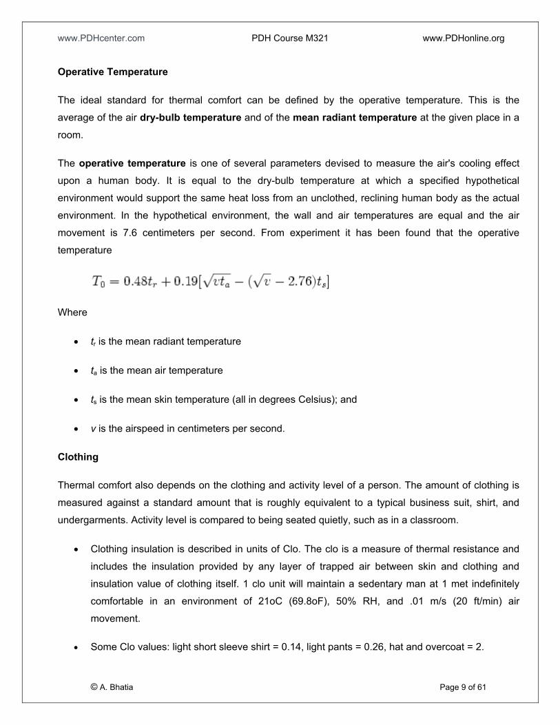
The operative temperature is one of several parameters devised to measure the air's cooling effect
upon a human body. It is equal to the dry-bulb temperature at which a specified hypothetical
environment would support the same heat loss from an unclothed, reclining human body as the actual
environment. In the hypothetical environment, the wall and air temperatures are equal and the air
movement is 7.6 centimeters per second. From experiment it has been found that the operative
temperature
Where
• tr is the mean radiant temperature
• ta is the mean air temperature
• ts is the mean skin temperature (all in degrees Celsius); and
• v is the airspeed in centimeters per second.
Clothing
Thermal comfort also depends on the clothing and activity level of a person. The amount of clothing is
measured against a standard amount that is roughly equivalent to a typical business suit, shirt, and
undergarments. Activity level is compared to being seated quietly, such as in a classroom.
• Clothing insulation is described in units of Clo. The clo is a measure of thermal resistance and
includes the insulation provided by any layer of trapped air between skin and clothing and
insulation value of clothing itself. 1 clo unit will maintain a sedentary man at 1 met indefinitely
comfortable in an environment of 21oC (69.8oF), 50% RH, and .01 m/s (20 ft/min) air
movement.
© A. Bhatia Page 9 of 61
• Some Clo values: light short sleeve shirt = 0.14, light pants = 0.26, hat and overcoat = 2.
www.PDHcenter.com PDH Course M321 www.PDHonline.org
• Adding 1 Clo of insulation permits a reduction of heat loss equivalent to that obtained by
decreasing air temperature by approximately 13° F.
• Clo units can be converted to R-value in SI units (K/ (W/m²) or RSI) by multiplying Clo by 0.155
(1 Clo = 0.155 RSI). (In imperial units 1 Clo corresponds to an R-value of 0.88 °F ft²hr/Btu.)
Thermal indices
Thermal sensations can be described as feelings of being hot, warm, neutral, cool, cold, and a range of
classification in between. There have been various attempts to find a single index that could be used to
determine thermal comfort conditions.
Wind Chill
Wind chill is the apparent temperature felt on exposed skin, which is a function of the air temperature
and wind speed. The wind chill temperature (often popularly called the wind chill factor) is always
lower than the air temperature, except at higher temperatures where wind chill is considered less
important. In cases where the apparent temperature is higher than the air temperature, the heat index
is used instead.
Heat Index
The heat index (HI) is an index that combines air temperature and relative humidity in an attempt to
determine the human-perceived equivalent temperature — how hot it feels, termed the felt air
temperature. The human body normally cools itself by perspiration, or sweating, which evaporates and
carries heat away from the body. However, when the relative humidity is high, the evaporation rate is
reduced, so heat is removed from the body at a lower rate causing it to retain more heat than it would in
dry air. Measurements have been taken based on subjective descriptions of how hot subjects feel for a
given temperature and humidity, allowing an index to be made which corresponds a temperature and
humidity combination to a higher temperature in dry air.
Effective temperature
© A. Bhatia Page 10 of 61
Effective temperature is an experimentally determined index of the various combinations of dry-bulb,
humidity, radiant conditions, and air movement that induce same thermal sensation. Effective
temperature of a given space may be defined as the dry-bulb temperature of an environment at 50%
RH and a specific uniform radiation condition; heat exchange of the environment is based on 0.6 clo,
www.PDHcenter.com PDH Course M321 www.PDHonline.org
still air (40 fpm or less), 1 hour exposure time, and sedentary activity level (about 1 met). It is a reliable
indicator of comfort with the thermal environment. Thus any space having an effective temperature of,
say, 75ºF will induce a sensation of warmth equivalent to 75ºF at 50% RH in almost still air and at a
metabolic rate of 1 met.
Comfort zone
As said, thermal comfort is a subjective consideration i.e. there is no magic condition which can be
measured as “comfortable”. Under identical conditions one individual may feel comfortable, the second
may not. Nevertheless, there is a range of conditions over which most people report that they are
comfortable. It is an area plotted on the psychrometric chart that pertains to those conditions of dry-bulb
temperature, wet-bulb temperature, wind speeds etc. in which most people wearing specified cloths
and involved in specific activity will feel comfortable, i.e., neither too cold nor too warm. The comfort
range of temperature varies between 70 to 76°F dry bulb temperatures and 45 - 65% relative humidity.
This applies mainly to summer air-conditioning. During cold winters the comfort condition would be in
the range of 65 to 68°F dry bulb temperature and relative humidity of a minimum of 30%.
PMV* Studies of personal comfort have shown that relative humidity ranges between 30% and 65%
can be considered 'comfortable' depending on activity. However, from the standpoint of indoor air
quality, upper ranges should be maintained below 50% (dust mite populations increase rapidly at
relative humidity levels above 50% and fungal amplification occurs above 65%). Below 30% respiratory
irritation occurs or static electric currents are a concern.
© A. Bhatia Page 11 of 61
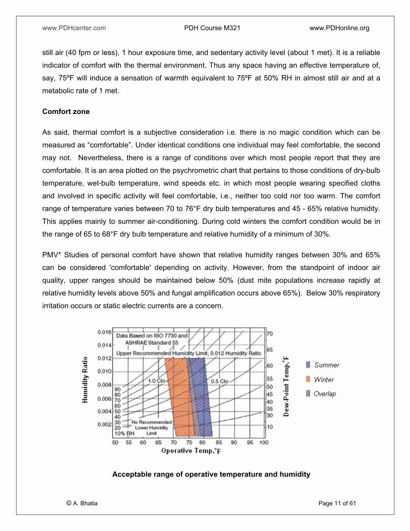
Acceptable range of operative temperature and humidity
www.PDHcenter.com PDH Course M321 www.PDHonline.org
Two comfort zones are defined by the shaded regions-one for winter and one for summer. The thermal
conditions within these envelopes are estimated to be acceptable to 80 percent of the occupants when
wearing clothing as indicated on the chart. To satisfy 90% of the people, the limits are reduced to one
third of the ranges. In the region where the zones overlap, people in summer dress tend to be slightly
cool, and those in winter clothing would feel a slightly warm sensation.
The upper and lower limits of humidity are based on respiratory health, mold growth, and other
moisture-related problems apart from physical comfort.
*PMV represents the 'predicted mean vote' (on the thermal sensation scale) of a large population of
people exposed to a certain environment. It predicts the subjective thermal sensation rating of a large
group based on 6 variables (4 environmental, 2 personal) that affect the human heat balance:
1. Activity . . . . . . . . . . . . . . . . . . . . . . . . . Personal
2. Clothing . . . . . . . . . . . . . . . . . . . . . . ... . Personal
3. Air Temperature . . . . . . . . . . . . . . . . . . . Environmental
4. Mean Radiant Temperature . . . . . . . . . . Environmental
5. Relative Air Velocity . . . . . . . . . . . . . . . . Environmental
6. Air Humidity . . . . . . . . . . . . . . . . . . . . . . Environmental
Quantitatively, PMV is measured on the ASHRAE thermal sensation scale (ASHRAE 1997), ranging
from (-3…….. 3) as follows:
-3 cold
-2 cool
-1 slightly cool
0 neutral
1 slightly warm
© A. Bhatia Page 12 of 61
2 warm
www.PDHcenter.com PDH Course M321 www.PDHonline.org
3 hot
Even though this scale is a nice characterization of thermal comfort, building occupants are different in
their tolerance levels and there is naturally a certain variance in the thermal sensations of a group.
Another term “PPD” predicted percent dissatisfied, predicts the expected fraction of a large group that
will align with a subjective assessment of hot or cold above an absolute PMV level of 1.5 scale units
(between slightly warm and slightly cool). It is basically an expression of ‘potential complainers’. As
PMV changes away from zero in either the positive or negative direction, PPD increases.
Learn more about “thermal comfort” --- refer
© A. Bhatia Page 13 of 61
http://dt.fme.vutbr.cz/enviro/Pohoda/thermal.htm
www.PDHcenter.com PDH Course M321 www.PDHonline.org
SECTION – 2 PSYCHROMETRICS
Definition
• Study of atmospheric conditions
• Deals with the thermodynamic properties of air-water vapor mixture
• Describes and analyzes the combined interactions of air, heat, and moisture.
Psychrometric chart
A psychrometric chart is a graphical presentation of the thermodynamic properties of moist air and
various air-conditioning processes and air-conditioning cycles. A psychrometric chart also helps in
calculating and analyzing the work and energy transfer of various air-conditioning processes and
cycles.
The most common chart used by practitioners and designers is the temperature - humidity ratio (w)
chart in which the dry bulb temperature (DBT) appears horizontally as the abscissa and the humidity
ratios (w) appear as the vertical axis.
© A. Bhatia Page 14 of 61
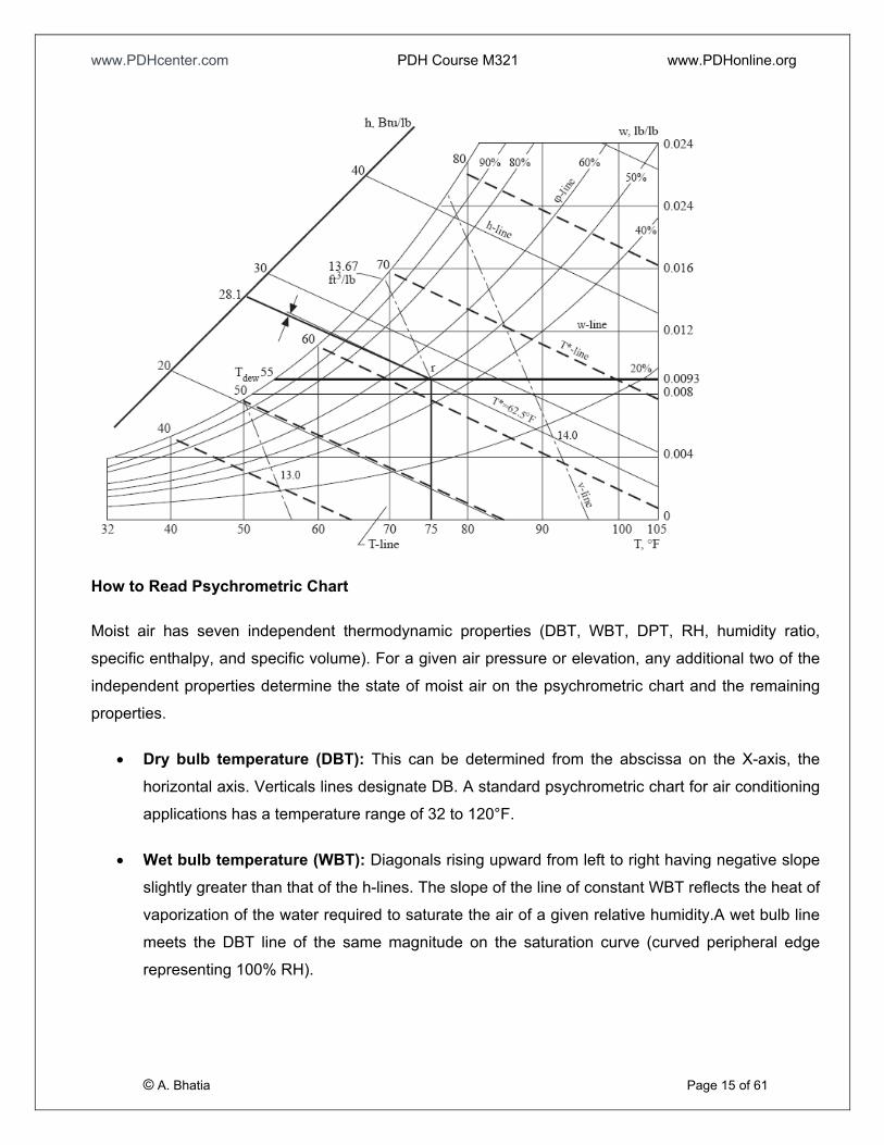
Abridged sample of psychrometric chart is shown below:
www.PDHcenter.com PDH Course M321 www.PDHonline.org
How to Read Psychrometric Chart
Moist air has seven independent thermodynamic properties (DBT, WBT, DPT, RH, humidity ratio,
specific enthalpy, and specific volume). For a given air pressure or elevation, any additional two of the
independent properties determine the state of moist air on the psychrometric chart and the remaining
properties.
• Dry bulb temperature (DBT): This can be determined from the abscissa on the X-axis, the
horizontal axis. Verticals lines designate DB. A standard psychrometric chart for air conditioning
applications has a temperature range of 32 to 120°F.
© A. Bhatia Page 15 of 61
• Wet bulb temperature (WBT): Diagonals rising upward from left to right having negative slope
slightly greater than that of the h-lines. The slope of the line of constant WBT reflects the heat of
vaporization of the water required to saturate the air of a given relative humidity.A wet bulb line
meets the DBT line of the same magnitude on the saturation curve (curved peripheral edge
representing 100% RH).
www.PDHcenter.com PDH Course M321 www.PDHonline.org
• Dew point temperature (DPT): Follow the horizontal line from the point where the line from the
horizontal axis arrives at 100% RH, also known as the saturation curve. Dew point is the
temperature at which a moist air sample at the same pressure would reach saturation. At this
saturation point, water vapor would begin to condense into liquid water fog or (if below freezing)
solid hoarfrost, as heat is removed.
• Relative humidity (RH - �: Curved lines that radiate from lower left to upper right are RH lines.
o Horizontal line at the bottom represents 0% RH; the uppermost curved line is 100% RH
line (also termed as saturation line).
o Intersection point of a water content line and the saturation line is known as the dew
point.
A saturation curve is a curve of the locus of state points of saturated moist air, that is, �= 100%.
On a saturation curve, dry bulb temperature (DBT), wet temperature bulb (WBT) and dew point
temperature (DPT) have the same value.
• Humidity ratio: Humidity ratio w-lines are horizontal lines. Marked on the Y-axis, they range
from 0 to 0.28 lb/lb. Also known as “moisture content”, “mixing ratio”, or “specific humidity”, it is
the proportion of mass of water vapor per unit mass of dry air at the given conditions (DBT,
WBT, DPT, RH, etc.). For a given DBT there will be a particular humidity ratio for which the air
sample is at 100% relative humidity. Humidity Ratio is dimensionless, but is sometimes
expressed as grams of water per kilogram of dry air or grains of water per pound of air.
• Specific enthalpy (h): Enthalpy lines incline downward to the right-hand side (negative slope)
at an angle of 23.5° to the horizontal line and have a range of 12 to 54 Btu/lb. Enthalpy
measures the heat content of air and is expressed in BTU per pound of air.
• Specific volume (v): Specific volume lines are represented by the diagonal lines close to 90º.
Specific volume lines have a far greater negative slope than h-lines and WBT lines. The moist
volume ranges from 12.5 - 15 ft3/lb. Specific volume, also called “inverse density”, is the volume
per unit mass of the air sample.
© A. Bhatia Page 16 of 61
The versatility of the psychrometric chart lies in the fact that by knowing two properties, the other
properties can be determined. Thermodynamic properties of moist air are affected by atmospheric
pressure. The standard atmospheric pressure is 29.92in-Hg (14.697 psi) at sea level. ASHRAE also
www.PDHcenter.com PDH Course M321 www.PDHonline.org
published charts for high altitudes of 5000 ft, 24.89 in- Hg, and 7500 ft, 22.65in- Hg. Both of them are in
the normal temperature range.
Example
An air-conditioned room at sea level has an indoor design temperature of 75°F and a relative humidity
of 50%. Determine the humidity ratio, enthalpy, density, dew point, and thermodynamic wet bulb
temperature of the indoor air at design condition.
Solution
Find the room temperature 75°F on the horizontal temperature scale.
• Draw a line parallel to the 75°F temperature line and establish the point where it meets the
relative humidity curve of 50% at point (r). This point denotes the state point of room air.
• Draw a horizontal line toward the humidity ratio scale from point (r). This line meets the ordinate
and thus determines the room air humidity ratio w = 0.0093 lb/lb.
• Draw a line from point (r) parallel to the enthalpy line. This line determines the enthalpy of room
air on the enthalpy scale, h = 28.1 Btu/lb.
• Draw a line through point (r) parallel to the moist volume line. The perpendicular scale of this
line indicates v = 13.67 ft3/lb.
• Draw a horizontal line to the left from point (r). This line meets the saturation curve and
determines the dew point temperature, Tdew = 55°F.
• Draw a line through point (r) parallel to the wet bulb line. The perpendicular scale to this line
indicates that the thermodynamic wet bulb temperature (WBT) = 62.5°F.
Psychrometrics Concept using Ideal Gas Law
Ideal gas law describes the relationship of thermodynamic properties of real gas, and is given by
equation:
pv = n RT
© A. Bhatia Page 17 of 61
Or
www.PDHcenter.com PDH Course M321 www.PDHonline.org
pV = n RT
Where
• p is the absolute pressure of the gas, psf (1 psf = 144 psi)
• v is the specific volume of the gas, ft3/lb
• V is the Volume of the gas, ft3
• n is the number of moles of gas [for air n = 28.9645 lbm / (lb-mol)]
• R is the universal gas constant [for air R is found by dividing the universal gas constant by the
molecular weight i.e. 1545.32 / 28.9645 = 53.352 ft - lb / lbm-R]
• T is the absolute temperature, R
By manipulating the ideal gas equation, a relationship between the ideal gas law and the density for air
can be developed. As the amount of substance could be given in mass instead of moles, sometimes an
alternative form of the ideal gas law is useful. The number of moles (n) is equal to the mass (m) divided
by the molar mass (M):
n = m / M
By replacing, we get
From where
This form of the ideal gas law is particularly useful because it links pressure, density and temperature
in a unique formula independent from the quantity of the considered gas. Looking at the new equation
one can see that the density is inversely proportional to the gas constant R.
© A. Bhatia Page 18 of 61
Air is not 100% dry and contains moisture. The amount of water vapor contained in the moist air within
the temperature range 0 to 100°F changes from 0.05 to 3% by mass. The variation of water vapor has
www.PDHcenter.com PDH Course M321 www.PDHonline.org
a critical influence on the characteristics of moist air and can have a dramatic effect on our perception
of comfort.
For engineering purposes, moist air can be considered as a mixture of perfect gases and obeys the
ideal gas law. Thus,
• Dry air : pa V = na RT
• Water vapor pw V = nw RT
Where
pa and pw are the partial pressures of dry air and water vapor, respectively. The terms na and nw
correspond to the number of moles of these components in the mixture.
These two equations may be combined.
Dalton’s Law
Dalton’s Law states that the total pressure exerted by a mixture of perfect gases is the same as that
exerted by the constituent gases independently. The sum of the partial pressures above, therefore, is
the total pressure exerted by the moist air.
pat = pa + pw
Where
• pat = atmospheric pressure of the moist air, psia
• pa = = partial pressure of dry air, psia
• pw = partial pressure of water vapor, psia
© A. Bhatia Page 19 of 61
Dalton’s law is summarized from the experimental results and is more accurate at low gas pressure. A
consequence to Dalton’s law of Partial Pressure is that it can be extended to describe the relationship
of internal energy, enthalpy, and entropy of the gaseous constituents in a mixture, for example, the total
enthalpy of a mixture of gases will equal the sum of the enthalpies of each component part, i.e.:
www.PDHcenter.com PDH Course M321 www.PDHonline.org
h = m1 .h1 + m2. h2 + m3 .h3 +.... etc
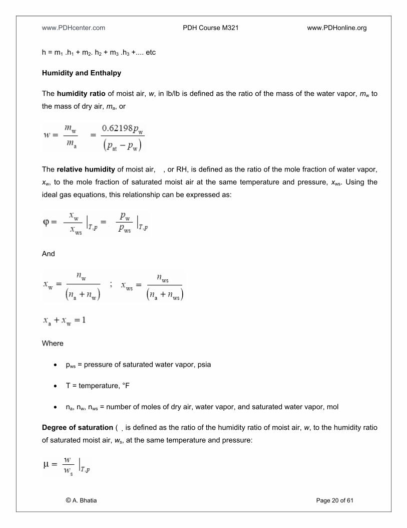
Humidity and Enthalpy
The humidity ratio of moist air, w, in lb/lb is defined as the ratio of the mass of the water vapor, mw to
the mass of dry air, ma, or
The relative humidity of moist air, �, or RH, is defined as the ratio of the mole fraction of water vapor,
xw, to the mole fraction of saturated moist air at the same temperature and pressure, xws. Using the
ideal gas equations, this relationship can be expressed as:
And
Where
• pws = pressure of saturated water vapor, psia
• T = temperature, °F
• na, nw, nws = number of moles of dry air, water vapor, and saturated water vapor, mol
Degree of saturation (� is defined as the ratio of the humidity ratio of moist air, w, to the humidity ratio
of saturated moist air, ws, at the same temperature and pressure:
© A. Bhatia Page 20 of 61
www.PDHcenter.com PDH Course M321 www.PDHonline.org
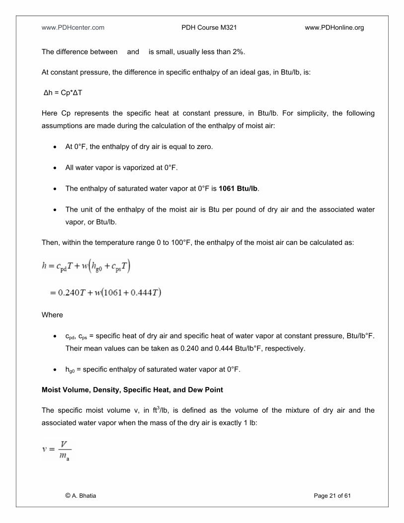
The difference between � and � is small, usually less than 2%.
At constant pressure, the difference in specific enthalpy of an ideal gas, in Btu/lb, is:
Δh = Cp*ΔT
Here Cp represents the specific heat at constant pressure, in Btu/lb. For simplicity, the following
assumptions are made during the calculation of the enthalpy of moist air:
• At 0°F, the enthalpy of dry air is equal to zero.
• All water vapor is vaporized at 0°F.
• The enthalpy of saturated water vapor at 0°F is 1061 Btu/lb.
• The unit of the enthalpy of the moist air is Btu per pound of dry air and the associated water
vapor, or Btu/lb.
Then, within the temperature range 0 to 100°F, the enthalpy of the moist air can be calculated as:
Where
• cpd, cps = specific heat of dry air and specific heat of water vapor at constant pressure, Btu/lb°F.
Their mean values can be taken as 0.240 and 0.444 Btu/lb°F, respectively.
• hg0 = specific enthalpy of saturated water vapor at 0°F.
Moist Volume, Density, Specific Heat, and Dew Point
The specific moist volume v, in ft3/lb, is defined as the volume of the mixture of dry air and the
associated water vapor when the mass of the dry air is exactly 1 lb:
© A. Bhatia Page 21 of 61
www.PDHcenter.com PDH Course M321 www.PDHonline.org
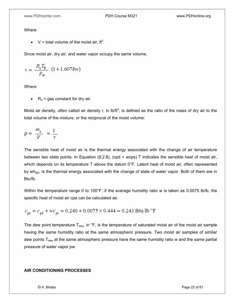
Where
• V = total volume of the moist air, ft3.
Since moist air, dry air, and water vapor occupy the same volume,
Where
• Ra = gas constant for dry air.
Moist air density, often called air density r, in lb/ft3, is defined as the ratio of the mass of dry air to the
total volume of the mixture, or the reciprocal of the moist volume:
The sensible heat of moist air is the thermal energy associated with the change of air temperature
between two state points. In Equation (9.2.8), (cpd + wcps) T indicates the sensible heat of moist air,
which depends on its temperature T above the datum 0°F. Latent heat of moist air, often represented
by whfg0, is the thermal energy associated with the change of state of water vapor. Both of them are in
Btu/lb.
Within the temperature range 0 to 100°F, if the average humidity ratio w is taken as 0.0075 lb/lb, the
specific heat of moist air cpa can be calculated as:
The dew point temperature Tdew, in °F, is the temperature of saturated moist air of the moist air sample
having the same humidity ratio at the same atmospheric pressure. Two moist air samples of similar
dew points Tdew at the same atmospheric pressure have the same humidity ratio w and the same partial
pressure of water vapor pw
© A. Bhatia Page 22 of 61
AIR CONDITIONING PROCESSES
www.PDHcenter.com PDH Course M321 www.PDHonline.org
Psychrometrics is widely used to illustrate and analyze the change in properties and the thermal
characteristics of the air-conditioning process and cycles. An air-conditioning process describes the
change in thermodynamic properties of moist air between the initial and final stages of conditioning as
well as the corresponding energy and mass transfers between the moist air and a medium, such as
water, refrigerant, absorbent or adsorbent, or moist air itself. The energy balance and conservation of
mass are the two principles used for the analysis and the calculation of the thermodynamic properties
of the moist air.
Four basic processes for summer and winter air conditioning systems are 1) Mixing, 2) Sensible
Cooling and Heating, 3) Cooling with Dehumidification and 4) Humidification
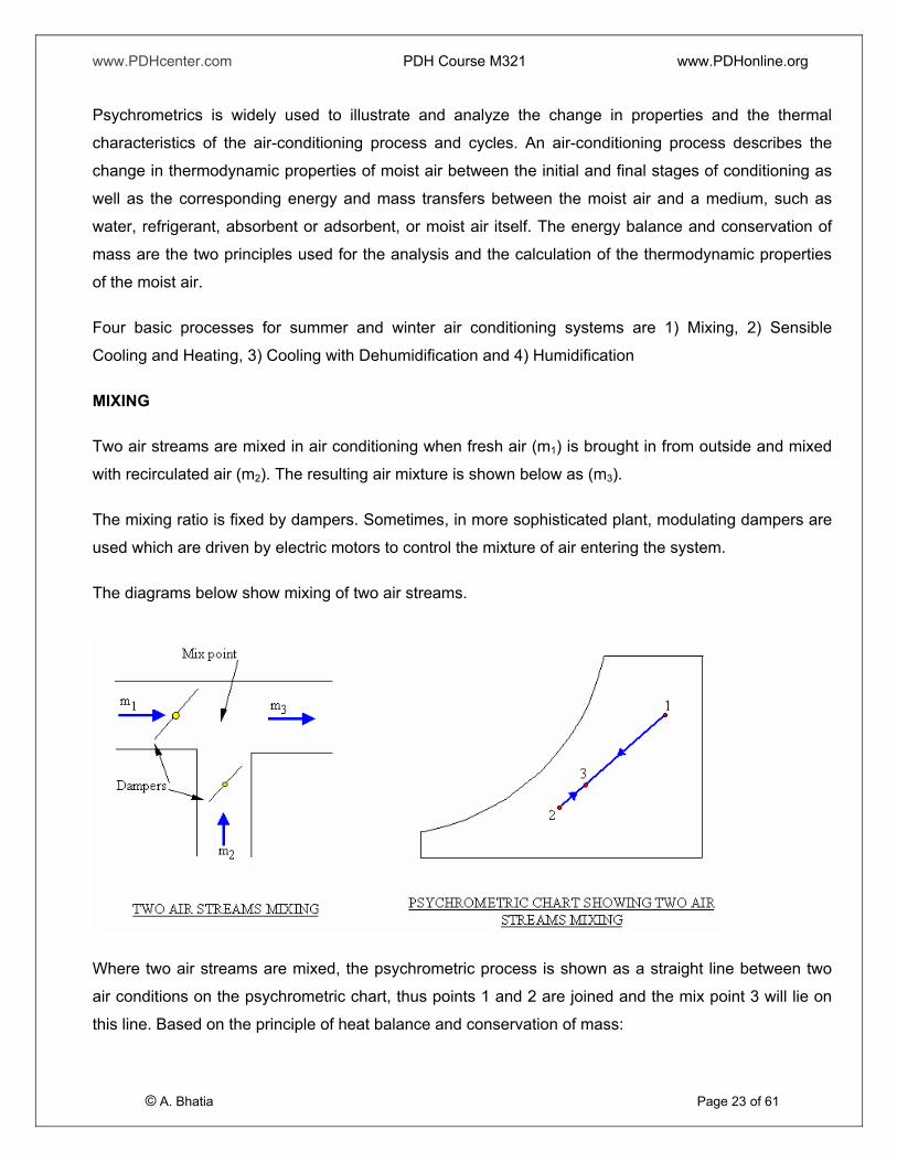
MIXING
Two air streams are mixed in air conditioning when fresh air (m1) is brought in from outside and mixed
with recirculated air (m2). The resulting air mixture is shown below as (m3).
The mixing ratio is fixed by dampers. Sometimes, in more sophisticated plant, modulating dampers are
used which are driven by electric motors to control the mixture of air entering the system.
The diagrams below show mixing of two air streams.
© A. Bhatia Page 23 of 61
Where two air streams are mixed, the psychrometric process is shown as a straight line between two
air conditions on the psychrometric chart, thus points 1 and 2 are joined and the mix point 3 will lie on
this line. Based on the principle of heat balance and conservation of mass:
www.PDHcenter.com PDH Course M321 www.PDHonline.org
m1 + m2 = m3
m1 h1 + m2 h2 = m3 h3
m1 w1 + m2 w2 = m3 w3
m1 T1 + m2 T2 = m3 T3
In Equations above, m, represents the mass flow rate of air, lb/min; h the enthalpy, in Btu/lb; w the
humidity ratio, in lb/lb; and T the temperature, in °F. Subscripts 1 and 2 indicate air streams 1 and 2 and
3 the mixture; also,
Similarly
Mixing point 3 must lie on the line that joins points 1 and 2.
SENSIBLE COOLING AND HEATING
© A. Bhatia Page 24 of 61
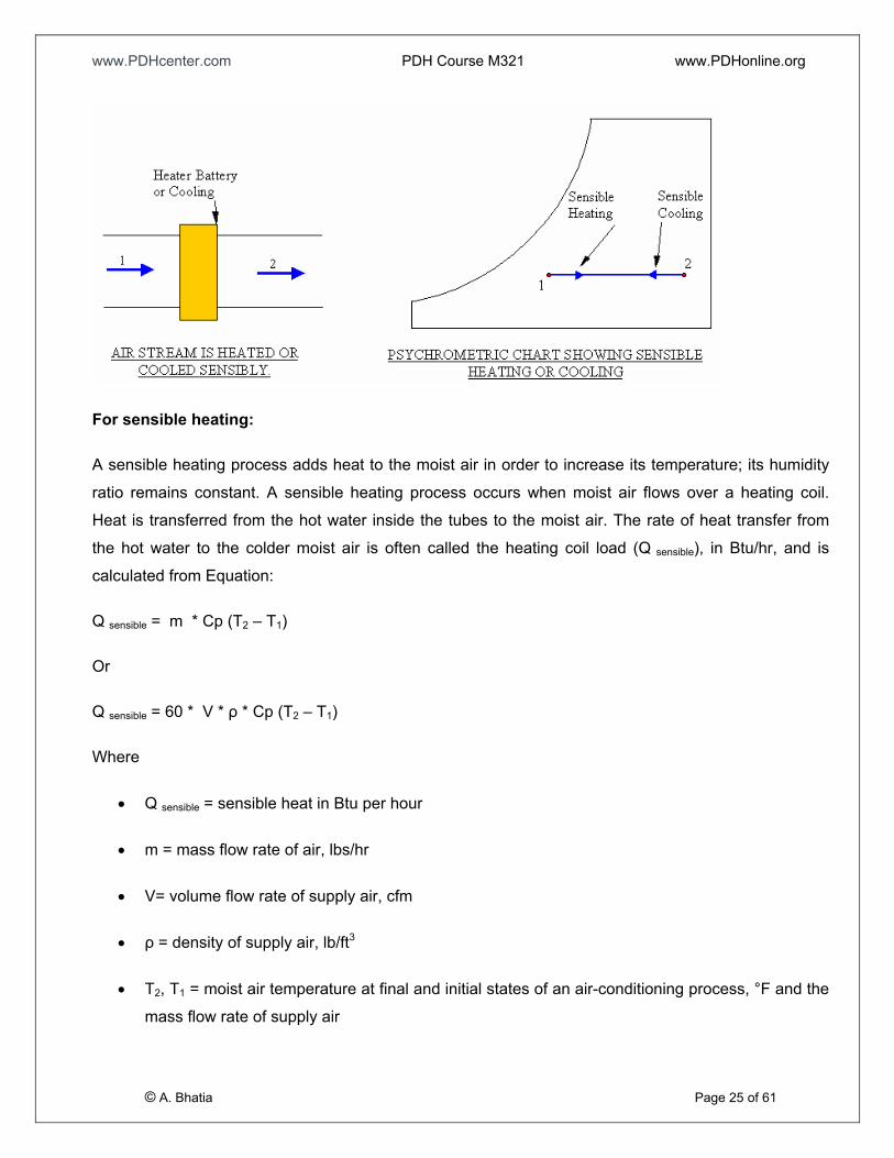
When air is heated or cooled sensibly, that is, when no moisture is added or removed, this process is
represented by a horizontal line on a psychrometric chart.
www.PDHcenter.com PDH Course M321 www.PDHonline.org
For sensible heating:
A sensible heating process adds heat to the moist air in order to increase its temperature; its humidity
ratio remains constant. A sensible heating process occurs when moist air flows over a heating coil.
Heat is transferred from the hot water inside the tubes to the moist air. The rate of heat transfer from
the hot water to the colder moist air is often called the heating coil load (Q sensible), in Btu/hr, and is
calculated from Equation:
Q sensible = m * Cp (T2 – T1)
Or
Q sensible = 60 * V * ρ * Cp (T2 – T1)
Where
• Q sensible = sensible heat in Btu per hour
• m = mass flow rate of air, lbs/hr
• V= volume flow rate of supply air, cfm
• ρ = density of supply air, lb/ft3
© A. Bhatia Page 25 of 61
• T2, T1 = moist air temperature at final and initial states of an air-conditioning process, °F and the
mass flow rate of supply air
www.PDHcenter.com PDH Course M321 www.PDHonline.org
Or more accurately from psychrometric chart:
Q sensible = m x (h2 - h1)
Where
• h2, h1 = moist air enthalpy at final and initial states of an air-conditioning process, Btu/lb
For sensible cooling:
A sensible cooling process removes heat from the moist air, resulting in a drop of its temperature; The
sensible cooling process occurs when moist air flows through a cooling coil containing chilled water at a
temperature equal to or greater than the dew point of the entering moist air. The sensible cooling load
can also be calculated similar way as sensible heating equation.
COOLING AND DEHUMIDIFICATION
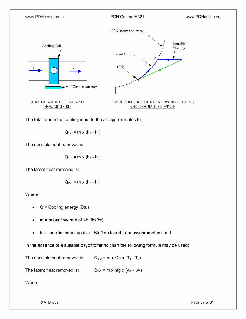
In a cooling and dehumidifying process, both the humidity ratio and temperature of moist air decrease.
Some water vapor is condensed in the form of liquid water, called a condensate.
The most commonly used method of removing water vapor from air (dehumidification) is to cool the air
below its dew point. The dew point of air is when it is fully saturated i.e. at 100% saturation. When air
is fully saturated it cannot hold any more moisture in the form of water vapor. If the air is cooled to the
dew point air and is still further cooled then moisture will drop out of the air in the form of condensate.
This can be shown on a psychrometric chart as air sensibly cooled until it becomes fully saturated (the
dew point is reached) and then the air is cooled latently to a lower temperature.
This is apparent on the psychrometric chart as a horizontal line for sensible cooling to the 100%
saturation curve and then the process follows the 100% saturation curve down to another point at a
lower temperature. This lower temperature is sometimes called the Apparatus dew Point (ADP) of the
cooling coil. In reality the ADP of the cooling coil is close to the cooling liquid temperature inside the
coil.
Chilled water or refrigerant may be the cooling liquid.
© A. Bhatia Page 26 of 61
The psychrometric process from state point 1 to 2 to 3 may be shown as a straight line for simplicity.
www.PDHcenter.com PDH Course M321 www.PDHonline.org
The total amount of cooling input to the air approximates to;
Q1-3 = m x (h1 - h3)
The sensible heat removed is:
Q1-2 = m x (h1 - h2)
The latent heat removed is:
Q2-3 = m x (h2 - h3)
Where:
• Q = Cooling energy (Btu)
• m = mass flow rate of air (lbs/hr)
• h = specific enthalpy of air (Btu/lbs) found from psychrometric chart.
In the absence of a suitable psychrometric chart the following formula may be used;
The sensible heat removed is: Q1-2 = m x Cp x (T1 - T2)
The latent heat removed is: Q2-3 = m x hfg x (w2 - w3)
© A. Bhatia Page 27 of 61
Where:
www.PDHcenter.com PDH Course M321 www.PDHonline.org
• Q = Cooling energy (Btu/hr)
• m = mass flow rate of air (lbs/hr)
• Cp = Specific heat capacity of air, may be taken as 1.01 Btu/lb- degF
• T = Dry bulb temperature of air (oF)
• hfg = latent heat of vaporization of water, may be taken as 1060 Btu/lb
• w = moisture content of air from psychrometric chart (lb/lb-dry air)
Sensible Heat Factor or Ratio (SHR)
The sensible heat ratio (SHR) of an air-conditioning process is defined as the ratio of the change in
absolute value of sensible heat to the change in absolute value of total heat, both in Btu/hr:
SHR is a useful indication of dehumidification requirements. Lower SHR value indicates that the
dehumidification requirement will be high and the supply airflow rate will be less (refer end of this
section for explanation).
The key indicators are:
o SHR from 0.95 - 1.00 for Precision air conditioning (computers and data canters)
o SHR from 0.65 - 0.75 for Comfort cooling (office applications, people)
o SHR from 0.50 - 0.60 for Dehumidification (pools and outside air)
HUMIDIFICATION
© A. Bhatia Page 28 of 61
In a humidifying process, water vapor is added to moist air and increases the humidity ratio of the moist
air entering the humidifier if the moist air is not saturated. Large-scale humidification of moist air is
usually performed by steam injection, evaporation from a water spray, atomizing water, a wetted
medium, or submerged heating elements.
www.PDHcenter.com PDH Course M321 www.PDHonline.org
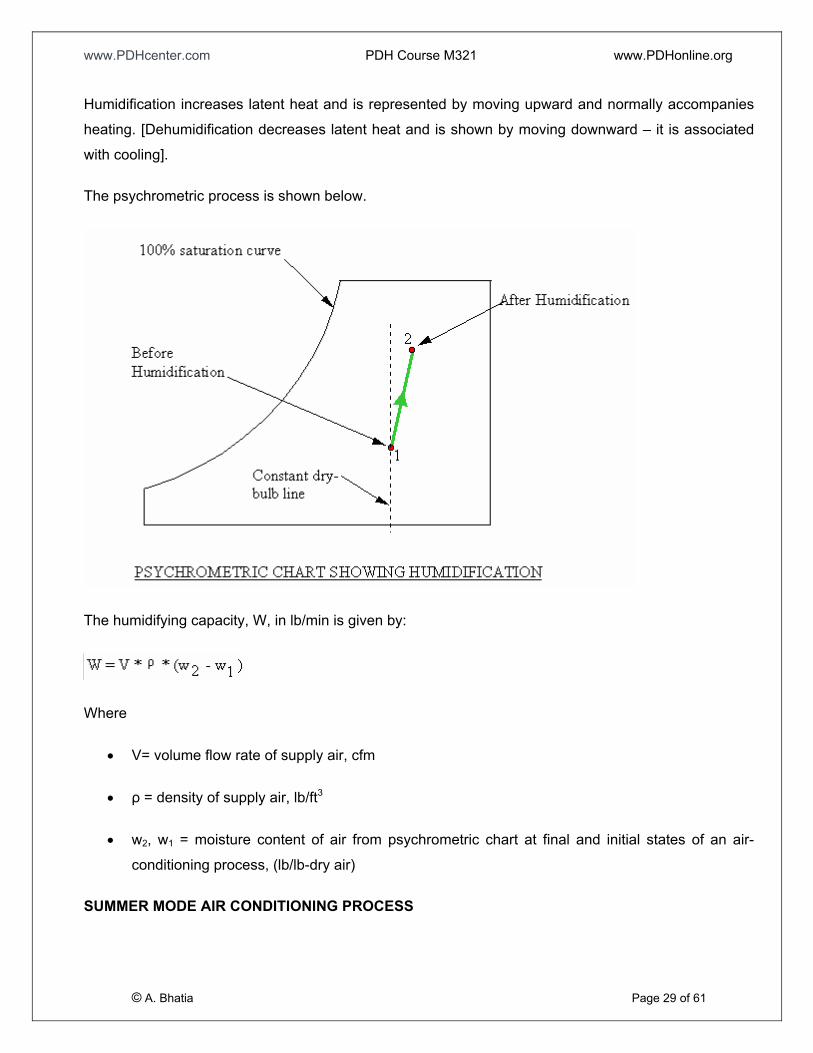
Humidification increases latent heat and is represented by moving upward and normally accompanies
heating. [Dehumidification decreases latent heat and is shown by moving downward – it is associated
with cooling].
The psychrometric process is shown below.
The humidifying capacity, W, in lb/min is given by:
Where
• V= volume flow rate of supply air, cfm
• ρ = density of supply air, lb/ft3
• w2, w1 = moisture content of air from psychrometric chart at final and initial states of an air-
conditioning process, (lb/lb-dry air)
© A. Bhatia Page 29 of 61
SUMMER MODE AIR CONDITIONING PROCESS
www.PDHcenter.com PDH Course M321 www.PDHonline.org
An air-conditioning cycle comprises several air-conditioning processes that are connected in a
sequential order. An air-conditioning cycle determines the operating performance of the air system in
an air conditioning system. The working substance to condition air may be chilled or hot water,
refrigerant, desiccant, etc.
Each type of air system has its own air-conditioning cycle. Psychrometric analysis of an air-conditioning
cycle is an important tool in determining its operating characteristics and the state of moist air at various
system components, including the volume flow rate of supply air, the coil’s load, and the humidifying
and dehumidifying capacity.
According to the cycle performance, air-conditioning cycles can be grouped into two categories:
• Open cycle, in which the moist air at its end state does not resume its original state. An air
conditioning cycle with all outdoor air is an open cycle.
• Closed cycle, in which moist air resumes its original state at its end state. Air-conditioning cycle
that conditions the mixture of recirculating and outdoor air, supplies it; recirculates part of the
return air, and mixes it again with outdoor air is a closed cycle.
A basic air-conditioning system is a packaged system of supply air at a constant volume flow rate,
serving a single zone, equipped with only a single supply/return duct. A single zone is a conditioned
space for which a single controller is used to maintain a unique indoor operating parameter, probably
indoor temperature.
© A. Bhatia Page 30 of 61
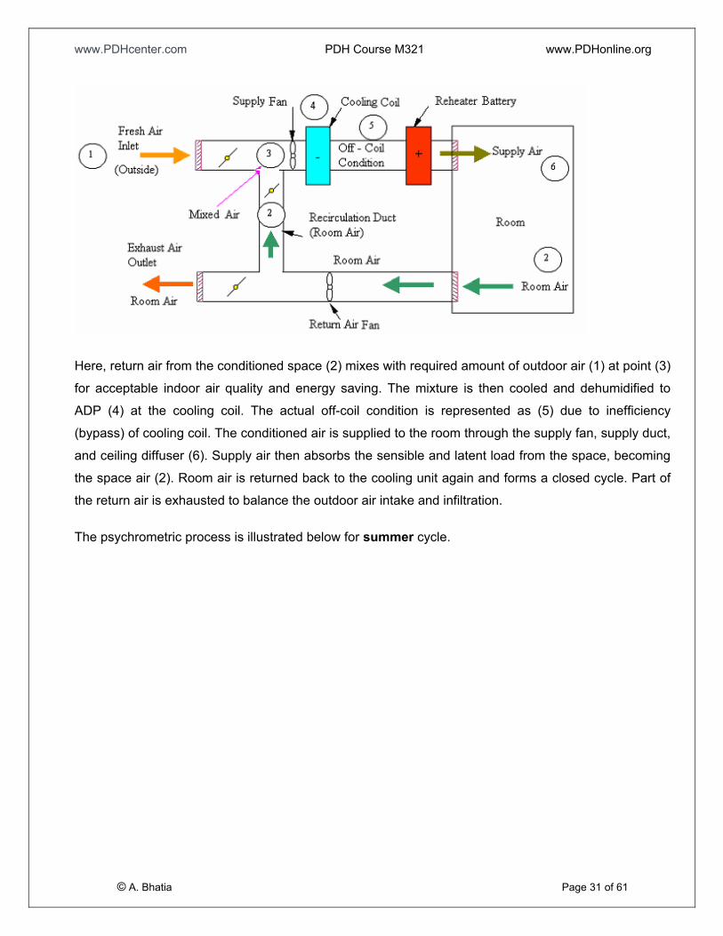
A basic air-conditioning schematic for summer mode is shown below:
www.PDHcenter.com PDH Course M321 www.PDHonline.org
Here, return air from the conditioned space (2) mixes with required amount of outdoor air (1) at point (3)
for acceptable indoor air quality and energy saving. The mixture is then cooled and dehumidified to
ADP (4) at the cooling coil. The actual off-coil condition is represented as (5) due to inefficiency
(bypass) of cooling coil. The conditioned air is supplied to the room through the supply fan, supply duct,
and ceiling diffuser (6). Supply air then absorbs the sensible and latent load from the space, becoming
the space air (2). Room air is returned back to the cooling unit again and forms a closed cycle. Part of
the return air is exhausted to balance the outdoor air intake and infiltration.
© A. Bhatia Page 31 of 61
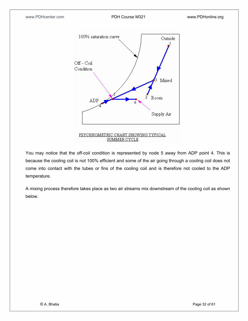
The psychrometric process is illustrated below for summer cycle.
www.PDHcenter.com PDH Course M321 www.PDHonline.org
You may notice that the off-coil condition is represented by node 5 away from ADP point 4. This is
because the cooling coil is not 100% efficient and some of the air going through a cooling coil does not
come into contact with the tubes or fins of the cooling coil and is therefore not cooled to the ADP
temperature.
© A. Bhatia Page 32 of 61
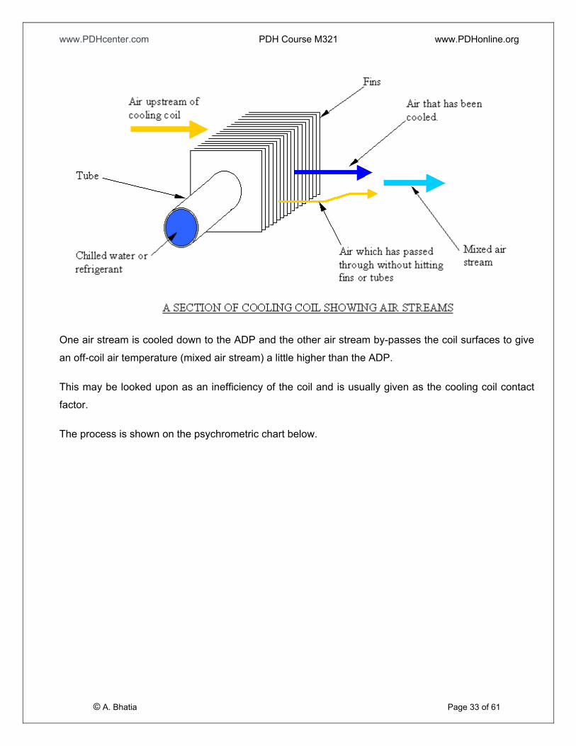
A mixing process therefore takes place as two air streams mix downstream of the cooling coil as shown
below.
www.PDHcenter.com PDH Course M321 www.PDHonline.org
One air stream is cooled down to the ADP and the other air stream by-passes the coil surfaces to give
an off-coil air temperature (mixed air stream) a little higher than the ADP.
This may be looked upon as an inefficiency of the coil and is usually given as the cooling coil contact
factor.
© A. Bhatia Page 33 of 61
The process is shown on the psychrometric chart below.
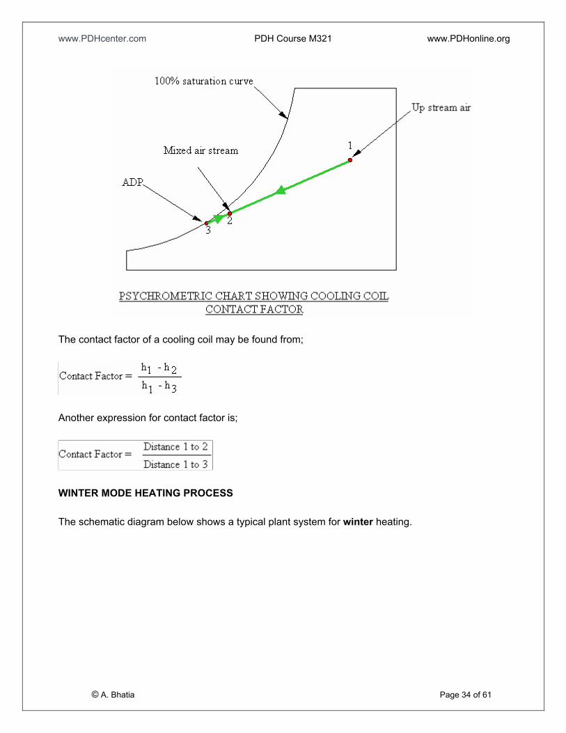
www.PDHcenter.com PDH Course M321 www.PDHonline.org
The contact factor of a cooling coil may be found from;
Another expression for contact factor is;
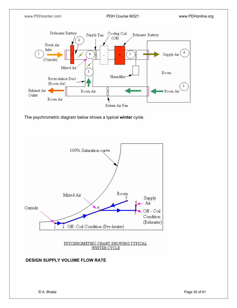
WINTER MODE HEATING PROCESS
© A. Bhatia Page 34 of 61
The schematic diagram below shows a typical plant system for winter heating.
www.PDHcenter.com PDH Course M321 www.PDHonline.org
The psychrometric diagram below shows a typical winter cycle.
© A. Bhatia Page 35 of 61
DESIGN SUPPLY VOLUME FLOW RATE
www.PDHcenter.com PDH Course M321 www.PDHonline.org
Design supply volume flow rate is estimated to determine the size of fans, grills, outlets, air-handling
units, and packaged units.
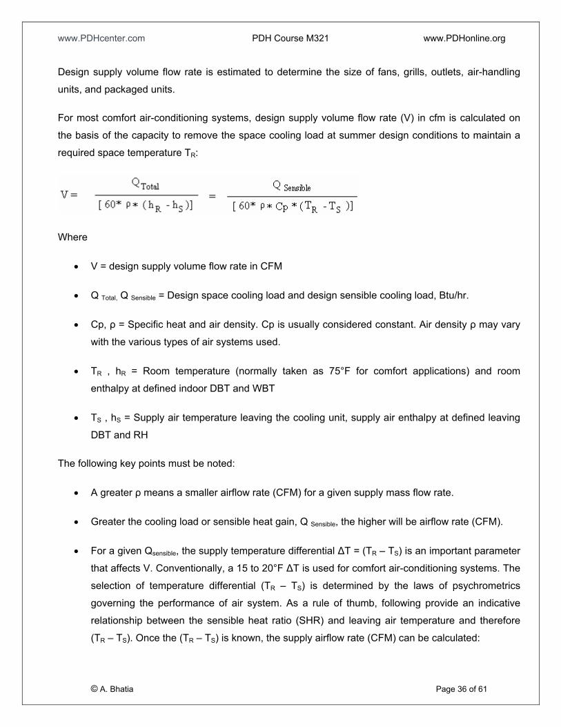
For most comfort air-conditioning systems, design supply volume flow rate (V) in cfm is calculated on
the basis of the capacity to remove the space cooling load at summer design conditions to maintain a
required space temperature TR:
Where
• V = design supply volume flow rate in CFM
• Q Total, Q Sensible = Design space cooling load and design sensible cooling load, Btu/hr.
• Cp, ρ = Specific heat and air density. Cp is usually considered constant. Air density ρ may vary
with the various types of air systems used.
• TR , hR = Room temperature (normally taken as 75°F for comfort applications) and room
enthalpy at defined indoor DBT and WBT
• TS , hS = Supply air temperature leaving the cooling unit, supply air enthalpy at defined leaving
DBT and RH
The following key points must be noted:
• A greater ρ means a smaller airflow rate (CFM) for a given supply mass flow rate.
• Greater the cooling load or sensible heat gain, Q Sensible, the higher will be airflow rate (CFM).
© A. Bhatia Page 36 of 61
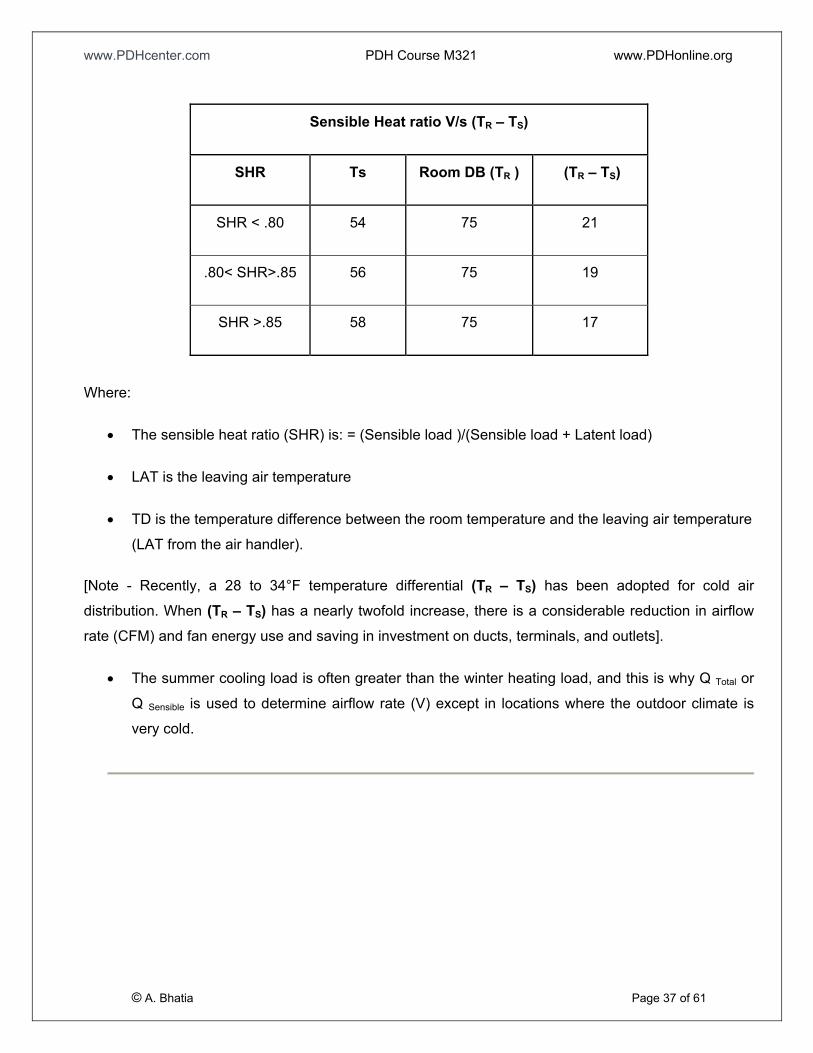
• For a given Qsensible, the supply temperature differential ΔT = (TR – TS) is an important parameter
that affects V. Conventionally, a 15 to 20°F ΔT is used for comfort air-conditioning systems. The
selection of temperature differential (TR – TS) is determined by the laws of psychrometrics
governing the performance of air system. As a rule of thumb, following provide an indicative
relationship between the sensible heat ratio (SHR) and leaving air temperature and therefore
(TR – TS). Once the (TR – TS) is known, the supply airflow rate (CFM) can be calculated:
www.PDHcenter.com PDH Course M321 www.PDHonline.org
Where:
• The sensible heat ratio (SHR) is: = (Sensible load )/(Sensible load + Latent load)
• LAT is the leaving air temperature
• TD is the temperature difference between the room temperature and the leaving air temperature
(LAT from the air handler).
[Note - Recently, a 28 to 34°F temperature differential (TR – TS) has been adopted for cold air
distribution. When (TR – TS) has a nearly twofold increase, there is a considerable reduction in airflow
rate (CFM) and fan energy use and saving in investment on ducts, terminals, and outlets].
• The summer cooling load is often greater than the winter heating load, and this is why Q Total or
Q Sensible is used to determine airflow rate (V) except in locations where the outdoor climate is
very cold.
© A. Bhatia Page 37 of 61
Sensible Heat ratio V/s (TR – TS)
SHR Ts Room DB (TR ) (TR – TS)
SHR < .80 54 75 21
.80< SHR>.85 56 75 19
SHR >.85 58 75 17
www.PDHcenter.com PDH Course M321 www.PDHonline.org
SECTION – 3 MODES OF HEAT TRANSFER
All the materials that are used in the construction absorb and transfer heat. By knowing the resistance
of heat flow through a building component (R-value), you can calculate the total amount of heat
entering the building. The basic equation to determine the heat loss or gain by conduction is known as
Fourier’s Law and is expressed as:
Q = k x A x ΔT / t
Where
• Q = Hat transferred per unit time (Btu/hr)
• A = Heat transfer area (ft2)
• k = Thermal conductivity of the material (Btu/ (hr °F ft2/ft))
• ΔT = Temperature difference across the material (°F)
• t = material thickness (ft)
For example, the heat transfer in 24 hours through 2 sq-ft. of material, 3" thick, having a thermal
conductivity factor of 0.25, with an average temperature difference across the material of 70°F would be
calculated as follows:
Before we go further, let’s refresh few basic heat transfer fundamentals.
Modes of heat transfer
• Mainly involves conduction, convection, and radiation.
• Evaporation is less important when there is no moisture involved.
© A. Bhatia Page 38 of 61
For HVAC load calculation purposes, conduction and radiation are primarily considered. Conduction is
the transfer of heat through an object and radiation is the transfer of heat through electromagnetic
waves, in this case sunlight. Heat travels from hot to cold and construction materials resist the flow of
heat through them differently. For example, heat passes through glass much easier than wood siding.
www.PDHcenter.com PDH Course M321 www.PDHonline.org
Heat flow through solids - Terminology
• Conductivity: Designated by k. Represents BTUH that flows through 1 sq-ft of material, 1 in.
thick, when temperature drop through this material is 1oF. Thermal conductivity is expressed in
(Btu-in/hr ft2 °F). Materials with lower k-values are better insulators. Insulation materials usually
have k-factors less than one and are reported at what is called mean temperature. To determine
the mean temperature, measure the surface temperatures on both sides of the insulation, add
them together and divide by two. “As mean temperatures rises, so does the k-factor”
• Conductance: Designated by C. Represents BTUH that flows through 1 sq-ft of material of a
given or specified thickness when temperature drop through this material is 1oF. C factor is
similar to ‘k’, except it is the rate of heat flow through an actual thickness of material, where ‘k’ is
a factor per inch. The C-factor is the k-factor divided by the thickness of the insulation. The
lower the C value, the better the insulator.
• Resistivity: It is an index of the tendency of a material to resist heat flow per inch of its
thickness. Reciprocal of k. Designated by r. Thermal Resistivity is expressed in (hr-°F ft2)/ (Btu
in).
• Resistance: It is an index of the tendency of a material of given thickness to resist heat flow.
Reciprocal of C. Designated by R. Note the relationship between resistance, conductance,
resistivity and thermal conductivity below:
R = 1/C = rx = x/k, where x = thickness
The higher the R-value, the higher (better) the insulating value.
R Values change as the thickness of the insulating material changes.
R-value for material only deals with conductive heat transfer. Since the total heat transferred by
conduction varies directly with time, area, and temperature difference, and varies inversely with
the thickness of the material, it is readily apparent that in order to reduce heat transfer, the ‘k’
factor should be as small as possible, and the material as thick as possible.
© A. Bhatia Page 39 of 61
• U-value: Overall coefficient of heat transmission of an assembly of materials. This a single,
composite heat transfer coefficient that is used to correlate the overall rate of heat transfer with
surface area and temperature difference. R-value and U-factor are the inverse of one another: U
www.PDHcenter.com PDH Course M321 www.PDHonline.org
= 1/R. For example, a wall with a U-value of 0.25 would have a resistance value of R = I/U =
1/0.25= 4.0. Materials that are very good at resisting the flow of heat (high R-value, low U-
factor) can serve as insulation materials. The Overall Coefficient of Heat Transmission is
expressed in Btu/ (hr 0F ft2).
Example
Calculate the U factor of a wall composed of 2" of material having a ‘k’ factor of 0.80, and 2" of
insulation having a conductance of 0.16.
U value is found as follows:
R total = 1/C + X1/k1 or
R total = 1/0.16 + 2/0.80
R total = 8.75
U = 1/R or 1/8.75 = 0.114 Btu/hr ft2 °F
Once the U factor is known, the heat gain by transmission through a given wall can be calculated by the
basic heat transfer equation. Assuming an area of 100 square feet wall with an inside temperature of
85°F and an outside temperature of 115°F, the heat transmission would be:
Q = U x A x TD
Q = 0.114 x 100 x 30
Q = 342 Btu/hr
Series heat flow
© A. Bhatia Page 40 of 61
Building envelope is typically composed of various elements. A wall may be constructed of hardboard
(facing outdoors), plywood (facing indoors) and sandwich insulation in between. When a building
structure is composed of various layers of construction elements having resistances R1, R2, R3…. Rn,
the overall resistance value is sum of all individual resistances for whole wall, internal air spaces,
insulation materials and air films adjacent to solid materials. Individual R-values are used in calculating
overall heat transfer coefficients.
www.PDHcenter.com PDH Course M321 www.PDHonline.org
For layered construction, with paths of heat flow in series, the total thermal resistance of the wall is
obtained by:
R Total =R1+R2+...
Or R Total = 1/C + x1/k1 + x2 /k2…
Where
• C is the conductance
• x1 is the thickness of material one
• x2 is the thickness of material two
• k1 is the thermal conductivity of material one
• k2 is the thermal conductivity of material two
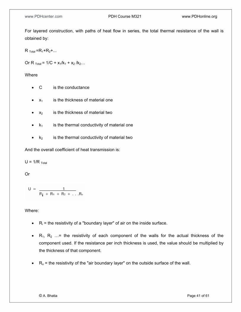
And the overall coefficient of heat transmission is:
U = 1/R Total
Or
Where:
• Ri = the resistivity of a "boundary layer" of air on the inside surface.
• R1, R2 …= the resistivity of each component of the walls for the actual thickness of the
component used. If the resistance per inch thickness is used, the value should be multiplied by
the thickness of that component.
© A. Bhatia Page 41 of 61
• Ro = the resistivity of the "air boundary layer" on the outside surface of the wall.
www.PDHcenter.com PDH Course M321 www.PDHonline.org
The formula for calculating the U factor is complicated by the fact that the total resistance to heat flow
through a substance of several layers is the sum of the resistance of the various layers. The resistance
to heat flow is the reciprocal of the conductivity. Therefore, in order to calculate the overall heat
transfer factor, it is necessary to first find the overall resistance to heat flow, and then find the reciprocal
of the overall resistance to calculate the U factor.
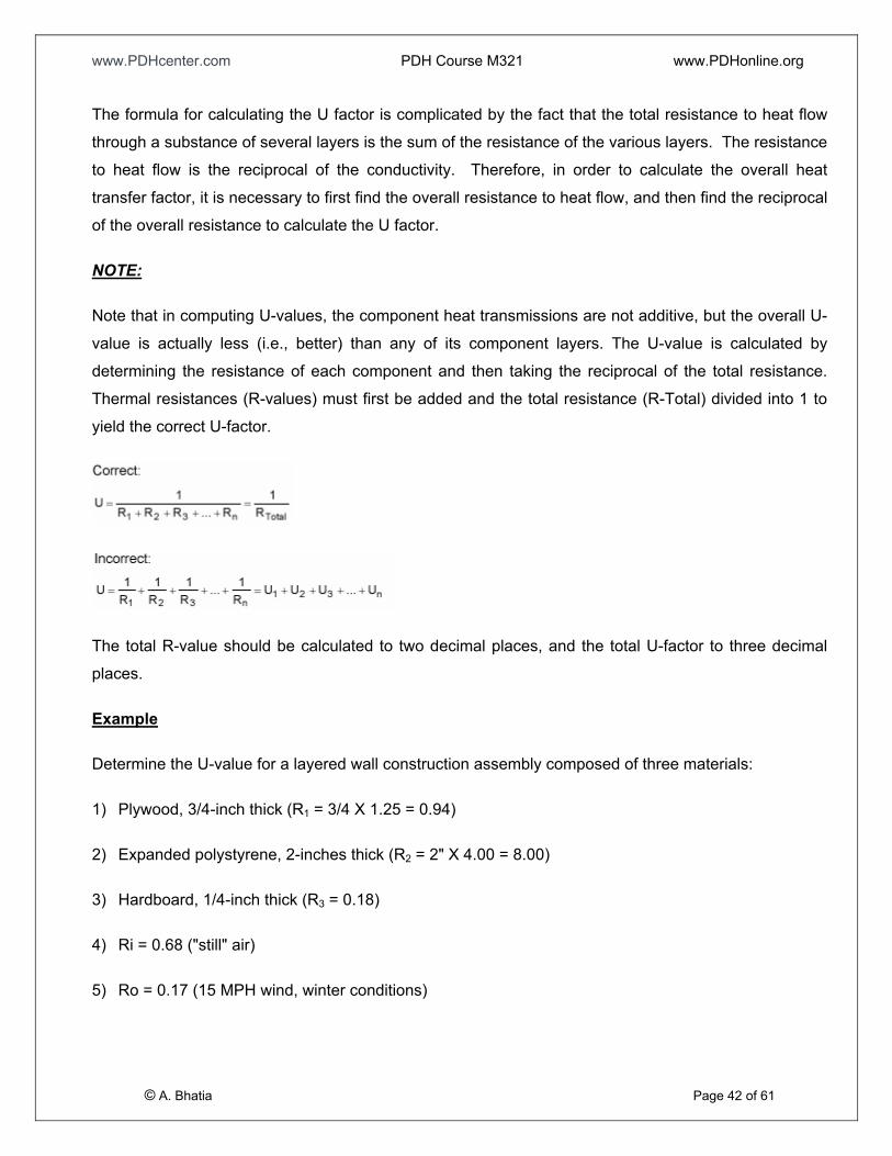
NOTE:
Note that in computing U-values, the component heat transmissions are not additive, but the overall U-
value is actually less (i.e., better) than any of its component layers. The U-value is calculated by
determining the resistance of each component and then taking the reciprocal of the total resistance.
Thermal resistances (R-values) must first be added and the total resistance (R-Total) divided into 1 to
yield the correct U-factor.
The total R-value should be calculated to two decimal places, and the total U-factor to three decimal
places.
Example
Determine the U-value for a layered wall construction assembly composed of three materials:
1) Plywood, 3/4-inch thick (R1 = 3/4 X 1.25 = 0.94)
2) Expanded polystyrene, 2-inches thick (R2 = 2" X 4.00 = 8.00)
3) Hardboard, 1/4-inch thick (R3 = 0.18)
4) Ri = 0.68 ("still" air)
5) Ro = 0.17 (15 MPH wind, winter conditions)
© A. Bhatia Page 42 of 61
www.PDHcenter.com PDH Course M321 www.PDHonline.org
R1
x 1
k1
RR2 3
x2
x3
k2
k3
Q Q
T i
T1
TT o
3
T2
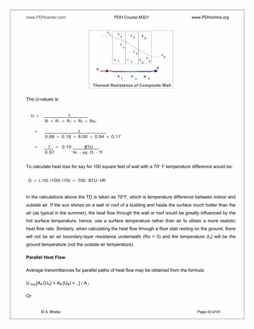
Thermal Resistance of Composite Wall
The U-values is:
To calculate heat loss for say for 100 square feet of wall with a 70° F temperature difference would be:
In the calculations above the TD is taken as 70°F, which is temperature difference between indoor and
outside air. If the sun shines on a wall or roof of a building and heats the surface much hotter than the
air (as typical in the summer), the heat flow through the wall or roof would be greatly influenced by the
hot surface temperature; hence, use a surface temperature rather than air to obtain a more realistic
heat flow rate. Similarly, when calculating the heat flow through a floor slab resting on the ground, there
will not be an air boundary-layer resistance underneath (Ro = 0) and the temperature (to) will be the
ground temperature (not the outside air temperature).
Parallel Heat Flow
Average transmittances for parallel paths of heat flow may be obtained from the formula:
U avg [AA (UA) + AB (UB) +...] / A B t
© A. Bhatia Page 43 of 61
Or
www.PDHcenter.com PDH Course M321 www.PDHonline.org
U avg = [1/ (RA /AA) + 1/(RB/AB BB)...]/AT
Where:
• AA, AB, etc. = area of heat flow path, in ft B
2
• UA, UB, etc.= transmission coefficients of the respective paths B
• RA, RB, etc.=thermal resistance of the respective paths B
• AT= total area being considered (AA+AB+...), in Ft B
2
Such an analysis is important for wall construction with parallel paths of heat flow when one path has a
high heat transfer and the other a low heat transfer, or the paths involve large percentages of the total
wall with small variations in the transfer coefficients for the paths.
Heat flow through air
• Wind outdoors has to be taken into consideration.
• Air films both inside and outside building envelope affects heat flow.
© A. Bhatia Page 44 of 61
• A combination of dead air spaces and reflective surfaces produce very efficient insulation
materials.
www.PDHcenter.com PDH Course M321 www.PDHonline.org
SECTION – 4 HEAT GAIN AND HEAT LOSS IN BUILDINGS
Each building has a characteristic exterior air temperature, known as the balance point temperature, at
which the building in use would be able to support thermal comfort without the need for a heating or
cooling system. At the balance point temperature, which is strongly influenced by internal loads and
envelope design, building heat gains and losses are in equilibrium so that an appropriate interior
temperature will be maintained naturally and without further intervention. When the outside air
temperature falls below the balance point temperature, heat losses through the building envelope will
increase – and interior air temperature will drop unless heat is added to the building to compensate. A
system that provides such additional heat is called a space (or building) heating system. When the
outside air temperature exceeds the balance point temperature, heat gain through the building
envelope will upset thermal equilibrium and cause the interior air temperature to rise. A system that
removes such excess heat is called a cooling system.
There are two distinct components of the air conditioning load; (1) the sensible load (heat gain/loss)
and (2) the latent load (water vapor gain).
Sensible Loads - Sensible heat gain is the direct addition of heat to a space,which shall result in
increase in space temperatures. The factors influencing sensible cooling load:
• Solar heat gain through building envelope (exterior walls, glazing, skylights, roof, floors over
crawl space)
• Heat flow from warmer surroundings (partitions that separate spaces of different temperatures)
• Ventilation air and air infiltration through cracks in the building, doors, and windows
• Heat flow into the space from energy consuming objects within the space; these objects usually
include: Lights, Electrical and electronic appliances, cooking or kitchen appliances, Occupants
within the space etc.
Latent Loads - A latent heat gain is the heat contained in water vapor. Latent heat does not cause a
temperature rise, but it constitutes a load on the cooling equipment. Latent load is the heat that must be
removed to condense the moisture out of the air. The sources of latent heat gain are:
© A. Bhatia Page 45 of 61
• Ventilation air and air infiltration through cracks in the building, doors, and windows
www.PDHcenter.com PDH Course M321 www.PDHonline.org
• Moisture generated within the space from moisture generating objects. These objects usually
include: occupants within the space (breathing), moisture generated by cooking or warming
appliances, industrial or production machinery which evaporates water, housekeeping, floor
washing etc.
The total cooling load is the summation of sensible and latent loads.
Solar radiation
Heat gains from the sun can lead to increases in internal temperatures beyond the limits of comfort. It is therefore necessary to determine the amount of solar radiation that is transmitted into buildings
through; windows, walls, roof, floor and by admitting external air into the building.
Classification of solar radiation: Total solar heat quantity falling on a surface consists of (1)
unshaded direct radiation, (2) unobstructed diffuse radiation from sky, and (3) reflected solar radiation
from adjacent surfaces.
• Direct radiation: Radiation that reaches earth's surface direct from the sun. On a clear day
radiation intensity may range from 400 to 450 BTUH per square foot of surface area.
• Diffuse radiation: Radiation that has been scattered or re-emitted. As solar radiation, making
use of electromagnetic waves, passes through the atmosphere, a portion of the energy is
reflected, scattered, and absorbed by smoke, dust, gas molecules and water vapor. The sky
looks blue because of scattering of the radiant energy corresponding to blue part of the
electromagnetic spectrum, having shorter wavelengths; red at sunset results from the scattering
of longer wavelengths corresponding to the red part of the spectrum.
• Solar heat gain through windows depends on its location on the earth's surface (latitude), time
of the day, day of the year, and the direction it faces.
Formula for calculation of solar heat gain:
BTUH = SHGF * A * SC
Where
© A. Bhatia Page 46 of 61
• SHGF = solar heat gain factor that specifies solar radiation in BTUH/sq-ft.
www.PDHcenter.com PDH Course M321 www.PDHonline.org
• A = glass area in sq-ft, and
• SC = shading coefficient that specifies the percentage of solar heat passing through the glass.
Some radiation may be absorbed by the ozone layer in the upper atmosphere and some by water vapor
near the earth's surface.
HEAT FLOW THROUGH BUILDING ENVELOPE
Solar Load through Roof and Wall
Formula for calculation of sensible heat gain/loss through a building envelope (roof, walls and
conduction through glass)
BTUH = U*A*TD
Where
• Rate of heat flow (U)
o U-value for roof, wall, floor, etc. may be calculated by finding the resistance of component
materials, air films, and internal air spaces.
o For floors and walls in contact with the ground, use (1) a factor of 2 @temperature 10oF or
above, (2) a factor of 4 @temperature below 10oF.
o Use overall U-values for different types of windows (residential or commercial) and not the
center of the glazing.
[See 1997 ASHRAE Fundamentals, Chapter 24 or 2001 ASHRAE Fundamentals, chapter 25].
• Area of construction (A)
o Calculate wall, roof, window, door, and floor areas from architectural drawings.
• Temperature difference (TD)
© A. Bhatia Page 47 of 61
o Calculate the difference between inside and outside temperatures of the building envelope.
www.PDHcenter.com PDH Course M321 www.PDHonline.org
TD is OK for heat loss calculations but for cooling load calculations, another parameter CLTD =
Cooling Load Temperature Difference is rather used to account for thermal mass dynamics. The
actual equation for cooling load is
BTUH = U * A * (CLTD)
Where
o CLTD = Cooling Load Temperature Difference (in °F) for roof, wall or glass. For winter
months CLTD is (Ti - To) which is temperature difference between inside and outside. For
summer cooling load, this temperature differential is affected by thermal mass, daily
temperature range, orientation, tilt, month, day, hour, latitude, solar absorbance, wall facing
direction and other variables and therefore adjusted CLTD values are used. Refer 1997
ASHRAE Fundamentals, Chapter 28, tables 30, 31, 32, 33 and 34.
The thermal storage concept is discussed further, later in this section.
Solar Load through Glazing
The treatment of heat transfer through window glass, skylights and plastic sheets is different. Heat
transfer through glazing is both conductive and transmission. It is calculated in two steps:
Step # 1
The equation used for sensible loads from the conduction through glass is:
BTUH = U * A * (CLTD)
Where
o U = Thermal Transmittance for roof or wall or glass. See 1997 ASHRAE Fundamentals,
Chapter 24 or 2001 ASHRAE Fundamentals, chapter 25. (Unit- Btu/Hr Sq-ft °F)
o A = area of roof, wall or glass calculated from building plans (sq-ft)
o CLTD = Cooling Load Temperature Difference (in °F) for glass. Refer 1997 ASHRAE
Fundamentals, Chapter 28, tables 30, 31, 32, 33 and 34.
© A. Bhatia Page 48 of 61
Step # 2
www.PDHcenter.com PDH Course M321 www.PDHonline.org
The equation used for radiant sensible loads from the transparent/translucent elements such as window
glass, skylights and plastic sheets is:
BTUH = A * (SHGC) * (CLF)
Where
o A = area of roof, wall or glass calculated from building plans (sq-ft)
o SHGC = Solar Heat Gain Coefficient. See 1997 ASHRAE Fundamentals, Chapter 28, table 35
o CLF = Solar Cooling Load Factor. See 1997 ASHRAE Fundamentals, Chapter 28, table 36.
Partitions, Ceilings & Floors
The equation used for sensible loads from the partitions, ceilings and floors:
BTUH = U * A * (Ta - Trc)
Where
• U = Thermal Transmittance for roof or wall or glass. See 1997 ASHRAE Fundamentals,
Chapter 24 or 2001 ASHRAE Fundamentals, and Chapter 25.
• A = area of partition, ceiling or floor calculated from building plans
• Ta = Temperature of adjacent space (Note: If adjacent space is not conditioned and
temperature is not available, use outdoor air temperature less 5°F)
• Trc = Inside design temperature of conditioned space (assumed constant)
Outdoor Air
Outside air is needed for 3 main reasons:
© A. Bhatia Page 49 of 61
• Required to maintain Indoor Air Quality for the occupants (see ASHRAE Standard 62 for
minimum ventilation requirements). A minimum air exchange is necessary to decrease carbon
dioxide buildup and remove odors. Such air exchange may take place either through infiltration
or ventilation.
www.PDHcenter.com PDH Course M321 www.PDHonline.org
• Required to maintain space pressurization and prevent infiltration.
• Required as make-up air to compensate for what is compulsorily exhausted from restrooms,
pantry, and kitchen and janitor areas.
Ventilation
• Ventilation refers to air brought into building by choice, intentionally.
• May either be provided mechanically or by natural means.
• The outside air that is allowed to enter the building through ventilation must also be conditioned
(heated, cooled, humidified, dehumidified, or cleaned).
• Rate of ventilation determined by the requirements based on number of occupants and their
activities.
• Recommended levels calculated either in terms of CFM per person or CFM per square foot.
• Mechanical ventilation is not usually required for small, residential buildings; infiltration (some
quantity of air infiltrates, if the building is not hermetically sealed) is sufficient to furnish enough
air change for such buildings.
Infiltration
• Leakage around doors and windows and around walls due to outdoor air pressure.
• Occurs in an uncontrolled manner. Winds on the windward side of the building blow outside air
into the indoor spaces, displacing conditioned air that leaves through similar opening on the
leeward side of the building where low outside air pressure creates suction.
• The outside air that enters the building must be conditioned (heated, cooled, humidified,
dehumidified, or cleaned).
© A. Bhatia Page 50 of 61
• Two methods for calculation of infiltration in buildings: crack length method and air change
method.
www.PDHcenter.com PDH Course M321 www.PDHonline.org
• Crack length method: Expresses air flow rate per unit length of crack (e.g. a metal framed
hinged window may have an infiltration of 0.35 CFM per foot of crack); requires specific
information about the dimensions and construction details of doors, windows, or other openings.
o The above method can also be expressed in terms of air flow rate per unit area of door
or window (e.g. an operable glass window has a rate of infiltration of 0.5 CFM per square
foot of the window area; the rate is about 0.25 CFM per square foot for fixed glass
windows).
o The quantity of infiltration depends on the kind or width of crack and the pressure
difference due to wind velocity. It is common to use a wind velocity of 15 mph for normal
design conditions.
• Air change method: This method takes into account total replacement of inside air by outdoor
air in terms of a unit called air change.
o When construction method and related crack lengths cannot be accurately evaluated,
the air change method may be used as an alternative.
o An air change having a value of 1 per hour means that all air in a building is replaced by
outside air every hour.
o Formula used for conversion of air change rate to CFM:
(Volume of building)*(Air change rate)/60 = CFM.
Calculation of Heat Gain / Heat Loss due to outside air (OA)
Heat gain/heat loss due to OA has two components: sensible and latent.
• Formula for calculation of sensible heat due to OA:
BTUH = 1.08*CFM*TD
• Formula for calculation of latent heat due to OA:
BTUH = 0.68*CFM*GD
© A. Bhatia Page 51 of 61
• Formula for calculation of total heat due to OA:
www.PDHcenter.com PDH Course M321 www.PDHonline.org
BTUH total = 4.5 * CFM * ED
Explanation of variables:
Value of CFM to be used in calculation
• Outside air rate both due to infiltration and ventilation should be found out. The rate which is
larger should be used in the calculation of heating/cooling load.
Value of TD to be used in calculation
• TD is the temperature difference of the outside air dry-bulb temperature (°F) and the dry-bulb
temperature of air leaving the cooling coil (°F). It is also represented as (To – Tc).
Value of GD to be used in calculation
• GD is the difference of the humidity ratio of outside air (grains of moisture) and humidity ratio of
air leaving the cooling coil (grains of moisture). It is also represented as (wo – wc).
Value of ED to be used in calculation
• ED is the difference in enthalpy of outside air (Btu per lb of dry air) and enthalpy of air leaving
the cooling coil (Btu per lb of dry air). It is also represented as (ho – hc).
Some explanations of the constants used in OA heat transfer models
• Specific Heat: Quantity of heat required to raise the temperature of one pound of a material by
1oF. Specific heat of air is 0.24 BTU/lb/1oF.
• Why a constant 1.08 in the sensible heat transfer model?
o At a rate of 1 CFM airflow, there are 60 such units in an hour (the hourly rate of airflow is
required to be known because heat flow is calculated in terms of per hour). 60 CFM of
air = 4.5 lbs of air.
o Heat required to raise the temperature of 4.5 lbs of air = 0.24*4.5 = 1.08 BTU/lb/oF.
• Why a constant of 0.68 in the latent heat transfer model?
© A. Bhatia Page 52 of 61
o Heat released in condensation of one pound of water = 1060 BTU.
www.PDHcenter.com PDH Course M321 www.PDHonline.org
o Heat released in condensation of one grain of water = 1060/7000 BTU.
o Assuming a moisture difference of one grain per pound between inside and outside air,
for 60 CFM of air there will be difference of 4.5 grains. Heat released in condensation of
that amount of water = (1060/7000)*4.5 = 0.68 BTUH.
INTERNAL LOADS
People
The human body generates heat within itself through the process of metabolism, and releases it by
conduction, convection, radiation, and evaporation from skin and clothing; and by convection and
evaporation in the respiratory tract. While part of this heat gain due to evaporation of moisture is latent,
the rest is sensible. The proportion of heat released in the form of sensible to latent heat depends on
the ambient dry bulb temperature and moisture content of the surrounding air. The total amount of heat
gain due to this factor depends on number of people, duration of occupancy, and activity level. Both
sensible and latent heat components should be calculated using following equations:
• The equation used in estimating sensible load due to occupants is:
BTUH sensible = N * (QS) * (CLF)
• The equation used in estimating latent load due to occupants is:
BTUH latent = N * (QL)
Where
• N = number of people in space.
• QS, QL = Sensible and Latent heat gain from occupancy is given in 1997 ASHRAE
Fundamentals Chapter 28, Table 3
• CLF = Cooling Load Factor, by hour of occupancy. See 1997 ASHRAE Fundamentals, Chapter
28, table 37.Note: CLF = 1.0, if operation is 24 hours or of cooling is off at night or during
weekends.
© A. Bhatia Page 53 of 61
Lighting
www.PDHcenter.com PDH Course M321 www.PDHonline.org
Electric light fixtures convert electrical power into heat and light. Even light is eventually converted into
its equivalent heat energy in the space; so, in effect, all electrical power entering a light fixture ends up
as heat in a space. The lights results only in sensible heat gain and is given be equation:
BTUH = 3.41 * W * FUT * FBF * (CLF)
Where
• W = Installed lamp watts input from electrical lighting plan or lighting load data
• FUT = Lighting use factor, as appropriate
• FBF = Blast factor allowance, as appropriate
• CLF = Cooling Load Factor, by hour of occupancy. See 1997 ASHRAE Fundamentals,
Chapter 28, Table 38. Note: CLF = 1.0, if operation is 24 hours or if cooling is off at night or
during weekends.
[Simple method of estimating heat gain due to lighting: BTUH = 3.4 * watts/sq-ft * floor area].
Equipment
There is almost an infinite variety of equipment that contributes to heat gain to the conditioned space.
The designer has to be thorough in identifying all the heat-producing equipment in a given space. In
order to calculate heat gain due to the effect of equipment, the formula for lighting may be used as an
approximation. Three different equations are used under different scenarios:
• Heat gain of power driven equipment and motor when both are located inside the space to be
conditioned
Q = 2545 * (P / Eff) * FUM * FLM
Where
• P = Horsepower rating from electrical power plans or manufacturer’s data
• Eff = Equipment motor efficiency, as decimal fraction
© A. Bhatia Page 54 of 61
• FUM = Motor use factor (normally = 1.0)
www.PDHcenter.com PDH Course M321 www.PDHonline.org
• FLM = Motor load factor (normally = 1.0)
• Note: FUM = 1.0, if operation is 24 hours
• Heat gain of when driven equipment is located inside the space to be conditioned space and the
motor is outside the space or air stream
Q = 2545 * P * FUM * FLM
Where
• P = Horsepower rating from electrical power plans or manufacturer’s data
• Eff = Equipment motor efficiency, as decimal fraction
• FUM = Motor use factor
• FLM = Motor load factor
• Note: FUM = 1.0, if operation is 24 hours
• Heat gain of when driven equipment is located outside the space to be conditioned space and
the motor is inside the space or air stream
Q = 2545 * P * [(1.0-Eff)/Eff] * FUM * FLM
Where
• P = Horsepower rating from electrical power plans or manufacturer’s data
• Eff = Equipment motor efficiency, as decimal fraction
• FUM = Motor use factor
• FLM = Motor load factor
• Note: FUM = 1.0, if operation is 24 hours
© A. Bhatia Page 55 of 61
Kitchen appliances
www.PDHcenter.com PDH Course M321 www.PDHonline.org
The total residential equipment loads can be approximated by the major appliances in the kitchen. A
value of 1200 BTUH may be used as heat gain from residential kitchen appliances. (Note: for
commercial buildings, you do not have to calculate heat gain from kitchen appliances separately if you
have already calculated the heat gain from equipment.)
HEAT GAIN/LOSS IN BUILDINGS: OTHER FACTORS
Outdoor Design Conditions
The capacity calculations for the HVAC systems shall be based on the climatic information contained in
chapter 26 of 1997 ASHRAE Handbook of fundamentals. Design conditions for the United States
appear in Table 1a and 1b; for Canada in Tables 2a and 2b, and the international locations in Tables 3a
and 3b.
Table A-Winter Conditions:
• The information provided in table 1a, 2a and 3a are for heating design that include:
o Dry bulb temperatures corresponding to 99.6% and 99% annual cumulative frequency of
occurrence,
o Wind speeds corresponding to 1%, 2.5% and 5% annual cumulative frequency of
occurrence,
o Wind direction most frequently occurring with 99.6% and 0.4% dry-bulb temperatures
and
o Average of annual extreme maximum and minimum dry-bulb temperatures and standard
deviations.
Note that the percentages reflect annual cumulative frequency of occurrence of outdoor weather
conditions. No humidity data is provided for winter. Assume 100% RH
Table B-Summer Conditions
The information provided in table 1b, 2b and 3b are for cooling and humidity control that include:
© A. Bhatia Page 56 of 61
o Dry bulb temperature corresponding to 0.4%, 1.0% and 2.0% annual cumulative frequency
of occurrence and the mean coincident wet-bulb temperature (warm). [This implies that
www.PDHcenter.com PDH Course M321 www.PDHonline.org
0.4%, 1.0% and 2.0% of the time in a year, the outdoor air temperature will be above the
design condition.] These conditions appear in sets of dry bulb (DB) temperature and the
mean coincident wet bulb (MWB) temperature since both values are needed to determine
the sensible and latent (dehumidification) loads in the cooling mode.
o Wet-bulb temperature corresponding to 0.4%, 1.0% and 2.0% annual cumulative frequency
of occurrence and the mean coincident dry-bulb temperature
o Dew-point temperature corresponding to 0.4%, 1.0% and 2.0% annual cumulative frequency
of occurrence and the mean coincident dry-bulb temperature and humidity ratio (calculated
for the dew-point temperature at the standard atmospheric pressure at the elevation of the
station).
o Mean daily range (DR) of the dry bulb temperature, which is the mean of the temperature
difference between daily maximum and minimum temperatures for the warmest month
(highest average dry-bulb temperature). These are used to correct CLTD values.
Selecting Appropriate Outdoor Design Conditions
We have three Cumulative Achieved Periods for summer, two for winter. We have to decide which are
appropriate for design. Statistically we expect these design conditions to be exceeded as follows:
0.004*365 day/yr = 1.46 day/yr = 35 hrs/yr.
0.01*365 day/yr = 3.65 day/yr = 87.6 hrs/yr.
0.02*365 day/yr = 7.30 day/yr = 175.2 hrs/yr.
In effect, we are asked to make a cost/benefit choice in any design. Normally we do not design a
building with a cooling/heating so large that cooling/heating loads can be met for temperatures which
may occur only once in a hundred years. This would provide an expensive design and with operational
capabilities which are unlikely to be needed.
© A. Bhatia Page 57 of 61
In section – 1 “Comfort”, we noted that no single temperature/humidity combination satisfies everyone.
Based on the studies on Predicted Mean Vote (PMV) studies, the designer should select conditions that
will be considered tolerable for particular area of application. Here are some examples:
www.PDHcenter.com PDH Course M321 www.PDHonline.org
o If we are designing a 1 room apartment for college students low costs may be the major
consideration. In this case we may choose to design so that the system fails to meet normal
comfort conditions 2% of the time. (7.3 days/yr.)
o If we are designing a house for a middle income family, cost is still a factor but the family
may be less willing to compromise comfort. Here we may choose to design which fails to
meet design conditions 1% of the time (3.65 days/yr)
o If we are designing a computer room for an expensive main-frame computer, we may want
to provide maximum “comfort” for the system. Here we would design for the 0.4% design
condition. (1.7 days/yr.)
• Winter design conditions shall be based on the 99.6 percent column dry bulb temperature in the
ASHRAE Fundamentals Volume.
• For water-cooled heat rejection equipment (such as cooling tower) use ASHRAE 1% wet bulb
and for air-cooled use ASHRAE 1% dry bulb conditions.
• Base the selection of evaporative equipment on the 2.5% wet bulb temperature. For
applications where maintaining indoor temperature or humidity conditions is critical, the designer
may use the corresponding 1.0% temperatures.
• For the selection of condensers and condensing units that will be subjected to unusually high
radiation heat gain, add 3°C (5°F) to the dry bulb temperature specified above.
• Outdoor design temperature for heating to prevent freezing conditions should be based upon
the 99% dry bulb temperature.
• Special purpose facilities will require special definition of appropriate interior design conditions.
Indoor Design Conditions
Indoor cooling and heating design temperatures should be based upon local energy codes. Design
conditions for specific occupancies are specified in ANSI/ASHRAE 55-1992.
© A. Bhatia Page 58 of 61
For most of the comfort systems, the recommended indoor temperature and relative humidity are:
www.PDHcenter.com PDH Course M321 www.PDHonline.org
• Summer: 73 to 79°F; The load calculations are usually based at 75ºF dry bulb temperatures &
50% relative humidity
• Winter: 70 to 72°F dry bulb temperatures, 20 - 30 % relative humidity
These are design conditions and not operating limits. All thermostats shall be adjustable between 60 to
85°F).
Thermal mass dynamics
Heat Gain: The heat gain for a building is a simultaneous summation of all external heat flows plus the
heat flows generated inside the building. The heat gain varies throughout the 24 hours of the day, as
the solar intensity, occupancy; lights, appliances etc keep varying with time.
Cooling load: The cooling load is an hourly rate at which heat must be removed from a building in
order to hold the indoor air temperature at the design value. In other words, cooling load is the capacity
of equipment required to account for such a load.
Theoretically, it may seem logical to address that the space heat gain is equivalent to space cooling
load but in practice “Heat gain ≠ cooling load.”
The primary explanation for this difference is the time lag or thermal storage affects of the building
elements. Heat gains that enter a building are absorbed/stored by surfaces enclosing the space (walls,
floors and other interior elements) as well as objects within the space (furniture, curtains etc.) These
elements radiates into the space even after the heat gain sources are no longer present. Therefore the
time at which the space may realize the heat gain as a cooling load is considerably offset from the time
the heat started to flow. This thermal storage effect is critical in determining the instantaneous heat gain
and the cooling load of a space at a particular time.
Here are few definitions related to Heat absorption
Radiant heat: A large portion of heat gain by an envelope is radiant that does not immediately heat up
a space; it must first strike a solid surface and be absorbed and then radiated back into the space.
© A. Bhatia Page 59 of 61
Temperature difference: As radiant heat strikes a solid surface, some of it is absorbed, raising the
temperature at the surface above that inside the material and above that of the air adjacent to the
surface. This temperature difference causes heat flow into the material.
www.PDHcenter.com PDH Course M321 www.PDHonline.org
Thermal storage: Heat conducted into the material is stored, and heat convected into the air becomes
heat gain to the space. The proportion of radiant heat being stored depends on (1) the ratio of the
thermal resistance into the material to the thermal resistance of the air film, and (2) the temperature
difference. When the temperatures of the air and solid material start out equal, the majority of the
absorbed heat is stored in the material. As the process of storing radiant heat continues, the inside of
the material becomes warmer, which slows down the rate of heat transfer and storage of heat.
Thermal capacity: Heat is stored in building materials and furnishings the same way that sponge
soaks up water. The capacity of a material to store heat depends upon the quantity (mass) present and
its characteristic specific heat (Btu/lb-°F). As mass gets warmer, its capability to store heat decreases,
just as a sponge cannot absorb any more water when it is saturated. The magnitude of the heat storage
potential of a material depends on its thermal or heat-holding capacity. The thermal capacity of a
material is its weight times its specific heat, and thus is directly proportional to its weight:
Thermal capacity = specific heat * weight
Initial cooling load: In an air-conditioned space, the accumulation of heat during the day is stored in
the building envelope. When the cooling system is shut off during the night, transmission of heat
through the building envelope continues either into or out of the building, depending on the outside air
temperature. If the night time outdoor temperature is cooler than the indoor temperature, the heat may
be lost to the surrounding environment, so heat stored in the building envelope will be gradually
released outside. When the outside temperature is warmer than the indoor temperature, heat continues
to build up in the space, some of it flowing into the solid materials, where it is stored. This represents an
initial cooling load of the air-conditioning equipment when it is turned on again.
Initial heating load: During heating season, heat is discharged from the solid materials overnight when
the thermostat is set back. The mass must then absorb heat during a warm-up period to raise its
temperature. The bulk of the heating load during the warm-up period is attributable to the collective
mass.
© A. Bhatia Page 60 of 61
Mass arrangement of buildings: The magnitude and configuration of the mass are also important
factors that affect the heat storage capacity of buildings. The building can be so designed as to store
heat from the sun and the occupants that can be used to provide heat at night. In commercial buildings,
the thermal lag can be designed to last overnight until morning so that the building doesn't have to be
warmed back after setting back the thermostat at night. The heat storage and subsequent rate of
www.PDHcenter.com PDH Course M321 www.PDHonline.org
release into or out of the building depend on the thermal storage capacity and the magnitude of the
indoor-outdoor temperature difference.
• Thermal lag: If the building envelope contains a large quantity of mass, it will store a large
quantity of heat and cause a delay in heat transmission. This delay is called thermal lag. The
more the mass, the longer the delay. Thermal lag can be of several hours or even several days.
Determination of the need for thermal storage: The desirability of high or low thermal storage mass
depends on the climate, site, interior design condition, and operating patterns. For example, high
thermal storage mass is advantageous when outdoor temperature swings widely above and below
recommended indoor temperature.
Moisture Transfer in Building Envelope
In most comfort air-conditioning systems, usually only the space temperature is controlled within limits.
A slight variation of the space relative humidity during the operation of the air system is often
acceptable. Therefore, the store effect of moisture is ignored except in conditioned spaces where both
temperature and relative humidity need to be controlled or in a hot and humid area where the air
system is operated at night shutdown mode. In most cases, latent heat gain is considered equal to
latent cooling load instantaneously.
Moisture problems
Air leakage and its associated water vapor infiltrate or exfiltrate through the cracks, holes, and gaps
between joints because of poor construction of the building envelope. The driving potential of this air
leakage and associated water vapor is the pressure differential across the building envelope.
Types of problem: Problems involving moisture may arise from changes in moisture content, the
presence of too much moisture, or the problems associated with its change of state. Of particular
interest is the change of the vapor to either liquid or to solid state, called condensation. Specifically,
there are three types of moisture problems in building construction: (1) visible condensation, (2)
concealed condensation, and (3) extremely low humidity.
© A. Bhatia Page 61 of 61
Visible condensation: Occurs when any interior surface is colder than the dew point of the nearby air.
Once the air temperature drops below its dew point, moisture is released on the surface. The loss of
moisture from the air causes a reduction of vapor pressure which then draws moisture in from the
www.PDHcenter.com PDH Course M321 www.PDHonline.org
surrounding air. This moisture also condenses, causing a continuous migration of moisture toward the
cold surface. Possible solutions to visible condensation problem are:
• Insulate interior surfaces, cold water pipes and ductwork
• Provide enough air motion
• Reduce the moisture content of air
• Ventilate moist air out of the space
• Reduce ventilation rates when the dew point is higher outside than inside
• Artificially warm the cold surfaces
• Mechanically dehumidify the air
Concealed condensation: Is caused by a higher concentration of water vapor inside than outside.
When there is a higher concentration of water vapor inside then outside, the vapor pressure is also
higher on the inside. This represents a driving force causing a diffusion of moisture through the building
envelope. The build-up of vapor pressure within the building is a function of the amount of vapor in the
air, its inability to escape, and the air temperature.
• Effects: Condensation within the envelope construction leads to deterioration of materials, paint
peeling, and insulation.
• Remedy: 1) dehumidify the interior space; 2) provide tightly sealed vapor barriers (should be
applied to the heated side); 3) ventilate the wall cavity.
© A. Bhatia Page 62 of 61
Extremely low humidity: An extremely low RH can cause physical discomfort and may also cause
damage to materials (e.g. shrinkage of porous materials, de-lamination of furniture and paneling, cracks
in wood, loosening of joints, etc.). The minimum RH that should be normally maintained is 20 percent.
www.PDHcenter.com PDH Course M321 www.PDHonline.org
SECTION – 5 HVAC NOISE & VIBRATION
Noise can have a significant impact upon the comfort and welfare of occupants. Unwanted noise makes
a workplace uncomfortable and less productive. When people are surveyed about workplace comfort,
their most prevalent complaints involve the heating, ventilating and air-conditioning (HVAC) systems.
The problems they cite most frequently, aside from temperature control, have to do with excessive
noise and vibration.
The HVAC industry has established noise criteria (NC) values for evaluating the acceptability of sound
levels. NC values for different types of buildings range from 30 to 40 decibels. A decibel is a unit of
comparative sound measurement (a whispered conversation at a distance of 6 ft. from the ear, for
example, has a sound pressure level of 30 decibels). The noise level and vibration transmission can be
partially controlled by mechanical isolation, shields, baffles, and acoustical liners. Massive concrete
pads and vibration isolators are placed between the equipment and the building to avoid transmission
of vibration and noise through the structure. Equipment rooms can be acoustically isolated if necessary.
Architectural acoustics
Acoustics is the science of sound. It relates to recorded music, to speech and hearing, to the behavior
of sound in concert halls and buildings, and to noise in our environment. It is the technology of
designing spaces and systems that meet our auditory needs. Architectural acoustics deals with sound
in and around buildings of all kinds. Good acoustical design ensures the efficient distribution of
desirable sounds as well as the exclusion of undesirable sound. All acoustical situations consist of
three parts: (1) source, (2) Path, and (3) Receiver.
SOUND
Sound may be defined as vibrations or pressure changes in an 'elastic' medium, such as air, water,
most building materials, and earth. The terms noise and sound are often used interchangeably, but the
term sound is generally used to describe useful communication or a pleasant sound; whereas the term
noise is generally used to describe an unwanted sound which interferes with speech.
© A. Bhatia Page 63 of 61
In examining building acoustics we are mainly concerned with sound vibrations through the air,
whereas in the subject of noise control we are equally concerned with vibrations transmitted through
solid materials such as pipe work, concrete plinths and building structures.
www.PDHcenter.com PDH Course M321 www.PDHonline.org
Cycle, period, and frequency of sound: A full circuit by a particle of a medium displaced by vibration
is a cycle. Time required to complete one cycle is called the period. Number of complete cycles per
second is the frequency of sound. Unit of frequency is Hertz (Hz).
Wavelength: The distance a sound wave travels during one cycle of vibration. Wavelength = Velocity of
sound/Frequency of sound.
Sound intensity: Sound travels freely in all directions (i.e. spherically). Sound intensity is the strength
of sound per unit area of a spherical surface.
The Decibel Scale
Sound power (generating from an equipment say a fan) and sound pressure (received by the ear) are
measured in dB (decibels). The decibel scale is used to measure sound intensity. In decibel scale,
• Minimum intensity of perceptible sound is given a value of 0
• Whole numbers are used and
• An increase of every ten units equals a doubling of loudness.
It is a logarithmic scale. When trying to calculate the additive effect of two sound sources, use the
approximation as below (note that the logarithms cannot be added directly).
o With two sound sources of equal dBs, the equivalent dB is the original plus 3 dB.
(Example: 60 dB + 60 dB = 63 dB)
o With two sound sources of unequal dBs, if difference is 10 dB or more, use higher dB.
(Example: 70 dB + 60 dB = 70 dB)
When specifying noise criteria for HVAC equipment reference is made to the sound power level and not
the sound pressure level.
Sound Power and Sound Pressure
© A. Bhatia Page 64 of 61
The difference between sound power and sound pressure is critical to the understanding of acoustics.
To understand the concept of sound power and sound pressure, an analogy can be made between a
www.PDHcenter.com PDH Course M321 www.PDHonline.org
noise source and a light bulb. A light bulb is rated to dissipate a particular number of watts of power.
The bulb will always dissipate the same amount of power independent of its surroundings or the
environments in which it is located. As an example, a 60W light bulb consumes 60W no matter where it
is screwed in. However, the same bulb may appear to brighten a room covered with shiny reflecting
walls more than another with dull black walls. The effects of distance, volume of space, absorbing and
reflecting surfaces etc. will combine to determine the resulting lighting level at any point.
This is an exact parallel to the acoustical situation. Sound Power is the amount of acoustical power a
source radiates in a non-reflective environment and is measured in Watts. Sound power is a fixed
property of a machine irrespective of the distance and environment. On the other hand, Sound pressure
is related to how loud the sound is perceived to be, and depends upon the distance from the source as
well as the acoustical environment of the listener (room size, construction materials, reflecting surfaces,
etc.). Thus a particular noise source would be measured as producing different sound pressures in
different spots. Theoretically, the sound pressure “p” is the force of sound on a surface area
perpendicular to the direction of the sound. The SI-units for the Sound Pressure are N/m2 or Pa.
Inverse-square law: Sound intensity decreases at a rate inversely proportional to the square of the
distance from the sound source. The relationship can be expressed as:
I = W/4�r2
Where
• I = sound intensity in watts per square centimeter
• W = sound power in watts
• r = distance from the sound source in centimeter.
If the distance is measured in feet, 4�r2 has to be multiplied by 930 (because 1 square foot equals 930
square centimeters).
SOUND PROPAGATION
Direct: Reaches the receiver directly from the source.
© A. Bhatia Page 65 of 61
Reflection: Occurs when sound waves bounce off a surface at the same angle at which it was incident
on the surface.
www.PDHcenter.com PDH Course M321 www.PDHonline.org
Diffraction: It is the bending or flowing of a sound wave around an object or through an opening.
Diffusion: Scattering or random distribution of sound from a surface.
Reverberation: Persistence of sound after source of sound has ceased. Results from repeated
reflections. Some reverberation is good (particularly for musical performances), but not always
desirable. Intelligibility and subjective quality of sound is rated by reverberation time (RT).
Reverberation Time (RT): It is the time required for sound to decay 60 dB after the source has
stopped producing sound. Reverberation time = 0.05 * volume of room/total absorption of sound. (Average
ceiling height in spaces with upholstered seats and absorptive rear walls is approximately related to
mid-frequency reverberation time. Ceiling height �20 * Mid-frequency Reverberation Time in Seconds.)
Echo: Distinct repetition of original sound clearly heard above the general reverberation. A reflected
sound can be perceived as discrete echo if the reflected sound wave is heard 0.05 second or later after
it was heard as a direct sound.
SOUND ABSORPTION
When sound energy strikes a surface, part of the energy is absorbed. Reverberation and echoes may
be controlled by effective use of sound absorption quality of a surface. Acoustic absorption is defined in
terms of an absorption coefficient. It is the ratio of absorbed sound intensity by a material to the
intensity of the sound source.
Absorption coefficient = absorbed sound intensity/total intensity of sound source.
Total absorption by a surface = surface area * absorption coefficient
Unit of sound absorption is Sabin.
RAY DIAGRAM
© A. Bhatia Page 66 of 61
Ray diagram is analogous to specular reflection of light. Analysis of ray diagrams can be used to study
the effect of room shape on the distribution of sound and to identify surfaces that may produce echoes.
A ray diagram shows both reflected and direct sound paths. The difference between these two paths is
called path difference (Path Difference = Reflected Path - Direct Path). A path difference in excess of
the distance that can be traveled by a sound wave in 0.05 seconds indicates that the reflected sound
can be perceived as discrete echo.
www.PDHcenter.com PDH Course M321 www.PDHonline.org
WEIGHTING NETWORKS
A-weighting network: Generally, the sensitivity of human hearing is restricted to the frequency range
of 20 Hz to 20,000 Hz. The human ear, however, is most sensitive to sound in the 400 to 10,000 Hz
frequency range. Above and below this range, the ear becomes progressively less sensitive. To
account for this feature of human hearing, sound level meters incorporate a filtering of acoustic signals
according to frequency. This filtering is devised to correspond to the varying sensitivity of the human
ear to sound over the audible frequency range. This filtering is called A-weighting. Sound pressure
level values obtained using this weighting are referred to as A-weighted sound pressure levels and are
signified by the identifier dBA. Simply speaking, it may be defined as a frequency-response adjustment
of a sound-level meter that makes its reading conform, very roughly, to human response.
C-weighted network: The C-weighted network provides un-weighted microphone sensitivity over the
frequency range of maximum human sensitivity (over 1000 Hz).
SOUND TRANSMISSION CLASS (STC) OF MATERIALS
STC is a single number rating of the air-borne transmission loss (TL) of a construction. It measures the
sound transmission loss (TL) of a construction at one-third octave band frequencies.
• For measurement, analysis, and specification of sound, the frequency range is divided into
sections or bands. One common standard division is into ten octave bands identified by their
mid-frequencies: 31.5, 63, 125, 250, 500, 1000, 2000, 4000, 8000, and 16000.
The STC of a given material is determined by comparing its measured TL values against a standard
STC contour using the following criteria:
• The maximum deviation of the test curve below the standard contour at any single test
frequency shall not exceed 8 dB.
• The sum of deviations below the standard contour at all frequencies of the test curve shall not
exceed 32 dB.
When the contour is adjusted to the highest value (in integral dB) that meets the above requirements,
the STC of the material would be the TL value corresponding to the intersection of the standard STC
contour and 500 Hz frequency ordinate.
© A. Bhatia Page 67 of 61
Noise from Ventilation and AC Systems
www.PDHcenter.com PDH Course M321 www.PDHonline.org
The HVAC noise that ultimately reach living/ working quarters are made up of
• Low-frequency fan noise - fans generally produce sound in 16-Hz through 250-Hz octave
bands; Variable-air-volume (VAV) boxes noise is usually in the 125-Hz through 500-Hz octave
frequency bands.
• Mid-frequency airflow or turbulence-generated noise - Velocity noise from airflow and turbulence
in a duct ranges from 31.5 Hz through 1,000 Hz.
• High-frequency damper and diffuser noises - Diffuser noise usually contributes to the overall
noise in the 1,000-Hz through 4,000-Hz octave bands.
Typical mechanical system noise is made up of a variety of noise components. Therefore the HVAC
designer has to deal with noise control at various frequencies. Noise in any HVAC system can be
measured as a function of frequency in decibels, typically divided into eight octave bands. That result is
then compared against a criteria curve, such as the noise criterion (NC) family of curves. “Private
offices are typically designed for NC 30 to 35, while open offices are designed for NC 40 to 45.
Experience has shown that sound levels in offices above NC 45 can start to create complaints.
HVAC Design Tips for Acoustically Sensitive Spaces
• Construction Materials: Construct wall and ceiling assemblies to absorb noise and lower
reverberation time. You have to at least double the absorption in a space before there is a
noticeable difference. Every time you double the absorption, the reverberant noise field is
reduced by 3 dB, which is classified as “just perceptible”.
Use high-STC (sound transmission class) materials to keep noise out. When the mass of a
barrier is doubled, the isolation quality (or STC rating) increases by approximately 5 dB, which is
clearly noticeable.
• Penetrations: Make sure all penetrations through sound isolation walls and ceilings are sealed
resiliently and airtight.
© A. Bhatia Page 68 of 61
• HVAC Equipment Location: Locate equipment that generates noise and vibration as far away
as practical from acoustically sensitive spaces. If an air handler is too close to a critical space,
the risk of excessive noise or vibration via every other potential path is greatly magnified.
www.PDHcenter.com PDH Course M321 www.PDHonline.org
• Variable Speed Options: Make sure fan motor can handle the speed change. Lowering fan
speeds and fan modulation provides opportunities to adjust noise levels.
• Duct Silencers: Sound attenuators are an effective means of reducing broadband noise as it
travels down a duct system, and have the advantage of predictable performance. Locate
silencers far enough upstream of any acoustically sensitive space to ensure that the noise they
generate is adequately attenuated before it reaches the occupied room.
• Duct-Borne Noise: The duct work that connects a fan or air handler to a room is a contained
system that will also connect the equipment noise and vibration to the room unless adequate
precautions are taken to attenuate the noise before it gets there. Add internally lined supply and
return path ductwork to unit or at least lining the last 7 feet of the duct work to the room.
• Return Air Path: Don’t forget that the return-air path is an equally important contributor to noise
problems. In fact, because return-air systems sometimes employ common plenums above
corridor ceilings, there may be less duct work in the return-air path to attenuate the noise, and
the transfer of return air from one space to another may be a significant breach of the sound
isolation between them.
• Velocity Noise: As conditioned air travels from a fan to an occupied room, it is subjected to
acceleration, deceleration, changes in direction, division and a variety of surfaces and
obstacles. Each of these effects disturbs the uniformity of the airflow and causes turbulence,
which in turn creates noise. Keep low airflow velocities throughout the duct systems serving
acoustically sensitive spaces.
• Ducts Shape: Rectangular ducts, particularly those with high aspect ratio can transmit
excessive noise if not properly supported. Round ducts are stronger and have better
aerodynamic characteristics, and therefore experience fewer noise problems.
• Terminal Units: Registers and diffusers should be selected to minimize noise output.
Equipment spaces should be separated as far as possible from spaces with demands for low
background sound levels. Avoid locating air terminals in close proximity to air-handling units.
Provide at least one change in direction between air terminals and air-handling units.
© A. Bhatia Page 69 of 61
• Vibration Isolation: Rotating or motor-driven machinery generates vibration energy that can
travel through a building's structure and radiate from the walls, floors and ceilings in the form of
www.PDHcenter.com PDH Course M321 www.PDHonline.org
airborne noise. Vibration is best controlled by decoupling the vibrating equipment from the
surrounding structure. This can involve spring mounts, elastomeric mounts, inertial bases,
floating floors and/or structural isolation joints. Any ducting, piping and conduit that are
connected to vibrating equipment must be isolated with flexible connections.
• Volume Dampers: Volume dampers are needed to limit the amount of air that is allowed down
the duct path. Unfortunately, dampers accomplish their volume control by pinching down the air
stream, increasing the pressure and consequently the noise wherever they occur. Never use
face dampers on the diffusers to adjust the air volume. The face dampers are essentially
exposed directly into the room and in acoustically sensitive spaces; they can generate audible
noise even if face dampers are left wide open. Adjust the volume upstream using opposed-
blade-type dampers.
HVAC noise and vibration control is a specialized field. Even with the best of intentions, there are
hundreds of ways to make acoustical blunders that can render a technical space virtually unusable.
There is no substitute for getting qualified help for the mechanical and acoustical design of HVAC
systems in a technical facility.
© A. Bhatia Page 70 of 61