inspecting hvac systems - nachi hvac systems ... section 5: heat fundamentals………… ... at . ~...
TRANSCRIPT

~ 1 ~
INSPECTING HVAC SYSTEMS
The purpose of this publication is to provide accurate and useful information for home
inspectors in order to perform an inspection of the heating, ventilation, and air-conditioning
(HVAC) system at a residential property. This manual covers the components of common
residential HVAC systems, including: warm-air, hydronic, steam and electric heating
systems; air-conditioning systems; and heat-pump systems. This guide also refers to the
InterNACHI Residential Standards of Practice with regard to recommended inspection
protocols. For more information, visit www.NACHI.org.
Authors: Ben Gromicko, Director of Online Education,
International Association of Certified Home Inspectors, Inc.
and Executive Producer, NACHI.TV
Nick Gromicko, Founder, International Association of
Certified Home Inspectors, Inc.
Graphics: Lisaira Vega, Graphics
Editor & Layout: Kate Tarasenko / Crimea River
To order online, visit: www.InspectorOutlet.com
© Copyright 2009-2012 International Association of Certified Home Inspectors
All rights reserved.
~ 2 ~
Table of Contents
Introduction…........................................................................................ 3
Section 1: Inspection Tools............................................................... 4
Section 2: Inspection Procedures……….………….......................... 6
Section 3: InterNACHI SOP……......................................................... 7
Section 4: Introduction to HVAC........................................................ 14
Section 5: Heat Fundamentals…………….…………......................... 15
Section 6: Identify and Describe Heating Systems......................... 18
Section 7: Gas, Gas Meters and Gas Pipes.………......................... 21
Section 8: Combustion Fundamentals……….………….................. 28
Section 9: Furnace Fundamentals……….…………......................... 33
Section 10: Warm-Air Heating Systems ……….………..................... 41
Section 11: Ducts…………………………….…………......................... 46
Section 12: Gas Furnaces…………….…….…………......................... 51
Section 13: Oil Furnaces……………...…….…………......................... 70
Section 14: High-Efficiency Heat Exchangers………......................... 79
Section 15: Coal, Wood and Multi-Fuel Furnaces.…......................... 80
Section 16: Hydronic Heating Systems..….…………......................... 81
Section 17: Steam-Heating Systems……….…………......................... 93
Section 18: Electric Heating Systems.…….…………......................... 96
Section 19: Steam and Hot-Water Space-Heating Boilers................ 98
Section 20: Air Conditioning……….……….…………......................... 106
Section 21: Heat Pumps…………….……….…………......................... 119
Section 22: Air Cleaners and Filters……….…………......................... 124
Section 23: Humidifiers……………..……….…………......................... 126
Section 24: Electric Furnaces……...……….…………......................... 128
INSPECTING HVAC SYSTEMS
~ 3 ~
INTRODUCTION
Learning Objectives
The inspector will demonstrate an understanding and comprehension of this material by
reading and studying the sections, taking the practice quizzes at the end of selected
sections, and by taking the online course in its entirety, and successfully passing a timed,
online exam. After successful completion of the online course, the student will be able to
perform an inspection of the HVAC system of a residential property, according to the
InterNACHI Standards of Practice for Performing a General Home Inspection.
Section 3 of this guide lists the particular section of the InterNACHI Residential Standards of
Practice pertaining to HVAC inspections. The full text of the Standards can be found online
at www.nachi.org/sop.htm.
~ 4 ~
SECTION 1: INSPECTION TOOLS
There are many tools that can be used when inspecting an HVAC system during
residential and commercial property inspections.
Flashlight
A flashlight is handy when inspecting the HVAC system. The outdoor condenser unit may be
in dark shade, under dense vegetation, or under a structural covering, such as a deck or
balcony. Inside the house, the HVAC system may be located in an attic, crawlspace or dark
basement. The inspection of the internal components of the system may require
illumination for some instances, including:
looking at the ribbon burners inside the combustion chamber;
looking at the interior of the combustion chamber through a viewing portal; or
looking at the air-filtering system that is installed inside the ductwork.
Moisture Meter
A moisture meter is used to detect and confirm moisture. It could be used to confirm
water and condensation problems, and to confirm that a building material is saturated with
water. High-efficiency condensing HVAC systems produce excessive condensate, and that
water needs to be controlled and discharged. Oftentimes, there are condensate lines or
sweating suction lines that leak onto building materials. Those leaks might be confirmed
with the use of a moisture meter. There are meters that are non-invasive and meters that
have invasive probes. Learn how to inspect for moisture during a property inspection at
www.nachi.org/moisturecourse.htm.
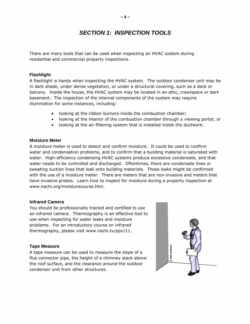
Infrared Camera
You should be professionally trained and certified to use
an infrared camera. Thermography is an effective tool to
use when inspecting for water leaks and moisture
problems. For an introductory course on infrared
thermography, please visit www.nachi.tv/ppv/11.
Tape Measure
A tape measure can be used to measure the slope of a
flue connector pipe, the height of a chimney stack above
the roof surface, and the clearance around the outdoor
condenser unit from other structures.
~ 5 ~
Screwdriver, Awl or Probe
These can be used to check for wood rot, and damage caused by a leak from a condensing
unit. A screwdriver may be needed to remove an access panel or some type of cover at the
HVAC system.
Binoculars
Binoculars can be used to look where physical, up-close access is restricted. When an air
conditioner is installed inside an attic, often, the water-leak catch pan will have a drainpipe
discharge at the eaves area. This drainpipe may not be readily visible from the ground
without binoculars.
Ladder
A ladder can be used to gain access to those higher-up areas that are not readily accessible
or visible from the ground level.
Magnet
A magnet can be used to tell the difference between aluminum pipes and steel pipes, and
galvanized steel flashing from copper flashing.
Coveralls
Coveralls or overalls protect your clothes. These are handy when moving through a
crawlspace and for inspecting under a low deck or porch.
Booties
You can put on some shoe booties prior to entering the
house that you are inspecting. Booties protect the floors.
This demonstrates care and consideration for your client's
property.
Gloves
Protect yourself. Use personal protection equipment (PPE),
including a simple pair of gloves. Gloves will protect your
hands from insect bites, scratches from vegetation, dirt and
soil, debris, splinters, and cuts from sharp edges of the HVAC
components.
Kneepads
It is important to protect your knees when crawling around, particularly when the ground
surface is rough and covered with rocks and stones. Kneepads are handy when kneeling in
front of the HVAC system and conducting your inspection.
~ 6 ~
SECTION 2: INSPECTION PROCEDURES
Many inspectors start their home inspection by inspecting the exterior first. This exterior
inspection might include the HVAC system. If there is a heating system that is fuel-fired,
the combustion gases and byproducts will require venting to the outside. The chimney
stack or flue exhaust pipes will need to be inspected. When you are conducting your roof
inspection, you might check the chimney or flue pipes that penetrate or come in contact
with the roof system. When inspecting the exterior grounds, you might stop at the outside
condenser unit and shift gears from inspecting the exterior to inspecting the HVAC system.
It is up to the inspector to choose the path to take when inspecting the systems of the
house. Do you inspect the exterior components of the HVAC system while you are
inspecting the exterior of the house?
Step Back
Figure out the various components of the house by stepping back. Identify the location of
some of the systems, such as the electrical service, HVAC unit, chimney structures,
plumbing entrance, landscaping features, property boundaries, shared utilities or
components, inspection restrictions, and other features and systems.
Move Closer
Next, move closer to the house and get a better, more detailed look. Many inspectors
follow the front walk or driveway that leads to the house as they approach. You may
choose a clockwise direction to move around the perimeter of the house. In this close-up
inspection of the exterior, you are looking for details of the HVAC system. Is there an air-
conditioning unit? Are there window or through-wall air-conditioner units? If there’s a
chimney, is there a heating system using it? Where does the air conditioner’s condensate
discharge? Get behind vegetation, and look under things, crawl under, reach up, look into,
and touch, measure and probe.
Time
The exterior, including the roof system and exterior HVAC components, may take up a third
of the total time of the home inspection.
Destroyer
Water (or moisture) is one of the main concerns when inspecting the HVAC system. Think
about water; it is the greatest destroyer of houses. Look for breaches and holes in the
siding where the exterior HVAC components are located. If the system is producing
condensate, figure out where it goes and how it’s being managed. For example, a suction
line of an operating air-conditioning system that is not insulated properly may produce
excessive condensate and humidity, under certain conditions. Pay attention to excessive
humidity levels that might be produced by a maladjusted component.
~ 7 ~
SECTION 3: InterNACHI SOP
The section covers specific items in the InterNACHI Standards of Practice for Performing a
General Home Inspection and how they relate to what an inspector may observe while
inspecting the HVAC system. At the end of this section, you should be able to:
list at least four things an inspector is required to inspect; and
list at least four things an inspector is not required to inspect.
InterNACHI Residential Standards of Practice
The following excerpts are from the InterNACHI Residential Standards of Practice as they
pertain to inspecting the heating, ventilation and cooling (HVAC) system of a residential
property, effective January 2008. The full text of the Standards can be found online at
www.nachi.org/sop.htm.
1. Definitions and Scope
1.1. A general home inspection is a non-invasive, visual examination of the accessible
areas of a residential property […], performed for a fee, which is designed to identify defects
within systems and components defined by these Standards that are both observed and
deemed material by the inspector. The scope of work may be modified by the Client and
Inspector prior to the inspection process.
I. The general home inspection is based on the observations made on the date of
the inspection, and not a prediction of future conditions.
II. The general home inspection will not reveal every issue that exists or ever could
exist, but only those material defects observed on the date of the inspection.
1.2. A material defect is a specific issue with a system or component of a residential
property that may have a significant, adverse impact on the value of the property, or that
poses an unreasonable risk to people. The fact that a system or component is near, at or
beyond the end of its normal, useful life is not, in itself, a material defect.
1.3. A general home inspection report shall identify, in written format, defects within
specific systems and components defined by these Standards that are both observed and
deemed material by the inspector. Inspection reports may include additional comments and
recommendations.
[…]

~ 8 ~
3.4. Heating
I. The inspector shall inspect:
A. the heating systems using normal operating controls, and describe the energy
source and heating method;
B. and report as in need of repair heating systems that do not operate;
C. and report if the heating systems are deemed inaccessible.
II. The inspector is not required to:
A. inspect or evaluate the interior of flues or chimneys, fire chambers, heat
exchangers, combustion air systems, fresh-air intakes, humidifiers,
dehumidifiers, electronic air filters, geothermal systems, or solar heating
systems.
B. inspect fuel tanks or underground or concealed fuel supply systems.
C. determine the uniformity, temperature, flow, balance, distribution, size, capacity,
BTU or supply adequacy of the heating system.
D. light or ignite pilot flames.
E. activate heating, heat-pump systems or other heating systems when ambient
temperatures or other circumstances are not conducive to safe operation or
may damage the equipment.
F. over-ride electronic thermostats.
G. evaluate fuel quality.
H. verify thermostat calibration, heat anticipation, or automatic setbacks, timers,
programs or clocks.
3.5. Cooling
I. The inspector shall inspect:
A. the central cooling equipment using normal operating controls.
II. The inspector is not required to:
A. determine the uniformity, temperature, flow, balance, distribution, size, capacity,
BTU or supply adequacy of the cooling system.
B. inspect window units, through-wall units, or electronic air filters.
C. operate equipment or systems if the exterior temperature is below 65°
Fahrenheit, or when other circumstances are not conducive to safe operation or
may damage the equipment.
D. inspect or determine thermostat calibration, cooling anticipation, or automatic
setbacks or clocks.
E. examine electrical current, coolant fluids or gases, or coolant leakage.
~ 9 ~
A Few Comments on the SOP
Home inspectors are not HVAC technicians or experts. We are not indoor air-quality
experts. We are property inspectors performing a property inspection according to a
Standards of Practice. We are strictly adhering to the InterNACHI Residential Standards of
Practice. We are employing the best non-invasive, visual-only inspection techniques to
perform the inspection of the HVAC system.
The inspection is not technically exhaustive. That means that the inspection is not a
comprehensive and detailed examination beyond the scope of a property inspection that
would involve or include, but would not be limited to: dismantling, specialized knowledge or
training, special equipment, measurements, calculations, testing, research, analysis or other
means.
Consider communicating to your client that there may be problems with the property that
exist during the inspection that will not be found or discovered because they are beyond the
scope of the home inspection.
We inspect the heating and cooling systems that are permanently installed at the
property. That means we have to visually look at readily accessible systems and
components safely, using normal operating controls, and accessing readily accessible panels
and areas in accordance with the Standards of Practice. Something is accessible if it can be
approached or entered by the inspector safely, without difficulty, fear or danger.
A component is a permanently installed or attached fixture, element or part of a system.
A blower fan of a forced warm-air furnace would be an example of a component of the
heating system.
We can activate a component. Activating means to turn on, supply power, or enable
systems, equipment, or devices to become active by normal operating controls. An
example would be to turn on only the blower fan using the thermostat control.
The condition of a component is the visible and conspicuous state of being of an object.
An inspector can report the component’s condition as being functional. A component can be
functional, or performing, or able to perform a function. A physically damaged blower fan is
a component in a condition that is not functional.
In the inspection report, we can describe, in written format, a system or component by its
type or other observed characteristics in order to distinguish it from other components used
for the same purpose.
An inspector is required to describe and identify, in written format, material defects
observed. A material defect is a condition of a residential real property, or any portion of it,
that would have a significant, adverse impact on the value of the real property, or that
involves an unreasonable risk to people on the property.
~ 10 ~
Inspection reports may contain recommendations regarding conditions reported, or
recommendations for correction, monitoring or further evaluation by professionals, but this
is not required.
The inspector shall inspect the heating systems using normal operating controls. There are
a few controls on a typical heating system, including the thermostat and service shut-off
switch.
We should be able to describe the energy source. The heating system may use a variety of
fuels, including electricity. We should describe the heating method. There are several ways
a heating system can distribute heat energy to the rooms and spaces of a building.
Inspectors need to inspect and be able to describe, in writing, how the system supplies heat
to the building. One example may be that the heating system is described as having No. 2
fuel oil as the energy source, and the system is a forced warm-air heating system that uses
a blower fan to distribute air through the ducts or pipes.
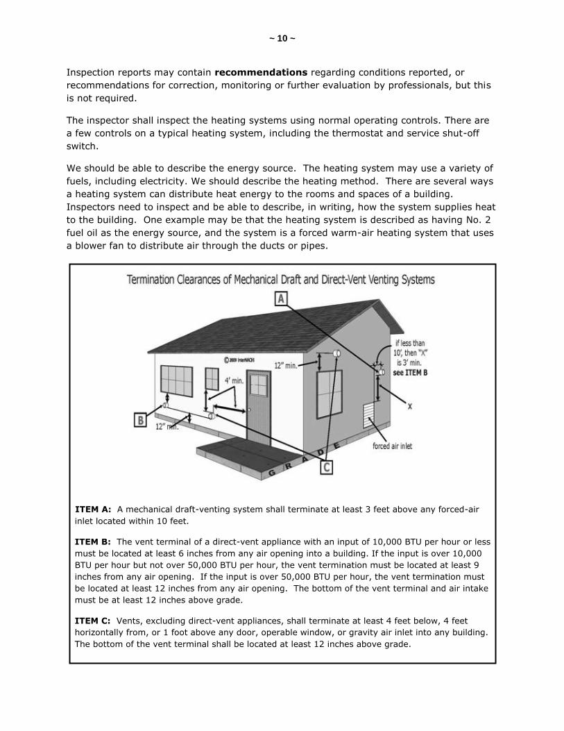
ITEM A: A mechanical draft-venting system shall terminate at least 3 feet above any forced-air
inlet located within 10 feet.
ITEM B: The vent terminal of a direct-vent appliance with an input of 10,000 BTU per hour or less
must be located at least 6 inches from any air opening into a building. If the input is over 10,000
BTU per hour but not over 50,000 BTU per hour, the vent termination must be located at least 9
inches from any air opening. If the input is over 50,000 BTU per hour, the vent termination must
be located at least 12 inches from any air opening. The bottom of the vent terminal and air intake
must be at least 12 inches above grade.
ITEM C: Vents, excluding direct-vent appliances, shall terminate at least 4 feet below, 4 feet
horizontally from, or 1 foot above any door, operable window, or gravity air inlet into any building.
The bottom of the vent terminal shall be located at least 12 inches above grade.
~ 11 ~
You are required to inspect the central cooling equipment using normal operating controls,
which include the thermostat and service shut-off switches. A window or through-wall air-
conditioning unit is not considered a central cooling system. You do not have to inspect a
window, through-wall or portable air-cooling equipment.
We are not required to use a ladder to inspect a house. Many inspectors use binoculars to
get a better look at components that are above their heads. When moving around the
house, look up and inspect the eaves, soffits and fascia components. Often, when a heating
or cooling system is installed in an attic space and the unit is producing condensate, there
will be a condensate drain line coming from the eaves and discharging to the exterior. That
small pipe may be difficult to see from the ground level without the use of binoculars.
If a heating or cooling system does not turn on or does not operate, an inspector should
note that in the inspection report. We are not required to ignite a pilot flame or turn on a
system that has been turned off. If you believe that activating an HVAC system may
actually cause damage to the system, you are not required to turn it on. For example, the
Standards specifically state that if the temperature is below 65° F, or when other
circumstances are not conducive to the safe operation of the cooling system, you are not
required to activate and inspect the cooling system.
If the heating or cooling system is deemed to be inaccessible, the inspector should report it
as such. Sometimes, there will be a condenser unit on top of a flat roof. If that roof is
inaccessible to the inspector, then so is the condenser unit. The inspector should report
how or why the particular system or component of that system was not accessible.
We are not required to inspect the interior of
flues and chimneys, fire chambers, heat exchangers
or combustion-air systems. The internal components
of the heating system are mostly beyond the scope of
a home inspection.
Humidifiers and dehumidifiers are beyond the scope
of a home inspection. We are not required to inspect
them. Sometimes, problems that are found at the
heating system are caused by a failure at the
humidifier. Humidifiers involve a lot of moisture,
water and condensate. If the humidifier is
malfunctioning, it could have a deleterious impact on
the heating system.
Geothermal and solar heating systems are not part of
a home inspection, according to the Standards.

~ 12 ~
We do not have to inspect the fuel storage tank if it is buried underground. You are
required to describe any visible fuel storage systems.
Inspectors do not have to determine the balance of the system, its BTU capacity, its size, or
its ability to adequately supply heated or cooled air to the building. You are not required to
determine (according to the InterNACHI Standards) the size, BTU or tonnage of the air-
conditioning system.
When the heating system is a boiler, the inspector should verify the presence or absence of
temperature/pressure-relief valves and/or Watts 210 valves. You are not required to test,
operate, open or close safety controls, manual stop valves and/or temperature or pressure-
relief valves.
At hydronic heating systems, you do not have to inspect water storage tanks, pressure
pumps or bladder tanks. On boiler systems, you do not have to determine the effectiveness
of anti-siphon or back-flow prevention devices.
Electronic air filters can be dangerous to inspect if they are not safely wired or properly
installed. You are not required to inspect electronic air-filtering devices.
The inspection is not required to include out-buildings. If there is a heating or cooling
system in the out-building, many inspectors will note the existence of the system and that
the additional structure, which includes the HVAC system, is beyond the scope of the
inspection. Many inspectors will charge an additional fee to inspect out-buildings.
In summary, an inspector should be able to inspect and describe the heating and cooling
systems. An inspection report shall describe and identify, in written format, the inspected
heating and cooling systems and components of the dwelling, and shall identify material
defects observed. Inspection reports may contain recommendations regarding conditions
reported, or recommendations for correction, monitoring or further evaluation by
professionals, but this is not required.
~ 13 ~
QUIZ 1
1. T/F: A home inspection is a non-invasive, visual examination of a residential dwelling.
True
False
2. T/F: A home inspector is required to describe the energy source.
True
False
3. T/F: A home inspector is not required to describe the heating method.
True
False
4. T/F: The inspector is required to inspect window and through-wall air-conditioning units.
True
False
Answer Key to Quiz 1
1. T/F: A home inspection is a non-invasive, visual examination of a residential dwelling. Answer: True
2. T/F: A home inspector is required to describe the energy source. Answer: True
3. T/F: A home inspector is not required to describe the heating method. Answer: False 4. T/F: The inspector is required to inspect window and through-wall air-conditioning units. Answer: False
~ 14 ~
SECTION 4: INTRODUCTION TO HVAC
This is a training manual on the principles of heating, ventilating and air conditioning
(HVAC) written for residential and commercial property inspectors. Heating, ventilation and
air conditioning are each used in an attempt to control the environment within an enclosure,
whether it is a room, space, or a dwelling.
People have been attempting to control heat and ventilation since prehistoric times. Over
the many centuries, the technology of heating has advanced from simple attempts to keep
the body warm to very sophisticated systems.
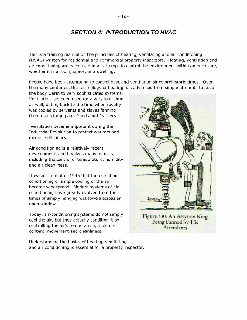
Ventilation has been used for a very long time
as well, dating back to the time when royalty
was cooled by servants and slaves fanning
them using large palm fronds and feathers.
Ventilation became important during the
Industrial Revolution to protect workers and
increase efficiency.
Air conditioning is a relatively recent
development, and involves many aspects,
including the control of temperature, humidity
and air cleanliness.
It wasn’t until after 1945 that the use of air
conditioning or simple cooling of the air
became widespread. Modern systems of air
conditioning have greatly evolved from the
times of simply hanging wet towels across an
open window.
Today, air-conditioning systems do not simply
cool the air, but they actually condition it by
controlling the air's temperature, moisture
content, movement and cleanliness.
Understanding the basics of heating, ventilating
and air conditioning is essential for a property inspector.

~ 15 ~
SECTION 5: HEAT FUNDAMENTALS
There are essentially three ways that heat moves from one area to another. When bodies
of unequal temperatures are near each other, heat leaves one body and goes to the other.
Heat moves from the hotter body, and the colder body absorbs it. The greater the difference
in temperature, the greater the rate of flow of the heat. Heat moves from one body to
another by the following ways:
radiation;
conduction; and
convection.
Radiation is the transfer of heat energy by electromagnetic wave motion. Heat is
transferred in direct rays. It travels in a straight line from the source to the body. The
closer you are to the hot object, the warmer you feel. The intensity of the heat radiated
from the object decreases as the distance from the object increases.
You feel cool in a room that has a cold floor, walls and ceiling. The amount of heat loss
from your body in that room depends on the relative temperature of the objects in that
room. The colder the floor is (relative to the temperature of your feet), the greater the heat
loss will be from your body just standing there. If the floor, walls and ceiling of that room
are relatively warmer than your body temperature, then heat will be radiated to your body
from those objects and surfaces.
~ 16 ~
Radiant heating in residential buildings includes piping and electrical wiring in floors, walls
and ceilings. Radiant heat emits in all directions. Reflective materials are commonly used
in a radiant heat-emitting system in order to direct and control where the heat is emitted.
Conduction is the transfer of heat from one molecule to another, or through one substance
to another. It is heat that moves from one body to another by direct contact. For example,
heat is transferred by conduction from a boiler heat exchanger to the water passing through
it. When you touch a suction line of an air conditioner and it feels warm, that’s heat energy
moving from the warm copper pipe to your (cooler) hand – by conduction.
Convection is known by most people from the phrase “heat rises.” Convection is the
transfer of heat by warming the air next to a hot surface, and then moving that warm air.
It’s the transfer of heat by the motion of the heated matter itself. The air moves from one
place to another, carrying heat along with it. Since warm air is lighter than the cool air
around it, the warm air (or heat) rises.
Warm fluids tend to rise while the surrounding cool fluids fall. This rising and falling tends
to form loops -- convective loops -- where warm air rises and cool air falls. Early warm-air
gravity furnaces used the principles of convective loops. In a gravity system, the warm air
rises and cool air falls, and this is how the gravity warm-air heating system circulated air.
Forced-air furnaces function primarily by convection. Heat is transferred to the air, and the
air is circulated throughout the house. Systems that heat water and use radiators and
baseboards as their heat-emitting devices use convection, and radiation, to a lesser extent.
A radiator needs air freely moving around it in order for it to be effective. Covers over
radiators might reduce the airflow around and through the radiator unit.
~ 17 ~
QUIZ 2
1. T/F: Heat moves from the warmer body, and the colder body absorbs it.
True
False
2. Heat can move from one body to another by _________.
ionization
radiation
capacitation
3. Forced-air furnaces function primarily by ________.
convection
radiation
conduction
Answer Key to Quiz 2
1. T/F: Heat moves from the warmer body, and the colder body absorbs it. Answer: True
2. Heat can move from one body to another by radiation.
3. Forced-air furnaces function primarily by convection.

~ 18 ~
SECTION 6: IDENTIFYING AND DESCRIBING HEATING SYSTEMS
According to the InterNACHI Standards of Practice, a home inspector shall describe and
identify, in written format, the inspected systems and components of the dwelling. In the
following sections, we will learn that most heating systems can be identified and described
in just four ways.
Heating Systems
There are many different types of heating systems. Each has its own characteristics that
can be used by a property inspector to identify and describe the type of heating system
being inspected. Most of these heating systems can be described according to one or more
of the following broad categories:
the heat-conveying medium;
the fuel used;
the nature of the heat; and
the efficiency and capacity of the system.
The heat-conveying medium is what carries the heat from the source to the enclosure being
heated. The fuel used is a distinguishing characteristic of a heating system. Wood, coal, oil
and gas are used to produce heat. Electricity may be considered a fuel, but it can also be
the heat-conveying medium. The nature of the heat is also a distinguishing characteristic.
For example, it could be steam, or heat produced by combustion. The efficiency and
capacity of the heating system can be cited to distinguish one heating system from
another.
These four categories alone are not enough for most inspectors to sufficiently identify and
describe the type of heating system that they are inspecting. The use of those previous
terms might be confusing to their clients. Other distinguishing characteristics and details
are needed in order to identify and describe different types of heating systems in a concise
manner that is specific to the property, as well as easily understood. Let’s take a look at
how heating systems can be identified and described in more detail, according to heat-
conveying mediums.
Heat-Conveying Mediums
For most inspectors, describing the heat-conveying medium is one of the main ways to
identify and describe different types of heating systems. There are four heat-conveying
mediums that can carry heat. They are air, water, steam and electricity.
~ 19 ~
For example, if the heating system is a high-efficiency, gas-fired furnace, then the heat-
conveying medium is air. The inspector would use the heat-conveying medium as part of
the identification and description of the heating system. In this example, the description
would be a warm-air heating system, or, even more accurately, a gas warm-air furnace.
Four Types of Heating Systems
Taking the previously listed four common heat-conveying mediums into consideration, most
heating systems can be identified and described by a property inspector using the following
four terms:
warm-air heating system;
hydronic heating system;
steam heating system; and
electric heating system.
Most heating systems can be described in those four ways. They can be accurately
identified and described using those terms, which are based on the four heat-conveying
mediums: air, water, steam, and electricity. Classifications of heating systems based on the
heat-conveying medium is a convenient method for property inspectors because it includes
the vast majority of heating systems that are manufactured and being used today.
Heating Fuels
An inspector should describe the energy source or the type of heating fuel in their inspection
report. This additional information is valuable to the inspector’s client. Specifying the type
of heating fuel being used by the heating system helps in defining and distinguishing the
type of heating system being inspected. There are several types of heating fuels that are
being used today by most heating systems, including:
fuel oil (No. 2);
natural gas;
propane;
coal;
electricity;
wood;
kerosene; and
pellets.
Stating the type of heating fuel being used is essential to accurately identifying and
describing the inspected heating systems.
~ 20 ~
QUIZ 3
1. T/F: You may be able to describe a heating system by its heat-conveying medium.
True
False
2. T/F: Steam is considered a heat-conveying medium.
True
False
3. Most heating systems can be categorized in _____ ways.
two
four
six
4. T/F: "Hydronic" describes a type of heating system.
True
False
Answer Key to Quiz 3
1. T/F: You may be able to describe a heating system by its heat-conveying medium. Answer: True
2. T/F: Steam is considered a heat-conveying medium. Answer: True 3. Most heating systems can be categorized in four ways.
4. T/F: “Hydronic” describes a type of heating system. Answer: True
~ 21 ~
SECTION 7: GAS, GAS METERS AND GAS PIPES
Natural Gas
Natural gas has no color, no odor, and it’s not toxic. It is highly combustible. It only smells
because we put a scent in it. Natural gas has a specific gravity of about 0.6. Air has a
specific gravity of 1. Natural gas is lighter than air. Propane has a specific gravity of 1.5,
and a propane leak tends to pool on the floor surface and creates a dangerous situation.
To ignite natural gas, you need a mixture of gas and air that is conducive to ignition. If you
have too little air in the mix, the gas will not ignite. If you have too much air, the gas will
not ignite. You have to have between about 86% air to 94% of air mixed with a certain gas
volume to get the gas to ignite. Once ignited, the ignition temperature of natural gas is
about 1,200° F. That’s hot.
In a conventional gas furnace with a natural draft, air is mixed with the gas initially for
combustion. This air is called the primary air. Primary air is controlled by the air shutters
at the front of the burner assembly.
The remainder of the air mixture comes from the air that actually surrounds the flames
inside the combustion chamber. This air is called the secondary air. The secondary air (the
air around the flames) and the primary air (the air drawn into the burners) combine to
make up the total combustion air.
~ 22 ~
Gas Meter
A gas meter is a device that measures the volume of gas entering a building. Gas meters
are used at residential and light commercial buildings. They are owned by the gas
company. Several different designs and types of gas meters are in use today. Meters may
be found inside or outside the building. Most modern codes require the meter to be outside
because it is safer and more convenient for the gas company.
You are not required to inspect a gas meter. Many inspectors include a check of the gas
meter in their inspection. You may decide to include in your report the description of the
gas meter’s location, and confirmation of the main valve being present. Some inspectors
will include an inspection of the meter for its apparent condition, including the following
observations and conditions:
rust;
peeling paint;
physical/mechanical damage;
ice/frost;
inadequate access;
possible gas leak;
tilting; and
poor installation.
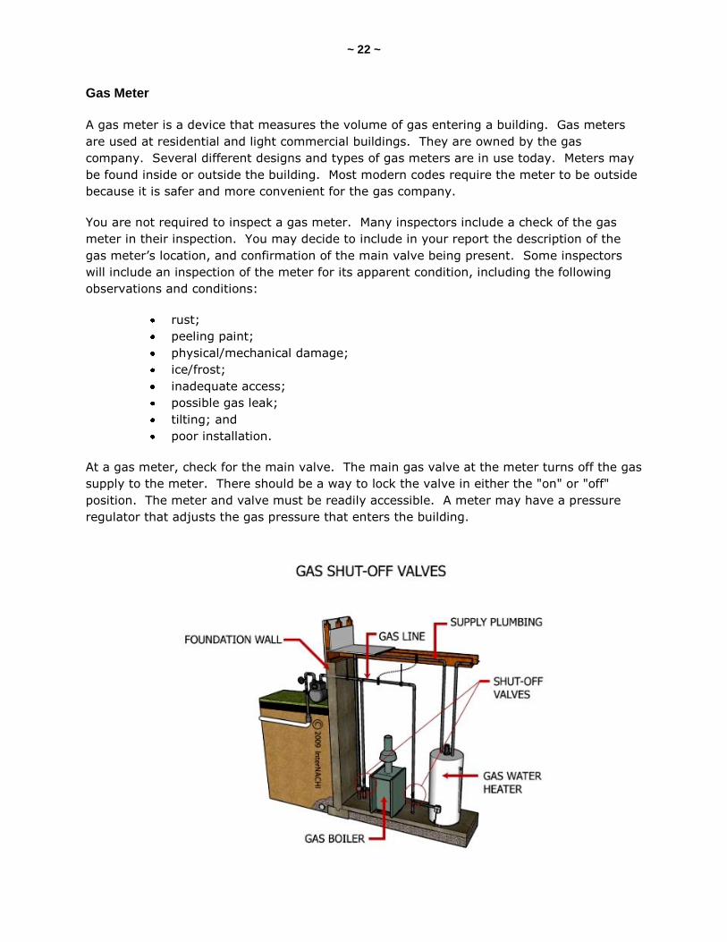
At a gas meter, check for the main valve. The main gas valve at the meter turns off the gas
supply to the meter. There should be a way to lock the valve in either the "on" or "off"
position. The meter and valve must be readily accessible. A meter may have a pressure
regulator that adjusts the gas pressure that enters the building.
~ 23 ~
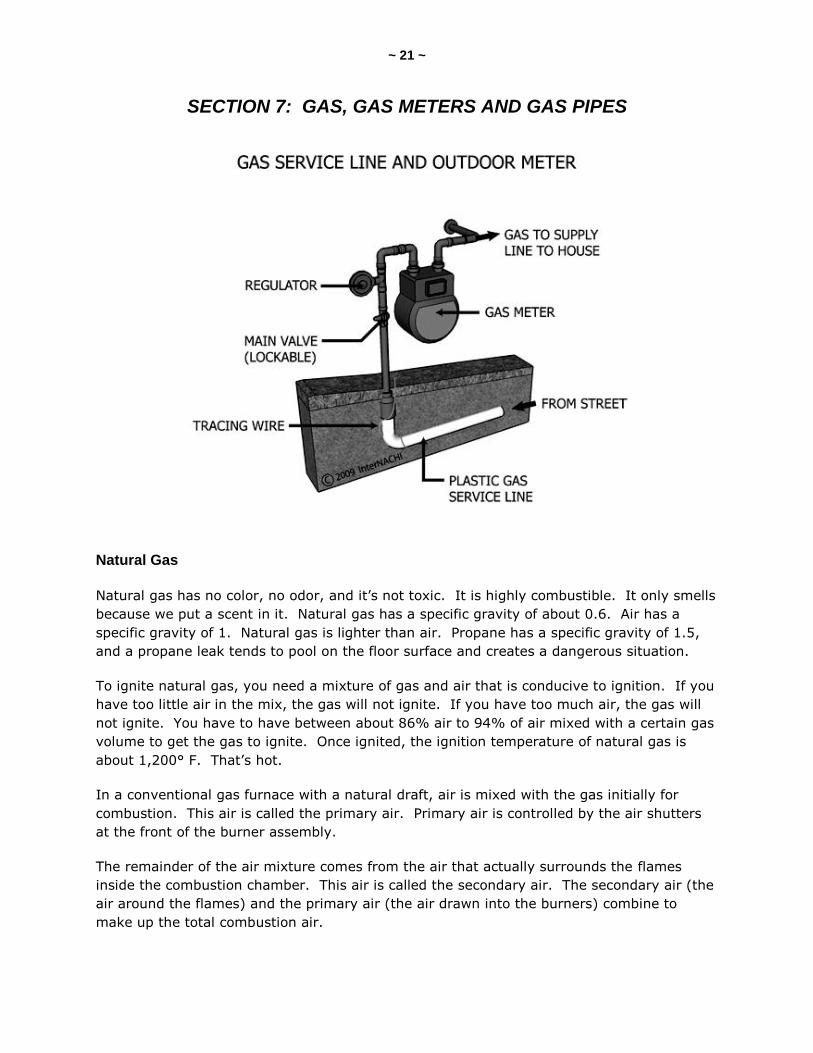
The gas service line from the street to the gas meter might be plastic. The plastic gas
service line should be around 15 inches below ground level, but this may vary, depending
on your jurisdiction. You should not see the plastic gas service line above the ground's
surface. You may see a pipe (a metal riser) coming out of the ground and connecting to the
gas meter. You may see a small wire wrapped around the service line that comes out of the
ground next to the meter. This is called the tracer wire.
Rust on the gas meter is usually only a surface condition and not a major defect.
Look for gas meters that are located in areas where they could be damaged by impact. Gas
meters should not be installed in driveways, carports or parking areas without steel posts or
some other type of barrier installed to protect against impact.
If the gas is in the "off" position, it is likely that a plumber or the gas company has turned
the gas off. Gas could be shut off temporarily if there is an appliance inside the building
that has been flagged or red-tagged as being unsafe to operate. If the gas is turned off, do
not turn it on. You are not required to turn on and operate gas valves.
Gas meters covered with ice, frost or snow may simply be located under a roof edge that
drops snow and ice on top of the gas meter below. Gas meters should not be covered with
ice or snow. They should not be located directly below the drip line of a roof’s edge.
Gas meters should be readily accessible. You may find gas meters hidden under dense
vegetation, or located in undesirable areas, including under decks or porches. Some
building standards require that gas meters be installed with adequate clearance from
combustible materials, from sources of ignition, and from the drip line of a roof edge.
Most codes prevent meters from being installed in unvented locations and crawlspaces.
Gas Piping
The gas piping installed before the meter (and the meter itself) is usually the responsibility
of the gas company. The gas piping installed after the meter is usually the responsibility of
the homeowner.
The most common gas piping material is black iron. Copper, brass and stainless steel
tubing are also used. If the gas piping is copper, then it should be of Type K, L or GP.
Underground piping is usually Type K.
You may see corrugated stainless steel tubing (CSST). CSST was approved for residential
use in 1988 by the National Fuel Gas Code. It is a method of supplying natural gas to
fireplaces, furnaces, cook tops, clothes dryers, and any other gas appliance. However,
some jurisdictions do not permit its use.
~ 24 ~
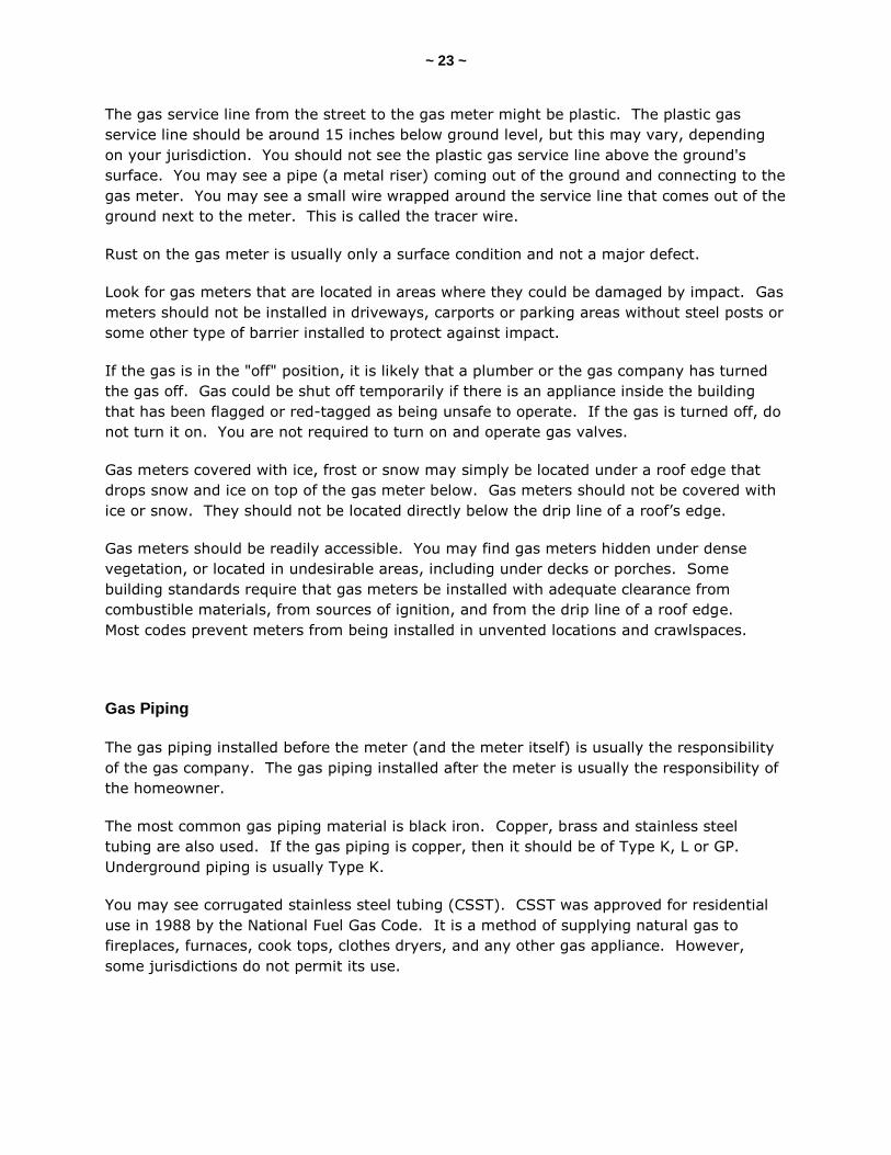
Most jurisdictions do not permit flexible gas pipes going through walls, floors or ceilings.
They cannot be concealed. They are limited in length. And the shut-off valve cannot be in
a different room than the appliance, unless it is clearly labeled. Gas pipes should not pass
through ducts.
~ 25 ~
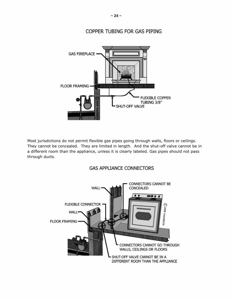
Teflon tape is not recommended. Pipe dope is preferred.
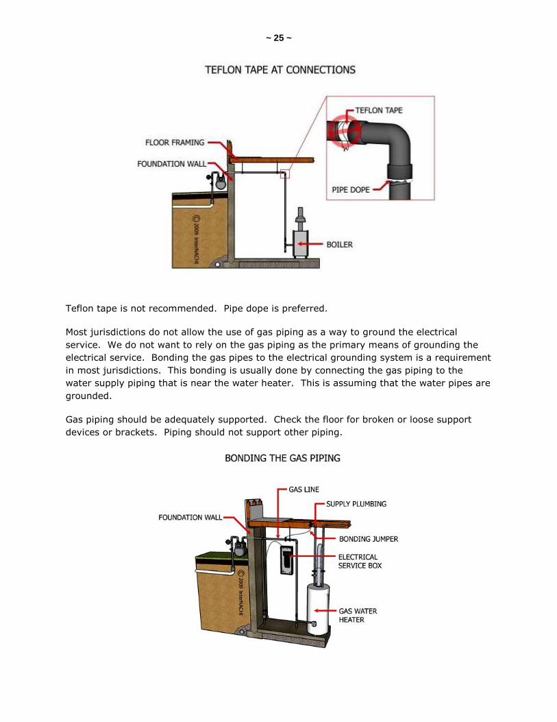
Most jurisdictions do not allow the use of gas piping as a way to ground the electrical
service. We do not want to rely on the gas piping as the primary means of grounding the
electrical service. Bonding the gas pipes to the electrical grounding system is a requirement
in most jurisdictions. This bonding is usually done by connecting the gas piping to the
water supply piping that is near the water heater. This is assuming that the water pipes are
grounded.
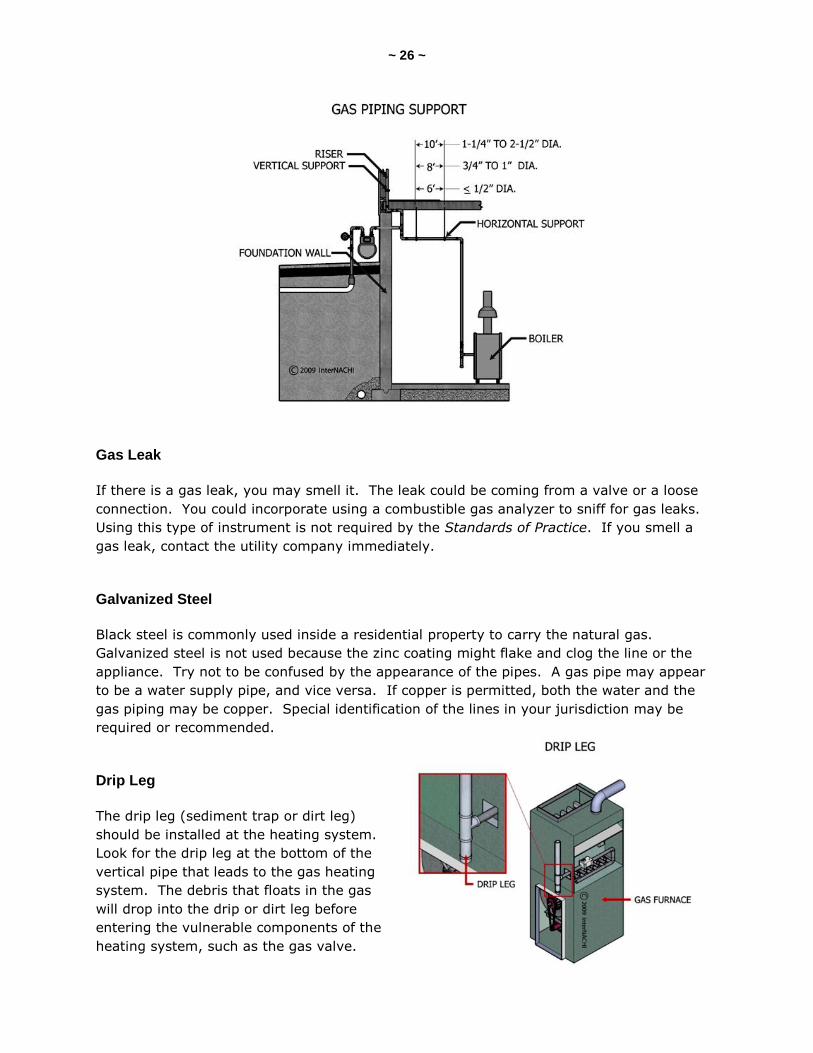
Gas piping should be adequately supported. Check the floor for broken or loose support
devices or brackets. Piping should not support other piping.
~ 26 ~
Gas Leak
If there is a gas leak, you may smell it. The leak could be coming from a valve or a loose
connection. You could incorporate using a combustible gas analyzer to sniff for gas leaks.
Using this type of instrument is not required by the Standards of Practice. If you smell a
gas leak, contact the utility company immediately.
Galvanized Steel
Black steel is commonly used inside a residential property to carry the natural gas.
Galvanized steel is not used because the zinc coating might flake and clog the line or the
appliance. Try not to be confused by the appearance of the pipes. A gas pipe may appear
to be a water supply pipe, and vice versa. If copper is permitted, both the water and the
gas piping may be copper. Special identification of the lines in your jurisdiction may be
required or recommended.
Drip Leg
The drip leg (sediment trap or dirt leg)
should be installed at the heating system.
Look for the drip leg at the bottom of the
vertical pipe that leads to the gas heating
system. The debris that floats in the gas
will drop into the drip or dirt leg before
entering the vulnerable components of the
heating system, such as the gas valve.
~ 27 ~
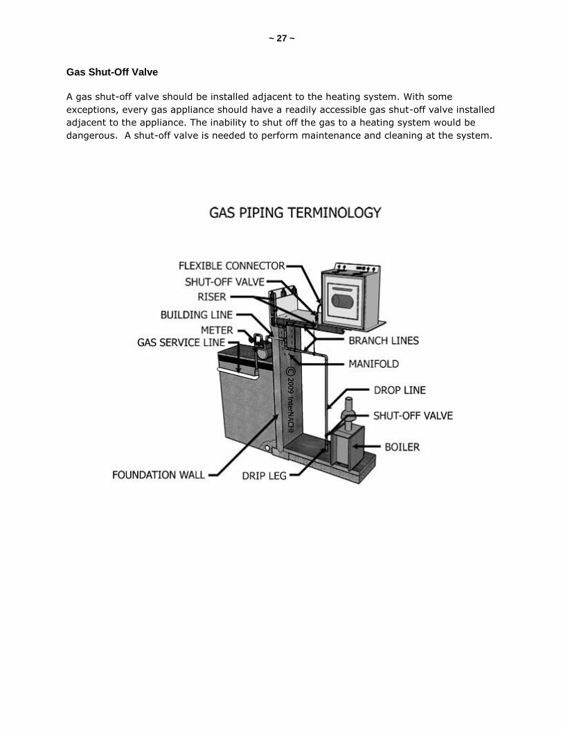
Gas Shut-Off Valve
A gas shut-off valve should be installed adjacent to the heating system. With some
exceptions, every gas appliance should have a readily accessible gas shut-off valve installed
adjacent to the appliance. The inability to shut off the gas to a heating system would be
dangerous. A shut-off valve is needed to perform maintenance and cleaning at the system.
~ 28 ~
SECTION 8: COMBUSTION FUNDAMENTALS
Combustion involves the burning of a fuel that produces heat energy. Combustion requires
adequate supply of air called combustion air. To have a successful combustion process,
there has to be a fuel, oxygen, and an ignition source.
Burning a natural gas can be explained by the general equation:
CH4 + 2O2 = CO2 + 2H2O+ heat.
Natural gas is about 85 to 90% methane (CH4). Burning natural gas (CH4) with oxygen
yields carbon dioxide (CO2) and water vapor (2H2O) and heat. This is referred to as
complete combustion.
In reality, air is the source of oxygen (O2), and in the air, oxygen is mixed with some
nitrogen. The resultant flue gas from the combustion will contain some nitrogen.
Combustion is never complete (or perfect). In combustion exhaust gases, both unburned
carbon (as soot) and carbon compounds (CO and others) will be present. Also, because air
is the oxidant, some nitrogen will be oxidized into various nitrogen oxides (NOX).
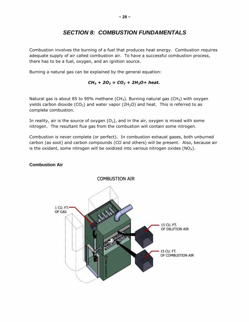
Combustion Air
~ 29 ~
Roughly 15 cubic feet of air is needed to burn 1 cubic foot of natural gas. Gas furnaces
need also draft air (or dilution air) to maintain a draft of the combustion gases. Another 15
cubic feet of air is needed for every cubic foot of natural gas. This air helps with a chimney
draft. Therefore, a conventional low-efficiency, standing-pilot gas furnace requires about 30
cubic feet of air (15 dilution plus 15 combustion) for every cubic foot of gas burned.
If combustion air is inadequately supplied to a gas furnace, carbon monoxide will likely be
produced. Carbon monoxide can be lethal.
Draft Types
There are three types of burners relative to the draft. They are:
natural-draft burners;
induced-draft burners; and
forced-draft burners.
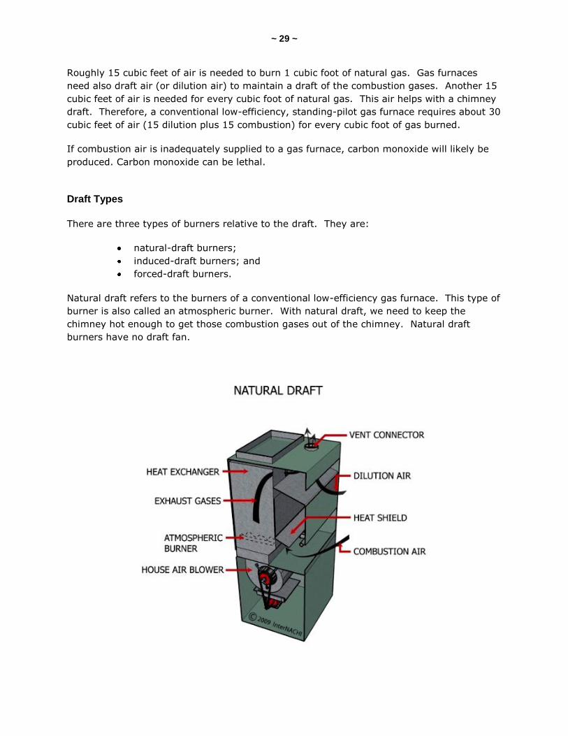
Natural draft refers to the burners of a conventional low-efficiency gas furnace. This type of
burner is also called an atmospheric burner. With natural draft, we need to keep the
chimney hot enough to get those combustion gases out of the chimney. Natural draft
burners have no draft fan.
~ 30 ~
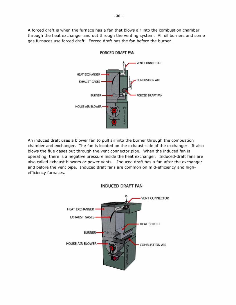
A forced draft is when the furnace has a fan that blows air into the combustion chamber
through the heat exchanger and out through the venting system. All oil burners and some
gas furnaces use forced draft. Forced draft has the fan before the burner.
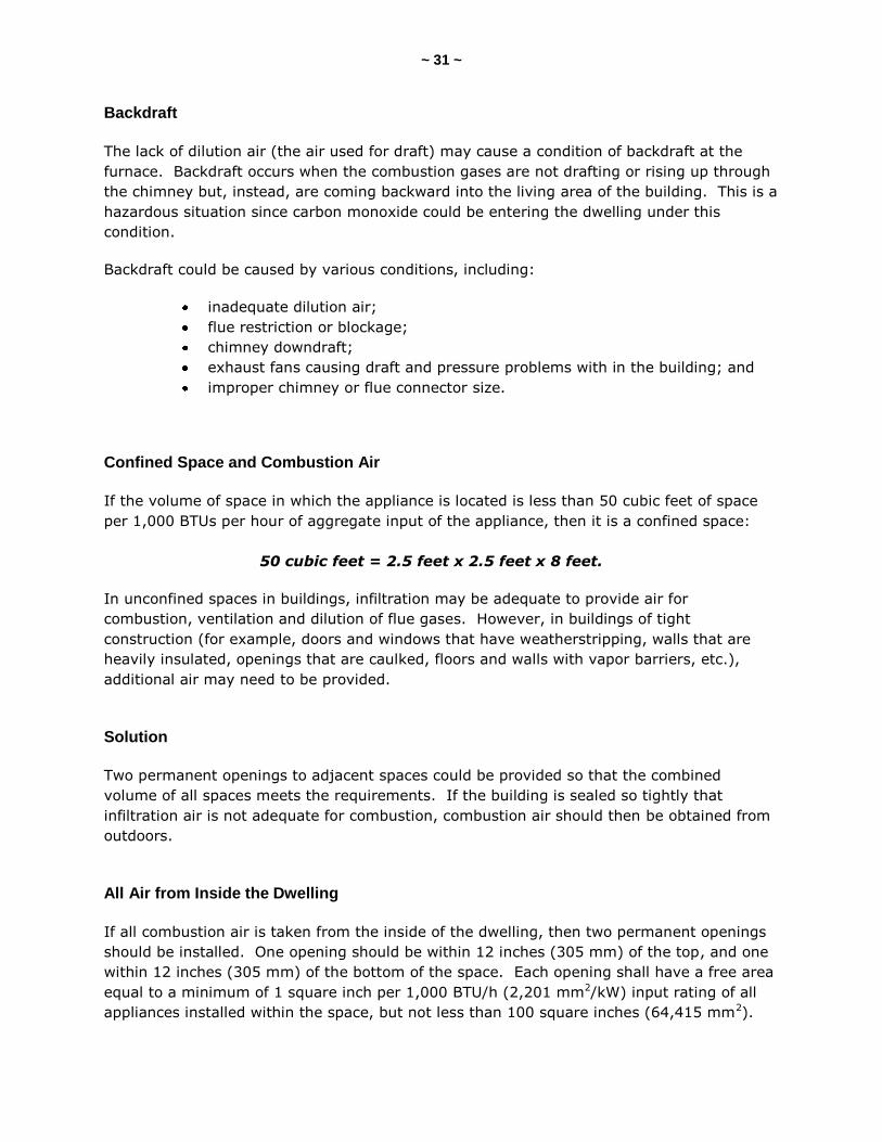
An induced draft uses a blower fan to pull air into the burner through the combustion
chamber and exchanger. The fan is located on the exhaust-side of the exchanger. It also
blows the flue gases out through the vent connector pipe. When the induced fan is
operating, there is a negative pressure inside the heat exchanger. Induced-draft fans are
also called exhaust blowers or power vents. Induced draft has a fan after the exchanger
and before the vent pipe. Induced draft fans are common on mid-efficiency and high-
efficiency furnaces.
~ 31 ~
Backdraft
The lack of dilution air (the air used for draft) may cause a condition of backdraft at the
furnace. Backdraft occurs when the combustion gases are not drafting or rising up through
the chimney but, instead, are coming backward into the living area of the building. This is a
hazardous situation since carbon monoxide could be entering the dwelling under this
condition.
Backdraft could be caused by various conditions, including:
inadequate dilution air;
flue restriction or blockage;
chimney downdraft;
exhaust fans causing draft and pressure problems with in the building; and
improper chimney or flue connector size.
Confined Space and Combustion Air
If the volume of space in which the appliance is located is less than 50 cubic feet of space
per 1,000 BTUs per hour of aggregate input of the appliance, then it is a confined space:
50 cubic feet = 2.5 feet x 2.5 feet x 8 feet.
In unconfined spaces in buildings, infiltration may be adequate to provide air for
combustion, ventilation and dilution of flue gases. However, in buildings of tight
construction (for example, doors and windows that have weatherstripping, walls that are
heavily insulated, openings that are caulked, floors and walls with vapor barriers, etc.),
additional air may need to be provided.
Solution
Two permanent openings to adjacent spaces could be provided so that the combined
volume of all spaces meets the requirements. If the building is sealed so tightly that
infiltration air is not adequate for combustion, combustion air should then be obtained from
outdoors.
All Air from Inside the Dwelling
If all combustion air is taken from the inside of the dwelling, then two permanent openings
should be installed. One opening should be within 12 inches (305 mm) of the top, and one
within 12 inches (305 mm) of the bottom of the space. Each opening shall have a free area
equal to a minimum of 1 square inch per 1,000 BTU/h (2,201 mm2/kW) input rating of all
appliances installed within the space, but not less than 100 square inches (64,415 mm2).
~ 32 ~
All Air from Outdoors
If all combustion air is taken from the outdoor air, then one opening should be within 12
inches of the top and one within 12 inches of the bottom of the space. The openings are
permitted to connect to spaces directly communicating with the outdoor air, such as a
ventilated crawlspace or ventilated attic space. Each opening should have a free area of at
least 1 square inch per 4,000 BTU/per hour (550 mm2/kW) of total input rating of all
appliances in the space when using vertical ducts (2,000 BTU/per hour if using horizontal
ducts).
Louvers
In calculating the free area of combustion air openings fitted with louvers, metal louvers
obstruct about 25% of the opening. Wooden louvers obstruct 75%.
~ 33 ~
SECTION 9: FURNACE FUNDAMENTALS
Part of the home inspection includes the inspection, identification and description of the
heating system.
In order to perform an inspection according to the Standards of Practice, an inspector must
apply the knowledge of what s/he understands about the different types of residential
heating systems. To fully inspect and identify a particular heating system, describe its
heating method, and identify any material defects observed, an inspector should be able to
explain and discuss with their client:
the heating system;
its heating method;
its type or identification;
how the heating system operates;
how to maintain it; and
the common problems that may be found.
The inspector must be able to thoroughly examine a heating system, understand how a
particular heating system operates, and analyze and draw conclusions as to its apparent
condition. An inspector should also be able to justify his/her observations, opinions and
recommendations that s/he has written in the inspection report.
Furnace
Let's focus on the fundamentals of a particular heating system called a furnace. There are
many ways to inspect, identify and describe the different types of furnaces that may be
found at a property using non-invasive, visual-only inspection techniques. It is up to the
inspector’s judgment as to how detailed the inspection and report will be. For example, the
inspector is not required to determine the capacity or BTU of the inspected heating system,
but many inspectors record that detailed information in their reports.
The American Society of Heating, Refrigerating and Air-Conditioning Engineers (ASHRAE)
defines a furnace as a “complete heating unit for transferring heat from fuel being burned to
the air supplied to a heating system.” Another definition of a furnace is “a self-enclosed,
fuel-burning unit for heating air by transfer of combustion through metal directly to the
air.” Taking these two definitions into consideration, there are two basic characteristics of a
furnace:
there is a fuel used to produce combustion; and
heat is transferred to the interior air.
Note that air –- not water or steam -– is used as the medium to convey the heat. This
characteristic distinguishes warm-air heating systems from other types of heating systems.
~ 34 ~
Let’s look at identifying and describing some warm-air heating systems known as furnaces.
Most modern furnaces are commonly referred to as central heating systems. The furnace is
often centralized within the structure. The furnace is used as the main, central warm-air
heating system. The heat of the furnace is forced (or rises) through a system of ducts or
pipes to other areas and rooms in the structure. The furnace does not necessarily need to
be centrally located within the structure if the furnace is a forced warm-air system.
Furnaces that have no distribution ducts or pipes are used in some heating applications.
They are limited in the size of the area that they can heat. They are installed within the
room or area to be heated and have no way to distribute the heat to other places.
Identification and Description of Furnaces
There are several ways to identify and describe a furnace using non-invasive, visual-only
inspection techniques, as required by the InterNACHI Standards of Practice. Furnaces can
be identified and described by:
fuel type;
distribution;
air flow;
gravity or forced;
efficiency; and
ignition.
Fuel Type
One way to identify and describe a furnace is based on the type of fuel used to produce
heat. Based on fuel type, one can classify a furnace as:
gas-fired;
oil-fired;
coal;
wood;
multi-fuel; or
electric.
Fossil fuels are used to produce combustion in the first five types. The last one uses
electricity. Whether or not electricity can be considered a fuel is not important here, since
an electric furnace functions in the same manner as the fossil-burning furnaces. The
electric furnace heats air and distributes it. According to the Standards, an inspector is
required to describe the energy source in their report.

~ 35 ~
Distribution
The inspector is also required to describe the heating method. One way to do that is to
identify the method of how the air is distributed throughout the house. Furnaces can be
identified and described or classified by the way the air is distributed. There are two broad
categories:
gravity warm-air furnaces; and
forced warm-air furnaces.
The gravity warm-air furnaces rely primarily on gravity for circulating the heated air. Warm
air is lighter than cool air and will rise and move through ducts and pipes. After releasing
its heat, the air becomes cooler and heavier. The air drops down the structure through
return registers to the furnace where it is heated again, and the cycle continues. The very
earliest types of furnaces were gravity-type furnaces. Sometimes, they had a blower fan
installed to move the heated air. They have mostly been replaced by modern, forced warm-
air furnaces.
Air Flow
Forced warm-air furnaces can be identified and described by how the air flows through the
heating unit in relation to the warm-air outlet and the return-air inlet locations on the
furnace. There are three types of forced warm-air furnaces related to air flow:
upflow (highboy or lowboy);
downflow; and
horizontal.
Furnace manufacturers commonly use the terms "upflow," "downflow" and "horizontal" in
their literature that describes their products, including their marketing materials, and
in their installation and operation manuals.
~ 36 ~
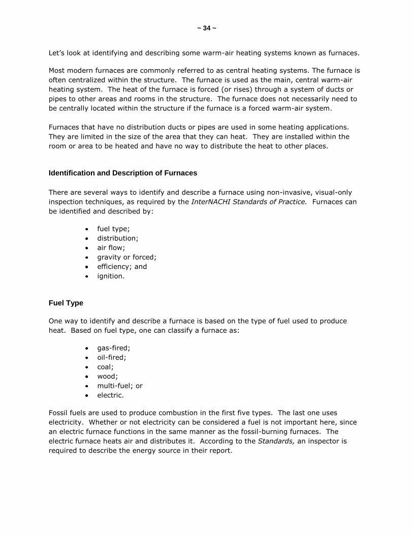
Upflow Highboy
On a typical upflow highboy furnace, the warm-air outlet is located at the top of the furnace,
so warm air discharges out of the top. The return-air inlet is located at the bottom or sides
of the furnace. A cooling unit is often added to the top of an upflow furnace. A typical
upflow highboy furnace stands no higher than 6 feet and can occupy a floor space of 6
square feet (2 feet x 3 feet).
Upflow Lowboy
An upflow lowboy furnace is designed for low clearances. Both the warm-air outlet and
return-air inlet are located at the top of the furnace. The lowboy is often installed in a
basement where most of the ductwork is above the heating unit. This compact heating unit
typically stands no higher than 4 feet. It is usually longer from front to back than either the
upflow highboy or downflow furnaces.
~ 37 ~
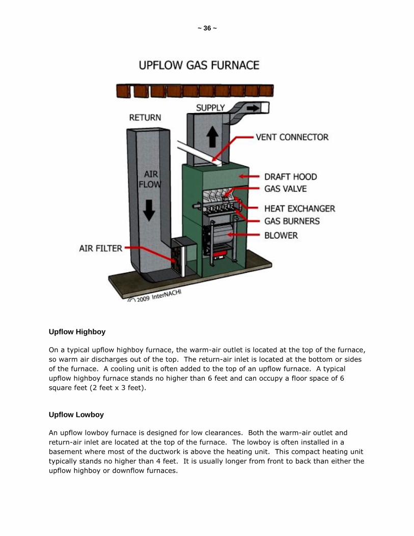
Downflow
A downflow furnace is also referred to as a counterflow furnace or a down-draft
furnace. Warm air discharges out of the bottom of a downflow furnace, and the return-air
inlet is located at the top. The downflow furnace is installed usually when most of the duct
or pipe distribution system is below the furnace. The ducts might be embedded in a
concrete floor slab or suspended in a crawlspace below the heating unit. The downflow
furnace is similar in dimension to the upflow, but the warm-air outlet is located at the
bottom instead of the top.
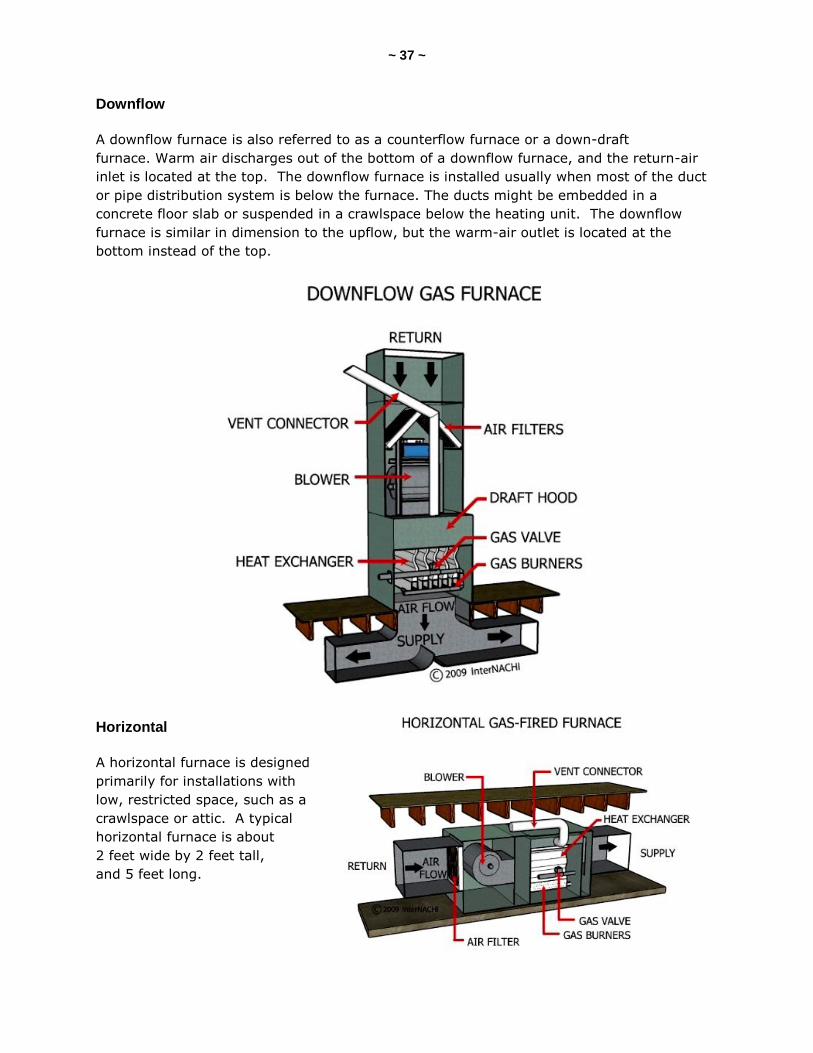
Horizontal
A horizontal furnace is designed
primarily for installations with
low, restricted space, such as a
crawlspace or attic. A typical
horizontal furnace is about
2 feet wide by 2 feet tall,
and 5 feet long.
~ 38 ~
Gravity Warm-Air Furnace
A gravity warm-air furnace uses the facts that warm air is lighter than cool air, and warm
air rises. In a gravity warm-air furnace, warm air might rise through ducts or pipes. After
releasing its heat, the air becomes cooler and heavier. The air drops down the structure
through return registers to the furnace, where it is heated again. The air is circulated
through the house in this manner.
The very earliest types of furnaces were gravity warm-air furnaces. They were popular from
the first half of the 19th century to the early 1970s. Sometimes, they had a blower fan
installed to move the heated air. But the primary way the air moved through the house
relied on how gravity affected the different weights of warm and cool air. Gravity warm-air
furnaces were sometimes described as "octopus" furnaces because of their appearance, with
all of the pipes coming out of the centrally located heating unit. Most of these gravity
furnaces are obsolete and at the end of their life expectancy.
A gravity warm-air furnace can be described in one of the following three ways:
a gravity warm-air furnace without a fan;
a gravity warm-air furnace with an integral fan; or
a gravity warm-air furnace with a booster fan.
A gravity warm-air furnace without a fan relies entirely on gravity and the different weights
of air to circulate the air through the house. The air-flow rate is slow. The air circulation
and distribution of heated air is not efficient. It is all but impossible to effectively control
the heat supplied to individual rooms of the house. Sometimes, an integral fan is installed
in the distribution ducts or pipes to reduce the internal resistance to air flow and increase
air movement.
A booster fan is installed to do the same, but does not interfere with air circulation when it
is not in use. A booster fan might be a belt-driven fan unit, resting on the floor and
attached to the outside of the heating unit.
Floor and space heaters operate using the same principles of gravity and air weights, as do
the gravity warm-air furnaces. They differ by the way a floor or space heater is designed to
provide heated air to a particular room or space, and do not distribute air throughout the
house.
Warm Air Rises
When a certain amount of air is heated up, it expands and takes up more space. In other
words, hot air is less dense than cold air. Any substance that is less dense than the fluid
(gas or liquid) of its surroundings will float. Hot air floats on cold air because it is less
dense, just as a piece of wood floats because it is less dense than water. Warm air is often
described as weighing less than cool air.

~ 39 ~
Pipeless Floor and Wall Furnaces
A pipeless floor furnace is a gravity warm-air heating system that is installed directly
beneath a floor. One large grille is installed for the warm air to rise up through. A cool-air
return is installed for air circulation. This type of furnace is sometimes considered a
permanently installed room heater. A wall furnace is installed in the wall and is also
considered a permanently installed room heater. Some of these units have blower fans, but
most operate on the principle of gravity for air circulation.
A common wall furnace is the type that is installed on the wall, in a closet or in a wall
recess. Wall furnaces are often gas- or oil-fired vertical units. There are upflow and
downflow wall furnaces with grilles at the bottom and top of the vertical unit.
Furnace Maintenance
Many property inspectors look for and report on indications of delayed maintenance.
Furnace maintenance is a very important part of the efficient operation of a warm-air
heating system. Furnace maintenance should never be neglected. The furnace
manufacturer will provide recommendations for proper maintenance in their installation and
operation manuals. With proper maintenance, the life of the furnace will be extended, its
efficiency will improve, and the costs to operate the furnace will be reduced. Maintaining a
furnace includes the cleaning and replacement of the air filter on a regular basis. Furnaces
should be periodically serviced by a technician. A maintenance schedule should be used and
should be posted near the furnace. The maintenance schedule should have dates,
maintenance comments, descriptions of repairs performed, and contact information for the
local technician who works on the furnace.
~ 40 ~
QUIZ 4
1. Burning natural gas with oxygen yields carbon dioxide, water vapor, and ________.
refrigerant
heat
cooling
2. T/F: A natural draft unit has a draft fan.
True
False
3. There are two broad categories to describe furnace heating systems: gravity warm-air furnaces; and ______ warm-air furnaces.
natural
forced
convective
4. A _______ furnace is also referred to as a counterflow furnace or a down-draft furnace.
upflow
downflow
horizontal
Answer Key to Quiz 4
1. Burning natural gas with oxygen yields carbon dioxide, water vapor, and heat.
2. T/F: A natural draft unit has a draft fan. Answer: False
3. There are two broad categories to describe furnace heating systems: gravity warm-air furnaces; and forced warm-air furnaces.
4. A downflow furnace is also referred to as a counterflow furnace or a down-draft furnace.

~ 41 ~
SECTION 10: WARM-AIR HEATING SYSTEMS
Warm-air heating systems use air as the heat-conveying medium that carries heat from the
heating system to the rooms and spaces of the dwelling. Air as the heat-conveying medium
is the distinguishing characteristic used by inspectors to identify and describe a particular
heating system. The warm-air heating system is usually (but not always) centrally located
in the structure. Any of the following fuels can be used in a warm-air heating system:
fuel oil (No. 2);
natural gas;
propane;
coal;
electricity;
wood;
kerosene; and
pellets.
The simple description of a warm-air heating system is as follows:
1. Cool air enters the furnace.
2. The furnace heats the air.
3. The warm air begins to rise.
4. The air is distributed either by simply rising up through the house (as in a gravity
warm-air furnace), or by a fan through ducts or pipes (as in a forced warm-air
furnace).
5. The warm air gives off its heat, gets cooler and heavier, and returns to the furnace
where it is re-heated.
A warm-air heating system is one in which air is heated by a furnace and then distributed to
the rest of the structure by the use of gravity or by a centrifugal fan. If gravity is
employed, then the warm-air heating system is referred to as a "gravity warm-air heating
system." If the movement of air primarily relies on a fan or some mechanical means for
circulation, then the warm-air heating system is referred to as a "forced warm-air heating
system." Remember:
gravity used = gravity warm-air heating system; and
fan used = forced warm-air heating system.
~ 42 ~
Now, don’t get confused. Some gravity warm-air systems use fans to assist in air
movement and circulation, and one system may be mistaken for the other when attempting
to describe it. One of the easiest ways for inspectors to identify and describe a particular
heating system is based on how the air is circulated -- by gravity or by a fan.
Gravity Warm-Air Heating Systems
A gravity warm-air heating system is a furnace with a method of supplying warm air and
returning cool air, relying primarily on gravity to move the air. The system consists of a
furnace and some ducts or pipes. Warm air rises, and cool air falls. The weight per unit-
volume of air decreases as its temperature increases. And, conversely, the weight per unit-
volume of air increases as its temperature decreases.
The furnace heats the air, and the air gets lighter and rises out of the heating system. Cool
air enters the heating system and pushes or displaces the warm, rising air. The warm air
rises up through warm-air ducts or pipes (often called stacks) that are inside the walls. The
warm air rises up through the building. The warm air enters a room through the supply
registers on the wall or floor. The cool air falls out of the room and might return through a
return grille, and travels back through return ducts to the heating system. Some houses
with old gravity heating systems may not have a lot of ducts and pipes, but might rely on
large openings covered with iron grates or grilles in the floors that allow the cool air to fall
down through the building. The cool air is allowed to simply fall back to the furnace –-
hence, the name "gravity warm-air heating system."
The air circulation in a house with a gravity warm-air heating system will depend on the
temperature difference between the warm air rising and the cool air falling. The greater the
temperature difference, the greater the speed that the air will circulate. Also, air circulation
in a gravity warm-air heating system is greatly affected by air filtering. An air filter can
resist and almost block the air flow in a gravity system. You may find that an integral fan
has been installed to overcome resistance to air flow.
Forced Warm-Air Heating Systems
A forced warm-air heating system consists of a furnace, a blower fan, controls, a duct
distribution system, and supply and return registers. The heating system warms the air,
and the air is forced through ducts or pipes into rooms throughout the building. The cool air
returns through the ducts back to the furnace where it is re-heated. And the cycle begins
again.
Some large homes have balancing problems. Certain rooms will feel colder than the rest of
the house. This problem can be solved in a few ways. One is by dividing the heating
system into two separate zones with each controlled by its own thermostat. You may find a
motorized damper installed in the duct system that is controlled by a thermostat. Zoning
equipment can be expensive. Usually, a system can be balanced manually by adjusting the
supply dampers installed inside the main supply ducts, and by using the dampers at the
warm-air outlets (lever-controlled dampers, floor diffusers, or registers).
~ 43 ~
Warm-Air Furnace
Most modern furnaces are commonly referred to as central heating systems. The furnace is
often centralized within the structure. The furnace is used as the main, central warm-air
heating system. The heat of the furnace is forced or rises through a system of ducts or
pipes to other areas and rooms in the structure. The furnace does not necessarily need to
be centrally located within the structure if the furnace is a forced warm-air system.
Furnaces that have no distribution ducts or pipes are used in some heating applications.
They are limited in the size of the area that they can heat. They are installed within the
room or area to be heated and have no way to distribute the heat to other places.
Identification and Description of Furnaces
There are several ways to identify and describe a furnace using non-invasive, visual-only
inspection techniques, as required by the InterNACHI Standards of Practice. Furnaces can
be identified and described by:
fuel type;
distribution;
air flow;
gravity or forced;
efficiency; and
ignition.
Fuel Type
One way to identify and describe a furnace is based on the type of fuel used to produce
heat. Based on fuel type, one can classify a furnace as:
gas-fired;
oil-fired;
coal;
wood;
multi-fuel; or
electric.
Fossil fuels are used to produce combustion in the first five types. The last one uses
electricity. Whether or not electricity can be considered a fuel is not important here, since
an electric furnace functions in the same manner as the other fossil-burning furnaces. The
electric furnace heats air and distributes it. According to the Standards, an inspector is
required to describe the energy source in the report.
~ 44 ~
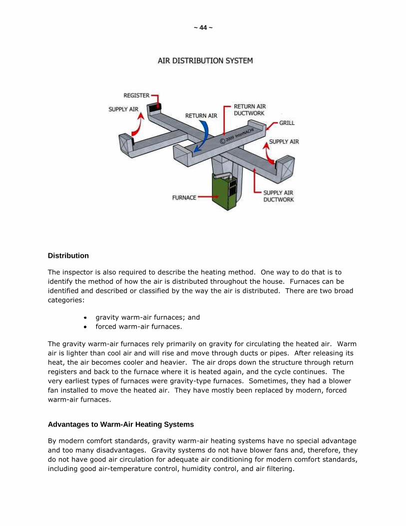
Distribution
The inspector is also required to describe the heating method. One way to do that is to
identify the method of how the air is distributed throughout the house. Furnaces can be
identified and described or classified by the way the air is distributed. There are two broad
categories:
gravity warm-air furnaces; and
forced warm-air furnaces.
The gravity warm-air furnaces rely primarily on gravity for circulating the heated air. Warm
air is lighter than cool air and will rise and move through ducts or pipes. After releasing its
heat, the air becomes cooler and heavier. The air drops down the structure through return
registers and back to the furnace where it is heated again, and the cycle continues. The
very earliest types of furnaces were gravity-type furnaces. Sometimes, they had a blower
fan installed to move the heated air. They have mostly been replaced by modern, forced
warm-air furnaces.
Advantages to Warm-Air Heating Systems
By modern comfort standards, gravity warm-air heating systems have no special advantage
and too many disadvantages. Gravity systems do not have blower fans and, therefore, they
do not have good air circulation for adequate air conditioning for modern comfort standards,
including good air-temperature control, humidity control, and air filtering.

~ 45 ~
Advantages of a Warm-Air Heating System
It costs less to install
than a hot-water or
steam-heating system.
Heat is delivered to the
rooms relatively quickly.
Heat delivery can be
stopped quickly.
Air filtering is easy to
install.
Humidity can be easily
controlled.
Air cooling (or air
conditioning) can be
easily installed.
The heating system does
not have to be centrally located.
Disadvantages of Warm-Air Heating Systems
There are a few
disadvantages to
warm-air heating
systems. For gravity
warm-air systems, the
heating system has to
be centrally located at
the lowest level of the
structure. Gravity
systems are slow to
respond, air movement
is slow, and air filtering
is restricted.
Forced warm-air heating systems require blower fans. They sometimes make noise. The
air movement may cause indoor air-quality issues because the air agitates dust and other
particles. Cool-air return inlets and warm-air supply registers must not be blocked, which
sometimes interferes with positioning furniture, and has some architectural design
demands. Warm air is supplied in bursts of convection heat, which may cause room air
temperatures to vary.
~ 46 ~
SECTION 11: DUCTS
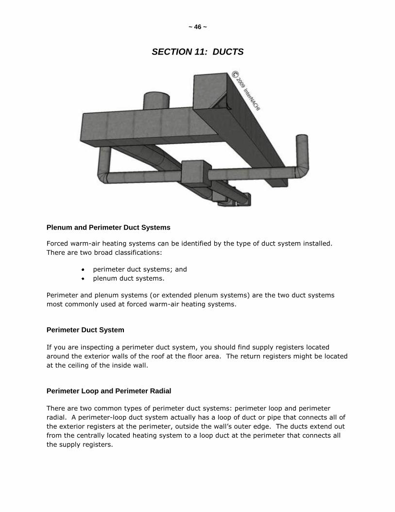
Plenum and Perimeter Duct Systems
Forced warm-air heating systems can be identified by the type of duct system installed.
There are two broad classifications:
perimeter duct systems; and
plenum duct systems.
Perimeter and plenum systems (or extended plenum systems) are the two duct systems
most commonly used at forced warm-air heating systems.
Perimeter Duct System
If you are inspecting a perimeter duct system, you should find supply registers located
around the exterior walls of the roof at the floor area. The return registers might be located
at the ceiling of the inside wall.
Perimeter Loop and Perimeter Radial
There are two common types of perimeter duct systems: perimeter loop and perimeter
radial. A perimeter-loop duct system actually has a loop of duct or pipe that connects all of
the exterior registers at the perimeter, outside the wall’s outer edge. The ducts extend out
from the centrally located heating system to a loop duct at the perimeter that connects all
the supply registers.

~ 47 ~
With a radial-perimeter duct system, the ducts radiate out from a centralized location,
where the heating system is installed, and extends outward to the exterior walls where the
supply registers are located. There is no loop duct at a radial perimeter system.
Perimeter-loop warm-air heating systems are often found in homes built on a concrete slab
rather than a basement. In this system, round ducts are embedded in the slab.
Plenum Duct System
If you are inspecting a plenum duct system, then you should find a large, rectangular duct
that comes directly out of the heating system and runs in a straight line down the center of
the basement, attic or ceiling. From the large, rectangular plenum extension, there will be
ducts branching out to all of the supply registers or heat-emitting units. The branching
ducts are usually round, located between floor joists, and often covered by a ceiling.
Plenum duct systems are often called extended plenum duct systems because the large
rectangular duct extends directly out of the supply outlet (or main plenum) of the heating
system -- hence, the name. The extended plenum duct system is very common for most
modern residential forced warm-air heating systems.
Duct Materials
Ducts can be made out of a variety of materials, including:
plain steel;
galvanized sheet metal;
aluminum;
copper;
fiberglass;
paper fiber; and
vitrified clay tile.
Plain steel and galvanized sheet-metal cuts are about 0.0163 to 0.1419 inches thick.
Aluminum and copper ducts are typically installed outside the building. Paper-fiber and clay
ducts are installed in concrete.

~ 48 ~
Duct Terms
In a forced warm-air heating system, the warm air comes out of the furnace in an area
called the furnace plenum or furnace hood. An extended plenum duct system will have
a large rectangular duct connected to this plenum and will extend out in a straight line. The
duct between the furnace and the plenum is often called the starting collar. Ducts that
carry warm air to a room are called supply ducts. Round or square supply ducts that are
connected to and branch off the extended duct are called side take-offs. These supply
branches are connected to register boots or elbows. Changes in direction of the ducts
are made by angle ducts. A large vertical duct or warm-air riser is sometimes called a
stack duct. A warm-air supply duct that runs horizontally from the furnace plenum to a
riser is called a leader. Dampers may be installed in ducts to control the amount of air
moving through the duct. Dampers can be manual or automatically controlled. All of the
ducts that carry cool air back to the furnace are called return ducts.
Dampers
A damper is a device used to vary the volume of air passing through a confined cross-
section by varying the cross-sectional area. In other words, a damper controls the air flow
inside a duct or pipe. It is a moveable obstruction. There are volume dampers, splitter
dampers, and squeeze dampers. Dampers can be manually and automatically controlled.

~ 49 ~
Grilles, Registers and Diffusers
There are three broad types of warm-air supply outlet devices: grilles; registers; and
diffusers.
Grilles deflect the air up, down, and side to side, depending on the direction in which the
louvers are pointed. Grilles are installed on high or low wall locations. Floor grilles are
commonly used in gravity warm-air systems. They could have movable louvers, but usually
do not.
A register is similar to a grille, but a register has a damper to control the air flow. They
can be on walls or floors.
Diffusers are typically formed in concentric cones or pyramids. They can be on walls and
are often on ceilings. Baseboard diffusers are used in perimeter forced warm-air heating
systems.
Returns
Cool-air returns should be located as far away from the supply outlets as possible. Returns
are typically located at the bottom of walls near the center of the building. Return grilles
should be kept away from the furnace. If the return grille is too close to a furnace, there
may be a draft problem created, causing backdraft or flame rollout conditions.
~ 50 ~
QUIZ 5
1. If you are inspecting a _______ duct system, you should find a large rectangular duct that comes directly out of the heating system and runs in a straight line down the center of the basement, attic or ceiling.
plenum
perimeter
loop
2. T/F: Round or square supply ducts that are connected to and branch off the extended duct are called side takeoffs.
True
False
3. T/F: Grilles are typically formed in concentric cones or pyramids.
True
False
Answer Key to Quiz 5
1. If you are inspecting a plenum duct system, you should find a large rectangular duct that comes directly out of the heating system and runs in a straight line down the center of the basement, attic or ceiling.
2. T/F: Round or square supply ducts that are connected to and branch off the extended duct are called side takeoffs. Answer: True
3. T/F: Grilles are typically formed in concentric cones or pyramids. Answer: False
~ 51 ~
SECTION 12: GAS FURNACES
There is a variety of ways to describe different types of residential gas furnaces. Gas
furnaces can be classified by:
the direction of the air flowing through the heating unit;
the heating efficiency of the unit; and
the type of ignition system installed on the unit.
Air Flow in Gas Furnaces
One way to identify and describe a gas furnace is by the direction of the air flowing through
the heating unit, or the location of the warm-air outlet and the return-air inlet on the
furnace. Gas furnaces can be described as upflow, downflow (counterflow), highboy,
lowboy, and horizontal flow. Air can flow up through the furnace (upflow), down through
the furnace (downflow), or across the furnace (horizontal). The arrangement of the furnace
should not significantly affect its operation, or your inspection.
BTU
Gas furnaces can be classified by their different capacities. A furnace capacity can be
described by BTU output. The BTU is determined by what is required by the heating unit for
the structure, which is the amount of heat the unit needs to produce in order to replace
heat loss and provide the occupants with a satisfactory comfort level.
AFUE
Furnaces can be identified and described by heating efficiency. The energy efficiency of a
natural gas furnace is measured by its annual fuel utilization efficiency (AFUE). The higher
the rating, the more efficient the furnace. The U.S. government has established a minimum
rating for furnaces of 78%. Mid-efficiency furnaces have AFUE ratings of between 78 to
82%. High-efficiency furnaces have AFUE ratings of 88 to 97%. Old, standing-pilot gas
furnaces have AFUE ratings of 60 to 65%. Gravity warm-air furnaces might have
efficiencies lower than 60%.
BTU and Efficiency
“BTU” stands for British thermal unit. The BTU is a unit of energy. It is approximately the
amount of energy needed to heat 1 pound of water to 1 degree Fahrenheit. One cubic foot
of natural gas contains about 1,000 BTUs. A gas furnace that fires at a rate of 100,000
BTUs per hour will burn about 100 cubic feet of gas every hour.
~ 52 ~
On a gas furnace, there should be a data plate. On that plate may be indicated the
furnace's input and output capacities. For example, the data plate may say, “Input 100,000
BTU per hour.” And it may also say, “Output 80,000 BTU per hour.” While this furnace is
running, about 20% of the heat generated is lost through the exhaust gases. The ratio of
the output to the input BTU is 80,000 ÷ 100,000 = 80% efficiency. This is the “steady-
state efficiency” of the furnace.
Steady-state efficiency measures how efficiently a furnace converts fuel to heat, once the
furnace has warmed up and is running steadily. However, furnaces cycle off and on as they
maintain their desired temperature. Furnaces typically don't operate as efficiently when
they start up and cool down. As a result, steady-state efficiency is not as reliable an
indicator of the overall efficiency of a furnace.
AFUE and Efficiency
The AFUE is the most widely used measure of a furnace's heating efficiency. It measures
the amount of heat delivered to your house compared to the amount of fuel that must be
supplied to the furnace. Thus, a furnace that has an 80% AFUE rating converts 80% of the
fuel that is supplied to heat. The other 20% is lost and wasted.
Note that the AFUE refers only to the unit's fuel efficiency and not its electricity usage. The
U.S. Department of Energy (DOE) determined that, as of 1992, all furnaces sold in the U.S.
must have a minimum AFUE of 78%. Mobile home furnaces are required to have a
minimum AFUE of 75%.
The DOE's definition of AFUE is the measure of seasonal or annual efficiency of a furnace or
boiler. It takes into account the cyclic on/off operation and associated energy losses of the
heating unit as it responds to changes in the load, which, in turn, are affected by changes in
the weather and occupant controls.
Ignition Type
Gas furnaces can be identified and described by the type of ignition system on the furnace.
The different types of ignition systems are:
standing-pilot;
intermittent-pilot or direct-spark; and
hot-surface ignition.
The older gas furnaces have a standing-pilot light that is always burning. Modern furnaces
with higher efficiency ratings are slowly replacing these older, conventional gas furnaces.
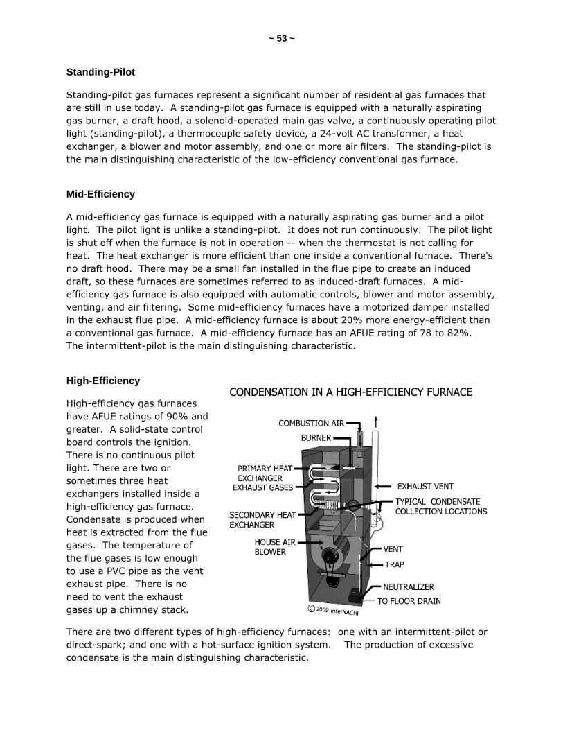
~ 53 ~
Standing-Pilot
Standing-pilot gas furnaces represent a significant number of residential gas furnaces that
are still in use today. A standing-pilot gas furnace is equipped with a naturally aspirating
gas burner, a draft hood, a solenoid-operated main gas valve, a continuously operating pilot
light (standing-pilot), a thermocouple safety device, a 24-volt AC transformer, a heat
exchanger, a blower and motor assembly, and one or more air filters. The standing-pilot is
the main distinguishing characteristic of the low-efficiency conventional gas furnace.
Mid-Efficiency
A mid-efficiency gas furnace is equipped with a naturally aspirating gas burner and a pilot
light. The pilot light is unlike a standing-pilot. It does not run continuously. The pilot light
is shut off when the furnace is not in operation -- when the thermostat is not calling for
heat. The heat exchanger is more efficient than one inside a conventional furnace. There's
no draft hood. There may be a small fan installed in the flue pipe to create an induced
draft, so these furnaces are sometimes referred to as induced-draft furnaces. A mid-
efficiency gas furnace is also equipped with automatic controls, blower and motor assembly,
venting, and air filtering. Some mid-efficiency furnaces have a motorized damper installed
in the exhaust flue pipe. A mid-efficiency furnace is about 20% more energy-efficient than
a conventional gas furnace. A mid-efficiency furnace has an AFUE rating of 78 to 82%.
The intermittent-pilot is the main distinguishing characteristic.
High-Efficiency
High-efficiency gas furnaces
have AFUE ratings of 90% and
greater. A solid-state control
board controls the ignition.
There is no continuous pilot
light. There are two or
sometimes three heat
exchangers installed inside a
high-efficiency gas furnace.
Condensate is produced when
heat is extracted from the flue
gases. The temperature of
the flue gases is low enough
to use a PVC pipe as the vent
exhaust pipe. There is no
need to vent the exhaust
gases up a chimney stack.
There are two different types of high-efficiency furnaces: one with an intermittent-pilot or
direct-spark; and one with a hot-surface ignition system. The production of excessive
condensate is the main distinguishing characteristic.
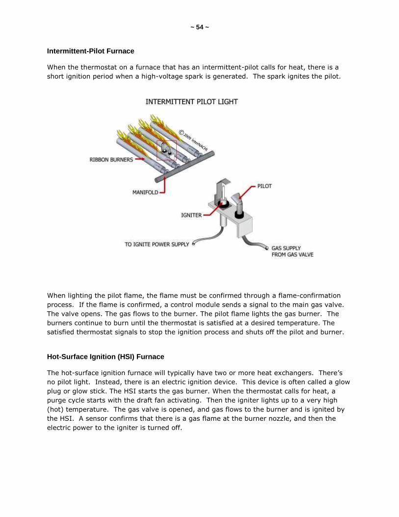
~ 54 ~
Intermittent-Pilot Furnace
When the thermostat on a furnace that has an intermittent-pilot calls for heat, there is a
short ignition period when a high-voltage spark is generated. The spark ignites the pilot.
When lighting the pilot flame, the flame must be confirmed through a flame-confirmation
process. If the flame is confirmed, a control module sends a signal to the main gas valve.
The valve opens. The gas flows to the burner. The pilot flame lights the gas burner. The
burners continue to burn until the thermostat is satisfied at a desired temperature. The
satisfied thermostat signals to stop the ignition process and shuts off the pilot and burner.
Hot-Surface Ignition (HSI) Furnace
The hot-surface ignition furnace will typically have two or more heat exchangers. There’s
no pilot light. Instead, there is an electric ignition device. This device is often called a glow
plug or glow stick. The HSI starts the gas burner. When the thermostat calls for heat, a
purge cycle starts with the draft fan activating. Then the igniter lights up to a very high
(hot) temperature. The gas valve is opened, and gas flows to the burner and is ignited by
the HSI. A sensor confirms that there is a gas flame at the burner nozzle, and then the
electric power to the igniter is turned off.
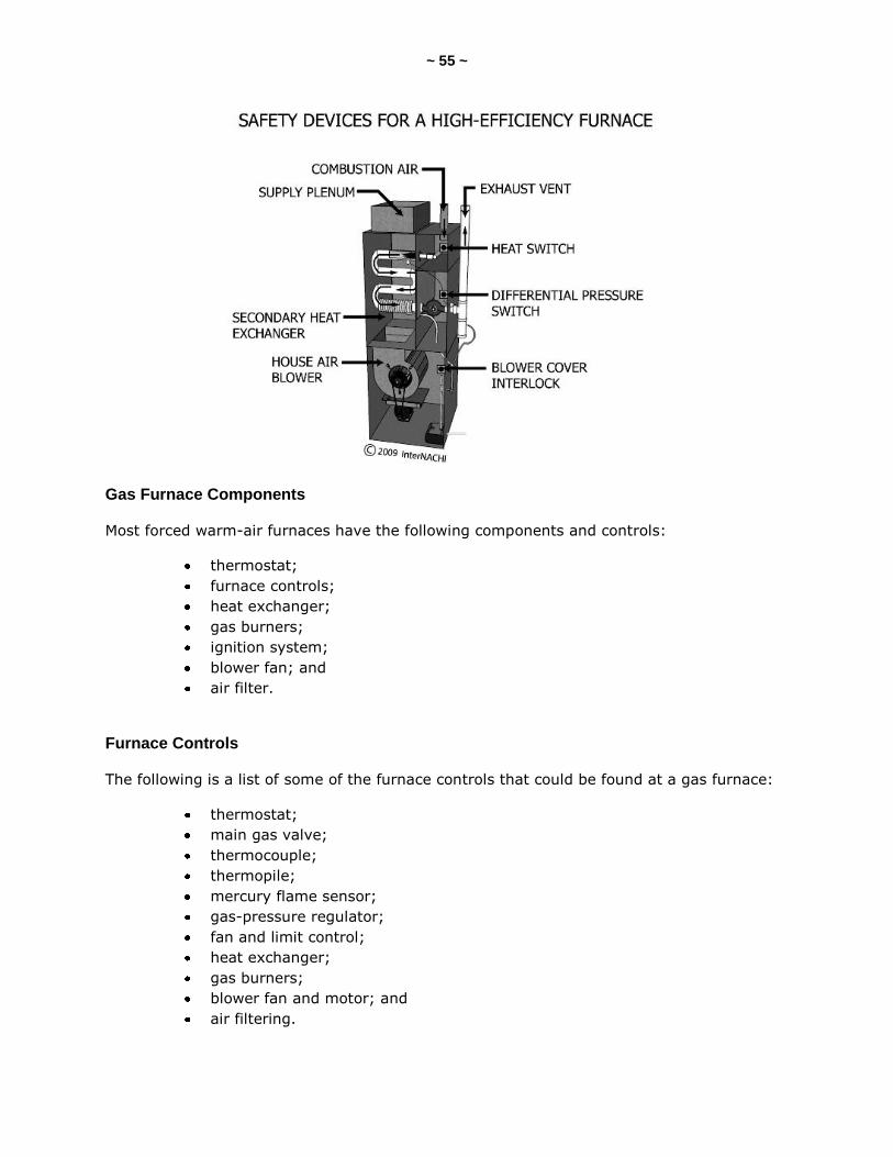
~ 55 ~
Gas Furnace Components
Most forced warm-air furnaces have the following components and controls:
thermostat;
furnace controls;
heat exchanger;
gas burners;
ignition system;
blower fan; and
air filter.
Furnace Controls
The following is a list of some of the furnace controls that could be found at a gas furnace:
thermostat;
main gas valve;
thermocouple;
thermopile;
mercury flame sensor;
gas-pressure regulator;
fan and limit control;
heat exchanger;
gas burners;
blower fan and motor; and
air filtering.
~ 56 ~
Thermostat
A thermostat controls the operation of the furnace. The thermostat senses the air
temperature in the room or space that is being heated. It sends signals to open and close
the main gas valve.
Heat Exchanger
The heat exchanger is a metal surface located in between the hot combustion gases and the
air that is circulating through the furnace. The hot combustion gases heat up the metal
material of the heat exchanger, and the heat is transferred from the hot metal to the air
passing through it. The warm air is forced through the ducts or pipes by a blower fan, and
distributed to the rooms or areas of the building.
Thermocouple
A thermocouple is a device that senses heat. A thermocouple is used in standing-pilot light
gas furnaces. It determines whether the pilot flame is lit before the main gas valve is
opened to supply gas to the burners. The flame must be lit before the valve is opened.
The heat of the pilot flame is converted to electricity by the thermocouple. It turns heat
into an electrical current. The current is strong enough to open the main gas valve. After
being opened, the gas flows to the pilot light. If the thermocouple does not detect a pilot
flame, it will turn off the gas supply to the pilot. The electrical current from a 24-volt AC
transformer operates the main gas valve.
Thermopile
Instead of a thermocouple, a thermopile is used in some standing-pilot gas furnaces. A
thermopile senses the heat from a pilot-light flame. It is larger than a thermocouple. It
operates both the main gas valve and the pilot light. When there is a thermopile, there’s
no transformer required.
Mercury-Flame Sensor
A mercury-flame sensor might be used in an electronic ignition system. It consists of a
sensor filled with mercury, a capillary tube, and a switch. The burner flame heats up the
sensor.
Gas-Pressure Regulator
The pressure regulator is installed on the main gas valve. It regulates the gas pressure,
ensuring a constant gas pressure in the burner manifold. For a propane gas heating system,
the regulator is located between the supply tank and the main gas valve.

~ 57 ~
Fan and Limit Control
The fan and limit control is a safety device. It is installed inside the furnace plenum where it
senses the air temperature that passes through that area. It controls the operation of the
furnace within a temperature range, usually between 80° F and 150° F. It prevents the
furnace from overheating by turning off the gas supply to the burner assembly. It can also
turn off the fan when the burner has been turned off and the temperature drops below the
lowest setting.
Heat Exchanger
The heat exchanger is made of steel. Sometimes, it is aluminum or galvanized. In hostile
environments, heat exchangers can be coated with a porcelain material to provide
protection against corrosive chemicals.
The flames come from the burner and go into an enclosure called a combustion chamber or
firebox. The heat exchanger is located directly above that. The heat from the combustion
process taking place is transferred to the metal walls of the heat exchanger. The heat is
transferred from the metal to the air that passes through the exchanger.
The heat exchanger can reach several hundred degrees in temperature. Air flowing across
the heat exchanger must be at a high speed and must be uniform across all sections of the
exchanger. If the air flow is low across one section, that section of the exchanger will
overheat and may cause a failure in the exchanger.
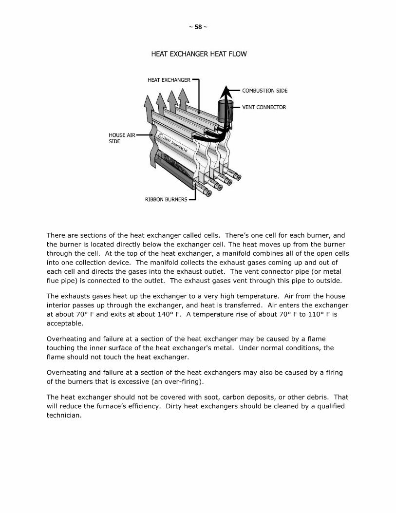
~ 58 ~
There are sections of the heat exchanger called cells. There’s one cell for each burner, and
the burner is located directly below the exchanger cell. The heat moves up from the burner
through the cell. At the top of the heat exchanger, a manifold combines all of the open cells
into one collection device. The manifold collects the exhaust gases coming up and out of
each cell and directs the gases into the exhaust outlet. The vent connector pipe (or metal
flue pipe) is connected to the outlet. The exhaust gases vent through this pipe to outside.
The exhausts gases heat up the exchanger to a very high temperature. Air from the house
interior passes up through the exchanger, and heat is transferred. Air enters the exchanger
at about 70° F and exits at about 140° F. A temperature rise of about 70° F to 110° F is
acceptable.
Overheating and failure at a section of the heat exchanger may be caused by a flame
touching the inner surface of the heat exchanger's metal. Under normal conditions, the
flame should not touch the heat exchanger.
Overheating and failure at a section of the heat exchangers may also be caused by a firing
of the burners that is excessive (an over-firing).
The heat exchanger should not be covered with soot, carbon deposits, or other debris. That
will reduce the furnace’s efficiency. Dirty heat exchangers should be cleaned by a qualified
technician.
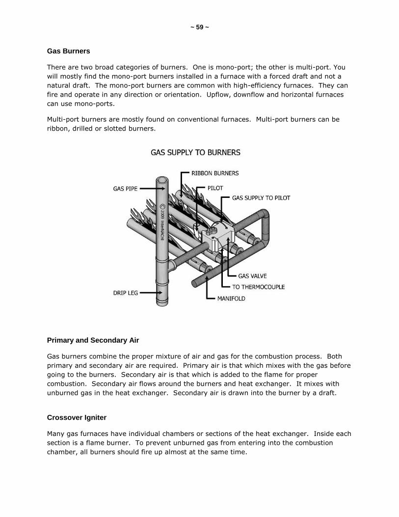
~ 59 ~
Gas Burners
There are two broad categories of burners. One is mono-port; the other is multi-port. You
will mostly find the mono-port burners installed in a furnace with a forced draft and not a
natural draft. The mono-port burners are common with high-efficiency furnaces. They can
fire and operate in any direction or orientation. Upflow, downflow and horizontal furnaces
can use mono-ports.
Multi-port burners are mostly found on conventional furnaces. Multi-port burners can be
ribbon, drilled or slotted burners.
Primary and Secondary Air
Gas burners combine the proper mixture of air and gas for the combustion process. Both
primary and secondary air are required. Primary air is that which mixes with the gas before
going to the burners. Secondary air is that which is added to the flame for proper
combustion. Secondary air flows around the burners and heat exchanger. It mixes with
unburned gas in the heat exchanger. Secondary air is drawn into the burner by a draft.
Crossover Igniter
Many gas furnaces have individual chambers or sections of the heat exchanger. Inside each
section is a flame burner. To prevent unburned gas from entering into the combustion
chamber, all burners should fire up almost at the same time.
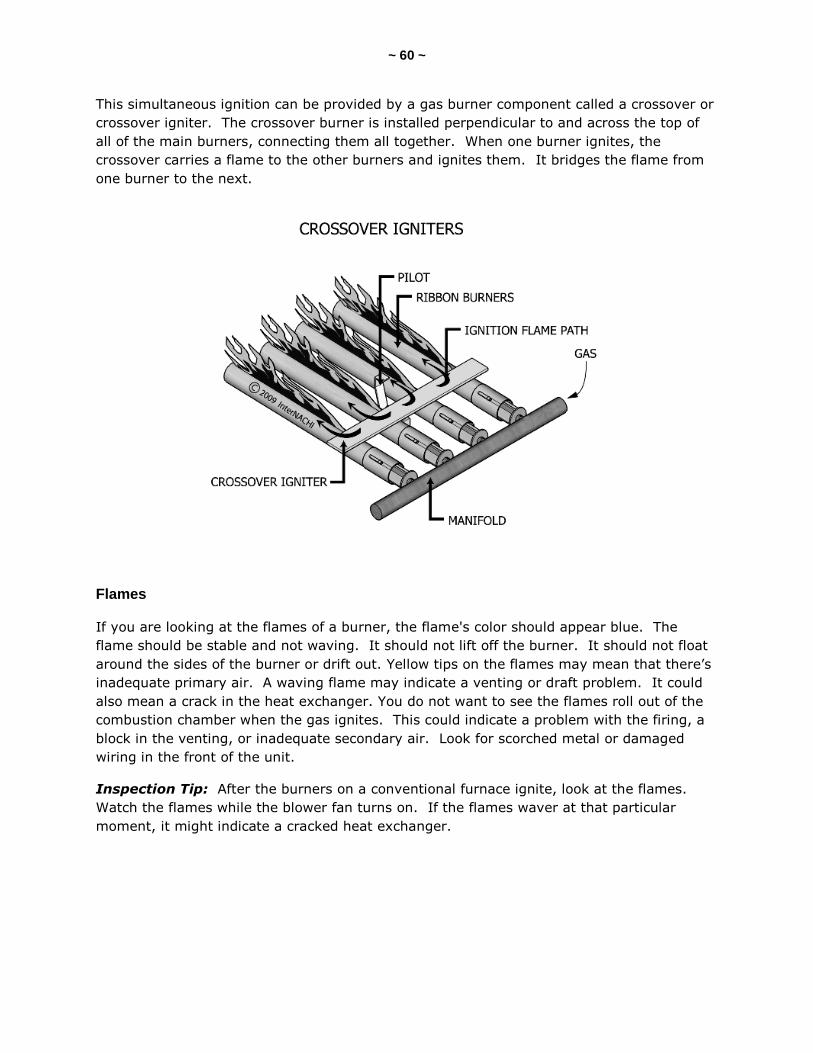
~ 60 ~
This simultaneous ignition can be provided by a gas burner component called a crossover or
crossover igniter. The crossover burner is installed perpendicular to and across the top of
all of the main burners, connecting them all together. When one burner ignites, the
crossover carries a flame to the other burners and ignites them. It bridges the flame from
one burner to the next.
Flames
If you are looking at the flames of a burner, the flame's color should appear blue. The
flame should be stable and not waving. It should not lift off the burner. It should not float
around the sides of the burner or drift out. Yellow tips on the flames may mean that there’s
inadequate primary air. A waving flame may indicate a venting or draft problem. It could
also mean a crack in the heat exchanger. You do not want to see the flames roll out of the
combustion chamber when the gas ignites. This could indicate a problem with the firing, a
block in the venting, or inadequate secondary air. Look for scorched metal or damaged
wiring in the front of the unit.
Inspection Tip: After the burners on a conventional furnace ignite, look at the flames.
Watch the flames while the blower fan turns on. If the flames waver at that particular
moment, it might indicate a cracked heat exchanger.
~ 61 ~
Blower Fan and Motor
Forced warm-air furnaces have blower fans installed. A blower fan has two functions:
it moves heated air through the distribution supply ducts or pipes; and
it protects the heat exchanger from overheating by blowing air across its
metal surfaces.
The air enters the furnace, gets heated, and is circulated throughout the building. Some
say that the fan draws in (or sucks) the air into the furnace. Others say that it blows air out
through the system. Whichever the case, the primary function of the blower fan is
circulation.
The fan motors are either belt-driven or direct-drive. Most modern furnaces have blower
fans with direct-drive motors. Direct-drive motors have various fan speeds than can be set
and adjusted by wiring. Belt-driven motors can be adjusted for various speeds by physically
adjusting the distance between the fixed flange and the movable pulley.
Modern blower fans have multiple speeds. A multi-speed fan operates at low speeds when
the furnace is off. This allows the air to move slowly and helps with air filtration and
humidification, for example, which works well at low speeds. The blower fan operates at
high speeds when the furnace is operating, or when the air-conditioning system is turned
on. When the air-conditioning system is on, the blower fan automatically turns on at a
higher speed.
Rust
There are many reasons that rust may be found on the burners. Rust on the burners may
be caused many things, including:
a condensate or water leak from above;
condensation in the flue running back into the combustion chamber; or
a clothes dryer venting into the furnace room.
Dirt and Soot
Dirt and soot on the burners could cause incomplete combustion and could make the
furnace work harder to heat the house. Dirty burners likely indicate delayed maintenance.
Air Filtering
All forced warm-air heating systems should have air filtering installed. There is a variety of
air filters available for furnaces. Many furnaces are equipped with a disposable air filter that
cleans the circulating air. There are washable air filters, and electronic air filters that are
commonly installed in furnaces, too. Electronic filters are high-efficiency air filters.
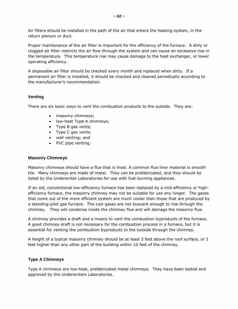
~ 62 ~
Air filters should be installed in the path of the air that enters the heating system, in the
return plenum or duct.
Proper maintenance of the air filter is important for the efficiency of the furnace. A dirty or
clogged air filter restricts the air flow through the system and can cause an excessive rise in
the temperature. This temperature rise may cause damage to the heat exchanger, or lower
operating efficiency.
A disposable air filter should be checked every month and replaced when dirty. If a
permanent air filter is installed, it should be checked and cleaned periodically according to
the manufacturer’s recommendation.
Venting
There are six basic ways to vent the combustion products to the outside. They are:
masonry chimneys;
low-heat Type A chimneys;
Type B gas vents;
Type C gas vents;
wall venting; and
PVC pipe venting.
Masonry Chimneys
Masonry chimneys should have a flue that is lined. A common flue liner material is smooth
tile. Many chimneys are made of metal. They can be prefabricated, and they should be
listed by the Underwriter Laboratories for use with fuel-burning appliances.
If an old, conventional low-efficiency furnace has been replaced by a mid-efficiency or high-
efficiency furnace, the masonry chimney may not be suitable for use any longer. The gases
that come out of the more efficient system are much cooler than those that are produced by
a standing-pilot gas furnace. The cool gases are not buoyant enough to rise through the
chimney. They will condense inside the chimney flue and will damage the masonry flue.
A chimney provides a draft and a means to vent the combustion byproducts of the furnace.
A good chimney draft is not necessary for the combustion process in a furnace, but it is
essential for venting the combustion byproducts to the outside through the chimney.
A height of a typical masonry chimney should be at least 3 feet above the roof surface, or 2
feet higher than any other part of the building within 10 feet of the chimney.
Type A Chimneys
Type A chimneys are low-heat, prefabricated metal chimneys. They have been tested and
approved by the Underwriters Laboratories.

~ 63 ~
Type B Gas Vents
Type B gas vents are UL-listed. They are recommended for all standard gas-fired heating
systems.
Type C Gas Vents
Type C gas vents are typically used for standard gas-fired furnaces that are installed in the
attic space.
Wall Venting
Wall venting involves having the combustion, combustion air, and combustion-product
venting all separated from the interior air of the room or space being heated. The
combustion gases are vented through the wall.
PVC Pipe Venting
High-efficiency furnaces use PVC piping to vent combustion gases and byproducts outside.
You usually see the PVC pipe extending from the furnace through the wall to the outside.
The pipe is usually a 2-inch diameter PVC pipe. PVC is also used to bring fresh outdoor air
into the system for combustion. The length could be very long, sometimes as much as 60
feet.
The temperatures of the combustion byproducts are low (100° F to 150° F). That’s very
cool. The PVC does not melt. It will feel warm to the touch. That’s one way to determine
which pipe is the exhaust.
PVC pipes need a proper slope. The pipe should be sloped down and toward the furnace, or
slope up and away from the furnace. Typically, a ¼-inch per linear foot is recommended.
The pipe should be sloped and adequately supported so that condensate does not form and
puddle inside a sagging part of the vent pipe. The condensate should be allowed to drain
back toward the furnace. A PVC vent pipe will likely indicate a high-efficiency gas heating
system. High-efficiency furnaces should not be vented into a chimney. The exhaust gases
from a high-efficiency heating system are too cool to create enough chimney draft. The
cool gases will condense inside the chimney and will cause damage.
Flue Pipe
The flue is the passage through which the gases from the combustion chamber of the
heating system move to the outside. A flue is also referred to as the flue pipe, vent pipe,
or vent connector. A chimney flue is the flue that is inside a chimney. The flue from the
heating system to the chimney is often called the vent connector, chimney connector or
smoke pipe. A flue outlet, or vent, is the opening in a heating system through which the
flue gases move.
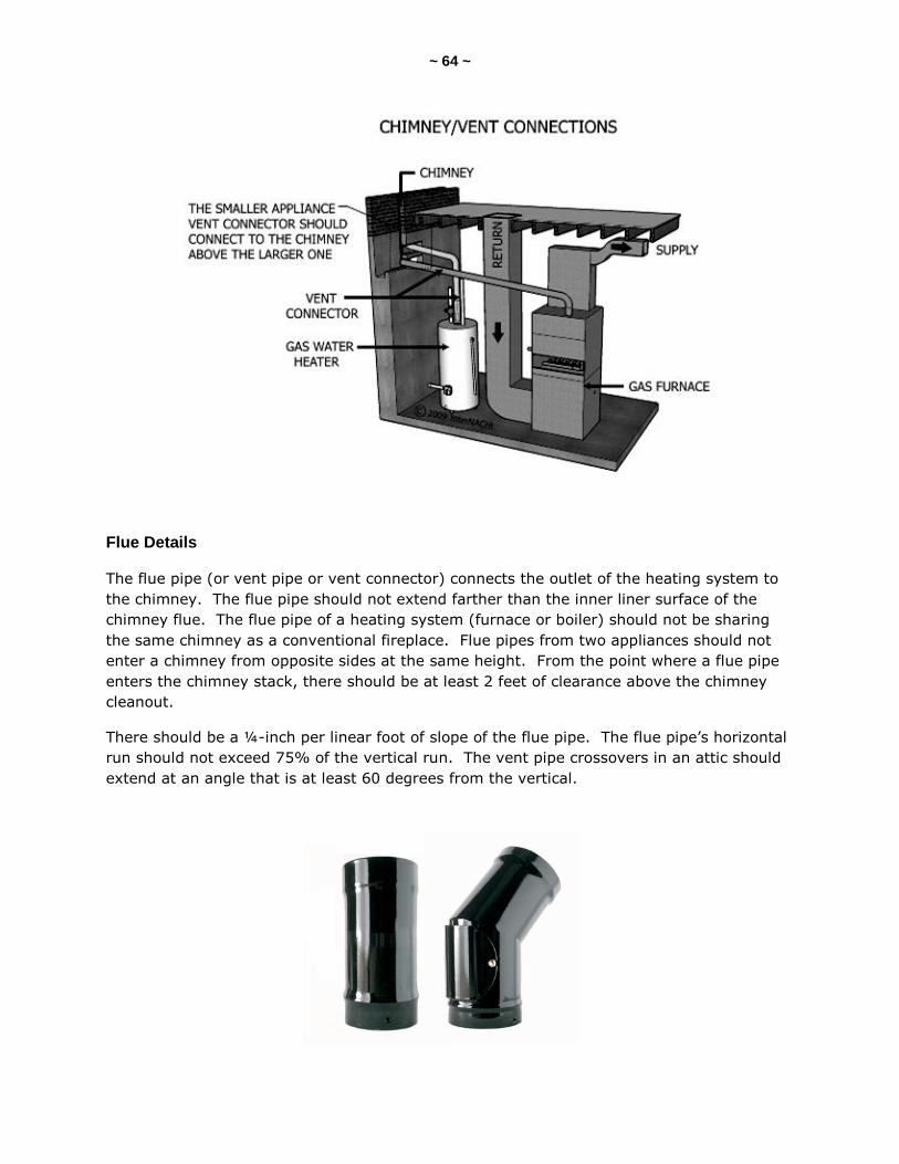
~ 64 ~
Flue Details
The flue pipe (or vent pipe or vent connector) connects the outlet of the heating system to
the chimney. The flue pipe should not extend farther than the inner liner surface of the
chimney flue. The flue pipe of a heating system (furnace or boiler) should not be sharing
the same chimney as a conventional fireplace. Flue pipes from two appliances should not
enter a chimney from opposite sides at the same height. From the point where a flue pipe
enters the chimney stack, there should be at least 2 feet of clearance above the chimney
cleanout.
There should be a ¼-inch per linear foot of slope of the flue pipe. The flue pipe’s horizontal
run should not exceed 75% of the vertical run. The vent pipe crossovers in an attic should
extend at an angle that is at least 60 degrees from the vertical.

~ 65 ~
The flue pipe should be at least the same diameter-size as the outlet of the furnace. The
diameter-size of the flue pipe should never be reduced.

~ 66 ~
Draft Hood
A draft hood is installed on standing-pilot gas furnaces. Mid- and high-efficiency gas
furnaces do not have draft hoods. Draft hoods are attached to the top of the furnace above
the flue outlet. It is sometimes called a draft diverter.
The draft hood functions to produce a constant, low draft of air for the combustion
chamber. It allows dilution air to be drawn into the vent pipe. The dilution air cools the
exhaust and ensures a good draft. The draft hood also prevents large downdrafts from the
chimney affecting the burner.
The draft hood can be built into the furnace cabinet (internal draft diverter), or it could be
installed separately above the top of the heating unit. If it is installed within the furnace
cabinet, it becomes part of the manifold that collects all of the exhaust gases that come out
of each cell of the exchanger.

~ 67 ~
Heat Shield
Most conventional gas furnaces have a heat shield. This prevents flame rollout. It contains
the flames inside the burner chamber. It also protects the burners against strong drafts.
Gas-Supply Piping
The gas-supply piping is sometimes referred to as the gas-service piping. The gas piping
must be installed properly according to the local codes and ordinances, or, if unavailable,
the codes in standards such as the National Fuel Gas Code. The codes will recommend the
proper sizing of the pipes for the required gas volumes.
Usually, the inlet gas supply pipe should be at least a ½-inch pipe. The gas line from the
supply should serve only a single heating system. There should be drip leg installed near the
heating system.
A drip leg should be installed at the bottom of the gas-supply riser near the heating
system. The drip leg collects dirt, moisture and impurities that float in the gas.

~ 68 ~
A gas shut-off valve should be installed near the heating system. This manual shut-off
valve is sometimes installed on the gas-supply riser, or on the horizontal pipe between the
riser and the union fitting near the heating system.
The union-joint fitting should be installed between the manual shut-off valve and the main
gas-control valve on the heating system. The union joint allows the gas-burner assembly to
be easily disconnected for service.
Gas Furnace Inspection, Service and Maintenance
The heating system should be inspected by a qualified service technician every year. It is
recommended that the system be inspected before the heating season. The technician can
ensure the continued safe operation of the heating system.

~ 69 ~
QUIZ 6
1. A ______ is approximately the amount of energy needed to heat 1 pound of water to 1 degree Fahrenheit.
BTU
gas-foot-pound
steady-state
2. The older gas furnaces have a/n ______-pilot light that is always burning.
standing
direct-spark
intermittent
3. T/F: Inside a high-efficiency furnace, there may be at least two heat exchangers.
True
False
4. ________ air is that which mixes with the gas before going to the burners.
Secondary
Primary
Crossover
Answer Key to Quiz 6
1. A BTU is approximately the amount of energy needed to heat 1 pound of water to 1 degree Fahrenheit.
2. The older gas furnaces have a/n standing-pilot light that is always burning.
3. T/F: Inside a high-efficiency furnace, there may be at least two heat exchangers. Answer: True
4. Primary air is that which mixes with the gas before going to the burners.

~ 70 ~
SECTION 13: OIL FURNACES
There are different types of oil furnaces according to their orientation. They can be
described as:
upflow;
downflow (or counterflow); or
horizontal-flow.
They can be of various capacities, sizes and efficiencies. They can be installed in various
spaces, including basements, attic and closets. All furnaces should be UL-listed and tested
for safety.
Conventional Oil Furnace
Most residential oil furnaces being used today are conventional. They will typically not be
high-efficiency, condensing heating systems. The conventional furnaces are slowly being
replaced by mid- and high-efficiency heating systems. If you are inspecting a conventional
oil furnace with a cast-iron burner, it likely has an AFUE (seasonal efficiency rating) of 60%,
which is low-efficiency.
Heating Cycle
Let’s go over the general steps to the heating cycle for a conventional oil furnace. First, the
thermostat calls for heat. The thermostat closes an electrical circuit to a control relay.
Electrical current is sent to both the oil burner transformer and the fuel pump motor.
The motor on the fuel pump sucks fuel oil from the supply tank and pushes it to the burner
nozzle of the gun assembly. At the burner nozzle, fuel is combined with air. The fuel is
atomized. A blower sends combustion air into the combustion chamber. The transformer
sends a high-voltage electric current to the electrodes in the gun assembly. The atomized
air-fuel mixture is ignited. There is a rumbling sound created by this burner. The heating
cycle has begun.
There is a safety device in operation when the burner is shooting flames. It is a cadmium
solenoid photo-cell, referred to as a cad cell. The cad cell “looks” for a flame and confirms
that it exists. It can detect the flame located in the combustion chamber. If the cad cell
doesn’t see the flame within a few seconds, the circuit to the burner is opened and the
burner is shut down.
Some oil furnaces don't have a cad cell and, instead, have a stack relay. A stack relay
senses heat instead of light. If the stack relay does not sense heat, the circuit to the burner
is opened and the burner is shut down.
This safety device in an oil furnace is similar to the function of the fan and limit control for a
gas furnace.
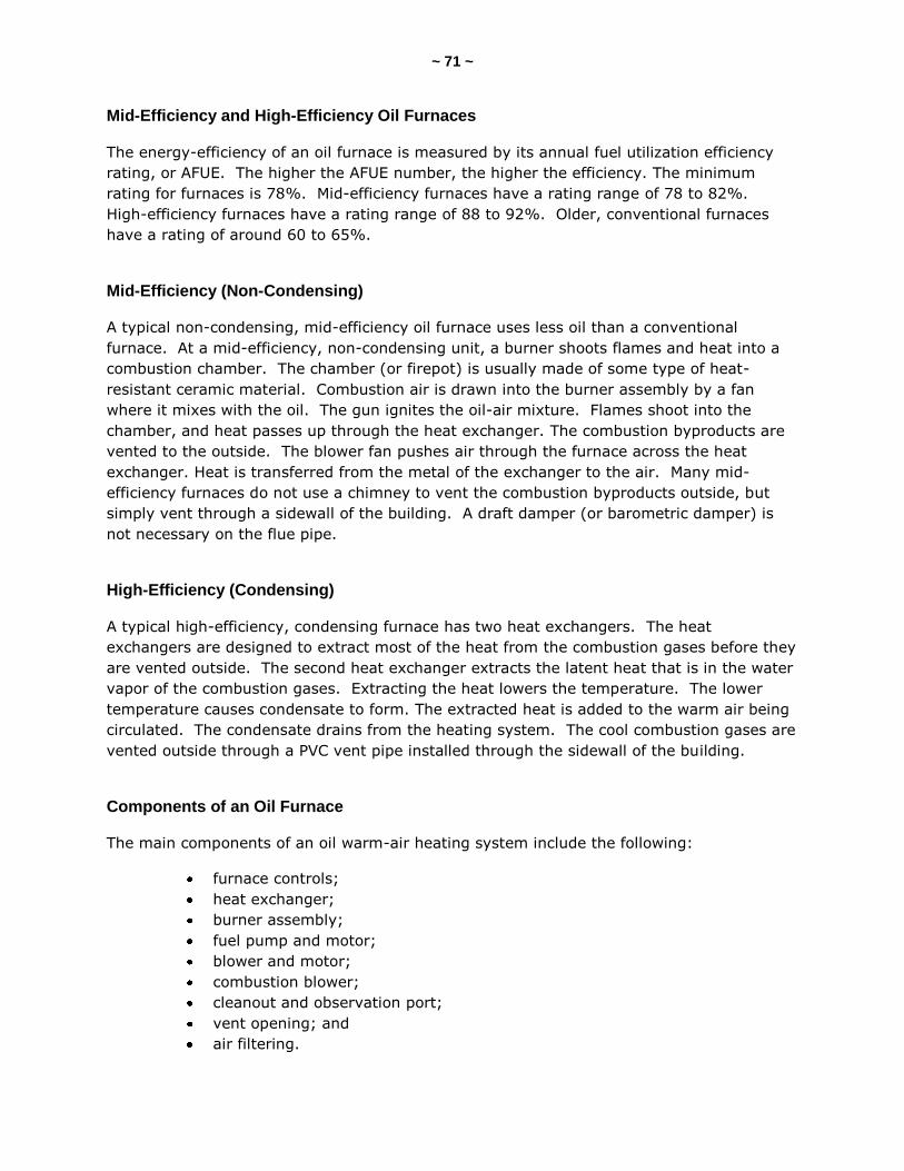
~ 71 ~
Mid-Efficiency and High-Efficiency Oil Furnaces
The energy-efficiency of an oil furnace is measured by its annual fuel utilization efficiency
rating, or AFUE. The higher the AFUE number, the higher the efficiency. The minimum
rating for furnaces is 78%. Mid-efficiency furnaces have a rating range of 78 to 82%.
High-efficiency furnaces have a rating range of 88 to 92%. Older, conventional furnaces
have a rating of around 60 to 65%.
Mid-Efficiency (Non-Condensing)
A typical non-condensing, mid-efficiency oil furnace uses less oil than a conventional
furnace. At a mid-efficiency, non-condensing unit, a burner shoots flames and heat into a
combustion chamber. The chamber (or firepot) is usually made of some type of heat-
resistant ceramic material. Combustion air is drawn into the burner assembly by a fan
where it mixes with the oil. The gun ignites the oil-air mixture. Flames shoot into the
chamber, and heat passes up through the heat exchanger. The combustion byproducts are
vented to the outside. The blower fan pushes air through the furnace across the heat
exchanger. Heat is transferred from the metal of the exchanger to the air. Many mid-
efficiency furnaces do not use a chimney to vent the combustion byproducts outside, but
simply vent through a sidewall of the building. A draft damper (or barometric damper) is
not necessary on the flue pipe.
High-Efficiency (Condensing)
A typical high-efficiency, condensing furnace has two heat exchangers. The heat
exchangers are designed to extract most of the heat from the combustion gases before they
are vented outside. The second heat exchanger extracts the latent heat that is in the water
vapor of the combustion gases. Extracting the heat lowers the temperature. The lower
temperature causes condensate to form. The extracted heat is added to the warm air being
circulated. The condensate drains from the heating system. The cool combustion gases are
vented outside through a PVC vent pipe installed through the sidewall of the building.
Components of an Oil Furnace
The main components of an oil warm-air heating system include the following:
furnace controls;
heat exchanger;
burner assembly;
fuel pump and motor;
blower and motor;
combustion blower;
cleanout and observation port;
vent opening; and
air filtering.
~ 72 ~
Furnace Controls
Furnace controls for a typical oil furnace include the following:
thermostat;
cad cell;
fan controls; and
delayed-action solenoid valve.
The thermostat controls the operation of the heating system. It senses the air
temperature in the room that is being heated. It calls for heat.
The cad cell is a safety device. It “looks” for the flame inside the burner chamber. It
confirms that a flame exists when the burner starts. If the cad cell doesn’t see the flame
within a few seconds, the circuit to the burner is opened and the burner is shut down.
The fan and limit control is a safety device. It is installed in a metal box on the outside of
the oil furnace. It senses the air temperature that passes through the furnace plenum. It is
located on the house-air side of the heat exchanger, and it measures the temperature of the
air that is coming out of the heat exchanger. It controls the operation of the blower fan
within a temperature range. It prevents the furnace from overheating by turning off the
burner if the furnace gets too hot.
When the air coming out of the furnace heat exchanger is warm enough, it turns on the
blower fan and pushes air to the rooms and spaces of the building being heated.
The fan and limit control has two settings: high and low. When the temperature in the
house reaches the upper setting, the burner turns off. The blower fan runs until the
temperature of the heat exchanger lowers and reaches the low setting, and then the blower
fan turns off.
The control is usually set to turn the blower fan on when the air temperature reaches
around 120° F to 150° F. That same sensor control also turns the fan off when the air
temperature drops to around 80° F to 110° F.
Some modern oil furnaces are equipped with electronic devices that control the blower fan
instead of the fan and limit-control switches.
Heat Exchanger for an Oil Furnace
The heat exchanger is the part of the furnace that transfers heat energy from the material
of the exchanger to the air that passes through the furnace and around the exchanger.
The exchanger is made of heavy-gauge steel. The exchanger has an upper and a lower
chamber. The lower part contains the combustion chamber, where the flames are.

~ 73 ~
Combustion Chamber (Firepot)
The combustion chamber (often referred to as the firepot) is where the combustion takes
place. The combustion chamber is inside the lower part of the heat exchanger. The
combustion chamber is made of a material that can withstand very hot temperatures.
Combustion chambers can be made of stainless steel, cast iron, or a refractory material,
such as firebrick or ceramic clay. The nozzle of the burner-gun assembly sticks into the
chamber area. Most chambers are round; some are square and octagonal. Some modern
oil furnaces have sealed combustion chambers that help with increasing efficiency.
Combustion chambers are typically about 10 inches in diameter (or wide) and 13 inches
tall.
Oil Burners
The most common oil burner that you will see is the atomizing oil burner, sometimes called
a gun-type burner. There are some special burners called vaporizing or pot-type burners.
There are a few parts to an atomizing oil-burner assembly that are important, including:
burner control;
re-set button;
oil pump;
ignition transformer;
cad cell;
gun;
nozzle; and
electrodes.

~ 74 ~
An atomizing burner uses an electrical pump and a nozzle that atomizes the oil. “Atomizing”
means that the oil is turned from a liquid to a spray of fine droplets. This spray is mixed
with air. The mixture is then ignited by a high-voltage spark.

~ 75 ~
The burner combines fuel oil with air and mixes them. It delivers the fuel-air mixture to the
gun and ignites it.
The oil pump on the oil burner sucks oil from the oil storage tank and sends it to the gun.
The pump delivers the oil under pressure (between around 75 to 120 psi). The pump is
usually mounted on the side of the burner assembly.
Air for combustion is sucked into the burner by a combustion-air fan. Air gets sucked
through the air ports and is forced down the blast tube of the gun into the head where the
electrodes are located. The barrel of the gun is a steel tube about 3 inches in diameter and
about 1 foot long. The electrodes are at the end of the tube.
On modern burners, the flame-retention burner device is usually located at the very end of
the tube.
Electrodes
The electrodes behave like a big spark plug. The electrodes create a high-voltage spark and
the spark ignites the oil spray. Once the flame is confirmed, the spark shuts off and the
flame continues.
The combustion is contained inside the fire pot or refractor chamber pot.
Ignition Transformer
The ignition transformer takes the 120-volt electrical current and changes it into a very high
DC voltage for the electrodes to create a spark.
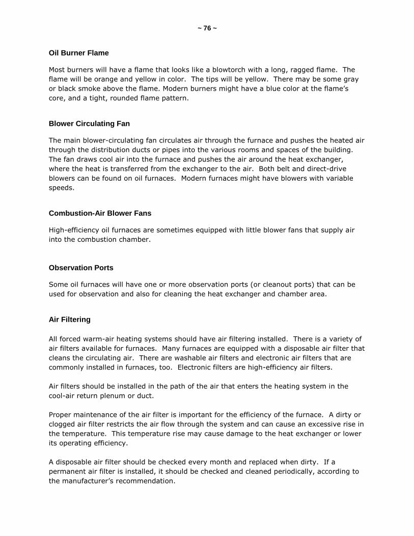
~ 76 ~
Oil Burner Flame
Most burners will have a flame that looks like a blowtorch with a long, ragged flame. The
flame will be orange and yellow in color. The tips will be yellow. There may be some gray
or black smoke above the flame. Modern burners might have a blue color at the flame’s
core, and a tight, rounded flame pattern.
Blower Circulating Fan
The main blower-circulating fan circulates air through the furnace and pushes the heated air
through the distribution ducts or pipes into the various rooms and spaces of the building.
The fan draws cool air into the furnace and pushes the air around the heat exchanger,
where the heat is transferred from the exchanger to the air. Both belt and direct-drive
blowers can be found on oil furnaces. Modern furnaces might have blowers with variable
speeds.
Combustion-Air Blower Fans
High-efficiency oil furnaces are sometimes equipped with little blower fans that supply air
into the combustion chamber.
Observation Ports
Some oil furnaces will have one or more observation ports (or cleanout ports) that can be
used for observation and also for cleaning the heat exchanger and chamber area.
Air Filtering
All forced warm-air heating systems should have air filtering installed. There is a variety of
air filters available for furnaces. Many furnaces are equipped with a disposable air filter that
cleans the circulating air. There are washable air filters and electronic air filters that are
commonly installed in furnaces, too. Electronic filters are high-efficiency air filters.
Air filters should be installed in the path of the air that enters the heating system in the
cool-air return plenum or duct.
Proper maintenance of the air filter is important for the efficiency of the furnace. A dirty or
clogged air filter restricts the air flow through the system and can cause an excessive rise in
the temperature. This temperature rise may cause damage to the heat exchanger or lower
its operating efficiency.
A disposable air filter should be checked every month and replaced when dirty. If a
permanent air filter is installed, it should be checked and cleaned periodically, according to
the manufacturer’s recommendation.
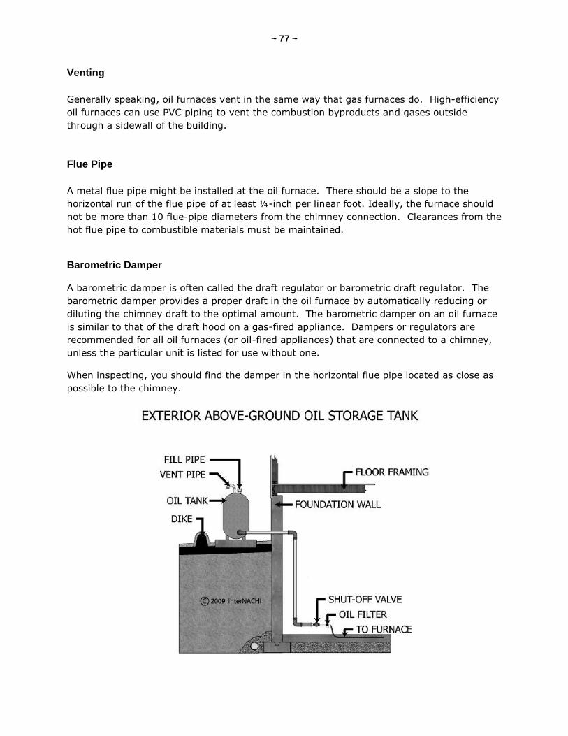
~ 77 ~
Venting
Generally speaking, oil furnaces vent in the same way that gas furnaces do. High-efficiency
oil furnaces can use PVC piping to vent the combustion byproducts and gases outside
through a sidewall of the building.
Flue Pipe
A metal flue pipe might be installed at the oil furnace. There should be a slope to the
horizontal run of the flue pipe of at least ¼-inch per linear foot. Ideally, the furnace should
not be more than 10 flue-pipe diameters from the chimney connection. Clearances from the
hot flue pipe to combustible materials must be maintained.
Barometric Damper
A barometric damper is often called the draft regulator or barometric draft regulator. The
barometric damper provides a proper draft in the oil furnace by automatically reducing or
diluting the chimney draft to the optimal amount. The barometric damper on an oil furnace
is similar to that of the draft hood on a gas-fired appliance. Dampers or regulators are
recommended for all oil furnaces (or oil-fired appliances) that are connected to a chimney,
unless the particular unit is listed for use without one.
When inspecting, you should find the damper in the horizontal flue pipe located as close as
possible to the chimney.
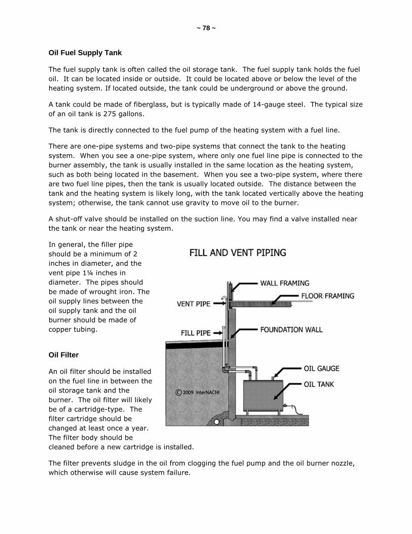
~ 78 ~
Oil Fuel Supply Tank
The fuel supply tank is often called the oil storage tank. The fuel supply tank holds the fuel
oil. It can be located inside or outside. It could be located above or below the level of the
heating system. If located outside, the tank could be underground or above the ground.
A tank could be made of fiberglass, but is typically made of 14-gauge steel. The typical size
of an oil tank is 275 gallons.
The tank is directly connected to the fuel pump of the heating system with a fuel line.
There are one-pipe systems and two-pipe systems that connect the tank to the heating
system. When you see a one-pipe system, where only one fuel line pipe is connected to the
burner assembly, the tank is usually installed in the same location as the heating system,
such as both being located in the basement. When you see a two-pipe system, where there
are two fuel line pipes, then the tank is usually located outside. The distance between the
tank and the heating system is likely long, with the tank located vertically above the heating
system; otherwise, the tank cannot use gravity to move oil to the burner.
A shut-off valve should be installed on the suction line. You may find a valve installed near
the tank or near the heating system.
In general, the filler pipe
should be a minimum of 2
inches in diameter, and the
vent pipe 1¼ inches in
diameter. The pipes should
be made of wrought iron. The
oil supply lines between the
oil supply tank and the oil
burner should be made of
copper tubing.
Oil Filter
An oil filter should be installed
on the fuel line in between the
oil storage tank and the
burner. The oil filter will likely
be of a cartridge-type. The
filter cartridge should be
changed at least once a year.
The filter body should be
cleaned before a new cartridge is installed.
The filter prevents sludge in the oil from clogging the fuel pump and the oil burner nozzle,
which otherwise will cause system failure.
~ 79 ~
SECTION 14: HIGH-EFFICIENCY HEAT EXCHANGERS
High-efficiency furnaces use the principle that as hot gases cool, they release a lot of heat
energy as they change their state from a gas to a liquid. Burning natural gas creates water
(vapor) and carbon dioxide. As we cool the exhaust byproducts, heat is released. If we can
cool the vapor into a liquid, a tremendous amount of heat can be extracted.
We can cool that vapor inside a furnace using the heat exchangers. High-efficiency furnaces
have at least two heat exchangers. The exchanger inside a high-efficiency is very long --
longer than that of a conventional or mid-efficiency furnace. As the hot exhaust gases flow
through the long exchanger, the gases cool to the point that they condense. By the time
the exhaust combustion gases leave the high-efficiency furnace, the gas temperature could
be around 100° F.
Condensation takes place in the second (or third) heat exchanger. That’s why they are
usually made out of stainless steel, because it is more corrosion-resistant. Usually, the first
heat exchanger is made of conventional galvanized steel.
The condensate comes out of the exchanger and drains into tubes or pipes. The condensate
might discharge into a drain fitting, a floor drain, a drain pipe, or a condensate pump. It is
not good practice to simply drain the condensate through the floor and into the gravel and
soil below the concrete floor. The condensate water is slightly acidic. It’s not as acidic as
vinegar, but some jurisdictions restrict the discharge of the condensate.
When a high-efficiency condensing furnace is operating, a quart of condensate water may
drain out every 30 minutes. That’s a lot of water.
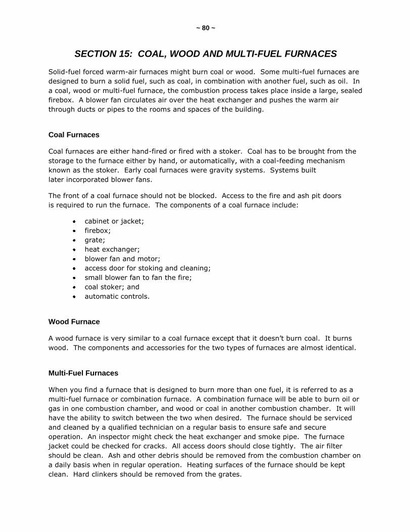
~ 80 ~
SECTION 15: COAL, WOOD AND MULTI-FUEL FURNACES
Solid-fuel forced warm-air furnaces might burn coal or wood. Some multi-fuel furnaces are
designed to burn a solid fuel, such as coal, in combination with another fuel, such as oil. In
a coal, wood or multi-fuel furnace, the combustion process takes place inside a large, sealed
firebox. A blower fan circulates air over the heat exchanger and pushes the warm air
through ducts or pipes to the rooms and spaces of the building.
Coal Furnaces
Coal furnaces are either hand-fired or fired with a stoker. Coal has to be brought from the
storage to the furnace either by hand, or automatically, with a coal-feeding mechanism
known as the stoker. Early coal furnaces were gravity systems. Systems built
later incorporated blower fans.
The front of a coal furnace should not be blocked. Access to the fire and ash pit doors
is required to run the furnace. The components of a coal furnace include:
cabinet or jacket;
firebox;
grate;
heat exchanger;
blower fan and motor;
access door for stoking and cleaning;
small blower fan to fan the fire;
coal stoker; and
automatic controls.
Wood Furnace
A wood furnace is very similar to a coal furnace except that it doesn’t burn coal. It burns
wood. The components and accessories for the two types of furnaces are almost identical.
Multi-Fuel Furnaces
When you find a furnace that is designed to burn more than one fuel, it is referred to as a
multi-fuel furnace or combination furnace. A combination furnace will be able to burn oil or
gas in one combustion chamber, and wood or coal in another combustion chamber. It will
have the ability to switch between the two when desired. The furnace should be serviced
and cleaned by a qualified technician on a regular basis to ensure safe and secure
operation. An inspector might check the heat exchanger and smoke pipe. The furnace
jacket could be checked for cracks. All access doors should close tightly. The air filter
should be clean. Ash and other debris should be removed from the combustion chamber on
a daily basis when in regular operation. Heating surfaces of the furnace should be kept
clean. Hard clinkers should be removed from the grates.
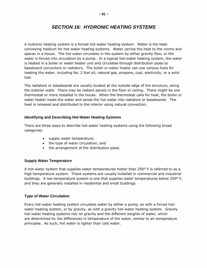
~ 81 ~
SECTION 16: HYDRONIC HEATING SYSTEMS
A hydronic heating system is a forced hot-water heating system. Water is the heat-
conveying medium for hot-water heating systems. Water carries the heat to the rooms and
spaces in a house. The hot water circulates in the system by either gravity flow, or the
water is forced into circulation by a pump. In a typical hot-water heating system, the water
is heated in a boiler or water heater unit and circulates through distribution pipes to
baseboard convectors or radiators. The boiler or water heater can use various fuels for
heating the water, including No. 2 fuel oil, natural gas, propane, coal, electricity, or a solid
fuel.
The radiators or baseboards are usually located at the outside edge of the structure, along
the exterior walls. There may be radiant panels in the floor or ceiling. There might be one
thermostat or more installed in the house. When the thermostat calls for heat, the boiler or
water heater heats the water and sends the hot water into radiators or baseboards. The
heat is released and distributed to the interior using natural convection.
Identifying and Describing Hot-Water Heating Systems
There are three ways to describe hot-water heating systems using the following broad
categories:
supply water temperature;
the type of water circulation; and
the arrangement of the distribution pipes.
Supply Water Temperature
A hot-water system that supplies water temperatures hotter than 250° F is referred to as a
high-temperature system. These systems are usually installed in commercial and industrial
buildings. A low-temperature system is one that supplies water temperatures below 250° F,
and they are generally installed in residential and small buildings.
Type of Water Circulation
Every hot-water heating system circulates water by either a pump, as with a forced hot-
water heating system, or by gravity, as with a gravity hot-water heating system. Gravity
hot-water heating systems rely on gravity and the different weights of water, which
are determined by the differences in temperature of the water, similar to air temperature
principles. As such, hot water is lighter than cold water.

~ 82 ~
Arrangement of the Distribution Pipes
There are four types of distribution-pipe arrangements for a hot-water heating system.
They include:
one-pipe system;
series-loop system;
two-pipe direct-return system; and
two-pipe reverse-return system.
One-Pipe System
In a one-pipe system, there is one single pipe that carries the hot water throughout the
system. That single pipe carries the hot water to the radiators or baseboard convectors,
and it also carries the cool water back to the boiler or water-heating unit. Each heat-
emitting unit (radiator or baseboard) is connected to this main, single pipe with two smaller
branch pipes, which are the feed line and the return line.
One-pipe systems can be forced- or gravity-types.
The main advantage of a one-pipe system is that each radiator or convector can be
controlled individually without interfering with the flow of water to the other heat-emitting
units. Zoning can be achieved in a one-pipe system by installing a separate loop, a pump
(for forced), and another thermostat.
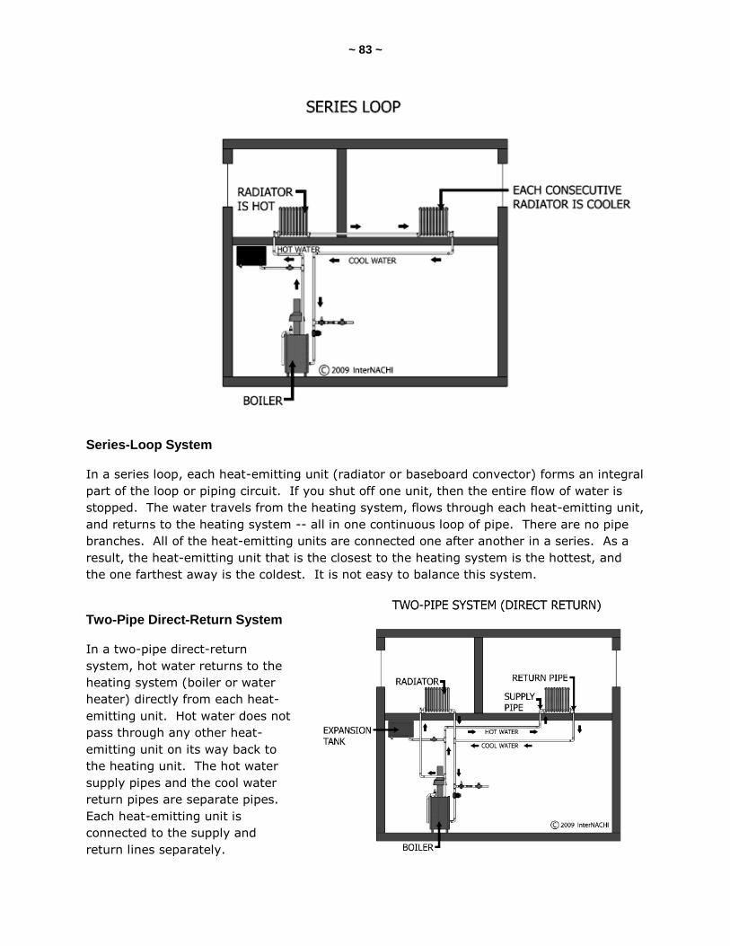
~ 83 ~
Series-Loop System
In a series loop, each heat-emitting unit (radiator or baseboard convector) forms an integral
part of the loop or piping circuit. If you shut off one unit, then the entire flow of water is
stopped. The water travels from the heating system, flows through each heat-emitting unit,
and returns to the heating system -- all in one continuous loop of pipe. There are no pipe
branches. All of the heat-emitting units are connected one after another in a series. As a
result, the heat-emitting unit that is the closest to the heating system is the hottest, and
the one farthest away is the coldest. It is not easy to balance this system.
Two-Pipe Direct-Return System
In a two-pipe direct-return
system, hot water returns to the
heating system (boiler or water
heater) directly from each heat-
emitting unit. Hot water does not
pass through any other heat-
emitting unit on its way back to
the heating unit. The hot water
supply pipes and the cool water
return pipes are separate pipes.
Each heat-emitting unit is
connected to the supply and
return lines separately.
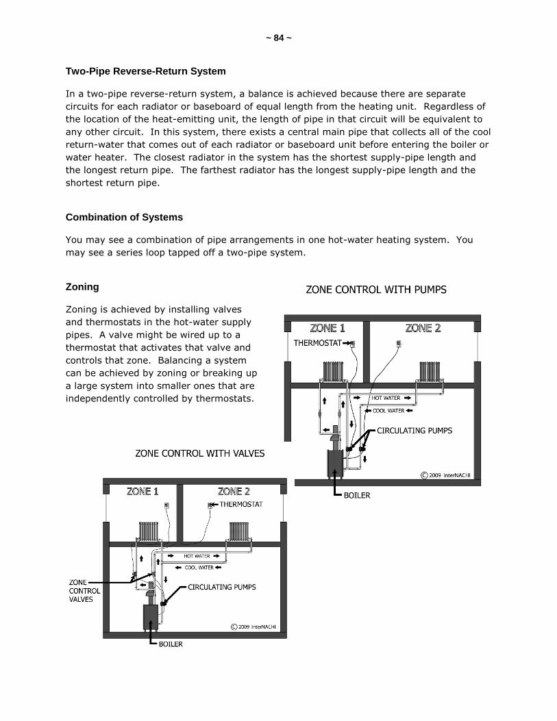
~ 84 ~
Two-Pipe Reverse-Return System
In a two-pipe reverse-return system, a balance is achieved because there are separate
circuits for each radiator or baseboard of equal length from the heating unit. Regardless of
the location of the heat-emitting unit, the length of pipe in that circuit will be equivalent to
any other circuit. In this system, there exists a central main pipe that collects all of the cool
return-water that comes out of each radiator or baseboard unit before entering the boiler or
water heater. The closest radiator in the system has the shortest supply-pipe length and
the longest return pipe. The farthest radiator has the longest supply-pipe length and the
shortest return pipe.
Combination of Systems
You may see a combination of pipe arrangements in one hot-water heating system. You
may see a series loop tapped off a two-pipe system.
Zoning
Zoning is achieved by installing valves
and thermostats in the hot-water supply
pipes. A valve might be wired up to a
thermostat that activates that valve and
controls that zone. Balancing a system
can be achieved by zoning or breaking up
a large system into smaller ones that are
independently controlled by thermostats.
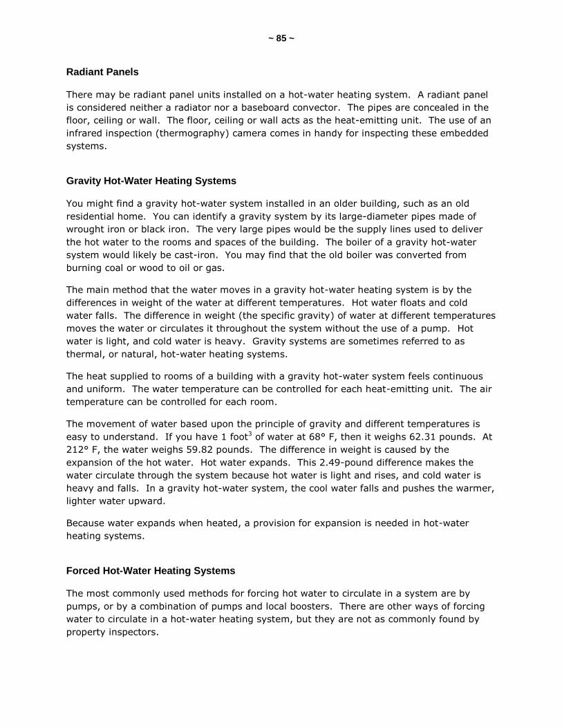
~ 85 ~
Radiant Panels
There may be radiant panel units installed on a hot-water heating system. A radiant panel
is considered neither a radiator nor a baseboard convector. The pipes are concealed in the
floor, ceiling or wall. The floor, ceiling or wall acts as the heat-emitting unit. The use of an
infrared inspection (thermography) camera comes in handy for inspecting these embedded
systems.
Gravity Hot-Water Heating Systems
You might find a gravity hot-water system installed in an older building, such as an old
residential home. You can identify a gravity system by its large-diameter pipes made of
wrought iron or black iron. The very large pipes would be the supply lines used to deliver
the hot water to the rooms and spaces of the building. The boiler of a gravity hot-water
system would likely be cast-iron. You may find that the old boiler was converted from
burning coal or wood to oil or gas.
The main method that the water moves in a gravity hot-water heating system is by the
differences in weight of the water at different temperatures. Hot water floats and cold
water falls. The difference in weight (the specific gravity) of water at different temperatures
moves the water or circulates it throughout the system without the use of a pump. Hot
water is light, and cold water is heavy. Gravity systems are sometimes referred to as
thermal, or natural, hot-water heating systems.
The heat supplied to rooms of a building with a gravity hot-water system feels continuous
and uniform. The water temperature can be controlled for each heat-emitting unit. The air
temperature can be controlled for each room.
The movement of water based upon the principle of gravity and different temperatures is
easy to understand. If you have 1 foot3 of water at 68° F, then it weighs 62.31 pounds. At
212° F, the water weighs 59.82 pounds. The difference in weight is caused by the
expansion of the hot water. Hot water expands. This 2.49-pound difference makes the
water circulate through the system because hot water is light and rises, and cold water is
heavy and falls. In a gravity hot-water system, the cool water falls and pushes the warmer,
lighter water upward.
Because water expands when heated, a provision for expansion is needed in hot-water
heating systems.
Forced Hot-Water Heating Systems
The most commonly used methods for forcing hot water to circulate in a system are by
pumps, or by a combination of pumps and local boosters. There are other ways of forcing
water to circulate in a hot-water heating system, but they are not as commonly found by
property inspectors.
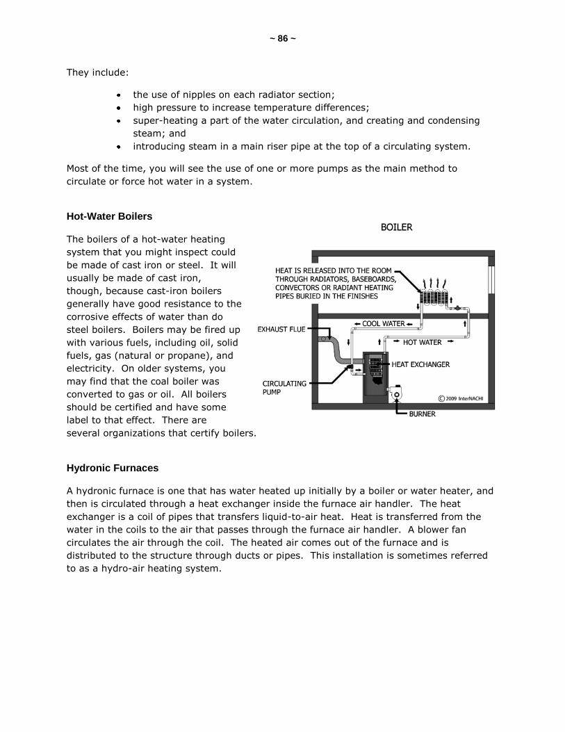
~ 86 ~
They include:
the use of nipples on each radiator section;
high pressure to increase temperature differences;
super-heating a part of the water circulation, and creating and condensing
steam; and
introducing steam in a main riser pipe at the top of a circulating system.
Most of the time, you will see the use of one or more pumps as the main method to
circulate or force hot water in a system.
Hot-Water Boilers
The boilers of a hot-water heating
system that you might inspect could
be made of cast iron or steel. It will
usually be made of cast iron,
though, because cast-iron boilers
generally have good resistance to the
corrosive effects of water than do
steel boilers. Boilers may be fired up
with various fuels, including oil, solid
fuels, gas (natural or propane), and
electricity. On older systems, you
may find that the coal boiler was
converted to gas or oil. All boilers
should be certified and have some
label to that effect. There are
several organizations that certify boilers.
Hydronic Furnaces
A hydronic furnace is one that has water heated up initially by a boiler or water heater, and
then is circulated through a heat exchanger inside the furnace air handler. The heat
exchanger is a coil of pipes that transfers liquid-to-air heat. Heat is transferred from the
water in the coils to the air that passes through the furnace air handler. A blower fan
circulates the air through the coil. The heated air comes out of the furnace and is
distributed to the structure through ducts or pipes. This installation is sometimes referred
to as a hydro-air heating system.
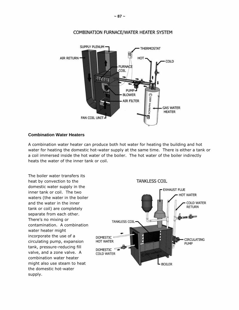
~ 87 ~
Combination Water Heaters
A combination water heater can produce both hot water for heating the building and hot
water for heating the domestic hot-water supply at the same time. There is either a tank or
a coil immersed inside the hot water of the boiler. The hot water of the boiler indirectly
heats the water of the inner tank or coil.
The boiler water transfers its
heat by convection to the
domestic water supply in the
inner tank or coil. The two
waters (the water in the boiler
and the water in the inner
tank or coil) are completely
separate from each other.
There’s no mixing or
contamination. A combination
water heater might
incorporate the use of a
circulating pump, expansion
tank, pressure-reducing fill
valve, and a zone valve. A
combination water heater
might also use steam to heat
the domestic hot-water
supply.
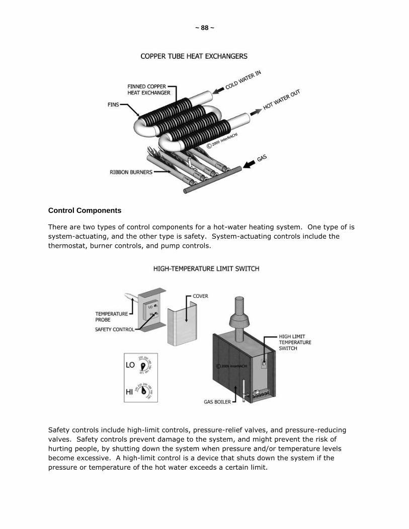
~ 88 ~
Control Components
There are two types of control components for a hot-water heating system. One type of is
system-actuating, and the other type is safety. System-actuating controls include the
thermostat, burner controls, and pump controls.
Safety controls include high-limit controls, pressure-relief valves, and pressure-reducing
valves. Safety controls prevent damage to the system, and might prevent the risk of
hurting people, by shutting down the system when pressure and/or temperature levels
become excessive. A high-limit control is a device that shuts down the system if the
pressure or temperature of the hot water exceeds a certain limit.
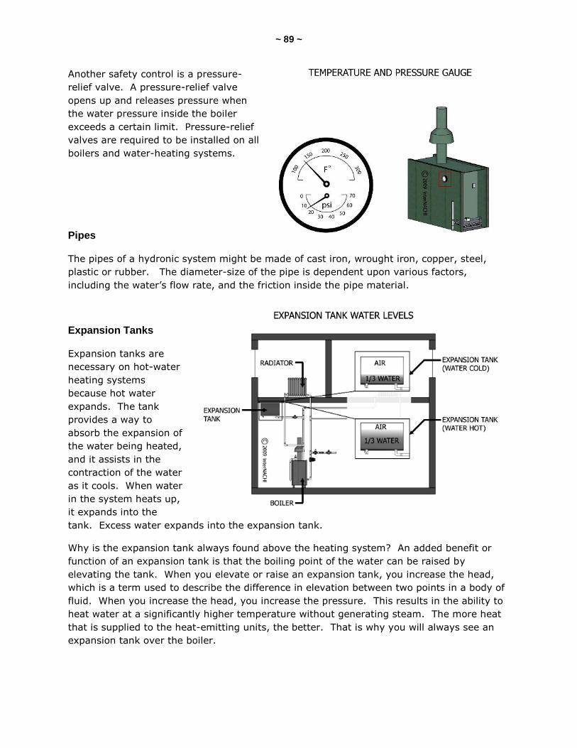
~ 89 ~
Another safety control is a pressure-
relief valve. A pressure-relief valve
opens up and releases pressure when
the water pressure inside the boiler
exceeds a certain limit. Pressure-relief
valves are required to be installed on all
boilers and water-heating systems.
Pipes
The pipes of a hydronic system might be made of cast iron, wrought iron, copper, steel,
plastic or rubber. The diameter-size of the pipe is dependent upon various factors,
including the water’s flow rate, and the friction inside the pipe material.
Expansion Tanks
Expansion tanks are
necessary on hot-water
heating systems
because hot water
expands. The tank
provides a way to
absorb the expansion of
the water being heated,
and it assists in the
contraction of the water
as it cools. When water
in the system heats up,
it expands into the
tank. Excess water expands into the expansion tank.
Why is the expansion tank always found above the heating system? An added benefit or
function of an expansion tank is that the boiling point of the water can be raised by
elevating the tank. When you elevate or raise an expansion tank, you increase the head,
which is a term used to describe the difference in elevation between two points in a body of
fluid. When you increase the head, you increase the pressure. This results in the ability to
heat water at a significantly higher temperature without generating steam. The more heat
that is supplied to the heat-emitting units, the better. That is why you will always see an
expansion tank over the boiler.
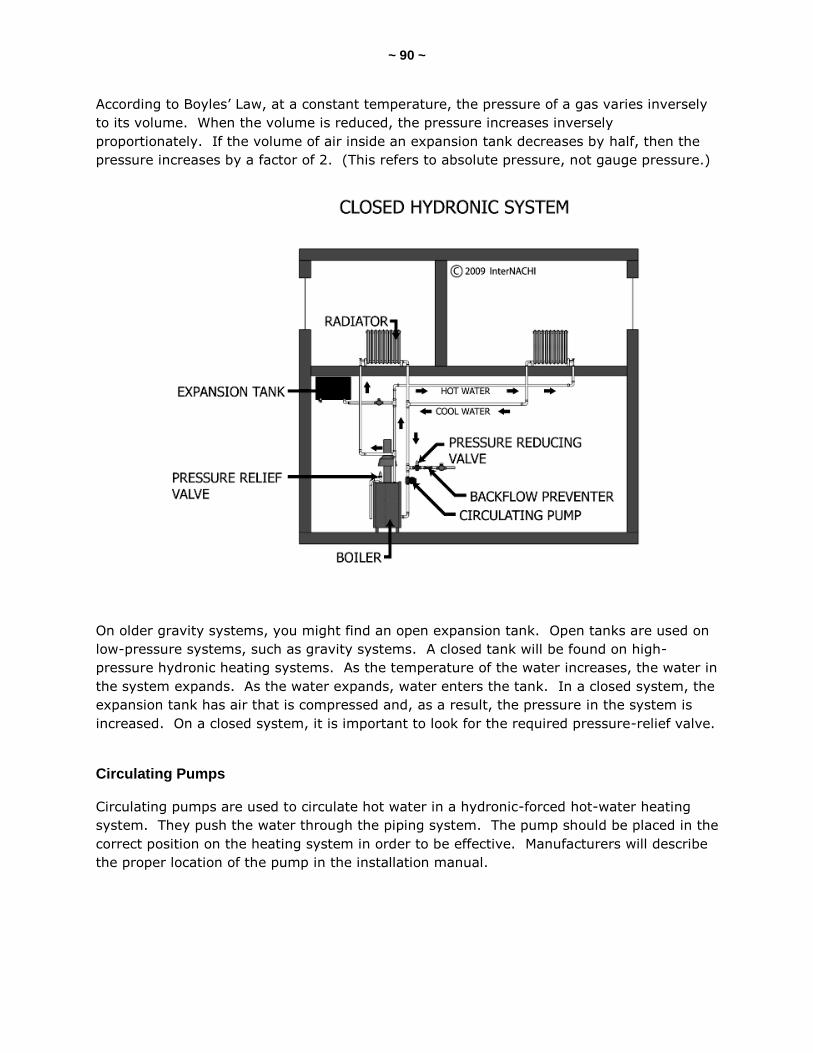
~ 90 ~
According to Boyles’ Law, at a constant temperature, the pressure of a gas varies inversely
to its volume. When the volume is reduced, the pressure increases inversely
proportionately. If the volume of air inside an expansion tank decreases by half, then the
pressure increases by a factor of 2. (This refers to absolute pressure, not gauge pressure.)
On older gravity systems, you might find an open expansion tank. Open tanks are used on
low-pressure systems, such as gravity systems. A closed tank will be found on high-
pressure hydronic heating systems. As the temperature of the water increases, the water in
the system expands. As the water expands, water enters the tank. In a closed system, the
expansion tank has air that is compressed and, as a result, the pressure in the system is
increased. On a closed system, it is important to look for the required pressure-relief valve.
Circulating Pumps
Circulating pumps are used to circulate hot water in a hydronic-forced hot-water heating
system. They push the water through the piping system. The pump should be placed in the
correct position on the heating system in order to be effective. Manufacturers will describe
the proper location of the pump in the installation manual.

~ 91 ~
Heat-Emitting Units
Heat-emitting units are the radiators, baseboard convectors, or other heat-emitting
components from which the heat is transferred into the room and spaces of the building.
Cast-iron radiators are common with older systems. They might be located on the floor or
hung off the wall. The radiators may be recessed inside a wall, or partially covered or
enclosed with a cabinet structure. If the radiator is covered, there should be openings
provided at the top and bottom of the covering or cabinet to allow air to circulate.
Convectors are tubes with fins on them.
The finned tubes will be
enclosed in a cabinet or
baseboard unit with
openings at the top and the
bottom.
As the hot water moves
through the tubes, the fins
get hot and radiate heat.
Room air enters the cabinet
or baseboard from the
bottom, and exits from the
top through openings.
Radiant floor units might be
made of flexible tubing
installed directly below the
floor. The heat is
transferred from the tubing
into the floor surface.
Flexible tubes and radiant
panels are also used as heat-emitting units in ceilings and walls.
Electric Hydronic Heating Systems
Hydronic heating systems may use electricity to heat the water. Electric hydronic heating
systems are usually compact electric boilers or water heaters, available in various small
sizes.
Advantages of Hydronic Heating Systems
There are many advantages to having a hydronic heating system. The heat is uniformly
delivered. Less energy is used to circulate water through pipes than is needed to circulate
air through a duct system. It is easy to zone a hydronic heating system. The indoor air-
quality issues are reduced because there is no air agitation as there is with a forced warm-
air system.
~ 92 ~
QUIZ 7
1. T/F: Air is the heat-conveying medium for hydronic heating systems.
True
False
2. If you have 1 foot-cubed of water at 68° F, then it weighs about ____ pounds.
62
47
26
3. T/F: Radiators and baseboard convectors are considered heat-emitting components.
True
False
Answer Key to Quiz 7
1. T/F: Air is the heat-conveying medium for hydronic heating systems. Answer: False
2. If you have 1 foot-cubed of water at 68° F, then it weighs about 62 pounds.
3. T/F: Radiators and baseboard convectors are considered heat-emitting components. Answer: True
~ 93 ~
SECTION 17: STEAM-HEATING SYSTEMS
Steam can be used as a heat-conveying medium. Steam-heating systems are not
commonly found in modern residential homes. You may find that the steam systems in
small commercial buildings have been replaced my other types of heating systems that
operate more efficiently and inexpensively.
In a steam-heating system, the boiler turns water into steam. The steam rises through
pipes to the heat-emitting units. Inside the units, the steam cools and condenses into
water. The condensate water returns to the boiler and the cycle begins again.
Identifying and Describing Steam-Heating Systems
There are a few ways to identify and describe a steam-heating system. The description of a
steam-heating system may include the following:
the pressure and vacuum conditions (low or high);
how the condensate water returns to the boiler (gravity or mechanical);
the piping (one-pipe or two-pipe);
type of piping circuit (divided, one-pipe, or loop);
direction of steam in the risers (upfeed or downfeed); and
location of the condensate returns (dry return or wet return).
Gravity Steam-Heating Systems
The distinguishing characteristic of a gravity steam-heating system is that the condensate
returns to the boiler from the heat-emitting units by gravity, rather than by mechanical
means.
One-Pipe Gravity Steam
In a one-pipe steam-heating system, the steam is carried around the lowest level of the
building -- typically, a basement. From that main circuit, branches to each individual heat-
emitting unit are taken off. In a one-pipe system, the condensate returns to the boiler
through the main steam supply pipe. Both steam and condensate are in that pipe. The
main is sloped back toward the boiler. The pipe is sloped from the immediate high point
located near and above the boiler to the bottom of the boiler, usually entering the side of
the boiler.

~ 94 ~
Two-Pipe Gravity Steam
In a two-pipe system, the steam and the condensate are separated in two different pipes.
Steam comes from the boiler, rises up through the supply pipes, heat is emitted, steam is
condensed in the heat-emitting units, and the condensate water returns back through
return pipes to the boiler.
Steam Boilers
A steam boiler heats water until it boils and changes into steam. A steam boiler can run on
various types of fuels. Steam comes from the boiler, rises up through pipes, and enters the
heat-emitting units. The design and construction of a steam boiler is very similar to a boiler
for a hot-water heating system.
Control Components
The control components for a steam boiler are similar to those used in a hot-water heating
system. The controls for a steam boiler include:
safety valve;
steam pressure gauge;
low-water cutoff;
water-fill feeder;
pressure high-limit control;
water gauge glass; and
primary control.
Hartford Return
A steam-heating system should have a Hartford return connection, often referred to as a
Hartford loop. The Hartford return is installed on the condensate return line. It prevents
total loss of water from the boiler if there is a water leak in the return line.
An equalizer connects the lower outlet to the steam outlet. The Hartford return is
connected to the equalizer about 2 inches below the normal water level of the steam boiler.
Steam Traps
A steam trap is a device installed on a steam line which controls the flow of steam, air and
condensate. It automatically opens and discharges air and condensation. It will
automatically close to stop steam from escaping.
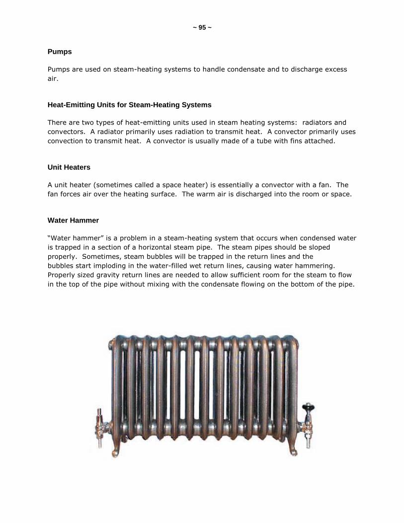
~ 95 ~
Pumps
Pumps are used on steam-heating systems to handle condensate and to discharge excess
air.
Heat-Emitting Units for Steam-Heating Systems
There are two types of heat-emitting units used in steam heating systems: radiators and
convectors. A radiator primarily uses radiation to transmit heat. A convector primarily uses
convection to transmit heat. A convector is usually made of a tube with fins attached.
Unit Heaters
A unit heater (sometimes called a space heater) is essentially a convector with a fan. The
fan forces air over the heating surface. The warm air is discharged into the room or space.
Water Hammer
“Water hammer” is a problem in a steam-heating system that occurs when condensed water
is trapped in a section of a horizontal steam pipe. The steam pipes should be sloped
properly. Sometimes, steam bubbles will be trapped in the return lines and the
bubbles start imploding in the water-filled wet return lines, causing water hammering.
Properly sized gravity return lines are needed to allow sufficient room for the steam to flow
in the top of the pipe without mixing with the condensate flowing on the bottom of the pipe.

~ 96 ~
SECTION 18: ELECTRIC HEATING SYSTEMS
There are various types of electric heating systems. They all use electricity to transfer heat
by the following three ways:
radiation;
convection; and
forced air.
Electric Hot Water Systems
There are electric boilers that are used as the main heat source. Electric boilers are
compact and insulated, with heating elements immersed in the water of the boiler. Inside
the compact electric boiler unit are all of the components, including the expansion tank,
pump, valves and controls.
Electric Forced Warm-Air Heating Systems
At an electric forced warm-air heating system, heated air is forced through to the rooms
and spaces of the building by the use of a blower fan and ducts or pipes. They have zero
clearances. They can be installed horizontally or vertically. Inside the electric furnace is at
least one coiled resistance-wire heating element. When there is more than one coil, the
coils are activated sequentially, one by one, to prevent an electrical current overload. There
is a high-temperature control installed in the unit. The furnace is controlled by a
thermostat. A blower fan is installed to force air through the heating elements.
Electrical Radiant Heating Systems
A common type of electrical radiant heating system is one that has a cable embedded in the
floor, wall or ceiling. The heat that is created by the cable is transferred to the occupants
and surfaces in the room by low-intensity radiation. There are three types of radiant panel
systems:
radiant floor panel systems;
radiant wall panel systems; and
radiant ceiling panel systems.
Electric Baseboard Heating Systems
Electric baseboard heating units are usually installed at the floor level and around the
outside perimeter of each room or space of the building, particularly below windows.
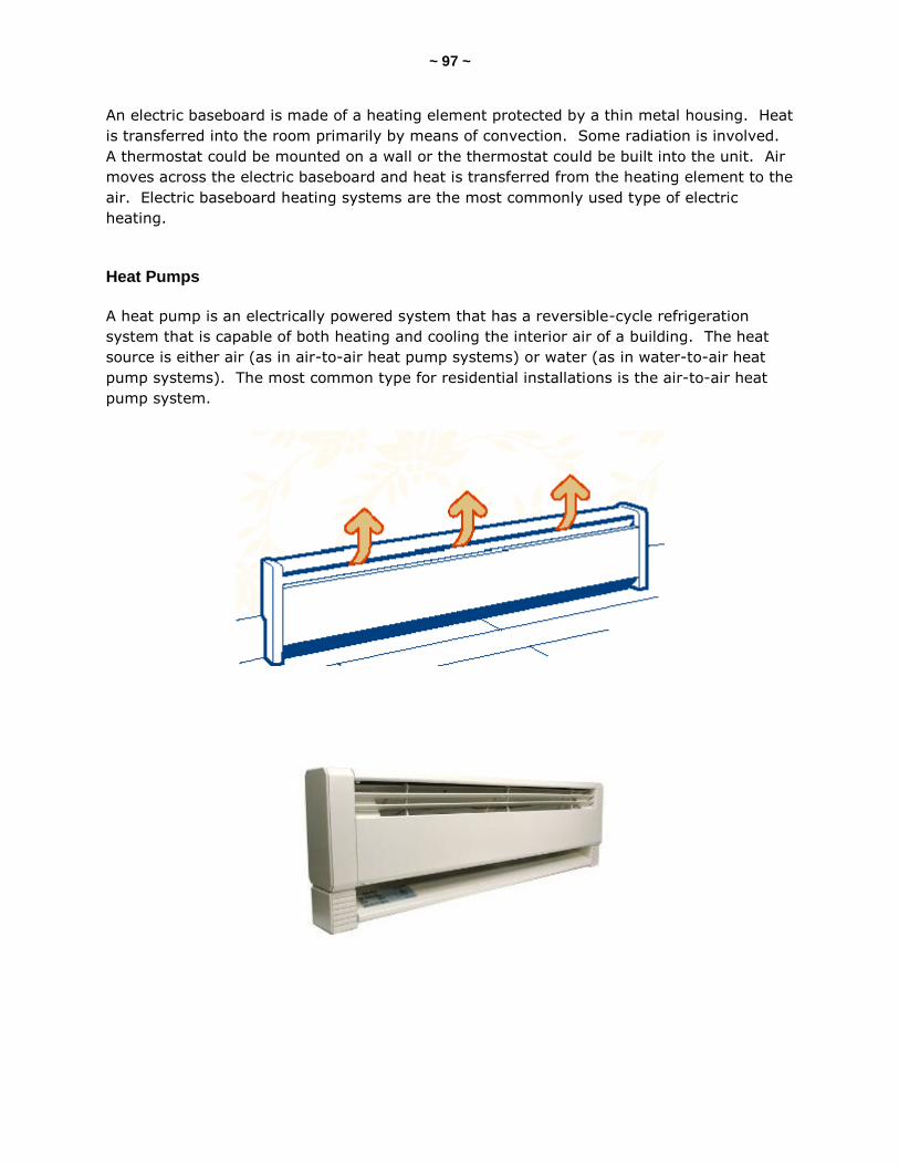
~ 97 ~
An electric baseboard is made of a heating element protected by a thin metal housing. Heat
is transferred into the room primarily by means of convection. Some radiation is involved.
A thermostat could be mounted on a wall or the thermostat could be built into the unit. Air
moves across the electric baseboard and heat is transferred from the heating element to the
air. Electric baseboard heating systems are the most commonly used type of electric
heating.
Heat Pumps
A heat pump is an electrically powered system that has a reversible-cycle refrigeration
system that is capable of both heating and cooling the interior air of a building. The heat
source is either air (as in air-to-air heat pump systems) or water (as in water-to-air heat
pump systems). The most common type for residential installations is the air-to-air heat
pump system.
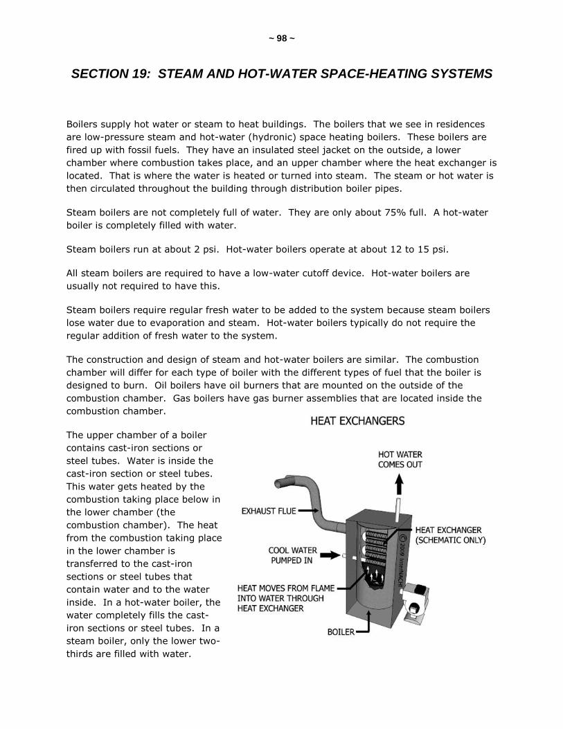
~ 98 ~
SECTION 19: STEAM AND HOT-WATER SPACE-HEATING SYSTEMS
Boilers supply hot water or steam to heat buildings. The boilers that we see in residences
are low-pressure steam and hot-water (hydronic) space heating boilers. These boilers are
fired up with fossil fuels. They have an insulated steel jacket on the outside, a lower
chamber where combustion takes place, and an upper chamber where the heat exchanger is
located. That is where the water is heated or turned into steam. The steam or hot water is
then circulated throughout the building through distribution boiler pipes.
Steam boilers are not completely full of water. They are only about 75% full. A hot-water
boiler is completely filled with water.
Steam boilers run at about 2 psi. Hot-water boilers operate at about 12 to 15 psi.
All steam boilers are required to have a low-water cutoff device. Hot-water boilers are
usually not required to have this.
Steam boilers require regular fresh water to be added to the system because steam boilers
lose water due to evaporation and steam. Hot-water boilers typically do not require the
regular addition of fresh water to the system.
The construction and design of steam and hot-water boilers are similar. The combustion
chamber will differ for each type of boiler with the different types of fuel that the boiler is
designed to burn. Oil boilers have oil burners that are mounted on the outside of the
combustion chamber. Gas boilers have gas burner assemblies that are located inside the
combustion chamber.
The upper chamber of a boiler
contains cast-iron sections or
steel tubes. Water is inside the
cast-iron section or steel tubes.
This water gets heated by the
combustion taking place below in
the lower chamber (the
combustion chamber). The heat
from the combustion taking place
in the lower chamber is
transferred to the cast-iron
sections or steel tubes that
contain water and to the water
inside. In a hot-water boiler, the
water completely fills the cast-
iron sections or steel tubes. In a
steam boiler, only the lower two-
thirds are filled with water.
~ 99 ~
In a steam boiler, water is heated rapidly to the point when steam is created. That hot
steam rises up through the distribution pipes and supplies heat to the building.
Boiler Efficiency
Boiler efficiency is based on several factors, including the type of fuel used, the method of
firing, and the control settings. The efficiency rating of a boiler is measured by its annual
fuel utilization efficiency (AFUE). The minimum established by the U.S. government for
boilers is 78%. Mid-efficiency boilers have a range of 78 to 82%. High-efficiency
(condensing) boilers range from 88 to 97%. Conventional (non-condensing) steam and
hot-water space heating boilers have AFUE ranges of around 60 to 65%.
Describing Boilers
Low-pressure boilers and hot-water space heaters can be identified and described in variety
of ways. Such boilers can be categorized by:
cast iron or steel;
type of exchanger;
type of fuel used; and
one or two pipes.
Most boilers are made of cast iron or steel. A few are aluminum. Cast-iron boilers typically
last longer because cast iron resists corrosion better than steel. The heat exchanger of
many boilers is made up of sections of cast-iron pieces that are joined together either in
layers horizontally (“sandwiched” or “pancaked” together) or vertically joined together, like
a tight stack of dominos. The water moves from section to section in a zigzag pattern and
gets heated.
For boilers with a tubular heat exchanger, the water either circulates within the tubes and
gets heated by the combustion gases, or the water circulates around the tubes that contain
the hot combustion gases.
A hot-water copper-fin tube operates slightly differently than cast-iron and steel boilers.
Water flows across the fins and gets heated very quickly.
Boilers can be fired by various fuels, including electricity. The most common boilers tend to
be gas-fired or oil-fired.
Steam Boiler Valves and Controls
Boilers used for steam heat have a variety of valves and controls. They can be divided in
two broad categories: safety and measurement; and controlling.
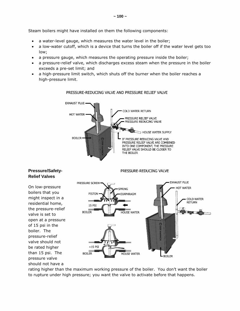
~ 100 ~
Steam boilers might have installed on them the following components:
a water-level gauge, which measures the water level in the boiler;
a low-water cutoff, which is a device that turns the boiler off if the water level gets too
low;
a pressure gauge, which measures the operating pressure inside the boiler;
a pressure-relief valve, which discharges excess steam when the pressure in the boiler
exceeds a pre-set limit; and
a high-pressure limit switch, which shuts off the burner when the boiler reaches a
high-pressure limit.
Pressure/Safety-
Relief Valves
On low-pressure
boilers that you
might inspect in a
residential home,
the pressure-relief
valve is set to
open at a pressure
of 15 psi in the
boiler. The
pressure-relief
valve should not
be rated higher
than 15 psi. The
pressure valve
should not have a
rating higher than the maximum working pressure of the boiler. You don’t want the boiler
to rupture under high pressure; you want the valve to activate before that happens.

~ 101 ~
Pressure-relief valves that are installed on a hot-water heating boiler will open under two
conditions:
water thermal conditions; and
steam-pressure conditions.
These relief valves are used to protect against damage to property and injury to people.
These relief valves will start to open up at a set pressure and will open fully at a maximum
pressure.
If temperature limits are reached in the boiler, the valve will start to open. If pressure in
the boiler reaches a limit, the valve opens as a water-relief valve discharges a small amount
of water that has expanded inside the boiler.
If both water and steam are present in a hot-water boiler, there is a problem with the
boiler. The boiler is reaching steam-forming temperatures and steam pressure is being
created. The relief valve will open under this steam-pressure condition. It acts as a steam-
pressure relief valve under this condition in the boiler. These safety-relief valves open
under excessive water-pressure conditions and under excessive steam-pressure conditions.
Pressure-Reducing Valve
Pressure-reducing valves are sometimes referred to as boilder feed valves. Pressure-
reducing valves are designed to fill a hot-water boiler automatically if the pressure in the
system drops below the setting of the valve. Its primary function is to keep the system
automatically filled with water at the desired operating pressure. Older systems have
valves that are operated manually. The valve is usually installed on the cold-water supply
line.
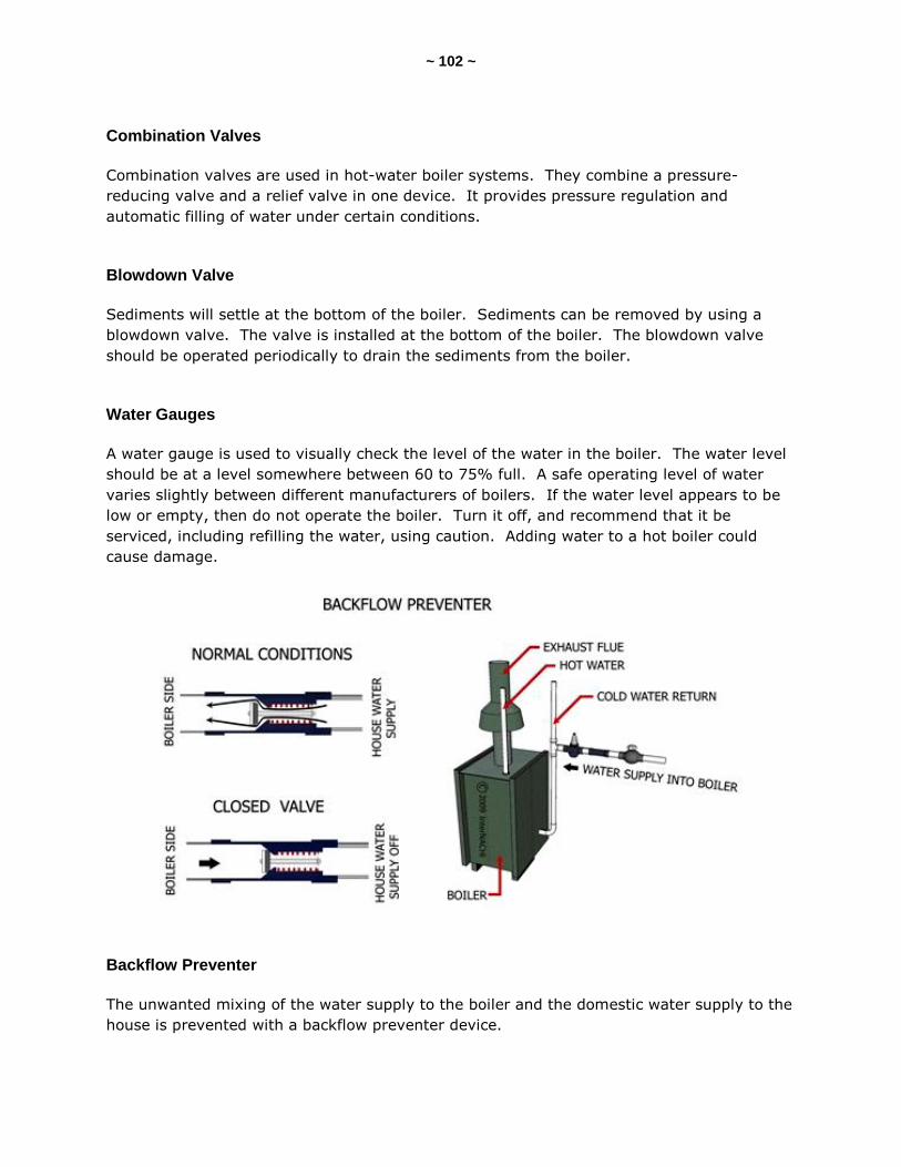
~ 102 ~
Combination Valves
Combination valves are used in hot-water boiler systems. They combine a pressure-
reducing valve and a relief valve in one device. It provides pressure regulation and
automatic filling of water under certain conditions.
Blowdown Valve
Sediments will settle at the bottom of the boiler. Sediments can be removed by using a
blowdown valve. The valve is installed at the bottom of the boiler. The blowdown valve
should be operated periodically to drain the sediments from the boiler.
Water Gauges
A water gauge is used to visually check the level of the water in the boiler. The water level
should be at a level somewhere between 60 to 75% full. A safe operating level of water
varies slightly between different manufacturers of boilers. If the water level appears to be
low or empty, then do not operate the boiler. Turn it off, and recommend that it be
serviced, including refilling the water, using caution. Adding water to a hot boiler could
cause damage.
Backflow Preventer
The unwanted mixing of the water supply to the boiler and the domestic water supply to the
house is prevented with a backflow preventer device.
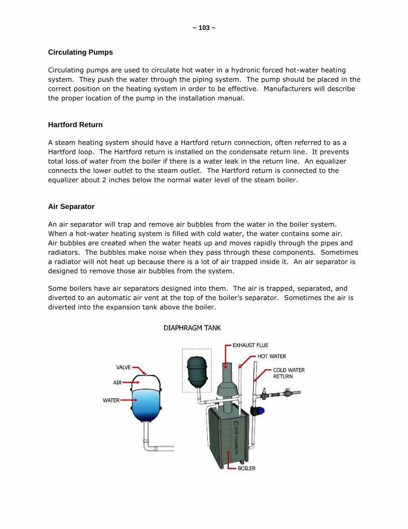
~ 103 ~
Circulating Pumps
Circulating pumps are used to circulate hot water in a hydronic forced hot-water heating
system. They push the water through the piping system. The pump should be placed in the
correct position on the heating system in order to be effective. Manufacturers will describe
the proper location of the pump in the installation manual.
Hartford Return
A steam heating system should have a Hartford return connection, often referred to as a
Hartford loop. The Hartford return is installed on the condensate return line. It prevents
total loss of water from the boiler if there is a water leak in the return line. An equalizer
connects the lower outlet to the steam outlet. The Hartford return is connected to the
equalizer about 2 inches below the normal water level of the steam boiler.
Air Separator
An air separator will trap and remove air bubbles from the water in the boiler system.
When a hot-water heating system is filled with cold water, the water contains some air.
Air bubbles are created when the water heats up and moves rapidly through the pipes and
radiators. The bubbles make noise when they pass through these components. Sometimes
a radiator will not heat up because there is a lot of air trapped inside it. An air separator is
designed to remove those air bubbles from the system.
Some boilers have air separators designed into them. The air is trapped, separated, and
diverted to an automatic air vent at the top of the boiler’s separator. Sometimes the air is
diverted into the expansion tank above the boiler.
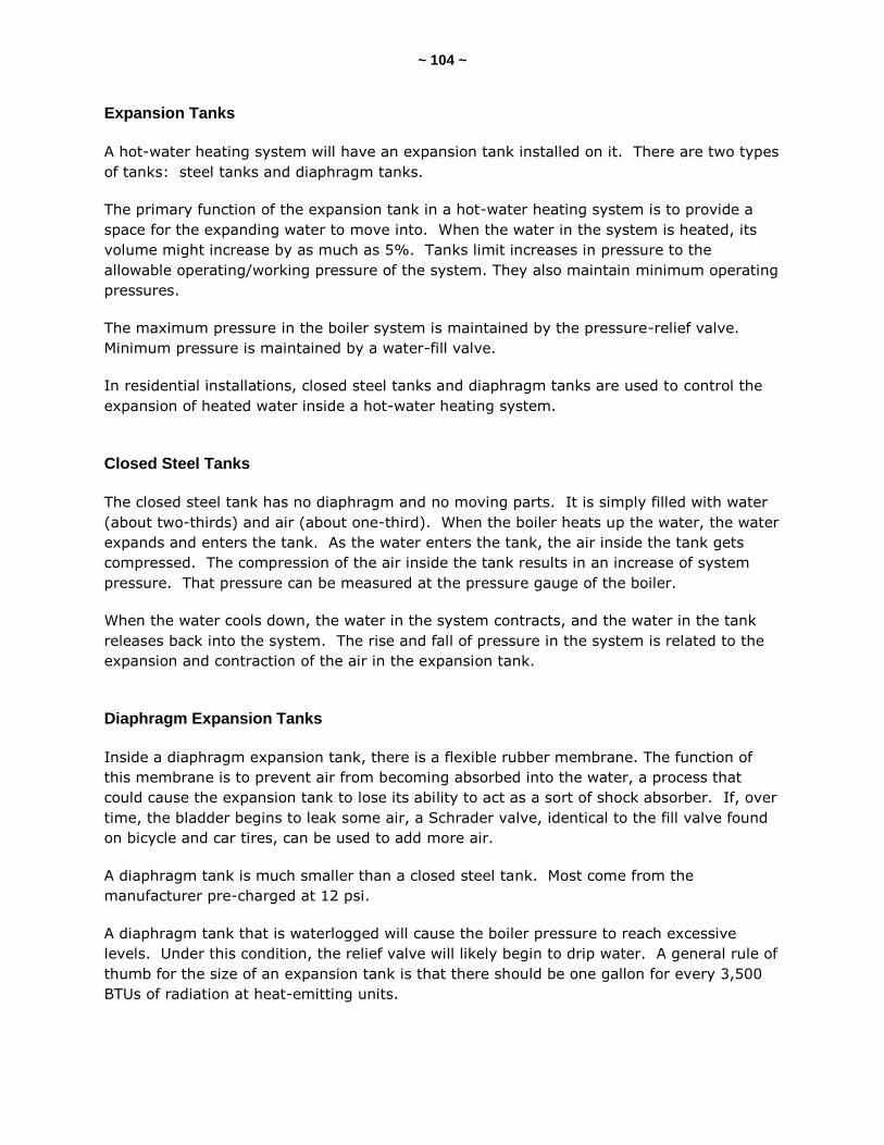
~ 104 ~
Expansion Tanks
A hot-water heating system will have an expansion tank installed on it. There are two types
of tanks: steel tanks and diaphragm tanks.
The primary function of the expansion tank in a hot-water heating system is to provide a
space for the expanding water to move into. When the water in the system is heated, its
volume might increase by as much as 5%. Tanks limit increases in pressure to the
allowable operating/working pressure of the system. They also maintain minimum operating
pressures.
The maximum pressure in the boiler system is maintained by the pressure-relief valve.
Minimum pressure is maintained by a water-fill valve.
In residential installations, closed steel tanks and diaphragm tanks are used to control the
expansion of heated water inside a hot-water heating system.
Closed Steel Tanks
The closed steel tank has no diaphragm and no moving parts. It is simply filled with water
(about two-thirds) and air (about one-third). When the boiler heats up the water, the water
expands and enters the tank. As the water enters the tank, the air inside the tank gets
compressed. The compression of the air inside the tank results in an increase of system
pressure. That pressure can be measured at the pressure gauge of the boiler.
When the water cools down, the water in the system contracts, and the water in the tank
releases back into the system. The rise and fall of pressure in the system is related to the
expansion and contraction of the air in the expansion tank.
Diaphragm Expansion Tanks
Inside a diaphragm expansion tank, there is a flexible rubber membrane. The function of
this membrane is to prevent air from becoming absorbed into the water, a process that
could cause the expansion tank to lose its ability to act as a sort of shock absorber. If, over
time, the bladder begins to leak some air, a Schrader valve, identical to the fill valve found
on bicycle and car tires, can be used to add more air.
A diaphragm tank is much smaller than a closed steel tank. Most come from the
manufacturer pre-charged at 12 psi.
A diaphragm tank that is waterlogged will cause the boiler pressure to reach excessive
levels. Under this condition, the relief valve will likely begin to drip water. A general rule of
thumb for the size of an expansion tank is that there should be one gallon for every 3,500
BTUs of radiation at heat-emitting units.

~ 105 ~
Water-Tempering Valves
Water-tempering valves are used at hot-water heating systems that heat domestic hot
water at the boiler. The water-tempering valve mixes hot and cold water to the desired,
safe temperature, thus preventing scalding at the fixtures. Without a water-tempering
valve, the scalding hot water that is produced at the boiler would be supplied directly from
the boiler to the fixtures. These valves are installed at tankless heaters, boiler coils, water
heaters, and space heating systems.
Balancing Valve
A balancing valve is used to balance a heating system. You can also use the valve to
determine how much water is flowing through the valve.
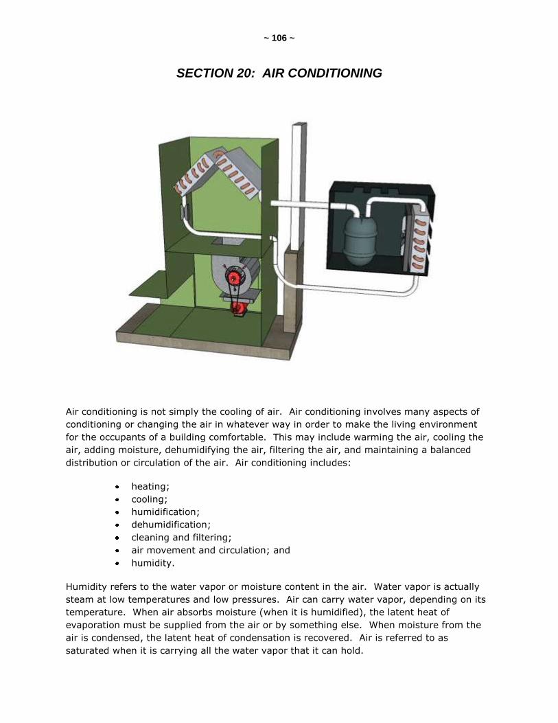
~ 106 ~
SECTION 20: AIR CONDITIONING
Air conditioning is not simply the cooling of air. Air conditioning involves many aspects of
conditioning or changing the air in whatever way in order to make the living environment
for the occupants of a building comfortable. This may include warming the air, cooling the
air, adding moisture, dehumidifying the air, filtering the air, and maintaining a balanced
distribution or circulation of the air. Air conditioning includes:
heating;
cooling;
humidification;
dehumidification;
cleaning and filtering;
air movement and circulation; and
humidity.
Humidity refers to the water vapor or moisture content in the air. Water vapor is actually
steam at low temperatures and low pressures. Air can carry water vapor, depending on its
temperature. When air absorbs moisture (when it is humidified), the latent heat of
evaporation must be supplied from the air or by something else. When moisture from the
air is condensed, the latent heat of condensation is recovered. Air is referred to as
saturated when it is carrying all the water vapor that it can hold.
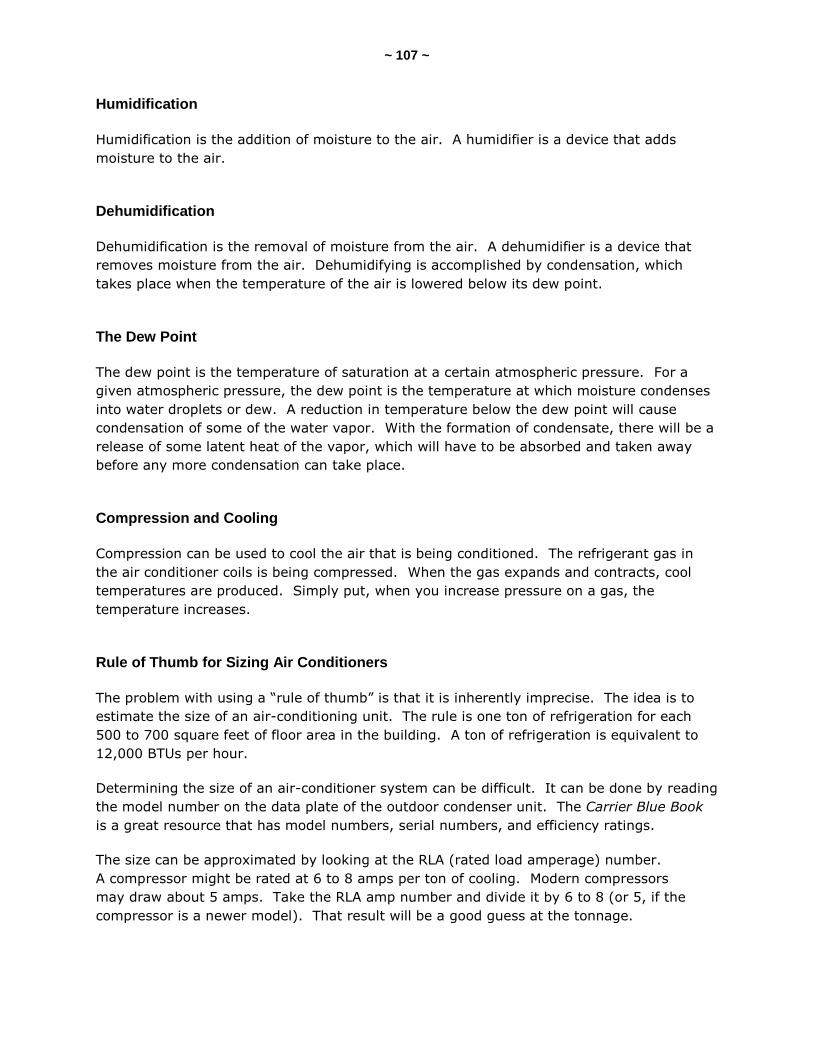
~ 107 ~
Humidification
Humidification is the addition of moisture to the air. A humidifier is a device that adds
moisture to the air.
Dehumidification
Dehumidification is the removal of moisture from the air. A dehumidifier is a device that
removes moisture from the air. Dehumidifying is accomplished by condensation, which
takes place when the temperature of the air is lowered below its dew point.
The Dew Point
The dew point is the temperature of saturation at a certain atmospheric pressure. For a
given atmospheric pressure, the dew point is the temperature at which moisture condenses
into water droplets or dew. A reduction in temperature below the dew point will cause
condensation of some of the water vapor. With the formation of condensate, there will be a
release of some latent heat of the vapor, which will have to be absorbed and taken away
before any more condensation can take place.
Compression and Cooling
Compression can be used to cool the air that is being conditioned. The refrigerant gas in
the air conditioner coils is being compressed. When the gas expands and contracts, cool
temperatures are produced. Simply put, when you increase pressure on a gas, the
temperature increases.
Rule of Thumb for Sizing Air Conditioners
The problem with using a “rule of thumb” is that it is inherently imprecise. The idea is to
estimate the size of an air-conditioning unit. The rule is one ton of refrigeration for each
500 to 700 square feet of floor area in the building. A ton of refrigeration is equivalent to
12,000 BTUs per hour.
Determining the size of an air-conditioner system can be difficult. It can be done by reading
the model number on the data plate of the outdoor condenser unit. The Carrier Blue Book
is a great resource that has model numbers, serial numbers, and efficiency ratings.
The size can be approximated by looking at the RLA (rated load amperage) number.
A compressor might be rated at 6 to 8 amps per ton of cooling. Modern compressors
may draw about 5 amps. Take the RLA amp number and divide it by 6 to 8 (or 5, if the
compressor is a newer model). That result will be a good guess at the tonnage.
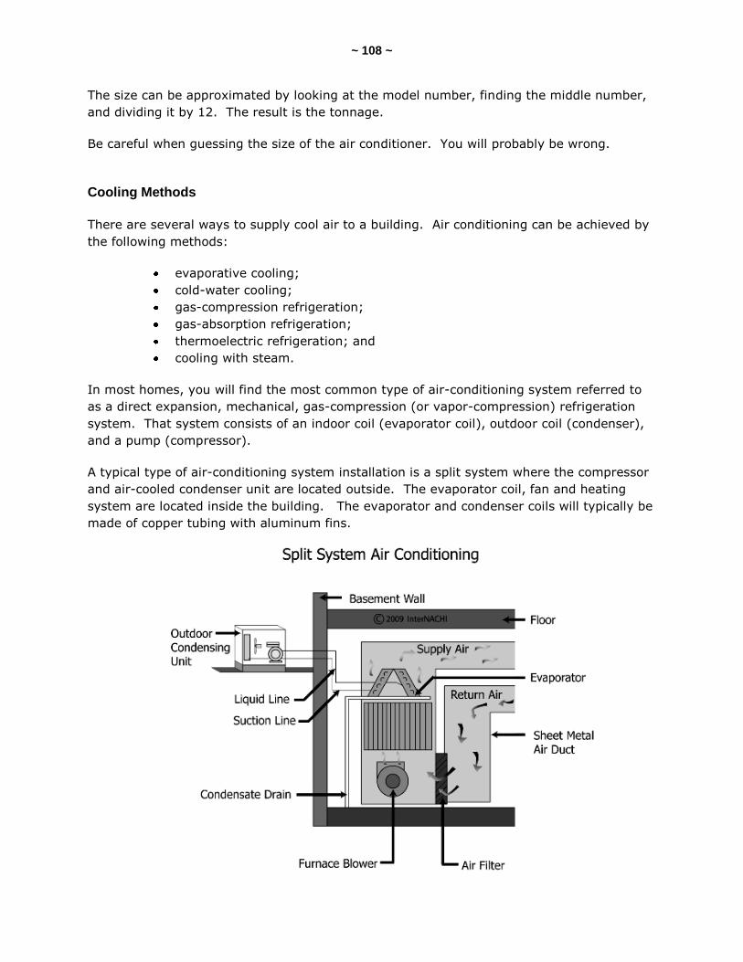
~ 108 ~
The size can be approximated by looking at the model number, finding the middle number,
and dividing it by 12. The result is the tonnage.
Be careful when guessing the size of the air conditioner. You will probably be wrong.
Cooling Methods
There are several ways to supply cool air to a building. Air conditioning can be achieved by
the following methods:
evaporative cooling;
cold-water cooling;
gas-compression refrigeration;
gas-absorption refrigeration;
thermoelectric refrigeration; and
cooling with steam.
In most homes, you will find the most common type of air-conditioning system referred to
as a direct expansion, mechanical, gas-compression (or vapor-compression) refrigeration
system. That system consists of an indoor coil (evaporator coil), outdoor coil (condenser),
and a pump (compressor).
A typical type of air-conditioning system installation is a split system where the compressor
and air-cooled condenser unit are located outside. The evaporator coil, fan and heating
system are located inside the building. The evaporator and condenser coils will typically be
made of copper tubing with aluminum fins.
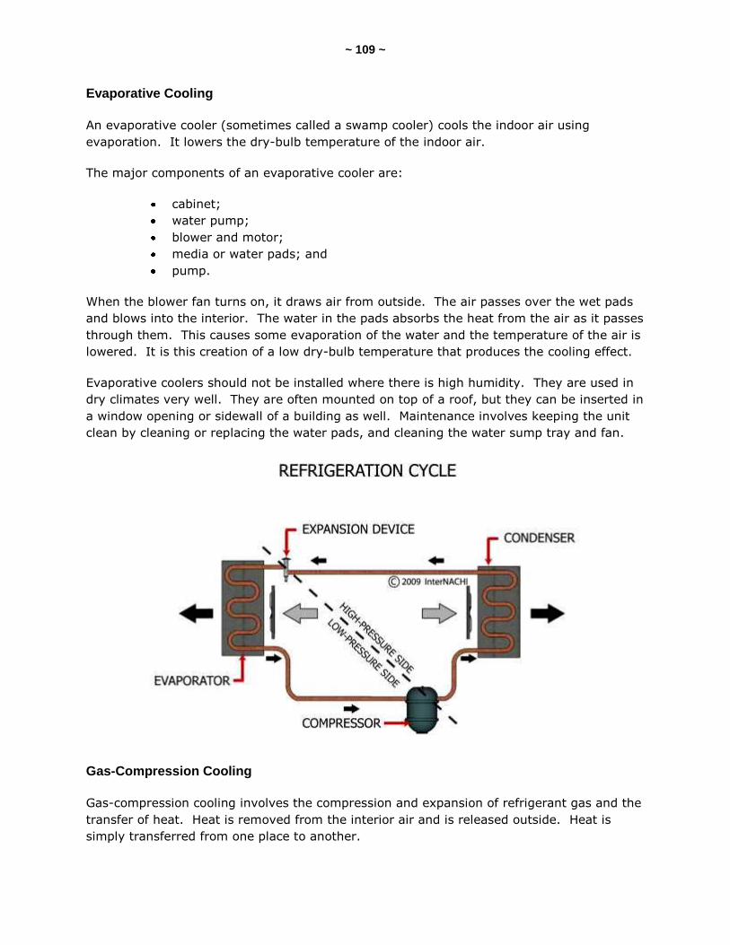
~ 109 ~
Evaporative Cooling
An evaporative cooler (sometimes called a swamp cooler) cools the indoor air using
evaporation. It lowers the dry-bulb temperature of the indoor air.
The major components of an evaporative cooler are:
cabinet;
water pump;
blower and motor;
media or water pads; and
pump.
When the blower fan turns on, it draws air from outside. The air passes over the wet pads
and blows into the interior. The water in the pads absorbs the heat from the air as it passes
through them. This causes some evaporation of the water and the temperature of the air is
lowered. It is this creation of a low dry-bulb temperature that produces the cooling effect.
Evaporative coolers should not be installed where there is high humidity. They are used in
dry climates very well. They are often mounted on top of a roof, but they can be inserted in
a window opening or sidewall of a building as well. Maintenance involves keeping the unit
clean by cleaning or replacing the water pads, and cleaning the water sump tray and fan.
Gas-Compression Cooling
Gas-compression cooling involves the compression and expansion of refrigerant gas and the
transfer of heat. Heat is removed from the interior air and is released outside. Heat is
simply transferred from one place to another.
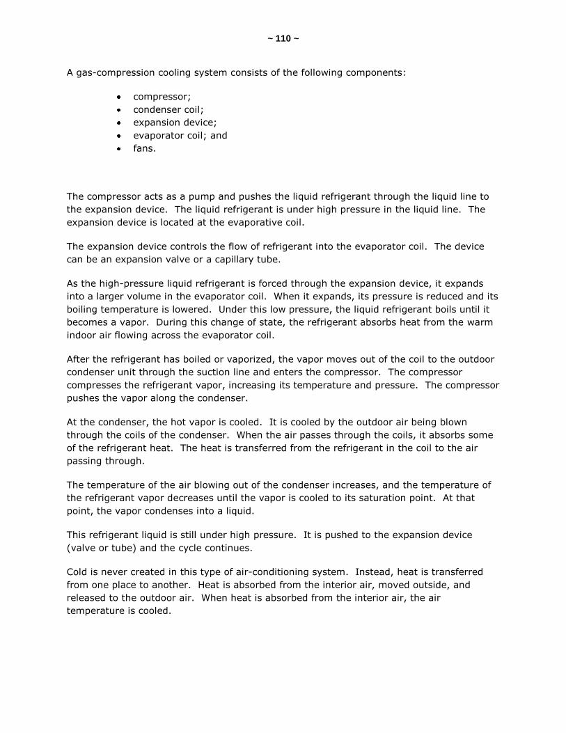
~ 110 ~
A gas-compression cooling system consists of the following components:
compressor;
condenser coil;
expansion device;
evaporator coil; and
fans.
The compressor acts as a pump and pushes the liquid refrigerant through the liquid line to
the expansion device. The liquid refrigerant is under high pressure in the liquid line. The
expansion device is located at the evaporative coil.
The expansion device controls the flow of refrigerant into the evaporator coil. The device
can be an expansion valve or a capillary tube.
As the high-pressure liquid refrigerant is forced through the expansion device, it expands
into a larger volume in the evaporator coil. When it expands, its pressure is reduced and its
boiling temperature is lowered. Under this low pressure, the liquid refrigerant boils until it
becomes a vapor. During this change of state, the refrigerant absorbs heat from the warm
indoor air flowing across the evaporator coil.
After the refrigerant has boiled or vaporized, the vapor moves out of the coil to the outdoor
condenser unit through the suction line and enters the compressor. The compressor
compresses the refrigerant vapor, increasing its temperature and pressure. The compressor
pushes the vapor along the condenser.
At the condenser, the hot vapor is cooled. It is cooled by the outdoor air being blown
through the coils of the condenser. When the air passes through the coils, it absorbs some
of the refrigerant heat. The heat is transferred from the refrigerant in the coil to the air
passing through.
The temperature of the air blowing out of the condenser increases, and the temperature of
the refrigerant vapor decreases until the vapor is cooled to its saturation point. At that
point, the vapor condenses into a liquid.
This refrigerant liquid is still under high pressure. It is pushed to the expansion device
(valve or tube) and the cycle continues.
Cold is never created in this type of air-conditioning system. Instead, heat is transferred
from one place to another. Heat is absorbed from the interior air, moved outside, and
released to the outdoor air. When heat is absorbed from the interior air, the air
temperature is cooled.
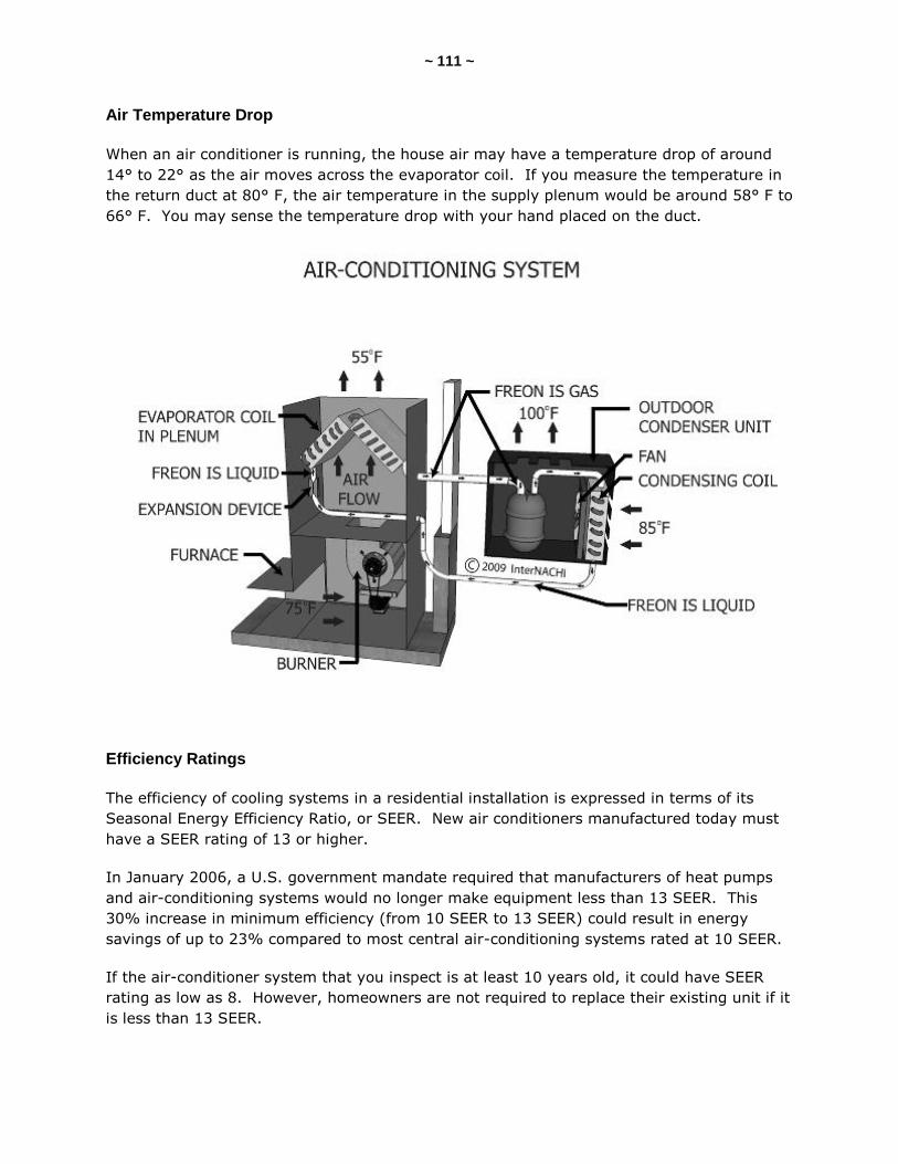
~ 111 ~
Air Temperature Drop
When an air conditioner is running, the house air may have a temperature drop of around
14° to 22° as the air moves across the evaporator coil. If you measure the temperature in
the return duct at 80° F, the air temperature in the supply plenum would be around 58° F to
66° F. You may sense the temperature drop with your hand placed on the duct.
Efficiency Ratings
The efficiency of cooling systems in a residential installation is expressed in terms of its
Seasonal Energy Efficiency Ratio, or SEER. New air conditioners manufactured today must
have a SEER rating of 13 or higher.
In January 2006, a U.S. government mandate required that manufacturers of heat pumps
and air-conditioning systems would no longer make equipment less than 13 SEER. This
30% increase in minimum efficiency (from 10 SEER to 13 SEER) could result in energy
savings of up to 23% compared to most central air-conditioning systems rated at 10 SEER.
If the air-conditioner system that you inspect is at least 10 years old, it could have SEER
rating as low as 8. However, homeowners are not required to replace their existing unit if it
is less than 13 SEER.
~ 112 ~
Central Air-Conditioner or Heat-Pump Cooling Efficiency (SEER) based on manufactured
date:
1970 and earlier: SEER = 6
1971 to 1996: SEER = 9.5
1997 to 2002: SEER = 10.75
2003 to 2007: SEER = 11.2
2008 and later: SEER = 13
Heat-Pump Heating Efficiency (HSPF):
1970 and earlier: HSPF = 5
1971 to 2007: HSPF = 5.5
2008 and later: HSPF = 7.7
Room (Window) Air-Conditioner Cooling Efficiency (EER):
1972 and earlier: EER = 6
1973 to 1994: EER = 6
1995 to 1998: EER = 9
1999 to 2001: EER = 9
2002 and later EER = 9.75

~ 113 ~
Compressor
A compressor is a pump. It is located inside the outdoor condenser unit. It receives the
low-pressure refrigerant vapor through the suction line, and compresses or squeezes it into
a smaller volume at a higher pressure. The compressor makes the pressure difference in
the system, and it pushes or forces the refrigerant to flow around the system.
There are different types of compressors. They are reciprocating or piston, scroll, rotary,
centrifugal, and screw-type. The scroll compressor is a relatively new design type.
Inspection Restrictions
Compressors should not be operated when it’s below 65° F outside. Compressors should
not be operated when the electricity has been turned on for less than 24 hours. Damaging
the compressor is possible. Oil may be mixed with the refrigerant in the base of the
compressor.
Compressor Heater
Many air-conditioning systems have a heater (a sump heater or crankcase heater) installed
on the bottom of the compressor. The heater keeps the oil at the base of the compressor
warm enough to boil off the refrigerant. The heater may be internal (not visible), or visible
on the outside as a ring wrapped around the compressor base. If the electricity has been
turned off to the system, it may take 12 to 24 hours for the heater to warm up the oil
sufficiently to boil off the refrigerant.
~ 114 ~
Condenser
In a typical air-conditioning split system, the condenser unit (or outdoor coil) is located
outside. A condenser condenses or liquefies gas by cooling it. When the condenser is
running, hot refrigerant gas coming from the compressor enters the condenser coil at the
top. As it passes down through the condenser coil, it cools. The compressor is located
inside the condenser unit.
The condenser can be a plain tube design, finned tube, or plate-type. It can be a series-
pass or parallel-pass type. Condenser units can be air-cooled (the most common for
residential installations), water-cooled, or a combination of the two.
An air-cooled condenser is made up of a coil that air blows across to cool the hot gas that's
passing through the coil. There is a fan inside the condenser that pushes the air through
the coil. Heat is transferred from the hot gases that are moving in the coil to the air
passing through the coil.
If you put your hand in the path of the air blowing out of an operating condenser, it will feel
warm.
Air-cooled condensers must be maintained, kept clean and free from debris and damage.
The fins on the condenser coils can be easily damaged and bent. Damaged and bent fins
can block the air flow through the condenser coil. A fin comb is a device that can straighten
the fins back into their original position.
Evaporator
An evaporator is sometimes called an evaporator coil, cooling coil and indoor blower coil. In
a typical residential air-conditioning system, the evaporator absorbs the heat energy from
the air passing through it. It transfers the heat energy from the passing air to the
refrigerant moving inside it. As the liquid refrigerant absorbs the heat, it is boiled off or
evaporated as it moves through the evaporator. The house's air temperature drops as it
passes through the coil, pushed by the blower fan.
Evaporators are usually made of copper tubing with closely spaced aluminum fins. There
are about 14 aluminum fins per inch of copper tubing. This type of finned coil provides very
good surface area for transferring heat. Some coils are made of aluminum tubing, which
does not last as long as copper tubing.
The evaporator coil is sometimes called an A-coil, because some are shaped like the letter
A. Some coils are called slab coils because they appear like a slab tilted at an angle. Coils
have a condensate tray underneath to catch the condensate water draining off the coil.
Similar to the condenser, the evaporator coil must be maintained, and kept clean and free
from dirt, dust and damage.

~ 115 ~
Refrigerant
A refrigerant is a substance that absorbs heat as it expands or vaporizes. A good
refrigerant has a low boiling point and functions with a positive pressure.
The two most commonly used refrigerants in older air-conditioning systems are R-12 (Freon
12) and R-22 (Freon 22). R-12 has a boiling point of -21.8° F at atmospheric pressure.
R-22 has a boiling point of -41.4° F.
R-410A is replacing those older refrigerants because it does not deplete ozone. R-410A can
be recognized by its various trade names, including Genetron AZ20, Dupont Suva and
Puron.
Expansion Device
An expansion device changes the refrigerant from high-pressure, high-temperature liquid to
a low-pressure, low-temperature liquid. It is installed just before the evaporator. There are
two common expansion devices:
capillary tubes; and
thermostatic expansion valves.
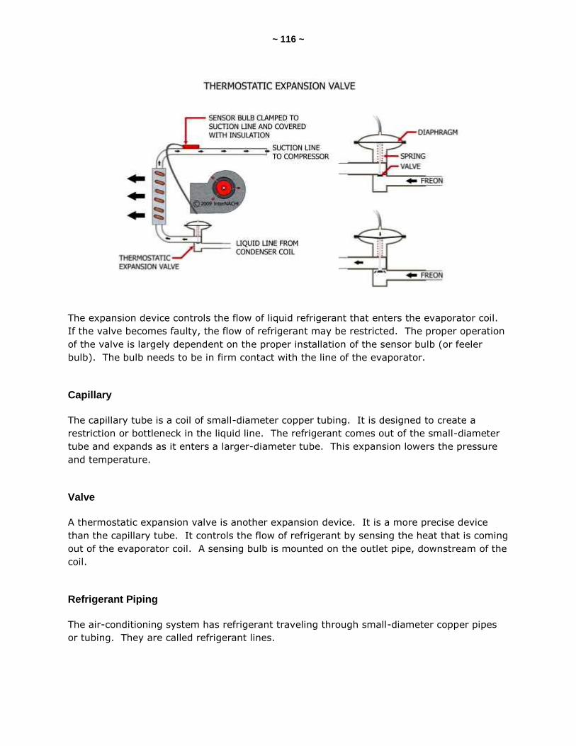
~ 116 ~
The expansion device controls the flow of liquid refrigerant that enters the evaporator coil.
If the valve becomes faulty, the flow of refrigerant may be restricted. The proper operation
of the valve is largely dependent on the proper installation of the sensor bulb (or feeler
bulb). The bulb needs to be in firm contact with the line of the evaporator.
Capillary
The capillary tube is a coil of small-diameter copper tubing. It is designed to create a
restriction or bottleneck in the liquid line. The refrigerant comes out of the small-diameter
tube and expands as it enters a larger-diameter tube. This expansion lowers the pressure
and temperature.
Valve
A thermostatic expansion valve is another expansion device. It is a more precise device
than the capillary tube. It controls the flow of refrigerant by sensing the heat that is coming
out of the evaporator coil. A sensing bulb is mounted on the outlet pipe, downstream of the
coil.
Refrigerant Piping
The air-conditioning system has refrigerant traveling through small-diameter copper pipes
or tubing. They are called refrigerant lines.

~ 117 ~
The suction line is the pipe from the evaporator coil (inside the house) to the compressor
(inside the condenser unit). The suction line carries the vapor (not liquid).
The liquid line is the pipe from the condenser coil (in the condenser unit) to the evaporator.
The liquid line carries the liquid (not the vapor).
All lines should be checked for damage and bent sections. A squeezed or pinched line will
restrict the flow.
The suction and liquid lines should not touch or come in contact with one another. The
warm liquid line would transfer heat to the cooler suction line.
If the evaporator (indoor unit) is installed higher in elevation than the condenser (outdoor
unit), ideally, there should be a slope to the suction line with a fall of ¼-inch per linear foot
toward the condenser (outdoor unit).
Filter-Dryer
A filter removes particles from the liquid refrigerant and from the oil. A dryer (drier or
dehydrator) removes moisture from the refrigerant. The filter-dryer device is a combination
of the two. It is usually installed in the liquid line.
~ 118 ~
QUIZ 8
1. T/F: Gas-compression cooling involves the compression and expansion of refrigerant gas and the transfer of heat.
True
False 2. The efficiency of cooling systems in a residential installation is expressed in terms of its ____.
UFAE
SEAR
SEER 3. The __________ is located inside the outdoor condenser unit and receives the low-pressure refrigerant vapor through the suction line, and compresses or squeezes it into a smaller volume at a higher pressure.
condenser
compressor
evaporator 4. In a typical residential air-conditioning system, the __________ absorbs the heat energy from the air passing through it, and transfers the heat energy from the passing air to the refrigerant moving inside it.
capillary tube
condenser
evaporator
Answer Key to Quiz 8
1. T/F: Gas-compression cooling involves the compression and expansion of refrigerant gas and the transfer of heat. Answer: True
2. The efficiency of cooling systems in a residential installation is expressed in terms of its SEER.
3. The compressor is located inside the outdoor condenser unit and receives the low-pressure refrigerant vapor through the suction line, and compresses or squeezes it into a smaller volume at a higher pressure.
4. In a typical residential air-conditioning system, the evaporator absorbs the heat energy from the air passing through it, and transfers the heat energy from the passing air to the refrigerant moving inside it.
~ 119 ~
SECTION 21: HEAT PUMPS
A heat pump transfers heat from one place to another. It takes heat from the outdoor air
and brings it to the inside of a building and releases it. With the use of a reversing valve,
the heat pump can also take heat from the indoor air and release it outside. During the
“reversed” cycle, the heat pump operates just like an air-conditioning system. Both the
indoor coil and outdoor coil may act as either an evaporator or a condenser.
Types of Heat Pumps
There are three types of heat pumps used in residential and light commercial installations.
They are:
air-source heat pumps;
ground-source heat pumps; and
water-source heat pumps.
Most heat pumps used in residential and light commercial installations are split-system heat
pumps. A split-system heat pump is one that has its components divided, with the
condenser unit (which holds the compressor) installed outside the building, and the
evaporator coil (with the expansion device) located inside the building.
Air-Source Heat Pumps
An air-source heat pump is often called an air-to-air heat pump, which uses the outdoor air
as the source for heat. It uses the outdoor air as the source from which to absorb heat
energy. It takes that heat energy from the outdoor air and transfers it to the interior air of
the building.
The problem with air-source heat pumps occurs when the heat pump is operating in the cold
wintertime and there’s very little heat energy in the outdoor air due to low outdoor
temperatures. And that is the same time that you want the heat pump to produce the most
heat. For this reason, a supplementary radiant heating element is integrated into the
system to be used during those conditions of very cold outdoor temperatures. Air-source
heat pumps work well in areas where the winter temperature does not drop below 30° F for
extended periods of time.
Ground-Source Heat Pump
A ground-source heat pump is sometimes called a geothermal heat pump. A ground-source
heat pump uses the constant temperature of the earth instead of the outdoor air as the heat
source or heat sink, depending on the cycle.

~ 120 ~
A heat-transfer fluid is pushed through a bunch of underground high-strength plastic pipes.
The pipes are often coiled and looped or zig-zagged. Horizontal loops are common in
residential installations. There are horizontal closed-loop, spiral closed-loop, and vertical
closed-loop systems.
A ground-source heat pump can be identified by many different names. Other names of
ground-source heat pumps include:
water-source heat pumps;
well-water heat pumps;
direct-expansion heat pumps;
geothermal heat pumps;
groundwater heat pumps;
earth-coupled heat pumps;
ground-coupled heat pumps; and
open-loop heat pumps.
Water-Source Heat Pump
A water-source heat pump uses water as the heat source (or heat sink). Water is the heat-
transfer medium. The constant temperature of the water source is used instead of the
variable air temperature. The compressor and controls of a water-source heat pump are
identical to those in a ground-source heat pump.
Three Cycles
There are three cycles for a heat pump:
heating cycle;
cooling cycle; and
defrost cycle.
Heating Cycle
In the heating cycle, the refrigerant enters the outdoor coil or condenser unit and moves
through the outdoor coil. Inside the coil, the refrigerant starts out as a liquid in a low-
pressure, low-temperature liquid state. The liquid absorbs heat energy from the outdoor air
passing through the coil. The temperature of the liquid is raised up to its boiling point. The
refrigerant boils into a hot vapor in the coil. The compressor then compresses the gas. The
vapor pressure is increased. The high-pressure, high-temperature vapor is pushed through
the suction line and into the evaporator coil (indoor unit). Heat is transferred or released to
the indoor air (which is much cooler than the hot vapor), passing through the evaporator
(indoor) coil. The cooler air passing through the indoor coil causes the gas to cool and
condense into a liquid, which is still under high pressure.
~ 121 ~
The condensing of the high-pressure, high-temperature refrigerant vapor releases heat
energy to the interior air of the building. The liquid then goes through a pressure-reducing
valve or expansion valve and becomes a low-temperature, low-pressure liquid. This liquid is
now in the liquid line and travels to the outdoor coil or condenser unit, where the cycle
begins again.
The reversing valve allows the refrigerant to flow in opposite directions. The compressor
pumps the refrigerant in a cycle that can be reversed. The indoor coil and the outdoor coil
change their functions based on what cycle is called for.
Cooling Cycle
In the cooling cycle, the valve is reversed, and the compressor pumps the refrigerant in the
direction that results in the heat pump system absorbing heat energy from the interior air
and releasing it outside. The heat pump system operates just like a regular air-conditioning
system.
At the condenser, the hot refrigerant vapor (vapor with a lot of heat energy) is cooled by
the outdoor air being blown through the coils of the condenser. When the air passes
through the coils, it absorbs some of the refrigerant heat. As the passing air absorbs heat,
the vapor in the coil gives off heat. The heat is transferred from the refrigerant in the coil
to the air passing through. Heat that was absorbed from the indoor air is released outside.
Defrost Cycle
When a heat pump is operating in the heating mode or heat cycle, the outdoor air is
relatively cool and the outdoor coil acts as an evaporator. Under certain conditions of
temperature and relative humidity, frost might form on the surface of the outdoor coil. The
layer of frost will interfere with the operation of the heat pump by making the pump work
harder and, therefore, inefficiently. The frost must be removed. A heat pump has a cycle
called a defrost cycle, which removes the frost from the outdoor coil.
A heat pump unit will defrost regularly when frost conditions occur. The defrost cycle
should be long enough to melt the ice, and short enough to be energy-efficient.
In the defrost cycle, the heat pump is automatically operated in reverse, for a moment, in
the cooling cycle. This action temporarily warms up the outdoor coil and melts the frost
from the coil. In this defrost cycle, the outdoor fan is prevented from turning on when the
heat pump switches over, and the temperature rise of the outdoor coil is accelerated and
increased.
The heat pump will operate in the defrost cycle until the outdoor coil temperature reaches
around 57° F. The time it takes to melt and remove accumulated frost from an outdoor coil
will vary, depending on the amount of frost and the internal timing device of the system.
~ 122 ~
Interior Heating Element
During this defrost cycle with older heat pumps, the indoor unit might be operating with the
fan blowing cool air. To prevent cool air from being produced and distributed inside the
house, an electric heating element can be installed and engaged at the same time as the
defrost cycle. In defrost mode, this heating element will automatically turn on, or the
interior blower fan will turn off. The heating component is wired up to the second stage of
a two-stage thermostat.
Compressor
The compressor gets the refrigerant vapor at low pressure and compresses or squeezes it
into a high-pressure, high-temperature vapor. Then the compressor pushes the vapor to
one of the coils, depending on the heating or cooling cycle.
The Typical Defrost Cycle
The components that make up the defrost cycle system include a thermostat, a timer and a
relay. There is a special thermostat or sensor of the defrost cycle system, often referred to
as the frost thermostat. It is located on the bottom of the outdoor coil where it can detect
the temperature of the coil.
When the outdoor coil temperature drops to around 32° F, the thermostat closes the circuit
and makes the system respond. This causes an internal timer to start. Many heat pumps
have a generic timer that energizes the defrost relays at certain time intervals. Some
generic timers will energize the defrost cycle every 30, 60 and 90 minutes.
The defrost relays turn on the compressor, switch the reversing valve of the heat pump,
turn on the interior electric heating element, and stop the fan at the outdoor coil from
spinning. The unit is now in the defrost cycle.
The unit remains in the defrost cycle (or cooling cycle) until the thermostat on the bottom of
the outdoor coil senses that the outdoor coil temperature has reached about 57° F. At that
temperature, the outdoor coil should be free of frost. The frost thermostat opens the
circuit, stops the timer, and then the defrost cycle stops, the internal heater turns off, the
valve reverses, and the unit returns to the heating cycle. A typical defrost cycle might run
from 30 seconds to a few minutes. The defrost cycles should repeat regularly at timed
intervals. An inspector should not observe a rapid cycling of the defrost operation.
In summary, certain conditions can force a heat pump into a defrost cycle (or cooling cycle)
where the fan in the outdoor coil is stopped, the indoor fan is stopped or electric heat is
turned on, and the frost melts and is removed from the outdoor coils. When the frost
thermostat is satisfied (or a certain pre-set time period elapses), the outdoor fan comes
back on, and the heat pump goes back into the heating cycle.

~ 123 ~
One problem of many older heat-pump systems is that the unit will operate in the defrost
cycle regardless of whether ice is present. On these systems, if it’s cold outside, the defrost
cycle might turn on when it is not needed.
If the defrost cycle is not functioning properly, the outdoor coil will appear like a big block of
ice, making the unit non-functional. Damage could result if the heat pump operates without
a functional, normal-operating defrost cycle.
Causes of Frost
There are many reasons why an inspector might find frost and ice stuck on an outdoor coil
of a heat pump that is not properly defrosting. The cause of the frost and ice problem may
include:
a bad reversing valve;
a damaged outdoor coil;
a wiring problem;
a bad thermostat;
a leak in the refrigerant;
a dirty outdoor coil covered with grass, dirt, debris and/or pet hair;
a fan that won’t turn on;
a fan installed backwards with the blades running in the wrong direction;
a motor operating in the incorrect direction; or
a replacement fan motor spinning at a very low rpm.
Diagnosing apparent problems with the defrost cycle of a heat pump is beyond the scope of
a home inspection.
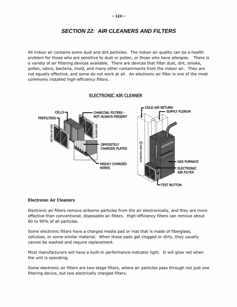
~ 124 ~
SECTION 22: AIR CLEANERS AND FILTERS
All indoor air contains some dust and dirt particles. The indoor air quality can be a health
problem for those who are sensitive to dust or pollen, or those who have allergies. There is
a variety of air filtering devices available. There are devices that filter dust, dirt, smoke,
pollen, odors, bacteria, mold, and many other contaminants from the indoor air. They are
not equally effective, and some do not work at all. An electronic air filter is one of the most
commonly installed high-efficiency filters.
Electronic Air Cleaners
Electronic air filters remove airborne particles from the air electronically, and they are more
effective than conventional, disposable air filters. High-efficiency filters can remove about
80 to 90% of all particles.
Some electronic filters have a charged media pad or mat that is made of fiberglass,
cellulose, or some similar material. When these pads get clogged or dirty, they usually
cannot be washed and require replacement.
Most manufacturers will have a built-in performance-indicator light. It will glow red when
the unit is operating.
Some electronic air filters are two-stage filters, where air particles pass through not just one
filtering device, but two electrically charged filters.
~ 125 ~
There is typically a permanent screen or pre-filtering device. This first filter catches the
larger particles before moving to the first electric filter. In the first filter, the particles
receive an intense positive charge. The positively charged particles are then attracted to
the next filter that has collector plates. These plates are alternately charged with positive
and negative voltages. The particles adhere to the negatively charged plates until the filter
is washed.
Many electronic air filters have a pre-filter (or lint filter) and an after-filter. The after-filter
is installed after the second set of charged collector plates.
Electronic air filters will need to be cleaned once every one to six months. Dishwasher
appliances can be used to clean electronic air filters, but the manufacturer’s
recommendations should be followed. When the filters are put back into place, the filters
must be inserted in the correct direction so that the air flows in the correct direction. There
are usually directional arrows installed on the filter components.
Conventional Air Filters
Conventional air filters are not as efficient as electronic air filters. They are commonly used
in furnaces. They are designed to trap and remove particles and contaminants from the
air. A conventional air filter can be expected to remove about 10% of airborne particles
from the air.
Conventional air filters should be inspected regularly, depending on the manufacturer’s
recommendations. Replacement or disposable air filters should be checked once every
month.
Maintenance
Access to the air filter must be provided. Access must be provided without the need for
special tools or knowledge. When a filter is replaced, it must be of the same dimensions
and size. Filters should be installed and located on the cool-air return-side of the furnace.
A dirty or clogged filter will affect the performance of the heating and cooling system.

~ 126 ~
SECTION 23: HUMIDIFIERS
A humidifier adds moisture to the air primarily by evaporation, by the use of steam, or by
spraying water particles.
A bypass humidifier is a common type of humidifier. It contains an evaporator pad, drum,
and wheel or belt. The pad gets wet and absorbs moisture. Warm air from the supply duct
passes over the wet pad, causes the water to evaporate, and results in adding humidity to
the air.
The operation of a humidifier is controlled by a humidistat that might be mounted in a room
or on a furnace duct.
Many humidifiers use a bypass duct. The bypass duct goes between the supply duct and
the return plenum. A damper should be installed in this bypass duct pipe. The damper is
closed off when the humidifier is not in operation, typically during the summer months.
Location
The common location for a bypass humidifier is on the underside of a horizontal warm-air
supply duct, close to the furnace. Humidifiers are also installed on the sides of furnace
plenums. The warm-air plenum is the most desirable location for a humidifier. The
manufacturer’s recommendations for installation must be followed.

~ 127 ~
Maintenance
Moisture from humidifiers may support microbial growth on wet surfaces where moisture
can condense during cold weather. Humidifiers that discharge small droplets of water from
a reservoir of water are prone to supporting mold growth. Moisture accumulation inside
dirty ductwork creates a suitable environment for mold growth. The reservoir of the
humidifier is usually contaminated, to some degree. Humidifiers should be considered
potential mold growth sources.
All humidifiers use water, so delayed maintenance at a humidifier may cause indoor air-
quality issues for sensitive people. If there is a reservoir of water in the humidifier, then it
needs to be drained and cleaned regularly. Humidifiers need regular maintenance, including
cleaning, and the removal of lime and other residue. Any moisture pads or media need to
be replaced regularly, usually every month while the humidifier is in regular operation.
Levels
Indoor relative humidity (RH) should be between 20% to 40% in the winter, and less than
60% during the rest of the year. Some experts recommend that indoor humidity levels in
general should be between 40% to 60%.
Understanding relative humidity in a building is essential to controlling mold growth.
Relative humidity (RH) is a ratio, expressed as a percentage, of the amount of moisture in
the air to the maximum amount of moisture that the air can hold. Warm air can hold more
moisture than cool air. RH is a factor in determining how much moisture is present in a
room, but it is the available moisture in a substrate, and not the RH of the room’s air, that
determines whether mold can grow.
Many sources recommend maintaining RH in living spaces below 60% to limit microbial
growth. By keeping RH below 60%, one may assume that moisture content in building
materials would be low. However, this assumption may be false because mold grows on
surfaces and in building materials, not in the air. Therefore, it is the RH in the air adjacent
to the surface, and not the ambient RH, which must be lowered in order to control mold
growth. Measuring a room with a relative humidity at or below 60% may mean that the
building materials are fairly dry, but it does not eliminate the possibility of mold growth
because local cold spots and water intrusion may allow the RH of the air adjacent to the
surface to exceed 70%.
Moisture meters are essential for inspectors; they enable them to identify damp areas that
would not be evident otherwise. Infrared thermography cameras are praised for their ability
to detect moisture that is not readily visible.
~ 128 ~
SECTION 24: ELECTRIC FURNACES
Electric furnaces produce heat almost instantly because there are no heat exchangers to
warm up. The heating elements of an electric furnace start producing heat as soon as the
thermostat calls for heat. There is no flame, no combustion, and no venting of gases to
the outside. An electric furnace is 100% efficient. Electric furnaces can be upflow,
downflow or horizontal.
All heating systems require access for service and maintenance, including electric furnaces.
A clearance of 24 to 30 inches should be provided in front of the heating system.
Electric furnaces need very little to no clearance between the furnace and combustibles, but
should still have 24 to 30 inches of open space in front for service and maintenance.
Components
The components of an electric furnace include:
automatic controls;
heating elements;
safety controls;
blower fan and motor; and
air filtering.
Thermostat
A thermostat controls the operation of the furnace. The thermostat senses the air
temperature in the room or space that is being heated. When the thermostat calls for heat,
it sends a signal to the first heating circuit. The heating circuit turns on, and there is
usually a slight delay (15 seconds), and then the blower fan turns on. Another delay (30
seconds) happens before the second heating circuit turns on. All other heating circuits turn
on in a similar fashion.
Heating Elements
An electric heating element has to get very hot -- hotter than its surroundings -- to deliver
the desired level of heat. It may get red-hot or nearly white-hot.
Wires with high heat-resistance are used for heating elements. They include iron,
chromium, nickel, manganese, and alloy wires.
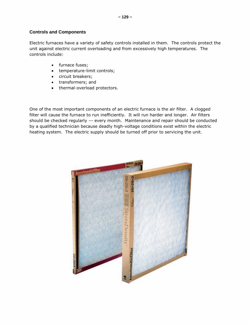
~ 129 ~
Controls and Components
Electric furnaces have a variety of safety controls installed in them. The controls protect the
unit against electric current overloading and from excessively high temperatures. The
controls include:
furnace fuses;
temperature-limit controls;
circuit breakers;
transformers; and
thermal-overload protectors.
One of the most important components of an electric furnace is the air filter. A clogged
filter will cause the furnace to run inefficiently. It will run harder and longer. Air filters
should be checked regularly –- every month. Maintenance and repair should be conducted
by a qualified technician because deadly high-voltage conditions exist within the electric
heating system. The electric supply should be turned off prior to servicing the unit.

~ 130 ~
Conclusion
Now that you’ve finished this book, if you’re an InterNACHI member, be sure to take
InterNACHI’s online “Inspection HVAC Systems” course and final exam, which is a
membership requirement. Once you have successfully completed them, you can download
your Certificate of Completion. This accredited course is worth 12 Continuing Education
credit hours.
After successful completion of the online course and exam, you should be able to perform
an inspection of the HVAC system of a residential property, according to the InterNACHI
Standards of Practice for Performing a General Home Inspection.
Be sure to watch NACHI.TV’s advanced training videos that cover the steps of an HVAC
inspection at www.nachi.or/advancedcourses
~ 131 ~
“Now that you've had a home inspection..."
Only $2.70 each (plus shipping and handling)
116 pages, over 130 illustrations and
high-resolution pictures,
effective cover, professionally edited,
& true-black text
To order, visit:
www.NACHI.org/now
FOUR Steps to Get More Inspection Jobs:
Step 1. Order your books.
Step 2. Staple your home inspection business card on the bottom of the front cover of each
book (or affix your own custom label with your inspection business contact info on it).
Step 3. On the front covers, scribble with a big magic marker: "Do not throw out!"
Step 4. Deliver the books to the broker/owner or manager of each real estate office in your local
market. (Or hand a copy to the agent at the inspection.) Agents love this book – they
have been ordering this book for themselves!
Add the book to your inspection reports. They will
dress up your inspection reports, impress real estate
agents, and get you more referrals. They are already
punched to fit a 3-ring binder. Give one to your
favorite real estate agent, too.

~ 132 ~
InspectorOutlet.com is your source for
all things inspection-related!
We are the official source for InterNACHI, the International
Association of Certified Home Inspectors (www.NACHI.org).
We strive to provide the lowest prices on the highest-quality tools,
products, supplies, safety apparel and equipment, as well as educational
books, articles and marketing materials to help home and commercial
property inspectors stay on the cutting-edge of the inspection industry.
"Inspector Outlet is officially endorsed by InterNACHI for the
best prices in the business for our members."
-- Nick Gromicko, Founder of InterNACHI
At InspectorOutlet.com, we are constantly expanding and adding new products, so check
our site often. If there is something you would like to see in our store, please feel free to
email us with your suggestions.
We appreciate your business,
and we’re here to help you find what you need!