optimization of a 4 dof tele-echography...
TRANSCRIPT

Abstract— This paper deals with the optimization of the design of a 4 degree-of-freedom robot dedicated to tele-echography. It has been designed to reproduce in real time on a patient, the medical gestures performed by a remote expert moving a fictive probe. Our goal is to optimize the kinematic structure to determine geometrical parameters, as they have a significant role in the singularities localization. In this paper, we propose optimum solutions obtained from a combination of kinematic performances and compactness indices.
I. INTRODUCTION
Echography is a medical imaging technique often used. It is non expensive and easily and quickly implemented. But for making a significant diagnosis, the exam must be necessary performed by an expert. Due to a lack of specialists, tele-echography has emerged to perform an exam from a distant site. Our laboratory has developed several tele-echography robots since 1995. They were designed to reproduce, as accurately as possible, the ultrasound probe movements driven by the distant specialist. The kinematic specifications to follow the medical gestures have been measured during in situ examinations. The ultrasound probe movements are described in section II-A. The spherical wrist structure chosen in our laboratory fits well with the medical gesture. Based on it, different robots were realised; they are presented in section II-B. They were clinically validated by experts, the experiments are detailed in section III-C.2. Through these projects, we have highlighted the limitation of the spherical wrist singularity, in section II-C.3. We present in section III a modified kinematic structure allowing to avoid this singularity: an inclined serial spherical wrist. A kinematic analysis and optimizations incorporating the requirements for tele-echography were performed to find the optimal robot geometrical parameters. In section IV, we propose a multi-criteria optimization and then an optimum solution which is a compromise between kinematic performance and compactness. This solution has been chosen as the first prototype in the frame of the “Prosit” French National Project (ANR).
II. THE TELE-ECHOGRAPHY ROBOT KINEMATICS
Robotic tele-echography was developed in the last decade in order to perform the ultrasound exam from a distant site. The expert situated in expert site moves a fictive probe, Fig. 1. The fictive probe motion parameters are sent to a slave robot which holds the real ultrasound probe on the patient.
This work was supported by PROSIT ANR-08-CORD-017.
Echographic images are sent back to the medical expert, who can perform, in real time, his diagnosis. To design the slave robot on a mechanical point of view, it is first necessary to analyze the medical gesture.
Fig. 1. Sketch of tele-echography robot.
A. Probe movements specifications
A probe movement analysis has been made during common echographic exams by Al Bassit [1]. She determined the following specifications and the measure of probe orientation obtained from 6 dof tracker, Fig. 2:
- when the probe is positioned on the patient’s skin, the contact between the probe and the skin must be kept during the exam,
- to find the best incident angle, the probe must be inclined lower than °=θ 35n by reference to the normal
direction of the skin. The probe axis stands more often inside a 10° angled cone, Fig.2. Then the probe can be turned on its own axis.
- to avoid any collision with the patient, the probe can never be inclined with an angle exceeding 75°, named safety angle, °=θ 75s .
This study shows that the robot must generate 3 rotations around a distant point: the Remote Centre of Motion (RCM). A spherical wrist structure is well fitted for this.
Fig. 2. Statistical measures of medical gesture: probe orientation / % time.
Optimization of a 4 dof tele-echography robot
L. Nouaille, N. Smith-Guérin, G. Poisson & P. Arbeille* PRISME Institute - University of Orleans *UMPS - University of Tours
63 av de Lattre de Tassigny - 18020 Bourges Cedex - France
Expert Station locatedat the expert center
Medical Expert
Ultrasound Images
Video-Conference
RobotInformation
Robotcontrols
Communication links
Robot holding the real probe
Patient Station located at thesecondary hospital or isolated area
Control PC
Video-Conference
Terrestrial Links -ISDN
Robotinformation
or
SATELLITE
Mobile-FixedSatellite Links
or
3G mobiles
Ultrasound device
0
5
10
15
20
25
30
35
40
45
10 20 30 40 50 60
% t
ime
0
1
2
3
4
5
6
7
1 5 9 13 17 21 25 29 33 37 41 45 49 53 57
inclinaison de la sonde
tem
ps
% time
Probe incline
The 2010 IEEE/RSJ International Conference on Intelligent Robots and Systems October 18-22, 2010, Taipei, Taiwan
978-1-4244-6676-4/10/$25.00 ©2010 IEEE 3501

B. Choice of a structure for the spherical wrist
In the world, different tele-echography robots were designed and manufactured. The LVR laboratory validated the robotised tele-echography concept with the Syrtech prototype in 1998 [2]. Between 1999 and 2000, TER [3] and Teresa robots were designed and clinically validated. In 2001, the European Otelo Project [4], allowed to design two industrial prototypes: Otelo 1 and Otelo 2. The same year, two Japanese robots were developed: the 7 dof robot RUDS [5] for shoulder echography and the Masuda’s hybrid robot [6] for abdominal examinations. In 2006, tele-echography robotised evolved. A new Swedish company Medirob AB marketed the Medirob robot [7] especially used for cardiac echography, a classical 6 dof serial robot carried by a mobile platform. In France, Robosoft Company launches Estele robot, developed in Prisme Institute, from Teresa structure. In 2008, Najafi from Manitoba University, Canada, proposed a new robot based on parallelogram kinematics, [8]. All these prototypes used different structures to create a spherical wrist: serial, parallel or hybrid. In our laboratory, we used to develop serial structures because they are less complex from the point of view of Khan’s robot complexity [9] and less cumbersome than the other ones.
C. Kinematic evolution of tele-echography robots
1) The tele-echography-projects in the laboratory Teresa, Fig. 3, is a 4 dof robot [10]. It is a spherical wrist generating 3 rotations with concurrent axes (the angle between each link is 22.5°) and a translation along the probe axis, Fig. 3. This translation allows controlling the strength applied to the skin by the probe. The Teresa robot is compact, its width is 275 mm and its weight about 3 kg.
Fig. 3. Picture and kinematic diagram of Teresa and Estele robots.
Fig. 4. Picture and kinematic diagram of Otelo1 and Otelo2 robots.
To improve the probe moving in a plan of the patient’s skin, Otelo 1 and Otelo 2 prototypes [1], Fig. 4, were designed with 6 dof. They present the same kinematic structure as Teresa in addition to 2 translations. Otelo 2 design was
realized from an optimization which gave the angle between the rotation axis α = 27.5° and an angle between the third rotation link and the translation one β = 10°.
The main limitation of this last prototype is its weight (6 kg) which is too heavy for being supported by a patient during an exam (about 20 mn). To decrease the weight, it has been decided to delete the 2 translations, which are not always used by the specialist, to design the Estele robot, Fig.3. Estele presents the same kinematic configuration as Teresa, which allows it to be lighter than Otelo 2 (3 kg). It has an ergonomic structure; its width is 420 mm. It can be folded and it is easily transportable. It has been validated in the Mediterranean Sea, on a mobile boat, in 2008, in the frame of Marte III project.
2) Medical experiments The first robotic arm Teresa was successfully tested on 30 patients hospitalized for abdominal diseases at the Tours university hospital, a second echography was performed by a sonographer after the tele-operated one. 80% of the diagnoses were similar for the 2 examinations and no false diagnosis was made. 30 pregnant women located in Ceuta (South Spain) and 20 adults located on Cyprus (island) were successfully investigated by tele echography with the Teresa device from Tours and Barcelona Hospitals using Eutelsat satellite, [11]. In 2004 the robotic arm Estele was tested in 4 secondary hospitals (4 patient sites) around Tours university hospital were there was no sonographer, the expert center located at the hospital, [12]. More than 200 patients with abdominal diseases and 30 pregnancies were investigated by tele-echography without control by a sonographer. This evaluation was supported by the Healthcare Administration (ARH). All these validations allowed identifying improvements to be made on a new model without singularities on the necessary workspace.
3) Singularities A limitation of all these robots is the localisation of the spherical wrist singularities. They are obtained when
π=θ k2 . The central one corresponds to the position of the
probe normal to the skin, Fig.5. However, this position is the most effective one to obtain good quality US images; the expert moves more often around this configuration. Near the singularity, a small displacement of the probe is obtained with high amplitude and fast motions of the links.
Fig. 5. Diagram of singularities of serial spherical wrist.
Z 1 = Z 3 rad02 =θ
Z0
rad2 π=θ
z1
z2
z3
3502

To avoid this phenomenon, we have proposed a new spherical wrist and validated the geometrical structure with kinematic performance indices.
III. KINEMATIC STRUCTURE ROBOT WITHOUT
SINGULARITIES
The kinematic structure robot we have proposed to avoid singularities on the necessary workspace is based on Estele robot structure, with 4 dof, and inclined to normal to the skin with an 0α angle, Fig. 6. z1, z2 and z3 are concurrent
axes. The 2 first joints allow the probe positioning and orientation inside a conical space with ( 21 α+α ) half top
angle. The third rotation axis permits the probe rotation on its own axis. The translation on the same axis allows exerting contact strength between probe and skin.
A. Direct kinematic Model
For the geometrical description, we used the Denavit Hartenberg modified parameters with the notations, presented in Fig. 7, [13]. We decided to use these parameters { }ii1i1i ,r,,d θα −− to be able to differentiate the
description of the body and of the link.
Fig. 6 Kinematical sketch of the inclined spherical wrist and Euler angles.
σ i di-1 ri α i-1 θ i 0 0 0 α 0 θ 1 0 0 0 α 1 θ 2 0 0 0 α 2 θ 3 1 0 r4 0 0
Fig. 7. Chart of Denavit Hartenberg modified parameters.
The direct geometrical and direct kinematic models are determined in [14]. We just give here the Jacobian matrix, as it is necessary to define singularities and performance indices.
The Jacobian matrix is
=
CB
0A 1*3J (1)
with
1R212211
212211
22
cccssc1
cscscs0
ss00
αα+θαα−ααα−θαα−α−
θα=A (2)
1R2124
2124224
224212214
0sssr0
0scsrssr
0csr)cscsc(r
θααθααθα
θααα+θαα=B (3)
1R21221
21221
22
cccss
cscsc
ss
αα+θαα−αα−θαα−
θα=C (4)
where21
21002 ss
ccscsccc
αα−αα−θψα+θα
=θ (5)
The Euler angles: precessionψ , nutation θ and own
rotation ϕ are used to characterize the conical workspace
and thus the probe orientation, Fig.6.
B. Rotation Jacobian matrix
The Jacobian matrix is not squared, thus the system in under-determined, that means the robot cannot manage the 6 motions in the workspace independently. Because only the 3 rotations are needed to position and orientate the probe (the translation only applies to the contact force). In the following, we only consider the rotation matrix. To simplify the expressions, this matrix is given in the coordinate frame 1R :
1R212211
212211
22
cccssc1
cscscs0
ss00
A
αα+θαα−ααα−θαα−α−
θα==
ωJ (6)
IV. OPTIMIZATION
The aim of the work is to determine0α , 1α and 2α , the 3
geometrical robot parameters, according to both high kinematic performance and compactness, to offer a good medical gesture tracking, when the probe is normal to the skin. Gosselin realizes an optimization for a 3 dof spherical parallel manipulator to obtain an isotropic robot, [15]. Lum optimizes a serial spherical wrist with a cost function depending on isotropy and stiffness of the mechanism. His aim is to obtain a compact and lightweight robot for mini-invasive surgery [16]. We use in this paper two optimization methods: optimization with aggregation function and constrained optimization.
A. Aggregation function method
We want to obtain the optimum kinematic design respecting two kinematic performances and compactness criteria. The kinematic indices chosen are manipulability and dexterity.
1) Manipulability We define gw the global robot manipulability:
∫∫∫ ππ
π
θθθθπ
ψθψ=
2/
0
2/
0
2
0g d)(f/d)(f
2
d),(ww (7)
where the local manipulability ),(w θψ , defined by Yoshikawa [17], is:
δz0
θ
Skin
Probe
ψ ϕ
3503

221 sss)det(),(w θαα==θψω
J (8)
and )(f θ is a deterministic distribution of θ incline probe
axis, Fig. 8 obtained from the experimental graph in Fig. 2.
Fig. 8. Distribution of incline θ probe axis.
If we consider 21 α=α to be sure to not having dead zone
in the workspace, the inclined spherical wrist manipulability increases with 0α and 1α , Fig. 9.
Fig. 9. Inclined spherical wrist manipulability as function of 0α and 1α .
2) Dexterity The dexterity is defined by the Global Conditioning Index, [18] :
∫
∫=η
w
w
dw
dw)K
1(
(9)
With w = workspace, wheremax
min
K
1
σσ
= and σ , the
eigenvalues of ω
Tω
JJ matrix.
For the inclined spherical wrist,
1R2
21
1
1cY
c1c
Yc1
ααα
α=
ω
T
ωJJ (10)
with 21221 cccssY αα+θαα−=
The equation 0)IJJdet( 2T =σ−ωω (11)
leads to the equation:
0Ycc2X)Ycc(X 2122
22
13 =αα++α+α− (12)
with 21X σ−= (13) We solve this equation with the Cardan method. The equation (12) has three real solutions:
+=+=+=
uiuiX
uiuiX
uuX
223
2
1
with 3
2
iqu
∆−+−= (14)
and Ycc2q 21 αα= (15)
and 322
1
2
2
2
21 )Ycc(27
4)cYc2( +α+α−αα=∆ (16)
We obtain the eigenvalues of ω
Tω
JJ ,
)X1( 11 −=σ , )X1( 22 −=σ and )X1( 33 −=σ
We compare these values to determine max
min
K
1
σσ
= (17)
For 21 α=α , the dexterity of the inclined spherical wrist
increases as function of 0α and 1α is presented in Fig. 10.
Erreur !
Fig. 10. Inclined spherical wrist dexterity as function of 0α and 1α .
Lum published in [16]: “if kinematic performance indices were the only performance criteria used, the solution to the design space search would result in high links: kinematic measures tend to favour longer links but it reduces stiffness and increases mass and inertia”. We also can observe this on Fig. 9 and Fig. 10. So, to have a small mechanism, we propose an index, named compactness, that penalises high angles.
3) Compactness The compactness of the structure is defined from the maximum angle the robot can be inclined on the workspace
0α or δ , Fig. 11, and the safety angle sθ :
s0 /),(max1C θδα−= (18)
The angle δ is given by the angle between the 2z and
0z axes : ))z.zcos(amax( 02=δ (19)
with 1011002 ccscsz.z αα+αθα−= (20)
The global compactness is defined by :
∫
∫=
w
wg
dw
dwC
C (21)
The compactness presents a maximum when0α and 1α are
minimum, Fig. 11. The manipulability (idem the dexterity) and compactness surfaces are contradictory. We are looking for an optimum design respecting kinematic performance and compactness.
θ
)(f θ
0,00
0,05
0,10
0,15
0,20
0,25
0,30
0 5 10 15 20 25 30 35 40 45 50 55 60
2530
3540
4550
20
30
40
500.2
0.3
0.4
0.5
0.6
0.7
1α0α
2530
3540
4550
20
30
40
500.1
0.2
0.3
0.4
0.5
alpha0alpha1
1/K
1α0α
3504

Fig. 11. Angle δ definition and inclined spherical wrist compactness as a
function of 0α and 1α .
4) Objective function
First we define an objective function with global manipulability and compactness
g1g11o w*)1(C*f γ−+γ= (22)
with γ coefficient between [0,1].
This function is maximum for a particular value of 1γ for
°=α 450 and °=α 421 .
Secondly, we consider dexterity. So the objective function is:
ηγ−+γ= *)1(C*f 2g22o (23)
This optimisation gives several optimum values as function
of 2γ . These values are found when 10 α=α .
Fig. 12. Chart of optimum value of 0α and 1α as function of 2γ .
Then we realize another optimization of kinematic performances under requirements constraints.
B. Constrained optimization method
According to the requirements of tele-echography robots given by [1], the limits of the necessary workspace are for
°=θ 35n (values given in section II-A). For a safety use (no
collision with patient), the robot can never exceed °=θ 75s , Fig. 13 , value determined from medical tests [1].
These specifications lead us to draw three relations:
n021 θ≥α−α+α (24)
corresponding to the workspace constraint,
sn1 θ≤θ+α (25)
concerning the safety constraint, and
n0 θ≥α (26)
for rejecting the singularities on a 35° angled cone rather than the z0 axis.
The manipulability is maximum when °=α 450 and
°=α 401 and the dexterity geometrical description when
°=α 420 and °=α 401 . The optimum is obtained for the
maximum value of 1α permitted by the equation (25).
We represent the whole optimum solutions found by different optimization methods, the Pareto Front, Fig. 13. The optimum solutions satisfying the requirements are inside the triangle formed by the constraint straight lines, Fig 13.
0
10
20
30
40
50
60
0 10 20 30 40 50 60
αααα0000 (°) (°) (°) (°)αα αα 11 11
(°)
(°)
(°)
(°)
optimum solution w
Teresa and Otelorobots
optimum solutions 1/K
no singularity
security constraint
necessary workspace
constrainted method
Fig. 13. Whole optimum solutions limited by requirements constraints.
The results considering manipulability or dexterity are close but different. Which kinematic performance is the most appropriate to characterize a tele-echography robot? The manipulability constitutes, at a given point and for a given configuration, a measure of the end effector ability to move from this point. The manipulability measure is a local performance and only valid in a particular position [19]. Dexterity can be defined as the ability to move and apply forces and torques in arbitrary directions with equal ease [20]. A tele-echography robot must arbitrarily move the probe in the conical workspace. A great accuracy is not really needed because the expert controls the probe movement and corrects it from the received ultrasound images. So, dexterity is the most appropriate kinematic index characterizing the tele-echography robot requirements.
C. Results and discussion
We realize a multi-criteria optimization considering dexterity and compactness under requirements constraints defined previously. We use the objective function 3Of which
is obtained by aggregation of the two criteria: η*)γ(1C*γf 3g3o3 −+= (27)
We consider the conical workspace with vertex angle °=θ 35n and respect the specifications constraints without
this one which consists in having no singularity in the necessary workspace. The optimum solutions are presented in Fig. 14.
γ2 α0 α1 fo2
0,353 50° 50° 0,313 0,354 44° 44° 0,3129 0,356 40° 40° 0,3129 0,357 38,9° 38,9° 0,313 0,3575 35° 35° 0,3132 0,358 30° 30° 0,3133
25 30 35 40 45 50
20
30
40
500.2
0.25
0.3
0.35
0.4
0.45
0.5
0.55
alpha0
compacite
alpha1c
1α0α
3505
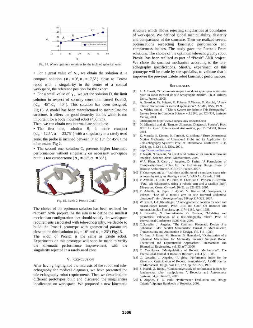
Fig. 14. Whole optimum solutions for the inclined spherical wrist
• For a great value of 3γ , we obtain the solution A: a
compact solution ( °=α°=α 5,17,0 10 ) close to Teresa
robot with a singularity in the center of a conical workspace, the reference position for the expert. • For a small value of 3γ , we get the solution D, the limit
solution in respect of security constraint named Estele2, ( °=α°=α 40,45 10 ). This solution has been designed,
Fig.15. A model has been manufactured to manipulate the structure. It offers the good dexterity but its width is too important for a body mounted robot (460mm). Then, we can obtain two intermediate solutions: • The first one, solution B, is more compact ( °=α°=α 75,23,5,12 10 ) with a singularity in a rarely used
zone, the probe is inclined between 0° to 10° for 45% time of an exam, Fig 2. • The second one, solution C, presents higher kinematic performances without singularity on necessary workspace but it is too cumbersome ( °=α°=α 35,35 10 ).
Fig. 15. Estele 2, Prosit1 CAD.
The choice of the optimum solution has been realized for “Prosit” ANR project. As the aim is to define the smallest mechanism configuration that should satisfy the workspace requirements associated with tele-echography, we decide to build the Prosit1 prototype with geometrical parameters close to the third solution (α0 = 10° and α1 = 23°) Fig.15. The width of Prosit1 is the same as Estele robot. Experiments on this prototype will soon be made to verify the kinematic performance improvement, with the singularity rejected in a rarely used zone.
V. CONCLUSION
After having highlighted the interests of the robotized tele-echography for medical diagnosis, we have presented the tele-echography robot requirements. Then we described the different prototypes built and discussed the singularities localization on workspace. We proposed a new kinematic
structure which allows rejecting singularities at boundaries of workspace. We defined global manipulability, dexterity and compactness of the structure. Then we realized several optimizations respecting kinematic performance and compactness indices. The study gave the Pareto’s Front solutions. The choice of the optimum tele-echography robot Prosit1 has been realized as part of “Prosit” ANR project. We chose the smallest mechanism according to the tele-echography specifications. Shortly, experiment on this prototype will be made by the specialist, to validate that it improves the previous Estele robot kinematic performances.
REFERENCES [1] L. Al Bassit, “Structure mécanique à modules sphériques optimisées
pour un robot médical de télé-échographie mobile”, Ph.D. Orleans Univ., France , 2005.
[2] A. Gourdon, Ph. Poignet, G. Poisson, P.Vieyres, P.,Marché, “A new robotic mechanism for medical application “, ASME, USA, 1999.
[3] A. Vilchis and al , “TER: A System for Robotic Tele-Echography”, Lecture Notes in Computer Science, vol.2208, pp. 326-334, Springer Verlag, 2001.
[4] Otelo project http://www.bourges.univ-orleans/Otelo [5] M. Mitsuishi and al, “Remote Ultrasound Diagnostic System”, Proc.
IEEE Int. Conf. Robotics and Automation, pp. 1567-1574, Korea, 2001.
[6] K. Masuda, E. Kimura, N. Tateishi, K. Ishihara, “Three Dimensional Motion Mechanism of Ultrasound Probe and its Application for Tele-echography System”, Proc. of International Conference IROS 2001, pp. 1112-1116, USA, 2001.
[7] http://www.medirob.com [8] F. Najafi, N. Sepehri, “A novel hand controller for remote ultrasound
imaging”, Science Direct- Mechatronics, 2008. [9] W.A. Khan, S. Caro , J. Angeles, D. Pasini, “A Formulation of
Complexity-Based Rules for the Preliminary Design Stage of Robotic Architectures”, ICED’07, France, 2007.
[10] F. Courreges and al, “Real-time exhibition of a simulated space tele-echography using an ultra-light robot”, ISAIRAS, Canada, 2001.
[11] P. Arbeille , J. Ruiz , P. Herve, M. Chevillot, G. Poisson, F. Perrotin, “Fetal tele-echography, using a robotic arm and a satellite link”. Ultrasound Obstet Gynecol; 26 (3): pp 221-226. 2005.
[12] P. Arbeille, A. Capri, J. Ayoub, V. Kieffer, M. Georgescu, G. Poisson, “Use of a robotic arm to tele operated abdominal ultrasound”. Am J Roentgenology; 188:pp 317-322. 2007.
[13] W. Khalil, J.-F.,Kleinfinger, “A new geometric notation for open and closed-looped robots”, Proc. IEEE Int. Conf. On Robotics and Automation, San Francisco, pp. 1174-1180, April 1986.
[14] L. Nouaille, N. Smith-Guerin, G. Poisson, “Modeling and geometrical validation of a tele-echography robot”, Proc. of International Conference IROS Nice, 2008.
[15] C.Gosselin, J. Angeles, “The Optimum Kinematic Design of a Spherical 3 dof parallel Manipulator Journal of Mechanisms”, Transmissions and Automation in Design, Vol. 111, 1989.
[16] M. Lum, J. Rosen, M. Sinanan, B. Hannaford, “Optimization of a Spherical Mechanism for Minimally Invasive Surgical Robot: Theoretical and Experimental Approaches”, Transactions and Biomedical Engineering, vol. 53, n°7, 2006.
[17] T. Yoshikawa, “Manipulability of Robotic Mechanisms”, The International Journal of Robotics Research, vol. 4 (2), 1985.
[18] C. Gosselin, J. Angeles, “A global Performance Index for the Kinematic Optimization of Robotic manipulators”, ASME Journal of Mechanical Design, Vol.113, n° 3, pp. 220-226, 1991.
[19] S. Kucuk, Z. Bingul, “Comparative study of performance indices for fundamental robot manipulators ”, Robotics and Autonomous Systems. 54, p. 567-573, 2006.
[20] J. Angeles, F. C. Park, “Performance Evaluation and Design Criteria”, Spinger Handbook of Robotics, 2008.
0
10
20
30
40
50
-10 0 10 20 30 40 50
alpha0
alp
ha1
optimum solutions
A B
C D
0α
1α
3506