design and control of a spherical omnidirectional...
TRANSCRIPT

Design and Control of a Spherical Omnidirectional Blimp
M. Burri, L. Gasser, M. Kach, M. Krebs, S. Laube, A. Ledergerber, D. Meier, R. Michaud, L. Mosimann,
L. Muri, C. Ruch, A. Schaffner, N. Vuilliomenet, J. Weichart, K. Rudin, S. Leutenegger,
J. Alonso-Mora, R. Siegwart, P. Beardsley
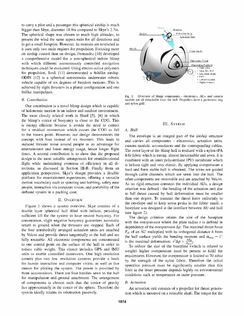
Abstract— This paper presents Skye, a novel blimp design.Skye is a helium-filled sphere of diameter 2.7m with a stronginelastic outer hull and an impermeable elastic inner hull. Fourtetrahedrally-arranged actuation units (AU) are mounted on thehull for locomotion, with each AU having a thruster which canbe rotated around a radial axis through the sphere center. Thisdesign provides redundant control in the six degrees of freedomof motion, and Skye is able to move omnidirectionally and torotate around any axis. A multi-camera module is also mountedon the hull for capture of aerial imagery or live video streamaccording to an ’eyeball’ concept - the camera module is notitself actuated, but the whole blimp is rotated in order to obtaina desired camera view.
Skye is safe for use near people - the double hull minimizesthe likelihood of rupture on an unwanted collision; the pro-pellers are covered by grills to prevent accidental contact; andthe blimp is near neutral buoyancy so that it makes only a lightimpact on contact and can be readily nudged away.
The system is portable and deployable by a single operator- the electronics, AUs, and camera unit are mounted externallyand are detachable from the hull during transport; operatorcontrol is via an intuitive touchpad interface.
The motivating application is in entertainment robotics.Skye has a varied motion vocabulary such as swooping andbobbing, plus internal LEDs for visual effect. Computer visionenables interaction with an audience. Experimental results showdexterous maneuvers in indoor and outdoor environments, andnon-dangerous impacts between the blimp and humans.
I. INTRODUCTION
This paper describes the design of Skye blimp, presents
experiments to demonstrate its capabilities under manual
control, describes the potential for flying autonomously, and
shows its suitability for safe deployment near people.
The design is symmetrical with a spherical hull, four
tetrahedrally arranged thrusters, and the center of gravity
(COG) close to the center of the sphere. There is no preferred
orientation or forward direction. The blimp is capable of
holonomic motion, able to translate in any direction and to
rotate around any axis independently. The design supports
flexible capture of aerial imagery according to an eyeball
concept - the camera module is fixed on the hull, and the
blimp is positioned and oriented as desired to obtain a
required camera view.
There is growing interest in low-cost unmanned aerial
vehicles (UAV) such as quadrotors and hexacopters across
M. Burri, L. Gasser, M. Kach, M. Krebs, S. Laube, A. Ledergerber,D. Meier, R. Michaud, L. Mosimann, L. Muri, C. Ruch, A. Schaffner,N. Vuilliomenet, J. Weichart, K. Rudin, J. Alonso-Mora, S. Leutenegger,R.Siegwart are with the Autonomous Systems Lab, ETH Zurich, 8092Zurich, Switzerland [email protected]
J. Alonso-Mora, P. Beardsley are with Disney Research Zurich, 8092Zurich, Switzerland {jalonso,pab}@disneyresearch.com
multiple domains - professional, hobbyist, and as toys. This
is bringing multicopters into closer proximity with people
and motivating a need for new safety concepts. Multicopter
safety can be achieved by low weight, propeller guards,
propeller auto-stop on obstruction, and autonomy if a manual
RC signal is lost. Low weight is achievable with quadrotors
as consumer product, but applications which require hard-
ware such as cameras, on-board storage, a wireless module,
and an on-board processor, can easily result in a payload of
500g and more. This is sufficient to cause injury if there is a
loss of control that causes the multicopter to fly into or fall
on a person. The problem is circumvented by a helium blimp
with neutral buoyancy. The worst-case failure scenario for a
blimp would be rupture of the hull, but this can be minimized
by a double hull like the design here. Skye’s propellers have a
protection ring and a nylon grill to prevent accidental contact.
The application is entertainment robotics. Some existing
examples of entertainment blimps have unusual shapes such
as jellyfish [1] or sharks [2]. Skye is a sphere and one goal
is to achieve entertaining effects using versatile motion and
eye-catching hull pattern. Internal LEDs enable nighttime
aesthetic effects, related to fireworks. Multiple blimps can
be choreographed in a collision-free aerial display using the
method described in [4]. A further goal is interaction, for
example to automatically detect gestures of individuals or
crowds using the onboard camera, to enable aerial games.
A. Related Work
Sharf [5], [6] presented a spherical indoor blimp to emu-
late a free floating object in a gravity-free environment. Like
Skye, it is able to perform six degrees of freedom motions but
achieves this by using six instead of Skye’s four propellers.
It is smaller than Skye with a diameter of 1.8m, but bound to
indoor use and limited payload. Minizepp [7] developed a se-
ries of indoor and outdoor blimps capable of aerial imagery,
which inspired Skye’s double hull. In recent years bigger
airships, suitable for intelligence gathering and information
transferring, experienced a renaissance. Unlike Skye these
airships are not meant to fly closely to objects and people, but
rather to operate in high altitude. Therefore more emphasis is
put on payload than on size and agility. An example of such
an airship is LEMV [8] (Long Endurance Multi-Intelligence
Vehicle) a recently developed hybrid airship for surveillance
operations which demonstrates the continued advantage of
airships for long deployment. Another project focusing on
long deployments and high altitudes is the SA-60 [9] devel-
oped by Techsphere Systems International. With the ability
2013 IEEE/RSJ International Conference onIntelligent Robots and Systems (IROS)November 3-7, 2013. Tokyo, Japan
978-1-4673-6357-0/13/$31.00 ©2013 IEEE 1873
1874

Fig. 2. A safety ring shields the propeller. It is stringed with threads toprevent fingers touching the blade. The lower part of the model shows theturning motor safely placed within the weight optimized aluminium frame.
Fig. 3. Plot of the effectiveness η in all spherical directions for the tetra-hedral actuation arrangement (left) and a planar placement as a reference(right).
rotation is provided by a maxon servomotor and transmitted
to the shaft by a gear mechanism. This construction enables
an unlimited number of revolutions. The electric current and
the signals for the thrust motor and controller are transmitted
over a slip ring which has to be in axes with the shaft. After
system start, all actuation units automatically go to a defined
position using a light barrier sensor.
The goal was to find the most suitable arrangement of
these AUs for omnidirectional flight properties maintaining
high efficiency in all directions. To compare them two
characteristic values were considered. For sake of simplicity,
only geometric constraints are considered, i.e. a perfect force
model is assumed. The translational effectiveness η is the
absolute value of the resulting force divided by the sum of
the absolute values of the thruster forces.
η =|Fres|
∑Ni|Fi|
(1)
A plot of η in all directions for a tetrahedral arrangement of
the AUs is shown if figure 3. As a reference, the plot for a
planar arrangement of four AUs is depicted too.
σ ∈ [1,N] is a way of measuring how much of the resulting
thrust must be contributed by one single motor:
σ =|Fres|
maxi (|Fi|)(2)
A σ of 1 indicates that the whole thrust is generated by one
motor where a σ of N denotes that all motors contribute
equally with |Fi|/|Fres|= 1/N each (e.g. |Fi|= 0.25|Fres| for
N = 4).
The tetrahedral solution was found to be the most suitable
to fulfill the requirements of omnidirectional motion. Addi-
tionally it has also the best worst directions of the considered
arrangements.
�������
����� ����������
�������������
������������
����������������
����������
���������
Fig. 4. Schematic illustration of the central electronics platform includingcontrol, camera and storage devices.
C. Electronics and Camera Module
All electronic components are attached on the surface
of the hull. The AUs are controlled by the central flight
management unit (FMU) from pixhawk [15] located at
the electronics platform (see figure 4). It incorporates a
3D accelerometer, gyroscope, magnetometer and a pressure
sensor as well as a local 168MHz processing unit where the
control loop is running. Furthermore, a u-blox GPS-receiver
is connected.
To address the AUs a communication system on the blimp
is required. It is implemented as a customized differential
RS485 bus system. This tailored solution allows a slim
realization of the cables and its differential format ensures
reliable data transmission over the large distances between
the nodes.
A LED chain is clutched straight through the inside of the
hull. A wire leads out through the hull outlet and is connected
to an AU. The chain is powered via a DC-to-DC converter
placed on an AU’s electronics board. An I2C bus is used
to control the LED color, which can be chosen by the pilot
on a color panel on the GUI. It is transmitted via the same
channels as motion control inputs.
Skye carries two low resolution cameras (MV BlueFox
MLC200wC) with a baseline of approximately 15cm and a
high resolution camera (AVT Prosilica GB2450C) located
near the BlueFox as it can be seen in figure 4. All pictures
captured are processed on a high level board (Pico ITX board
with Intel Atom processor 510D 1.66GHz) and stored on an
on-board solid state disk (SSD) while a WiFi module enables
a live stream to enhance piloting.
D. System Dynamics
Due to the six DOF of Skye in 3D space and numerous
unpredictable disturbances, a direct control of the system is
not sufficiently intuitive. Therefore, a control algorithm (see
section III-E) has been designed to make piloting feasible.
For a better understanding of the system dynamics and
to be able to develop a controller prior to the completed
construction of the prototype, a model was implemented in
MATLAB SIMULINK as shown in figure 5.
The system dynamics were modeled assuming rigid bod-
ies. To describe the system state, both a body frame (denoted
by B(.)) and an inertial frame (denoted by I(.)) are used as
they are visualized in figure 6.
1875

���������
��
�������
���������
����������
����
�����
�������
�����
������
�������
�����
����
�����
�������
���������� ����
���������� �������� ������� ���� �����
���� ������
Fig. 5. Closed loop control system in MATLAB SIMULINK
����
����
����
�
�
�
��
�
�
�
�
��
�
������
������ ������
�������������
������������
��������!�
��������
�
Fig. 6. Visualization of the used coordinate systems and the states (red).
To describe the state of the system the four vectorial equa-
tions (3-6) are used. Gravity and aerodynamical effects were
also included but are not discussed further. The translational
velocities result from the principle of linear momentum:
d
dtB~vCG = m−1
tot· B~Ftot,CG − B~ωIB × B~vCG , (3)
where B~Ftot is the resulting force (the sum of the forces
generated by the rotors, gravitational forces and forces gener-
ated by aerodynamic effects), mtot
the mass matrix including
aerodynamical effects and B~vCG the velocity of the center of
gravity.
The position can be calculated by integrating the velocity
vector in the inertial system:
d
dtI~xO−CG = I~vCG (4)
The angular velocities are evaluated with the principle of
angular momentum:
d
dtB~ωIB = BJ−1 ·
(
B~Mtot,CG − B~ωIB ×
(
BJ · B~ωIB
))
(5)
where B~ωIB is the angular velocity, BJ the inertia tensor
and B~Mtot,CG the resulting moment in the center of gravity.
The orientation is given by the unit quaternion ~qIB which
describes the rotation of the body relative to the inertial
frame. Its change is defined by the angular velocity ~ωIB:
d
dt~qIB =
1
2~qIB ⊗
(
0
B~ωIB
)
(6)
.
E. Control Algorithm
The control algorithm has been split into two parts to
allow a more intuitive design of the code (see figure 5). The
first part of the controller determines the required force and
moment. The state feedback is a quaternion calculated by
an Extended Kalman Filter (EKF) proposed by Leutenegger
[14]. The second stage is the conversion of force and moment
into thrust and position of the AUs, referred to as allocation.
The control strategy follows a hierarchical structure, be-
ginning with the state feedback linearization of the velocity
and angular velocity equations to decouple translations from
rotations by eliminating the cross product terms. While the
attitude equation is linearized by the Jacobian, the position
equation is simply used in the inertial frame, where it appears
in its linear form. The resulting control problem is then
solved by the implementation of two sets of cascaded control
loops consisting of an inner P and outer PI regulator for
position and velocity, as well as attitude and angular velocity.
A differential part is not implemented since the inner loop
implicitly acts as a derivative part for the outer loop in
cascaded loop strategies (see figure 7).
ì(dq/dt)dt CAttitude
CAngvel
Plant
&des q
des &res
&meas
qmeas
Fig. 7. Cascaded control structure with angular velocity controller andattitude hold block.
With this method the controller determines the optimal
force and momentum to act on the COG of the system. As
the actuation performance is limited, anti integral windup
and restriction loops were implemented such that the con-
troller does not request actuation values beyond the systems
capabilities.
The allocation calculates the signals for the positioning
and thrust motors. As the system has eight inputs (thrust Fi
and direction αi for each AU), two degrees of freedom can
be used for an optimization of the signals for the motors. In
order to simplify the allocation of the actuators the following
assumptions were made:
• Negligible thrust motor dynamics: It is supposed that the
thrust motor can reach every rotational speed within a
certain range immediately.
• Linearized positioning motor dynamics: Neglecting ac-
celeration (and deceleration) the required time to sweep
a certain angle is linear to the angle offset.
• Negligible drag torque: The drag torque of the propeller
is about a hundred times smaller than the torque result-
ing from the thrust force.
• Linear thrust approximation: A linear function was fitted
experimental results to relate the thrust motor signal to
the thrust force.
1876
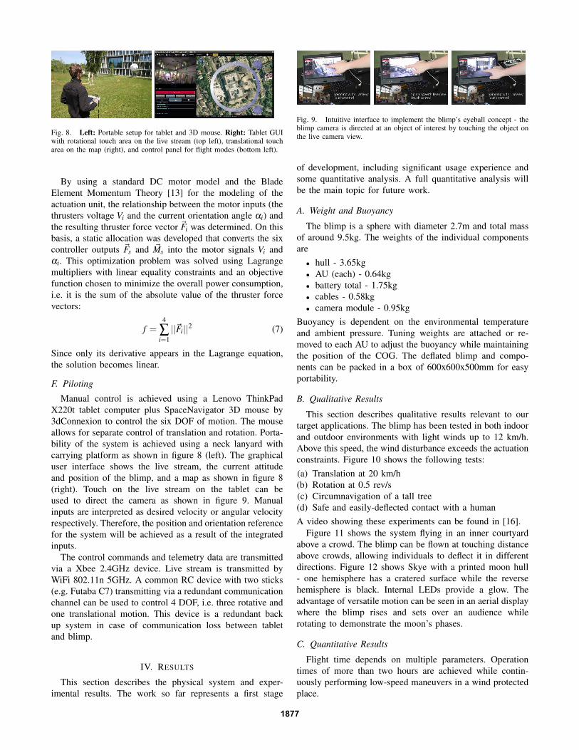
Fig. 8. Left: Portable setup for tablet and 3D mouse. Right: Tablet GUIwith rotational touch area on the live stream (top left), translational toucharea on the map (right), and control panel for flight modes (bottom left).
By using a standard DC motor model and the Blade
Element Momentum Theory [13] for the modeling of the
actuation unit, the relationship between the motor inputs (the
thrusters voltage Vi and the current orientation angle αi) and
the resulting thruster force vector ~Fi was determined. On this
basis, a static allocation was developed that converts the six
controller outputs ~Fs and ~Ms into the motor signals Vi and
αi. This optimization problem was solved using Lagrange
multipliers with linear equality constraints and an objective
function chosen to minimize the overall power consumption,
i.e. it is the sum of the absolute value of the thruster force
vectors:
f =4
∑i=1
||~Fi||2 (7)
Since only its derivative appears in the Lagrange equation,
the solution becomes linear.
F. Piloting
Manual control is achieved using a Lenovo ThinkPad
X220t tablet computer plus SpaceNavigator 3D mouse by
3dConnexion to control the six DOF of motion. The mouse
allows for separate control of translation and rotation. Porta-
bility of the system is achieved using a neck lanyard with
carrying platform as shown in figure 8 (left). The graphical
user interface shows the live stream, the current attitude
and position of the blimp, and a map as shown in figure 8
(right). Touch on the live stream on the tablet can be
used to direct the camera as shown in figure 9. Manual
inputs are interpreted as desired velocity or angular velocity
respectively. Therefore, the position and orientation reference
for the system will be achieved as a result of the integrated
inputs.
The control commands and telemetry data are transmitted
via a Xbee 2.4GHz device. Live stream is transmitted by
WiFi 802.11n 5GHz. A common RC device with two sticks
(e.g. Futaba C7) transmitting via a redundant communication
channel can be used to control 4 DOF, i.e. three rotative and
one translational motion. This device is a redundant back
up system in case of communication loss between tablet
and blimp.
IV. RESULTS
This section describes the physical system and exper-
imental results. The work so far represents a first stage
Fig. 9. Intuitive interface to implement the blimp’s eyeball concept - theblimp camera is directed at an object of interest by touching the object onthe live camera view.
of development, including significant usage experience and
some quantitative analysis. A full quantitative analysis will
be the main topic for future work.
A. Weight and Buoyancy
The blimp is a sphere with diameter 2.7m and total mass
of around 9.5kg. The weights of the individual components
are
• hull - 3.65kg
• AU (each) - 0.64kg
• battery total - 1.75kg
• cables - 0.58kg
• camera module - 0.95kg
Buoyancy is dependent on the environmental temperature
and ambient pressure. Tuning weights are attached or re-
moved to each AU to adjust the buoyancy while maintaining
the position of the COG. The deflated blimp and compo-
nents can be packed in a box of 600x600x500mm for easy
portability.
B. Qualitative Results
This section describes qualitative results relevant to our
target applications. The blimp has been tested in both indoor
and outdoor environments with light winds up to 12 km/h.
Above this speed, the wind disturbance exceeds the actuation
constraints. Figure 10 shows the following tests:
(a) Translation at 20 km/h
(b) Rotation at 0.5 rev/s
(c) Circumnavigation of a tall tree
(d) Safe and easily-deflected contact with a human
A video showing these experiments can be found in [16].
Figure 11 shows the system flying in an inner courtyard
above a crowd. The blimp can be flown at touching distance
above crowds, allowing individuals to deflect it in different
directions. Figure 12 shows Skye with a printed moon hull
- one hemisphere has a cratered surface while the reverse
hemisphere is black. Internal LEDs provide a glow. The
advantage of versatile motion can be seen in an aerial display
where the blimp rises and sets over an audience while
rotating to demonstrate the moon’s phases.
C. Quantitative Results
Flight time depends on multiple parameters. Operation
times of more than two hours are achieved while contin-
uously performing low-speed maneuvers in a wind protected
place.
1877

Fig. 10. Qualitative results obtained for outdoor deployment. (a) Transla-tion at 20km/h. (b) Rotation at 0.5 rev/s. (c) Circumnavigating a tree. (d)
Safe and easily-deflected contact with a human.
Fig. 11. Safe operation over crowds.
Fig. 12. Skye as the moon. A printed hull and internal LEDs enablenighttime aesthetic effects.
Quantitative results are provided for the adherence of the
blimp to a specified rotational motion. The input angular
velocity is compared with the angular velocity estimated by
the sensor system. Figure 13 shows results achieved by a
cascaded attitude controller by applying a sinusoidal angular
velocity input in the z-direction. The controller was imple-
mented according to the method described in Section III-
E. Controller gains were found by respecting the crossover
frequency ωc, which is, as a rule of thumb, set two octaves
below the characteristic frequency ωchar. The characteristic
frequency is given by the time Tchar = 0.31s used to orient
the thrusters into the opposite direction. Therefore
ωc =ωchar
4=
π
4 ·Tchar
(8)
which was found to be 2.5rad/s. Accordingly, the controller
gains used were kp,ω = 2.5 for the inner P controller, and
kp,φ = 0.25,TI,φ = 4s for the outer PI control loop.
0 5 10 15 20 252
1
0
1
2
t [s]
An
g.
Vel
.[r
ad/s
]
Fig. 13. System response of all angular directions x,y,z to a sinusoidalangular velocity input in only one angular direction z. ωz input [blue], ωx
[red dashed], ωy [green dashed], ωz [cyan dashed].
D. Interaction using Computer Vision
An example interaction with an audience on the ground is
to detect areas of large motion in the camera image, and then
respond, for example, by approaching and circling that place.
Figure 14 shows the detected motion for an individual who is
jumping. The vision system utilizes a standard approach. The
processing steps, which can be found individually in [17], are
• Determine the epipolar geometry of successive frames
in an image sequence by feature detection and corre-
spondence matching, using a method that is robust to
the presence of independent motion
• Detect features with independent motion by testing
for matched features that disagree with the epipolar
geometry
• Group features with independent motion into blobs
using mathematical morphology
• Take the largest blob as the target for the subsequent
interaction
V. CONCLUSION AND FUTURE WORK
This paper has presented Skye, a spherical helium blimp
capable of holonomic motion that is suitable for enter-
tainment applications close to people. The paper presented
qualitative results plus initial quantitative analysis. A full
quantitative analysis is the topic of the next stage of work.
1878

Fig. 14. Computer vision algorithm to detect a waving user. From left,one frame of a captured sequence, detected motion, detected rectangle oflargest motion.
The work can be considered in the context of recent
interest in using quadrotors to make flying displays. Quadro-
tors are capable of fast and versatile motion, but there are
currently safety challenges in placing them overhead or
close to people, requiring further research to resolve. In
contrast, Skye has been safely deployed within touching
distance of crowds of people - the blimp is near neutral
buoyancy and can be readily pushed away, and the propellers
are protected by a nylon grill. As a further advantage for
human settings including entertainment, the blimp has quiet
operation - lifting force is delivered by the helium and
thrust is selectively activated only as needed for a desired
motion or to counteract wind disturbances. This also has
the consequence that Skye has a longer operation time than
conventional quadrotor systems.
Illuminated with internal LEDs, the blimp provides an at-
tractive nighttime display in the same spirit as fireworks. The
onboard camera and processor supports interactive games
based on individual gesture or crowd motion. In conclusion,
Skye is intended to be a flexible platform for aerial display
and for interactive games.
REFERENCES
[1] Festo AirJelly, festo.com/cms/en corp/9771.htm
[2] AirSwimmers, airswimmersworld.com
[3] O. Bimber, D. Iwai, G. Wetzstein, A. Grundhoefer, The VisualComputing of Projector-Camera Systems, Computer Graphics Forum,2008.
[4] J. Alonso-Mora, M. Schoch, A. Breitenmoser, R.Y. Siegwart, P. Beard-sley, Object and Animation Display with Multiple Aerial Vehicles:Proc. of the IEEE/RSJ International Conference on Intelligent Robotsand Systems (IROS), 2012
[5] I. Sharf, B. Laumonier, M. Persson, J. Robert, Control of a fully-actuated airship for satellite emulation: International Conference onRobotics and Automation (ICRA), May 2008
[6] S. Mikael Persson, I. Sharf, Dynamics, Stability and Control of IndoorSpherical Airship: 7th European Nonlinear Dynamics Conference, July2011
[7] Minizepp, minizepp.com
[8] U.S. Army LEMV, http://www.northropgrumman.com/Capabilities/lemv
[9] SA-60, http://defensetech.org/2004/07/06/blimpball-in-navy-tests/
[10] J.P. Fernandez, P. Gonzalez, R. Sanz, W. Burgard, Developing a Low-Cost Autonomous Indoor Blimp: Journal of Physical Agents, vol 3 no1, 2009.
[11] C. Jordi, S. Michel, N. Widmer, V. Frohne: Body segment of an activeairship based on dielectric elastomers: 19th International Conferenceon Adaptive Structures and Technologies, Ascona, Switzerland, 2008.
[12] S. K. Choi, J. Yuh: Design of Advanced Underwater Robotic Vehicleand Graphic Workstation: Autonomous Systems Laboratory, Univer-sity of Hawaii, IEEE 1993
[13] A.R.S Bramwell, G. Done, D. Balmford, Helicopter Dynamics:Butterworth-Heinemann, 2nd edition, 2001.
[14] S. Leutenegger, R.Y. Siegwart, A Low-Cost and Fail-Safe Inertial Nav-igation System for Airplanes: International Conference on Roboticsand Automation (ICRA), 2012
[15] Pixhawk, pixhawk.ethz.ch
[16] Project Skye, www.skye.ethz.ch
[17] R. Hartley, A. Zisserman, Multiple View Geometry in ComputerVision, Cambridge University Press, 2004.
1879