a flying robot with adaptive morphology for multi-modal...
TRANSCRIPT

A Flying Robot with Adaptive Morphology for Multi-Modal Locomotion
Ludovic Daler, Julien Lecoeur, Patrizia Bernadette Hahlen and Dario Floreano
Abstract— Most existing robots are designed to exploit onlyone single locomotion mode, such as rolling, walking, flying,swimming, or jumping, which limits their flexibility and adapt-ability to different environments where specific and differentlocomotion capabilities could be more effective. Here we in-troduce the concept and the design of a flying robot withAdaptive Morphology for Multi-Modal Locomotion. We presenta prototype that can use its wings to walk on the ground andfly forward. The wings are used as whegs to move on roughterrains. This solution allows to minimize the structural massof the robot by reusing the same structure (here the wings) fordifferent modes of locomotion. Furthermore, the morphologyof the robot is analysed and optimized for ground speed.
I. INTRODUCTION
There is a growing interest in the use of robots for applica-tions such as exploration, search-and-rescue, or monitoringof the environment [1]. These robots have to deal with verycomplex terrains, such as semi-collapsed buildings, deepcaverns, or forests with a lot of vegetation. Autonomousrobots are appealing for these tasks due to their ability toexplore areas that are risky and inaccessible to humans [2].
However, existing platforms have limited locomotion abil-ities. Most existing mobile robots exploit only one singlelocomotion strategy, such as rolling, walking, flying, hover-ing, climbing, swimming, crawling, or jumping. Operatingin complex terrains is very challenging for mobile robotssince the topology of the terrain could be subject to sig-nificant variations. Therefore, using only one locomotionstrategy limits their flexibility and adaptability to differentenvironments. For example, obstacles larger than the sizeof a robot represent a significant challenge for groundlocomotion, but flying robots can easily overcome theseobstacles. In a search-and-rescue scenario there is a need tofly quickly over extended areas, thereby the use of a wingedrobot is interesting. However, careful exploration in confinedenvironments or near the ground is challenging for flyingrobots.
Terrestrial locomotion is more energy efficient over shortdistances; flying forward requires gaining speed, and hov-ering flight with a prop-hanging system consumes a lot ofenergy [3] and flapping even more [4]. For instance one cannotice that birds and insects use their legs to move aroundover short distances and rest on the ground, but prefer tofly over long distances. For these reasons, a robot capableof ground locomotion and of flying-hovering locomotion iswell suited to navigate in complex environments.
L. Daler, J. Lecoeur and D. Floreano are with the Laboratory of IntelligentSystems (http://lis.epfl.ch) at Ecole Polytechnique Federale de Lausanne(EPFL), CH1015 Lausanne, Switzerland (email: [email protected]).
Fig. 1: 1st prototype of the Deployable Air Land ExplorationRobot (DALER) a flying and walking robot that uses itswings as whegs to move on the ground.
At first sight, multi-modal locomotion seems to be a goodapproach for improving the mobility of flying robots. How-ever, the implementation of this solution into mobile robotsshowed that the addition of a second mode of locomotion onthe platform could lead to a significant loss of performance ofthe two modes of locomotion if the two modes of locomotiondo not share part of their structure or actuators [5], [6],[7], [8]. This effect is mainly caused by the weight addedto the platform and the increased complexity of the robot.Therefore, it reduces the operating capabilities of each modeof locomotion and thus the overall mobility of the robot. Forflying robots this disadvantage is even more significant, sinceincreasing the weight could lead to the inability to take off.
Therefore, we propose a new approach, which we call”Adaptive Morphology1”, where parts of the structure of arobot are shared between the different modes of locomotion,instead of simply adding a second locomotion structure to anexisting robot. Moreover, the structure could self-adjust theshape to adapt to the locomotion mode. The efficiency oflocomotion in each mode of locomotion can be improvedthrough adaptive morphology suitable for that mode. Anexample of an animal that uses adaptive morphology toimprove its mobility is the salamander, which is capable ofwalking and rolling. Its body, originally shaped for walking,can take the shape of a large wheel to roll downhill [9].Birds and other flying animals such as bats, use their wingsfor many different tasks, such as flying forward, stalling,hovering, squeezing through small openings, rolling over,walking, righting, and perching [10].
1In biology, morphology deals with the study of the form and structureof organisms and their specific structural features, such as aspects of theexternal appearance (shape, structure, pattern) and the form and structureof the internal parts.
2013 IEEE/RSJ International Conference onIntelligent Robots and Systems (IROS)November 3-7, 2013. Tokyo, Japan
978-1-4673-6357-0/13/$31.00 ©2013 IEEE 1361

We aim to make adaptive deployable wings for improvingthe mobility of a flying robot, because having adaptive wingswould provide many advantages. The wings are the largestcomponents of the robot and their shape could be adaptivelymodified to augment efficiency of forward flight, hover flight,and displacement on the ground. For example, wings couldbe fully deployed for flying outdoors and reduced for hoverflight and ground modes. Moreover, the wings structure couldtake the shape of whegs [11] in ground locomotion mode.Figure 2 shows a schematic representation of a flying robotcapable of air and ground multi-modal locomotion (we calledthis robot DALER for Deployable Air Land ExplorationRobot), and Fig. 1 shows the first prototype of this concept.
The design process that lead to this robot is presentedin section III, along with two different prototypes thatcan use their wings to move on the ground using twodifferent approaches. Then, the selected ground locomotionconfiguration is analysed and the morphology of the robot ismodelled in a physics based simulator to optimize groundlocomotion speed. Finally, the mechanical design of theDALER prototype that was built is presented in sectionIV. This prototype validates the concept of walking on theground by using the wings as whegs. Finally, the flightcapabilities of the two prototypes are analysed; in forwardflight for the DALER and in hover flight for the other one.
Fig. 2: Representation of the DALER flying robot thatuses Adaptive Morphology for Multi-Modal Locomotion toperform a search-and-rescue mission. (A) Forward flight, (B)transition to hover flight, (C) reduce the wings’ span, (D)enter a building trough a small opening, (E) hover indoors,(F) land on the ground, (G-H) move on the ground, (I)transition to hover flight, (J) take-off, (K) exit the building,and (L) transition back to forward flight.
II. RELATED WORK
Recently, some robots have been developed to displaymultiple modes of locomotion (e.g. hover-roll/walk, or flight-roll/walk). Most of them are however optimized for onemode of locomotion and the second is often neglected. Noneof them reuse the same structure for different modes oflocomotion in order to minimize weight and improve theeffectiveness of each mode of locomotion.
BOLT [7] is a lightweight bipedal ornithopter capableof high-speed dynamic running and effecting transitions
between aerial and terrestrial locomotion modes. This robot,due to its small size, can only run over small obstacles. Asmall ground robot designed by Kossett et al. [5], whichhas the ability to fly, utilizes a minimalistic wheeled groundmode to minimize weight, and a rotary-wing flight mode,enabling transformations at will. This design is ideal forhovering in an indoor environment and rolling on a flatground, but it is not yet capable of rolling in rough terrainsor flying over long distances. MALV [8] is a biologicallyinspired Micro Air-Land Vehicle. It flies using a chord-wise, undercambered, bat-like compliant wing and walksover rough terrain using passively compliant whegs. MALVperforms transition from flight to walking but most of thetime cannot get back to the air, since it can only take off fromthe roof of a building of at least 6 meters high. The Japaneseministry of defense designed a spherical flying robot roughlythe shape and size of a soccer ball. It has the capacity to landon the ground and roll, however, the ground locomotion isvery limited since it can only roll passively on the groundto absorb the energy of the crash. MAVion Roll and Fly [12]is an aircraft with vertical take off and landing capability(VTOL), it has carbon fiber wheels to roll along grounds,walls and ceilings. Yet, the ground capabilities of this robotare limited since the wheels are only passive.
III. DESIGN OF THE PLATFORM
This section presents the selection and the design of theplatform configurations for the ground and air locomotionmodes. The selection of the type of configuration can bedone from two different approaches; either we can start froma ground based platform and enable it with flying capabilitiesor start from a flying robot and make it move on the ground.Thus, we decided to analyze a search-and-rescue missionscenario in order to study the requirements of the robot. Weexpect that most of the distance travelled during the missionwill be in the air. Consequently, we select first the type ofairframe for the forward flight and look at how we couldenable it with hovering and ground capabilities. Finally, themorphology of the robot is optimized with a simulator forthe ground locomotion mode.
A. Platform Requirements
The first step of the design of a robot capable of multi-modal ground and air locomotion is to define a list of missionspecification such as flight distance, hover duration, grounddistance, and payload capacity of the robot.
We based our analysis on a real life example such asthe recent earthquake that happened in Haiti, in January2010, which destroyed almost completely the city of Port-au-Prince. When autonomous robots could have been used tolocalize people stuck in collapsed houses all around the city.In this scenario, the platform must be able to reach any pointin the city starting from its center and come back. The radiusof the city is approximatively 5 km, giving a travel distanceof 10 km. The estimated time needed to enter and exit ahouse is around 5 minutes in total and the platform must haveenough energy in order to move on the ground to explore
1362
a small house. Apart from fulfilling these requirements therobot must also be capable of vertical take off and landingand of passing through small openings (to enter/leave thehouse). It must be robust against landings on any terrain,able to transition from ground mode to hover flight, and ableto transition from hover flight to forward flight. Furthermore,in order to be safe for the people around, the total mass mustbe minimized.
B. Platform Type Selection
Considering these mission requirements, systematic anal-ysis of the different airframe configurations, hovering meth-ods, and wing-aided ground locomotion solutions were per-formed. As mentioned before, the priority will be given to theforward flight mode of locomotion since we want to coverlong distances quickly.
Regarding the type of airframe; flapping-wing have beenexcluded from the beginning because of their mechanicalcomplexity. Lighter-than-air platforms have been left out aswell because of their low payload capacity per volume [13].Therefore, fixed-wing airframes remain as the most suitablechoice for forward flight and rotary-wings for hover flight.The design of a flying robot usually begins with decisionson the kind and size of the airframe to be used, we usedthe methodology presented in Leven’s thesis [14], wheremany possible configurations of fixed-wing airframes arepresented. The ”flying wing” configuration was selectedfor the forward flight configuration. This airframe’s maincharacteristic is the absence of a fuselage and tail, making itsimple to construct and robust to landings. The airframe isinherently stable and provides good manoeuvrability.
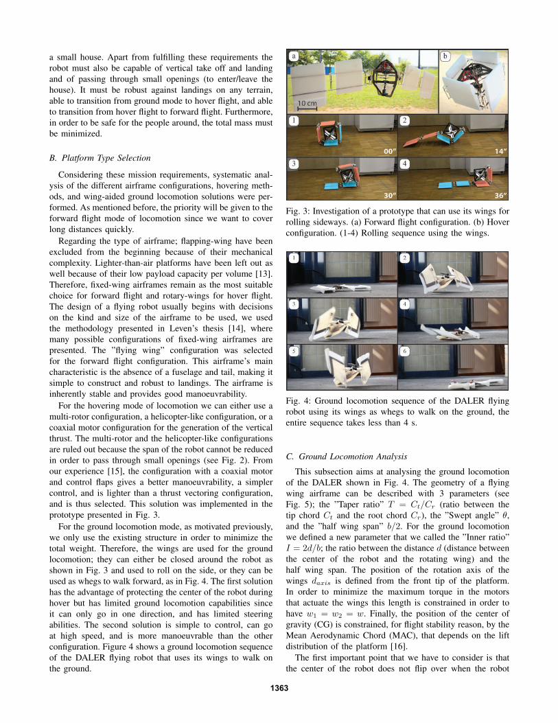
For the hovering mode of locomotion we can either use amulti-rotor configuration, a helicopter-like configuration, or acoaxial motor configuration for the generation of the verticalthrust. The multi-rotor and the helicopter-like configurationsare ruled out because the span of the robot cannot be reducedin order to pass through small openings (see Fig. 2). Fromour experience [15], the configuration with a coaxial motorand control flaps gives a better manoeuvrability, a simplercontrol, and is lighter than a thrust vectoring configuration,and is thus selected. This solution was implemented in theprototype presented in Fig. 3.
For the ground locomotion mode, as motivated previously,we only use the existing structure in order to minimize thetotal weight. Therefore, the wings are used for the groundlocomotion; they can either be closed around the robot asshown in Fig. 3 and used to roll on the side, or they can beused as whegs to walk forward, as in Fig. 4. The first solutionhas the advantage of protecting the center of the robot duringhover but has limited ground locomotion capabilities sinceit can only go in one direction, and has limited steeringabilities. The second solution is simple to control, can goat high speed, and is more manoeuvrable than the otherconfiguration. Figure 4 shows a ground locomotion sequenceof the DALER flying robot that uses its wings to walk onthe ground.
Fig. 3: Investigation of a prototype that can use its wings forrolling sideways. (a) Forward flight configuration. (b) Hoverconfiguration. (1-4) Rolling sequence using the wings.
Fig. 4: Ground locomotion sequence of the DALER flyingrobot using its wings as whegs to walk on the ground, theentire sequence takes less than 4 s.
C. Ground Locomotion Analysis
This subsection aims at analysing the ground locomotionof the DALER shown in Fig. 4. The geometry of a flyingwing airframe can be described with 3 parameters (seeFig. 5); the ”Taper ratio” T = Ct/Cr (ratio between thetip chord Ct and the root chord Cr), the ”Swept angle” θ,and the ”half wing span” b/2. For the ground locomotionwe defined a new parameter that we called the ”Inner ratio”I = 2d/b; the ratio between the distance d (distance betweenthe center of the robot and the rotating wing) and thehalf wing span. The position of the rotation axis of thewings daxis is defined from the front tip of the platform.In order to minimize the maximum torque in the motorsthat actuate the wings this length is constrained in order tohave w1 = w2 = w. Finally, the position of the center ofgravity (CG) is constrained, for flight stability reason, by theMean Aerodynamic Chord (MAC), that depends on the liftdistribution of the platform [16].
The first important point that we have to consider is thatthe center of the robot does not flip over when the robot
1363

Fig. 5: Model of robot with dimension parameters.
is climbing a slope. Figure 6.a shows a schema of the robotseen from the side on a slope of angle β. To prevent flipping,the following condition has to be maintained:
w < daxiscos(β). (1)
Otherwise the center part of the robot would rotate insteadof the wings, because the gravitational force would pullit backwards. Figure 6.b shows the corresponding limitsituation.
Fig. 6: (a) Schema of the robot seen from the side on a slopewith dimension parameters; the center part in dark grey andthe wing in light grey. (b) Limit of stability; for bigger valuesof β or w, the robot would fall backwards. (c) Free bodydiagram; center part on the left, and wings on the right.
The second important point to consider is that the wings donot slip on the ground, the dynamic friction force T = µNat point A should be smaller than at point B, so that contactpoint A slips on the ground but not contact point B (seeFig. 6):
µANA < µBNB . (2)
To evaluate this condition the model is separated into twobodies (see Fig. 6.c). We make the hypothesis that the massof the wings can be neglected compared to the total massof the robot. As there are two wings and two motors, thecontact forces at point B and C are doubled. Ideally, thecontact points of the wings (point B in Fig. 6) should notslip on the ground. From Newton’s and Euler’s equationsapplied on this system (at angle ϕ = 0o) we can deduce:
NA = mg
(1 − dCG
daxis + w
)(3)
NB = mgdCG
2(daxis + w)(4)
which lead to the following inequality:
daxis + w
dCG< 1 +
µB
2µA. (5)
The friction between the ground and the robot has aninfluence on the admitted limit values of the parameters. Thefriction coefficient at the contact point on the center part Ashould be reduced to a minimum to permit a slipping-lessrotation of the wings.
When the constraint (5) is satisfied, the transversal contactforce is determined by the friction at point A and can be usedto evaluate the torque required by the motors:
TA = 2TB = 2TC = µANA. (6)
Hence, the torque for one motor (at ϕ = 0o):
M =1
2mg
dCG
1 + daxis
w
. (7)
For higher values of ϕ, the required torque depends also onthe friction coefficient between the contact point of the robotA and the ground. For a good efficiency of the locomotion,the required torque should be as small as possible and thecovered distance per revolution should be as long as possible.The length of the covered distance l per rotation of the wingsis proportional to w, assuming that the wings do not slip:l = 4w. Supposing that the robot moves forwards with acertain mean speed v, the required average rotational speedof the wings Ω is:
Ω = v2π
l= v
π
2w. (8)
D. Morphology Optimization
The theoretical analysis presented above gives guidelinesfor the design of the geometry of the platform, howevermany different combinations of the different parameters(taper ratio, swept angle, and inner ratio) satisfy the aboveconditions. Therefore, in order to optimize the morphology ofthe robot, it was modelled in a physics based simulator, usingthe Open Dynamic Engine (ODE) library, and the differentparameters were optimized for maximizing the speed of therobot in the ground locomotion mode.
1364

Fig. 7: Distance travelled for one revolution of the wings, and sample set of morphologies. The swept angle is the angle θshown in Fig. 5, the Taper ratio is ratio between the tip chord and the root chord T = Ct/Cr, and the Inner ratio is the ratiobetween the distance d (distance between the center of the robot and the rotating wing) and the half wing span I = 2d/b.
Figure 7 shows the distance travelled for the differentconfigurations. Each point represents a different geometry ofthe robot and the color represents the travelled distance forone complete revolution of the wings. The x axis representsthe inner ratio (from 20 to 80%), the y axis the taperratio (from 30 to 100%), and the z axis the swept angle(from 5o to 45o). Points that are missing on the graph aregeometries where the axis of rotation of the wings wouldhave been outside of center part of the robot, and thus are notevaluated. This figure also shows the extreme configurationsof the robots. From the graph we can see that the bestresults are obtained for a medium swept angle (between 20o
and 30o), a large taper ratio ( 65%), and a small innerratio ( 50%). The point with the highest value has thefollowing parameters: inner ratio 35%, taper ratio 95%, andswept angle 26o. The prototype that we built to validate thisconcept was thus designed using these same parameters, andis presented in the next section. These parameters do nothave a significant impact on the forward flight performanceof the robot. However, the airfoil profile and the placementof the CG must be carefully adapted to the wing geometry.
IV. PROTOTYPING
This section presents the important aspects of the mechan-ical design of the DALER, its ground and forward flightlocomotion capabilities.
A. Mechanical Design
For the flight mode of locomotion the wings have to besufficiently rigid in order to sustain the lift force and forthe ground mode it must sustain high torsion forces duringwalking. The prototype was thus 3D printed in plastic, thewings structure was optimized for rigidity and weight. Thetotal weight of the robot is 450 g for a wing span of 60 cm.
The rotation of the wings must be locked during flight,thus a locking mechanism is used to freeze the rotation ofthe wings. Figure 8.C and D show this locking mechanism,
TABLE I: Friction coefficients.
Parquet Carpet Road Grass
Robot center µA 0.3 0.4 0.5 0.5Wings µB 0.45 1.8 1.7 1.61 + µB
2µA1.75 3.25 2.7 2.6
and Fig. 8.B shows the axis of rotation of the wing, the motorthat is hidden inside the center of the robot, the gears, andthe slip ring. The slip rings prevent the servo-motors’ cables,used for the flaps on the wings, to be twisted.
Finally, Fig. 8.A and D show the small hooks that wereadded on the wings to increase the friction with the ground,they are covered with a very rough tape. Table I givesthe friction coefficients on different surfaces for the wingsand for the center of the robot. The relation between theparameters daxis+w
dCGfor this robot is equal to 2.5. Therefore,
we can see that equation (5) is satisfied for all surfaces exceptfor the parquet that is very slippery. The robot can still walkon the parquet but is less efficient than on the other surfaces,since it is slipping only on a small portion of each step.
B. Ground and Air Locomotion Capabilities
The flight and walking abilities of the DALER prototypecan be seen in the accompanying video. This prototype iscapable to walk on different terrains, such as on parquet, oncarpet, in snow, on a road, and on grass (see Fig. 9). Whenthe wings rotate synchronously at cruise speed the robot cango at 0.2 m/s (or 0.66 BL/s) and can rotate on spot at 25o/s.
It can fly at about 14m/s, is robust to landings at thatspeed, and the autonomy of such flying wing is about 30minutes in forward flight. The hover flight with contra-rotating propellers and flaps in the airflow was implementedion the other prototype (see Fig. 3). This prototype can hoverfor about 10 minutes and is very stable and manoeuvrable.This solution will thus integrated in the next version of the
1365

Fig. 8: (A) and (D) small hooks added on the wings and covered with rough tape to increase the friction with the ground.(C) locking mechanism; the servo-motor arm is in position 1 (arm retracted) when the robot walks on the ground, then itcan be open to position 2 and the wings rotate until the arm of the servo-motor slices into the corresponding slot 2 (shownin D), and finally the wings are locked when the arm is in position 3. (B) Slip ring, motor, gears and axis of rotation.
DALER prototype. To transition between hover and forwardflight the robot can either accelerate vertically to gain speedand slowly pith down, or it can perform a dive to gain speedand then pitch up (we achieved this with a third prototype).
Fig. 9: Ground locomotion on different types of terrain. (A)On parquet, (B) on carpet, (C) in snow, (D) on a road, (E)going down a step, and (F) on grass.
V. CONCLUSION AND FUTURE WORKWe designed a platform that is capable of multi-modal air
and ground locomotion, and the use of the wings as whegsallows to keep the total mass of the platform low. Further-more, the platform is effective in both modes of locomotion.Hover flight was experimented in an other prototype andfuture work will be done on enabling the DALER platformwith hovering capabilities and adaptive deployable wings, inorder to achieve the scenario presented in the introduction.
ACKNOWLEDGMENTSThis work was supported by the Swiss National Science
Foundation through the National Centre of Competence inResearch Robotics.
REFERENCES
[1] T. Chung, G. Hollinger, and V. Isler, “Search and pursuit-evasion inmobile robotics: A survey,” Autonomous robots, vol. 31, no. 4, pp.299–316, 2011.
[2] S. Tadokoro, Rescue Robotics: DDT Project on Robots and Systemsfor Urban Search and Rescue. Springer Verlag, 2009.
[3] H. Tennekes and H. Tennekes, The simple science of flight: frominsects to jumbo jets. The MIT Press, 2009.
[4] D. Lentink and M. Dickinson, “Biofluiddynamic scaling of flapping,spinning and translating fins and wings,” Journal of ExperimentalBiology, vol. 212, no. 16, p. 2691, 2009.
[5] A. Kossett, R. D’Sa, J. Purvey, and N. Papanikolopoulos, “Design ofan improved land/air miniature robot,” in Robotics and Automation(ICRA), 2010 IEEE International Conference on. IEEE, 2010, pp.632–637.
[6] M. Kovac, J. Zufferey, and D. Floreano, “Towards a self-deployingand gliding robot,” Flying insects and robots, 2009.
[7] K. Peterson and R. Fearing, “Experimental dynamics of wing assistedrunning for a bipedal ornithopter,” in Intelligent Robots and Systems(IROS), 2011 IEEE/RSJ International Conference on. IEEE, 2011,pp. 5080–5086.
[8] R. Bachmann, F. Boria, R. Vaidyanathan, P. Ifju, and R. Quinn, “Abiologically inspired micro-vehicle capable of aerial and terrestriallocomotion,” Mechanism and Machine Theory, vol. 44, no. 3, pp. 513–526, 2009.
[9] M. Garcıa-Parıs and S. Deban, “A novel antipredator mechanism insalamanders: rolling escape in hydromantes platycephalus,” Journal ofherpetology, vol. 29, no. 1, pp. 149–151, 1995.
[10] G. Taylor, A. Carruthers, T. Hubel, and S. Walker, “Wing morphing ininsects, birds and bats: Mechanism and function,” Morphing Aerospacevehicles and structures, p. 13, 2012.
[11] R. Quinn, D. Kingsley, J. Offi, and R. Ritzmann, “It has got whegs,”in 2002 IEEE International Conference on Robotics and Automation(ICRA02) Video Proceedings, 2002.
[12] M. Itasse and J. Moschettai, “Equilibrium transition study for ahybrid mav,” in International Micro Air Vehicle Conference and FlightCompetition, 2011 IMAV, oct. 2011.
[13] C. Melhuish, J. Welsby, and P. Greenway, “Gradient ascent with agroup of minimalist real robots: Implementing secondary swarming,”in Proceedings of the IEEE International Conference on Systems, Manand Cybernetics, vol. 2, 2002, pp. 509–514.
[14] S. Leven, “Enabling large-scale collective systems in outdoor aerialrobotics,” Ph.D. dissertation, EPFL, 2011.
[15] A. Klaptocz, G. Boutinard Rouelle, A. Briod, J.-C. Zufferey, andD. Floreano, “An indoor flying platform with collision robustness andself-recovery,” in IEEE/RSJ International Conference on Robotics andAutomation, 2010, to appear.
[16] L. J. Clancy, Aerodynamics. Pitman, 1975.
1366