optimisation of a photovoltaic battery ultracapacitor ... · pdf fileoptimisation of a...
TRANSCRIPT
Available online at www.sciencedirect.com
www.elsevier.com/locate/solener
Solar Energy 86 (2012) 3009–3020
Optimisation of a photovoltaic battery ultracapacitor hybridenergy storage system
M.E. Glavin ⇑, W.G. Hurley 1
Power Electronic Research Centre, Dept. Electronic Engineering, National University of Ireland, Galway, Ireland
Received 27 November 2011; received in revised form 19 May 2012; accepted 7 July 2012Available online 8 August 2012
Communicated by: Associate Editor Arturo Morales-Acevedo
Abstract
Autonomous photovoltaic panels are intermittent sustainable energy sources which require energy storage to balance generation anddemand, as photovoltaic generation is time and weather dependent. Traditionally batteries are the most common storage technology forphotovoltaic systems. Photovoltaic batteries can encounter extended periods of low State of Charge (SOC), resulting in sulphation andstratification, reducing battery lifetime.
Standalone photovoltaic systems are often used in remote areas away from the national grid for water irrigation system, requiring dcmotor starting resulting in high inrush current, cathodic protection systems for oil and gas pipelines, emergency phones, warning signs,and telecommunication repeater stations, resulting in pulse discharging of the battery. A combination of depleted battery SOC and highburst current can result in premature loss of load due to stringent battery Low Voltage Disconnect (LVD) limits implemented by thebattery management system.
A combination of Valve Regulated Lead Acid (VRLA) batteries and ultracapacitors in a Hybrid Energy Storage System (HESS),which increases the power density of the overall system, is examined. Operating the ultracapacitor bank under high power conditionsreduces the strain of large current extraction from the battery bank. The addition of the ultracapacitor bank presents the need for a meth-odology to optimise the photovoltaic system to prevent excess battery storage.
This paper outlines the methodology utilised to optimise the combination of photovoltaic panels, batteries, and ultracapacitors for agiven solar radiation and load profile employing Matlab software.� 2012 Elsevier Ltd. All rights reserved.
Keywords: Optimisation; Photovoltaic; Battery; Ultracapacitor
1. Introduction
Diminishing supplies of fossil fuel, peak oil and the envi-ronmental impact of fossil fuels on the environment hasencouraged a growth in sustainable energies such as windand solar power. Significant growth was seen by the photo-voltaic industry in 2010, when the global installed capacity
0038-092X/$ - see front matter � 2012 Elsevier Ltd. All rights reserved.
http://dx.doi.org/10.1016/j.solener.2012.07.005
⇑ Corresponding author. Tel.: +353 85 7202127.E-mail addresses: [email protected] (M.E. Glavin), Gerard.
[email protected] (W.G. Hurley).1 Tel.: +353 91 493136.
grew by 17 GW from 23 GW in 2009 to 40 GW in 2010(European photovoltaic industry association, 2015).
Autonomous photovoltaic systems are generally used inremote locations, due to the expense encountered in extend-ing the national grid. A variety of isolated applications, forexample domestic applications, water irrigation, and tele-communication repeater stations, have different powerrequirements. A water irrigation system utilising a dc motoris an example of a photovoltaic load which requires peakpower several times the normal operating power of the load.
The current required to initially start the dc motor is sig-nificantly greater than the current necessary to keep the

Nomenclature
BMS Battery Management SystemESB Electricity Supply BoardHESS Hybrid Energy Storage SystemLOLE Loss of Load ExpectationLPSP Loss of Power Supply Probability
LVD Low Voltage DisconnectSAIDI System Average Interruption Duration IndexSOC State of ChargeVR Voltage RegulationVRLA Valve Regulated Lead Acid
3010 M.E. Glavin, W.G. Hurley / Solar Energy 86 (2012) 3009–3020
motor running in steady state. Typically the starting cur-rent of the motor could be six times the steady statecurrent.
In photovoltaic systems that employ battery only stor-age, fast power variations, as described for a dc motorload, considerably reduces the battery lifetime because ofhigh discharge current (Van Voorden et al., 2007). In thiscase the battery capacity must be large enough to accountfor the increased current discharge at start-up, even thoughthe current surge only needs to be met for a few seconds ata particular time.
Fig. 1 illustrates a photovoltaic system which includes aHESS encompassing both batteries and ultracapacitors.Ultracapacitors have a greater power density than batter-ies, allowing the ultracapacitors to provide more energyover a shorter period of time. Conversely, the batterieshave a higher energy density compared to the ultracapaci-tors to supply the base load power requirement (Burke,2000; Conway, 1999). The addition of an ultracapacitorbank to the storage system extends the life of the batterybank, as it does not experience high current discharge,which in turn reduces the system lifetime cost (Gao et al.,2005; Dougal et al., 2002; Liu et al., 2005).
Battery Management Systems (BMSs) which control thecharge/discharge of power to/from the batteries in photo-voltaic systems monitor the battery terminal voltage. Whenhigh currents are discharged from the battery bank, a sig-nificant voltage drop can be seen across the battery termi-nals which can lead the BMS to disconnect the batteryprematurely. In the hybrid system the ultracapacitor sup-plies the peak currents with the battery supplying the loweraverage current. This utilises the battery more efficiently
DCDC
Ultracap -ba
Ppv Po
Fig. 1. Photovoltaic system with
and reduces the risk of premature loss of load (Kupermanand Aharon, 2011).
The addition of the ultracapacitor to the photovoltaicstorage element necessitates a methodology to optimiseboth technologies in the HESS to avoid over/under designof the system, which could lead to increased system lifetimecost or unsatisfactory Loss of Power Supply Probability(LPSP). LPSP is the probability that the photovoltaic pan-els and energy storage system is not capable of supply theload when required. Therefore it is the fraction of the loadthat cannot be supplied in the operating time period, rang-ing from 0 to 1, with 0 being the load met at all times and 1the load never being met.
A number of different methods are employed for theoptimisation of intermittent generators, such as wind tur-bines and photovoltaic panels, in autonomous systems.These methods include intuitive, analytical methods, andsystem simulation approaches (Hontoria et al., 2005).The genetic algorithm (Vosen and Keller, 1999) and thesimulation based (Koutroulis et al., 2006; Ekren andEkren, 2009) optimisation techniques average the genera-tion and load profiles on an hourly base to determine thecomponent size. The process of using averaged data is sat-isfactory when the energy requirement is being considered.However the magnitude of the peaks in power is damped.Therefore when considering the effects of peak power onthe battery storage system, shorter time horizons arerequired to capture the effect of the power spikes on thebattery voltage.
This paper describes a methodology developed to opti-mise the various elements in the photovoltaic system takinginto account peak power requirements given the solar
Load
DCDC
ttery hybrid
Pbatt+ Pcap
P load
ultracapacitor battery HESS.
M.E. Glavin, W.G. Hurley / Solar Energy 86 (2012) 3009–3020 3011
radiation on a horizontal surface and the load requirement.The optimisation process utilises a small time horizon tocapture the peak power requirement and aims to minimisethe system lifetime cost, while adhering to a set of con-straints. The optimisation program was developed in Mat-lab and the results were analysed utilising a simulink modelof the complete system.
2. Hybrid Energy Storage System
Generally VRLA batteries are employed as energy buf-fers in photovoltaic systems. Photovoltaic panels are notideal for battery charging since they are time and weatherdependent. An optimum charge/discharge strategy cannotbe guaranteed resulting in poor battery life. Charge con-trollers are utilised to prevent over – charge/discharge ofthe battery by implementing voltage limit restrictions.The Voltage Regulation (VR) set point limits the maximumvoltage threshold while the LVD set point determines theload cut off point.
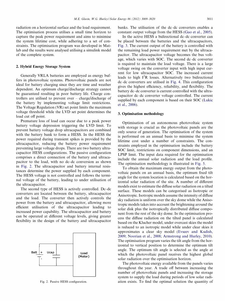
Premature loss of load can occur due to a peak powerbattery voltage depression triggering the LVD limit. Toprevent battery voltage drop ultracapacitors are combinedwith the battery bank to form a HESS. In the HESS thepower required during transient spikes is provided by theultracapacitor, reducing the battery power requirementpreventing large voltage drops. There are two battery ultra-capacitor HESS configurations. The passive configurationcomprises a direct connection of the battery and ultraca-pacitor to the load, with no dc–dc conversion as shownin Fig. 2. The ultracapacitor and battery internal resis-tances determine the power supplied by each component.The HESS voltage is not controlled and follows the termi-nal voltage of the battery, leading to under utilisation ofthe ultracapacitor.
The second type of HESS is actively controlled. Dc–dcconverters are located between the battery, ultracapacitorand the load. The converter then actively controls thepower from the battery and ultracapacitor, allowing moreefficient utilisation of the ultracapacitor leading toincreased power capability. The ultracapacitor and batterycan be operated at different voltage levels, giving greaterflexibility in the design of the battery and ultracapacitor
Fig. 2. Passive HESS configuration.
banks. The utilisation of the dc–dc converters enables aconstant output voltage from the HESS (Gao et al., 2005).
In the active HESS a bidirectional dc–dc converter canbe placed between the batteries and the ultracapacitors,Fig. 3. The current output of the battery is controlled withthe remaining load power requirement met by the ultraca-pacitor. The ultracapacitor voltage becomes the bus volt-age, which varies with SOC. The second dc–dc converteris required to maintain the load voltage. There is a largevoltage swing on the converter input with high input cur-rent for low ultracapacitor SOC. The increased currentleads to high I2R losses. Alternatively two bidirectionaldc–dc converters are utilised in Fig. 4. This configurationgives the highest efficiency, reliability, and flexibility. Thebattery dc–dc converter is current controlled with the ultra-capacitor dc–dc converter voltage controlled. The currentsupplied by each component is based on their SOC (Lukicet al., 2006).
3. Optimisation methodology
Optimisation of an autonomous photovoltaic systemwith storage is crucial as the photovoltaic panels are theonly source of generation. The optimisation of the systemis performed on an annual basis to minimise the systemlifetime cost under a number of constraints. The con-straints employed in the optimisation include the batterySOC limit, restrictions on component dimensions, and anLPSP limit. The input data required for the optimisationinclude the annual solar radiation and the load profile.The optimisation methodology is illustrated in Fig. 5.
To obtain the maximum energy output from the photo-voltaic panels on an annual basis, the optimum fixed tiltangle for the system location is calculated based on the hor-izontal solar radiation of the site. A number of differentmodels exist to estimate the diffuse solar radiation on a tiltedsurface. These models can be categorised as Isotropic orAnisotropic. Isotropic models assume the intensity of diffusesky radiation is uniform over the sky dome while the Aniso-tropic models takes into account the brightening around thesolar disk plus the isotropically distributed diffuse compo-nent from the rest of the sky dome. In the optimisation pro-cess the diffuse radiation on the tilted panel is calculatedbased on the Klucher model, under overcast skies the modelis reduced to an isotropic model while under clear skies itapproximates a clear sky model (Evseev and Kudish,2009; Noorian et al., 2008; Armstrong and Hurley, 2010).The optimisation program varies the tilt angle from the hor-izontal to vertical position to determine the optimum tiltangle. The optimum tilt angle is selected as the angle atwhich the photovoltaic panel receives the highest globalsolar radiation over the optimisation horizon.
The photovoltaic energy available from the panels variesthroughout the year. A trade off between increasing thenumber of photovoltaic panels and increasing the storagesystem to supply the load during periods of low solar radi-ation exists. To find the optimal solution the quantity of
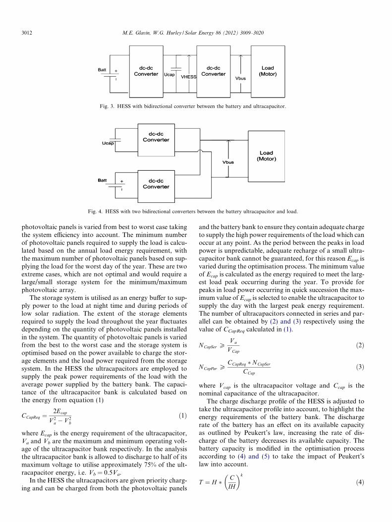
Fig. 3. HESS with bidirectional converter between the battery and ultracapacitor.
Fig. 4. HESS with two bidirectional converters between the battery ultracapacitor and load.
3012 M.E. Glavin, W.G. Hurley / Solar Energy 86 (2012) 3009–3020
photovoltaic panels is varied from best to worst case takingthe system efficiency into account. The minimum numberof photovoltaic panels required to supply the load is calcu-lated based on the annual load energy requirement, withthe maximum number of photovoltaic panels based on sup-plying the load for the worst day of the year. These are twoextreme cases, which are not optimal and would require alarge/small storage system for the minimum/maximumphotovoltaic array.
The storage system is utilised as an energy buffer to sup-ply power to the load at night time and during periods oflow solar radiation. The extent of the storage elementsrequired to supply the load throughout the year fluctuatesdepending on the quantity of photovoltaic panels installedin the system. The quantity of photovoltaic panels is variedfrom the best to the worst case and the storage system isoptimised based on the power available to charge the stor-age elements and the load power required from the storagesystem. In the HESS the ultracapacitors are employed tosupply the peak power requirements of the load with theaverage power supplied by the battery bank. The capaci-tance of the ultracapacitor bank is calculated based onthe energy from equation (1)
CCapReq ¼2Ecap
V 2a � V 2
b
ð1Þ
where Ecap is the energy requirement of the ultracapacitor,Va and Vb are the maximum and minimum operating volt-age of the ultracapacitor bank respectively. In the analysisthe ultracapacitor bank is allowed to discharge to half of itsmaximum voltage to utilise approximately 75% of the ult-racapacitor energy, i.e. Vb = 0.5Va.
In the HESS the ultracapacitors are given priority charg-ing and can be charged from both the photovoltaic panels
and the battery bank to ensure they contain adequate chargeto supply the high power requirements of the load which canoccur at any point. As the period between the peaks in loadpower is unpredictable, adequate recharge of a small ultra-capacitor bank cannot be guaranteed, for this reason Ecap isvaried during the optimisation process. The minimum valueof Ecap is calculated as the energy required to meet the larg-est load peak occurring during the year. To provide forpeaks in load power occurring in quick succession the max-imum value of Ecap is selected to enable the ultracapacitor tosupply the day with the largest peak energy requirement.The number of ultracapacitors connected in series and par-allel can be obtained by (2) and (3) respectively using thevalue of CCapReq calculated in (1).
NCapSer PV a
V Capð2Þ
NCapPar PCCapReq � N CapSer
CCapð3Þ
where Vcap is the ultracapacitor voltage and Ccap is thenominal capacitance of the ultracapacitor.
The charge discharge profile of the HESS is adjusted totake the ultracapacitor profile into account, to highlight theenergy requirements of the battery bank. The dischargerate of the battery has an effect on its available capacityas outlined by Peukert’s law, increasing the rate of dis-charge of the battery decreases its available capacity. Thebattery capacity is modified in the optimisation processaccording to (4) and (5) to take the impact of Peukert’slaw into account.
T ¼ H � CIH
� �k
ð4Þ
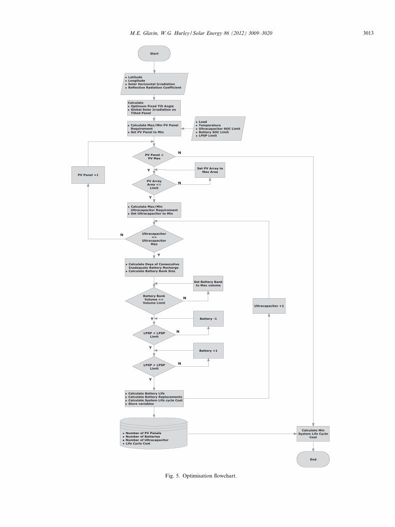
Fig. 5. Optimisation flowchart.
M.E. Glavin, W.G. Hurley / Solar Energy 86 (2012) 3009–3020 3013
3014 M.E. Glavin, W.G. Hurley / Solar Energy 86 (2012) 3009–3020
AhPeuk ¼ IT ð5Þwhere H is the rated discharge time in hours, C is the ratedcapacity at the discharge rate in ampere hours, I is the ac-tual discharge current in amps, T is the actual time to dis-charge the battery in hours, k is Peukert’s constant which isspecified by the manufacturer, typically in the range 1.1–1.3for lead acid batteries, and AhPeuk is the adjusted batterycapacity (Cugnet et al., 2010).
Traditionally in photovoltaic systems the size of the bat-tery bank is determined based on the daily load require-ment and the number of Days of Autonomy (Lead acidbattery guide for standalone photovoltaic systems, 1999).The Days of Autonomy outlines the number of days thatthe photovoltaic system can deliver full power to the loadfrom the battery bank without charge from the photovol-taic panels, utilised to ensure the load can be maintainedduring rainy and cloudy periods.
The photovoltaic panel is the only charging source forthe battery. In the proposed optimisation process the bat-tery bank is calculated for each of the photovoltaic paneland ultracapacitor combinations. The number of seriesconnected batteries is calculated in equation (6)
NBattSer ¼V Sys
V Battð6Þ
where VSys and VBatt are the system and battery voltagerespectively. The accessible battery energy in the HESS islimited depending on the SOC limit implemented in the sys-tem as given in equation (7)
EBatt ¼ V Batt � AhBatt � ð1� SOCÞ ð7Þ
where AhBatt is the nominal battery capacity. The charge/discharge profile of the battery bank is analysed to deter-mine the number of consecutive days when adequate pho-tovoltaic power is not available to fully recharge thebattery bank. This value is utilised to calculate the initialnumber of parallel batteries required as given in equation(8)
NBattPar ¼MaxDailyDischarge
EBatt
� �� DayInadChar ð8Þ
where MaxDailyDischarge is the maximum energy dis-charged by the battery in one day. DayInadChar is thenumber of consecutive days the battery does not maintainfull SOC. DayInadChar is calculated in the optimisationprogram by comparing thecharge/discharge profileto/fromthe battery bank over the optimisation horizon. This valueis set to one where the battery is fully recharged every day.Both these variables are dependent on the photovoltaic ar-ray size.
A range of constraints can be implemented in the opti-misation process. Constraints on the volume of the compo-nents in the system, and the LPSP are employed. Thevolume constraint allows restrictions on the available spacefor the storage elements and/or the photovoltaic panels tobe taken into account when designing the system.
The LPSP is a power system reliability assessment.When the LPSP is equal to 1, the demand is never satisfiedand a system redesign is required. A LPSP equal to 0,means the demand is satisfied at all times, which dependingof the criticality of the load may result in overdesign of thesystem with increased cost. The LPSP is calculated byequation (9)
LPSP ¼ 1
T
Z T
1
ððP PV þ P StorageÞ < P LoadÞ ð9Þ
where PPV, PStorage, and PLoad are the photovoltaic, storage,and load power respectively. T is the time horizon overwhich the optimisation is performed, 8760 for time horizonof 1 year (Borowy and Salameh, 1996). In Ireland, Eirgridthe transmission system operators utilise a statistical indica-tor Loss of Load Expectation (LOLE) with an accepted gen-eration adequacy of 8 h LOLE (http://www.eirgrid.com/media/Winter%20Outlook%202010_11.pdf). ESB Net-works, the Irish distribution system operators, utilise theinternational measure System Average Interruption Dura-tion Index (SAIDI), the average duration of interruptionfor all customers during the year. The commission for en-ergy regulation sets the SAIDI target for ESB networks,the target was set at 152.3 min in 2010 and reduced to141.1 min in 2011 (http://www.cer.ie/en/electricity-distribu-tion-network-decision-documents.aspx?article=0b278e96-80f5-43e1-80ab-b23423c3c34c).
The lifetime of each of the components in the systemneeds to be determined in calculating the system lifetimecost. Photovoltaic panels are taken to have a lifetime of20 years, set as the system lifetime. Ultracapacitors are notreplaced during this time as they have a cycle life of greaterthan 500,000 cycles. To determine the number of batteryreplacements required throughout the system lifetime a bat-tery life model was incorporated into the optimisation pro-cess. The battery model is an energy throughput modelbased on the model utilised in the Homer optimisation pro-gram (http://www.homerenergy.com/documents/Micro-powerSystemModelingWithHomer.pdf). The batterythroughput is the amount of energy that is cycled throughthe battery annually. The battery lifetime curve, suppliedby the manufacturer, outlines the number of charge dis-charge cycles the battery can undergo at a particular SOC.The number of charge discharge cycle’s decreases as theSOC limit is decreased. To determine the lifetime through-put from the curve the average annual SOC of the batterywas established and the number of charge discharge cycleswas calculated. The lifetime throughput is the product ofthe number of cycles, the nominal voltage, the SOC, andthe maximum capacity of the battery. The number of bat-tery replacements required during the system lifetime isdetermined by comparing the annual battery throughputand the lifetime throughput capability of the battery inequation (10).
BattReplace ¼Systemlife time
minThroughputLife
Throughputyear;BattFloat
� � ð10Þ
M.E. Glavin, W.G. Hurley / Solar Energy 86 (2012) 3009–3020 3015
where ThroughputLife is the calculated energy throughputof the battery before failure, Throughputyear is the actualenergy throughput in the year, and BattFloat is the float lifeof the battery.
The optimisation function is to minimise the system life-time cost, which is calculated from the capital and replace-ment cost of each of the system components. For simplicityonly the components that are varied during the optimisa-tion process are considered in the calculation
SystemCost ¼ CcapitalðPV þ Battery þ UltracapacitorÞþ CReplacementðBatteryÞ ð11Þ
Various combinations of photovoltaic panels, batteries,and ultracapacitor which meet constraints set out in theoptimisation process are presented, with the least costoption chosen as the optimal solution.
4. Simulation results and analysis
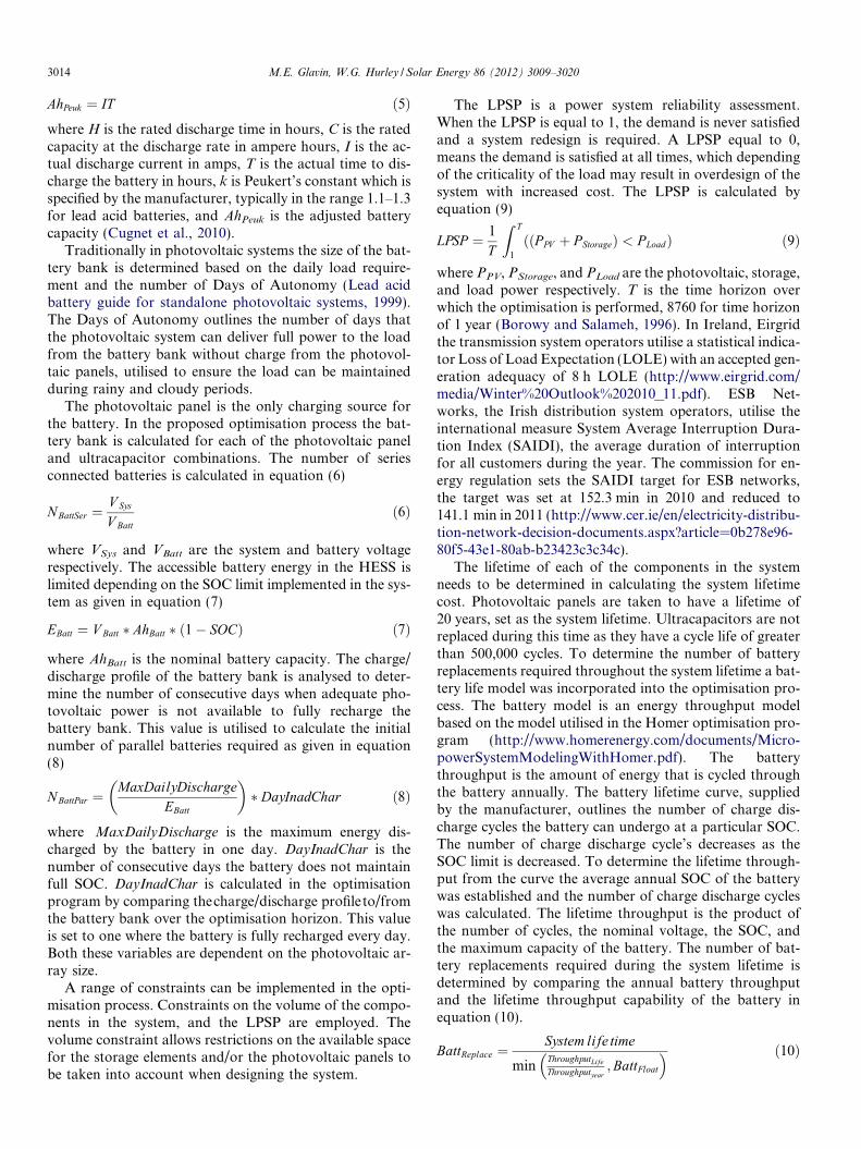
The optimisation methodology outlined in Section 3results in the determination of the number of photovoltaicpanels, the optimum tilt angle, along with the number ofVRLA batteries and ultracapacitors required in the HESS.The system voltage was taken as 12 V, with the componentvalues designed for 50 W photovoltaic panel, 18Ah VRLAbattery, and 600F Ultracapacitor. The components costutilised to calculate the system cost were €200, €70, and€45 for the photovoltaic panel, battery, and ultracapacitorrespectively. One of the required inputs to the optimisationprogram is the solar radiation on the horizontal surface. Asthe solar radiation varies over the course of the year, ayearly solar radiation profile was utilised illustrated inFig. 6, the profile was obtained from an onsite weather sta-tion located in Northern Europe (Armstrong et al., 2008).
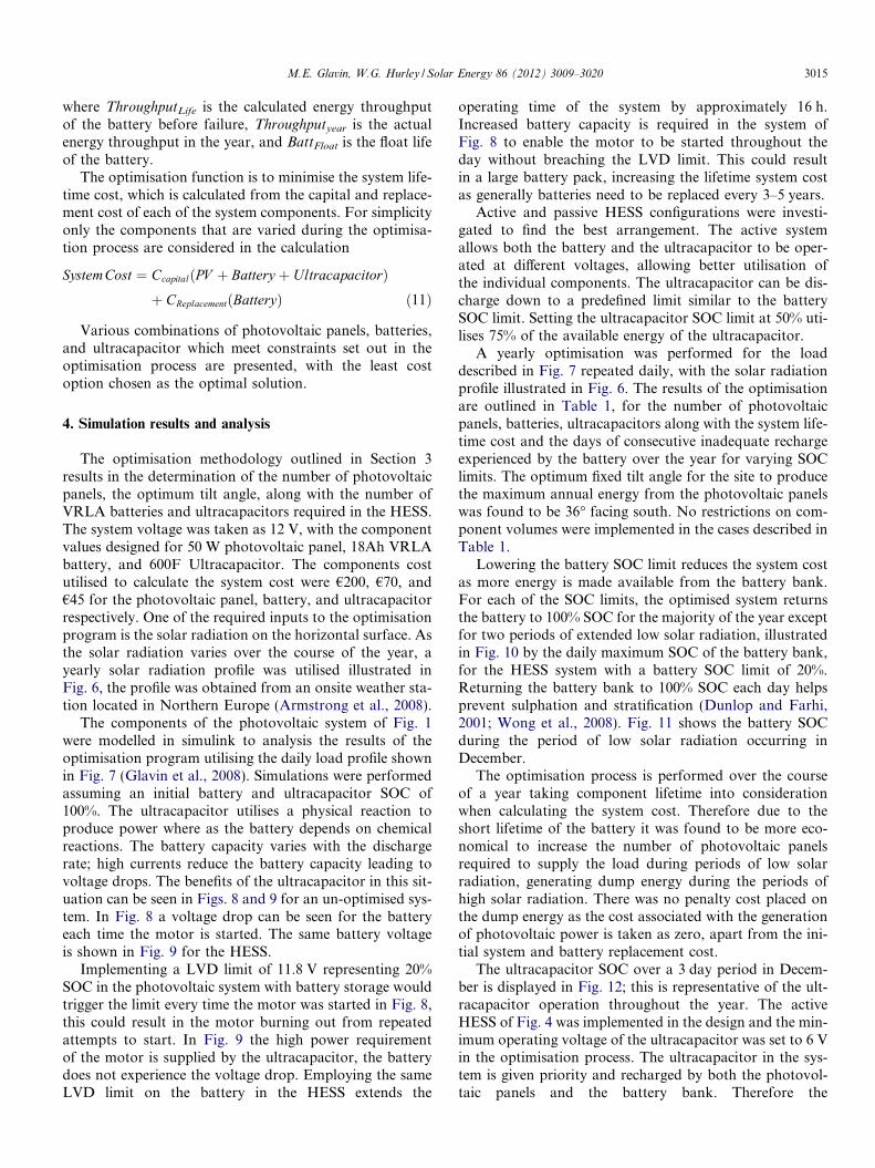
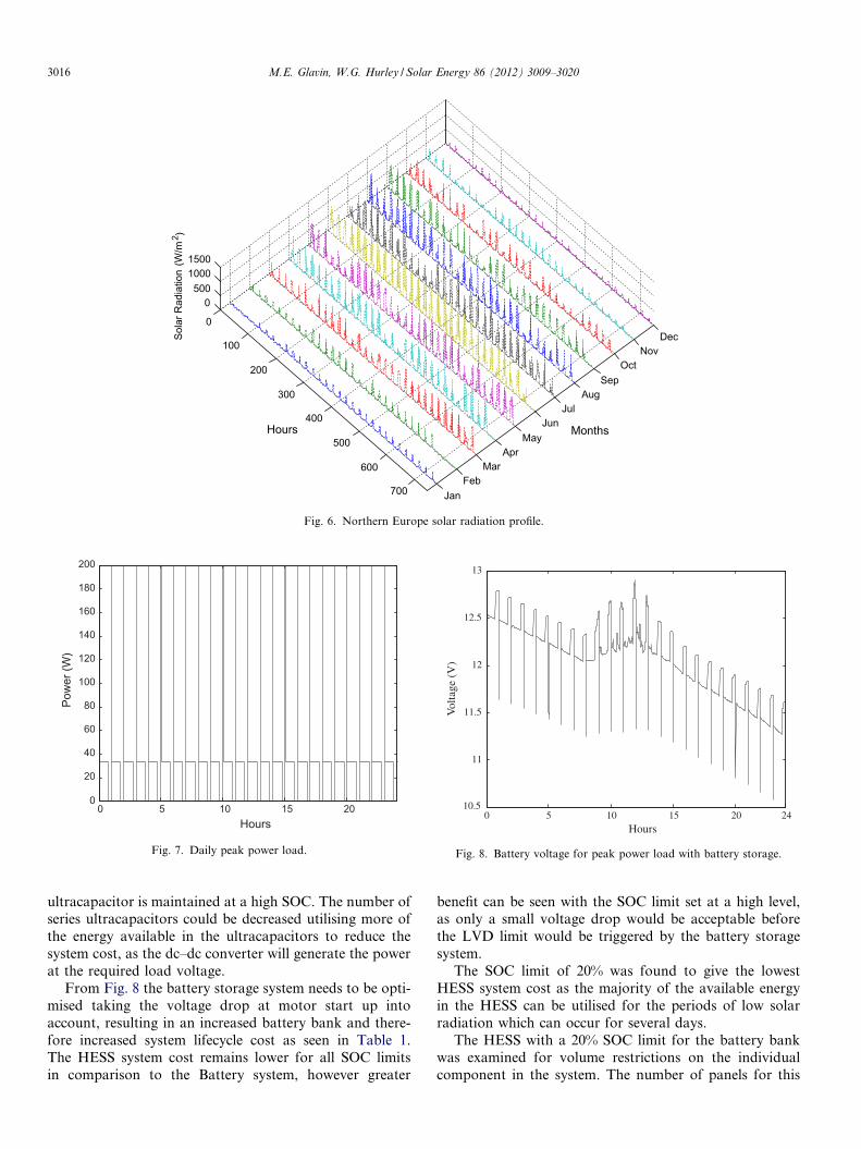
The components of the photovoltaic system of Fig. 1were modelled in simulink to analysis the results of theoptimisation program utilising the daily load profile shownin Fig. 7 (Glavin et al., 2008). Simulations were performedassuming an initial battery and ultracapacitor SOC of100%. The ultracapacitor utilises a physical reaction toproduce power where as the battery depends on chemicalreactions. The battery capacity varies with the dischargerate; high currents reduce the battery capacity leading tovoltage drops. The benefits of the ultracapacitor in this sit-uation can be seen in Figs. 8 and 9 for an un-optimised sys-tem. In Fig. 8 a voltage drop can be seen for the batteryeach time the motor is started. The same battery voltageis shown in Fig. 9 for the HESS.
Implementing a LVD limit of 11.8 V representing 20%SOC in the photovoltaic system with battery storage wouldtrigger the limit every time the motor was started in Fig. 8,this could result in the motor burning out from repeatedattempts to start. In Fig. 9 the high power requirementof the motor is supplied by the ultracapacitor, the batterydoes not experience the voltage drop. Employing the sameLVD limit on the battery in the HESS extends the
operating time of the system by approximately 16 h.Increased battery capacity is required in the system ofFig. 8 to enable the motor to be started throughout theday without breaching the LVD limit. This could resultin a large battery pack, increasing the lifetime system costas generally batteries need to be replaced every 3–5 years.
Active and passive HESS configurations were investi-gated to find the best arrangement. The active systemallows both the battery and the ultracapacitor to be oper-ated at different voltages, allowing better utilisation ofthe individual components. The ultracapacitor can be dis-charge down to a predefined limit similar to the batterySOC limit. Setting the ultracapacitor SOC limit at 50% uti-lises 75% of the available energy of the ultracapacitor.
A yearly optimisation was performed for the loaddescribed in Fig. 7 repeated daily, with the solar radiationprofile illustrated in Fig. 6. The results of the optimisationare outlined in Table 1, for the number of photovoltaicpanels, batteries, ultracapacitors along with the system life-time cost and the days of consecutive inadequate rechargeexperienced by the battery over the year for varying SOClimits. The optimum fixed tilt angle for the site to producethe maximum annual energy from the photovoltaic panelswas found to be 36� facing south. No restrictions on com-ponent volumes were implemented in the cases described inTable 1.
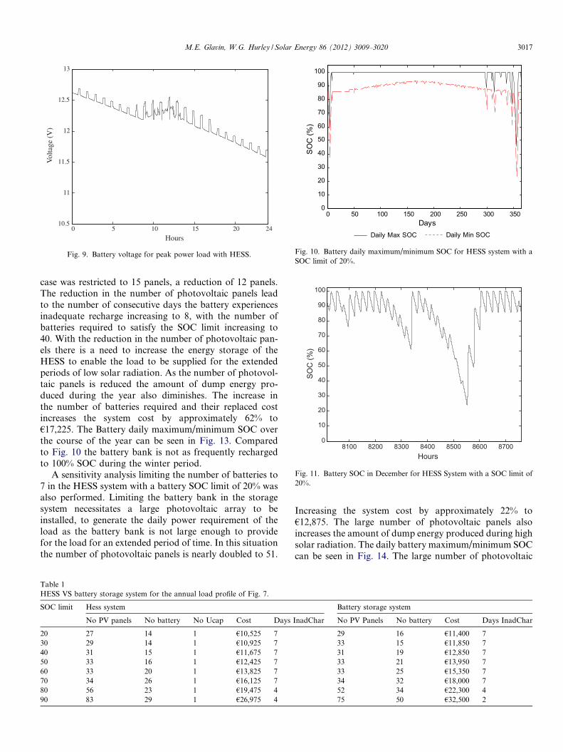
Lowering the battery SOC limit reduces the system costas more energy is made available from the battery bank.For each of the SOC limits, the optimised system returnsthe battery to 100% SOC for the majority of the year exceptfor two periods of extended low solar radiation, illustratedin Fig. 10 by the daily maximum SOC of the battery bank,for the HESS system with a battery SOC limit of 20%.Returning the battery bank to 100% SOC each day helpsprevent sulphation and stratification (Dunlop and Farhi,2001; Wong et al., 2008). Fig. 11 shows the battery SOCduring the period of low solar radiation occurring inDecember.
The optimisation process is performed over the courseof a year taking component lifetime into considerationwhen calculating the system cost. Therefore due to theshort lifetime of the battery it was found to be more eco-nomical to increase the number of photovoltaic panelsrequired to supply the load during periods of low solarradiation, generating dump energy during the periods ofhigh solar radiation. There was no penalty cost placed onthe dump energy as the cost associated with the generationof photovoltaic power is taken as zero, apart from the ini-tial system and battery replacement cost.
The ultracapacitor SOC over a 3 day period in Decem-ber is displayed in Fig. 12; this is representative of the ult-racapacitor operation throughout the year. The activeHESS of Fig. 4 was implemented in the design and the min-imum operating voltage of the ultracapacitor was set to 6 Vin the optimisation process. The ultracapacitor in the sys-tem is given priority and recharged by both the photovol-taic panels and the battery bank. Therefore the
0
100
200
300
400
500
600
700 JanFeb
MarApr
MayJun
JulAug
SepOct
NovDec
0500
10001500
MonthsHours
Sola
r Rad
iatio
n 2 )
(W/m
Fig. 6. Northern Europe solar radiation profile.
0 5 10 15 200
20
40
60
80
100
120
140
160
180
200
Hours
Pow
er (W
)
Fig. 7. Daily peak power load.
0 5 10 15 20 2410.5
11
11.5
12
12.5
13
Hours
Vol
tage
(V
)
Fig. 8. Battery voltage for peak power load with battery storage.
3016 M.E. Glavin, W.G. Hurley / Solar Energy 86 (2012) 3009–3020
ultracapacitor is maintained at a high SOC. The number ofseries ultracapacitors could be decreased utilising more ofthe energy available in the ultracapacitors to reduce thesystem cost, as the dc–dc converter will generate the powerat the required load voltage.
From Fig. 8 the battery storage system needs to be opti-mised taking the voltage drop at motor start up intoaccount, resulting in an increased battery bank and there-fore increased system lifecycle cost as seen in Table 1.The HESS system cost remains lower for all SOC limitsin comparison to the Battery system, however greater
benefit can be seen with the SOC limit set at a high level,as only a small voltage drop would be acceptable beforethe LVD limit would be triggered by the battery storagesystem.
The SOC limit of 20% was found to give the lowestHESS system cost as the majority of the available energyin the HESS can be utilised for the periods of low solarradiation which can occur for several days.
The HESS with a 20% SOC limit for the battery bankwas examined for volume restrictions on the individualcomponent in the system. The number of panels for this
0 5 10 15 20 2410.5
11
11.5
12
12.5
13
Hours
Vol
tage
(V
)
Fig. 9. Battery voltage for peak power load with HESS.
0 50 100 150 200 250 300 3500
10
20
30
40
50
60
70
80
90
100
Days
SO
C (%
)
Daily Max SOC Daily Min SOC
Fig. 10. Battery daily maximum/minimum SOC for HESS system with aSOC limit of 20%.
8100 8200 8300 8400 8500 8600 87000
10
20
30
40
50
60
70
80
90
100
Hours
SOC
(%)
Fig. 11. Battery SOC in December for HESS System with a SOC limit of20%.
M.E. Glavin, W.G. Hurley / Solar Energy 86 (2012) 3009–3020 3017
case was restricted to 15 panels, a reduction of 12 panels.The reduction in the number of photovoltaic panels leadto the number of consecutive days the battery experiencesinadequate recharge increasing to 8, with the number ofbatteries required to satisfy the SOC limit increasing to40. With the reduction in the number of photovoltaic pan-els there is a need to increase the energy storage of theHESS to enable the load to be supplied for the extendedperiods of low solar radiation. As the number of photovol-taic panels is reduced the amount of dump energy pro-duced during the year also diminishes. The increase inthe number of batteries required and their replaced costincreases the system cost by approximately 62% to€17,225. The Battery daily maximum/minimum SOC overthe course of the year can be seen in Fig. 13. Comparedto Fig. 10 the battery bank is not as frequently rechargedto 100% SOC during the winter period.
A sensitivity analysis limiting the number of batteries to7 in the HESS system with a battery SOC limit of 20% wasalso performed. Limiting the battery bank in the storagesystem necessitates a large photovoltaic array to beinstalled, to generate the daily power requirement of theload as the battery bank is not large enough to providefor the load for an extended period of time. In this situationthe number of photovoltaic panels is nearly doubled to 51.
Table 1HESS VS battery storage system for the annual load profile of Fig. 7.
SOC limit Hess system
No PV panels No battery No Ucap Cost Days
20 27 14 1 €10,525 730 29 14 1 €10,925 740 31 15 1 €11,675 750 33 16 1 €12,425 760 33 20 1 €13,825 770 34 26 1 €16,125 780 56 23 1 €19,475 490 83 29 1 €26,975 4
Increasing the system cost by approximately 22% to€12,875. The large number of photovoltaic panels alsoincreases the amount of dump energy produced during highsolar radiation. The daily battery maximum/minimum SOCcan be seen in Fig. 14. The large number of photovoltaic
Battery storage system
InadChar No PV Panels No battery Cost Days InadChar
29 16 €11,400 733 15 €11,850 731 19 €12,850 733 21 €13,950 733 25 €15,350 734 32 €18,000 752 34 €22,300 475 50 €32,500 2

8020 8030 8040 8050 8060 8070 80800
10
20
30
40
50
60
70
80
90
100
Hours
SOC
(%)
Fig. 12. Ultracapacitor SOC for 3 days in December for HESS systemwith a SOC limit of 20.
0 50 100 150 200 250 300 3500
10
20
30
40
50
60
70
80
90
100
Days
SO
C (%
)
Daily Max SOC Daily Min SOC
Fig. 13. Battery daily maximum/minimum SOC for photovoltaic panelsensitivity analysis.
0 50 100 150 200 250 300 3500
10
20
30
40
50
60
70
80
90
100
Days
SO
C (%
)
Daily Max SOC Daily Min SOC
Fig. 14. Battery daily maximum/minimum SOC for battery bank volumerestriction analysis.
3018 M.E. Glavin, W.G. Hurley / Solar Energy 86 (2012) 3009–3020
panels returns the battery array to 100% SOC for the major-ity of the year but the reduction in the number of batteriesmeans the batteries are discharged to a lower SOC.Comparing the lifetime system cost of both sensitivity anal-ysis highlights further the impact the battery bank has onthe lifetime cost due to number of battery replacementsrequired during this period.
The system size and lifecycle cost can be reduced if theloads supplied were non-critical and an LPSP of greaterthan zero is considered. Throughout the majority of theyear the batteries in the system are maintained at a highSOC in the HESS. If the system was allowed to drop theload for a short period of time during prolonged periodsof low solar radiation which only occurs twice during theyear the battery bank could be reduced. Setting the LPSPto allow 8 h loss of load in the optimisation process reducesthe system cost by approximately 4% to €10,175. This isachieved by reducing the size of the battery bank, a loss
of load of approximately 4 h was observed during the per-iod of low solar radiation at the end of the year.
The benefit of the HESS can be seen in Table 1 for amotor load that is repeatedly started throughout the day.This will not be the case for all applications. The load pro-file of Fig. 7 was adapted for two situations, a motorstarted daily at 4am for 45 min, and a motor started dailyat 5pm for 45 min. The results of the optimisation are out-lined in Tables 2 and 3 for the profile of the motor startedat 4am and 5pm respectively. The results of Tables 2 and 3are similar, and follow the trend of those in Table 1. Theaddition of the ultracapacitor reduces the system lifetimecost, with the greatest benefit seen when the battery SOClimit is high.
5. Conclusions
A sustainable energy system consisting of a photovoltaicarray with a battery ultracapacitor HESS to supply a non-grid connected load was introduced. The impact of includingthe ultracapacitor in the photovoltaic system was analysed.The batteries and ultracapacitors complement each otherin terms of their power and energy densities.
Electrical loads that contain motors can have powerspikes of between three and seven times their rated wattageat start-up, while loads requiring large capacitors to becharged at start up can result in a power surge up to threetimes their rated wattage.
A DC system was analysed in this paper but the sameprincipals apply to AC systems. In an AC system the inver-ter must be sized to take into account the starting powerrequirement of the load, with the battery bank being sizedto handle the voltage drop due to the high current surge.Otherwise the drop in voltage could cause the inverter toshut down.
The battery bank supplies power to the load throughchemical reactions, with the capacity of the battery
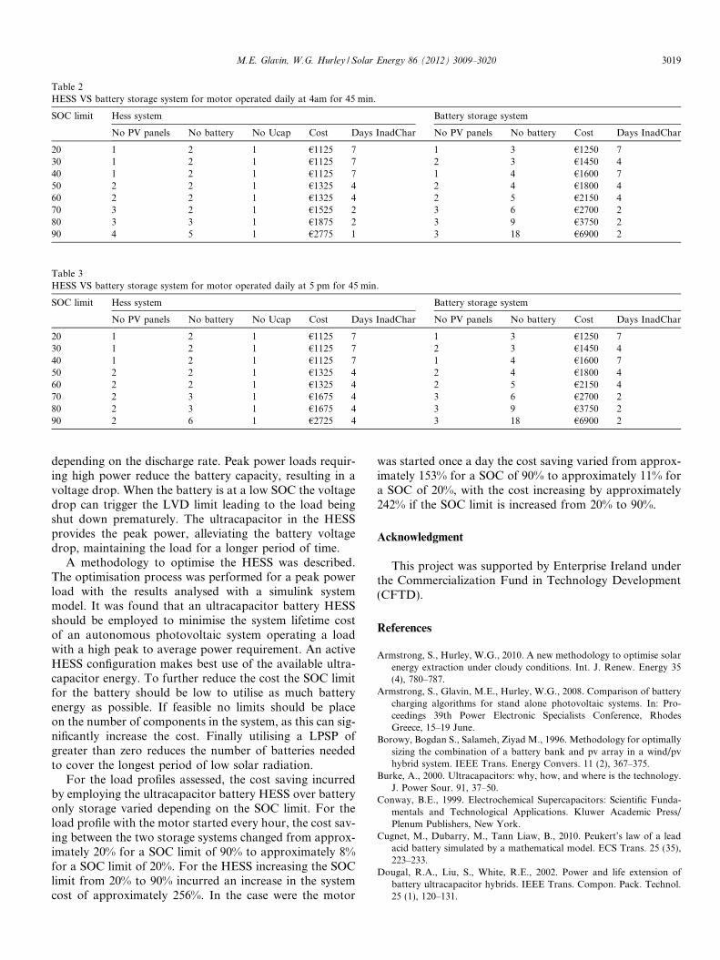
Table 2HESS VS battery storage system for motor operated daily at 4am for 45 min.
SOC limit Hess system Battery storage system
No PV panels No battery No Ucap Cost Days InadChar No PV panels No battery Cost Days InadChar
20 1 2 1 €1125 7 1 3 €1250 730 1 2 1 €1125 7 2 3 €1450 440 1 2 1 €1125 7 1 4 €1600 750 2 2 1 €1325 4 2 4 €1800 460 2 2 1 €1325 4 2 5 €2150 470 3 2 1 €1525 2 3 6 €2700 280 3 3 1 €1875 2 3 9 €3750 290 4 5 1 €2775 1 3 18 €6900 2
Table 3HESS VS battery storage system for motor operated daily at 5 pm for 45 min.
SOC limit Hess system Battery storage system
No PV panels No battery No Ucap Cost Days InadChar No PV panels No battery Cost Days InadChar
20 1 2 1 €1125 7 1 3 €1250 730 1 2 1 €1125 7 2 3 €1450 440 1 2 1 €1125 7 1 4 €1600 750 2 2 1 €1325 4 2 4 €1800 460 2 2 1 €1325 4 2 5 €2150 470 2 3 1 €1675 4 3 6 €2700 280 2 3 1 €1675 4 3 9 €3750 290 2 6 1 €2725 4 3 18 €6900 2
M.E. Glavin, W.G. Hurley / Solar Energy 86 (2012) 3009–3020 3019
depending on the discharge rate. Peak power loads requir-ing high power reduce the battery capacity, resulting in avoltage drop. When the battery is at a low SOC the voltagedrop can trigger the LVD limit leading to the load beingshut down prematurely. The ultracapacitor in the HESSprovides the peak power, alleviating the battery voltagedrop, maintaining the load for a longer period of time.
A methodology to optimise the HESS was described.The optimisation process was performed for a peak powerload with the results analysed with a simulink systemmodel. It was found that an ultracapacitor battery HESSshould be employed to minimise the system lifetime costof an autonomous photovoltaic system operating a loadwith a high peak to average power requirement. An activeHESS configuration makes best use of the available ultra-capacitor energy. To further reduce the cost the SOC limitfor the battery should be low to utilise as much batteryenergy as possible. If feasible no limits should be placeon the number of components in the system, as this can sig-nificantly increase the cost. Finally utilising a LPSP ofgreater than zero reduces the number of batteries neededto cover the longest period of low solar radiation.
For the load profiles assessed, the cost saving incurredby employing the ultracapacitor battery HESS over batteryonly storage varied depending on the SOC limit. For theload profile with the motor started every hour, the cost sav-ing between the two storage systems changed from approx-imately 20% for a SOC limit of 90% to approximately 8%for a SOC limit of 20%. For the HESS increasing the SOClimit from 20% to 90% incurred an increase in the systemcost of approximately 256%. In the case were the motor
was started once a day the cost saving varied from approx-imately 153% for a SOC of 90% to approximately 11% fora SOC of 20%, with the cost increasing by approximately242% if the SOC limit is increased from 20% to 90%.
Acknowledgment
This project was supported by Enterprise Ireland underthe Commercialization Fund in Technology Development(CFTD).
References
Armstrong, S., Hurley, W.G., 2010. A new methodology to optimise solarenergy extraction under cloudy conditions. Int. J. Renew. Energy 35(4), 780–787.
Armstrong, S., Glavin, M.E., Hurley, W.G., 2008. Comparison of batterycharging algorithms for stand alone photovoltaic systems. In: Pro-ceedings 39th Power Electronic Specialists Conference, RhodesGreece, 15–19 June.
Borowy, Bogdan S., Salameh, Ziyad M., 1996. Methodology for optimallysizing the combination of a battery bank and pv array in a wind/pvhybrid system. IEEE Trans. Energy Convers. 11 (2), 367–375.
Burke, A., 2000. Ultracapacitors: why, how, and where is the technology.J. Power Sour. 91, 37–50.
Conway, B.E., 1999. Electrochemical Supercapacitors: Scientific Funda-mentals and Technological Applications. Kluwer Academic Press/Plenum Publishers, New York.
Cugnet, M., Dubarry, M., Tann Liaw, B., 2010. Peukert’s law of a leadacid battery simulated by a mathematical model. ECS Trans. 25 (35),223–233.
Dougal, R.A., Liu, S., White, R.E., 2002. Power and life extension ofbattery ultracapacitor hybrids. IEEE Trans. Compon. Pack. Technol.25 (1), 120–131.
3020 M.E. Glavin, W.G. Hurley / Solar Energy 86 (2012) 3009–3020
Dunlop, J.P., Farhi, B.N., 2001. Recommendations for maximisingbattery life in photovoltaic systems: a review of lessons learned. In:Proceedings of Forum 2001 Solar Energy: The Power to Choose,Washington DC, 21–25 April.
Ekren, B.Y., Ekren, O., 2009. Simulation based size optimization of a pv/wind hybrid energy conversion system with battery storage undervarious load and auxiliary energy conditions. Appl. Energy 86, 1387–1394.
European photovoltaic industry association. 2015. Global Market Out-look For Photovoltaics Until 2015.
Evseev, E.G., Kudish, A.I., 2009. The assessment of different models topredict the global solar radiation on a surface tilted to the south. Sol.Energy 83 (3), 377–388.
Gao, L., Dougal, R.A., Liu, S., 2005. Power enhancement of an activelycontrolled battery ultracapacitor hybrid. IEEE Trans. Power Electr. 20(1), 236–243.
Glavin, M.E., Chan, P.K.W., Armstrong, S., Hurley, W.G., 2008. Astandalone photovoltaic supercapacitor battery hybrid energy storagesystem. In: Proceedings 13th Power Electronics and Motion ControlConference, Poland, 1–3 September, pp. 1688–1695.
Hontoria, L., Aguilera, J., Zufiria, P., 2005. A new approach for sizingstand alone photovoltaic systems based in neural networks. Sol.Energy 78, 314–319.
http://www.cer.ie/en/electricity-distribution-network-decision-documents.aspx?article=0b278e96-80f5-43e1-80ab-b23423c3c34c.
http://www.eirgrid.com/media/Winter%20Outlook%202010_11.pdf.http://www.homerenergy.com/documents/MicropowerSystemModeling
WithHomer.pdf.
Koutroulis, E., Kolokotsa, D., Potirakis, A., Kalaitzakis, K., 2006.Methodology for optimal sizing of stand alone photovoltaic/windgenerator system using genetic algorithms. Sol. Energy 80, 1072–1088.
Kuperman, A., Aharon, I., 2011. Battery ultracapacitor hybrids for pulsedcurrent loads a review. Renew. Sustain. Energy Rev. 15 (2), 981–992.
Lead acid battery guide for standalone photovoltaic systems, 1999. In:IEA International Energy Agency, Report IEA – PVPS 3–06:1999,December.
Liu, S., Dougal, R.A., Solodovnik, E.V., 2005. Design of autonomousphotovoltaic relay station. IEEE Proc-Gener. Transm. Distrib. 152 (6),745–754.
Lukic, S.M., Wirasingha, S.G., Rodriguez, F., Cao, J., Emadi, A., 2006.Power management of an ultracapacitor/battery hybrid energy storagesystem in an HEV. In: IEEE Vehicle Power and Propulsion Confer-ence, 6–8 September.
Noorian, A.M., Moradi, I., Kamali, G.A., 2008. Evaluation of 12 modelsto estimate hourly diffuse irradiation in inclined surfaces. Renew.Energy 33 (6), 1406–1412.
Van Voorden, A.M., Elizondo, L.M.R., Paap, G.C., Verboomen, J., VanDer Sluis, L., 2007. The application of supercapacitors to relievebattery storage systems in autonomous renewable energy systems.IEEE Lausanne Power Tech. 23, 479–484.
Vosen, S.R., Keller, J.O., 1999. Hybrid energy storage for stand aloneelectric power systems: optimisation of system performance and costthrough control strategies. Int. J. Hydrogen Energy 24, 1139–1156.
Wong, Y.S., Hurley, W.G., Wolfle, W.H., 2008. Charge regimes for valveregulated lead acid batteries: performance overview inclusive oftemperature compensation. J. Power Sour. 183 (2), 783–791.