optics and lasers in engineering
TRANSCRIPT

Optics and Lasers in Engineering 52 (2014) 195–200
Contents lists available at ScienceDirect
Optics and Lasers in Engineering
0143-81http://d
n CorrE-m
journal homepage: www.elsevier.com/locate/optlaseng
High-quality fringe pattern generation using binary patternoptimization through symmetry and periodicity
Junfei Dai a, Beiwen Li b, Song Zhang b,n
a Mathematics Department, Zhejiang University, Zhejiang 310027, Chinab Mechanical Engineering Department, Iowa State University, Ames, IA 50011, United States
a r t i c l e i n f o
Article history:Received 30 March 2013Received in revised form23 May 2013Accepted 20 June 2013Available online 9 July 2013
Keywords:Fringe analysis3D shape measurementDitheringBinary defocusingOptimization
66/$ - see front matter & 2013 Elsevier Ltd. Ax.doi.org/10.1016/j.optlaseng.2013.06.010
esponding author. Tel.: +1 515 294 0723; fax:ail address: [email protected] (S. Zhang).
a b s t r a c t
This paper presents a novel method to construct binary patterns for high-quality 3D shape measurement.The algorithm generates small patches using symmetry and periodicity, randomly initializes each pixels,optimizes the small patches through mutations, and finally tiles the optimized patches into full sizepatterns using again symmetry and periodicity. We will demonstrate that the proposed method canachieve substantial phase quality improvements over the dithering techniques for different amounts ofdefocusing.
& 2013 Elsevier Ltd. All rights reserved.
1. Introduction
In the past decade, digital fringe projection (DFP) techniqueshave been increasingly used for high-quality 3D shape measure-ment due to its flexibility [1], but have the major limitations ofspeed bottleneck (typically 120 Hz) and projection nonlinearity.Our recently proposed binary defocusing technique [2,3] hasdemonstrated the great promise of overcoming the limitations ofconventional DFP technique. Yet, the high-frequency harmonicssubstantially influence the measurement quality if the measure-ment depth range is large and the required measurement speed ishigh [4]. Xu et al. [4] proposed a passive error compensationmethod to alleviate the high-frequency harmonic influences. Thistechnique has demonstrated its success if high-quality calibrationis performed pixel by pixel. However, the improvement is ratherlimited if the fringe stripes are wide.
Actively modulating the squared binary patterns has beenextensively studied and shows even greater improvements.Among these methods, the pulse width modulation (PWM)techniques [5–8] change the squared binary patterns in onedimension. These techniques either shift the high-order harmonicsfurther away from fundamentally frequency such that they areeasier to be suppressed by defocusing [5], or theoretically elim-inate those most influential harmonics [6–8]. These techniquesindeed could improve measurement quality. However, due to the
ll rights reserved.
+1 515 294 3261.
discrete nature of fringe generation, the PWM techniques can onlygenerate high-quality sinusoidal fringe patterns when the fringestripes are narrow [9]. PWM techniques only modulate thepatterns in 1D, and thus their ultimate enhancements are ratherlimited. 2D area modulation techniques [10] could further improvethe quality. However, it is difficult for all these techniques togenerate high quality fringe pattern when fringe stripes are wide.
It turns out that the dithering techniques [11–16], developed torepresent high-bit number images with binary images, couldimprove fringe quality for wider fringe stripes [17]. These techni-ques endeavor to maintain low-frequency information such thatthe overall image appears to be the original once a low-pass filteris applied. However, we found that if the fringe stripes are narrow,the improvement was rather small. Unfortunately, for 3D shapemeasurement, high-frequency sinusoidal fringe patterns areusually desirable since they provide better measurement quality.Optimizing dithered patterns could improve the fringe quality. Wehave recently developed a genetic algorithm to drastically improvethe phase quality when fringe stripes are narrow [18]. However,this technique is very time consuming (taking hours), and some-times the algorithm does not converge if the initial genes arenot good.
The objective of all these optimization techniques is to obtainthe best fit of the binary patterns to the ideal sinusoidal pattern. Inother words, the optimized binary patterns should be as close aspossible to the ideal sinusoidal patterns after applying Gaussiansmoothing. Mathematically, we are minimizing the functional
minB;G
‖Iðx; yÞ−Gðx; yÞ⊗Bðx; yÞ‖F ð1Þ

J. Dai et al. / Optics and Lasers in Engineering 52 (2014) 195–200196
where ‖ � ‖F is the Frobenius norm, Iðx; yÞ is the ideal sinusoidalintensity pattern, Gðx; yÞ is a 2D Gaussian kernel, Bðx; yÞ is thedesired 2D binary pattern, and ⊗ represents convolution. Unfortu-nately, the problem is Non-deterministic Polynomial-time (NP)hard, making it impractical to solve the problem mathematically.Furthermore, the desired pattern should perform well for differentamounts of defocusing (i.e., varying Gðx; yÞ), making the problemeven more complex.
This paper presents a method to conquer these challenges. Thistechnique comes from our two observations: (1) the binarypatterns should be symmetric for one fringe stripe since theresultant sinusoidal patterns are symmetric, and (2) the binarypattern should be periodical in both x and y directions since thedesired sinusoidal patterns are periodical in both directions (witha period of 1 pixel for one direction). The optimization is tominimize the error between the defocused (or blurred) binarypattern and the desired ideal sinusoidal pattern. Since the ultimategoal is to generate high-quality phase for a large depth range, theproposed technique selects the fringe patterns that consistentlyperform well with different amounts of defocusing.
Section 2 explains the principle of the phase-shifting algorithmand the dithering technique. Section 3 presents the proposedframework for constructing binary patterns. Section 4 showssimulation results. Section 5 presents the experimental results.Section 6 discusses the merits and shortcomings of the proposedtechnique, and finally Section 7 summarizes this paper.
2. Principle
2.1. Three-step phase-shifting algorithm
Phase-shifting algorithms have been extensively used in opticalmetrology [19]. Typically, the more fringe patterns used, the bettermeasurement quality can be achieved. For high-speed 3D shapemeasurement, a three-step phase-shifting algorithm is usuallyadopted since it requires the minimum number of patterns tosolve for the phase uniquely point by point. Since our researchfocuses on high-speed 3D shape measurement, a simple three-step phase-shifting algorithm with a phase shift of 2π=3 was usedto test the generated patterns. Three fringe images can bedescribed as
I1ðx; yÞ ¼ I′ðx; yÞ þ I″ðx; yÞ cos ½ϕ−2π=3�; ð2Þ
I2ðx; yÞ ¼ I′ðx; yÞ þ I″ðx; yÞ cos ½ϕ�; ð3Þ
I3ðx; yÞ ¼ I′ðx; yÞ þ I″ðx; yÞ cos ½ϕþ 2π=3�: ð4Þwhere I′ðx; yÞ is the average intensity, I″ðx; yÞ the intensity modula-tion, and ϕðx; yÞ the phase to be solved for
ϕðx; yÞ ¼ tan −1
ffiffiffi3
pðI1−I3Þ
2I2−I1−I3: ð5Þ
This equation provides the wrapped phase ranging [−π; þ π) with2π discontinuities. A continuous phase map can be obtained byadopting a spatial [20] or temporal phase unwrapping algorithm.In this research, we used the temporal phase unwrapping frame-work introduced in [21].
2.2. Error-diffusion dithering technique
Compared with the Bayer-ordered dithering technique, theerror-diffusion dithering technique is more complicated butachieves higher quality. For an error-diffusion algorithm, the pixelsare quantized in a specific order, and the quantization error for thecurrent pixel is propagated forward to local unprocessed pixels
through the following equation:
~f ði; jÞ ¼ f ði; jÞ þ ∑k;l∈S
hðk; lÞeði−k; j−lÞ: ð6Þ
Here, f ði; jÞ is the original image, ~f ði; jÞ the quantized image, andeði; jÞ the quantization error: the difference between the quantizedimage pixel and the diffused image pixel. eði; jÞ is further diffusedto its neighboring pixels through a two-dimensional weightingfunction hði; jÞ, known as the diffusion kernel. There are numerouserror-diffusion dithering algorithms differing on the diffusionkernel selection. In this paper, we use one of the most accuratemethods proposed by Floyd–Steinberg, with the following diffu-sion kernel:
hði; jÞ ¼ 116
− n 73 5 1
� �ð7Þ
Here − represents the processed pixel, n represents the pixel inprocess. It should be noted that the kernel coefficients sum to one,and thus the local average value of the quantized image will beequal to the local average of the original one.
3. Binary pattern construction framework
As discussed earlier, the objective of all these optimizationtechniques is to obtain the best fit of the binary patterns to theideal sinusoidal pattern. In other words, the optimized binarypatterns should be as close as possible to the ideal sinusoidalpatterns after applying Gaussian smoothing. Mathematically, weare minimizing the functional
minB;G
‖Iðx; yÞ−Gðx; yÞ⊗Bðx; yÞ‖F : ð8Þ
This problem is NP hard, making it impractical to solve theproblem mathematically. Furthermore, the desired pattern shouldperform well for different amounts of defocusing (i.e., varyingGðx; yÞ), making the problem even more complex.
Instead of optimizing the desired fringe pattern as a whole (e.g.,800�600) as our previously proposed [18,22], we propose tooptimize a subset called binary patch, and then tile the patch togenerate the full-size patterns using symmetry and periodicity.Unlike those PWM techniques, the proposed technique belongs toarea modulation technique where the modulations occur in both xand y directions. Compared with the dithering techniques, theproposed technique strives to generate higher quality fringepatterns with narrow fringe stripes, and similar quality for broadfringe stripes. In addition, unlike the previously proposed method[18] where the optimization is performed under one defocusinglevel, the proposed method improves fringe quality for differentamounts of defocusing.
Assume that the desired sinusoidal fringe patterns vary along xdirection: the best-fit binary pattern should be symmetric along xdirection for one fringe period (T); and it should be periodic alongthe y direction. Row period, Sy, is defined as the period along ydirection. We believe that different breadths of fringe patternsrequire different optimization strategies, and thus we could utilizedifferent row periods for different breadths of fringe patterns.Instead of directly solving the best-fit NP-hard problem, wepropose to modulate a small binary patch for each fringe pattern,and then tile the patch together using symmetry and periodicity ofthe fringe pattern. The process of modulating a binary patch togenerate the whole binary pattern can be divided into thefollowing major steps:
Step1: Patch formation. This step initializes the Sy (2 to 10), anddefines the number of pixels along x direction. The patch is formedas a dimension of Sx � Sy, here Sx ¼ T=2 is one half fringe period.
J. Dai et al. / Optics and Lasers in Engineering 52 (2014) 195–200 197
Step2: Patch initialization. Randomly assign each pixel of theSx � Sy patch with 0 or 1.
Step3: Patch optimization. For each pixel in the binary patch, itsbinary status is mutated (i.e., 1 to 0 or 0 to 1). If this mutationimproves fringe quality, i.e., the intensity root-mean-square (rms)difference between the Gaussian smoothed pattern and the idealsinusoidal pattern is smaller, the mutation is regarded as a goodmutation. It should be noted that mutating one pixel will influenceits neighborhood after applying a Gaussian filter. Therefore, theoptimization is iteratively performed until the algorithm con-verges when the rms error difference for a new round of iterationsis less than 0.01%.
Step4: Patch variation. Repeat Steps 2–3 for a number of times(ranging from 50–500 times) to generate a number of goodcandidates for each Sy, a number of good patches could begenerated because of the random initialization.
Step5: Patch dimension mutation. Change Sy to another value(i.e., 2 to 10), and go to Step 2.
Step6: Patch selection. After a number of patch mutations, a setof optimized patches are generated. From these patches, the bestpatch is selected based on the following two rules: (1) phase errordoes not change drastically if a different size of Gaussian filter isapplied; and (2) the resultant phase error is consistently small.These two rules imply that the best patch under one amount ofdefocusing may not be chosen. This is one of the fundamentaldifference between our algorithm and the previously developedgenetic algorithm [18].
5 70
0.005
0.01
Filter siz
Pha
se rm
s er
ror (
rad)
Pa
Pa
Pa
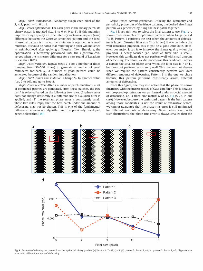
Fig. 1. Example of selecting the pattern from the optimized binary patches. (a) Pattern 1error with different amounts of defocusing.
Step7: Fringe pattern generation. Utilizing the symmetry andperiodicity properties of the fringe patterns, the desired size fringepattern was generated by tiling the best patch together.
Fig. 1 illustrates how to select the final pattern to use. Fig. 1a–cshows three examples of optimized patterns when fringe periodT¼18. Pattern 1 performs the best when the amounts of defocus-ing is larger (Gaussian filter size 11 or larger). If one considers thewell defocused projector, this might be a good candidate. How-ever, our major focus is to improve the fringe quality when theprojector is nearly focused (i.e., Gaussian filter size is small).However, this candidate does not perform well with small amountof defocusing. Therefore, we did not choose this candidate. Pattern2 depicts the smallest phase error when the filter size is 7 or 11,but does not perform consistently well. This one was not chosensince we require the pattern consistently perform well overdifferent amounts of defocusing. Pattern 3 is the one we chosebecause this pattern performs consistently across differentamounts of defocusing.
From this figure, one may also notice that the phase rms errorfluctuates with the increased size of Gaussian filter. This is becauseour proposed optimization was performed under a special amountof defocusing, i.e., a fixed size matrix G of Eq. (1) (5�5 in ourcase). However, because the optimized pattern is the best patternamong those candidates, is not the result of exhaustive search,we cannot guarantee that the phase rms error is still minimizedfor different amounts of defocusing. Nevertheless, even withsuch fluctuations, the phase rms error is always smaller than the
9 11 13
e (pixel)
ttern 1
ttern 2
ttern 3
: T¼18, Sy¼5; (b) pattern 2: T¼18, Sy¼4; (c) pattern 3: T¼18, Sy¼2; (d) phase rms

20 40 60 80 100
0.005
0.01
0.015
0.02
0.025
0.03
0.035
Fringe period T (pixel)
Pha
se rm
s er
ror (
rad)
20 40 60 80 100
2
4
6
8
10
x 10−3
Fringe period T (pixel)
Pha
se rm
s er
ror (
rad)
Error Diff.Proposed
Error Diff.Proposed
Fig. 2. Comparing the phase quality between the proposed method and the Floyd–Steinberg error-diffusion technique. (a) Gaussian filter size of 5�5 pixels and standarddeviation of 5/3 pixels; (b) Gaussian filter size of 13�13 pixels and standard deviation of 13/3 pixels.
20 40 60 80 1000.03
0.04
0.05
0.06
Fringe period T (pixel)
Pha
se rm
s er
ror (
rad)
Error Diff.Proposed
20 40 60 80 100
0.025
0.03
0.035
0.04
0.045
0.05
Fringe period T (pixel)
Pha
se rm
s er
ror (
rad)
Error Diff.Proposed
Fig. 3. Experimentally comparing the phase quality between the proposed method and the Floyd–Steinberg error-diffusion technique. (a) Nearly focused; (b) slightlydefocused.
J. Dai et al. / Optics and Lasers in Engineering 52 (2014) 195–200198
error-diffusion dithering technique, as will be shown in Figs. 2 and 3,indicating the success of the proposed method.
4. Simulations
We simulated different amounts of defocusing by applyingdifferent sizes of Gaussian filters. The smallest Gaussian filter was5�5 with a standard deviation of 5/3 pixels, and the largest was13�13 with a standard deviation of 13/3 pixels. Gaussian filtersize of 5�5 represents the case that the projector is nearlyfocused, whilst 13�13 represents the case when the projector isdefocused to a certain degree. We did not use larger filter sizes asthey will jeopardize the fringe contrast, which is not usually usedin real measurements. The phase error ΔΦ was calculated bytaking the difference between the phase obtained from thesmoothed binary patterns, Φb, and the phase obtained from theideal sinusoidal fringe patterns, Φi. ΔΦo ¼Φb
o−Φi is the phase error
obtained from the optimized binary patterns, and ΔΦe ¼Φbe−Φ
i isthe phase error using the error-diffusion dithered patterns.
Fig. 2 shows the simulation results. The simulation resultsclearly show that the proposed method can substantially improvethe fringe quality for different amounts of defocusing. For instance,the improvement is over 40% when fringe period T¼18 pixels. Italso indicates that when the fringe period increases, the improve-ment decreases. This is because the error-diffusion technique hasalready generated good quality sinusoidals for low-frequencypatterns.
5. Experiments
We also conducted experiments to verify the performance ofthe proposed technique. The 3D shape measurement system
includes a digital-light-processing (DLP) projector (Samsung SP-P310MEMX) and a charge-coupled-device (CCD) camera (Jai PulnixTM-6740CL). The camera is attached with a 16 mm focal lengthMega-pixel lens (Computar M1614-MP) with F/1.4 to 16C. Thecamera has a resolution of 640�480, and the projector has anative resolution of 800�600 with a projection distance of 0.49–2.80 m.
We experimentally verified the simulation results by measur-ing a flat white board using all these fringe patterns. Fig. 3 showsthe results. The phase errors were determined by taking thedifference between the phase obtained from the binary patterns(the dithered patterns and the proposed patterns) after Gaussiansmoothing and the phase obtained from the ideal sinusoidalpatterns. Again, the proposed algorithm generated better resultsthan the error-diffusion algorithm at different amounts ofdefocusing.
A more complex 3D statue was measured to visually comparethese methods. Fig. 4 shows the results. Fig. 4(a) shows one of thebinary patterns, indicating that the projector was nearly focused.In this experiment, we used the fringe period of T¼18 pixels, andconverted the phase to depth using the simple reference-planebased method discussed in Ref. [4]. This figure shows that atdifferent amounts of defocusing, the results obtained by using theproposed method are much better than the error-diffusionmethod, or the squared binary technique.
Fig. 5 shows the zoom-in views around the nose areas for themeasurement results. These results clearly show that when theprojector is nearly focused, neither the squared binary method northe dithering technique could provide reasonable quality mea-surement; and the proposed technique could perform much betterthan both methods. When projector is slightly defocused, all thesetechniques can perform well with the proposed method yieldingthe best result, again. It is interesting to notice that when theprojector is nearly focused, the standard error-diffusion dithering

Fig. 4. Measurement results of a complex 3D statue. (a) One nearly focused fringe pattern; (b), (c), and (d) respectively shows the 3D result with squared binary pattern, thedithered patterns, and the proposed patterns when the projector is nearly focused; (e) one slightly defocused fringe pattern; (f)–(h) respective shows the 3D result with thesquared binary pattern, the dithered patterns, and the proposed patterns when the projector is slightly defocused.
Fig. 5. Zoom-in views around the nose areas for measurement results with different methods. (a)–(c) respectively shows the zoom-in view of the results shown in Fig. 4(b)–(d) whenthe fringe is nearly focused; (d)–(f) respectively shows the zoom-in view of the results shown in Fig. 4(b)–(d) when the projector is slightly defocused.
J. Dai et al. / Optics and Lasers in Engineering 52 (2014) 195–200 199
technique actually cannot outperform the squared binary method. Thisis because the error-diffusion technique tries to keep low frequencyinformation while sacrifices high frequency information, and thefringe frequency here is quite high for fringe period of 18 pixels.
6. Discussions
Compared with the genetic optimization algorithm proposedpreviously [18], the proposed method has the merit of speed(seconds instead of hours). It also has the advantage of generatingperiodical patterns, making it easier to be realized on hardwaresince the element used is very small. In addition, the proposedalgorithm can ensure high-quality phase for different amounts ofdefocusing while the genetic algorithm cannot.
Compared with all our previous research along the samedirection [18,17,22], this proposed method is fundamentally dif-ferent from any of them, where they either directly generated
binary patterns using a dithering technique [17], or modified thedithered patterns through some optimization strategies [18,22]. Inother words, they all started from the dithered patterns. Theproposed technique, in contrast, starts with randomly assignedpatterns, and performs optimization.
However, the proposed algorithm does involve some manualprocess when two candidates generate similar results. For exam-ple, for fringe period T¼24, we have two candidate patches shownin Fig. 6. Pattern 1 was chosen because the phase error performsmore consistently across different amounts of defocusing, asshown in Fig. 6(c). One may notice that Pattern 1 actually haslarger phase error when filter size is 9�9 than Pattern 2.
7. Conclusion
This paper has presented a method to generate high-qualitysinusoidal fringe patterns with binary patterns. We found that this

5 7 9 11 130
0.005
0.01
Filter size (pixel)
Pha
se rm
s er
ror (
rad)
Pattern 1Pattern 2
Fig. 6. Example of selecting the pattern from the optimized binary patches. (a) pattern 1: T¼24, Sy¼6; (b) pattern 2: T¼24, Sy¼9; (c) phase rms error with differentamounts of defocusing.
J. Dai et al. / Optics and Lasers in Engineering 52 (2014) 195–200200
method could drastically improve the high-accurate error-diffu-sion method for different amounts of defocusing. Both simulationand experimental results demonstrated the success of the pro-posed technique.
Acknowledgments
This work was partially supported by the National ScienceFoundation under the project numbers of CMMI-1150711 andCMMI-1300376.
References
[1] Geng G. Structured-light 3D surface imaging: a tutorial. Adv Opt Photonics2011;3(2):128–60.
[2] Lei S, Zhang S. Flexible 3-D shape measurement using projector defocusing.Opt Lett 2009;34(20):3080–2.
[3] Zhang S, van der Weide D, Oliver J. Superfast phase-shifting method for 3-Dshape measurement. Opt Express 2010;18(9):9684–9.
[4] Xu Y, Ekstrand L, Dai J, Zhang S. Phase error compensation for three-dimensional shape measurement with projector defocusing. Appl Opt2011;50(17):2572–81.
[5] Ajubi GA, Ayubi JA, Martino JMD, Ferrari JA. Pulse-width modulation indefocused 3-D fringe projection. Opt Lett 2010;35:3682–4.
[6] Wang Y, Zhang S. Optimum pulse width modulation for sinusoidal fringegeneration with projector defocusing. Opt Lett 2010;35(24):4121–3.
[7] Zuo C, Chen Q, Feng S, Feng F, Gu G, Sui X. Optimized pulse width modulationpattern strategy for three-dimensional profilometry with projector defocus-ing. Appl Opt 2012;51(19):4477–90.
[8] Zuo C, Chen Q, Gu G, Feng S, Feng F, Li R, et al. High-speed three-dimensionalshape measurement for dynamic scenes using bi-frequency tripolar pulse-width-modulation fringe projection. Opt Laser Eng 2013;51(8):953–60.
[9] Wang Y, Zhang S. Comparison among square binary, sinusoidal pulse widthmodulation and optimal pulse width modulation, methods for three-dimensional shape measurement. Appl Opt 2012;51(7):861–72.
[10] Xian T, Su X. Area modulation grating for sinusoidal structure illumination onphase-measuring profilometry. Appl Opt 2001;40(8):1201–6.
[11] Schuchman TL. Dither signals and their effect on quantization noise. IEEETrans Commun Technol 1964;12(4):162–5.
[12] Bayer B. An optimum method for two-level rendition of continuous-tonepictures. IEEE Int Conf Commun 1973;1:11–5.
[13] Purgathofer W, Tobler R, Geiler M. Forced random dithering: improvedthreshold matrices for ordered dithering. IEEE Int Conf Image Process1994;2:1032–5.
[14] Kite TD, Evans BL, Bovik AC. Modeling and quality assessment of Halftoning byerror diffusion. IEEE Int Conf Image Process 2000;9(5):909–22.
[15] Floyd R, Steinberg L. An adaptive algorithm for spatial gray scale. Proc Soc InfDisp 1976;17(2):75–7.
[16] Stucki P. MECCA - a multiple-error correcting computation algorithm forbilevel hardcopy reproduction. Technical Report, IBM Res. Lab., Zurich,Switzerland;1981.
[17] Wang Y, Zhang S. Three-dimensional shape measurement with binarydithered patterns. Appl Opt 2002;51(27):6631–6.
[18] Lohry W, Zhang S. Genetic method to optimize binary dithering technique forhigh-quality fringe generation. Opt Lett 2013;38(4):540–2.
[19] Malacara D, editor. Optical shop testing, 3rd ed. New York, NY: John Wiley andSons; 2007.
[20] Ghiglia DC, Pritt MD. Two-dimensional phase unwrapping: theory, algorithms,and software. New York, NY: John Wiley and Sons Inc; 1998.
[21] Zhang S. Flexible 3-D shape measurement using projector defocusing:extended measurement range. Opt Lett 2010;35(7):931–3.
[22] Dai J, Zhang S. Phase-optimized dithering technique for high-quality 3D shapemeasurement. Opt Laser Eng 2013;51(6):790–5.