optics and lasers in engineering - creol · optics and lasers in engineering 102 ... simultaneous...
TRANSCRIPT

Optics and Lasers in Engineering 102 (2018) 136–142
Contents lists available at ScienceDirect
Optics and Lasers in Engineering
journal homepage: www.elsevier.com/locate/optlaseng
Circular carrier squeezing interferometry: Suppressing phase shift error in
simultaneous phase-shifting point-diffraction interferometer
Donghui Zheng
a , b , Lei Chen
a , ∗ , Jinpeng Li c , Qinyuan Sun
a , Wenhua Zhu
a , James Anderson
b ,
Jian Zhao
b , Axel Schülzgen
b
a School of Electronic and Optical Engineering, Nanjing University of Science & Technology, Nanjing 210094, China b CREOL, The College of Optics and Photonics, University of Central Florida, Orlando, FL 32816, USA c Nanjing Astronomical Instruments Co., Ltd., Chinese Academy of Sciences, Nanjing 210042, China
a r t i c l e i n f o
Keywords:
Circular carrier
Interferometry
Point-diffraction
Phase-shifting
a b s t r a c t
Circular carrier squeezing interferometry (CCSI) is proposed and applied to suppress phase shift error in simul-
taneous phase-shifting point-diffraction interferometer (SPSPDI). By introducing a defocus, four phase-shifting
point-diffraction interferograms with circular carrier are acquired, and then converted into linear carrier inter-
ferograms by a coordinate transform. Rearranging the transformed interferograms into a spatial-temporal fringe
(STF), so the error lobe will be separated from the phase lobe in the Fourier spectrum of the STF, and filtering
the phase lobe to calculate the extended phase, when combined with the corresponding inverse coordinate trans-
form, exactly retrieves the initial phase. Both simulations and experiments validate the ability of CCSI to suppress
the ripple error generated by the phase shift error. Compared with carrier squeezing interferometry (CSI), CCSI
is effective on some occasions in which a linear carrier is difficult to introduce, and with the added benefit of
eliminating retrace error.
© 2017 Elsevier Ltd. All rights reserved.
1
c
c
H
p
p
a
P
s
a
t
c
(
u
o
p
c
b
m
h
p
i
[
c
r
t
s
c
b
i
t
a
t
t
o
p
t
e
t
w
e
h
R
0
. Introduction
Point diffraction interferometer (PDI) [1] is widely used in opti-
al manufacturing and testing [2,3] , adaptive optics [4,5] , phase mi-
roscopy [6,7] , etc., due to its simple, self-referencing construction.
owever, this same, desirable characteristic, makes the introduction of
hase-shifting technology difficult. One method of achieving this was
rovided by Kadono, who constructed a pinhole in a linear polarizer
nd combined with some polarization optics, to realize a phase-shifting
DI [8] . Later, he developed a second phase-shifting PDI by etching a
mall pinhole in the electrodes of a liquid-crystal variable retarder, and
nalyzed the potential errors [9] . And Guardalben analyzed the frame-
o-frame intensity changes and alignment distortions of the host liquid
rystal [10] . Wyant manufactured a polarization point-diffraction plate
PPDP), which is a pinhole etched into a thin-film half-wave plate by
sing focused ion beam, and realized phase-shifting with an electro-
ptic modulator, also, the errors in the alignments and retardances of
olarization optics are explained [11] . In these cases, the measurements
ontain a temporal phase-shifting process, and will be influenced by vi-
ration and so on [12] , so some work had been done to achieve real-time
easurement. Based on the diffraction properties of a grating and a pin-
ole, Kwon fabricated a pinhole in a sinusoidal transmission grating to
∗ Corresponding author.
E-mail address: [email protected] (L. Chen).
ttps://doi.org/10.1016/j.optlaseng.2017.11.002
eceived 15 August 2017; Received in revised form 21 October 2017; Accepted 2 November 20
143-8166/© 2017 Elsevier Ltd. All rights reserved.
roduce three simultaneous phase-shifting interferograms, but it exists
ntensity consistency error between the interferograms to some extent
13] . Later, by starting with a uniform grid, Millerd, and Wyant et al.
reated another PPDP by using focused ion beam milling and selectively
emoving material. By coupling the PPDP with an optical configuration
hat produces four phase-shifting interferograms on a single CCD sen-
or, a instantaneous phase-shift point-diffraction interferometer was ac-
omplished [14] . Most recently, Lei Chen et al. set up a similar system,
y making a pinhole on the metallic wires layer of a wire grid polar-
zer, which was combined with a simultaneous phase-shifting system,
o realize a spatial phase-shifting polarization interferometer, they also
nalyzed the diffraction wavefront quality and the retardance error in
he system [15] .
Most of the systems mentioned above adopted some polarization op-
ics and beam splitters, such as retarders, or gratings. That means the
ptical axis alignment error, retardance error, etc. may contribute to the
hase-shift error [11,16] . Utilizing the iterative method and statistical
echnique, some algorithms have been proposed to suppress phase-shift
rror. Qian proposed an iterative method based on least-squares fittings
o retrieve wavefront phase from tilt phase-shift interferograms [17] ,
hile Yichun worked to overcome the random piston and tilt wavefront
rrors generated by the phase shifter [18] . Jianxin used Radon trans-
17

D. Zheng et al. Optics and Lasers in Engineering 102 (2018) 136–142
Fig. 1. Diagram of the SPSPDI.
f
t
G
l
p
r
B
i
[
g
i
d
a
p
b
l
t
i
t
s
l
(
n
e
t
e
p
s
t
C
m
2
2
l
p
t
p
F
b
a
0
a
p
2
p
𝐼
w
t
e
B
f
𝐼
w
c
s
f{
r
𝐼
w
a
t
i
𝐼
a
𝐼
w
𝜀
orm to extract the phase plane with random tilts, and then retrieved
he phase distribution by the least squares method [19] . In contrast,
Lai proposed a generalized phase-shifting interferometry [20] , and
ater, some other scholars improved this method and made some ap-
lications. It is a good phase retrieval method for interferograms with
andom phase-shifts. It can be easily coded without iteration [21–23] .
ased on squeezing interferometry [24] , Bo Li proposed carrier squeez-
ng interferometry (CSI) to suppress errors from inaccurate phase shift
25] , which was later improved by Zhu such that only two interfero-
rams were needed [26] . CSI requires introducing a linear carrier in the
nterferograms, usually by tilting the reference mirror, which can be
ifficult when measuring a specimen with large spherical departure or
n on-axis asphere with small aspherical departure with a phase-shfting
oint-diffraction interferometer, because as the focus of the convergent
eam deviates from the center of pinhole in the direction perpendicu-
ar to the axis, the diffraction beam (reference beam) can’t cover the
ransmission beam (test beam) completely, and it may even generates
nterferogram between the transmission beam and the first order diffrac-
ion ring, these factors will all lead to faulty measurements. But in these
ituations, circular carrier interferograms are easier to be achieved than
inear ones by introducing a defocus in an interferometric setup [2] .
In this paper, we propose a circular carrier squeezing interferometry
CCSI) method, and apply it to suppress the phase shift error in a simulta-
eous phase-shifting point-diffraction interferometer (SPSPDI), the CCSI
liminates the ripple error generated by phase-shift error in phase dis-
ribution effectively. It is suitable for some occasions in which CSI is not
ffective, since tilt is difficult to introduce, for example, phase-shifting
oint-diffraction interferometers, and also when a specimen with large
pherical departure or an on-axis asphere with small aspherical depar-
ure is measured. Additionally, there is no retrace error compared to
SI in which a linear carrier is required, usually by tilting the reference
irror, and lead to deviation between reflected light and incident light.
. Theory
.1. SPSPDI
As shown by Fig. 1 , a convergent beam propagates through a po-
arization point-diffraction plate (PPDP), which is based on a wire grid
olarizer, by manufacturing a pinhole on its metallic wires layer. Af-
er a collimating lens (CL), the transmission beam and diffraction beam
ropagate in parallel to a grating (G), then are focused via a lens (L1),
our diffraction orders with the same diffraction efficiency are selected
y a stop (S) at the focal plane of L1, and then pass through a retarder
rray(RA), which contains four retarders with different retardations of
, 𝜋/2, 𝜋, and 3 𝜋/2, respectively, the following is a polarizer (P) and
137
nother lens (L2), so we can acquire four simultaneous phase-shifting
oint-diffraction interferograms.
.2. Circular carrier squeezing interferometry
In general, the intensity of the n-th interferogram acquired by a
hase-shifting interferometer can be expressed by
𝑛 = 𝑎 ( 𝑥, 𝑦 ) + 𝑏 ( 𝑥, 𝑦 ) cos [𝜑 ( 𝑥, 𝑦 ) + 2 𝜋𝑓 0 𝑛 + 𝜀 𝑛 ( 𝑥, 𝑦 )
], 𝑛 = 0 , 1 , … , 𝑁 − 1
(1)
here a ( x, y ) represents the background component, b ( x, y ) is the con-
rast, 𝜑 ( x, y ) is the initial phase, f 0 is the phase shift frequency which
quals 1/ N , and ɛ n ( x, y ) is the phase shift error of the n th interferogram.
y Introducing a defocus into the interferogram, a circular carrier inter-
erogram is acquired, and Eq. (1) can be rewritten as
𝑛 = 𝑎 ( 𝑥, 𝑦 ) + 𝑏 ( 𝑥, 𝑦 ) cos [2 𝜋𝑓 𝑐
(𝑥 2 + 𝑦 2
)+ 𝜑 ( 𝑥, 𝑦 ) + 2 𝜋𝑓 0 𝑛 + 𝜀 𝑛 ( 𝑥, 𝑦 )
],
𝑛 = 0 , 1 , … , 𝑁 − 1 (2)
here f c is the circular carrier coefficient, and the coordinate of the cir-
ular carrier interferogram center is (0, 0) in the Cartesian coordinate
ystem. Choosing the center to be the original point, a coordinate trans-
orm is made using the following equations,
𝑥 =
√𝜌 cos 𝜃
𝑦 =
√𝜌 sin 𝜃 (3)
The intensity expression of a circular carrier interferogram can be
ewritten in the new coordinate system ( 𝜌, 𝜃), as
𝑄𝑛 = 𝑎 𝑄 ( 𝜌, 𝜃) + 𝑏 𝑄 ( 𝜌, 𝜃) cos [2 𝜋𝑓 𝑐 𝜌 + 𝜑 𝑄 ( 𝜌, 𝜃) + 2 𝜋𝑓 0 𝑛 + 𝜀 𝑄𝑛 ( 𝜌, 𝜃)
],
𝑛 = 0 , 1 , … , 𝑁 − 1 (4)
here a Q ( 𝜌, 𝜃), b Q ( 𝜌, 𝜃) and 𝜑 Q ( 𝜌, 𝜃) represents the background, contrast
nd initial phase in the new ( 𝜌, 𝜃) coordinate system, respectively. In
his way, a circular carrier interferogram is converted to a linear carrier
nterferogram. Rearranging the linear carrier interferograms using,
′( 𝑁𝜌 + 𝑛, 𝜃) = 𝐼 𝑄𝑛 ( 𝜌, 𝜃) (5)
llows the rearranged Spatial-Temporal Fringe(STF) to be expressed by,
′(𝜌′, 𝜃) = 𝑎 𝑄 (𝜌′, 𝜃
)+ 𝑏 𝑄
(𝜌′, 𝜃
)cos
[2 𝜋𝑓 𝑐 𝜌′ + 𝜑 𝑄
(𝜌′, 𝜃
)+ 𝜀 𝑄
(𝜌′, 𝜃
)](6)
here
𝑄
(𝜌′, 𝜃
)=
𝑁−1 ∑𝑛 =0
∞∑𝑚 =−∞
𝜀 𝑄𝑛 𝛿(𝜌′ − 𝑁𝑚 − 𝑛, 𝜃
)(7)

D. Zheng et al. Optics and Lasers in Engineering 102 (2018) 136–142
Fig. 2. Simulated interferograms with circular carrier.
Fig. 3. Transformed interferograms and corresponding spectrum. (a) One of the linear carrier interferograms; (b) STF by squeezing interferometry; (c) Spectrum corresponding to the
STF.
Table 1
PV and RMS values of the results in Fig. 4 .
SID4 PSI CCSI Difference between PSI and CCSI PSI residual error CCSI residual error
PV/ 𝜆 0.7086 0.8464 0.7197 0.1241 0.1528 0.0148
RMS/ 𝜆 0.1279 0.1437 0.1310 0.0306 0.0323 0.0027
Table 2
PV and RMS values of the results in Fig. 7 .
SID4 PSI CCSI Difference between PSI and CCSI PSI residual error CCSI residual error
PV/ 𝜆 0.3350 0.4269 0.3451 0.2804 0.2572 0.0945
RMS/ 𝜆 0.0665 0.0771 0.0705 0.0379 0.0352 0.0161
a
t
p
i
b
𝑆
a
𝑆
w
f
c
o
p
𝜑
w
p
𝜑
nd 𝜌′ ∈ ( − 𝑁 𝑀
′∕2 , 𝑁 𝑀
′∕2 − 1 ) , 𝜃 ∈ ( − 𝑁
′∕2 , 𝑁
′∕2 − 1 ) , and ( M ′ , N ′ ) is
he size of the linear carrier interferogram. After making a first order ap-
roximation of the trigonometric function in Eq. (6) , and then perform-
ng a Fourier transform, near the location of f 0 , the phase lobe is given
y,
(𝑓 0 + 𝑓 𝑐 , 0
)=
𝑏 𝑄 (𝜌′, 𝜃
)2
(
1 −
𝑁−1 ∑𝑛 =0
𝜀 𝑄𝑛
𝑖𝑁
)
Φ+1 (𝑓 𝜌 − 𝑓 0 − 𝑓 𝑐 , 𝑓 𝜃
)(8)
nd the error lobe is given by,
(𝑓 0 − 𝑓 𝑐 , 0
)=
𝑏 𝑄 (𝜌′, 𝜃
)2
(
𝑁−1 ∑𝑛 =0
𝜀 𝑄𝑛 exp (− 𝑖 4 𝜋𝑛 𝑓 0
)𝑖𝑁
)
Φ−1 (𝑓 𝜌 − 𝑓 0 + 𝑓 𝑐 , 𝑓 𝜃
)(9)
138
here Φ±1 ( 𝑓 𝜌, 𝑓 𝜃) = 𝐹 𝑇 [ exp ( ± 𝑖 𝜑 𝑄 ( 𝜌′, 𝜃) ) ] , and FT [ · ] is the Fourier trans-
orm operator. From Eqs. (8) and (9) , we can find that, with the circular
arrier f c , the phase lobe and the error lobe are separated by a distance
f 2 f c , so it is easy to extract the phase lobe with a filter. The extended
hase 𝜑 Q ( 𝜌′ , 𝜃) will be reconstructed using,
𝑄
(𝜌′, 𝜃
)+ 2 𝜋
(𝑓 0 + 𝑓 𝑐
)𝜌′ = arctan
{
Im
{𝐹 𝑇 −1
[𝑆 (𝑓 0 − 𝑓 𝑐 , 0
)]}Re
{𝐹 𝑇 −1
[𝑆 (𝑓 0 − 𝑓 𝑐 , 0
)]}}
(10)
here 𝐹 𝑇 −1 [ ⋅] represents an inverse Fourier transform, and the initial
hase 𝜑 Q ( 𝜌, 𝜃) can be acquired by,
𝑄 ( 𝜌, 𝜃) = 𝜑 𝑄
(
int [ 𝜌′
𝑁
] , 𝜃
)
(11)
D. Zheng et al. Optics and Lasers in Engineering 102 (2018) 136–142
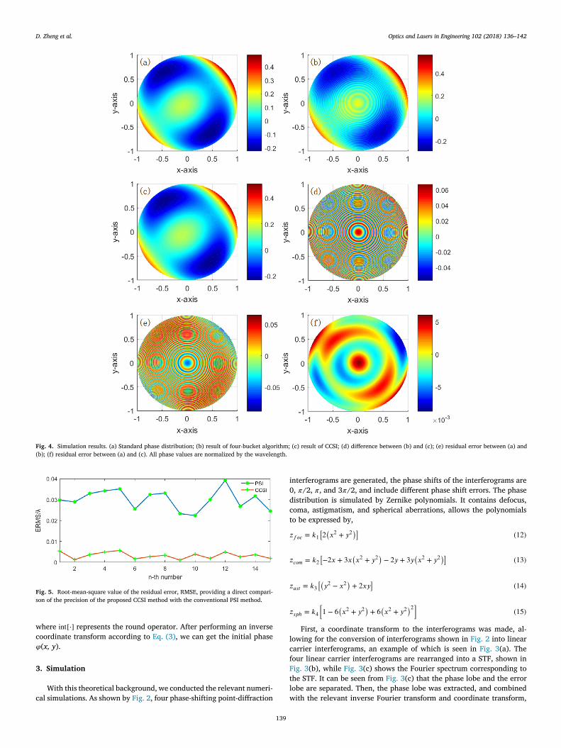
Fig. 4. Simulation results. (a) Standard phase distribution; (b) result of four-bucket algorithm; (c) result of CCSI; (d) difference between (b) and (c); (e) residual error between (a) and
(b); (f) residual error between (a) and (c). All phase values are normalized by the wavelength.
Fig. 5. Root-mean-square value of the residual error, RMSE, providing a direct compari-
son of the precision of the proposed CCSI method with the conventional PSI method.
w
c
𝜑
3
c
i
0
d
c
t
𝑧
𝑧
𝑧
𝑧
l
c
f
F
t
l
w
here int [ ⋅] represents the round operator. After performing an inverse
oordinate transform according to Eq. (3) , we can get the initial phase
( x, y ).
. Simulation
With this theoretical background, we conducted the relevant numeri-
al simulations. As shown by Fig. 2 , four phase-shifting point-diffraction
139
nterferograms are generated, the phase shifts of the interferograms are
, 𝜋/2, 𝜋, and 3 𝜋/2, and include different phase shift errors. The phase
istribution is simulated by Zernike polynomials. It contains defocus,
oma, astigmatism, and spherical aberrations, allows the polynomials
o be expressed by,
𝑓𝑜𝑐 = 𝑘 1 [2 (𝑥 2 + 𝑦 2
)](12)
𝑐𝑜𝑚 = 𝑘 2 [−2 𝑥 + 3 𝑥
(𝑥 2 + 𝑦 2
)− 2 𝑦 + 3 𝑦
(𝑥 2 + 𝑦 2
)](13)
𝑎𝑠𝑡 = 𝑘 3 [(𝑦 2 − 𝑥 2
)+ 2 𝑥𝑦
](14)
𝑠𝑝ℎ = 𝑘 4
[1 − 6
(𝑥 2 + 𝑦 2
)+ 6
(𝑥 2 + 𝑦 2
)2 ](15)
First, a coordinate transform to the interferograms was made, al-
owing for the conversion of interferograms shown in Fig. 2 into linear
arrier interferograms, an example of which is seen in Fig. 3 (a). The
our linear carrier interferograms are rearranged into a STF, shown in
ig. 3 (b), while Fig. 3 (c) shows the Fourier spectrum corresponding to
he STF. It can be seen from Fig. 3 (c) that the phase lobe and the error
obe are separated. Then, the phase lobe was extracted, and combined
ith the relevant inverse Fourier transform and coordinate transform,

D. Zheng et al. Optics and Lasers in Engineering 102 (2018) 136–142
Fig. 6. Circular carrier interferograms.
Fig. 7. Experimental results. (a) Measurement result by SID-4; (b) the retrieved phase by PSI; (c) the retrieved phase by CCSI; (d) difference between (b) and (c); (e) PSI residual error:
residual error between (b) and (a); (f) CCSI residual error: residual error between (c) and (a). All phase values are normalized by the wavelength.
a
t
s
a
d
t
g
p
a
llowing the initial phase under test to be demodulated, Fig. 4 shows
he various simulation results, as well as a comparison of the different
imulation methods used.
In Fig. 4 , the traditional phase-shifting interferometry (PSI) is
dopted for comparison purposes. Fig. 4 (a) shows the standard phase
140
istribution. Fig. 4 (b) and (c) give results using PSI and CCSI, respec-
ively. Fig. 4 (d) shows the difference between the PSI and CCSI, Fig. 4 (e)
ives the residual error distribution between the PSI and the standard
hase, and Fig. 4. (f) is the residual error distribution between the CCSI
nd the standard phase.Their peak-to valley (PV) and root-mean-square

D. Zheng et al. Optics and Lasers in Engineering 102 (2018) 136–142
Fig. 8. Intensity distortion analysis. (a) One of the inteferograms; (b) the retrieved phase by PSI; (c) the retrieved phase by CCSI; (d) difference between (b) and (c).
Fig. 9. Retrieved phase error related to the contrast of the interferograms.
(
t
p
c
g
C
l
d
t
C
T
i
4
w
a
w
m
t
r
B
t
w
r
t
e
m
r
t
F
m
F
r
T
5
5
t
p
p
r
a
C
b
a
RMS) values are shown in Table. 1 . From Fig. 4 (b) to (f), it is obvious
hat, in the phase distribution result using the PSI method, there is a rip-
le error whose spatial frequency is twice as the fringe frequency of the
ircular carrier interferograms. Comparitively, the ripple error which is
enerated by the phase shift error is suppressed well by the proposed
CSI method.
To verify the stability of the proposed CCSI, we repeat the simu-
ations with different phase shift errors (in each simulation, we intro-
uce four different phase shift errors in the four interferograms, respec-
ively.), and use the RMS value of the residual error between the result of
CSI and the standard phase (RMSE) to evaluate the precision of CCSI.
he results are shown in Fig. 5 , compared with PSI, the precision of CCSI
s much better, and the effect of error suppression is obvious.
. Experiments
An experimental device was set up to measure the transmission
avefront of a collimating lens, with a focal length of 550 mm, and
n aperture of 55 mm. The PPDP, which acts as the key component,
as manufactured based on a wire grid polarizer using laser ablation,
ade a pinhole on the metallic wire layer. The retarder array is glued
141
ogether with four retarders whose retardations are 0, 𝜋/2, 𝜋, and 3 𝜋/2,
espectively, with their fast-axes are all along the horizontal direction.
y introducing a defocus along the optical axis, four circular carrier in-
erferograms were captured, as shown in Fig. 6 .
By making the relation analysis to the circular carrier interferograms,
e get the corresponding results in Fig. 7 . Fig. 7 (a) is an experimental
esult which was measured using the SID-4 wavefront sensor manufac-
ured by Phasics corporation in France, which can be viewed as a ref-
rence. Fig. 7 (b) and (c) are the retrieved phase using PSI and CCSI
ethod, respectively, and Fig. 7 (d) shows the difference between the
esults of PSI and CCSI. To make a further comparison, we analyzed
he residuals of the two methods compared to the reference shown in
ig. 7 (a), with Fig. 7 (e) giving the residual phase distribution of the PSI
ethod, while Fig. 7 (f) shows that for the proposed CCSI method. From
ig. 7 (b)–(f), we can see that the ripple phase error that appears in the
esults of the PSI method is strongly suppressed by the CCSI method.
able. 2 shows the PV and RMS values of the results in Fig. 7 .
. Discussion
.1. Intensity distortion
Considering the light intensity consistency error of the four diffrac-
ion orders generated by the grating, we simulated four simultaneous
hase shifting interferograms with different intensity, to verify the sup-
ression ability of CCSI for the intensity distortion error. The simulation
esults are shown in Fig. 8 . Fig. 8 (a) shows one of the interferograms,
nd Fig. 8 (b) and (c) are the phases retrieved by the PSI method, and the
CSI method, respectively, their difference is shown in Fig. 8 (d). It can
e seen that the phase error has a same spatial frequency as the fringes,
nd suppressed by the CCSI method well.
D. Zheng et al. Optics and Lasers in Engineering 102 (2018) 136–142
5
e
t
e
c
𝐻
w
t
s
s
𝑓
i
w
u
d
t
6
(
g
t
r
i
d
i
a
C
r
A
o
J
a
R
[
[
[
[
[
[
[
[
[
[
[
[
[
[
[
[
[
.2. The circular carrier requirement
To ensure the phase lobe is extracted without being affected by the
rror lobe, the carrier should provide separation of the lobes in the spec-
rum of STF. Assume that, the half linewidth of the phase lobe and the
rror lobe are H and H ′ , respectively. Combining Eqs. (8) and (9) , we
an get,
′ =
𝑅 2 1 + 𝑅 1
𝐻 (16)
here 𝑅 2 =
∑𝑁−1 𝑛 =0
𝜀 𝑄𝑛 exp ( − 𝑖 4 𝜋𝑛 𝑓 0 ) 𝑖𝑁
, 𝑅 1 = −
∑𝑁−1 𝑛 =0
𝜀 𝑄𝑛
𝑖𝑁 . Notice that the dis-
ance between the two lobes expressed by Eqs. (8) and (9) is 2 f c , so to
eparate the two lobes expressed by Eqs. (8) and (9) , the circular carrier
hould satisfy,
𝑐 ≥
𝐻
′ + 𝐻
2 =
(
1 +
𝑅 2 1 + 𝑅 1
)
𝐻
2 (17)
At the sametime, we should take the contrast of the interferograms
nto consideration, since the intensity of the diffraction beam decreases
ith the defocus, i.e. the circular carrier f c . We performed some sim-
lations, and the RMSE value is used to evaluate the precision under
ifferent contrasts, with the results shown as Fig. 9 . It can be seen that
he contrast decrease will not result in considerable errors.
. Conclusion
In this paper, we present a circular carrier squeezing interferometry
CCSI). By introducing a defocus, a group of circular carrier interfero-
rams is obtained, and combined with the coordinate transform and STF
echniques, the phase under test can be retrieved and the phase shift er-
or is suppressed effectively. The proposed CCSI method has two follow-
ng advantages. Firstly, it is particularly suitable for phase-shifting point-
iffraction interferometers, also the occasions when measuring a spec-
men with large spherical departure or an on-axis asphere with small
spherical departure. Secondly, there is no retrace error compared to
SI, which requires a linear carrier, usually by tilting the reference mir-
or, and lead to deviation between reflected light and incident light.
cknowledgments
We would like to thank the National Natural Science Foundation
f China (No. 61409052 , 61505082 ). Natural Science Foundation of
iangsu Province (No. BK20160154 ). National Key Scientific Instrument
nd Equipment Development Project ( 2013YQ150829 ).
eferences
[1] Smartt RN , Strong J . Point-diffraction interferometer. J Opt Soc Am.
1972;62:726–35 .
142
[2] Malacara D . Optical shop testing. 3rd ed. Wiley; 2007 .
[3] Park R , Kim DW , Barret HH . Synthetic phase-shifting for optical testing: point-d-
iffraction interferometry without null optics or phase shifters. Opt Express
2013;21(22):26398–417 .
[4] Notaras J , Paterson C . Point-diffraction interferometer for atmospheric adaptive op-
tics in strong scintillation. Opt Commun 2008;281:360–7 .
[5] Paterson C , Notaras J . Demonstration of closed-loop adaptive optics with a point-d-
iffraction interferometer in strong scintillation with optical vortices. Opt Express
2007;15:13745–56 .
[6] Gao P , Yao B , Min J , Guo R , Zheng J , Ye T , et al. Parallel two-step phase-shifting
point-diffraction interferometry for microscopy based on a pair of cube beamsplit-
ters. Opt Express 2011;19(3):1930–5 .
[7] Gao P , Harder I , Nercissian V , Mantel K , Yao B . Phase-shifting point-diffraction in-
terferometry with common-path and in-line configuration for microscopy. Opt Lett
2010;35(5):712–14 .
[8] Kadono H , Nobukatsu T , Asakura T . New common-path phase shifting interferometer
using a polarization technique. Appl Opt 1987;26:898–904 .
[9] Kadono H , Ogusu M , Toyooka S . Phase shifting common path interferometer using
a liquid-crystal phase modulator. Opt Commun 1994;110:391–400 .
10] Guardalben MJ , Ning L , Jian N , Battaglia DJ , Marshall KL . Experimental compar-
ison of a liguid-crystal point-diffraction interferometer(LCPDI) and a commercial
phase-shifting interferometer and methods to improve LCPDI accuracy. Appl Opt
2002;41(7):1353–65 .
11] Neal RM , Wyant JC . Polarization phase-shifting point-diffraction interferometer.
Appl Opt 2006;45(15):3463–76 .
12] de Groot PJ . Vibration in phase-shifting interferometry. J Opt Soc Am
1995;12(2):354–65 .
13] Kwon OY . Multichannel phase-shifted interferometer. Opt Lett 1984;9(2):59–61 .
14] Millerd JE , Martinek SJ , Brock NJ , Hayes JB , Wyant JC . Instantaneous phase-shift
point-diffraction interferometer. Proc SPIE 2004;5380:422–9 .
15] Zheng D , Li J , Chen L , Zhu W , Han Z , Wulan T , et al. Spatial phase-shifting polar-
ization phase-shifting point-piffraction interferometer for wavefront measurement.
Acta Phys Sin 2016;65(11):114203 in Chinese .
16] Guardalben MJ , Jian N . Phase-shift error as a result of molecular align-
ment distortions in a liquid-crystal point-diffraction interferometer. Opt Lett
2011;25(16):1171–3 .
17] Liu Q , Wang Y , Ji F , He J . A three-step least-squares iterative method for tilt
phase-shift interferometry. Opt Express 2013;21(24):29505–15 .
18] Chen Y , Lin P , Lee C , Liang C . Iterative phase-shifting algorithm immune to random
phase shifts and tilts. Appl Opt 2013;52(14):3381–6 .
19] Li J , Zhu R , Chen L , He Y . Phase-tilting interferometry for optical testing. Opt Lett
2013;38(15):2838–41 .
20] Lai G , Yatagai T . Generalized phase-shifting interferometry. J Opt Soc Am A
1991;8(5):822–7 .
21] Patil A , Rastogi P . Approaches in generalized phase shifting interferometry. Opt Las
Eng 2005;43:475–90 .
22] Meneses-Fabian C . Self-calibrating generalized phase-shifting interferometry of
three phase-steps based on geometric concept of volume enclosed by a surface. J
Opt 2016;18:125703 .
23] Yatabe K , Ishikawa K , Oikawa Y . Simple, flexible, and accurate phase re-
trieval method for generalized phase-shifting interferometry. J Opt Soc Am A
2017;34(1):87–96 .
24] Servin M , Cywiak M , Malacara-Hernandez D , Estrada JC , Quiroga JA . “Spatial car-
rier interferometry from M temporal phase shifted interferograms: squeezing inter-
ferometry. Opt Express 2008;16(13):9276–83 .
25] Li B , Chen L , Wulan T , Ma S , Zhu R . Carrier squeezing interferometry: suppressing
phase errors from the inaccurate phase shift. Opt Lett 2011;36(6):996–8 .
26] Zhu RG , Li B , Zhu RH , He Y , Li J . Phase extraction from two phase-shifting fringe
patterns using spatial-temporal fringes method. Opt Express 2016;24(7):6814–24 .