operations manual - dustbane.ca · operations manual gladiator 1050 ride-on gladiator series code:...
TRANSCRIPT
Operations Manual
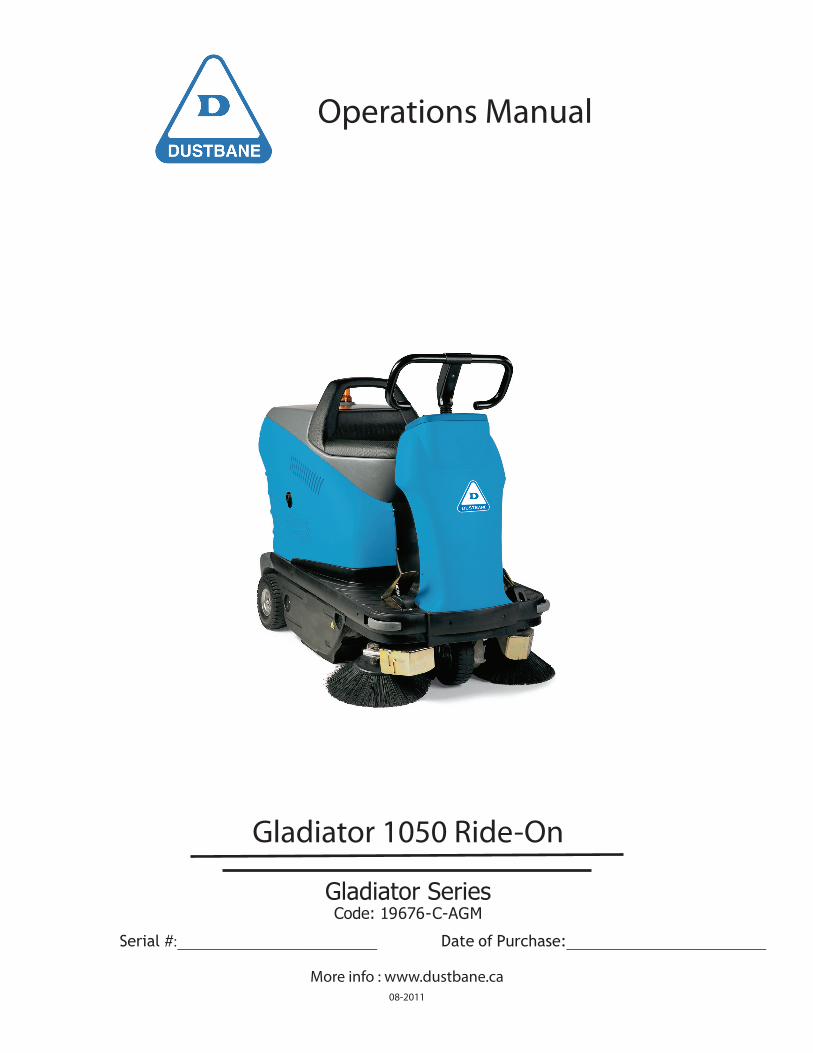
Gladiator 1050 Ride-On
Gladiator SeriesCode: 19676-C-AGM
Serial #:_________________________ Date of Purchase:_________________________
More info : www.dustbane.ca08-2011
1. Index
1. Index 22. Introduction / General Warnings 23. Introduction 24. General Safety Rules 25. Modifications And Improvements 36. Safety 37. Unpacking 38. The Controls and the Control Panel 49. Preparing The Machine 510. Removing the Batteries 611. Turning on the Machine 612. Auto-Power-On/Off 713. Using the Work Programmes 714. Emptying the Waste Bin 815. Cleaning and Servicing the Filter 916. Fitting and Replacing the Side Brushes 917. Replacing Light Bulbs 918. Replacing the Centre Brush 1019. Adjusting the Brake 1220. Summary Table 13 20.1 Maintenance 13 20.2 Troubleshooting Table 14 20.3 Drive board alarms 15
2
2. Introduction / General Warnings
Welcome on board!
We thank you for choosing Dustbane and congratulate you for purchasing the 1050 A sweeper especially designed to guarantee safety and concern for the environment. The innovative design, the robust and trustworthy structure and the recyclable components make a 1050 sweeper. A truly unique machine. Before using your machine, we advise you to carefully read this handbook. It is an invaluable guide to the characteristics of your machine and will help you use it correctly.
In particular, it provides precious information concerning safety, integrity and concern for the environment.
3. Introduction
This instruction handbook contains guidelines and practical information concerning the use, adjustment and routine maintenance of your new machine. Your machine has been designed and built to offer the best in terms of performance, comfort and ease-of-use in a variety of different conditions. Before delivery, your machine has been checked at our factory and by our dealer to guarantee that it is handed over to you in perfect working order. To maintain the machine in this condition and ensure problem-free operation, strictly follow the instructions given in the handbook. Before attempting to use the machine, read this handbook and keep it to hand for any future consultation. The words RIGHT and LEFT always refers to the direction in which the machine is travelling. If you have any doubts concerning the machine, do not hesitate to contact your dealer. Dealers will offer you competent personnel, original spare parts and all the equipment you will need. NEVER use the machine without its guards and safety systems. For your safety, make sure all guards and safety systems are closed and correctly mounted before starting the machine.
4. General Safety Rules
To prevent damage and bodily harm, strictly follow the safety rules below.
Read the safety labels on the machine and do not cover them for any reason whatsoever. Replace them if they are damaged or become unreadable.
• The storage temperature ranges from 0° to + 50°C.• The optimal working temperature should range from 0° and + 40°C.• The ambient humidity must range from 30 to 95 %.• Do not use the machine as means of transport.• Do not use solvents or similar substances to clean the machine.• Avoid running the brushes when the machine is still, to prevent damage the floor.• Do not use the machine to draw up inflammable liquid.• If fires break out, use a dry-chemical extinguisher. DO NOT USE WATER.• Do not bump against shelves or scaffolding when there is a risk of objects falling over.• Adapt the speed of the machine to the conditions of adherence.• Avoid using the machine if its stability is not guaranteed.• If you notice that the machine is not working properly, make sure this does not depend on failure
to carry out the routine maintenance operations. If this is not your case, contact an authorized service center.
• Always use ORIGINAL spare parts. You can purchase these from a dealer or authorized retailer.
3
• Disconnect the machine from the mains before carrying out any maintenance operation.• Do not remove guards that need to be removed with the aid of tools.• Do not wash the machine with direct jets of pressurized water or with corrosive substances.• Every 200 hours of work, have the machine checked by an authorized service center.
Special waste. Do not dispose of with ordinary waste
Use and storage in environments where there is a risk of explosion is prohibited.
5. Modifications And Improvements
Our company policy is based on the continuous improvement of our products. We therefore reserve the right to apply modifications and improvements whenever we believe these are necessary, without having to upgrade the machines previously sold.
6. Safety
Accident-prevention is also your responsibility.
No accident-prevention plan can be effective without the total cooperation of the person directly responsible for machine operation. Most accidents that occur in a company, during work or transport are caused by failure to observe the basic rules concerning safety.
A careful and prudent user is the best guarantee against accidents and will prove to be much more effective than even the strictest accident-prevention plan. During work, pay attention to the persons standing in the area to clean, especially children.
7. Unpacking
Unpack your machine with great care, avoiding any maneuver that could lead to damage.
Once you have unpacked it, make sure all parts are in a good condition. If you notice any damage, DO NOT use the machine and contact your retailer immediately.
For reasons concerning packaging and transport, some parts and optional items may be supplied disassembled. To assemble them, follow the instructions given in this handbook in the respective sections.
If you notice that any of the above are missing, contact your retailer immediately.
NOTE To prevent it from getting lost during transport, the keys have been put inside the envelope containing the technical literature.
Make sure the packaging materials (bags – cartons – pallets – hooks – etc.) are put away, out of the reach of children.
4
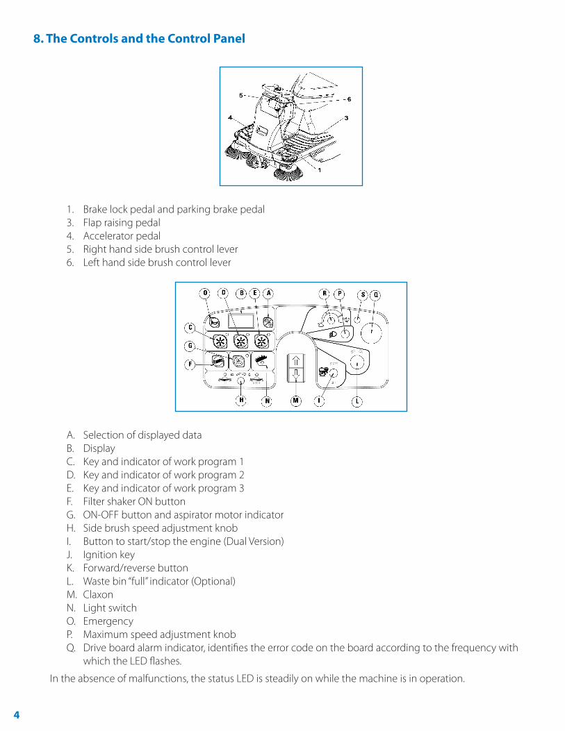
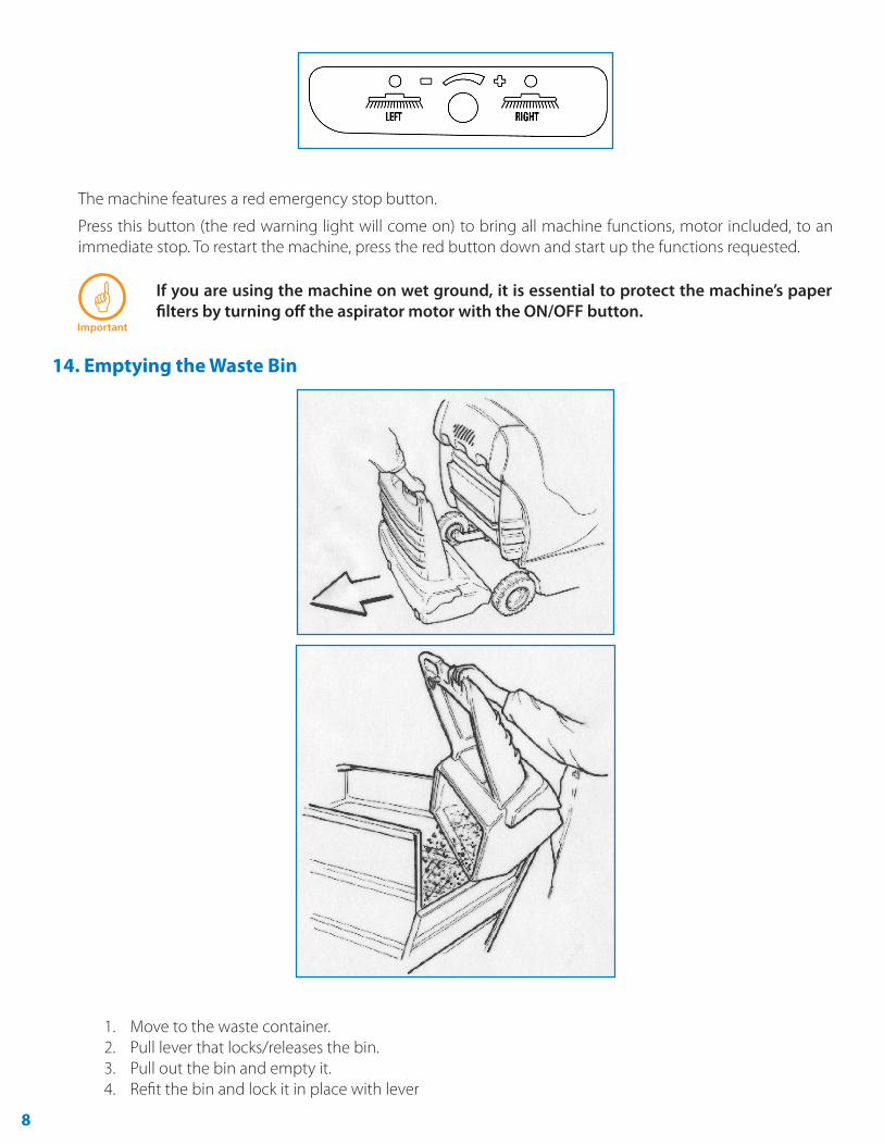
8. The Controls and the Control Panel
1. Brake lock pedal and parking brake pedal3. Flap raising pedal4. Accelerator pedal5. Right hand side brush control lever6. Left hand side brush control lever
A. Selection of displayed dataB. DisplayC. Key and indicator of work program 1D. Key and indicator of work program 2E. Key and indicator of work program 3F. Filter shaker ON buttonG. ON-OFF button and aspirator motor indicatorH. Side brush speed adjustment knobI. Button to start/stop the engine (Dual Version)J. Ignition keyK. Forward/reverse buttonL. Waste bin “full” indicator (Optional)M. ClaxonN. Light switchO. EmergencyP. Maximum speed adjustment knobQ. Drive board alarm indicator, identifies the error code on the board according to the frequency with
which the LED flashes.
In the absence of malfunctions, the status LED is steadily on while the machine is in operation.
5
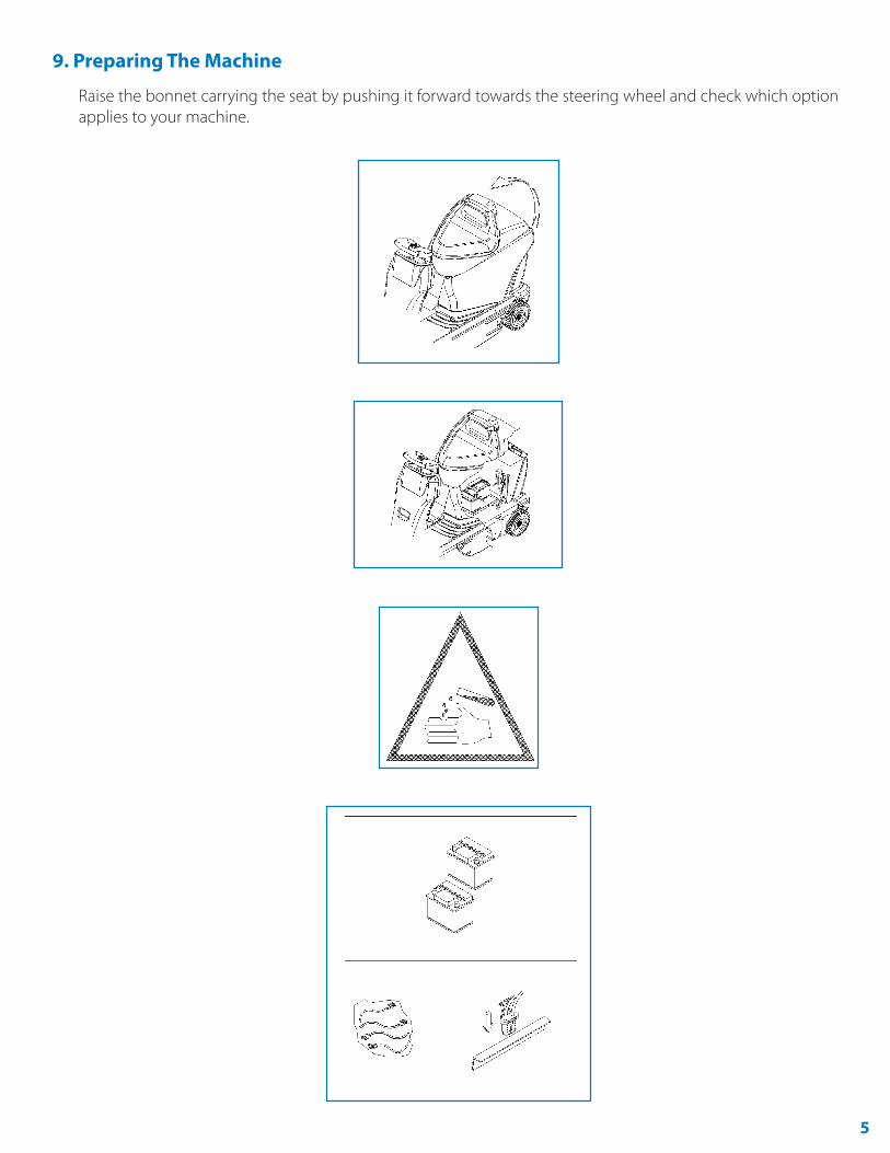
9. Preparing The Machine
Raise the bonnet carrying the seat by pushing it forward towards the steering wheel and check which option applies to your machine.
6
The electrical connection cables supplied with the machine may be used to connect the batteries. Once the batteries have been installed, connect the battery connector to the machine.
10. Removing the Batteries
When removing the batteries, the operator must be equipped with suitable personal protection devices (gloves, goggles, overalls, safety shoes, etc) to reduce the risk of accidents.
Make sure the switches on the control panel are in the “0” position (off ) and the machine is turned off. Keep away from naked flames, do not short circuit the battery poles, do not cause sparks and do not smoke. Proceed as follows.
1. Disconnect the battery wiring and bridge terminals from the battery poles.2. If necessary, remove the devices fixing the battery to the base of the machine.3. Lift the batteries from the compartment using suitable lifting equipment.
11. Turning on the Machine
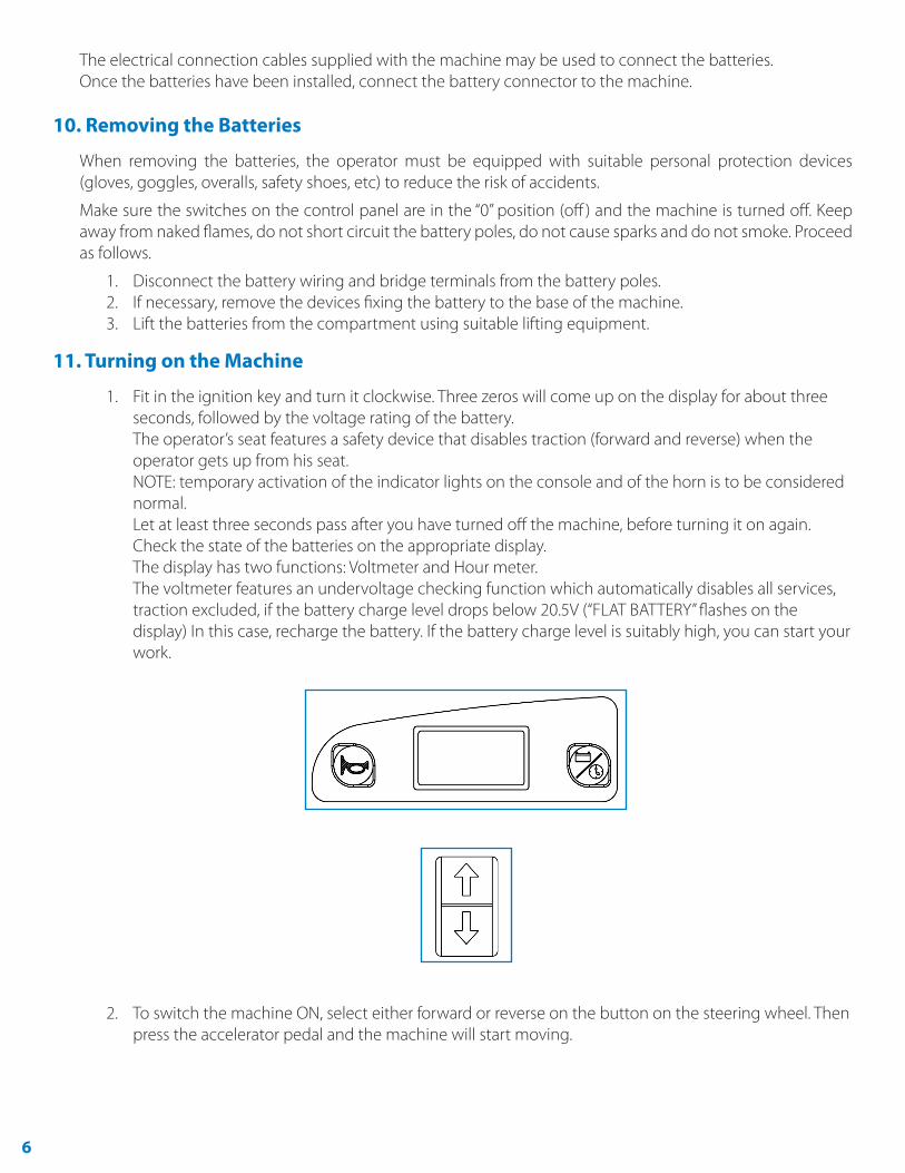
1. Fit in the ignition key and turn it clockwise. Three zeros will come up on the display for about three seconds, followed by the voltage rating of the battery. The operator’s seat features a safety device that disables traction (forward and reverse) when the operator gets up from his seat. NOTE: temporary activation of the indicator lights on the console and of the horn is to be considered normal. Let at least three seconds pass after you have turned off the machine, before turning it on again. Check the state of the batteries on the appropriate display. The display has two functions: Voltmeter and Hour meter. The voltmeter features an undervoltage checking function which automatically disables all services, traction excluded, if the battery charge level drops below 20.5V (“FLAT BATTERY” flashes on the display) In this case, recharge the battery. If the battery charge level is suitably high, you can start your work.
2. To switch the machine ON, select either forward or reverse on the button on the steering wheel. Then press the accelerator pedal and the machine will start moving.
7
12. Auto-Power-On/Off
An automatic system turns the machine functions on and off automatically.
When one of the three work programs is selected by pressing the P1, P2 or P3 button, the following functions are temporarily activated: center brush, suction motor, side brushes. The LED of the chosen program and the center brush LED come on at the same time. If the accelerator pedal is not pressed, after a few seconds the functions shut down and the three LEDS start flashing. The sweeper is now in AUTOPOWER- OFF mode. All functions are automatically reactivated when the user presses the accelerator pedal: AUTO-POWER-ON.
NOTE: When the accelerator is released all the machine functions are automatically switched off.
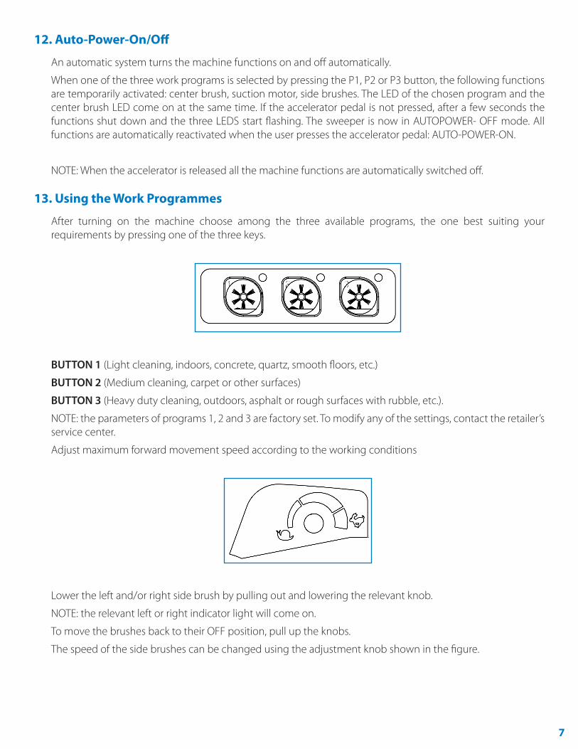
13. Using the Work Programmes
After turning on the machine choose among the three available programs, the one best suiting your requirements by pressing one of the three keys.
BUTTON 1 (Light cleaning, indoors, concrete, quartz, smooth floors, etc.)
BUTTON 2 (Medium cleaning, carpet or other surfaces)
BUTTON 3 (Heavy duty cleaning, outdoors, asphalt or rough surfaces with rubble, etc.).
NOTE: the parameters of programs 1, 2 and 3 are factory set. To modify any of the settings, contact the retailer’s service center.
Adjust maximum forward movement speed according to the working conditions
Lower the left and/or right side brush by pulling out and lowering the relevant knob.
NOTE: the relevant left or right indicator light will come on.
To move the brushes back to their OFF position, pull up the knobs.
The speed of the side brushes can be changed using the adjustment knob shown in the figure.
8
The machine features a red emergency stop button.
Press this button (the red warning light will come on) to bring all machine functions, motor included, to an immediate stop. To restart the machine, press the red button down and start up the functions requested.
Important
If you are using the machine on wet ground, it is essential to protect the machine’s paper filters by turning off the aspirator motor with the ON/OFF button.
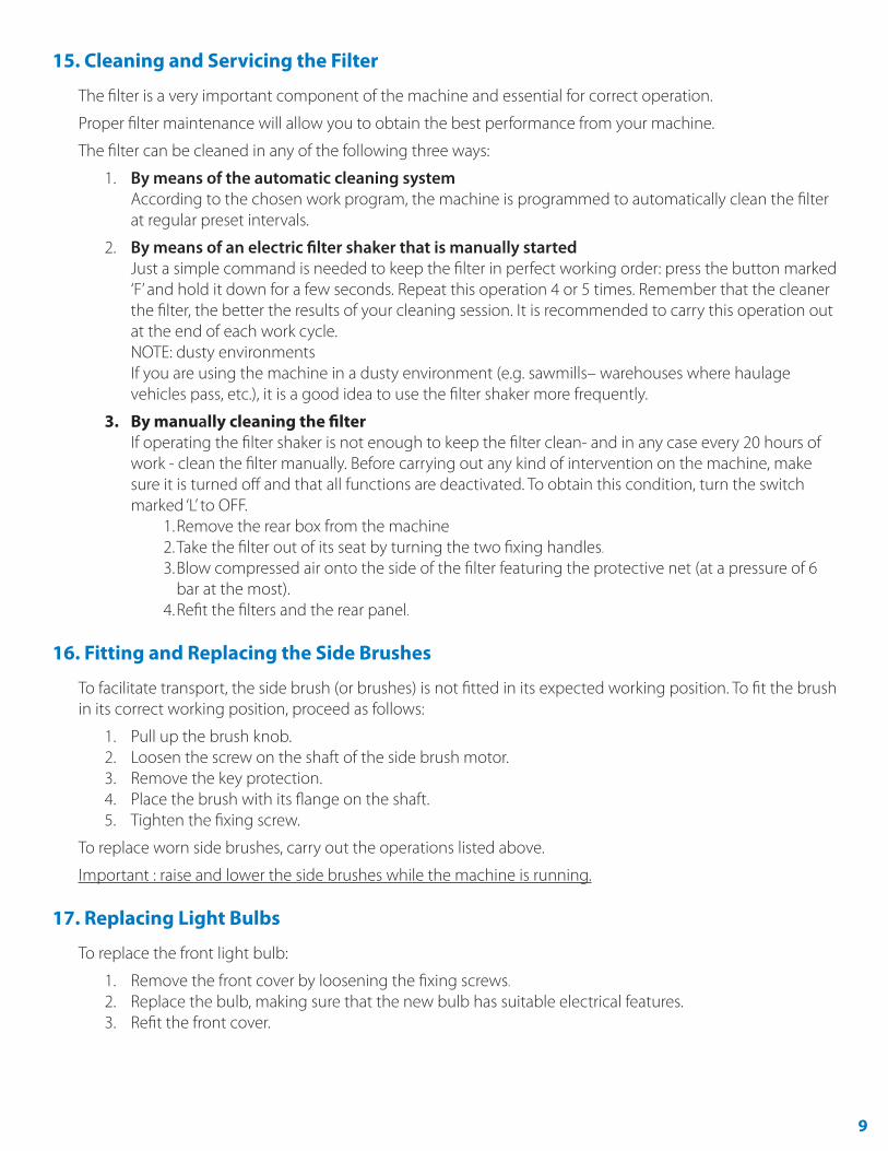
14. Emptying the Waste Bin
1. Move to the waste container.2. Pull lever that locks/releases the bin.3. Pull out the bin and empty it.4. Refit the bin and lock it in place with lever
9
15. Cleaning and Servicing the Filter
The filter is a very important component of the machine and essential for correct operation.
Proper filter maintenance will allow you to obtain the best performance from your machine.
The filter can be cleaned in any of the following three ways:
1. By means of the automatic cleaning system According to the chosen work program, the machine is programmed to automatically clean the filter at regular preset intervals.
2. By means of an electric filter shaker that is manually started Just a simple command is needed to keep the filter in perfect working order: press the button marked ‘F’ and hold it down for a few seconds. Repeat this operation 4 or 5 times. Remember that the cleaner the filter, the better the results of your cleaning session. It is recommended to carry this operation out at the end of each work cycle. NOTE: dusty environments If you are using the machine in a dusty environment (e.g. sawmills– warehouses where haulage vehicles pass, etc.), it is a good idea to use the filter shaker more frequently.
3. By manually cleaning the filter If operating the filter shaker is not enough to keep the filter clean- and in any case every 20 hours of work - clean the filter manually. Before carrying out any kind of intervention on the machine, make sure it is turned off and that all functions are deactivated. To obtain this condition, turn the switch marked ‘L’ to OFF.
1. Remove the rear box from the machine2. Take the filter out of its seat by turning the two fixing handles.
3. Blow compressed air onto the side of the filter featuring the protective net (at a pressure of 6 bar at the most).
4. Refit the filters and the rear panel.
16. Fitting and Replacing the Side Brushes
To facilitate transport, the side brush (or brushes) is not fitted in its expected working position. To fit the brush in its correct working position, proceed as follows:
1. Pull up the brush knob.2. Loosen the screw on the shaft of the side brush motor.3. Remove the key protection.4. Place the brush with its flange on the shaft.5. Tighten the fixing screw.
To replace worn side brushes, carry out the operations listed above.
Important : raise and lower the side brushes while the machine is running.
17. Replacing Light Bulbs
To replace the front light bulb:
1. Remove the front cover by loosening the fixing screws.
2. Replace the bulb, making sure that the new bulb has suitable electrical features.3. Refit the front cover.
10
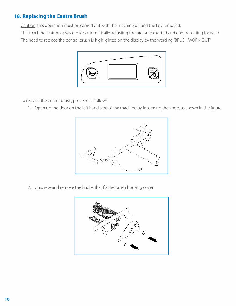
18. Replacing the Centre Brush
Caution: this operation must be carried out with the machine off and the key removed.
This machine features a system for automatically adjusting the pressure exerted and compensating for wear.
The need to replace the central brush is highlighted on the display by the wording “BRUSH WORN OUT”
To replace the center brush, proceed as follows:
1. Open up the door on the left hand side of the machine by loosening the knob, as shown in the figure.
2. Unscrew and remove the knobs that fix the brush housing cover
11
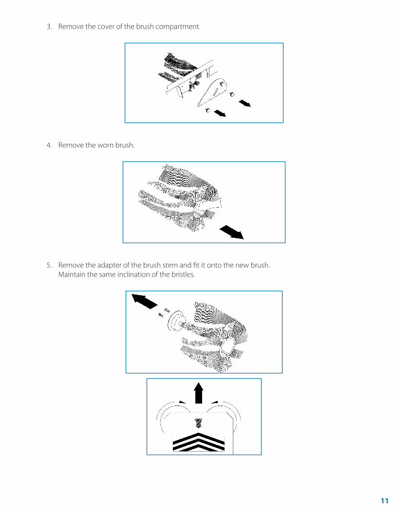
3. Remove the cover of the brush compartment.
4. Remove the worn brush.
5. Remove the adapter of the brush stem and fit it onto the new brush. Maintain the same inclination of the bristles.

12
6. Refit the adapter and mount the new brush. Make sure the adapter is inserted into the hub.
7. Refit the cover of the brush compartment and tighten the knobs by following the disassembly instructions in reverse order.
19. Adjusting the Brake
If the service brake or parking brake is not effective enough, it can be adjusted by acting on the front wheel. Loosen locknut B by turning screw A and then tighten locknut B again.
13
20. Summary Table
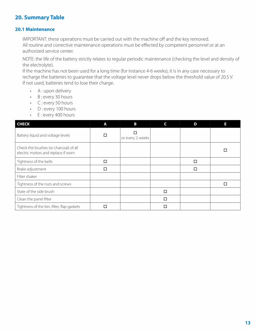
20.1 Maintenance
IMPORTANT: these operations must be carried out with the machine off and the key removed. All routine and corrective maintenance operations must be effected by competent personnel or at an authorized service center.
NOTE: the life of the battery strictly relates to regular periodic maintenance (checking the level and density of the electrolyte). If the machine has not been used for a long time (for instance 4-6 weeks), it is in any case necessary to recharge the batteries to guarantee that the voltage level never drops below the threshold value of 20.5 V. If not used, batteries tend to lose their charge.
• A : upon delivery• B : every 30 hours• C : every 50 hours• D : every 100 hours• E : every 400 hours
CHECK A B C D E
Battery liquid and voltage levels
or every 2 weeks
Check the brushes (or charcoal) of all electric motors and replace if worn
Tightness of the belts
Brake adjustment
Filter shaker
Tightness of the nuts and screws
State of the side brush
Clean the panel filter
Tightness of the bin, filter, flap gaskets
14
20.2 Troubleshooting Table
SECURITY CODE MACHINE BEHAVIOUR ERROR DESCRIPTION POSSIBLE INTERVENTION
Traction Pause The traction is blocked. The electronic control circuit overheats to > 85°c.
If the atmospheric temperature is high, stop the machine for 20 minutes and then restart it. if the problem persists, call the service centre.
Brush Current The operating functions stop. Excessive power draw or central brush lock.
Check the brush runs smoothly and check for any impediments (string, nylon or other).
Battery Reserve Warning that the battery is almost flat.
This happens when the battery voltage falls below 21v.
No intervention required other than charging the battery.
Flat Battery The machine functions all stop with the exception of the traction.
If for 3 consecutive seconds the voltage read by the key is less than 20, 3v.
Recharge the battery.
Battery Worn Out The machine is blocked. If for 3 consecutive seconds the voltage read by the key is less than 18v.
Recharge the battery.
Brush Worn Out The machine continues to run. The brush no longer applies suitable pressure to the floor as it is worn out.
Replace the central brush.
15
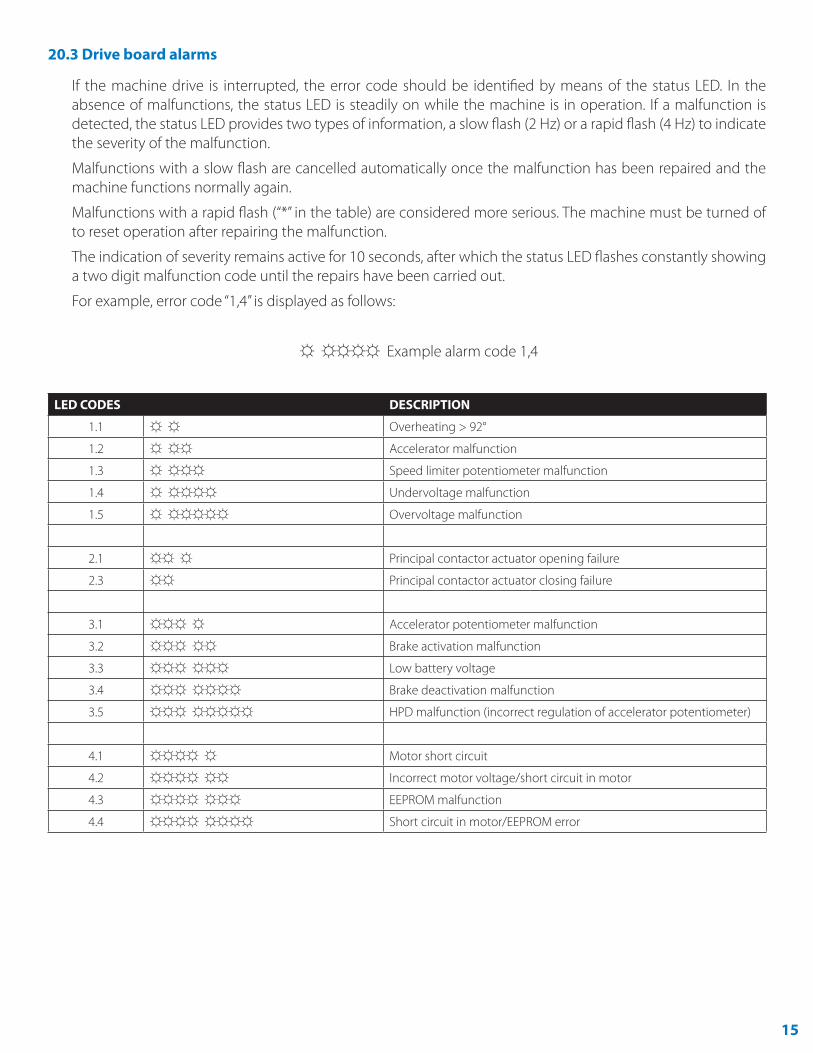
20.3 Drive board alarms
If the machine drive is interrupted, the error code should be identified by means of the status LED. In the absence of malfunctions, the status LED is steadily on while the machine is in operation. If a malfunction is detected, the status LED provides two types of information, a slow flash (2 Hz) or a rapid flash (4 Hz) to indicate the severity of the malfunction.
Malfunctions with a slow flash are cancelled automatically once the malfunction has been repaired and the machine functions normally again.
Malfunctions with a rapid flash (“*” in the table) are considered more serious. The machine must be turned of to reset operation after repairing the malfunction.
The indication of severity remains active for 10 seconds, after which the status LED flashes constantly showing a two digit malfunction code until the repairs have been carried out.
For example, error code “1,4” is displayed as follows:
☼ ☼☼☼☼ Example alarm code 1,4
LED CODES DESCRIPTION
1.1 ☼ ☼ Overheating > 92°
1.2 ☼ ☼☼ Accelerator malfunction
1.3 ☼ ☼☼☼ Speed limiter potentiometer malfunction
1.4 ☼ ☼☼☼☼ Undervoltage malfunction
1.5 ☼ ☼☼☼☼☼ Overvoltage malfunction
2.1 ☼☼ ☼ Principal contactor actuator opening failure
2.3 ☼☼ Principal contactor actuator closing failure
3.1 ☼☼☼ ☼ Accelerator potentiometer malfunction
3.2 ☼☼☼ ☼☼ Brake activation malfunction
3.3 ☼☼☼ ☼☼☼ Low battery voltage
3.4 ☼☼☼ ☼☼☼☼ Brake deactivation malfunction
3.5 ☼☼☼ ☼☼☼☼☼ HPD malfunction (incorrect regulation of accelerator potentiometer)
4.1 ☼☼☼☼ ☼ Motor short circuit
4.2 ☼☼☼☼ ☼☼ Incorrect motor voltage/short circuit in motor
4.3 ☼☼☼☼ ☼☼☼ EEPROM malfunction
4.4 ☼☼☼☼ ☼☼☼☼ Short circuit in motor/EEPROM error