operation/maintenance - caterpillar · pdf fileoperation/maintenance manual ... by the...
TRANSCRIPT

INSERO EQUIPMENT | 11002 SAPP BROTHERS DRIVE | OMAHA, NE 68138INSEROEQUIPMENT.COM | 855.604.2117
H E A T E R
OPERATION/MAINTENANCEAND
PARTS MANUAL
READ INSTRUCTIONS PRIOR TO STARTING HEATERES


INSPECTION CHECK LISTPREPARING THE INSERO HEATER FOR DELIVERY OR RENTAL
The Insero Equipment Heater requires service as well as proper operation in order to provide the performance and safety for which it was designed. Never deliver or put a machine into service with known defects or missing instructions or decals. Always instruct the customer in the proper operation and safety procedures as described in the operator’s manual.
Check List: » Visually inspect the equipment to ensure that all instructions and
decals are in place and legible. » Check the hitch assembly and safety tow chains. » Check the jack to make sure it operates properly. » Inspect the tires to ensure proper inflation and condition. » Check lug nuts and torque to 80-90 ft. lbs. After first 100 miles of towing
lug nuts should be re-torqued. » Check the ground rod cable and the ground lug. Make sure they are
clean, undamaged and functional. » Make sure the battery is fully charged and the terminals are tight and
clean. Ensure the electrolyte is at the correct level. » Check the service intervals for oil filters, fuel filters, air cleaner and
engine oil. » Check the oil, fuel and coolant levels. » To ensure proper operation, start engine and turn heaters on.
SAFETY WARNING!
NEVER ALLOW ANYONE TO OPERATE THE EQUIPMENT WITHOUT PROPER TRAINING.
ALWAYS READ THE MANUAL FIRST.INSERO EQUIPMENT | 11002 SAPP BROTHERS DRIVE | OMAHA, NE 68138
INSEROEQUIPMENT.COM | 855.604.2117


TABLE OF CONTENTSWARRANTY STATEMENTSInsero Heater Warranty, Procedures & Claim Form .......................................................................... 1-3
Marathon Electric Generator Warranty ..................................................................................................4
Cat C1.5 Tier 4 Diesel Engine Warranty ............................................................................................... 5-7
OPERATION/MAINTENANCE MANUALSpecifications ...........................................................................................................................................8
Installation Instructions ...........................................................................................................................9
Operating Instructions ........................................................................................................................... 10
Maintenance Instructions ...................................................................................................................... 11
Cleaning Procedure ................................................................................................................................ 12
Temperature Feeler Adjustment ............................................................................................................ 13
Settings ...............................................................................................................................................14-16
Primary Controls (Honeywell & Genisys Controls) ..........................................................................17-19
Burner Assembly Components .........................................................................................................20-21
Limits, Fan Switches and Temperature Feelers ................................................................................... 22
Heat Exchanger for Oil Units ................................................................................................................. 23
IDF 500 Front View & Back View w. Labels .....................................................................................24-25
HEATER PARTS MANUALHeater Exterior ...................................................................................................................................26-27
Engine Compartment .............................................................................................................................. 28
Battery Components ............................................................................................................................... 29
Control Panel ........................................................................................................................................... 30
Accessories ............................................................................................................................................ 31
Trailer Components ................................................................................................................................. 32
Electrical Components ........................................................................................................................... 33
Accessories ............................................................................................................................................ 34
Burner Fuel System ................................................................................................................................ 35
Placards and Decals .............................................................................................................................. 36
SCHEMATICS/WIRING DOCUMENTSTrailer Harness/Control Panel Wiring Diagram .................................................................................... 37
E-Stop and Air Intake Wiring Diagram .................................................................................................. 38
Engine Harness Wiring Diagram ........................................................................................................... 39
Fan Motor, Honeywell and Genisys Control Wiring Diagram .........................................................40-42
Trailer Schematics .............................................................................................................................43-44
TROUBLE SHOOTINGTrouble Shooting ................................................................................................................................45-46


WARRANTY STATEMENTS


INSERO EQUIPMENT® HEATER LIMITED WARRANTY
Diversified Products, LLC dba Insero Equipment
(hereinafter, “Insero”) warrants its Insero Equipment®
Heater to be free from defects in materials and
workmanship for period of one (1) year or 1,000 hours,
whichever occurs first, from the date of delivery to the
original purchaser.
If a defect in material or workmanship is found during
the warranty period, Insero will, during normal working
hours and through an authorized Insero Equipment
Heater dealer or other source approved by Insero, repair
or replace (at Insero’s option) the defective goods or
parts, without charge to the original purchaser. This
warranty does not renew or extend with repaired or
replaced goods or parts. All warranties are from the date
of delivery of the original product.
This warranty covers the trailer structure from bumper to
bumper. This warranty is not applicable to items which
are individually covered by the component
manufacturers, such as the base engine which is
warranted according to the terms and conditions supplied
by the Caterpillar Engine Division. All warranty
information from such other manufacturers is provided
within or accompany these goods.
This warranty is non-transferrable and applies only to the
original purchaser.
EXCLUSIONS FROM THIS WARRANTY
This warranty does not cover:
Conditions resulting from misuse, natural calamities,
improper storage, negligence, alteration, accident,
unapproved attachments or usage which is contrary to
the intended purpose.
Conditions resulting from the failure to perform routine
maintenance.
Items normally designed to be periodically replaced by
the equipment owner during the equipment life due to
normal wear and tear.
Damage to the finish of the trailer or other appearance
parts caused by wear.
PURCHASER RESPONSIBILITIES
The purchaser is responsible for:
Providing proof of purchase and the date of delivery.
Local taxes, if applicable.
All costs associated with transporting the equipment to
and from the authorized Insero Equipment Heater
dealer or other source approved by Insero.
Premium or overtime labor costs.
Costs to investigate complaints, unless the problem is
caused by a defect in material or workmanship.
Giving timely notice of a warrantable failure and
promptly making the equipment available for repair.
Performance of required maintenance and items
replaced due to normal wear and tear.
Freight on goods and parts returned to factory for
inspection or repair.
SHIPPING Shipping charges are paid under this warranty by Insero
for replacement parts only. Insero will not be held
responsible for delays in shipping. In the event it is
necessary to return goods or parts to Insero for repair or
inspection, purchaser shall be responsible for and must
prepay such shipping expense.
WARRANTY ACTION In order to recover under this warranty, the original
purchaser must submit a claim to Insero or an authorized
Insero Equipment Heater dealer within 30 days of
discovery of the alleged defect. To be covered by this
warranty, service must be performed by an authorized
Insero Equipment Heater dealer or other source approved
by Insero. It is the responsibility of the purchaser to
transport the equipment to the service shop of an
authorized Insero Equipment Heater dealer or other
approved source for service.
EXCLUSIVE REMEDY AND LIMITATION OF
LIABILITY The obligation of Insero under this warranty is limited
solely to repair or replacement of defective goods or
parts. THIS WARRANTY IS EXCLUSIVE AND IN
LIEU OF ALL OTHER WARRANTIES, EXPRESS OR
IMPLIED, ARISING BY LAW OR CUSTOM,
INCLUDING IMPLIED WARRANTIES OF
MERCHANTABILITY AND FITNESS FOR A
PARTICULAR PURPOSE. IN NO EVENT SHALL
DIVERSIFED BE LIABLE FOR SPECIAL, INDIRECT
OR CONSEQUENTIAL DAMAGES INCLUDING
BUT NOT LIMITED TO LOSS PROFITS, OTHER
COMMERCIAL LOSSES, INCONVENIENCE, OR
COST OF RENTAL OR REPLACEMENT
EQUIPMENT. THE LIABILITY OF INSERO UNDER
THIS WARRANTY SHALL IN NO WAY EXCEED
THE PURCHASE PRICE OF THE INSERO
EQUIPMENT HEATER.
Some states or providences do not allow exclusion or
limitation of incidental or consequential damages, or
exclusions or limitations of implied warranties or conditions, so such exclusions or limitations may not
apply.
INSEROEQUIPMENT.COM | 855.604.2117 1

INSERO EQUIPMENT HEATER WARRANTY PROCEDURE
FOR PRODUCTS MANUFACTURED BY INSERO EQUIPMENTAny component, sub-assembly, or device manufactured by Insero Equipment will be warranted as stated in the Insero Equipment Limited Warranty.
As stated by the Insero Equipment Limited Warranty, if a component, sub-assembly or device manufactured by anyone other than Insero should fail, it shall be warranted by its manufacturer, however, in some cases, this will be handled through the Insero Equipment Warranty Department. Therefore, notification must be made to Insero Equipment upon failure for proper warranty procedure.
STANDARD WARRANTY PROCEDURE:1. Upon notice of warrant able failure, information should be gathered specific to the cause and results of the failure. Warranty claim requests must be filed within 30 days of failure.
2. Contact the Insero Equipment Service Part & Service Department and explain the situation, including model and serial number of machine, hours on machine, etc.
3. If replacement of components or sub-assembly is determined necessary, Insero Equipment Service Parts & Service Department will advise as to the proper procedure to either repair or replace as necessary and warranty coverage available. Insero Equipment Service Parts & Service Department will determine if the parts can be supplied for replacement without being returned for inspection. When it is necessary to return parts for inspection, Insero Equipment will issue a Returned Goods Authorization (RGA) Number for the return of the components. All parts to be returned shall be shipped prep aid by customer. Insero Equipment will ship replacement parts via ground freight only and invoice the customer for parts and freight as necessary. Expedited freight specified by customer will be billed to the customer. Upon examination of parts, Insero Equipment will determine warranty coverage and will issue credit for replacement parts and labor based on the criteria listed above. All defective parts must be returned within 30 days for examination for credit to be issued.
4. If field repairs are necessary, contact the Insero Equipment Parts & Service Department for prior authorization or warranty may be voided. Any repairs approved by Insero Equipment will be paid as deemed appropriate by Insero Equipment upon receipt of claim, if filed within 30 days of failure.
INSERO EQUIPMENTCONTACT: AARON JOHNSON11002 SAPP BROTHERS DRIVEOMAHA, NE 68138PHONE: 855.604.2117FAX: 402.891.7565
INSEROEQUIPMENT.COM
INSEROEQUIPMENT.COM | 855.604.2117 2

Rev.
RReettuurrnn ttoo ::
DDaattee:: ______//______//______ CCuussttoommeerr CCllaaiimm NNoo..__________________________
LLAABBOORRHours Rate Description Cost
$$$
Transportation, travel, pick-up, lost revenue, delivery, and freight costs are ABSOLUTELY NOT covered by Warranty.
PPAARRTTSS RRee ttuurrnn PPaarrttss RRGG AA## __________________
Qty. Part Number Description Part # Cost$$$
ALL returnable parts MUST be received and have an RGA number before processing.PPlleeaassee rreettuurrnn ppaarrtt ss wwiitthhiinn 3300 ddaayyss ffoorr pprroommpptt pprroocceessssiinngg ooff wwaarrrraanntt yy ccllaaiimm..
Total labor cost of repair/replacement of parts only: LABOR $
Total cost of part(s) used in repairing unit: PARTS $
Total amount claimed, parts and labor combined: TOTAL $
Filed by: _____________________________ Title: _____________________________
Labor performedby: _________________________________ Contact: _______________________
PPrroodduucctt IInnffoorrmmaattiioonn
Product Name: __________________ Model #: ____________ Serial #: ____________ Hours: _____
Date Purchased:____/____/____ Date Put In Service:____/____/____ Date of Failure:____/____/____
Description of Failure:________________________________________________________________
Cause of Failure (if known):____________________________________________________________
For office use only
Claim is / is not granted. Authorized signature: _____________________ ____ Date: ____/____/____
Comments: ________________________________________________________________________________ _________________________________________________________________________________________
Action Directed: _____________________________________________________________________________
TOTAL CREDIT: $_________________
CCuu ssttoommeerr IInnffoorrmmaattiioonn
Name: __________________________________Address: ________________________________City: ___________________ St: ____ Zip:______Phone: _______________ Fax: ______________E-mail: __________________________________
DDeeaa llee rr//RReepp IInnffoorrmmaattiioonn
Name: ___________________________________Address: _________________________________City: ___________________ St: ____ Zip:_______Phone: _______________ Fax: _______________E-mail: ___________________________________
INSEROEQUIPMENT.COM | 855.604.2117 3

WARRANTIES TO DISTRIBUTORS AND INDUSTRIAL ORCOMMERCIAL CUSTOMERS
This warranty is extended only to Marathon’s distributors and industrial or commercial customers and does not apply to consumer purchasers. This warranty applies to all generator and related parts sales.
WARRANTY PERIOD - (a) Marathon warrants Standby Duty Generators manufactured by or for it to be free from defects in materials and workmanship and to conform to Marathon’s written specifications fora period of 24 months from date of startup, 30 months from date of shipment, or 1000 hours in use, ichever period shall expire first. (b) Marathon warrants the Continuous Duty Generators manufactured by or for it to be free from defects in materials and workmanship and to conform to Marathon’s written specifications for a period of 12 months from date of startup or 18 months from date of shipment, whichever period shall expire first.
WARRANTY REMEDIES - If, prior to expiration of the foregoing applicable warranty period, any of such products shall be proved to Marathon’s satisfaction to be defective or nonconforming, Marathon will repair or replace such defective equipment or components thereof, F.O.B. Marathon’s plant or other destination designated by Marathon, or will refund or provide Buyer with a credit in the amount of the purchase price paid therefor by Buy-er, at Marathon’s sole option. Buyer’s exclusive remedy and Marathon’s sole obligation under this warranty shall be limited to such repair or replacement, F.O.B. Marathon’s plant or other destination designated by Marathon, or refund or credit by Marathon, and shall be conditioned upon Marathon’s receiving written notice of any defect within a reasonable period of time (but in no event more than sixty (60) days) after it was discovered or by reason-able care should have been discovered. In no event shall Marathon’s liability for such defective or nonconforming products exceed the purchase price paid by Buyer therefor.
EXCLUSIONS - This warranty does not (i) cover shipping expenses to and from Marathon’s factory or other desti-nation designated by Marathon for repair or replacement of defective equipment or any tax,duty, custom, inspection or testing fee, or any other charge of any nature related thereto, nor does it cover the costs of disassembling or removing defective equipment or reassembling, reinstalling, or testing repaired or replaced equipment or finishing the reinstallation thereof, (ii) apply and shall be void with respect to equipment operated in excess of rated capacity or otherwise not in accordance with installation, maintenance, or operating instructions or requirements, to equipment repaired or altered by others than Marathon or Marathon’s authorized service agencies, or to equipment which was subjected to abuse, negligence, misuse, misapplication, accident, damages by circumstances beyond Marathon’s control, to improper installation (if by others than Marathon), operation, maintenance or storage, or to other than normal use or service, and (iii) apply to equipment or com-ponents not manufactured by or for Marathon. With respect to equipment or components not manufactured by Marathon, Marathon’s warranty obligations shall in all respects conform and be limited to the warranty actually extended to Marathon by its suppliers, but in no event shall Marathon’s obligations be greater than those pro-vided under Marathon’s warranty set forth in this Section 10.
THE FOREGOING WARRANTIES ARE IN LIEU OF ALL OTHER EXPRESS AND IMPLIED WARRANTIES (EXCEPT TI-TLE), INCLUDING, WITHOUT LIMITATION, THE IMPLIED WARRANTIES OF MERCHANTABILITY AND FITNESS FOR A PARTICULAR PURPOSE. NO EMPLOYEE, REPRESENTATIVE, OR AGENT OF MARATHON OTHER THAN AN OF-FICER OF MARATHON IS AUTHORIZED TO ALTER OR MODIFY ANY PROVISION OF THIS SECTION 10 OR TO MAKE ANY GUARANTEE, WARRANTY, OR REPRESENTATION, EXPRESS OR IMPLIED, ORALLY OR IN WRITING, WHICH IS CONTRARY TO THE FOREGOING.
Any description of the equipment, whether in writing or made orally by Marathon or Marathon’s agents, speci-fications, samples, models, bulletins, drawings, diagrams, engineering sheets or similar materials used in con-nection with Buyer’s order are for the sole purpose of identifying the equipment and shall not be construed as an express warranty. Any suggestions by Marathon or Marathon’s agents regarding use, application or suitability of the equipment shall not be construed as an express warranty unless confirmed to be such in writing by Mara-thon’s authorized officer.
INSEROEQUIPMENT.COM | 855.604.2117 4

CATERPILLAR LIMITED WARRANTYNew and Remanufactured 3000 Family, C0.5 through C4.4,
and ACERT Engines Worldwide
Caterpillar Inc. or any of its subsidiaries (“Caterpillar”) warrants new and remanufactured 3000 Family, C0.5through C4.4, and ACERT industrial engines sold by it, to be free from defects in material and workmanship. ACERTindustrial engines refer to the C6.6, C7, C7.1, C9, C9.3, C11, C13, C15, C18, C27, and C32 engine models.
This warranty does not apply to engines sold for use in marine applications, engines in machines manufacturedby Caterpillar, or Cat batteries. These products are covered by other Caterpillar warranties.This warranty is subject to the following:WARRANTY PERIODThe standard warranty period for new and remanufactured 3003, 3011, 3013, 3014, 3024, C0.5, C0.7, C1.1, C1.5,C1.6, C1.7, and C2.2 engines used in mobile agricultural, industrial, locomotive, and petroleum applications (ex-cluding Petroleum Power Systems) is 24 months or 2000 hours, whichever occurs first (with the first 12 months at unlimited hours) after the date of delivery to the first user.The standard warranty period for new and remanufactured 3034, 3044, 3054, 3056, C3.4, C4.4, and C6.6 engines used in mobile agricultural, industrial, locomotive, and petroleum applications (excluding Petroleum Power Sys-tems) is 24 months or 3000 hours, whichever occurs first (with the first 12 months at unlimited hours) after thedate of delivery to the first user.For new and remanufactured 3034, 3044, 3054, 3056, C0.5, C0.7, C1.1, C1.5, C1.6, C1.7, C2.2, C3.4, C4.4, and C6.6 engines:
» Low Usage: In cases where the engine use does not exceed 500 hours per year, the warranty period is ex tended for one additional year or until the engine use reaches a total of 1500 hours in the 3rd year of war-ranty, whichever occurs first, after the date of delivery to the first user.
The standard warranty period for new and remanufactured C7, C7.1, C9, C9.3, C11, C13, C15, C18, C27, and C32 engines (i) for use in mobile agricultural applications, 24 months after the date of delivery to the first user and (ii) for industrial, locomotive, and petroleum applications (excluding Petroleum Power Systems) 24 months or 3000 hours, whichever occurs first (with the first 12 months at unlimited hours), after the date of delivery to the first user.The standard warranty period for rotating electrics (i) used on new and remanufactured 3000 Family, C0.5 through C4.4 and C6.6 engines is 12 months from the date of engine delivery to the first user, and (ii) used on new andremanufactured C7, C7.1, C9, C9.3, C11, C13, C15, C18, C27, C32 engines is 24 months or 3000 hours, whichever oc-curs first (with the first 12 months at unlimited hours) after the date of engine delivery to the first user.The standard warranty period for Petroleum Power Systems is 12 months, after the date of delivery to the first user.EXTENDED WARRANTYFor all new and remanufactured 3000 Family, C0.5 through C4.4, and ACERT engines:
» Major Components: A major components extended warranty applies solely to the following components: cylinder block casting, cylinder head casting, crankshaft (excluding bearings), camshaft, and connecting rods. These parts are warranted against defects in material and workmanship for 36 months after the date of delivery to the first user. This warranty runs concurrently with the standard warranty period.
CATERPILLAR RESPONSIBILITIESIf a defect in material or workmanship is found during the standard warranty period or the extended warranty period, as applicable, Caterpillar will, during normal working hours and at a place of business of a Cat dealer or other source approved by Caterpillar:
» Provide (at Caterpillar’s choice) new, remanufactured, or Caterpillar approved repaired parts or assembled components needed to correct the defect.
INSEROEQUIPMENT.COM | 855.604.2117 5

CATERPILLAR LIMITED WARRANTY
Note: New, remanufactured, or Caterpillar approved repaired parts or assembled components provided under the terms of this warranty are warranted for the remainder of the warranty period applicable to the product in which installed as if such parts were original components of that product. Items replaced under this warranty become the property of Caterpillar.
» Replace lubricating oil, filters, coolant, and other service items made unusable by the defect.
» Provide reasonable and customary labor needed to correct the defect, including labor to disconnect the product from and reconnect the product to its attached equipment, mounting, and support systems, if required, provided that (i) for new and remanufactured 3003, 3011, 3013, 3014, 3024, C0.5, C0.7, C1.1, C1.5, C1.6, C1.7, and C2.2 engines, labor to disconnect and reconnect the product is provided up to 10 hours (labor to disconnect and reconnect the product in excess of 10 hours is the user’s responsibility), and (ii) for new and remanufactured 3034, 3044, 3054, 3056, C3.4, C4.4, and C6.6 engines, the labor to disconnect and reconnect the product is provid-ed up to 15 hours (labor to disconnect and reconnect the product in excess of 15 hours is the user’s responsibil-ity).
For new and remanufactured 3000 Family and C0.5 through C7.1 engines: » Provide travel labor, up to four hours round trip, if in the opinion of Caterpillar, the product cannot reasonably
be transported to a place of business of a Cat dealer or other source approved by Caterpillar (travel labor in excess of four hours round trip, and any meals, mileage, lodging, etc. is the user’s responsibility).
For new and remanufactured C9, C9.3, C11, C13, C15, C18, C27, and C32 engines: » Provide reasonable travel expenses for authorized mechanics, including meals, mileage, and lodging when
Caterpillar elects to make the repair on-site.
USER RESPONSIBILITIESThe user is responsible for:
» Providing proof of the delivery date to the first user. » Labor costs, except as stated under “Caterpillar Responsibilities.” » Travel expenses not covered under “Caterpillar Responsibilities.” » All costs associated with transporting the product to and from the place of business of a Cat dealer or other
source approved by Caterpillar. » Premium or overtime labor costs. » Parts shipping charges in excess of those that are usual and customary. » Local taxes, if applicable. » Costs to investigate complaints, unless the problem is caused by a defect in Caterpillar material or workman
ship. » Giving timely notice of a warrantable failure and promptly making the product available for repair. » Performing all required maintenance (including use of proper fuel, oil, lubricants, and coolant) and items
replaced due to normal wear and tear. » Allowing Caterpillar access to all electronically stored data.
LIMITATIONSCaterpillar is not responsible for:
» Failures resulting from any use or installation that Caterpillar judges improper. » Failures resulting from attachments, accessory items, and parts not sold or approved by Caterpillar. » Failures resulting from abuse, neglect, or improper repair. » Failures resulting from user’s delay in making the product available after being notified of a potential product
problem. » Failures resulting from unauthorized repair or adjustment, and unauthorized fuel-setting changes. » Damage to parts, fixtures, housings, attachments, and accessory items, which are not part of the engine.
INSEROEQUIPMENT.COM | 855.604.2117 6

CATERPILLAR LIMITED WARRANTY
For products operating outside of Australia, Fiji, Nauru, New Caledonia, New Zealand, Papua New Guinea, the Solomon Islands, and Tahiti, the following is applicable:
NEITHER THE FOREGOING EXPRESS WARRANTY NOR ANY OTHER WARRANTY BY CATERPILLAR, EXPRESS OR IMPLIED, IS APPLICABLE TO ANY ITEM CATERPILLAR SELLS, WHICH IS WARRANTED DIRECTLY TO THE USER BY ITS MANUFACTURER. THIS WARRANTY IS EXPRESSLY IN LIEU OF ANY OTHER WARRANTIES, EXPRESS OR IMPLIED, INCLUDING ANY WARRANTY OF MERCHANTABILITY OR FITNESS FOR A PARTICULAR PURPOSE, EX-CEPT CATERPILLAR EMISSION-RELATED COMPONENT WARRANTIES FOR NEW ENGINES, WHERE APPLICABLE. REMEDIES UNDER THIS WARRANTY ARE LIMITED TO THE PROVISION OF MATERIAL AND SERVICES, AS SPECI-FIED HEREIN.
CATERPILLAR IS NOT RESPONSIBLE FOR INCIDENTAL OR CONSEQUENTIAL DAMAGES.
CATERPILLAR EXCLUDES ALL LIABILITY FOR OR ARISING FROM ANY NEGLIGENCE ON ITS PART OR ON THE PART OF ANY OF ITS EMPLOYEES, AGENTS, OR REPRESENTATIVES IN RESPECT OF THE MANUFACTURE OR SUPPLY OF GOODS OR THE PROVISION OF SERVICES RELATING TO THE GOODS.
IF OTHERWISE APPLICABLE, THE VIENNA CONVENTION ON CONTRACTS FOR THE INTERNATIONAL SALE OF GOODS IS EXCLUDED IN ITS ENTIRETY.
For personal or family use engines operating in the USA, its territories and its possessions, some states do not allow limitations on how long an implied warranty may last nor allow the exclusion or limitation of incidental or consequential damages. Therefore, the previously expressed exclusion may not apply to you. This warranty gives you specific legal rights and you may also have other rights, which vary by jurisdiction. To find the location of the nearest Cat dealer or other authorized repair facility, call (800) 447-4986. If you have questions concerning this warranty or its application, call or write:
In USA and Canada: Caterpillar Inc., Engine Division, P. O. Box 610, Mossville, IL 61552- 0610, Attention: Customer Service Manager, Telephone (800) 447-4986. Outside the USA and Canada: Contact your Cat dealer.
INSEROEQUIPMENT.COM | 855.604.2117 7


OPERATION/
MAINTENANCE
MANUAL


SPECIFICATIONS
NOTE: -These heaters are intended for use primarily as temporary heating of buildings under construction, alteration or repair
MAXIMUM ALLOWABLE DUCT LENGTHS (IDF 350 & IDF 500 )
DISCHARGE OUTLET
Two 12“ ducts
One 16“ duct
LENGTH
24 Feet
45 Feet
Flue size-6” on all units
For the IDF500 HS, the maximum allowed ducting is 50' for the 12" X 2 and 100' for the 16".
MODEL IDF350-II IDF500 IDF500HS
MAXIMUM INPUT
350,000 BTU/HR
500,000 BTU/HR
500,000 BTU/HR
NOZZLE SIZE
2.00 USGPH45’ B (SOLID)
2.5O USGPH60’B (SOLID)
2.5O USGPH60’B (SOLID)
PUMP PRESSURE
125 P.S.I. MAXIMUM
140 P.S.I. MAXIMUM
140 P.S.I. MAXIMUM
FUEL TANK CAP.
35 IMP GALS. 42 US GALS.
35 IMP GALS. 42 US GALS.
35 IMP GALS. 42 US GALS.
ELECTRICAL SUPPLY
115 VOLT 15 AMP
115 VOLT 20 AMP
115 VOLT 20 AMP
HEATED AIR (W/O DUCT) 2500 CFM
3100 CFM 3100 CFM
APROX. RUN TIME
13 HOURS 11 HOURS 11 HOURS
APPROVAL AGENCY
DRY WEIGHT
467 LBS. 467 LBS. 485 LBS.
INSEROEQUIPMENT.COM | 855.604.2117 8

INSTALLATION INSTRUCTIONS
1. The recommendations of local authorities having jurisdiction must be followed. For recommended Installation practices refer to C.S.A. Standard B149. (CANADA)
2. When firing the unit in an enclosed area 3 square feet must be provided to allow the free entry of the air required for operation.
3. For electrical supply, use 3 wire receptacle with “U” ground.
4. Do not operate the unit in partly ventilated areas without a flue pipe or in close proximity to combustible surfaces or materials.
NOTE: Installation clearances are as follows: Top - 3 inches Discharge End - 10 feet
Sides - 6 inches Vent Connector - 18 inches Burner End - 2 feet Floor - Combustible
FROSTFROST
2 FT.MIN.
2 FT.MIN.
FLUE WITHVERTICAL RUN
FLUE WITH HORIZONTAL RUN
RISE RATIO1 IN 10
INSTALLATION CLEARANCES
FLUE PIPE CONNECTIONS
When the heater is connected to a flue pipe the flue pipe shall terminate in a verticalsection at least two feet long. Horizontal runs should have rise ratio of 1 in 10 away
from the heater. The chimney should have .02” W.C. draft to ensure safe operation of the unit. Where down drafts are liable to occur a vent cap should be used. All venting should correspond with the CSA B149 standard or local codes.
INSEROEQUIPMENT.COM | 855.604.2117 9

OPERATING INSTRUCTIONS
TO START HEAT 1. Ensure unit is on flat, level ground before starting, canopy and fan guards must be closed. 2. Flip switch to “OFF” position
3 Check fuel level ( 2-4 gallons to start) 4. Plug in supply cord to 115 volt outlet. 5. Flip switch to “MANUAL” position. 6. For thermostat operation flip switch to “THERM” position. 7 There will be a 5 second safe start check, a 15 second pre purge then the burner will fire.IF HEATER FAILS TO START 1. Press manual reset button on burner relay.
2. Check for low voltage condition and 115 volt supply.3. Check fuel filter and suction tubing.4. Check nozzle assembly.
NOTE: If unit has been reset a number of times without ignition there will be an accumulation of oil in the combustion chamber! Do the following:
1. Make sure unit is sitting on level ground to ensure the excess oil drain out of the secondary chamber (via small drain hole located on outer shell of heat exchanger).
2. Allow unit to drain for 15-20 minutes or until all oil has drained out.3. Upon ignition excessive amounts of smoke will be present until all excess oil has been burnt from the heat exchanger. 4. When the unit has stabilized and the burner set up to operate properly, shut off the switch. Let the fan cool down the chamber and stop.
IF UNIT STILL DOES NOT START REFER TO THE TROUBLE SHOOTING GUIDE PAGE 6
CAUTION
1. Do not start heater when excess oil has accumulated in chamber.2. Do not fill tank while unit is operating.3. Do not shut off by disconnecting supply cord. The heat exchanger
should be properly cooled before power shutdown.4. In no case should extension cords be smaller than 12 A.W.G. If cord
is longer than 50’ use 10 A.W.G. minimum.5. Do not use gasoline, crankcase oil or heavier than No. 2 furnace oil.6. Always maintain adequate fuel supply.
ELECTRICAL REQUIREMENTS:15 amp circuit IDF 350-II20 amp circuit IDF 50020 amp circuit IDF 500HS
TO STOP HEATERzFlip switch to “OFF” position. The supply fan will continue to operate until the heat exchanger Has sufficiently cooled. Do not disconnect main power until supply fan has stopped running.
!WARNING!: BEFORE MOVING ANY GUARDS OR SAFETIES DISCONNECT THE MAIN POWER AS THE SUPPLY FAN WILL CYCLE AUTOMATICALLY.
INSEROEQUIPMENT.COM | 855.604.2117 10

O.H.V. MAINTENANCE INSTRUCTIONS
!WARNING!: Heaters should be fully serviced annually to ensure proper Performance. Maintenance should be performed by trained personnel
only. Incorrect maintenance may result in improper operation and serious injury.
HIGH LIMIT SWITCH The limit switch should be checked every heating season to ensure the burner will
o shutdown if temperature exceeds 220 F. (This can be done by restricting the air flow through the unit. After tests are complete, remove restricters as both 12” ducts must be open for proper operation).
FAN SWITCH The fan switch has been selected to allow for preheating of the heat exchanger to ensure that only heated air is allowed to enter the space. Upon satisfying the need for heat, the fan switch will continue to run the supply fan until the heat exchanger has cooled sufficiently. This feature will help prolong the life of your heat exchanger.
FUEL FILTER Replace cartridge once every week of normal usage or sooner, depending upon fuel quality.
FLAME DETECTOR When doing maintenance, turn on machine and run. After having machine run for over 10 seconds, press red button on primary control. Hold for one second and then release. If light flashes once or twice, cad cell is functioning properly. If flashes three times, check alignment and proper flame. If correct a cleaning of the face of the cad cell with a soft non abrasive cloth is recommended. If light flashes four times, follow above steps. If flashing four times persists, replace cad cell. LED FLASHES CAD CELL RESISTANCE
1 0-400 Ohms2 400-800 Ohms3 800-1600 Ohms4 >= 1600 Ohms
BURNER The electrode spacing must be checked and adjusted, if necessary after every nozzle change. Nozzle should be replaced monthly or sooner, depending on fuel quality and length of time unit is running or if burner cannot be set up to operate properly. Nozzle size and type are
marked on the rating plate. Please see page 6 for recommendation of nozzle size based upon temperature & fuel usage.
ELECTRICAL Ensure all conduit (BX) connectors are tight. Check inside connections in control box to ensure good connections. Check marrettes.
FAN Check for dust or dirt build up on blades. Check for tightness of the set screw. Run heater to check for fan vibration. Replace fan blade if vibration is noticeable.
MOTORS No lubrication is necessary since the bearings are the sealed type. Clean motor of existing dust or dirt.
FUEL SYSTEM Periodically remove fuel tank drain plug and clean tank. Do not store unit containing
furnace oil for long periods. The quality of fuel oil will affect light off at low ambient otemperatures, #1 fuel oil or kerosene are recommended for temperatures below -10 C /
o8 F. FUEL PUMP
Check fuel pump pressure on a regular basis. This should be checked at the bleeder screw. HEAT EXCHANGER
If a smokey condition continues even after adjusting the air band assembly, the heat exchanger should be thoroughly cleaned as per below.
INSEROEQUIPMENT.COM | 855.604.2117 11

CLEANING PROCEDURE1. Remove front cap. (48205, 48205A or 20205)2. Remove cover panel (jacket to front). (48119 or 20119)3. Remove fan thermostat cover on outer jacket (the one nearest the burner). (48112A)
Loosen thermostat and remove from the jacket. Remove high limit/fan switchcover.(48112). Remove the two screws that are on jacket, at the 3’o’clock & 9 o’clock position 8 inches from front of unit.
4. Slide heat exchanger out of jacket and place front face down on floor.5. Access for combustion chamber and heat exchanger cleaning is obtained through
the burner head opening and by removing the heat exchanger cap ring(s) (48115 or50115).
6. To reassemble, reverse procedure. If you need assistance, please contact the factory.
Close canopy and ensure fan guards are in proper position before trying to restart the unit..
COMBUSTION AIR ADJUSTMENTS
****For proper combustion air adjustment a calibrated gas analyzer and smoke tester should be used to ensure complete combustion. Air adjustment should be made at the correct input and be adjusted to achieve 10-12% CO2. For optimum combustion efficiency the combustion air control should be set to provide no more than a No. 1 smoke (Bacharach Scale). The Beckett burner has a calibrated air band, which will assist in adjusting the primary air for a good oil/air mixture. Adjust air band supply by loosening lock screws and moving air shutter (B48254) and if necessary the bulk air band. Begin by reducing the air until the unit begins to produce smoke. Increase air until no smoke is produced. Check for excessive heat build up in the heat exchanger. Insufficient air will cause flame impingement and reduced heat exchanger life. Increase air until heat build up has been eliminated. Check for proper ignition. Once satisfied re- tighten all screws and locking mechanisms.
This adjustment is to be carried out while the unit is operating and after 5 minutes of firing. Rotating the air bands on the burner housing makes the adjustment.
SHUTTERUNIT MODEL
4.0
2.0
IDF 350-II
IDF 500
AIR SETTINGS
BAND
0
1
BURNER MODEL
CF 500
CF 800
***Note: The above settings are approximations based upon clean equipment in proper working order. Combustion air adjustments will vary with location, altitude and type of fuel used.
6
UNIT NOZZLE (USGPH)
OHV 350 1.5X60’SOLID
IDF 350 1.75 X 45’SOLID
OHV 500 2.25 X 60’ SOLID
IDF 500 2.25 X 60’ SOLID
Due to the increased density of #2 oilat colder temperatures, kerosene fuel mustbe used or the oil nozzles change as followsat temperatures below 8°F. / -10°C.;
INSEROEQUIPMENT.COM | 855.604.2117 12
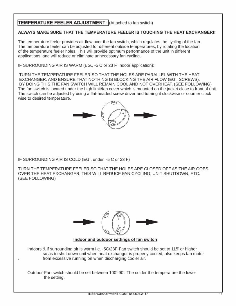
TEMPERATURE FEELER ADJUSTMENT: (Attached to fan switch)
ALWAYS MAKE SURE THAT THE TEMPERATURE FEELER IS TOUCHING THE HEAT EXCHANGER!!
The temperature feeler provides air flow over the fan switch, which regulates the cycling of the fan.The temperature feeler can be adjusted for different outside temperatures, by rotating the locationof the temperature feeler holes. This will provide optimum performance of the unit in differentapplications, and will reduce or eliminate unnecessary fan cycling.
IF SURROUNDING AIR IS WARM (EG., -5 C or 23 F, indoor application):
TURN THE TEMPERATURE FEELER SO THAT THE HOLES ARE PARALLEL WITH THE HEAT EXCHANGER, AND ENSURE THAT NOTHING IS BLOCKING THE AIR FLOW (EG., SCREWS). BY DOING THIS THE FAN SWITCH WILL REMAIN COOL AND NOT OVERHEAT. (SEE FOLLOWING)The fan switch is located under the high limit/fan cover which is mounted on the jacket close to front of unit.The switch can be adjusted by using a flat-headed screw driver and turning it clockwise or counter clock wise to desired temperature.
IF SURROUNDING AIR IS COLD (EG., under -5 C or 23 F)
TURN THE TEMPERATURE FEELER SO THAT THE HOLES ARE CLOSED OFF AS THE AIR GOESOVER THE HEAT EXCHANGER, THIS WILL REDUCE FAN CYCLING, UNIT SHUTDOWN, ETC.(SEE FOLLOWING)
.
Indoor and outdoor settings of fan switch
Indoors & if surrounding air is warm i.e. -5C/23F-Fan switch should be set to 115’ or higher so as to shut down unit when heat exchanger is properly cooled, also keeps fan motor from excessive running on when discharging cooler air.
Outdoor-Fan switch should be set between 100’-90’. The colder the temperature the lower the setting.
INSEROEQUIPMENT.COM | 855.604.2117 13

ELECTRODE SETTINGS FOR IDF350-II & IDF500 MODELS
SLIDE PLATE SETTINGS FOR IDF350-II & IDF500 MODELS
IDF350-II 4-5IDF500 6
INSEROEQUIPMENT.COM | 855.604.2117 14

JUNCTION BOX OF IDF350-II & IDF500
48006 GREEN LIGHT W/LEADS
48005 RED LIGHTS W/LEADS
48216 15 AMP BREAKER REPLACES FUSE & FUSEHOLDER
48184 CLEAR COVER FOR 48185B HONEYWELL CONTROLLER
INSEROEQUIPMENT.COM | 855.604.2117 15

THE SETTING OF THE “Z” DIMENSION ON IDF350-II & IDF500 MODELS
0 Install nozzle line assembly
• Insert the nozzle line assembly into the bumer air tube. Reference Figure 6.
• Slide the secondmy adjusting plate (Figure 7, item f) completely to the left on the indicator adjusting plate (item e) . Finger tighten acom nut (item c) to secure the two plates together. Slide both plates completely to the right (Indicator Plate will read 0) . Tighten fastener (item d) .
• Install the spline nut on the end of the nozzle line, leaving the nut loosely placed so the plates can be moved.
Figure 6 • Nozzle line assembly in bumer
CF800 1·3{4"'
0 Set dimension Z
500M
• Loo:;.e:n fastener c m Figurl!' -. Slide the nozzle line and plate assemblv until dimensiolll Z in Figun? 6 is: CH-00- 1-9116" :~::11 16''
CF800 - 1-.V.r' : Ll6'' .
\Vhen d.imeruio:c Z (from end of air tube to fiat area of front face of head) is correctly se t. tighten a~com. nut (item c).
• Atta~h the oi1 line from the oil , .ai,·e to the nozzle line end. Tigihten. se<:ourely.
• :Before proceeding. check dimension Z oJ:.oe agam. l oo; en acom nut ( mf J:.ece:;.sacy to rei!)l).:>ition the nozzle line. Oll!.ce dimension Z is ~et, do rror loose11 rfre r.<:onl mu (imuj (' cgai11. Note that for the ~tting of fastener d, mer to bJitial H r;atl Position procedure OD Page l l .
INSEROEQUIPMENT.COM | 855.604.2117 16

PRIMARY CONTROLS USED ON OHV HEATERS (PAST & PRESENT)
48185 WHITE ROGERSTHIS CONTROL HAS INSTANT LIGHT OFF (NO PRE PURGE) AND CONTINUOUS SPARK.
48185A-R8184 HONEYWELLSAME OPERATION AS THE WHITE ROGERS CONTROL.
48185B-R7184B HONEYWELLTHIS IS THE LATEST PRIMARY THAT HAS BEEN USED SINCE 2004. THERE IS TWO DIFFERENT MODELS THAT HAVE BEEN IN PRODUCTION, THE SERIES 4 & THE SERIES 5.THE SERIES 4HAD WIRES ONLY COMING OUT OF THE BOTTOMOF THE CONTROL. THIS CONTROL IS NO LONGER AVAILABLE & WAS REPLACED WITH THE SERIES 5. THE SERIES 5 HAS TERMINAL SPADES INSTEAD OF WIRES FOR EASE OF REPLACING. WHAT IS REQUIRED FOR CONVERSIONIS A STANDOFF ( P/N 48000)
INSEROEQUIPMENT.COM | 855.604.2117 17

Sequence of Operation of Honeywell R7184B Primary Control
1. STANDBY. The burner is idle, waiting for a call for heat. When a call for heat is initiated, there is a 5 second delay while control performs a safe start check.
2. VALVE-ON DELAY. The ignition and motor are turned on for a 15 second valve on delay. During this delay, the blower will circulate air through the heat exchanger, purging what ever fumes that have collected.
3. TRIAL FOR IGNITION (TFI) The fuel valve is opened. A flame should be established within the 15 second lockout time
4. LOCKOUT If flame is not sensed by the end of the TFI, the control shuts down on safety lockout and must be manually reset. If the control locks out three times in a row, the control enters restricted lockout. To reset , hold down reset button for 45 seconds until LED flashes twice.
5. IGNITION CARRYOVER Once flame is established, the ignition remains on for 10 seconds to ensure flame stability before turning off.
6. RUN The burner runs until the call for heat is satisfied. The burner is then shut down and sent to standby.
7. RECYCLE If the flame is lost while the burner is firing, the control shuts down the burner, enters a 60 second recycle delay, and then repeats the above ignition sequence. If flame is lost three times in a row, the control locks out to prevent cycling with repetitious flame loss due to poor combustion.
DISABLE FUNCTION
Any time the motor is running, press and hold the reset button to disable the burner. The burnerwill remain off as long as the button is held and will return to standby when released.
LED INDICATOR KEY
LED STATUS
On Flame sensed
Off Flame not sensed
Flashing ( ½ second on, Lockout/Restricted ½ second off) Lockout
Flashing (2 second on, Recycle 2 second off)
INSEROEQUIPMENT.COM | 855.604.2117 18

Burner StatesStandby: The burner is idle, waiting for a call for heat. Valve-On Delay: The igniter and motor are on while the control delays turning on
the oil solenoid valve for 45 seconds..
Trial For Ignition: The oil solenoid valve is energized. A flame should be established within the factory set trial for ignition time ("lockout time").
Lockout: The control has shut down for one of the following safety reasons:a. The trial for ignition (lockout) time expired without flame being established.b. The cad cell detected flame at the end of the Valve On Delay state.
To reset the control from lockout click the button 1-second.NOTE: A recurrence of the above failure modes or a failed welded relay check could cause
the control to enter a Hard Lockout state that must be reset only by a qualified service technician. To reset from Hard Lockout, hold the reset button for 15 seconds until the yellow light turns on.
Ignition Carryover: Once flame is established, the igniter remains on to ensure flame stability.
Run: The flame is sustained until the call for heat is satisfied. The burner is then sent to Motor-Off Delay, if applicable, or it is shut down and sent to Standby.
Recycle: If the flame is lost while the burner is firing, the control shuts down the burner,enters a 60 second recycle delay, and repeats the ignition sequence. The control will continue to Recycle each time the flame is lost, until it reaches a pre-set time allotment. The control will then go into Hard Lockout instead of recycle. This feature prevents excessive accumulation of oil in the appliance firing chamber.
Motor-Off Delay: If applicable, the oil solenoid valve is turned off and the control delays turning the motor off for the set motor-off delay time before the control returns to standby.
Pump Prime: The igniter and motor are on with the oil solenoid valve energized for 4 minutes. During Pump Prime mode, the cad cell is disregarded, allowing the technician to prime the pump without having to jumper the cad cell.
Sequence of Operation for Genisys Controller
INSEROEQUIPMENT.COM | 855.604.2117 19
<3~edett COMMERCIAL
13
2
'1 0
,/
17
fi
'12'
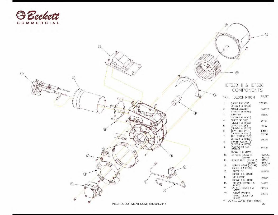
IDF350-II & IDFSOO COMPO~~ E~HS
~~0 . DESCR IPTi m~ PART
1. NOZZLE Ll fl E ASSY. B30258A (IDF350-II & IDF500)
2 AIRTUBE ASSEMBLY B30255A (IDF350-II & IOF500)
3. SPLINE NUT 848267 (IDF350-II & IDFSOD)
4. SUfJTEC "A" PUMP 48139 (IDF350-II & IOF500)
5. COPPER LINE (8") 48152 (IOF350-ll & IDF500)
6. COPPER LINE (11") 48152B (IDF350-ll & IOF500) B30798
7. FUEL SOLENOID VALVE (1DF350-II & IDF50D) 848250
8. BURNER HOUSING-"s" (IDF350-II & IDF50D)
9. PUMP /MOTOR FLEX COUPLING
B48133
(IDF350-ll & IDF500) I 0. AIR GU IDE ( IDF350-11) 830142A
(IDF500) 830142 II . BLOWER WH EEL (IOF350-11) 830141
(IDF500) 830141A 12. BURNER MOTOR (1/3 HP) 48140
(IDF350-II & IDF50D) 13. IGNITOR "S" B48 138A
(1DF350-ll & IDF500)
14. AIR SHUnER 848254 (IDF350-ll & IDF500}
15. AIR BAND (IDF350-II & 848253 IDF50D) .. CAD CELL (IDF350-II & 848154 IDF500)
17. BURfiER MOUfJTING 848252 FLANGE (IDF350-II & IDF500) .. CAD CELL LOCATED UIWER IGNITOR
INSEROEQUIPMENT.COM | 855.604.2117 20

IDF350-II & IDF500CF BURNER
ELECTRODE ASSEMBLY(PART #B20268)
NOZZLE LINE / OIL PIPE
BUSS BAR HOLDER
NOZZLE ADAPTERB48150
SOLID NOZZLE2.0-2.5 GPH - (#200)
0
B20262ELECTRODE INSULATOR KIT
INC. BUSS BARS & ELECTRODES
“A” PUMP (#48139) FOR IDF350-II & ALL IDF500
When replacing a fuel pump, ensure 1/16” by pass plug is installed in return port. Use a 5/32” allen wrench.
INSEROEQUIPMENT.COM | 855.604.2117 21
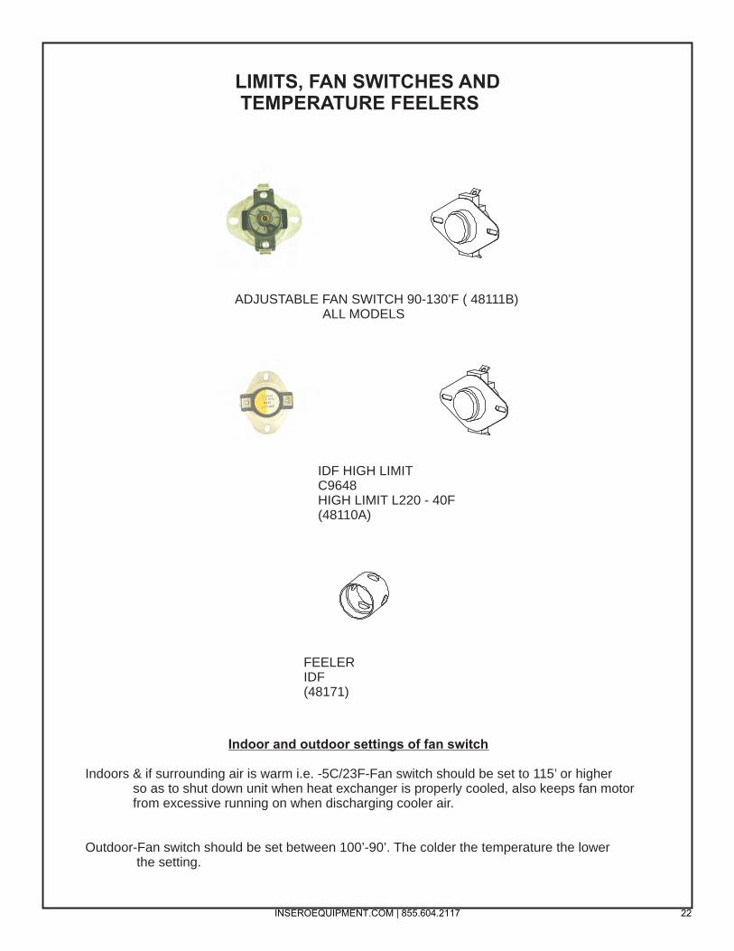
ADJUSTABLE FAN SWITCH 90-130’F ( 48111B) ALL MODELS
IDF HIGH LIMITC9648HIGH LIMIT L220 - 40F(48110A)
FEELER IDF(48171)
LIMITS, FAN SWITCHES AND TEMPERATURE FEELERS
Indoor and outdoor settings of fan switch
Indoors & if surrounding air is warm i.e. -5C/23F-Fan switch should be set to 115’ or higher so as to shut down unit when heat exchanger is properly cooled, also keeps fan motor from excessive running on when discharging cooler air.
Outdoor-Fan switch should be set between 100’-90’. The colder the temperature the lower the setting.
INSEROEQUIPMENT.COM | 855.604.2117 22
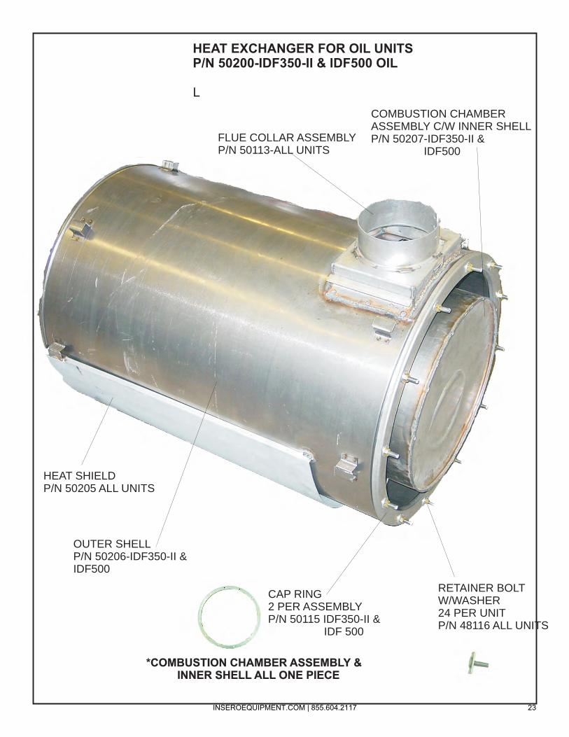
HEAT EXCHANGER FOR OIL UNITSP/N 50200-IDF350-II & IDF500 OIL
L
FLUE COLLAR ASSEMBLYP/N 50113-ALL UNITS
COMBUSTION CHAMBERASSEMBLY C/W INNER SHELLP/N 50207-IDF350-II & IDF500
RETAINER BOLT W/WASHER24 PER UNITP/N 48116 ALL UNITS
CAP RING2 PER ASSEMBLYP/N 50115 IDF350-II & IDF 500
OUTER SHELLP/N 50206-IDF350-II & IDF500
HEAT SHIELDP/N 50205 ALL UNITS
*COMBUSTION CHAMBER ASSEMBLY & INNER SHELL ALL ONE PIECE
INSEROEQUIPMENT.COM | 855.604.2117 23

POWER CORD48163 - #350
48163A - #500
JACKETASSEMBLY(IDF350-II, 500INNER 48204A OUTER 48204B
BURNER MOTOR
48140A-1/4 HP 350/500
MOTOR MOUNT & SCREEN 48803
FAN ENTRY PLATE48175
FLUE COLLARASSEMBLY
50113-#350/#500
HIGH LIMIT/FAN SWITCH COVER48112A
FRONT / SMALL COVER PANEL ASSEMBLY
(IDF350-II & 500)INNER 48119
OUTER 48119A
CANOPY ASSEMBLYWITH HANDLE
AND RAIN GUARD50108
OHV FROST-FIGHTERIDF350-II & IDF500
INSEROEQUIPMENT.COM | 855.604.2117 24

FRONT CAPASSEMBLY
48205B 12" X 248205AB 16" X 1
FRONTCAP
COLLAR48182
FUEL CAP48126A-350/500 (PLASTIC)
OUTER SHELLOF HEAT EXCHANGER
50206- #350/ #500
COMBUSTION CHAMBER50207 #350 - #500
WHEEL AND TIRE16“ WHEELS 48124A
CAP RING FOR HEATEXCHANGER
50115 - #350 / #500
CRADLEASSEMBLY
48120A-#350,#500
FUEL TANK ASSEMBLY(with drain plug and filler neck)48125B-#350, 500,48125 # 60020125-#200
IGNITOR B48138A 350/500
FAN MOTOR48101 - #35048202 - #50048202E-#500HS
FAN BLADE50103 - #35030203 - #500
50105 -500HS
IDF FROST-FIGHTER #350-II, #500
COMBUSTIONCHAMBER SEAL 48802
CART FOR POLY TANK50125ET
INSEROEQUIPMENT.COM | 855.604.2117 25

HEATER PARTS MANUAL


HT1010B PARTS MANUAL
Heater Exterior (A)
Reference Part Number Quantity Description
A1 NMC0000867 1 Engine Exhaust Beauty Ring
A2 P270532 1 Engine Exhaust Rain Cap
A3 30537 1 Electrical Receptacle Cover
A4 NMC0000992 1 Supply Side Duct Attachment
A5 MCL-13RB 2 Red Clearance Light
A6 MCL-13AB 2 Amber Clearance Light
A7 TPFF-022 1 Supply Side Panel
A8 TPFF-021 2 Storage Compartment Door
A9 M171A 2 3/4" Amber LED
A10 MCL-ABK 2 2" Amber LED
A11 140080 1 Jack
A12 18128XL 1 Adjustable Pintle Eye Receiver
A13 Reference 4 Corner Lifting Eye
INSEROEQUIPMENT.COM | 855.604.2117 26

HT1010B PARTS MANUAL
Heater Exterior (B)
Reference Part Number Quantity Description
B1 NMC0000864 2 Heater Exhaust Beauty Ring
B2 NMC0960005 2 Flue Pipe Rain Cap
B3 NMC0960004 2 Flue Pipe
B4 2402S-50 4 Door Latch
B5 NMC0090007 3 J-Lock Coupling
B6 TPFF-250 1 Return Side Door
B7 ST235-80-R16BE-S 2 Tire
B8 WH166-60E 2 Wheel
B9 81-931 1 Fuel Fill Cap Housing
B10 MCL-55RBK 2 2" Red LED
B11 M171R 5 3/4" Red LED
B12 439K 1 License Plate Light
B13 STL-23RBK 2 4" Red LED
B14 TPFF-023 1 Rear Door
B15 Reference 1 Center Lifting Eye
INSEROEQUIPMENT.COM | 855.604.2117 27

HT1010B PARTS MANUAL
Engine Compartment (C)
Reference Part Number Quantity Description
C1 NMC0000840 1 Placard; Warning; Do not operate in a confined space
C2 NMC0000846 1 Placard; Instruction; Engine Starting Procedures
C3 NMC0000855 1 Placard; Instruction; Using Shore Power
C4 CS6365N 1 Generator Plug
C5 282CSL1504 1 Generator
C6 NMC0000820 1 Generator Mount; Lower Piece
C7 NMC1190001 4 Vibration Isolator
C8 C1.5 T4 1 Engine
C9 NMC0000838 1 Placard; Warning; Do not use starting aids
C10 NMC1180001 1 Oil Drain Hose
C11 NMC0000863 1 Engine Mounting Spacer
C12 150-4142 1 Fuel Filter
C13 296-0888 1 Fuel Filter Primer Base
C14 M045237 1 Engine Muffler
C15 5P-1420 1 Fuel Supply Hose
C16 5P-9770 1 Fuel Return Hose
C17 246-5011 1 Air Filter (Inside Enclosure)
NS 271-5059 1 Indicator (Air Filter Service)
NS NMC0000839 1 Placard; Warning; Fire May Result
INSEROEQUIPMENT.COM | 855.604.2117 28

HT1010B PARTS MANUAL
Battery Components (D)
Reference Part Number Quantity Description
D1 8T-2910 2 Battery Hold-Down Wing nuts
D2 NMC0000876 1 Battery Hold-Down
D3 153-5700 1 Battery
D4 58X10 1 Ground Rod
D5 NMC0090011 2 Ground Rod Spring Clip
D6 GRC58 1 Ground Rod Clamp
D7 142-9459 2 Battery Hold-Down Bolts
D8 XTP456R 1 Positive Battery Cable
D9 XTP448BK 1 Negative Battery Cable
INSEROEQUIPMENT.COM | 855.604.2117 29

HT1010B PARTS MANUAL
Control Panel (E)
Reference Part Number Quantity Description
E1 F828A & F829A 2 Control Panel Mounts
E2 30090482 1 Control Panel
E3 NMC0000994 1 Control Panel Placard (E-stop)
INSEROEQUIPMENT.COM | 855.604.2117 30

HT1010B PARTS MANUAL
Accessories (F)
Reference Part Number Quantity Description
F1 NMC1120004 2 Interior Light
F2 NMC0000841 1 Placard; Caution; Stopping Unit
F3 NMC0000843 1 Placard; Instruction; Heater Maintenance
F4 GSS-6474 UZ 4 Gas Strut
NS NMC0000845 1 Light Mounting Bracket (Burner Compartment)
NS NMC0000875 1 Light Mounting Bracket (Engine Compartment)
*NS – Not shown in picture
INSEROEQUIPMENT.COM | 855.604.2117 31

HT1010B PARTS MANUAL
Trailer Components (G)
Reference Part Number Quantity Description
G1 JB10-170 1 7-Pole Junction Box
G2 140080 1 8000 LB Jack
G3 TC67-003 1 Trailer Wire Harness
G4 BA10-150 1 Breakaway Battery Kit
G5 CHA0020324 2 Trailer Chain
G6 18128XL 1 Adjustable Pintle Eye Receiver
INSEROEQUIPMENT.COM | 855.604.2117 32

HT1010B PARTS MANUAL
Electrical Components (H)
Reference Part Number Quantity Description
H1 SO 12/3 1 Electrical Outlet Cable
H2 AMP 602572 1 120V, 20A Duplex Receptacle
H3 SO 8/4 1 Generator Cable
H4 SO 12/3 2 Heater Cable
H5 BR24L70RP 1 Breaker Box
H6 BD2020 1 20A Duplex Breaker
H7 BR120 1 20A Breaker
H8 Reference - Breaker for Outlet
H9 Reference - Breaker for Front Heater
H10 Reference - Breaker for Rear Heater
INSEROEQUIPMENT.COM | 855.604.2117 33

HT1010B PARTS MANUAL
Accessories (I)
Reference Part Number Quantity Description
I1 NMC0170002 1 Fire Extinguisher and Bracket
I2 NMC1200001 1 Document Protector
INSEROEQUIPMENT.COM | 855.604.2117 34

HT1010B PARTS MANUAL
Burner Fuel System (J)
Reference Part Number Quantity Description
J1 NMC0000826 2 Fuel Filter Bracket
J2 NMC0320014 2 Fuel Filter Head
J3 NMC0210015 2 3/8" Hose Barb to 1/4" MNPT Elbow
J4 5P-1442 2 3/8" Fuel Supply/Return Hose
J5 NMC0320013 2 Fuel Filter
J6 48130 2 Fuel Hose (including MNPT elbow)
J7 5D-1026 8 3/8" Hose Clamp
J8 NMC0210014 2 3/8" Hose Barb to 3/8" FNPT Fitting
INSEROEQUIPMENT.COM | 855.604.2117 35

HT1010B PARTS MANUAL
Placards and Decals (K)
Part Number Quantity Description
NMC0000836 1 Warning: Hot!
NMC0000837 1 Warning: Sharp bends
NMC0000838 1 Warning: Do not use ether
NMC0000839 1 Warning: Fire may Result
NMC0000840 1 Warning: Don't Operate Inside
NMC0000841 1 Caution: To Stop Unit
NMC0000842 1 Danger: Shock hazard
NMC0000843 1 Instruction: Heater Maintenance
NMC0000844 4 Warning: Corner Lifting Eyes
NMC0000846 1 Instruction: Engine Starting Procedures
NMC0000847 1 Instruction: Heater Operation
NMC0000851 1 Warning: Remove Duct Covers
NMC0000852 1 Attention: No. 1 Diesel Fuel Only
NMC0000854 1 Fire Extinguisher Inside
NMC0000855 1 Instruction: Shore Power
NMC0000856 1 Ground Symbol Placard
NMC0000994 1 Control Panel Placard (E-Stop, Canada)
NMC0000853 1 Warning: Emergency Stop
NMC0000975 1 Canadian Compliance Placard
NMC0000976 1 Canadian Tire Info Placard
INSEROEQUIPMENT.COM | 855.604.2117 36


SCHEMATIC/WIRING
DOCUMENTS


HT1010B PARTS MANUAL
Trailer Harness Wiring Diagram (L)
Control Panel Wiring Diagram (M)
B+ 1B- 2
Fuel 3Start 4
Preheat 5Alt. 6
Hi temp 7Low OP 8
Light 9Remote E stop 10Remote E stop 11
B+ 12
P1 15 AMP
1
5019
17 AC30
13
5
5
10 AMP
15
4
4
2
10 AMP
19
129 HOUR
METER
+-
s
11 18
3316
18
AUTO SHUT-DOWN DEVICE
1 RED----------2 ORANGE----3 RED/BLACK-4 BROWN-----5 BLUE---------6 BLACK-------
LIGHT SWITCH
KEY SWITCH
E-STOP SWITCH
67
8
157
8
ALT.
WATER TEMP
OIL PRESS.
123456
J2 P2
15
37

HT1010B PARTS MANUAL
E-Stop and Air Intake Wiring Diagram (N)
B+ 1B- 2
ALT. (0R) 3RED/BLACK 4
BLACK/ WHITE 5WHITE 6
REMOTE E-STOP 7REMOTE E-STOP 8
REV GUARD
1 +
12 T
O 3
2 2
VD
C2
- N
EG
ATI
VE
3 S
IG. C
OM
.4
SIG
NA
L5
TES
T6 7 8
S500-A5MODULE
1 2 3 4 5 6
30 AMP
BULKHEAD 8PIN DEUTCH
P10
E-STOP SWITCH
BLK
WH
TR
ED
AU
X +
HO
TG
ND
57
57
51
52
53
54
55
56
52
585
8
38

HT1010B PARTS MANUAL
Engine Harness Wiring Diagram (O) F-826A
1 RED2 BLACK3 RED/ BLACK4 WHITE5 ORANGE6 YELLOW7 BLUE8 BROWN9 PURPLE10 NOT USED11 NOT USED12 RED
COOLANT OR TEMP SWITCH
ALTERNATOR CASE GROUND
ALTERNATOR B+
ALTERNATOR D+
BATT + ON STARTER
STARTER SOLENOID
GLOW PLUG RELAY
GLOW PLUG RELAY COIL
OIL PRESSURE SWITCH
FUEL SHUT OFF SOLENOID
B- GROUNDTO BLOCK
J1
WORK LIGHT
INSEROEQUIPMENT.COM | 855.604.2117 39

FAN MOTOR WIRING DIAGRAM
BALDOR MOTORS
From Unit From Unit
From Unit From Unit
Black
Blue
Orange
Black
White
Yellow
Brown
White
Red
J
2
8
1
3
4
Black
Blue
Orange
Black
White
White
Yellow
Red
1
3
5
2
8
WEG MOTORS
4
5
Black
Blue
Orange
Black
White
Brown
Red
1
3
5
2
8
7
White
Yellow 4
CHECK MOTOR RATING PLATE FOR APPLICABLE WIRING.
WEG MOTORS
INSEROEQUIPMENT.COM | 855.604.2117 40

14
IDF350-II & 500 WIRING DIAGRAM WITHHONEYWELL CONTROL
INSEROEQUIPMENT.COM | 855.604.2117 41

GREEN
_L -
GROUN D
IDF 350 & 500 WIRING DIAGRAM WITH GENISYS CONTROL
MALE PLUG / POLARilY ' ( 115V!:_"I60Hz) RI'1/ERSED
Ill R I
/ ' WHITE
START HELPER (OPTIONAL)
BLACK '4AAA; I WHITE 1 vvvvvvv 1
FAN I'M MOTOR
THERMOSTAT
c RED RED r> BLUE WHITE ~
THERMOSTAT 11-lERMOSTAT
BLACK RECEPTICLE
BLACK ' OFF ~ RED I @ MANUAL
WHITE I GREEN
(
_L
-GROUND
15AMP BURNER
FUSE HIGH LIMIT IGNITION CONTROL
(OR BREAKER) SWITCH
BLACK BLACK /'"':)., BLACK WHITE
~~- '<J LIMIT L2
FUEL PUMP TR MOTOR
JUMPER BURNER
ORANGE WHITE MOTOR
~TW
- IGNITON
FLAME ~ YELLOW TRANSFORMER
CAD BLUE WHITE DETECTOR CEll
' ' ' YELLOW 'II~-- ' ' ' IGNITERO
FUEL PUMP SOLENOID
RED L1 VALVE VIOLET WHITE
' /BURNER ON G
/ '
INSEROEQUIPMENT.COM | 855.604.2117 42

DIAGRAM WITH CHARGER
Electric Brake (Blue)
12-Volt Battery Lead (Black or Red)
BlackWhite
Ground (White)
Blue
Breakaway Box
A,B,C and D
are splices
Note: Wire By Function Only. Color Coding is Not Standard Among Manufacturers.
Cable
Breakaway
Switch
B
CA
D
Blue
DIAGRAM WITHOUT CHARGER
Electric Brake (Blue)
White
Ground (White)
Blue
Breakaway Box
A,B, and C are splices
Note: Wire By Function Only. Color Coding is Not Standard Among Manufacturers.
Cable
Breakaway
Switch
B
C
A
Blue
INSEROEQUIPMENT.COM | 855.604.2117 43

Que
stio
ns?
Cal
l tol
l fre
e 1-
800-
738-
8713
Bre
ak
aw
ay
Ba
tte
ry C
ha
rge
r
Ins
tall
ati
on
In
str
uc
tio
ns
fo
r:
LO
W C
HA
RG
ER
12
Vo
lt L
ea
d-A
cid
Ba
tte
ry
RE
AD
TH
IS F
IRS
T:
Ch
ec
k c
on
dit
ion
of
ba
tte
ry p
rio
r to
in
sta
lla
tio
n a
nd
pri
or
to e
ac
h t
rip
.
Rem
ove
Cha
rger
and
Bat
tery
from
the
batte
ry
case
.M
ount
bat
tery
cas
e se
cure
ly to
fram
e, ja
ck
post
or o
ther
sui
tabl
e lo
catio
n on
trai
ler.
Bol
t bre
akaw
ay s
witc
h to
fram
e of
trai
ler o
r ba
ttery
cas
e br
acke
t.C
heck
and
inst
all b
atte
ry a
nd c
harg
er in
to th
e ba
ttery
cas
e. F
eed
wire
s ou
t the
bac
k, th
en
clos
e th
e to
p.W
ire p
er s
chem
atic
dia
gram
. Pro
perly
insu
late
al
l con
nect
ions
.Fo
r Tec
hnic
al A
ssis
tanc
e an
d W
arra
nty
Info
rmat
ion
call:
1-8
00-7
86-7
968
Imp
ort
an
t F
ac
ts t
o R
em
em
be
r
Impr
oper
inst
alla
tion
of th
e br
eaka
way
bat
tery
w
ill d
estro
y th
e br
ake
cont
rol.
The
nega
tive
term
inal
mus
t atta
ch to
gro
und
and
pos
itive
te
rmin
al m
ust a
ttach
to th
e br
eaka
way
sw
itch.
Che
ck y
our b
rake
away
sys
tem
per
iodi
cally
to
insu
re th
at w
iring
and
con
nect
ions
are
sec
ure.
A sh
ort o
r an
open
circ
uit c
an re
sult
in a
no-
brak
e co
nditi
on.
If ex
cess
ive
disc
harg
ing
of th
e br
eaka
way
ba
ttery
occ
urs,
che
ck b
atte
ry a
nd re
char
ge
usin
g a
Hea
vy D
uty
Two
Sta
ge/M
aint
enan
ce
Cha
rger
. If u
sing
a c
omm
erci
al (A
C to
DC
) m
ake
certa
in th
e 12
vol
t cha
rge
is li
mite
d to
1.
2 am
ps o
r les
s.If
the
seco
ndar
y ba
ttery
nee
ds c
harg
ing,
cu
rren
t will
be
draw
n fro
m th
e to
w v
ehic
le's
ba
ttery
at a
nytim
e th
e to
w v
ehic
le is
con
nect
ed
to th
e tra
iler.
The
mos
t cur
rent
whi
ch w
ill b
e dr
awn
is 1
.2 a
mps
.To
onl
y ch
arge
the
brea
kaw
ay b
atte
ry w
hen
vehi
cle
is ru
nnin
g, a
bat
tery
isol
ator
may
be
inst
alle
d in
the
12 v
olt s
uppl
y lin
e (B
LAC
K
wire
for t
ow c
harg
er).
12 V
olt
Seale
d L
ead
-Acid
Batt
ery
To
maxim
ize t
he l
ife o
f th
e b
att
ery
th
e f
oll
ow
ing
co
nd
itio
ns s
ho
uld
be m
et:
Avoi
d ov
er o
r und
erch
arge
. Thi
s is
the
sing
lew
orst
ene
my
of le
ad-a
cid
batte
ries.
Bat
terie
s sh
ould
not
be
stor
ed in
a d
isch
arge
dst
ate
or a
t ele
vate
d am
bien
t tem
pera
ture
s.Av
oid
expo
sing
bat
terie
s to
hea
t! S
ervi
ce li
feis
sho
rtene
d co
nsid
erab
ly a
t am
bien
t abo
ve30
deg
rees
C (8
6 de
gree
s F)
.D
ue to
the
char
acte
ristic
s of
this
bat
tery
, afte
rsi
x to
nin
e m
onth
s of
sto
rage
, the
bat
ter
shou
ld b
e re
char
ged.
Cha
rge
the
batte
ry a
t the
pro
per r
ate.
Cur
rent
shou
ld b
e lim
ited
to 1
.2 a
mps
or l
ess.
Cha
rge
curr
ent a
bove
2.3
am
ps w
ill re
sult
in s
horte
ned
serv
ice
life.
Pro
vide
ade
quat
e ai
r circ
ulat
ion
whe
nch
argi
ng b
atte
ry. D
o no
t cha
rge
batte
ry in
any
othe
r con
tain
er b
esid
es th
e su
pplie
d ba
ttery
box.
Do
not p
lace
bat
terie
s in
clo
se p
roxi
mity
toob
ject
s w
hich
can
pro
duce
spa
rks
or fl
ames
.D
o no
t exp
ose
batte
ry c
ase
to o
rgan
ic s
olve
nts
or a
dhes
ives
.D
o no
t atte
mpt
to d
isas
sem
ble
batte
ries.
Con
tact
with
sul
furic
aci
d m
ay c
ause
har
m.
Fast
en b
atte
ries
tight
ly a
nd m
ake
prov
isio
ns fo
r sho
ck a
bsor
ptio
n if
expo
sure
to s
hock
or v
ibra
tion
is li
kely
.D
o no
t thr
ow b
atte
ries
into
fire
; bat
terie
s so
disp
osed
may
rupt
ure
or e
xplo
de.
12 V
OLT
P/N
102
3 - 4
am
p/hr
- m
ax d
isch
arge
cur
rent
20 h
r. ra
te =
225
mA
P/N
202
3 - 5
am
p/hr
- m
ax d
isch
arge
cur
rent
20 h
r. ra
te =
250
mA
Max
imum
Dis
char
ge C
urre
nt =
40
amps
Max
imum
cha
rge
curr
ent m
ust b
e lim
ited
to
1.2
amps
P/N
102
3, P
/N 2
023:
Leng
th =
3.5
4" W
idth
= 2
.76"
Hei
ght =
4.1
3"W
eigh
t = 3
.8 lb
sTe
rmin
als:
Fas
ten
Tab
.187
" x .0
32"
Ser
vice
Life
:U
nder
nor
mal
ope
ratin
g co
nditi
ons.
4-5
year
s in
sta
ndby
app
licat
ions
or 2
00-1
000
char
ge/d
isch
arge
cyc
les
depe
ndin
g up
on d
epth
of d
isch
arge
and
rate
of c
harg
e.
Ba
tte
ry D
ata
Ch
art
HE
AV
Y D
UT
Y Q
UIC
K/M
AIN
TE
NA
NC
E T
WO
STA
GE
CH
AR
GE
R
TOW
VE
HIC
LEC
HA
SS
IS G
RO
UN
D
Aut
omat
icR
eset
Circ
uit
Bre
aker
++1
2 Vo
ltB
atte
ry -
+ 12
Vol
t Sys
tem
Sto
p Li
ght S
witc
h
RE
D
BLA
CK
+ 12
VB
LAC
K (+
)T
OW
CH
AR
GE
R
RE
D (+
)
+ 12
Vol
tB
reak
away
Bat
tery
+-
TRA
ILE
RB
RA
KE
S
Bre
akaw
ayS
witc
h
BLU
EB
LUETOW VEHICLE
TRAILER
Bra
keC
ontro
l
WHITE
BLU
E
INSEROEQUIPMENT.COM | 855.604.2117 44

TROUBLE SHOOTING


O.H.V. TROUBLE SHOOTING GUIDE
ALWAYS DOUBLE CHECK FOR SUFFICIENT POWER , GAUGE OF CORD (SEE TOP OF PAGE #3) ANDPROPER FUEL SUPPLY. POWER AND FUEL SUPPLY MUST BE SHUT OFF/DISCONNECTED BEFORE
REMOVING OR REPLACING ANY COMPONENTS ON THE HEATER. 1. Unit is turned on, nothing happens after 5 second safe start.
a. Ensure proper voltage coming in, 115V AC.b. Check for power on both sides of burner fuse. If no power, then check toggle switch. If
power on one side, replace fuse. If power on both sides, go to c.c. Check black wire from primary control. If no power there, remove high limit cover &
check for power on both sides of high limit. If power on one side only, replace high limit.If power on both sides, go to d.
d. Ensure thermostat contacts on primary control ( T and T) are jumpered out.e. Make sure light on primary control is not flashing. If so, push button to reset.f. Check manual reset button on motor and wiring connection to motor. If reset pushed
and power going to motor, nothing is happening, replace burner motor.g. On neutral line ( white wires) make sure all connections are tight and secure, and unit is
properly grounded. With AC voltage tester, check white (neutral lines) for power (one onground, one on neutral). If over 5 volts, check polarity. If polarity correct, check wiresindividually for power to determine leak source, then replace leak source.
h. If power coming into black wire on primary control, but no power out to orange wire,replace primary control.
i. If green light on primary control stays on, check to ensure transformer door is closedproperly as cad cell is detecting light. Check cad cell is working. If light stays on and noobvious areas open, check OHM reading across two yellow wires. If you get a reading,replace cad cell. If you get no OHM reading from cad cell, replace primary control if lightstill on.
2. Burner motor starts but unit will not fire.a. Check for power on blue wire on primary control going to ignitor. If no power there,
replace primary control if powered, go to b.b. Remove electrode assembly and check isolators for cracks or chips in the porcelain.
Make sure electrode setting is proper. For electrode adjustments, please turn to page8.Clean assembly if there is any soot or oil..
c The nozzle should be checked and ensure it is not clogged or blocked. Make sure nozzle is not loose.d. Ensure air shutters are properly set to factory specifications.e. Check for power on violet line on primary control. After pre-purge, if no power sent to
violet line, replace primary control. If power on violet line, remove copper fuel line atelectrode assembly to ensure fuel is coming out. If no fuel there, replace solenoid valve.
f. At the bleeder screw, check for proper out pump pressure ( see maintenance section). Iflow or no pump pressure, go to g
g Check oil filter, oil pick up tube and oil lines to ensure free flow and they are not clogged or dirty.h Check electrical polarity and grounding.
3. Burner fires then locks out.a. Check oil pressure to ensure solenoid valve is opening. Check oil flow system, filter,
pick up tubes and lines.b. The nozzle should be checked to ensure it is clean and emitting a good spray pattern,
as this could affect the cad cell operation.c. Cad cell (flame detector) could be defective. Disconnect yellow cad cell wires from
primary control. Start unit and when it fires, connect jumper across connections onprimary control. If unit continues to run, then check cad cell alignment with burner, cleanface with a soft cloth and ensure no external light is affecting it. With an ohmmeter,check resistance across cad cell leads with machine running and primary control cadcell leads jumpered out. If resistance over 1200 OHMS, cad cell should be replaced. Ifunit locks out with jumper, replace primary control.
INSEROEQUIPMENT.COM | 855.604.2117 45

O.H.V. TROUBLE SHOOTING GUIDE
3. d. Wires between cad cell and primary control should be checked to see that they are not pinched or crimped..
e. Prime fuel pump by loosening bleeder screw till steady stream of fuel comes out to ensure no air or bubbles in fuel line..f. If unit locks out three times in succession, it will go into restricted lock out mode. To reset, hold down reset button for 45 seconds until LED flashed twice. The unit will then resume in normal operating mode. After verifying primary control is not in lockout & light continues to flash, replace primary control.g. Check polarity, ground & voltage must be between 108-132v AC.h. Make sure high limit is functioning properly.
4. Smoky firea. Check nozzle, make sure is tight and not clogged.b. Check combustion chamber for cracks or burnt out. c. Check air band settings. (Air shutter and/or air band may be closed too much-restricting combustion air.d. Check pump pressure.e. Check slide plate to make sure it is in correct position.( See page 8 for settings)If necessary, open slightly.
5. Delayed ignitiona. Check for proper electrode setting. b. Check the isolators for cracks or a conducting coat of soot or oil. Cracks sometimes occur under the electrode bracket, causing a short circuit.c. Check to see that the air shutter is not overly open-too much air will blow out flame.d. Check to ensure pump pressure is properly set..e. Change nozzle.f. Check fuel filter, replace if necessary.g. Ensure that draft or wind is not blowing out flame-add 3’ stack.
6. Main fan will not come on, unit shuts down on high limit..a. Check temperature feeler, make sure it is in properly.b. Jumper out fan switch to test motor. If you have voltage to motor and still does not start, replace motor. Check line voltage to ensure proper voltage. Also checks amp draw on motor, motor may be running too hot and not run due to thermal overload being tripped.c. Replace fan switch if you have power on one side after unit heating up it does not make.d. Replace high limit as it may be tripping too soon and not giving fan switch time to engage.e. Ensure fan switch temperature is correct for weather conditions ( see page 7 for settings)
7 Unit on, but cycles on high limita. Check air flow, ensure both ducts are in place and clear of obstruction and straight.b. Check pump pressure, unit could be over firing.c. Check nozzle that proper size of nozzle is installed.d. Change high limit.e. Maximum duct length with 2 X 12” outlet is 24’ on each side. 1 X 16” outlet , length is 45’. Any longer will create back pressure in the unit and trip the high limit.* SEE PAGE 2 FOR SPECS*
8 Combustion chamber turns red.a. Nozzle may be firing side ways (replace or adjust)b. Clogged nozzle ( replace)c. Temperature feeler not on properly or missing ( Must be touching heat exchanger)d. High limit not functioning ( replace)e. Excessive pump pressure. Check and reset if necessary.
INSEROEQUIPMENT.COM | 855.604.2117 46