operation and maintenance manual - · pdf fileoperation and maintenance manual ......
TRANSCRIPT
Operation and Maintenance Manual
Aquaflair™ Modulating Air-cooled Chillers, Free-cooling Chillers and Heat Pumps
Uniflair™ ISAC, ISAF, ISAH, ISCC, ISCF, ISCH
Models 0621A, 0921A, 1221A
990-9874-001
06MC0104@00B0120
Publication Date: April 2016

Schneider Electric IT Corporation Legal DisclaimerThe information presented in this manual is not warranted by the Schneider Electric IT Corporation to be authoritative, error free, or complete. This publication is not meant to be a substitute for a detailed operational and site specific development plan. Therefore, Schneider Electric IT Corporation assumes no liability for damages, violations of codes, improper installation, system failures, or any other problems that could arise based on the use of this Publication.
The information contained in this Publication is provided as is and has been prepared solely for the purpose of evaluating data center design and construction. This Publication has been compiled in good faith by Schneider Electric IT Corporation. However, no representation is made or warranty given, either express or implied, as to the completeness or accuracy of the information this Publication contains.
IN NO EVENT SHALL SCHNEIDER ELECTRIC IT CORPORATION, OR ANY PARENT, AFFILIATE OR SUBSIDIARY COMPANY OF SCHNEIDER ELECTRIC IT CORPORATION OR THEIR RESPECTIVE OFFICERS, DIRECTORS, OR EMPLOYEES BE LIABLE FOR ANY DIRECT, INDIRECT, CONSEQUENTIAL, PUNITIVE, SPECIAL, OR INCIDENTAL DAMAGES (INCLUDING, WITHOUT LIMITATION, DAMAGES FOR LOSS OF BUSINESS, CONTRACT, REVENUE, DATA, INFORMATION, OR BUSINESS INTERRUPTION) RESULTING FROM, ARISING OUT, OR IN CONNECTION WITH THE USE OF, OR INABILITY TO USE THIS PUBLICATION OR THE CONTENT, EVEN IF SCHNEIDER ELECTRIC IT CORPORATION HAS BEEN EXPRESSLY ADVISED OF THE POSSIBILITY OF SUCH DAMAGES. SCHNEIDER ELECTRIC IT CORPORATION RESERVES THE RIGHT TO MAKE CHANGES OR UPDATES WITH RESPECT TO OR IN THE CONTENT OF THE PUBLICATION OR THE FORMAT THEREOF AT ANY TIME WITHOUT NOTICE.
Copyright, intellectual, and all other proprietary rights in the content (including but not limited to software, audio, video, text, and photographs) rests with Schneider Electric IT Corporation or its licensors. All rights in the content not expressly granted herein are reserved. No rights of any kind are licensed or assigned or shall otherwise pass to persons accessing this information.
This Publication shall not be for resale in whole or in part.
Table of Contents
Safety.................................................................................1
Important Safety Information . . . . . . . . . . . . . . . . . . . . . . . . . . . . . . . . . 1
Safety During Operation . . . . . . . . . . . . . . . . . . . . . . . . . . . . . . . . . . . . . 2
General Information...........................................................4
Overview. . . . . . . . . . . . . . . . . . . . . . . . . . . . . . . . . . . . . . . . . . . . . . . . . 4
Cross-reference symbol used in this manual . . . . . . . . . . . . . . .4Manual updates . . . . . . . . . . . . . . . . . . . . . . . . . . . . . . . . . . . . . .4Compliance . . . . . . . . . . . . . . . . . . . . . . . . . . . . . . . . . . . . . . . . .4Symbols on the Unit . . . . . . . . . . . . . . . . . . . . . . . . . . . . . . . . . .5
Commissioning ..................................................................6
Check Lists . . . . . . . . . . . . . . . . . . . . . . . . . . . . . . . . . . . . . . . . . . . . . . . 6
Initial inspection . . . . . . . . . . . . . . . . . . . . . . . . . . . . . . . . . . . . . .6Free-cooling version . . . . . . . . . . . . . . . . . . . . . . . . . . . . . . . . . .6Start-up . . . . . . . . . . . . . . . . . . . . . . . . . . . . . . . . . . . . . . . . . . . .7Heating the oil . . . . . . . . . . . . . . . . . . . . . . . . . . . . . . . . . . . . . . .7
Operation...........................................................................8
Microprocessor Control . . . . . . . . . . . . . . . . . . . . . . . . . . . . . . . . . . . . . 8
General features . . . . . . . . . . . . . . . . . . . . . . . . . . . . . . . . . . . . .8
Display Interface. . . . . . . . . . . . . . . . . . . . . . . . . . . . . . . . . . . . . . . . . . . 9
Language selection . . . . . . . . . . . . . . . . . . . . . . . . . . . . . . . . . . .9Program identification . . . . . . . . . . . . . . . . . . . . . . . . . . . . . . . .10Display information . . . . . . . . . . . . . . . . . . . . . . . . . . . . . . . . . .10Pre-operation symbols . . . . . . . . . . . . . . . . . . . . . . . . . . . . . . .10Operation symbols . . . . . . . . . . . . . . . . . . . . . . . . . . . . . . . . . .11
Unit Start-up Conditions . . . . . . . . . . . . . . . . . . . . . . . . . . . . . . . . . . . . 11
Turning the Unit On and Off . . . . . . . . . . . . . . . . . . . . . . . . . . . . . . . . . 11
Automatic mode . . . . . . . . . . . . . . . . . . . . . . . . . . . . . . . . . . . .12Turning off the unit . . . . . . . . . . . . . . . . . . . . . . . . . . . . . . . . . .12Adjusting parameters . . . . . . . . . . . . . . . . . . . . . . . . . . . . . . . .12
Uniflair ISA*, ISC* Operation and Maintenance Manual i
Unit Configuration . . . . . . . . . . . . . . . . . . . . . . . . . . . . . . . . . . . . . . . . 12
Unit on/off . . . . . . . . . . . . . . . . . . . . . . . . . . . . . . . . . . . . . . . . 12Input/Output . . . . . . . . . . . . . . . . . . . . . . . . . . . . . . . . . . . . . . 12Setpoint remote . . . . . . . . . . . . . . . . . . . . . . . . . . . . . . . . . . . . 13Alarms history . . . . . . . . . . . . . . . . . . . . . . . . . . . . . . . . . . . . . 13Software information . . . . . . . . . . . . . . . . . . . . . . . . . . . . . . . . 13pLan network status . . . . . . . . . . . . . . . . . . . . . . . . . . . . . . . . 13
Settings Menu . . . . . . . . . . . . . . . . . . . . . . . . . . . . . . . . . . . . . . . . . . . 14
Operative settings . . . . . . . . . . . . . . . . . . . . . . . . . . . . . . . . . . 14Set-back cycle . . . . . . . . . . . . . . . . . . . . . . . . . . . . . . . . . . . . . 15Hour meter settings . . . . . . . . . . . . . . . . . . . . . . . . . . . . . . . . . 15Manual defrost . . . . . . . . . . . . . . . . . . . . . . . . . . . . . . . . . . . . . 15
Summer and Winter Commutation. . . . . . . . . . . . . . . . . . . . . . . . . . . . 16
Automatic . . . . . . . . . . . . . . . . . . . . . . . . . . . . . . . . . . . . . . . . 16From the user terminal keyboard . . . . . . . . . . . . . . . . . . . . . . 16From digital input . . . . . . . . . . . . . . . . . . . . . . . . . . . . . . . . . . . 16From BMS supervisor . . . . . . . . . . . . . . . . . . . . . . . . . . . . . . . 16
Heat Recovery . . . . . . . . . . . . . . . . . . . . . . . . . . . . . . . . . . . . . . . . . . . 17
Clock and Calendar Settings . . . . . . . . . . . . . . . . . . . . . . . . . . . . . . . . 18
Modbus Communication Status . . . . . . . . . . . . . . . . . . . . . . . . . . . . . . 19
Service Menu . . . . . . . . . . . . . . . . . . . . . . . . . . . . . . . . . . . . . . . . . . . . 19
Hardware settings . . . . . . . . . . . . . . . . . . . . . . . . . . . . . . . . . . 19Ultracapacitor . . . . . . . . . . . . . . . . . . . . . . . . . . . . . . . . . . . . . 24Software settings . . . . . . . . . . . . . . . . . . . . . . . . . . . . . . . . . . . 25Sensor calibration . . . . . . . . . . . . . . . . . . . . . . . . . . . . . . . . . . 33Memory operations . . . . . . . . . . . . . . . . . . . . . . . . . . . . . . . . . 34Manual control . . . . . . . . . . . . . . . . . . . . . . . . . . . . . . . . . . . . . 35Serial communications . . . . . . . . . . . . . . . . . . . . . . . . . . . . . . 37Alarm addressing . . . . . . . . . . . . . . . . . . . . . . . . . . . . . . . . . . 38
Network Configuration .....................................................39
Overview . . . . . . . . . . . . . . . . . . . . . . . . . . . . . . . . . . . . . . . . . . . . . . . 39
pLAN address settings . . . . . . . . . . . . . . . . . . . . . . . . . . . . . . 40Configuring the pLAN address . . . . . . . . . . . . . . . . . . . . . . . . 40Terminal and pCO addresses . . . . . . . . . . . . . . . . . . . . . . . . . 44
pLAN Connections Between the Units. . . . . . . . . . . . . . . . . . . . . . . . . 45
Remote Control of the Terminal with pLAN . . . . . . . . . . . . . . . . . . . . . 46
LAN and Supervision Connection Cable . . . . . . . . . . . . . . . . . . . . . . . 50
Viewing the Network from the Terminal . . . . . . . . . . . . . . . . . . . . . . . . 50
ii Uniflair ISA*, ISC* Operation and Maintenance Manual
LAN Settings. . . . . . . . . . . . . . . . . . . . . . . . . . . . . . . . . . . . . . . . . . . . . 51
EXV Settings . . . . . . . . . . . . . . . . . . . . . . . . . . . . . . . . . . . . . . . . . . . . 52
Parameter settings . . . . . . . . . . . . . . . . . . . . . . . . . . . . . . . . . .53
Alarm Reading . . . . . . . . . . . . . . . . . . . . . . . . . . . . . . . . . . . . . . . . . . . 54
Triggered alarms . . . . . . . . . . . . . . . . . . . . . . . . . . . . . . . . . . . .54Alarm descriptions . . . . . . . . . . . . . . . . . . . . . . . . . . . . . . . . . . .54
Default Value Procedure . . . . . . . . . . . . . . . . . . . . . . . . . . . . . . . . . . . 62
Configuration parameters . . . . . . . . . . . . . . . . . . . . . . . . . . . . .62Numeric parameters . . . . . . . . . . . . . . . . . . . . . . . . . . . . . . . . .65
Technical Data.................................................................70
Refrigerant Content . . . . . . . . . . . . . . . . . . . . . . . . . . . . . . . . . . . . . . . 70
Water Circuit Capacity . . . . . . . . . . . . . . . . . . . . . . . . . . . . . . . . . . . . . 70
Recommended plant capacity . . . . . . . . . . . . . . . . . . . . . . . . . .70
Maximum Operating Hydraulic Pressure . . . . . . . . . . . . . . . . . . . . . . . 71
Compressor Oil. . . . . . . . . . . . . . . . . . . . . . . . . . . . . . . . . . . . . . . . . . . 71
Safety Device Calibration . . . . . . . . . . . . . . . . . . . . . . . . . . . . . . . . . . . 71
Troubleshooting...............................................................72
Default Values Update and Protocol Variables................75
Maintenance ....................................................................76
Safety During Maintenance Work. . . . . . . . . . . . . . . . . . . . . . . . . . . . . 76
Refrigerant . . . . . . . . . . . . . . . . . . . . . . . . . . . . . . . . . . . . . . . . . . . . . . 76
Creating a vacuum in the circuit . . . . . . . . . . . . . . . . . . . . . . . .76Filling with refrigerant . . . . . . . . . . . . . . . . . . . . . . . . . . . . . . . .76
Check the Compressor Oil Level . . . . . . . . . . . . . . . . . . . . . . . . . . . . . 77
Double Power Supply . . . . . . . . . . . . . . . . . . . . . . . . . . . . . . . . . . . . . . 78
Low External Air Temperature . . . . . . . . . . . . . . . . . . . . . . . . . . . . . . . 79
Units with free-cooling . . . . . . . . . . . . . . . . . . . . . . . . . . . . . . . .79Units without free-cooling . . . . . . . . . . . . . . . . . . . . . . . . . . . . .79
Scheduled Maintenance Guidelines . . . . . . . . . . . . . . . . . . . . . . . . . . . 79
iiiUniflair ISA*, ISC* Operation and Maintenance Manual
Quarterly Checks . . . . . . . . . . . . . . . . . . . . . . . . . . . . . . . . . . . . . . . . . 79
Semi-annual Checks . . . . . . . . . . . . . . . . . . . . . . . . . . . . . . . . . . . . . . 80
Annual Checks. . . . . . . . . . . . . . . . . . . . . . . . . . . . . . . . . . . . . . . . . . . 80
Other Checks . . . . . . . . . . . . . . . . . . . . . . . . . . . . . . . . . . . . . . . . . . . . 80
iv Uniflair ISA*, ISC* Operation and Maintenance Manual


Safety
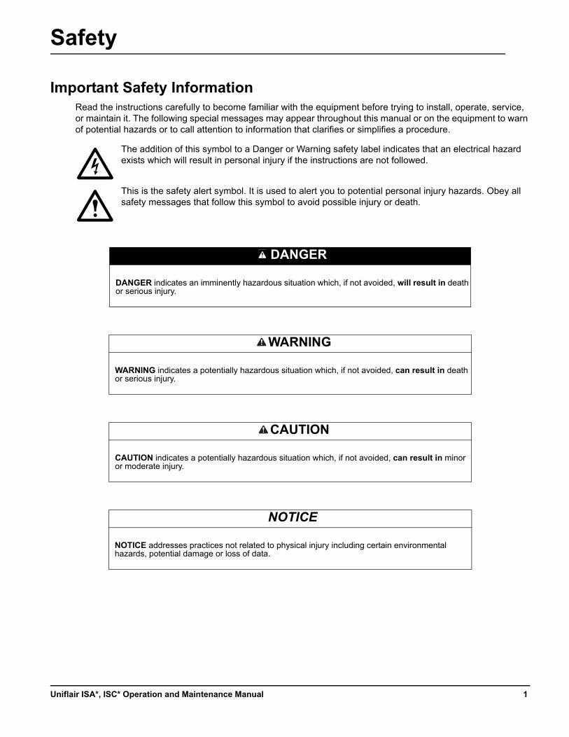
Important Safety InformationRead the instructions carefully to become familiar with the equipment before trying to install, operate, service, or maintain it. The following special messages may appear throughout this manual or on the equipment to warn of potential hazards or to call attention to information that clarifies or simplifies a procedure.
The addition of this symbol to a Danger or Warning safety label indicates that an electrical hazard exists which will result in personal injury if the instructions are not followed.
This is the safety alert symbol. It is used to alert you to potential personal injury hazards. Obey all safety messages that follow this symbol to avoid possible injury or death.
DANGER
DANGER indicates an imminently hazardous situation which, if not avoided, will result in death or serious injury.
WARNING
WARNING indicates a potentially hazardous situation which, if not avoided, can result in death or serious injury.
CAUTION
CAUTION indicates a potentially hazardous situation which, if not avoided, can result in minor or moderate injury.
NOTICE
NOTICE addresses practices not related to physical injury including certain environmental hazards, potential damage or loss of data.
1Uniflair ISA*, ISC* Operation and Maintenance Manual
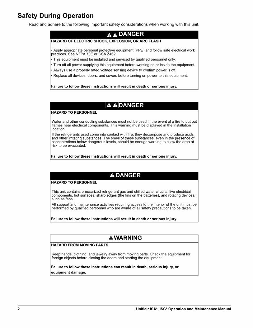
Safety During OperationRead and adhere to the following important safety considerations when working with this unit.
DANGERHAZARD OF ELECTRIC SHOCK, EXPLOSION, OR ARC FLASH
• Apply appropriate personal protective equipment (PPE) and follow safe electrical work practices. See NFPA 70E or CSA Z462.
• This equipment must be installed and serviced by qualified personnel only.
• Turn off all power supplying this equipment before working on or inside the equipment.
• Always use a properly rated voltage sensing device to confirm power is off.
• Replace all devices, doors, and covers before turning on power to this equipment.
Failure to follow these instructions will result in death or serious injury.
DANGERHAZARD TO PERSONNEL
Water and other conducting substances must not be used in the event of a fire to put out flames near electrical components. This warning must be displayed in the installation location.
If the refrigerants used come into contact with fire, they decompose and produce acids and other irritating substances. The smell of these substances, even in the presence of concentrations below dangerous levels, should be enough warning to allow the area at risk to be evacuated.
Failure to follow these instructions will result in death or serious injury.
DANGERHAZARD TO PERSONNEL
This unit contains pressurized refrigerant gas and chilled water circuits, live electrical components, hot surfaces, sharp edges (the fins on the batteries), and rotating devices, such as fans.
All support and maintenance activities requiring access to the interior of the unit must be performed by qualified personnel who are aware of all safety precautions to be taken.
Failure to follow these instructions will result in death or serious injury.
WARNINGHAZARD FROM MOVING PARTS
Keep hands, clothing, and jewelry away from moving parts. Check the equipment for foreign objects before closing the doors and starting the equipment.
Failure to follow these instructions can result in death, serious injury, or
equipment damage.
Uniflair ISA*, ISC* Operation and Maintenance Manual2
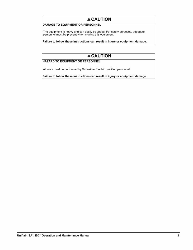
CAUTIONDAMAGE TO EQUIPMENT OR PERSONNEL
The equipment is heavy and can easily be tipped. For safety purposes, adequate personnel must be present when moving this equipment.
Failure to follow these instructions can result in injury or equipment damage.
CAUTIONHAZARD TO EQUIPMENT OR PERSONNEL
All work must be performed by Schneider Electric qualified personnel.
Failure to follow these instructions can result in injury or equipment damage.
3Uniflair ISA*, ISC* Operation and Maintenance Manual
General Information
Overview
Cross-reference symbol used in this manual
See another section of this document or another document for more information on this subject.
Manual updates
Check for updates to this manual on the Schneider Electric Web site, www.schneider-electric.com/support. Select the Download Documents and Software link under the Support tab and enter the manual part number or SKU for your equipment in the search field. See the back cover of this manual for the part number.
Compliance
This unit underwent the risk analysis in compliance with Machinery Directive 2006/42/EC. The technical solutions implemented during the design phase are described in the unit's technical documentation. The appliance was built to operate safely in the areas of application for which it was designed, provided its installation, commissioning and maintenance are performed in compliance with the instructions provided in this manual and on the labels affixed to the unit.
In compliance with European Community Directive 94/9/EC, these units must not be used in potentially explosive atmospheres. In any case, always abide strictly by the applicable laws in force in the place of installation of the system.
Pressurised equipment: This appliance is subject to European Community Directive 97/23/EC concerning Pressurised Equipment. Any and all work performed on the pressure circuit must be expressly authorised by Schneider Electric and personnel must be approved by Schneider Electric. If any one of the following components: compressors, liquid tanks, safety valves, cooling pressure switches needs to be replaced, immediate notification of the serial number of the new device and of the replaced device must be sent to Schneider Electric, otherwise Schneider Electric will not guarantee the entire appliance.
What's more, should it be necessary to replace any welded joint on site, Schneider Electric must be notified immediately of which joint needs repairing and the name of the technician performing the repair work must be notified.
Uniflair ISA*, ISC* Operation and Maintenance Manual4
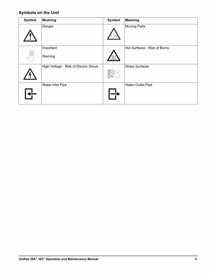
Symbols on the Unit
Symbol Meaning Symbol Meaning
Danger Moving Parts
Important
Warning
Hot Surfaces - Risk of Burns
High Voltage - Risk of Electric Shock Sharp Surfaces
Water Inlet Pipe Water Outlet Pipe
5Uniflair ISA*, ISC* Operation and Maintenance Manual
Commissioning
Check Lists
Initial inspection
After installation, complete the following checklists to verify that all components are properly installed, the location of the chiller has been properly prepared, and the chiller is free of damage.
Once installation is complete, perform the following checks:
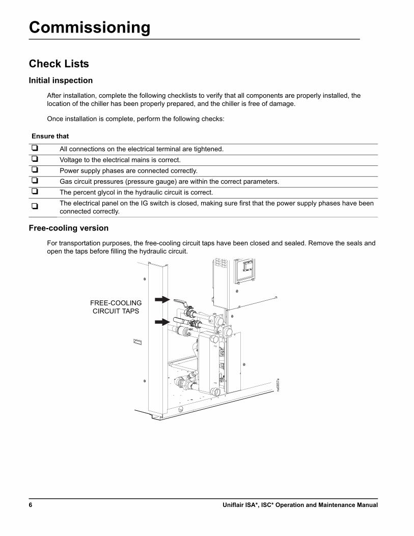
Free-cooling version
For transportation purposes, the free-cooling circuit taps have been closed and sealed. Remove the seals and open the taps before filling the hydraulic circuit.
Ensure that
All connections on the electrical terminal are tightened.
Voltage to the electrical mains is correct.
Power supply phases are connected correctly.
Gas circuit pressures (pressure gauge) are within the correct parameters.
The percent glycol in the hydraulic circuit is correct.
The electrical panel on the IG switch is closed, making sure first that the power supply phases have been connected correctly.
na58
57a
FREE-COOLING CIRCUIT TAPS
Uniflair ISA*, ISC* Operation and Maintenance Manual6
Start-up
Heating the oil
After powering the chiller (IG set to ON, IM9 closed, and unit turned off from control), wait at least 12 hours before the season start-up of the system in order to heat up the compressor oil sufficiently.
Do not disconnect the unit from the power supply for weekly stops.
During prolonged stops, the refrigerant may migrate spontaneously into the compressor casings, which on start-up may cause the oil to foam and damage due to lack of lubrication.
NOTICEHAZARD TO EQUIPMENT
Before starting the unit, read “Semi-hermetic screw compressor start-up procedure” on page 7.
Failure to follow these instructions can result in equipment damage.
7Uniflair ISA*, ISC* Operation and Maintenance Manual
Operation
Microprocessor Control
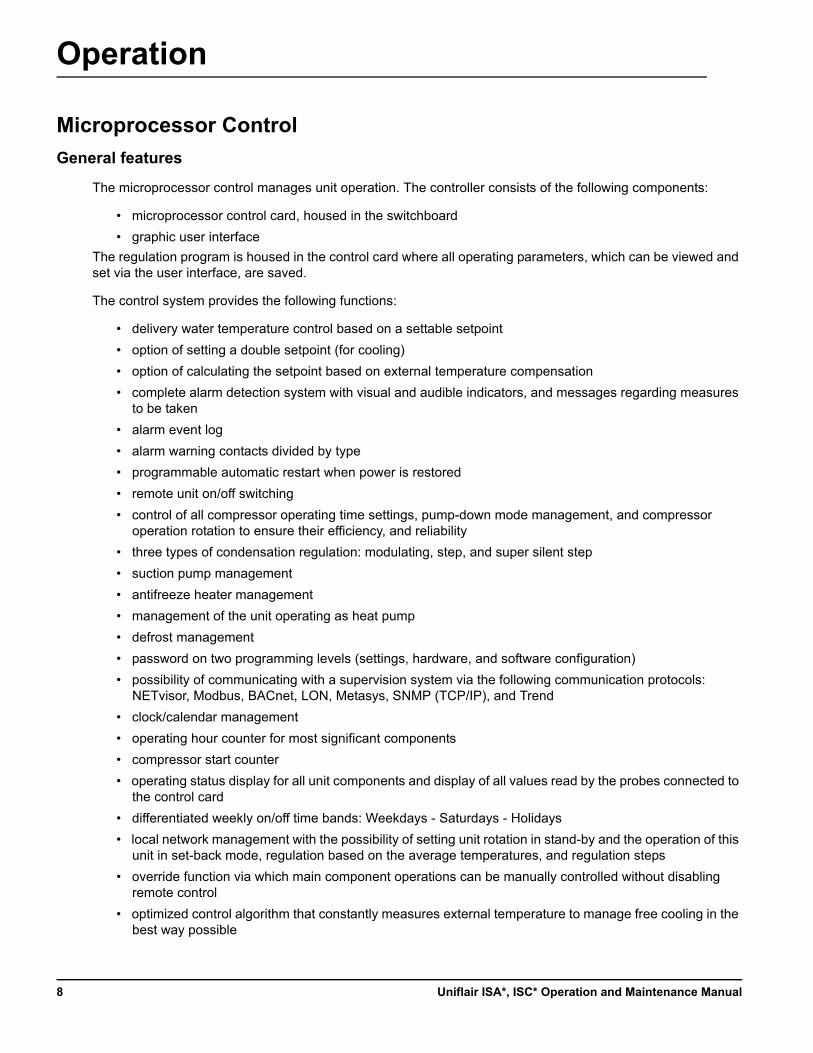
General features
The microprocessor control manages unit operation. The controller consists of the following components:
• microprocessor control card, housed in the switchboard
• graphic user interface
The regulation program is housed in the control card where all operating parameters, which can be viewed and set via the user interface, are saved.
The control system provides the following functions:
• delivery water temperature control based on a settable setpoint
• option of setting a double setpoint (for cooling)
• option of calculating the setpoint based on external temperature compensation
• complete alarm detection system with visual and audible indicators, and messages regarding measures to be taken
• alarm event log
• alarm warning contacts divided by type
• programmable automatic restart when power is restored
• remote unit on/off switching
• control of all compressor operating time settings, pump-down mode management, and compressor operation rotation to ensure their efficiency, and reliability
• three types of condensation regulation: modulating, step, and super silent step
• suction pump management
• antifreeze heater management
• management of the unit operating as heat pump
• defrost management
• password on two programming levels (settings, hardware, and software configuration)
• possibility of communicating with a supervision system via the following communication protocols: NETvisor, Modbus, BACnet, LON, Metasys, SNMP (TCP/IP), and Trend
• clock/calendar management
• operating hour counter for most significant components
• compressor start counter
• operating status display for all unit components and display of all values read by the probes connected to the control card
• differentiated weekly on/off time bands: Weekdays - Saturdays - Holidays
• local network management with the possibility of setting unit rotation in stand-by and the operation of this unit in set-back mode, regulation based on the average temperatures, and regulation steps
• override function via which main component operations can be manually controlled without disabling remote control
• optimized control algorithm that constantly measures external temperature to manage free cooling in the best way possible
Uniflair ISA*, ISC* Operation and Maintenance Manual8
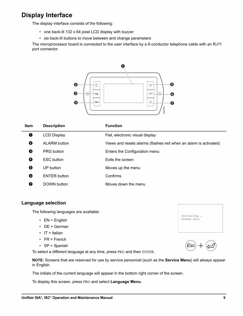
Display InterfaceThe display interface consists of the following:
• one back-lit 132 x 64 pixel LCD display with buzzer
• six back-lit buttons to move between and change parameters
The microprocessor board is connected to the user interface by a 6-conductor telephone cable with an RJ11 port connector.
Language selection
The following languages are available:
• EN = English
• DE = German
• IT = Italian
• FR = French
• SP = Spanish
To select a different language at any time, press PRG and then ENTER.
NOTE: Screens that are reserved for use by service personnel (such as the Service Menu) will always appear in English.
The initials of the current language will appear in the bottom right corner of the screen.
To display this screen, press PRG and select Language Menu.
Item Description Function
LCD Display Flat, electronic visual display
ALARM button Views and resets alarms (flashes red when an alarm is activated)
PRG button Enters the Configuration menu
ESC button Exits the screen
UP button Moves up the menu
ENTER button Confirms
DOWN button Moves down the menu
na36
36a
Initiating...Please wait
Esc
9Uniflair ISA*, ISC* Operation and Maintenance Manual
Program identification
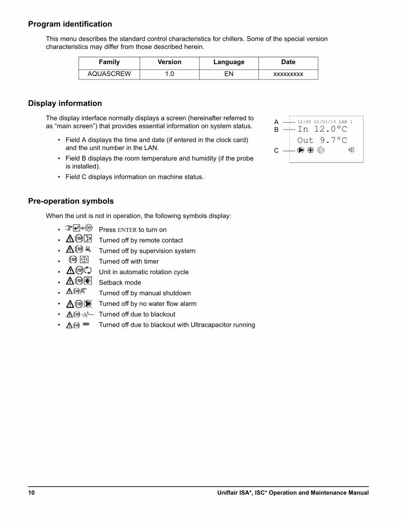
This menu describes the standard control characteristics for chillers. Some of the special version characteristics may differ from those described herein.
Display information
The display interface normally displays a screen (hereinafter referred to as “main screen”) that provides essential information on system status.
• Field A displays the time and date (if entered in the clock card) and the unit number in the LAN.
• Field B displays the room temperature and humidity (if the probe is installed).
• Field C displays information on machine status.
Pre-operation symbols
When the unit is not in operation, the following symbols display:
• Press ENTER to turn on
• Turned off by remote contact
• Turned off by supervision system
• Turned off with timer
• Unit in automatic rotation cycle
• Setback mode
• Turned off by manual shutdown
• Turned off by no water flow alarm
• Turned off due to blackout
• Turned off due to blackout with Ultracapacitor running
Family Version Language Date
AQUASCREW 1.0 EN xxxxxxxxx
12:00 01/01/15 LAN 1
In 12.0ºCOut 9.7ºC
AB
C
Uniflair ISA*, ISC* Operation and Maintenance Manual10
Operation symbols
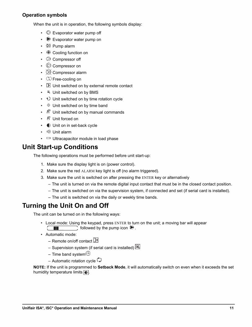
When the unit is in operation, the following symbols display:
• Evaporator water pump off
• Evaporator water pump on
• Pump alarm
• Cooling function on
• Compressor off
• Compressor on
• Compressor alarm
• Free-cooling on
• Unit switched on by external remote contact
• Unit switched on by BMS
• Unit switched on by time rotation cycle
• Unit switched on by time band
• Unit switched on by manual commands
• Unit forced on
• Unit on in set-back cycle
• Unit alarm
• Ultracapacitor module in load phase
Unit Start-up ConditionsThe following operations must be performed before unit start-up:
1. Make sure the display light is on (power control).
2. Make sure the red ALARM key light is off (no alarm triggered).
3. Make sure the unit is switched on after pressing the ENTER key or alternatively
– The unit is turned on via the remote digital input contact that must be in the closed contact position.
– The unit is switched on via the supervision system, if connected and set (if serial card is installed).
– The unit is switched on via the daily or weekly time bands.
Turning the Unit On and OffThe unit can be turned on in the following ways:
• Local mode: Using the keypad, press ENTER to turn on the unit; a moving bar will appear followed by the pump icon .
• Automatic mode:
– Remote on/off contact
– Supervision system (if serial card is installed)
– Time band system
– Automatic rotation cycle
NOTE: If the unit is programmed to Setback Mode, it will automatically switch on even when it exceeds the set humidity temperature limits .
11Uniflair ISA*, ISC* Operation and Maintenance Manual
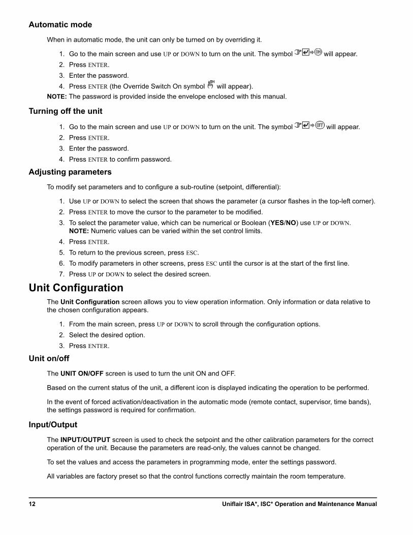
Automatic mode
When in automatic mode, the unit can only be turned on by overriding it.
1. Go to the main screen and use UP or DOWN to turn on the unit. The symbol will appear.
2. Press ENTER.
3. Enter the password.
4. Press ENTER (the Override Switch On symbol will appear).
NOTE: The password is provided inside the envelope enclosed with this manual.
Turning off the unit
1. Go to the main screen and use UP or DOWN to turn on the unit. The symbol will appear.
2. Press ENTER.
3. Enter the password.
4. Press ENTER to confirm password.
Adjusting parameters
To modify set parameters and to configure a sub-routine (setpoint, differential):
1. Use UP or DOWN to select the screen that shows the parameter (a cursor flashes in the top-left corner).
2. Press ENTER to move the cursor to the parameter to be modified.
3. To select the parameter value, which can be numerical or Boolean (YES/NO) use UP or DOWN.NOTE: Numeric values can be varied within the set control limits.
4. Press ENTER.
5. To return to the previous screen, press ESC.
6. To modify parameters in other screens, press ESC until the cursor is at the start of the first line.
7. Press UP or DOWN to select the desired screen.
Unit ConfigurationThe Unit Configuration screen allows you to view operation information. Only information or data relative to the chosen configuration appears.
1. From the main screen, press UP or DOWN to scroll through the configuration options.
2. Select the desired option.
3. Press ENTER.
Unit on/off
The UNIT ON/OFF screen is used to turn the unit ON and OFF.
Based on the current status of the unit, a different icon is displayed indicating the operation to be performed.
In the event of forced activation/deactivation in the automatic mode (remote contact, supervisor, time bands), the settings password is required for confirmation.
Input/Output
The INPUT/OUTPUT screen is used to check the setpoint and the other calibration parameters for the correct operation of the unit. Because the parameters are read-only, the values cannot be changed.
To set the values and access the parameters in programming mode, enter the settings password.
All variables are factory preset so that the control functions correctly maintain the room temperature.
Uniflair ISA*, ISC* Operation and Maintenance Manual12
Setpoint remote
The SETPOINT REMOTE screen is used to check the percent offset sent from the OMI device on the unit with LAN 1 address.
• Signal From OMI x.x%: Signal transmitted by OMI to LAN 1 unit
• Offset xx.x°C: Offset in degrees centigrade, calculated based on the signal sent by OMI and MAX Offset parameter
• Watchdog: Signal that OMI sends to the LAN 1 unit only to check for serial communications
Alarms history
The ALARMS HISTORY screen displays the historical sequence of the alarms activated (the microprocessor stores the last 200 events in its memory).
All the alarms saved can be read in sequence by pressing UP or DOWN. The date and time are recorded for each alarm event.
Software information
The SOFTWARE INFORMATION screen displays the software version, BIOS, boot, and unit serial number.
This information is essential when adding a new unit to a group of connected units in the LAN (the controllers must have the same program version).
When contacting customer support, the version of the control program saved on the control board must be indicated exactly.
pLan network status
The pLAN NETWORK STATUS screen displays the pLan network status, indicating all terminals and pCO cards connected on the same network.
13Uniflair ISA*, ISC* Operation and Maintenance Manual
Settings MenuThe Settings Menu sets the unit operating and signal parameters. These include the following settings:
• Operational Settings
• Hour Meter Settings
• Clock
NOTE: This menu describes the functions of the program in general and, based on the configuration set, the fields and configuration screens may be enabled or disabled.
1. Press PRG.
2. Select Settings Menu.
3. Press ENTER.
4. Enter the calibration password by pressing UP or DOWN.
5. Press ENTER.
Operative settings
All variables are preset in the factory so control functions correctly maintain standard conditions in the room.
This screen displays the delivery water temperature setpoint the unit is using as a reference for regulation. The following row displays a message that indicates the origin of the setpoint if different from the factory standard:
• Optional Set Point: This indicates that the second setpoint is active due to the contact switch at digital input set as second setpoint.
• Watch SetP.: This indicates that the set-back cycle setpoint is active.
Cooling setpoint: This screen sets the standard cooling setpoint and any “optional second setpoint” enabled by external consent that can be either digital or via BMS.
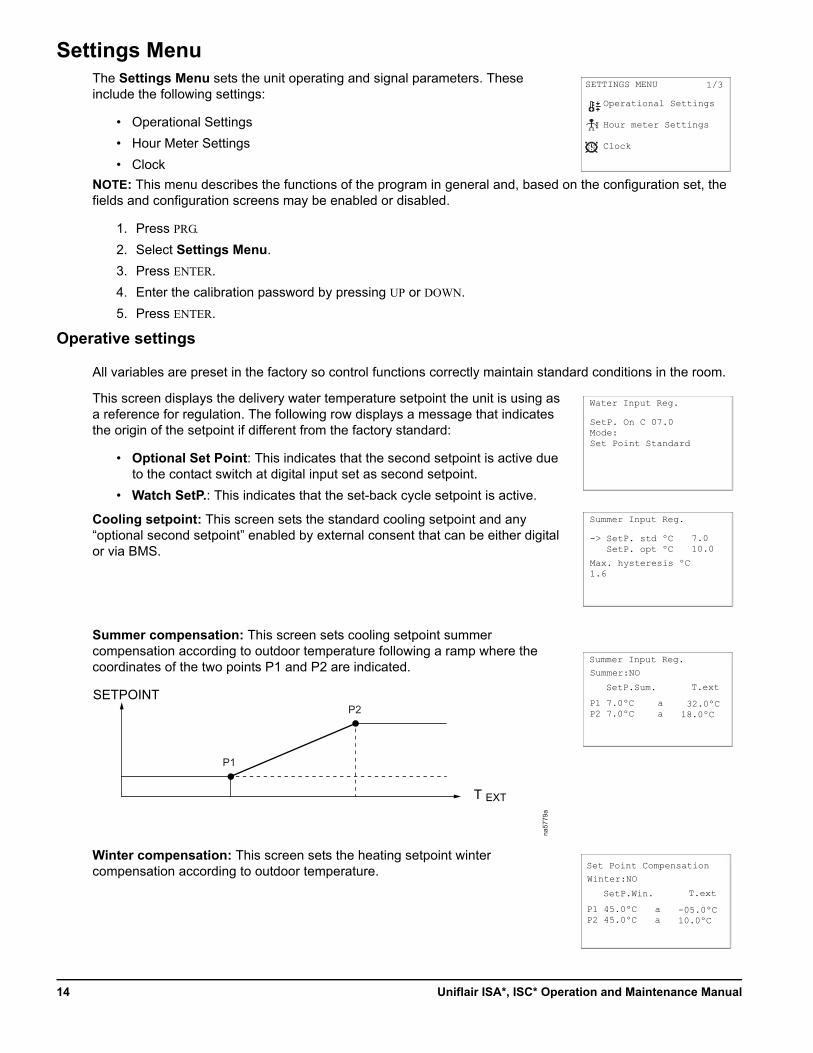
Summer compensation: This screen sets cooling setpoint summer compensation according to outdoor temperature following a ramp where the coordinates of the two points P1 and P2 are indicated.
Winter compensation: This screen sets the heating setpoint winter compensation according to outdoor temperature.
SETTINGS MENU
Operational Settings
Hour meter Settings
Clock
1/3
Water Input Reg.
SetP. On C 07.0Mode:Set Point Standard
Summer Input Reg.
SetP. std ºC SetP. opt ºC
Max. hysteresis ºC1.6
-> 7.010.0
Summer Input Reg.
SetP.Sum.
P1 7.0ºCP2 7.0ºC
T.ext
Summer:NO
aa
32.0ºC18.0ºC
P1
P2
na57
79a
SETPOINT
T EXT
Set Point Compensation
SetP.Win.
P1 45.0ºCP2 45.0ºC
T.ext
Winter:NO
aa
-05.0ºC10.0ºC
Uniflair ISA*, ISC* Operation and Maintenance Manual14
Alarm thresholds: This screen sets alarm thresholds for water delivery temperature in summer.
Set-back cycle
The set-back cycle, enabled or disabled via keyboard, automatically restarts the stopped, but still powered, unit based on a setpoint for this operating mode. The set-back cycle checks environmental conditions, even when the system is off. Its operations are not influenced by signals coming from any remote control systems, which take priority. The unit starting due to a set-back cycle is not considered an alarm condition.
This screen sets set-back cycle operating mode start and the operating setpoint during the set-back cycle.
This screen sets water circulation pump operations during a set-back cycle for 120 seconds. If set to YES, the pump turns on cyclically based on the set time interval.
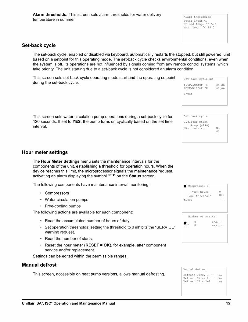
Hour meter settings
The Hour Meter Settings menu sets the maintenance intervals for the components of the unit, establishing a threshold for operation hours. When the device reaches this limit, the microprocessor signals the maintenance request, activating an alarm displaying the symbol “ ” on the Status screen.
The following components have maintenance interval monitoring:
• Compressors
• Water circulation pumps
• Free-cooling pumps
The following actions are available for each component:
• Read the accumulated number of hours of duty.
• Set operation thresholds; setting the threshold to 0 inhibits the “SERVICE” warning request.
• Read the number of starts.
• Reset the hour meter (RESET = OK), for example, after component service and/or replacement.
Settings can be edited within the permissible ranges.
Manual defrost
This screen, accessible on heat pump versions, allows manual defrosting.
Alarm thresholds
Water input T.Unload Temp. ºC 5.0Max. Temp. ºC 18.0
Set-back cycle NO
SetP.Summer ºCSetP.Winter ºC
Set-back cycle
00.0000.00
Input
Cyclical start
Min. interval No00
Pump (s120)
Compressor 1
Work hours
C.1C.2
Hour thresholdReset
0000
--
Number of starts
00
res. --res. --
Defrost Circ. 1 --Defrost Circ. 2 --Defrost Circ.1-2
NoNoNo
Manual defrost
15Uniflair ISA*, ISC* Operation and Maintenance Manual
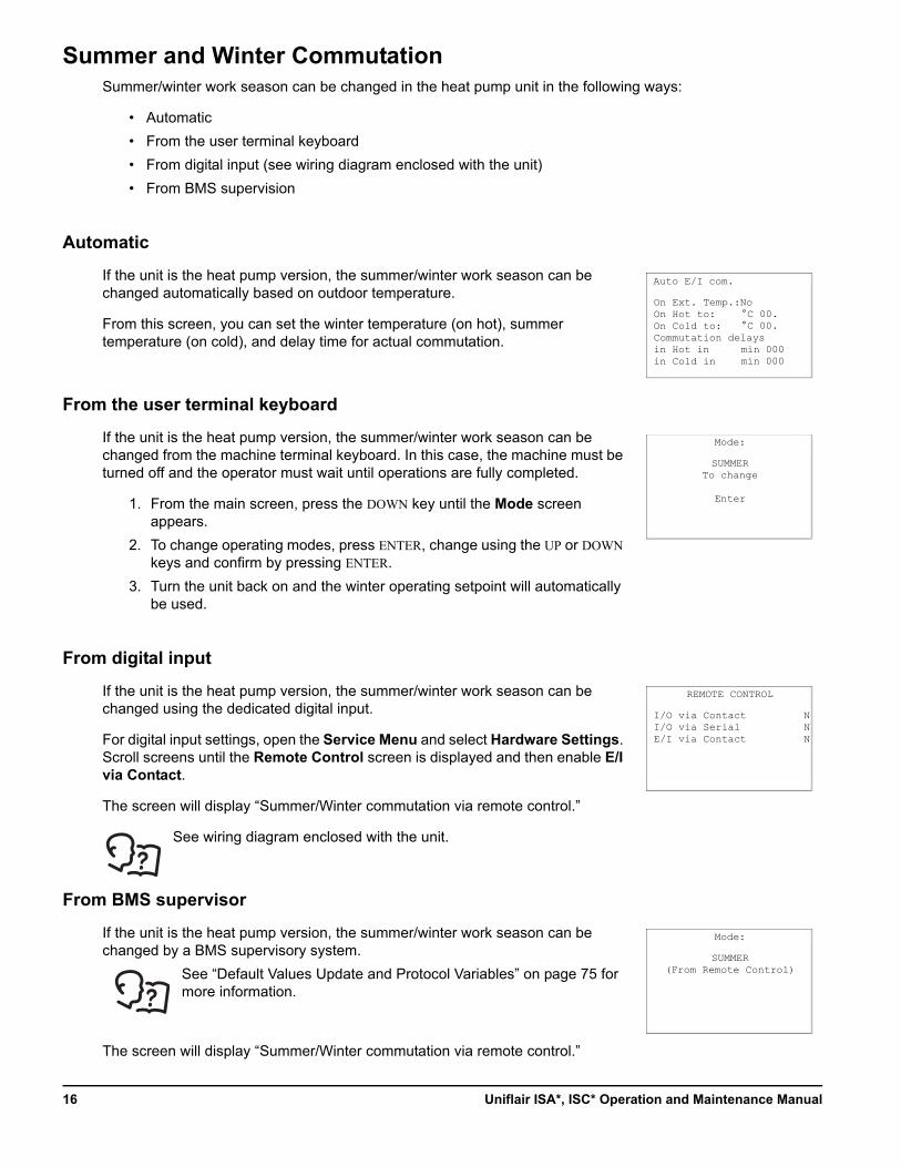
Summer and Winter CommutationSummer/winter work season can be changed in the heat pump unit in the following ways:
• Automatic
• From the user terminal keyboard
• From digital input (see wiring diagram enclosed with the unit)
• From BMS supervision
Automatic
If the unit is the heat pump version, the summer/winter work season can be changed automatically based on outdoor temperature.
From this screen, you can set the winter temperature (on hot), summer temperature (on cold), and delay time for actual commutation.
From the user terminal keyboard
If the unit is the heat pump version, the summer/winter work season can be changed from the machine terminal keyboard. In this case, the machine must be turned off and the operator must wait until operations are fully completed.
1. From the main screen, press the DOWN key until the Mode screen appears.
2. To change operating modes, press ENTER, change using the UP or DOWN keys and confirm by pressing ENTER.
3. Turn the unit back on and the winter operating setpoint will automatically be used.
From digital input
If the unit is the heat pump version, the summer/winter work season can be changed using the dedicated digital input.
For digital input settings, open the Service Menu and select Hardware Settings. Scroll screens until the Remote Control screen is displayed and then enable E/I via Contact.
The screen will display “Summer/Winter commutation via remote control.”
See wiring diagram enclosed with the unit.
From BMS supervisor
If the unit is the heat pump version, the summer/winter work season can be changed by a BMS supervisory system.
The screen will display “Summer/Winter commutation via remote control.”
Auto E/I com.
On Ext. Temp.:NoOn Hot to:On Cold to: Commutation delaysin Hot inin Cold in
°C 00.°C 00.
min 000min 000
Mode:
SUMMERTo change
Enter
REMOTE CONTROL
I/O via ContactI/O via SerialE/I via Contact
NNN
Mode:
SUMMER(From Remote Control)See “Default Values Update and Protocol Variables” on page 75 for
more information.
Uniflair ISA*, ISC* Operation and Maintenance Manual16
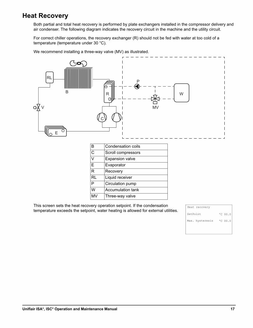
Heat RecoveryBoth partial and total heat recovery is performed by plate exchangers installed in the compressor delivery and air condenser. The following diagram indicates the recovery circuit in the machine and the utility circuit.
For correct chiller operations, the recovery exchanger (R) should not be fed with water at too cold of a temperature (temperature under 30 °C).
We recommend installing a three-way valve (MV) as illustrated.
This screen sets the heat recovery operation setpoint. If the condensation temperature exceeds the setpoint, water heating is allowed for external utilities.
B Condensation coils
C Scroll compressors
V Expansion valve
E Evaporator
R Recovery
RL Liquid receiver
P Circulation pump
W Accumulation tank
MV Three-way valve
W
MV
P
R
C
B
E
V
RL
Heat recovery
SetPoint
Max. hysteresis
ºC 00.0
ºC 00.0
17Uniflair ISA*, ISC* Operation and Maintenance Manual
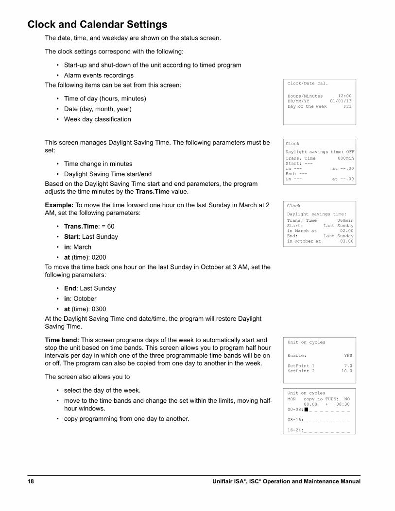
Clock and Calendar SettingsThe date, time, and weekday are shown on the status screen.
The clock settings correspond with the following:
• Start-up and shut-down of the unit according to timed program
• Alarm events recordings
The following items can be set from this screen:
• Time of day (hours, minutes)
• Date (day, month, year)
• Week day classification
This screen manages Daylight Saving Time. The following parameters must be set:
• Time change in minutes
• Daylight Saving Time start/end
Based on the Daylight Saving Time start and end parameters, the program adjusts the time minutes by the Trans.Time value.
Example: To move the time forward one hour on the last Sunday in March at 2 AM, set the following parameters:
• Trans.Time: = 60
• Start: Last Sunday
• in: March
• at (time): 0200
To move the time back one hour on the last Sunday in October at 3 AM, set the following parameters:
• End: Last Sunday
• in: October
• at (time): 0300
At the Daylight Saving Time end date/time, the program will restore Daylight Saving Time.
Time band: This screen programs days of the week to automatically start and stop the unit based on time bands. This screen allows you to program half hour intervals per day in which one of the three programmable time bands will be on or off. The program can also be copied from one day to another in the week.
The screen also allows you to
• select the day of the week.
• move to the time bands and change the set within the limits, moving half-hour windows.
• copy programming from one day to another.
Trans. TimeStart: ---in ---End: ---in ---
Hours/MinutesDD/MM/YYDay of the week
Clock/Date cal.
Clock
Unit on cycles
12:0001/01/13
Fri
000min
at --.00
at --.00
Daylight savings time: OFF
Trans. TimeStart: in March atEnd: in October at
Clock
060minLast Sunday
02.00Last Sunday
03.00
Daylight savings time:
MON copy to TUES: NO 00.00 + 00:3000-08: _ _ _ _ _ _ _ _
08-16:_ _ _ _ _ _ _ _ _
16-24:_ _ _ _ _ _ _ _ _
Enable:
SetPoint 1SetPoint 2
Unit on cycles
YES
7.010.0
Uniflair ISA*, ISC* Operation and Maintenance Manual18
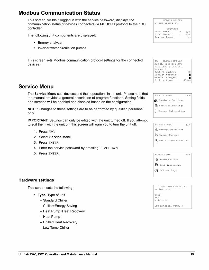
Modbus Communication StatusThis screen, visible if logged in with the service password, displays the communication status of devices connected via MODBUS protocol to the pCO controller.
The following unit components are displayed:
• Energy analyzer
• Inverter water circulation pumps
This screen sets Modbus communication protocol settings for the connected devices.
Service MenuThe Service Menu sets devices and their operations in the unit. Please note that the manual provides a general description of program functions. Setting fields and screens will be enabled and disabled based on the configuration.
NOTE: Changes to these settings are to be performed by qualified personnel only.
IMPORTANT: Settings can only be edited with the unit turned off. If you attempt to edit them with the unit on, this screen will warn you to turn the unit off.
1. Press PRG.
2. Select Service Menu.
3. Press ENTER.
4. Enter the service password by pressing UP or DOWN.
5. Press ENTER.
Hardware settings
This screen sets the following:
• Type: Type of unit
– Standard Chiller
– Chiller+Energy Saving
– Heat Pump+Heat Recovery
– Heat Pump
– Chiller+Heat Recovery
– Low Temp.Chiller
MODBUS MASTERMODBUS MASTER Nº1
CountersTotal.Mess.:Total.Mess.:Counter Reset:
MODBUS MASTERMOD_MB_Protocol_MNGVersion:2.3 04/11/10Master 1Sublist number:Sublist trigger:General trigger:Polling time:
n 000n 000
--
NO
00
000ms
SERVICE MENU
Hardware Settings
Software Settings
Sensor Calibration
1/9
SERVICE MENU
Memory Operations
Manual Control
Serial Communication
4/9
SERVICE MENU
Alarm Address
Unit Interconn.
EXV Settings
7/9
UNIT CONFIGURATIONSeries: ***
Type:***Model:***
Low External Temp. N
19Uniflair ISA*, ISC* Operation and Maintenance Manual
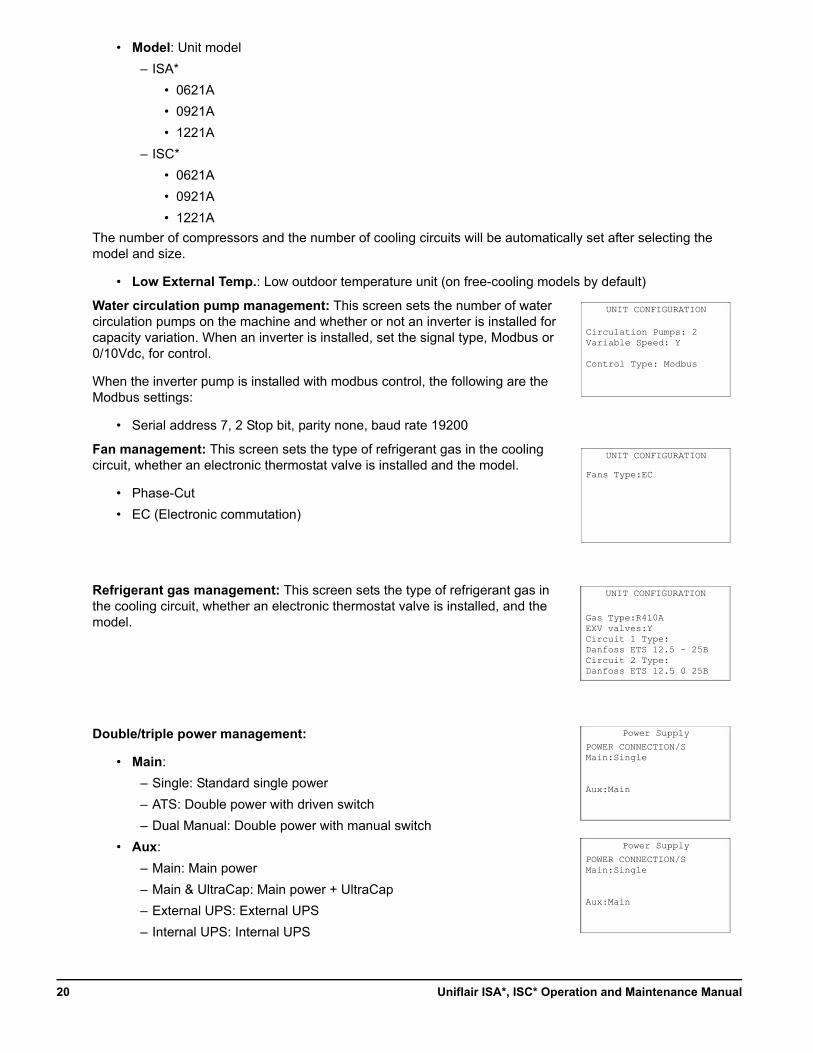
• Model: Unit model
– ISA*
• 0621A
• 0921A
• 1221A
– ISC*
• 0621A
• 0921A
• 1221A
The number of compressors and the number of cooling circuits will be automatically set after selecting the model and size.
• Low External Temp.: Low outdoor temperature unit (on free-cooling models by default)
Water circulation pump management: This screen sets the number of water circulation pumps on the machine and whether or not an inverter is installed for capacity variation. When an inverter is installed, set the signal type, Modbus or 0/10Vdc, for control.
When the inverter pump is installed with modbus control, the following are the Modbus settings:
• Serial address 7, 2 Stop bit, parity none, baud rate 19200
Fan management: This screen sets the type of refrigerant gas in the cooling circuit, whether an electronic thermostat valve is installed and the model.
• Phase-Cut
• EC (Electronic commutation)
Refrigerant gas management: This screen sets the type of refrigerant gas in the cooling circuit, whether an electronic thermostat valve is installed, and the model.
Double/triple power management:
• Main:
– Single: Standard single power
– ATS: Double power with driven switch
– Dual Manual: Double power with manual switch
• Aux:
– Main: Main power
– Main & UltraCap: Main power + UltraCap
– External UPS: External UPS
– Internal UPS: Internal UPS
UNIT CONFIGURATION
Circulation Pumps: 2Variable Speed: Y
Control Type: Modbus
UNIT CONFIGURATION
Fans Type:EC
UNIT CONFIGURATION
Gas Type:R410AEXV valves:YCircuit 1 Type:Danfoss ETS 12.5 - 25BCircuit 2 Type:Danfoss ETS 12.5 0 25B
Power Supply
POWER CONNECTION/SMain:Single
Aux:Main
Power Supply
POWER CONNECTION/SMain:Single
Aux:Main
Uniflair ISA*, ISC* Operation and Maintenance Manual20
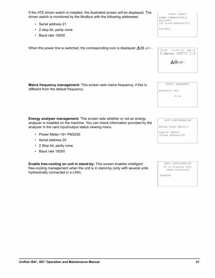
If the ATS driven switch is installed, the illustrated screen will be displayed. The driven switch is monitored by the Modbus with the following addresses:
• Serial address 21
• 2 stop bit, parity none
• Baud rate 19200
When the power line is switched, the corresponding icon is displayed .
Mains frequency management: This screen sets mains frequency, if this is different from the default frequency.
Energy analyzer management: This screen sets whether or not an energy analyzer is installed on the machine. You can check information provided by the analyzer in the card input/output status viewing menu.
• Power Meter:=S= PM3250
• Serial address 20
• 2 Stop bit, parity none
• Baud rate 19200
Enable free-cooling on unit in stand-by: This screen enables intelligent free-cooling management when the unit is in stand-by (only with several units hydraulically connected in a LAN).
Power Supply
POWER CONNECTIONS/SMain:ATS(IG Slave Address:21)
Aux:Main
SUPPLY FREQUENCY
Automatic Set.
50 Hz
12:00 01/01/15 LAN 01
T.Water OUTºC 7.0
UNIT CONFIGURATION
Energy Power Meter:Y
Type=S= PM3250(Slave Address:20)
FC on Stand-by Unit(Hydr.Connected)
Enabled
UNIT CONFIGURATION
21Uniflair ISA*, ISC* Operation and Maintenance Manual
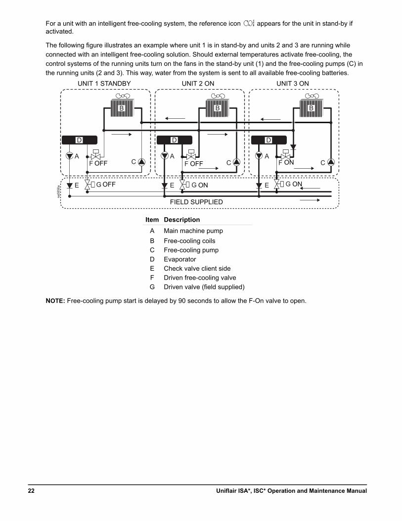
For a unit with an intelligent free-cooling system, the reference icon appears for the unit in stand-by if activated.
The following figure illustrates an example where unit 1 is in stand-by and units 2 and 3 are running while
connected with an intelligent free-cooling solution. Should external temperatures activate free-cooling, the
control systems of the running units turn on the fans in the stand-by unit (1) and the free-cooling pumps (C) in
the running units (2 and 3). This way, water from the system is sent to all available free-cooling batteries.
NOTE: Free-cooling pump start is delayed by 90 seconds to allow the F-On valve to open.
Item Description
A Main machine pump
B Free-cooling coils
C Free-cooling pump
D Evaporator
E Check valve client side
F Driven free-cooling valve
G Driven valve (field supplied)
na58
56a
A
B
D D D
B B
CCC
E
A
E
A
EG
F
G
F
G
F
UNIT 1 STANDBY UNIT 2 ON UNIT 3 ON
OFF ON
ONOFFOFF
ON
FIELD SUPPLIED
Uniflair ISA*, ISC* Operation and Maintenance Manual22
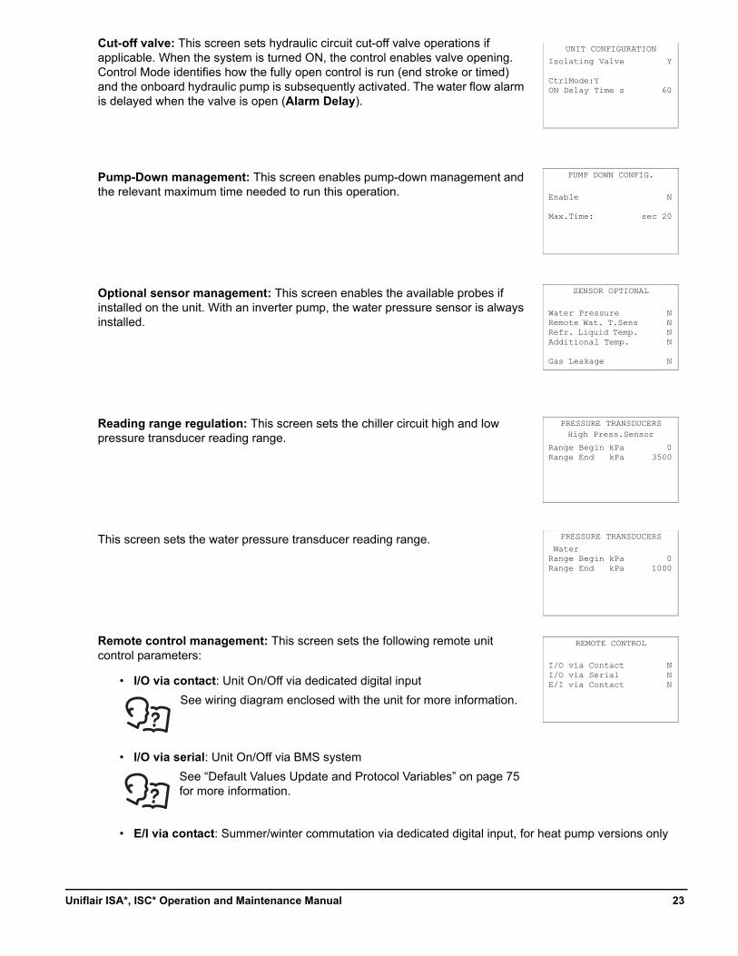
Cut-off valve: This screen sets hydraulic circuit cut-off valve operations if applicable. When the system is turned ON, the control enables valve opening. Control Mode identifies how the fully open control is run (end stroke or timed) and the onboard hydraulic pump is subsequently activated. The water flow alarm is delayed when the valve is open (Alarm Delay).
Pump-Down management: This screen enables pump-down management and the relevant maximum time needed to run this operation.
Optional sensor management: This screen enables the available probes if installed on the unit. With an inverter pump, the water pressure sensor is always installed.
Reading range regulation: This screen sets the chiller circuit high and low pressure transducer reading range.
This screen sets the water pressure transducer reading range.
Remote control management: This screen sets the following remote unit control parameters:
• I/O via contact: Unit On/Off via dedicated digital input
• I/O via serial: Unit On/Off via BMS system
• E/I via contact: Summer/winter commutation via dedicated digital input, for heat pump versions only
UNIT CONFIGURATION
Isolating Valve
CtrlMode:YON Delay Time s
Y
60
PUMP DOWN CONFIG.
Enable
Max.Time:
N
sec 20
SENSOR OPTIONAL
Water PressureRemote Wat. T.SensRefr. Liquid Temp.Additional Temp.
Gas Leakage
NNNN
N
PRESSURE TRANSDUCERS
Range Begin kPaRange End kPa
03500
PRESSURE TRANSDUCERS
WaterRange Begin kPaRange End kPa
01000
REMOTE CONTROL
I/O via ContactI/O via SerialE/I via Contact
NNN
High Press.Sensor
See wiring diagram enclosed with the unit for more information.
See “Default Values Update and Protocol Variables” on page 75 for more information.
23Uniflair ISA*, ISC* Operation and Maintenance Manual
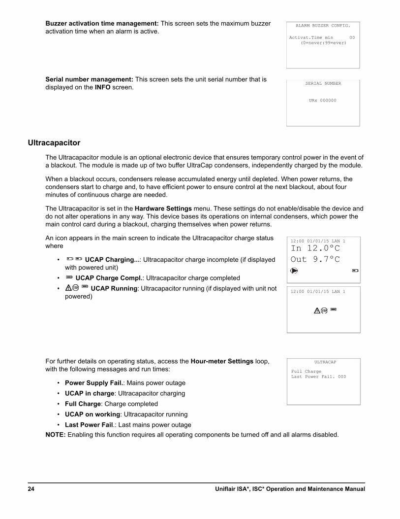
Buzzer activation time management: This screen sets the maximum buzzer activation time when an alarm is active.
Serial number management: This screen sets the unit serial number that is displayed on the INFO screen.
Ultracapacitor
The Ultracapacitor module is an optional electronic device that ensures temporary control power in the event of a blackout. The module is made up of two buffer UltraCap condensers, independently charged by the module.
When a blackout occurs, condensers release accumulated energy until depleted. When power returns, the condensers start to charge and, to have efficient power to ensure control at the next blackout, about four minutes of continuous charge are needed.
The Ultracapacitor is set in the Hardware Settings menu. These settings do not enable/disable the device and do not alter operations in any way. This device bases its operations on internal condensers, which power the main control card during a blackout, charging themselves when power returns.
An icon appears in the main screen to indicate the Ultracapacitor charge status where
• UCAP Charging...: Ultracapacitor charge incomplete (if displayed with powered unit)
• UCAP Charge Compl.: Ultracapacitor charge completed
• UCAP Running: Ultracapacitor running (if displayed with unit not powered)
For further details on operating status, access the Hour-meter Settings loop, with the following messages and run times:
• Power Supply Fail.: Mains power outage
• UCAP in charge: Ultracapacitor charging
• Full Charge: Charge completed
• UCAP on working: Ultracapacitor running
• Last Power Fail.: Last mains power outage
NOTE: Enabling this function requires all operating components be turned off and all alarms disabled.
ALARM BUZZER CONFIG.
Activat.Time min (0=never:99=ever)
00
URx 000000
SERIAL NUMBER
ULTRACAP
Full ChargeLast Power Fail. 000
12:00 01/01/15 LAN 1
In 12.0ºCOut 9.7ºC
12:00 01/01/15 LAN 1
Uniflair ISA*, ISC* Operation and Maintenance Manual24
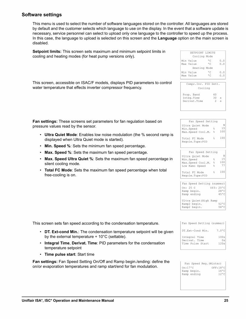
Software settings
This menu is used to select the number of software languages stored on the controller. All languages are stored by default and the customer selects which language to use on the display. In the event that a software update is necessary, service personnel can select to upload only one language to the controller to speed up the process. In this case, the language to upload is selected on this screen and the Language option on the main screen is disabled.
Setpoint limits: This screen sets maximum and minimum setpoint limits in cooling and heating modes (for heat pump versions only).
This screen, accessible on ISAC/F models, displays PID parameters to control water temperature that effects inverter compressor frequency.
Fan settings: These screens set parameters for fan regulation based on pressure values read by the sensor.
• Ultra Quiet Mode: Enables low noise modulation (the % second ramp is displayed when Ultra Quiet mode is started).
• Min. Speed %: Sets the minimum fan speed percentage.
• Max. Speed %: Sets the maximum fan speed percentage.
• Max. Speed Ultra Quiet %: Sets the maximum fan speed percentage in silent cooling mode.
• Total FC Mode: Sets the maximum fan speed percentage when total free-cooling is on.
This screen sets fan speed according to the condensation temperature.
• DT. Ext-cond Min.: The condensation temperature setpoint will be given by the external temperature + 10°C (settable).
• Integral Time, Derivat. Time: PID parameters for the condensation temperature setpoint
• Time pulse start: Start time
Fan settings: Fan Speed Setting On/Off and Ramp begin./ending: define the on/or evaporation temperatures and ramp start/end for fan modulation.
SETPOINT LIMITS
Min ValueMax Value
0.00.0
Cooling Mode
Min ValueMax Value
0.00.0
Heating Mode
ºCºC
ºCºC
Fan Speed Setting
Ultra Quiet ModeMin.SpeedMax.Speed Cool.M.
Total FC ModeRegole.Tupe:PID
Fan Speed Setting (summer)
On: 25 CRamp begin.Ramp ending
Ultra Quiet(High RampRamp2 begin.Ramp2 begin.
Off: 20ºC28ºC45ºC
52ºC58ºC
Fan Speed Setting (summer)
DT.Ext-Cond Min.
Integral TimeDerivat. TimeTime Pulse Start
7.0ºC
100s0s
120s
%%
%
N15
100
100
Fan Speed Setting
Ultra Quiet ModeMin.SpeedMax.Speed Cool.M.Low Ramo Speed
Total FC ModeRegole.Tupe:PID
%%%
%
N15
10077
100
Compr.Inv. PID Sett.
Cooling
Prop. Band 40Integ.Time 30 sDerivat.Time 2 s
Fan Speed Reg.(Winter)
On:17ºCRamp begin.Ramp ending
OFF:18ºC16ºC12ºC
25Uniflair ISA*, ISC* Operation and Maintenance Manual
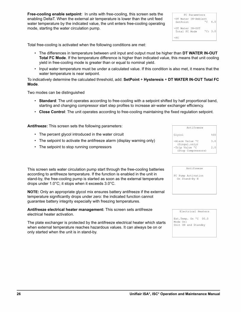
Free-cooling enable setpoint: In units with free-cooling, this screen sets the enabling DeltaT. When the external air temperature is lower than the unit feed water temperature by the indicated value, the unit enters free-cooling operating mode, starting the water circulation pump.
Total free-cooling is activated when the following conditions are met:
• The differences in temperature between unit input and output must be higher than DT WATER IN-OUT Total FC Mode. If the temperature difference is higher than indicated value, this means that unit cooling yield in free-cooling mode is greater than or equal to nominal yield.
• Input water temperature must be under a calculated value. If this condition is also met, it means that the water temperature is near setpoint.
To indicatively determine the calculated threshold, add: SetPoint + Hysteresis + DT WATER IN-OUT Total FC Mode.
Two modes can be distinguished
• Standard: The unit operates according to free-cooling with a setpoint shifted by half proportional band, starting and changing compressor start step profiles to increase air-water exchanger efficiency.
• Close Control: The unit operates according to free-cooling maintaining the fixed regulation setpoint.
Antifreeze: This screen sets the following parameters:
• The percent glycol introduced in the water circuit
• The setpoint to activate the antifreeze alarm (display warning only)
• The setpoint to stop running compressors
This screen sets water circulation pump start through the free-cooling batteries according to antifreeze temperature. If the function is enabled in the unit in stand-by, the free-cooling pump is started as soon as the external temperature drops under 1.0°C; it stops when it exceeds 3.0°C.
NOTE: Only an appropriate glycol mix ensures battery antifreeze if the external temperature significantly drops under zero: the indicated function cannot guarantee battery integrity especially with freezing temperatures.
Antifreeze electrical heater management: This screen sets antifreeze electrical heater activation.
The plate exchanger is protected by the antifreeze electrical heater which starts when external temperature reaches hazardous values. It can always be on or only started when the unit is in stand-by.
FC Parameters
ºC 4.0
ºC: 3.0
-DT Water IN-Ambient SetPoint
-DT Water IN-OUT Total FC Mode
-FC
Antifreeze
Glycol
-Alarm Value ºC (Singal.only)-Trip Value ºC (Stop Compressors)
%00
3.0
2.0
Antifreeze
FC Pump Activation On Stand-By N
Electrical Heaters
Ext.Temp. On ºC 00.0Mode On:Unit ON and Standby
Uniflair ISA*, ISC* Operation and Maintenance Manual26
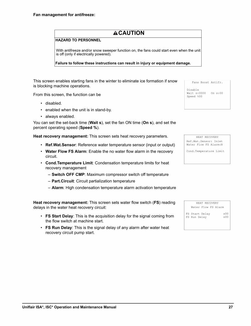
Fan management for antifreeze:
This screen enables starting fans in the winter to eliminate ice formation if snow is blocking machine operations.
From this screen, the function can be
• disabled.
• enabled when the unit is in stand-by.
• always enabled.
You can set the set-back time (Wait s), set the fan ON time (On s), and set the percent operating speed (Speed %).
Heat recovery management: This screen sets heat recovery parameters.
• Ref.Wat.Sensor: Reference water temperature sensor (input or output)
• Water Flow FS Alarm: Enable the no water flow alarm in the recovery circuit.
• Cond.Temperature Limit: Condensation temperature limits for heat recovery management
– Switch OFF CMP: Maximum compressor switch off temperature
– Part.Circuit: Circuit partialization temperature
– Alarm: High condensation temperature alarm activation temperature
Heat recovery management: This screen sets water flow switch (FS) reading delays in the water heat recovery circuit:
• FS Start Delay: This is the acquisition delay for the signal coming from the flow switch at machine start.
• FS Run Delay: This is the signal delay of any alarm after water heat recovery circuit pump start.
CAUTIONHAZARD TO PERSONNEL
With antifreeze and/or snow sweeper function on, the fans could start even when the unit is off (only if electrically powered).
Failure to follow these instructions can result in injury or equipment damage.
HEAT RECOVERY
Ref.Wat.Sensor: InletWater Flow FS Alarm:N
Cond.Temperature Limit
HEAT RECOVERY
Water Flow FS Alarm
FS Start DelayFS Run Delay
Fans Boost Antifr.
DisableWait s:0000 On s:00Speed %00
s00s00
27Uniflair ISA*, ISC* Operation and Maintenance Manual
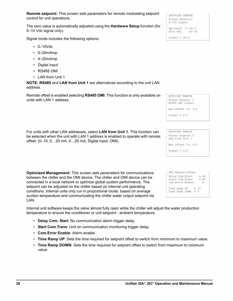
Remote setpoint: This screen sets parameters for remote modulating setpoint control for unit operations.
The zero value is automatically adjusted using the Hardware Setup function (for 0–10 Vdc signal only).
Signal mode includes the following options:
• 0–10Vdc
• 0–20mAmp
• 4–20mAmp
• Digital Input
• RS485 OMI
• LAN from Unit 1
NOTE: RS485 and LAN from Unit 1 are alternatives according to the unit LAN address.
Remote offset is enabled selecting RS485 OMI. This function is only available on units with LAN 1 address.
For units with other LAN addresses, select LAN from Unit 1. This function can be selected when the unit with LAN 1 address is enabled to operate with remote offset: (0–10, 0…20 mA, 4…20 mA, Digital input, OMI).
Optimized Management: This screen sets parameters for communications between the chiller and the OMI device. The chiller and OMI device can be connected in a local network to optimize global system performance. The setpoint can be adjusted on the chiller based on internal unit operating conditions. Internal units only run in proportional mode, based on average suction temperature and communicating the chiller water output setpoint via LAN.
Internal unit software keeps the valve almost fully open while the chiller will adjust the water production temperature to ensure the conditioner or unit setpoint - ambient temperature.
• Delay Com. Start: No communication alarm trigger delay
• Start Com.Trans: Unit on communication monitoring trigger delay
• Com.Error Enable: Alarm enable
• Time Ramp UP: Sets the time required for setpoint offset to switch from minimum to maximum value.
• Time Ramp DOWN: Sets the time required for setpoint offset to switch from maximum to minimum value.
SETPOINT REMOTE
Offset Enable:Y0-10V Signal
Opt.SetP. ºC 00.0Zero Adj. mV 00
Signal % 00.0
SETPOINT REMOTE
OMI Remote Offset
Delay Com.Start s.60Start Com.Trans s.60Com.Error Enable N
Time Ramp UP m 10Time Ramp DOWN m 5
Offset Enable: YRS485 OMI Signal
Max Offset ºC: 5.0
Signal % 0.0
SETPOINT REMOTE
Offset Enable: YLAN From Unit 1
Max Offset ºC: 5.0
Signal % 0.0
Uniflair ISA*, ISC* Operation and Maintenance Manual28
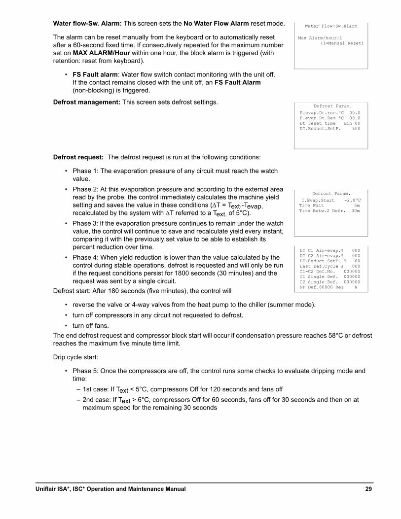
Water flow-Sw. Alarm: This screen sets the No Water Flow Alarm reset mode.
The alarm can be reset manually from the keyboard or to automatically reset after a 60-second fixed time. If consecutively repeated for the maximum number set on MAX ALARM/Hour within one hour, the block alarm is triggered (with retention: reset from keyboard).
• FS Fault alarm: Water flow switch contact monitoring with the unit off.If the contact remains closed with the unit off, an FS Fault Alarm (non-blocking) is triggered.
Defrost management: This screen sets defrost settings.
Defrost request: The defrost request is run at the following conditions:
• Phase 1: The evaporation pressure of any circuit must reach the watch value.
• Phase 2: At this evaporation pressure and according to the external area read by the probe, the control immediately calculates the machine yield setting and saves the value in these conditions (∆T = Text.-Tevap. recalculated by the system with ∆T referred to a Text. of 5°C).
• Phase 3: If the evaporation pressure continues to remain under the watch value, the control will continue to save and recalculate yield every instant, comparing it with the previously set value to be able to establish its percent reduction over time.
• Phase 4: When yield reduction is lower than the value calculated by the control during stable operations, defrost is requested and will only be run if the request conditions persist for 1800 seconds (30 minutes) and the request was sent by a single circuit.
Defrost start: After 180 seconds (five minutes), the control will
• reverse the valve or 4-way valves from the heat pump to the chiller (summer mode).
• turn off compressors in any circuit not requested to defrost.
• turn off fans.
The end defrost request and compressor block start will occur if condensation pressure reaches 58°C or defrost reaches the maximum five minute time limit.
Drip cycle start:
• Phase 5: Once the compressors are off, the control runs some checks to evaluate dripping mode and time:
– 1st case: If Text < 5°C, compressors Off for 120 seconds and fans off
– 2nd case: If Text > 6°C, compressors Off for 60 seconds, fans off for 30 seconds and then on at maximum speed for the remaining 30 seconds
Defrost Param.
P.evap.Dt.rec.ºC 00.0P.evap.Dt.Res.ºC 00.0Dt reset time min 00DT.Reduct.SetP. %00
Defrost Param.
T.Evap.Start -2.0ºC Time Wait 5mTime Betw.2 Defr. 30m
Water Flow-Sw.Alarm
Max Alarm/hour:1 (1=Manual Reset)
DT C1 Air-evap.% 000DT C2 Air-evap.% 000DT.Reduct.SetP. % 00Last Def.Cycle s 000C1-C2 Def.No. 000000C1 Single Def. 000000C2 Single Def. 000000NP Def.00000 Res N
29Uniflair ISA*, ISC* Operation and Maintenance Manual
End defrost and return to normal operations:
• Phase 6: At the end of the drip cycle the control will:
– reverse the valve or 4-way valves from chiller to heat pump (winter mode)
– switch on compressors
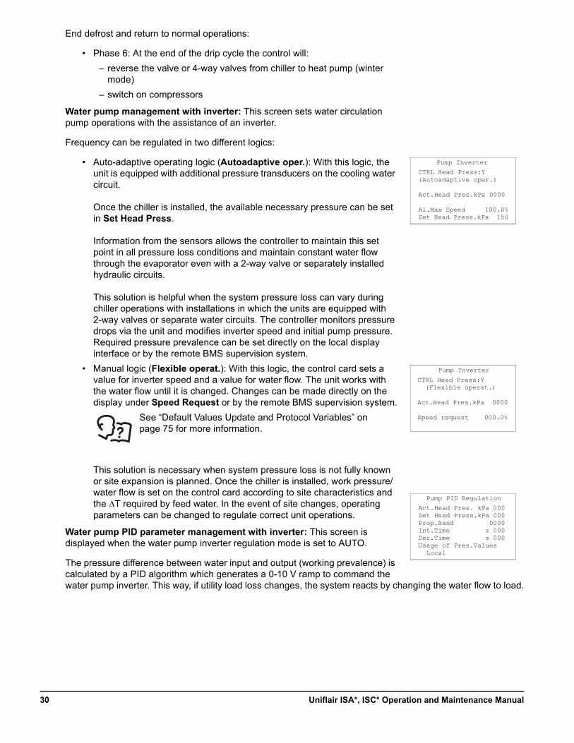
Water pump management with inverter: This screen sets water circulation pump operations with the assistance of an inverter.
Frequency can be regulated in two different logics:
• Auto-adaptive operating logic (Autoadaptive oper.): With this logic, the unit is equipped with additional pressure transducers on the cooling water circuit.
Once the chiller is installed, the available necessary pressure can be set in Set Head Press.
Information from the sensors allows the controller to maintain this set point in all pressure loss conditions and maintain constant water flow through the evaporator even with a 2-way valve or separately installed hydraulic circuits.
This solution is helpful when the system pressure loss can vary during chiller operations with installations in which the units are equipped with 2-way valves or separate water circuits. The controller monitors pressure drops via the unit and modifies inverter speed and initial pump pressure. Required pressure prevalence can be set directly on the local display interface or by the remote BMS supervision system.
• Manual logic (Flexible operat.): With this logic, the control card sets a value for inverter speed and a value for water flow. The unit works with the water flow until it is changed. Changes can be made directly on the display under Speed Request or by the remote BMS supervision system.
This solution is necessary when system pressure loss is not fully known or site expansion is planned. Once the chiller is installed, work pressure/water flow is set on the control card according to site characteristics and the ∆T required by feed water. In the event of site changes, operating parameters can be changed to regulate correct unit operations.
Water pump PID parameter management with inverter: This screen is displayed when the water pump inverter regulation mode is set to AUTO.
The pressure difference between water input and output (working prevalence) is calculated by a PID algorithm which generates a 0-10 V ramp to command the water pump inverter. This way, if utility load loss changes, the system reacts by changing the water flow to load.
Pump Inverter
CTRL Head Press:Y(Autoadaptive oper.)
Act.Head Pres.kPa 0000
Al.Max Speed 100.0%Set Head Press.kPa 150
Pump Inverter
CTRL Head Press:Y (Flexible operat.)
Act.Head Pres.kPa 0000
Speed request 000.0%
Pump PID Regulation
Act.Head Pres. kPa 000Set Head Press.kPa 000Prop.Band 0000Int.Time s 000Der.Time s 000Usage of Pres.Values Local
See “Default Values Update and Protocol Variables” on page 75 for more information.
Uniflair ISA*, ISC* Operation and Maintenance Manual30
This screen sets the following parameters:
• Available prevalence setpoint: calculates the difference between water output and input pressures. When the prevalence (∆P out-in unit) is higher than the required setpoint, the pump reduces water flow.
• Proportional band
• Integral time
• Derivative time
This screen (read only) displays the following inverter settings:
• Minimum and maximum frequency
• Acceleration time
• Deceleration time
IMPORTANT: To avoid system oscillations, we recommend you set high proportional band and integral time values.
Pump operations can also be managed with the measured “average” pressure value or with the “local” value measured by the single probe in the unit:
• Mode: Local: The pump is controlled by the pressure values read by the unit probes.
• Mode: Average: The pump is controlled by the average pressure values read by unit probes connected in the local LAN.
Water pressure alarm management: When the inverter pump is installed, this screen sets the following parameters:
• High water pressure alarm
• Low water pressure alarm
• Maximum pressure read in the hydraulic circuit
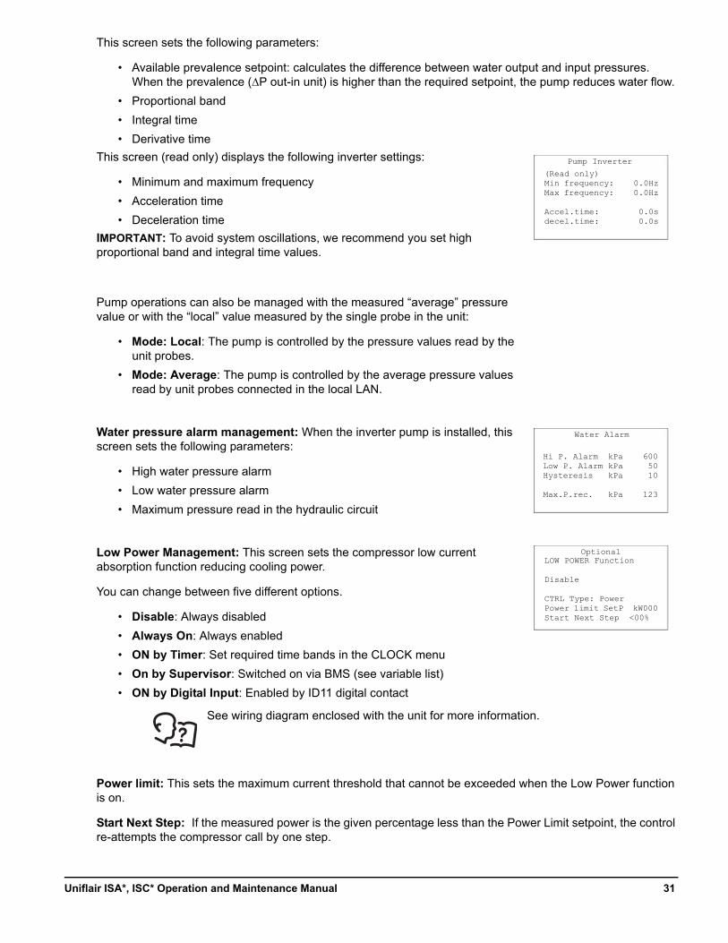
Low Power Management: This screen sets the compressor low current absorption function reducing cooling power.
You can change between five different options.
• Disable: Always disabled
• Always On: Always enabled
• ON by Timer: Set required time bands in the CLOCK menu
• On by Supervisor: Switched on via BMS (see variable list)
• ON by Digital Input: Enabled by ID11 digital contact
See wiring diagram enclosed with the unit for more information.
Power limit: This sets the maximum current threshold that cannot be exceeded when the Low Power function is on.
Start Next Step: If the measured power is the given percentage less than the Power Limit setpoint, the control re-attempts the compressor call by one step.
Pump Inverter
(Read only)Min frequency: 0.0HzMax frequency: 0.0Hz
Accel.time: 0.0sdecel.time: 0.0s
Water Alarm
Hi P. Alarm kPa 600Low P. Alarm kPa 50Hysteresis kPa 10
Max.P.rec. kPa 123
OptionalLOW POWER Function
Disable
CTRL Type: PowerPower limit SetP kW000Start Next Step <00%
31Uniflair ISA*, ISC* Operation and Maintenance Manual
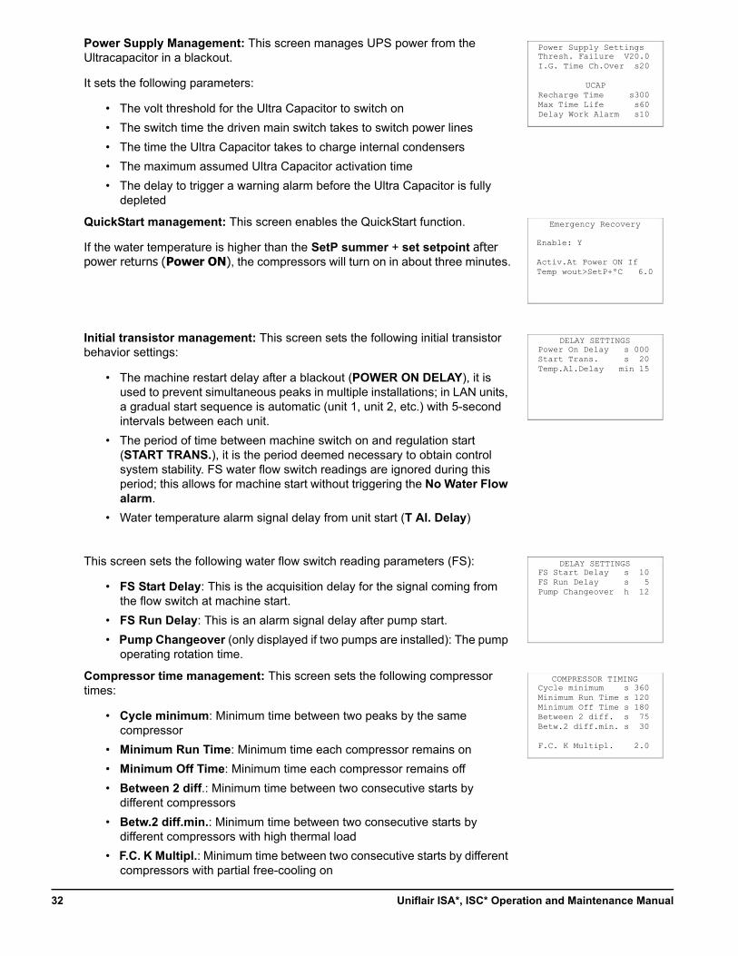
Power Supply Management: This screen manages UPS power from the Ultracapacitor in a blackout.
It sets the following parameters:
• The volt threshold for the Ultra Capacitor to switch on
• The switch time the driven main switch takes to switch power lines
• The time the Ultra Capacitor takes to charge internal condensers
• The maximum assumed Ultra Capacitor activation time
• The delay to trigger a warning alarm before the Ultra Capacitor is fully depleted
QuickStart management: This screen enables the QuickStart function.
If the water temperature is higher than the SetP summer + set setpoint after power returns (Power ON), the compressors will turn on in about three minutes.
Initial transistor management: This screen sets the following initial transistor behavior settings:
• The machine restart delay after a blackout (POWER ON DELAY), it is used to prevent simultaneous peaks in multiple installations; in LAN units, a gradual start sequence is automatic (unit 1, unit 2, etc.) with 5-second intervals between each unit.
• The period of time between machine switch on and regulation start (START TRANS.), it is the period deemed necessary to obtain control system stability. FS water flow switch readings are ignored during this period; this allows for machine start without triggering the No Water Flow alarm.
• Water temperature alarm signal delay from unit start (T Al. Delay)
This screen sets the following water flow switch reading parameters (FS):
• FS Start Delay: This is the acquisition delay for the signal coming from the flow switch at machine start.
• FS Run Delay: This is an alarm signal delay after pump start.
• Pump Changeover (only displayed if two pumps are installed): The pump operating rotation time.
Compressor time management: This screen sets the following compressor times:
• Cycle minimum: Minimum time between two peaks by the same compressor
• Minimum Run Time: Minimum time each compressor remains on
• Minimum Off Time: Minimum time each compressor remains off
• Between 2 diff.: Minimum time between two consecutive starts by different compressors
• Betw.2 diff.min.: Minimum time between two consecutive starts by different compressors with high thermal load
• F.C. K Multipl.: Minimum time between two consecutive starts by different compressors with partial free-cooling on
Emergency Recovery
Enable: Y
Activ.At Power ON IfTemp wout>SetP+ºC 6.0
DELAY SETTINGSPower On Delay s 000Start Trans. s 20Temp.Al.Delay min 15
Power Supply SettingsThresh. Failure V20.0I.G. Time Ch.Over s20
UCAPRecharge Time s300Max Time Life s60Delay Work Alarm s10
DELAY SETTINGSFS Start Delay s 10FS Run Delay s 5Pump Changeover h 12
COMPRESSOR TIMINGCycle minimum s 360Minimum Run Time s 120Minimum Off Time s 180Between 2 diff. s 75Betw.2 diff.min. s 30
F.C. K Multipl. 2.0
Uniflair ISA*, ISC* Operation and Maintenance Manual32
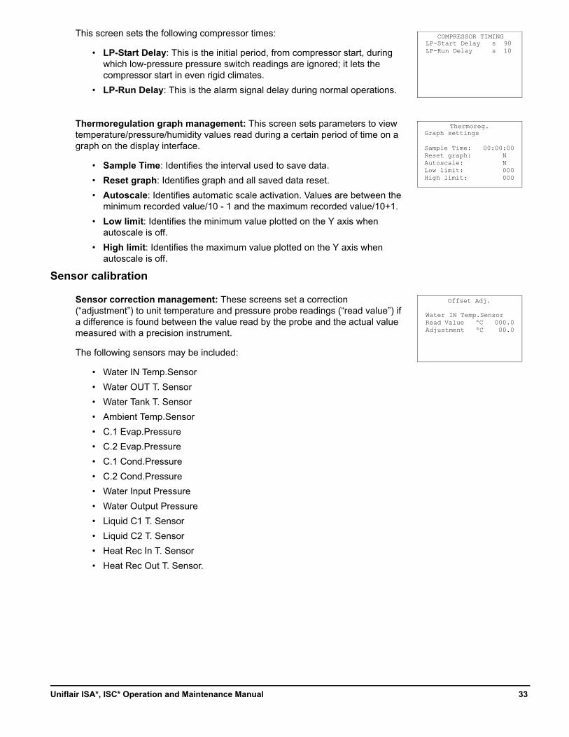
This screen sets the following compressor times:
• LP-Start Delay: This is the initial period, from compressor start, during which low-pressure pressure switch readings are ignored; it lets the compressor start in even rigid climates.
• LP-Run Delay: This is the alarm signal delay during normal operations.
Thermoregulation graph management: This screen sets parameters to view temperature/pressure/humidity values read during a certain period of time on a graph on the display interface.
• Sample Time: Identifies the interval used to save data.
• Reset graph: Identifies graph and all saved data reset.
• Autoscale: Identifies automatic scale activation. Values are between the minimum recorded value/10 - 1 and the maximum recorded value/10+1.
• Low limit: Identifies the minimum value plotted on the Y axis when autoscale is off.
• High limit: Identifies the maximum value plotted on the Y axis when autoscale is off.
Sensor calibration
Sensor correction management: These screens set a correction (“adjustment”) to unit temperature and pressure probe readings (“read value”) if a difference is found between the value read by the probe and the actual value measured with a precision instrument.
The following sensors may be included:
• Water IN Temp.Sensor
• Water OUT T. Sensor
• Water Tank T. Sensor
• Ambient Temp.Sensor
• C.1 Evap.Pressure
• C.2 Evap.Pressure
• C.1 Cond.Pressure
• C.2 Cond.Pressure
• Water Input Pressure
• Water Output Pressure
• Liquid C1 T. Sensor
• Liquid C2 T. Sensor
• Heat Rec In T. Sensor
• Heat Rec Out T. Sensor.
Thermoreg.Graph settings
Sample Time: 00:00:00Reset graph: NAutoscale: NLow limit: 000High limit: 000
Offset Adj.
Water IN Temp.SensorRead Value ºC 000.0Adjustment ºC 00.0
COMPRESSOR TIMINGLP-Start Delay s 90LP-Run Delay s 10
33Uniflair ISA*, ISC* Operation and Maintenance Manual
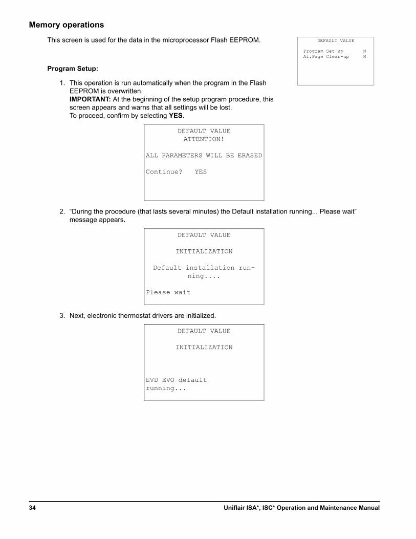
Memory operations
This screen is used for the data in the microprocessor Flash EEPROM.
Program Setup:
1. This operation is run automatically when the program in the Flash EEPROM is overwritten.IMPORTANT: At the beginning of the setup program procedure, this screen appears and warns that all settings will be lost.To proceed, confirm by selecting YES.
2. “During the procedure (that lasts several minutes) the Default installation running... Please wait” message appears.
3. Next, electronic thermostat drivers are initialized.
DEFAULT VALUE
Program Set up NAl.Page Clear-up N
DEFAULT VALUEATTENTION!
ALL PARAMETERS WILL BE ERASED
Continue? YES
DEFAULT VALUE
INITIALIZATION
Default installation run-ning....
Please wait
DEFAULT VALUE
INITIALIZATION
EVD EVO default running...
Uniflair ISA*, ISC* Operation and Maintenance Manual34
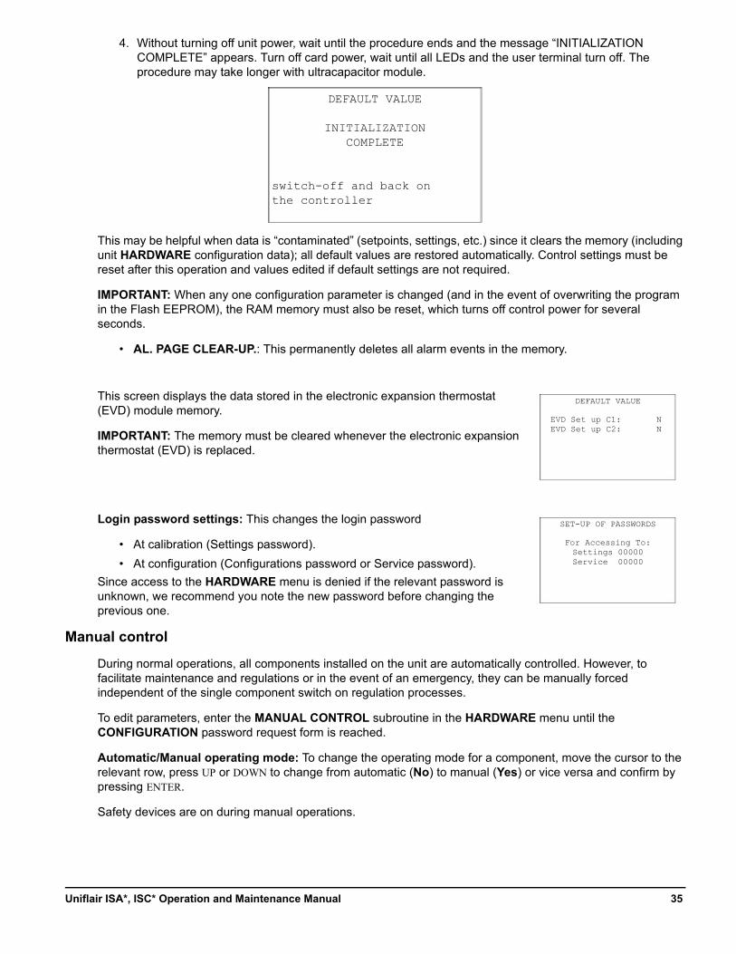
4. Without turning off unit power, wait until the procedure ends and the message “INITIALIZATION COMPLETE” appears. Turn off card power, wait until all LEDs and the user terminal turn off. The procedure may take longer with ultracapacitor module.
This may be helpful when data is “contaminated” (setpoints, settings, etc.) since it clears the memory (including unit HARDWARE configuration data); all default values are restored automatically. Control settings must be reset after this operation and values edited if default settings are not required.
IMPORTANT: When any one configuration parameter is changed (and in the event of overwriting the program in the Flash EEPROM), the RAM memory must also be reset, which turns off control power for several seconds.
• AL. PAGE CLEAR-UP.: This permanently deletes all alarm events in the memory.
This screen displays the data stored in the electronic expansion thermostat (EVD) module memory.
IMPORTANT: The memory must be cleared whenever the electronic expansion thermostat (EVD) is replaced.
Login password settings: This changes the login password
• At calibration (Settings password).
• At configuration (Configurations password or Service password).
Since access to the HARDWARE menu is denied if the relevant password is unknown, we recommend you note the new password before changing the previous one.
Manual control
During normal operations, all components installed on the unit are automatically controlled. However, to facilitate maintenance and regulations or in the event of an emergency, they can be manually forced independent of the single component switch on regulation processes.
To edit parameters, enter the MANUAL CONTROL subroutine in the HARDWARE menu until the CONFIGURATION password request form is reached.
Automatic/Manual operating mode: To change the operating mode for a component, move the cursor to the relevant row, press UP or DOWN to change from automatic (No) to manual (Yes) or vice versa and confirm by pressing ENTER.
Safety devices are on during manual operations.
DEFAULT VALUE
INITIALIZATION COMPLETE
switch-off and back on the controller
DEFAULT VALUE
EVD Set up C1: NEVD Set up C2: N
SET-UP OF PASSWORDS
For Accessing To:Settings 00000Service 00000
35Uniflair ISA*, ISC* Operation and Maintenance Manual
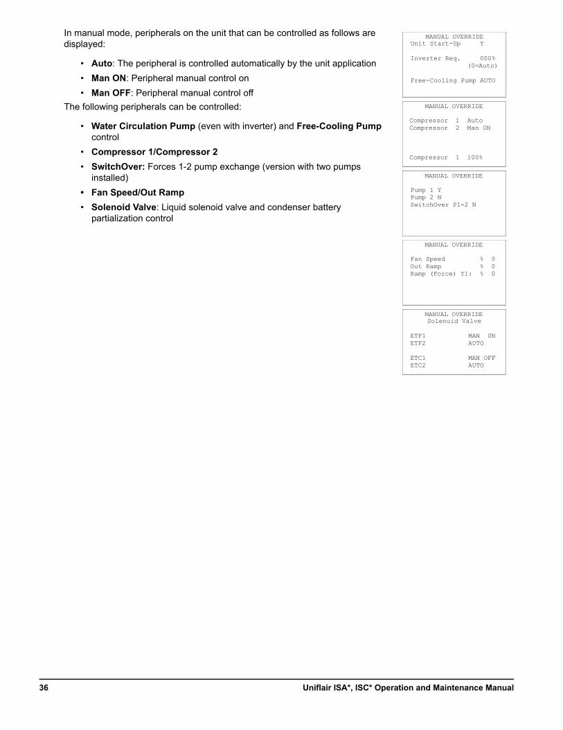
In manual mode, peripherals on the unit that can be controlled as follows are displayed:
• Auto: The peripheral is controlled automatically by the unit application
• Man ON: Peripheral manual control on
• Man OFF: Peripheral manual control off
The following peripherals can be controlled:
• Water Circulation Pump (even with inverter) and Free-Cooling Pump control
• Compressor 1/Compressor 2
• SwitchOver: Forces 1-2 pump exchange (version with two pumps installed)
• Fan Speed/Out Ramp
• Solenoid Valve: Liquid solenoid valve and condenser battery partialization control
MANUAL OVERRIDE
Compressor 1 AutoCompressor 2 Man ON
Compressor 1 100%
MANUAL OVERRIDE
Pump 1 YPump 2 NSwitchOver P1-2 N
MANUAL OVERRIDEUnit Start-Up Y
Inverter Req. 000%(0=Auto)
Free-Cooling Pump AUTO
MANUAL OVERRIDE
Fan Speed % 0Out Ramp % 0Ramp (Force) Y1: % 0
MANUAL OVERRIDESolenoid Valve
ETF1 MAN 0NETF2 AUTO
ETC1 MAN OFFETC2 AUTO
Uniflair ISA*, ISC* Operation and Maintenance Manual36
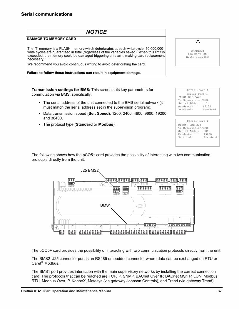
Serial communications
Transmission settings for BMS: This screen sets key parameters for commutation via BMS, specifically:
• The serial address of the unit connected to the BMS serial network (it must match the serial address set in the supervision program).
• Data transmission speed (Ser. Speed): 1200, 2400, 4800, 9600, 19200, and 38400.
• The protocol type (Standard or Modbus).
The following shows how the pCO5+ card provides the possibility of interacting with two communication protocols directly from the unit.
The pCO5+ card provides the possibility of interacting with two communication protocols directly from the unit.
The BMS2–J25 connector port is an RS485 embedded connector where data can be exchanged on RTU or Carel® Modbus.
The BMS1 port provides interaction with the main supervisory networks by installing the correct connection card. The protocols that can be reached are TCP/IP, SNMP, BACnet Over IP, BACnet MS/TP, LON, Modbus RTU, Modbus Over IP, KonneX, Metasys (via gateway Johnson Controls), and Trend (via gateway Trend).
NOTICEDAMAGE TO MEMORY CARD
The ‘T’ memory is a FLASH memory which deteriorates at each write cycle. 10,000,000 write cycles are guaranteed in total (regardless of the variables saved). When this limit is exceeded, the memory could be damaged triggering an alarm, making card replacement necessary.
We recommend you avoid continuous writing to avoid deteriorating the card.
Failure to follow these instructions can result in equipment damage.
Serial Port 1 (BMS1-Ser.Card)To Supervision/BMSSerial Addr.: 1Baudrate: 19200Protocol: Standard
Serial Port 1
RS485 (BMS-J25)To Supervision/BMSSerial Addr.: Baudrate:Protocol:
Serial Port 1
WARNING:Too many BMS
Write from BMS
00119200Standard
na52
98b
pCO5
J11 pLAN
J25 BMS2 J26 FBUS2
Tx/Rx GND
Tx/Rx GND Tx/Rx GND
J12 J13 J14J15 J16 J17 J18
J21 J22 J23 FBUS2
J19 J20
J8
J7
J6J5J4J3J2J24J1
J10
C7
NO7
C7
NO8
C8
NC8
ID2
ID4
ID6
J25 BMS2
BMS1
37Uniflair ISA*, ISC* Operation and Maintenance Manual
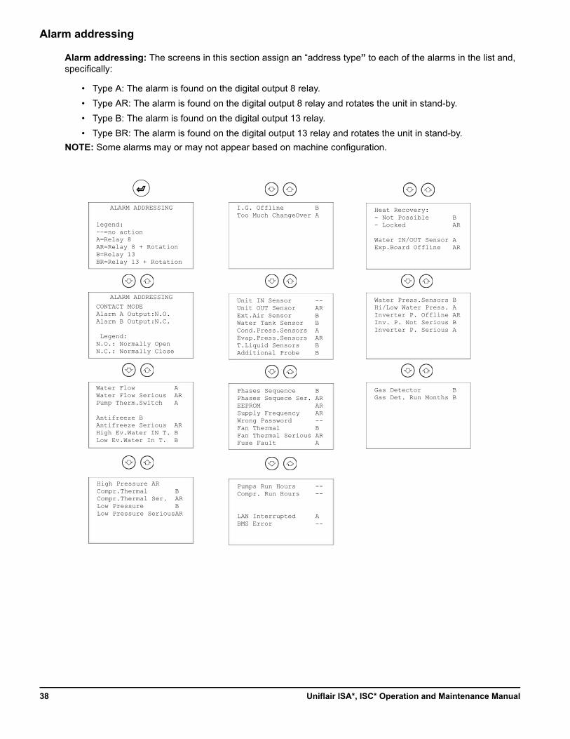
Alarm addressing
Alarm addressing: The screens in this section assign an “address type” to each of the alarms in the list and, specifically:
• Type A: The alarm is found on the digital output 8 relay.
• Type AR: The alarm is found on the digital output 8 relay and rotates the unit in stand-by.
• Type B: The alarm is found on the digital output 13 relay.
• Type BR: The alarm is found on the digital output 13 relay and rotates the unit in stand-by.
NOTE: Some alarms may or may not appear based on machine configuration.
legend:--=no actionA=Relay 8AR=Relay 8 + RotationB=Relay 13BR=Relay 13 + Rotation
ALARM ADDRESSING
Water Flow AWater Flow Serious ARPump Therm.Switch A
Antifreeze BAntifreeze Serious ARHigh Ev.Water IN T. BLow Ev.Water In T. B
High Pressure ARCompr.Thermal BCompr.Thermal Ser. ARLow Pressure BLow Pressure SeriousAR
I.G. Offline BToo Much ChangeOver A
Unit IN Sensor --Unit OUT Sensor ARExt.Air Sensor BWater Tank Sensor BCond.Press.Sensors AEvap.Press.Sensors ART.Liquid Sensors BAdditional Probe B
Phases Sequence BPhases Sequece Ser. AREEPROM ARSupply Frequency ARWrong Password --Fan Thermal BFan Thermal Serious ARFuse Fault A
Pumps Run Hours --Compr. Run Hours --
LAN Interrupted ABMS Error --
Heat Recovery:- Not Possible B- Locked AR
Water IN/OUT Sensor AExp.Board Offline AR
CONTACT MODEAlarm A Output:N.O.Alarm B Output:N.C.
Legend:N.O.: Normally OpenN.C.: Normally Close
ALARM ADDRESSING Water Press.Sensors BHi/Low Water Press. AInverter P. Offline ARInv. P. Not Serious BInverter P. Serious A
Gas Detector BGas Det. Run Months B
Uniflair ISA*, ISC* Operation and Maintenance Manual38
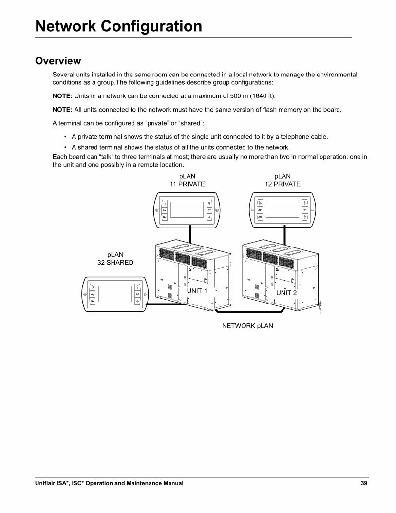
Network Configuration
OverviewSeveral units installed in the same room can be connected in a local network to manage the environmental conditions as a group.The following guidelines describe group configurations:
NOTE: Units in a network can be connected at a maximum of 500 m (1640 ft).
NOTE: All units connected to the network must have the same version of flash memory on the board.
A terminal can be configured as “private” or “shared”:
• A private terminal shows the status of the single unit connected to it by a telephone cable.
• A shared terminal shows the status of all the units connected to the network.
Each board can “talk” to three terminals at most; there are usually no more than two in normal operation: one in the unit and one possibly in a remote location.
na57
53b
pLAN32 SHARED
pLAN11 PRIVATE
pLAN12 PRIVATE
NETWORK pLAN
UNIT 1 UNIT 2
39Uniflair ISA*, ISC* Operation and Maintenance Manual
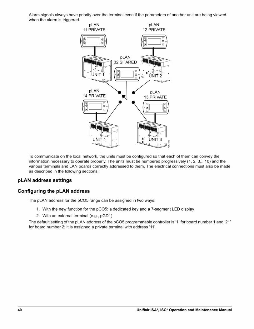
Alarm signals always have priority over the terminal even if the parameters of another unit are being viewed when the alarm is triggered.
To communicate on the local network, the units must be configured so that each of them can convey the information necessary to operate properly. The units must be numbered progressively (1, 2, 3,...10) and the various terminals and LAN boards correctly addressed to them. The electrical connections must also be made as described in the following sections.
pLAN address settings
Configuring the pLAN address
The pLAN address for the pCO5 range can be assigned in two ways:
1. With the new function for the pCO5: a dedicated key and a 7-segment LED display
2. With an external terminal (e.g., pGD1)
The default setting of the pLAN address of the pCO5 programmable controller is ‘1’ for board number 1 and ‘21’ for board number 2; it is assigned a private terminal with address ‘11’.
na57
54b
pLAN32 SHARED
pLAN11 PRIVATE
pLAN12 PRIVATE
UNIT 1 UNIT 2
pLAN14 PRIVATE
pLAN13 PRIVATE
UNIT 4 UNIT 3
Uniflair ISA*, ISC* Operation and Maintenance Manual40
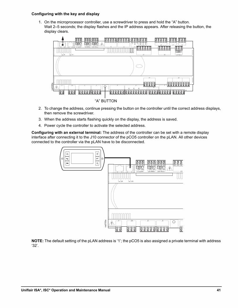
Configuring with the key and display
1. On the microprocessor controller, use a screwdriver to press and hold the “A” button. Wait 2–5 seconds; the display flashes and the IP address appears. After releasing the button, the display clears.
2. To change the address, continue pressing the button on the controller until the correct address displays, then remove the screwdriver.
3. When the address starts flashing quickly on the display, the address is saved.
4. Power cycle the controller to activate the selected address.
Configuring with an external terminal: The address of the controller can be set with a remote display interface after connecting it to the J10 connector of the pCO5 controller on the pLAN. All other devices connected to the controller via the pLAN have to be disconnected.
NOTE: The default setting of the pLAN address is ‘1’; the pCO5 is also assigned a private terminal with address ‘32’.
na52
98a
pCO5
J11 pLAN J25 BMS2 J26 FBUS2Tx/Rx GND Tx/Rx GND Tx/Rx GND
J12 J13 J14J15 J16 J17 J18
J21 J22 J23 FBUS2
J19 J20
J8
J7
J6J5J4J3J2J24J1
J9 J10
C7
NO7
C7
NO8
C8
NC8
ID2
ID4
ID6
“A” BUTTONna
5755
a
pCO5
J11 pLAN J25 BMS2 J26 FBUS2Tx/Rx GND Tx/Rx GND Tx/Rx GND
J12
J3J2J24J1
J9 J10
41Uniflair ISA*, ISC* Operation and Maintenance Manual
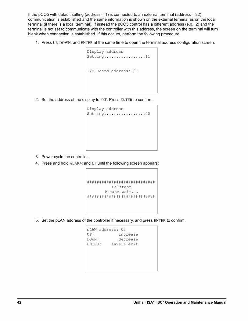
If the pCO5 with default setting (address = 1) is connected to an external terminal (address = 32), communication is established and the same information is shown on the external terminal as on the local terminal (if there is a local terminal). If instead the pCO5 control has a different address (e.g., 2) and the terminal is not set to communicate with the controller with this address, the screen on the terminal will turn blank when connection is established. If this occurs, perform the following procedure:
1. Press UP, DOWN, and ENTER at the same time to open the terminal address configuration screen.
2. Set the address of the display to ‘00’. Press ENTER to confirm.
3. Power cycle the controller.
4. Press and hold ALARM and UP until the following screen appears:
5. Set the pLAN address of the controller if necessary, and press ENTER to confirm.
Display addressSetting................:11
I/O Board address: 01
Display addressSetting................:00
############################Selftest
Please wait...############################
pLAN address: 02UP:DOWN:ENTER:
increasedecrease
save & exit
Uniflair ISA*, ISC* Operation and Maintenance Manual42
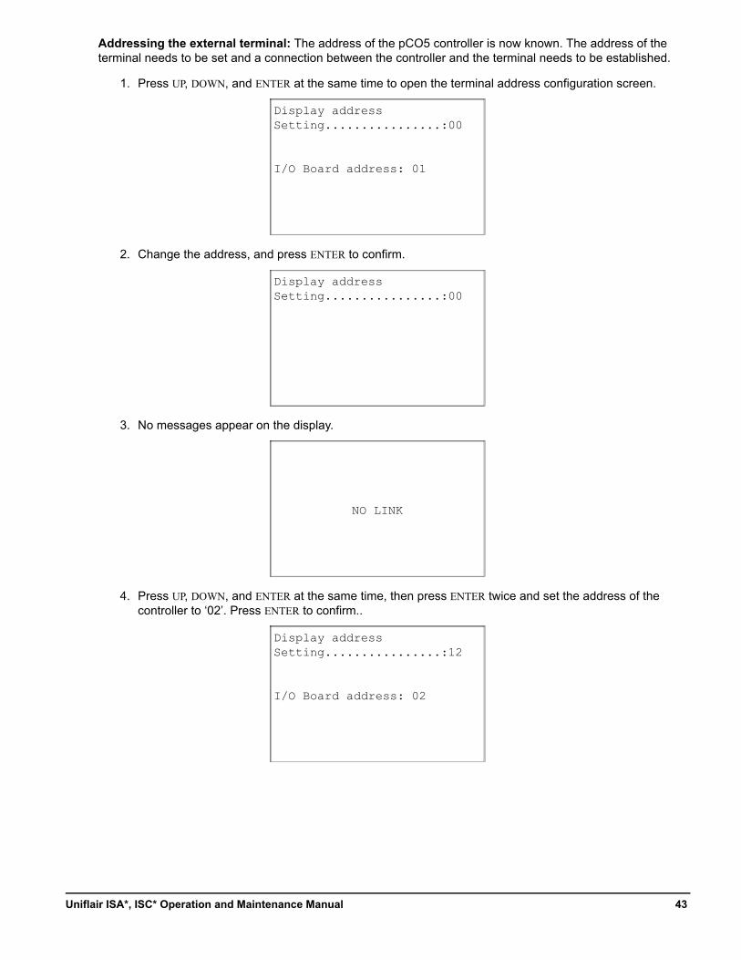
Addressing the external terminal: The address of the pCO5 controller is now known. The address of the terminal needs to be set and a connection between the controller and the terminal needs to be established.
1. Press UP, DOWN, and ENTER at the same time to open the terminal address configuration screen.
2. Change the address, and press ENTER to confirm.
3. No messages appear on the display.
4. Press UP, DOWN, and ENTER at the same time, then press ENTER twice and set the address of the controller to ‘02’. Press ENTER to confirm..
Display addressSetting................:00
I/O Board address: 01
Display addressSetting................:00
NO LINK
Display addressSetting................:12
I/O Board address: 02
43Uniflair ISA*, ISC* Operation and Maintenance Manual
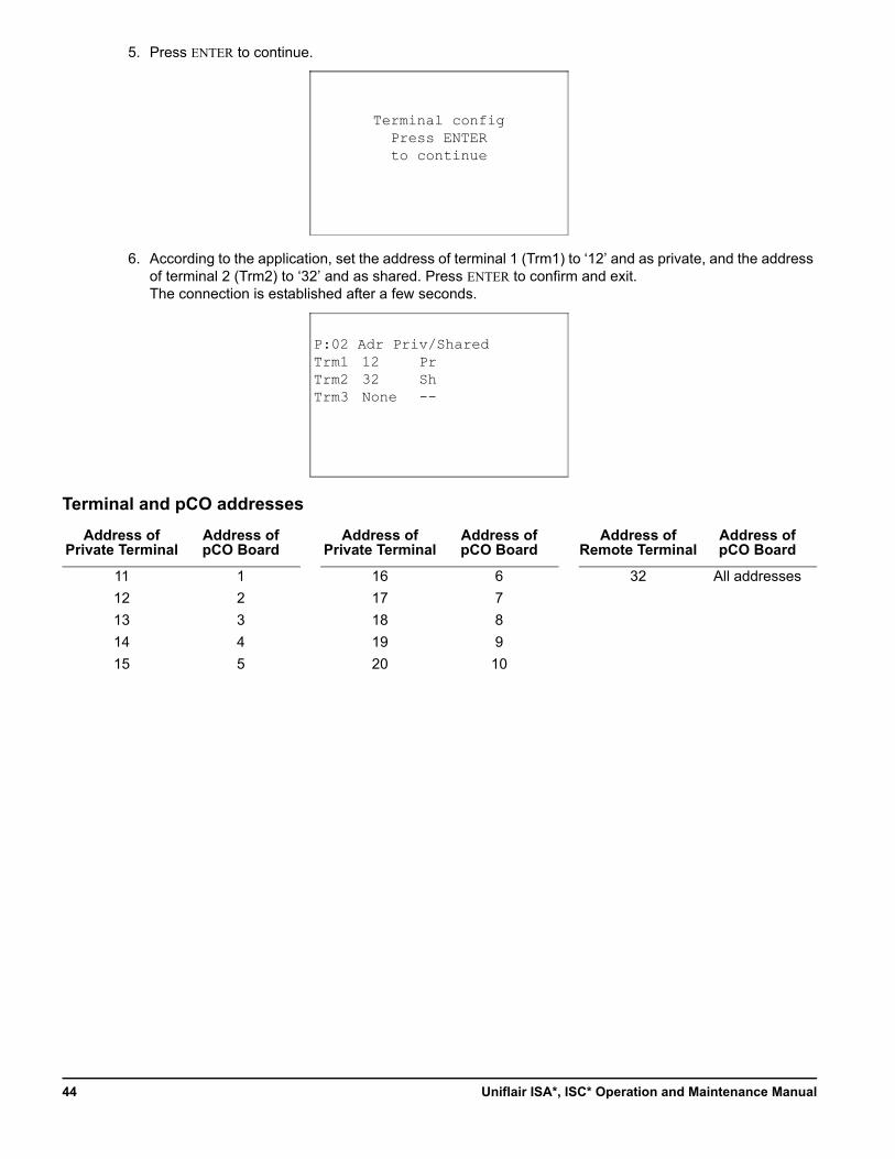
5. Press ENTER to continue.
6. According to the application, set the address of terminal 1 (Trm1) to ‘12’ and as private, and the address of terminal 2 (Trm2) to ‘32’ and as shared. Press ENTER to confirm and exit.The connection is established after a few seconds.
Terminal and pCO addresses
Address of Private Terminal
Address of pCO Board
Address of Private Terminal
Address of pCO Board
Address of Remote Terminal
Address of pCO Board
11 1 16 6 32 All addresses
12 2 17 7
13 3 18 8
14 4 19 9
15 5 20 10
Terminal configPress ENTERto continue
P:02 Adr Priv/SharedTrm1Trm2Trm3
1232None
PrSh--
Uniflair ISA*, ISC* Operation and Maintenance Manual44
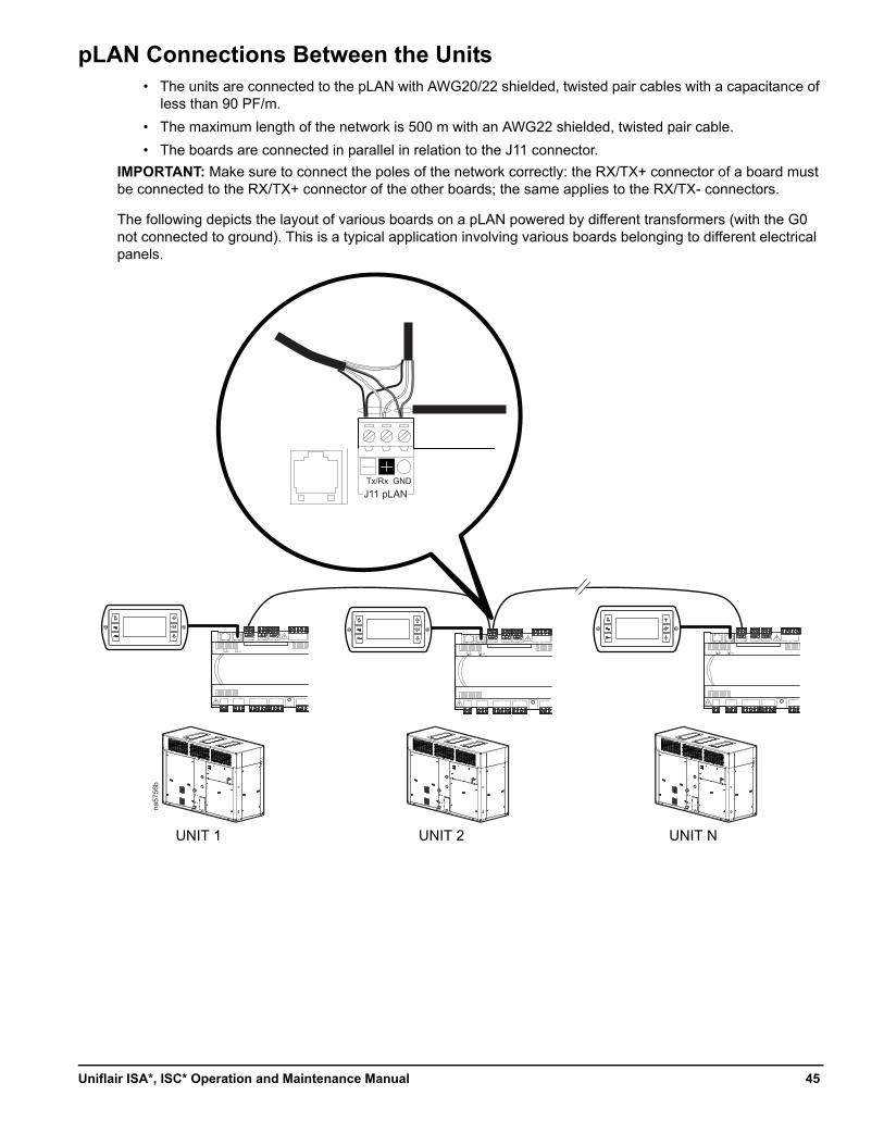
pLAN Connections Between the Units• The units are connected to the pLAN with AWG20/22 shielded, twisted pair cables with a capacitance of
less than 90 PF/m.
• The maximum length of the network is 500 m with an AWG22 shielded, twisted pair cable.
• The boards are connected in parallel in relation to the J11 connector.
IMPORTANT: Make sure to connect the poles of the network correctly: the RX/TX+ connector of a board must be connected to the RX/TX+ connector of the other boards; the same applies to the RX/TX- connectors.
The following depicts the layout of various boards on a pLAN powered by different transformers (with the G0 not connected to ground). This is a typical application involving various boards belonging to different electrical panels.
na57
56b
J11 pLANTx/Rx GND
pCO5
J11 pLAN J25 BMS2 J26 FBUS2Tx/Rx GND Tx/Rx GND Tx/Rx GND
J12
J3J2J24J1
J9 J10
pCO5
J11 pLAN J25 BMS2 J26 FBUS2Tx/Rx GND Tx/Rx GND Tx/Rx GND
J12
J3J2J24J1
J9 J10
pCO5
J11 pLAN J25 BMS2 J26 FBUS2Tx/Rx GND Tx/Rx GND Tx/Rx GND
J12
J3J2J24J1
J9 J10
UNIT 1 UNIT 2 UNIT N
45Uniflair ISA*, ISC* Operation and Maintenance Manual
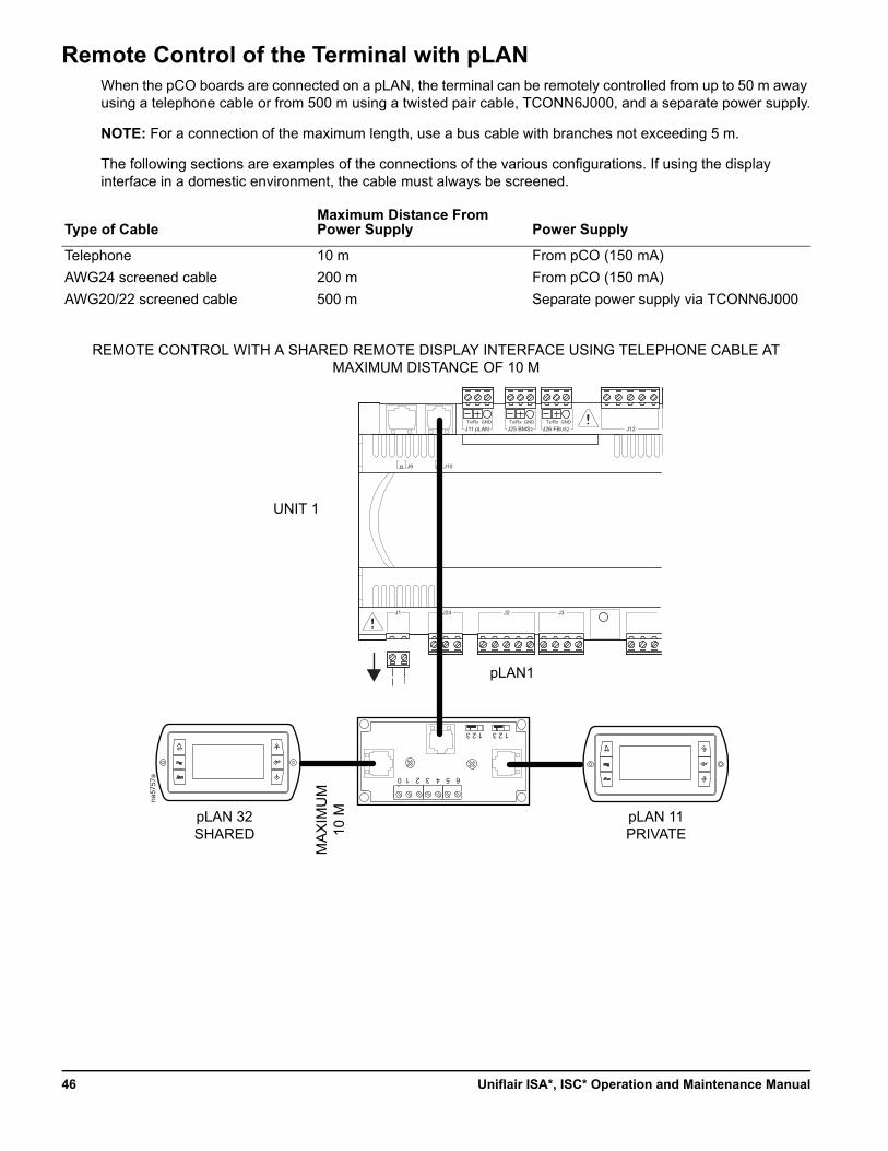
Remote Control of the Terminal with pLANWhen the pCO boards are connected on a pLAN, the terminal can be remotely controlled from up to 50 m away using a telephone cable or from 500 m using a twisted pair cable, TCONN6J000, and a separate power supply.
NOTE: For a connection of the maximum length, use a bus cable with branches not exceeding 5 m.
The following sections are examples of the connections of the various configurations. If using the display interface in a domestic environment, the cable must always be screened.
Type of CableMaximum Distance From Power Supply Power Supply
Telephone 10 m From pCO (150 mA)
AWG24 screened cable 200 m From pCO (150 mA)
AWG20/22 screened cable 500 m Separate power supply via TCONN6J000
pCO5
J11 pLAN J25 BMS2 J26 FBUS2Tx/Rx GND Tx/Rx GND Tx/Rx GND
J12
J3J2J24J1
J9 J10
6 5 4 3 2 1 0
1 2 3 1 2 3
na57
57a
UNIT 1
REMOTE CONTROL WITH A SHARED REMOTE DISPLAY INTERFACE USING TELEPHONE CABLE AT MAXIMUM DISTANCE OF 10 M
pLAN1
pLAN 32SHARED
pLAN 11PRIVATE
MA
XIM
UM
10
M
Uniflair ISA*, ISC* Operation and Maintenance Manual46
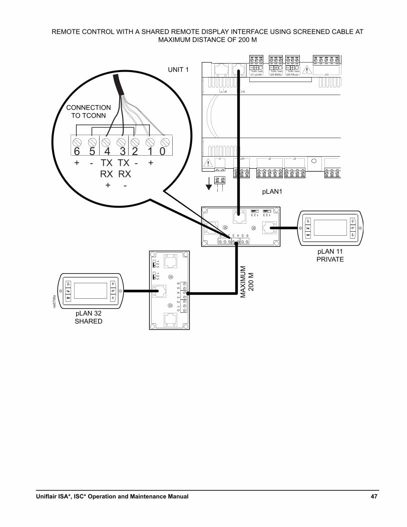
pCO5
J11 pLAN J25 BMS2 J26 FBUS2Tx/Rx GND Tx/Rx GND Tx/Rx GND
J12
J3J2J24J1
J9 J10
6 5 4 3 2 1 0
1 2 3 1 2 3
na57
58a
6 5 4 3 2 1 0
1 2 31 2 3
6 5 4 3 2 1 0+ - TX TX - + RX RX + -
UNIT 1
REMOTE CONTROL WITH A SHARED REMOTE DISPLAY INTERFACE USING SCREENED CABLE AT MAXIMUM DISTANCE OF 200 M
pLAN1
pLAN 32SHARED
pLAN 11PRIVATE
MA
XIM
UM
200
M
CONNECTION TO TCONN
47Uniflair ISA*, ISC* Operation and Maintenance Manual
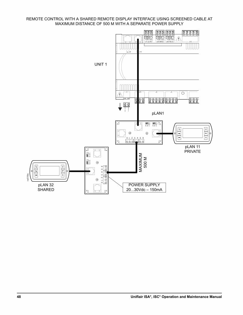
pCO5
J11 pLAN J25 BMS2 J26 FBUS2Tx/Rx GND Tx/Rx GND Tx/Rx GND
J12
J3J2J24J1
J9 J10
6 5 4 3 2 1 0
1 2 3 1 2 3
na57
59a
6 5 4 3 2 1 0
1 2 31 2 3
UNIT 1
REMOTE CONTROL WITH A SHARED REMOTE DISPLAY INTERFACE USING SCREENED CABLE AT MAXIMUM DISTANCE OF 500 M WITH A SEPARATE POWER SUPPLY
pLAN1
pLAN 32SHARED
pLAN 11PRIVATE
MA
XIM
UM
500
M
POWER SUPPLY20...30Vdc – 150mA
Uniflair ISA*, ISC* Operation and Maintenance Manual48
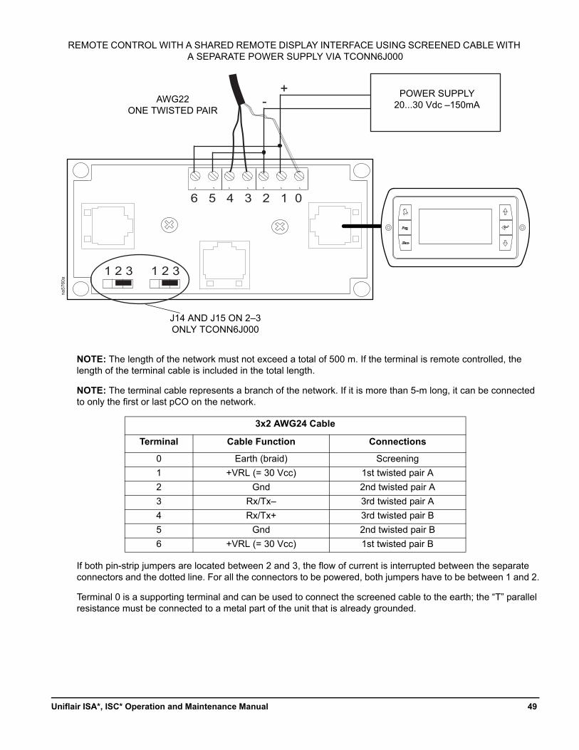
NOTE: The length of the network must not exceed a total of 500 m. If the terminal is remote controlled, the length of the terminal cable is included in the total length.
NOTE: The terminal cable represents a branch of the network. If it is more than 5-m long, it can be connected to only the first or last pCO on the network.
If both pin-strip jumpers are located between 2 and 3, the flow of current is interrupted between the separate connectors and the dotted line. For all the connectors to be powered, both jumpers have to be between 1 and 2.
Terminal 0 is a supporting terminal and can be used to connect the screened cable to the earth; the “T” parallel resistance must be connected to a metal part of the unit that is already grounded.
3x2 AWG24 Cable
Terminal Cable Function Connections
0 Earth (braid) Screening
1 +VRL (= 30 Vcc) 1st twisted pair A
2 Gnd 2nd twisted pair A
3 Rx/Tx– 3rd twisted pair A
4 Rx/Tx+ 3rd twisted pair B
5 Gnd 2nd twisted pair B
6 +VRL (= 30 Vcc) 1st twisted pair B
6 5 4 3 2 1 0
1 2 31 2 3
+ -
na57
60a
REMOTE CONTROL WITH A SHARED REMOTE DISPLAY INTERFACE USING SCREENED CABLE WITH A SEPARATE POWER SUPPLY VIA TCONN6J000
POWER SUPPLY20...30 Vdc –150mA
AWG22ONE TWISTED PAIR
J14 AND J15 ON 2–3ONLY TCONN6J000
49Uniflair ISA*, ISC* Operation and Maintenance Manual
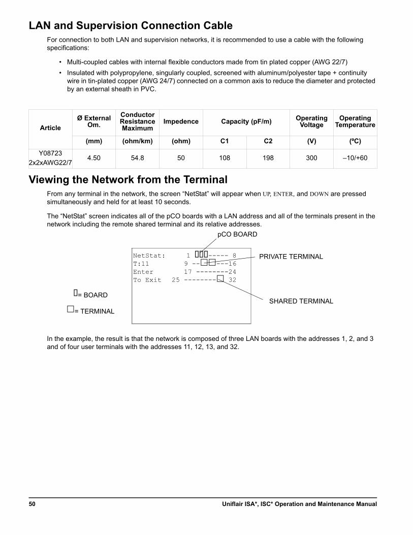
LAN and Supervision Connection CableFor connection to both LAN and supervision networks, it is recommended to use a cable with the following specifications:
• Multi-coupled cables with internal flexible conductors made from tin plated copper (AWG 22/7)
• Insulated with polypropylene, singularly coupled, screened with aluminum/polyester tape + continuity wire in tin-plated copper (AWG 24/7) connected on a common axis to reduce the diameter and protected by an external sheath in PVC.
Viewing the Network from the TerminalFrom any terminal in the network, the screen “NetStat” will appear when UP, ENTER, and DOWN are pressed simultaneously and held for at least 10 seconds.
The “NetStat” screen indicates all of the pCO boards with a LAN address and all of the terminals present in the network including the remote shared terminal and its relative addresses.
In the example, the result is that the network is composed of three LAN boards with the addresses 1, 2, and 3 and of four user terminals with the addresses 11, 12, 13, and 32.
Article
Ø External Om.
Conductor Resistance Maximum
Impedence Capacity (pF/m) Operating Voltage
Operating Temperature
(mm) (ohm/km) (ohm) C1 C2 (V) (ºC)
Y08723
2x2xAWG22/74.50 54.8 50 108 198 300 –10/+60
NetStat:T:11EnterTo Exit
1 ----- 89 -----1617 --------24
25 -------- 32
pCO BOARD
PRIVATE TERMINAL
SHARED TERMINAL= BOARD
= TERMINAL
Uniflair ISA*, ISC* Operation and Maintenance Manual50
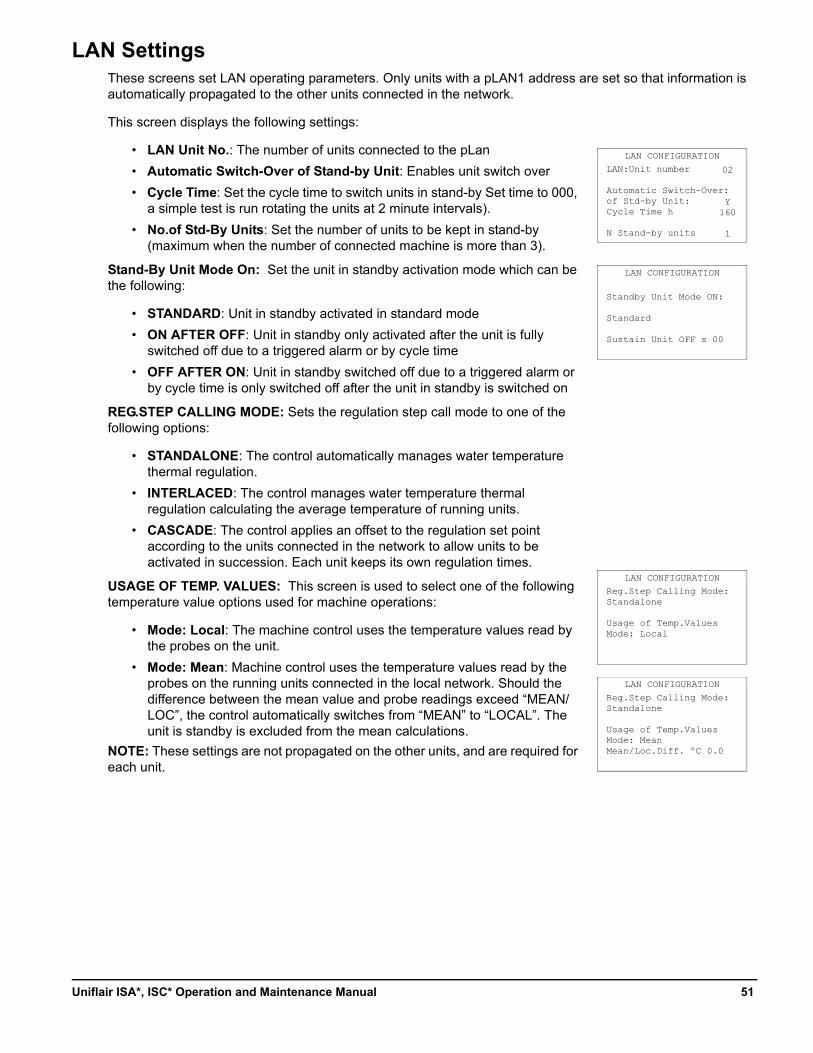
LAN SettingsThese screens set LAN operating parameters. Only units with a pLAN1 address are set so that information is automatically propagated to the other units connected in the network.
This screen displays the following settings:
• LAN Unit No.: The number of units connected to the pLan
• Automatic Switch-Over of Stand-by Unit: Enables unit switch over
• Cycle Time: Set the cycle time to switch units in stand-by Set time to 000, a simple test is run rotating the units at 2 minute intervals).
• No.of Std-By Units: Set the number of units to be kept in stand-by (maximum when the number of connected machine is more than 3).
Stand-By Unit Mode On: Set the unit in standby activation mode which can be the following:
• STANDARD: Unit in standby activated in standard mode
• ON AFTER OFF: Unit in standby only activated after the unit is fully switched off due to a triggered alarm or by cycle time
• OFF AFTER ON: Unit in standby switched off due to a triggered alarm or by cycle time is only switched off after the unit in standby is switched on
REG.STEP CALLING MODE: Sets the regulation step call mode to one of the following options:
• STANDALONE: The control automatically manages water temperature thermal regulation.
• INTERLACED: The control manages water temperature thermal regulation calculating the average temperature of running units.
• CASCADE: The control applies an offset to the regulation set point according to the units connected in the network to allow units to be activated in succession. Each unit keeps its own regulation times.
USAGE OF TEMP. VALUES: This screen is used to select one of the following temperature value options used for machine operations:
• Mode: Local: The machine control uses the temperature values read by the probes on the unit.
• Mode: Mean: Machine control uses the temperature values read by the probes on the running units connected in the local network. Should the difference between the mean value and probe readings exceed “MEAN/LOC”, the control automatically switches from “MEAN” to “LOCAL”. The unit is standby is excluded from the mean calculations.
NOTE: These settings are not propagated on the other units, and are required for each unit.
LAN:Unit number
Automatic Switch-Over:of Std-by Unit:Cycle Time h
N Stand-by units
LAN CONFIGURATION
Standby Unit Mode ON:
Standard
Sustain Unit OFF s 00
LAN CONFIGURATION
Reg.Step Calling Mode:Standalone
Usage of Temp.ValuesMode: Local
LAN CONFIGURATION
Reg.Step Calling Mode:Standalone
Usage of Temp.ValuesMode: MeanMean/Loc.Diff. ºC 0.0
LAN CONFIGURATION
02
Y160
1
51Uniflair ISA*, ISC* Operation and Maintenance Manual
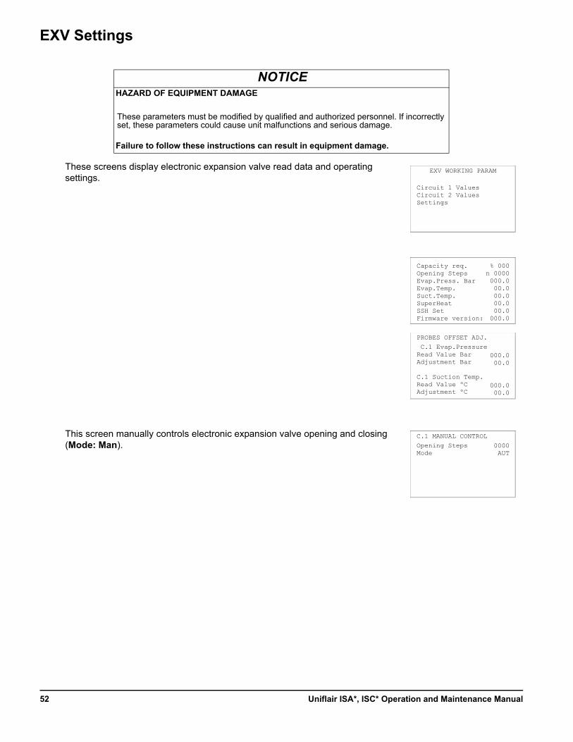
EXV Settings
These screens display electronic expansion valve read data and operating settings.
This screen manually controls electronic expansion valve opening and closing (Mode: Man).
NOTICEHAZARD OF EQUIPMENT DAMAGE
These parameters must be modified by qualified and authorized personnel. If incorrectly set, these parameters could cause unit malfunctions and serious damage.
Failure to follow these instructions can result in equipment damage.
Circuit 1 ValuesCircuit 2 ValuesSettings
EXV WORKING PARAM
C.1 Evap.PressureRead Value BarAdjustment Bar
C.1 Suction Temp.Read Value ºCAdjustment ºC
PROBES OFFSET ADJ.
Opening StepsMode
C.1 MANUAL CONTROL
Capacity req.Opening StepsEvap.Press. BarEvap.Temp.Suct.Temp.SuperHeatSSH SetFirmware version:
% 000n 0000000.000.000.000.000.0
000.0
000.000.0
000.000.0
0000AUT
Uniflair ISA*, ISC* Operation and Maintenance Manual52
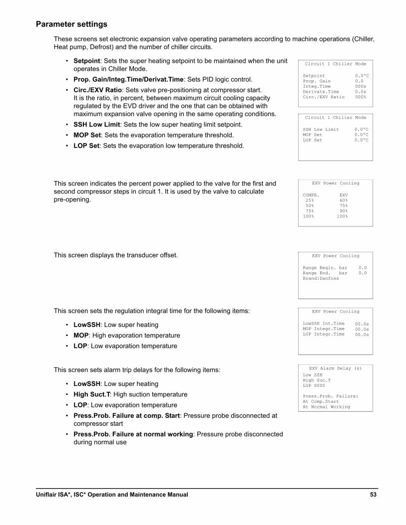
Parameter settings
These screens set electronic expansion valve operating parameters according to machine operations (Chiller, Heat pump, Defrost) and the number of chiller circuits.
• Setpoint: Sets the super heating setpoint to be maintained when the unit operates in Chiller Mode.
• Prop. Gain/Integ.Time/Derivat.Time: Sets PID logic control.
• Circ./EXV Ratio: Sets valve pre-positioning at compressor start. It is the ratio, in percent, between maximum circuit cooling capacity regulated by the EVD driver and the one that can be obtained with maximum expansion valve opening in the same operating conditions.
• SSH Low Limit: Sets the low super heating limit setpoint.
• MOP Set: Sets the evaporation temperature threshold.
• LOP Set: Sets the evaporation low temperature threshold.
This screen indicates the percent power applied to the valve for the first and second compressor steps in circuit 1. It is used by the valve to calculate pre-opening.
This screen displays the transducer offset.
This screen sets the regulation integral time for the following items:
• LowSSH: Low super heating
• MOP: High evaporation temperature
• LOP: Low evaporation temperature
This screen sets alarm trip delays for the following items:
• LowSSH: Low super heating
• High Suct.T: High suction temperature
• LOP: Low evaporation temperature
• Press.Prob. Failure at comp. Start: Pressure probe disconnected at compressor start
• Press.Prob. Failure at normal working: Pressure probe disconnected during normal use
SetpointProp. GainInteg.TimeDerivate.TimeCirc./EXV Ratio
Circuit 1 Chiller Mode
Circuit 1 Chiller Mode
COMPR. 25% 50% 75%100%
EXV Power Cooling
SSH Low LimitMOP SetLOP Set
0.0ºC0.0ºC0.0ºC
0.0ºC0.0 000s 0.0s 000%
Low SSHHigh Suc.TLOP 0000
Press.Prob. Failure:At Comp.StartAt Normal Working
EXV Alarm Delay (s)
LowSSH Int.TimeMOP Integr.TimeLOP Integr.Time
EXV Power Cooling
00.0s00.0s00.0s
Range Begin. bar 0.0Range End. bar 0.0Brand:Danfoss
EXV Power Cooling
EXV 60% 75% 90%100%
53Uniflair ISA*, ISC* Operation and Maintenance Manual
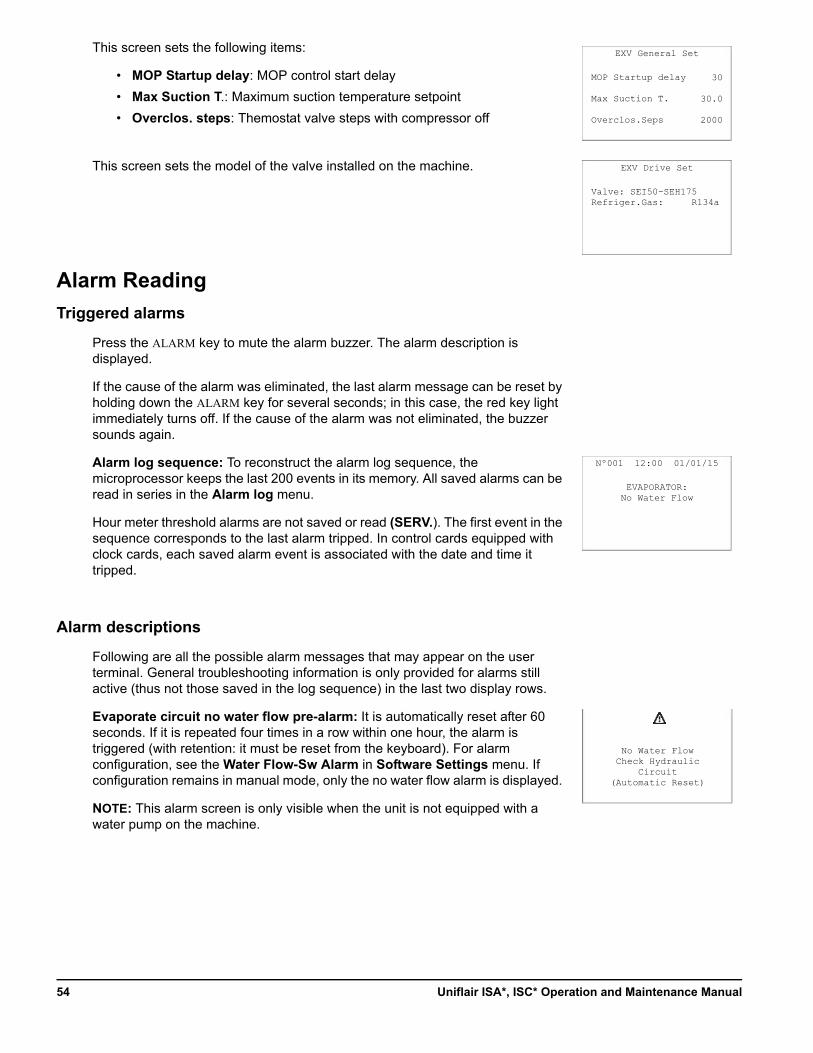
This screen sets the following items:
• MOP Startup delay: MOP control start delay
• Max Suction T.: Maximum suction temperature setpoint
• Overclos. steps: Themostat valve steps with compressor off
This screen sets the model of the valve installed on the machine.
Alarm Reading
Triggered alarms
Press the ALARM key to mute the alarm buzzer. The alarm description is displayed.
If the cause of the alarm was eliminated, the last alarm message can be reset by holding down the ALARM key for several seconds; in this case, the red key light immediately turns off. If the cause of the alarm was not eliminated, the buzzer sounds again.
Alarm log sequence: To reconstruct the alarm log sequence, the microprocessor keeps the last 200 events in its memory. All saved alarms can be read in series in the Alarm log menu.
Hour meter threshold alarms are not saved or read (SERV.). The first event in the sequence corresponds to the last alarm tripped. In control cards equipped with clock cards, each saved alarm event is associated with the date and time it tripped.
Alarm descriptions
Following are all the possible alarm messages that may appear on the user terminal. General troubleshooting information is only provided for alarms still active (thus not those saved in the log sequence) in the last two display rows.
Evaporate circuit no water flow pre-alarm: It is automatically reset after 60 seconds. If it is repeated four times in a row within one hour, the alarm is triggered (with retention: it must be reset from the keyboard). For alarm configuration, see the Water Flow-Sw Alarm in Software Settings menu. If configuration remains in manual mode, only the no water flow alarm is displayed.
NOTE: This alarm screen is only visible when the unit is not equipped with a water pump on the machine.
MOP Startup delay
Max Suction T.
Overclos.Seps
EXV General Set
Valve: SEI50-SEH175Refriger.Gas: R134a
EXV Drive Set
EVAPORATOR:No Water Flow
Nº001 12:00 01/01/15
No Water FlowCheck Hydraulic
Circuit(Automatic Reset)
30
30.0
2000
Uniflair ISA*, ISC* Operation and Maintenance Manual54
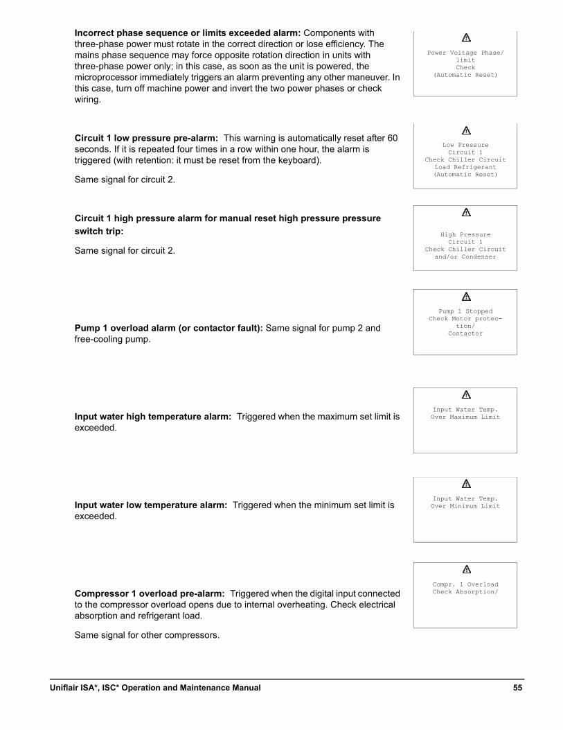
Incorrect phase sequence or limits exceeded alarm: Components with three-phase power must rotate in the correct direction or lose efficiency. The mains phase sequence may force opposite rotation direction in units with three-phase power only; in this case, as soon as the unit is powered, the microprocessor immediately triggers an alarm preventing any other maneuver. In this case, turn off machine power and invert the two power phases or check wiring.
Circuit 1 low pressure pre-alarm: This warning is automatically reset after 60 seconds. If it is repeated four times in a row within one hour, the alarm is triggered (with retention: it must be reset from the keyboard).
Same signal for circuit 2.
Circuit 1 high pressure alarm for manual reset high pressure pressure
switch trip:
Same signal for circuit 2.
Pump 1 overload alarm (or contactor fault): Same signal for pump 2 and free-cooling pump.
Input water high temperature alarm: Triggered when the maximum set limit is exceeded.
Input water low temperature alarm: Triggered when the minimum set limit is exceeded.
Compressor 1 overload pre-alarm: Triggered when the digital input connected to the compressor overload opens due to internal overheating. Check electrical absorption and refrigerant load.
Same signal for other compressors.
Low PressureCircuit 1
Check Chiller CircuitLoad Refrigerant(Automatic Reset)
High PressureCircuit 1
Check Chiller Circuitand/or Condenser
Pump 1 StoppedCheck Motor protec-
tion/Contactor
Input Water Temp.Over Minimum Limit
Compr. 1 OverloadCheck Absorption/
Power Voltage Phase/limitCheck
(Automatic Reset)
Input Water Temp.Over Maximum Limit
55Uniflair ISA*, ISC* Operation and Maintenance Manual
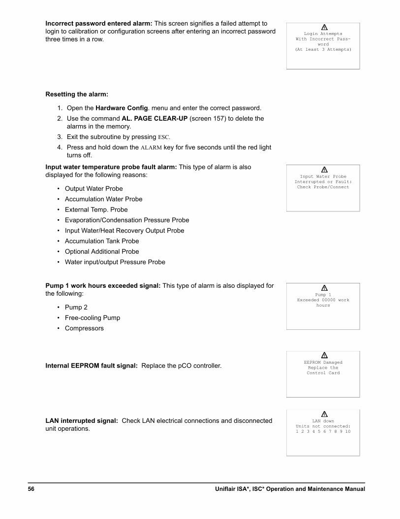
Incorrect password entered alarm: This screen signifies a failed attempt to login to calibration or configuration screens after entering an incorrect password three times in a row.
Resetting the alarm:
1. Open the Hardware Config. menu and enter the correct password.
2. Use the command AL. PAGE CLEAR-UP (screen 157) to delete the alarms in the memory.
3. Exit the subroutine by pressing ESC.
4. Press and hold down the ALARM key for five seconds until the red light turns off.
Input water temperature probe fault alarm: This type of alarm is also displayed for the following reasons:
• Output Water Probe
• Accumulation Water Probe
• External Temp. Probe
• Evaporation/Condensation Pressure Probe
• Input Water/Heat Recovery Output Probe
• Accumulation Tank Probe
• Optional Additional Probe
• Water input/output Pressure Probe
Pump 1 work hours exceeded signal: This type of alarm is also displayed for the following:
• Pump 2
• Free-cooling Pump
• Compressors
Internal EEPROM fault signal: Replace the pCO controller.
LAN interrupted signal: Check LAN electrical connections and disconnected unit operations.
Input Water ProbeInterrupted or Fault:Check Probe/Connect
Pump 1Exceeded 00000 work
hours
EEPROM DamagedReplace the Control Card
LAN downUnits not connected:1 2 3 4 5 6 7 8 9 10
Login AttemptsWith Incorrect Pass-
word(At least 3 Attempts)
Uniflair ISA*, ISC* Operation and Maintenance Manual56
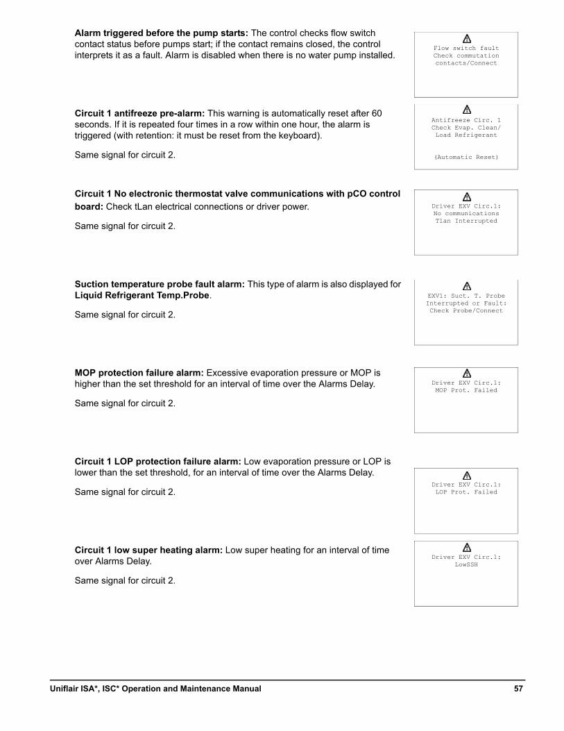
Alarm triggered before the pump starts: The control checks flow switch contact status before pumps start; if the contact remains closed, the control interprets it as a fault. Alarm is disabled when there is no water pump installed.
Circuit 1 antifreeze pre-alarm: This warning is automatically reset after 60 seconds. If it is repeated four times in a row within one hour, the alarm is triggered (with retention: it must be reset from the keyboard).
Same signal for circuit 2.
Circuit 1 No electronic thermostat valve communications with pCO control
board: Check tLan electrical connections or driver power.
Same signal for circuit 2.
Suction temperature probe fault alarm: This type of alarm is also displayed for Liquid Refrigerant Temp.Probe.
Same signal for circuit 2.
MOP protection failure alarm: Excessive evaporation pressure or MOP is higher than the set threshold for an interval of time over the Alarms Delay.
Same signal for circuit 2.
Circuit 1 LOP protection failure alarm: Low evaporation pressure or LOP is lower than the set threshold, for an interval of time over the Alarms Delay.
Same signal for circuit 2.
Circuit 1 low super heating alarm: Low super heating for an interval of time over Alarms Delay.
Same signal for circuit 2.
Flow switch faultCheck commutationcontacts/Connect
Antifreeze Circ. 1Check Evap. Clean/Load Refrigerant
(Automatic Reset)
Driver EXV Circ.1:No communicationsTlan Interrupted
EXV1: Suct. T. ProbeInterrupted or Fault:Check Probe/Connect
Driver EXV Circ.1:MOP Prot. Failed
Driver EXV Circ.1:LOP Prot. Failed
Driver EXV Circ.1:LowSSH
57Uniflair ISA*, ISC* Operation and Maintenance Manual
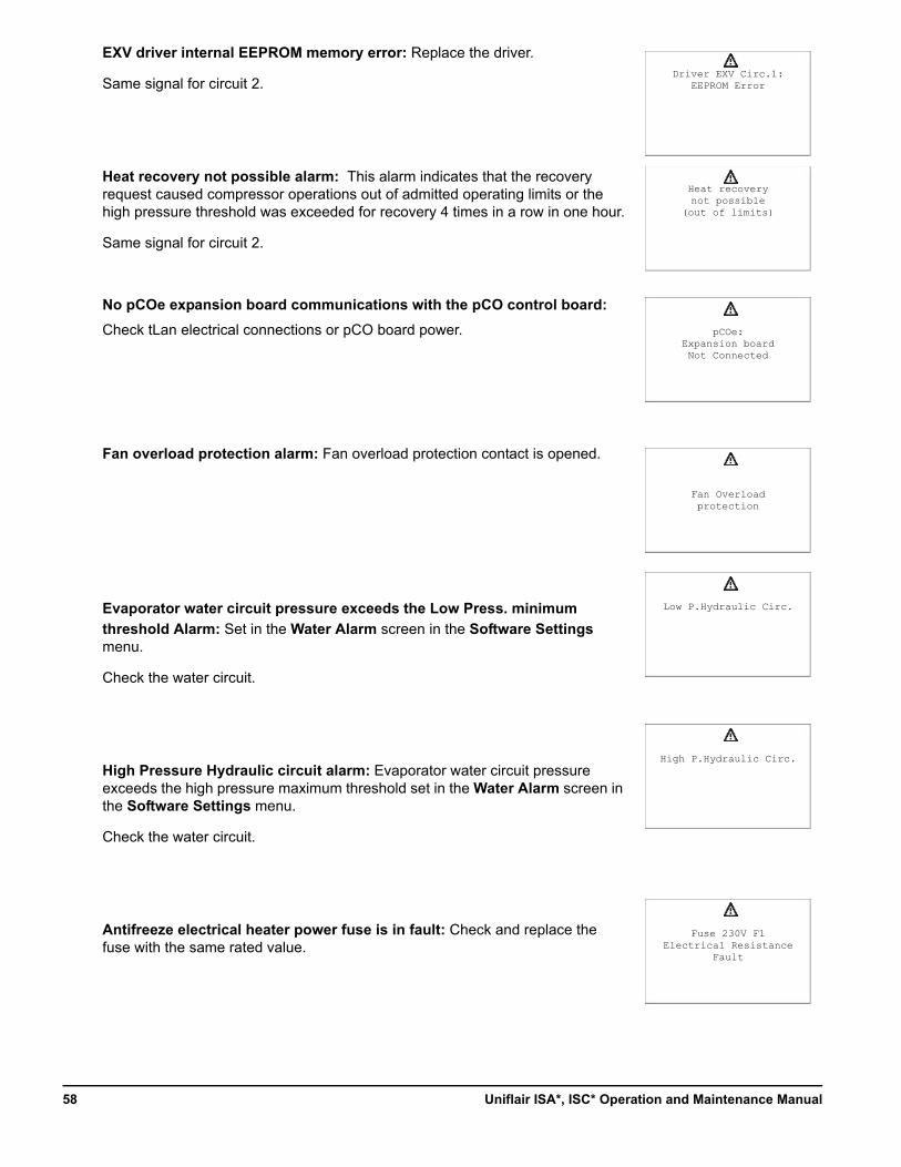
EXV driver internal EEPROM memory error: Replace the driver.
Same signal for circuit 2.
Heat recovery not possible alarm: This alarm indicates that the recovery request caused compressor operations out of admitted operating limits or the high pressure threshold was exceeded for recovery 4 times in a row in one hour.
Same signal for circuit 2.
No pCOe expansion board communications with the pCO control board:
Check tLan electrical connections or pCO board power.
Fan overload protection alarm: Fan overload protection contact is opened.
Evaporator water circuit pressure exceeds the Low Press. minimum
threshold Alarm: Set in the Water Alarm screen in the Software Settings menu.
Check the water circuit.
High Pressure Hydraulic circuit alarm: Evaporator water circuit pressure exceeds the high pressure maximum threshold set in the Water Alarm screen in the Software Settings menu.
Check the water circuit.
Antifreeze electrical heater power fuse is in fault: Check and replace the fuse with the same rated value.
Driver EXV Circ.1:EEPROM Error
Heat recoverynot possible
(out of limits)
pCOe:Expansion boardNot Connected
Fan Overloadprotection
Low P.Hydraulic Circ.
High P.Hydraulic Circ.
Fuse 230V F1Electrical Resistance
Fault
Uniflair ISA*, ISC* Operation and Maintenance Manual58
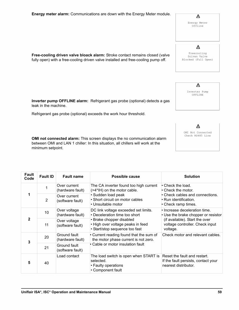
Energy meter alarm: Communications are down with the Energy Meter module.
Free-cooling driven valve bloack alarm: Stroke contact remains closed (valve fully open) with a free-cooling driven valve installed and free-cooling pump off.
Inverter pump OFFLINE alarm: Refrigerant gas probe (optional) detects a gas leak in the machine.
Refrigerant gas probe (optional) exceeds the work hour threshold.
OMI not connected alarm: This screen displays the no communication alarm between OMI and LAN 1 chiller: In this situation, all chillers will work at the minimum setpoint.
Fault Code Fault ID Fault name Possible cause Solution
1
1Over current (hardware fault)
The CA inverter found too high current (>4*IH) on the motor cable.• Sudden load peak• Short circuit on motor cables• Unsuitable motor
• Check the load.• Check the motor.• Check cables and connections.• Run identification.• Check ramp times.
2Over current (software fault)
2
10Over voltage(hardware fault)
DC link voltage exceeded set limits.• Deceleration time too short• Brake chopper disabled• High over voltage peaks in feed• Start/stop sequence too fast
• Increase deceleration time.• Use the brake chopper or resistor
(if available). Start the over voltage controller. Check input voltage.
11Over voltage (software fault)
320
Ground fault (hardware fault)
• Current reading found that the sum of the motor phase current is not zero.
• Cable or motor insulation fault
Check motor and relevant cables.
21Ground fault (software fault)
5 40
Load contact The load switch is open when START is selected.• Faulty operations• Component fault
Reset the fault and restart. If the fault persists, contact your nearest distributor.
Energy MeterOffline
FreecoolingDriven Valve
Blocked (Full Open)
Inverter PumpOFFLINE
OMI Not ConnectedCheck RS485 Line
59Uniflair ISA*, ISC* Operation and Maintenance Manual
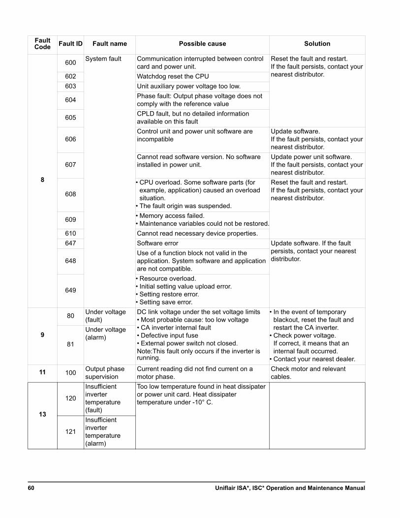
Fault Code Fault ID Fault name Possible cause Solution
8
600System fault Communication interrupted between control
card and power unit.Reset the fault and restart. If the fault persists, contact your nearest distributor.602 Watchdog reset the CPU
603 Unit auxiliary power voltage too low.
604Phase fault: Output phase voltage does not comply with the reference value
605CPLD fault, but no detailed information available on this fault
606Control unit and power unit software are incompatible
Update software. If the fault persists, contact your nearest distributor.
607Cannot read software version. No software installed in power unit.
Update power unit software. If the fault persists, contact your nearest distributor.
608
• CPU overload. Some software parts (for example, application) caused an overload situation.
• The fault origin was suspended.
Reset the fault and restart.If the fault persists, contact your nearest distributor.
609• Memory access failed.• Maintenance variables could not be restored.
610 Cannot read necessary device properties.
647 Software error Update software. If the fault persists, contact your nearest distributor.648
Use of a function block not valid in the application. System software and application are not compatible.
649
• Resource overload. • Initial setting value upload error.• Setting restore error.• Setting save error.
9
80Under voltage (fault)
DC link voltage under the set voltage limits• Most probable cause: too low voltage• CA inverter internal fault• Defective input fuse• External power switch not closed.Note:This fault only occurs if the inverter is running.
• In the event of temporary blackout, reset the fault and restart the CA inverter.
• Check power voltage. If correct, it means that an internal fault occurred.
• Contact your nearest dealer.
81
Under voltage (alarm)
11 100Output phase supervision
Current reading did not find current on a motor phase.
Check motor and relevant cables.
13
120
Insufficient inverter temperature (fault)
Too low temperature found in heat dissipater or power unit card. Heat dissipater temperature under -10° C.
121
Insufficient inverter temperature (alarm)
Uniflair ISA*, ISC* Operation and Maintenance Manual60
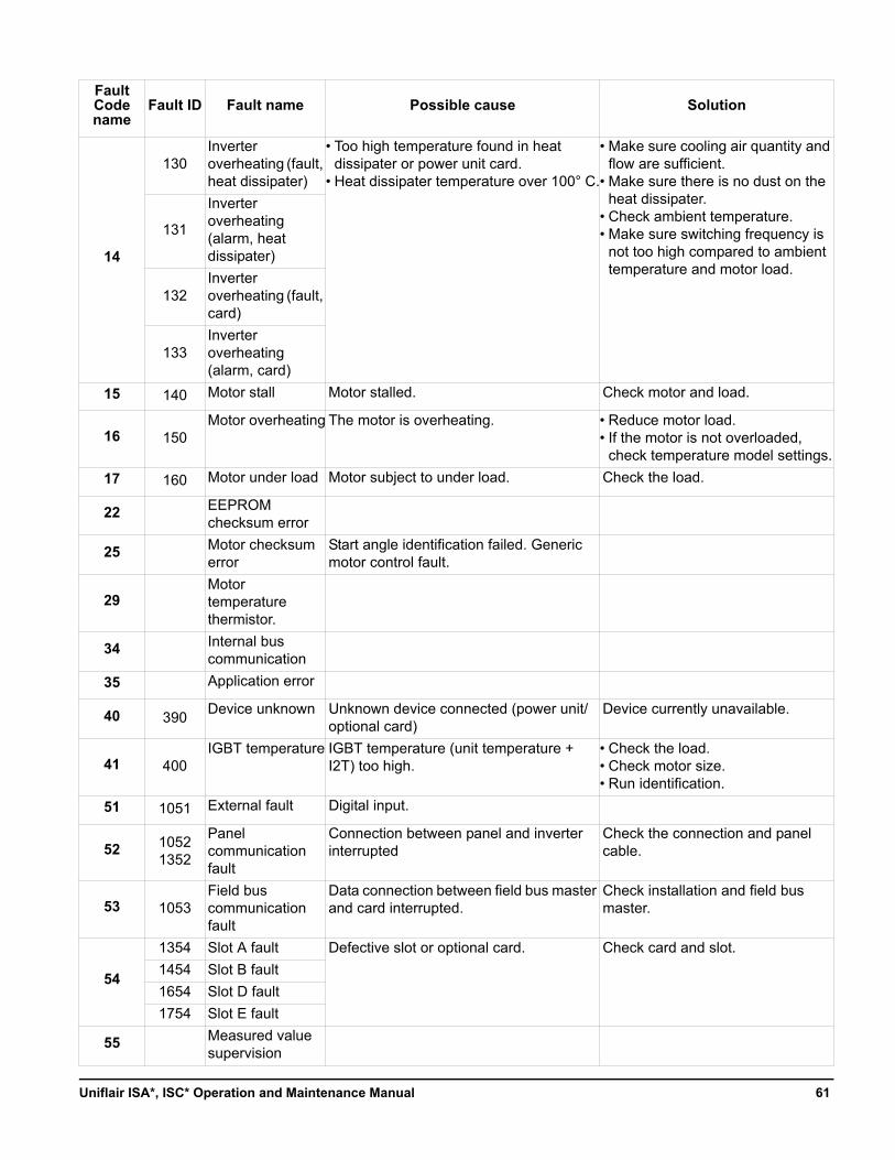
Fault Code name
Fault ID Fault name Possible cause Solution
14
130Inverter overheating (fault, heat dissipater)
• Too high temperature found in heat dissipater or power unit card.
• Heat dissipater temperature over 100° C.
• Make sure cooling air quantity and flow are sufficient.
• Make sure there is no dust on the heat dissipater.
• Check ambient temperature.• Make sure switching frequency is
not too high compared to ambient temperature and motor load.
131
Inverter overheating (alarm, heat dissipater)
132Inverter overheating (fault, card)
133Inverter overheating (alarm, card)
15 140 Motor stall Motor stalled. Check motor and load.
16 150Motor overheating The motor is overheating. • Reduce motor load.
• If the motor is not overloaded, check temperature model settings.
17 160 Motor under load Motor subject to under load. Check the load.
22 EEPROM checksum error
25 Motor checksum error
Start angle identification failed. Generic motor control fault.
29Motor temperature thermistor.
34 Internal bus communication
35 Application error
40 390Device unknown Unknown device connected (power unit/
optional card)Device currently unavailable.
41 400IGBT temperature IGBT temperature (unit temperature +
I2T) too high.• Check the load.• Check motor size.• Run identification.
51 1051 External fault Digital input.
52 1052 1352
Panel communication fault
Connection between panel and inverter interrupted
Check the connection and panel cable.
53 1053Field bus communication fault
Data connection between field bus master and card interrupted.
Check installation and field bus master.
54
1354 Slot A fault Defective slot or optional card. Check card and slot.
1454 Slot B fault
1654 Slot D fault
1754 Slot E fault
55 Measured value supervision
61Uniflair ISA*, ISC* Operation and Maintenance Manual
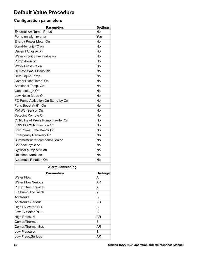
Default Value Procedure
Configuration parameters
Parameters SettingsExternal low Temp. Probe No
Pump on with inverter Yes
Energy Power Meter On No
Stand-by unit FC on No
Driven FC valve on No
Water circuit driven valve on No
Pump down on No
Water Pressure on No
Remote Wat. T.Sens. on No
Refr. Liquid Temp. No
Compr.Disch.Temp. On No
Additional Temp. On No
Gas Leakage On No
Low Noise Mode On No
FC Pump Activation On Stand-by On No
Fans Boost Antifr. On No
Ref.Wat.Sensor On No
Setpoint Remote On No
CTRL Head Press Pump Inverter On No
LOW POWER Function On No
Low Power Time Bands On No
Emergency Recovery On No
Summer/Winter compensation on No
Set-back cycle on No
Cyclical pump start on No
Unit time bands on No
Automatic Rotation On No
Alarm Addressing
Parameters SettingsWater Flow A
Water Flow Serious AR
Pump Therm.Switch A
FC Pump Th-Switch A
Antifreeze B
Antifreeze Serious AR
High Ev.Water IN T. B
Low Ev.Water IN T. B
High Pressure AR
Compr.Thermal B
Compr.Thermal Ser. AR
Low Pressure B
Low Press.Serious AR
Uniflair ISA*, ISC* Operation and Maintenance Manual62
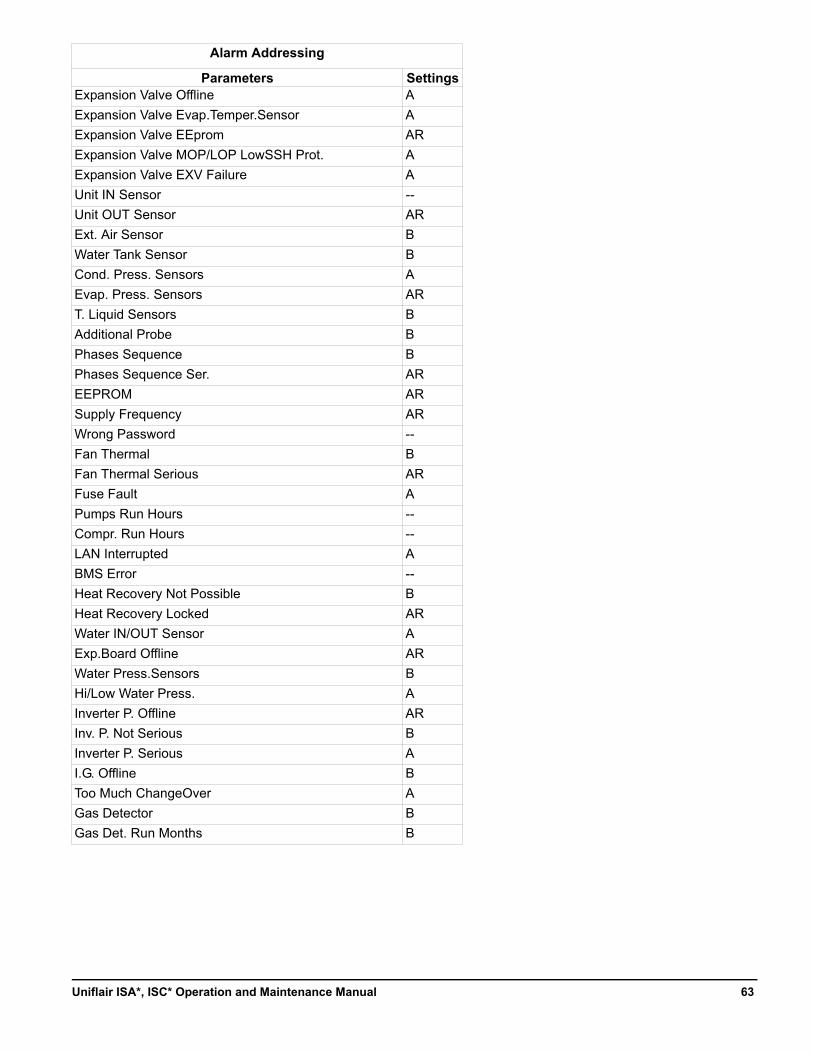
Expansion Valve Offline A
Expansion Valve Evap.Temper.Sensor A
Expansion Valve EEprom AR
Expansion Valve MOP/LOP LowSSH Prot. A
Expansion Valve EXV Failure A
Unit IN Sensor --
Unit OUT Sensor AR
Ext. Air Sensor B
Water Tank Sensor B
Cond. Press. Sensors A
Evap. Press. Sensors AR
T. Liquid Sensors B
Additional Probe B
Phases Sequence B
Phases Sequence Ser. AR
EEPROM AR
Supply Frequency AR
Wrong Password --
Fan Thermal B
Fan Thermal Serious AR
Fuse Fault A
Pumps Run Hours --
Compr. Run Hours --
LAN Interrupted A
BMS Error --
Heat Recovery Not Possible B
Heat Recovery Locked AR
Water IN/OUT Sensor A
Exp.Board Offline AR
Water Press.Sensors B
Hi/Low Water Press. A
Inverter P. Offline AR
Inv. P. Not Serious B
Inverter P. Serious A
I.G. Offline B
Too Much ChangeOver A
Gas Detector B
Gas Det. Run Months B
Alarm Addressing
Parameters Settings
63Uniflair ISA*, ISC* Operation and Maintenance Manual
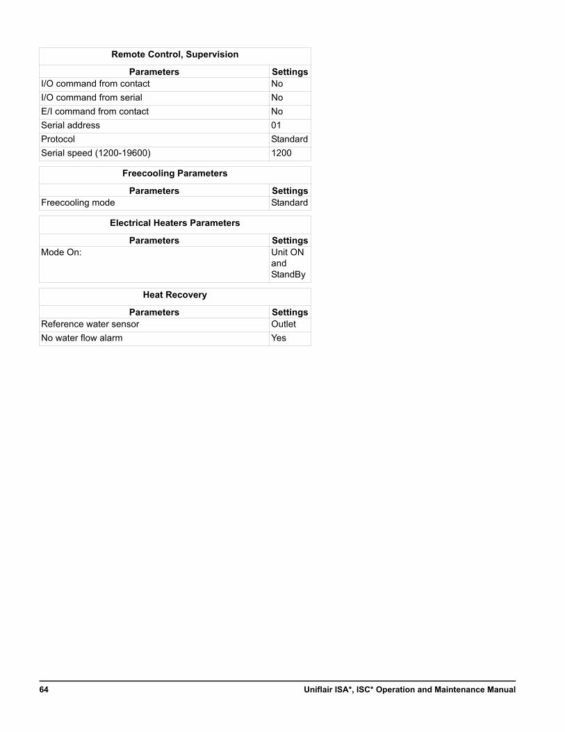
Remote Control, Supervision
Parameters SettingsI/O command from contact No
I/O command from serial No
E/I command from contact No
Serial address 01
Protocol Standard
Serial speed (1200-19600) 1200
Freecooling Parameters
Parameters SettingsFreecooling mode Standard
Electrical Heaters Parameters
Parameters SettingsMode On: Unit ON
and StandBy
Heat Recovery
Parameters SettingsReference water sensor Outlet
No water flow alarm Yes
Uniflair ISA*, ISC* Operation and Maintenance Manual64
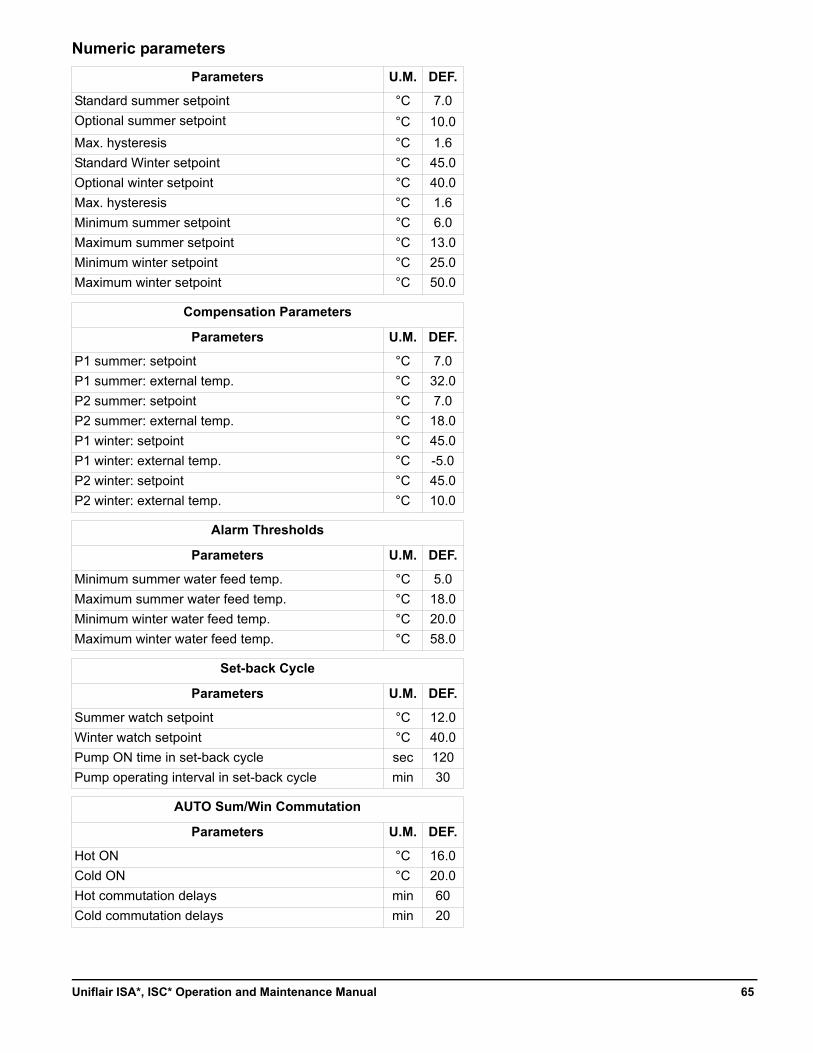
Numeric parameters
Parameters U.M. DEF.
Standard summer setpoint °C 7.0
Optional summer setpoint °C 10.0
Max. hysteresis °C 1.6
Standard Winter setpoint °C 45.0
Optional winter setpoint °C 40.0
Max. hysteresis °C 1.6
Minimum summer setpoint °C 6.0
Maximum summer setpoint °C 13.0
Minimum winter setpoint °C 25.0
Maximum winter setpoint °C 50.0
Compensation Parameters
Parameters U.M. DEF.
P1 summer: setpoint °C 7.0
P1 summer: external temp. °C 32.0
P2 summer: setpoint °C 7.0
P2 summer: external temp. °C 18.0
P1 winter: setpoint °C 45.0
P1 winter: external temp. °C -5.0
P2 winter: setpoint °C 45.0
P2 winter: external temp. °C 10.0
Alarm Thresholds
Parameters U.M. DEF.
Minimum summer water feed temp. °C 5.0
Maximum summer water feed temp. °C 18.0
Minimum winter water feed temp. °C 20.0
Maximum winter water feed temp. °C 58.0
Set-back Cycle
Parameters U.M. DEF.
Summer watch setpoint °C 12.0
Winter watch setpoint °C 40.0
Pump ON time in set-back cycle sec 120
Pump operating interval in set-back cycle min 30
AUTO Sum/Win Commutation
Parameters U.M. DEF.
Hot ON °C 16.0
Cold ON °C 20.0
Hot commutation delays min 60
Cold commutation delays min 20
65Uniflair ISA*, ISC* Operation and Maintenance Manual
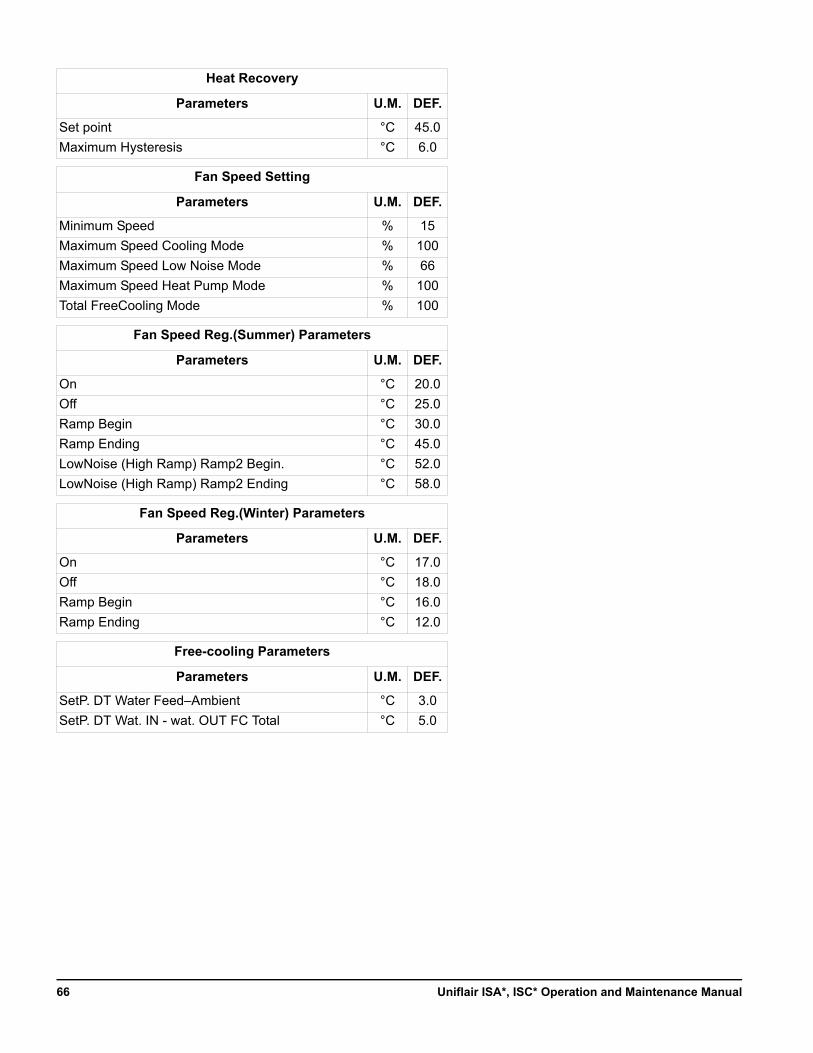
Heat Recovery
Parameters U.M. DEF.
Set point °C 45.0
Maximum Hysteresis °C 6.0
Fan Speed Setting
Parameters U.M. DEF.
Minimum Speed % 15
Maximum Speed Cooling Mode % 100
Maximum Speed Low Noise Mode % 66
Maximum Speed Heat Pump Mode % 100
Total FreeCooling Mode % 100
Fan Speed Reg.(Summer) Parameters
Parameters U.M. DEF.
On °C 20.0
Off °C 25.0
Ramp Begin °C 30.0
Ramp Ending °C 45.0
LowNoise (High Ramp) Ramp2 Begin. °C 52.0
LowNoise (High Ramp) Ramp2 Ending °C 58.0
Fan Speed Reg.(Winter) Parameters
Parameters U.M. DEF.
On °C 17.0
Off °C 18.0
Ramp Begin °C 16.0
Ramp Ending °C 12.0
Free-cooling Parameters
Parameters U.M. DEF.
SetP. DT Water Feed–Ambient °C 3.0
SetP. DT Wat. IN - wat. OUT FC Total °C 5.0
Uniflair ISA*, ISC* Operation and Maintenance Manual66
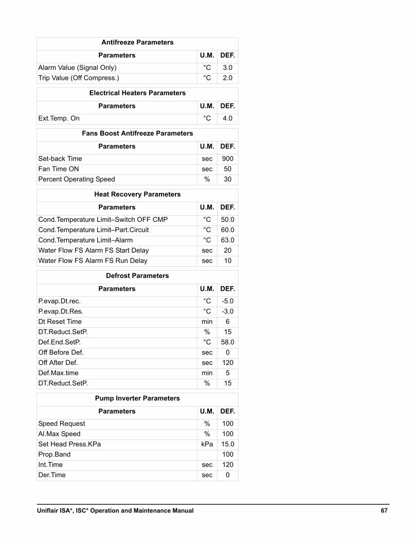
Antifreeze Parameters
Parameters U.M. DEF.
Alarm Value (Signal Only) °C 3.0
Trip Value (Off Compress.) °C 2.0
Electrical Heaters Parameters
Parameters U.M. DEF.
Ext.Temp. On °C 4.0
Fans Boost Antifreeze Parameters
Parameters U.M. DEF.
Set-back Time sec 900
Fan Time ON sec 50
Percent Operating Speed % 30
Heat Recovery Parameters
Parameters U.M. DEF.
Cond.Temperature Limit–Switch OFF CMP °C 50.0
Cond.Temperature Limit–Part.Circuit °C 60.0
Cond.Temperature Limit–Alarm °C 63.0
Water Flow FS Alarm FS Start Delay sec 20
Water Flow FS Alarm FS Run Delay sec 10
Defrost Parameters
Parameters U.M. DEF.
P.evap.Dt.rec. °C -5.0
P.evap.Dt.Res. °C -3.0
Dt Reset Time min 6
DT.Reduct.SetP. % 15
Def.End.SetP. °C 58.0
Off Before Def. sec 0
Off After Def. sec 120
Def.Max.time min 5
DT.Reduct.SetP. % 15
Pump Inverter Parameters
Parameters U.M. DEF.
Speed Request % 100
Al.Max Speed % 100
Set Head Press.KPa kPa 15.0
Prop.Band 100
Int.Time sec 120
Der.Time sec 0
67Uniflair ISA*, ISC* Operation and Maintenance Manual
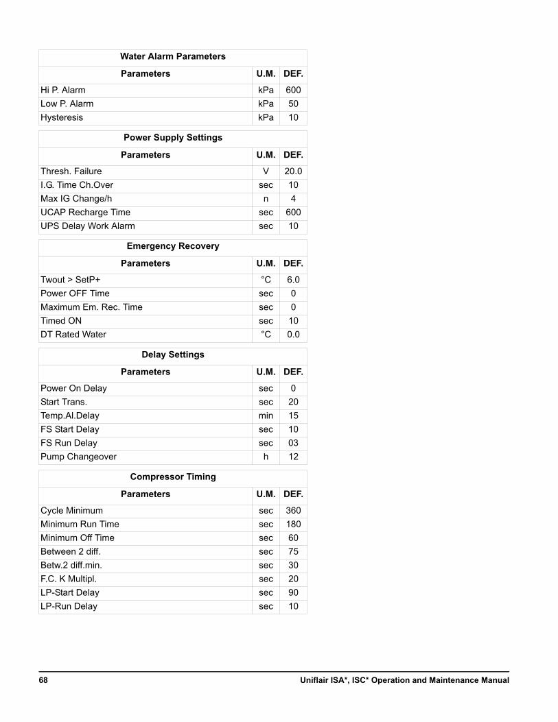
Water Alarm Parameters
Parameters U.M. DEF.
Hi P. Alarm kPa 600
Low P. Alarm kPa 50
Hysteresis kPa 10
Power Supply Settings
Parameters U.M. DEF.
Thresh. Failure V 20.0
I.G. Time Ch.Over sec 10
Max IG Change/h n 4
UCAP Recharge Time sec 600
UPS Delay Work Alarm sec 10
Emergency Recovery
Parameters U.M. DEF.
Twout > SetP+ °C 6.0
Power OFF Time sec 0
Maximum Em. Rec. Time sec 0
Timed ON sec 10
DT Rated Water °C 0.0
Delay Settings
Parameters U.M. DEF.
Power On Delay sec 0
Start Trans. sec 20
Temp.Al.Delay min 15
FS Start Delay sec 10
FS Run Delay sec 03
Pump Changeover h 12
Compressor Timing
Parameters U.M. DEF.
Cycle Minimum sec 360
Minimum Run Time sec 180
Minimum Off Time sec 60
Between 2 diff. sec 75
Betw.2 diff.min. sec 30
F.C. K Multipl. sec 20
LP-Start Delay sec 90
LP-Run Delay sec 10
Uniflair ISA*, ISC* Operation and Maintenance Manual68
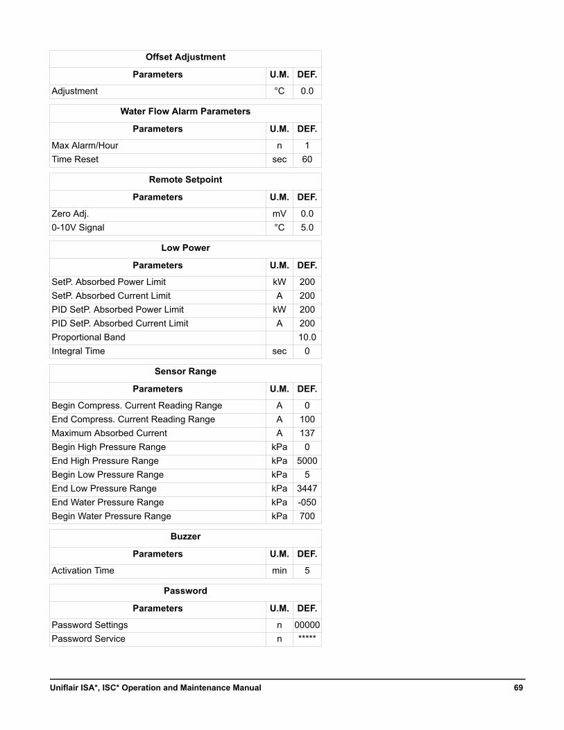
Offset Adjustment
Parameters U.M. DEF.
Adjustment °C 0.0
Water Flow Alarm Parameters
Parameters U.M. DEF.
Max Alarm/Hour n 1
Time Reset sec 60
Remote Setpoint
Parameters U.M. DEF.
Zero Adj. mV 0.0
0-10V Signal °C 5.0
Low Power
Parameters U.M. DEF.
SetP. Absorbed Power Limit kW 200
SetP. Absorbed Current Limit A 200
PID SetP. Absorbed Power Limit kW 200
PID SetP. Absorbed Current Limit A 200
Proportional Band 10.0
Integral Time sec 0
Sensor Range
Parameters U.M. DEF.
Begin Compress. Current Reading Range A 0
End Compress. Current Reading Range A 100
Maximum Absorbed Current A 137
Begin High Pressure Range kPa 0
End High Pressure Range kPa 5000
Begin Low Pressure Range kPa 5
End Low Pressure Range kPa 3447
End Water Pressure Range kPa -050
Begin Water Pressure Range kPa 700
Buzzer
Parameters U.M. DEF.
Activation Time min 5
Password
Parameters U.M. DEF.
Password Settings n 00000
Password Service n *****
69Uniflair ISA*, ISC* Operation and Maintenance Manual
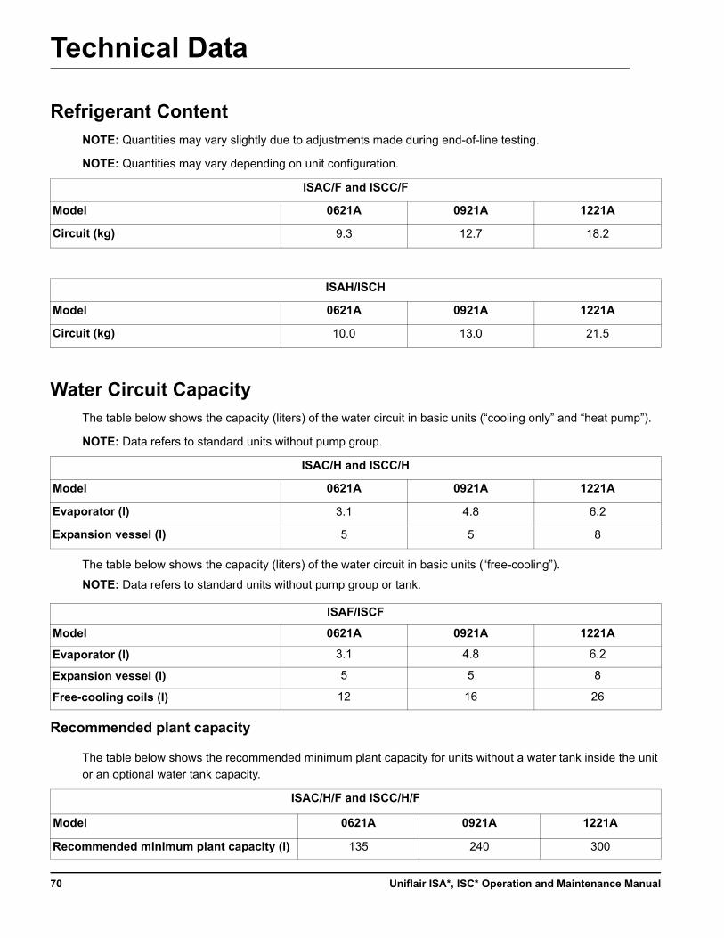
Technical Data
Refrigerant ContentNOTE: Quantities may vary slightly due to adjustments made during end-of-line testing.
NOTE: Quantities may vary depending on unit configuration.
Water Circuit CapacityThe table below shows the capacity (liters) of the water circuit in basic units (“cooling only” and “heat pump”).
NOTE: Data refers to standard units without pump group.
The table below shows the capacity (liters) of the water circuit in basic units (“free-cooling”).
NOTE: Data refers to standard units without pump group or tank.
Recommended plant capacity
The table below shows the recommended minimum plant capacity for units without a water tank inside the unit
or an optional water tank capacity.
ISAC/F and ISCC/F
Model 0621A 0921A 1221A
Circuit (kg) 9.3 12.7 18.2
ISAH/ISCH
Model 0621A 0921A 1221A
Circuit (kg) 10.0 13.0 21.5
ISAC/H and ISCC/H
Model 0621A 0921A 1221A
Evaporator (l) 3.1 4.8 6.2
Expansion vessel (l) 5 5 8
ISAF/ISCF
Model 0621A 0921A 1221A
Evaporator (l) 3.1 4.8 6.2
Expansion vessel (l) 5 5 8
Free-cooling coils (l) 12 16 26
ISAC/H/F and ISCC/H/F
Model 0621A 0921A 1221A
Recommended minimum plant capacity (l) 135 240 300
Uniflair ISA*, ISC* Operation and Maintenance Manual70
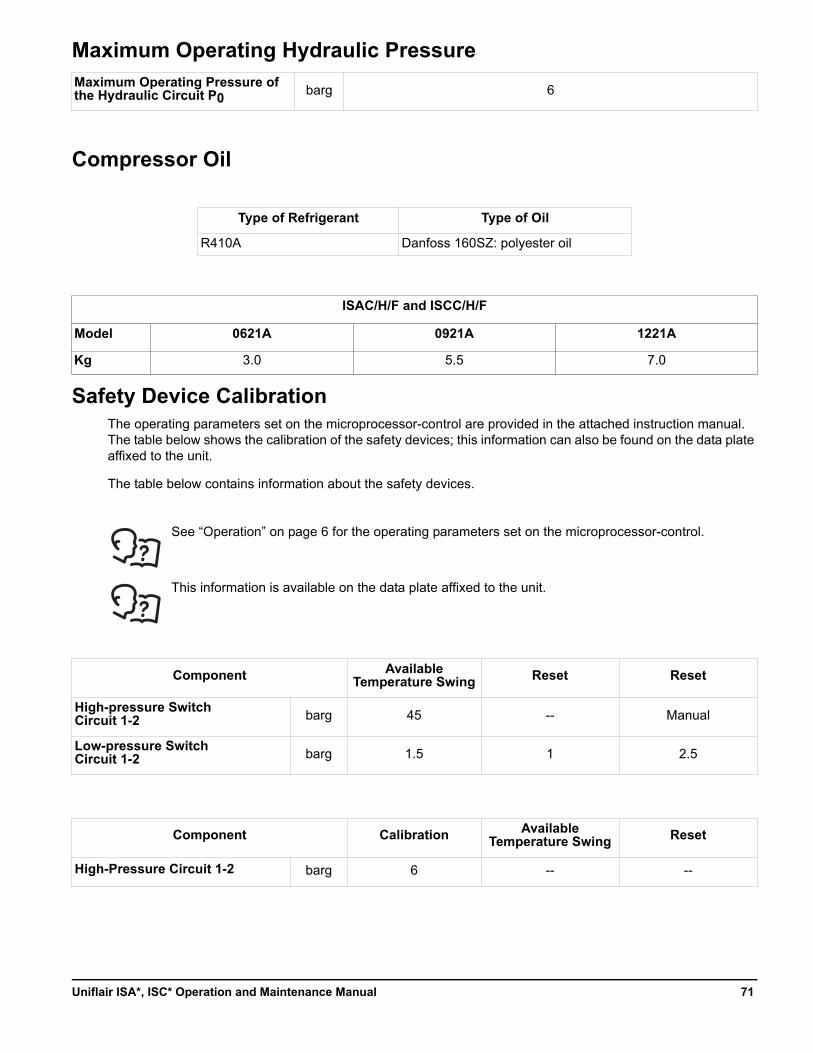
Maximum Operating Hydraulic Pressure
Compressor Oil
Safety Device CalibrationThe operating parameters set on the microprocessor-control are provided in the attached instruction manual. The table below shows the calibration of the safety devices; this information can also be found on the data plate affixed to the unit.
The table below contains information about the safety devices.
See “Operation” on page 6 for the operating parameters set on the microprocessor-control.
This information is available on the data plate affixed to the unit.
Maximum Operating Pressure of the Hydraulic Circuit P0
barg 6
Type of Refrigerant Type of Oil
R410A Danfoss 160SZ: polyester oil
ISAC/H/F and ISCC/H/F
Model 0621A 0921A 1221A
Kg 3.0 5.5 7.0
Component Available Temperature Swing Reset Reset
High-pressure SwitchCircuit 1-2 barg 45 -- Manual
Low-pressure Switch Circuit 1-2 barg 1.5 1 2.5
Component Calibration Available Temperature Swing Reset
High-Pressure Circuit 1-2 barg 6 -- --
71Uniflair ISA*, ISC* Operation and Maintenance Manual
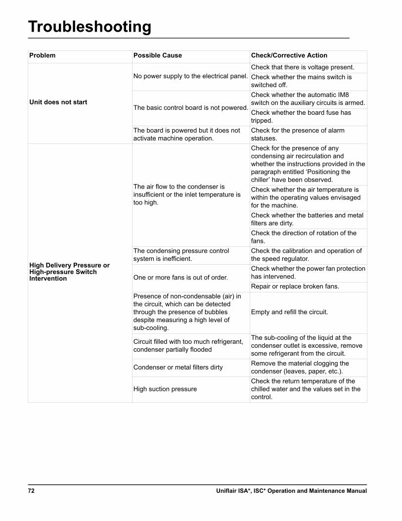
Troubleshooting
Problem Possible Cause Check/Corrective Action
Unit does not start
No power supply to the electrical panel.Check that there is voltage present.
Check whether the mains switch is switched off.
The basic control board is not powered.
Check whether the automatic IM8 switch on the auxiliary circuits is armed.
Check whether the board fuse has tripped.
The board is powered but it does not activate machine operation.
Check for the presence of alarm statuses.
High Delivery Pressure or High-pressure Switch Intervention
The air flow to the condenser is insufficient or the inlet temperature is too high.
Check for the presence of any condensing air recirculation and whether the instructions provided in the paragraph entitled ‘Positioning the chiller’ have been observed.
Check whether the air temperature is within the operating values envisaged for the machine.
Check whether the batteries and metal filters are dirty.
Check the direction of rotation of the fans.
The condensing pressure control system is inefficient.
Check the calibration and operation of the speed regulator.
One or more fans is out of order.Check whether the power fan protection has intervened.
Repair or replace broken fans.
Presence of non-condensable (air) in the circuit, which can be detected through the presence of bubbles despite measuring a high level of sub-cooling.
Empty and refill the circuit.
Circuit filled with too much refrigerant, condenser partially flooded
The sub-cooling of the liquid at the condenser outlet is excessive, remove some refrigerant from the circuit.
Condenser or metal filters dirtyRemove the material clogging the condenser (leaves, paper, etc.).
High suction pressureCheck the return temperature of the chilled water and the values set in the control.
Uniflair ISA*, ISC* Operation and Maintenance Manual72
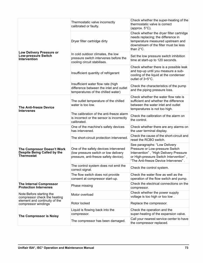
Low Delivery Pressure or Low-pressure Switch Intervention
Thermostatic valve incorrectly calibrated or faulty.
Check whether the super-heating of the thermostatic valve is correct (approx. 5°C).
Dryer filter cartridge dirty
Check whether the dryer filter cartridge needs replacing; the difference in temperature measured upstream and downstream of the filter must be less than 2°C.
In cold outdoor climates, the low pressure switch intervenes before the cooling circuit stabilises.
Set the low pressure switch inhibition time at start-up to 120 seconds.
Insufficient quantity of refrigerant
Check whether there is a possible leak and top-up until you measure a sub-cooling of the liquid at the condenser outlet of 3÷5°C.
Insufficient water flow rate (high difference between the inlet and outlet temperatures of the chilled water)
Check the characteristics of the pump and the piping pressure loss.
The Anti-freeze Device Intervenes
The outlet temperature of the chilled water is too low.
Check whether the water flow rate is sufficient and whether the difference between the water inlet and outlet temperatures is not too high.
The calibration of the anti-freeze alarm is incorrect or the sensor is incorrectly calibrated.
Check the calibration of the alarm on the control.
The Compresor Doesn’t Work Despite Being Called by the Thermostat
One of the machine's safety devices has intervened.
Check whether there are any alarms on the user terminal display.
The short-circuit protection intervened.Check the cause of the short-circuit and reset the RCBO switch.
One of the safety devices intervened (low pressure switch or low delivery pressure, anti-freeze safety device).
See paragraphs: “Low Delivery Pressure or Low-pressure Switch Intervention” , “High Delivery Pressure or High-pressure Switch Intervention” , “The Anti-freeze Device Intervenes” .
The control system does not emit the correct signal.
Check the control system.
The flow switch does not provide consent at compressor start-up.
Check the water flow as well as the operation of the flow switch and pump.
The Internal Compressor Protection Intervenes
Note:Before starting the compressor check the heating element and continuity of the compressor windings
Phase missingCheck the electrical connections on the compressor.
Motor overload Check whether the power supply voltage is too high or too low .
Rotor locked Replace the compressor.
The Compressor is Noisy
Liquid is flowing back into the compressor.
Check the operation and the super-heating of the expansion valve.
The compressor has been damaged.Call your nearest service center to have the compressor replaced.
73Uniflair ISA*, ISC* Operation and Maintenance Manual
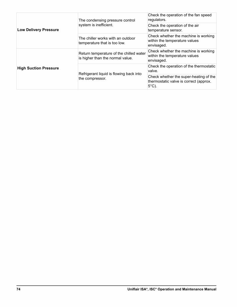
Low Delivery Pressure
The condensing pressure control system is inefficient.
Check the operation of the fan speed regulators.
Check the operation of the air temperature sensor.
The chiller works with an outdoor temperature that is too low.
Check whether the machine is working within the temperature values envisaged.
High Suction Pressure
Return temperature of the chilled water is higher than the normal value.
Check whether the machine is working within the temperature values envisaged.
Refrigerant liquid is flowing back into the compressor.
Check the operation of the thermostatic valve.
Check whether the super-heating of the thermostatic valve is correct (approx. 5°C).
Uniflair ISA*, ISC* Operation and Maintenance Manual74
Default Values Update and Protocol Variables
In order to access the latest release of default values and get the protocol variables, check the Schneider Electric webcard portal.
The procedure for getting an account is the following:
1. Open Internet Explorer® browser (release 6.0 or later) and enter the following address: http://webcard-it.schneider-electric.com/activation.asp
2. Enter your personal mail address and company name, then click on Activation Code.You will automatically receive an email with your account details.
3. Open your Internet Explorer browser (release 6.0 or more) and enter the following address: http://webcard-it.schneider-electric.com/
4. Enter your login and password and access the reserved area to find the updated releases for default values and protocol variables.
75Uniflair ISA*, ISC* Operation and Maintenance Manual
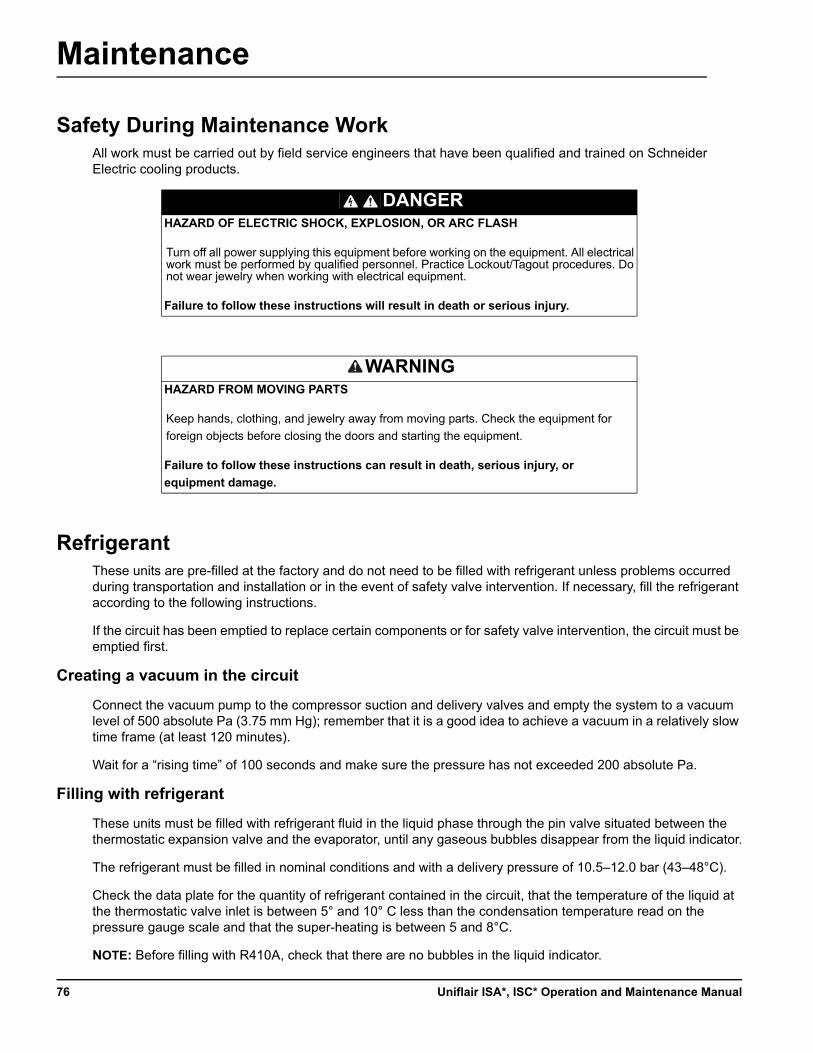
Maintenance
Safety During Maintenance WorkAll work must be carried out by field service engineers that have been qualified and trained on Schneider Electric cooling products.
RefrigerantThese units are pre-filled at the factory and do not need to be filled with refrigerant unless problems occurred during transportation and installation or in the event of safety valve intervention. If necessary, fill the refrigerant according to the following instructions.
If the circuit has been emptied to replace certain components or for safety valve intervention, the circuit must be emptied first.
Creating a vacuum in the circuit
Connect the vacuum pump to the compressor suction and delivery valves and empty the system to a vacuum level of 500 absolute Pa (3.75 mm Hg); remember that it is a good idea to achieve a vacuum in a relatively slow time frame (at least 120 minutes).
Wait for a “rising time” of 100 seconds and make sure the pressure has not exceeded 200 absolute Pa.
Filling with refrigerant
These units must be filled with refrigerant fluid in the liquid phase through the pin valve situated between the thermostatic expansion valve and the evaporator, until any gaseous bubbles disappear from the liquid indicator.
The refrigerant must be filled in nominal conditions and with a delivery pressure of 10.5–12.0 bar (43–48°C).
Check the data plate for the quantity of refrigerant contained in the circuit, that the temperature of the liquid at the thermostatic valve inlet is between 5° and 10° C less than the condensation temperature read on the pressure gauge scale and that the super-heating is between 5 and 8°C.
NOTE: Before filling with R410A, check that there are no bubbles in the liquid indicator.
DANGERHAZARD OF ELECTRIC SHOCK, EXPLOSION, OR ARC FLASH
Turn off all power supplying this equipment before working on the equipment. All electrical work must be performed by qualified personnel. Practice Lockout/Tagout procedures. Do not wear jewelry when working with electrical equipment.
Failure to follow these instructions will result in death or serious injury.
WARNINGHAZARD FROM MOVING PARTS
Keep hands, clothing, and jewelry away from moving parts. Check the equipment for
foreign objects before closing the doors and starting the equipment.
Failure to follow these instructions can result in death, serious injury, or
equipment damage.
Uniflair ISA*, ISC* Operation and Maintenance Manual76
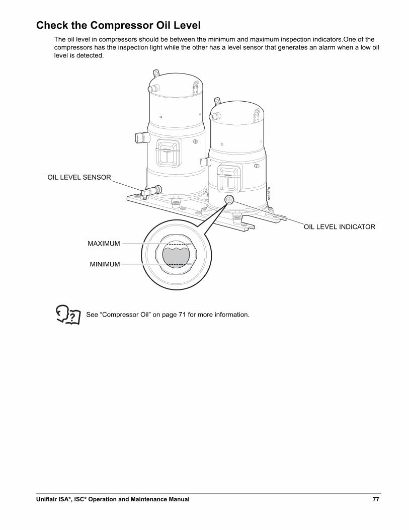
Check the Compressor Oil LevelThe oil level in compressors should be between the minimum and maximum inspection indicators.One of the compressors has the inspection light while the other has a level sensor that generates an alarm when a low oil level is detected.
See “Compressor Oil” on page 71 for more information.
na58
87a
MINIMUM
MAXIMUM
OIL LEVEL SENSOR
OIL LEVEL INDICATOR
77Uniflair ISA*, ISC* Operation and Maintenance Manual
Double Power Supply
When the unit is fitted with a double power supply managed by an automatic switch-over driven switch, the switch does not have external operation.
IMPORTANT: Before opening the front panel to access the electrical panel, stop the unit from the display interface according to the instructions provided in the Operation and Maintenance Manual.
The compressor timings must be observed during the swap between the two electricity supply lines. In the absence of voltage on line A (main electricity supply), line B (emergency line) must be kept active for at least six minutes before switching back to line A when the voltage returns. Prepare a dedicated device (under the responsibility of the customer) at the place of installation.
Opening the front panel with the unit in operation causes a micro-switch to trip, which immediately stops the unit. In this case, the switch-off timings envisaged by the control software will not be observed.
With the machine stopped and with the electrical panel door open, there is only voltage upstream of the disconnecting switch. In the event of maintenance work, to have voltage throughout the electrical panel, you will need to set the key operated selector switch to ON; depending on the model, this key-operated selector switch may be installed on the left-hand post of the unit or underneath the electrical panel.
IMPORTANT: Once the maintenance work has been completed, restore automatic operation.
DANGERHAZARD OF ELECTRIC SHOCK, EXPLOSION, OR ARC FLASH
• Apply appropriate personal protective equipment (PPE) and follow safe electrical work practices. See NFPA 70E or CSA Z462.
• This equipment must be installed and serviced by qualified personnel only.
• Turn off all power supplying this equipment before working on or inside the equipment.
• Always use a properly rated voltage sensing device to confirm power is off.
• Replace all devices, doors, and covers before turning on power to this equipment.
Failure to follow these instructions will result in death or serious injury.
NOTICEHAZARD TO EQUIPMENT
The compressor timings must be observed during the swap between the two power supply lines.
Failure to follow these instructions can result in equipment damage.
NOTICEHAZARD TO EQUIPMENT
Only use the selector switch for maintenance work. When completed, restore automatic operation.
Failure to follow these instructions can result in equipment damage.
Uniflair ISA*, ISC* Operation and Maintenance Manual78
Low External Air Temperature
Units with free-cooling
Air-cooled water chillers with free-cooling systems must be filled with an anti-freeze mixture.
Units without free-cooling
Drain all water from the system before the winter season to avoid freezing. In periods when the outdoor temperature falls below 0°C, empty the unit in order to avoid serious damage caused by the formation of ice. This precaution is not necessary if the unit is filled with a suitable anti-freeze mixture.
If the unit is equipped with an optional heating cable, it must be turned off without disconnecting the main power supply.
Scheduled Maintenance Guidelines
Quarterly ChecksPerform the following checks every three months:
NOTICEHAZARD TO PERSONNEL
Where a winter shut-down is envisaged, you need to empty out the hydraulic circuit and add the necessary quantity of glycol to any water remaining inside the machine.
Failure to follow these instructions can result in equipment damage.
NOTICEHAZARD TO PERSONNEL
Periodic inspection of the free-cooling hoses (if equipped) for leaks and potential problems is recommended.
Failure to follow these instructions can result in equipment damage.
Check the mains voltage.
Check the alarm status .
Check the operating temperatures and pressures.
Check the local and/or remote control operation .
Check and possibly clean the condensation, free-cooling battery/ies and any metal pre-filters.
79Uniflair ISA*, ISC* Operation and Maintenance Manual
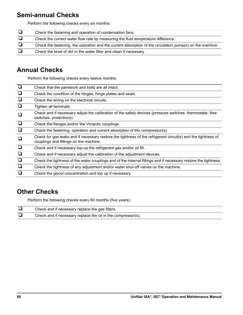
Semi-annual ChecksPerform the following checks every six months:
Annual ChecksPerform the following checks every twelve months:
Other ChecksPerform the following checks every 60 months (five years):
Check the fastening and operation of condensation fans.
Check the correct water flow rate by measuring the fluid temperature difference.
Check the fastening, the operation and the current absorption of the circulation pump(s) on the machine.
Check the level of dirt in the water filter and clean if necessary.
Check that the paintwork and bolts are all intact.
Check the condition of the hinges, hinge plates and seals.
Check the wiring on the electrical circuits.
Tighten all terminals.
Check and if necessary adjust the calibration of the safety devices (pressure switches, thermostats, flow switches, protections).
Check the flanges and/or the Victaulic couplings.
Check the fastening, operation and current absorption of the compressor(s).
Check for gas leaks and if necessary restore the tightness of the refrigerant circuit(s) and the tightness of couplings and fittings on the machine.
Check and if necessary top-up the refrigerant gas and/or oil fill.
Check and if necessary adjust the calibration of the adjustment devices.
Check the tightness of the water couplings and of the internal fittings and if necessary restore the tightness.
Check the tightness of any adjustment and/or water shut-off valves on the machine.
Check the glycol concentration and top up if necessary.
Check and if necessary replace the gas filters.
Check and if necessary replace the oil in the compressor(s).
Uniflair ISA*, ISC* Operation and Maintenance Manual80


Worldwide Customer SupportCustomer support for this or any other product is available at no charge in any of the following ways:
• Visit the Schneider Electric Web site to access documents in the Schneider Electric Knowledge Base and to submit customer support requests.
– www.schneider-electric.com (Corporate Headquarters)Connect to localized Schneider Electric Web sites for specific countries, each of which provides customer support information.
– www.schneider-electric.com/support/Global support searching Schneider Electric Knowledge Base and using e-support.
• Contact the Schneider Electric Customer Support Center by telephone or e-mail.
– Local, country-specific centers: go to www.schneider-electric.com > Support > Operations around the world for contact information.
For information on how to obtain local customer support, contact the representative or other distributors from whom you purchased your product.
As standards, specifications, and designs change from time to time, please ask for confirmation of the information given in this publication.© 2016 Schneider Electric. All Rights Reserved.Uniflair and the Schneider Electric logo are trademarks owned by Schneider Electric Industries SAS S.A.S., or its affiliated companies. All other trademarks are the property of their respective owners.
4/2016990-9874-00106MC0104@00B0120