operation manual nc300 - deltaww.com · operation manual nc300 revision december, 2015 i table of...
TRANSCRIPT


Operation Manual NC300
Revision December, 2015 i
Table of content Chapter 1: Table of group menu
1.1 Table of system group menu ......................................................................... 1-1
1.2 Primary control panel function keys .............................................................. 1-10
1.3 Secondary control panel function keys .......................................................... 1-12
Chapter 2: Table of function groups
2.1 Auto mode (AUTO) ........................................................................................ 2-1
2.2 Program Edit mode (EDIT) ............................................................................ 2-1
2.3 Manual input mode (MDI) .............................................................................. 2-1
2.4 Hand wheel feeding mode (MPG) ................................................................. 2-1
2.5 Jog feeding mode (JOG) ............................................................................... 2-2
2.6 Home mode (HOME) ..................................................................................... 2-2
2.7 Group screen overview .................................................................................. 2-2
Chapter 3: POS group
3.1 Absolute coordinates ..................................................................................... 3-1
3.2 Relative coordinates ...................................................................................... 3-2
3.3 Mechanical coordinates ............................................................................... 3-3
Chapter 4: PRG group
4.1 Network setting .............................................................................................. 4-2
4.2 Add (create new file) .................................................................................... 4-8
4.3 Copy .............................................................................................................. 4-9
4.4 Paste ............................................................................................................. 4-10
4.5 Delete (for files and folders) .......................................................................... 4-11
4.6 Select/Deselect multiple files ......................................................................... 4-12
4.7 Rename ......................................................................................................... 4-15
4.8 Create directory (add folder) .......................................................................... 4-16

NC300 Operation Manual
ii Revision December, 2015
4.9 File searching ................................................................................................ 4-17
4.10 File merge ..................................................................................................... 4-18
4.11 Sequencing ................................................................................................... 4-19
4.12 Convert DXF files .......................................................................................... 4-20
4.13 Macro file ...................................................................................................... 4-21
4.14 File editing ..................................................................................................... 4-21
4.14.1 Search by line number ......................................................................... 4-22
4.14.2 Search by strings ................................................................................. 4-23
4.14.3 Block starting/ending point ................................................................ 4-25
4.14.4 Delete (lines and blocks) ..................................................................... 4-26
4.14.5 Copy and paste (line and block) .......................................................... 4-26
4.14.6 Undo .................................................................................................... 4-27
4.15 Other mode functions .................................................................................. 4-28
Chapter 5: OFS group
5.1 Coordinates setting ..................................................................................... 5-1
5.1.1 Auto setting ......................................................................................... 5-2
5.1.2 Absolute input ..................................................................................... 5-7
5.1.3 Incremental input ................................................................................. 5-9
5.1.4 Rectangle center ................................................................................. 5-10
5.1.5 Circle center ........................................................................................ 5-12
5.2 Tool register ................................................................................................... 5-14
5.3 Tool magazine register .................................................................................. 5-19
5.4 Macro variable ............................................................................................... 5-26
5.4.1 Local variable ...................................................................................... 5-26
5.4.2 Global variable .................................................................................... 5-27
5.4.3 Retaining variable ............................................................................... 5-27
5.4.4 Expanded variable .............................................................................. 5-28

Operation Manual NC300
Revision April, 2014 iii
Chapter 6: GRA group
6.1 Machining path .............................................................................................. 6-2
6.2 Machining preview ........................................................................................ 6-3
Chapter 7: ALM group
7.1 Alarm ............................................................................................................. 7-1
7.2 Alarm history (Message log) ......................................................................... 7-2
Chapter 8: DGN group
8.1 Machining information ................................................................................... 8-1
8.2 User variable ................................................................................................. 8-3
8.3 MLC .............................................................................................................. 8-4
8.3.1 Bit ........................................................................................................ 8-5
8.3.2 Register ............................................................................................... 8-6
8.3.3 Device monitoring ............................................................................... 8-7
8.3.4 Search line .......................................................................................... 8-9
8.3.5 Editor ................................................................................................... 8-9
8.3.6 Operation .......................................................................................... 8-12
8.4 System monitoring ........................................................................................ 8-14
8.4.1 Servo monitoring ................................................................................. 8-14
8.4.2 I/O monitoring .................................................................................... 8-14
8.4.3 Variable monitoring ............................................................................ 8-15
8.5 Password setting ........................................................................................... 8-18
8.5.1 System permission .............................................................................. 8-18
8.5.2 Equipment permission ......................................................................... 8-19
8.5.3 User permission .................................................................................. 8-23
8.5.4 Timed use ........................................................................................... 8-25
8.6 System information ....................................................................................... 8-29
8.7 Gain adjustment ............................................................................................ 8-31
8.8 Import ............................................................................................................ 8-36
8.9 Export ............................................................................................................ 8-38

NC300 Operation Manual
iv Revision December, 2015
8.10 Multi language download .............................................................................. 8-41
8.11 LOGO download ........................................................................................... 8-41
Chapter 9: PAR Group
9.1 Machining parameter .................................................................................. 9-1
9.2 Operation parameter ................................................................................... 9-2
9.3 Tool magazine parameter............................................................................ 9-3
9.4 Spindle parameter ....................................................................................... 9-4
9.5 Mechanical parameter ................................................................................ 9-5
9.6 Origin parameter ......................................................................................... 9-6
9.7 Network setup ............................................................................................. 9-7
9.8 Compensation parameter............................................................................ 9-8
9.9 System parameter ....................................................................................... 9-9
9.10 MLC setting ................................................................................................. 9-10
9.11 Graph parameter ......................................................................................... 9-11
9.12 Servo parameter ......................................................................................... 9-12
9.13 Channel setup ............................................................................................. 9-13
9.14 RIO setting .................................................................................................. 9-15
9.15 Search ........................................................................................................ 9-16
9.16 Parameter group ......................................................................................... 9-17
Chapter 10: SOFT group
10.1 Control panel ............................................................................................ 10-1
10.2 Factor regulation ........................................................................................ 10-3
10.3 Axis operation ........................................................................................... 10-4
Appendix A: Group function map

Chapter 1: Table of group menu NC300
Revision December, 2015 1-1
Chapter 1: Table of group menu
1.1 Table of system group menu
POS coordinates function
Layer 1 Layer 2 Layer 3 Layer 4 ABS - - -
REL (Connect to the physical axis to display the axial
clear function)
CLR ALL - - CLR X - - CLR Y - - CLR Z - - CLR A - - CLR B - - CLR C - -
MECH - - - [Program Edit mode]
PRG program function_file manager
Layer 1 Layer 2 Layer 3 Layer 4 COPY FILE - - -
PASTE - - - DEL (file/folder) - - -
SEL TOGL - - - CANCEL - - - SEL ALL - - -
SEQUENCE NAME - - SIZE - -
DATE - - NEW FILE - - - FOLDER - - - RENAME - - - FIND FILE - - -
MERGE - - - MACRO - - -
DXF - - -

NC300 Chapter 1: Table of group menu
1-2 Revision December, 2015
[Auto mode]
Layer 1 Layer 2 Layer 3 Layer 4 SF set - - - START RUN - -
FILE SCAN LOAD - - CLR - -
CLR ALL - - [JOG / MPG Feeding mode] program editing
Layer 1 Layer 2 Layer 3 Layer 4 SF set - - -
TEACH
RAPID - - LINEAR - -
ARC P1 - P2 - P3 -
PLANE SEL - DEL - -
SAVE - - NEW FILE - -
MECH / ABS - - [Manual Input mode] program editing
Layer 1 Layer 2 Layer 3 Layer 4 LOAD - - - SAVE - - -
CLEAR - - -
PRG program function_file editor
Layer 1 Layer 2 Layer 3 Layer 4
File editing
COPY - - PASTE - -
DEL - - UNDO - -
B START - - B END - - LABLE - -
STRING
NEXT - PREV -
REPLACE - REPLACE ALL -

Chapter 1: Table of group menu NC300
Revision December, 2015 1-3
[Homing mode] program editing Layer 1 Layer 2 Layer 3 Layer 4 SF set - - -
Offset (OFS) function
Layer 1 Layer 2 Layer 3 Layer 4
COORD
AUTO
CLR REL -
CLR ALL -
SET L -
SET L/2
1st POINT
2nd POINT
SET
SET P -
ABS - -
INC - -
SQUARE
X1 -
X2 -
Y1 -
Y2 -
SET -
SET Z -
CIRCLE
P1 -
P2 -
P3 -
SET -
SET Z -
CUTTER
ABS - -
INC - -
H SET - -
CLEAR
H/D -
WEAR -
LIFE -
ALL -
MAGA Maga 1
SET (※ jog mode) -
RST ALL(※ jog mode) -
LOCK (※ jog mode) -

NC300 Chapter 1: Table of group menu
1-4 Revision December, 2015
UNLOCK (※ jog mode)
-
Maga 2
SET (※ jog mode) -
RST ALL(※ jog mode) -
LOCK (※ jog mode) - UNLOCK (※ jog
mode) -
MACRO
LOCAL - -
GLOBAL - -
HOLD - - EXPAND - -
Graphic (GRA) function
Layer 1 Layer 2 Layer 3 Layer 4
CUTTING PATH
X-Y / Y-Z / X-Z / X-Y-Z
- -
CENTER - - ZOOM IN - -
ZOOM OUT - - DRAW - -
STOP DRAW - - UP - -
DOWN - - LEFT - -
RIGHT - -
CUTTING PREVIEW
(※Auto Mode)
X-Y / Y-Z / X-Z / X-Y-Z
- -
CENTER - - ZOOM IN - -
ZOOM OUT - - PREVIEW - -
CANCEL PREVIEW - - UP - -
DOWN - - LEFT - -
RIGHT - -
Alarm (ALM) function Layer 1 Layer 2 Layer 3 Layer 4 ALARM - - -
HISTORY CLR ALL - -

Chapter 1: Table of group menu NC300
Revision December, 2015 1-5
Diagnosis (DGN) function Layer 1 Layer 2 Layer 3 Layer 4
PROCESS SET - -
CLR TIME - - CLR NR - -
USER VAR
USER VAR
DEL - US DEC -
HEX - S DEC - FLOAT -
SYS VAR - -
M VAR
DEL - US DEC -
HEX - S DEC - FLOAT -
MLC
BIT
X - Y - M - A - T - C -
REG
T - C (16) - C (32) -
D - V - Z -
US DEC - HEX -
S DEC - FLOAT -
DEV MON
US DEC -
HEX -
S DEC -
FLOAT -
EDITOR (※edit mode)
LD - LDI - LDP - LDF - OUT - APP - — - | -
DEL V-LN - ADD LN - DEL LN -

NC300 Chapter 1: Table of group menu
1-6 Revision December, 2015
DEL - LABLE - TABLE -
SYMBOL
X Y M A T C D P I
DEL COPY PASTE
SAVE - IMPORT IMPORT
EXPORT EXPORT
NEW FILE JUMP TO - SELECT -
CUT - COPY - PASTE -
SET(※edit mode) ON - OFF -
RUN/STOP - JUMP TO - -
SYS MONI
SRV MONI - -
I/O MONI - -
VAR MONI
SYS VAR - CH VAR -
AXIS VAR - IF VAR -
MLC VAR - US DEC -
BIN - HEX -
S DEC -
STATUS
SYSTEM - - FW SN - - HW SN - -
M STATUS DEL -
PWD
S SCP UNLOCK -
LOCK - SYS CHECK -
M SCP PWD CHG -
LOCK/UNLOCK - RST U1 -

Chapter 1: Table of group menu NC300
Revision December, 2015 1-7
RST U2 -
ENABLE OK
CANCEL ALL DEFAULT
RESET -
U1 SCP PWD CHG -
LOCK/UNLOCK -
U2 SCP PWD CHG -
LOCK/UNLOCK -
EXPIRE
SETTING - RELEASE -
EXP SCP PWD CHG
LOCK/UNLOCK
TUNING (※jog or hand wheel
mode)
NEXT AX - - READ - -
COMPUTE - - WR GAIN - - WR NOTH - -
RUN - - JOG ← - - JOG → - - POS 1 - - POS 2 - -
TAP RIV TAP SET - SERVO READ SRV -
SYN CONTROL POS SET - TEXT WR - - -
IMPORT IMPORT - - SEL ALL - - CLR ALL - -
EXPORT EXPORT - - SEL ALL - - CLR ALL - -
LOGO WR - - -
Parameter (PAR) function
Layer 1 Layer 2 Layer 3 Layer 4
PROCESS - - -
OPERATE - - -
MAGA - - -
SPINDLE - - -
MACHINE - - -
HOME - - -
NETWORK DEFAULT - -

NC300 Chapter 1: Table of group menu
1-8 Revision December, 2015
COMP
OK - -
um - -
um+ - -
IMPORT - -
IMPORT+ - -
SYSTEM DEFAULT - -
COLOR - -
MLC DEFAULT - -
COLOR - -
GRAPHIC DEFAULT - -
COLOR - -
SERVO READ - -
SEARCH - - -
CONFIG (Except Auto and MDI
mode) OK - -
SET RIO (Except Auto and MDI
mode) OK - -
PAR GROUP
SAVE - -
DEL GROUP - -
WRT PAR - -
READ PAR - -
PAR SEQ - -
ALLOCATE - -
Software Panel (SOFT) function
(Example: without physical control panel)
Control panel functions
Program execution
Hand wheel simulation
Tool magazine forward
Spindle forward
Stop execution Mechanical lockTool magazine
backward Spindle stop
Single step pause Program dry runChip removal
forward Spindle
backward
Selection stop Mechanical lockChip removal
backward
Single step ignore Z-axis lock Blow air Spindle
positioning
Cutting fluid Working light Program
protection Limit remove

Chapter 1: Table of group menu NC300
Revision December, 2015 1-9
Factor adjust
Increasing - - -
decreasing - - -
100% - - -
0% - - -
Axis operations
X← - - -
X→ - - -
Y↗ - - -
Y↙ - - -
Z↑ - - -
Z↓ - - -
Software Panel (SOFT) function (Example: with physical control panel)
Layer 1 Layer 2 Layer 3 Layer 4
Control panel functions
Program dry run Chip removal forward -
Function lock Chip removal
backward -
Z-axis lock Auto power off -
Mechanical lock Z-axis lock -
Spindle positioning Self-define 1 -
Blow air Self-define 2 -

NC300 Chapter 1: Table of group menu
1-10 Revision December, 2015
1.2 Primary control panel function keys
Name Description Modes that having this
function
One of the group keys. Coordinates display group key.
Every mode
One of the group keys. Program edit group key.
Every mode
One of the group keys. Coordinates setup and tool offset setup group key.
Every mode
One of the group keys. Diagnosis function, system parameter, and system status group key.
Every mode
One of the group keys. Alarm display group key.
Every mode
One of the group keys. Path display group key.
Every mode
Special group key. System parameter setup group key.
Every mode
Special group key. Software control panel group key.
Every mode
Reset key Every mode
Axis position and command code PRG group
… Numeric key (computing symbol)
PRG, OFS, DGN group
Decimal point (computing symbol) PRG, OFS group
Negative sign (computing symbol) PRG, OFS group
Page up and page down respectively
PRG, OFS, DGN group

Chapter 1: Table of group menu NC300
Revision December, 2015 1-11
Name Description Modes that having
this function
Arrow keys (Up, Down, Left and Right) (computing symbol)
PRG, OFS, DGN group
Jump to beginning (end) of word PRG group
Space PRG group
Upper/lower case shift PRG group
Delete (Insert) PRG group
Delete letter in front of cursor PRG group
Enter key
PRG, OFS, DGN group
Exit dialog box PRG, DGN group
Parentheses PRG group
Left and right function key
Every mode and group function
… Function key
Every mode and group function

NC300 Chapter 1: Table of group menu
1-12 Revision December, 2015
1.3 Secondary control panel function keys
Name Description
Auto mode: The program executes the specific mode
Edit mode: File management and program editing mode
Jog mode: Machine tools operation mode
Hand wheel mode: Hand wheel operates machine tools axis
Manual mode: Simple program input and execution mode
Homing mode: Rapidly return to home sensor
X-axis forward, X-axis backward: In JOG mode, manually operate X-axis in forward or backward direction
Y-axis forward, Y-axis backward: In JOG mode, manually operate Y-axis in forward or backward direction
Z-axis forward, Z-axis backward: In JOG mode, manually operate Z-axis in forward or backward direction
Rotation-axis forward, Rotation-axis backward: In JOG mode, manually rotate the axis in forward or backward direction
Spindle forward: Spindle moves forward in manual control
Spindle stop: Spindle stops in manual control
Spindle backward: Spindle moves backward in manual control
Cut feeding and jog ratio increasing/decreasing adjustment
Fast feeding ratio increasing/decreasing adjustment

Chapter 1: Table of group menu NC300
Revision December, 2015 1-13
Name Description
Spindle speed ratio increasing/decreasing adjustment
Single step pause: After enabling the function, the system stops execution when finish one single step.
Limit release: When the limit protection is effective, it is the main key to clear the limit alarm.
Single step ignore: Enter “ / ” in the front and press to enable this function.
Tool magazine forward: In safe mode, it enables the tool magazine to move one position
Tool magazine backward: In safe mode, it enables the tool magazine to reverse one position
Selection stop: Press and enter M01 command to enable this function
Hand wheel simulation: During the program execution, after enabling this function, the hand wheel can be used to control the speed
Cutting fluid ON/OFF: The switch of switching On/Off the cutting fluid
Working light: The switch of turning On/Off the working light
NC300 Chapter 1: Table of group menu
1-14 Revision December, 2015
(This page is intentionally left blank.)

Chapter 2: Table of function groups NC300
Revision December, 2015 2-1
Chapter 2: Table of function groups
2.1 Auto mode (AUTO) The system must be set to AUTO mode before a program is executed. This enables users to validate machining program, cutting conditions, and coordinates of positions before execution as well as to avoid unexpected operation by incorrectly pressing keys in non-auto mode. In this mode, only executing program file is allowed; functions such as program editing and manually operating the axial movement are not available here.
2.2 Program edit mode (EDIT) Program editing only can be done in EDIT mode. In EDIT mode, users may access various program editing functions available in PRG group. Please note that program execution and limiting axial operating direction are not allowed.
2.3 Manual input mode (MDI) Users can input a single block program in the screens of PRG group and execute it in MDI mode. As most MDI programs are simple ones manually entered by users, there is no need to have too much program content. MDI's PRG group screens allow a single block program of up to 17 statements. Functions of program editing, program execution or manually operating axis directions are not available in this mode.
2.4 Hand wheel feeding mode (MPG) In Hand wheel mode, it allows users to manually control the axis via external hand wheel. Users are able to manually control the moving direction of each axis more promptly and accurately. Functions such as program editing, program execution, and jog operation are not available in this mode.

NC300 Chapter 2: Table of function groups
2-2 Revision December, 2015
2.5 Jog feeding mode (JOG) Pressing relevant axial movement keys in secondary control panel can do axial jog offset in JOG mode. The speed and distance of each jog movement is controlled by the jog factor key. With the rapid feeding activation key and axial keys, the workbench can be moved. The axial moving speed is set by the rapid factor and can enable moving the workbench in long distance of each axis. Both program execution and editing functions are unavailable in JOG mode. Only manual axial offset with relevant axial movement keys can do in secondary control panel.
2.6 Home mode (HOME) The HOME mode simplifies the manual origin reset operation. When the system is set to Home mode, users can use axial movement keys on the secondary control panel and the axis will return to its mechanical origin. After re-starting the controller, it is required to conduct homing procedure first to make each axis return to the origin. When homing completed, program can then be executed. Otherwise, the controller stops the program execution function.
2.7 Group screen overview
Screens of function groups of this controller provide a full range of information. Some of the screens of each group are illustrated below.
POS group:
As shown in the figure above, the system status column tells the status of this system for the controller user's reference. Valid statuses of the system in terms of priority are: MLC stop, servo not ready, emergency stop, in process, in operation, program stop, and preparation completed.
Display of current group
Current coordinates data
S: Spindle speed (command value) F: Feed rate (command value) S.lod: spindle load S.act: actual spindle speed rate F.act: actual feed rate t: pause time T: tool number T.spindle: spindle number STDBY T: standby tool number
Current system mode
Fast speed ratio
Feeding factor ratio
Spindle factor ratio
Current status
Name of current program
Line being executed

Chapter 2: Table of function groups NC300
Revision December, 2015 2-3
PRG group: (auto mode)
Program edit mode:
F.act: actual feed rate S.act: actual spindle speed D: tool radius compensation IDH: tool length compensation IDT: tool ID F: Feed rate S: Spindle speed t: pause time CYC: Single processing time
Program content being executed
File list Display folder and program files
File information Display data on size of file/folder, modification date and time, etc.
File contents Display program statements contained in the file
Line being executed
Name of current program
Display of current group
Information of each coordinate that has being executed
Current command status
Each current motion rate
Current system mode

NC300 Chapter 2: Table of function groups
2-4 Revision December, 2015
Manual input mode:
OFS group: (coordinates system data)
Tool data:
Manual mode
Coordinates information Display the information of absolute/remaining coordinate
Coordinates system setup Offset coordinates /G54~G59
Coordinates information Mechanical/relative coordinates
Compensation ID (H/D)
Compensation data input column
Compensation data Tool length and radius as well as length and radius compensation
Auxiliary display Display current mechanical coordinates and actual position of the Z-axis
Command status
The information of feed rate, spindle speed and compensation

Chapter 2: Table of function groups NC300
Revision December, 2015 2-5
Gain adjustment:
MLC operation/edit:
Servo parameter ID Servo parameter ID and name
Calculation result after
adjustment
Display calculation
result of auto gain
System existing settings
Display active servo settings
Adjustment conditions
MLC program
Input column
Anchor point setup Anchor point 1/ Anchor point 2

NC300 Chapter 2: Table of function groups
2-6 Revision December, 2015
ALM group:
GRA group:
Alarms occurring in chronological sequence
Alarm category ID
Alarm message
Path diagram Display program path
Coordinate information Mechanical coordinate/absolute coordinate

Chapter 3: POS group NC300
Revision December, 2015 3-1
Chapter 3: POS group
The POS group function is for displaying different coordinates, including data on mechanical, absolute, and relative coordinates. The display can up to three straight line axes and one rotation axis based on the settings of the number of rotation axes.
Figure: 3-1-1
3.1 Absolute coordinates The absolute coordinate value is displayed based on the origin of the G code. Coordinate values are used to validate the movement position of a single block. See below for operation details:
(1) Press the key to enable the display of coordinate group function, namely absolute coordinates, relative coordinates, and mechanical coordinate options on the function bar.
(2) Press the key (ABS) to enter the absolute coordinates screen.
Display of current group
Current coordinates data
S: Spindle speed (command value) F: Feed rate (command value) S.lod: spindle load S.act: actual spindle speed rate F.act: actual feed rate t: pause time T: tool ID T.spindle: spindle ID T.stdlby: standby tool ID
Current system mode
Fast speed ratio
Feeding factor ratio
Spindle factor ratio
Current status
Name of current program
Line being executed
Alarm display

NC300 Chapter 3: POS group
3-2 Revision December, 2015
3.2 Relative coordinates The relative coordinates indicate the moving distance from the origin. See below for operation details:
(1) Press the key to display the coordinate group function. Items such as absolute, relative, and mechanical coordinates are shown in the function bar.
(2) Press the key (REL) to enter the relative coordinates screen.
(3) Press the key (CLR ALL) in the lower layer function bar to clear relative coordinate value of all axes.
Press the key (CLR X) to clear the relative coordinate value of the X-axis.
Press the key (CLR Y) to clear the relative coordinate value of the Y-axis.
Press the key (CLR Z) to clear the relative coordinate value of the Z-axis.
Press the key (CLR A) to clear the relative coordinate value of the A-axis.
Press the key (CLR B) to clear the relative coordinate value of the B-axis.
Or press the key (CLR C) of the next page to clear the value shown on relative coordinates of the C-axis.
Note: Clear function for X-, Y-, Z-, A-, B-, and C-axis is displayed only when they are
set to correspond to actual axes.

Chapter 3: POS group NC300
Revision December, 2015 3-3
3.3 Mechanical coordinates The mechanical coordinate data is defined based on the real mechanism. This data is unchangeable and cannot be cleared. And this data does not vary with the selected workpiece coordinates. See below for operation details:
(1) Press the key to enable the coordinate group function display. Items such as absolute, relative, and mechanical coordinates are shown in the function bar.
(2) Press the key (MECH) to enter the mechanical coordinates screen.

NC300 Chapter 3: POS group
3-4 Revision December, 2015
(This page is intentionally left blank.)

Chapter 4: PRG group NC300
Revision December, 2015 4-1
Chapter 4: PRG group
The PRG group manages and edits G code and macro files. The file explorer is divided into three sections: (1) CF Card, internal memory, USB drive, and network; (2) folders and G code files; (3) G code files only. Each section has its exclusive functions, e.g. breakpoint search function under auto mode and program entry and execution under manual mode. Program modification and management functions are also provided here, including program file management and editing.
Figure 4-0-1
(1) Switch to Edit mode, press the key in primary control panel and displays the screen of [Program Function].
(2) Press or keys to move the cursor in the file explorer
screen and press the key to enter the sub-manager screen to select G code files.
(3) Select the desired G code file, press the key to enter the file editing
screen. Then, press keys (scrolling one line up or down) or
keys (scrolling twenty lines up or down) to show the file contents.
NC300 Chapter 4: PRG group
4-2 Revision December, 2015
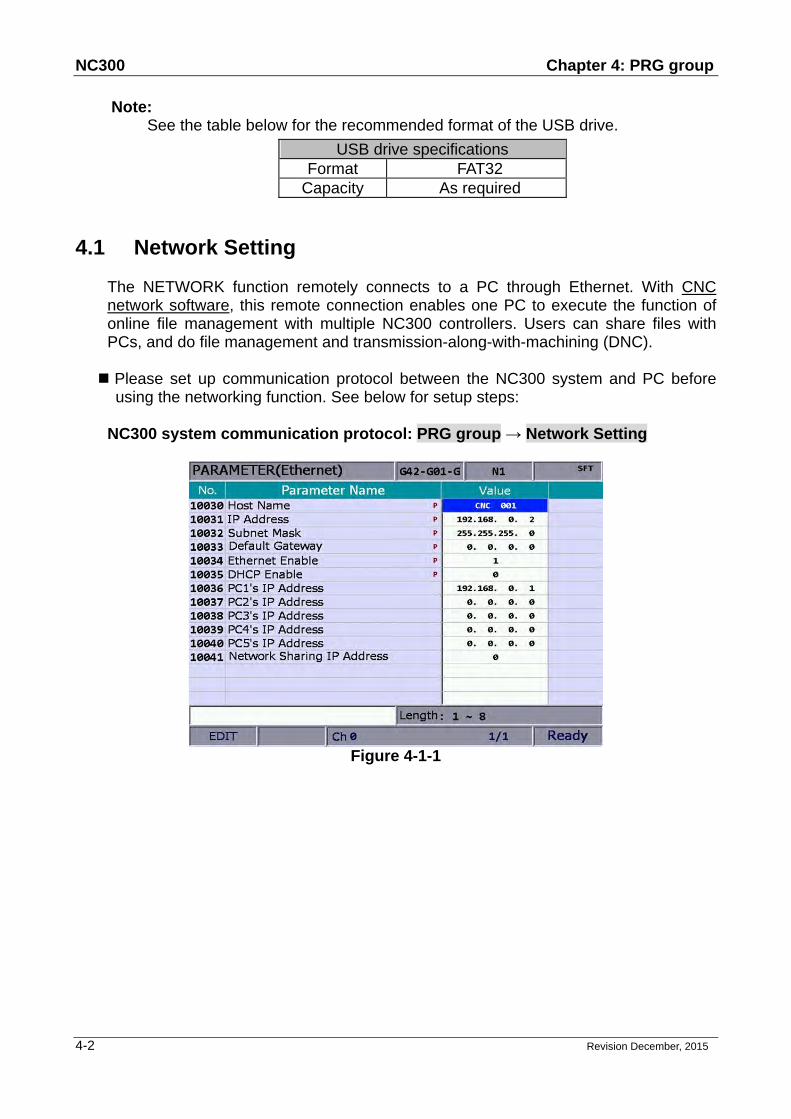
Note: See the table below for the recommended format of the USB drive.
USB drive specifications Format FAT32
Capacity As required
4.1 Network Setting
The NETWORK function remotely connects to a PC through Ethernet. With CNC network software, this remote connection enables one PC to execute the function of online file management with multiple NC300 controllers. Users can share files with PCs, and do file management and transmission-along-with-machining (DNC).
Please set up communication protocol between the NC300 system and PC before
using the networking function. See below for setup steps:
NC300 system communication protocol: PRG group → Network Setting
Figure 4-1-1

Chapter 4: PRG group NC300
Revision December, 2015 4-3
Network setup parameters Code Name Range or Formats
10030 Host name Length: 1 ~ 8 Actual setting: 1 ~ 8 characters
10031 IP address Length: ×××.×××.×××.××× Actual setting: 192.168.0.2
10032 Subnet mask Length: ×××.×××.×××.××× Actual setting: 255.255.255.0
10033 Default gateway Length: ×××.×××.×××.××× Actual setting: 0.0.0.0
10034 Network function ONLength: 0 ~ 1 Actual setting: 1
10035 DHCP ON Length: 0~1 Actual setting: 0
10036 IP address of remote computer 1
Length: ×××.×××.×××.××× Actual setting: 192.168.0.1
10037 IP address of remote computer 2
Length: ×××.×××.×××.××× Actual setting: 0.0.0.0
10038 IP address of remote computer 3
Length: ×××.×××.×××.××× Actual setting: 0.0.0.0
10039 IP address of remote computer 4
Length: ×××.×××.×××.××× Actual setting: 0.0.0.0
10040 IP address of remote computer 5
Length: ×××.×××.×××.××× Actual setting: 0.0.0.0
10041 IP address of remote folder sharing
Length: 0 ~ 5 Actual setting: 0

NC300 Chapter 4: PRG group
4-4 Revision December, 2015
Communication protocol of PC: Set up TCP/IP in Networking of the operating system (see Figure 4-1-2) or CNC Network software → Setup
Network setup in PC operating system:
Figure 4-1-2
Steps: (a) Check "Use the following IP address" option then enter in sequence:
"IP address": 192 . 168 . 0 . 1 "Subnet mask": 255 . 255 . 255 . 0
(b) Press OK to complete the setting.

Chapter 4: PRG group NC300
Revision December, 2015 4-5
Network setup for Network software:
Figure 4-1-3
Steps: (a) Start the CNC Network software. Enter the Setup screen and enter the
settings listed below in sequence: "IP address": 192 . 168 . 0 . 1 "Subnet mask": 255 . 255 . 255 . 0
(b) Press "Search CNC" to connect with the CNC based on the settings given here.

NC300 Chapter 4: PRG group
4-6 Revision December, 2015
■ DNC connection: Through Network software, users may open the shared files in file sharing list. Then, execute G code in transmission-along-with-machining (DNC) mode via Ethernet. No extra disk space is required for file storage as only the path of shared files is recorded. See the operation steps described below:
1. Complete the Ethernet communication setting for connection between PC and NC300 system.
2. Start the CNC Network software. 3. Click the Function bar - DNC operation tab.
Figure 4-1-4
4. Enter the "EDIT mode" of NC300 system then enter the top layer NETWORK\Option in
file explorer.
Figure 4-1-5

Chapter 4: PRG group NC300
Revision December, 2015 4-7
5. After the shared file is displayed, select and open the G code file that has been set to share from the shared file.
6. Set NC300 to "Auto mode" then execute Cycle start to start running the G code file with DNC connection. The execution method is the same as the general file.
7. During DNC execution, file information can be displayed in the window of DNC provided by CNC Network software. The information includes name of connected system, name of running DNC file, total number of lines, executing line number and file contents. (File contents scroll down along with the execution progress as shown in Figure 4-1-6).
Figure 4-1-6
DNC transmission display

NC300 Chapter 4: PRG group
4-8 Revision December, 2015
4.2 Add (create new file) Users may use the Add function in "Edit mode" to create a new G code file from the controller interface. See the operation steps described below:
(1) Set the system to "EDIT mode".
(2) Press the key to switch to the screen of [PROGRAM].
(3) In the screen of [File manage], press or keys to move the cursor to the destination of the disk for file creation (e.g. the 2nd or the 3rd layer in CF or USB directory).
(4) Press the function key to display the funciton on next page.
(5) Press the key (NEW file) and the dialog box for file name will pop up.
Figure 4-2-1
(6) Type alphanumeric letters (symbols are not included) in the box and press the
key to create a new file.
Chapter 4: PRG group NC300
Revision December, 2015 4-9
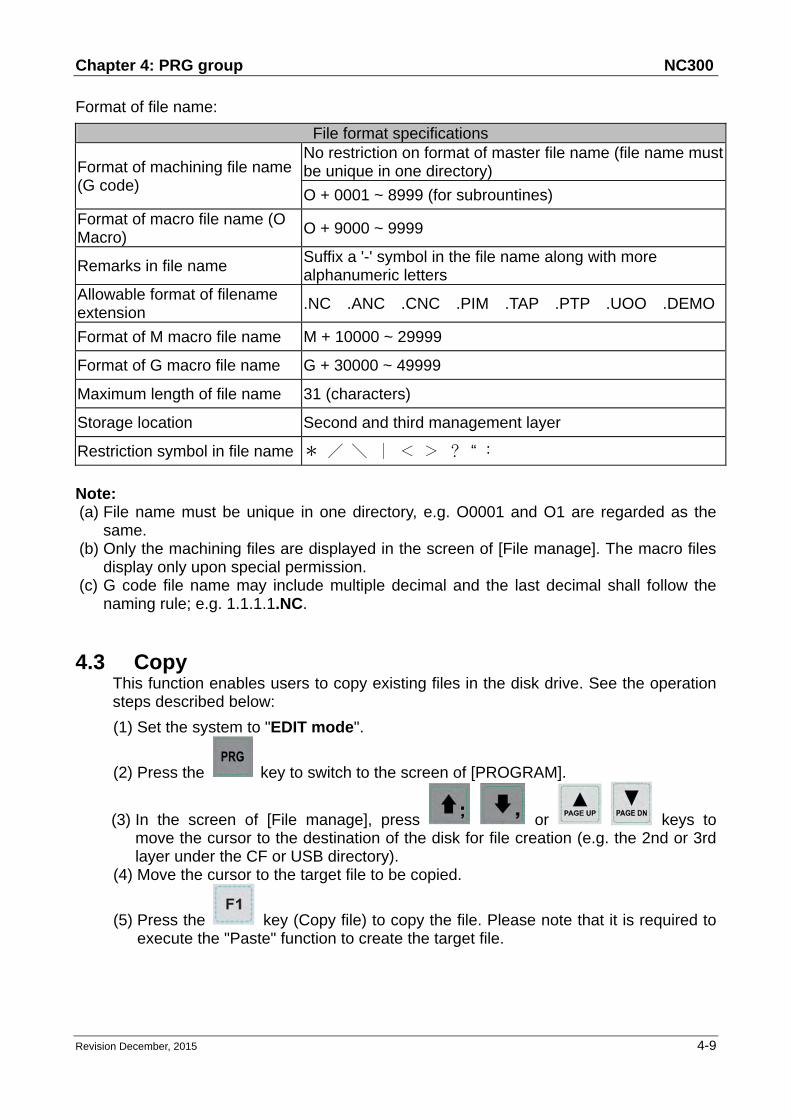
Format of file name:
File format specifications
Format of machining file name (G code)
No restriction on format of master file name (file name must be unique in one directory)
O + 0001 ~ 8999 (for subrountines)
Format of macro file name (O Macro)
O + 9000 ~ 9999
Remarks in file name Suffix a '-' symbol in the file name along with more alphanumeric letters
Allowable format of filename extension
.NC .ANC .CNC .PIM .TAP .PTP .UOO .DEMO
Format of M macro file name M + 10000 ~ 29999
Format of G macro file name G + 30000 ~ 49999
Maximum length of file name 31 (characters)
Storage location Second and third management layer
Restriction symbol in file name * / \ ∣ < > ? “ ﹕
Note: (a) File name must be unique in one directory, e.g. O0001 and O1 are regarded as the
same. (b) Only the machining files are displayed in the screen of [File manage]. The macro files
display only upon special permission. (c) G code file name may include multiple decimal and the last decimal shall follow the
naming rule; e.g. 1.1.1.1.NC.
4.3 Copy This function enables users to copy existing files in the disk drive. See the operation steps described below:
(1) Set the system to "EDIT mode".
(2) Press the key to switch to the screen of [PROGRAM].
(3) In the screen of [File manage], press or keys to move the cursor to the destination of the disk for file creation (e.g. the 2nd or 3rd layer under the CF or USB directory).
(4) Move the cursor to the target file to be copied.
(5) Press the key (Copy file) to copy the file. Please note that it is required to execute the "Paste" function to create the target file.

NC300 Chapter 4: PRG group
4-10 Revision December, 2015
4.4 Paste As described in Section 4-3, it is required to execute this function together with the Copy function to copy a file. This function is one of the management functions of PRG Group. See the operation steps described below (continued from Section 4-3).
(6) Press or keys to move the cursor to the disk, data directory or layer of the target file.
(7) Enter the directory of the target file, press the key (Paste). Then, enter a new name or use the old name of the target file in the popup dialog box. Press the
key and file coping and pasting is done.
Note: (a) Please note that if the newly copied file exists in the same directory, then its
name must differ from the source one. (b) The system prompts an information box with the message 'Please copy a file
at first' if no copy operation has been done beforehand. The file past function has no effect.
(c) Files in the USB disk can be copied and pasted to CF card with the steps described above.

Chapter 4: PRG group NC300
Revision December, 2015 4-11
4.5 Delete (for files and folders) This function deletes files and folders at the second layer of [File manage]. See the operation steps described below:
(1) Set the system to "EDIT mode".
(2) Press the key to switch to the screen of [PROGRAM].
(3) In the screen of [File manage], press or keys to
move the cursor and press the key to enter the disk location and data layer of the file or folder to be deleted.
(4) Point to the file or folder to be deleted.
(5) Press the key (DEL) and the "Do you really want to delete?" dialog box will
pop up. Press "Y" and the key to delete the selected file or folder.
Note: The deleted file cannot be recovered by undoing the delete operation.

NC300 Chapter 4: PRG group
4-12 Revision December, 2015
4.6 Select/Deselect multiple files In addition to single file operation, users may use the select/deselect function key from the function bar in [File manage] screen to select/deselect multiple files for copying or deleting. See the operation steps described below:
(1) Set the system to "EDIT mode".
(2) Press the key to switch to the screen of [PROGRAM]. (3) Enter the file directory for selecting multiple files.
(4) In the screen of [File manage], use keys or keys to
move the cursor to the desired files. Press the key (SEL TOGL) to select
or deselect the file (see Figure 4-6-1). Press the key (SEL ALL), all files
will be selected. For files that have been selected, pressing the key (CANCEL ALL) will cancel their selection.
Figure 4-6-1
(5) Press the key (Copy file) to copy multiple files.

Chapter 4: PRG group NC300
Revision December, 2015 4-13
(6) Move the cursor to another directory. Press the key (Paste) to paste multiple files as shown in Figure 4-6-2.
Figure 4-6-2
See the operation steps described below for deleting multiple files:
(1) Set the system to "EDIT mode".
(2) Press the key to switch to the screen of [PROGRAM]. (3) Enter the file directory for selecting multiple files.
(4) In the screen of [File manage], use keys or keys
to move the cursor to the desired files. Press the key (SEL TOGL) for
selection. For files that have been selected, pressing the key (SEL TOGL) again will cancel the selection.
(5) Press the key (DEL) and the dialog box for confirmation will pop up (see
Figure 4-6-3). Press "Y" and the key to delete the selected files.

NC300 Chapter 4: PRG group
4-14 Revision December, 2015
Figure 4-6-3
Note:
(a) After copying multiple files in one directory, users shall paste them to another folder, which the path has to be different. If trying to copy multiple files in the same folder, the system prompts users to select another destination path and ignore the pasting operation.
(b) When there are duplicated file names while copying multiple files, the NC300 numerical control system prompts users with an overwrite option dialog box. Users can select "Y" (yes) to overwrite the existing file, or select "N" (no) or press the "EXIT" key to ignore the pasting operation.

Chapter 4: PRG group NC300
Revision December, 2015 4-15
4.7 Rename Use this function to change the name of existing files. See the operation steps described below:
(1) Set the system to "EDIT mode".
(2) Press the key to switch to the screen of [PROGRAM].
(3) In the screen of [File manage], press or keys to move the cursor to the disk location and data layer for file creation (e.g. the 2nd or 3rd layer in the CF or USB directory).
(4) Press the key to switch to the function bar at next page.
(5) Move the cursor to the file that you wish to rename. Then, press the key (RENAME) and the dialog box for file name input will pop up.
(6) Enter a new name of the file which differs from any file in the directory and press
the key.
Note: (a) A G code file can be added in layer two or three but not layer one in [File
manage]. (b) The naming format for renaming and naming for new file follows the same
rule. If user enters a name that already exists in the directory, an error message will pop up and the renaming will be invalid.

NC300 Chapter 4: PRG group
4-16 Revision December, 2015
4.8 Create directory (Add folder) New directory for G code files can be created in the second manage layer in [File manage]. That is, the second layer of [File manage] may contain both directory folders and G code files. See the operation steps described below:
(1) Set the system to "EDIT mode".
(2) Press the key to switch to the screen of [PROGRAM].
(3) Press the key to switch to the function bar at next page.
(4) Press the key (FOLDER) in the second layer of the [File manage], the dialog box for entering directory name will pop up.
Figure 4-8-1
(5) Enter the name of the directory and press key to complete the creation.
This creates a new directory in the second layer of [File manage]. Users now can do file creation and editing of files (such as G code files) at the third layer of [File manage].
Format of directory name:
Format of directory name
Format of directory file name Any alphanumeric letter
Maximum length of directory name 31 (characters)
Storage location The 2nd management layer

Chapter 4: PRG group NC300
Revision December, 2015 4-17
4.9 File searching This function enables users search among many files and open a desired G code file. With a given file name users can search and open files quickly.
(1) Set the system to "EDIT mode".
(2) Press the key to switch to screen of [PROGRAM].
(3) In the screen of [File manage], press keys or keys
to move the cursor and press the key to go to the destination in the second or third layer in the disk.
(4) Press the key to switch to the function bar at next page.
(5) Press the key (FIND FILE) and the dialog box will pop up. Enter the
desired file name in the box and press the key to search and open the target file.
Note: (a) Instead of searching all directories, this file searching function is limited to
one directory. (b) To find the correct file and open it, please enter the complete and exact file
name you wish to search for.

NC300 Chapter 4: PRG group
4-18 Revision December, 2015
4.10 File merge This function copies and merges two G code files into one. See the operation steps described below:
(1) Set the system to "EDIT mode".
(2) Press the key to switch to screen of [PROGRAM].
(3) In the screen of [File manage], press keys or keys
to move the cursor and press the key to go to the destination in the second or third layer in the disk.
(4) Select the G code file that desire to copy.
(5) Press the key (COPY FILE) to save the file in the system's clipboard. (6) Move the cursor to the directory of the target file to be merged.
(7) Press the key to switch to the function bar at next page.
(8) Press the key (MERGE) and the dialog box will pop up. Enter the
desired file name and press the key to open the target file. (9) Move the cursor to the location in the target file to paste the source file. Press
the key (Paste) to merge both files. (10) Execute auto save, either by switching mode, opening other files or pressing
the RESET key, to complete the merge operation.

Chapter 4: PRG group NC300
Revision December, 2015 4-19
4.11 Sequencing Users can arrange the sequence of directory and files by applying this function.
This brings convenience when searching or managing files. (1) Set the system to "EDIT mode".
(2) Press the key to switch to screen of [PROGRAM].
(3) In the screen of [File manage], press keys or
keys to move the cursor and press the key to go to the destination in the second or third layer in the disk.
(4) Press the key to switch to the function bar at next page.
(5) Press the key (SEQUENCE) to display the function bar to the second row of the function page.
(6) Press the key (NAME) and then the directory and file will be displayed
by the sequence of number > English (from top to bottom). Press the key (NAME) again, the displayed sequence will be English > number (from top to bottom).
(7) Press the key (SIZE) and the file displayed sequence will start from
small > large (from top to bottom). Press the key (SIZE), the sequence will be large > small (from top to bottom).
(8) Press the key (DATE) and the then the directory and file will be displayed by the sequence of most recent > earlier (from top to bottom). Press
the key (DATE) again, the sequence will be earlier > most recent (from top to bottom).

NC300 Chapter 4: PRG group
4-20 Revision December, 2015
4.12 Convert DXF files This is the interface of file manager for DXF file. Users can select the DXF file first.
Then, enter the parameters values to convert the DXF file to the G code file. (1) Set the system to "EDIT mode".
(2) Press the key to switch to screen of [PROGRAM].
(3) Consecutively press the key to switch the function bar to the third row of the function page in this layer.
(4) Press the key (DXF) to display the interface of DXF file explorer.
(5) In the screen of [File manage], press keys or
keys to move the cursor and press the key to select the DXF file to be converted.
(6) Then, a dialogue box will pop up and ask users to enter the value. See the figure below.
Figure 4-12-1
(7) When you complete the setting of parameters values, press the key and an input box of “Enter new filename” will pop up.
(8) Then, press the key to convert DXF file and G code file is stored in CF directory.
(9) Now, users can execute the G code file that is just converted from DXF file.

Chapter 4: PRG group NC300
Revision December, 2015 4-21
4.13 Macro file This function manages and edits equipment-specific macro files. With the permission, users can use all the edit functions to manage and edit macro files as described in Section 4.14. Otherwise, users can only browse existing macro files but cannot view or edit the contents. Please contact the local service provider for permission for macro file editing.
4.14 File editing The edit group function enables users to edit and manage G code files. After a G code file is opened in the screen of [File manage], it will switch to the page for file editing. Move the cursor to any location in the file and then use the text, number, or edit keys in primary control panel to edit as required. After the editing is completed, switching mode, pressing the RESET key or open other files will automatically save the file. See the steps described below for file editing:
(1) Set the system to "EDIT mode".
(2) Press the key to switch to screen of [PROGRAM].
(3) Press keys or keys to move the cursor and press
the key to go to the destination in the second or third layer in the disk.
(4) Select the desired G code file and press the key to open the file and enter edit mode.
(5) Use keys to move the cursor to any location in the file.
(6) Press the text, number, and edit keys in primary control panel to edit as required.
(7) Save the changes by performing auto save operations, either by switching mode, opening other files, or pressing the RESET key.
Edit function specifications:
Edit function specifications The maximum number of characters per line 255 (characters)
Available editing modes Edit mode
Size limit of editable files Only the file with size less than 3MB can
be edited.
Note: (1) The edit relevant function bar displays only when entering the "edit mode" of the file
management or edit function. Otherwise, in non-edit mode, the PRG group function provides views and coordinates information display of currently open files only.
(2) Users can insert the string to “( )” in the end each block in G code file as the note. “( )” cannot be placed at the front of the command block. Or the block will be regarded as the note and be ignored.

NC300 Chapter 4: PRG group
4-22 Revision December, 2015
4.14.1 Search by line number This function enables users to search contents in running G code files by line number. See the steps described below for file editing:
(1) Set the system to "EDIT mode".
(2) Press the key to switch to screen of [PROGRAM].
(3) Press keys or keys to move the cursor and press
the key to go to the destination in the second or third layer in the disk.
(4) Select the desired G code file. Then, press the key to open the file and enter the screen for file editing.
(5) Press the key to switch to the function bar at next page.
(6) Press the key (LABEL) and the dialog box for entering line number (key pad 0 ~ 9) will pop up.
(7) Enter the desired line number and press the key. The cursor will move to the given line number and finish searching.
Line number search specifications
Line number search specifications
Maximum length of searching string 62 (characters)
Format of searching string Actual line number of program (key pad 0~9)

Chapter 4: PRG group NC300
Revision December, 2015 4-23
4.14.2 Search by strings This function enables users to search the program by strings. Searching results vary with the fuzziness of keywords. The searched string can also be replaced by the new one that you entered. See the steps described below for file editing:
(1) Set the system to "EDIT mode".
(2) Press the key to switch to screen of [PROGRAM].
(3) Press keys or keys to move the cursor and press
the key to go to the destination in the second or third layer in the disk.
(4) Select the desired G code file. Then, press the key to open the file and enter the screen for file editing.
(5) Press the key to switch to the function bar at next page.
(6) Press the key (STRING) and the dialog box for entering the string will pop up. See the figure below.
Figure 4-14-1
(7) Enter the desired string to be searched and replaced and press the key. The cursor will move to where the string occurred in the file.
(8) The string will be highlighted in block and the 'Forward', 'Backward', ‘Replace’ and ‘Replace all’ options are displayed in the function bar.
(9) Repeatedly press the key (NEXT) to search the next match. Press the

NC300 Chapter 4: PRG group
4-24 Revision December, 2015
key (PREV) to search the previous match.
(10) Press the key (REPLACE) and the system will replace one single string
by the one you entered. Or you can press the key (REPLACE ALL) to replace all strings that match to the searched one.
(11) Press the key to exit the string search page. The function bar resumes displaying options of file editing
(12) Please remember to save the editing result (It can save the file by switching modes, pressing ‘RESET’ or opening another file.)
String searching specifications
String searching specifications
Available editing modes Edit mode
Size limit of editable files Only the file with size less than 3MB can
be edited.

Chapter 4: PRG group NC300
Revision December, 2015 4-25
4.14.3 Block starting/ending point This function simplifies file editing in case a large section of program modification is required. Users can define a block by defining its starting and ending point with the cursor then edit the block with delete, copy and paste functions. See the steps described below:
(1) Set the system to "EDIT mode".
(2) Press the key to switch to screen of [PROGRAM].
(3) Press keys or keys to move the cursor and press
the key to go to the destination in the second or third layer in the disk.
(4) Select the desired G code file. Then, press the key to open the file and enter the screen for file editing.
(5) Press the key (B start) to set the current cursor position as the starting point of the block.
(6) Use keys to move the cursor to the position as desired block end.
(7) Press the key (B end) to set the current cursor position as the end of the block. See the figure below.
Figure 4-14-2
(8) Follows step (5) ~ (7) and press the key (DEL) to delete the text in the given block.

NC300 Chapter 4: PRG group
4-26 Revision December, 2015
(9) Follows step (5) ~ (7) and press the key (Copy) to copy text in this block.
Move the cursor to the desired area for pasting and press the key (Paste) to paste the selected text.
4.14.4 Delete (lines and blocks) This function deletes the entire line where the cursor is located or the block set up earlier. It also can delete the text of the entire block with the setting of block at starting and ending points. See the steps described below:
(1) Set the system to "EDIT mode".
(2) Press the key to switch to screen of [PROGRAM].
(3) Press keys or keys to move the cursor and press
the key to go to the destination in the second or third layer in the disk.
(4) Select the desired G code file. Then, press the key to open the file and enter the screen for file editing.
(5) Move the cursor to the line to be deleted and press key (DEL) to delete the entire line.
(6) Delete a program block in the same way as described in Section 4-14-3. See step (8) for defining the starting and ending points of a block.
4.14.5 Copy and paste (line and block)
Move the cursor to the desired line. Then, press the copy function key and paste the text to the selected location; both copy and paste keys have to be used to fulfill the function. It allows users to copy the text in a single line but also the entire block. See the operation steps described below:
(1) Set the system to "EDIT mode".
(2) Press the key to switch to screen of [PROGRAM].
(3) Press keys or keys to move the cursor and press the
key to go to the destination in the second or third layer in the disk.
(4) Select the desired G code file. Then, press the key to open the file and enter the screen for file editing.

Chapter 4: PRG group NC300
Revision December, 2015 4-27
(5) Move the cursor to the desired line for copying and press the key (Copy).
(6) Move the cursor to the target location and press the key (Paste) to paste the line.
(7) The entire block can be copied as described in Section 4-14-3. See step (9) for defining the starting and ending points of a block.
4.14.6 Undo
Users can press the 'undo' key to cancel previous editing operations for up to seven steps. See the steps described below:
(1) Set the system to "EDIT mode".
(2) Press the key to switch to screen of [PROGRAM].
(3) Press keys or keys to move the cursor and press
the key to go to the destination in the second or third layer in the disk.
(4) Select the desired G code file. Then, press the key to open the file and enter the screen for file editing.
(5) Press the key (Undo) to undo the last action.

NC300 Chapter 4: PRG group
4-28 Revision December, 2015
4.15 Other mode functions Auto mode (AUTO): After entering the PRG group screen, the contents of the currently opened G code file will be displayed. Users will be able to view the status information of the currently opened/executed file as well as the line being executed. The PRG group function in auto mode displays information relevant to program execution and coordinates of movements during program running. See the operation steps described below:
(1) Press key in "Auto mode" to display status of program running in full screen as illustrated in the figure below.
Figure 4-15-1
(2) Press the key again to switch to the screen which displays both program and coordinates. See the figure below.
Figure 4-15-2
Current group screen
Content of program being executed
Information of each coordinate being executed
Current system mode
Name of current program
Current command status
Line being executed
F.act: actual feed rate S.act: actual spindle speed D: tool radius
compensation ID H: tool length
compensation ID T: tool ID F: Feed rate S: Spindle speed t: pause time CYC: Single machining time
Current motion factor

Chapter 4: PRG group NC300
Revision December, 2015 4-29
When program is stopped, the breakpoint search function (Search) in auto mode automatically records the line number where it is stopped (see DGN_system information for relevant information screen). ; it will quickly do the computing and execute the program content prior to the breakpoint . See the figure below for illustration.
Figure 4-15-3
See the operation steps below:
(1) Press the key in "Auto mode" to enter the screen of [PROGRAM].
(2) Press the key (START) and the screen of breakpoint search will pop up. (3) Refer to the breakpoint line number shown in the screen, enter the desired
program line or sequence number. Then, press the key to complete the setting.
(4) Press the key (RUN) to quickly execute the program and go to the re-starting line or sequence number.
(5) Before executing to the specified line, the controller will automatically execute the program and record its status. The system stops at the breakpoint line and waits for its execution.
(6) Press the “Cycle start" key to resume normal program execution. Note:
(1) The system stops program execution when reaching the block after the
breakpoint. This block remains unexecuted until the Cycle start key is pressed
and the system resumes normal operation.
(2) Valid search formats are the line and N number of the program.
(3) During program running or breakpoint search function is performing, any
request for breakpoint search will be ignored as the system regards it as in
program running status.

NC300 Chapter 4: PRG group
4-30 Revision December, 2015
The SF setup function can be used to change the feeding speed (F command) and spindle speed (S command) during G code execution, see as Figure 4-15-4 below. By using SF setup function and entering the new command value, the speed command is changed when program running.
Figure 4-15-4
See the operation steps below:
(1) In Auto Mode, press the key to enter the screen of [PROGRAM].
(2) Press the key (SF set) and the dialog box for entering SF command will pop up.
(3) Enter new S or F values, then press the key and the speed is changed.
Note: (1) The SF settings are valid during single execution only while the S and F
values in the G code remain intact. For a G code that requires repeated
execution, it is recommended to edit the program and ensure the accuracy of
speed commands in Edit mode.
(2) After the S value is set, the spindle speed will be immediately changed in the
G code. On the other hand, when the F value is set, the new feed speed (F
command) takes effect only after new data in the system buffer is processed.
(3) Do not use this function to change the existing speed command for a G code
program without applying S and F commands.
(4) In SF setting, F command is enabled by the function of “Enable feed rate
speed setting “ in parameter No.10017.

Chapter 4: PRG group NC300
Revision December, 2015 4-31
By using the bar-code reader, the File Scan function can quickly load in and
sequence the machining files that are named by bar code. This saves the time for file
searching. The bar-code reader can be installed via the USB port.
Figure 4-15-5
See the operation steps below:
(1) In Auto Mode, press the key to enter the screen of [PROGRAM].
(2) Press the key (SCAN) to switch the screen for displaying. See figure 4-15-5.
(3) Use the bar-code reader to acquire the machining filename.
(4) Press the key (LOAD) to load in the file content.
(5) Or press the key (CLR) to delete one file that displayed on the top of the scanning list.
(6) Or you can press the key (CLR ALL) to delete all files displayed from the list.
Note:
(1) The machining file that will be loaded in the system by scanning its bar
code should be created in CF card in advance. Also, its filename has to be
identical to the bar code.

NC300 Chapter 4: PRG group
4-32 Revision December, 2015
JOG and hand wheel feeding mode (JOG, MPG): See the SF setting steps described below:
(3) In JOG mode or MPG mode, press the key to enter the screen for program execution.
(4) Press the key (SF set) and the dialog box for SF command input will pop up.
(5) Enter new S or F values. Then, press the key and the speed is changed.
Teach Programming : When users manually move the axis to any position, using
function keys of teach programming can automatically convert the coordinates value of
three axes into a motion command of one single block. This function shall be performed
in JOG or Hand wheel mode. The function of teach programming is in PRG group,
which can be operated in existing files or new files. Functions include rapid moving,
linear cutting, arc cutting, deleting, creating files, saving files and selecting absolute /
mechanical coordinates. It will automatically convert the file into the corresponded
command format according to different functional selections. See below for the
converting format.
Function The converted command format Create a new file when teach programming is enabled.
G90 G40 G49 G98 G50 G64 G80 G17 G69 G21 G54 G15 S3000 M03 F1000 ※According to the parameter (unit of length), it converts to G21 or G20 command.
Rapid G00 + X_Y_Z_ Linear Cutting G01 + X_Y_Z_ Arc Cutting G02 or G03 + X_Y_Z_ + I_ J_
※According to plane X-Y, Z-X and Y-Z, it converts to G17+I_ J_, G18+K_ I_ and G19+J_K_ respectively.
Absolute Coordinate
G90 G00 (or G01/G02/G03) + X_Y_Z_
Mechanical Coordinate
G53 G00 (or G01/G02/G03) + X_Y_Z_
See the operation steps below for Teach programming:
(1) In “JOG mode” or “hand wheel mode”, press the key to enter the screen for performing the function.
(2) Press the key (TEACH) to enter the screen for teach programming. (3) Select the file and do teach programming in current file or new one. If desire to

Chapter 4: PRG group NC300
Revision December, 2015 4-33
do programming in current file, users have to open the file in Edit Mode. If
programming in a new file, press the key (NEW FILE) to enter the file
name in a pop-up input box. Then, press the key and users can create new files in current directory path.
(4) Specify the data type of coordinates point. For example, to select the absolute
coordinate, press the second toolbar and then press the key (ABS). Or
press the key (MECH) once to switch the data type as mechanical coordinates.
(5) Move the axis to the specified position in “JOG mode” or “Hand wheel mode”.
Then, press the key (RAPID) or the key (LINEAR) according to the requirement of motion mode, which means to insert the coordinates command at cursor position. And the coordinates command is generated based on the data type of its value.
(6) To continue Step (5), when it specifies arc motion, press the key (ARC) to display the toolbar of acr cutting.
(7) Then, specify arc plane setting. Press the key (PLANE SEL) to select plane of X-Y, Y-Z or Z-X.
(8) Move and setup the start point, middle point and end point of the arc in
sequence by pressing , and key (P1, P2 and P3). When the setting of P3 is complete, it is automatically converted into arc cutting command. The system will determine whether it is G02 or G03 and calculate its radius value then figure out the arc direction based on the sequence between P1 and P3.
(9) If the coordinates command is incorrect, move the cursor to the block. Press
the key (DEL) in the first layer of toolbar in teach programming to delete the block.
(10) When complete the operation of teach programming, apart from the auto-saving function (RESET, system switch mode, file switch), users can
save the programming result when pressing the key (SAVE). Note:
(1) Teach programming has to be done in Jog mode or Hand wheel mode;
otherwise, the function will not be displayed.
(2) The file size for teach programming is the same as file editing (under 3
MB).

NC300 Chapter 4: PRG group
4-34 Revision December, 2015
(3) For files created by teach programming, its filename has to comply with
the naming rules.
(4) When continuously input two same points, the second point will be ignored so
as to avoid the ineffectiveness of motion block.
(5) P1, P2 and P3 of arc command needs to be set up in sequence. Their
positions determine the arc direction command and the distance of the circle
center.
(6) When the function of teach programming is enabled and no file is opened, the
system will generate a blank file named “TEACH.NC” in the directory at the
cursor position (Default: The file is generated in root directory of CF). Then,
users may directly use the function of teach programming.
(7) In SF setting, F command is enabled by the function of “Enable feed rate
speed setting “ in parameter No.10017.
Manual input mode (MDI): The PRG group provides simple program entry, save, clear, and execution functions in manual mode. See the figure below for the program editing screen. This is exclusive to manual mode. Before the manually edited program is loaded in the system, cursor displays in a regular form which means the program is not running. Users can enter up to 17 lines of program steps. It is required to load the program again before running it. Otherwise, it cannot be executed.
Figure 4-15-6

Chapter 4: PRG group NC300
Revision December, 2015 4-35
Figure 4-15-7
The file save function saves the manual edit file in the current directory following the same naming rule that described in Section 4-2 Create new file. It requires giving a unique name in the current directory and with a format compliant with this standard. The clear function removes all contents in the programming page of manual mode. It functions the same as pressing and holds the RESET key for 3 seconds.
Note:
(1) The RESET key has two functions in manual mode. The first one is the same as in auto mode which aborts the execution of a program and returns to the first line of a manual entry program. The second can clear the contents in the manual entry area by pressing and holding the RESET key for 3 seconds.
(2) If the block of M30 is included, after the execution is complete, the cursor will return to the first line and execute line display.
(3) If the block of M30 is not included, after the execution is complete, the cursor stops at the last line and executes cursor display.
(4) If the last block of the program is M02, after the execution is complete, the cursor stops at the last line and executes line display.

NC300 Chapter 4: PRG group
4-36 Revision December, 2015
(This page is intentionally left blank.)

Chapter 5: OFS group NC300
Revision December, 2015 5-1
Chapter 5: OFS group
The OFS group provides setup functions for workpiece setup, cutting tool length or radius compensation, and variables of macros.
5.1 Coordinates setting The coordinate system (G54 ~ G59) provides a function for setting multiple workpiece coordinate system. Together with the workpiece coordinates system (G54 ~ G59) command, the G code command simplifies coordinate calculation during program coding and enhances flexibility in changing coordinate data for machining. This data table enables users to designate coordinate data by working together with any workpiece coordinates system command in G54~G59 of G code as illustrated in the figure below.
Figure 5-1-1
See the operation steps below:
(1) Press the key to enter the screen of [Offset menu].
(2) Press the key (Coord) to enter the screen of coordinates system setup function bar.
Note:
(a) Setting up coordinate system is allowed only when no machining program is executing. Otherwise, data entry will be rejected by the system.
(b) End of execution of a single block is regarded as in non-running status while a paused program is in running status.
Coordinates system setup Offset coordinates / G54~G59
Coordinates information Mechanical coordinates / relative coordinates

NC300 Chapter 5: OFS group
5-2 Revision December, 2015
5.1.1 Auto setting The auto setting function inputs the current position of each axis to the coordinates system (G54 ~ G59) where the cursor is. The input method includes single axis, multiple axis and L/2. The L/2 input shall work together with the clear function of relevant axis. The auto setting function also clears the numeric values of a given coordinates system with sub-functions of relative clear, all clear, L input, L/2 input and P input. The All Clear function clears all axes values of the current coordinates system to zero while all other coordinate systems' values remain unchanged. See the operation steps below:
(1) Press the key to enter the screen of [Offset].
(2) Press the key (Coord) to enter the screen of coordinates system setup function bar.
(3) Press the key (Auto) to switch to the screen with the coordinates auto setup function bar.
(4) Use keys to move the cursor to the position of the specified coordinate system group.
(5) Press the key (CLR ALL) to remove all coordinates group data where the cursor resides.
Relative clear: This function clears the relative coordinates that correspond to the
cursor position. Axis types are determined by cursor position, while those irrelevant to the cursor remain unchanged. This function clears relative coordinate value in the coordinates display rather than the data of the actual workpiece coordinate system.
L/2 input: When identifying the center of an object and to regard this center as the origin of the coordinate system, this function is able to automatically figure out the coordinate data and complete the setting.
See the operation steps below: (illustration based on X-axis)
(1) In [Jog mode] or [Hand wheel mode], move the mechanism to the X-axis of the workpiece coordinate and regard the first contact point as the origin on the X-axis.
(2) Press the key to enter the screen of [Offset].
(3) Press the key (Coord) to enter the screen of coordinates system setup function bar.
(4) Press the Auto key to switch to the screen with the coordinates auto setup

Chapter 5: OFS group NC300
Revision December, 2015 5-3
function bar.
(5) Use keys to move the cursor to the X-axis coordinates position of the specified coordinate system group.
(6) Press the key (SET L/2) to enter the L/2 input screen.
(7) Press the key (Point1). See Figure 5-1-2, the first circle on the rectangle turns red; this means the recording of the first mechanical coordinate value is complete.
Figure 5-1-2
(8) Move the mechanism to the contact point on the other side of the X-axis.
(9) Press the key (Point2). See Figure 6-1-2.When the second circle turns red, it means the mechanical coordinate value of the second point has been recorded.
(10) Press the key (SET). The system will figure out the origin on the X-axis of the workpiece coordinates. It will measure the distance from the mechanical origin to the end of the X-axis of the workpiece coordinates. This value times 0.5 will be the center on the X-axis of this coordinates.

NC300 Chapter 5: OFS group
5-4 Revision December, 2015
L input: This function automatically inputs the current mechanical coordinates by individual axis. When the cursor is moved to the X, Y, or Z field of the specified coordinates system, the L input function inputs the current mechanical coordinate value to the field that corresponds to the cursor position. This function inputs single-axis coordinate data only. See the operation steps below:
(1) In [Jog mode] or [Hand wheel mode], move the mechanism to the first contact point on the X-axis of the workpiece coordinates.
(2) Press the key to enter the screen of [Offset menu].
(3) Press the key (Coord) to enter the screen of coordinates system setup function bar.
(4) Press the key (Auto) to switch to the screen with the coordinates auto setup function bar.
(5) Use keys to move the cursor to the designated coordinate group and coordinate value of the axis. e.g. the setup position of X-, Y-, or Z-axis.
(6) Press the key (SET L) and the axis coordinate value input from the highlighted part is complete.
Example of L input (for the X-axis):
Move the mechanism to the specified position in the coordinate system, as with the origin on the X-axis of the workpiece coordinates in Figure 5-1-4.
Figure 5-1-4
Mechanical origin
Workpiece length
Workpiece X-axis workpiece Origin
X-axis

Chapter 5: OFS group NC300
Revision December, 2015 5-5
The mechanical coordinate data is shown in mechanical coordinate fields of Figure 5-1-5. Move the cursor to the specified coordinate group, such as G56 group in Figure 5-1-5. Then, press F3 key (SET L) and the X-axis data of the mechanical coordinate is inputted to the X-axis fields of the G54 automatically. The single axis data input of the coordinate group is now completed.
Figure 5-1-5
P input: This function inputs the coordinate center of multiple axes concurrently after
the workpiece center point is calibrated. With P input function, more than one axis, including X-, Y- and Z-axis can be inputted. See the operation steps below:
(1) In [Jog mode] or [Hand wheel mode], move the mechanism to the initial contact point on the X-axis of the workpiece coordinates.
(2) Press the key to enter the screen of [Offset menu].
(3) Press the key (Coord) to enter the screen of coordinates system setup function bar.
(4) Press the key (Auto) to switch to the screen with the coordinates auto setup function bar.
(5) Use keys to move the cursor to the data position for the coordinates system group.
(6) Press the key (SET P), multiple axis data is now automatically inputted into the highlighted coordinate group fields.
Note: Do not press All Clear function key to clear the coordinate value, or it would
clear the coordinate values of all other axes that have been set.

NC300 Chapter 5: OFS group
5-6 Revision December, 2015
Example of P input: Move the mechanism to the specified coordinate position, e.g. the workpiece origin in Figure 5-1-6. (Figure 5-1-6 indicates the relative position of the X- and Y-axis but not the Z-axis.)
Figure 5-1-6
After the workpiece origin is calibrated, the mechanical coordinate data is shown in the mechanical coordinate fields in Figure 5-1-7. Move the cursor to the specified coordinates group (e.g. the G54 group in Figure 5-1-7). Press F5 key (SET P), and then the X-, Y-, and Z-axis data of the mechanical coordinate are inputted to the mechanical coordinate fields of the G54 coordinates group. That is, the multiple axis data input for the axis group is completed.
Figure 5-1-7
Y-axis
Mechanical origin
X-axis
Workpiece origin
Workpiece

Chapter 5: OFS group NC300
Revision December, 2015 5-7
5.1.2 Absolute input The value of coordinate system can be inputted manually by absolute or incremental value setups. This section explains the steps for absolute input. See the operation steps below:
(1) Press the key to enter the screen of [Offset menu].
(2) Press the key (Coord) to enter the screen with coordinates system setup function bar.
(3) Use keys to move the cursor to the X-, Y-, and Z-axis setup positions of the specified coordinates system.
(4) Input positive or negative values by pressing keys - . To enter a
negative value, press the key in advance. Press the key to confirm the unit of values.
(5) Press the key (ABS) to enter the value of the coordinate.
Note: (a) The unit of value is mm. Value without decimal points is in unit of μm. That is,
input value 123456 indicates 123.456 mm. (b) The absolute input can be made by step (5) as described above or by
pressing the ENTER key.

NC300 Chapter 5: OFS group
5-8 Revision December, 2015
Example of absolute input: Move the tool center from mechanical origin to the origin of the workpeice coordinates.
Next, input this coordinate value (X and Y) to the controller’s OFS group (G54 ~ G59). Then, execute the corresponded command in the G code program and the setting for origin of the workpiece coordinates is complete.
Figure 5-1-8
Figure 5-1-9
Workpiece

Chapter 5: OFS group NC300
Revision December, 2015 5-9
5.1.3 Incremental input This is one of the manual methods for inputting coordinate data. Generally, incremental input is applied for fine tuning as the value is input incrementally. For example, if the original value is150.000, with an incremental input of 5.000, the new value shall be 155.000. See the operation steps below:
(1) Press the key to enter the screen of [Offset].
(2) Press the key (Coord) to enter the screen with coordinates system setup function bar.
(3) Use keys to move the cursor to the X-, Y- and Z- axis setup position of the specified coordinates system.
(4) Input positive or negative values by pressing keys - . To enter a
negative value, press the key in advance. Then, press the key to confirm the unit of value.
(5) Press the key (INC) to incrementally increase or decrease the axis.
Note: (a) When manually inputting the data, please make sure the value and the
inputting method is correct so as to avoid the danger caused by any incorrect movement.

NC300 Chapter 5: OFS group
5-10 Revision December, 2015
5.1.4 Rectangle center This function assists users in setting up coordinate data of the rectangle center with a rectangle drawing as shown in the figure below. The system converts data of the four corners into coordinate value of the object's actual center as illustrated in the figure below.
Figure 5-1-10
See the operation steps below:
(1) Press the key to enter the screen of [Offset].
(2) Press the key (Coord) to enter the screen with coordinate system setup function bar.
(3) Use keys to move the cursor to data fields for coordinates system designation.
(4) Press the key (SQUARE) to enter the screen of rectangle center. (5) As guided by the rectangle shown in the screen, move the spindle center to the
mechanical position of X1, X2, Y1 and Y2, press (X1, X2, Y1, Y2) keys to set up the coordinates data of each point.
(6) Press the key (Set) after coordinates of the four points are set, the system will figure out the coordinate data of the rectangle center and input the data to the coordinates system.
(7) Set up the coordinate position by moving the Z-axis, press the key (SET Z) to set up the Z-axis coordinates of the workpiece coordinates group.

Chapter 5: OFS group NC300
Revision December, 2015 5-11
Example of rectangle center: Firstly specify the fields of coordinates group. Then, manually move the spindle to the four corners of the object, enter the X and Y coordinates data of these 4 points as shown in Figure 5-1-11.
Figure 5-1-11
After the coordinates of the four rectangle corner points are set, press the F5 key (Set); the system will then figure out the actual mechanical coordinates value of the rectangle object center and set up given coordinates system data as shown in Figure 5-1-12.
Figure 5-1-12

NC300 Chapter 5: OFS group
5-12 Revision December, 2015
5.1.5 Circle center This function sets up the coordinates data of the center of any ball object. Select any 3 points on the ball object and set up their coordinates data; the function can figure out the coordinates of the object center as shown in the figure below:
Figure 5-1-13
See the operation steps below:
(1) Press the key to enter the screen of [Offset].
(2) Press the key (Coord) to enter the screen with coordinates system setup function bar.
(3) Use keys to move the cursor to data fields of the specified coordinates system.
(4) Press the key (CIRCLE) to enter the screen of circle center.
(5) Move the mechanical position of P1, P2 and P3 as guided. Then, press the
(P1, P2, P3) keys to set up the position one by one.
(6) After setting up coordinates of the three points on a circle, press the key (Set); the system will automatically figure out the coordinates data of the circle center and input the data to the coordinates system.
(7) Set up coordinate position by moving the Z-axis, press the key (SET Z) to set up the Z-axis coordinates of the workpiece coordinates group.

Chapter 5: OFS group NC300
Revision December, 2015 5-13
Example of circle center This function applies to any workpiece in a ball object. Manually move the spindle to
access any three outer points on the circle, and then set up the coordinate value of these three points by relevant function keys as shown in Figure 5-1-14.
Figure 5-1-14
After the coordinates of any three outer points are set, press the F4 key (Set), the system will then automatically figure out the actual mechanical coordinates value of the circle center and sets up given coordinates system data as shown in Figure 5-1-15.
Figure 5-1-15

NC300 Chapter 5: OFS group
5-14 Revision December, 2015
5.2 Tool register This function varies with tool length compensation (G43 or G44, or cancel command G49) or radius compensation (G41 or G42, or cancel command G40). The tool register function covers tool length compensation, radius compensation, length wear compensation, and radius wear compensation and tool life span management functions. The data fields correspond to H (tool length compensation) and D (tool diameter compensation) codes assigned by the machining program. The tool register settings can assign tool length or tool radius fields data to meet a given machining path and size without program modifications. The numeric data setup covers absolute input, incremental input, H setup, and data clearance functions. See the figure below for the tool compensation function screen.
Figure 5-2-1
Range of tool register values Range of tool length data -2000.0 ~ 2000.0 mm Range of tool radius data -150.0 ~ 150.0 mm
Range of tool length wear compensation data -2000.0 ~ 2000.0 mm
Range of tool radius wear compensation data -150.0 ~ 150.0 mm
Range of tool life span 0 ~ 99999999 serves
Compensation Data: Tool length; Tool radius; Length compensation; Radius compensation
Auxiliary Display: Mechanical coordinates and actual position of current Z-axis
Compensation Code (H/D)
Compensation data input field
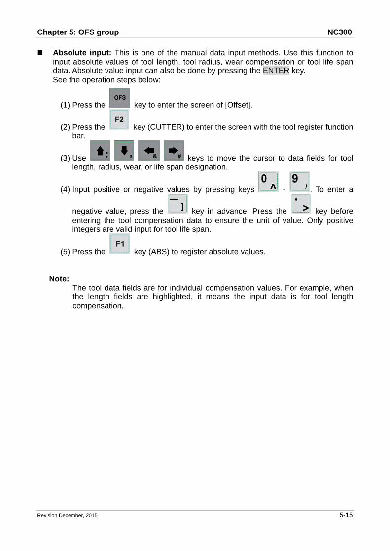
Chapter 5: OFS group NC300
Revision December, 2015 5-15
Absolute input: This is one of the manual data input methods. Use this function to input absolute values of tool length, tool radius, wear compensation or tool life span data. Absolute value input can also be done by pressing the ENTER key. See the operation steps below:
(1) Press the key to enter the screen of [Offset].
(2) Press the key (CUTTER) to enter the screen with the tool register function bar.
(3) Use keys to move the cursor to data fields for tool length, radius, wear, or life span designation.
(4) Input positive or negative values by pressing keys - . To enter a
negative value, press the key in advance. Press the key before entering the tool compensation data to ensure the unit of value. Only positive integers are valid input for tool life span.
(5) Press the key (ABS) to register absolute values.
Note: The tool data fields are for individual compensation values. For example, when the length fields are highlighted, it means the input data is for tool length compensation.

NC300 Chapter 5: OFS group
5-16 Revision December, 2015
Incremental input: This is one of the manual data input methods. Use this function to input incremental values of tool length, tool radius, wear compensation or tool life span data. See the operation steps below:
(1) Press the key to enter the screen of [Offset menu].
(2) Press the key (CUTTER) to enter the screen with the tool register function bar.
(3) Use keys to move the cursor to data fields for tool length, radius, wear, or life span designation.
(4) Input positive or negative values by pressing keys - . To enter a
negative value, press the key in advance. Press the key before entering the tool compensation data to ensure the unit of value. Only positive integers are valid input for tool life span.
(5) Press the key (INC) to register incremental values.

Chapter 5: OFS group NC300
Revision December, 2015 5-17
H setup: This function automatically inputs the height of Z-axis of current mechanical coordinates in assigned tool length compensation data (H) exclusively. It can prevent input error during manual setup by users as well as reduce the time required for value setup. See the operation steps below:
(1) In [Jog mode] or [Hand wheel mode], move the Z-axis to specified coordinates height.
(2) Press the key to enter the screen of [Offset].
(3) Press the key (CUTTER) to enter the screen with the tool register function bar.
(4) Use keys to move the cursor to the tool length fields for tool code designation.
(5) Press the key (SET H) to set the current Z-axis mechanical coordinates value in the given fields.
Note: (a) The H setup function applies to tool length data fields only. (b) Do not change values in OFS group during program execution. Enter values
only when the program stops. The program stop status means the program is not in operation, a block is completed when single-block stop function is enabled, or after the RESET key is pressed.
(c) The length wear value is reset to zero when inputting tool length value with H setup.

NC300 Chapter 5: OFS group
5-18 Revision December, 2015
Clear: This function clears tool compensation values with options of geometry, wear, life span, and all clear.
Geometry clear: clear all tool length and radius values. Wear clear: clear all tool length compensation and radius compensation values. Life span clear: clear all tool life span values. All clear: clear all tool registry data.
See the operation steps below:
(1) Press the key to enter the screen of [Offset].
(2) Press the key (CUTTER) to enter the screen with tool register function bar.
(3) Press the key (Clear) to display clear function bar.
(4) Press the key (H/D) to clear tool length and radius values. Press the
key (Wear) to clear all tool length compensation and radius
compensation values. Press the key (Life) to clear all tool life span
values. Press the key (All) to clear all tool registry data.

Chapter 5: OFS group NC300
Revision December, 2015 5-19
5.3 Tool magazine register This function manages the tool positions corresponding to the tool magazine after tool exchanges. The tool magazine data is a table recording the actual tool pot positions and tool ID of the machine. It not only records and displays the tool pot position of individual tools but also changes the tool sequence in tool magazine data fields with permission. The tool magazine register function runs in Jog feeding mode only. See the figure below.
Figure 5-3-1
See the operation steps described below for tool magazine setup:
(1) Set the system to "Jog feeding mode".
(2) Press the key to enter the screen of [Offset].
(3) Press the key (MAGA) to enter the tool magazine data setup function screen.
(4) Use keys to move the cursor to the assigned data fields.
(5) Enter the newly changed tool ID, press the key (Set) (or press the key) to set up the position of new tool magazine.
Current group screen
Name of current program
Line being executed
Spindle tool ID
Each current motion rate
Tool ID input field
The sequential status of tool ID
Tool magazine system number Current command tool ID Current standby ID Current standby tool pot ID

NC300 Chapter 5: OFS group
5-20 Revision December, 2015
Example of tool ID exchange: If the assigned tool ID duplicates one in existence, then it exchanges it with the one at the original place automatically. This ensures that each tool ID in the tool magazine does not duplicate another and prevents incorrect tool calling.

Chapter 5: OFS group NC300
Revision December, 2015 5-21
Operation description: Figure 5-3-2: initial status of the tool magazine with tools in it in numeric sequence Figure 5-3-3: set position 1 = 2, and tools ID 1 and 2 in tool magazine 1 and 2 exchanges with each other. Figure 5-3-4: set position 3 = 5, and tools ID 3 and 5 in tool magazine 3 and 5 exchanges with each other.
This demonstrates that tool IDs in the tool magazine exchange with each other after the tool ID of a given tool magazine number is changed. This eliminates errors caused by invalid tool ID accessing. All reset: The tool register also provides the reset function of tool magazine position.
This resets the tool ID in the tool magazine to default, i.e. both tool magazine and tool ID are in numeric sequence. This function can be used for misplacement troubleshooting or tool ID reset. See the operation steps below:
(1) Set the system to "Jog feeding mode".
(2) Press the key to enter the screen of [Offset].
(3) Press the key (MAGA) to enter the screen of tool magazine data setup function.
(4) Press the key (RST ALL) to reset all tool magazine position records. Tool magazine block: This function blocks the tool magazine position not used by the
program. Tools in a blocked tool magazine position cannot be called. If they are called incorrectly, the system blocks their use, warns with an error message, and will halt program execution immediately. This provides the protection mechanism against errors caused by incorrect tool calling. For example, users can block a tool magazine position with damaged positioning latch or that might interfere with adjacent large diameter tools. A blocked tool magazine position is identified by a different color. See the operation steps below:
(1) Set the system to Jog feeding mode.
(2) Press the key to enter the screen of [Offset].
(3) Press the key (MAGA) to enter the screen of tool magazine data setup function.
(4) Use keys to move the cursor to assigned data fields.
(5) Press the key (LOCK) to block the tool magazine position as shown in Figure 5-3-5.

NC300 Chapter 5: OFS group
5-22 Revision December, 2015
Figure 5-3-5

Chapter 5: OFS group NC300
Revision December, 2015 5-23
Example of tool magazine block: Use this function to block a tool magazine adjacent to one that has a large diameter tool. Blocking these two tool magazines can stop the operation of an improper tool ID calling program and protects tools from colliding with large-diameter tools in neighboring tool magazine.
Figure 5-3-6
Figure 5-3-7
When T1 holds a large diameter tool, it may interfere with adjacent tools as shown in the figure to the left. Once blocked by this function, the T2 and T16 tool magazine positions cannot be called any more.

NC300 Chapter 5: OFS group
5-24 Revision December, 2015
■ Tool magazine unlock: This function can unlock the block tool magazine. See the operation steps below:
(1) Set the system to Jog feeding mode.
(2) Press the key to enter the screen of [Offset].
(3) Press the key (MAGA) to enter the screen of tool magazine data setup function.
(4) Use keys to move the cursor to the assigned data fields.
(5) Press the key (UNLOCK) to unlock the tool magazine position. (6) Users also can directly enter the tool ID in the data field of locked tool magazine
and then press the key to unlock the tool magazine position.

Chapter 5: OFS group NC300
Revision December, 2015 5-25
※ Multi tool magazines management function For applications that require multiple tool magazine management systems, with the
permission, users may open the multi tool magazine management function through the tool magazine parameter. Users may assign a different number of tool pots for each tool magazine as well as the corresponding tool ID. The [Tool Magazine 1 and 2] function bars are used for managing tool ID in either tool magazine system. Please contact an equipment dealer/service provider for multi tool magazine relevant functions.
Figure 5-3-8
Note: (a) The tool magazine ID can be set up in "Jog feeding mode" (JOG) only. The
tool magazine setup option will not be shown in other modes. (b) The special user permission is a must before doing tool magazine ID setup or
reset. (c) No tool IDs are identical in one tool magazine. When assigning one existing
tool ID, the system will re-number this tool ID. In this case, the tool ID recorded at each address in tool magazine will be different to avoid incorrect tool calling.
(d) When the spindle's initial tool ID is set to T0, once T0 is placed in one tool magazine, that tool magazine is recorded as the position of T0 and cannot be blocked. When the field of tool magazine is T0, it is not allowed to block and the message "Tool ID Tool magazine cannot be blocked" will pop up.

NC300 Chapter 5: OFS group
5-26 Revision December, 2015
5.4 Macro variable Use variable input setup of this function along with variable command for various MLC data I/O, condition computing, and controls. The macro variable function covers local, global, retaining variables and expanded variables with values in double format.
Figure 5-4
5.4.1 Local variable
Local variables are used by the macro program in the local area and are numbered from 1 ~ 50. See the operation steps below:
(1) Press the key to enter the screen of [Offset].
(2) Press the key (Macro) to enter the screen of variable entry.
(3) Press the key (Local) to enter the entry screen for field ID starting with number 1.
(4) Use keys to move the cursor to the desired variable data field.
(5) Enter variable value and press the key to complete the setting.

Chapter 5: OFS group NC300
Revision December, 2015 5-27
5.4.2 Global variable Global variables are variables shared by the main programs, sub routines, and macro program and are numbered from 51 ~ 250. See the operation steps below:
(1) Press the key to enter the screen of [Offset].
(2) Press the key (Macro) to enter the screen of variable value entry.
(3) Press the key (Global) to enter the entry screen for field ID starting with number 51.
(4) Use keys to move the cursor to the desired variable data field.
(5) Enter variable value and press the key to complete the setting. 5.4.3 Retaining variable
These variables retain system data after power outage and are numbered from 1601 ~ 1800. See the operation steps below:
(1) Press the key to enter the screen of [Offset].
(2) Press the key (Macro) to enter the screen for variable value entry.
(3) Press the key (Hold) to enter the entry screen for field ID started with number 1601.
(4) Use keys to move the cursor to the desired variable data field.
(5) Enter variable value and press the key to complete the setting.

NC300 Chapter 5: OFS group
5-28 Revision December, 2015
5.4.4 Expanded Variable 500 expanded variables can be used in the system. Its range is between 10001
and 10500. See the operation steps below:
(1) Press the key to enter the screen of [Offset].
(2) Press the key (MACRO) to enter the screen for variable value entry.
(3) Press the key (EXPAND). The screen jumps to the entry screen beginning with 10001.
(4) Use keys to move the cursor to the desired variable data field.
(5) Enter variable value and press the key to complete the setting.

Chapter 6: GRA group NC300
Revision December, 2015 6-1
Chapter 6: GRA group
The GRA group function displays trails during program running to help in ensuring correctness of the G code operation. It enables users to preview the machining graph and perform simulation of the current machining task. Its function also includes G code format examination and machining review. The initial screen of GRA group is determined by the setting value of parameters. See figure 6-0-1 or 6-0-2.
Figure 6-0-1
Figure 6-0-2

NC300 Chapter 6: GRA group
6-2 Revision December, 2015
6.1 Machining Path When executing machining program, if the screen is switched to GRA group, the system will draw the motion track of the current program in the screen. When it is used for machining, this function can help to check if the path conforms to the machining task. The motion track will be drawn when it executes machining program. And movement tracking of X-Y, Y-Z, X-Z as well as X-Y-Z plane will be provided. Users may zoom in, zoom out and moving the graph display. Use graph parameter 14003 to setup the display mode. Users may setup the positive position based on the machine type. When enabling machining path (PATH), the function of machining preview (PREVIEW) is disabled. See the operation steps below:
(1) Press the key to enter the screen of [GRAPHIC].
(2) Press the key (CUTTING PATH) to the graphic display function.
(3) Press the key (X—Y) to display the movement trail for plane of X-Y; or
press the key again to display the plane of Y-Z; or press the key
again to display the plane of X-Z; or press the key again for the plane of X-Y-Z.
(4) When machining program is running, entering GRA group will start drawing.
Press the key (STOP DRAW) to stop the drawing funciton of machining
path. Press the key (DRAW) to continue the drawing.
(5) Press the key (CENTER) to move the current motion display to the center.
Press the key (ZOOM IN) or the key (ZOOM OUT) to magnify or minimize the display.
(6) Press (UP), (DOWN), (LEFT) and (RIGHT) keys (on the function bar at next page) to move the graph.

Chapter 6: GRA group NC300
Revision December, 2015 6-3
6.2 Machining Preview This function is to preview the graph of machining path. It allows users to check if the
format of G code is correct and preview the motion path without actually operating the machine tools. The machining preview displays the visual angle of X-Y, Y-Z, X-Z and X-Y-Z. Users may also zoom in / out and move the graph. The related parameters are the same as described in section 6.1. When enabling this function, actual machining operation is not allowed. Function of displaying machining path and machining preview cannot be activated at the same time. When enabling the function of machining path, please cancel the preview function or press the RESET key. See the operation steps described below:
(1) Press the key to enter the screen of [GRAPHIC].
(2) Press the key (PREVIEW) to enter the screen for machining preview.
(3) Press the key (X-Y) to display the movement trail for plane of X-Y; or
press the key again to display the plane of Y-Z; or press the key
again to display the plane of X-Z; or press the key again for plane of X-Y-Z.
(4) Press the key (PREVIEW) to view the machining result of G code file.
Press the key (CANCEL PREVIEW) to stop the preview.
(5) Press the key (CENTER) to move the single block to the center of graphic
display. Press the key (ZOOM IN) or the key (ZOOM OUT) to magnify or minimize the display.
(6) Use (UP), (DOWN), (LEFT) and (RIGHT) keys (on the function bar at next page) to move the graph.
Note:
(a) When activating the display of machining path, function of machining
preview cannot be enabled.
(b) When machining preview is enabled, actual machining operation is not
allowed. Function of machining path and machining preview cannot be
activated at the same time; before enabling machining path, please cancel
the preview or press the RESET key.

NC300 Chapter 6: GRA group
6-4 Revision December, 2015
(c) During machining preview, switch the mode will force the preview function
to be cancelled.
(d) If the preview has been cancelled, the next preview will start from the initial
block when enabling again.
(e) The graph of machining path and machining preview might exceed the
displaying frame because of the setting of workpiece coordinates. When
drawing or preview is started, if users find no path or graph displays inside
the frame, please press the CENTER key to move the current tracking to
the center of the frame.

Chapter 7: ALM group NC300
Revision December, 2015 7-1
Chapter 7: ALM group
The system prompts an alarm message for any program execution or command format error. The ALM group function displays current alarms sent by the system for troubleshooting. It also features an alarm message log function.
7.1 Alarm When alarm occurs, it is required to troubleshoot the issue that caused the alarm. Press the RESET key to reset the system back to the initial status. See the figure below for the alarm display.
Figure 7-1-1
See the steps below for the alarm message display and clear:
(1) Press the key to enter the screen of [Alarm].
(2) Press the key (Alarm) to enter the current alarm message screen.
(3) Use the key to clear the alarm message now shown on the screen.

NC300 Chapter 7: ALM group
7-2 Revision December, 2015
7.2 Alarm history (Message log) This function records alarms and the related information generated by the system.
Users may review all errors during program execution by sequence of the alarm time
and type for troubleshooting and analysis. Data contained in each alarm record covers
the occurring time and name of alarm. This screen displays up to 512 data. Apart from
displaying messages, this function enables users to clear all alarm history. See the
figure below.
Figure 7-2-1
See the steps below to clear all alarm history:
(1) Press the key to enter the screen of [Alarm].
(2) Press the key (History) to enter the alarm history page.
(3) Press the key (CLR ALL) and the confirmation dialog box will pop up.
(4) Press "Y" (yes) key then press the key and all alarm records will be removed.
Note: The system switches to ALM group screen whenever an error occurs. Users can also set up parameter 10016 (The popup screen when an alarm occurs). The system will not switch to ALM screen automatically when an alarm occurs.

Chapter 8: DGN group NC300
Revision December, 2015 8-1
Chapter 8: DGN group
The DGN group provides machining information, user variable, system monitoring, gain adjustment, and system interface functions to optimize the system. MLC diagnostics function is also provided for system to do MLC status monitoring or forced device ON/OFF, and password setup function for permission management. With this function, various system parameters can be imported / exported.
8.1 Machining information This function sets up a number of machined and target machining workpieces. It also resets the time and number of machining workpieces that have been completed (Completed stocks) and target machining workpieces (Target stocks). See the figure below for the machining information page:
Figure 8-1-1
See the operation steps below for machining information setup:
(1) Press the key to enter the screen of [DIAGNOSE].
(2) Press the key (PROCESS) to enter the screen of machining information.
(3) Press the key (Set NR), the machining count setup screen will pop up as shown in the figure below.

NC300 Chapter 8: DGN group
8-2 Revision December, 2015
Figure 8-1-2
(4) Use keys to move the cursor to the specified field.
(5) Enter value in the range of 0 ~ 9999 and press the key to complete the setting.
In the screen of [PROCESS], users can reset the machining time (Total/Single) and completed stocks. See the operation steps below for clearing the machining time:
(1) Press the key to enter the screen of [DIAGNOSE].
(2) Press the key (PROCESS) to enter the machining information page.
(3) Press the key (CLR TIME) and the confirmation dialog box will pop up.
(4) Press "Y" (Yes) key and press the to reset the machining time of a single workpiece.
See the operation steps below for clearing the machining count:
(1) Press the key to enter the screen of [DIAGNOSE].
(2) Press the key (PROCESS) to enter the machining information page.
(3) Press the key (CLR NR) and the confirmation dialog box will pop up.
(4) Press "Y" (Yes) key and press the to reset the count of workpieces that have been machined.

Chapter 8: DGN group NC300
Revision December, 2015 8-3
8.2 User variable Function of user variable includes system variable, user variable and equipment variable. System variable is for monitoring the specific variable. User variable and equipment variable enable users to update and display device data in the embedded registers (range D512 ~ D1023). By displaying device types in registers users may change and monitor settings in the registers (D512 ~ D1023) for easier relevant devices control.
Figure 8-2-1
See the operation steps below:
(1) Press the key to enter the screen of [DIAGNOSE].
(2) Press the key (User VAR) to enter the screen of variable monitoring.
(3) Press the key (User VAR) to enter the setting screen. Or you can press
the key (M VAR) to enter the setting screen of equipment variable.
(4) Use or keys to move the cursor to the specified data field.
(5) Enter the desired register number (D512~D1023). Then, press the key to display the register data.
(6) Move the cursor to the specified register data field and enter the appropriate
value. Then, press the key to complete the setting for the register.
(7) Use (US DEC), (HEX), (S DEC) or (FLOAT) to select the display format.

NC300 Chapter 8: DGN group
8-4 Revision December, 2015
(8) Move the cursor to the data field that requires to be deleted. Press the key (DEL) to delete the data.
8.3 MLC The MLC diagnostics function displays current status of each MLC device for monitoring and forced ON/OFF. This helps users in inspecting system status or driving MLC device and provides MLC editing function as shown in Figure 8-3-1. The MLC diagnostics function covers bit device status, register status, device monitoring, MLC status operation and MLC editing function. See the sections below for operation steps.
Figure 8-3-1

Chapter 8: DGN group NC300
Revision December, 2015 8-5
8.3.1 Bit MLC programs apply many device commands to trigger ON/OFF operation. Status of these devices can be seen in this function screen. The bit function displays bit type device of MLC, searches devices, and forces ON/OFF operation. See the operation steps below: (illustrated with M device)
(1) Press the key to enter the screen of [DIAGNOSE].
(2) Press the key (MLC) to enter the sub menu of MLC diagnostics.
(3) Press the key (Bit) to enter the screen of bit device status.
(4) Press the key (M) to switch to device M status display as shown in figure below.
Figure 8-3-2
Move the cursor or search for the specified device field with the steps (1) ~ (4). See step (5) for device searching.
(5) Enter the device name (e.g. 107) and press the key (M) to search the desired device (M107).
The device status can be changed only when the system is in "NON-auto" mode. See step (6) for forced ON/OFF operation.
(6) Select the device for the desired status change, press "1" and press the
key to force it ON (if it is in OFF status) or press "0" and press the key to force it OFF (if it is in ON status) .

NC300 Chapter 8: DGN group
8-6 Revision December, 2015
8.3.2 Register Please refer to Section 8-3-1. As most system functions are triggered by MLC program, the MLC device features both bit and word type devices. This section explains the operation on word type devices. See the operation steps below: (illustrated with register T)
(1) Press the key to enter the screen of [DIAGNOSE].
(2) Press the key (MLC) to enter the sub menu of MLC diagnostics.
(3) Press the key (REG) to enter the screen of register device.
Figure 8-3-3
(4) Press the key (T) to enter the register T value setup page.
(5) Enter the device name (e.g. "10") and press the key to search device T10.
(6) Enter the setting value in the field and press the key to complete the setting.
(7) Switch to the function bar in the last page. Use (US DEC), (HEX),
(S DEC) or (FLOAT) to select the display format.

Chapter 8: DGN group NC300
Revision December, 2015 8-7
8.3.3 Device monitoring This function sets up monitoring functions for up to 45 devices. See the operation steps below:
(1) Press the key to enter the screen of [DIAGNOSE].
(2) Press the key (MLC) to enter the sub menu of MLC diagnostics.
(3) Press the key (DEV MON) to enter the screen that displays device name as shown in figure 8-3-4.
Figure 8-3-4
(4) Enter the device name to be monitored as shown in figure 8-3-5. Up to 45 monitoring data entries can be set.
Figure 8-3-5

NC300 Chapter 8: DGN group
8-8 Revision December, 2015
Device: Enter the name of device to be monitored in the highlighted field. Value: Set up device status in the highlighted field. Status: Enter digit 0 or 1 to set device status.
Different numeral systems can be used to switch between views of user settings including signed or unsigned decimal, hexadecimal numeral and floating point numerals. See Figure 8-3-6 for hexadecimal conversion and Figure 8-3-7 for floating point display.
Figure 8-3-6
Figure 8-3-7

Chapter 8: DGN group NC300
Revision December, 2015 8-9
8.3.4 Search line Most system functions rely on devices triggered by MLC programs which are basically a set of command lines. This function enables users to search a program by line number. See the operation steps below for searching a desired line in a MLC program.
(1) Press the key to enter the screen of [DIAGNOSE].
(2) Press the key (MLC) to enter the sub menu of MLC diagnostics.
(3) Enter the specified MLC program line number and press the key (JUMP TO) to go to the target line.
8.3.5 Editor
The edit function in DGN group can manage and edit MLC program. Its operation interface enables users to edit the MLC program directly. This function can be run in "Edit mode" only.
I. Basic MLC command A basic MLC command (including: LD, LDI, LDP, LDF, OUT, APP, —, ︱, INV) can be created with the functions described in this section. See Figure 8-3-3 for illustration.
Figure 8-3-8

NC300 Chapter 8: DGN group
8-10 Revision December, 2015
See the operation steps below for command LD:
(1) Press the key to enter the screen of [DIAGNOSE].
(2) Press the key (MLC) to enter the sub menu of MLC diagnostics.
(3) Press the key (EDITOR) to enter the MLC program editor screen as shown in Figure 8-3-6.
(4) Use keys to move the cursor to the specified edit place.
(5) Enter the device name and press the key (LD) and the device will be created successfully.
The steps described above apply to the creation of basic commands LDI, LDP, LDF, OUT, APP while step (1) ~ (4) apply to commands "—" and "︱". Then, use the corresponding function key to complete the command as described above. The labeling function in MLC program is used to divide the section of the program and can be set in MLC program. To assign values from MLC table, users can press the function key to enter the setting page which shown as the figure below.
Figure 8-3-9

Chapter 8: DGN group NC300
Revision December, 2015 8-11
II. Editing (cut, copy, and paste) This is an MLC exclusive editing function. Users can use it for single line delete, cut, or copy or do the same to the MLC device command by circling. After an MLC program is edited, load it for compiling and saving.
See the operation steps below for the MLC editing function:
(1) Press the key to enter the screen of [DIAGNOSE].
(2) Press the key (MLC) to enter the sub menu of MLC diagnostics.
(3) Press the key (EDITOR) to enter the MLC program editing page as shown in Figure 8-3-8.
(4) Use keys to move the cursor to the desired edit place.
(5) Repeatedly press the key to move the cursor to the last row of the function page in this layer.
(6) Select the corresponded function key, such as (CUT) to edit the selected line as required.
For MLC program editing, please press the relevant function key. Available functions are: circle, delete, cut, copy, paste, insert and delete line.
III. Symbol
This function enables users to search, delete, copy, and paste various types of devices. Available MLC program devices are represented by symbols: X, Y, M, A, T, C, D, P and I.
See the operation steps below:
(1) Press the key to enter the screen of [DIAGNOSE].
(2) Press the key (MLC) to enter the sub menu of MLC diagnostics.
(3) Press the key (EDITOR) to enter the MLC program editing screen as shown in Figure 8-3-6.
(4) Use keys to move the cursor to the desired edit place.
(5) Press the key to switch the function bar to the third row of the function page in this layer.

NC300 Chapter 8: DGN group
8-12 Revision December, 2015
(6) Press the key (SYMBOL) to enter the device symbol function bar display.
(7) Select the device type specific function key (e.g. Device X). Press the key (X) to enter X device specific list and do delete, copy or paste function as desired.
The same operation steps (Section III: Symbol) apply to other symbols.
IV. MLC load, import, and export After a MLC program is edited, it is required to save it for re-compiling. The saving function includes compiling and saving the file. Then, users should re-start the system to update the MLC program. Import and export MLC files can be done by using the corresponding function key.
8.3.6 Operation The MLC program starts running automatically after the system is power on. The operation function can be used to manually switch the status of MLC program. That is, users can manually switch MLC running status from ON to OFF and vice versa. This is usually used for testing or inspecting system's MLC devices. See the operation steps below:
(1) Press the key to enter the screen of [DIAGNOSE].
(2) Press the key (MLC) to enter the sub menu of MLC diagnostics.
(3) Press the key (SET) to enter the MLC execution status screen.
(4) Press the key (RUN/STOP) to switch execution status of MLC program.
Note: The status information can be viewed when "MLC stops" after the MLC program execution is halted.

Chapter 8: DGN group NC300
Revision December, 2015 8-13
The function option can be used to force ON or OFF a MLC device. See the operation steps below for forced ON:
(1) Press the key to enter the screen of [DIAGNOSE].
(2) Press the key (MLC) to enter the sub menu of MLC diagnostics.
(3) Press the key (SET) to enter the MLC execution status screen.
(4) Use keys to move the cursor to the specified device position.
(5) Press the key (ON) to switch on the device. See the operation steps below for forced OFF:
(1) Press the key to enter the screen of [DIAGNOSE].
(2) Press the key (MLC) to enter the sub menu of MLC diagnostics.
(3) Press the key (SET) to enter the MLC execution status screen.
(4) Use keys to move the cursor to the specified device position.
(5) Press the key (OFF) to switch off the device.

NC300 Chapter 8: DGN group
8-14 Revision December, 2015
8.4 System monitoring Computing results of the system can be displayed by type with this function, providing real data for users.
8.4.1 Servo monitoring
This function enables users to monitor the status of the servo drive including channel ports of each axis and the servo status. It provides the current status of the servo drive connected to the system as shown in Figure 8-4-1. In the figure below, the servo status of axis Z and the spindle are both Off and axis X and Y remain ON.
Figure 8-4-1
See the operation steps below:
(1) Press the key to enter the screen of [DIAGNOSE].
(2) Press the key (SYS MONI) to switch to the system monitoring screen.
(3) Press the key (SERVO) to enter the servo monitoring screen.
8.4.2 I/O monitoring
NC300 system can add an external control switch through its I/O expansion module. Users can monitor the status of the expansion control panel connected to the I/O port. See the operation steps below:
(1) Press the key to enter the screen of [DIAGNOSE].
(2) Press the key (SYS MONI) to enter the screen for system monitoring.

Chapter 8: DGN group NC300
Revision December, 2015 8-15
(3) Press the key (I/O MONI) to enter the status monitoring screen for the I/O expansion module.
8.4.3 Variable monitoring System variables: VS0 ~ VS31 and VS100 ~ VS131. See the operation steps below:
(1) Press the key to enter the screen of [DIAGNOSE].
(2) Press the key (SYS MONI) to enter the system monitoring function screen.
(3) Press the key to move the cursor to the second row of the function page in this layer.
(4) Press the key (VAR MONI) to display the variable monitoring screen.
(5) Press the key (SYS VAR) to enter the system variable monitoring screen.
(6) Use keys to scroll to the screen containing the desired variable. (7) Or you can enter the full name of the specified system variable and press the
key or enter the variable code and press the key (SYS VAR) to search the desired system variable screen.
Figure 8-4-2

NC300 Chapter 8: DGN group
8-16 Revision December, 2015
Channel variable: VC0 ~ VC31, VC100 ~ VC131 and VC200 ~ VC231.
(1) Press the key to enter the screen of [DIAGNOSE].
(2) Press the key (SYS MONI) to enter the system monitoring function screen.
(3) Press the key to move the cursor to the second row of the function page in this layer.
(4) Press the key (VAR MONI) to enter the variable monitoring screen.
(5) Press the key (CH VAR) to enter the channel monitoring screen.
(6) Use keys to scroll the screen containing desired variable. (7) Or you can enter the full name of the specified system variable and press the
key or enter the variable code and press the key (CH VAR) to search the desired channel monitoring screen.
Axis variable: VA0 ~ VA31, VA100 ~ VA131 and VA200 ~ VA231.
(1) Press the key to enter the screen of [DIAGNOSE].
(2) Press the key (SYS MONI) to enter the system monitoring function screen.
(3) Press the key to move the cursor to the second row of the function page in this layer.
(4) Press the key (VAR MONI) to enter the variable monitoring screen.
(5) Press the key (AXIS VAR) to enter the axis variable monitoring screen.
(6) Use keys to scroll the screen containing the desired variable. (7) Or you can enter the full name of the specified system variable and press the
key or enter the variable code and press the key (AXIS VAR) to search the desired axis variable screen.
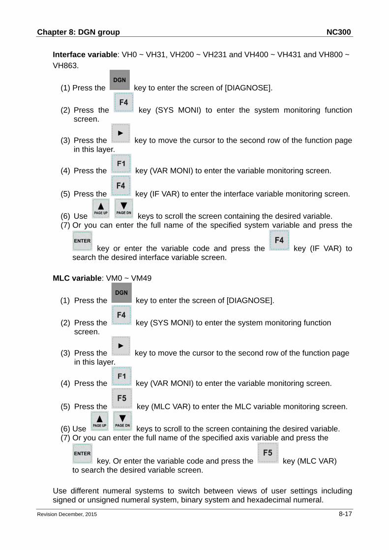
Chapter 8: DGN group NC300
Revision December, 2015 8-17
Interface variable: VH0 ~ VH31, VH200 ~ VH231 and VH400 ~ VH431 and VH800 ~
VH863.
(1) Press the key to enter the screen of [DIAGNOSE].
(2) Press the key (SYS MONI) to enter the system monitoring function screen.
(3) Press the key to move the cursor to the second row of the function page in this layer.
(4) Press the key (VAR MONI) to enter the variable monitoring screen.
(5) Press the key (IF VAR) to enter the interface variable monitoring screen.
(6) Use keys to scroll the screen containing the desired variable. (7) Or you can enter the full name of the specified system variable and press the
key or enter the variable code and press the key (IF VAR) to search the desired interface variable screen.
MLC variable: VM0 ~ VM49
(1) Press the key to enter the screen of [DIAGNOSE].
(2) Press the key (SYS MONI) to enter the system monitoring function screen.
(3) Press the key to move the cursor to the second row of the function page in this layer.
(4) Press the key (VAR MONI) to enter the variable monitoring screen.
(5) Press the key (MLC VAR) to enter the MLC variable monitoring screen.
(6) Use keys to scroll to the screen containing the desired variable. (7) Or you can enter the full name of the specified axis variable and press the
key. Or enter the variable code and press the key (MLC VAR) to search the desired variable screen.
Use different numeral systems to switch between views of user settings including signed or unsigned numeral system, binary system and hexadecimal numeral.

NC300 Chapter 8: DGN group
8-18 Revision December, 2015
8.5 Password setting This function enables users to set up different permission levels for the system (system maintenance), equipment (mechanical equipment) and users (operation and use). It prevents unauthorized users from changing system settings.
8.5.1 System permission
The system permission function covers permission lock, permission unlock and system check. The password is composed of up to four alphanumeric characters (symbols excluded). See the operation steps below for permission lock and unlock:
(1) Press the key to enter the screen of [DIAGNOSE].
(2) Press the key (PWD) to enter the password setup function bar.
(3) Press the key (S SCP) to enter the system permission lock/unlock function bar.
(4) If the system permission is unlocked, press the key (LOCK) to lock system permission.
(5) If the system permission is locked, press the key (UNLOCK) and an entry dialog box will pop up for users to enter permission password.
(6) Enter a valid password and press the key to unlock the permission.
Steps to inspect the system:
(1) Press the key to enter the screen of [DIAGNOSE].
(2) Press the key (PWD) to display the password setup function bar.
(3) Press the key (S SCP) to enter the system permission lock/unlock function bar.
(4) When the system permission is unlocked, press the key (SYS CHECK) to see if there is any error occurs. If the item is checked, an error is found under the checked item.

Chapter 8: DGN group NC300
Revision December, 2015 8-19
8.5.2 Equipment permission This function covers password change, permission lock, permission unlock, user 1 reset and user 2 reset. The password is composed of up to four alphanumeric characters (symbols excluded). See the operation steps below for changing equipment permissions:
(1) Press the key to enter the screen of [DIAGNOSE].
(2) Press the key (PWD) to enter the password setup function bar.
(3) Press the key (M SCP) to enter the equipment permission function bar.
(4) Press the key (PWD CHG) and an entry dialog box will pop up as shown in Figure 8-5-1. Enter old password, new password, and new password again (for confirmation) as prompted.
(5) Enter the passwords as prompted and press the key.
Figure 8-5-1

NC300 Chapter 8: DGN group
8-20 Revision December, 2015
See the operation steps below for equipment permission resetting:
(1) Press the key to enter the screen of [DIAGNOSE].
(2) Press the key (PWD) to enter the password setup function bar.
(3) Press the key (M SCP) to enter the equipment permission function bar.
(4) Press the key (UNLOCK) and an entry dialog box will pop up for users to enter the password when equipment permission is locked.
(5) Enter a valid password and press the key to revoke the equipment permission.
Note:
The default password of equipment permission is 0000, which means the permission is unlocked and all functions can be accessed. When the password is changed, the equipment permission is enabled and it means the related functions can be accessed with the permission only.
See the operation steps below for equipment permission lock up:
(1) Press the key to enter the screen of [DIAGNOSE].
(2) Press the key (PWD) to enter the password setup function bar.
(3) Press the key (M SCP) to enter the equipment permission function bar.
(4) Press the key (LOCK) to lock permission when it is revoked.

Chapter 8: DGN group NC300
Revision December, 2015 8-21
User reset function allows the equipment supplier to reset the user’s password. Once the client forgets the password, the equipment supplier is able to reset as the default password. This function is active only when the password is not the default value. See below for the operation steps.
(1) Press the key to enter the screen of [DIAGNOSE].
(2) Press the key (PWD) to display the password setup function bar.
(3) Press the key (M SCP) to display the equipment permission function bar.
(4) Press key (RST U1) / key (RST U2) to reset the user’s password.
Function Enabled is to enable/disable the group function. Once the group is
canceled, the function will be disabled after the system is re-started up. See below
for the operation steps.
(1) Press the key to enter the screen of [DIAGNOSE].
(2) Press the key (PWD) to display the password setup function bar.
(3) Press the key (M SCP) to display the equipment permission function bar.
(4) Press the key (ENABLE) to enter the setting screen to enable the group function.
(5) Use keys to move the cursor to the field to be cancelled. Press the
key to cancel the selection. Then, press the key once the setting is done. The setting will take effect after the system is re-started up.
(6) If you wish to cancel the group function, press the key (CANCEL) to exit the the setting page of group function.
(7) If you wish to restore the system to the default setting, press the key (DEFAULT) to restore the system to the initial setting of group function.

NC300 Chapter 8: DGN group
8-22 Revision December, 2015
Figure 8-5-2
Restore Function
When the numerical control system has any error or the system data is seriously
damaged, this function enables users to restore the damaged data through system
backup. Users need to enter the restore screen to select the item to be restored.
Please note that permission is required to apply this function. See below for the operation steps:
(1) Press the key to enter the screen of [DIAGNOSE].
(2) Press the key (PWD) to display the password setup function bar.
(3) Press the key (M SCP) to display the equipment permission function bar.
(4) Press the key (RESTORE) and enter the screen to select the item to
be restored. Use keys to move the cursor. Then, press
the key to select the item to be restored.
(5) To cancel the selection: Press the key on the checked iem to cancel the selection.
(6) Press the key (OK) to restore the system.

Chapter 8: DGN group NC300
Revision December, 2015 8-23
8.5.3 User permission Users can set up User permission 1 and User permission 2. The permission function covers password change (PWD CHG), user account lockup (LOCK) and user account unlocking (UNLOCK). The password is composed of up to four alphanumeric characters (symbols excluded). See the operation steps described below for changing user password (illustrated with User permission 1):
(1) Press the key to enter the screen of [DIAGNOSE].
(2) Press the key (PWD) to enter the password setup function bar.
(3) If [User permission 1] is locked, press the key (U1 SCP) and the password entry dialog box for unlocking [User permission 1] will pop up.
(4) Enter valid password and press the key to to unlock [User permission 1] and display relevant function items.
(5) Press the key (PWD CHG) and an entry dialog box pops up for users to enter old password once and new password twice for confirmation.
(6) Enter passwords as prompted and press the key to complete the setting.

NC300 Chapter 8: DGN group
8-24 Revision December, 2015
See the operation steps below for unlocking the user account:
(1) Press the key to enter the screen of [DIAGNOSE].
(2) Press the key (PWD) to display the password setup function bar.
(3) When [User permission 1] is locked, press the key (U1 SCP) and the password entry dialog box for unlocking [User permission 1] will pop up.
(4) Enter the valid password for [User permission 1]. Press the key to unlock and display relevant function items.
See the operation steps described below for user permission lockup:
(1) Press the key to enter the screen of [DIAGNOSE].
(2) Press the key (PWD) to display the password setup function bar.
(3) When [User permission 1] is unlocked, press the key (U1 SCP) to display relevant function items.
(4) Press the key (LOCK) to lock [User permission 1].
Note: The function of user permission is the same as equipment permission. Its default password is 0000, which means all functions are available. If the user password is changed, the user permission is enabled.

Chapter 8: DGN group NC300
Revision December, 2015 8-25
8.5.4 Timed use Users can assign a timed use of the controller to limit its use in a set period of time. The system controls given days or hours for the use of the controller automatically. Users can unlock or reset the time limit only with valid permission when the time limit is active. The "deadline" in the time limit screen remains blank when no time limit is set or the limit is unlocked as shown in Figure 8-5-3. If there is an active time limit in existence and it is locked, the "deadline" in the time limit screen indicates a valid due date as shown in Figure 8-5-4:
Figure 8-5-3
Figure 8-5-4
This screen helps users to know to which date the controller can be used normally. After the due date, the system will be locked unless the time limit is unlocked or extended to a later date. Otherwise, no G code program can be executed manually or automatically. Please contact the dealer/service provider in case it is overdue.

NC300 Chapter 8: DGN group
8-26 Revision December, 2015
This function enables users to set up a time limit when there is no time limit in existence. See the operation steps described below for time limit setup:
(1) Press the key to enter the screen of [DIAGNOSE].
(2) Press the key (PWD) to enter the password setup function bar.
(3) Press the key (EXPIRE) to display the time limit information.
(4) Press the key (SETTING) to enter the limit setup page. (5) After entering the password of legal permission, the system’s time limit control is
activated.
See the operation steps described below for revoking a time limit. Please contact the dealer/service provider for further information.
(1) Press the key to enter the screen of [DIAGNOSE].
(2) Press the key (PWD) to enter the password setup function bar.
(3) Press the key (EXPIRE) to display the remaining time information.
(4) Press the key (RELEASE) and a dialog box will pop up that requires users to enter the start code. See Figure 8-5-5.
Figure 8-5-5
(5) With proper authorization, enter the start code and press the key. Then, restart the system, the time limit is now unlocked.

Chapter 8: DGN group NC300
Revision December, 2015 8-27
Note: After the time limit is unlocked, the "deadline" field turns blank, as shown in Figure 8-5-6. The screen indicates that the system does not have a time limit set up.
Figure 8-5-6
The management of time limit permission must go through the proper authorization to lock or unlock the time limit permission. When the time limit is activated, only when entering the correct password can the permission be unlocked. After the permission is unlocked, all time limit function is available, including password change and permission lock/unlock. The password is composed of up to 4 alphanumeric characters (symbol excluded). See the operation steps described below for changing the password of time limit.
(1) Press the key to enter the screen of [DIAGNOSE].
(2) Press the key (PWD) to enter the password setup function bar.
(3) Press the key (EXPIRE) to display the remaining time information.
(4) When the permission is locked, press the key (EXP SCP) and the password entry dialog box will pop up for unlocking time limit.
(5) Enter the valid password for time limit permission and press the key to unlock time limit permission and display relevant function items.
(6) Press the key (PWD CHG), and an entry dialog box will pop up for users to enter old password once and new password twice for confirmation.
(7) Enter passwords as prompted and press the key.

NC300 Chapter 8: DGN group
8-28 Revision December, 2015
See the operation steps described below for revoking the time limit permission.
(1) Press the key to enter the screen of [DIAGNOSE].
(2) Press the key (PWD) to enter the password setup function bar.
(3) Press the key (EXPIRE) to display the remaining time information.
(4) When the permission is locked, press the key (EXP SCP) and the password entry dialog box will pop up for unlocking time limit permission.
(5) Enter the valid password for time limit permission. Then, press the key to unlock the time limit permission and display relevant function items.
See the operation steps described below for locking the time limit permission.
(1) Press the key to enter the screen of [DIAGNOSE].
(2) Press the key (PWD) to enter the password setup function bar.
(3) Press the key (EXPIRE) to display the remaining time information.
(4) When the permission is unlocked, press the key (EXP SCP) for displaying the relevant function items.
(5) Press the key (LOCK) and resume the permission lock.

Chapter 8: DGN group NC300
Revision December, 2015 8-29
8.6 System information This function provides hardware and firmware program version of this system for system maintenance and performance optimization. It covers the options of system status, hardware and firmware serial number and equipment information. See the operation steps described below for system status display:
(1) Press the key to enter the screen of [DIAGNOSE].
(2) Press the key (STATUS) to enter the screen of system information.
(3) Press the key (SYSTEM) to enter the screen of system status information.
The firmware serial number function displays the firmware version number as well. See the operation steps described below:
(1) Press the key to enter the screen of [DIAGNOSE].
(2) Press the key (STATUS) to enter the screen of system information.
(3) Press the key (FW SN) to display firmware version information as shown in the figure below.
Figure 8-6-1

NC300 Chapter 8: DGN group
8-30 Revision December, 2015
See the operation steps described below for hardware serial number display:
(1) Press the key to enter the screen of [DIAGNOSE].
(2) Press the key (STATUS) to enter the screen of system information.
(3) Press the key (HW SN) to display hardware version information.
See the operation steps described below for equipment information display:
(1) Press the key to enter the screen of [DIAGNOSE].
(2) Press the key (STATUS) to enter the screen of system information.
(3) Press the key (M STATUS) to display the equipment information.
(4) Users can enter the equipment information in this page or press the key (DEL) to delete the equipment information where the cursor indicates.

Chapter 8: DGN group NC300
Revision December, 2015 8-31
8.7 Gain adjustment The auto gain adjustment enables the system and the servo drive to work out even better motion control to meet different mechanical requirements of various machines. The NC300 controller accesses initial parameters of the servo and calibrates motion control with gain adjustment function. Then, it will send the result to the servo drive for unifying the control parameters of the controller and the servo drive. This brings the convenient when adjusting the gain and enhances the control accuracy for the system. Sub menu items of this function are described with the function screen as shown in the figure below.
Next axis: This function switches axial gain settings. The auto gain can be adjusted by individual axis. After the first axis is adjusted, users need to switch to the next one for its adjustment. See the operation steps described below:
(1) Press the key to enter the screen of [DIAGNOSE].
(2) Press the key to enter the next function page.
(3) Press the key (TUNING) to enter the auto gain setup page.
(4) Press the key (NEX AX) to switch to the next axis for its axial gain parameters setup.
Servo parameter ID Servo parameter ID and name
Anchor point setupAnchor point 1/ Anchor point 2
Adjustment conditions
Calculated results after adjustments Display calculated results after auto gain
Existing settings of the
system
Indicates servo settings
currently used by the
system

NC300 Chapter 8: DGN group
8-32 Revision December, 2015
Read the Servo: After the auto gain adjustment function is activated, its parameter values have been synchronized with those of the servo. To accommodate the function of gain adjustment, the calculated results after auto gain operation are not written back to the servo. This function can be used to restore servo parameters. See the operation steps described below:
(1) Press the key to enter the screen of [DIAGNOSE].
(2) Press the key to switch to the next function page.
(3) Press the key (TUNING) to enter the auto gain setup page.
(4) Press the key (READ) to access parameter values from the servo.
Start, Jog←, Jog→, Positioning 1, Positioning 2: This sets up the operation of auto gain adjustment. It starts auto gain adjustment and sets up the positioning direction and operation. See the operation steps described below for continuous operation (Single-axis operation):
(1) Press the key to enter the screen of [DIAGNOSE].
(2) Press the key to switch to the next function page.
(3) Press the key (TUNING) to enter the auto gain setup page.
(4) Press the key to switch to the next function page.
(5) Press the key (JOG ←) to move to the left positioning point.
(6) Press the key (POS 1) to set the left positioning point.
(7) Press the key (JOG →) to move to the right positioning point.
(8) Press the key (POS 2) to set the right positioning point. The movement is now limited between both points.
(9) Press the key (RUN) to execute gain adjustment.
(10) Press the key (STOP) during auto adjustment. Then, the system will automatically calculate the best gain value.

Chapter 8: DGN group NC300
Revision December, 2015 8-33
Gain calculation: Users can change low-frequency rigid, bandwidth, or inertia ratio to fit individual machines. These values can be generated by this function automatically. See the operation steps described below for single axis operation:
(1) Press the key to enter the screen of [DIAGNOSE].
(2) Press the key to switch to the next function page.
(3) Press the key (TUNING) to enter the auto gain setup page.
(4) Use keys to move the cursor to the low-frequency rigid, bandwidth, or inertia ratio fields for entering settings respectively.
(5) Press the key (COMPUTE) to generate new gain values.
Gain and resonance write-in: New gain values are generated after the auto gain adjustment has stopped. If they are the expected optimization values, please use this function to write them in the servo drive. See the operation steps described below:
(1) Press the key to enter the screen of [DIAGNOSE].
(2) Press the function key to switch to the next function page.
(3) Press the key (TUNING) to enter the auto gain setup page. (4) Gain values are generated automatically after gain adjustment is complete.
(5) Press the key (WR GAIN) to write gain values in the servo drive. Then,
press the key (WR NOTH) to write resonance suppression values in the servo drive.
Note: (a) The newly generated gain adjustment results must be written in the servo
drive before it can take effect. (b) After gain and resonance write-in function is executed, the servo parameters
are updated and the old ones cannot be recovered. Please do the write-in with care.

NC300 Chapter 8: DGN group
8-34 Revision December, 2015
Tapping adjustment: This function fine tunes the machine and servo for tapping application. See the operation steps described below:
(1) Press the key to enter the screen of [DIAGNOSE].
(2) Press the key to switch to the next function page.
(3) Press the key (TUNING) to enter the auto gain setup page.
(4) Complete X-, Y- and Z-axis and spindle's gain adjustment first.
(5) Repeatedly press the key to enter the last page.
(6) Press the key (TAP RIV) to switch to the operation screen.
(7) Press the key (TAP SET) again and the confirmation dialog box will pop
up. Press Y (Yes) key and press the key to fine tune the machine for tapping.
Servo parameter: This function sets up the parameter for servo parameter display and setup in the gain adjustment screen:
(1) Press the key to enter the screen of [DIAGNOSE].
(2) Press the key to switch to the next function page.
(3) Press the key (TUNING) to enter the auto gain setup page.
(4) Repeatedly press the key to enter the last page.
(5) Press the key (SERVO) to enter the servo parameter screen. (6) Move the cursor to the specified field and type in relevant data. Then, press the
key to set up a given field.

Chapter 8: DGN group NC300
Revision December, 2015 8-35
Synchronized control: This function can be applied when users need to synchronously control the master axis and slave axis. Before enabling this function, users have to complete the setting of parameters and channel. See the operation steps described below:
(1) Firstly, complete the setting of parameter 361 ~ 366 and channel axis.
(2) Press the key to enter the screen of [DIAGNOSE].
(3) Press the key to switch to the next function page.
(4) Press the key (TUNING) to enter the auto gain setup page.
(5) Repeatedly press the key to enter the last page.
(6) Press the key (SYN) to switch to the operation screen.
(7) Then, press the key (POS SET) to complete the setting.

NC300 Chapter 8: DGN group
8-36 Revision December, 2015
8.8 Import The system features a parameter import/export function for managing system parameters. Users can import correct parameters recover the system and export the modified parameter files for backup. This function can only be used with proper permissions. It can efficiently troubleshoot the system with parameter errors.
See the operation steps described below for parameter import:
(1) Press the key to enter the screen of [DIAGNOSE].
(2) Press the key to switch to the next function page.
(3) Press the key (IMPORT) to display window of [FILE] (see Figure 8-8-1).
Use keys to select the file path and press the key to access the file.
Figure 8-8-1
(4) Use keys to move the cursor. Press the key to check the parameter items to be imported.
(5) Press the key (SEL ALL) to select all or press the key (CLR ALL) to cancel the selected items to be imported.
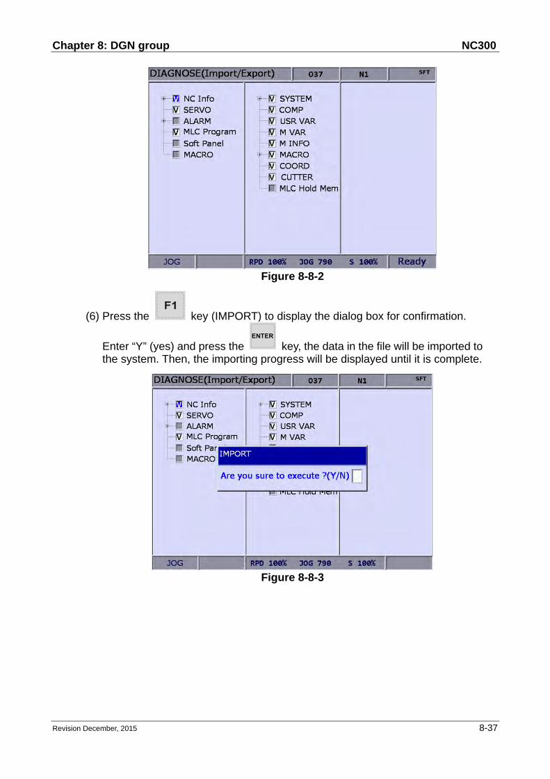
Chapter 8: DGN group NC300
Revision December, 2015 8-37
Figure 8-8-2
(6) Press the key (IMPORT) to display the dialog box for confirmation.
Enter “Y” (yes) and press the key, the data in the file will be imported to the system. Then, the importing progress will be displayed until it is complete.
Figure 8-8-3

NC300 Chapter 8: DGN group
8-38 Revision December, 2015
8.9 Export Export function: System parameters may be modified to meet the requirements of different applications. After the system is optimized, this function can be used to export parameter values for backup and control. The exported file type includes parameter file, MLC and software panel. Please note that this function can be used only with proper permissions.
See the operation steps described below for parameter export:
(1) Press the key to enter the screen of [DIAGNOSE].
(2) Press the key to switch to the next function page.
(3) Press the key (EXPORT) to enter the screen of parameter export selection.
(4) Use keys to move the cursor. Press the key
to check the items to export. Users may press the key (SEL ALL) to
select all or press the key (CLR ALL) to cancel all the sleceted items to export.
Type Filename Descriptions
Parameter
file PAR.ncp NC information, servo parameters and alarms
MLC MLC.gmc MLC code
MLC MLC.lad Image file of MLC Ladder
MLC MLC.lcm Comments of MLC Ladder
Software
panel HMI.cin
Screen information and element property of the
software panel
Software
panel HMI.img Image file of software panel
Software
panel HMI.sci Project of software panel

Chapter 8: DGN group NC300
Revision December, 2015 8-39
Figure 8-9-1
(5) Press the key (EXPORT) to display the window of [FILE] (see Figure
8-9-2). Use keys to select the file path of the saving destination or
directly enter the file path in the directory. Then, press the to save the exported data in the specified data file.
Figure 8-9-2
(6) After confirmed, the exporting progress will be shown before it is complete.
(7) To create a new file and save the exported data to this file (see Figure 8-9-2),
please name this file and then press the key (FOLDER) to save the data.

NC300 Chapter 8: DGN group
8-40 Revision December, 2015
(8) If the destination already contains an exported data file, a popup window will display “Update backup folder! Are you sure to execute?”. Press “Y” (yes) and
then press the key to replace the existing data file.
Figure 8-9-3
(9) In addition, the file management function [FILE] can be operated by related function keys. (See Figure 8-9-2)

Chapter 8: DGN group NC300
Revision December, 2015 8-41
8.10 Multi language download
Language support of the group screens and function bars includes both Chinese and English. For other language support, please enhance the interface language with this multi-language downloading function. Please contact the dealer/service provider for details.
8.11 LOGO download The startup screen of the system can be customized with user exclusive contents for logo presentation or other uses with this function. This function can be used only with proper permissions. See the operation steps described below:
(1) Press the key to enter the screen of [DIAGNOSE].
(2) Repeatedly press the key to enter the function bar for displaying the next page.
(3) Insert a USB drive containing the correct NC300 system startup screen file.
(4) Press the key (LOGO WR), a dialogue box will pop up. (5) Enter “Y”. It automatically accesses and loads in the start-up file from the USB. (6) Restart the system after the LOGO image file is updated.

NC300 Chapter 8: DGN group
8-42 Revision December, 2015
(This page is intentionally left blank.)

Chapter 9: PAR Group NC300
Revision December, 2015 9-1
Chapter 9: PAR group
PAR Group regulates and sets up a full range of system control and computing parameters for easy management and optimized setup. The PAR group covers the setup of parameters for operation, tool magazine, machining, spindle, mechanical, origin, compensation, and system. After completing the parameter setting, please validate the setting according to their parameter types. There are three types: S: Power-off the servo drive; P: Power-off the system; R: Press the RESET key.
9.1 Machining parameter The machining parameter sets up parameters for the maximum cutting speed, cutting and smoothing acceleration and deceleration time. These parameters bring a huge impact on machining quality. For the best operation effect, please set up these parameters based on actual requirements. See the operation steps below:
(1) Press the key to enter the screen of [PARAMETER].
(2) Press key (Process) to enter the screen of machining parameter setup.
(3) Use keys to move the cursor to the desired data field, and enter the proper values (Refer to the recommended values displayed at lower right corner of the screen) as shown in Figure 9-1-1.
(4) Press the key to complete the setting.
Figure 9-1-1

NC300 Chapter 9: PAR Group
9-2 Revision December, 2015
9.2 Operation parameter Users can combine the execution and computing of a macro program in the G code file for composite motions. Users also can control or execute the execution of a macro program in the screen of [PARAMTER (Operation)]. See the operation steps below:
(1) Press the key to enter the screen of [PARAMETER].
(2) Press the key (Operate) to enter the operation parameter setup screen.
(3) Use keys to move the cursor to the desired data field, and enter the proper values (Refer to the recommended values displayed at lower right corner of the screen) as shown in Figure 9-2-1.
(4) Press the key to complete the setting.
Figure 9-2-1
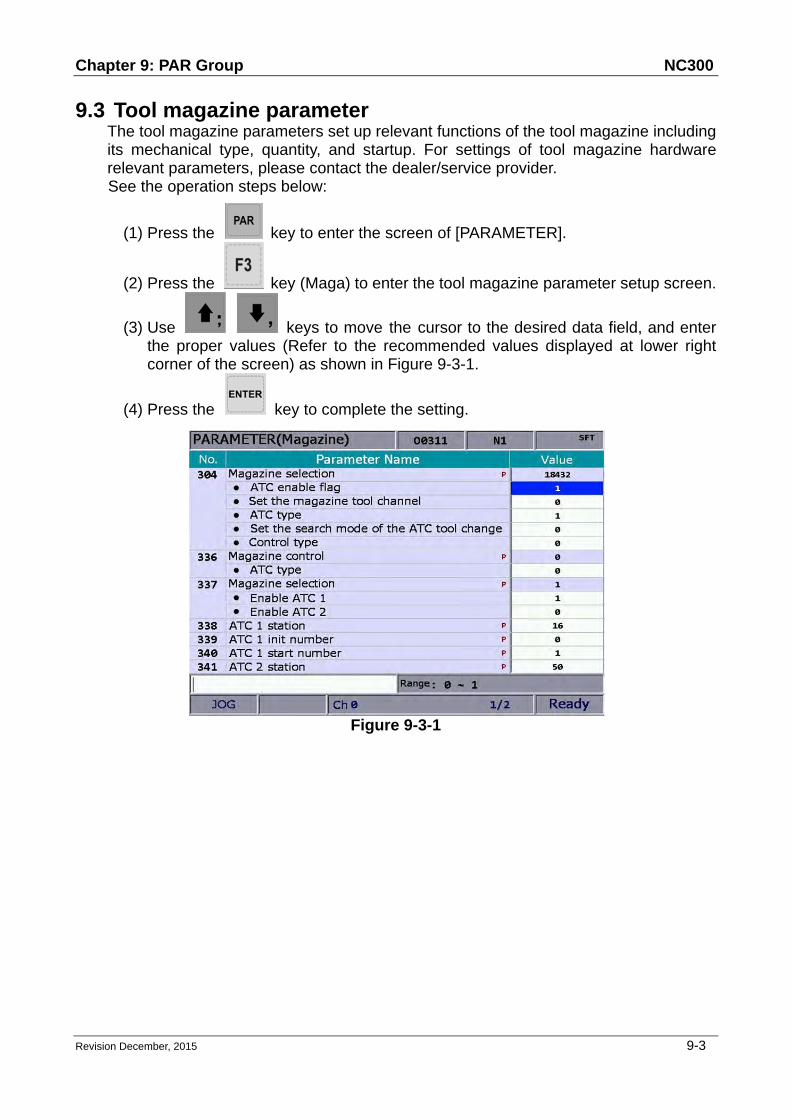
Chapter 9: PAR Group NC300
Revision December, 2015 9-3
9.3 Tool magazine parameter The tool magazine parameters set up relevant functions of the tool magazine including its mechanical type, quantity, and startup. For settings of tool magazine hardware relevant parameters, please contact the dealer/service provider. See the operation steps below:
(1) Press the key to enter the screen of [PARAMETER].
(2) Press the key (Maga) to enter the tool magazine parameter setup screen.
(3) Use keys to move the cursor to the desired data field, and enter the proper values (Refer to the recommended values displayed at lower right corner of the screen) as shown in Figure 9-3-1.
(4) Press the key to complete the setting.
Figure 9-3-1

NC300 Chapter 9: PAR Group
9-4 Revision December, 2015
9.4 Spindle parameter The spindle parameters set up various spindle function including gains, maximum speed, and positioning errors. See the operation steps below:
(1) Press the key to enter the screen of [PARAMETER].
(2) Press the key (Spindle) to enter the spindle parameter setup screen.
(3) Use keys to move the cursor to the desired data field and enter the proper values (Refer to the recommended values displayed at lower right corner of the screen) as shown in Figure 9-4-1.
(4) Press the key to complete the setting.
Figure 9-4-1

Chapter 9: PAR Group NC300
Revision December, 2015 9-5
9.5 Mechanical parameter Users can set up the mechanical equipment relevant parameters of software/hardware limit, screw guide pitch and number of pulses of encoder. See the operation steps below:
(1) Press the key to enter the screen of [PARAMETER].
(2) Press the key (Machine) to enter the mechanical parameter setup screen.
(3) Use keys to move the cursor to the desired data field and enter the proper values (Refer to the recommended values displayed at lower right corner of the screen) as shown in Figure 9-5-1.
(4) Press the key to complete the setting.
Figure 9-5-1

NC300 Chapter 9: PAR Group
9-6 Revision December, 2015
9.6 Origin parameter The origin parameter sets up coordinates from mechanical origin to the fourth reference point and origin searching mode. See the operation steps below:
(1) Press the key to enter the screen of [PARAMETER].
(2) Press the key (Home) to enter the origin parameter setup screen.
(3) Use keys to move the cursor to the desired data field and enter the proper values (Refer to the recommended values displayed at lower right corner of the screen) as shown in Figure 9-6-1.
(4) Press the key to complete the setting.
Figure 9-6-1

Chapter 9: PAR Group NC300
Revision December, 2015 9-7
9.7 Network Setup This function enables users to remotely connect to a PC through Ethernet communication. Working together with CNC Network software and the network setting of the NC300 numerical control system, users can use one PC to control multiple NC300 controllers for online file management, file sharing, file management and transmission-along-with-machining (DNC) through remote network communication. See the operation steps below:
(1) Press the key to enter the screen of [PARAMETER].
(2) Press the key to switch to the screen with function bar.
(3) Press the key (Network Set) to enter the network setup page.
(4) Use keys to move the cursor to the desired data field and enter the proper values (Refer to the recommended values displayed at lower right corner of the screen) as shown in Figure 9-7-1.
(5) Press the key to complete the setting.
Figure 9-7-1

NC300 Chapter 9: PAR Group
9-8 Revision December, 2015
9.8 Compensation parameter The compensation parameter sets up relevant compensation data to compensate errors caused by mechanical factors during actual machine operation. That is to say, the compensation is given by the control system with considering the machine features. See the operation steps below:
(1) Press the key to enter the screen of [PARAMETER].
(2) Press the key to switch to the screen with function bar.
(3) Press the key (Comp) to enter the compensation parameter setup screen.
(4) Use keys to move the cursor to the desired data field and enter the proper values (Refer to the recommended values displayed at lower right corner of the screen) as shown in Figure 9-8-1.
Figure 9-8-1
(5) Press the key to complete the setting.
(6) Press the key (um) to complete the setting of absolute length
compensation in unit of um; or press the key (um+) to complete the setting of incremental length compensation in unit of um.
(7) Compensation data generated by calibration instruments can be converted by
the CNC SOFT program. Press the key (import) to import compensation
data in absolute type; or press the key (import +) to import

Chapter 9: PAR Group NC300
Revision December, 2015 9-9
compensation data in incremental type.
(8) After entering all compensation value, press the key (OK) to confirm and update the compensation parameters.
9.9 System parameter The system parameters enable users to customize operation environment including system date, system time, background color of screen, function bar color, and tab color. See the operation steps below:
(1) Press the key to enter the screen of [PARAMETER].
(2) Press the key to switch to the screen with function bar.
(3) Press the key (System) to enter the system parameter setup screen.
(4) Use keys to move the cursor to the desired data field and enter the proper values (Refer to the recommended values displayed at lower right corner of the screen) as shown in Figure 9-9-1.
Figure 9-9-1
(5) Press the key to complete the setting.
(6) As for the setting of color items, press the key (Color) and the color selection dialog box will pop up.
(7) To reset the system environment back to its factory defaults status, press the
key (Default) and a confirmation dialog box will pop up.
(8) Press "Y" (Yes) and the key to reset the system back to its factory

NC300 Chapter 9: PAR Group
9-10 Revision December, 2015
defaults status.
9.10 MLC setting This function sets up the display environment of the component device and color of the MLC ladder diagram. See the operation steps below:
(1) Press the key to enter the screen of [PARAMETER].
(2) Press the key to switch to the screen with function bar.
(3) Press the key (MLC) to enter the MLC setup screen.
(4) Use keys to move the cursor to the desired data field and enter the proper values (Refer to the recommended values displayed at lower right corner of the screen) as shown in Figure 9-10-1.
Figure 9-10-1
(5) Press the key to complete the setting.
(6) As for the setting of color item, press the key (Color) and the color selection dialog box will pop up.
(7) To reset the system environment back to its factory defaults status, press the
key (Default) and a confirmation dialog box will pop up.
(8) Press "Y" (Yes) and the key to reset the system back to its factory defaults status.

Chapter 9: PAR Group NC300
Revision December, 2015 9-11
9.11 Graph parameter The graph parameter defines the display range of motion trails and provides plotting settings for GRA group.
Figure 9-11-1
See the operation steps below:
(1) Press the key to enter the screen of [PARAMETER].
(2) Press the key to switch to the screen with function bar.
(3) Press the key (Graphic) to enter the graph parameter setup screen.
(4) Use keys to move the cursor to the desired data field and enter the proper values (Refer to the recommended values displayed at lower right corner of the screen) as shown in Figure 9-11-1.
(5) Press the key to complete the setting.
(6) As for the setting of color item, press the key (Color) and the color selection dialog box will pop up.
(7) To reset the system environment back to its factory defaults status, press the
key (Default) and a confirmation dialog box will pop up.
(8) Press "Y" (Yes) and the key to reset the system back to its factory defaults status.

NC300 Chapter 9: PAR Group
9-12 Revision December, 2015
9.12 Servo parameter Through the servo parameter setup screen, the servo end can control and set up parameters. See the operation steps below:
(1) Press the key to enter the screen of [PARAMETER].
(2) Press the key to switch to the screen with function bar.
(3) Press the key (Servo) to enter the servo parameter setup screen.
(4) Use keys to move the cursor to the desired data field and enter the proper values (Refer to the recommended values displayed at lower right corner of the screen).
(5) Press key to complete the setting.
Figure 9-12-1

Chapter 9: PAR Group NC300
Revision December, 2015 9-13
9.13 Channel setup This function sets up the number and definition of the axis employed by a system as shown in Figure 9-13-1. The system mode cannot be set up in Auto and Manual modes.
Figure 9-13-1
See the operation steps below:
(1) Press the key to enter the screen of [PARAMETER].
(2) Repeatedly press the key to move the cursor to the third row of the function page in this layer.
(3) Press the key (Config) to enter the screen for channel setup.
(4) Use keys to move the cursor to the desired axis function fields,
and then press the key to select the axis and enable its attribute setting. Users can select the axis attribute of either NC or MLC as desired.
(5) To define axis attributes: Use keys to move the
cursor to the desired field and press the key to check the field.
(6) After the axis attribute is defined, use keys to move
the cursor to the port field of the axis, press the key and the port number
entry box for setting up the port number will pop up, Then, press ~

NC300 Chapter 9: PAR Group
9-14 Revision December, 2015
keys to enter a unique port number, press the key and the port number of the axis is set.
(7) Press the key (OK) after all axes are defined. (8) Restart the NC300 control system to validate the setting.
Note: (a) Please check to activate the axis name before enabling the axis. Users can
set up the definition to control the axis only after it is activated. Select either the NC or MLC axis (not both), and assign a port number (unique from other axis port numbers).
(b) To disable (cancel) the axis function, move the cursor to the specified field and press the ENTER key to uncheck the item. Then the function of this axis will be disabled.
(c) Parameter fields marked with the letter 'P' indicates that changes can take effect only after the NC300 control system is restarted. Otherwise, changes take effect immediately.

Chapter 9: PAR Group NC300
Revision December, 2015 9-15
9.14 RIO setting The NC300 numerical control system can have external control switch by increasing the I/O expansion module. The I/O function module can be enabled in RIO setting page as shown in Figure 9-14-1. See the operation steps below:
Figure 9-14-1
(1) Press the key to enter the screen of [PARAMETER].
(2) Repeatedly press the key to move the cursor to the third row of the function page in this layer.
(3) Press the key (Set RIO) to enter the I/O expansion module setup page.
(4) Use keys to move the cursor to the desired RIO port fields, press
the key to check the field and display the I/O setup screen of the selected port.
(5) Use keys to move the cursor to the polarity setup field, press the
key and the entry box will pop up. Then, press the key after data entry and the polarity is set.
(6) Then, use keys to move to the field of [Disc.] (output when
disconnected), press the key to enable/disable the setting.

NC300 Chapter 9: PAR Group
9-16 Revision December, 2015
(7) Press the key (OK) after all I/O modules function are set.
9.15 Search This function enables users to search and point to the desired parameter fields by entering parameter codes. It is faster and easier to access to the screen containing the given parameter. See the operation steps below:
(1) Press the key to enter the screen of [PARAMETER].
(2) Repeatedly press the key to move the cursor to the third row of the function page in this layer.
(3) Enter the parameter code to be searched in the field located at the lower bottom of the screen.
(4) Press the key (Search) to start searching.
Note: Apart from using the function key to search the parameter, users can enter the parameter number in the screen of PAR group. The method is: S + parameter number and then press the ENTER key.

Chapter 9: PAR Group NC300
Revision December, 2015 9-17
9.16 Parameter group
The NC300 numerical control system provides many types of parameters. Users
can define the customized parameter group function and select the appropriate
parameter groups according to different demands and applications. See Figure
9-16-1 below.
Figure 9-16-1
See the operation steps below:
(1) Press the key to enter the screen of [PARAMETER].
(2) Repeatedly press the key to move the cursor to the third row of the function page in this layer.
(3) Press the key (PAR GROUP) to enter the parameter group setup page.
(4) Enter the specified parameter number in the field of [Number] and press the
key. Then, parameter name will appear on the screen.
(5) Press the key (PAR SEQUENCE) and the parameter number on this
setting page will show in sequence. Press the key (PAR SEQUENCE)
to display the parameter number from small > big. Press the key (PAR SEQUENCE) again, the parameter number will be displayed from big to small.

NC300 Chapter 9: PAR Group
9-18 Revision December, 2015
(6) Use keys to move the cursor to the desired group field and
press the key to complete the setting of parameter group. Or press the
key (READ PAR) when the cursor stops at the field of [GROUP], a confirmation box of reading the parameter will pop up. Then, press “Y” (Yes)
and press the key again to read the parameter value.
(7) If you wish to delete the parameter group, use keys to move the
cursor to the desired group field, press the key (DEL GROUP) and a
confirmation box of “Delete the group” will pop up. Press “Y” and the key to delete the group.
(8) When entering multiple parameter groups, press the key (ALLOCATE)
and a confirmation box will pop up. Press “Y” and the key. The system will divide the range of parameter value by the group number. Then the parameter value will be allocated to each group that you currently applied.
(9) After completing the setting of parameter group, press the key (SAVE) to see the setting screen and result and a confirmation box will pop. Then,
press “Y” (Yes) and press the key again to save the setting.
(10) Use keys to move the cursor to the specified group field
and press the key (WRITE PAR). A confirmation box will then pop up.
Press “Y” and the key again to write the value to the corresponding parameters.
Note:
(a.) Writing the value to parameters will replace the original parameter value in
the system. Please make sure the parameter value is correct beforehand.
(b.) Up to 20 groups with maximum 20 parameters for each group are
supported.

Chapter 10: SOFT group NC300
Revision December, 2015 10-1
Chapter 10: SOFT group
SOFT group is a special control function provided by NC300 numerical controller to replace the physical secondary control panel or special operation functions. With the CNC SOFT software, users can add a secondary control panel screen and use it to do exactly the operations available in the physical secondary control panel. This function can be used in environments without physical secondary control panel to support special repair servicing needs. Users may use it to add software keys with self-developed special controls for expanded functionality. This group function can replace the physical secondary control panel's control or function options.
10.1 Control panel (※Example: without physical operation panel)
See Figure 10-1-1 for an example of the function devices offered by this function. Keys and buttons of a physical secondary control panel are simulated with control components. Each device is turned on or off with relevant function key. Device types and priorities vary with user preference. Icons are sorted from bottom to top. See the operation steps below for the operation of the control panel:
(1) Press the key to enter the SOFT group screen.
(2) Press the key (control panel) to enter the device function bar screen.
(3) Use keys to access the corresponding device function page as shown in Figure 10-1-1.
Figure 10-1-1
(4) Use ~ keys to enable or disable device function.

NC300 Chapter 10: SOFT group
10-2 Revision December, 2015
Control panel (※Example: with physical operation panel) The software panel can define additional functions and locations which are required by expanded requirements. In a machine with physical secondary control panel, use the CNC SOFT software to add auxiliary configuration functions, including spindle tool release, auto chip removal and auto power off in the screen as shown in Figure 10-1-2.
Figure 10-1-2
See the operation steps described below for the operation of the control panel:
(1) Press the key to enter the SOFT group screen.
(2) Press the key (control panel) to enter the device function bar screen.
(3) Use keys to enter the corresponding device function page.
(4) Use ~ keys to enable or disable device function.

Chapter 10: SOFT group NC300
Revision December, 2015 10-3
10.2 Factor regulation (※Example: without physical operation panel)
Available factors are: cut feeding rate, fast feed rate, spindle speed, jog, and hand wheel. Use the up and down arrow keys to select the factor type and operation as shown in Figure 10-2-1. Range of cut feeding rate: 0% ~ 150% (in steps of 10%). Range of fast feeding rate: F0, 25, 50, 100(%). Range of spindle speed: 50% ~ 120% (in steps of 10%). Range of jog factor: 0, 2, 3, 5, 8, 13, 20, 32, 50, 80, 120, 200, 320, 500, 790, 1260 mm/min. Range of hand wheel factor: 0.001, 0.01, 0.1 (mm)
Figure 10-2-1
See the operation steps described below for factor regulation:
(1) Press the key to enter the SOFT group screen.
(2) Press the key (factor regulation) to enter the factor regulation setup screen.
(3) Use keys to point the setup box to the specified regulation icon as shown in Figure 10-2-1.
(4) Available options in the setup box are: increasing, decreasing, 100%, and 0%. Press the relevant function key to adjust factors as desired.

NC300 Chapter 10: SOFT group
10-4 Revision December, 2015
10.3 Axis operation (※Example: without physical operation panel)
Use the SOFT group function to set the machine's individual axis for axial movements through software panel as shown in Figure 10-3-1.
Figure 10-3-1
See the operation steps described below for axis operation:
(1) Press the key to enter the SOFT group function screen.
(2) Press the key (axis operation) to enter the axis operation screen.
(3) Use ~ keys to do axial movements.
Note: (1) Configuration illustrations described here prioritize functions that are more
likely to be used during machining. For instance, program execution, execution stops, and single block execution are placed in the first row. (They can be arranged as desired by the software.)
(2) The travel distance (or speed) of axis operation varies with factor settings as described in Section 10.2.

Appendix A: Group function map NC300
Revision December, 2015 1
Appendix A: Group function map
POS function map
[ABS.]
[REL.] [CLR ALL.]
[CLR X.]
[CLR Y.]
[CLR Z.]
[CLR C.]
[CLR B.]
[CLR A.]
[MECH]

NC300 Appendix A: Group function map
2 Revision December, 2015
PRG function map 1 – edit mode PRG function map 2 – edit mode
[Copy file]
[Paste]
[DEL]
[SEL TOGL]
[CANCEL]
[SEL ALL]
[FOLDER]
[Rename]
[FIND FILE]
[Macro]
[DXF]
[Sequence]
[NEW file]
[MERGE]
[Size]
[Date]
[Name]
[Copy]
[Paste]
[DEL]
[Undo]
[B start]
[B end]
[LABEL]
[STRING]
[NEXT]
[Replace all]
[PREV.]
[REPLACE]

Appendix A: Group function map NC300
Revision December, 2015 3
PRG function map – auto mode PRG function map – manual mode
[SF set]
[START] [RUN]
[FILE SCAN] [LOAD]
[CLR]
[CLR ALL]
PRG function map [JOG mode], [Hand wheel mode]
[SF set]
[TEACH] [RAPID]
[LINEAR]
[ARC]
[P2]
[P1]
[P3]
[PLANCE SEL]
[NEW FILE]
[DEL]
[SAVE]
[MECH/ABS]

NC300 Appendix A: Group function map
4 Revision December, 2015
PRG function map [Homing mode]
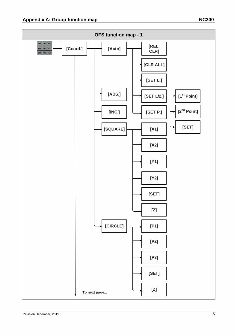
Appendix A: Group function map NC300
Revision December, 2015 5
OFS function map - 1
[Coord.] [Auto][REL. CLR]
[SET L/2.]
[SET L.]
[CLR ALL]
[SQUARE]
[ABS.]
[INC.]
[Z]
[X1]
[X2]
[Y1]
[Y2]
[SET]
[CIRCLE]
[Z]
[P1]
[P2]
[P3]
[SET]
[SET P.]
To next page...
[2nd Point]
[1st Point]
[SET]

NC300 Appendix A: Group function map
6 Revision December, 2015
OFS function map - 2
[CUTTER] [ABS.]
[INC.]
[SET H.]
[Clear] [H/D]
[Life]
[Wear]
[All]
[Maga 1][MAGA] [Set]
[RST All]
[UNLOCK]
[Set]
[RST All]
[UNLOCK]
[Global]
[Macro]
[Hold]
[Mage 2]
[Local]
[Expanded]
...from last page
[LOCK]
[LOCK]

Appendix A: Group function map NC300
Revision December, 2015 7
GRA function map 1
[Cutting path]
[X-Y/Y-Z/X-Z/X-Y-Z]
[Center]
[Zoom in]
[Zoom out]
[Draw]
[Stop drawing]
[Up]
[Down]
[Left]
[Right]
[X-Y/Y-Z/X-Z/X-Y-Z][Cutting preview]
[Center]
[Zoom in]
[Zoom out]
[Preview]
To next page...
[Stop preview]

NC300 Appendix A: Group function map
8 Revision December, 2015
GRA function map 2
ALM function map
[Alarm]
[History] [CLR All]

Appendix A: Group function map NC300
Revision December, 2015 9
DGN function map 1
[Machining] [Set NR.]
[CLR TIME]
[CLR NR.]
[User VAR.]
[User VAR.]
[Sys VAR.] [US DEC.]
[HEX.]
[S DEC.]
[FLOAT]
[X][Bit][MLC.]
[Y]
[M]
[A]
[T]
[C]
[T][REG]
[C(16)]
[C(32)]
[D]To next page... To next page...
[DEL]
[M VAR.]
[US DEC.]
[HEX.]
[S DEC.]
[FLOAT]
[DEL]

NC300 Appendix A: Group function map
10 Revision December, 2015
DGN function map 2

Appendix A: Group function map NC300
Revision December, 2015 11
DGN function map - 3
[ | ]
[DEL V-LN]
[ADD LN]
[DEL LN]
[DEL]
[LEBEL]
[TABLE]
[SYMBOL] [X]
[Y]
[M]
[A]
[T]
[C]
[D]
[P]
[I]
[DEL]
[COPY]
[PASTE]
...from last
page
...from last
page
...from last page
To next page...
To next page...
To next page...

NC300 Appendix A: Group function map
12 Revision December, 2015
DGN function map - 4
To next page...
To next page...
[SAVE]
[IMPORT]
[EXPORT]
[IMPORT]
[EXPORT]
[NEW FILE][JUMP TO]
[SELECT][VAR MONI]
[COPY]
[PASTE]
[ON][SET]
[OFF]
[RUN/STOP]
[JUMP TO]
[CUT]
[SYS MONI]
[SYS VAR]
[CH VAR]
[AXIS VAR]
[IF VAR]
[MLC VAR]
...from last page ...from last page ...from last page
[SRV MONI]
[I/O MONI]
[US DEC]

Appendix A: Group function map NC300
Revision December, 2015 13
DGN function map - 5
[STATUS] [BIT]
[HEX]
[S DEC]
[SYSTEM]
[FW SN]
[HW SN]
[S SCP][PWD] [UNLOCK]
[LOCK]
[PWD CHG]
[M SCP]
[LOCK/UNLOCK]
[RST U1]
[RST U2]
[PWD CHG]
[U1 SCP]
[LOCK/UNLOCK]
[PWD CHG]
[U2 SCP]
[LOCK/UNLOCK]
...from last page
To next page... To next page...
...from last page
[M STATUS]
[DEL]
[SYS CHECK]
[ENALBE] [OK]
[CANCEL ALL]
[DEFAULT]
[RESET]

NC300 Appendix A: Group function map
14 Revision December, 2015
DGN function map - 6
[TUNING]
[EXPIRE] [SETTING]
[RELEASE]
[EXP SCP][PWD CHG]
[LOCK/UNLOCK]
[NEX AX]
[READ]
[COMPUTE]
[WR GAIN]
[WR NOTH]
[RUN]
[JOG←]
[JOG→]
[POS 1]
[POS 2]
[TAP RIV]
[SERVO]
[TAP SET]
To next page...
...from last page ...from last page
[READ SRV]
[SYN CONTROL]
[POS SET]

Appendix A: Group function map NC300
Revision December, 2015 15
DGN function map - 7
[TEXT WR]
[IMPORT]
[EXPORT]
[LOGO WR]
[IMPORT]
[EXPORT]
...from last page
[SEL ALL]
[CRL ALL]
[SEL ALL]
[CRL ALL]

NC300 Appendix A: Group function map
16 Revision December, 2015
PAR function map - 1

Appendix A: Group function map NC300
Revision December, 2015 17
PAR function map - 2
[MLC] [Default]
[Color]
[Graphic] [Default]
[Color]
[Servo] [Read]
[CONFIG] [OK]
[Set RIO] [OK]
[PAR GROUP]
...from last page
[SERACH]
[SAVE]
[DEL GROUP]
[WRT PAR]
[READ PAR]
[PAR SEQ]
[ALLOCATE]

NC300 Appendix A: Group function map
18 Revision December, 2015
(This page is intentionally left blank.)