operating instructions for drilling and tapping machinethe a-3 drilling and tapping machine drills...
TRANSCRIPT

MAIN OFFICE and PLANT
500 West Eldorado Street
Decatur, Illinois 62522
www.muellercompany.com
A-3™ DRILLING AND TAPPINGMACHINE
Operating
Instructions for
DEPENDABLE S INCE 1857

MAIN OFFICE and PLANT
500 West Eldorado Street
Decatur, Illinois 62522
www.muellercompany.com
Copyright 1979 - MUELLER Co. Form 8941 - Rev. 7/06 - 500-1 Printed in U.S.A.
1. Read and follow instructions carefully. Proper training and periodic review regarding the use of this equipment is essential to prevent possible serious injuryand/or property damage. The instructions contained herein were developed for using this equipment on fittings of Mueller manufacturer only, and may not beapplicable for any other use.
2. Do not exceed the pressure ratings of any components or equipment. Exceeding the rated pressure may result in serious injury and/or property damage.3. Safety goggles and other appropriate protective gear should be used. Failure to do so could result in serious injury.4. Pressure test, check for and repair leaks in all fittings and components each time one is installed or any joint or connection is broken. Failure to find and
repair a leak from any source in the fittings, by-pass lines or equipment could result in an explosion and subsequent serious injury and/or property damage.5. MUELLER® Drilling Machines and Equipment have been carefully designed and engineered to work together as a unit. The use of equipment manufactured
by someone other than MUELLER Co. may cause excessive wear or a malfunction of the MUELLER machines.
All warranties, expressed or implied, for MUELLER Drilling Machines are rendered null and void if the machines are used with shell cutters orequipment manufactured by someone other than MUELLER Co.
! WARNING
A-3™ DRILLING AND TAPPINGMACHINE
Operating
Instructions for

Page
Maintenance
Instructions ...........................................................3
General Specifications ...........................................4
Instructions for Installing
and Operating A-3 Drilling
and Tapping Machine ......................................5-11
Parts for A-3 Drilling
and Tapping Machine .........................................12
2
www.muellercompany.com
INDEXA-3™ Drilling and
Tapping Machine

3
BEFORE USEClean and lubricate all wearing and bearing surfaces,particularly the boring bar, the boring bar collar, thecap sleeve threads, and the chain hook threads.
Inspect and clean all tools, particularly the shank ends,and remove any burrs or scale, which would preventproper alignment with the boring bar.
Inspect and clean the socket in the end of the boringbar and remove any burrs or scale which wouldprevent the tool from seating properly.
AFTER USEThoroughly clean the entire machine and all tools, andlubricate all machined surfaces.
Remove all chips from inside the body including theflop valve recess. A special body-cleaning chisel isfurnished for this purpose. If chips are permitted toaccumulate in the machine they could rust andbecome caked and interfere with the operation of theflop valve.
Flat link chain must be well lubricated and kept freefrom rust and dirt. It may be advisable to store flat linkchain in a container of oil when not in use.
The machine and all tools and equipment should bestored in the machine box. Carefully place tools in theirindividual compartments to prevent damage to thecutting edges.
BYPASS VALVE – Figure 1
Clean the bypass valve frequently.
Remove the hand knob screw, hand knob, seat nut,eat nut washer, and stem.
Clean out the valve ports and passages with a piece ofwire. A Bypass Clean Out Tap is available (part500529) which effectively cleans chips or foreignmaterial from the threaded area of the bypass valve.
If necessary, replace the seat washer and seat nutwasher with new MUELLER washers only. Ordinarywashers will not work satisfactorily.
IMPORTANT: Clean the recess below the stemthreads and the bottom inside stem thread inthe body. Chips may lodge at this location andprevent complete closure of the bypass valve.
FIGURE 1
By-Pass Valve Open By-Pass Valve Closed
A-3™ DRILLING & TAPPING MACHINEMaintenance Instructions

CAPACITY AND USE:The A-3 Machine is designed for hand or poweroperation and tools are fed automatically during thepower drilling operation.
A special mechanism permits the boring bar to belocked to the feed nut and yoke to prevent the drillfrom spiraling into the hole before the hole iscompletely drilled. It also prevents the drill fromdropping to the threaded section of the combined drilland tap. This design eliminates unnecessary tooldamage and is recommended for low-pressure drillings.
The A-3 Drilling and Tapping Machine drills and taps amain and inserts a valve, tee, or plug into the tappedhole in the main under pressure. The following itemscan be inserted with the A-3 machine.
*MUELLER GAS DISTRIBUTION PRODUCTS CATALOG lists the catalog numbers of the tees which can beinserted. A MUELLER Drilling Machine and itsequipment must also be used when inserting a NO-BLO® Service Tee. See instruction ”L” page 11.
Tools and saddles are offered for use with cast iron,ductile iron, cement-lined ductile iron, ductile ironO.D. PVC, A-C, and steel pipe in sizes from 6” to 48”.
MAXIMUM WORKING PRESSURE:90 psi without power clevis 200 psi with power clevis
RECOMMENDED MINIMUM SIZE OF CAST IRONMAIN FOR EACH SIZE OF TAPPING FORSERVICE CONNECTION
4
CUTTING GREASE
LARGE SADDLE GASKET
SMALL SADDLE GASKET
A-3 TAPPING MACHINE
A-3™ DRILLING & TAPPING MACHINEGeneral Specifications
A-3 MACHINE AND EQUIPMENT FURNISHEDShipped in Strong Wooden Box Total Shipping Weight: 188 Pounds
EQUIPMENT FURNISHED WITH EACH MACHINE:Ratchet Handle Chain WashersSmall Saddle Gasket Chain WrenchLarge Saddle Gasket Allen WrenchFlat Link Chain and Body Cleaning ChiselEyebolt with Nut Cutting Grease
Chain Hook and Nut
Sizes
Corporation Valves 1/2” 3/4” 1” 11/4” 11/2” 2”NO-BLO® Service Tees* 3/4” 1” 11/4” 11/2” 2”NO-BLO®
Service Stop Tees* 1” 11/4”Pipe Plugs 1” 11/4” 11/2” 2” 21/2”
Size of Tapping 1” 11/4” 11/2” 2” 21/2”Smallest Size of Main 4” 6” 6” 8” 10”Approximate Numberof full Threads 41/4 41/2 4 4 4
CLEANING CHISEL
CHAIN WRENCH WRENCH
ALLEN WRENCH

9. Hang eyebolt and washer (with chain) over the other side of the chain yoke.
10. Bring the chain around under the pipe and connect it with the chain hook. Be sure the chain is not twisted. The flat link chain hook is attached to the chain between two of the chain link pins and always with the notch in the hook on the outside (the side away from the body of the machine). FIGURE 3
11. Tighten chain hook nuts hand tight.12. Slide the machine around the pipe to the
desired angle.13. Tighten the chain hook nuts evenly.
Hammer the chain around the pipe to remove any twist in the chain and continue tightening both chain hook nuts until the machine is solidly bearing against the pipe.IMPORTANT – DO NOT tighten the chain hook nuts after starting to drill as it will throw the machine out of alignment.Use Web Belt (part no. 88693) when tapping wrapped and coated steel pipe. This web belt does not damage the exterior covering of the pipe. A-3 Machine chain is for use on pipe up to 16” in size. Use the proper length and type of extension chain when topping pipe in larger sizes.
5
A-3™ DRILLING & TAPPING MACHINEInstructions for Installing and Operating A-3 Drilling & Tapping Machine
FIGURE 2
A. SELECT THE EQUIPMENT REQUIRED
The following equipment must be selected fromthe latest WATER or GAS DISTRIBUTIONPRODUCTS CATALOG.
1. Select the proper combined drill (or shell cutter) and tap according to:a. Size and type of inlet thread on valve,
tee, or plug to be inserted.b. Material from which the pipe to be
tapped is made.c. Size and class of pipe to be tapped.
2. Select the proper saddle according to the size and type of pipe to be tapped.
3. Select the proper inserting tool.a. For corporation valves according to the
size and type of outlet.b. For tees according to the size of the
out-side thread at the top of the tee .c. For plugs according to the size.
4. Select proper extracting tool.a. For corporation valves according to the
size and type of outlet.b. For tees according to the size of the
outside thread at the top of the tee. c. For plugs according to the size.
5. Select the items of special equipment which may be required because of special operating conditions.
B. ATTACH THE MACHINE TO THE PIPE
1. Thoroughly clean the pipe at the location for the tap; include an area greater than the large saddle gasket.
2. Place the large saddle gasket on top of the pipe even with the location for the tap, with the raised projection up away from the pipe.
3. Place the saddle on the large saddle gasket.4. Place the small saddle gasket in the recess in
the top of the saddle. FIGURE 25. Unscrew the brass feed cap (containing the
boring bar assembly) from the cylinder of themachine.
6. Place the body and cylinder of the machine on top of the small saddle gasket. Position the machine so that the work “TOP” cast on the body is up if the machine is to be operated in any position other than vertical.
7. Unscrew nuts on chain hook and eye bolt until they are flush with the end of the threaded section.
8. Hang chain hook and washer over one side of the chain yoke.
FIGURE 3

C. ATTACH TOOL TO BORING BAR
1. Slide drift pin in boring bar socket so that head end is exposed.
2. Insert the proper combined drill (or shell cutter) and tap into the socket of the boring bar. Align the keyway in the tool shank with the key inside the socket of the boring bar.NOTE: The point of the tool retaining screw purposely contacts the upper side of the countersunk hole in the tool to maintain pressure on the shank of the tool to help retain it tightly in the socket of the boring bar.
3. Strike tool on end with a block of hard woodto make it fit tightly in socket.
4. Tighten tool-retaining screw in boring bar.5. Thoroughly coat the tool with special
MUELLER Cutting Grease. FIGURE 4. DO NOT use cutting grease when drilling and tapping A-C pipe.
6. Retract boring bar to its rearmost position.
D. ASSEMBLE THE MACHINE
1. Open the flop valve as far as it will go by turning the hand wheel clockwise.
2. Screw feed cap and boring bar assembly onto the cylinder of the machine.
3. Push boring bar down by hand until the toolcontacts the main.
4. Adjust the feed nut and yoke on cap sleeve so that the yoke is engaged with the collar on the boring bar. Raise the pivot arm of locking mechanism on side of yoke so that it is positioned under the collar, then lock in place with operating screw.
5. Turn bypass valve hand knob counter-clockwise as far as possible. This is the bypass position for this valve.
Ea. DRILL AND TAP – HAND OPERATED METHOD
1. Adjust ratchet dog in handle so that the boring bar will rotate clockwise.
2. Drill the hole by operating the ratchet handleclockwise and turning the feed yoke clockwise a little at a time. Use a light even feed at the start. If possible, pull the ratchet handle in an arc parallel to the axis of the pipe thereby reducing the tendency of the machine to slip on the pipe. FIGURE 5
3. Continue the drilling operation until the boring bar feeds easily and rotates easily, indicating the drill is through the pipe.
6
A-3™ DRILLING & TAPPING MACHINEInstructions for Installing and Operating A-3 Drilling & Tapping Machine
4. Rotate the feed yoke clockwise without rotating the boring bar until the tap part of the tool contacts the pipe.
5. Apply a downward pressure with the feed yoke and at the same time rotate the boring bar clockwise until the tap takes hold after which the feed yoke may be dropped off and the tool allowed to feed itself. NOTE: The feed yoke should remain in contact with the boring bar collar and should follow the feed of the tool when tapping under high pressure or when tapping thin wall or asbestos-cement pipe. DO NOToverfeed faster than the tool is cutting as this will strips the threads in the pipe.
FIGURE 4
FIGURE 5

7
6. Continue the tapping operation until the tapping line on the boring bar, just under the collar, is flush with the top thread on the feed cap sleeve. When tapping asbestos-cement pipe, it may be advisable to tap 1/8” beyond the line. FIGURE 6
Eb. DRILL AND TAP – POWER OPERATED METHOD USING MUELLER H-603 ELECTRIC POWER OPERATOR OR H-604 AIR POWER OPERATOR
The A-3 Drilling and Tapping Machine has beendesigned to permit the use of a power operator.The power operator will drive the combined drill(or shell cutter) and tap and provide automatic feedduring the drilling operation.
IMPORTANT: When using H-604 air motorpower operator install an in-line lubricator asclose to the unit as practical and adjust forslight oil mist from exhaust – maintainpressure of 90 p.s.i.g. We recommend theuse of a gage at the throttle to determine theactual pressure of AIR AT THE AIR MOTOR.
A-3™ DRILLING & TAPPING MACHINEInstructions for Installing and Operating A-3 Drilling & Tapping Machine
FIGURE 6 NOTE: Either unit is suitable for: • Power drilling with automatic feed 1/2” through1-1/4” inclusive with combined drill and tap.• Power cutting with automatic feed 1-1/4”through 2-1/2” inclusive with shell cutter and tap. • Power tapping by hand feed.
The gear case attaches to the machine by themeans of two sockets. The inner or small socketdrives the boring bar. The outer or large socketdrives the feed yoke through a gear reductionas the boring bar is rotated. The resulting feed onthe drill is .010” per revolution of the boring bar.The motors are equipped with a squeeze typetrigger throttle. If for some reason a drill shouldstick, the motor can be shut of quickly.
1. Place the gear case and motor on the drilling and tapping machine aligning the sockets with the square shanks on the boring bar and feed yoke. Socket which contacts feed yoke should be closed and wing nut tightened securely.
2. Set position of air or electric motor switch to give clockwise rotation of boring bar.
3. Start drilling operation and continue drilling until the operation is completed. Completion of drilling operation can be easily detected by torque required to resist power unit and sound of power unitNOTE: The tapping line is located just below the thrust collar on the boring bar. A distance of 11/4” below the tapping line is limit for use of automatic feed. Actual drilling is always completed before this distance is reached.
4. Loosen wing nut on feed yoke drive socket and swing socket open.
5. Start motor and rotate feed yoke clockwiseby hand to engage tap part of tool into main. Continue to rotate feed yoke until tap is securely started into the main. At this point, turn operating screw on locking mechanism counter-clockwise to unlock the pivot arm and remove the feed yoke from contact with the thrust collar. The boring bar will move downward allowing the tool to feed itself. NOTE: Feed yoke should remain in contact with the boring bar thrust collar and follow the thrust collar down when machine is being used on high pressure mains, thin wall steel pipe or asbestos-cement pipe. DO NOT overfeed faster than the tap is cutting as this will strip the threads being tapped in the main.
TAPPINGLINE

A-3™ DRILLING & TAPPING MACHINEInstructions for Installing and Operating A-3 Drilling & Tapping Machine
8
6. Continue tapping operation until tapping lineon boring bar is flush with the top of the feed sleeve part of the cap. Use 50 to 80 foot pounds of torque to tighten valve into main after removal of machine.
IMPORTANT – WHEN TAPPING A/C PIPE:Only hand operation of the A-3 machine isrecommended when working on A/C pipe,especially if it is not under pressure. If apower operator is used, its extra weight onthe boring bar can cause overfeeding of thetap and result in striped threads. Whentapping A/C pipe with one-piece CEM-RES®
Combined Drills and Taps, it is advisable toexceed the tapping line enough to allowcorporation valves to be inserted with onlyone to three threads exposed. The exactamount may be determined by making a“shop tap” ahead of time.
F. REMOVE THE TOOL
1. If hand ratchet was used, reverse the ratchet handle by pulling outward on ratchet detent knob and adjusting it for counter-clockwiserotation. Rotate the ratchet handle counter-clockwise carefully and back out the tool. Do not force the tool when removing it, as this may cause breakage of the tap teeth.CAUTION: When this machine is underpressure, water pressure from the mainwill create a piston action against theboring bar and it will tend to rise force-fully. Keep head and body clear of ratchethandle and end of boring bar. To avoidpossible bodily injury or damage to themachine that could result if the boringbar is allowed to move upward withoutconstraint, MAINTAIN CONTROL OF THEBORING BAR AT ALL TIMES with firmdownward force on the ratchet handle orpower operator.
2. If power operation has been used to make the tap, stop power operator momentarily, then reverse the motor and back out the tool. Control upward movement of the boring bar by maintaining a firm hold on the gear case and motor as stated in previous caution note.
3. When the tap is entirely free from the pipe, withdraw the boring bar to the uppermost position again applying some downward force to prevent uncontrolled withdrawal of the boring bar. When the pressure in the pipe is greater than 90 p.s.i., use the power clevis to control the withdrawal of the boringbar. FIGURE 7a. Hook the bent end of the power clevis
over the feed cap handles.b. Adjust the screw so that the point on the
end is in the center hole in the end of theboring bar.
c. Turn the screw to move the boring bar asrequired.
4. With the tool completely in the cylinder close flop valve by turning hand wheel as far as it will go counter-clockwise and hold momentarily.
5. With the other hand quickly close the bypassvalve by turning the hand knob clockwise.This relieves the pressure in the cylinder and holds the flop valve closed.
6. Unscrew the feed cap and boring bar assembly.
FIGURE 7
9
A-3™ DRILLING & TAPPING MACHINEInstructions for Installing and Operating A-3 Drilling & Tapping Machine
FIGURE 8
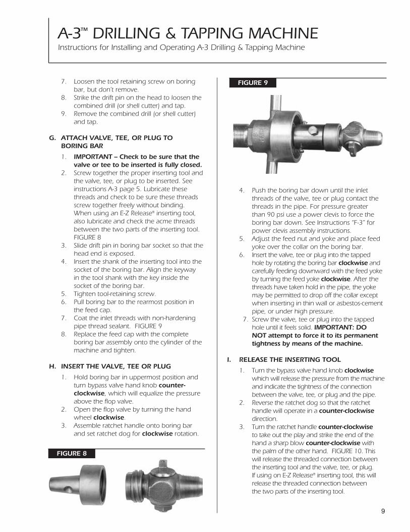
FIGURE 97. Loosen the tool retaining screw on boring bar, but don’t remove.
8. Strike the drift pin on the head to loosen the combined drill (or shell cutter) and tap.
9. Remove the combined drill (or shell cutter) and tap.
G. ATTACH VALVE, TEE, OR PLUG TO BORING BAR
1. IMPORTANT – Check to be sure that the valve or tee to be inserted is fully closed.
2. Screw together the proper inserting tool andthe valve, tee, or plug to be inserted. See instructions A-3 page 5. Lubricate these threads and check to be sure these threads screw together freely without binding. When using an E-Z Release® inserting tool, also lubricate and check the acme threads between the two parts of the inserting tool. FIGURE 8
3. Slide drift pin in boring bar socket so that thehead end is exposed.
4. Insert the shank of the inserting tool into the socket of the boring bar. Align the keyway in the tool shank with the key inside the socket of the boring bar.
5. Tighten tool-retaining screw. 6. Pull boring bar to the rearmost position in
the feed cap.7. Coat the inlet threads with non-hardening
pipe thread sealant. FIGURE 98. Replace the feed cap with the complete
boring bar assembly onto the cylinder of the machine and tighten.
H. INSERT THE VALVE, TEE OR PLUG
1. Hold boring bar in uppermost position and turn bypass valve hand knob counter-clockwise, which will equalize the pressure above the flop valve.
2. Open the flop valve by turning the hand wheel clockwise.
3. Assemble ratchet handle onto boring bar and set ratchet dog for clockwise rotation.
4. Push the boring bar down until the inletthreads of the valve, tee or plug contact the threads in the pipe. For pressure greater than 90 psi use a power clevis to force the boring bar down. See Instructions “F-3” for power clevis assembly instructions.
5. Adjust the feed nut and yoke and place feed yoke over the collar on the boring bar.
6. Insert the valve, tee or plug into the tapped hole by rotating the boring bar clockwise and carefully feeding downward with the feed yokeby turning the feed yoke clockwise. After the threads have taken hold in the pipe, the yoke may be permitted to drop off the collar except when inserting in thin wall or asbestos-cement pipe, or under high pressure.
7. Screw the valve, tee or plug into the tapped hole until it feels solid. IMPORTANT: DO NOT attempt to force it to its permanent tightness by means of the machine.
I. RELEASE THE INSERTING TOOL
1. Turn the bypass valve hand knob clockwisewhich will release the pressure from the machine and indicate the tightness of the connection between the valve, tee, or plug and the pipe.
2. Reverse the ratchet dog so that the ratchet handle will operate in a counter-clockwisedirection.
3. Turn the ratchet handle counter-clockwiseto take out the play and strike the end of the hand a sharp blow counter-clockwise with the palm of the other hand. FIGURE 10. This will release the threaded connection between the inserting tool and the valve, tee, or plug. If using on E-Z Release® inserting tool, this will release the threaded connection between the two parts of the inserting tool.

A-3™ DRILLING & TAPPING MACHINEInstructions for Installing and Operating A-3 Drilling & Tapping Machine
10
FIGURE 10
FIGURE 11
4. Rotate ratchet handle counter-clockwiseuntil inserting tool is completely free.NOTE: If there is full pressure flow from the bypass release valve, the inserting tool has not released and the valve, tee or plug should be screwed in again a little tighter than before and another attempt be made to release the inserting tool.
J. REMOVE THE MACHINE
1. Loosen the chain nuts.2. Unhook the chain.3. Remove the machine, saddle and gaskets. 4. Tighten the valve, tee or plug into the pipe
permanently with a flat wrench on the valve body. Figure 11.
5. If using an E-Z Release® inserting tool, remove the nut part from the valve or tee.
K. TO REMOVE A VALVE, TEE OR PLUG INSTALLED IN A PIPE UNDER PRESSURE
1. Shut off the valve or tee.2. Disconnect service line piping.3. Slightly loosen the valve or tee using a
wrench on the inlet side.4. Separate the two parts of the extracting tool.5. When using an extracting tool having inside
threads, screw the nut onto the outside threads of valve or tee very securely using the right hand thread. Figure 12. When using an extracting tool having outside threads, screw the plug into the inside threads of valve or plug very securely using the right hand threads.
6. Unscrew the feed cap containing the boring bar assembly from the cylinder on the machine.
7. Open the flop valve by turning the hand wheel clockwise.
8. Assemble the large saddle gasket, saddle, small saddle gasket and the body and cylinder of the machine centrally over the installed valve, tee or plug. Chain hook nuts should be only hand tight. See instructions “B”, page 5.
9. Insert the shank part of the extracting tool into the socket of the boring bar. Align the keyway in the tool shank with the key inside the socket of the boring bar. Figure 12.
10. Tighten tool-retaining screw.11. Pull boring bar to the rearmost position in
the feed cap.
FIGURE 12

A-3™ DRILLING & TAPPING MACHINEInstructions for Installing and Operating A-3 Drilling & Tapping Machine
11
12. Replace the feed cap with the complete boring bar assembly onto the cylinder of the machine and tighten.
13. Turn bypass valve hand knob counter-clockwise.
14. Push the boring bar down and engage the two parts of the extracting tool by rotating the boring bar counter-clockwise.
15. Carefully align the machine and tighten the chain nuts without binding the boring bar.
16. Again rotate the ratchet handle counter-clockwise which will first fully engage the two parts of the extracting tool and continued rotation will unscrew the valve, tee or plug from the pipe.
17. Slowly raise boring bar, close flop valve by turning the hand wheel counter-clockwise,and close the bypass valve by turning the hand knob clockwise.
18. Proceed with the use of the machine following previous instructions.
CAUTION: Once the valve, tee or plug threadsseparate from the pipe and the machine isunder pressure, water pressure from the mainwill create a piston action against the boringbar and it will tend to rise forcefully. Keephead and body clear of ratchet handle andend of boring bar. To avoid possible bodilyinjury or damage to the machine that couldresult if the boring bar is allowed to moveupward without constraint, MAINTAIN CON-TROL OF THE BORING BAR AT ALL TIMES withfirm downward force on the ratchet handle.
L. INSTALLING MUELLER® NO-BLO®
SERVICE TEES
A NO-BLO® Service Tee having outside I. P. threadinlet may be installed with the A-3 Machine and adrilling machine (or completion machine) and itsequipment. MUELLER GAS DISTRIBUTIONPRODUCTS CATALOG lists the catalog numbers ofthe tees which can be installed with the A-3Machine.
1. Refer to the current Gas Distribution ProductsCatalog. Determine the catalog number of the drilling machine (or completion machine)the control valve and tools to be used.
2. Select the proper size of control valve or control chamber bushing. This is listed in the CATALOG with the control valve or control chamber.
3. Screw the deferred completion stopper into the tee making a pressure tight shut-off. Figure 13.
4. Insert the tee (with deferred completion stopper assembled) by following instructions. “G”, “H”, “I”, and “J” starting on page 9.
5. Connect service pipe to the outlet of the tee and extend this piping to the first shut-off in the service line such as a curb valve or meter valve. Close this curb valve or meter valve.
For the following operations, refer to OPERATINGINSTRUCTIONS FOR INSTALLING NO-BLO® SERVICETEES WITH THE DRILLING MACHINE SELECTEDFOR THIS USE.6. Remove the deferred completion stopper.
Follow the instructions for removing completion plug from Service Tees.
7. Insert completion plug.8. Apply non-hardening pipe thread sealant to
completion cap threads and screw tightly on tee. FIGURE 14.
9. Test the entire tee with soapsuds (add glycerine in freezing weather) or leak detection fluid.
FIGURE 13
FIGURE 14

A-3™ DRILLING & TAPPING MACHINEParts
12
RATCHET HANDLE 83508
A-3 TAPPING MACHINECOMPLETE MODEL NO. 1
ROLL PIN 502027
PIVOT ARM SPRING 502026
PIVOT ARM 502025
OPERATING SCREW502028LOCK NUT
502029
2-BORING BAR O-RINGS 51458
SET SCREW 98430
2-HANDLES 40020
FEED SLEEVE O-RING 45374
CAP 503148
CAP GASKET40189
YOKE RETAINING PIN 40023
OIL PLUG41435
FEED SLEEVE503149
FEED YOKE
580898
HANDLE EXTENSION86391
HANDLE BAR40177
RATCHET WHEEL40137
STUD40139
RATCHET DOG40004
SPRING40007
SPRING PIN40006
CUTTING GREASE88366
HAND WHEEL NUT 58849
GATE SCREWWASHER 40203
VALVE STEM40194
STEM SETSCREW40013
GATEWASHER40197
SEATWASHER40198
GATE 40196
GATE ARM40195
STEW PACKINGNUT 40193
STEW PACKINGWASHER 58461
LOCK NUT60040
CHAIN 6”-16” MAIN85318
2-CHAIN HOOKWASHERS 40212
CHAIN HOOK89099
LARGE SADDLE GASKET40230
CLEANING CHISEL40205
SPANNER WRENCH60041
CHAIN WRENCH40028
WRENCH 75409
SMALL SADDLE GASKET
40229
CHAIN NUT40211
RETAINING PIN56694
BORING BAR503150
FRICTION COLLAR580610
2-RETAINING SCREWS
79745
2-WASHERS50133
BORING BAR NUT 51479
2-DETENTSCREWS305006 2-DETENT
SPRINGS 59810
2-DETENTS500851
FRICTION COLLAR ROLLPIN 48130
DRIFT PIN 40015
TOOL RETAININGSCREW62501
STUFFING NUT58094PACKING
58101
CYLINDER58093
CHAIN YOKE40213
HAND KNOB 40043SEAT NUT 40048
SEAT NUT WASHER 40049STEM 40045
SEAT WASHER 42042SCREW 40047
GATE TO ARM SCREW 40202
SEAT WASHER SCREW 40200
STEW HAND WHEEL 58519
NUT47503
BOLT40138
HAND KNOBSCREW 40044
