drilling and 1.1 tapping machines - royal...
TRANSCRIPT
1.1MUELLER® DRILLING ANDTAPPING MACHINES
Drilling and tapping machine selection guideMachine Description Corporation
stop capacityPipe plugcapacity
Maximumpressure
Operation Recommended uses
B-101
Tapping machine
1/2" - 1" 1/2" - 2-1/2"90 psig (621 kPa)250 psig(1724kPa)*
Hand or powerDrilling and tapping pressurized mainsand inserting corporation stops or pipeplugs without loss of water.
A-3 1" - 2" 1" - 2-1/2"90 psig (621 kPa)200 psig (1379 kPa)*
“J” 1/2" - 2" 1/4" - 2" Dry or open mains only Hand Drilling and tapping dry or open mains.
In 1871, Hieronymus Mueller, founder of the MUELLER Co., invented and patented the first machine for drilling, tapping and inserting corporation stops in mains under pressure.
This invention revolutionized the method of making main to service connections under pressure and also established what has proven to be the most successful principle for machines of this type. This
has been proven by the fact that MUELLER ma-chines are the accepted standard by most water com-panies, plumbers, and plumbing contractors. MUELLER Co. has taken the original tapping ma-chine features and refined, expanded andincorporated them into additional machines for other conditions and purposes. MUELLER Co. offers the most complete line of time proven drilling and tap-ping machines available.
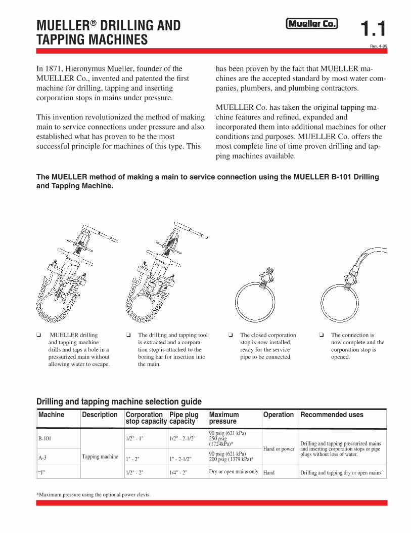
The MUELLER method of making a main to service connection using the MUELLER B-101 Drilling and Tapping Machine.
o MUELLER drilling and tapping machine drills and taps a hole in a pressurized main without allowing water to escape.
o The drilling and tapping tool is extracted and a corpora-tion stop is attached to the boring bar for insertion into the main.
o The closed corporation stop is now installed, ready for the service pipe to be connected.
o The connection is now complete and the corporation stop is opened.
Rev. 4-99
*Maximum pressure using the optional power clevis.
1.2Rev. 8-04 Shaded area indicates change
MUELLER® DRILLINGAND TAPPING MACHINES
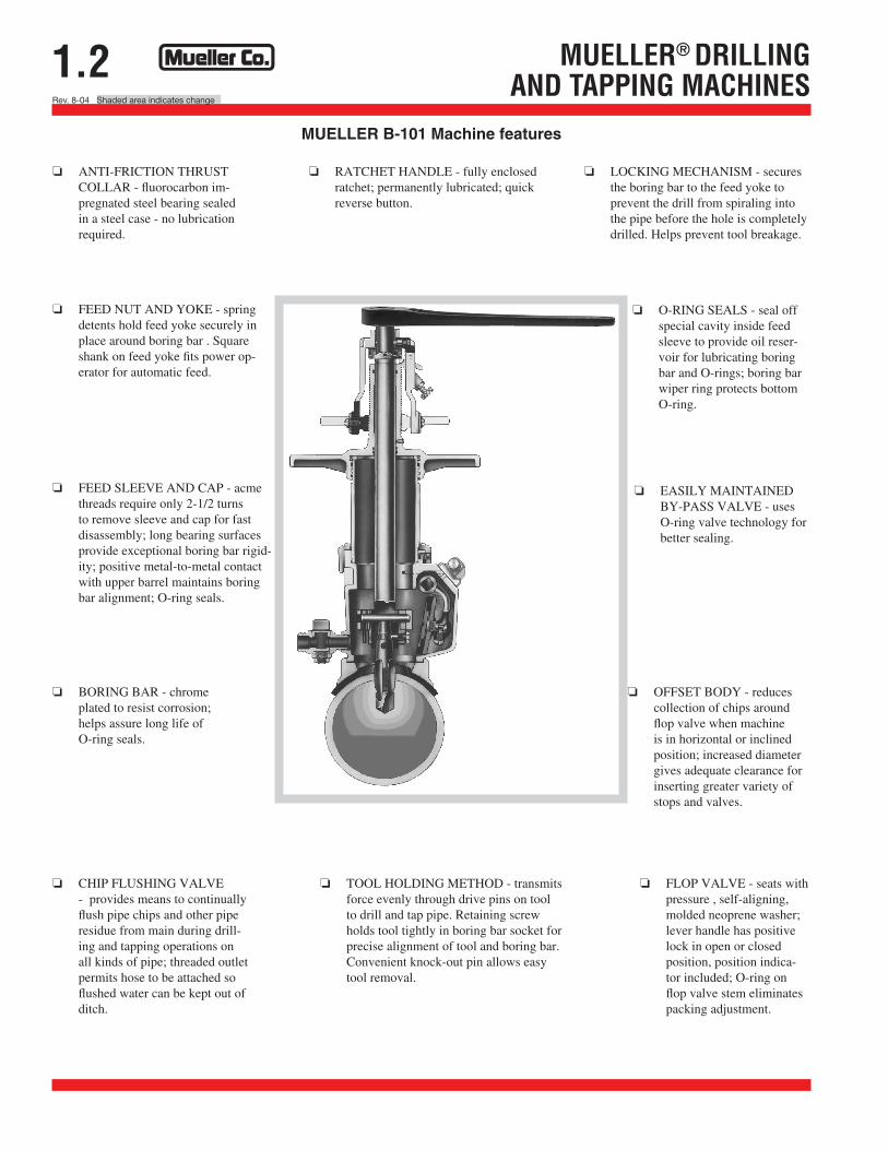
MUELLER B-101 Machine features
o ANTI-FRICTION THRUST COLLAR - fluorocarbon im-pregnated steel bearing sealed in a steel case - no lubrication required.
o RATCHET HANDLE - fully enclosed ratchet; permanently lubricated; quick reverse button.
o LOCKING MECHANISM - secures the boring bar to the feed yoke to prevent the drill from spiraling into the pipe before the hole is completely drilled. Helps prevent tool breakage.
o FEED NUT AND YOKE - spring detents hold feed yoke securely in place around boring bar . Square shank on feed yoke fits power op-erator for automatic feed.
o FEED SLEEVE AND CAP - acme threads require only 2-1/2 turns to remove sleeve and cap for fast disassembly; long bearing surfaces provide exceptional boring bar rigid-ity; positive metal-to-metal contact with upper barrel maintains boring bar alignment; O-ring seals.
o O-RING SEALS - seal off special cavity inside feed sleeve to provide oil reser-voir for lubricating boring bar and O-rings; boring bar wiper ring protects bottom O-ring.
o BORING BAR - chrome plated to resist corrosion; helps assure long life of O-ring seals.
o EASILY MAINTAINED BY-PASS VALVE - uses O-ring valve technology for better sealing.
o OFFSET BODY - reduces collection of chips around flop valve when machine is in horizontal or inclined position; increased diameter gives adequate clearance for inserting greater variety of stops and valves.
o CHIP FLUSHING VALVE - provides means to continually flush pipe chips and other pipe residue from main during drill-ing and tapping operations on all kinds of pipe; threaded outlet permits hose to be attached so flushed water can be kept out of ditch.
o TOOL HOLDING METHOD - transmits force evenly through drive pins on tool to drill and tap pipe. Retaining screw holds tool tightly in boring bar socket for precise alignment of tool and boring bar. Convenient knock-out pin allows easy tool removal.
o FLOP VALVE - seats with pressure , self-aligning, molded neoprene washer; lever handle has positive lock in open or closed position, position indica-tor included; O-ring on flop valve stem eliminates packing adjustment.

1.27Shaded area indicates change Rev. 8-04
ItemNo.
PartNumber
Part Name ItemNo.
PartNumber
Part Name ItemNo.
PartNumber
Part Name
1 83990 Cover sub assembly 20 501391 Body gasket 44 501401 Flat washer1-a 501383 Cover 21 305105 Cap screws-socket head-8 45 501397 Drive shaft nut1-b 501385 Drive shaft feed yoke bearing 22 40855 Feed yoke drive shaft seal 46 45374 O-ring1-c 501384 Pinion shaft cover bearing 23 302846 Drive shaft seal 47 501396 Cover cap2 83989 Body, sub assembly 24 501989 Coupler 48 301149 Cover cap screws-socket hd.-42-a 501380 Body 25 40849 Feed tube gear 49 89784 Drive shaft sub2-b 501986 Alignment pins —2 26 305539 Key 49-a 501387 Drive shaft bearing2-c 501381 Pinion shaft body bearing 27 501407 Driver arm—-left 49-b 505372 Drive shaft2-d 501382 Drive shaft bearing 28 501408 Driver arm—-right 50 502571 See note 13 83987 Drive shaft feed yoke assemb. 29 501393 Spring, driver arm 51 502572 Ing-R adapter handle4 40850 Pinion gear & shaft 30 501400 Hinge shaft 52 502573 Ing-R throttle valve body5 40852 Large shaft gear 31 501144 Hinge shaft pin (Rollpin) 53 505081 Motor mfg. screws — 46 98223 Woodruff key 32 500702 Stop pin (Rollpin) 54 505294 Throttle connector8 501402 Washer 33 501415 Eye bolt 55 501261 Spindle10 40851 Boring bar gear 34 501412 Eye bolt shaft (Rollpin) 56 505383 Vanes — 5 (not shown)*11 505373 Worm wheel 35 501394 Washer-wing nut 57 505384 Cylinder (not shown)12 501403 Worm 36 94341 Wing nut 58 506723 Backhead gasket13 501395 Spacers —2 37 92741 Motor clamp socket cap screw 59 507196 Motor housing14 501406 Worm shaft bearings —2 38 41435 Oil level plugs-allen-2 61 311322 Muffler15 501404 Worm shaft 39 97763 Plug-lock allen set screw 62 311321 Street elbow16 305537 Worm shaft key 40 307609 Motor holding cap screws-4 63 VSM-620 Air motor reversing lever17 501416 Worm shaft oil seal 41 505457 Name plate 64 311816 Constant feed oiler assembly18 501398 Thrust plug 42 90377 Cotter pin19 305535 Square key 43 301150 Motor handle cap screws-2
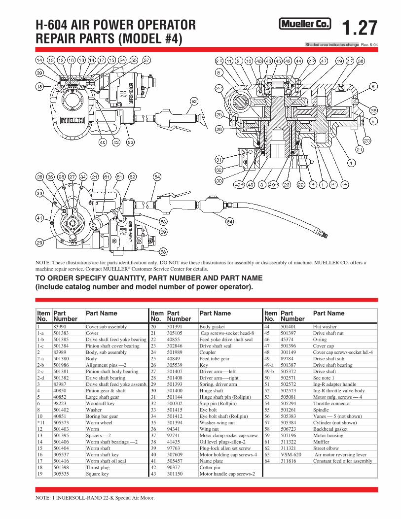
H-604 AIR POWER OPERATOR REPAIR PARTS (MODEL #4)
NOTE: These illustrations are for parts identification only. DO NOT use these illustrations for assembly or disassembly of machine. MUELLER CO. offers a machine repair service. Contact MUELLER® Customer Service Center for details.
TO ORDER SPECIFY QUANTITY, PART NUMBER AND PART NAME (include catalog number and model number of power operator).
NOTE: 1 INGERSOLL-RAND 22-K Special Air Motor.
1.26Rev. 8-04 Shaded area indicates change
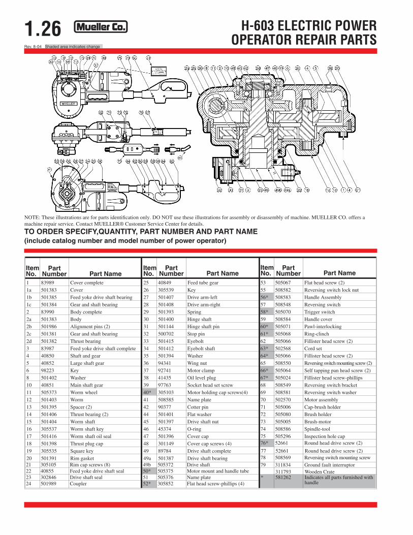
H-603 ELECTRIC POWER OPERATOR REPAIR PARTS
NOTE: These illustrations are for parts identification only. DO NOT use these illustrations for assembly or disassembly of machine. MUELLER CO. offers a machine repair service. Contact MUELLER® Customer Service Center for details.
TO ORDER SPECIFY,QUANTITY, PART NUMBER AND PART NAME (include catalog number and model number of power operator)
ItemNo.
PartNumber Part Name
ItemNo.
PartNumber Part Name
PartNumber Part Name
1 83989 Cover complete 25 40849 Feed tube gear 53 505067 Flat head screw (2)
1a 501383 Cover 26 305539 Key 55 508582 Reversing switch lock nut
1b 501385 Feed yoke drive shaft bearing 27 501407 Drive arm-left 56* 508583 Handle Assembly
1c 501384 Gear and shaft bearing 28 501408 Drive arm-right 57 508548 Reversing switch
2 83990 Body complete 29 501393 Spring 58* 505070 Trigger switch
2a 501383 Body 30 501400 Hinge shaft 59 508584 Handle cover
2b 501986 Alignment pins (2) 31 501144 Hinge shaft pin 60* 505071 Pawl-interlocking
2c 501381 Gear and shaft bearing 32 500702 Stop pin 61* 505068 Ring-clinch
2d 501382 Thrust bearing 33 501415 Eyebolt 62 505066 Fillister head screw (2)
3 83987 Feed yoke drive shaft complete 34 501412 Eyebolt shaft 63* 502568 Cord set
4 40850 Shaft and gear 35 501394 Washer 64* 505066 Fillister head screw (2)
5 40852 Large shaft gear 36 94341 Wing nut 65 508550 Reversing switch mounting screw (2)
6 98223 Key 37 92741 Motor clamp 66* 505064 Self tapping pan head screw (2)
8 501402 Washer 38 41435 Oil level plug 67* 505024 Fillister head screw-phillips
10 40851 Main shaft gear 39 97763 Socket head set screw 68 508549 Reversing switch bracket
11 505373 Worm wheel 40* 305103 Motor holding cap screws(4) 69 508581 Reversing switch washer
12 501403 Worm 41 508585 Name plate 70 502570 Motor assembly
13 501395 Spacer (2) 42 90377 Cotter pin 71 505006 Cap-brush holder
14 501406 Thrust bearing (2) 44 501401 Flat washer 72 505080 Brush holder
15 501404 Worm shaft 45 501397 Drive shaft nut 73 505005 Brush-motor
16 305537 Worm shaft key 46 45374 O-ring 74 508586 Spindle-tool
17 501416 Worm shaft oil seal 47 501396 Cover cap 75 505296 Inspection hole cap
18 501398 Thrust plug cap 48 301149 Cover cap screws (4) 76* 52661 Round head drive screw (2)
19 305535 Square key 49 89784 Drive shaft complete78 508569 Reversing switch mounting screw20 501391 Rim gasket 49a 501387 Drive shaft bearing79 311834 Ground fault interruptor
ItemNo.
21 305105 Rim cap screws (8) 49b 505372 Drive shaft22 40855 Feed yoke drive shaft seal 50* 505375 Motor mount and handle tube23 302846 Drive shaft seal 51 505376 Name plate24 501989 Coupler 52* 305852 Flat head screw-phillips (4)
311793 Wooden Crate
77 52661 Round head drive screw (2)
* 581262 Indicates all parts furnished with handle
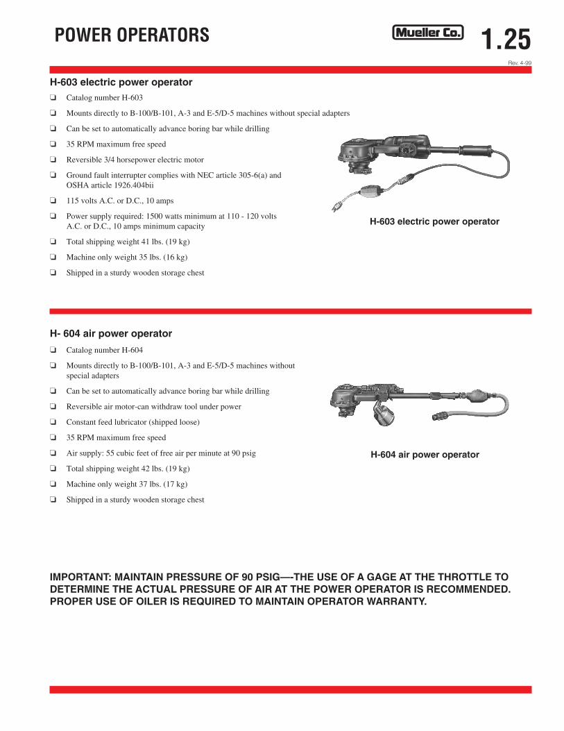
1.25 POWER OPERATORS
H-603 electric power operator o Catalog number H-603
o Mounts directly to B-100/B-101, A-3 and E-5/D-5 machines without special adapters
o Can be set to automatically advance boring bar while drilling
o 35 RPM maximum free speed
o Reversible 3/4 horsepower electric motor
o Ground fault interrupter complies with NEC article 305-6(a) andOSHA article 1926.404bii
o 115 volts A.C. or D.C., 10 amps
o Power supply required: 1500 watts minimum at 110 - 120 volts A.C. or D.C., 10 amps minimum capacity
o Total shipping weight 41 lbs. (19 kg)
o Machine only weight 35 lbs. (16 kg)
o Shipped in a sturdy wooden storage chest
H-603 electric power operator
H- 604 air power operator
o Catalog number H-604
o Mounts directly to B-100/B-101, A-3 and E-5/D-5 machines withoutspecial adapters
o Can be set to automatically advance boring bar while drilling
o Reversible air motor-can withdraw tool under power
o Constant feed lubricator (shipped loose)
o 35 RPM maximum free speed
o Air supply: 55 cubic feet of free air per minute at 90 psig
o Total shipping weight 42 lbs. (19 kg)
o Machine only weight 37 lbs. (17 kg)
o Shipped in a sturdy wooden storage chest
H-604 air power operator
IMPORTANT: MAINTAIN PRESSURE OF 90 PSIG—-THE USE OF A GAGE AT THE THROTTLE TO DETERMINE THE ACTUAL PRESSURE OF AIR AT THE POWER OPERATOR IS RECOMMENDED. PROPER USE OF OILER IS REQUIRED TO MAINTAIN OPERATOR WARRANTY.
Rev. 4-99
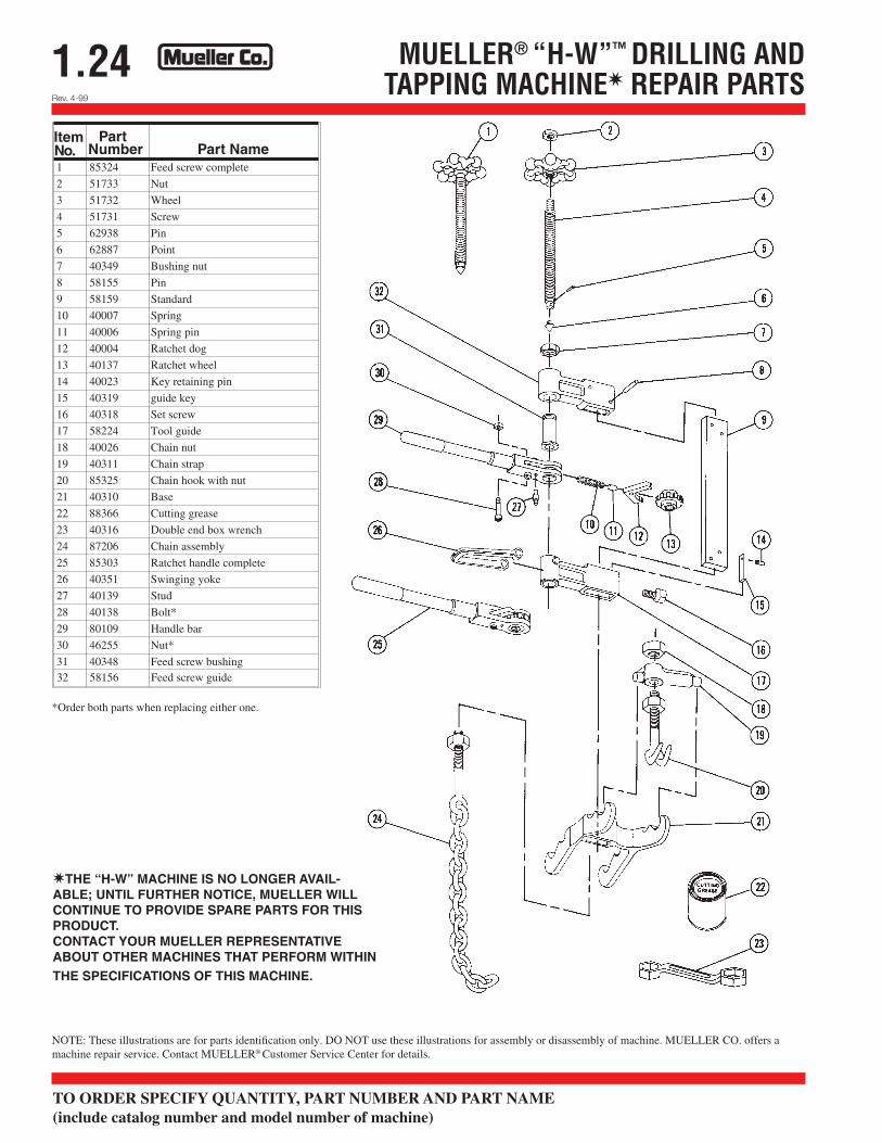
1.24 MUELLER® “H-W”™ DRILLING ANDTAPPING MACHINEW REPAIR PARTS
ItemNo.
PartNumber Part Name
1 85324 Feed screw complete
2 51733 Nut
3 51732 Wheel
4 51731 Screw
5 62938 Pin
6 62887 Point
7 40349 Bushing nut
8 58155 Pin
9 58159 Standard
10 40007 Spring
11 40006 Spring pin
12 40004 Ratchet dog
13 40137 Ratchet wheel
14 40023 Key retaining pin
15 40319 guide key
16 40318 Set screw
17 58224 Tool guide
18 40026 Chain nut
19 40311 Chain strap
20 85325 Chain hook with nut
21 40310 Base
22 88366 Cutting grease
23 40316 Double end box wrench
24 87206 Chain assembly
25 85303 Ratchet handle complete
26 40351 Swinging yoke
27 40139 Stud
28 40138 Bolt*
29 80109 Handle bar
30 46255 Nut*
31 40348 Feed screw bushing32 58156 Feed screw guide
*Order both parts when replacing either one.
WTHE “H-W” MACHINE IS NO LONGER AVAIL-ABLE; UNTIL FURTHER NOTICE, MUELLER WILL CONTINUE TO PROVIDE SPARE PARTS FOR THIS PRODUCT. CONTACT YOUR MUELLER REPRESENTATIVE ABOUT OTHER MACHINES THAT PERFORM WITHIN THE SPECIFICATIONS OF THIS MACHINE.
NOTE: These illustrations are for parts identification only. DO NOT use these illustrations for assembly or disassembly of machine. MUELLER CO. offers a machine repair service. Contact MUELLER® Customer Service Center for details.
TO ORDER SPECIFY QUANTITY, PART NUMBER AND PART NAME (include catalog number and model number of machine)
Rev. 4-99
Rev. 9-09
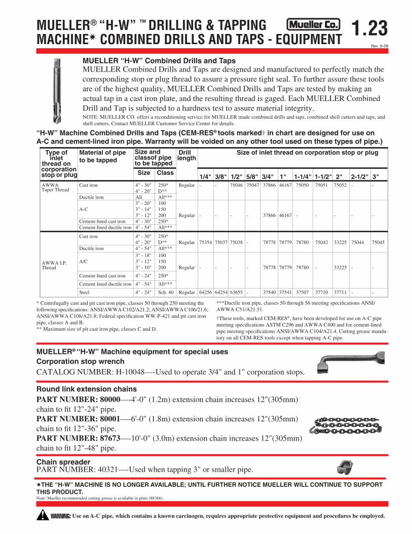
1.23MUELLER® “H-W” ™ DRILLING & TAPPING MACHINEWCOMBINED DRILLS AND TAPS - EQUIPMENT
Type ofinlet
thread oncorporationstop or plug
Material of pipeto be tapped
Size andclassof pipeto be tapped
Drilllength
Size of inlet thread on corporation stop or plug
Size Class1/4" 3/8" 1/2" 5/8" 3/4" 1" 1-1/4" 1-1/2" 2" 2-1/2" 3"
AWWATaper Thread
Cast iron 4" - 30" 250* Regular - - 75046 75047 37866 46167 75050 75051 75052 - -4" - 20" D**
Ductile iron All All***3" - 20" 100
A-C 3" - 14" 1503" - 12" 200 Regular - - - - 37866 46167 - - - - -
Cement-lined cast iron 4" - 30" 250*Cement-lined ductile iron 4" - 54" All***
Cast iron 4" - 30" 250*4" - 20" D** Regular 75354 75037 75038 - 78778 78779 78780 75042 33225 75044 75045
Ductile iron 4" - 54" All***3" - 18" 100
A/C 3" - 12" 1503" - 10" 200 Regular - - - - 78778 78779 78780 - 33225 - -
Cement-lined cast iron 4" - 24" 250*
Cement-lined ductile iron 4" - 54" All***
Steel 4" - 24" Sch. 40 Regular 64256 64254 63655 - 37540 37541 37507 37710 37711 - -
AWWA I.P.Thread
MUELLER “H-W” Combined Drills and Taps MUELLER Combined Drills and Taps are designed and manufactured to perfectly match the corresponding stop or plug thread to assure a pressure tight seal. To further assure these tools are of the highest quality, MUELLER Combined Drills and Taps are tested by making an actual tap in a cast iron plate, and the resulting thread is gaged. Each MUELLER Combined Drill and Tap is subjected to a hardness test to assure material integrity. NOTE: MUELLER CO. offers a reconditioning service for MUELLER made combined drills and taps, combined shell cutters and taps, and shell cutters. Contact MUELLER Customer Service Center for details.
“H-W” Machine Combined Drills and Taps (CEM-RES® tools marked† in chart are designed for use onA-C and cement-lined iron pipe. Warranty will be voided on any other tool used on these types of pipe.)
* Centrifugally cast and pit cast iron pipe, classes 50 through 250 meeting the following specifications: ANSI/AWWA C102/A21.2; ANSI/AWWA C106/21.6; ANSI/AWWA C108/A21.8; Federal specification WW-P-421 and pit cast iron pipe, classes A and B. ** Maximum size of pit cast iron pipe, classes C and D.
***Ductile iron pipe, classes 50 through 56 meeting specifications ANSI/AWWA C51/A21.51.
†These tools, marked CEM-RES®, have been developed for use on A-C pipe meeting specifications ASTM C296 and AWWA C400 and for cement-lined pipe meeting specifications ANSI/AWWA C104/A21.4. Cutting grease manda-tory on all CEM-RES tools except when tapping A-C pipe.
MUELLER® “H-W” Machine equipment for special uses Corporation stop wrench CATALOG NUMBER: H-10048—-Used to operate 3/4" and 1" corporation stops.
Round link extension chains PART NUMBER: 80000—-4'-0" (1.2m) extension chain increases 12"(305mm) chain to fit 12"-24" pipe. PART NUMBER: 80001—-6'-0" (1.8m) extension chain increases 12"(305mm) chain to fit 12"-36" pipe. PART NUMBER: 87673—-10'-0" (3.0m) extension chain increases 12"(305mm) chain to fit 12"-48" pipe.
Chain spreader PART NUMBER: 40321—-Used when tapping 3" or smaller pipe.
WTHE “H-W” MACHINE IS NO LONGER AVAILABLE; UNTIL FURTHER NOTICE MUELLER WILL CONTINUE TO SUPPORT THIS PRODUCT. Note: Mueller recommended cutting grease is available in pints (88366).
WARNING: Use on A-C pipe, which contains a known carcinogen, requires appropriate protective equipment and procedures be employed.
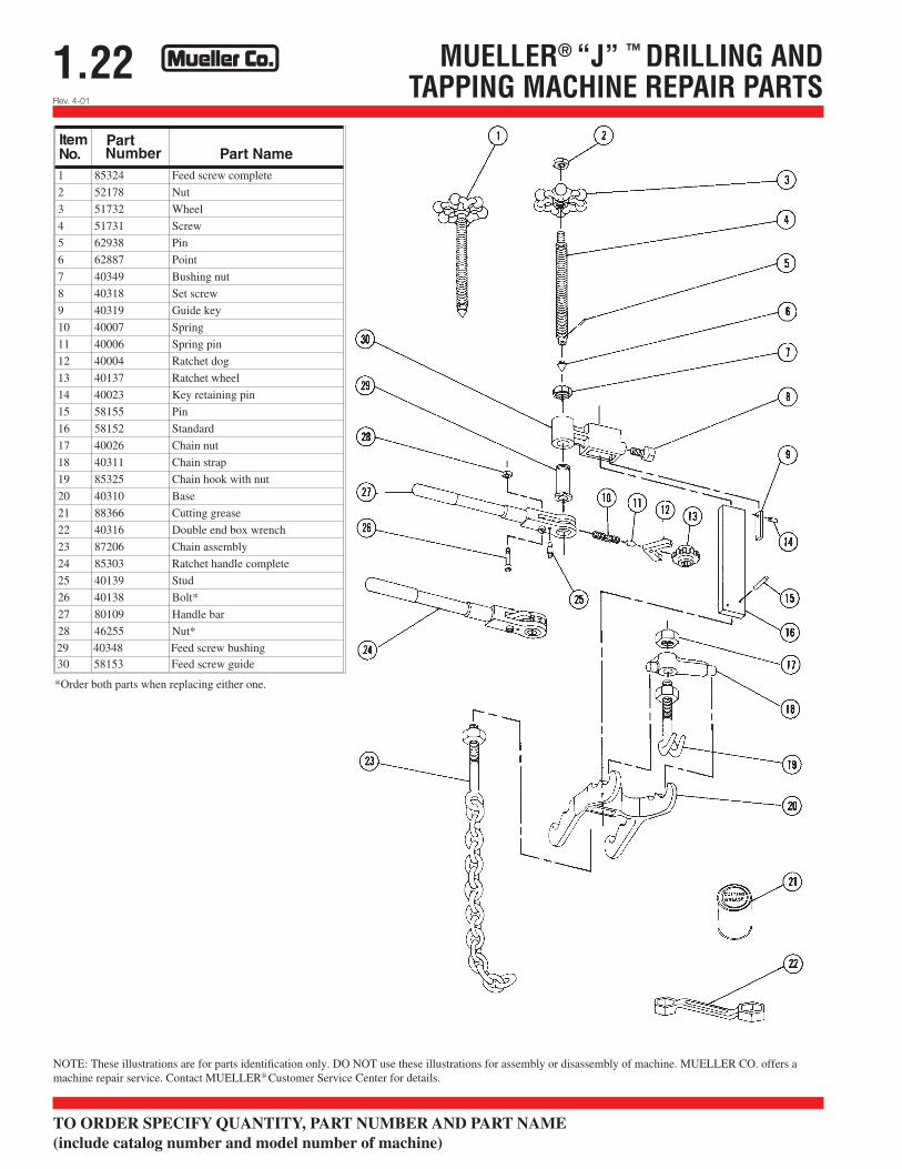
1.22 MUELLER® “J” ™ DRILLING ANDTAPPING MACHINE REPAIR PARTS
ItemNo.
PartNumber Part Name
1 85324 Feed screw complete
2 52178 Nut
3 51732 Wheel
4 51731 Screw
5 62938 Pin
6 62887 Point
7 40349 Bushing nut
8 40318 Set screw
9 40319 Guide key
10 40007 Spring
11 40006 Spring pin
12 40004 Ratchet dog
13 40137 Ratchet wheel
14 40023 Key retaining pin
15 58155 Pin
16 58152 Standard
17 40026 Chain nut
18 40311 Chain strap
19 85325 Chain hook with nut
20 40310 Base
21 88366 Cutting grease
22 40316 Double end box wrench
23 87206 Chain assembly
24 85303 Ratchet handle complete
25 40139 Stud
26 40138 Bolt*
27 80109 Handle bar
28 46255 Nut*
29 40348 Feed screw bushing30 58153 Feed screw guide
Rev. 4-01
*Order both parts when replacing either one.
NOTE: These illustrations are for parts identification only. DO NOT use these illustrations for assembly or disassembly of machine. MUELLER CO. offers a machine repair service. Contact MUELLER® Customer Service Center for details.
TO ORDER SPECIFY QUANTITY, PART NUMBER AND PART NAME (include catalog number and model number of machine)
1.21MUELLER® “J” ™ DRILLING AND TAPPINGMACHINE EQUIPMENT FOR SPECIAL USESMUELLER® “J” Machine equipment for special uses
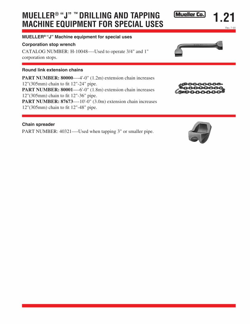
Corporation stop wrench
CATALOG NUMBER: H-10048—-Used to operate 3/4" and 1" corporation stops.
Round link extension chains
PART NUMBER: 80000—-4'-0" (1.2m) extension chain increases 12"(305mm) chain to fit 12"-24" pipe. PART NUMBER: 80001—-6'-0" (1.8m) extension chain increases 12"(305mm) chain to fit 12"-36" pipe. PART NUMBER: 87673—-10'-0" (3.0m) extension chain increases 12"(305mm) chain to fit 12"-48" pipe.
Chain spreader
PART NUMBER: 40321—-Used when tapping 3" or smaller pipe.
Rev. 7-90
1.20Rev. 9-09
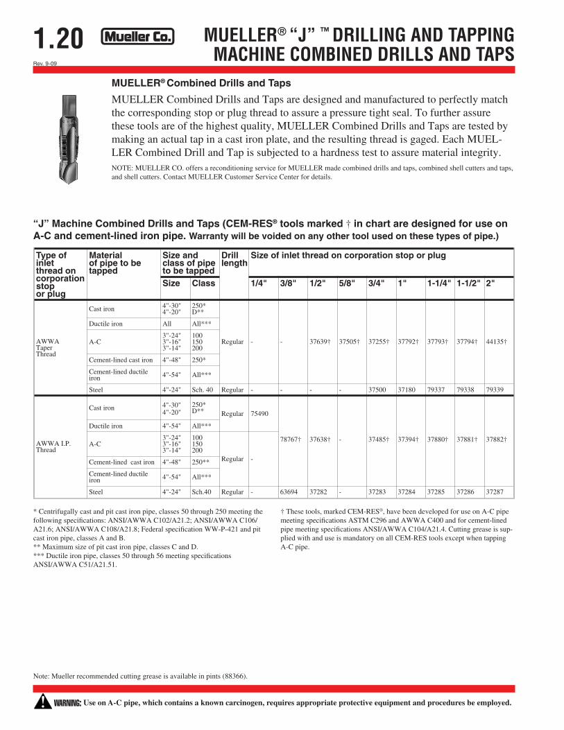
MUELLER® “J” ™ DRILLING AND TAPPINGMACHINE COMBINED DRILLS AND TAPS
Type ofinletthread oncorporationstopor plug
Materialof pipe to betapped
Size andclass of pipeto be tapped
Drilllength
Size of inlet thread on corporation stop or plug
Size Class 1/4" 3/8" 1/2" 5/8" 3/4" 1" 1-1/4" 1-1/2" 2"
AWWATaperThread
Cast iron 4"-30"4"-20"
250*D**
Ductile iron All All***
A-C3"-24"3"-16"3"-14"
100150200
Regular - - 37639† 37505† 37255† 37792† 37793† 37794† 44135†
Cement-lined cast iron 4"-48" 250*
Cement-lined ductileiron 4"-54" All***
Steel 4"-24" Sch. 40 Regular - - - - 37500 37180 79337 79338 79339
AWWA I.P.Thread
Cast iron 4"-30"4"-20"
250*D** Regular 75490
Ductile iron 4"-54" All***
A-C3"-24"3"-16"3"-14"
100150200
Regular -
78767† 37638† - 37485† 37394† 37880† 37881† 37882†
Cement-lined cast iron 4"-48" 250**
Cement-lined ductileiron 4"-54" All***
Steel 4"-24" Sch.40 Regular - 63694 37282 - 37283 37284 37285 37286 37287
MUELLER® Combined Drills and Taps
MUELLER Combined Drills and Taps are designed and manufactured to perfectly match the corresponding stop or plug thread to assure a pressure tight seal. To further assure these tools are of the highest quality, MUELLER Combined Drills and Taps are tested by making an actual tap in a cast iron plate, and the resulting thread is gaged. Each MUEL-LER Combined Drill and Tap is subjected to a hardness test to assure material integrity. NOTE: MUELLER CO. offers a reconditioning service for MUELLER made combined drills and taps, combined shell cutters and taps, and shell cutters. Contact MUELLER Customer Service Center for details.
“J” Machine Combined Drills and Taps (CEM-RES® tools marked † in chart are designed for use on A-C and cement-lined iron pipe. Warranty will be voided on any other tool used on these types of pipe.)
* Centrifugally cast and pit cast iron pipe, classes 50 through 250 meeting the following specifications: ANSI/AWWA C102/A21.2; ANSI/AWWA C106/A21.6; ANSI/AWWA C108/A21.8; Federal specification WW-P-421 and pit cast iron pipe, classes A and B. ** Maximum size of pit cast iron pipe, classes C and D. *** Ductile iron pipe, classes 50 through 56 meeting specifications ANSI/AWWA C51/A21.51.
† These tools, marked CEM-RES®, have been developed for use on A-C pipe meeting specifications ASTM C296 and AWWA C400 and for cement-lined pipe meeting specifications ANSI/AWWA C104/A21.4. Cutting grease is sup-plied with and use is mandatory on all CEM-RES tools except when tapping A-C pipe.
Note: Mueller recommended cutting grease is available in pints (88366).
WARNING: Use on A-C pipe, which contains a known carcinogen, requires appropriate protective equipment and procedures be employed.
Rev. 9-09
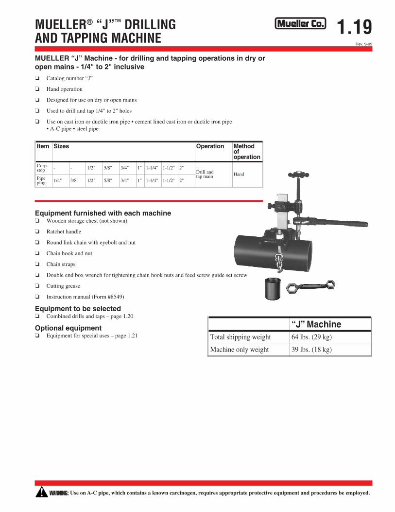
1.19MUELLER® “J”™ DRILLINGAND TAPPING MACHINE
Item Sizes Operation Methodofoperation
Corp.stop - - 1/2" 5/8" 3/4" 1" 1-1/4" 1-1/2" 2"
Drill andtap main Hand
Pipeplug 1/4" 3/8" 1/2" 5/8" 3/4" 1" 1-1/4" 1-1/2" 2"
“J” MachineTotal shipping weight 64 lbs. (29 kg)
Machine only weight 39 lbs. (18 kg)
MUELLER “J” Machine - for drilling and tapping operations in dry or open mains - 1/4" to 2" inclusive
o Catalog number “J”
o Hand operation
o Designed for use on dry or open mains
o Used to drill and tap 1/4" to 2" holes
o Use on cast iron or ductile iron pipe • cement lined cast iron or ductile iron pipe • A-C pipe • steel pipe
Equipment furnished with each machine o Wooden storage chest (not shown)
o Ratchet handle
o Round link chain with eyebolt and nut
o Chain hook and nut
o Chain straps
o Double end box wrench for tightening chain hook nuts and feed screw guide set screw
o Cutting grease
o Instruction manual (Form #8549)
Equipment to be selected o Combined drills and taps – page 1.20
Optional equipment o Equipment for special uses – page 1.21
WARNING: Use on A-C pipe, which contains a known carcinogen, requires appropriate protective equipment and procedures be employed.
1.18Rev. 8-04 Shaded area indicates change
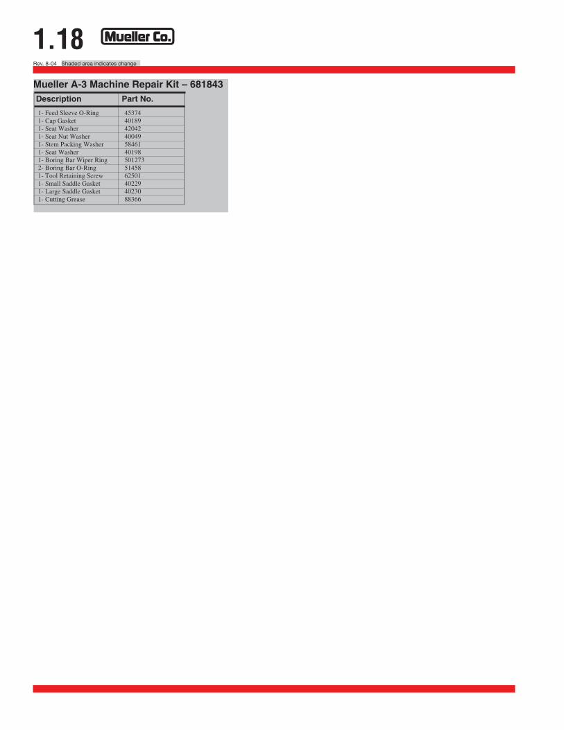
1- Feed Sleeve O-Ring 453741- Cap Gasket 401891- Seat Washer 420421- Seat Nut Washer 400491- Stem Packing Washer 584611- Seat Washer 401981- Boring Bar Wiper Ring 5012732- Boring Bar O-Ring 514581- Tool Retaining Screw 625011- Small Saddle Gasket 402291- Large Saddle Gasket 402301- Cutting Grease 88366
Mueller A-3 Machine Repair Kit – 681843Description Part No.
1.17Shaded area indicates change Rev. 8-04
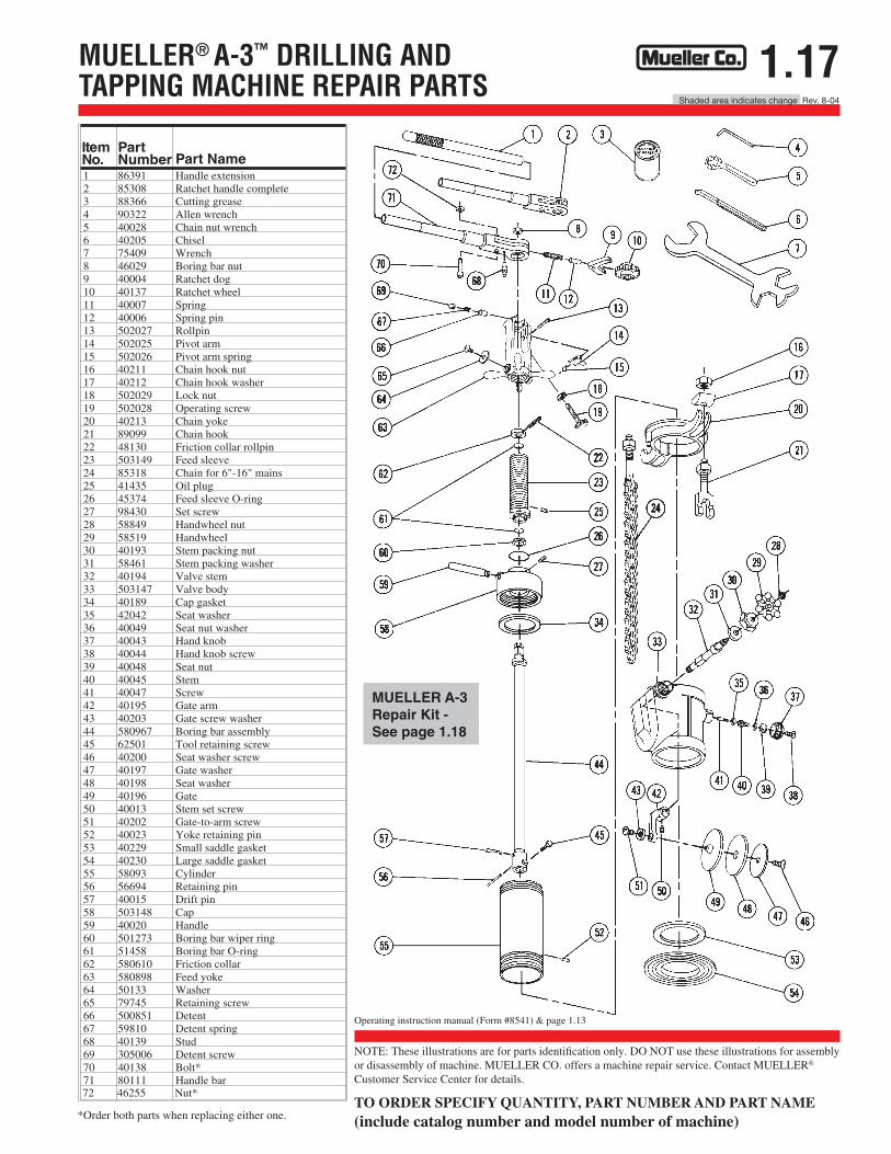
MUELLER® A-3™ DRILLING ANDTAPPING MACHINE REPAIR PARTS
ItemNo.
PartNumber Part Name
1 86391 Handle extension2 85308 Ratchet handle complete3 88366 Cutting grease4 90322 Allen wrench5 40028 Chain nut wrench6 40205 Chisel7 75409 Wrench8 46029 Boring bar nut9 40004 Ratchet dog10 40137 Ratchet wheel11 40007 Spring12 40006 Spring pin13 502027 Rollpin14 502025 Pivot arm15 502026 Pivot arm spring16 40211 Chain hook nut17 40212 Chain hook washer18 502029 Lock nut19 502028 Operating screw20 40213 Chain yoke21 89099 Chain hook22 48130 Friction collar rollpin23 503149 Feed sleeve24 85318 Chain for 6"-16" mains25 41435 Oil plug26 45374 Feed sleeve O-ring27 98430 Set screw28 58849 Handwheel nut29 58519 Handwheel30 40193 Stem packing nut31 58461 Stem packing washer32 40194 Valve stem33 503147 Valve body34 40189 Cap gasket35 42042 Seat washer36 40049 Seat nut washer37 40043 Hand knob38 40044 Hand knob screw39 40048 Seat nut40 40045 Stem41 40047 Screw42 40195 Gate arm43 40203 Gate screw washer44 580967 Boring bar assembly45 62501 Tool retaining screw46 40200 Seat washer screw47 40197 Gate washer48 40198 Seat washer49 40196 Gate50 40013 Stem set screw51 40202 Gate-to-arm screw52 40023 Yoke retaining pin53 40229 Small saddle gasket54 40230 Large saddle gasket55 58093 Cylinder56 56694 Retaining pin57 40015 Drift pin58 503148 Cap59 40020 Handle60 501273 Boring bar wiper ring61 51458 Boring bar O-ring62 580610 Friction collar63 580898 Feed yoke64 50133 Washer65 79745 Retaining screw66 500851 Detent67 59810 Detent spring68 40139 Stud69 305006 Detent screw70 40138 Bolt*71 80111 Handle bar72 46255 Nut*
NOTE: These illustrations are for parts identification only. DO NOT use these illustrations for assembly or disassembly of machine. MUELLER CO. offers a machine repair service. Contact MUELLER® Customer Service Center for details.
TO ORDER SPECIFY QUANTITY, PART NUMBER AND PART NAME (include catalog number and model number of machine) *Order both parts when replacing either one.
MUELLER A-3 Repair Kit - See page 1.18
Operating instruction manual (Form #8541) & page 1.13
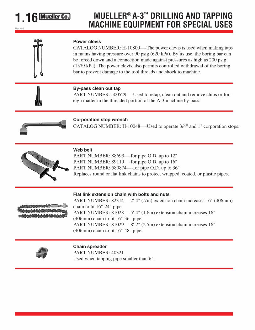
1.16 MUELLER® A-3™ DRILLING AND TAPPINGMACHINE EQUIPMENT FOR SPECIAL USES
Power clevis
By-pass clean out tap
Corporation stop wrench
Web belt
Flat link extension chain with bolts and nuts
Chain spreader
CATALOG NUMBER: H-10800—-The power clevis is used when making taps in mains having pressure over 90 psig (620 kPa). By its use, the boring bar can be forced down and a connection made against pressures as high as 200 psig (1379 kPa). The power clevis also permits controlled withdrawal of the boring bar to prevent damage to the tool threads and shock to machine.
PART NUMBER: 500529—-Used to retap, clean out and remove chips or for-eign matter in the threaded portion of the A-3 machine by-pass.
CATALOG NUMBER: H-10048—-Used to operate 3/4" and 1" corporation stops.
PART NUMBER: 88693—-for pipe O.D. up to 12" PART NUMBER: 89119—-for pipe O.D. up to 16" PART NUMBER: 580874—-for pipe O.D. up to 36" Replaces round or flat link chains to protect wrapped, coated, or plastic pipes.
PART NUMBER: 82314—-2'-4" (.7m) extension chain increases 16" (406mm) chain to fit 16"-24" pipe. PART NUMBER: 81028—-5'-4" (1.6m) extension chain increases 16" (406mm) chain to fit 16"-36" pipe. PART NUMBER: 81029—-8'-2" (2.5m) extension chain increases 16" (406mm) chain to fit 16"-48" pipe.
PART NUMBER: 40321 Used when tapping pipe smaller than 6".
Rev. 4-91
Rev. 9-09
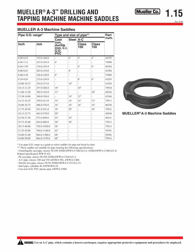
1.15MUELLER® A-3™ DRILLING AND TAPPING MACHINE MACHINE SADDLES
MUELLER A-3 Machine SaddlesPipe O.D. range* Type and size of pipe** Part
num.Castiron,ductileiron, C.I.O.D.PVC
Steel A-CInch mm Class
100Class150
6.00-6.63 152.0-168.0 - 6" 4" 4" 46703
6.56-7.13 167.0-181.0 6" - - - 75908
6.94-7.50 176.0-191.0 - - 6" 6" 46704
8.00-8.63 203.0-219.0 - 8" - - 45384
8.88-9.38 226.0-238.0 8" - - - 75909
9.19-9.63 233.0-245.0 - - 8" 8" 43293
10.00-10.75 254.0-273.0 - 10" - - 43294
10.13-11.25 257.0-286.0 10" - 10" - 75910
11.88-13.50 302.0-343.0 12" - - 10" 40236
13.38-14.00 340.0-356.0 - 14" 12" - 43364
14.13-16.25 359.0-413.0 14" 16" 14" 12" 75911
16.00-18.75 406.0-476.0 16" 18" 16" 14" 40238
17.75-20.50 451.0-521.0 18" 20" - 16" 75831
18.13-22.75 461.0-578.0 20" - - - 40240
22.50-27.50 572.0-699.0 24" 24" - - 40241
25.75-35.00 654.0-889.0 30" 30" - - 75912
30.13-40.00 765.0-1020.0 36" - - - 75913
31.25-45.00 794.0-1140.0 42" - - - 76701
34.00-51.00 864.0-1300.0 48" - - - 5958234.00-58.00 864.0-1470.0 48" - - - 75914
MUELLER® A-3 Machine Saddles
* Use pipe O.D. range as a guide to select saddles for pipe not listed in chart. ** These saddles are suitable for pipe meeting the following specifications: - Centrifugally cast pipe, classes 50-250 ANSI/AWWA C106/A21.6; ANSI/AWWA C108/A21.8; Federal specification WW-P-421. - Pit cast pipe, classes 50-250 ANSI/AWWA C102/A21.2. - A-C pipe, classes 100 and 150 ASTM C296, AWWA C400. - Ductile iron pipe, classes 50-56 ANSI/AWWA C151/A21.51. - Steel pipe, schedule 40 ASTM B36.10. - Cast iron O.D. PVC plastic pipe AWWA C900.
WARNING: Use on A-C pipe, which contains a known carcinogen, requires appropriate protective equipment and procedures be employed.
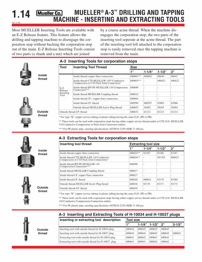
1.14 MUELLER® A-3™ DRILLING AND TAPPINGMACHINE - INSERTING AND EXTRACTING TOOLS
A-3 Inserting Tools for corporation stopsTool Inserting Tool Thread Size
1" 1-1/4" 1-1/2" 2"
E-ZReleaseInsertingTool
Inside thread-copper flare connection 680601** 680602 88640 88641
Inside thread-CTS MUELLER 110® ConductiveCompression or CTS Pack Joint Connection*
680601** - 680421 680422
Inside thread-IPS PE MUELLER 110 CompressionConnection***
680689 - - -
Inside thread-MUELLER Coupling thread 680612 - - -
Inside thread I.P.- copper flare connection 680604 - - -
Inside thread-I.P. thread 680596 680597 83065 83066
Outside thread-MUELLER Screw Plug thread 680655 58482 58483 58484
Outside thread-I.P. thread 680632 61212 61213 61214
A-3 Extracting Tools for corporation stopsInserting tool thread Extracting tool size
1" 1-1/4" 1-1/2" 2"Inside thread-copper flare connection 680624** 83185 83186 83187
Inside thread-CTS MUELLER 110 ConductiveCompression or CTS Pack Joint Connections*
680624** - 581765 680423
Inside thread-IPS PE MUELLER 110Compression Connection***
680690 - - -
Inside thread-MUELLER Coupling thread 680617 - - -
Inside thread-I.P. copper flare connection 680627 - - -
Inside thread-I.P. thread 680620 680621 83179 83180
Outside thread-MUELLER Screw Plug thread 680636 83170 83171 83172
Outside thread-I.P. thread 680639 - - -
Inserting or extracting tool description Tool size1" 1-1/4" 1-1/2" 2" 2-1/2"
Inserting tool-with outside thread for H-10034 plug 680644 680645 680645 680645 -
Inserting tool-with outside thread for H-10037 plug 680644 680644 680645 680645 680645
Extracting tool-with outside thread for H-10034 plug 680641 680642 680642 680642 -
Extracting tool-with outside thread for H-10037 plug 680641 680641 680642 680642 -
A-3 Inserting and Extracting Tools of H-10034 and H-10037 plugs
Most MUELLER Inserting Tools are available with an E-Z Release feature. This feature allows the drilling and tapping machine to disengage the cor-poration stop without backing the corporation stop out of the main. E-Z Release Inserting Tools consist of two parts (a shank and a nut) which are joined
by a coarse acme thread. When the machine dis-engages the corporation stop, the two parts of the inserting tool seperate at the acme thread. The part of the inserting tool left attached to the corporation stop is easily removed once the tapping machine is removed from the main.
* For type “K” copper service tubing or plastic tubing having the same O.D. (PE or PB).
** These tools can be used with corporation stops having either copper service thread outlet or CTS O.D. MUELLER 110 Conductive Compression or Pack Joint Connection outlets.
*** For PE plastic pipe, meeting specifications ASTM D-2239 (SDR-7) 160 psi.
* For type “K” copper service tubing or plastic tubing having the same O.D. (PE or PB).
** These tools can be used with corporation stops having either copper service thread outlet or CTS O.D. MUELLER 110 Conductive Compression Connection outlets.
*** For PE plastic pipe, meeting specifications ASTM D-2239 (SDR-7) 160 psi.
Rev. 4-99
Outside thread
Outside thread
Outside thread
Insidethread
Insidethread
Shaded area indicates change Rev. 9-09
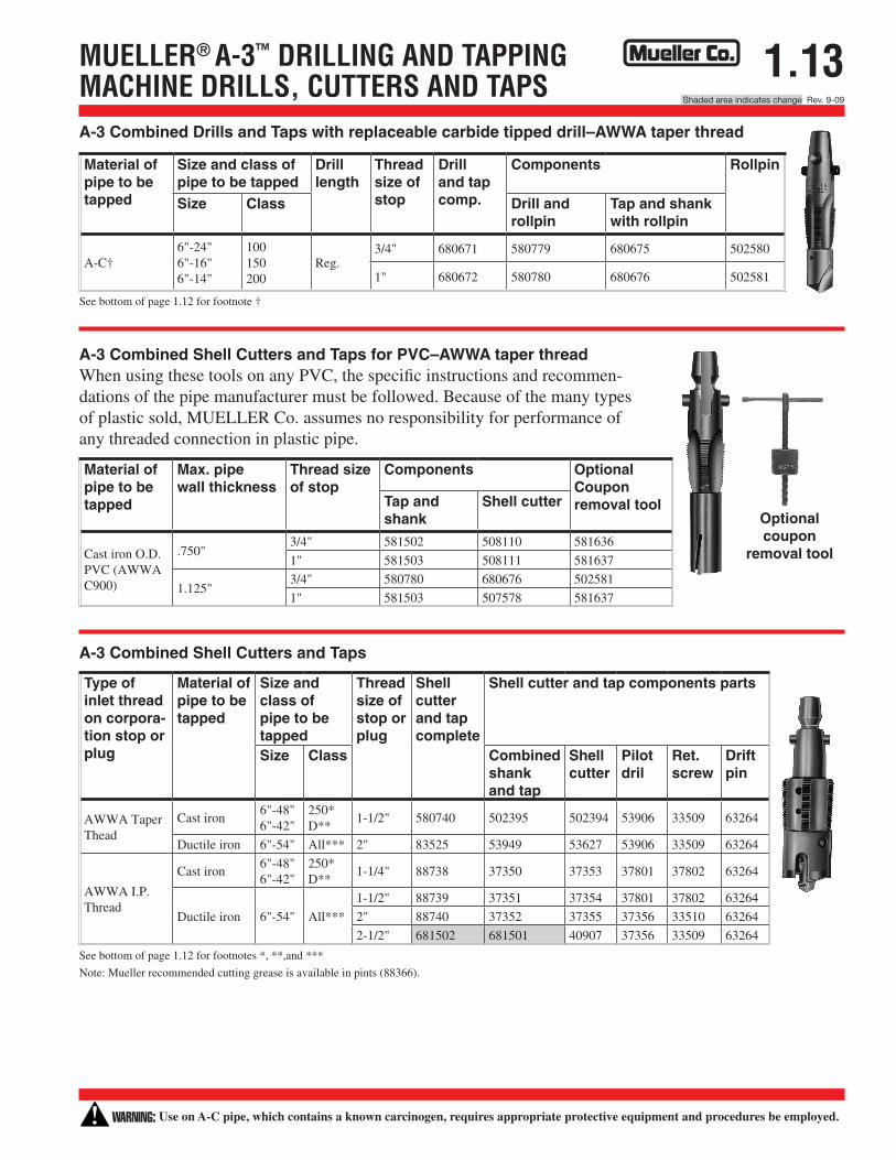
1.13MUELLER® A-3™ DRILLING AND TAPPINGMACHINE DRILLS, CUTTERS AND TAPSA-3 Combined Drills and Taps with replaceable carbide tipped drill–AWWA taper thread
See bottom of page 1.12 for footnote †
A-3 Combined Shell Cutters and Taps for PVC–AWWA taper thread When using these tools on any PVC, the specific instructions and recommen-dations of the pipe manufacturer must be followed. Because of the many types of plastic sold, MUELLER Co. assumes no responsibility for performance of any threaded connection in plastic pipe.
A-3 Combined Shell Cutters and Taps
Optional coupon
removal tool
See bottom of page 1.12 for footnotes *, **,and ***
Note: Mueller recommended cutting grease is available in pints (88366).
Material of pipe to be tapped
Size and class of pipe to be tapped
Drill length
Thread size of stop
Drill and tap comp.
Components Rollpin
Size Class Drill and rollpin
Tap and shank with rollpin
A-C†6"-24"6"-16"6"-14"
100150200
Reg.3/4" 680671 580779 680675 502580
1" 680672 580780 680676 502581
Material of pipe to be tapped
Max. pipe wall thickness
Thread size of stop
Components Optional Coupon removal toolTap and
shankShell cutter
Cast iron O.D. PVC (AWWA C900)
.750"3/4" 581502 508110 581636
1" 581503 508111 581637
1.125"3/4" 580780 680676 502581
1" 581503 507578 581637
Type of inlet thread on corpora-tion stop or plug
Material of pipe to be tapped
Size and class of pipe to be tapped
Thread size of stop or plug
Shell cutter and tap complete
Shell cutter and tap components parts
Size Class Combined shank and tap
Shell cutter
Pilot dril
Ret. screw
Drift pin
AWWA Taper Thead
Cast iron6"-48"6"-42"
250*D**
1-1/2" 580740 502395 502394 53906 33509 63264
Ductile iron 6"-54" All*** 2" 83525 53949 53627 53906 33509 63264
AWWA I.P. Thread
Cast iron6"-48"6"-42"
250*D**
1-1/4" 88738 37350 37353 37801 37802 63264
Ductile iron 6"-54" All***
1-1/2" 88739 37351 37354 37801 37802 63264
2" 88740 37352 37355 37356 33510 63264
2-1/2" 681502 681501 40907 37356 33509 63264
WARNING: Use on A-C pipe, which contains a known carcinogen, requires appropriate protective equipment and procedures be employed.
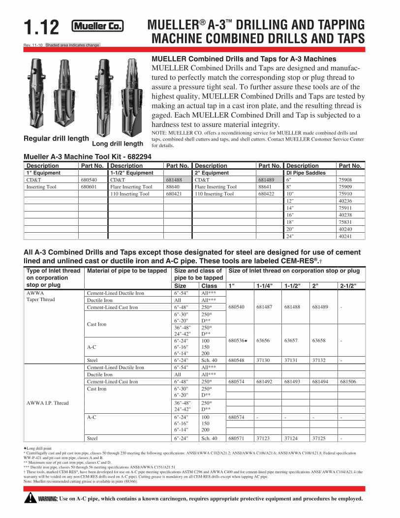
1.12 MUELLER® A-3™ DRILLING AND TAPPINGMACHINE COMBINED DRILLS AND TAPSMUELLER Combined Drills and Taps for A-3 Machines MUELLER Combined Drills and Taps are designed and manufac-tured to perfectly match the corresponding stop or plug thread to assure a pressure tight seal. To further assure these tools are of the highest quality, MUELLER Combined Drills and Taps are tested by making an actual tap in a cast iron plate, and the resulting thread is gaged. Each MUELLER Combined Drill and Tap is subjected to a hardness test to assure material integrity. NOTE: MUELLER CO. offers a reconditioning service for MUELLER made combined drills and taps, combined shell cutters and taps, and shell cutters. Contact MUELLER Customer Service Center for details.
All A-3 Combined Drills and Taps except those designated for steel are designed for use of cement lined and unlined cast or ductile iron and A-C pipe. These tools are labeled CEM-RES®.†
Regular drill length Long drill length
Long drill point* Centrifugally cast and pit cast iron pipe, classes 50 through 250 meeting the following specifications: ANSI/AWWA C102/A21.2; ANSI/AWWA C106/A21.6; ANSI/AWWA C108/A21.8; Federal specification WW-P-421 and pit cast iron pipe, classes A and B. ** Maximum size of pit cast iron pipe, classes C and D. *** Ductile iron pipe, classes 50 through 56 meeting specifications ANSI/AWWA C151/A21.51 † These tools, marked CEM-RES®, have been developed for use on A-C pipe meeting specifications ASTM C296 and AWWA C400 and for cement-lined pipe meeting specifications ANSI/ AWWA C104/A21.4 (the warranty will be voided on any non-CEM-RES drills used on A-C pipe). Cutting grease is mandatory on all CEM-RES drills except when tapping AC pipe. Note: Mueller recommended cutting grease is available in pints (88366).
Type of Inlet thread on corporation stop or plug
Material of pipe to be tapped Size and class of pipe to be tapped
Size of Inlet thread on corporation stop or plug
Size Class 1" 1-1/4" 1-1/2" 2" 2-1/2"AWWATaper Thread
Cement-Lined Ductile Iron 6"-54" All***
680540 681487 681488 681489 -Ductile Iron All All***Cement-Lined Cast Iron 6"-48" 250*
Cast Iron
6"-30"6"-20"
250*D**
36"-48"24"-42"
250*D**
680536 63656 63657 63658 -A-C
6"-24"6"-16"6"-14"
100150200
Steel 6"-24" Sch. 40 680548 37130 37131 37132 -
AWWA I.P. Thread
Cement-Lined Ductile Iron 6"-54" All***Ductile Iron All All***Cement-Lined Cast Iron 6"-48" 250* 680574 681492 681493 681494 681506Cast Iron 6"-30"
6"-20"250*D**
36"-48"24"-42"
250*D**
A-C 6"-24"6"-16"6"-14"
100150200
680574 - - - -
Steel 6"-24" Sch. 40 680571 37123 37124 37125 -
Mueller A-3 Machine Tool Kit - 682294Description Part No. Description Part No. Description Part No. Description Part No.1" Equipment 1-1/2" Equipment 2" Equipment DI Pipe SaddlesCD&T 680540 CD&T 681488 CD&T 681489 6" 75908Inserting Tool 680601 Flare Inserting Tool 88640 Flare Inserting Tool 88641 8" 75909
110 Inserting Tool 680421 110 Inserting Tool 680422 10" 7591012" 4023614" 7591116" 4023818" 7583120" 4024024" 40241
WARNING: Use on A-C pipe, which contains a known carcinogen, requires appropriate protective equipment and procedures be employed.
Rev. 9-09
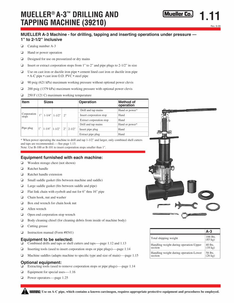
1.11MUELLER® A-3™ DRILLING ANDTAPPING MACHINE (39210)
A-3
Total shipping weight 188 lbs.(85 kg)
Handling weight during operation-Uppersection
40 lbs.(18 kg)
Handling weight during operation-Lowersection
58 lbs.(26 kg)
MUELLER A-3 Machine - for drilling, tapping and inserting operations under pressure — 1" to 2-1/2" inclusive o Catalog number A-3
o Hand or power operation
o Designed for use on pressurized or dry mains
o Insert or extract corporation stops from 1" to 2" and pipe plugs to 2-1/2" in size
o Use on cast iron or ductile iron pipe • cement lined cast iron or ductile iron pipe • A-C pipe • cast iron O.D. PVC • steel pipe
o 90 psig (621 kPa) maximum working pressure without optional power clevis
o 200 psig (1379 kPa) maximum working pressure with optional power clevis
o 250 F (121 C) maximum working temperature
* When power operating the machine to drill and tap 1-1/2" and larger, only combined shell cutters and taps are recommended.—-See page 1.13. Note: Use B-100 or B-101 to insert corporation stops smaller than 1".
Equipment furnished with each machine: o Wooden storage chest (not shown)
o Ratchet handle
o Ratchet handle extension
o Small saddle gasket (fits between machine and saddle)
o Large saddle gasket (fits between saddle and pipe)
o Flat link chain with eyebolt and nut for 6" thru 16" pipe
o Chain hook, nut and washer
o Box end wrench for chain hook nut
o Allen wrench
o Open end corporation stop wrench
o Body cleaning chisel (for cleaning debris from inside of machine body)
o Cutting grease
o Instruction manual (Form #8541)
Equipment to be selected: o Combined drills and taps or shell cutters and taps—-page 1.12 and 1.13
o Inserting tools (used to insert corporation stops or pipe plugs)—-page 1.14
o Machine saddles (adapts machine to specific type and size of main)—-page 1.15
Optional equipment: o Extracting tools (used to remove corporation stops or pipe plugs)—-page 1.14
o Equipment for special uses—-1.16
o Power operators—-page 1.25
Item Sizes Operation Method ofoperation
Corporationstops 1"
Drill and tap mains Hand or power*
Insert corporation stop Hand
Extract corporation stop Hand
Pipe plugDrill and tap mains Hand or power*
Insert pipe plug Hand
Extract pipe plug Hand
1-1/4" 1-1/2" 2"
1" 1-1/4" 1-1/2" 2" 2-1/2"
WARNING: Use on A-C pipe, which contains a known carcinogen, requires appropriate protective equipment and procedures be employed.
1.10Rev. 9-09 Shaded area indicates change
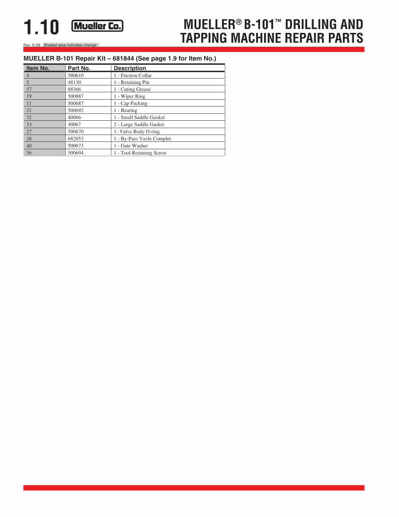
MUELLER® B-101™ DRILLING ANDTAPPING MACHINE REPAIR PARTS
Item No. Part No. Description4 580610 1 - Friction Collar5 48130 1 - Retaining Pin57 88366 1 - Cuting Grease19 500887 1 - Wiper Ring11 500687 1 - Cap Packing21 500692 1 - Bearing32 40066 1 - Small Saddle Gaxket 33 40067 2 - Large Saddle Gasket 27 500670 1- Valve Body O-ring28 682053 1 - By-Pass Vavle Complet40 500673 1 - Gate Washer56 500694 1 - Tool Retaining Screw
MUELLER B-101 Repair Kit – 681844 (See page 1.9 for Item No.)
Shaded area indicates change Rev. 9-09
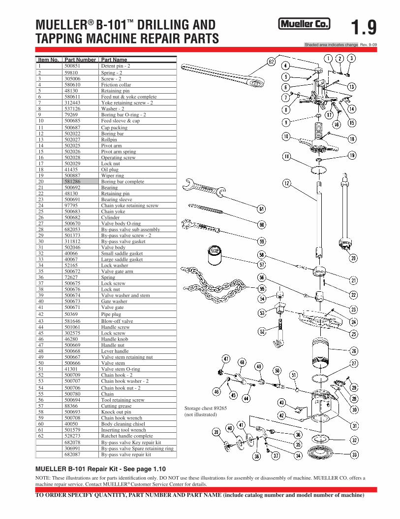
1.9MUELLER® B-101™ DRILLING ANDTAPPING MACHINE REPAIR PARTS
Storage chest 89265 (not illustrated)
NOTE: These illustrations are for parts identification only. DO NOT use these illustrations for assembly or disassembly of machine. MUELLER CO. offers a machine repair service. Contact MUELLER® Customer Service Center for details.
TO ORDER SPECIFY QUANTITY, PART NUMBER AND PART NAME (include catalog number and model number of machine)
MUELLER B-101 Repair Kit - See page 1.10
Item No. Part Number Part Name1 500851 Detent pin - 22 59810 Spring - 23 305006 Screw - 24 580610 Friction collar5 48130 Retaining pin6 580611 Feed nut & yoke complete7 312443 Yoke retaining screw - 28 537126 Washer - 29 79269 Boring bar O-ring - 210 500685 Feed sleeve & cap11 500687 Cap packing12 502022 Boring bar13 502027 Rollpin14 502025 Pivot arm15 502026 Pivot arm spring16 502028 Operating screw17 502029 Lock nut18 41435 Oil plug19 500887 Wiper ring20 581286 Boring bar complete21 500692 Bearing22 48130 Retaining pin23 500691 Bearing sleeve24 97795 Chain yoke retaining screw25 500683 Chain yoke26 500682 Cylinder27 500670 Valve body O-ring28 682053 By-pass valve sub assembly29 501373 By-pass valve screw - 230 311812 By-pass valve gasket31 502046 Valve body32 40066 Small saddle gasket33 40067 Large saddle gasket34 52165 Lock washer35 500672 Valve gate arm36 72627 Spring37 500675 Lock screw38 500676 Lock nut39 500674 Valve washer and stem40 500673 Gate washer41 500671 Valve gate42 50369 Pipe plug43 581646 Blow-off valve44 501061 Handle screw45 302575 Lock screw46 46280 Handle knob47 500669 Handle nut48 500668 Lever handle49 500667 Valve stem retaining nut50 500666 Valve stem51 41301 Valve stem O-ring52 500709 Chain hook - 253 500707 Chain hook washer - 254 500706 Chain hook nut - 255 500780 Chain56 500694 Tool retaining screw57 88366 Cutting grease58 500693 Knock out pin59 500708 Chain hook wrench60 40050 Body cleaning chisel61 501579 Inserting tool wrench62 528273 Ratchet handle complete
682078 By-pass valve Key repair kit306991 By-pass valve Spare retaining ring682087 By-pass valve repair kit
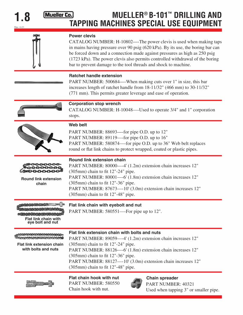
1.8 MUELLER® B-101™ DRILLING ANDTAPPING MACHINES SPECIAL USE EQUIPMENT
CATALOG NUMBER: H-10802—-The power clevis is used when making taps in mains having pressure over 90 psig (620 kPa). By its use, the boring bar can be forced down and a connection made against pressures as high as 250 psig (1723 kPa). The power clevis also permits controlled withdrawal of the boring bar to prevent damage to the tool threads and shock to machine.
PART NUMBER: 500684—-When making cuts over 1" in size, this bar increases length of ratchet handle from 18-11/32" (466 mm) to 30-11/32" (771 mm). This permits greater leverage and ease of operation.
Power clevis
Ratchet handle extension
Corporation stop wrench CATALOG NUMBER: H-10048—-Used to operate 3/4" and 1" corporation stops.
Web belt
PART NUMBER: 88693—-for pipe O.D. up to 12" PART NUMBER: 89119—-for pipe O.D. up to 16" PART NUMBER: 580874—-for pipe O.D. up to 36" Web belt replaces round or flat link chains to protect wrapped, coated or plastic pipes.
Round link extension chain PART NUMBER: 80000—-4' (1.2m) extension chain increases 12" (305mm) chain to fit 12"-24" pipe. PART NUMBER: 80001—-6' (1.8m) extension chain increases 12" (305mm) chain to fit 12"-36" pipe. PART NUMBER: 87673—-10' (3.0m) extension chain increases 12" (305mm) chain to fit 12"-48" pipe.
Flat link chain with eyebolt and nut
Flat link extension chain with bolts and nuts
PART NUMBER: 580551—-For pipe up to 12".
PART NUMBER: 89059—-4' (1.2m) extension chain increases 12" (305mm) chain to fit 12"-24" pipe. PART NUMBER: 88126—-6' (1.8m) extension chain increases 12" (305mm) chain to fit 12"-36" pipe. PART NUMBER: 88127—-10' (3.0m) extension chain increases 12" (305mm) chain to fit 12"-48" pipe.
Flat link extension chain with bolts and nuts
Flat chain hook with nut Chain spreader PART NUMBER: 580550 Chain hook with nut.
PART NUMBER: 40321 Used when tapping 3" or smaller pipe.
Rev. 4-01
Flat link chain with eye bolt and nut
Round link extension chain
Rev. 9-09
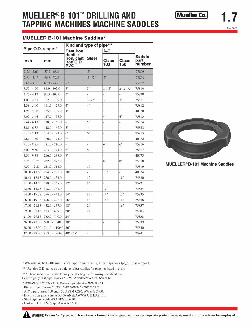
1.7MUELLER® B-101™ DRILLING ANDTAPPING MACHINES MACHINE SADDLES
Pipe O.D. range**Kind and type of pipe***
Saddlepartnumber
Cast iron,ductileiron, castiron O.D.PVC
Steel
A-C
Inch mm Class100
Class150
3.50 - 4.00 88.9 - 102.0 3" 3" 2-1/2" 2"-2-1/2" 75810
3.75 - 4.13 95.3 - 105.0 3" - - - 75830
4.00 - 4.31 102.0 - 109.0 - 3-1/2" 3" 3" 75811
4.38 - 5.00 111.0 - 127.0 4" 4" - - 75812
4.94 - 5.38 125.0 - 137.0 4" - - - 40070
5.00 - 5.44 127.0 - 138.0 - - 4" 4" 75813
5.44 - 6.13 138.0 - 156.0 - 5" - - 75814
5.81 - 6.38 148.0 - 162.0 5" - - - 75833
6.44 - 7.13 164.0 - 181.0 6" 6" - - 75815
6.69 - 7.50 170.0 - 191.0 6" - - - 40072
7.13 - 8.25 181.0 - 210.0 - - 6" 6" 75816
8.00 - 9.50 203.0 - 241.0 8" 8" - - 75817
8.50 - 9.38 216.0 - 238.0 8" - - - 40073
8.75 - 10.75 222.0 - 273.0 - - 8" 8" 75818
9.50 - 12.25 241.0 - 311.0 - 10" - - 75819
10.00 - 11.63 254.0 - 295.0 10" - 10" - 40074
10.63 - 13.13 270.0 - 334.0 - 12" - 10" 75820
11.00 - 14.50 279.0 - 368.0 12" 14" - - 75821
12.50 - 14.25 318.0 - 362.0 - - 12" - 75834
14.00 - 17.38 356.0 - 442.0 14" 16" 14" 12" 75835
16.00 - 19.38 406.0 - 492.0 16" 18" 16" 14" 75836
17.00 - 21.13 432.0 - 537.0 18" 20" - 16" 75837
19.00 - 27.13 483.0 - 689.0 20" 24" - - 75204
21.00 - 29.13 533.0 - 740.0 24" - - - 75838
26.00 - 41.00 660.0 - 1040.0 30" 30" - - 75839
28.00 - 47.00 711.0 - 1190.0 36" - - - 75840
32.00 - 77.00 813.0 - 1960.0 40" - 48" - - - 75841
MUELLER B-101 Machine Saddles*
2.25 - 2.69 57.2 - 68.3 2" 75808
2.63 - 3.13 66.8 - 79.5 2-1/2" 75809
2.69 - 3.00 68.3 - 76.2 2" 75832
2"
- - -
-
-
- -
MUELLER® B-101 Machine Saddles
* When using the B-101 machine on pipe 3" and smaller, a chain spreader (page 1.8) is required.
** Use pipe O.D. range as a guide to select saddles for pipe not listed in chart.
*** These saddles are suitable for pipe meeting the following specifications: Centrifugally cast pipe, classes 50-250 ANSI/AWWAC106/A21.6;
ANSI/AWWAC108/A21.8; Federal specification WW-P-421. - Pit cast pipe, classes 50-250 ANSI/AWWA C102/A21.2. - A-C pipe, classes 100 and 150 ASTM C296, AWWA C400. - Ductile iron pipe, classes 50-56 ANSI/AWWA C151/A21.51. - Steel pipe, schedule 40 ASTM B36.10. - Cast iron O.D. PVC pipe AWWA C900.
WARNING: Use on A-C pipe, which contains a known carcinogen, requires appropriate protective equipment and procedures be employed.
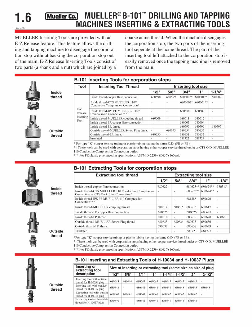
1.6 MUELLER® B-101™ DRILLING AND TAPPINGMACHINES INSERTING & EXTRACTING TOOLS
B-101 Inserting and Extracting Tools of H-10034 and H-10037 PlugsInserting orextracting tooldescription
Size of inserting or extracting tool (same size as size of plug
1/2" 5/8" 3/4" 1" 1-1/4" 1-1/2" 2" 2-1/2"
680643 680644 680644 680644 680645 680645 680645 -
680643 - 680644 680644 680644 680645 680645 680645
680640 680641 680641 680641 680642 680642 680642 -
680640 - 680641 680641 680641 680642 680642 -
Inserting tool-with outsidethread for H-10034 plugInserting tool-with outsidethread for H-10037 plugExtracting tool-with outsidethread for H-10034 plugExtracting tool-with outsidethread for H-10037 plug
MUELLER Inserting Tools are provided with an E-Z Release feature. This feature allows the drill-ing and tapping machine to disengage the corpora-tion stop without backing the corporation stop out of the main. E-Z Release Inserting Tools consist of two parts (a shank and a nut) which are joined by a
coarse acme thread. When the machine disengages the corporation stop, the two parts of the inserting tool seperate at the acme thread. The part of the inserting tool left attached to the corporation stop is easily removed once the tapping machine is removed from the main.
Tool Inserting Tool Thread Inserting tool size1/2" 5/8" 3/4" 1" 1-1/4"
B-101 Inserting Tools for corporation stops
E-ZReleaseInsertingTool
Inside thread-copper flare connection 680598 680599 680600** 680601** 680602
Inside thread-CTS MUELLER 110® - - 680600** 680601** -Conductive Compression Connection*
Inside thread-IPS PE MUELLER 110® - - 680688 680689 -Compression Connection***
Inside thread-MUELLER coupling thread 680609 - 680611 680612 -Inside thread-I.P. copper flare connection - - 680603 680604 -Inside thread-I.P. thread - - 680595 680596 680597Outside thread-MUELLER Screw Plug thread - 680653 680654 680655 -Outside thread-I.P. thread 680630 - 680631 680632 -Insulated - - 681722 681724 -
* For type “K” copper service tubing or plastic tubing having the same O.D. (PE or PB). ** These tools can be used with corporation stops having either copper service thread outlet or CTS O.D. MUELLER 110 Conductive Compression Connection outlet. *** For PE plastic pipe, meeting specifications ASTM D-2239 (SDR-7) 160 psi.
*For type “K” copper service tubing or plastic tubing having the same O.D. (PE or PB). **These tools can be used with corporation stops having either copper service thread outlet or CTS O.D. MUELLER 110 Conductive Compression Connection outlet. *** For PE plastic pipe, meeting specifications ASTM D-2239 (SDR-7) 160 psi.
Rev. 4-99
Outside thread
Outside thread
Outside thread
Insidethread
Insidethread
Extracting tool thread Extracting tool size1/2" 5/8" 3/4" 1" 1-1/4"
Inside thread-copper flare connection 680622 - 680623** 680624** 580315
B-101 Extracting Tools for corporation stops
Inside thread-CTS MUELLER 110 Conductive Compression - - 680623** 680624** -Connection or CTS Pack Joint Connection*Inside thread-IPS PE MUELLER 110 Compression - - 681288 680690 -Connection***
Inside thread-MUELLER coupling thread 680614 680615 680616 680617 -
Inside thread-I.P. copper flare connection 680625 - 680626 680627 -
Inside thread-I.P. thread 680618 - 680619 680620 680621
Outside thread-MUELLER Screw Plug thread 680633 680634 680635 680636 -
Outside thread-I.P. thread 680637 - 680638 680639 -
Insulated - - 681723 681725 -
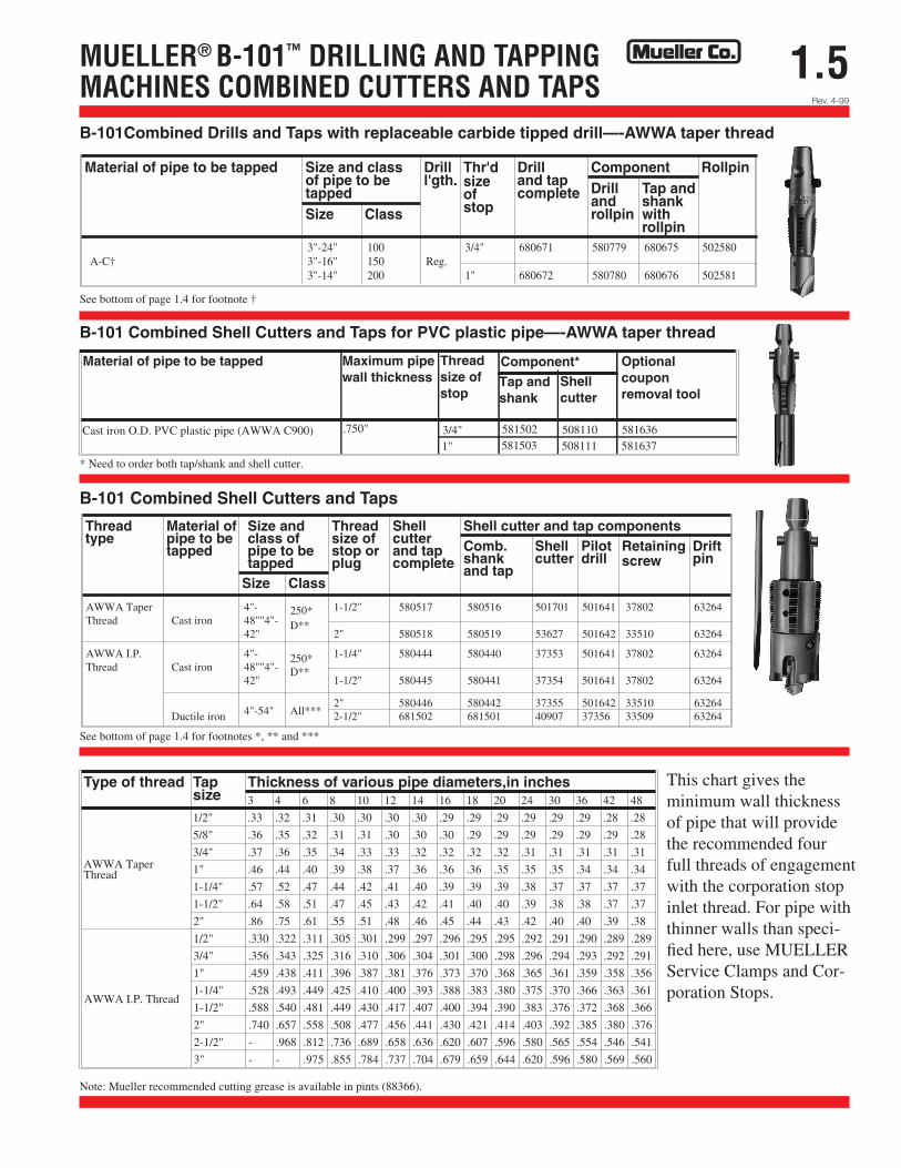
1.5MUELLER® B-101™ DRILLING AND TAPPINGMACHINES COMBINED CUTTERS AND TAPS
B-101Combined Drills and Taps with replaceable carbide tipped drill—-AWWA taperMaterial of pipe to be tapped Size and class
of pipe to betapped
Drilll'gth.
Thr'dsizeofstop
Drilland tapcomplete
Component RollpinDrillandrollpin
Tap andshankwithrollpin
Size Class
See bottom of page 1.4 for footnote †
3"-24" 100 3/4" 680671 580779 680675 502580A-C† 3"-16" 150 Reg.
3"-14" 200 1" 680672 580780 680676 502581
B-101 Combined Shell Cutters and Taps for PVC plastic pipe – AWWA taperMaterial of pipe to be tapped Maximum pipe
wall thicknessThreadsize of stop
Component*
Tap andshank
Shellcutter
Optional coupon removal tool
Cast iron O.D. PVC plastic pipe (AWWA C900) .750" 3/4"1"
581502581503
508110508111
581636581637
Type of thread Tapsize
Thickness of various pipe diameters,in inches3 4 6 8 10 12 14 16 18 20 24 30 36 42 48
AWWA TaperThread
1/2" .33 .32 .31 .30 .30 .30 .30 .29 .29 .29 .29 .29 .29 .28 .28
5/8" .36 .35 .32 .31 .31 .30 .30 .30 .29 .29 .29 .29 .29 .29 .28
3/4" .37 .36 .35 .34 .33 .33 .32 .32 .32 .32 .31 .31 .31 .31 .31
1" .46 .44 .40 .39 .38 .37 .36 .36 .36 .35 .35 .35 .34 .34 .34
1-1/4" .57 .52 .47 .44 .42 .41 .40 .39 .39 .39 .38 .37 .37 .37 .37
1-1/2" .64 .58 .51 .47 .45 .43 .42 .41 .40 .40 .39 .38 .38 .37 .37
2" .86 .75 .61 .55 .51 .48 .46 .45 .44 .43 .42 .40 .40 .39 .38
AWWA I.P. Thread
1/2" .330 .322 .311 .305 .301 .299 .297 .296 .295 .295 .292 .291 .290 .289 .289
3/4" .356 .343 .325 .316 .310 .306 .304 .301 .300 .298 .296 .294 .293 .292 .291
1" .459 .438 .411 .396 .387 .381 .376 .373 .370 .368 .365 .361 .359 .358 .356
1-1/4" .528 .493 .449 .425 .410 .400 .393 .388 .383 .380 .375 .370 .366 .363 .361
1-1/2" .588 .540 .481 .449 .430 .417 .407 .400 .394 .390 .383 .376 .372 .368 .366
2" .740 .657 .558 .508 .477 .456 .441 .430 .421 .414 .403 .392 .385 .380 .376
2-1/2" - .968 .812 .736 .689 .658 .636 .620 .607 .596 .580 .565 .554 .546 .541
3" - - .975 .855 .784 .737 .704 .679 .659 .644 .620 .596 .580 .569 .560
AWWA Taper 4"- 1-1/2" 580517 580516 501701 501641 37802 63264Thread Cast iron 48""4"-
250*
42"D**
2" 580518 580519 53627 501642 33510 63264
AWWA I.P. 4"- 1-1/4" 580444 580440 37353 501641 37802 63264Thread Cast iron 48""4"-
250*
42"D**
1-1/2" 580445 580441 37354 501641 37802 63264
2" 580446 580442 37355 501642 33510 63264Ductile iron 4"-54" All*** 2-1/2" 681502 681501 40907 37356 33509 63264
B-101 Combined Shell Cutters and Taps
Threadtype
Material ofpipe to betapped
Size andclass ofpipe to betapped
Threadsize ofstop orplug
Shellcutterand tapcomplete
Shell cutter and tap componentsComb.shankand tap
Shellcutter
Pilotdrill
Retainingscrew
Driftpin
Size Class
B-101Combined Drills and Taps with replaceable carbide tipped drill—-AWWA taper thread
See bottom of page 1.4 for footnote †
B-101 Combined Shell Cutters and Taps for PVC plastic pipe—-AWWA taper thread
* Need to order both tap/shank and shell cutter.
See bottom of page 1.4 for footnotes *, ** and ***
This chart gives the minimum wall thickness of pipe that will provide the recommended four full threads of engagement with the corporation stop inlet thread. For pipe with thinner walls than speci-fied here, use MUELLER Service Clamps and Cor-poration Stops.
Note: Mueller recommended cutting grease is available in pints (88366).
Rev. 4-99
1.4Rev. 9-09 Shaded area indicates change
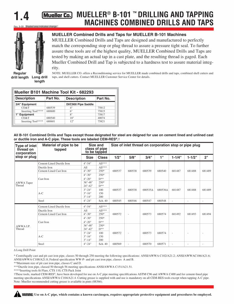
MUELLER® B-101 ™ DRILLING AND TAPPINGMACHINES COMBINED DRILLS AND TAPS
Cement-Lined Ductile Iron 4"-54" All***Ductile Iron All All***Cement-Lined Cast Iron 4"-30" 250* 680537 680538 680539 680540 681487 681488 681489
4"-30" 250*Cast Iron 4"-20" D**
36"-48" 250*24"-42" D**3"-24" 100 680537 680538 680535∆ 680536∆ 681487 681488 681489
A-C 3"-16" 1503"-14" 200
Steel 4"-24" Sch. 40 680545 680546 680547 680548 - - -
Cement-Lined Ductile Iron 4"-54" All***Ductile Iron All All***Cement-Lined Cast Iron 4"-30" 250* 680572 - 680573 680574 681492 681493 681494
4"-30" 250*Cast Iron 4"-20" D**
36"-48" 250*24"-42" D**3"-24" 100 680572 - 680573 680574 - - -
A-C 3"-16" 1503"-14" 200
Steel 4"-24" Sch. 40 680569 - 680570 680571 - - -
Type of inletthread on
corporationstop or plug
Material of pipe to betapped
Size andclass of pipeto be tapped
Size of inlet thread on corporation stop or pipe plug
Size Class 1/2" 5/8" 3/4" 1" 1-1/4" 1-1/2" 2"
AWWA TaperThread
AWWA I.P.Thread
∆ Long Drill Point
MUELLER Combined Drills and Taps for MUELLER B-101 Machines MUELLER Combined Drills and Taps are designed and manufactured to perfectly match the corresponding stop or plug thread to assure a pressure tight seal. To further assure these tools are of the highest quality, MUELLER Combined Drills and Taps are tested by making an actual tap in a cast plate, and the resulting thread is gaged. Each Mueller Combined Drill and Tap is subjected to a hardness test to assure material integ-rity. NOTE: MUELLER CO. offers a Reconditioning service for MUELLER made combined drills and taps, combined shell cutters and taps, and shell cutters. Contact MUELLER Customer Service Center for details.
All B-101 Combined Drills and Taps except those deignated for steel are deigned for use on cement lined and unlined cast or ductile iron and A-C pipe. These tools are labeled CEM-RES®.†
Regular drill length Long drill
length
* Centrifugally cast and pit cast iron pipe, classes 50 through 250 meeting the following specifications: ANSI/AWWA C102/A21.2; ANSI/AWWAC106/A21.6; ANSI/AWWA C108/A21.8; Federal specification WW-P- and pit cast iron pipe, classes A and B. **Maximum size of pit cast iron pipe, classes C and D. ***Ductile iron pipe, classed 50 through 56 meeting specifications ANSI/AWWA C151/A21.51. ****Inserting tools fit Flare, CTS 110, CTS Pack Joint †These tools, marked CEM-RES®, have been developed for use on A-C pipe meeting specififcations ASTM C96 and AWWA C400 and for cement-lined pipe meeting specifications ANSI/AWWA C104/A21.4. Cutting grease is supplied with and use is mandatory on all CEM-RES tools except when tapping A-C pipe. Note: Mueller recommended cutting grease is available in pints (88366).
Mueller B101 Machine Tool Kit - 682293Description Part No.
3/4" Equipment DI/C900 Pipe Saddle CD&T 680539 4" 75812 Inserting Tool**** 680600 6" 758151" Equipment 8" 75817 CD&T 680540 10" 40074 Inserting Tool**** 680601 12" 75821
Description Part No.
WARNING: Use on A-C pipe, which contains a known carcinogen, requires appropriate protective equipment and procedures be employed.
Rev. 9-09
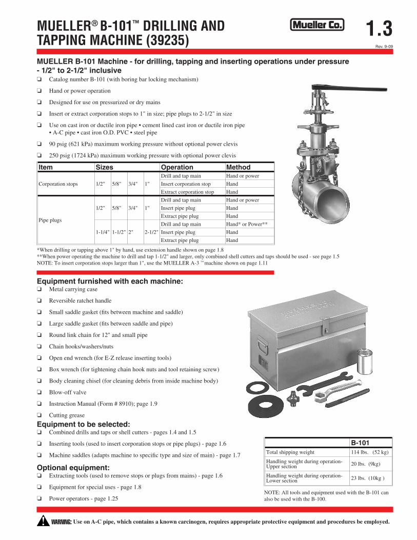
1.3MUELLER® B-101™ DRILLING AND TAPPING MACHINE (39235)
Item Sizes Operation Method
Corporation stops 1/2" 5/8" 3/4" 1"
Drill and tap main Hand or power
Insert corporation stop Hand
Extract corporation stop Hand
Pipe plugs
1/2" 5/8" 3/4" 1"
Drill and tap main Hand or power
Insert pipe plug Hand
Extract pipe plug Hand
1-1/4" 1-1/2" 2" 2-1/2"
Drill and tap main Hand* or Power**
Insert pipe plug Hand
Extract pipe plug Hand
B-101Total shipping weight 114 lbs. (52 kg)
Handling weight during operation-Upper section 20 lbs. (9kg)
Handling weight during operation-Lower section 23 lbs. (10kg )
MUELLER B-101 Machine - for drilling, tapping and inserting operations under pressure - 1/2" to 2-1/2" inclusive o Catalog number B-101 (with boring bar locking mechanism)
o Hand or power operation
o Designed for use on pressurized or dry mains
o Insert or extract corporation stops to 1" in size; pipe plugs to 2-1/2" in size
o Use on cast iron or ductile iron pipe • cement lined cast iron or ductile iron pipe • A-C pipe • cast iron O.D. PVC • steel pipe
o 90 psig (621 kPa) maximum working pressure without optional power clevis
o 250 psig (1724 kPa) maximum working pressure with optional power clevis
*When drilling or tapping above 1" by hand, use extension handle shown on page 1.8 **When power operating the machine to drill and tap 1-1/2" and larger, only combined shell cutters and taps should be used - see page 1.5 NOTE: To insert corporation stops larger than 1", use the MUELLER A-3 ™ machine shown on page 1.11
Equipment furnished with each machine: o Metal carrying case
o Reversible ratchet handle
o Small saddle gasket (fits between machine and saddle)
o Large saddle gasket (fits between saddle and pipe)
o Round link chain for 12" and small pipe
o Chain hooks/washers/nuts
o Open end wrench (for E-Z release inserting tools)
o Box wrench (for tightening chain hook nuts and tool retaining screw)
o Body cleaning chisel (for cleaning debris from inside machine body)
o Blow-off valve
o Instruction Manual (Form # 8910); page 1.9
o Cutting grease
Equipment to be selected: o Combined drills and taps or shell cutters - pages 1.4 and 1.5
o Inserting tools (used to insert corporation stops or pipe plugs) - page 1.6
o Machine saddles (adapts machine to specific type and size of main) - page 1.7
Optional equipment: o Extracting tools (used to remove stops or plugs from mains) - page 1.6
o Equipment for special uses - page 1.8
o Power operators - page 1.25 NOTE: All tools and equipment used with the B-101 can also be used with the B-100.
WARNING: Use on A-C pipe, which contains a known carcinogen, requires appropriate protective equipment and procedures be employed.