drilling, tapping & threading · the drilling, tapping & threading . self instruction...
TRANSCRIPT
DRILLING, TAPPING &
THREADING (DTT)
Learner Guide

TABLE OF CONTENTS
INTRODUCTION PAGE 1 PROGRESS SUMMARY - PRACTICAL TASKS PAGE 3 DRILLING - DTT-1 SUMMARY NOTES PAGE 4 THEORETICAL EXERCISE PAGE 9 CRITERION TEST PART B PAGE 11 CRITERION TEST PART A PAGE 12 PRACTICAL EXERCISE PAGE 14 DRILL SHARPENING - DTT-2 SUMMARY NOTES PAGE 15 PRACTICAL EXERCISE PAGE 17 CRITERION TEST PAGE 18 HAND TAPPING - DTT-3 SUMMARY NOTES PAGE 19 PRACTICAL EXERCISE PAGE 22 CRITERION TEST PAGE 23 THREADING BY HAND - DTT-4 SUMMARY NOTES PAGE 24 PRACTICAL EXERCISE PAGE 30 CRITERION TEST PAGE 31
CONTACT DETAILS: https://techav.co.za
Back to Table of Contents 1
THE DRILLING, TAPPING & THREADING SELF INSTRUCTION PROGRAMME
INTRODUCTION This programme has been designed to provide you, the learner, with the necessary basic information to perform essential metal work skills. Your primary source of information is a video programme. The video shows you what you need to know. Together with this workbook, your Course Controller and the video programmes you will receive enough input to enable you to: i) Drill holes, accurately and safely, into metal work pieces. ii) Produce well-formed threads in holes. iii) Produce well-formed threads onto round bars. However, what this programme cannot give you is EXPERIENCE! This is something that only you can provide - through PRACTICE. HOW TO USE THIS MATERIAL 1. Read through this workbook. 2. Watch each video programme to see how things are done. 3. Practice the procedures demonstrated in the videos. This workbook contains certain
exercises, some theoretical, some practical. All questions are based on a "must know" or "should know" principle. Answer the questions firstly in pencil, then, have your Course Controller check and correct your answers. Thereafter write them in ink. Keep this workbook as reference for the future.
4. Your Course Controller will allocate relevant work exercises according to the type of work and the conditions existing in your place of work or your training-centre. Remember! - Your Course Controller is there to help you. If you do not understand something or if you need assistance, ASK.
5. When you think you have had enough practice and have learned the material thoroughly, then ask for the CRITERION TEST. The criterion test is performed by you, without assistance and is based upon whether you can perform the tasks demonstrated. There are NO tricks to the criterion test - you are simply marked on your ability to perform the work and supply relevant information.
6. Have your Course Controller update your progress summary as you complete each task. SUMMARY OF LEARNING PROCEDURE 1. Read through this workbook. 2. View each video, beginning with DTT-1. 3. Re-view each section of video. Stop when you see a "discussion logo" or "practical
logo". 4. Switch off the video during discussion or practical breaks and perform the suggested
exercise, or that task given by your Course Controller. 5. Practice each task demonstrated at your own workbench.

Back to Table of Contents 2
6. Perform a criterion test - given to you by your Course Controller. FURTHER STUDY MATERIAL 1. Study the SOMTA users guide for drills and taps. 2. Study SOMTA wall charts on drills and taps.
A THOUGHT
Give instruction to a wise man and he will be yet wiser. Proverbs 9:9
Back to Table of Contents 3
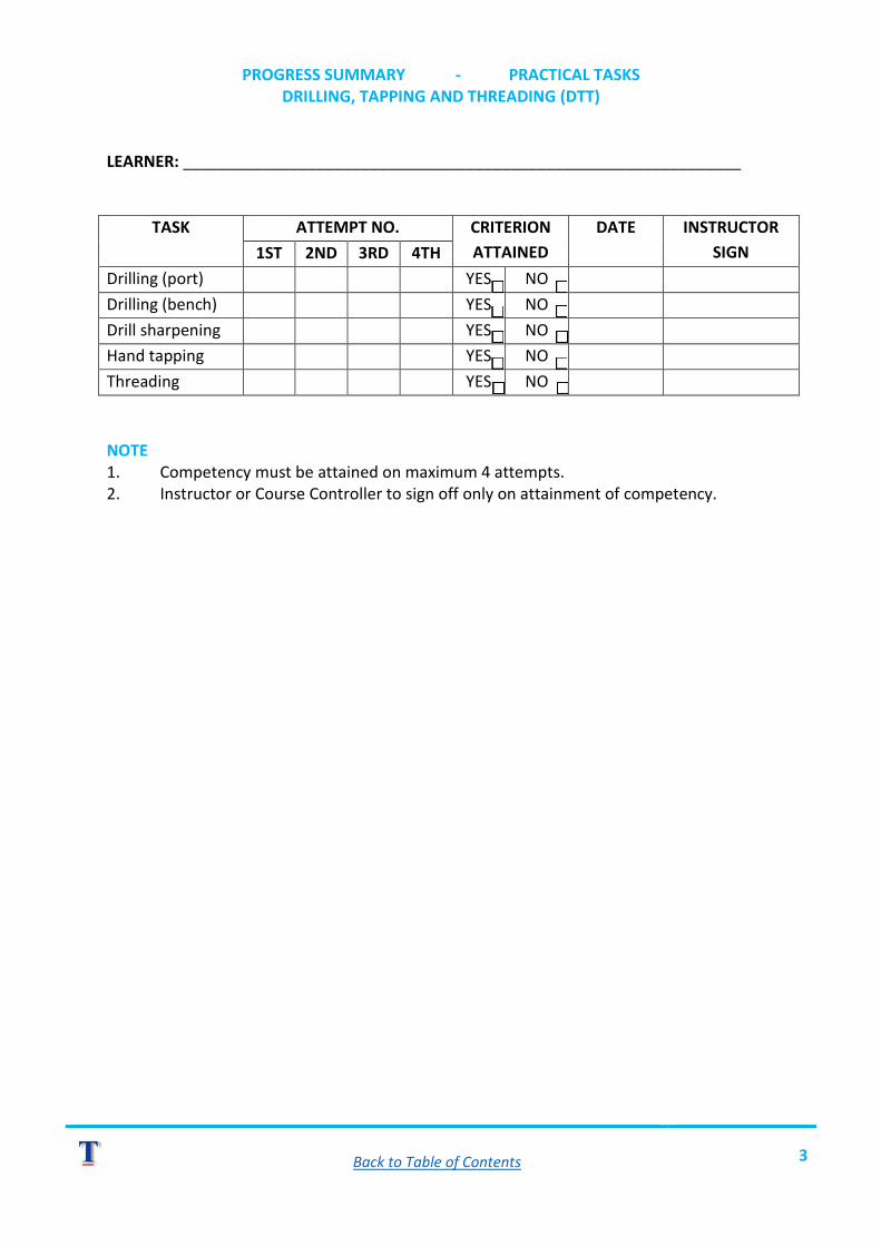
PROGRESS SUMMARY - PRACTICAL TASKS DRILLING, TAPPING AND THREADING (DTT)
LEARNER: _______________________________________________________________
TASK ATTEMPT NO. CRITERION ATTAINED
DATE INSTRUCTOR SIGN 1ST 2ND 3RD 4TH
Drilling (port) YES NO Drilling (bench) YES NO Drill sharpening YES NO Hand tapping YES NO Threading YES NO NOTE 1. Competency must be attained on maximum 4 attempts. 2. Instructor or Course Controller to sign off only on attainment of competency.
Back to Table of Contents 4
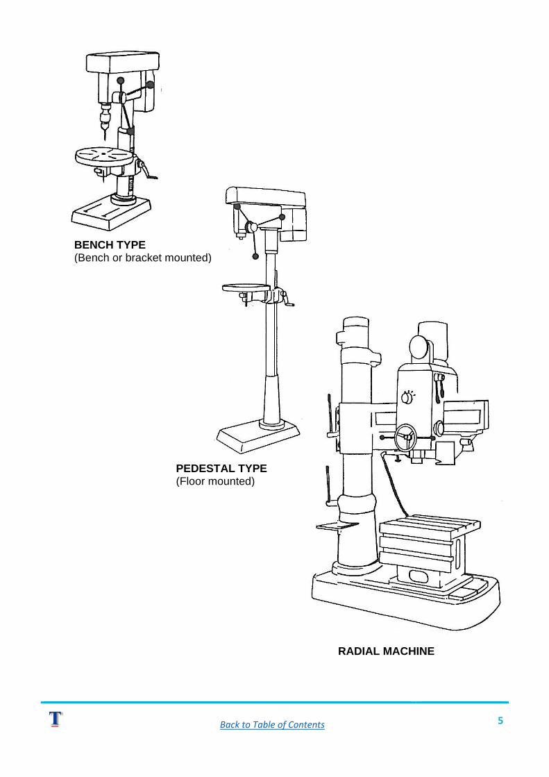
DRILLING, TAPPING AND TREADING PART ONE: - DRILLING (SUMMARY NOTES) Reference Material: - Video DTT-1. - SOMTA User Guide - "Drills, Reamers, Taps". - The operator's manual for your bench and portable drilling machines. AN OVERVIEW The primary purpose of drilling is to produce a hole in a given material. To produce holes in metal we need the assistance of: 1. A twist drill. 2. A drilling machine. TWIST DRILLS There are several types of twist drills each designed for a specific purpose. For an explicit overview of types read pages 7 - 11 in the SOMTA User Guide (Drills, reamers & taps). The drills used in the demonstrations (re: video programmes) are of the "general purpose, high speed steel" (H.S.S.) types. DRILLING MACHINES Nowadays most metal work drilling is performed using an electrically powered machine of one kind or another. The video programme demonstrates a "portable machine" often referred to as a "hand-machine" and a "fixed machine". A fixed machine cannot be moved around and is bolted to a bench or to the floor. The Radial type machine is not within the scope of this programme but will be covered in more advanced "machine-skills" productions.
Back to Table of Contents 5
BENCH TYPE (Bench or bracket mounted)
PEDESTAL TYPE (Floor mounted)
RADIAL MACHINE
Back to Table of Contents 6
TYPICAL FIXED TYPE DRILLING MACHINES. PRACTICAL USAGE OF DRILLING MACHINES A. PORTABLE TYPES: - Key points to remember. 1. Only use the "hammer action" when drilling into masonry. 2. Perform a safety check before using. 3. Return a faulty machine to your stores for attention by a qualified electrician. 4. Always protect your eyes - wear safety-goggles. 5. Ensure that cables (extensions etc.) do not layover walkways, vehicle accesses or sharp edges. 6. Never work in wet conditions. 7. Wear proper shoes - with rubber or insulated sales. 8. Carry the machine by its body, not by the power cord. 9. Make a centre-punch mark at the centre of the drilling position - this will prevent the drill from running-off. 10. Fit the drill into the chuck in such a way that the shank only is gripped. Approximately ⅓ of the shank should be visible when the drill is properly installed. 11. Check that the drill runs true i.e. it does not wobble. 12. Select the correct speed - Slow for large drills (7 - 13 mm). - Fast for small drills (0,5 - 6 mm).
13. Keep the drill at 90⁰ to the work surface. 14. Use the support handle on larger machines to ensure that the machine does not twist out of your hands should the drill snag.
15. Maintain enough pressure to keep the drill cutting. Ease up on the pressure and keep a firm grip on the machine as the point breaks through the material.
16. Allow the drill to cool before removing it. B. FIXED TYPES: - Key points to remember. As fixed machines have several features we shall break the operations down - into the key areas. 1. INSTALLATION OF MORSE TAPER DRILL
o Ensure selected drill is clean and dry. o Ensure that the female taper in the spindle is clean and dry. o Insert shank into the spindle taper, twist it until you feel the flat
"tang" engage the location slot within the sleeve. o Secure the drill by pulling down the operating handle and pressing the
point onto a piece of timber. 2. INSTALLATION OF STRAIGHT SHANK DRILLS (Parallel shank)
o Firstly install the chuck into the spindle in the same manner as installing a taper shank.
Back to Table of Contents 7
o Select drill to be used and check drill point for damage and shank for scoring.
o Install the drill in such a way that the shank only is gripped. Check that ⅓ of the shank length is visible below the chuck jaws.
o Secure the drill firmly -then remove the chuck key. o If the drill does not run true -remove it and check if the shank is
scored or the drill is bent (if a small size). 3. SETTING UP THE WORKPIECE (into a machine vice)
o Ensure the vice is clean and free of metal shavings (swarf). o Lower (or raise) the table to provide clearance below the drill. o If you are to drill an open/through hole then place a suitable sized
piece of flat timber into the vice to sit below the work piece. o Place the work piece into the vice and secure it. o Level the work piece either with a spirit level or by squaring it against
the drill, using an engineer's square. NB.: On tilting table models ensure that the table is set to 0 (zero).
o Secure the work piece firmly once it has been levelled. o Raise the table to bring the work piece surface a few millimetres
below the point of the drill. o Manoeuvre the table, or the vice, or both, until the drill aligns exactly
onto the centre punch mark (pull down operating handle to establish this).
o Firmly secure all locks and vice mountings. 4. SETTING SPEEDS AND DEPTH CONTROL
o If material is to be drilled through bring point down to contact work piece then set the depth control to approximately 5 mm more than material thickness.
o On blind holes, set depth to specified amount. o With the aid of a chart establish the drill rotational speed with
consideration to: a) The type of material being drilled. b) The diameter of the drill. c) The type of drill. (e.g. H.S.S.) (Refer to SOMTA User Guide - Drills, Reamers, Taps pages 12 - 17)
o Set the appropriate spindle speed on your machine according to the operator's manual.
Safety Notes: On belt/pulley drive models always ISOLATE THE POWER SUPPLY before effecting belt position changes. 5. DRILLING OPERATION
o Wear suitable eye protection.
Back to Table of Contents 8
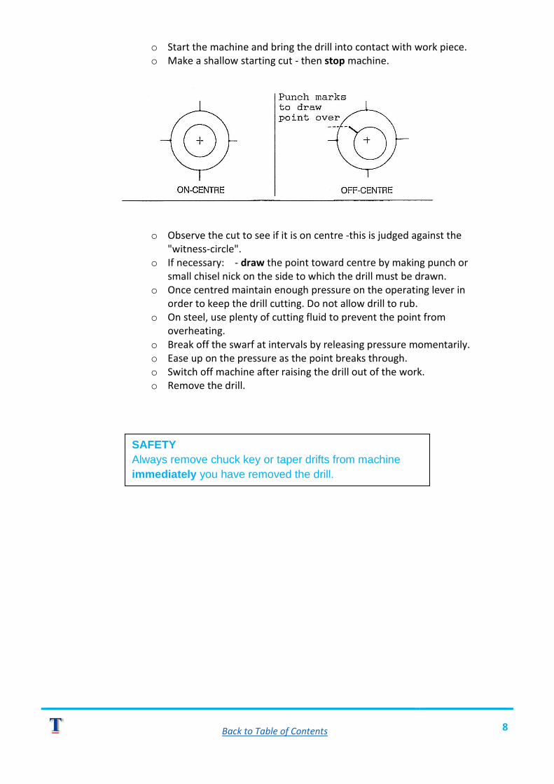
o Start the machine and bring the drill into contact with work piece. o Make a shallow starting cut - then stop machine.
o Observe the cut to see if it is on centre -this is judged against the "witness-circle".
o If necessary: - draw the point toward centre by making punch or small chisel nick on the side to which the drill must be drawn.
o Once centred maintain enough pressure on the operating lever in order to keep the drill cutting. Do not allow drill to rub.
o On steel, use plenty of cutting fluid to prevent the point from overheating.
o Break off the swarf at intervals by releasing pressure momentarily. o Ease up on the pressure as the point breaks through. o Switch off machine after raising the drill out of the work. o Remove the drill.
SAFETY Always remove chuck key or taper drifts from machine immediately you have removed the drill.

Back to Table of Contents 9
THEORETICAL EXERCISE DTT-1 DRILLING
Answer the following questions without reference to your notes - check your answers afterwards. 1. List all the relevant aspects of SAFETY that must be considered and obeyed when using Portable electric drilling machines. ___________________________________________________________________ ___________________________________________________________________ ___________________________________________________________________ ___________________________________________________________________ ___________________________________________________________________ ___________________________________________________________________ ___________________________________________________________________ ___________________________________________________________________ ___________________________________________________________________ 2. Describe how to fit a parallel (straight) shank bit into a chuck. 1. _________________________________________________________________ 2. _________________________________________________________________ 3. _________________________________________________________________ 4. _________________________________________________________________ 3. Describe how to fit a Morse Taper Shank bit to the fixed machine. 1. _________________________________________________________________ 2. _________________________________________________________________ 3. _________________________________________________________________ 4. What very important safety rule applies when you want to change belt positions on bench machine? ___________________________________________________________________ ___________________________________________________________________ 5. During the drilling operation you should be wearing what? ___________________________________________________________________ ___________________________________________________________________ 6. After removal of a bit from a machine what must you always do? ___________________________________________________________________ ___________________________________________________________________

Back to Table of Contents 10
SELF CHECK
Q1. Total no. correct out of 9 =
Q2. Total no. correct out of 4 =
Q3. Total no. correct out of 3 =
Q4. Tick right or wrong R W
Q5. Tick right or wrong R W
Q6. Tick right or wrong R W

Back to Table of Contents 11
CRITERION TEST DTT-1 - PART B
TASK - PRODUCE ACCURATE HOLES IN MILD STEEL HORKPIECE WITH A BENCH OR PEDESTAL DRILLING MACHINE. INSTRUCTIONS 1. Obtain stock material for drilling from your Instructor or Course Controller. 2. Mark out and drill holes as per sketch below.
MATERIAL: 10mm STOCK M/S
HAVE YOUR COURSE CONTROLLER ASSESS YOUR WORK.
Back to Table of Contents 12
CRITERION TEST DTT-1 - PART A
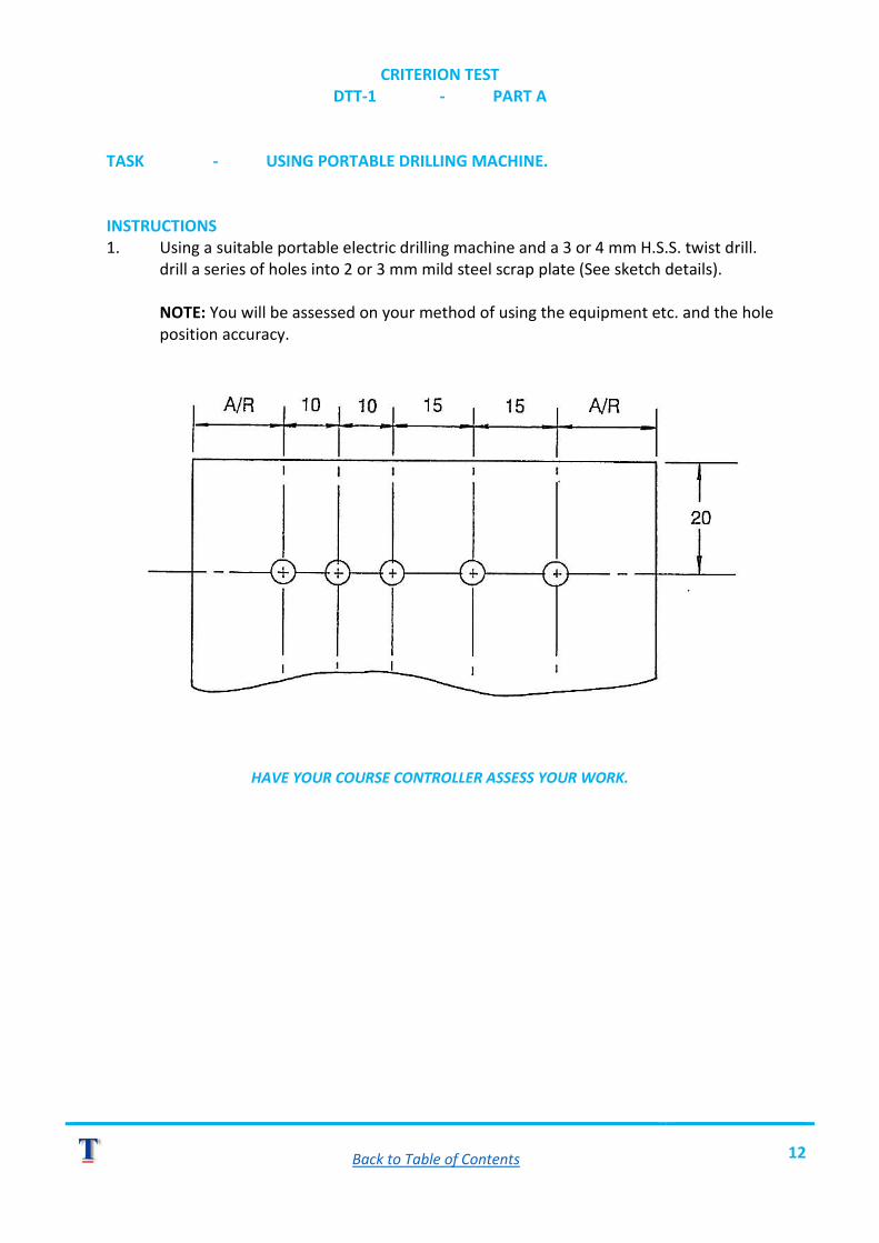
TASK - USING PORTABLE DRILLING MACHINE. INSTRUCTIONS 1. Using a suitable portable electric drilling machine and a 3 or 4 mm H.S.S. twist drill. drill a series of holes into 2 or 3 mm mild steel scrap plate (See sketch details). NOTE: You will be assessed on your method of using the equipment etc. and the hole position accuracy.
HAVE YOUR COURSE CONTROLLER ASSESS YOUR WORK.
Back to Table of Contents 13
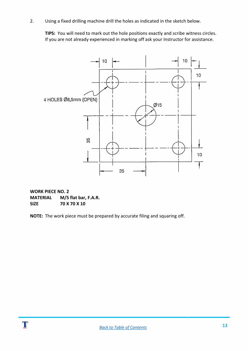
2. Using a fixed drilling machine drill the holes as indicated in the sketch below. TIPS: You will need to mark out the hole positions exactly and scribe witness circles. If you are not already experienced in marking off ask your Instructor for assistance.
WORK PIECE NO. 2 MATERIAL M/S flat bar, F.A.R. SIZE 70 X 70 X 10 NOTE: The work piece must be prepared by accurate filing and squaring off.
Back to Table of Contents 14
PRACTICAL EXERCISE DTT-1 - DRILLING
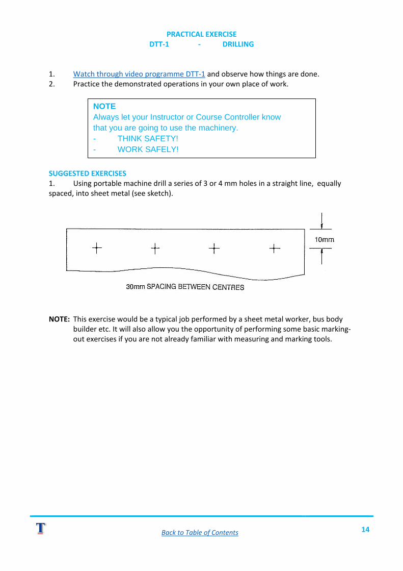
1. Watch through video programme DTT-1 and observe how things are done. 2. Practice the demonstrated operations in your own place of work. SUGGESTED EXERCISES 1. Using portable machine drill a series of 3 or 4 mm holes in a straight line, equally spaced, into sheet metal (see sketch).
NOTE: This exercise would be a typical job performed by a sheet metal worker, bus body builder etc. It will also allow you the opportunity of performing some basic marking- out exercises if you are not already familiar with measuring and marking tools.
NOTE Always let your Instructor or Course Controller know that you are going to use the machinery. - THINK SAFETY! - WORK SAFELY!
Back to Table of Contents 15
DRILLING, TAPPING AND THREADING PART 2 - DRILL SHARPENING (SUMMARY NOTES) Reference material - Video DTT-2. - SOMTA User Guide "Drills, reamers, tapes". AN OVERVIEW As with any "cutting-tool" a drill point will need occasional re-grinding in order that it be able to do its job properly. Although modern equipment enables drill points to be ground very professionally by formerly inexperienced people, there is still the need for you to learn how to perform the job by hand. We call this the "off-hand" method of drill sharpening. TERMINOLOGY (NOMENCLATURE) Study pages 6 and 7 of the SOMTA User Guide to learn the various parts and names of twist drills. TOOLS/EQUIPMENT REQUIRED To perform the job of drill point grinding you will require: 1. A bench or small pedestal grinding machine fitted with medium and fine grit grinding wheels of aluminium oxide type (see Tech, A,V, programme on Bench Grinding Machines). 2. A tray or container for cooling water. 3. A drill point gauge -(118°, graduated in mm). 4. An engineer's square (± 100 mm blade) or 5. A protractor gauge. 6. Safety goggles. PROCEDURE FOR TIP DRESSING As with most skills you can only be assured of producing good work after you have had enough practice. The following points should be kept in mind as you re-grind the drills. 1. Hake sure you have your goggles on! 2. Hake sure the wheel has been pr6perly dressed. 3. Support the drill firmly, resting it between the fingers of one hand which in turn is supported against the tool-rest. 4. Bring the point against the face of the wheel and ensure the cutting lip is flat or true to the grinding wheel surface. 5. Have the point in such a way that you follow the point profile as you grind the flank. 6. Cool the point frequently to avoid overheating and subsequent softening of the metal. 7. Use only light pressure against the wheel. 8. Grind both flanks in similar fashion.
Back to Table of Contents 16
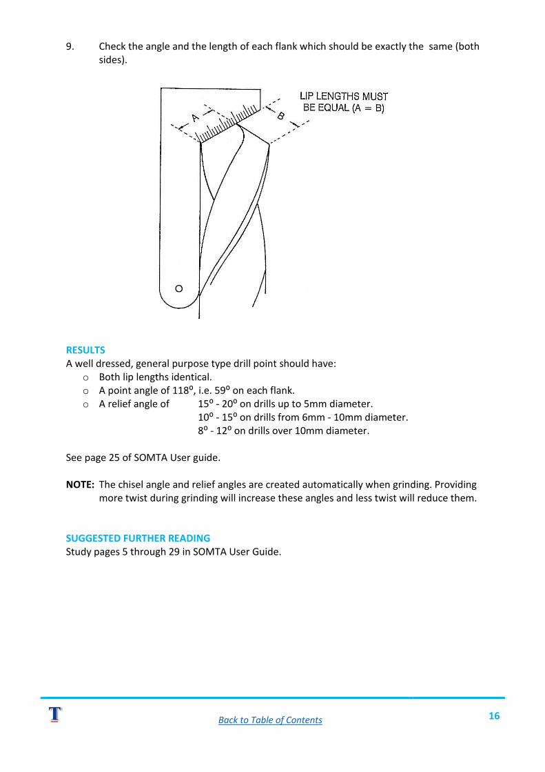
9. Check the angle and the length of each flank which should be exactly the same (both sides).
RESULTS A well dressed, general purpose type drill point should have:
o Both lip lengths identical. o A point angle of 118⁰, i.e. 59⁰ on each flank. o A relief angle of 15⁰ - 20⁰ on drills up to 5mm diameter.
10⁰ - 15⁰ on drills from 6mm - 10mm diameter. 8⁰ - 12⁰ on drills over 10mm diameter.
See page 25 of SOMTA User guide. NOTE: The chisel angle and relief angles are created automatically when grinding. Providing more twist during grinding will increase these angles and less twist will reduce them. SUGGESTED FURTHER READING Study pages 5 through 29 in SOMTA User Guide.
Back to Table of Contents 17
PRACTICAL EXERCISE DTT-2 - DRILLING SHARPENING
1. Watch the video programme right through DTT-2. 2. Practice the demonstrated operations in your own place of work. PRE-REQUISITE SKILL You should already be competent in the use of a bench type grinding machine. EXERCISE Obtain a variety of H.S.S. twist drills from your Course Controller and re-grind them according to the method demonstrated on the video programme. Begin with large drills as these are easier to work with and see.
NOTE Do not use any machinery unless you have been properly instructed. - THINK SAFETY! - WORK SAFELY!

Back to Table of Contents 18
CRITERION TEST DTT-2
TASK - DRILL BIT SHARPENING (DRESSING) INSTRUCTIONS 1. Ask your Instructor or Course Controller to provide you with a suitable H.S.S. drill that requires re-sharpening. 2. With the aid of a bench grinder sharpen the drill point to a standard point configuration.
HAVE YOUR COURSE CONTROLLER ASSESS YOUR WORK.
Back to Table of Contents 19
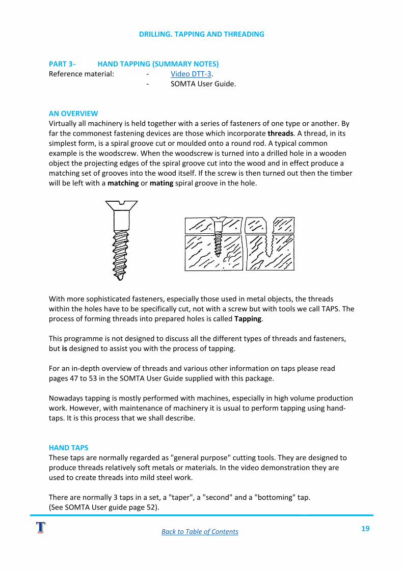
DRILLING. TAPPING AND THREADING PART 3 - HAND TAPPING (SUMMARY NOTES) Reference material: - Video DTT-3. - SOMTA User Guide. AN OVERVIEW Virtually all machinery is held together with a series of fasteners of one type or another. By far the commonest fastening devices are those which incorporate threads. A thread, in its simplest form, is a spiral groove cut or moulded onto a round rod. A typical common example is the woodscrew. When the woodscrew is turned into a drilled hole in a wooden object the projecting edges of the spiral groove cut into the wood and in effect produce a matching set of grooves into the wood itself. If the screw is then turned out then the timber will be left with a matching or mating spiral groove in the hole.
With more sophisticated fasteners, especially those used in metal objects, the threads within the holes have to be specifically cut, not with a screw but with tools we call TAPS. The process of forming threads into prepared holes is called Tapping. This programme is not designed to discuss all the different types of threads and fasteners, but is designed to assist you with the process of tapping. For an in-depth overview of threads and various other information on taps please read pages 47 to 53 in the SOMTA User Guide supplied with this package. Nowadays tapping is mostly performed with machines, especially in high volume production work. However, with maintenance of machinery it is usual to perform tapping using hand-taps. It is this process that we shall describe. HAND TAPS These taps are normally regarded as "general purpose" cutting tools. They are designed to produce threads relatively soft metals or materials. In the video demonstration they are used to create threads into mild steel work. There are normally 3 taps in a set, a "taper", a "second" and a "bottoming" tap. (See SOMTA User guide page 52).
Back to Table of Contents 20
TAPPING PROCEDURES STAGE 1 - MATERIAL/WORK PREPARATION i) Drilling positions are accurately marked out. ii) Holes are drilled. The diameter of the drill used must be of the correct size to accommodate the tap. i.e. tapping size. iii) Most SOMTA taps give the drill diameter size on the tap shank. The User Guide gives tables on pages 55 to 61 for various threads and the recommended tapping drill sizes. Alternatively the drill size can be calculated by subtracting the thread pitch from the tap diameter measured across the cutting lands. iv) Once drilled, the work piece is secured firmly, normally in a bench vice. STAGE 2 - TAPPING PROCEDURES i) Obtain the necessary tools:
o A set of taps with the specified thread size and type. o A tap-wrench of suitable size. o An engineer's square (± 100 mm blade). o Some sulphur based cutting paste if you are tapping steel.
ii) Apply a little cutting paste to each land of the taper tap and fit the tap to the tap-wrench. NOTE: Do not try to use a spanner to turn a tap as you will have no control over it). ii) Enter the tap into the hole, keep it upright and rotate it clockwise whilst maintaining a slight downward pressure. iv) Rotate by one turn only then remove the tap wrench and check the squareness of the tap. NOTE: Do not try to square this tap by striking it. v) If the tap is not square to the work then replace the tap-wrench and provide a slight pull toward the side which will bring it straight/upright, whilst at the same time twisting it in a clockwise motion for another half turn or so. Recheck for squareness. vi) Once squared up then proceed to slowly rotate the tap clockwise, allowing a half turn backward at frequent intervals in order to break off the swarf within the hole. NOTE: On brass or aluminium it is not necessary to turn the tap backward. vii) Continue tapping until: a) The tap end emerges through the hole. b) The tap "bottoms" in a blind hole. IMPORTANT: NEVER FORCE A TAP - IT WILL BREAK AND BE EXTREMELY DIFFICULT TO REMOVE. viii) Remove the tap by slowly turning it anti clockwise out of the hole. ix) Clean the tap and brush away the debris. (Blowout the debris from within a blind hole.) ON AN OPEN HOLE Run the "second" tap through, using cutting paste on steel. This will "finish" the threads.

Back to Table of Contents 21
ON A BLIND HOLE o Run the "bottoming" tap into the hole, carefully - using cutting paste on steel. o Carefully "feel" the cutting operation as you approach the bottom of the hole. Do
not over-strain the tap. o Provide frequent back turns when tapping harder materials to prevent clogging the
flutes and damaging the threads. o Remove the tap and blowout debris from time to time as it will otherwise prevent
the tap from bottoming fully. NOTE: To monitor the depth for blind-hole tapping, mark the depth of the hole to be tapped onto the tap with masking tape or koki pen.
Back to Table of Contents 22
PRACTICAL EXERCISE DTT-3 - HAND TAPPING
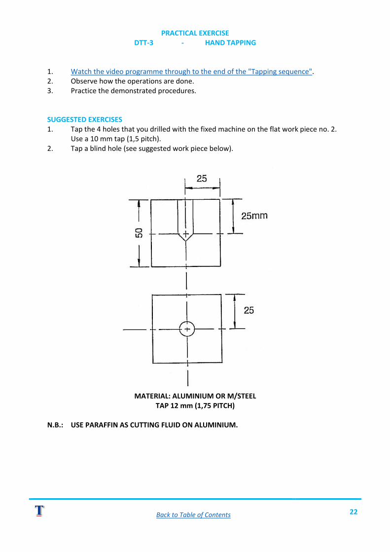
1. Watch the video programme through to the end of the "Tapping sequence". 2. Observe how the operations are done. 3. Practice the demonstrated procedures. SUGGESTED EXERCISES 1. Tap the 4 holes that you drilled with the fixed machine on the flat work piece no. 2. Use a 10 mm tap (1,5 pitch). 2. Tap a blind hole (see suggested work piece below).
MATERIAL: ALUMINIUM OR M/STEEL
TAP 12 mm (1,75 PITCH) N.B.: USE PARAFFIN AS CUTTING FLUID ON ALUMINIUM.

Back to Table of Contents 23
CRITERION TEST DTT-3
TASK - HAND TAPPING INSTRUCTIONS 1. Use the same work piece that you produced in criterion test no. 1B. 2. Tap each hole according to its size for METRIC COARSE PITCH.
HAVE YOUR COURSE CONTROLLER ASSESS YOUR WORK.

Back to Table of Contents 24
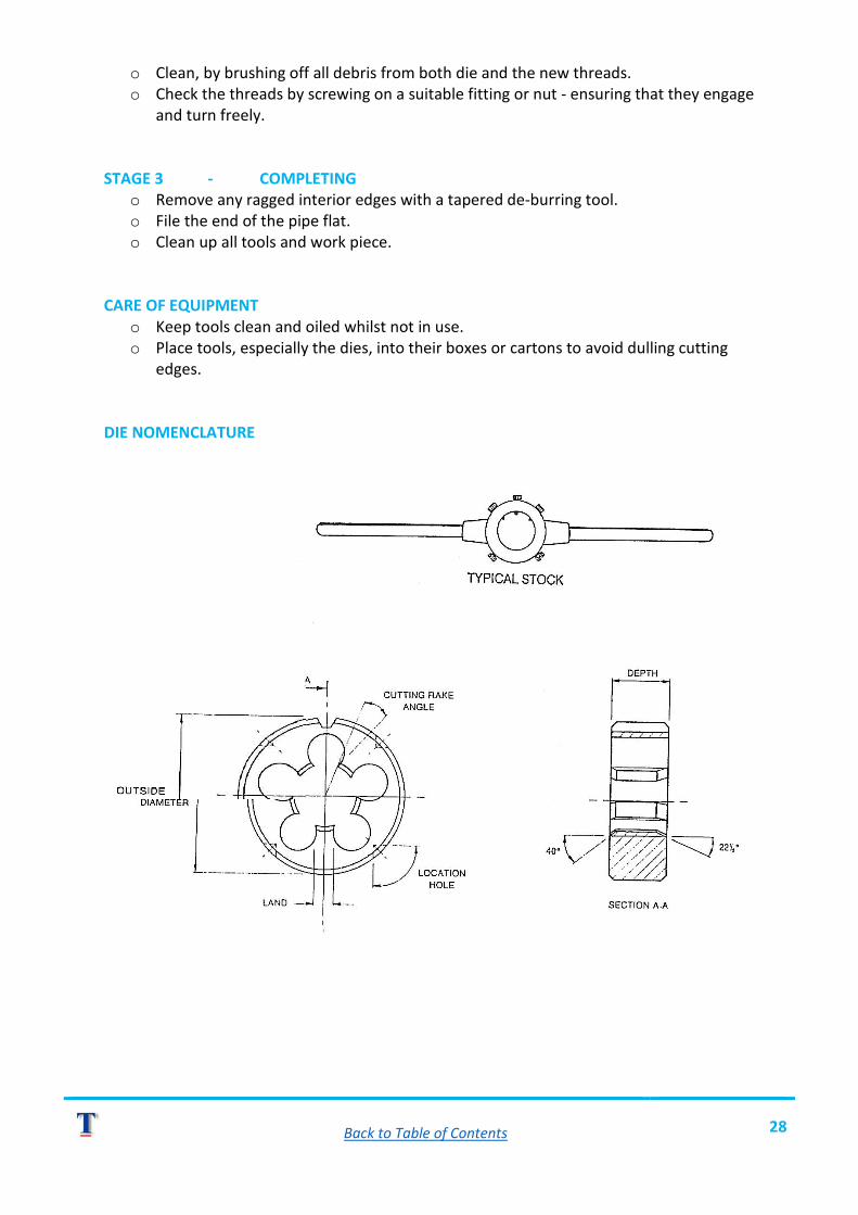
DRILLING, TAPPING AND THREADING PART FOUR: - THREADING BY HAND (SUMMARY NOTES) Reference material - Video DTT-4. AN OVERVIEW The practice of threading is required to produce the "counter thread" for the threads produced into holes or nuts. It is normal to refer to threads as being "male" and "female". A male thread fits into a female thread e.g. the holes you tapped in the previous exercise were female. The cutting of male threads is performed on round material, i.e., rods or shafts or tubes, and the tools principally used to make the threads are called "dies". There are several types of threading dies available, some suitable for hand operated procedures others specifically for machine operations. This programme deals with dies known as "split-type", sometimes referred to as "button-dies". Split-dies are used as "general purpose" cutting tools and are thus suitable for most materials, except hardened metal. Other dies demonstrated are pipe threading dies which, basically, are the same as split-dies. For purposes of "fine" finishing and for the restoration of damaged male threads a "die-nut" is utilised.
Back to Table of Contents 25
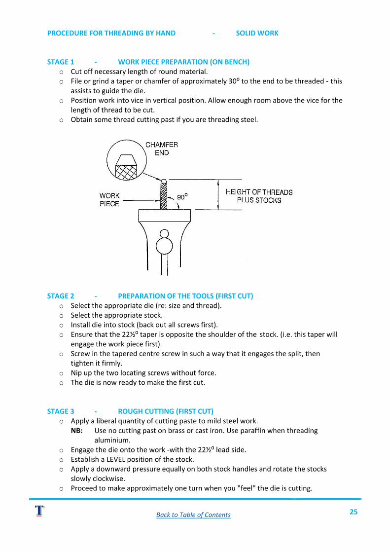
PROCEDURE FOR THREADING BY HAND - SOLID WORK STAGE 1 - WORK PIECE PREPARATION (ON BENCH)
o Cut off necessary length of round material. o File or grind a taper or chamfer of approximately 30⁰ to the end to be threaded - this
assists to guide the die. o Position work into vice in vertical position. Allow enough room above the vice for the
length of thread to be cut. o Obtain some thread cutting past if you are threading steel.
STAGE 2 - PREPARATION OF THE TOOLS (FIRST CUT)
o Select the appropriate die (re: size and thread). o Select the appropriate stock. o Install die into stock (back out all screws first). o Ensure that the 22½⁰ taper is opposite the shoulder of the stock. (i.e. this taper will
engage the work piece first). o Screw in the tapered centre screw in such a way that it engages the split, then
tighten it firmly. o Nip up the two locating screws without force. o The die is now ready to make the first cut.
STAGE 3 - ROUGH CUTTING (FIRST CUT)
o Apply a liberal quantity of cutting paste to mild steel work. NB: Use no cutting past on brass or cast iron. Use paraffin when threading aluminium.
o Engage the die onto the work -with the 22½⁰ lead side. o Establish a LEVEL position of the stock. o Apply a downward pressure equally on both stock handles and rotate the stocks
slowly clockwise. o Proceed to make approximately one turn when you "feel" the die is cutting.
Back to Table of Contents 26
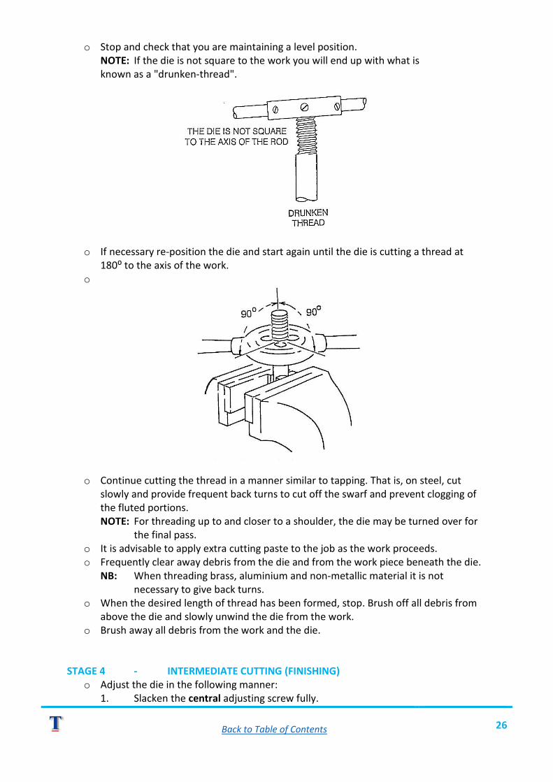
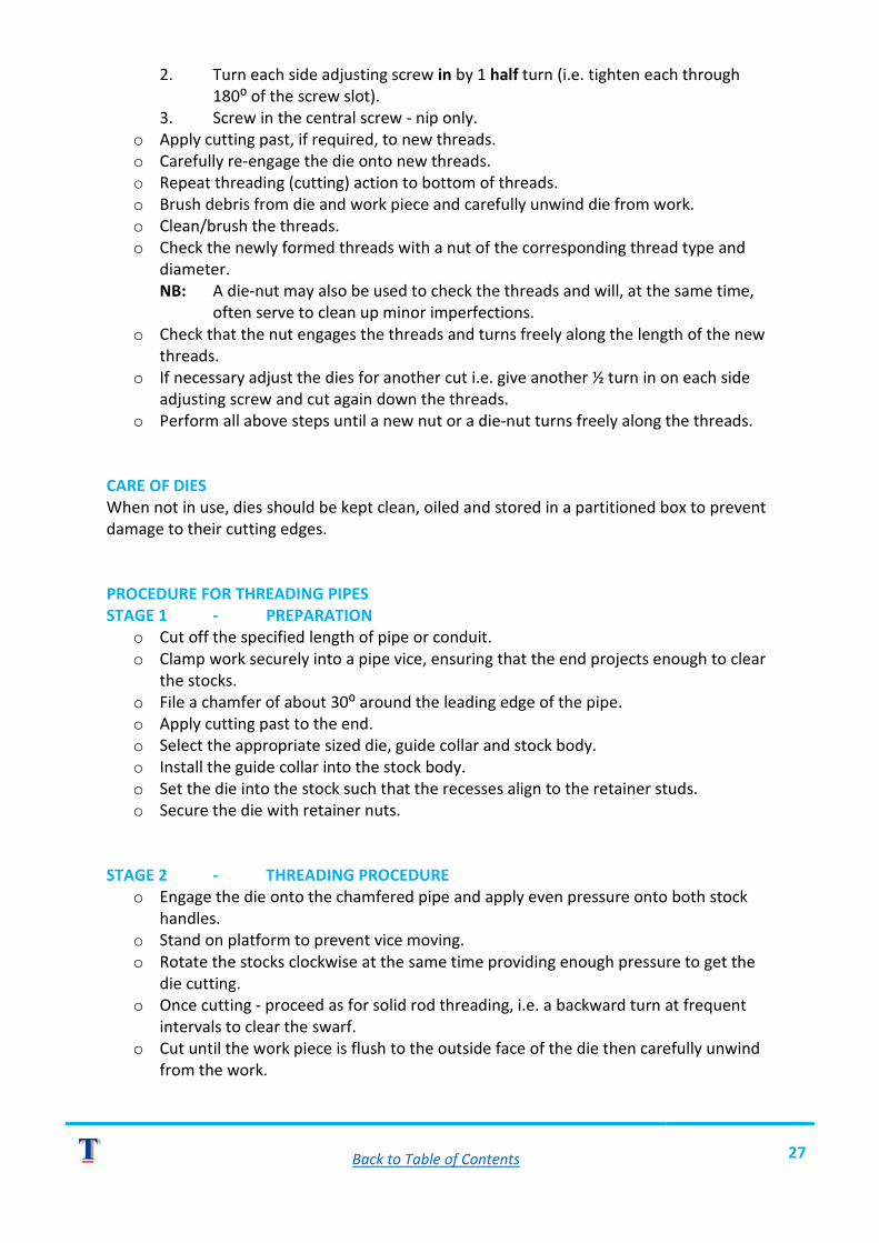
o Stop and check that you are maintaining a level position. NOTE: If the die is not square to the work you will end up with what is known as a "drunken-thread".
o If necessary re-position the die and start again until the die is cutting a thread at 180⁰ to the axis of the work.
o
o Continue cutting the thread in a manner similar to tapping. That is, on steel, cut slowly and provide frequent back turns to cut off the swarf and prevent clogging of the fluted portions.
NOTE: For threading up to and closer to a shoulder, the die may be turned over for the final pass.
o It is advisable to apply extra cutting paste to the job as the work proceeds. o Frequently clear away debris from the die and from the work piece beneath the die.
NB: When threading brass, aluminium and non-metallic material it is not necessary to give back turns.
o When the desired length of thread has been formed, stop. Brush off all debris from above the die and slowly unwind the die from the work.
o Brush away all debris from the work and the die.
STAGE 4 - INTERMEDIATE CUTTING (FINISHING) o Adjust the die in the following manner:
1. Slacken the central adjusting screw fully.
Back to Table of Contents 27
2. Turn each side adjusting screw in by 1 half turn (i.e. tighten each through 180⁰ of the screw slot). 3. Screw in the central screw - nip only.
o Apply cutting past, if required, to new threads. o Carefully re-engage the die onto new threads. o Repeat threading (cutting) action to bottom of threads. o Brush debris from die and work piece and carefully unwind die from work. o Clean/brush the threads. o Check the newly formed threads with a nut of the corresponding thread type and
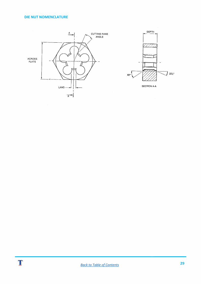
diameter. NB: A die-nut may also be used to check the threads and will, at the same time, often serve to clean up minor imperfections.
o Check that the nut engages the threads and turns freely along the length of the new threads.
o If necessary adjust the dies for another cut i.e. give another ½ turn in on each side adjusting screw and cut again down the threads.
o Perform all above steps until a new nut or a die-nut turns freely along the threads.
CARE OF DIES When not in use, dies should be kept clean, oiled and stored in a partitioned box to prevent damage to their cutting edges. PROCEDURE FOR THREADING PIPES STAGE 1 - PREPARATION
o Cut off the specified length of pipe or conduit. o Clamp work securely into a pipe vice, ensuring that the end projects enough to clear
the stocks. o File a chamfer of about 30⁰ around the leading edge of the pipe. o Apply cutting past to the end. o Select the appropriate sized die, guide collar and stock body. o Install the guide collar into the stock body. o Set the die into the stock such that the recesses align to the retainer studs. o Secure the die with retainer nuts.
STAGE 2 - THREADING PROCEDURE
o Engage the die onto the chamfered pipe and apply even pressure onto both stock handles.
o Stand on platform to prevent vice moving. o Rotate the stocks clockwise at the same time providing enough pressure to get the
die cutting. o Once cutting - proceed as for solid rod threading, i.e. a backward turn at frequent
intervals to clear the swarf. o Cut until the work piece is flush to the outside face of the die then carefully unwind
from the work.
Back to Table of Contents 28
o Clean, by brushing off all debris from both die and the new threads. o Check the threads by screwing on a suitable fitting or nut - ensuring that they engage
and turn freely. STAGE 3 - COMPLETING
o Remove any ragged interior edges with a tapered de-burring tool. o File the end of the pipe flat. o Clean up all tools and work piece.
CARE OF EQUIPMENT
o Keep tools clean and oiled whilst not in use. o Place tools, especially the dies, into their boxes or cartons to avoid dulling cutting
edges. DIE NOMENCLATURE
Back to Table of Contents 29
DIE NUT NOMENCLATURE

Back to Table of Contents 30
PRACTICAL EXERCISE DTT-4 - HAND THREADING
1. Watch the video programme through. 2. Observe how threading is performed. 3. Practice the demonstrated procedures. SUGGESTED EXERCISES 1. Obtain some stock round material e.g. 10 mm mild steel round bar and cut ± 30 mm length of thread onto it. 2. Thread the end of a piece of 20 mm electrical steel conduit or water pipe.
HAVE YOUR INSTRUCTOR CHECK YOUR WORK.
YOU ARE NOW READY TO PERFORM THE CRITERION TESTS.

Back to Table of Contents 31
CRITERION TEST DTT-4
TASK - ROD AND TUBE THREADING INSTRUCTIONS 1. Obtain a length of stock round-bar from your Instructor or Course Controller. 2. Obtain a length of 20 mm conduit (black steel). 3. Produce approximately 35 mm length of metric thread with a suitable die onto one end of the round-bar. 4. Produce a standard threaded end onto the conduit.
HAVE YOUR COURSE CONTROLLER ASSESS YOUR WORK.