operating instructions diesel...
TRANSCRIPT

Operating InstructionsDiesel engine18V2000Gx6x
MS15037/01E

Engine model kW/cyl. Application group18V2000G76S 76.2 kW/cyl. 3D; Standby power, fuel stop power, IFN
Table 1: Applicability
© 2018 Copyright MTU Friedrichshafen GmbH
This publication is protected by copyright and may not be used in any way, whether in whole or in part, without the prior writ-ten consent of MTU Friedrichshafen GmbH. This particularly applies to its reproduction, distribution, editing, translation, micro-filming and storage or processing in electronic systems including databases and online services.
All information in this publication was the latest information available at the time of going to print. MTU Friedrichshafen GmbHreserves the right to change, delete or supplement the information provided as and when required.

Table of Contents1 Safety
1.1 Important provisions for all products 51.2 Correct use of all products 71.3 Personnel and organizational requirements 81.4 Initial start-up and operation – Safety
regulations 91.5 Assembly, maintenance, and repair work –
Safety regulations 111.6 Fire and environmental protection, fluids
and lubricants 151.7 Standards for warning notices in the text
and highlighted information 17
2 Transport
2.1 Transport 18
3 General Information
3.1 Engine side and cylinder designations 193.2 Engine – Overview 20
4 Technical Data
4.1 Product data 18V2000G76S 214.2 Firing order 244.3 Engine – Main dimensions 25
5 Operation
5.1 Preparing startup after long out-of-serviceperiods (>3 months) 26
5.2 Preparations for startup after scheduled out-of-service-period 27
5.3 Engine – Starting 285.4 Re-starting the engine following an
automatic safety shutdown 295.5 Operational monitoring 305.6 Emission label – Check 315.7 Engine shutdown 325.8 Emergency engine shutdown 335.9 After stopping the engine 34
5.10 Plant – Cleaning 35
6 Maintenance
6.1 Maintenance task reference table [QL1] forEPA regions 36
7 Troubleshooting
7.1 Troubleshooting 377.2 Engine Control Unit – ECU9 fault messages 40
8 Task Description
8.1 Engine 688.1.1 Engine – Barring manually 688.1.2 Engine – Barring with starting system 698.1.3 Engine – Test run 70
8.2 Cylinder Liner 718.2.1 Cylinder liner – Endoscopic examination 718.2.2 Cylinder liner – Instructions and comments on
endoscopic and visual examination 73
8.3 Crankcase Breather 758.3.1 Crankcase breather – Oil mist separator
replacement 75
8.4 Fan Drive 768.4.1 Drive belt – Condition check 768.4.2 Drive belt – Tension check 778.4.3 Drive belt ‒ Tension adjustment 798.4.4 Drive belt – Replacement 80
8.5 Valve Drive 818.5.1 Valve clearance – Check and adjustment 818.5.2 Cylinder head cover – Cylinder head cover 83
8.6 Injection Valve / Injector 858.6.1 Injector ‒ Replacement 858.6.2 Injector – Removal and installation 868.6.3 Injector functions 91
8.7 Fuel System 928.7.1 HP fuel line and pressure pipe neck –
Replacement 928.7.2 Fuel system – Venting 948.7.3 Fuel – Draining 958.7.4 Fuel cooler – External contamination and leak-
tightness check 968.7.5 Fuel cooler – Cleaning 97
8.8 Fuel Filter 998.8.1 Fuel filter – Replacement 998.8.2 Fuel prefilter – Draining 1008.8.3 Fuel prefilter (non-switchable) – Draining 1018.8.4 Fuel prefilter (switchable) – Draining 1038.8.5 Fuel prefilter – Pressure ratios 1068.8.6 Fuel prefilter (switchable) – Low pressure
indicator check 1078.8.7 Fuel prefilter – Filter element replacement 1088.8.8 Fuel prefilter (non-switchable) – Filter element
replacement 1098.8.9 Fuel prefilter (switchable) – Filter element
replacement 111
MS15037/01E 2018-07 | Table of Contents | 3
DCL-
ID: 0
0000
4897
6 - 0
02

8.8.10 Fuel prefilter – Venting 114
8.9 Air Filter 1168.9.1 Air filter – Replacement 1168.9.2 Air filter – Removal and installation 117
8.10 Starting Equipment 1188.10.1 Electric starter ‒ Overview 1188.10.2 Starter – Removal 1198.10.3 Starter – Installation 1208.10.4 Pneumatic starter – Overview 1218.10.5 Starter – Removal 1228.10.6 Starter ‒ Installation 123
8.11 Air Intake 1248.11.1 Service indicator – Signal ring position check 124
8.12 Lube Oil System, Lube Oil Circuit 1258.12.1 Engine oil level – Check 1258.12.2 Engine oil – Change 126
8.13 Oil Filtration / Cooling 1278.13.1 Engine oil filter – Replacement 127
8.14 Coolant Circuit, General, High-TemperatureCircuit 1288.14.1 Drain and vent points 1288.14.2 Engine coolant – Level check 1328.14.3 Engine coolant – Change 1338.14.4 Engine coolant – Draining 1348.14.5 Engine coolant – Filling 1358.14.6 Engine coolant pump – Relief bore check 137
8.15 Coolant System 1388.15.1 Coolant cooler – External contamination and
leak-tightness check 1388.15.2 Coolant cooler – Cleaning 139
8.16 Battery-Charging Generator 1418.16.1 Drive belt – Condition check 1418.16.2 Drive belt – Tension check 1428.16.3 Drive belt ‒ Tension adjustment 1448.16.4 Drive belt – Replacement 145
8.17 Preheater 1468.17.1 Preheater – Overhaul 146
8.17.2 Preheater – Function and leak check 1478.17.3 Preheater – Heating element and housing
check 1488.17.4 Preheater – Heating element and housing
check 1518.17.5 Preheater – Heating element and housing
check 1548.17.6 Preheater – Solenoid switch replacement 1578.17.7 Preheater – Solenoid switch replacement 1598.17.8 Preheater – Solenoid switch replacement 1618.17.9 Preheater thermostats – Replacement 163
8.17.10 Preheater thermostats – Replacement 1668.17.11 Preheater thermostats – Replacement 169
8.18 Engine Mounting / Support 1728.18.1 Engine mounting – Checking securing screws
for firm seating 1728.18.2 Engine mounting – Checking condition of
resilient mounts 173
8.19 Generator 1748.19.1 Generator mounting – Checking condition of
resilient mounts 1748.19.2 Generator mounting – Checking firm seating
of securing screws 175
8.20 Engine Governor 1768.20.1 Engine Control Unit – Overview 1768.20.2 Engine Control Unit – Removal and
installation 1778.20.3 Engine governor plug connections – Check 178
8.21 Wiring (General) for Engine/Gearbox/Unit 1798.21.1 Engine cabling – Check 179
9 Appendix A
9.1 List of abbreviations 1809.2 MTU Contact/Service Partners 182
10 Appendix B
10.1 Index 18310.2 Special Tools 186
4 | Table of Contents | MS15037/01E 2018-07
DCL-
ID: 0
0000
4897
6 - 0
02
1 Safety
1.1 Important provisions for all products
GeneralThis product may pose a risk of injury or damage in the following cases:• Incorrect use• Operation, maintenance and repair by unqualified personnel• Changes or modifications which are neither made nor authorized by the manufacturer• Noncompliance with the safety instructions and warning notices
NameplatesThe product is identified by nameplate, model designation or serial number. This data must match the speci-fications in these instructions.
Nameplates, model designation or serial number can be found on the product.
All EU-certified engines delivered by MTU come with a second nameplate. This second nameplate is deliv-ered "loosely" with the engine. If the nameplate secured to the engine after installation in the vehicle/systemis not visible without the removal of components, the system integrator must install the second nameplate ina clearly visible area on the vehicle/system.
Emission specifications and emission label
Responsibility for compliance with emission regulationsModification or removal of any mechanical/electronic components or the installation of additional compo-nents including the execution of calibration processes that might affect the emission characteristics of theproduct are prohibited by emission regulations. Emission-related components must only be serviced, ex-changed or repaired if the components used for this purpose are approved by the manufacturer.
Noncompliance with these specifications will invalidate the design type approval or certification issued bythe emissions regulation authorities. The manufacturer does not accept any liability for violations of theemission regulations.
The product must be operated over its entire life cycle according to the conditions defined as "Intended use"(→ Page 7).
Emission certification applicable to engines with EPA Nonroad Tier 4 emissioncertification in accordance with 40 CFR 1039Extract from the standard:
Failing to follow these instructions when installing a certified engine in a piece of nonroad equipment violatesfederal law (40 CFR 1068.105(b)), subject to fines or other penalties as described in the Clean Air Act.
Extract from the standard:
If you install the engine in a way that makes the engine's emission control information label hard to readduring normal engine maintenance, you must place a duplicate label on the equipment, as described in 40CFR 1068.105.
When fitting the second label, the requirements of 40 CFR 1068.105(c) must be followed and observed. Thisparagraph describes the process for requesting and fitting the label, the documentation obligations and stor-age obligations for the required documents.
MS15037/01E 2018-07 | Safety | 5
TIM
-ID: 0
0000
4053
0 - 0
13
Replacing components with emission labelsOn all MTU engines fitted with emission labels, these labels must remain on the engine throughout its opera-tional life.
Exception: Engines used exclusively in land-based, military applications other than by US government agen-cies.
Please note the following when replacing components with emission labels:• The relevant emission labels must be affixed to the spare part.• Emission labels shall not be transferred from the replaced part to the spare part.• The emission labels must be removed from the replaced part and destroyed.
6 | Safety | MS15037/01E 2018-07
TIM
-ID: 0
0000
4053
0 - 0
13
1.2 Correct use of all products
Correct useThe product is intended for use in accordance with its contractually-defined purpose as described in the rele-vant technical documents only.
Intended use entails operation:• Within the permissible operating parameters in accordance with the (→ Technical data)• With fluids and lubricants approved by the manufacturer in accordance with the (→ Fluids and Lubricants
Specifications of the manufacturer)• With preservation approved by the manufacturer in accordance with the (→ Preservation and Represerva-
tion Specifications of the manufacturer)• With spare parts approved by the manufacturer in accordance with the (→ Spare Parts Catalog/MTU con-
tact/Service partner)• In the original as-delivered configuration or in a configuration approved by the manufacturer in writing (al-
so applies to engine control/parameters)• In compliance with all safety regulations and in adherence with all warning notices in this manual• In compliance with the maintenance work and intervals specified in the (→ Maintenance Schedule)
throughout the useful life of the product• In compliance with the maintenance and repair instructions contained in this manual, in particular with
regard to the specified tightening torques• With the exclusive use of technical personnel trained in commissioning, operation, maintenance and re-
pair
The product must not be operated in explosive atmospheres unless the engine fulfills the conditions for suchuse and approval has been granted.
Any other use, particularly misuse, is considered as being contrary to the intended purpose. Such improperuse increases the risk of injury and damage when working with the product. The manufacturer shall not beheld liable for any damage resulting from improper, non-intended use.
The specifications of the manufacturer will be amended or supplemented as necessary. Prior to operation,make sure that the latest version is used. The latest version can be found on the websites:• For drive systems: http://www.mtu-online.com• For power generation: http://www.mtuonsiteenergy.com
Modifications or conversionsUnauthorized changes to the product represent a contravention of its intended use and compromise safety.
Changes or modifications shall only be considered to comply with the intended use when expressly author-ized by the manufacturer. The manufacturer shall not be held liable for any damage resulting from unauthor-ized changes or modifications.
MS15037/01E 2018-07 | Safety | 7
TIM
-ID: 0
0000
6567
1 - 0
05

1.3 Personnel and organizational requirements
Organizational measures of the user/manufacturerThis manual must be issued to all personnel involved in operation, maintenance, repair, assembly, installa-tion, or transportation.
Keep this manual handy in the vicinity of the product such that it is accessible to operating, maintenance,repair, assembly, installation, and transport personnel at all times.
Personnel must receive instruction on product handling and repair based on this manual. In particular, per-sonnel must have read and understood the safety requirements and warnings before starting work.
This is important in the case of personnel who only occasionally perform work on or around the product.Such personnel must be instructed repeatedly.
Personnel requirementsAll work on the product must be carried out by trained, instructed and qualified personnel only:• Training at the Training Center of the manufacturer• Qualified personnel from the areas mechanical engineering, plant construction, and electrical engineering
and also for work with live parts
The operator must define the responsibilities of the personnel involved in operation, maintenance, repair, as-sembly, installation, and transport in writing.
Personnel shall not report for duty under the influence of alcohol, drugs or strong medication.
Clothing and personal protective equipmentAlways wear appropriate personal protective equipment, e.g. safety shoes, ear protectors, protective gloves,goggles, breathing mask. Follow the instructions concerning personal protective equipment in the descrip-tions of the individual activities.
Safe handling of Substances of Very High Concern pursuant to the REACH regulation (Registration, Evalua-tion, Authorization and restriction of CHemicals): We recommend wearing protective gloves at all times inorder to reduce risk when working.
8 | Safety | MS15037/01E 2018-07
TIM
-ID: 0
0000
4053
1 - 0
12

1.4 Initial start-up and operation – Safety regulations
Safety regulations for initial start-upInstall the product correctly and carry out acceptance in accordance with the manufacturer's specificationsbefore putting the product into service. All necessary approvals must be granted by the relevant authoritiesand all requirements for initial startup must be fulfilled.
Whenever the product is subsequently taken into operation ensure that:• All personnel is clear of the danger zone surrounding moving parts of the machine.
Electrically-actuated linkages may be set in motion when the Engine Control Unit (governor) is switchedon.
• All maintenance and repair work has been completed.• All loose parts have been removed from rotating machine components.• All safeguards are in place.• All components must be properly grounded. Ground separately by means of a grounding stake as neces-
sary.• No persons wearing pacemakers or any other technical body aids are present.• The service room is adequately ventilated.• In the first few hours of operation, the product emits gases as a result of smoldering e.g. lacquers or oil.
These gases may be hazardous to health. Always wear respiratory protection in the operating room duringthis period.
• The exhaust system is leak-tight and that the gases are vented to atmosphere.• The product must be free of any damage, this applies in particular to lines and cabling.• Protect battery terminals, generator terminals or cables against accidental contact.• Check that all connections have been correctly allocated e.g. +/- polarity, fuel line/reduction agent line,
supply/return.
Immediately after putting the product into operation, make sure that all control and display instruments aswell as the monitoring, signaling and alarm systems work properly.
Smoking is prohibited in the area of the product.
Safety regulations during operationThe operator must be familiar with the control and display elements.
The operator must be familiar with the consequences of any operations performed.
During operation, the display instruments and monitoring units must be permanently observed with regard topresent operating status, violation of limit values and warning or alarm messages.
Malfunctions and emergency stopPractice emergency procedures, especially emergency stopping, at regular intervals.
Take the following steps if any system malfunctions are detected or signaled by the system:• Inform supervisor(s) in charge.• Analyze the message.• Respond by taking any necessary emergency action, e.g. emergency stop.
After a safety shutdown, the engine must only be started after the cause of the shutdown has been eliminat-ed.
Contact Service if the root cause of the malfunction cannot be clearly identified.
OperationDo not remain in the operating room when the product is running unless absolutely necessary. Keep yourstay as short as possible.
Keep a safe distance away from the product if possible. Do not touch the product unless expressly instructedto do so following a written procedure.
MS15037/01E 2018-07 | Safety | 9
TIM
-ID: 0
0000
4053
3 - 0
20
Do not inhale the exhaust gases of the product.
The following requirements must be fulfilled before the product is started:• Wear ear protectors.• Mop up any leaked or spilled fluids and lubricants immediately or soak up with a suitable binding agent.
Operation of electrical equipmentWhen electrical equipment is in operation, certain components of these appliances are electrically live.
Follow the applicable operating and safety instructions when operating the devices and heed warnings at alltimes.
10 | Safety | MS15037/01E 2018-07
TIM
-ID: 0
0000
4053
3 - 0
20

1.5 Assembly, maintenance, and repair work – Safety regulations
Safety regulations for work prior to assembly, maintenance, and repairHave assembly, maintenance, or repair work carried out by qualified and authorized personnel only.
Allow the product to cool down to less than 50 °C (risk of explosion from oil vapors, fluids and lubricants,risk of burning).
Relieve pressure in fluid and lubricant systems and compressed-air lines which are to be opened. Use suita-ble containers of adequate capacity to catch fluids and lubricants.
Release residual pressure before removing or replacing a component in the supply line. To depressurize pres-surized lines, shut off the lines first, then release the residual pressure.
Work must only be carried out on lines when they are free of fluids and lubricants.
When changing the oil or working on the fuel system, ensure that the service room is adequately ventilated.
Never carry out assembly, maintenance, or repair work with the product in operation, unless:• It is expressly permitted to do so following a written procedure.
Lock-out the product to preclude undesired starting, e.g.• Start interlock• Key switch• Close supply line for hydraulic starting.
Attach “Do not operate” sign in the operating area or to control equipment.
Disconnect the battery cables or actuate the battery isolating switch, if fitted. Lock circuit breakers.
Before starting work on CaPoS, if used:• Switch off the charging system (DC/DC converter).• Discharge the UltraCap modules using the appropriate discharger.• Short-circuit the UltraCap modules with a suitable wire jumper.
Close the main valve on the compressed-air system and vent the compressed-air line when air starters arefitted.
Before working on the exhaust gas aftertreatment system, close the shutoff valve on the reducing agenttank. Note that the reducing agent pumps continue to run for a certain period when the engine is stopped.
Disconnect the control equipment from the product.
Use the recommended special tools or suitable equivalents when instructed to do so.
Safety regulations when performing assembly, maintenance, and repair work
Special tools and lifting equipmentUse only proper and calibrated tools. Observe the specified tightening torques during assembly or disassem-bly.
Setting down, lifting and climbingCarry out work only on assemblies or plants which are properly secured.
Use appropriate lifting equipment for all components. Use all specified attachment points and observe thecenter of gravity.
Never work on engines or components when they are held in place by lifting equipment.
Make sure components or assemblies are placed on stable surfaces. Adopt suitable measures to preventcomponents/tools from falling down.
Assume a safe standing position when performing assembly work.
Never use the product as a climbing aid.
MS15037/01E 2018-07 | Safety | 11
TIM
-ID: 0
0000
4053
5 - 0
21

When working high on the equipment, always use suitable ladders and work platforms. Special instructionsfor outdoor areas: There must be no risk of slipping e.g. due to icing.
Removing, installing and cleanlinessPay particular attention to cleanliness at all times.
Completely wipe up escaped fluids and lubricants due to the risk of slipping.
Take special care when removing ventilation or plug screws from the product.
Ensure that O-rings are not installed in a slanted/twisted condition.
Carry out appropriate cleaning procedures to clean and inspect components requiring special cleanness(e.g. components carrying oil, fuel, or air).
Note cooling time for components which are heated for installation or removal (risk of burning).
Ensure that all mounts and dampers are installed correctly.
Remove any accumulation of condensate after assembling chilled components. Coat the components with asuitable corrosion inhibitor as necessary.
LinesEnsure that lines for all fluids and lubricants and their connections are clean.
Always seal connections with caps or covers if a line is removed or opened.
Fit new seals when re-installing lines.
Never bend lines and avoid damaging lines, particularly the fuel lines.
Ensure that all fuel injection and pressurized oil lines are installed with enough clearance to prevent contactwith other components. Do not place fuel or oil lines near hot components.
MiscellaneousSufficient ventilation must be guaranteed during the work.
Wear a breathing mask offering protection against soot, dust, and mineral fibers (filter class P3) when work-ing on exhaust components. Clean the work area with a dust extraction machine of class H. Wear protectivegloves and goggles for protection against acidic condensate.
Do not touch elastomeric seals (e.g. Viton sealing rings) with your bare hands if they have a carbonized orresinous appearance.
Elastomer components (e.g. engine mounts, damping elements, couplings and V-belts) must not be painted.Only install them after painting the engine or mask them prior to painting.
The following applies to starters with copper-beryllium alloy pinions:• Wear a respirator mask (filter class P3). Do not blow out the interior of the flywheel housing or the starter
with compressed air. Clean the flywheel housing inside with a class H dust extraction device.• Observe the safety data sheet.
Safety regulations after performing assembly, maintenance, and repair workBefore barring the engine, make sure no one is in the danger zone of the engine.
Check that all access ports/apertures which have been opened to facilitate working are closed again.
Check that all safeguards have been installed and that all tools and loose parts have been removed (especial-ly the barring tool).
Ensure that no unattached parts have been left in/on the product (e.g. including rags and cable straps).
Ensure that the grounding system is properly connected.
12 | Safety | MS15037/01E 2018-07
TIM
-ID: 0
0000
4053
5 - 0
21

Welding workWelding operations on the product or mounted units are not permitted. Cover the product when welding inits vicinity.
Before starting welding work:• Switch off the power supply master switch.• Disconnect the battery cables or actuate the battery isolating switch.• Separate the electrical ground of electronic equipment from the ground of the unit.
No other assembly, maintenance, or repair work must be carried out in the vicinity of the product while weld-ing is in progress. There is a risk of explosion or fire due to oil vapors or highly flammable fluids and lubri-cants.
Do not use product as ground terminal.
Never position the welding power supply cable adjacent to, or crossing wiring harnesses of the product. Thewelding current can induce interfering voltages in the wiring harnesses which may damage the electrical sys-tem.
Remove components (e.g. exhaust pipe) from the product before performing necessary welding work.
Hydraulic installation and removalCheck the function and safe operating condition of tools and fixtures to be used. Use only the specified devi-ces for hydraulic removal/installation procedures.
Observe the max. permissible push-on pressure specified for the equipment.
Do not attempt to bend or apply force to lines which are under pressure.
Before starting work, pay attention to the following:• Vent the installation/removal jig, the pumps and the pipework at the relevant designated points.• For hydraulic installation, screw on the jig with the piston retracted.• For hydraulic removal, screw on the jig with the piston extended.
For a hydraulic installation/removal jig with central expansion pressure supply, screw spindle into shaft enduntil correct sealing is established.
During hydraulic installation and removal of components, ensure that nobody is standing in the immediatevicinity of the component to be installed/removed.
Working with batteriesObserve the safety instructions of the manufacturer when working on batteries.
Gases released from the battery are explosive. Avoid sparks and naked flames.
Do not allow battery acids to come into contact with skin or clothing.
Wear protective clothing, goggles and protective gloves.
Do not place objects on the battery.
Before connecting the cable to the battery, check the battery polarity. The battery may explode and sprayacid if the battery terminals are connected incorrectly.
Working on electrical and electronic assembliesAlways obtain the permission of the person in charge before commencing assembly, maintenance, and repairwork or switching off any part of the electronic system required to do so.
De-energize the relevant areas prior to working on assemblies.
ESD (Electrostatic Discharge): Work on components which could be damaged by electrostatic dischargemust always be carried out with appropriate equipment. Appropriate equipment is e.g. electrically conductivework surfaces or antistatic wristbands.
MS15037/01E 2018-07 | Safety | 13
TIM
-ID: 0
0000
4053
5 - 0
21
Do not damage wiring during removal work. When reconnecting, ensure that cabling cannot be damaged dur-ing operation by:• Contact with sharp edges• Chafing on components• Contact with hot surfaces.
Do not secure cables on lines carrying fluids.
Do not use cable ties to secure lines.
Always use connector pliers to tighten union nuts on connectors.
Subject the device as well as the product to functional testing on completion of all repair work. The emergen-cy stop function must be tested in particular. The functional check of the emergency stop, during which thevoltage supply of the ECU is switched off, must only be carried out when the product is cold.
Store spare parts properly prior to replacement, i.e. protect them against moisture in particular. Packagefaulty electronic components or assemblies properly before dispatching for repair:• Moisture-proof• Shock-proof• Wrapped in antistatic foil (as necessary)
Working with laser equipmentWork with laser devices shall be carried out by trained and qualified personnel only. Follow the safety in-structions in the manufacturer's user manual when working with laser equipment.
Wear special laser safety glasses when working with laser equipment (danger of concentrated radiation).
Laser equipment must be fitted with the protective devices necessary for safe operation according to typeand application.
Measuring component dimensionsWorkpieces, components and measuring equipment lie in the specified tolerance range at a reference tem-perature of 20 °C.
14 | Safety | MS15037/01E 2018-07
TIM
-ID: 0
0000
4053
5 - 0
21

1.6 Fire and environmental protection, fluids and lubricants
Fire prevention and fireFire, naked light and smoking are prohibited.
In case of a fire, stop the fuel supply if this is possible without endangering personnel.
The product has hot surfaces that can ignite combustible gases and other substances in the immediate area.The operating company must install and operate the product a safe distance away from danger sources andobserve any relevant safety regulations or recommendations. Products that comply with the SOLAS Conven-tion do not constitute such as danger.
After working with combustible fluids and lubricants (e.g. cleaning agents), ensure the area is well ventilated.The resultant steam/air mixture must be sufficiently diluted to prevent a potentially explosive atmosphere.
Eliminate leaks of fluids and lubricants immediately. Fluids and lubricants on hot components can causefires, so keep the product clean at all times. Do not leave rags saturated with fluids and lubricants on theproduct. Do not store combustible materials near the product.
Incorrect refueling of the reducing agent system with fuel can result in fire.
Before welding, clean the area to be welded with a nonflammable fluid. Do not carry out welding work onpipes and components carrying oil or fuel.
When starting the engine with an external power source, connect the ground lead last and remove it first. Toavoid sparks in the vicinity of the battery, connect the ground cable from the external power source to theground cable of the engine or to the ground terminal of the starter.
Ensure that suitable extinguishing agents (fire extinguishers) are always available and that staff are familiarwith their correct handling.
A fire can result in the creation of toxic substances. Always wear protective gloves when handling compo-nents and wear additional personal protective equipment is necessary.
NoiseWear ear protectors in workplaces with a sound pressure level in excess of 85 dB (A).
Noise can lead to an increased risk of accidents if acoustic signals, warning shouts or sounds indicating dan-ger are compromised.
Environmental protection and disposalDispose of used fluids, lubricants and components in accordance with local regulations.
Within the EU, batteries can be returned free of charge to the manufacturer where they will be properly recy-cled.
Fluids and lubricants/auxiliary materials (process materials)Process materials can also be or contain hazardous or toxic substances. When using process materials andother chemical substances, observe the associated safety data sheet. The safety data sheet may be obtainedfrom the relevant manufacturer or from MTU.
Only process materials approved by the manufacturer in accordance with the Fluids and Lubricants Specifi-cations must be used. The most recent respective version must be requested from the manufacturer.
Contamination of process materials with reducing agent (e.g. AdBlue®, DEF): Store process materials in sep-arate containers and their own drip trays. Even extremely small amounts of reducing agent contaminationcan result in malfunctions in sensors and other components.
Used oil contains combustion residues that are harmful to health.
When handling used oil, protective gloves must be used.
Wash relevant areas after contact with used oil.
MS15037/01E 2018-07 | Safety | 15
TIM
-ID: 0
0000
4053
6 - 0
18
Registration, evaluation, approval and restriction of chemicals (REACHordinance)Particularly hazardous substances used with our products are named in a list:
www.mtu-online.com/mtu/technische-info → SVHC as per REACH in MTU products
Compressed air• Unauthorized use of compressed air, e.g. forcing flammable liquids (hazard class AI, AII and B) out of con-
tainers, risks causing an explosion.• Wear goggles when blowing dirt off workpieces or blowing away chips.• Blowing compressed air into thin-walled containers (e.g. containers made of sheet metal, plastic or glass)
for drying purposes or to check for leaks risks bursting them.• Pay special attention to the pressure in the compressed air system or pressure vessel.• Assemblies or products which are to be connected must be designed to withstand this pressure. Install
pressure-reducing or safety valves set to the admissible pressure if this is not the case.• Hose couplings and connections must be securely attached.• Provide the snout of the air nozzle with a protective disk (e.g. rubber disk).• Release residual pressure before removing a compressed air device from the supply line. To depressurize
compressed-air lines, shut off the lines first, then release the residual pressure.• Carry out a leak test in the specified manner.
Painting• Observe the relevant safety data sheet for all materials.• When carrying out painting work outside the spray stands provided with fume extraction systems, ensure
that the area is well ventilated. Make sure that neighboring work areas are not adversely affected.• Avoid open flames in the surrounding area.• No smoking.• Observe fire-prevention regulations.• Always wear a mask providing protection against paint and solvent vapors.
Liquid nitrogen• Observe the relevant safety data sheet for all materials.• Work with liquid nitrogen may be carried out only by qualified personnel.• Store liquid nitrogen only in small quantities and always in specified containers without fixed covers.• Avoid body contact (eyes, hands).• Wear protective clothing, protective gloves, closed shoes and safety goggles.• Make sure that the working area is well ventilated.• Avoid knocking or jolting the containers, valves and fittings or workpieces in any way.
Acids/alkalines/reducing agents (e.g. AdBlue®, DEF)• Observe the relevant safety data sheet for all materials.• When working with acids and alkaline solutions, wear goggles or face mask, gloves and protective cloth-
ing.• Do not inhale vapors.• If reducing agent is swallowed, rinse out mouth and drink plenty of water.• Remove any wet clothing immediately.• After skin contact, wash affected body areas with plenty of water.• Rinse eyes immediately with eyedrops or clean mains water. Consult a doctor as soon as possible.
Contamination of reducing agent with other process materials: Store reducing agent in separate contain-ers and use separate drip trays. Even extremely slight contamination can lead to malfunctions in the ex-haust aftertreatment system.Mistakenly filling the tank of the reducing agent system with fuel can cause leakage at the seals and inthe hoses.
16 | Safety | MS15037/01E 2018-07
TIM
-ID: 0
0000
4053
6 - 0
18

1.7 Standards for warning notices in the text and highlightedinformation
DANGERIn the event of immediate danger.Consequences: Death, serious or permanent injury!• Remedial action.
WARNINGIn the event of a situation involving potential danger.Consequences: Death, serious or permanent injury!• Remedial action.
CAUTIONIn the event of a situation involving potential danger.Consequences: Minor or moderate injuries!• Remedial action.
NOTICEIn the event of a situation involving potentially adverse effects on the product.Consequences: Material damage!• Remedial action.• Additional product information.
Warning notices1. This manual with all safety instructions and warning notices must be issued to all personnel involved in oper-
ation, maintenance, repair, assembly, installation, or transportation.2. The highest level warning notice is used if several hazards apply at the same time. Warnings related to per-
sonal injury shall be considered to include a warning of potential damage.
Highlighted informationImportantThis field contains product information which is important or useful for the user.This information must not refer to hazards related to personal injury or material damage.
MS15037/01E 2018-07 | Safety | 17
TIM
-ID: 0
0000
4057
8 - 0
06
2 Transport
2.1 Transport
Special tools, Material, Spare partsDesignation / Use Part No. Qty.
Crossbeam T80091731 1
DANGERSuspended loadDanger to life• Never stand under suspended loads!• Wear appropriate personal protective equipment.
Transport1. Fit the transport locking device on the engine and fit the engine mounting locking devices prior to transport.2. Always use the lifting eyes provided when transporting the engine. See installation drawings.3. Only use suitable transport and lifting equipment.4. Take the engine's center of gravity into account. See installation drawings.5. The engine must only be transported in installation position: maximum permissible diagonal pull 10°.6. Remove any loose parts on the system, engine/generator.7. Always raise/lower the engine slowly. The lifting ropes or chains must not butt against the engine or its com-
ponents during the lifting procedure. Readjust lifting tackle as necessary.8. Special packaging with aluminum foil: Attach engine at the lifting eyes of the bearing pedestal or transport
the engine with means of transport suitable for the load (forklift truck).9. Secure the engine against tilting during transport. Secure, in particular, to prevent slipping and tipping when
driving up or down inclines and ramps.
Placement after transport1. Only set down engine on a firm, level surface.2. Make sure that the consistency and load-bearing capacity of the ground or support surface is adequate.3. Never set the engine down on the oil pan unless this has been expressly authorized by MTU.
18 | Transport | MS15037/01E 2018-07
TIM
-ID: 0
0000
7124
3 - 0
02

3 General Information
3.1 Engine side and cylinder designations
1 Left engine side (A-side)2 Engine free end in accord-
ance with DIN ISO 1204(KGS = Kupplungsgegen-seite)
3 Right engine side (B-side)4 Engine driving end in ac-
cordance withDIN ISO 1204 (KS = Kup-plungsseite)
Engine sides are always designated (in accordance with DIN ISO 1204) as viewed from driving end (4).
For cylinder designation (in accordance with DIN ISO 1204), the letter "Ax" refers to the cylinders on the left-hand side of the engine (1) and letter "Bx" refers to the cylinders on the right-hand side (3). The cylinders ofeach bank are numbered consecutively, starting with x=1 at driving end (4).
The numbering of other engine components also starts with 1 at driving end (4).
MS15037/01E 2018-07 | General Information | 19
TIM
-ID: 0
0000
0218
5 - 0
14

3.2 Engine – Overview
1 Air intake/air supply2 Charge-air pipe3 Monitoring, control and reg-
ulation system4 Belt drive
5 Engine coolant pump6 Fuel system (low pressure)7 Fuel filter8 Exhaust turbocharger
9 Fuel system (high pressure)10 Starting equipment11 PTO system, driving endKS Driving end
Engine model designationKey to the engine model designation18 Number of cylinders
V Cylinder arrangement (Vee engine)
2000 Series
G Application (G for onsite power generation equipment)
7 Application segment (0, 1, 2,...,9)
6 Design status (0, 1, 2,...,9)
S Additional feature (S = 60 Hz)
20 | General Information | MS15037/01E 2018-07
TIM
-ID: 0
0000
8013
9 - 0
01
4 Technical Data
4.1 Product data 18V2000G76SExplanation:
DL Reference value: Continuous powerBL Reference value: Fuel stop powerA Design valueG Guaranteed valueR Guideline valueL Limit value, up to which the engine can be operated, without change (e.g. of power setting).N Value not yet defined- Not applicable
X Applicable
Reference conditionsEngine model 18V2000G
76SApplication group 3D
Intake air temperature °C 25
Barometric pressure mbar 1000
Site altitude above sea level m 100
Power-related data (power ratings are net brake power as per ISO 3046)Number of cylinders 18Rated engine speed A rpm 1800
Continuous power ISO 3046 (10% overload capacity) A kW -
Net brake power (w/o fan) (Fuel stop power ISO 3046) A kW 1371
Site conditions (for max. power)Number of cylinders 18Intake depression (new filter) A mbar 15
Intake depression, max. L mbar 40
Exhaust gas overpressure A mbar 30
Exhaust gas overpressure, max. L mbar 85
Fuel temperature at engine inlet connection R °C 65
ConsumptionNumber of cylinders 18Lube oil consumption after 100 h run time (B = hourly fuel consumption) L % of B 0.8
Model-related data (basic design)Number of cylinders 18Number of cylinders 18
Cylinder configuration: V angle Degrees (°) 90
MS15037/01E 2018-07 | Technical Data | 21
TIM
-ID: 0
0000
5687
5 - 0
02
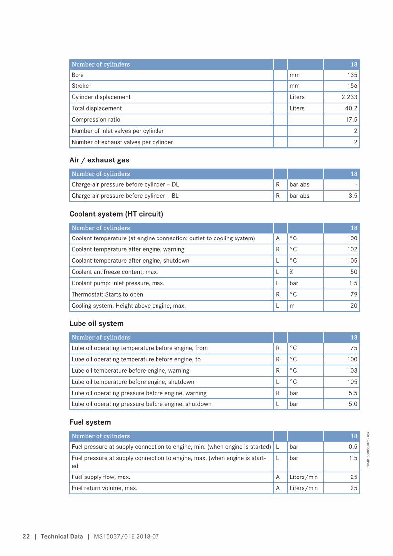
Number of cylinders 18Bore mm 135
Stroke mm 156
Cylinder displacement Liters 2.233
Total displacement Liters 40.2
Compression ratio 17.5
Number of inlet valves per cylinder 2
Number of exhaust valves per cylinder 2
Air / exhaust gasNumber of cylinders 18Charge-air pressure before cylinder – DL R bar abs -
Charge-air pressure before cylinder – BL R bar abs 3.5
Coolant system (HT circuit)Number of cylinders 18Coolant temperature (at engine connection: outlet to cooling system) A °C 100
Coolant temperature after engine, warning R °C 102
Coolant temperature after engine, shutdown L °C 105
Coolant antifreeze content, max. L % 50
Coolant pump: Inlet pressure, max. L bar 1.5
Thermostat: Starts to open R °C 79
Cooling system: Height above engine, max. L m 20
Lube oil systemNumber of cylinders 18Lube oil operating temperature before engine, from R °C 75
Lube oil operating temperature before engine, to R °C 100
Lube oil temperature before engine, warning R °C 103
Lube oil temperature before engine, shutdown L °C 105
Lube oil operating pressure before engine, warning R bar 5.5
Lube oil operating pressure before engine, shutdown L bar 5.0
Fuel systemNumber of cylinders 18Fuel pressure at supply connection to engine, min. (when engine is started) L bar 0.5
Fuel pressure at supply connection to engine, max. (when engine is start-ed)
L bar 1.5
Fuel supply flow, max. A Liters/min 25
Fuel return volume, max. A Liters/min 25
22 | Technical Data | MS15037/01E 2018-07
TIM
-ID: 0
0000
5687
5 - 0
02

General operating dataNumber of cylinders 18Coolant preheating: preheating temperature (min.) L °C 32
Inclinations, standard oil system (reference: waterline)Number of cylinders 18Longitudinal inclination, continuous max. driving end down (option: max.operating inclinations)
L Degrees (°) 5
Longitudinal inclination, continuous max. driving end up (option: max. op-erating inclinations)
L Degrees (°) 5
Transverse inclination, continuous max. (option: max. operating inclina-tions)
L Degrees (°) 10
CapacitiesNumber of cylinders 18Engine coolant, engine-side (w/o cooling system) R Liters 73
Charge-air coolant, engine side R Liters -
Engine oil capacity, initial filling (standard oil system) (option: max. operat-ing inclinations)
R Liters 122
Oil change quantity, max. (standard oil system) (option: max. operating in-clinations)
R Liters 110
Oil pan capacity at dipstick mark “min.” (standard oil system) (option: max.operating inclinations)
L Liters 92
Oil pan capacity at dipstick mark “max.” (standard oil system) (option:max. operating inclinations)
L Liters 102
AcousticsNumber of cylinders 18Exhaust noise, unsilenced – BL (free-field sound pressure level Lp, 1 m dis-tance, ISO 6798, +3 dB(A) tolerance)
R dB(A) 118
Exhaust noise, unsilenced - BL (sound power level LW, ISO 6798+3 dB(A)tolerance)
R dB(A) 131
Engine surface noise with attenuated intake noise (filter) – BL (free-fieldsound pressure level Lp, 1 m distance, ISO 6798, +2 dB(A) tolerance)
R dB(A) 105
Engine surface noise with attenuated intake noise (filter) - DL (sound pow-er level LW, ISO 6798, +2 dB(A) tolerance)
R dB(A) 123
MS15037/01E 2018-07 | Technical Data | 23
TIM
-ID: 0
0000
5687
5 - 0
02

4.2 Firing order
Firing orderNumber of cylinders Firing order18V A1-B6-A3-B4-A5-B2-A7-B1-A9-B3-A8-B5-A6-B7-A4-B9-A2-B8
24 | Technical Data | MS15037/01E 2018-07
TIM
-ID: 0
0000
8014
0 - 0
01

4.3 Engine – Main dimensions
Engine – Main dimensions 18V2000G76S
Engine model Length (A) Width (B) Height (C)18V2000G76S approx. 2611 mm approx. 1572 mm approx. 1420 mm
Table 2: Engine model / dimensions
MS15037/01E 2018-07 | Technical Data | 25
TIM
-ID: 0
0000
8014
1 - 0
01

5 Operation
5.1 Preparing startup after long out-of-service periods (>3 months)
Preconditions☑Engine is stopped and starting disabled.
☑MTU Fluids and Lubricants Specifications (A001061/..) are available.
Startup after long out-of-service periods (>3 months)Item ActionEngine Remove preservative (→ Preservation and Represervation Specifications
(A001070/…)).Lube oil system Check engine oil level (→ Page 125).Fuel system Use appropriate equipment to fill system via fuel supply line.Fuel system Vent (→ Page 94).Coolant circuit If engine is out of service for more than one year, change engine coolant
(→ Page 133).Coolant circuit Check engine coolant level (→ Page 132).Coolant circuit Preheat engine coolant with coolant preheating unit (if fitted).Engine control system Check plug connections (→ Page 178).Engine control system Switch on.
Table 3: Startup after long out-of-service periods (>3 months)
26 | Operation | MS15037/01E 2018-07
TIM
-ID: 0
0000
5473
7 - 0
01

5.2 Preparations for startup after scheduled out-of-service-period
Preconditions☑Engine is stopped and starting disabled.
StartupItem ActionLube oil system Check engine oil level (→ Page 125).Coolant circuit Check engine coolant level (→ Page 132).Coolant circuit Preheat engine coolant with coolant preheating unit, if fitted.Fuel prefilter (if fitted) Drain water, see manufacturer's documentation.Engine control system Switch on.
Table 4: Startup
MS15037/01E 2018-07 | Operation | 27
TIM
-ID: 0
0000
5473
8 - 0
01

5.3 Engine – Starting
Preconditions☑Engine is not under load.
DANGERRotating and moving engine parts.Risk of crushing, danger of parts of the body being caught or pulled in!• Before cranking the engine with starter system, make sure that there are no persons in the engine's
danger zone.
WARNINGStarter heats up during the starting procedure.Risk of burning, in particular to the hands!• Avoid skin contact with the starter.• Wear suitable protective equipment, e.g industrial gloves.
WARNINGHigh level of engine noise when the engine is running.Risk of damage to hearing!• Wear ear protectors.
WARNINGExhaust gases are harmful to health and may cause cancer.Risk of poisoning and suffocation!• Keep the engine room well-ventilated at all times.• Repair leaking exhaust pipework immediately.
Engine startingItem ActionEngine Start the engine (→ documentation of the vehicle manufacturer/plant manu-
facturer).
28 | Operation | MS15037/01E 2018-07
TIM
-ID: 0
0000
1010
7 - 0
08

5.4 Re-starting the engine following an automatic safetyshutdown
NOTICERe-starting the engine following an automatic safety shutdown.Risk of severe engine damage!• Before starting the engine, make sure the root cause of the safety shutdown was eliminated.• If the root cause cannot be identified or eliminated, contact Service.
Note: • If an engine has been shutdown by a fault (red alarm), the engine may only be re-started when the faulthas been identified and eliminated.
Procedure following an automatic safety shutdown1. Eliminate fault.2. If the root cause cannot be identified or eliminated, contact Service.
ImportantThe function "Overdrive safety system" (if fitted), which is only used in emergency situations, is not affect-ed.
MS15037/01E 2018-07 | Operation | 29
TIM
-ID: 0
0000
8138
3 - 0
01

5.5 Operational monitoringDANGER
Components are moving or rotating.Risk of crushing, danger of parts of the body being caught or pulled in!• Operate the engine at low load only. Keep clear of the danger zone of the engine.
WARNINGHigh level of engine noise when the engine is running.Risk of damage to hearing!• Wear ear protectors.
Operational monitoringItem ActionControl and display panels Check readings of operational data (speed, temperature, pressures).
Engine oil Check engine oil level (→ Page 125).
Engine operation Check engine visually for leaks and general condition;Check engine for abnormal running noises, exhaust color and vibrations.
Air filter Check service indicator of air filter (→ Page 124).
Exhaust system Check exhaust color (→ Page 37).
Fuel prefilter (if fitted) Check pointer position of differential pressure gauge at fuel prefilter(→ Page 106)Drain water and contaminants:Fuel prefilter (not switchable)(→ Page 101)Fuel prefilter (switchable) (→ Page 103).
Engine coolant pump Check relief bore (→ Page 137).
30 | Operation | MS15037/01E 2018-07
TIM
-ID: 0
0000
5473
9 - 0
04

5.6 Emission label – Check
Emission label – CheckNote: If there are any irregularities, notify your MTU contact person/service partner without delay.
1. Check that emission labels are present (there can be more than one).2. Check emission label for intactness.3. Check that emission label is fully legible.4. Check content of emission label:
• Does the label on the engine match the label document in the Business Portal/Equipment?• Does the engine number on the emission label match the engine identification plate?• Does the Manufacturing Date match the year of manufacture on the identification plate?
MS15037/01E 2018-07 | Operation | 31
TIM
-ID: 0
0000
6375
2 - 0
02

5.7 Engine shutdown
Preconditions☑Engine is not connected to load.
CAUTIONShutting down from full-load operation may cause hot water to escape from the expansion tank.Risk of scalding!• Allow engine to cool down.• Wear protective clothing, protective gloves, and safety goggles / safety mask.
NOTICEStopping the engine when it is running at full load subjects it to extreme thermal and mechanical stress-es.Overheating of and, therefore, damage to components is possible!• Before shutting down the engine, allow it to idle until the engine temperatures decrease and constant
levels are indicated.
PreparationItem ActionEngine Allow the engine to cool down by running it at idle speed for approx. 5 mi-
nutes.
Stopping the engineItem ActionEngine Stopping (→ Documentation of the vehicle/plant manufacturer).
32 | Operation | MS15037/01E 2018-07
TIM
-ID: 0
0000
1013
8 - 0
07

5.8 Emergency engine shutdownWARNING
Exhaust gases are harmful to health and may cause cancer.Risk of poisoning and suffocation!• Keep the engine room well-ventilated at all times.• Repair leaking exhaust pipework immediately.
CAUTIONShutting down from full-load operation may cause hot water to escape from the expansion tank.Risk of scalding!• Allow engine to cool down.• Wear protective clothing, protective gloves, and safety goggles / safety mask.
NOTICEAn emergency stop subjects the engine system to an extremely high load.Risk of overheating, damage to components!• Trigger an emergency stop only in emergency situations.
Emergency engine shutdownItem ActionEmergency stop pushbutton Press EMERGENCY STOP button (→ Documentation of the vehicle/plant
manufacturer).• Engine is stopped by disconnecting the power supply to the ECU;• Emergency-air shutoff flaps close (if applicable);• Signalization (e.g. by horn, beacon) is activated.
Tripped fusePower failure for an extend-ed time
A power failure leads to an engine shutdown.• The fuel system remains under high residual pressure;• The blank-shot function cannot be performed because there is no power
supply.
After emergency engine shutdownItem ActionControl cabinet, operatorstation etc. (depending onmanufacturer)
Press pushbutton for alarm acknowledgment.• Audible and visual signalization stops.
Engine Manually open emergency-air shutoff flaps (if provided).• Switch on ECU power supply.• Engine is ready for starting.
HP system Energize injectors (for pressure release in HP system using the function„Blank Shot Afterrun“)• Switch on ECU power supply.• Blank Shots are carried out (requires approx. 20 to 30 s.)
MS15037/01E 2018-07 | Operation | 33
TIM
-ID: 0
0000
6246
0 - 0
05

5.9 After stopping the engine
Preconditions☑MTU Preservation and Represervation Specifications (A001070/..) are available.
☑Engine is stopped and starting disabled.
NOTICEEngine coolant with inadequate freeze protection. Water remaining in the pressure sensors freezes attemperatures below 0 °C.Risk of sensor damage!• Remove pressure sensors and shake off residual water.
After stopping the engineItem ActionCoolant circuit Drain engine coolant (→ Page 134) if
• freezing temperatures are expected, the engine is to remain out of servicefor an extended period, but engine coolant has no antifreeze additive.
• the engine room is not heated.• the coolant is not kept at a suitable temperature.• the antifreeze concentration is insufficient for the engine-room tempera-
ture.• the antifreeze concentration is 50% and the engine-room temperature is
below -40°C.Engine control system Switch off (see manufacturer's documentation).Air intake and exhaust sys-tem
If the engine is to be taken out of service for longer than 1 week, seal theengine on the air and exhaust side.If the engine is to be taken out of service for longer than one month, it has tobe preserved (→ MTU Preservation and Represervation Specifications(A001070/..)).
HP system (injector noise) The pressure is released in the system by means of the function “Blank ShotAfterrun”: • Injectors are energized.• A small quantity is injected in the injector return without opening the nee-
dle in the nozzle. (actuation of the injector servo valve without injectingfuel into the combustion chamber).
Explanation: The injectors do not leak permanently, which is why the pres-sure applied in the system during engine stop is maintained. Pressure is onlyreleased through actuation of the injectors. When actuated, the switchedquantities of the servo valve and the injection quantity are discharged. Thisprocedure results in injector noise.Depressurizing (pressure <400 bar) is necessary for the following reasons: • Limitation of load on high-pressure pumps during start• Safety during assembly activities
34 | Operation | MS15037/01E 2018-07
TIM
-ID: 0
0000
5474
0 - 0
03

5.10 Plant – Cleaning
Preconditions☑Engine is stopped and starting disabled.
☑No operating voltage applied.
Special tools, Material, Spare partsDesignation / Use Part No. Qty.
High-pressure cleaner (→ Tools Catalog) 1Cleaner (Hakupur 50/136) X00056700 1
WARNINGCompressed air gun ejects a jet of pressurized air.Risk of injury to eyes and damage to hearing, risk of rupturing internal organs!• Never direct air jet at people.• Always wear safety goggles/face mask and ear defenders.
WARNINGWater jet from high-pressure cleaning unit.Risk of eye injury, risk of scalding!• Do not direct water jet at persons.• Wear protective clothing, protective gloves, and goggles/safety mask.
NOTICECleaning agents should not be left to take effect for too long.Damage to components is possible!• Observe manufacturer's instructions.
NOTICEBlowing down product with compressed air.Entry of dirt and damage to components is possible!• Do not aim compressed air gun directly at seals or electronic components such as connectors or
ECUs.
Cleaning the plant1. Carry out plant cleaning only in areas where an appropriate oil separator is provided (environmental protec-
tion).2. Prior to putting the cleaning unit into operation, read the operating instructions of the high-pressure cleaning
units carefully and observe the safety precautions.3. The following requirements apply for cleaning the plant outside with a high-pressure cleaning unit:
• The pressure of the high-pressure jet (cleaning jet) must not exceed 50 bar.• A minimum distance between spray nozzle and plant of 1 m must be observed.• The temperature of the cleaning medium must not exceed 80 °C.
4. For external cleaning with high-pressure jet, use a fan jet nozzle only.
Note: Never direct compressed air directly at electronic components.5. Carry out external cleaning as follows:
a) Seal all openings in a suitable way.b) Remove coarse dirt.c) Spray on cleaner sparingly and leave it for 1 to 5 minutes.d) Use high-pressure jet to remove loosened dirt.e) Dry engine with compressed air.
MS15037/01E 2018-07 | Operation | 35
TIM
-ID: 0
0000
1017
1 - 0
34
6 Maintenance
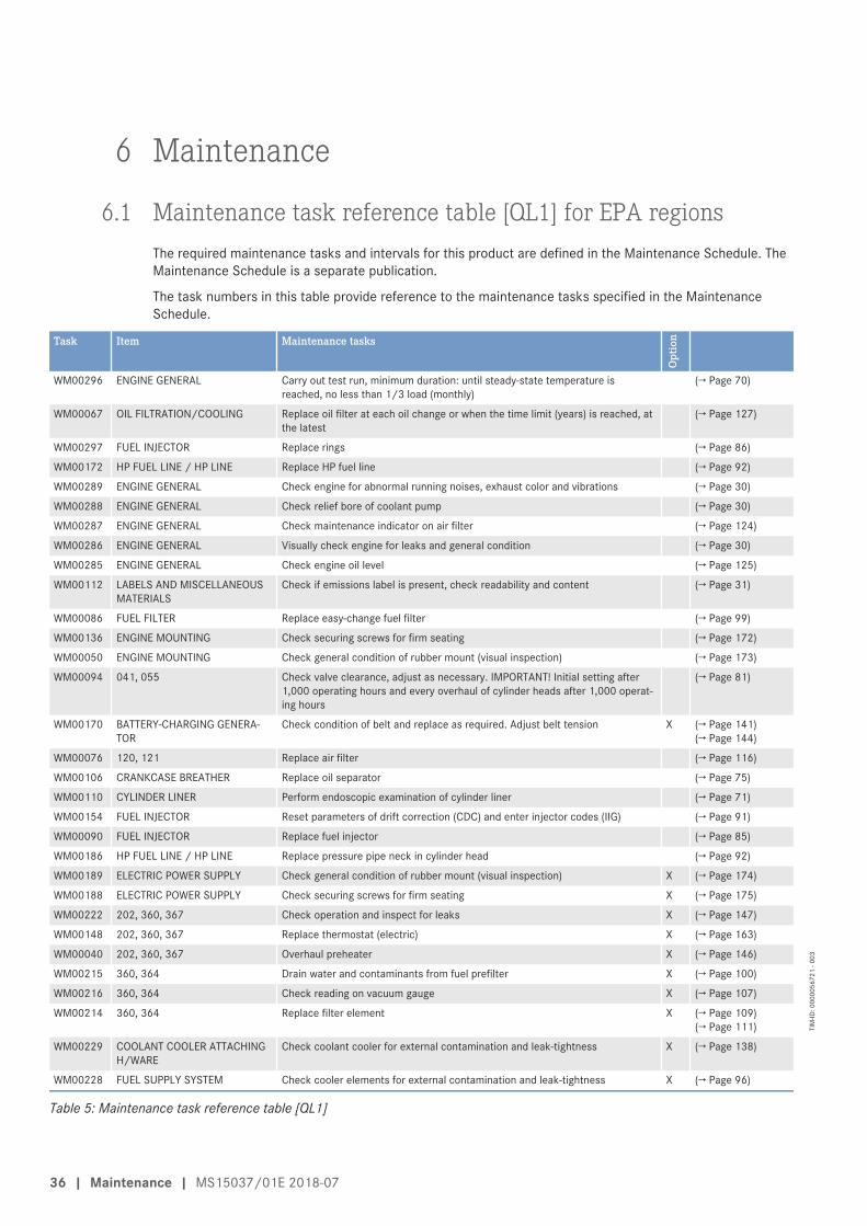
6.1 Maintenance task reference table [QL1] for EPA regionsThe required maintenance tasks and intervals for this product are defined in the Maintenance Schedule. TheMaintenance Schedule is a separate publication.
The task numbers in this table provide reference to the maintenance tasks specified in the MaintenanceSchedule.
Task Item Maintenance tasks
Opt
ion
WM00296 ENGINE GENERAL Carry out test run, minimum duration: until steady-state temperature isreached, no less than 1/3 load (monthly)
(→ Page 70)
WM00067 OIL FILTRATION/COOLING Replace oil filter at each oil change or when the time limit (years) is reached, atthe latest
(→ Page 127)
WM00297 FUEL INJECTOR Replace rings (→ Page 86)
WM00172 HP FUEL LINE / HP LINE Replace HP fuel line (→ Page 92)
WM00289 ENGINE GENERAL Check engine for abnormal running noises, exhaust color and vibrations (→ Page 30)
WM00288 ENGINE GENERAL Check relief bore of coolant pump (→ Page 30)
WM00287 ENGINE GENERAL Check maintenance indicator on air filter (→ Page 124)
WM00286 ENGINE GENERAL Visually check engine for leaks and general condition (→ Page 30)
WM00285 ENGINE GENERAL Check engine oil level (→ Page 125)
WM00112 LABELS AND MISCELLANEOUSMATERIALS
Check if emissions label is present, check readability and content (→ Page 31)
WM00086 FUEL FILTER Replace easy-change fuel filter (→ Page 99)
WM00136 ENGINE MOUNTING Check securing screws for firm seating (→ Page 172)
WM00050 ENGINE MOUNTING Check general condition of rubber mount (visual inspection) (→ Page 173)
WM00094 041, 055 Check valve clearance, adjust as necessary. IMPORTANT! Initial setting after1,000 operating hours and every overhaul of cylinder heads after 1,000 operat-ing hours
(→ Page 81)
WM00170 BATTERY-CHARGING GENERA-TOR
Check condition of belt and replace as required. Adjust belt tension X (→ Page 141)(→ Page 144)
WM00076 120, 121 Replace air filter (→ Page 116)
WM00106 CRANKCASE BREATHER Replace oil separator (→ Page 75)
WM00110 CYLINDER LINER Perform endoscopic examination of cylinder liner (→ Page 71)
WM00154 FUEL INJECTOR Reset parameters of drift correction (CDC) and enter injector codes (IIG) (→ Page 91)
WM00090 FUEL INJECTOR Replace fuel injector (→ Page 85)
WM00186 HP FUEL LINE / HP LINE Replace pressure pipe neck in cylinder head (→ Page 92)
WM00189 ELECTRIC POWER SUPPLY Check general condition of rubber mount (visual inspection) X (→ Page 174)
WM00188 ELECTRIC POWER SUPPLY Check securing screws for firm seating X (→ Page 175)
WM00222 202, 360, 367 Check operation and inspect for leaks X (→ Page 147)
WM00148 202, 360, 367 Replace thermostat (electric) X (→ Page 163)
WM00040 202, 360, 367 Overhaul preheater X (→ Page 146)
WM00215 360, 364 Drain water and contaminants from fuel prefilter X (→ Page 100)
WM00216 360, 364 Check reading on vacuum gauge X (→ Page 107)
WM00214 360, 364 Replace filter element X (→ Page 109)(→ Page 111)
WM00229 COOLANT COOLER ATTACHINGH/WARE
Check coolant cooler for external contamination and leak-tightness X (→ Page 138)
WM00228 FUEL SUPPLY SYSTEM Check cooler elements for external contamination and leak-tightness X (→ Page 96)
Table 5: Maintenance task reference table [QL1]
36 | Maintenance | MS15037/01E 2018-07
TIM
-ID: 0
0000
5672
1 - 0
03

7 Troubleshooting
7.1 Troubleshooting
Engine does not turn when starter is actuatedComponent Cause ActionBattery Low or faulty Charge or replace (see manufacturer's
documentation).Cable connections faulty Check if cable connections are properly
secured (see manufacturer's documen-tation).
Starter Engine cabling or starter faulty Check if cable connections are properlysecured, contact Service.
Engine cabling Faulty Check (→ Page 179).Engine/generatorcontrol system
Assemblies or connectors possibly loose Perform visual inspection (see manufac-turer's documentation).
Engine governor Plug-in connections possibly loose Check plug connections (→ Page 178).Engine Running gear blocked (engine cannot be
barred manually)Contact Service.
Engine turns but does not fireComponent Cause ActionStarter Poor rotation by starter: Battery low or
faultyCharge or replace battery (see manufac-turer's documentation).
Engine cabling Faulty Check (→ Page 179).Fuel system Air in fuel system Vent fuel system (→ Page 94).Engine governor Faulty Contact Service.
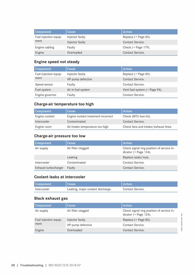
Engine fires unevenlyComponent Cause ActionFuel injection equip-ment
Injector faulty Replace (→ Page 85).HP pump defective Contact Service.
Engine cabling Faulty Check (→ Page 179).Fuel system Air in fuel system Vent fuel system (→ Page 94).Engine governor Faulty Contact Service.
Engine does not reach rated speedComponent Cause ActionFuel supply Fuel prefilter (not switchable) clogged. Replace (→ Page 101).
Fuel prefilter (switchable) clogged. Replace (→ Page 103).Easy-change fuel filter clogged Replace (→ Page 99).
Air supply Air filter clogged Check signal ring position of service in-dicator (→ Page 124).
MS15037/01E 2018-07 | Troubleshooting | 37
TIM
-ID: 0
0000
5189
8 - 0
04
Component Cause ActionFuel injection equip-ment
Injector faulty Replace (→ Page 85).Injector faulty Contact Service.
Engine cabling Faulty Check (→ Page 179).Engine Overloaded Contact Service.
Engine speed not steadyComponent Cause ActionFuel injection equip-ment
Injector faulty Replace (→ Page 85).HP pump defective Contact Service.
Speed sensor Faulty Contact Service.Fuel system Air in fuel system Vent fuel system (→ Page 94).Engine governor Faulty Contact Service.
Charge-air temperature too highComponent Cause ActionEngine coolant Engine coolant treatment incorrect Check (MTU test kit).Intercooler Contaminated Contact Service.Engine room Air-intake temperature too high Check fans and intake/exhaust lines.
Charge-air pressure too lowComponent Cause ActionAir supply Air filter clogged Check signal ring position of service in-
dicator (→ Page 124).Leaking Replace seals/nuts.
Intercooler Contaminated Contact Service.Exhaust turbocharger Faulty Contact Service.
Coolant leaks at intercoolerComponent Cause ActionIntercooler Leaking, major coolant discharge. Contact Service.
Black exhaust gasComponent Cause ActionAir supply Air filter clogged Check signal ring position of service in-
dicator (→ Page 124).Fuel injection equip-ment
Injector faulty Replace (→ Page 85).HP pump defective Contact Service.
Engine Overloaded Contact Service.
38 | Troubleshooting | MS15037/01E 2018-07
TIM
-ID: 0
0000
5189
8 - 0
04

Exhaust gas blueComponent Cause ActionEngine oil Too much engine oil in the engine Drain engine oil (→ Page 126).
Oil separator of crankcase breather con-taminated
Replace (→ Page 75).
Exhaust turbocharger,cylinder head, pistonrings, cylinder liner
Faulty Contact Service.
White exhaust gasComponent Cause ActionEngine Not at operating temperature Run engine to reach operating tempera-
ture.Fuel system Water in fuel Check fuel system on fuel prefilter;
Drain water from fuel prefilter (notswitchable) (→ Page 101).Drain fuel prefilter (switchable)(→ Page 103).
Intercooler Leaking Contact Service.
MS15037/01E 2018-07 | Troubleshooting | 39
TIM
-ID: 0
0000
5189
8 - 0
04

7.2 Engine Control Unit – ECU9 fault messages
Possible engine responses to yellow alarm:Warning, power limitation/reduction, speed limitation, engine shutdown.
Possible engine responses to red alarm:Engine shutdown, power limitation/reduction, speed limitation, warning.
Procedure following an automatic safety shutdown (→ Page 29)
5 – HI T-Charge AirYellow alarm; warning
Cause Corrective action
Charge-air temperature too high(Level 1).
1. Check coolant cooler and intercooler.2. Contact Service if no malfunction can be detected.
6 – SS T-Charge AirRed alarm; emergency stop
Cause Corrective action
Charge-air temperature too high(Level 2).
1. Check coolant cooler and intercooler.2. Contact Service if no malfunction can be detected.
9 – HI T-Coolant IntercoolerYellow alarm; warning
Cause Corrective action
Coolant temperature inintercooler too high (Level 1).
1. Check coolant cooler for leaks, contamination and operation.2. Contact Service if no malfunction can be detected.
10 – SS T-Coolant IntercoolerRed alarm; emergency stop
Cause Corrective action
Coolant temperature inintercooler too high (Level 2).
1. Check coolant cooler for leaks, contamination and operation.2. Contact Service if no malfunction can be detected.
15 – LO P-Lube OilYellow alarm; warning
Cause Corrective action
Lube oil pressure too low (Level1).
1. Check oil level, top up as necessary (→ Page 125).2. Contact Service if no malfunction can be detected.
40 | Troubleshooting | MS15037/01E 2018-07
TIM
-ID: 0
0000
6072
4 - 0
05

16 – SS P-Lube OilRed alarm; emergency stop
Cause Corrective action
Lube oil pressure too low (Level2).
1. Check oil level, top up as necessary (→ Page 125).2. Contact Service if no malfunction can be detected.
23 – LO Coolant LevelRed alarm; emergency stop
Cause Corrective action
Coolant level too low. 1. Check coolant circuit for leaks. Check coolant level in expansiontank, top up as necessary.
2. Contact Service if no malfunction can be detected.
25 – HI P-Diff-Lube OilYellow alarm; warning
Cause Corrective action
Differential oil pressure at oil filtertoo high (Level 1).
u Check oil filter, replace as necessary.
26 – SS P-Diff-Lube OilYellow alarm; warning
Cause Corrective action
Differential oil pressure at oil filtertoo high (Level 2).
u Check oil filter, replace as necessary.
27 – HI Level Leakage FuelYellow alarm; warning
Cause Corrective action
Leak-off fuel level too high. u Contact Service.
30 – SS Engine OverspeedRed alarm; emergency stop
Cause Corrective action
Engine speed too high. u Restart engine.
33 – HI P-Diff-FuelYellow alarm; warning
Cause Corrective action
Differential pressure at fuel filtertoo high (Level 1).
u Check fuel filter, replace as necessary.
MS15037/01E 2018-07 | Troubleshooting | 41
TIM
-ID: 0
0000
6072
4 - 0
05
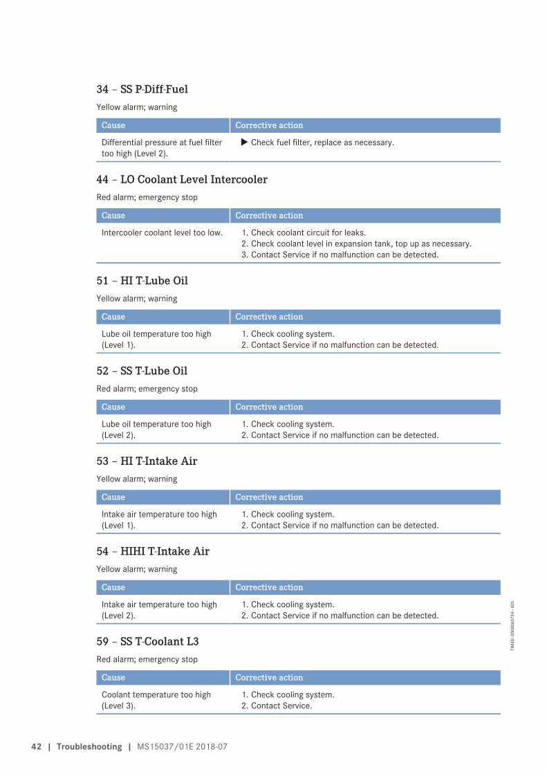
34 – SS P-Diff-FuelYellow alarm; warning
Cause Corrective action
Differential pressure at fuel filtertoo high (Level 2).
u Check fuel filter, replace as necessary.
44 – LO Coolant Level IntercoolerRed alarm; emergency stop
Cause Corrective action
Intercooler coolant level too low. 1. Check coolant circuit for leaks.2. Check coolant level in expansion tank, top up as necessary.3. Contact Service if no malfunction can be detected.
51 – HI T-Lube OilYellow alarm; warning
Cause Corrective action
Lube oil temperature too high(Level 1).
1. Check cooling system.2. Contact Service if no malfunction can be detected.
52 – SS T-Lube OilRed alarm; emergency stop
Cause Corrective action
Lube oil temperature too high(Level 2).
1. Check cooling system.2. Contact Service if no malfunction can be detected.
53 – HI T-Intake AirYellow alarm; warning
Cause Corrective action
Intake air temperature too high(Level 1).
1. Check cooling system.2. Contact Service if no malfunction can be detected.
54 – HIHI T-Intake AirYellow alarm; warning
Cause Corrective action
Intake air temperature too high(Level 2).
1. Check cooling system.2. Contact Service if no malfunction can be detected.
59 – SS T-Coolant L3Red alarm; emergency stop
Cause Corrective action
Coolant temperature too high(Level 3).
1. Check cooling system.2. Contact Service.
42 | Troubleshooting | MS15037/01E 2018-07
TIM
-ID: 0
0000
6072
4 - 0
05

65 – LO P-FuelYellow alarm; warning
Cause Corrective action
Fuel supply pressure too low(Level 1).
1. Check fuel lines for leakage.2. Drain water from fuel prefilter (not switchable) (→ Page 101).
Drain water from fuel prefilter (switchable) (→ Page 103).3. Replace filter element of fuel prefilter (not switchable)
(→ Page 109).Replace filter element of fuel prefilter (switchable) (→ Page 111).
4. Replace main fuel filter and, if required, intermediate fuel filter(→ Page 99).
66 – SS P-FuelRed alarm; emergency stop
Cause Corrective action
Fuel supply pressure too low(Level 2).
1. Check fuel lines for leakage.2. Drain water from fuel prefilter (not switchable) (→ Page 101).
Drain water from fuel prefilter (switchable) (→ Page 103).3. Replace filter element of fuel prefilter (not switchable)
(→ Page 109).Replace filter element of fuel prefilter (switchable) (→ Page 111).
4. Replace main fuel filter and, if required, intermediate fuel filter(→ Page 99).
67 – HI T-CoolantYellow alarm; warning
Cause Corrective action
Coolant temperature too high(Level 1).
1. Check cooling system.2. Contact Service if no malfunction can be detected.
68 – SS T-CoolantRed alarm; emergency stop (3 min. delay)
Cause Corrective action
Coolant temperature too high(Level 2).
1. Check cooling system.2. Contact Service if no malfunction can be detected.
81 – AL Rail LeakageYellow alarm; warning
Cause Corrective action
Rail pressure gradient too low forstart or too high for stop => HPfuel system leaky, air in system.
1. On engine stopping: Seal off system, contact Service2. On engine starting: Check engine for leakage, if none found,
attempt restarting as per operating instructions (air in system).
MS15037/01E 2018-07 | Troubleshooting | 43
TIM
-ID: 0
0000
6072
4 - 0
05

82 – HI P-Fuel (Common Rail)Yellow alarm; warning
Cause Corrective action
Rail pressure > Set value => HPfuel control block jamming orwiring faulty.
1. Check wiring of HP fuel control block.2. Contact Service if no fault can be detected.
83 – LO P-Fuel (Common Rail)Yellow alarm; warning
Cause Corrective action
Rail pressure < set value; Suctionrestrictor of HP fuel control blockfaulty or leakage in HP fuelsystem.
1. Check wiring of HP fuel control block.2. Check high-pressure system for leaks.3. Contact Service if no fault can be detected.
89 – SS Engine Speed too LowYellow alarm; warning
Cause Corrective action
Engine speed too low. 1. Restart engine (→ Page 28).2. Observe any other messages.
90 – SS Idle Speed Not ReachedYellow alarm; warning
Cause Corrective action
Idling speed not reached, startaborted.
1. Restart engine (→ Page 28).2. Observe any other messages.
91 – SS Release Speed Not ReachedYellow alarm; warning
Cause Corrective action
Run-up speed not reached, startaborted.
1. Restart engine (→ Page 28).2. Observe any other messages.
92 – SS Starter Speed Mot ReachedYellow alarm; warning
Cause Corrective action
Starter speed not reached;termination of starting sequence;starter does not turn or turnsslowly.
1. Check battery.2. Check wiring and voltage supply.3. Check fuel supply.4. Restart engine (→ Page 28).5. Observe any other messages.
44 | Troubleshooting | MS15037/01E 2018-07
TIM
-ID: 0
0000
6072
4 - 0
05

93 – SS T-PreheatRed alarm; engine start interlock
Cause Corrective action
Preheating temperature too low(Level 2); coolant temperature toolow for engine start.
1. Extend preheating period.2. Check preheater.
94 – LO T-PreheatYellow alarm; warning
Cause Corrective action
Preheating temperature too low(Level 1); coolant temperature toolow for engine start.
1. Extend preheating period.2. Check preheater.
95 – AL Prelubrication FaultYellow alarm; warning
Cause Corrective action
Oil priming fault. u Contact Service.
102 – AL Fuel Cons. Meter DefectYellow alarm; warning
Cause Corrective action
Consumption meter faulty. u Replace Engine Control Unit at next opportunity.
104 – AL Eng Hours Counter DefectYellow alarm; warning
Cause Corrective action
Hour meter faulty. u Replace Engine Control Unit at next opportunity.
118 – LO ECU Power Supply VoltageYellow alarm; warning
Cause Corrective action
Supply voltage too low (Level 1). u Check batteries, charge as necessary; check alternator.
119 – LOLO ECU Power Supply VoltageYellow alarm; warning
Cause Corrective action
Supply voltage too low (Level 2). u Check batteries, charge as necessary; check alternator.
MS15037/01E 2018-07 | Troubleshooting | 45
TIM
-ID: 0
0000
6072
4 - 0
05

120 – HI ECU Power Supply VoltageYellow alarm; warning
Cause Corrective action
Supply voltage too high (Level 1). u Check batteries, charge as necessary; check alternator.
121 – HIHI ECU Power Supply VoltageYellow alarm; warning
Cause Corrective action
Supply voltage too high (Level 2). u Check batteries, charge as necessary; check alternator.
122 – HI T-ECUYellow alarm; warning
Cause Corrective action
Temperature in ECS too high. u Check engine room ventilation.
141 – AL Power too highYellow alarm; warning
Cause Corrective action
The average power rate over thelast 24 hours of engine operationhas exceeded the set maximumvalue.
u Reduce power.
180 – AL CAN1 Node LostYellow alarm; warning
Cause Corrective action
Connection to a node on CAN bus1 failed.
1. Check devices connected to CAN.2. Check wiring (termination resistor installed?).
181 – AL CAN2 Node LostYellow alarm; warning
Cause Corrective action
Connection to a node on CAN bus2 failed.
1. Check devices connected to CAN.2. Check wiring (termination resistor installed?).
182 – AL CAN Wrong ParametersYellow alarm; warning
Cause Corrective action
Incorrect parameter valuesentered in data record.
u Contact Service.
46 | Troubleshooting | MS15037/01E 2018-07
TIM
-ID: 0
0000
6072
4 - 0
05

183 – AL CAN No PU-DataYellow alarm; warning
Cause Corrective action
The selected CAN mode initializescommunication by means of thePU data module. However, therequired PU data module is notavailable or not valid.
1. Check devices connected to CAN.2. Contact Service.
184 – AL CAN PU-Data Flash ErrorYellow alarm; warning
Cause Corrective action
A programming error occurredwhen attempting to copy areceived PU data module into theFlash module.
u Contact Service.
186 – AL CAN1 Bus OffYellow alarm; warning
Cause Corrective action
CAN controller 1 is in “Bus-Off”status.
1. Check CAN bus for short circuit, rectify short circuit as necessary.2. Check shielding, improve shielding as necessary.3. Contact Service.
187 – AL CAN1 Error PassiveYellow alarm; warning
Cause Corrective action
CAN controller 1 has signaled awarning.
1. Check CAN bus for short circuit, rectify short circuit as necessary.2. Check shielding, improve shielding as necessary.3. Contact Service.
188 – AL CAN2 Bus OffYellow alarm; warning
Cause Corrective action
CAN controller 2 is in “Bus-Off”status.
1. Check CAN bus for short circuit, rectify short circuit as necessary.2. Check shielding, improve shielding as necessary.3. Contact Service.
189 – AL CAN2 Error PassiveYellow alarm; warning
Cause Corrective action
CAN controller 2 has signaled awarning.
1. Check CAN bus for short circuit, rectify short circuit as necessary.2. Check shielding, improve shielding as necessary.3. Contact Service.
MS15037/01E 2018-07 | Troubleshooting | 47
TIM
-ID: 0
0000
6072
4 - 0
05

201 – SD T-CoolantYellow alarm; warning
Cause Corrective action
Coolant temperature sensorfaulty.
u Check sensor B6 and wiring, replace as necessary (→ Page 179).
203 – SD T-Charge AirYellow alarm; warning
Cause Corrective action
Charge-air temperature sensorfaulty.
u Check sensor B9 and wiring, replace as necessary (→ Page 179).
205 – SD T-Coolant IntercoolerYellow alarm; warning
Cause Corrective action
Intercooler coolant temperaturesensor faulty.
u Check sensor B26 and wiring, replace as necessary (→ Page 179).
208 – SD P-Charge AirYellow alarm; warning
Cause Corrective action
Charge-air pressure sensor faulty. u Check sensor B10 and wiring, replace as necessary (→ Page 179).
211 – SD P-Lube OilYellow alarm; warning
Cause Corrective action
Lube-oil pressure sensor faulty. u Check sensor B5.1 and wiring, replace as necessary (→ Page 179).
215 – SD P-HDYellow alarm; warning
Cause Corrective action
Rail pressure sensor faulty; High-pressure governor emergencyoperation
u Check sensor B48.1 and wiring, replace as necessary(→ Page 179).
216 – SD T-Lube OilYellow alarm; warning
Cause Corrective action
Lube oil temperature sensorfaulty.
u Check sensor B7 and wiring, replace as necessary (→ Page 179).
48 | Troubleshooting | MS15037/01E 2018-07
TIM
-ID: 0
0000
6072
4 - 0
05

219 – SD T-Intake AirYellow alarm; warning
Cause Corrective action
Intake air temperature sensorfaulty.
u Check sensor B3 and wiring, replace as necessary (→ Page 179).
220 – SD Level Coolant WaterYellow alarm; warning
Cause Corrective action
Coolant level sensor faulty. 1. Check sensor F33 and wiring, replace as necessary (→ Page 179).2. Fault is rectified when electronics are switched back on.
221 – SD P-Diff Lube OilYellow alarm; warning
Cause Corrective action
Lube oil differential pressuresensor faulty.
u Check sensor B5.1 and B5.3 and wiring, replace as necessary(→ Page 179).
222 – SD Leak Fuel LevelYellow alarm; warning
Cause Corrective action
Leak-off fuel level sensor faulty. u Check sensor F46 and wiring, replace as necessary (→ Page 179).
223 – SD Level Coolant IntercoolerYellow alarm; warning
Cause Corrective action
Coolant level sensor forintercooler faulty.
1. Check sensor F57 and wiring, replace as necessary (→ Page 179).2. Fault is rectified when electronics are switched back on.
227 – SD P-Oil before FilterYellow alarm; warning
Cause Corrective action
Sensor for lube oil pressurebefore filter faulty.
u Check sensor B5.3 and wiring, replace as necessary (→ Page 179).
228 – SD P-Fuel before FilterYellow alarm; warning
Cause Corrective action
Fuel pressure sensor (before mainfilter) faulty.
u Check sensor B34.2 and wiring, replace as necessary(→ Page 179).
MS15037/01E 2018-07 | Troubleshooting | 49
TIM
-ID: 0
0000
6072
4 - 0
05

229 – AL Stop Camshaft Sensor DefectRed alarm; emergency stop
Cause Corrective action
Engine stop due to camshaftsensor fault and a previouscrankshaft sensor fault in thesame operating cycle.
1. Check sensor and wiring to connectors B1 and B13, replace asnecessary (→ Page 179).
2. Acknowledge alarm.3. Restart engine (→ Page 28).
230 – SD Crankshaft SpeedYellow alarm; warning
Cause Corrective action
Crankshaft sensor faulty. 1. Check sensor B13 and wiring, replace as necessary (→ Page 179).2. Fault is rectified when engine is restarted, contact Service if this is
not the case.
231 – SD Camshaft SpeedYellow alarm; warning
Cause Corrective action
Camshaft sensor faulty. 1. Check sensor B1 and wiring, replace as necessary (→ Page 179).2. Fault is rectified when engine is restarted, contact Service if this is
not the case.
239 – SD P-Diff FuelYellow alarm; warning
Cause Corrective action
Fuel pressure sensors faulty. u Check sensor B34.2, sensor 34.3 and wiring, replace as necessary(→ Page 179).
240 – SD P-FuelYellow alarm; warning
Cause Corrective action
Fuel pressure sensor beforeintermediate filter faulty.
u Check sensor B34.3 and wiring, replace as necessary(→ Page 179).
245 – SD ECU Power Supply VoltageYellow alarm; warning
Cause Corrective action
Internal ECU fault. u Replace Engine Control Unit.
50 | Troubleshooting | MS15037/01E 2018-07
TIM
-ID: 0
0000
6072
4 - 0
05

266 – SD Speed DemandYellow alarm; warning
Cause Corrective action
Analog speed setting faulty. 1. Check speed setting transmitter and wiring, replace as necessary(→ Page 179).
2. Fault is rectified when engine is restarted.
269 – SD Loadp. Analog fil.Yellow alarm; warning
Cause Corrective action
Filtered analog signal of loadpulse missing.
1. Check wiring, replace as necessary.2. Fault is rectified when engine is restarted.
270 – SD Frequency InputYellow alarm; warning
Cause Corrective action
Frequency input faulty. 1. Check speed setting transmitter and wiring, replace as necessary(→ Page 179).
2. Fault is rectified when engine is restarted.
321 – AL Wiring Cylinder A1Yellow alarm; warning
Cause Corrective action
Short circuit in cylinder A1injector wiring. Result: Misfiring.
1. Check injector wiring.2. Rectify injector solenoid valve short circuit (positive to negative)
(e.g. by exchanging injectors).3. Fault is rectified when engine is restarted.
322 – AL Wiring Cylinder A2Yellow alarm; warning
Cause Corrective action
Short circuit in cylinder A2injector wiring. Result: Misfiring.
1. Check injector wiring.2. Rectify injector solenoid valve short circuit (positive to negative)
(e.g. by exchanging injectors).3. Fault is rectified when engine is restarted.
323 – AL Wiring Cylinder A3Yellow alarm; warning
Cause Corrective action
Short circuit in cylinder A3injector wiring. Result: Misfiring.
1. Check injector wiring.2. Rectify injector solenoid valve short circuit (positive to negative)
(e.g. by exchanging injectors).3. Fault is rectified when engine is restarted.
MS15037/01E 2018-07 | Troubleshooting | 51
TIM
-ID: 0
0000
6072
4 - 0
05

324 – AL Wiring Cylinder A4Yellow alarm; warning
Cause Corrective action
Short circuit in cylinder A4injector wiring. Result: Misfiring.
1. Check injector wiring.2. Rectify injector solenoid valve short circuit (positive to negative)
(e.g. by exchanging injectors).3. Fault is rectified when engine is restarted.
325 – AL Wiring Cylinder A5Yellow alarm; warning
Cause Corrective action
Short circuit in cylinder A5injector wiring. Result: Misfiring.
1. Check injector wiring.2. Rectify injector solenoid valve short circuit (positive to negative)
(e.g. by exchanging injectors).3. Fault is rectified when engine is restarted.
326 – AL Wiring Cylinder A6Yellow alarm; warning
Cause Corrective action
Short circuit in cylinder A6injector wiring. Result: Misfiring.
1. Check injector wiring.2. Rectify injector solenoid valve short circuit (positive to negative)
(e.g. by exchanging injectors).3. Fault is rectified when engine is restarted.
327 – AL Wiring Cylinder A7Yellow alarm; warning
Cause Corrective action
Short circuit in cylinder A7injector wiring. Result: Misfiring.
1. Check injector wiring.2. Rectify injector solenoid valve short circuit (positive to negative)
(e.g. by exchanging injectors).3. Fault is rectified when engine is restarted.
328 – AL Wiring Cylinder A8Yellow alarm; warning
Cause Corrective action
Short circuit in cylinder A8injector wiring. Result: Misfiring.
1. Check injector wiring.2. Rectify injector solenoid valve short circuit (positive to negative)
(e.g. by exchanging injectors).3. Fault is rectified when engine is restarted.
52 | Troubleshooting | MS15037/01E 2018-07
TIM
-ID: 0
0000
6072
4 - 0
05

329 – AL Wiring Cylinder A9Yellow alarm; warning
Cause Corrective action
Short circuit in cylinder A9injector wiring. Result: Misfiring.
1. Check injector wiring.2. Rectify injector solenoid valve short circuit (positive to negative)
(e.g. by exchanging injectors).3. Fault is rectified when engine is restarted.
331 – AL Wiring Cylinder B1Yellow alarm; warning
Cause Corrective action
Short circuit in cylinder B1injector wiring. Result: Misfiring.
1. Check injector wiring.2. Rectify injector solenoid valve short circuit (positive to negative)
(e.g. by exchanging injectors).3. Fault is rectified when engine is restarted.
332 – AL Wiring Cylinder B2Yellow alarm; warning
Cause Corrective action
Short circuit in cylinder B2injector wiring. Result: Misfiring.
1. Check injector wiring.2. Rectify injector solenoid valve short circuit (positive to negative)
(e.g. by exchanging injectors).3. Fault is rectified when engine is restarted.
333 – AL Wiring Cylinder B3Yellow alarm; warning
Cause Corrective action
Short circuit in cylinder B3injector wiring. Result: Misfiring.
1. Check injector wiring.2. Rectify injector solenoid valve short circuit (positive to negative)
(e.g. by exchanging injectors).3. Fault is rectified when engine is restarted.
334 – AL Wiring Cylinder B4Yellow alarm; warning
Cause Corrective action
Short circuit in cylinder B4injector wiring. Result: Misfiring.
1. Check injector wiring.2. Rectify injector solenoid valve short circuit (positive to negative)
(e.g. by exchanging injectors).3. Fault is rectified when engine is restarted.
MS15037/01E 2018-07 | Troubleshooting | 53
TIM
-ID: 0
0000
6072
4 - 0
05

335 – AL Wiring Cylinder B5Yellow alarm; warning
Cause Corrective action
Short circuit in cylinder B5injector wiring. Result: Misfiring.
1. Check injector wiring.2. Rectify injector solenoid valve short circuit (positive to negative)
(e.g. by exchanging injectors).3. Fault is rectified when engine is restarted.
336 – AL Wiring Cylinder B6Yellow alarm; warning
Cause Corrective action
Short circuit in cylinder B6injector wiring. Result: Misfiring.
1. Check injector wiring.2. Rectify injector solenoid valve short circuit (positive to negative)
(e.g. by exchanging injectors).3. Fault is rectified when engine is restarted.
337 – AL Wiring Cylinder B7Yellow alarm; warning
Cause Corrective action
Short circuit in cylinder B7injector wiring. Result: Misfiring.
1. Check injector wiring.2. Rectify injector solenoid valve short circuit (positive to negative)
(e.g. by exchanging injectors).3. Fault is rectified when engine is restarted.
338 – AL Wiring Cylinder B8Yellow alarm; warning
Cause Corrective action
Short circuit in cylinder B8injector wiring. Result: Misfiring.
1. Check injector wiring.2. Rectify injector solenoid valve short circuit (positive to negative)
(e.g. by exchanging injectors).3. Fault is rectified when engine is restarted.
339 – AL Wiring Cylinder B9Yellow alarm; warning
Cause Corrective action
Short circuit in cylinder B9injector wiring. Result: Misfiring.
1. Check injector wiring.2. Rectify short circuit of injector solenoid valve (positive to negative)
(e.g. by exchanging injectors).3. Fault is rectified when engine is restarted.
54 | Troubleshooting | MS15037/01E 2018-07
TIM
-ID: 0
0000
6072
4 - 0
05

341 – AL Open Load Cylinder A1Yellow alarm; warning
Cause Corrective action
Open circuit in cylinder A1injector wiring. Result: Misfiring.
1. Check injector wiring, exclude disruption in solenoid valve (e.g. byexchanging injectors).
2. Fault is rectified after each working cycle.
342 – AL Open Load Cylinder A2Yellow alarm; warning
Cause Corrective action
Open circuit in cylinder A2injector wiring. Result: Misfiring.
1. Check injector wiring, exclude disruption in solenoid valve (e.g. byexchanging injectors).
2. Fault is rectified after each working cycle.
343 – AL Open Load Cylinder A3Yellow alarm; warning
Cause Corrective action
Open circuit in cylinder A3injector wiring. Result: Misfiring.
1. Check injector wiring, exclude disruption in solenoid valve (e.g. byexchanging injectors).
2. Fault is rectified after each working cycle.
344 – AL Open Load Cylinder A4Yellow alarm; warning
Cause Corrective action
Open circuit in cylinder A4injector wiring. Result: Misfiring.
1. Check injector wiring, exclude disruption in solenoid valve (e.g. byexchanging injectors).
2. Fault is rectified after each working cycle.
345 – AL Open Load Cylinder A5Yellow alarm; warning
Cause Corrective action
Open circuit in cylinder A5injector wiring. Result: Misfiring.
1. Check injector wiring, exclude disruption in solenoid valve (e.g. byexchanging injectors).
2. Fault is rectified after each working cycle.
346 – AL Open Load Cylinder A6Yellow alarm; warning
Cause Corrective action
Open circuit in cylinder A6injector wiring. Result: Misfiring.
1. Check injector wiring, exclude disruption in solenoid valve (e.g. byexchanging injectors).
2. Fault is rectified after each working cycle.
MS15037/01E 2018-07 | Troubleshooting | 55
TIM
-ID: 0
0000
6072
4 - 0
05
347 – AL Open Load Cylinder A7Yellow alarm; warning
Cause Corrective action
Open circuit in cylinder A7injector wiring. Result: Misfiring.
1. Check injector wiring, exclude disruption in solenoid valve (e.g. byexchanging injectors).
2. Fault is rectified after each working cycle.
348 – AL Open Load Cylinder A8Yellow alarm; warning
Cause Corrective action
Open circuit in cylinder A8injector wiring. Result: Misfiring.
1. Check injector wiring, exclude disruption in solenoid valve (e.g. byexchanging injectors).
2. Fault is rectified after each working cycle.
349 – AL Open Load Cylinder A9Yellow alarm; warning
Cause Corrective action
Open circuit in cylinder A9injector wiring. Result: Misfiring.
1. Check injector wiring, exclude disruption in solenoid valve (e.g. byexchanging injectors).
2. Fault is rectified after each working cycle.
351 – AL Open Load Cylinder B1Yellow alarm; warning
Cause Corrective action
Open circuit in cylinder B1injector wiring. Result: Misfiring.
1. Check injector wiring, exclude disruption in solenoid valve (e.g. byexchanging injectors).
2. Fault is rectified after each working cycle.
352 – AL Open Load Cylinder B2Yellow alarm; warning
Cause Corrective action
Open circuit in cylinder B2injector wiring. Result: Misfiring.
1. Check injector wiring, exclude disruption in solenoid valve (e.g. byexchanging injectors).
2. Fault is rectified after each working cycle.
353 – AL Open Load Cylinder B3Yellow alarm; warning
Cause Corrective action
Open circuit in cylinder B3injector wiring. Result: Misfiring.
1. Check injector wiring, exclude disruption in solenoid valve (e.g. byexchanging injectors).
2. Fault is rectified after each working cycle.
56 | Troubleshooting | MS15037/01E 2018-07
TIM
-ID: 0
0000
6072
4 - 0
05

354 – AL Open Load Cylinder B4Yellow alarm; warning
Cause Corrective action
Open circuit in cylinder B4injector wiring. Result: Misfiring.
1. Check injector wiring, exclude disruption in solenoid valve (e.g. byexchanging injectors).
2. Fault is rectified after each working cycle.
355 – AL Open Load Cylinder B5Yellow alarm; warning
Cause Corrective action
Open circuit in cylinder B5injector wiring. Result: Misfiring.
1. Check injector wiring, exclude disruption in solenoid valve (e.g. byexchanging injectors).
2. Fault is rectified after each working cycle.
356 – AL Open Load Cylinder B6Yellow alarm; warning
Cause Corrective action
Open circuit in cylinder B6injector wiring. Result: Misfiring.
1. Check injector wiring, exclude disruption in solenoid valve (e.g. byexchanging injectors).
2. Fault is rectified after each working cycle.
357 – AL Open Load Cylinder B7Yellow alarm; warning
Cause Corrective action
Open circuit in cylinder B7injector wiring. Result: Misfiring.
1. Check injector wiring, exclude disruption in solenoid valve (e.g. byexchanging injectors).
2. Fault is rectified after each working cycle.
358 – AL Open Load Cylinder B8Yellow alarm; warning
Cause Corrective action
Open circuit in cylinder B8injector wiring. Result: Misfiring.
1. Check injector wiring, exclude disruption in solenoid valve (e.g. byexchanging injectors).
2. Fault is rectified after each working cycle.
359 – AL Open Load Cylinder B9Yellow alarm; warning
Cause Corrective action
Open circuit in cylinder B9injector wiring. Result: Misfiring.
1. Check injector wiring, exclude disruption in solenoid valve (e.g. byexchanging injectors).
2. Fault is rectified after each working cycle.
MS15037/01E 2018-07 | Troubleshooting | 57
TIM
-ID: 0
0000
6072
4 - 0
05

361 – AL Power Stage LowYellow alarm; warning
Cause Corrective action
Internal electronic fault,electronics possibly faulty.
1. Start engine governor self-test.2. Replace ECU in case of fault; if self-test diagnoses “Electronics OK”
check for additional fault messages (e.g. wiring fault).
362 – AL Power Stage HighYellow alarm; warning
Cause Corrective action
Internal electronic fault,electronics possibly faulty.
1. Start engine governor self-test.2. Replace ECU in case of fault; if self-test diagnoses “Electronics OK”
check for additional fault messages (e.g. wiring fault).
363 – AL Stop Power StageRed alarm; self-restoring
Cause Corrective action
Internal electronic fault,electronics possibly faulty.
1. Start engine governor self-test.2. Replace ECU in case of fault; if self-test diagnoses “Electronics OK”
check for additional fault messages (e.g. wiring fault).
365 – AL Stop MV-Wiring GroundRed alarm; self-restoring
Cause Corrective action
Injector wiring fault. u Check wiring, replace wiring harness as necessary.
381 – AL Wiring TOP 1Yellow alarm; warning
Cause Corrective action
Short circuit or wire break ontransistor output 1 plant-side(TOP 1).
u Check wiring (→ Page 179).
382 – AL Wiring TOP 2Yellow alarm; warning
Cause Corrective action
Short circuit or wire break ontransistor output 2 plant-side(TOP 2).
u Check wiring (→ Page 179).
58 | Troubleshooting | MS15037/01E 2018-07
TIM
-ID: 0
0000
6072
4 - 0
05

383 – AL Wiring TOP 3Yellow alarm; warning
Cause Corrective action
Short circuit or wire break ontransistor output 3 plant-side(TOP 3).
u Check wiring (→ Page 179).
384 – AL Wiring TOP 4Yellow alarm; warning
Cause Corrective action
Short circuit or wire break ontransistor output 4 plant-side(TOP 4).
u Check wiring (→ Page 179).
390 – AL MCR exceededYellow alarm; warning
Cause Corrective action
DBR/MCR function: MCR(continuous maximum rate) wasexceeded.
1. No action required if alarm only applied temporarily.2. Contact Service if alarm applied constantly.
400 – AL Open Load Digital Input 1Yellow alarm; warning
Cause Corrective action
Line disruption at digital input 1. u Check wiring (→ Page 179).
401 – AL Open Load Digital Input 2Yellow alarm; warning
Cause Corrective action
Line disruption at digital input 2. u Check wiring (→ Page 179).
402 – AL Open Load Digital Input 3Yellow alarm; warning
Cause Corrective action
Line disruption at digital input 3. u Check wiring (→ Page 179).
403 – AL Open Load Digital Input 4Yellow alarm; warning
Cause Corrective action
Line disruption at digital input 4. u Check wiring (→ Page 179).
MS15037/01E 2018-07 | Troubleshooting | 59
TIM
-ID: 0
0000
6072
4 - 0
05

404 – AL Open Load Digital Input 5Yellow alarm; warning
Cause Corrective action
Line disruption at digital input 5. u Check wiring (→ Page 179).
405 – AL Open Load Digital Input 6Yellow alarm; warning
Cause Corrective action
Line disruption at digital input 6. u Check wiring (→ Page 179).
406 – AL Open Load Digital Input 7Yellow alarm; warning
Cause Corrective action
Line disruption at digital input 7. u Check wiring (→ Page 179).
407 – AL Open Load Digital Input 8Yellow alarm; warning
Cause Corrective action
Line disruption at digital input 8. u Check wiring (→ Page 179).
408 – AL Open Load Emerg. Stop Input ESIYellow alarm; warning
Cause Corrective action
Open circuit at input foremergency stop.
u Check wiring (→ Page 179).
410 – LO U-PDUYellow alarm; warning
Cause Corrective action
Injector voltage too low (Level 1). u Perform Engine Control Unit self-test, replace as necessary.
411 – LOLO U-PDUYellow alarm; warning
Cause Corrective action
Injector voltage too low (Level 2). u Perform Engine Control Unit self-test, replace as necessary.
412 – HI U-PDUYellow alarm; warning
Cause Corrective action
Injector voltage too high (Level 1). u Perform Engine Control Unit self-test, replace as necessary.
60 | Troubleshooting | MS15037/01E 2018-07
TIM
-ID: 0
0000
6072
4 - 0
05

413 – HIHI U-PDUYellow alarm; warning
Cause Corrective action
Injector voltage too high (Level 2). u Perform Engine Control Unit self-test, replace as necessary.
414 – HI Level Water Fuel PrefilterYellow alarm; warning
Cause Corrective action
Water level in fuel prefilter toohigh.
u Empty fuel prefilter.
415 – LO P-Coolant IntercoolerYellow alarm; warning
Cause Corrective action
Coolant pressure in intercoolertoo low (Level 1).
1. Check coolant level in expansion tank, top up as necessary.2. Check coolant circuit for leaks.3. Check coolant pump.
416 – SS P-Coolant IntercoolerYellow alarm; warning
Cause Corrective action
Coolant pressure in intercoolertoo low (Level 2).
1. Check coolant level in expansion tank, top up as necessary.2. Check coolant circuit for leaks.3. Check coolant pump.
417 – SD Level Water Fuel PrefilterYellow alarm; warning
Cause Corrective action
Water level sensor of fuel prefilterfaulty, short circuit or wire break.
u Check sensor F70 and wiring, replace as necessary .
438 – LO P-Fuel 2 (Common Rail)Yellow alarm; warning
Cause Corrective action
Rail pressure below specifiedvalue.Suction restrictor of HP fuelcontrol block faulty or leakage inHP fuel system.
u Contact Service.
MS15037/01E 2018-07 | Troubleshooting | 61
TIM
-ID: 0
0000
6072
4 - 0
05

439 – HI P-Fuel 2 (Common Rail)Yellow alarm; warning
Cause Corrective action
Rail pressure above specifiedvalue.Suction restrictor of HP fuel blockjamming or HP fuel control blockwiring faulty.
1. Check wiring of HP fuel control block.2. Contact Service if no fault can be detected.
441 – AL Rail 2 LeakageYellow alarm; warning
Cause Corrective action
Pressure gradient in rail is too lowduring starting or too high duringstopping.
1. On engine stopping: Seal off system, contact Service.2. On engine starting: Check engine for leakage, if none found,
attempt restarting as per operating instructions (air in system).
444 – SD U-PDUYellow alarm; warning
Cause Corrective action
Sensor defect of injector powerstage.
u Replace Engine Control Unit.
445 – SD P-Ambient AirYellow alarm; warning
Cause Corrective action
Ambient air pressure sensorfaulty.
u Replace Engine Control Unit (sensor is in the ECU).
446 – SD P-HD2Yellow alarm; warning
Cause Corrective action
Rail pressure sensor faulty, high-pressure regulator emergencymode.
u Check sensor B48.2 and wiring, replace as necessary(→ Page 179).
450 – SD Idle/End-Torque Input [%]Yellow alarm; warning
Cause Corrective action
Input signal for initial/final torquefaulty.
1. Check signal transmitter and wiring, replace as necessary.2. Restart engine (→ Page 28).
62 | Troubleshooting | MS15037/01E 2018-07
TIM
-ID: 0
0000
6072
4 - 0
05

454 – SS Power Reduction ActiveYellow alarm; warning
Cause Corrective action
Power reduction activated. u Observe any other messages.
470 – SD T-ECUYellow alarm; warning
Cause Corrective action
Temperature sensor for enginegovernor faulty.
u Replace Engine Control Unit at next opportunity.
471 – SD Coil CurrentYellow alarm; warning
Cause Corrective action
Control of HP fuel control blockfaulty.
1. Check HP fuel control block and wiring, replace as necessary(→ Page 179).
2. Fault is rectified when engine is restarted.
472 – AL Stop SDRed alarm; emergency stop
Cause Corrective action
Sensor fault of shutdownchannels.
u Contact Service.
474 – AL Wiring FOYellow alarm; warning
Cause Corrective action
Wire break or short circuit at FOchannel.
u Contact Service.
476 – AL Crash Rec. Init. ErrorYellow alarm; warning
Cause Corrective action
Initialization error of crashrecorder.
u Contact Service.
478 – AL Comb. Alarm Yel (Plant)Yellow alarm; warning
Cause Corrective action
Combined alarm initiated by plant(yellow).
u Observe any other fault messages.
MS15037/01E 2018-07 | Troubleshooting | 63
TIM
-ID: 0
0000
6072
4 - 0
05

479 – AL Comb. Alarm Red (Plant)Yellow alarm; warning
Cause Corrective action
Combined alarm initiated by plant(red).
u Observe any other fault messages.
480 – AL Ext. Engine ProtectionYellow alarm; warning
Cause Corrective action
External engine protectionfunction active.
u Contact Service.
514 – Write Error FlashYellow alarm; warning
Cause Corrective action
Value was not accepted into flash. u Contact Service.
536 – AL Wiring PWM_CM1Yellow alarm; warning
Cause Corrective action
Wire break or short circuit onchannel PWM_CM1.
u Check wiring to connected device or check connected device(actuator/sensor), replace as necessary.
549 – AL Power Cut-Off detectedEntered in fault memory only.
Cause Corrective action
The operating voltage of theEngine Control Unit was switchedof with the engine running. Thismay lead to overpressure in theHP fuel system, which mightcause damage to the engine.
u Instruct the operator only to disconnect the power supply when theengine has stopped.
551 – SS Engine Overspeed CamshaftRed alarm, emergency stop
Cause Corrective action
Engine overspeed, camshaft. u Restart engine (→ Page 28).
558 – AL Wiring PWM_CM2Yellow alarm; warning
Cause Corrective action
Wire break or short circuit onchannel PWM_CM2.
u Check wiring to connected device or check connected device(actuator/sensor), replace as necessary.
64 | Troubleshooting | MS15037/01E 2018-07
TIM
-ID: 0
0000
6072
4 - 0
05
582 – AL Emergency Stop FailedEntered in fault memory only.
Cause Corrective action
Emergency stop command wasnot executed.
u Contact Service.
596 – AL Cons. Parameter RecordYellow alarm; warning
Cause Corrective action
Standard production data recordavailable. The data record storedis for testing.
u Contact Service.
602 – AL CAN Engine Start LockYellow alarm; warning
Cause Corrective action
Start interlock initiated by plant. 1. Check plant configuration.2. Restart engine (→ Page 28).
610 – AL Wiring Suction Restrictor 1Yellow alarm; warning
Cause Corrective action
Wire break or short circuit at PWMchannel HP fuel control block.
u Check wiring or HP fuel control block, replace as necessary.
611 – AL Wiring Suction Restrictor 2Yellow alarm; warning
Cause Corrective action
Fuel prefilter differential pressuretoo high.
u Check wiring or HP fuel control block, replace as necessary.
615 – AL EIL ProtectionYellow alarm; emergency stop (15 min. delay)
Cause Corrective action
Alarm for Protection module asreaction to faulty or manipulatedEIL.
u Replace EIL.
616 – AL EIL ErrorYellow alarm; warning
Cause Corrective action
Alarm with faulty or manipulatedEIL.
u Replace EIL.
MS15037/01E 2018-07 | Troubleshooting | 65
TIM
-ID: 0
0000
6072
4 - 0
05

762 – AL Smart Connect LostYellow alarm; warning
Cause Corrective action
Smart Connect device has failedon CAN bus.
u Check wiring or Smart Connect, replace as necessary.
832 – AL EIL Different Engine NumberYellow alarm; warning
Cause Corrective action
Alarm when fault numbers differbetween ECU and EIL.
u Contact Service.
836 – AL Speed Demand FailureYellow alarm; warning
Cause Corrective action
Active analog speed setting faulty. u Check wiring (CAN MD).
851 – AL External Start and HD too highEntered in fault memory only
Cause Corrective action
An external start is pending andhigh pressure is too high.
u Contact Service.
852 – AL Max. Blank Shot time expiredYellow alarm; warning
Cause Corrective action
High pressure could not bereleased in the max. blankshottime.
u Contact Service.
947 – AL Wrong LSI Channel ConfigYellow alarm; warning
Cause Corrective action
Data fault on allocating LSIchannels.
u Contact Service.
973 – AL Check Sum IIGYellow alarm; warning
Cause Corrective action
Checksum calculation or wordlimit check for one of the injectorsis not correct.
u Contact Service.
66 | Troubleshooting | MS15037/01E 2018-07
TIM
-ID: 0
0000
6072
4 - 0
05

1130 – AL Short Circuit Analog Out 1Yellow alarm; warning
Cause Corrective action
The value output at analog output1 deviates excessively from thevalue read back.
u Check cabling.
1131 – AL Short Circuit Analog Out 2Yellow alarm; warning
Cause Corrective action
The value output at analog output2 deviates excessively from thevalue read back.
u Check cabling.
MS15037/01E 2018-07 | Troubleshooting | 67
TIM
-ID: 0
0000
6072
4 - 0
05

8 Task Description
8.1 Engine
8.1.1 Engine – Barring manually
Preconditions☑Engine is stopped and starting disabled.
Special tools, Material, Spare partsDesignation / Use Part No. Qty.
Barring tool F6792910 1Ratchet with extension F30006212 1
DANGERRotating and moving engine parts.Risk of crushing, danger of parts of the body being caught or pulled in!• Before barring the engine, make sure that there are no persons in the engine's danger zone.• After finishing work on the engine, make sure that all safety devices are put back in place and all
tools are removed from the engine.
Barring the engine manually1. Remove access cover from flywheel housing.2. Engage barring tool (2) in ring gear and install
on flywheel housing.3. Apply ratchet (1) to barring tool (2).4. Rotate crankshaft in engine direction of rota-
tion. Apart from the normal compression re-sistance, there should be no resistance.
Result: If the resistance exceeds the normal com-pression resistance, contact Service.
5. For barring tool removal, follow reverse se-quence of working steps.
6. Install access cover on flywheel housing.
68 | Task Description | MS15037/01E 2018-07
TIM
-ID: 0
0000
5162
1 - 0
02

8.1.2 Engine – Barring with starting system
Preconditions☑External pushbutton 'Bar engine without starting' is provided.
DANGERRotating and moving engine parts.Risk of crushing, danger of parts of the body being caught or pulled in!• Before cranking the engine with starter system, make sure that there are no persons in the engine's
danger zone.
Engine – Barring with starting system1. Press pushbutton 'Bar engine without starting' and keep depressed.2. Let the crankshaft rotate until oil pressure is indicated, but not longer than 10 seconds.3. Repeat procedure after approx. 20 seconds if necessary.
MS15037/01E 2018-07 | Engine | 69
TIM
-ID: 0
0000
0001
3 - 0
06

8.1.3 Engine – Test run
DANGERComponents are moving or rotating.Risk of crushing, danger of parts of the body being caught or pulled in!• Operate the engine at low load only. Keep clear of the danger zone of the engine.
WARNINGExhaust gases are harmful to health and may cause cancer.Risk of poisoning and suffocation!• Keep the engine room well-ventilated at all times.• Repair leaking exhaust pipework immediately.
WARNINGHigh level of engine noise when the engine is running.Risk of damage to hearing!• Wear ear protectors.
Engine – Test run1. Start engine (→ Page 28).2. Perform test run not below 1/3 load and at least until steady-state temperature is reached.3. Carry out operational checks (→ Page 30).4. Stop engine (→ Page 32).
70 | Engine | MS15037/01E 2018-07
TIM
-ID: 0
0000
0087
0 - 0
09

8.2 Cylinder Liner
8.2.1 Cylinder liner – Endoscopic examination
Preconditions☑Engine is stopped and starting disabled
Special tools, Material, Spare partsDesignation / Use Part No. Qty.
Barring tool F6792910 1Ratchet with extension F30006212 1Endoscope Y20097353 1
Preparatory steps1. Remove cylinder head cover (→ Page 83).2. Remove injector (→ Page 86).
Moving piston into BDC position1. Using barring device, turn crankshaft until piston of the cylinder to be tested has reached BDC.2. Insert endoscope into cylinder liner through injector seat.
Cylinder liner – Endoscopic examinationFindings Action• Thin carbon coating around carbon scraper ring• Slight localized additive deposits at top edge• Localized smooth areas at bottom edge• Carbon deposits on entire circumference between top piston ring and
bottom edge of carbon scraper ring• First signs of marks left by top piston ring• Bright mark on entire circumference• Faultless, even honing pattern• First signs of marks left by lower cooling bores• Running pattern seems darker
No actions required
• Dark areas with even or varying degrees of discoloration• Beginning and end of the discoloration are not sharply defined and do
not cover the entire stroke area• Dark areas in the upper section of the cooling bore, remaining circum-
ference can not be faulted• Piston rings cannot be faulted
Further endoscopic examina-tion required as part of mainte-nance work
• On the entire circumference, apart from light areas of discoloration (donot impair operation) clearly darker stripes that start at the top pistonring
• Heat discoloration in the direction of stroke and honing pattern dam-age
• Heat discoloration of piston rings
Cylinder liner must be replaced,contact Service.
MS15037/01E 2018-07 | Cylinder Liner | 71
TIM
-ID: 0
0000
6721
5 - 0
03
1. Compile endoscopic report using the table.2. Use technical terms to describe the liner surface (→ Page 73).3. Depending on findings:
• Do not take any action or• carry out a further endoscopic examination as part of maintenance work or• contact Service; cylinder liner must be replaced.
Final steps1. Install injector (→ Page 86).2. Install cylinder head cover (→ Page 83).
72 | Cylinder Liner | MS15037/01E 2018-07
TIM
-ID: 0
0000
6721
5 - 0
03

8.2.2 Cylinder liner – Instructions and comments on endoscopic and visualexamination
Terms used for endoscopic examinationUse the terms listed below to describe the condition of the cylinder-liner surface in the endoscopic examina-tion report.
Findings Explanations/ActionMinor dirt scores Minor dirt scores can occur during the assembly of a new engine (honing products,
particles, broken-off burrs). Removed cylinders clearly show such scoring on therunning surface under endoscope magnification. Cannot be felt with the fingernail.Findings not critical
Single scores Clearly visible scores caused by hard particles. They usually start in the TDC areaand cross through the honing pattern in the direction of stroke.Findings not critical
Scored area These areas consist of scores of different length and depth next to one another. Inmost cases, they are found at the 6-o'clock and 12-o'clock positions (inlet/exhaust) along the transverse engine axis.Findings not critical
Polished area Polished areas are on the running surface but almost the whole honing pattern isstill visible. Polished areas appear brighter and more shiny than the surroundingrunning surface.Findings not critical
Bright area Bright areas are on the running surface and show local removal of the honing pat-tern. Grooves from the honing process are not visible any more.
Discoloration This is caused by oxidation (surface discoloration through oil or fuel) and tempera-ture differences around the liner. It appears rather darker within the honed struc-ture in contrast to the bright metallic running surface. The honing pattern is undis-turbed. Discolorations extend in stroke direction and may be interrupted.Findings not critical
Corrosion fields /spots
Corrosion fields / spots result from moisture (condensate) with the valves in theoverlap (open) position. They are clearly visible due to the dark color of the honinggroove bottom.This corrosion is not critical unless there is corrosion pitting.
Black lines Black lines are a preliminary stage of burn marks. They are visible as a clear discol-oration from TDC to BDC in the running surface and the start of localized damageto the honing pattern.Cylinder liners with a large number of black lines around the running surface havelimited service life and should be replaced.
Burn mark These are caused by a disturbance in the liner / ring tribo system. Usually they runover the whole ring-travel area (TDC/BDC), starting at the first TDC-ring and be-coming more visible from the second TDC-ring 2 onwards and less pronouncedfrom TDC-ring 1. The honing pattern is usually no longer visible and displays aclearly defined (straight) edge to the undisturbed surface. The damaged surface isusually discolored. The circumferential length varies.Liners with burn marks starting in TDC ring 1 have to be replaced.
Seizure marks, scuff-ing
Irregular circumference lengths and depths. Can be caused either by the pistonskirt or the piston crown. Material deposits on the liner (smear), heavy discolora-tion. Severe, visible scoring.Replace liner.
Table 6: Endoscopic examination – Terms used
MS15037/01E 2018-07 | Cylinder Liner | 73
TIM
-ID: 0
0000
0001
4 - 0
17

Evaluation of findings and further measuresThe findings in the start phase of oxidation discoloration and burn marks are similar. A thorough investigationand compliance with the above evaluation criteria allow an unambiguous evaluation. To avoid unnecessarydisassembly work, it is recommended that another inspection be carried out after further operation of theengine.
74 | Cylinder Liner | MS15037/01E 2018-07
TIM
-ID: 0
0000
0001
4 - 0
17
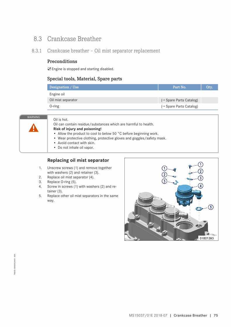
8.3 Crankcase Breather
8.3.1 Crankcase breather – Oil mist separator replacement
Preconditions☑Engine is stopped and starting disabled.
Special tools, Material, Spare partsDesignation / Use Part No. Qty.
Engine oilOil mist separator (→ Spare Parts Catalog)O-ring (→ Spare Parts Catalog)
WARNINGOil is hot.Oil can contain residue/substances which are harmful to health.Risk of injury and poisoning!• Allow the product to cool to below 50 °C before beginning work.• Wear protective clothing, protective gloves and goggles/safety mask.• Avoid contact with skin.• Do not inhale oil vapor.
Replacing oil mist separator1. Unscrew screws (1) and remove together
with washers (2) and retainer (3).2. Replace oil mist separator (4).3. Replace O-ring (5).4. Screw in screws (1) with washers (2) and re-
tainer (3).5. Replace other oil mist separators in the same
way.
MS15037/01E 2018-07 | Crankcase Breather | 75
TIM
-ID: 0
0000
5344
9 - 0
05

8.4 Fan Drive
8.4.1 Drive belt – Condition check
Preconditions☑Engine is stopped and starting disabled.
☑Guard is removed.
Drive belt – Condition check
Item Findings ActionDrive belt A Singular cracks NoneDrive belt B Cracks on entire circumference Replace (→ Page 80)Drive belt C ChunkingDrive belt Belt is oily, shows signs of over-
heating
76 | Fan Drive | MS15037/01E 2018-07
TIM
-ID: 0
0000
6105
0 - 0
02

8.4.2 Drive belt – Tension check
Preconditions☑Engine is stopped and starting disabled.
Special tools, Material, Spare partsDesignation / Use Part No. Qty.
Test device Y4345711 1Preload gauge, 150–600 N Y20097429 1
Measuring belt tension with frequency meter1. Remove protective cover.2. Tap against the belt with the handle of a hammer or with a wrench to initiate belt vibration.3. Hold measuring tip of the frequency meter over belt drive.4. The measured frequency value appears on the display of the frequency meter.5. Compare measured value with value in the table.6. If the measured values deviate from the specified values, adjust drive belt tension (→ Page 79).7. Install protective cover.
Belt length ‒ Application Measured valueInitial installation (new belt)
Measured valueOperating tension (used belt)
Drive belt 1800 mm – Fan Frequency: 88 ±1 Hz Frequency: 77 ±1 HzDrive belt 1520 mm – Fan Frequency: 104 ±1 Hz Frequency: 92 ±1 Hz
Table 7: Specified values ‒ Measurement with frequency meter
Measuring depression depth with preload gaugeNote: The frequency measurement procedure is the preferred one because it provides more exact measurement
results.1. Remove protective cover.
2. Set preload gauge onto the drive belt in themiddle between the belt pulleys (arrowed).
3. Using pushbutton, press vertically on top ofdrive belt exerting even pressure until springcan be heard or felt to engage.
4. Do not exert any more pressure as displayedvalue will otherwise be falsified.
5. Remove preload gauge without changing theposition of the display arm.
6. Read off measured value at the intersectionof display arm and “KG” scale. Refer to tablebelow for set-point value.
7. If the measured values deviate from thespecified values, adjust drive belt tension(→ Page 79).
8. Install protective cover.
MS15037/01E 2018-07 | Fan Drive | 77
TIM
-ID: 0
0000
5348
9 - 0
04

Belt length ‒ Application Measured valueInitial installation (new belt,runtime 0.5-2 h)
Measured value(used belt, runtime 500 h)
Drive belt 1800 mm – Fan Depression depth: 7 mmTest force: 188 N
Depression depth: 8 mmTest force: 188 N
Drive belt 1520 mm – Fan Depression depth: 6 mmTest force: 188 N
Depression depth: 7 mmTest force: 188 N
Table 8: Specified values ‒ Measurement with preload gauge
78 | Fan Drive | MS15037/01E 2018-07
TIM
-ID: 0
0000
5348
9 - 0
04

8.4.3 Drive belt ‒ Tension adjustment
Preconditions☑Engine is stopped and starting disabled.
Special tools, Material, Spare partsDesignation / Use Part No. Qty.
Torque wrench, 20–100 Nm F30026582 1Ratchet bit F30027340 1Torque wrench, 40–200 Nm F30027337 1Ring socket, 24 mm F30501562 1Engine oil
Drive belt ‒ Tension adjustment1. Remove protective cover from cooler.2. Remove protective grill from fan.3. Loosen screws (2) slightly.4. Adjust belt tension as per specifications with
screw (1) (→ Page 77).
5. Tighten screws (2) to specified torque using a torque wrench.
Name Size Type Lubricant Value/Standard
Screw M16 x 50 Tightening torque (Engine oil) 180 Nm +18 Nm
6. Tighten screw (1) to specified torque using a torque wrench.
Name Size Type Lubricant Value/Standard
Screw M16 x200
Tightening torque (Engine oil) 50 Nm +5 Nm
7. Install protective grill on fan (→ Vehicle/plant manufacturer's tightening specifications).8. Install protective cover on cooler (→ Vehicle/plant manufacturer's tightening specifications).
MS15037/01E 2018-07 | Fan Drive | 79
TIM
-ID: 0
0000
5349
0 - 0
03

8.4.4 Drive belt – Replacement
Preconditions☑Engine is stopped and starting disabled.
Special tools, Material, Spare partsDesignation / Use Part No. Qty.
Ring socket, 24 mm F30501562 1Drive belt (→ Spare Parts Catalog)
Replacing fan drive belt1. Remove protective cover from cooler.2. Remove protective grill from fan.3. Remove fan.4. Slacken off securing screws (2).5. Screw out screw (1) until drive belt can be re-
moved.6. Check belt pulley on cooler bearing mount
and crankshaft for contamination and cleanas necessary.
Note: When placing the drive belt in the grooves, noforce must be applied.
7. Fit new drive belt.8. Adjust drive belt tension (→ Page 79).9. Install fan (→ Vehicle/plant manufacturer's
tightening specifications).10. Install protective grill on fan (→ Vehicle/plant
manufacturer's tightening specifications).11. Install protective cover on cooler (→ Vehicle/
plant manufacturer's tightening specifica-tions).
80 | Fan Drive | MS15037/01E 2018-07
TIM
-ID: 0
0000
5475
4 - 0
03

8.5 Valve Drive
8.5.1 Valve clearance – Check and adjustment
Preconditions☑Engine is stopped and starting disabled.
☑Engine coolant temperature is max. 40 °C.
☑Valves are closed.
Special tools, Material, Spare partsDesignation / Use Part No. Qty.
Valve clearance gauge Y4345893 1Barring tool F6792910 1Ratchet with extension F30006212 1Double-end box wrench F30002800 1Offset screwdriver F30453001 1Socket wrench F30030450 1Torque wrench, 20–100 Nm F30026582 1Measuring device Y4348409 1
Preparatory steps1. Install barring device (→ Page 68).2. Remove cylinder head cover (→ Page 83).
Move piston of cylinder A1 intoTDC position (without markingon flywheel)
Note: With cylinder head and valve gear installed.1. Insert preloaded dial gauge (2) into measur-
ing device (4) and clamp using screw (1).2. Install measuring device (4) in cylinder head
and secure using knurled screw (3).3. Zero dial gauge (2).4. Turn engine using barring device until piston
A1 reaches firing TDC.Result: The piston is at firing TDC when both rocker
arms are unloaded, i.e. have clearance.
Move piston of cylinder A1 into TDC position (without marking on flywheel)1. Unscrew plug screw on B-side of flywheel housing.2. Bar engine in direction of rotation until marking on flywheel is visible in the middle.
Result: The piston is at firing TDC when both rocker arms are unloaded, i.e. have clearance.
MS15037/01E 2018-07 | Valve Drive | 81
TIM
-ID: 0
0000
8014
2 - 0
01
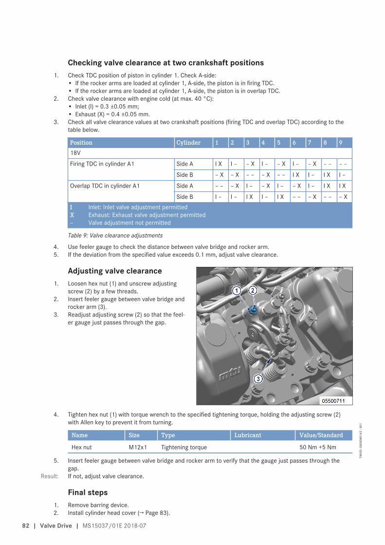
Checking valve clearance at two crankshaft positions1. Check TDC position of piston in cylinder 1. Check A-side:
• If the rocker arms are loaded at cylinder 1, A-side, the piston is in firing TDC.• If the rocker arms are loaded at cylinder 1, A-side, the piston is in overlap TDC.
2. Check valve clearance with engine cold (at max. 40 °C):• Inlet (I) = 0.3 ±0.05 mm;• Exhaust (X) = 0.4 ±0.05 mm.
3. Check all valve clearance values at two crankshaft positions (firing TDC and overlap TDC) according to thetable below.
Position Cylinder 1 2 3 4 5 6 7 8 918V
Firing TDC in cylinder A1 Side A I X I – – X I – – X I – – X – – – –
Side B – X – X – – – X – – I X I – I X I –
Overlap TDC in cylinder A1 Side A – – – X I – – X I – – X I – I X I X
Side B I – I – I X I – I X – – – X – – – XI Inlet: Inlet valve adjustment permittedX Exhaust: Exhaust valve adjustment permitted– Valve adjustment not permitted
Table 9: Valve clearance adjustments
4. Use feeler gauge to check the distance between valve bridge and rocker arm.5. If the deviation from the specified value exceeds 0.1 mm, adjust valve clearance.
Adjusting valve clearance1. Loosen hex nut (1) and unscrew adjusting
screw (2) by a few threads.2. Insert feeler gauge between valve bridge and
rocker arm (3).3. Readjust adjusting screw (2) so that the feel-
er gauge just passes through the gap.
4. Tighten hex nut (1) with torque wrench to the specified tightening torque, holding the adjusting screw (2)with Allen key to prevent it from turning.
Name Size Type Lubricant Value/Standard
Hex nut M12x1 Tightening torque 50 Nm +5 Nm
5. Insert feeler gauge between valve bridge and rocker arm to verify that the gauge just passes through thegap.
Result: If not, adjust valve clearance.
Final steps1. Remove barring device.2. Install cylinder head cover (→ Page 83).
82 | Valve Drive | MS15037/01E 2018-07
TIM
-ID: 0
0000
8014
2 - 0
01

8.5.2 Cylinder head cover – Cylinder head cover
Preconditions☑Engine is stopped and starting disabled.
Special tools, Material, Spare partsDesignation / Use Part No. Qty.
Torque wrench, 8–40 Nm F30043446 1Torque wrench, 0.5–5 Nm 0015384230 1Ratchet bit F30027340 1Engine oilSeal (→ Spare Parts Catalog)
Preparatory steps1. Open wiring harness safety clips on cylinder head cover.2. Disconnect wiring harness.
Removing and installing cylin-der head cover
1. Remove cylinder head cover (2) from cylinderhead.
2. Disconnect terminals (arrowed) on injectorand pull out cable lugs.
3. Clean mating face.
MS15037/01E 2018-07 | Valve Drive | 83
TIM
-ID: 0
0000
5345
2 - 0
03

4. Check condition of gasket (1).5. Replace gasket (1) if damaged.6. Place gasket (1) in correct position on cylin-
der head.
7. Push spade lugs under the terminals on the injector and tighten to specified torque using a torque wrench.
Name Size Type Lubricant Value/Standard
Nut M4 Tightening torque (Engine oil) 1.5 Nm ±0.25 Nm
8. Install cylinder head cover (2) with screws (4) and washer (3).
Final steps1. Connect wiring harness.2. Close wiring harness safety clips on cylinder head cover.
84 | Valve Drive | MS15037/01E 2018-07
TIM
-ID: 0
0000
5345
2 - 0
03

8.6 Injection Valve / Injector
8.6.1 Injector ‒ Replacement
Special tools, Material, Spare partsDesignation / Use Part No. Qty.
Injector (→ Spare Parts Catalog)Screw for hold-down clamp (→ Spare Parts Catalog)
Replacing injectoru Remove injector and install new one (→ Page 86).
MS15037/01E 2018-07 | Injection Valve / Injector | 85
TIM
-ID: 0
0000
5345
3 - 0
01

8.6.2 Injector – Removal and installation
Preconditions☑Engine is stopped and starting disabled.
Special tools, Material, Spare partsDesignation / Use Part No. Qty.
Press-in tool F6790085 1Extraction device F6790636 1Fuel suction pipe F30378207 1Torque wrench, 20–100 Nm F30026582 1Torque wrench, 0.5–5 Nm 0015384230 1Ratchet bit F30027340 1Plug-in open-end wrench, 19 mm F30453236 1Crowfoot wrench, 19 mm F30027424 1Ring socket, 22 mm F30038494 1Double-head box wrench F30011450 1Socket wrench, 24 mm F30453238 1Assembly compound (Kluthe Hakuform 30-15) X00067260 1Engine oilSealing ring (→ Spare Parts Catalog)
WARNINGFuels are combustible and explosive.Risk of fire and explosion!• Avoid open flames, electrical sparks and ignition sources.• Do not smoke.• Wear protective clothing, protective gloves, and safety glasses / facial protection.
WARNINGResidual pressure in high-pressure fuel system.Risk of injury from fuel escaping under high pressure!• After an emergency stop or engine stall, energize the engine governor for approx. 30 s.• Always wear protective gloves and protective goggles/safety mask.• Loosen threaded connections slowly.
WARNINGInternal tension and residual pressure in the HP fuel system.Parts can be ejected when loosening them.Risk of injury by ejected parts!• Only use specified tools and devices.• Wear goggles/facial protection.
WARNINGLiquid or gaseous media, e.g. fuel, are poisonous.Escaping vapors of highly volatile media, e.g. fuel or ether.Risk of fatal injury through swallowing; risk of poisoning through inhalation; irritation to eyesand skin!• Seek medical attention immediately; do not induce vomiting.• Do not inhale vapors or mist.• Wear protective clothing, protective gloves, and safety glasses.• If contact is made with skin, wash off with water and soap.
86 | Injection Valve / Injector | MS15037/01E 2018-07
TIM
-ID: 0
0000
5090
9 - 0
10

WARNINGCompressed air gun ejects a jet of pressurized air.Risk of injury to eyes and damage to hearing, risk of rupturing internal organs!• Never direct air jet at people.• Always wear safety goggles/face mask and ear defenders.
Preparatory steps1. Close fuel supply line.2. Remove cylinder head cover (→ Page 83).
Removing pressure pipe neck1. Remove HP fuel line (1).2. Unscrew union nut (2).3. Pull off pressure pipe neck (3).4. Extract fuel from the exposed bores using the
suction device.
Removing injector1. Remove screw (3).2. Take off hold-down clamp (2).3. Use the puller to pull out injector (1).4. After removal, seal all openings with suitable
covers.
MS15037/01E 2018-07 | Injection Valve / Injector | 87
TIM
-ID: 0
0000
5090
9 - 0
10
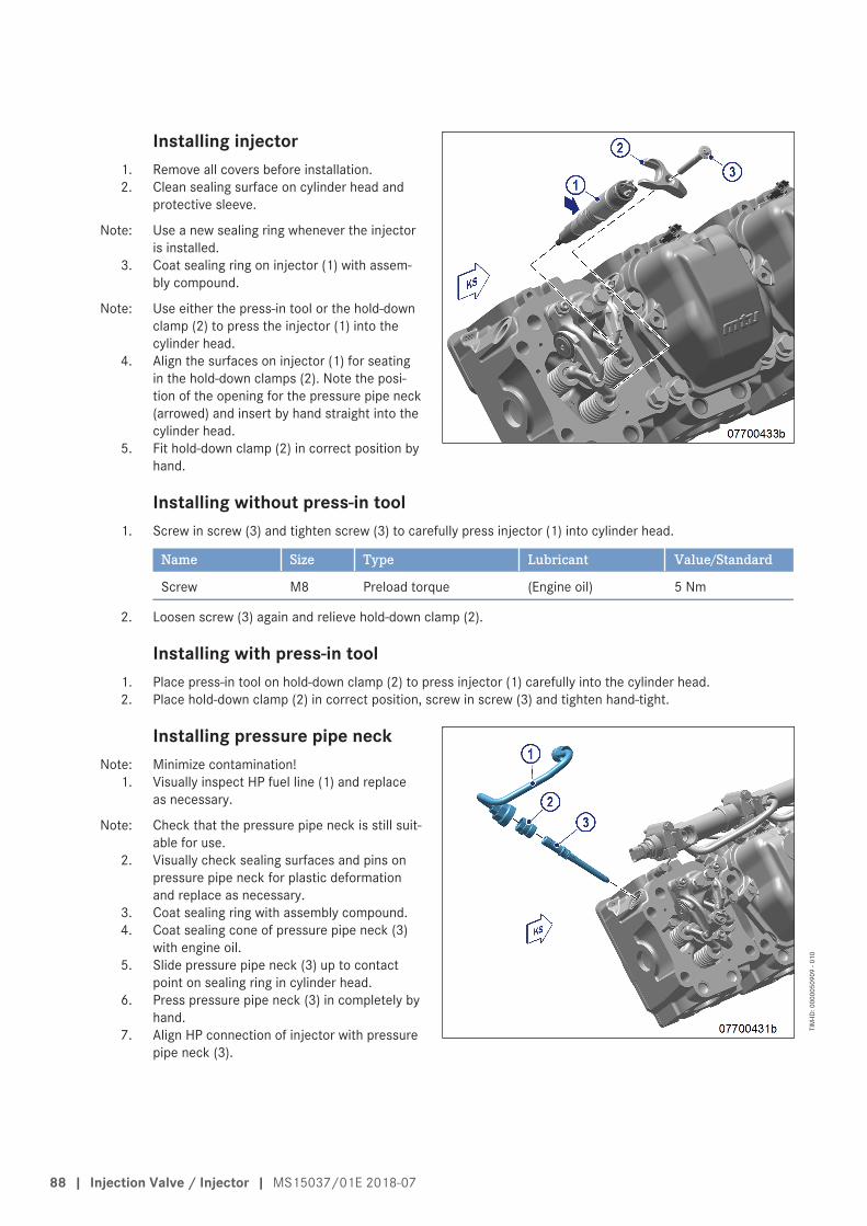
Installing injector1. Remove all covers before installation.2. Clean sealing surface on cylinder head and
protective sleeve.
Note: Use a new sealing ring whenever the injectoris installed.
3. Coat sealing ring on injector (1) with assem-bly compound.
Note: Use either the press-in tool or the hold-downclamp (2) to press the injector (1) into thecylinder head.
4. Align the surfaces on injector (1) for seatingin the hold-down clamps (2). Note the posi-tion of the opening for the pressure pipe neck(arrowed) and insert by hand straight into thecylinder head.
5. Fit hold-down clamp (2) in correct position byhand.
Installing without press-in tool1. Screw in screw (3) and tighten screw (3) to carefully press injector (1) into cylinder head.
Name Size Type Lubricant Value/Standard
Screw M8 Preload torque (Engine oil) 5 Nm
2. Loosen screw (3) again and relieve hold-down clamp (2).
Installing with press-in tool1. Place press-in tool on hold-down clamp (2) to press injector (1) carefully into the cylinder head.2. Place hold-down clamp (2) in correct position, screw in screw (3) and tighten hand-tight.
Installing pressure pipe neckNote: Minimize contamination!
1. Visually inspect HP fuel line (1) and replaceas necessary.
Note: Check that the pressure pipe neck is still suit-able for use.
2. Visually check sealing surfaces and pins onpressure pipe neck for plastic deformationand replace as necessary.
3. Coat sealing ring with assembly compound.4. Coat sealing cone of pressure pipe neck (3)
with engine oil.5. Slide pressure pipe neck (3) up to contact
point on sealing ring in cylinder head.6. Press pressure pipe neck (3) in completely by
hand.7. Align HP connection of injector with pressure
pipe neck (3).
88 | Injection Valve / Injector | MS15037/01E 2018-07
TIM
-ID: 0
0000
5090
9 - 0
10

8. Coat thread and shoulder of union nut (2) with engine oil and tighten to specified torque using a torquewrench.
Name Size Type Lubricant Value/Standard
Union nut M24 Preload torque (Engine oil) 15 Nm +5 Nm
9. Tighten screw (3) for hold-down clamp (2) to specified torque using a torque wrench.
Name Size Type Lubricant Value/Standard
Screw M8 Tightening torque (Engine oil) 40 Nm +4 Nm
10. Tighten union nut (2) on pressure pipe neck (3) to specified torque using a torque wrench.
Name Size Type Lubricant Value/Standard
Union nut M24 Tightening torque 50 Nm +5 Nm
MS15037/01E 2018-07 | Injection Valve / Injector | 89
TIM
-ID: 0
0000
5090
9 - 0
10

Installing fuel line1. Coat thread and shoulder of union nuts on HP fuel line (1) with engine oil.
Note: Position fuel line, ensuring it is free of tension.2. Position HP fuel line (1) with union nut (2) in correct position between rail and pressure pipe neck (3), then
tighten by hand.
3. Tighten union nut of HP fuel line (1) on rail to specified torque using a torque wrench.a) In case of single-wall HP fuel system
Name Size Type Lubricant Value/Standard
Union nut M20 Tightening torque (Engine oil) 37 Nm +3 Nm
b) In case of double-wall (jacketed) HP fuel system
Name Size Type Lubricant Value/Standard
Union nut M20 Tightening torque (Engine oil) 50 Nm +5 Nm
4. Tighten union nut of HP fuel line (1) on pressure pipe neck (3) to specified torque using a torque wrench.
Name Size Type Lubricant Value/Standard
Union nut M16 Tightening torque (Engine oil) 37 Nm +3 Nm
Final steps1. Install cylinder head cover (→ Page 83).2. Open fuel supply line.3. Vent fuel system (→ Page 94).
90 | Injection Valve / Injector | MS15037/01E 2018-07
TIM
-ID: 0
0000
5090
9 - 0
10

8.6.3 Injector functions
Preconditions☑Engine is stopped and starting disabled.
Note: Failure to reset the drift correction parameters (CDC) and enter injector coding will render the emissions cer-tification of the engine null and void.
Resetting drift correction parameters (CDC) with DiaSys®Note: Document can be found on the service PC in C:\DiaSys\Doku after successful installation of DiaSys®.
1. (→ Dialog system DiaSys® E531920/..).2. If no DiaSys® is available, contact Service.
Entering injector coding (IIG)Note: Document can be found on the service PC in C:\DiaSys\Doku after successful installation of DiaSys®.
1. (→ Dialog system DiaSys® E531920/..).2. If no DiaSys® is available, contact Service.
MS15037/01E 2018-07 | Injection Valve / Injector | 91
TIM
-ID: 0
0000
4542
5 - 0
03

8.7 Fuel System
8.7.1 HP fuel line and pressure pipe neck – Replacement
Preconditions☑Engine is stopped and starting disabled.
Special tools, Material, Spare partsDesignation / Use Part No. Qty.
Torque wrench, 20–100 Nm F30026582 1Ratchet bit F30027340 1Plug-in open-end wrench, 19 mm F30025897 1Crowfoot wrench, 19 mm F30027424 1Ring socket, 24 mm F30501562 1Double-head box wrench F30011450 1Assembly compound (Kluthe Hakuform 30–15) X00067260 1Engine oilPressure pipe neck (→ Spare Parts Catalog)HP fuel line (→ Spare Parts Catalog)Seal (→ Spare Parts Catalog)
WARNINGFuels are combustible and explosive.Risk of fire and explosion!• Avoid open flames, electrical sparks and ignition sources.• Do not smoke.• Wear protective clothing, protective gloves, and safety glasses / facial protection.
WARNINGResidual pressure in high-pressure fuel system.Risk of injury from fuel escaping under high pressure!• After an emergency stop or engine stall, energize the engine governor for approx. 30 s.• Always wear protective gloves and protective goggles/safety mask.• Loosen threaded connections slowly.
WARNINGInternal tension and residual pressure in the HP fuel system.Parts can be ejected when loosening them.Risk of injury by ejected parts!• Only use specified tools and devices.• Wear goggles/facial protection.
WARNINGLiquid or gaseous media, e.g. fuel, are poisonous.Escaping vapors of highly volatile media, e.g. fuel or ether.Risk of fatal injury through swallowing; risk of poisoning through inhalation; irritation to eyesand skin!• Seek medical attention immediately; do not induce vomiting.• Do not inhale vapors or mist.• Wear protective clothing, protective gloves, and safety glasses.• If contact is made with skin, wash off with water and soap.
92 | Fuel System | MS15037/01E 2018-07
TIM
-ID: 0
0000
7916
6 - 0
02
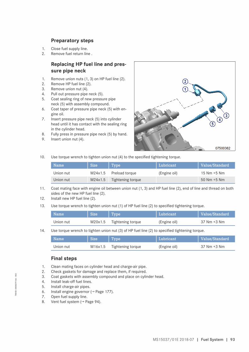
Preparatory steps1. Close fuel supply line.2. Remove fuel return line .
Replacing HP fuel line and pres-sure pipe neck
1. Remove union nuts (1, 3) on HP fuel line (2).2. Remove HP fuel line (2).3. Remove union nut (4).4. Pull out pressure pipe neck (5).5. Coat sealing ring of new pressure pipe
neck (5) with assembly compound.6. Coat taper of pressure pipe neck (5) with en-
gine oil.7. Insert pressure pipe neck (5) into cylinder
head until it has contact with the sealing ringin the cylinder head.
8. Fully press in pressure pipe neck (5) by hand.9. Insert union nut (4).
10. Use torque wrench to tighten union nut (4) to the specified tightening torque.
Name Size Type Lubricant Value/Standard
Union nut M24x1.5 Preload torque (Engine oil) 15 Nm +5 NmUnion nut M24x1.5 Tightening torque 50 Nm +5 Nm
11. Coat mating face with engine oil between union nut (1, 3) and HP fuel line (2), end of line and thread on bothsides of the new HP fuel line (2).
12. Install new HP fuel line (2).
13. Use torque wrench to tighten union nut (1) of HP fuel line (2) to specified tightening torque.
Name Size Type Lubricant Value/Standard
Union nut M20x1.5 Tightening torque (Engine oil) 37 Nm +3 Nm
14. Use torque wrench to tighten union nut (3) of HP fuel line (2) to specified tightening torque.
Name Size Type Lubricant Value/Standard
Union nut M16x1.5 Tightening torque (Engine oil) 37 Nm +3 Nm
Final steps1. Clean mating faces on cylinder head and charge-air pipe.2. Check gaskets for damage and replace them, if required.3. Coat gaskets with assembly compound and place on cylinder head.4. Install leak-off fuel lines.5. Install charge-air pipes.6. Install engine governor (→ Page 177).7. Open fuel supply line.8. Vent fuel system (→ Page 94).
MS15037/01E 2018-07 | Fuel System | 93
TIM
-ID: 0
0000
7916
6 - 0
02

8.7.2 Fuel system – Venting
Preconditions☑Engine is stopped and starting disabled.
☑Engine is cooled down to ambient temperature.
Special tools, Material, Spare partsDesignation / Use Part No. Qty.
Torque wrench, 8–40 Nm F30043446 1Ring socket, 22 mm F30038494 1
WARNINGFuels are combustible and explosive.Risk of fire and explosion!• Avoid open flames, electrical sparks and ignition sources.• Do not smoke.• Wear protective clothing, protective gloves, and safety glasses / facial protection.
Fuel system – Venting1. Open the unpressurized return to the tank (2)
and connect to the tank or a suitably largevessel.
2. Open vent valve (3) on fuel filter.3. Vent fuel filter by actuating hand pump (1).
4. Close vent valve (3) on fuel filter and tighten to specified tightening torque.
Name Size Type Lubricant Value/Standard
Threaded vent plug M14 Tightening torque 15 Nm +4 Nm
5. Actuate hand pump (1) until HP pump flow can be heard. Fuel emerges from the return to the tank (2) now.6. Connect return to tank (2).7. Start the engine.
94 | Fuel System | MS15037/01E 2018-07
TIM
-ID: 0
0000
7717
6 - 0
02

8.7.3 Fuel – Draining
Preconditions☑Engine is stopped and starting disabled.
WARNINGFuels are combustible and explosive.Risk of fire and explosion!• Avoid open flames, electrical sparks and ignition sources.• Do not smoke.• Wear protective clothing, protective gloves, and safety glasses / facial protection.
WARNINGLiquid or gaseous media, e.g. fuel, are poisonous.Escaping vapors of highly volatile media, e.g. fuel or ether.Risk of fatal injury through swallowing; risk of poisoning through inhalation; irritation to eyesand skin!• Seek medical attention immediately; do not induce vomiting.• Do not inhale vapors or mist.• Wear protective clothing, protective gloves, and safety glasses.• If contact is made with skin, wash off with water and soap.
Fuel – Draining1. Provide a suitable container in which to collect the fuel.2. Remove fuel filter (→ Page 99).3. Catch fuel as it runs out.4. Install fuel filter (→ Page 99).
MS15037/01E 2018-07 | Fuel System | 95
TIM
-ID: 0
0000
0470
2 - 0
05

8.7.4 Fuel cooler – External contamination and leak-tightness check
Preconditions☑Engine is stopped and starting disabled.
☑All fuel cooler power sources are disconnected.
WARNINGFuels are combustible and explosive.Risk of fire and explosion!• Avoid open flames, electrical sparks and ignition sources.• Do not smoke.• Wear protective clothing, protective gloves, and safety glasses / facial protection.
WARNINGHot components/surfaces.Risk of burns!• Allow the engine to cool down to below 50 °C before beginning work.• Wear suitable protective equipment/thermal gloves.• Avoid unprotected contact with hot surfaces.
WARNINGLiquid or gaseous media, e.g. fuel, are poisonous.Escaping vapors of highly volatile media, e.g. fuel or ether.Risk of fatal injury through swallowing; risk of poisoning through inhalation; irritation to eyesand skin!• Seek medical attention immediately; do not induce vomiting.• Do not inhale vapors or mist.• Wear protective clothing, protective gloves, and safety glasses.• If contact is made with skin, wash off with water and soap.
Fuel cooler – External contamination and leak-tightness checkElement Findings ActionCheck fuel cooler and connectionsfor leakage.
Leakage Contact Service.
Check housing and fuel coolerelectric motor for dust and foreignobjects.
Dust and/or foreign objects Clean fan guard with a soft brush.Clean surface of fuel cooler with adamp rag.Clean fuel cooler if heavily conta-minated (→ Page 97).
96 | Fuel System | MS15037/01E 2018-07
TIM
-ID: 0
0000
8175
3 - 0
01

8.7.5 Fuel cooler – Cleaning
Preconditions☑Engine is stopped and starting disabled.
☑All fuel cooler power sources are disconnected.
WARNINGHot components/surfaces.Risk of burns!• Allow the engine to cool down to below 50 °C before beginning work.• Wear suitable protective equipment/thermal gloves.• Avoid unprotected contact with hot surfaces.
WARNINGFuels are combustible and explosive.Risk of fire and explosion!• Avoid open flames, electrical sparks and ignition sources.• Do not smoke.• Wear protective clothing, protective gloves, and safety glasses / facial protection.
WARNINGLiquid or gaseous media, e.g. fuel, are poisonous.Escaping vapors of highly volatile media, e.g. fuel or ether.Risk of fatal injury through swallowing; risk of poisoning through inhalation; irritation to eyesand skin!• Seek medical attention immediately; do not induce vomiting.• Do not inhale vapors or mist.• Wear protective clothing, protective gloves, and safety glasses.• If contact is made with skin, wash off with water and soap.
WARNINGCompressed air gun ejects a jet of pressurized air.Risk of injury to eyes and damage to hearing, risk of rupturing internal organs!• Never direct air jet at people.• Always wear safety goggles/face mask and ear defenders.
WARNINGChemical substances in cleaners.Risk of irritation and chemical burns!• Always obey manufacturer's instructions for use.
NOTICECleaning agents should not be left to take effect for too long.Damage to components is possible!• Observe manufacturer's instructions.
NOTICEInappropriate cleaning tool.Risk of damage to component!• Observe manufacturer's instructions.• Use appropriate cleaning tool.
MS15037/01E 2018-07 | Fuel System | 97
TIM
-ID: 0
0000
8175
4 - 0
02

Cleaning with a compressed-air pistol1. Blow out cooler elements with a jet of compressed air working against the direction of the cooling air parallel
to the cooling fins.2. Remove and dispose of dirt before putting engine into operation.3. Use industrial high-pressure cleaner to clean fuel cooler in case of stubborn contamination.
Cleaning with industrial high-pressure cleanerNote: • To avoid damage to cooling elements, only aim water jet parallel to the cooling fins applying moderate
pressure.• To improve the cleaning effect, add a suitable degreasing agent to the water (in accordance with the rec-
ommendations of the high-pressure cleaner manufacturer). The degreasing agent must be approved forlight metal containing coolers.
1. Use high-pressure cleaner to clean cooling elements working against the direction of the cooling air.2. Thoroughly dry cooler and surrounding areas before putting engine into operation.
98 | Fuel System | MS15037/01E 2018-07
TIM
-ID: 0
0000
8175
4 - 0
02

8.8 Fuel Filter
8.8.1 Fuel filter – Replacement
Preconditions☑Engine is stopped and starting disabled.
Special tools, Material, Spare partsDesignation / Use Part No. Qty.
Filter wrench F30379104 1Easy-change filter (→ Spare Parts Catalog)
WARNINGFuels are combustible and explosive.Risk of fire and explosion!• Avoid open flames, electrical sparks and ignition sources.• Do not smoke.• Wear protective clothing, protective gloves, and safety glasses / facial protection.
WARNINGLiquid or gaseous media, e.g. fuel, are poisonous.Escaping vapors of highly volatile media, e.g. fuel or ether.Risk of fatal injury through swallowing; risk of poisoning through inhalation; irritation to eyesand skin!• Seek medical attention immediately; do not induce vomiting.• Do not inhale vapors or mist.• Wear protective clothing, protective gloves, and safety glasses.• If contact is made with skin, wash off with water and soap.
Fuel filter – Replacement1. Remove easy-change filter (3) with filter
wrench.2. Clean sealing surface on retainer (1).3. Apply a thin layer of oil to the seal (2) on the
easy-change filter.4. Install and tighten easy-change filter by hand.5. Replace further easy-change filters in the
same way.6. Vent fuel system (→ Page 94).
MS15037/01E 2018-07 | Fuel Filter | 99
TIM
-ID: 0
0000
5345
4 - 0
05

8.8.2 Fuel prefilter – Draining
Fuel prefilter (non-switchable)u Drain water and contaminants from fuel prefilter (→ Page 101).
Fuel prefilter (switchable)u Drain water and contaminants from fuel prefilter (→ Page 103).
100 | Fuel Filter | MS15037/01E 2018-07
TIM
-ID: 0
0000
5815
1 - 0
04
8.8.3 Fuel prefilter (non-switchable) – Draining
DANGERComponents are moving or rotating.Risk of crushing, danger of parts of the body being caught or pulled in!• Operate the engine at low load only. Keep clear of the danger zone of the engine.
WARNINGFuels are combustible and explosive.Risk of fire and explosion!• Avoid open flames, electrical sparks and ignition sources.• Do not smoke.• Wear protective clothing, protective gloves, and safety glasses / facial protection.
WARNINGLiquid or gaseous media, e.g. fuel, are poisonous.Escaping vapors of highly volatile media, e.g. fuel or ether.Risk of fatal injury through swallowing; risk of poisoning through inhalation; irritation to eyesand skin!• Seek medical attention immediately; do not induce vomiting.• Do not inhale vapors or mist.• Wear protective clothing, protective gloves, and safety glasses.• If contact is made with skin, wash off with water and soap.
WARNINGExhaust gases are harmful to health and may cause cancer.Risk of poisoning and suffocation!• Keep the engine room well-ventilated at all times.• Repair leaking exhaust pipework immediately.
WARNINGHigh level of engine noise when the engine is running.Risk of damage to hearing!• Wear ear protectors.
WARNINGFuel in the prefilter can be pressurized.Risk of injury through spraying fuel!• Wear protective gloves and eye protectors/safety mask.• Open screw-coupling slowly.
Preparatory stepsu Pressure ratios in the fuel prefilter, see (→ Page 106).
• In case of low pressure, drain fuel prefilter according to version A, see (→ Page 101).• In case of high pressure, drain fuel prefilter according to version B, see (→ Page 102).
Draining fuel prefilter with low pressure, version ANote: The fuel prefilter must only be drained with the engine at a standstill!
1. Provide a suitable container to collect the water.2. Stop engine and disable engine start.3. Close fuel supply if a shutoff valve is available.
MS15037/01E 2018-07 | Fuel Filter | 101
TIM
-ID: 0
0000
6642
8 - 0
05
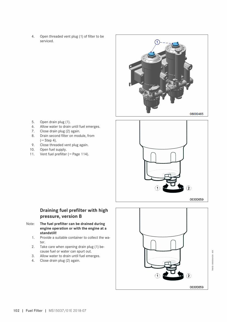
4. Open threaded vent plug (1) of filter to beserviced.
5. Open drain plug (1).6. Allow water to drain until fuel emerges.7. Close drain plug (2) again.8. Drain second filter on module, from
(→ Step 4).9. Close threaded vent plug again.
10. Open fuel supply.11. Vent fuel prefilter (→ Page 114).
Draining fuel prefilter with highpressure, version B
Note: The fuel prefilter can be drained duringengine operation or with the engine at astandstill!
1. Provide a suitable container to collect the wa-ter.
2. Take care when opening drain plug (1) be-cause fuel or water can spurt out.
3. Allow water to drain until fuel emerges.4. Close drain plug (2) again.
102 | Fuel Filter | MS15037/01E 2018-07
TIM
-ID: 0
0000
6642
8 - 0
05
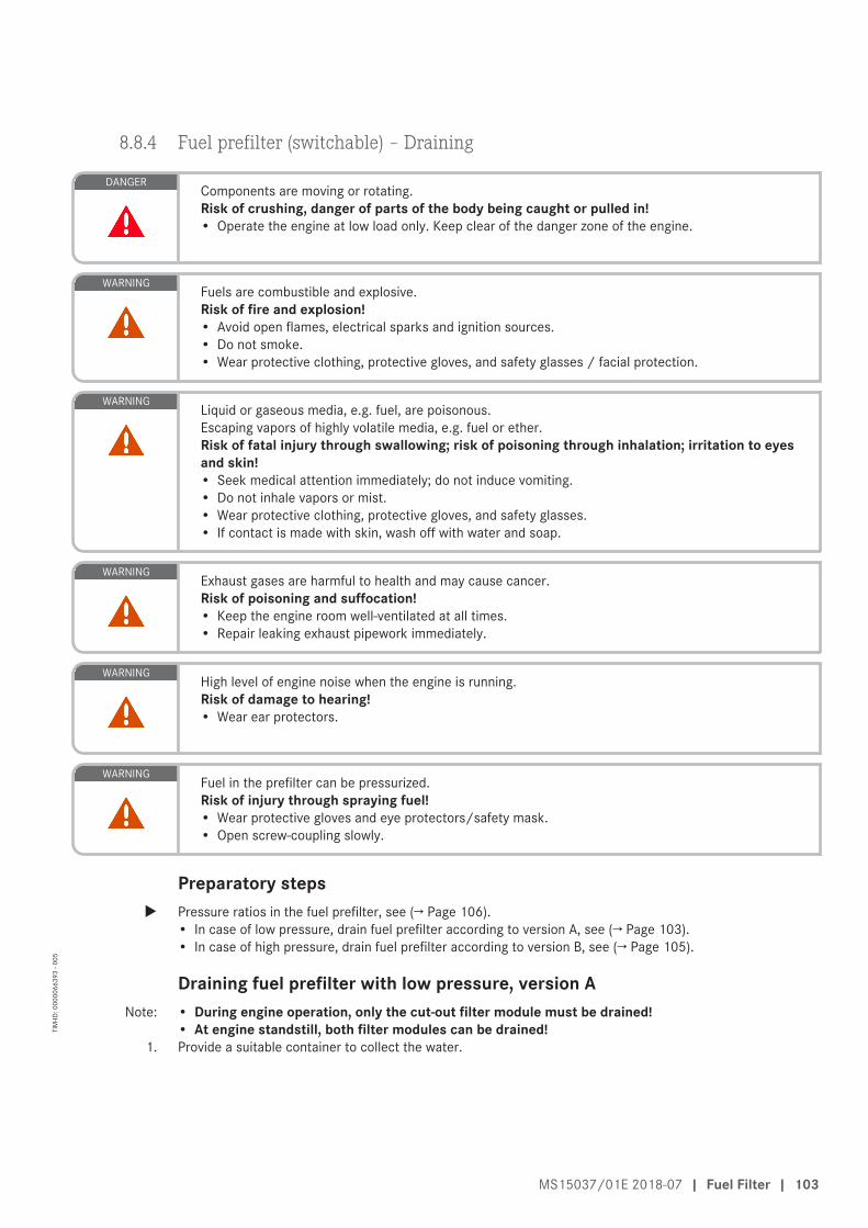
8.8.4 Fuel prefilter (switchable) – Draining
DANGERComponents are moving or rotating.Risk of crushing, danger of parts of the body being caught or pulled in!• Operate the engine at low load only. Keep clear of the danger zone of the engine.
WARNINGFuels are combustible and explosive.Risk of fire and explosion!• Avoid open flames, electrical sparks and ignition sources.• Do not smoke.• Wear protective clothing, protective gloves, and safety glasses / facial protection.
WARNINGLiquid or gaseous media, e.g. fuel, are poisonous.Escaping vapors of highly volatile media, e.g. fuel or ether.Risk of fatal injury through swallowing; risk of poisoning through inhalation; irritation to eyesand skin!• Seek medical attention immediately; do not induce vomiting.• Do not inhale vapors or mist.• Wear protective clothing, protective gloves, and safety glasses.• If contact is made with skin, wash off with water and soap.
WARNINGExhaust gases are harmful to health and may cause cancer.Risk of poisoning and suffocation!• Keep the engine room well-ventilated at all times.• Repair leaking exhaust pipework immediately.
WARNINGHigh level of engine noise when the engine is running.Risk of damage to hearing!• Wear ear protectors.
WARNINGFuel in the prefilter can be pressurized.Risk of injury through spraying fuel!• Wear protective gloves and eye protectors/safety mask.• Open screw-coupling slowly.
Preparatory stepsu Pressure ratios in the fuel prefilter, see (→ Page 106).
• In case of low pressure, drain fuel prefilter according to version A, see (→ Page 103).• In case of high pressure, drain fuel prefilter according to version B, see (→ Page 105).
Draining fuel prefilter with low pressure, version ANote: • During engine operation, only the cut-out filter module must be drained!
• At engine standstill, both filter modules can be drained!1. Provide a suitable container to collect the water.
MS15037/01E 2018-07 | Fuel Filter | 103
TIM
-ID: 0
0000
6639
3 - 0
05

2. During engine operation, turn the switchoverlevel as far as the stop (arrow) to cut out thefilter module to be serviced.
Result: • Filter module (1) is cut in• Filter module (2) is cut out
3. Open threaded vent plug (1) of filter to beserviced.
4. Open drain plug (1).5. Allow water to drain until fuel emerges.6. Close drain plug (2) again.7. Drain the second filter on the module to be
serviced, from (→ Step 3).8. Close threaded vent plug again.9. Vent fuel prefilter (→ Page 114).
104 | Fuel Filter | MS15037/01E 2018-07
TIM
-ID: 0
0000
6639
3 - 0
05

Draining fuel prefilter with high pressure, version BNote: The filter modules can be drained without switchover during engine operation and at engine stand-
still!1. Provide a suitable container to collect the water.
2. Take care when opening drain plug (1) be-cause fuel or water can spurt out.
3. Allow water to drain until fuel emerges.4. Close drain plug (2) again.
MS15037/01E 2018-07 | Fuel Filter | 105
TIM
-ID: 0
0000
6639
3 - 0
05

8.8.5 Fuel prefilter – Pressure ratios
WARNINGFuels are combustible and explosive.Risk of fire and explosion!• Avoid open flames, electrical sparks and ignition sources.• Do not smoke.• Wear protective clothing, protective gloves, and safety glasses / facial protection.
WARNINGLiquid or gaseous media, e.g. fuel, are poisonous.Escaping vapors of highly volatile media, e.g. fuel or ether.Risk of fatal injury through swallowing; risk of poisoning through inhalation; irritation to eyesand skin!• Seek medical attention immediately; do not induce vomiting.• Do not inhale vapors or mist.• Wear protective clothing, protective gloves, and safety glasses.• If contact is made with skin, wash off with water and soap.
Pressure ratiosNote: • If the fuel prefilter is above the full level of the fuel tank, during engine operation the fuel pressure in the
filter is lower than ambient pressure (vacuum).• If the fuel prefilter is below the empty level of the fuel tank, during engine operation the fuel pressure in
the filter is higher than ambient pressure (overpressure).In the case of overpressure, fuel can escape under pressure.
u The pressure ratios should be known from commissioning. Pressure ratios can be checked with the engineshut down.
Checking pressure ratios1. Stop engine and disable engine start.
2. Carefully open threaded vent plug (1) slightly:Result: • If no fuel emerges, this is an indication of
vacuum or pressure balance.• If fuel emerges, this is a sign of overpres-
sure.3. Collect fuel as it emerges.
106 | Fuel Filter | MS15037/01E 2018-07
TIM
-ID: 0
0000
6672
6 - 0
03

8.8.6 Fuel prefilter (switchable) – Low pressure indicator check
Low pressure indicator onswitchable fuel prefilter
1. Check low pressure indicator reading at lowpressure gauge (3):• Red zone (1): -1.0 bar to -0.4 bar (low
pressure)• Green zone (2): -0.4 bar to +0.5 bar (nor-
mal operation)2. Switch over the fuel prefilter or replace a fil-
ter element (→ Page 111) when the low pres-sure gauge (3) indicates minimum admissiblefuel pressure during operation (1) .
MS15037/01E 2018-07 | Fuel Filter | 107
TIM
-ID: 0
0000
7406
4 - 0
02

8.8.7 Fuel prefilter – Filter element replacement
Fuel prefilter (non-switchable)u Fuel prefilter, replace filter element (→ Page 109).
Fuel prefilter (switchable)u Fuel prefilter, replace filter element (→ Page 111).
108 | Fuel Filter | MS15037/01E 2018-07
TIM
-ID: 0
0000
5814
9 - 0
04
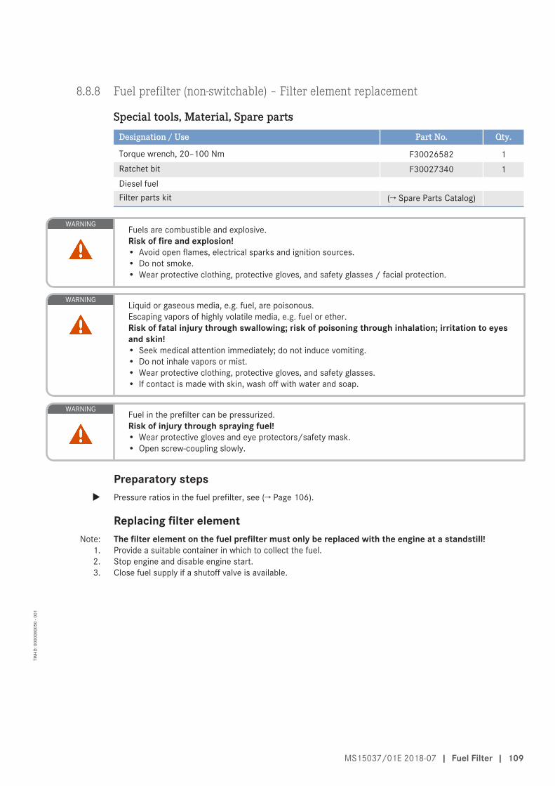
8.8.8 Fuel prefilter (non-switchable) – Filter element replacement
Special tools, Material, Spare partsDesignation / Use Part No. Qty.
Torque wrench, 20–100 Nm F30026582 1Ratchet bit F30027340 1Diesel fuelFilter parts kit (→ Spare Parts Catalog)
WARNINGFuels are combustible and explosive.Risk of fire and explosion!• Avoid open flames, electrical sparks and ignition sources.• Do not smoke.• Wear protective clothing, protective gloves, and safety glasses / facial protection.
WARNINGLiquid or gaseous media, e.g. fuel, are poisonous.Escaping vapors of highly volatile media, e.g. fuel or ether.Risk of fatal injury through swallowing; risk of poisoning through inhalation; irritation to eyesand skin!• Seek medical attention immediately; do not induce vomiting.• Do not inhale vapors or mist.• Wear protective clothing, protective gloves, and safety glasses.• If contact is made with skin, wash off with water and soap.
WARNINGFuel in the prefilter can be pressurized.Risk of injury through spraying fuel!• Wear protective gloves and eye protectors/safety mask.• Open screw-coupling slowly.
Preparatory stepsu Pressure ratios in the fuel prefilter, see (→ Page 106).
Replacing filter elementNote: The filter element on the fuel prefilter must only be replaced with the engine at a standstill!
1. Provide a suitable container in which to collect the fuel.2. Stop engine and disable engine start.3. Close fuel supply if a shutoff valve is available.
MS15037/01E 2018-07 | Fuel Filter | 109
TIM
-ID: 0
0000
8005
0 - 0
01

4. Open threaded vent plug and ensure that fueldoes not emerge continuously.
Result: The filter can now be replaced!5. If fuel emerges continuously, check shutoff
valve in fuel supply, contact Service.
Note: • As soon as the filter housing is opened,absolute cleanness is imperative!
• Carefully extract the filter element straightup avoiding contact with the upper edge ofthe cylinder if at all possible to preventcontamination of the fuel remaining in thefilter housing.
6. Unscrew filter cover (1) and pull it togetherwith filter element (3) out of filter housing (4).
7. Unclip filter element (3) from filter cover (1).8. Install new O-ring (2) on filter cover (1).9. Coat new O-rings on filter cover and filter ele-
ment with fuel.10. Clip new filter element (3) into filter cover (1).11. Screw filter cover (1) into filter housing.
Result: Filter cover (1) must lie flat on the housing(4).
12. Tighten filter cover (1) with torque wrench to the specified tightening torque.
Name Size Type Lubricant Value/Standard
Filter cover Tightening torque 40 Nm
13. Replace second filter element in the same manner.14. Open fuel supply.15. Vent fuel prefilter (→ Page 114).16. Check fuel prefilter for leaks.
110 | Fuel Filter | MS15037/01E 2018-07
TIM
-ID: 0
0000
8005
0 - 0
01
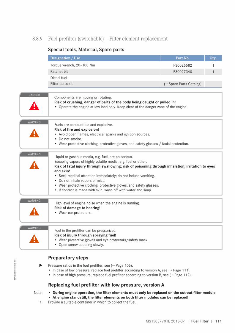
8.8.9 Fuel prefilter (switchable) – Filter element replacement
Special tools, Material, Spare partsDesignation / Use Part No. Qty.
Torque wrench, 20–100 Nm F30026582 1Ratchet bit F30027340 1Diesel fuelFilter parts kit (→ Spare Parts Catalog)
DANGERComponents are moving or rotating.Risk of crushing, danger of parts of the body being caught or pulled in!• Operate the engine at low load only. Keep clear of the danger zone of the engine.
WARNINGFuels are combustible and explosive.Risk of fire and explosion!• Avoid open flames, electrical sparks and ignition sources.• Do not smoke.• Wear protective clothing, protective gloves, and safety glasses / facial protection.
WARNINGLiquid or gaseous media, e.g. fuel, are poisonous.Escaping vapors of highly volatile media, e.g. fuel or ether.Risk of fatal injury through swallowing; risk of poisoning through inhalation; irritation to eyesand skin!• Seek medical attention immediately; do not induce vomiting.• Do not inhale vapors or mist.• Wear protective clothing, protective gloves, and safety glasses.• If contact is made with skin, wash off with water and soap.
WARNINGHigh level of engine noise when the engine is running.Risk of damage to hearing!• Wear ear protectors.
WARNINGFuel in the prefilter can be pressurized.Risk of injury through spraying fuel!• Wear protective gloves and eye protectors/safety mask.• Open screw-coupling slowly.
Preparatory stepsu Pressure ratios in the fuel prefilter, see (→ Page 106).
• In case of low pressure, replace fuel prefilter according to version A, see (→ Page 111).• In case of high pressure, replace fuel prefilter according to version B, see (→ Page 112).
Replacing fuel prefilter with low pressure, version ANote: • During engine operation, the filter elements must only be replaced on the cut-out filter module!
• At engine standstill, the filter elements on both filter modules can be replaced!1. Provide a suitable container in which to collect the fuel.
MS15037/01E 2018-07 | Fuel Filter | 111
TIM
-ID: 0
0000
8005
1 - 0
01

2. During engine operation, turn the switchoverlevel as far as the stop (arrow) to cut out thefilter module to be serviced.
Result: • Filter module (1) is cut in• Filter module (2) is cut out
3. Check fuel level in filter.Result: If the fuel level is stable, the filter can be re-
placed!4. If the fuel level falls, the switchover point is
leaking. Screw on the filter cover again imme-diately and vent the filter (→ Page 114).Check the switchover point, contact Service.
Note: • As soon as the filter housing is opened,absolute cleanness is imperative!
• Carefully extract the filter element straightup avoiding contact with the upper edge ofthe cylinder if at all possible to preventcontamination of the fuel remaining in thefilter housing.
5. Unscrew filter cover (1) and pull it togetherwith filter element (3) out of filter housing (4).
6. Unclip filter element (3) from filter cover (1).7. Install new O-ring (2) on filter cover (1).8. Coat new O-rings on filter cover and filter ele-
ment with fuel.9. Clip new filter element (3) into filter cover (1).
10. Screw filter cover (1) into filter housing.Result: Filter cover (1) must lie flat on the housing
(4).
11. Tighten filter cover (1) with torque wrench to the specified tightening torque.
Name Size Type Lubricant Value/Standard
Filter cover Tightening torque 40 Nm
12. Replace other filter elements in the same way.13. Vent fuel prefilter (→ Page 114).14. Check fuel prefilter for leaks.
Replacing fuel prefilter with high pressure, version BNote: The filter modules must only be replaced with the engine at a standstill!
1. Provide a suitable container in which to collect the fuel.2. Stop engine and disable engine start.3. Close fuel inlet.
112 | Fuel Filter | MS15037/01E 2018-07
TIM
-ID: 0
0000
8005
1 - 0
01

4. Open threaded vent plug and ensure that fueldoes not emerge continuously.
Result: The filter can now be replaced!5. If fuel emerges continuously, check shutoff
valve in fuel supply, notify Service.
Note: • As soon as the filter housing is opened,absolute cleanness is imperative!
• Carefully extract the filter element straightup avoiding contact with the upper edge ofthe cylinder if at all possible to preventcontamination of the fuel remaining in thefilter housing.
6. Unscrew filter cover (1) and pulll it togetherwith filter element (3) from filter housing (4).
7. Unclip filter element (3) from filter cover (1).8. Install new O-ring (2) on filter cover (1).9. Coat new O-rings on filter cover and filter ele-
ment with fuel.10. Clip new filter element (3) into filter cover (1).11. Screw filter cover (1) into filter housing.
Result: Filter cover (1) must lie flat on the housing(4).
12. Tighten filter cover (1) with torque wrench to the specified tightening torque.
Name Size Type Lubricant Value/Standard
Filter cover Tightening torque 40 Nm
13. Replace other filter elements in the same way.14. Open fuel supply.15. Vent fuel prefilter (→ Page 114).16. Check fuel prefilter for leaks.
MS15037/01E 2018-07 | Fuel Filter | 113
TIM
-ID: 0
0000
8005
1 - 0
01

8.8.10 Fuel prefilter – Venting
DANGERComponents are moving or rotating.Risk of crushing, danger of parts of the body being caught or pulled in!• Operate the engine at low load only. Keep clear of the danger zone of the engine.
WARNINGFuels are combustible and explosive.Risk of fire and explosion!• Avoid open flames, electrical sparks and ignition sources.• Do not smoke.• Wear protective clothing, protective gloves, and safety glasses / facial protection.
WARNINGLiquid or gaseous media, e.g. fuel, are poisonous.Escaping vapors of highly volatile media, e.g. fuel or ether.Risk of fatal injury through swallowing; risk of poisoning through inhalation; irritation to eyesand skin!• Seek medical attention immediately; do not induce vomiting.• Do not inhale vapors or mist.• Wear protective clothing, protective gloves, and safety glasses.• If contact is made with skin, wash off with water and soap.
WARNINGExhaust gases are harmful to health and may cause cancer.Risk of poisoning and suffocation!• Keep the engine room well-ventilated at all times.• Repair leaking exhaust pipework immediately.
WARNINGHigh level of engine noise when the engine is running.Risk of damage to hearing!• Wear ear protectors.
WARNINGFuel in the prefilter can be pressurized.Risk of injury through spraying fuel!• Wear protective gloves and eye protectors/safety mask.• Open screw-coupling slowly.
Preparatory steps1. Pressure ratios in the fuel prefilter, see (→ Page 106).
• In case of underpressure, replace fuel prefilter according to version A, see (→ Page 114).• In case of overpressure, replace fuel prefilter according to version B, see (→ Page 115).
2. With the non-switchable fuel prefilter, the engine must be shut down and secured against starting.3. With the switchable fuel prefilter, the cut-out filter module can be vented during engine operation.
Venting fuel prefilter with low pressure, version A1. Open fuel supply as necessary.
114 | Fuel Filter | MS15037/01E 2018-07
TIM
-ID: 0
0000
5827
9 - 0
07

2. Release threaded vent plugs (2, 3) and un-screw at least one rotation.
Note: • Only operate the fuel priming pump man-ually!
• Only hold the pump plunger vertically toavoid damaging the pump!
3. Unlock fuel priming pump, screw out han-dle (1).
Note: Catch escaping fuel with a suitable rag.4. Operate fuel priming pump handle (1) until
bubble-free fuel emerges from the threadedvent plugs (2, 3).
Note: Never actuate the handle with the threadedvent plugs closed!
5. Move handle (1) of fuel priming pump backand screw in.
6. Close threaded vent plugs (2, 3) and tightenby hand.
Venting fuel prefilter with highpressure, version B
1. Open fuel supply as necessary.2. Carefully release threaded vent plugs (1) and
unscrew at least one rotation.3. Leave threaded vent plugs (1) opened until
bubble-free fuel emerges at the vent plugs.4. Close threaded vent plugs (1) and tighten by
hand.
MS15037/01E 2018-07 | Fuel Filter | 115
TIM
-ID: 0
0000
5827
9 - 0
07

8.9 Air Filter
8.9.1 Air filter – Replacement
Special tools, Material, Spare partsDesignation / Use Part No. Qty.
Air filter (→ Spare Parts Catalog)Filter element (→ Spare Parts Catalog)Filter element (→ Spare Parts Catalog)
WARNINGThe engine draws in large volumes of ambient air for combustion. This air intake results in a strong vac-uum.Risk of injury if body parts are drawn in! There is also a danger if opening of the entrance doorcan be prevented!• Only operate the engine with installed air filters.• Never open air-carrying components during operation.• Ensure that the engine room is well-ventilated.
Replacing air filter1. Remove air filter(s) and install new one(s) (→ Page 117).2. Reset signal ring of contamination indicator (→ Page 124).
116 | Air Filter | MS15037/01E 2018-07
TIM
-ID: 0
0000
1338
5 - 0
03
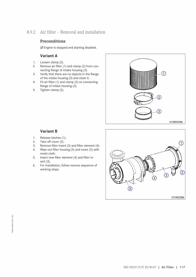
8.9.2 Air filter – Removal and installation
Preconditions☑Engine is stopped and starting disabled.
Variant A1. Loosen clamp (2).2. Remove air filter (1) and clamp (2) from con-
necting flange of intake housing (3).3. Verify that there are no objects in the flange
of the intake housing (3) and clean it.4. Fit air filter (1) and clamp (2) on connecting
flange of intake housing (3).5. Tighten clamp (2).
Variant B1. Release latches (1).2. Take off cover (2).3. Remove filter insert (3) and filter element (4).4. Wipe out filter housing (5) and cover (2) with
moist cloth.5. Insert new filter element (4) and filter in-
sert (3).6. For installation, follow reverse sequence of
working steps.
MS15037/01E 2018-07 | Air Filter | 117
TIM
-ID: 0
0000
1339
5 - 0
02

8.10 Starting Equipment
8.10.1 Electric starter ‒ Overview
1 Starter2 Gasket3 Flange
4 Gasket5 Stud6 Washer
7 Nut
118 | Starting Equipment | MS15037/01E 2018-07
TIM
-ID: 0
0000
2915
2 - 0
03

8.10.2 Starter – Removal
Preconditions☑Engine is stopped and starting disabled.
DANGERElectric voltage supply for operation.Danger of burns and fatal electric shock!• Make certain that the power supply to the product is switched off before starting work. Secure
against unintentional switching on!
WARNINGStarter heats up during the starting procedure.Risk of burning, in particular to the hands!• Avoid skin contact with the starter.• Wear suitable protective equipment, e.g industrial gloves.
WARNINGHeavy part, risk of falling or overturning due to lack of stability.Risk of crushing body or limbs!• Use appropriate lifting gear and appliances.• Wear safety shoes.
Disconnecting and removing starter1. Disconnect starter battery.2. Prior to disconnection, mark all cables.3. Disconnect all cables from starter.4. Protect all cables from damage.5. Remove starter nuts as shown in overview drawing (→ Page 118).6. Remove starter.7. Protect starter from damage.
MS15037/01E 2018-07 | Starting Equipment | 119
TIM
-ID: 0
0000
6104
8 - 0
03

8.10.3 Starter – Installation
Preconditions☑Engine is stopped and starting disabled.
DANGERElectric voltage supply for operation.Danger of burns and fatal electric shock!• Make certain that the power supply to the product is switched off before starting work. Secure
against unintentional switching on!
WARNINGHeavy part, risk of falling or overturning due to lack of stability.Risk of crushing body or limbs!• Use appropriate lifting gear and appliances.• Wear safety shoes.
Installing starter1. Coat starter pinion with lubricating grease.2. Install starter as per overview drawing (→ Page 118).
Connecting starter electrically1. Connect cables in accordance with the marking.
2. Screw on nuts of connections and tighten to specified torque using a torque wrench.a) Terminal 30 (battery connection)
Name Size Type Lubricant Value/Standard
Nut M12 Tightening torque 24.7 to 27.5 Nm
b) Terminal 50 (switching connection)
Name Size Type Lubricant Value/Standard
Nut M6 Tightening torque 5 to 7 Nm
c) Terminal 31 (negative terminal)
Name Size Type Lubricant Value/Standard
Nut M10 Tightening torque 13.5 to 15.8 Nm
3. Connect starter battery.4. Check operation of starter.
120 | Starting Equipment | MS15037/01E 2018-07
TIM
-ID: 0
0000
5468
2 - 0
05

8.10.4 Pneumatic starter – Overview
1 Pressure reducing valve2 Starting valve3 Gasket4 Flange
5 Gasket6 Stud7 Washer8 Hex nut
9 Threaded adapter10 Pneumatic starter
MS15037/01E 2018-07 | Starting Equipment | 121
TIM
-ID: 0
0000
6721
7 - 0
02

8.10.5 Starter – Removal
Preconditions☑Preparatory steps have been completed.
DANGERRotating, moving engine parts.Danger of crushing, danger of body parts being drawn in or caught!• Ensure that the engine can not be started.• After completion of work, make sure that all protective devices are installed.
WARNINGCompressed-air pipes may still be under pressure, although the shut-off valve is closed.Risk of injury!• Before starting work, release pressure from pipework.
WARNINGHeavy part, risk of falling or overturning due to lack of stability.Risk of crushing body or limbs!• Use appropriate lifting gear and appliances.• Wear safety shoes.
Removing starter1. Remove pressure hose.2. Remove starter as per overview drawing (→ Page 121).3. Protect starter from damage.
122 | Starting Equipment | MS15037/01E 2018-07
TIM
-ID: 0
0000
0608
3 - 0
05

8.10.6 Starter ‒ Installation
Special tools, Material, Spare partsDesignation / Use Part No. Qty.
Torque wrench, 8–40 Nm F30043446 1Ring socket, 24 mm F30501562 1Lubricating grease (Molykote Longtherm 2 Plus NLGI 2) X00057299 1Sealing tape 50155 1
WARNINGHeavy part, risk of falling or overturning due to lack of stability.Risk of crushing body or limbs!• Use appropriate lifting gear and appliances.• Wear safety shoes.
Starter ‒ Installation1. Coat starter pinion with lubricating grease.2. Install starter as shown in overview drawing (→ Page 121).
Connecting air starter1. Install pressure hose.2. Fit sealing tape on screw-fitting union. It should cover the entire thread of the union.
3. Tighten threaded adapter to specified torque using a torque wrench.
Name Size Type Lubricant Value/Standard
Union M16x1.5(1/4"NPT)
Tightening torque (Sealing tape) 40 Nm
4. Check if starter works properly.
MS15037/01E 2018-07 | Starting Equipment | 123
TIM
-ID: 0
0000
7995
8 - 0
01

8.11 Air Intake
8.11.1 Service indicator – Signal ring position check
Preconditions☑Engine is stopped and starting disabled.
Checking signal ring position1. When the yellow piston (2) has reached the
red-shaded Service lettering (3), replace airfilter (→ Page 116).
2. After installation of new filter, press resetbutton (1).
Result: Signal ring returns to initial position.
124 | Air Intake | MS15037/01E 2018-07
TIM
-ID: 0
0000
7662
3 - 0
01

8.12 Lube Oil System, Lube Oil Circuit
8.12.1 Engine oil level – Check
Preconditions☑Engine is stopped and starting disabled.
Checking oil level prior to en-gine start
1. Pull out dipstick from guide tube and wipe it.2. Insert dipstick into guide tube up to the stop,
pull it out after approx. 10 seconds andcheck oil level.
3. Oil level must be between "min." (2) and"max." (1) marks.
4. Top up with oil up to the "max" (1) mark(→ Page 126) if required.
5. Insert oil dipstick into guide tube up to thestop.
Checking engine oil level after engine has stopped1. 5 minutes after stopping the engine, pull out oil dipstick from guide tube and wipe it.2. Insert dipstick into guide tube up to the stop, pull it out after approx. 10 seconds and check oil level.3. Oil level must be between “min.” and "max." marks.4. Top up to "max." if required (→ Page 126).5. Insert oil dipstick into guide tube up to the stop.
MS15037/01E 2018-07 | Lube Oil System, Lube Oil Circuit | 125
TIM
-ID: 0
0000
0003
2 - 0
04
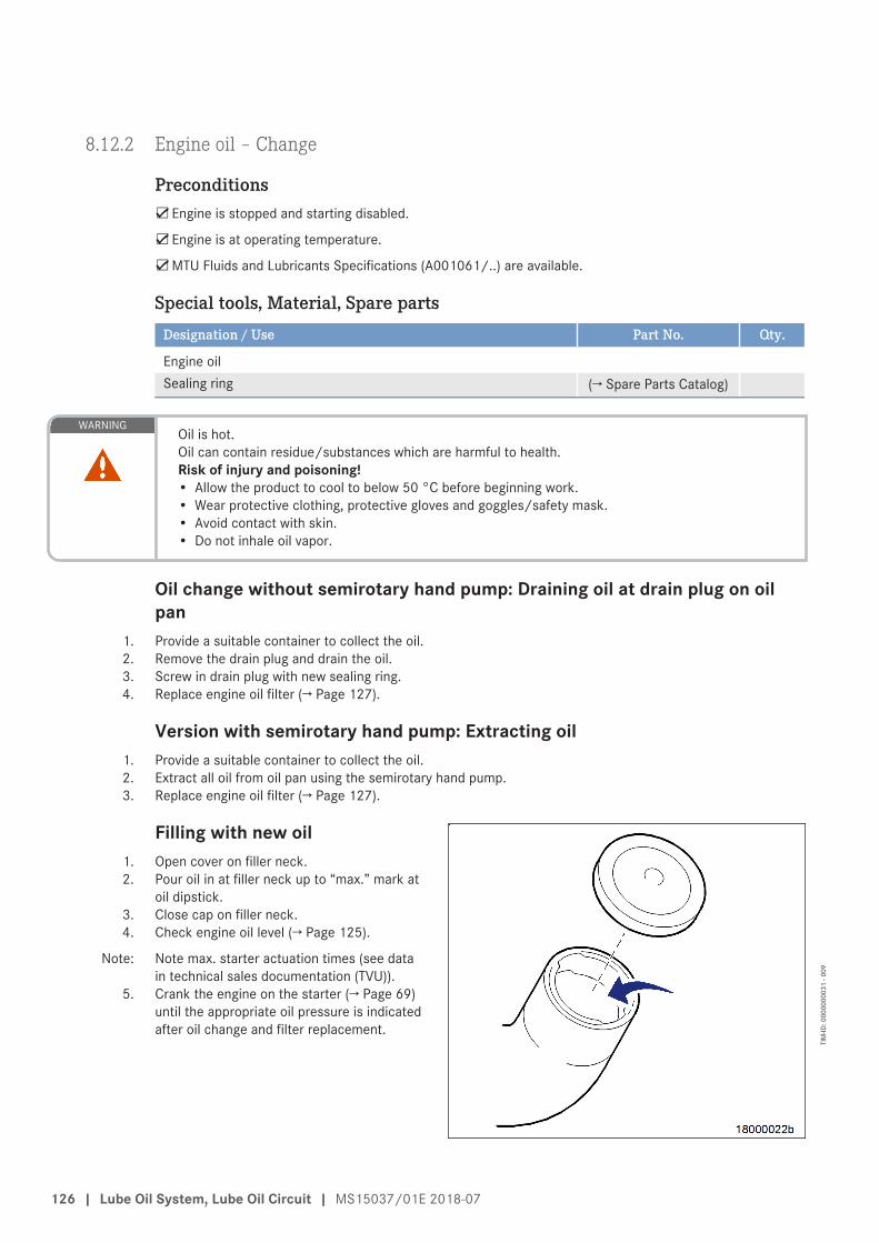
8.12.2 Engine oil – Change
Preconditions☑Engine is stopped and starting disabled.
☑Engine is at operating temperature.
☑MTU Fluids and Lubricants Specifications (A001061/..) are available.
Special tools, Material, Spare partsDesignation / Use Part No. Qty.
Engine oilSealing ring (→ Spare Parts Catalog)
WARNINGOil is hot.Oil can contain residue/substances which are harmful to health.Risk of injury and poisoning!• Allow the product to cool to below 50 °C before beginning work.• Wear protective clothing, protective gloves and goggles/safety mask.• Avoid contact with skin.• Do not inhale oil vapor.
Oil change without semirotary hand pump: Draining oil at drain plug on oilpan
1. Provide a suitable container to collect the oil.2. Remove the drain plug and drain the oil.3. Screw in drain plug with new sealing ring.4. Replace engine oil filter (→ Page 127).
Version with semirotary hand pump: Extracting oil1. Provide a suitable container to collect the oil.2. Extract all oil from oil pan using the semirotary hand pump.3. Replace engine oil filter (→ Page 127).
Filling with new oil1. Open cover on filler neck.2. Pour oil in at filler neck up to “max.” mark at
oil dipstick.3. Close cap on filler neck.4. Check engine oil level (→ Page 125).
Note: Note max. starter actuation times (see datain technical sales documentation (TVU)).
5. Crank the engine on the starter (→ Page 69)until the appropriate oil pressure is indicatedafter oil change and filter replacement.
126 | Lube Oil System, Lube Oil Circuit | MS15037/01E 2018-07
TIM
-ID: 0
0000
0003
1 - 0
09
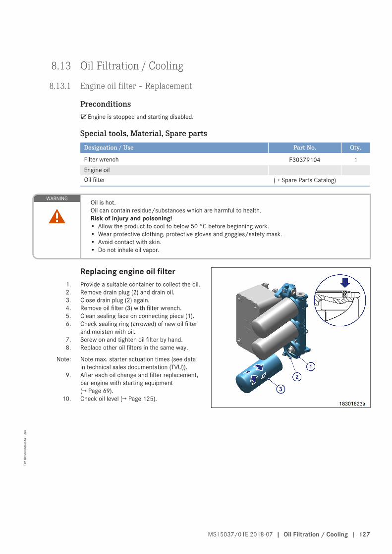
8.13 Oil Filtration / Cooling
8.13.1 Engine oil filter – Replacement
Preconditions☑Engine is stopped and starting disabled.
Special tools, Material, Spare partsDesignation / Use Part No. Qty.
Filter wrench F30379104 1Engine oilOil filter (→ Spare Parts Catalog)
WARNINGOil is hot.Oil can contain residue/substances which are harmful to health.Risk of injury and poisoning!• Allow the product to cool to below 50 °C before beginning work.• Wear protective clothing, protective gloves and goggles/safety mask.• Avoid contact with skin.• Do not inhale oil vapor.
Replacing engine oil filter1. Provide a suitable container to collect the oil.2. Remove drain plug (2) and drain oil.3. Close drain plug (2) again.4. Remove oil filter (3) with filter wrench.5. Clean sealing face on connecting piece (1).6. Check sealing ring (arrowed) of new oil filter
and moisten with oil.7. Screw on and tighten oil filter by hand.8. Replace other oil filters in the same way.
Note: Note max. starter actuation times (see datain technical sales documentation (TVU)).
9. After each oil change and filter replacement,bar engine with starting equipment(→ Page 69).
10. Check oil level (→ Page 125).
MS15037/01E 2018-07 | Oil Filtration / Cooling | 127
TIM
-ID: 0
0000
5345
6 - 0
04

8.14 Coolant Circuit, General, High-Temperature Circuit
8.14.1 Drain and vent points
Plan view
1 Coolant vent, HT circuit 2 Coolant vent, HT circuit 3 Coolant vent, HT circuit
128 | Coolant Circuit, General, High-Temperature Circuit | MS15037/01E 2018-07
TIM
-ID: 0
0000
8014
3 - 0
01

Left side
1 Coolant drain plug, crank-case driving end
2 Coolant drain plug, crank-case free end
MS15037/01E 2018-07 | Coolant Circuit, General, High-Temperature Circuit | 129
TIM
-ID: 0
0000
8014
3 - 0
01

Right side
1 Engine coolant drain plug 2 Coolant drain plug, crank-case free end
3 Coolant drain plug, crank-case driving end
130 | Coolant Circuit, General, High-Temperature Circuit | MS15037/01E 2018-07
TIM
-ID: 0
0000
8014
3 - 0
01
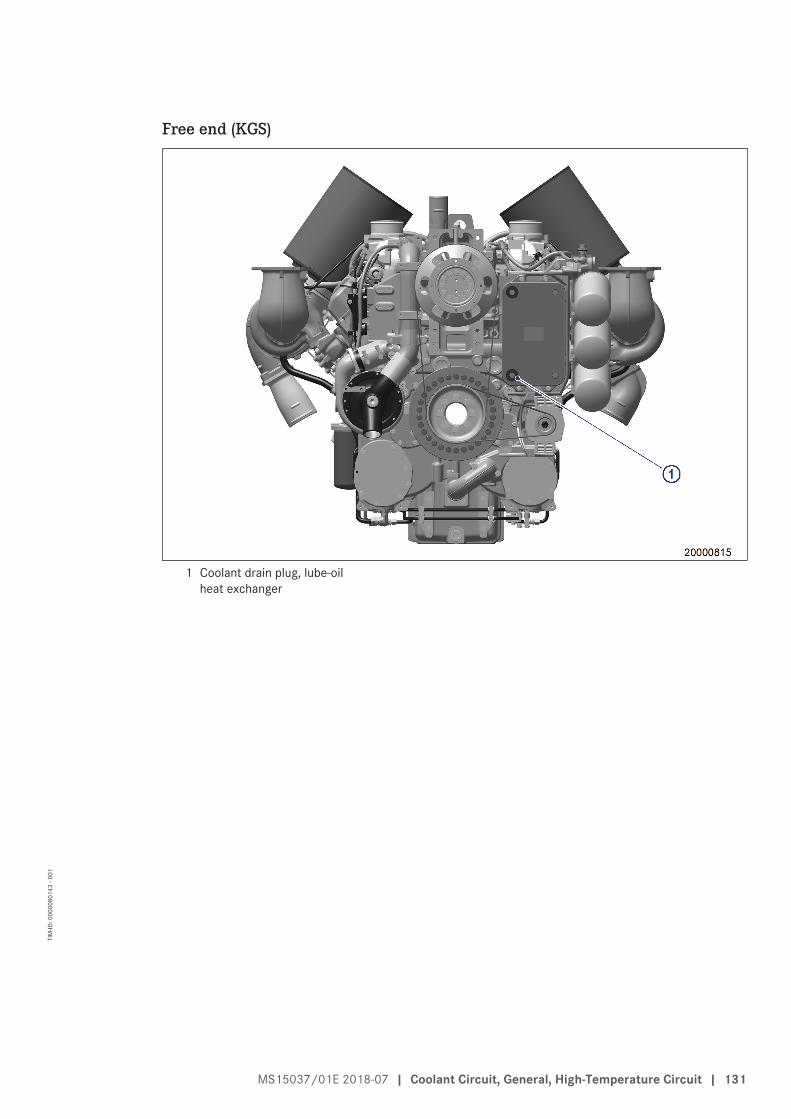
Free end (KGS)
1 Coolant drain plug, lube-oilheat exchanger
MS15037/01E 2018-07 | Coolant Circuit, General, High-Temperature Circuit | 131
TIM
-ID: 0
0000
8014
3 - 0
01
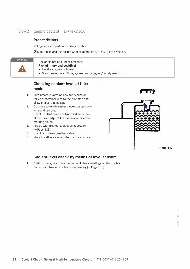
8.14.2 Engine coolant – Level check
Preconditions☑Engine is stopped and starting disabled.
☑MTU Fluids and Lubricants Specifications (A001061/..) are available.
WARNINGCoolant is hot and under pressure.Risk of injury and scalding!• Let the engine cool down.• Wear protective clothing, gloves, and goggles / safety mask.
Checking coolant level at fillerneck:
1. Turn breather valve on coolant expansiontank counterclockwise to the first stop andallow pressure to escape.
2. Continue to turn breather valve counterclock-wise and remove.
3. Check coolant level (coolant must be visibleat the lower edge of the cast-in eye or at themarking plate).
4. Top up with treated coolant as necessary(→ Page 135).
5. Check and clean breather valve.6. Place breather valve on filler neck and close.
Coolant-level check by means of level sensor:1. Switch on engine control system and check readings on the display.2. Top up with treated coolant as necessary (→ Page 135).
132 | Coolant Circuit, General, High-Temperature Circuit | MS15037/01E 2018-07
TIM
-ID: 0
0000
0003
7 - 0
04

8.14.3 Engine coolant – Change
Special tools, Material, Spare partsDesignation / Use Part No. Qty.
Coolant
Engine coolant change1. Drain engine coolant (→ Page 134).2. Fill with engine coolant (→ Page 135).
MS15037/01E 2018-07 | Coolant Circuit, General, High-Temperature Circuit | 133
TIM
-ID: 0
0000
0003
6 - 0
31

8.14.4 Engine coolant – Draining
Preconditions☑Engine is stopped and starting disabled.
WARNINGCoolant is hot and under pressure.Risk of injury and scalding!• Let the engine cool down.• Wear protective clothing, gloves, and goggles / safety mask.
Preparatory steps1. Provide a suitable container to catch coolant.2. Switch off preheater.
Engine coolant – Draining1. Turn valve cover on coolant expansion tank
counterclockwise to first stop and releasepressure.
2. Continue to turn valve cover counterclock-wise and take off.
3. Draw off precipitated corrosion inhibitor oilfrom the coolant expansion tank through fillerneck.
4. Open drain valves or drain plugs and drainengine coolant at the following drain points:• At the preheater;• At HT coolant pump (1);• At the crankcase (1) and (2), right side.
5. Draining of residual coolant:• At the crankcase (1) and (2), left side;• At the oil heat exchanger.
6. Close all open drain points.7. Position valve cover on filler neck and close.
134 | Coolant Circuit, General, High-Temperature Circuit | MS15037/01E 2018-07
TIM
-ID: 0
0000
5148
6 - 0
03

8.14.5 Engine coolant – Filling
Preconditions☑Engine is stopped and starting disabled.
☑MTU Fluids and Lubricants Specifications (A001061/..) are available.
Special tools, Material, Spare partsDesignation / Use Part No. Qty.
Coolant
WARNINGCoolant is hot and under pressure.Risk of injury and scalding!• Let the engine cool down.• Wear protective clothing, gloves, and goggles / safety mask.
WARNINGHigh level of engine noise when the engine is running.Risk of damage to hearing!• Wear ear protectors.
NOTICECold coolant in hot engine can cause thermal stress.Possible formation of cracks in the engine!• Fill / top up coolant only into cold engine.
Preparatory steps1. Turn breather valve (1) on coolant expansion
tank counterclockwise to the first stop andallow pressure to escape.
2. Continue to turn breather valve (1) counter-clockwise and remove.
Engine coolant – Filling1. Fill coolant through filler neck on expansion tank or through filling line until coolant level reaches lower edge
of cast-in eye or marking plate.2. Check proper condition of breather valve (1), clean sealing faces if required.3. Fit breather valve (1) and close it.
MS15037/01E 2018-07 | Coolant Circuit, General, High-Temperature Circuit | 135
TIM
-ID: 0
0000
0003
4 - 0
08

Final steps1. Start the engine and operate it at idle speed for some minutes.2. Check coolant level (→ Page 132), top up with coolant if required.
136 | Coolant Circuit, General, High-Temperature Circuit | MS15037/01E 2018-07
TIM
-ID: 0
0000
0003
4 - 0
08

8.14.6 Engine coolant pump – Relief bore check
DANGERComponents are moving or rotating.Risk of crushing, danger of parts of the body being caught or pulled in!• Operate the engine at low load only. Keep clear of the danger zone of the engine.
WARNINGHigh level of engine noise when the engine is running.Risk of damage to hearing!• Wear ear protectors.
Engine coolant pump – Reliefbore check
u Check relief bore for oil and coolant dis-charge.• Permissible coolant discharge: Up to
2.5 ml/10 hoursResult: Contact Service if discharge exceeds the
specified limits.
MS15037/01E 2018-07 | Coolant Circuit, General, High-Temperature Circuit | 137
TIM
-ID: 0
0000
5701
5 - 0
03
8.15 Coolant System
8.15.1 Coolant cooler – External contamination and leak-tightness check
Preconditions☑Engine-generator set is stopped and starting disabled.
☑All coolant cooler power sources are disconnected.
WARNINGCoolant is hot and under pressure.Risk of injury and scalding!• Let the engine cool down.• Wear protective clothing, gloves, and goggles / safety mask.
Checking coolant cooler for contamination and leak-tightnessItem Findings ActionCheck coolant cooler for coolantloss.
Leakage Contact Service.
Check front of coolant cooler (fanside) for contamination.
Dust and foreign bodies Clean contaminated and cloggedsurface (→ Page 139).Contact Service if extensive clean-ing work is necessary.
Check all other components exter-nally for contamination.
Dust and foreign bodies Vacuum clean or brush off.
138 | Coolant System | MS15037/01E 2018-07
TIM
-ID: 0
0000
4910
1 - 0
03

8.15.2 Coolant cooler – Cleaning
Preconditions☑Engine-generator set is stopped and starting disabled.
WARNINGCompressed air gun ejects a jet of pressurized air.Risk of injury to eyes and damage to hearing, risk of rupturing internal organs!• Never direct air jet at people.• Always wear safety goggles/face mask and ear defenders.
WARNINGChemical substances in cleaners.Risk of irritation and chemical burns!• Always obey manufacturer's instructions for use.
NOTICECleaning agents should not be left to take effect for too long.Damage to components is possible!• Observe manufacturer's instructions.
NOTICEInappropriate cleaning tool.Risk of damage to component!• Observe manufacturer's instructions.• Use appropriate cleaning tool.
Cleaning with industrial vacuum cleanerNote: An industrial vacuum cleaner may only be used on the fan side of the coolant cooler.
1. Remove the fan guard completely to expose the fan side.2. Vacuum dirt away.3. Re-install fan guard completely.
MS15037/01E 2018-07 | Coolant System | 139
TIM
-ID: 0
0000
4910
2 - 0
03

Cleaning with compressed-airgun and industrial high-pressurecleaner
1. Blow out the louvers from the back (1) of thecooler directing a jet of compressed-airagainst the direction of cooling air flow.
Note: Only direct the jet at right angles (90°) to thecooler surface (1) with the nozzle (2) of thecompressed air gun. Failure to do so maydamage the louvers and lead to a loss ofcooling capacity.
2. Remove and dispose of the dirt before put-ting the engine-generator set into operation.
3. If the coolers are still badly contaminatedwith dirt, clean the surfaces from the back ofthe cooler (1) with an industrial high-pres-sure cleaner. Use a hot-water cleaner by wayof preference. Add a suitable degreasingagent to the water (in accordance with therecommendations of the high-pressure clean-er manufacturer. The degreasing agent mustnot contain ammonia and be approved forcoolers containing aluminum alloy compo-nents, otherwise, it would have a corrosiveeffect on the cooler.
Note: Observe the following instructions. Failure todo so may damage the louvers and lead to aloss of cooling capacity.• Direct the water jet against the direction
of cooling air flow.• Direct the water jet (2) at right an-
gles (90°) to the cooler surface (1).• The distance (d) between cooler surface
and nozzle shall not be closer than450 mm (18 inches) at pressures up to206 bar (3,000 psi). The distance must beincreased accordingly at pressures rangingabove this limit value.
• The diameter (Ø) of the water jet shall notbe less than 200 mm (8 inches).
4. Thoroughly dry the cooler and the surround-ing areas before putting the engine-generatorset into operation.
140 | Coolant System | MS15037/01E 2018-07
TIM
-ID: 0
0000
4910
2 - 0
03

8.16 Battery-Charging Generator
8.16.1 Drive belt – Condition check
Preconditions☑Engine is stopped and starting disabled.
☑Guard is removed.
Drive belt – Condition check
Item Findings ActionDrive belt A Singular cracks NoneDrive belt B Cracks on entire circumference Replace (→ Page 145)Drive belt C ChunkingDrive belt Belt is oily, shows signs of over-
heating
MS15037/01E 2018-07 | Battery-Charging Generator | 141
TIM
-ID: 0
0000
8122
8 - 0
01
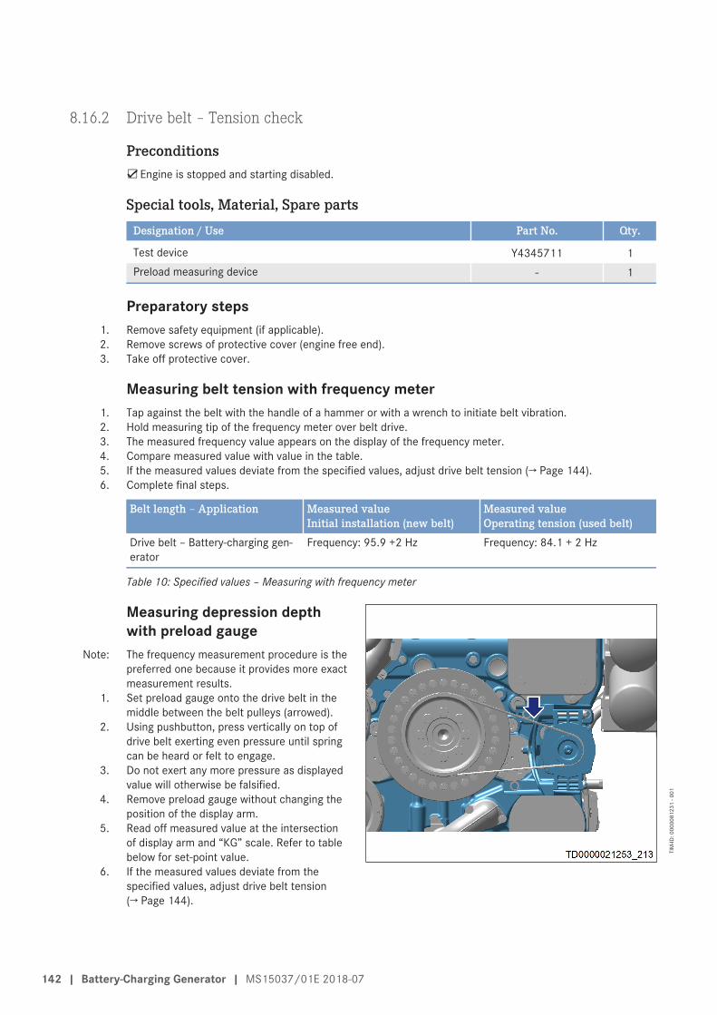
8.16.2 Drive belt – Tension check
Preconditions☑Engine is stopped and starting disabled.
Special tools, Material, Spare partsDesignation / Use Part No. Qty.
Test device Y4345711 1Preload measuring device - 1
Preparatory steps1. Remove safety equipment (if applicable).2. Remove screws of protective cover (engine free end).3. Take off protective cover.
Measuring belt tension with frequency meter1. Tap against the belt with the handle of a hammer or with a wrench to initiate belt vibration.2. Hold measuring tip of the frequency meter over belt drive.3. The measured frequency value appears on the display of the frequency meter.4. Compare measured value with value in the table.5. If the measured values deviate from the specified values, adjust drive belt tension (→ Page 144).6. Complete final steps.
Belt length ‒ Application Measured valueInitial installation (new belt)
Measured valueOperating tension (used belt)
Drive belt – Battery-charging gen-erator
Frequency: 95.9 +2 Hz Frequency: 84.1 + 2 Hz
Table 10: Specified values ‒ Measuring with frequency meter
Measuring depression depthwith preload gauge
Note: The frequency measurement procedure is thepreferred one because it provides more exactmeasurement results.
1. Set preload gauge onto the drive belt in themiddle between the belt pulleys (arrowed).
2. Using pushbutton, press vertically on top ofdrive belt exerting even pressure until springcan be heard or felt to engage.
3. Do not exert any more pressure as displayedvalue will otherwise be falsified.
4. Remove preload gauge without changing theposition of the display arm.
5. Read off measured value at the intersectionof display arm and “KG” scale. Refer to tablebelow for set-point value.
6. If the measured values deviate from thespecified values, adjust drive belt tension(→ Page 144).
142 | Battery-Charging Generator | MS15037/01E 2018-07
TIM
-ID: 0
0000
8123
1 - 0
01

Belt length ‒ Application Measured valueInitial installation (new belt,runtime 0.5-2 h)
Measured value(used belt, runtime 500 h)
Drive belt – Battery-charging gen-erator
Depression depth: 7.8 mmTest force: 60 N
Depression depth: 8.9 mmTest force: 60 N
Table 11: Specified values ‒ Measuring with preload gauge
7. Complete final steps.
Final steps1. Install protective cover.2. Install screws of protective cover.3. Install safety equipment (if applicable).4. Check function of safety equipment (if applicable).
MS15037/01E 2018-07 | Battery-Charging Generator | 143
TIM
-ID: 0
0000
8123
1 - 0
01

8.16.3 Drive belt ‒ Tension adjustment
Preconditions☑Engine is stopped and starting disabled.
Special tools, Material, Spare partsDesignation / Use Part No. Qty.
Torque wrench, 8–40 Nm F30453004/21 1Ratchet bit F30027340 1Engine oil
Preparatory steps1. Remove safety equipment (if applicable).2. Remove screws of protective cover (engine free end).3. Take off protective cover.
Drive belt ‒ Tension adjustment1. Loosen screws (1) and trickle oil into the gap
between gearcase (3) and battery-charginggenerator mount (2).
2. Undo locknut (5).
3. Tighten screws (1) to specified tightening torque.
Name Size Type Lubricant Value/Standard
Screw M10 Preload torque 10 Nm
4. Tighten clamping bolt (4) to specified tightening torque and tension belt to desired value (→ Page 142).
Name Size Type Lubricant Value/Standard
Clamping bolt - Preload torque approx. 8 Nm
5. Tighten screws (1).6. Secure clamping bolt (4) with locknut (5).
Final steps1. Install protective cover.2. Install screws of protective cover.3. Install safety equipment (if applicable).4. Check function of safety equipment (if applicable).
144 | Battery-Charging Generator | MS15037/01E 2018-07
TIM
-ID: 0
0000
8123
3 - 0
01

8.16.4 Drive belt – Replacement
Preconditions☑Engine is stopped and starting disabled.
Special tools, Material, Spare partsDesignation / Use Part No. Qty.
Torque wrench, 8–40 Nm F30453004/21 1Ratchet bit F30027340 1Engine oilDrive belt (→ Spare Parts Catalog) 1
Preparatory steps1. Remove safety equipment (if fitted).2. Remove screws of protective cover (engine free end).3. Take off protective cover.
Replacing drive belt1. For initial installation: Moisten running surfa-
ces of the battery-charging generatormount (2) with oil.
2. Loosen screws (1) and trickle oil into the gapbetween gearcase (3) and battery-charginggenerator mount (2).
3. Undo locknut (5).4. Undo clamping bolt (4).5. Remove drive belt.6. Check cleanness of belt pulleys.7. Fit new drive belt on belt pulleys without ten-
sion.8. Adjust belt tension (→ Page 144).
Final steps1. Install protective cover.2. Install screws of protective cover.3. Install safety equipment (if fitted).4. Check function of safety equipment (if fitted).
MS15037/01E 2018-07 | Battery-Charging Generator | 145
TIM
-ID: 0
0000
5457
2 - 0
05

8.17 Preheater
8.17.1 Preheater – Overhaul
Preconditions☑Engine is stopped and starting disabled.
☑All preheater power sources are disconnected.
Replacing solenoid switchPreheater 3 kW, 230 V, 50 Hz (→ Page 159)
Preheater 3 kW, 240 V, 60 Hz (→ Page 161)
Preheater 6 kW, 400 V, 50/60 Hz (→ Page 157)
Preheater 6 kW, 280 V, 50/60 Hz
Cleaning heating element and replacing gasketPreheater 3 kW, 230 V, 50 Hz (→ Page 151)
Preheater 3 kW, 240 V, 60 Hz (→ Page 154)
Preheater 6 kW, 400 V, 50/60 Hz (→ Page 148)
Preheater 6 kW, 280 V, 50/60 Hz
Replacing thermostatPreheater 3 kW, 230 V, 50 Hz (→ Page 166)
Preheater 3 kW, 240 V, 60 Hz (→ Page 169)
Preheater 6 kW, 400 V, 50/60 Hz (→ Page 163)
Preheater 6 kW, 280 V, 50/60 Hz
146 | Preheater | MS15037/01E 2018-07
TIM
-ID: 0
0000
8298
1 - 0
01
8.17.2 Preheater – Function and leak check
Preconditions☑Preheater is switched on.
WARNINGCoolant is hot and highly pressurized.Risk of injury! Risk of scalding!• Allow engine to cool down.• Wear protective clothing, protective gloves, and safety glasses / facial protection.
Function checkNote: The preheater operates properly if the measured value of the coolant temperature is within the control range
of the thermostat.1. Check coolant preheating temperature.2. Contact Service if the temperatures are out of normal range.
Leak check1. Check unit for leaks at coolant inlet and coolant outlet.2. Tighten leaking connections.
MS15037/01E 2018-07 | Preheater | 147
TIM
-ID: 0
0000
8204
3 - 0
02

8.17.3 Preheater – Heating element and housing check
Preconditions☑Engine is stopped and starting disabled.
Special tools, Material, Spare partsDesignation / Use Part No. Qty.
Screw locking compound (Loctite 586) 40033 1O-ring (→ Spare Parts Catalog) 1
DANGERElectric voltage supply for operation.Danger of burns and fatal electric shock!• Make certain that the power supply to the product is switched off before starting work. Secure
against unintentional switching on!
WARNINGHot components/surfaces.Risk of burns!• Allow the engine to cool down to below 50 °C before beginning work.• Wear suitable protective equipment/thermal gloves.• Avoid unprotected contact with hot surfaces.
WARNINGCoolant is hot and under pressure.Risk of injury and scalding!• Let the engine cool down.• Wear protective clothing, gloves, and goggles / safety mask.
WARNINGCoolant contains antifreeze and is toxic.Risk of poisoning and slipping!• Avoid contact with eyes and skin.• Do not inhale vapors or mist, wear breathing protection.• Do not eat, drink, smoke when working with antifreeze.• Wear protective clothing, protective gloves and goggles/safety mask.• Wipe up escaped/spilled coolant immediately.
NOTICECold coolant in hot engine can cause thermal stress.Possible formation of cracks in the engine!• Fill / top up coolant only into cold engine.
Preparatory steps1. Switch off preheater.2. Disconnect all preheater power sources.3. Allow heating elements to cool down.
Removing coolant lines1. Close shutoff valves in coolant return line and coolant supply line.
148 | Preheater | MS15037/01E 2018-07
TIM
-ID: 0
0000
8191
3 - 0
04
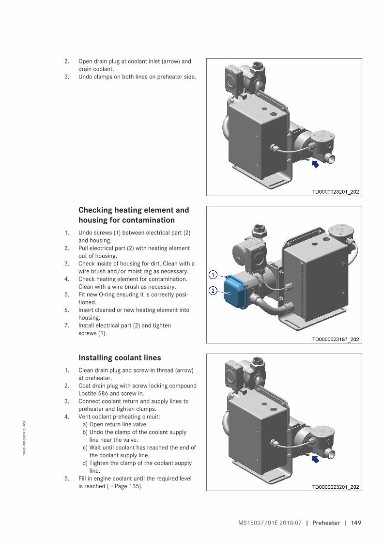
2. Open drain plug at coolant inlet (arrow) anddrain coolant.
3. Undo clamps on both lines on preheater side.
Checking heating element andhousing for contamination
1. Undo screws (1) between electrical part (2)and housing.
2. Pull electrical part (2) with heating elementout of housing.
3. Check inside of housing for dirt. Clean with awire brush and/or moist rag as necessary.
4. Check heating element for contamination.Clean with a wire brush as necessary.
5. Fit new O-ring ensuring it is correctly posi-tioned.
6. Insert cleaned or new heating element intohousing.
7. Install electrical part (2) and tightenscrews (1).
Installing coolant lines1. Clean drain plug and screw-in thread (arrow)
at preheater.2. Coat drain plug with screw locking compound
Loctite 586 and screw in.3. Connect coolant return and supply lines to
preheater and tighten clamps.4. Vent coolant preheating circuit:
a) Open return line valve.b) Undo the clamp of the coolant supply
line near the valve.c) Wait until coolant has reached the end of
the coolant supply line.d) Tighten the clamp of the coolant supply
line.5. Fill in engine coolant until the required level
is reached (→ Page 135).
MS15037/01E 2018-07 | Preheater | 149
TIM
-ID: 0
0000
8191
3 - 0
04
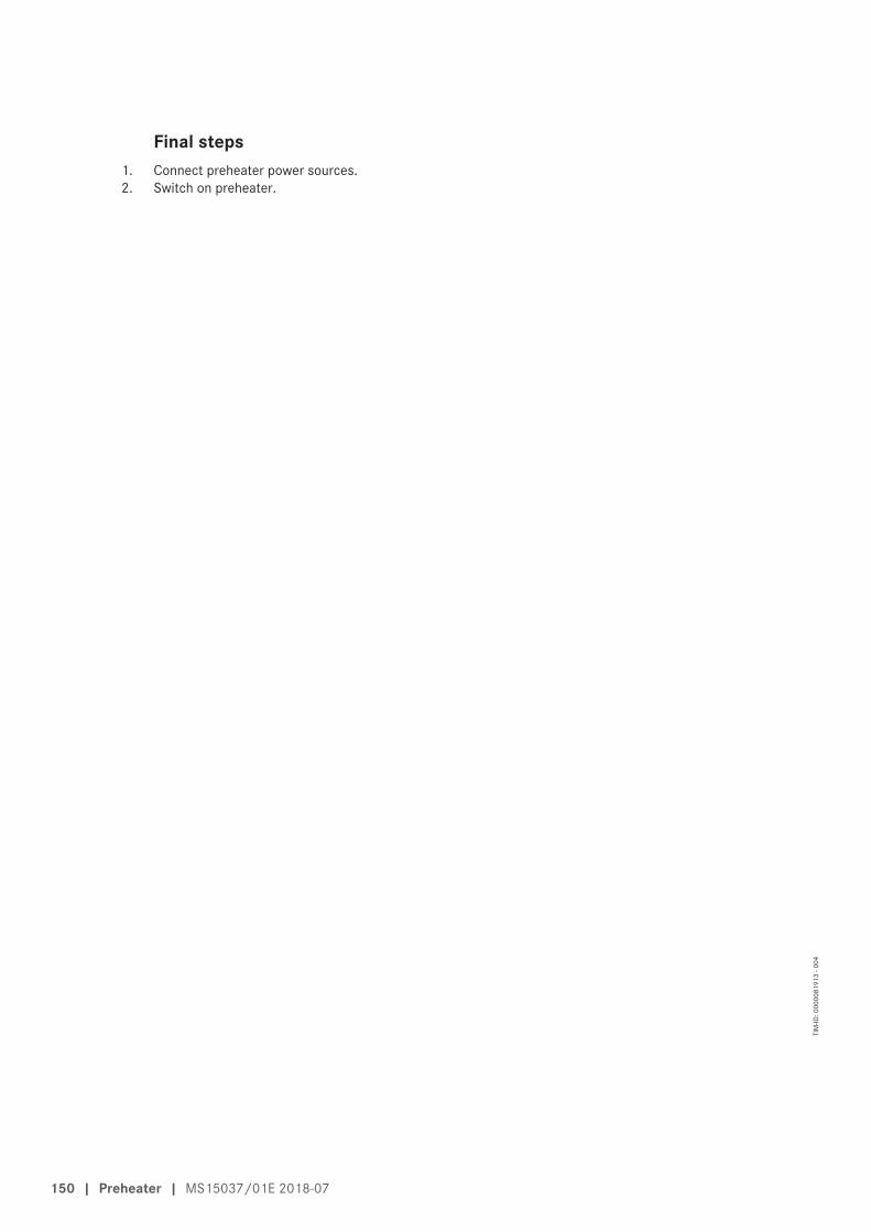
Final steps1. Connect preheater power sources.2. Switch on preheater.
150 | Preheater | MS15037/01E 2018-07
TIM
-ID: 0
0000
8191
3 - 0
04

8.17.4 Preheater – Heating element and housing check
Preconditions☑Engine is stopped and starting disabled.
Special tools, Material, Spare partsDesignation / Use Part No. Qty.
Screw locking compound (Loctite 586) 40033 1O-ring (→ Spare Parts Catalog) 1
DANGERElectric voltage supply for operation.Danger of burns and fatal electric shock!• Make certain that the power supply to the product is switched off before starting work. Secure
against unintentional switching on!
WARNINGHot components/surfaces.Risk of burns!• Allow the engine to cool down to below 50 °C before beginning work.• Wear suitable protective equipment/thermal gloves.• Avoid unprotected contact with hot surfaces.
WARNINGCoolant is hot and under pressure.Risk of injury and scalding!• Let the engine cool down.• Wear protective clothing, gloves, and goggles / safety mask.
WARNINGCoolant contains antifreeze and is toxic.Risk of poisoning and slipping!• Avoid contact with eyes and skin.• Do not inhale vapors or mist, wear breathing protection.• Do not eat, drink, smoke when working with antifreeze.• Wear protective clothing, protective gloves and goggles/safety mask.• Wipe up escaped/spilled coolant immediately.
NOTICECold coolant in hot engine can cause thermal stress.Possible formation of cracks in the engine!• Fill / top up coolant only into cold engine.
Preparatory steps1. Switch off preheater.2. Disconnect all preheater power sources.3. Allow heating elements to cool down.
Removing coolant lines1. Close shutoff valves in coolant return line and coolant supply line.
MS15037/01E 2018-07 | Preheater | 151
TIM
-ID: 0
0000
8297
9 - 0
01
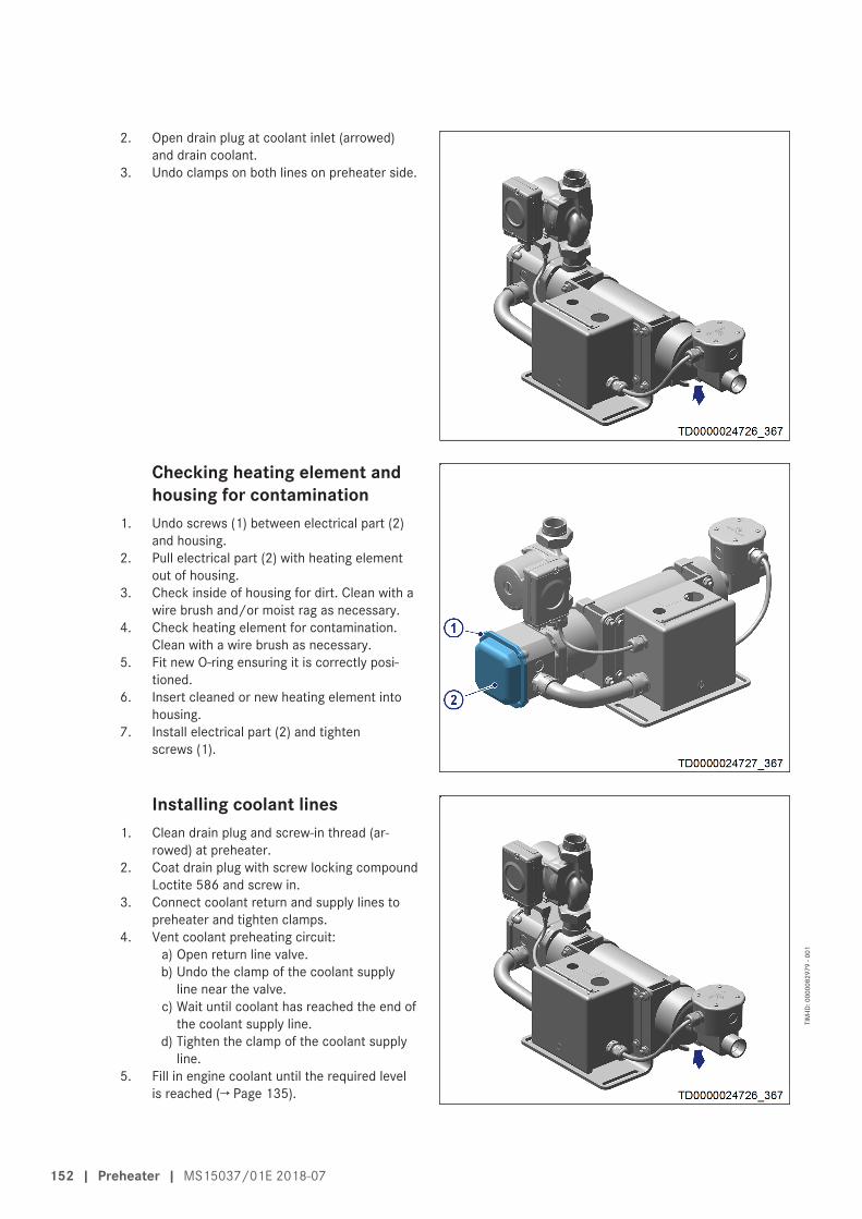
2. Open drain plug at coolant inlet (arrowed)and drain coolant.
3. Undo clamps on both lines on preheater side.
Checking heating element andhousing for contamination
1. Undo screws (1) between electrical part (2)and housing.
2. Pull electrical part (2) with heating elementout of housing.
3. Check inside of housing for dirt. Clean with awire brush and/or moist rag as necessary.
4. Check heating element for contamination.Clean with a wire brush as necessary.
5. Fit new O-ring ensuring it is correctly posi-tioned.
6. Insert cleaned or new heating element intohousing.
7. Install electrical part (2) and tightenscrews (1).
Installing coolant lines1. Clean drain plug and screw-in thread (ar-
rowed) at preheater.2. Coat drain plug with screw locking compound
Loctite 586 and screw in.3. Connect coolant return and supply lines to
preheater and tighten clamps.4. Vent coolant preheating circuit:
a) Open return line valve.b) Undo the clamp of the coolant supply
line near the valve.c) Wait until coolant has reached the end of
the coolant supply line.d) Tighten the clamp of the coolant supply
line.5. Fill in engine coolant until the required level
is reached (→ Page 135).
152 | Preheater | MS15037/01E 2018-07
TIM
-ID: 0
0000
8297
9 - 0
01

Final steps1. Connect preheater power sources.2. Switch on preheater.
MS15037/01E 2018-07 | Preheater | 153
TIM
-ID: 0
0000
8297
9 - 0
01

8.17.5 Preheater – Heating element and housing check
Preconditions☑Engine is stopped and starting disabled.
Special tools, Material, Spare partsDesignation / Use Part No. Qty.
Screw locking compound (Loctite 586) 40033 1O-ring (→ Spare Parts Catalog) 1
DANGERElectric voltage supply for operation.Danger of burns and fatal electric shock!• Make certain that the power supply to the product is switched off before starting work. Secure
against unintentional switching on!
WARNINGHot components/surfaces.Risk of burns!• Allow the engine to cool down to below 50 °C before beginning work.• Wear suitable protective equipment/thermal gloves.• Avoid unprotected contact with hot surfaces.
WARNINGCoolant is hot and under pressure.Risk of injury and scalding!• Let the engine cool down.• Wear protective clothing, gloves, and goggles / safety mask.
WARNINGCoolant contains antifreeze and is toxic.Risk of poisoning and slipping!• Avoid contact with eyes and skin.• Do not inhale vapors or mist, wear breathing protection.• Do not eat, drink, smoke when working with antifreeze.• Wear protective clothing, protective gloves and goggles/safety mask.• Wipe up escaped/spilled coolant immediately.
NOTICECold coolant in hot engine can cause thermal stress.Possible formation of cracks in the engine!• Fill / top up coolant only into cold engine.
Preparatory steps1. Switch off preheater.2. Disconnect all preheater power sources.3. Allow heating elements to cool down.
Removing coolant lines1. Close shutoff valves in coolant return line and coolant supply line.
154 | Preheater | MS15037/01E 2018-07
TIM
-ID: 0
0000
8298
0 - 0
01

2. Open drain plug at coolant inlet (arrowed)and drain coolant.
3. Undo clamps on both lines on preheater side.
Checking heating element andhousing for contamination
1. Undo screws (1) between electrical part (2)and housing.
2. Pull electrical part (2) with heating elementout of housing.
3. Check inside of housing for dirt. Clean with awire brush and/or moist rag as necessary.
4. Check heating element for contamination.Clean with a wire brush as necessary.
5. Fit new O-ring ensuring it is correctly posi-tioned.
6. Insert cleaned or new heating element intohousing.
7. Install electrical part (2) and tightenscrews (1).
Installing coolant lines1. Clean drain plug and screw-in thread (ar-
rowed) at preheater.2. Coat drain plug with screw locking compound
Loctite 586 and screw in.3. Connect coolant return and supply lines to
preheater and tighten clamps.4. Vent coolant preheating circuit:
a) Open return line valve.b) Undo the clamp of the coolant supply
line near the valve.c) Wait until coolant has reached the end of
the coolant supply line.d) Tighten the clamp of the coolant supply
line.5. Fill in engine coolant until the required level
is reached (→ Page 135).
MS15037/01E 2018-07 | Preheater | 155
TIM
-ID: 0
0000
8298
0 - 0
01

Final steps1. Connect preheater power sources.2. Switch on preheater.
156 | Preheater | MS15037/01E 2018-07
TIM
-ID: 0
0000
8298
0 - 0
01

8.17.6 Preheater – Solenoid switch replacement
Preconditions☑Engine is stopped and starting disabled.
Special tools, Material, Spare partsDesignation / Use Part No. Qty.
Solenoid switch (→ Spare Parts Catalog) 1
DANGERElectric voltage supply for operation.Danger of burns and fatal electric shock!• Make certain that the power supply to the product is switched off before starting work. Secure
against unintentional switching on!
WARNINGCoolant is hot and under pressure.Risk of injury and scalding!• Let the engine cool down.• Wear protective clothing, gloves, and goggles / safety mask.
WARNINGHot components/surfaces.Risk of burns!• Allow the engine to cool down to below 50 °C before beginning work.• Wear suitable protective equipment/thermal gloves.• Avoid unprotected contact with hot surfaces.
Preparatory steps1. Switch off preheater.2. Disconnect all preheater power sources.3. Allow heating elements to cool down.4. Close shutoff valves in the supply and return line to/from preheater.
Replacing solenoid switch1. Undo screws on control box (1) and open
control box.
MS15037/01E 2018-07 | Preheater | 157
TIM
-ID: 0
0000
8191
2 - 0
02

2. Mark all cables (4) prior to disconnection.3. Disconnect all cables (4) from solenoid
switch (1).
Note: The solenoid switch is secured to the rail (2)by a spring clip (3).
4. Pull out the spring clip with a screwdriver andslide the solenoid switch off the rail.
5. Fit a new solenoid switch on the rail and fullyengage the spring clip.
6. Connect up all wires as marked previously.7. Close the control box and tighten the screws.
Final steps1. Open shutoff valves in the supply and return line to/from preheater.2. Disconnect preheater power sources.3. Switch on preheater.
158 | Preheater | MS15037/01E 2018-07
TIM
-ID: 0
0000
8191
2 - 0
02

8.17.7 Preheater – Solenoid switch replacement
Preconditions☑Engine is stopped and starting disabled.
Special tools, Material, Spare partsDesignation / Use Part No. Qty.
Solenoid switch (→ Spare Parts Catalog) 1
DANGERElectric voltage supply for operation.Danger of burns and fatal electric shock!• Make certain that the power supply to the product is switched off before starting work. Secure
against unintentional switching on!
WARNINGCoolant is hot and under pressure.Risk of injury and scalding!• Let the engine cool down.• Wear protective clothing, gloves, and goggles / safety mask.
WARNINGHot components/surfaces.Risk of burns!• Allow the engine to cool down to below 50 °C before beginning work.• Wear suitable protective equipment/thermal gloves.• Avoid unprotected contact with hot surfaces.
Preparatory steps1. Switch off preheater.2. Disconnect all preheater power sources.3. Allow heating elements to cool down.4. Close shutoff valves in the supply and return line to/from preheater.
Replacing solenoid switch1. Undo screws on control box (1) and open
control box.
MS15037/01E 2018-07 | Preheater | 159
TIM
-ID: 0
0000
8298
2 - 0
01

2. Mark all cables (1) prior to disconnection.3. Disconnect all cables (1) from solenoid
switch (2).4. Undo screws (3) on solenoid switch (2) and
remove solenoid switch (2).5. Install new solenoid switch (2) and tighten
screws (3).6. Connect up all wires as marked previously.7. Close the control box and tighten the screws.
Final steps1. Open shutoff valves in the supply and return line to/from preheater.2. Disconnect preheater power sources.3. Switch on preheater.
160 | Preheater | MS15037/01E 2018-07
TIM
-ID: 0
0000
8298
2 - 0
01

8.17.8 Preheater – Solenoid switch replacement
Preconditions☑Engine is stopped and starting disabled.
Special tools, Material, Spare partsDesignation / Use Part No. Qty.
Solenoid switch (→ Spare Parts Catalog) 1
DANGERElectric voltage supply for operation.Danger of burns and fatal electric shock!• Make certain that the power supply to the product is switched off before starting work. Secure
against unintentional switching on!
WARNINGCoolant is hot and under pressure.Risk of injury and scalding!• Let the engine cool down.• Wear protective clothing, gloves, and goggles / safety mask.
WARNINGHot components/surfaces.Risk of burns!• Allow the engine to cool down to below 50 °C before beginning work.• Wear suitable protective equipment/thermal gloves.• Avoid unprotected contact with hot surfaces.
Preparatory steps1. Switch off preheater.2. Disconnect all preheater power sources.3. Allow heating elements to cool down.4. Close shutoff valves in the supply and return line to/from preheater.
Replacing solenoid switch1. Undo screws on control box (1) and open
control box.
MS15037/01E 2018-07 | Preheater | 161
TIM
-ID: 0
0000
8298
3 - 0
01
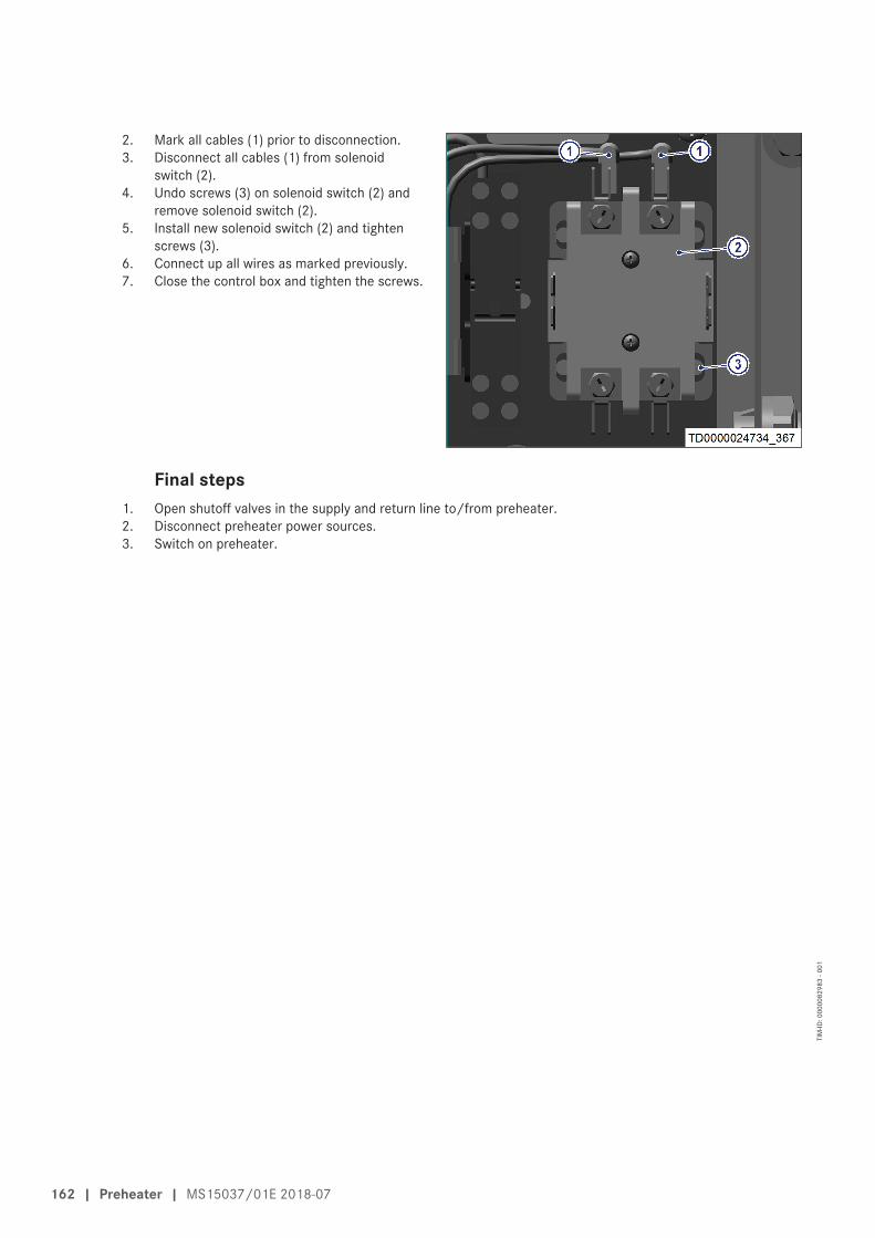
2. Mark all cables (1) prior to disconnection.3. Disconnect all cables (1) from solenoid
switch (2).4. Undo screws (3) on solenoid switch (2) and
remove solenoid switch (2).5. Install new solenoid switch (2) and tighten
screws (3).6. Connect up all wires as marked previously.7. Close the control box and tighten the screws.
Final steps1. Open shutoff valves in the supply and return line to/from preheater.2. Disconnect preheater power sources.3. Switch on preheater.
162 | Preheater | MS15037/01E 2018-07
TIM
-ID: 0
0000
8298
3 - 0
01

8.17.9 Preheater thermostats – Replacement
Preconditions☑Engine is stopped and starting disabled.
Special tools, Material, Spare partsDesignation / Use Part No. Qty.
Thermostat (→ Spare Parts Catalog)
DANGERElectric voltage supply for operation.Danger of burns and fatal electric shock!• Make certain that the power supply to the product is switched off before starting work. Secure
against unintentional switching on!
WARNINGHot components/surfaces.Risk of burns!• Allow the engine to cool down to below 50 °C before beginning work.• Wear suitable protective equipment/thermal gloves.• Avoid unprotected contact with hot surfaces.
WARNINGCoolant is hot and under pressure.Risk of injury and scalding!• Let the engine cool down.• Wear protective clothing, gloves, and goggles / safety mask.
Preparatory steps1. Switch off preheater.2. Disconnect all preheater power sources.3. Allow heating elements to cool down.
Replacing safety thermostat1. Undo screws (1) on cover of electrical
part (2) and remove cover.
MS15037/01E 2018-07 | Preheater | 163
TIM
-ID: 0
0000
8176
2 - 0
02

2. Mark cables prior to disconnection.3. Disconnect terminals from blade terminals of
measuring unit (2).4. Undo thermostat clip (1) and remove safety
thermostat.5. Insert new safety thermostat in recess.6. Secure thermostat clip.7. Connect cable.8. Fit cover and tighten screws.
Replacing control thermostat1. Undo screws (1) on housing cover (2) of con-
trol thermostat and remove cover.
2. Mark cables prior to disconnection.3. Disconnect wires.4. Remove screws (2) and control thermo-
stat (1).5. Install new control thermostat (1) with
screws (2).6. Connect cable.7. Fit housing cover and tighten screws.
164 | Preheater | MS15037/01E 2018-07
TIM
-ID: 0
0000
8176
2 - 0
02
Final steps1. Connect preheater to power supply.2. Switch on preheater.
MS15037/01E 2018-07 | Preheater | 165
TIM
-ID: 0
0000
8176
2 - 0
02

8.17.10 Preheater thermostats – Replacement
Preconditions☑Engine is stopped and starting disabled.
Special tools, Material, Spare partsDesignation / Use Part No. Qty.
Thermostat (→ Spare Parts Catalog)
DANGERElectric voltage supply for operation.Danger of burns and fatal electric shock!• Make certain that the power supply to the product is switched off before starting work. Secure
against unintentional switching on!
WARNINGHot components/surfaces.Risk of burns!• Allow the engine to cool down to below 50 °C before beginning work.• Wear suitable protective equipment/thermal gloves.• Avoid unprotected contact with hot surfaces.
WARNINGCoolant is hot and under pressure.Risk of injury and scalding!• Let the engine cool down.• Wear protective clothing, gloves, and goggles / safety mask.
Preparatory steps1. Switch off preheater.2. Disconnect all preheater power sources.3. Allow heating elements to cool down.
Replacing safety thermostat1. Undo screws (1) on cover of electrical
part (2) and remove cover.
166 | Preheater | MS15037/01E 2018-07
TIM
-ID: 0
0000
8298
4 - 0
01

2. Mark cables prior to disconnection.3. Disconnect terminals from blade terminals of
measuring unit (2).4. Undo thermostat clip (1) and remove safety
thermostat.5. Insert new safety thermostat in recess.6. Secure thermostat clip.7. Connect cable.8. Fit cover and tighten screws.
Replacing control thermostat1. Undo screws (1) on housing cover (2) of con-
trol thermostat and remove cover.
2. Mark cables prior to disconnection.3. Disconnect wires.4. Remove screws (2) and control thermo-
stat (1).5. Install new control thermostat (1) with
screws (2).6. Connect cable.7. Fit housing cover and tighten screws.
MS15037/01E 2018-07 | Preheater | 167
TIM
-ID: 0
0000
8298
4 - 0
01

Final steps1. Connect preheater to power supply.2. Switch on preheater.
168 | Preheater | MS15037/01E 2018-07
TIM
-ID: 0
0000
8298
4 - 0
01

8.17.11 Preheater thermostats – Replacement
Preconditions☑Engine is stopped and starting disabled.
Special tools, Material, Spare partsDesignation / Use Part No. Qty.
Thermostat (→ Spare Parts Catalog)
DANGERElectric voltage supply for operation.Danger of burns and fatal electric shock!• Make certain that the power supply to the product is switched off before starting work. Secure
against unintentional switching on!
WARNINGHot components/surfaces.Risk of burns!• Allow the engine to cool down to below 50 °C before beginning work.• Wear suitable protective equipment/thermal gloves.• Avoid unprotected contact with hot surfaces.
WARNINGCoolant is hot and under pressure.Risk of injury and scalding!• Let the engine cool down.• Wear protective clothing, gloves, and goggles / safety mask.
Preparatory steps1. Switch off preheater.2. Disconnect all preheater power sources.3. Allow heating elements to cool down.
Replacing safety thermostat1. Undo screws (1) on cover of electrical
part (2) and remove cover.
MS15037/01E 2018-07 | Preheater | 169
TIM
-ID: 0
0000
8298
5 - 0
01
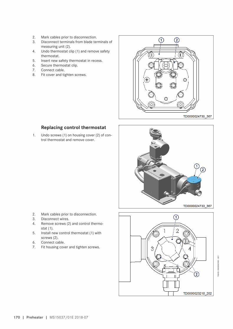
2. Mark cables prior to disconnection.3. Disconnect terminals from blade terminals of
measuring unit (2).4. Undo thermostat clip (1) and remove safety
thermostat.5. Insert new safety thermostat in recess.6. Secure thermostat clip.7. Connect cable.8. Fit cover and tighten screws.
Replacing control thermostat1. Undo screws (1) on housing cover (2) of con-
trol thermostat and remove cover.
2. Mark cables prior to disconnection.3. Disconnect wires.4. Remove screws (2) and control thermo-
stat (1).5. Install new control thermostat (1) with
screws (2).6. Connect cable.7. Fit housing cover and tighten screws.
170 | Preheater | MS15037/01E 2018-07
TIM
-ID: 0
0000
8298
5 - 0
01

Final steps1. Connect preheater to power supply.2. Switch on preheater.
MS15037/01E 2018-07 | Preheater | 171
TIM
-ID: 0
0000
8298
5 - 0
01

8.18 Engine Mounting / Support
8.18.1 Engine mounting – Checking securing screws for firm seating
Preconditions☑Engine is stopped and starting disabled.
Engine mounting, checking securing screws for firm seating1. Check securing screws for firm seating.2. Tighten loose threaded connections.
172 | Engine Mounting / Support | MS15037/01E 2018-07
TIM
-ID: 0
0000
0754
8 - 0
09

8.18.2 Engine mounting – Checking condition of resilient mounts
Preconditions☑Engine is stopped and starting disabled.
Engine mounting – Checking the condition of resilient mounts1. Wipe rubber surface with dry cloth, do not use organic detergents.2. Visually inspect resilient mounts for cracking and deformation.3. Check rubber surfaces for swelling.4. Have cracked or swollen mounts replaced, contact Service.
MS15037/01E 2018-07 | Engine Mounting / Support | 173
TIM
-ID: 0
0000
3893
8 - 0
01

8.19 Generator
8.19.1 Generator mounting – Checking condition of resilient mounts
Preconditions☑Engine is stopped and starting disabled.
Generator mounting – Checking condition of resilient mounts1. Wipe rubber surface with dry cloth, do not use organic detergents.2. Visually inspect resilient mounts for cracks and deformation.3. Check rubber surfaces for swelling.4. Have cracked or swollen mounts replaced, contact Service.
174 | Generator | MS15037/01E 2018-07
TIM
-ID: 0
0000
7944
7 - 0
02

8.19.2 Generator mounting – Checking firm seating of securing screws
Preconditions☑Engine is stopped and starting disabled.
Generator mounting – Checking firm seating of securing screws1. Check securing screws for firm seating.2. Tighten loose screw connections.
MS15037/01E 2018-07 | Generator | 175
TIM
-ID: 0
0000
7944
8 - 0
01

8.20 Engine Governor
8.20.1 Engine Control Unit – Overview
1 Connector X22 Connector X1 (customer
connection)
3 Connector X34 Washer
5 Screw6 Damping element
176 | Engine Governor | MS15037/01E 2018-07
TIM
-ID: 0
0000
5349
1 - 0
02

8.20.2 Engine Control Unit – Removal and installation
Preconditions☑Engine is stopped and starting disabled.
Special tools, Material, Spare partsDesignation / Use Part No. Qty.
Engine Control Unit (→ Spare Parts Catalog) 1Rubber mount (→ Spare Parts Catalog)
NOTICEWrong engine governor installed.Engine damage!• When reassembling an engine, make sure that the governor with the data record for the given engine
is installed.
Removing Engine Control Unitfrom engine
1. Note or mark assignment of cables and con-nectors.
2. Undo latches on connectors (1), (2) (custom-er connection) and (3).
3. Disconnect all connectors.4. Remove all screws (5) with washers (4).5. Take off Engine Control Unit.
Installing Engine Control Unit on engine1. Install in reverse order. Ensure correct assignment of connectors and sockets.2. Check damping element (6) prior to installation.
Result: Replace damping element (6) if porous or faulty.
MS15037/01E 2018-07 | Engine Governor | 177
TIM
-ID: 0
0000
5349
2 - 0
03

8.20.3 Engine governor plug connections – Check
Preconditions☑Engine stopped and starting disabled.
☑Electronic engine management system is de-energized.
NOTICEInsertion of unsuitable test probe, e.g. test prod.The contacts in the plug connection can be bent!• Carry out check of plug connection only with test connectors.
Checking plug connections at engine governor1. Check all plug connections for secure seating.2. Lock loose connectors.3. Check dust cap on ECU and EXU connectors for damage and correct seating.
178 | Engine Governor | MS15037/01E 2018-07
TIM
-ID: 0
0000
0004
8 - 0
09

8.21 Wiring (General) for Engine/Gearbox/Unit
8.21.1 Engine cabling – Check
Preconditions☑Engine is stopped and starting disabled.
Special tools, Material, Spare partsDesignation / Use Part No. Qty.
Solvent (isopropyl alcohol) X00058037 1
Engine cabling – Check1. Check securing screws of cable clamps on engine and tighten loose screw connections.2. Ensure that cables are securely seated in clamps and cannot move freely.3. Check if all cable clips are closed and intact.4. Replace faulty cable clips.5. Check cable clamps for secure fit, tighten loose clamps.6. Replace faulty cable clamps.7. Visually inspect the following electrical components for damage:
• Connector housings• Contacts• Plug connectors• Cables and terminals• Plug-in contacts
Result: If cable conductors are damaged, contact Service.
Note: Close connectors that are not plugged in with the protective cap supplied.8. Use isopropyl alcohol to clean dirty connector housings, plug connectors and contacts.9. Ensure that all connecting plugs of the sensors are correctly engaged.
MS15037/01E 2018-07 | Wiring (General) for Engine/Gearbox/Unit | 179
TIM
-ID: 0
0000
0002
9 - 0
25
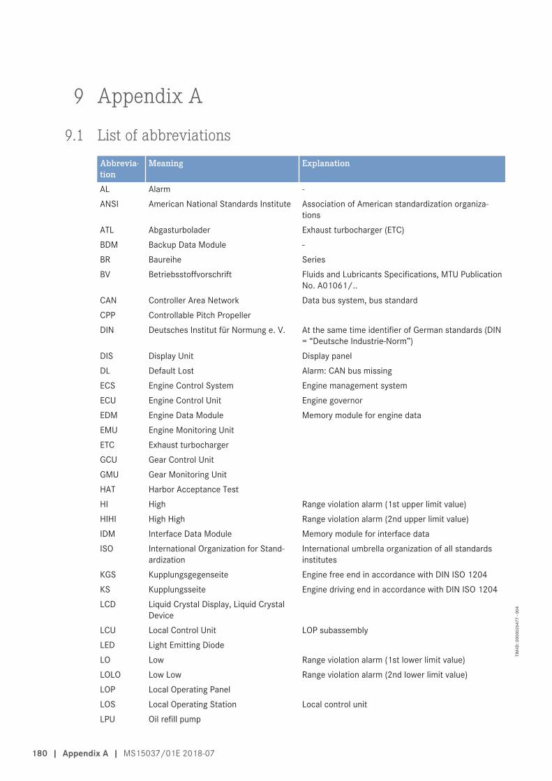
9 Appendix A
9.1 List of abbreviationsAbbrevia-tion
Meaning Explanation
AL Alarm -ANSI American National Standards Institute Association of American standardization organiza-
tionsATL Abgasturbolader Exhaust turbocharger (ETC)BDM Backup Data Module -BR Baureihe SeriesBV Betriebsstoffvorschrift Fluids and Lubricants Specifications, MTU Publication
No. A01061/..CAN Controller Area Network Data bus system, bus standardCPP Controllable Pitch PropellerDIN Deutsches Institut für Normung e. V. At the same time identifier of German standards (DIN
= “Deutsche Industrie-Norm”)DIS Display Unit Display panelDL Default Lost Alarm: CAN bus missingECS Engine Control System Engine management systemECU Engine Control Unit Engine governorEDM Engine Data Module Memory module for engine dataEMU Engine Monitoring UnitETC Exhaust turbochargerGCU Gear Control UnitGMU Gear Monitoring UnitHAT Harbor Acceptance TestHI High Range violation alarm (1st upper limit value)HIHI High High Range violation alarm (2nd upper limit value)IDM Interface Data Module Memory module for interface dataISO International Organization for Stand-
ardizationInternational umbrella organization of all standardsinstitutes
KGS Kupplungsgegenseite Engine free end in accordance with DIN ISO 1204KS Kupplungsseite Engine driving end in accordance with DIN ISO 1204LCD Liquid Crystal Display, Liquid Crystal
DeviceLCU Local Control Unit LOP subassemblyLED Light Emitting DiodeLO Low Range violation alarm (1st lower limit value)LOLO Low Low Range violation alarm (2nd lower limit value)LOP Local Operating PanelLOS Local Operating Station Local control unitLPU Oil refill pump
180 | Appendix A | MS15037/01E 2018-07
TIM
-ID: 0
0000
2647
7 - 0
04

Abbrevia-tion
Meaning Explanation
MCS Monitoring and Control SystemMG MessageMPU Microprocessor Unit, Microprocessing
UnitOT Oberer Totpunkt Top dead center (TDC)PAN Panel Control panelPCU/PMU Propeller Control Unit Propeller controllerPIM Peripheral Interface ModulePPC Priming Pump ControlRCS Remote Control SystemRL Redundancy Lost Alarm: Redundant CAN bus failureSAT Sea Acceptance TestSD Sensor Defect Alarm: Sensor failureSDAF Shut Down Air Flap(s) Emergency air-shutoff flap(s)SS Safety System Safety system alarmSSK Schnellschlussklappen Emergency air-shutoff flap(s)TD Transmitter Deviation Alarm: Sensor comparison faultUT Unterer Totpunkt Bottom dead center (BDC)
MS15037/01E 2018-07 | Appendix A | 181
TIM
-ID: 0
0000
2647
7 - 0
04

9.2 MTU Contact/Service PartnersThe worldwide network of the sales organization with subsidiaries, sales offices, representatives and custom-er service centers ensure fast and direct support on site and ensure the high availability of our products.
Local SupportExperienced and qualified specialists place their knowledge and expertise at your disposal.
For locally available support, go to the MTU Internet site: http://www.mtu-online.com
24h HotlineWith our 24h hotline and high flexibility, we're your contact around the clock: during each operating phase,preventive maintenance and corrective operations in case of a malfunction, for information on changes inconditions of use and for supplying spare parts.
Your contact person in our Customer Assistance Center:
E-mail: [email protected]
Tel.: +49 7541 9077777
Fax.: +49 7541 9077778
Asia/Pacific: +65 6100 2688
North and Latin America: +1 248 560 8000
Spare Parts ServiceFast, simple and correct identification of spare parts for your drive system or vehicle fleet. The right sparepart at the right time at the right place.
With this aim in mind, we can call on a globally networked spares logistics system, a central warehouse atheadquarters and on-site stores at our subsidiary companies, agencies and service workshops.
Your contact at Headquarters:
E-mail: [email protected]
Tel.: +49 7541 9077777
Fax.: +49 7541 9077778
182 | Appendix A | MS15037/01E 2018-07
TIM
-ID: 0
0000
0087
3 - 0
16
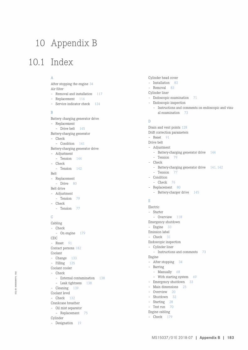
10 Appendix B
10.1 IndexA
After stopping the engine 34Air filter – Removal and installation 117– Replacement 116– Service indicator check 124
B
Battery charging generator drive – Replacement
– Drive belt 145Battery-charging generator – Check
– Condition 141Battery-charging generator drive – Adjustment
– Tension 144– Check
– Tension 142Belt – Replacement
– Drive 80Belt drive – Adjustment
– Tension 79– Check
– Tension 77
C
Cabling – Check
– On engine 179CDC – Reset 91Contact persons 182Coolant – Change 133– Filling 135Coolant cooler – Check
– External contamination 138– Leak tightness 138
– Cleaning 139Coolant level – Check 132Crankcase breather – Oil mist separator
– Replacement 75Cylinder – Designation 19
Cylinder head cover – Installation 83– Removal 83Cylinder liner – Endoscopic examination 71– Endoscopic inspection
– Instructions and comments on endoscopic and visu-al examination 73
D
Drain and vent points 128Drift correction parameters – Reset 91Drive belt – Adjustment
– Battery-charging generator drive 144– Tension 79
– Check – Battery-charging generator drive 141, 142– Tension 77
– Condition – Check 76
– Replacement 80– Battery-charger drive 145
E
Electric – Starter
– Overview 118Emergency shutdown – Engine 33Emission label – Check 31Endoscopic inspection – Cylinder liner
– Instructions and comments 73Engine – After stopping 34– Barring
– Manually 68– With starting system 69
– Emergency shutdown 33– Main dimensions 25– Overview 20– Shutdown 32– Starting 28– Test run 70Engine cabling – Check 179
MS15037/01E 2018-07 | Appendix B | 183
DCL-
ID: 0
0000
4897
6 - 0
02

Engine Control Unit – Fault messages 40– Installation 177– Overview 176– Removal 177Engine coolant – Change 133– Draining 134– Filling 135Engine coolant level – Check 132Engine coolant pump – Relief bore check 137Engine driving end – Definition 19Engine free end – Definition 19Engine governor – Plug connections
– Check 178Engine mounting – Checking condition of resilient mounts 173– Checking securing screws for firm seating 172Engine oil – Change 126Engine oil filter – Replacement 127Engine oil level – Check 125Engine sides – Designation 19
F
Fault messages – Engine Control Unit 40Firing order 24Fuel – Draining 95Fuel cooler – Check
– External contamination 96– Leak-tightness 96
– Cleaning 97Fuel filter – Replacement 99Fuel prefilter – Draining 100
– Non-switchable 101– Switchable 103
– Filter element replacement 108– Non-switchable 109– Switchable 111
– Low pressure indicator check – Switchable 107
– Pressure ratios 106– Venting 114
Fuel system – Installation
– Injector 86– Removal
– Injector 86– Venting 94
G
Generator mounting – Checking condition of resilient mounts 174– Securing screw firm seating check 175
H
Heating element – Check
– Preheater 148, 151, 154Hotline 182Housing – Check
– Preheater 148, 151, 154HP fuel line – Replacement 92
I
IIG – Input 91Injector – Installation 86– Removal 86– Replacement 85Injector coding – Input 91Injector functions 91
L
List of abbreviations 180
M
Main dimensions – Engine 25Maintenance schedule – Maintenance task reference table [QL1] for EPA re-
gions 36MTU contact persons 182
O
Operational monitoring 30Overview – Electric
– Starter 118– Engine 20– Engine Control Unit 176– Starter
– Pneumatic 121
P
Plant – Cleaning 35
184 | Index | MS15037/01E 2018-07
DCL-
ID: 0
0000
4897
6 - 0
02

Preheater – Check
– Heating element 148, 151, 154– Housing 148, 151, 154
– Function check 147– Leak check 147– Overhaul 146– Replacement
– Solenoid switch 157, 159, 161– Thermostat 163, 166, 169
Pressure pipe neck – Replacement 92Product data – 18V2000G76S 21Pump – Engine coolant
– Relief bore check 137
S
Safety regulations – Assembly work 11– Auxiliary materials 15– Environmental protection 15– Fire prevention 15– Fluids and lubricants 15– Important provisions 5, 7– Initial start-up 9– Maintenance work 11– Operation 9– Organizational requirements 8– Personnel requirements 8– Repair work 11Safety requirements – Warning notices, standards 17Service indicator – Check 124Service partners 182Solenoid switch – Replacement
– Preheater 157, 159, 161Spare parts service 182Specifications – Engine
– 18V2000G76S 21Starter – Electric
– Installation 120– Removal 119
– Pneumatic – Installation 123– Overview 121– Removal 122
Startup – after long out-of-service periods (>3 months)
– Preparations 26– after scheduled out-of-service period
– Preparations 27
T
Thermostat – Replacement
– Preheater 163, 166, 169Transport – Description 18Troubleshooting 37
V
Valve clearance – Adjustment 81– Check 81Vent and drain points 128
W
Warning notices, standards 17
MS15037/01E 2018-07 | Index | 185
DCL-
ID: 0
0000
4897
6 - 0
02

10.2 Special ToolsBarring tool
Part No.: F6792910Qty.:Used in:
1 8.1.1 Engine – Barring manually (→ Page 68)
Qty.:Used in:
1 8.2.1 Cylinder liner – Endoscopic examination (→ Page 71)
Qty.:Used in:
1 8.5.1 Valve clearance – Check and adjustment(→ Page 81)
Crossbeam
Part No.: T80091731Qty.:Used in:
1 2.1 Transport (→ Page 18)
Crowfoot wrench, 19 mm
Part No.: F30027424Qty.:Used in:
1 8.6.2 Injector – Removal and installation (→ Page 86)
Qty.:Used in:
1 8.7.1 HP fuel line and pressure pipe neck – Replacement(→ Page 92)
Double-end box wrench
Part No.: F30002800Qty.:Used in:
1 8.5.1 Valve clearance – Check and adjustment(→ Page 81)
186 | Special Tools | MS15037/01E 2018-07
DCL-
ID: 0
0000
4897
6 - 0
02

Double-head box wrench
Part No.: F30011450Qty.:Used in:
1 8.6.2 Injector – Removal and installation (→ Page 86)
Qty.:Used in:
1 8.7.1 HP fuel line and pressure pipe neck – Replacement(→ Page 92)
Endoscope
Part No.: Y20097353Qty.:Used in:
1 8.2.1 Cylinder liner – Endoscopic examination (→ Page 71)
Extraction device
Part No.: F6790636Qty.:Used in:
1 8.6.2 Injector – Removal and installation (→ Page 86)
Filter wrench
Part No.: F30379104Qty.:Used in:
1 8.8.1 Fuel filter – Replacement (→ Page 99)
Qty.:Used in:
1 8.13.1 Engine oil filter – Replacement (→ Page 127)
MS15037/01E 2018-07 | Special Tools | 187
DCL-
ID: 0
0000
4897
6 - 0
02

Fuel suction pipe
Part No.: F30378207Qty.:Used in:
1 8.6.2 Injector – Removal and installation (→ Page 86)
High-pressure cleaner
Part No.:Qty.:Used in:
1 5.10 Plant – Cleaning (→ Page 35)
Measuring device
Part No.: Y4348409Qty.:Used in:
1 8.5.1 Valve clearance – Check and adjustment(→ Page 81)
Offset screwdriver
Part No.: F30453001Qty.:Used in:
1 8.5.1 Valve clearance – Check and adjustment(→ Page 81)
188 | Special Tools | MS15037/01E 2018-07
DCL-
ID: 0
0000
4897
6 - 0
02

Plug-in open-end wrench, 19 mm
Part No.: F30453236Qty.:Used in:
1 8.6.2 Injector – Removal and installation (→ Page 86)
Plug-in open-end wrench, 19 mm
Part No.: F30025897Qty.:Used in:
1 8.7.1 HP fuel line and pressure pipe neck – Replacement(→ Page 92)
Preload gauge, 150–600 N
Part No.: Y20097429Qty.:Used in:
1 8.4.2 Drive belt – Tension check (→ Page 77)
Preload measuring device
Part No.: -Qty.:Used in:
1 8.16.2 Drive belt – Tension check (→ Page 142)
MS15037/01E 2018-07 | Special Tools | 189
DCL-
ID: 0
0000
4897
6 - 0
02

Press-in tool
Part No.: F6790085Qty.:Used in:
1 8.6.2 Injector – Removal and installation (→ Page 86)
Ratchet bit
Part No.: F30027340Qty.:Used in:
1 8.4.3 Drive belt ‒ Tension adjustment (→ Page 79)
Qty.:Used in:
1 8.5.2 Cylinder head cover – Cylinder head cover(→ Page 83)
Qty.:Used in:
1 8.6.2 Injector – Removal and installation (→ Page 86)
Qty.:Used in:
1 8.7.1 HP fuel line and pressure pipe neck – Replacement(→ Page 92)
Qty.:Used in:
1 8.8.8 Fuel prefilter (non-switchable) – Filter element re-placement (→ Page 109)
Qty.:Used in:
1 8.8.9 Fuel prefilter (switchable) – Filter element replace-ment (→ Page 111)
Qty.:Used in:
1 8.16.3 Drive belt ‒ Tension adjustment (→ Page 144)
Qty.:Used in:
1 8.16.4 Drive belt – Replacement (→ Page 145)
Ratchet with extension
Part No.: F30006212Qty.:Used in:
1 8.1.1 Engine – Barring manually (→ Page 68)
Qty.:Used in:
1 8.2.1 Cylinder liner – Endoscopic examination (→ Page 71)
Qty.:Used in:
1 8.5.1 Valve clearance – Check and adjustment(→ Page 81)
190 | Special Tools | MS15037/01E 2018-07
DCL-
ID: 0
0000
4897
6 - 0
02

Ring socket, 22 mm
Part No.: F30038494Qty.:Used in:
1 8.6.2 Injector – Removal and installation (→ Page 86)
Qty.:Used in:
1 8.7.2 Fuel system – Venting (→ Page 94)
Ring socket, 24 mm
Part No.: F30501562Qty.:Used in:
1 8.4.3 Drive belt ‒ Tension adjustment (→ Page 79)
Qty.:Used in:
1 8.4.4 Drive belt – Replacement (→ Page 80)
Qty.:Used in:
1 8.7.1 HP fuel line and pressure pipe neck – Replacement(→ Page 92)
Qty.:Used in:
1 8.10.6 Starter ‒ Installation (→ Page 123)
Socket wrench
Part No.: F30030450Qty.:Used in:
1 8.5.1 Valve clearance – Check and adjustment(→ Page 81)
Socket wrench, 24 mm
Part No.: F30453238Qty.:Used in:
1 8.6.2 Injector – Removal and installation (→ Page 86)
MS15037/01E 2018-07 | Special Tools | 191
DCL-
ID: 0
0000
4897
6 - 0
02

Test device
Part No.: Y4345711Qty.:Used in:
1 8.4.2 Drive belt – Tension check (→ Page 77)
Qty.:Used in:
1 8.16.2 Drive belt – Tension check (→ Page 142)
Torque wrench, 20–100 Nm
Part No.: F30026582Qty.:Used in:
1 8.4.3 Drive belt ‒ Tension adjustment (→ Page 79)
Qty.:Used in:
1 8.5.1 Valve clearance – Check and adjustment(→ Page 81)
Qty.:Used in:
1 8.6.2 Injector – Removal and installation (→ Page 86)
Qty.:Used in:
1 8.7.1 HP fuel line and pressure pipe neck – Replacement(→ Page 92)
Qty.:Used in:
1 8.8.8 Fuel prefilter (non-switchable) – Filter element re-placement (→ Page 109)
Qty.:Used in:
1 8.8.9 Fuel prefilter (switchable) – Filter element replace-ment (→ Page 111)
Torque wrench, 40–200 Nm
Part No.: F30027337Qty.:Used in:
1 8.4.3 Drive belt ‒ Tension adjustment (→ Page 79)
192 | Special Tools | MS15037/01E 2018-07
DCL-
ID: 0
0000
4897
6 - 0
02

Torque wrench, 8–40 Nm
Part No.: F30043446Qty.:Used in:
1 8.5.2 Cylinder head cover – Cylinder head cover(→ Page 83)
Qty.:Used in:
1 8.7.2 Fuel system – Venting (→ Page 94)
Qty.:Used in:
1 8.10.6 Starter ‒ Installation (→ Page 123)
Torque wrench, 8–40 Nm
Part No.: F30453004/21Qty.:Used in:
1 8.16.3 Drive belt ‒ Tension adjustment (→ Page 144)
Qty.:Used in:
1 8.16.4 Drive belt – Replacement (→ Page 145)
Torque wrench, 0.5–5 Nm
Part No.: 0015384230Qty.:Used in:
1 8.5.2 Cylinder head cover – Cylinder head cover(→ Page 83)
Qty.:Used in:
1 8.6.2 Injector – Removal and installation (→ Page 86)
Valve clearance gauge
Part No.: Y4345893Qty.:Used in:
1 8.5.1 Valve clearance – Check and adjustment(→ Page 81)
MS15037/01E 2018-07 | Special Tools | 193
DCL-
ID: 0
0000
4897
6 - 0
02