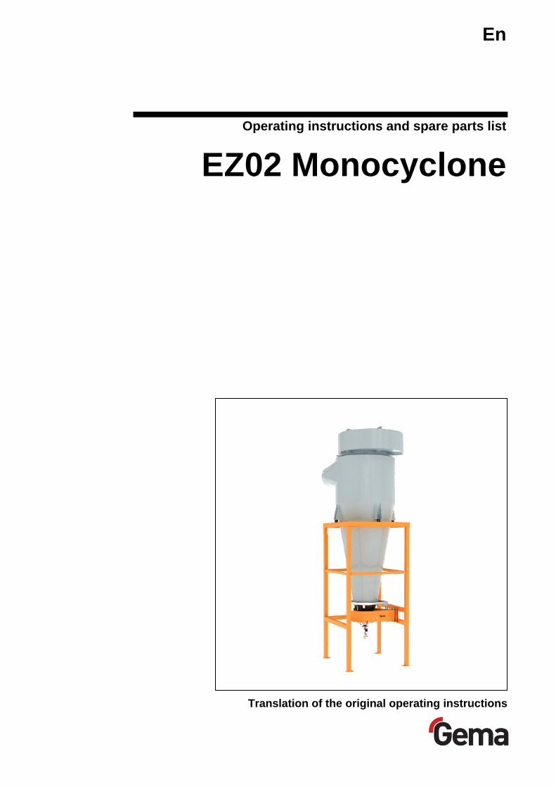
operating instructions and spare parts list ez02 monocyclone
TRANSCRIPT
En
Translation of the original operating instructions
Operating instructions and spare parts list
EZ02 Monocyclone

V 03/13
Documentation EZ02 Monocyclone
© Copyright 2004 Gema Switzerland GmbH.
All rights reserved.
This publication is protected by copyright. Unauthorized copying is pro-hibited by law. No part of this publication may be reproduced, photocop-ied, translated, stored on a retrieval system or transmitted in any form or by any means for any purpose, neither as a whole nor partially, without the express written consent of Gema Switzerland GmbH.
MagicCompact, MagicCylinder, MagicPlus, MagicControl, OptiFlex, Op-tiControl, OptiGun, OptiSelect, OptiStar and SuperCorona are registered trademarks of Gema Switzerland GmbH.
OptiFlow, OptiCenter, OptiMove, OptiSpeeder, OptiFeed, OptiSpray, Op-tiSieve, OptiAir, OptiPlus, OptiMaster, MultiTronic, EquiFlow, Precise Charge Control (PCC), Smart Inline Technology (SIT) and Digital Valve Control (DVC) are trademarks of Gema Switzerland GmbH.
All other product names are trademarks or registered trademarks of their respective holders.
Reference is made in this manual to different trademarks or registered trademarks. Such references do not mean that the manufacturers con-cerned approve of or are bound in any form by this manual. We have en-deavored to retain the preferred spelling of the trademarks, and regis-tered trademarks of the copyright holders.
To the best of our knowledge and belief, the information contained in this publication was correct and valid on the date of publication. Gema Swit-zerland GmbH makes no representations or warranties with respect to the contents or use of this publication, and reserves the right to revise this publication and make changes to its content without prior notice.
For the latest information about Gema products, visit www.gemapowdercoating.com.
For patent information, see www.gemapowdercoating.com/patents or www.gemapowdercoating.us/patents.
Printed in Switzerland
Gema Switzerland GmbH Mövenstrasse 17 9015 St.Gallen Switzerland
Phone: +41-71-313 83 00 Fax.: +41-71-313 83 83
E-Mail: [email protected]

V 03/13
EZ02 Table of contents • 1
Table of contents
General safety regulations 3
Safety symbols (pictograms) ................................................................................... 3 Conformity of use .................................................................................................... 3 Special security measures ...................................................................................... 4
About this manual 5
General information ................................................................................................ 5
Description of function 7
EZ02 Monocyclone ................................................................................................. 7 Delivery unit ............................................................................................................ 8
Security-operation of the delivery unit ....................................................... 8
Technical Data 9
Exhaust air volume / powder application ................................................................ 9 Setting values / parameters .................................................................................... 9 Dimensions ............................................................................................................. 9 Pneumatic diagram ............................................................................................... 10
Assembly notes 11
Setting up and mounting ....................................................................................... 11 Space requirement for delivery unit ...................................................................... 12
Preparation for start-up 13
Important notes ..................................................................................................... 13
Dense phase conveying 15
General information .............................................................................................. 15 Dense phase conveying - PT06 ............................................................... 15 Dense phase conveying - PT07 ............................................................... 15
Description of function .......................................................................................... 16 Vibrator mounting kit (option) ................................................................................ 17
Color change 19
Procedure .............................................................................................................. 19
Maintenance 21
Checkpoints and references ................................................................................. 21 Maintenance - pinch valve .................................................................................... 22
Replacing a pinch valve sleve .................................................................. 22 Maintenance - Sieve mesh tension ....................................................................... 23 Monocyclone sealing ............................................................................................ 24

V 03/13
2 • Table of contents EZ02
Cleaning 25
Cleaning of the connection sleeves ...................................................................... 25 Cleaning of the clean gas connecting sleeve .......................................... 25 Cleaning of the inlet connection sleeve ................................................... 26
Cleaning of the sieve ............................................................................................ 26 Cyclone cleaning granules ................................................................................... 27
Troubleshooting guide 29
Problem fixing ....................................................................................................... 29
Spare parts list 31
Ordering spare parts ............................................................................................. 31 EZ02 Monocyclone - delivery unit, mechanical part ............................................. 32 EZ02 Monocyclone - delivery unit, mechanical part ............................................. 33 EZ02 Monocyclone - delivery unit, pneumatic part .............................................. 34 EZ02 Monocyclone - delivery unit, pneumatic part .............................................. 35 Delivery unit - vibrator, mounting kit ..................................................................... 36 Sieve insert ........................................................................................................... 37 Dense phase conveying - PT06 ........................................................................... 38 Dense phase conveying - PT06 ........................................................................... 39 Dense phase conveying - connections ................................................................. 40
V 03/13
EZ02 General safety regulations • 3
General safety regulations
This chapter sets out the fundamental safety regulations that must be fol-lowed by the user and third parties using the EZ02.
These safety regulations must be read and understood before the EZ02 is used.
Safety symbols (pictograms) The following warnings with their meanings can be found in the Gema operating instructions. The general safety precautions must also be fol-lowed as well as the regulations in the operating instructions.
DANGER! danger due to live electricity or moving parts. Possible consequences: Death or serious injury
WARNING! Improper use of the equipment could damage the machine or cause it to malfunction. Possible consequences: minor injuries or damage to equip-ment
INFORMATION! useful tips and other information
Conformity of use 1. The EZ02 Monocyclone is built to the latest specification and
conforms to the recognized technical safety regulations. It is de-signed for the normal application of powder coating.
2. Any other use is considered as non-conform. The manufacturer is not responsible for damage resulting from improper use of this equipment; the end-user alone is responsible. If the EZ02 Mono-cyclone is to be used for other purposes or other substances outside of our guidelines then Gema Switzerland GmbH should be consulted.
3. Observance of the operating, service and maintenance instruc-tions specified by the manufacturer is also part of conformity of use. The EZ02 Monocyclone should only be used, maintained

V 03/13
4 • General safety regulations EZ02
and started up by trained personnel, who are informed about and are familiar with the possible hazards involved.
4. Start-up (i.e. the execution of a particular operation) is forbidden until it has been established that the EZ02 Monocyclone has been set up and wired according to the guidelines for machinery (2006/42 EG). EN 60204-1 (machine safety) must also be ob-served.
5. Unauthorized modifications to EZ02 Monocyclone exempts the manufacturer from any liability from resulting damage.
6. The relevant accident prevention regulations, as well as other generally recognized safety regulations, occupational health and structural regulations are to be observed.
7. Furthermore the country-specific safety regulations must be ob-served.
Explosion protection
II 3D
Special security measures - The installation work, to be done by the customer, must be
carried out according to local regulations
- Before starting up the plant a check must be made that no foreign objects are in the booth or in the ducting (input and exhaust air)
- It must be observed, that all components are grounded ac-cording to the local regulations, before start-up
NOTE:
For further information, see the more detailed Gema safety regula-tions!

V 03/13
EZ02 About this manual • 5
About this manual
General information These operating manual contains all important information which you re-quire for the working with the EZ02 Monocyclone. It will safely guide you through the start-up process and give you references and tipps for the optimal use of your new powder coating system.
Information about the function mode of the individual system components - reciprocators, booths, powder gun controls, powder guns etc. - you will find in the corresponding enclosed documentations.


V 03/13
EZ02 Description of function • 7
Description of function
EZ02 Monocyclone The EZ02 Monocyclone (as a matter of principle a centrifugal cyclone) separates the coating powder from the booth exhaust air.
The volume of exhaust air, depending on the booth size, the number of guns etc. is created by a fan fitted after the monocyclone and a filter sep-arator. The powder/air mixture arrives at the cyclone through the ducting and the tangetial air input. Now the powder is set in rotation, separated from the air by the centrifugal force and isolated around the cyclone wall. The exhaust air rises up through the central immersion tube in the cy-clone and arrives at the filter separator. Herein, the residual powder is re-tained and the cleaned air is returned into the workshop environment.
EZ02 Monocyclone
Exhaust air spiral
Powder/air entry (from the booth)
Pinch valves (dense phase con-veying)
Proximity switch
Pivoted delivery unit
Exhaust air opening
V 03/13
8 • Description of function EZ02
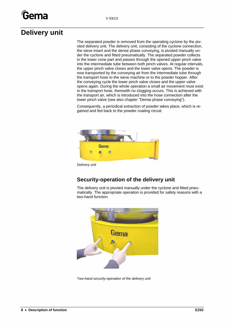
Delivery unit The separated powder is removed from the operating cyclone by the piv-oted delivery unit. The delivery unit, consisting of the cyclone connection, the sieve insert and the dense phase conveying, is pivoted manually un-der the cyclone and fitted pneumatically. The separated powder collects in the lower cone part and passes through the opened upper pinch valve into the intermediate tube between both pinch valves. At regular intervals, the upper pinch valve closes and the lower valve opens. The powder is now transported by the conveying air from the intermediate tube through the transport hose to the sieve machine or to the powder hopper. After the conveying cycle the lower pinch valve closes and the upper valve opens again. During the whole operation a small air movement must exist in the transport hose, therewith no clogging occurs. This is achieved with the transport air, which is introduced into the hose connection after the lower pinch valve (see also chapter "Dense phase conveying").
Consequently, a periodical extraction of powder takes place, which is re-gained and fed back to the powder coating circuit.
Delivery unit
Security-operation of the delivery unit
The delivery unit is pivoted manually under the cyclone and fitted pneu-matically. The appropriate operation is provided for safety reasons with a two-hand function.
Two-hand security-operation of the delivery unit
V 03/13
EZ02 Technical Data • 9
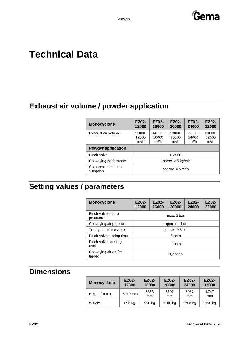
Technical Data
Exhaust air volume / powder application
Monocyclone EZ02-12000
EZ02-16000
EZ02-20000
EZ02-24000
EZ02-32000
Exhaust air volume 11000-12000 m³/h
14000-16000 m³/h
18000-20000 m³/h
22000-24000 m³/h
29000-32000 m³/h
Powder application
Pinch valve NW 65
Conveying performance approx. 2,5 kg/min
Compressed air con-sumption
approx. 4 Nm³/h
Setting values / parameters
Monocyclone EZ02-12000
EZ02-16000
EZ02-20000
EZ02-24000
EZ02-32000
Pinch valve control pressure
max. 3 bar
Conveying air pressure approx. 1 bar
Transport air pressure approx. 0,3 bar
Pinch valve closing time 6 secs
Pinch valve opening time
2 secs
Conveying air on (re-tarded)
0,7 secs
Dimensions Monocyclone
EZ02-12000
EZ02-16000
EZ02-20000
EZ02-24000
EZ02-32000
Height (max.) 5010 mm5383 mm
5707 mm
6057 mm
6747 mm
Weight 850 kg 950 kg 1100 kg 1200 kg 1350 kg
V 03/13
10 • Technical Data EZ02
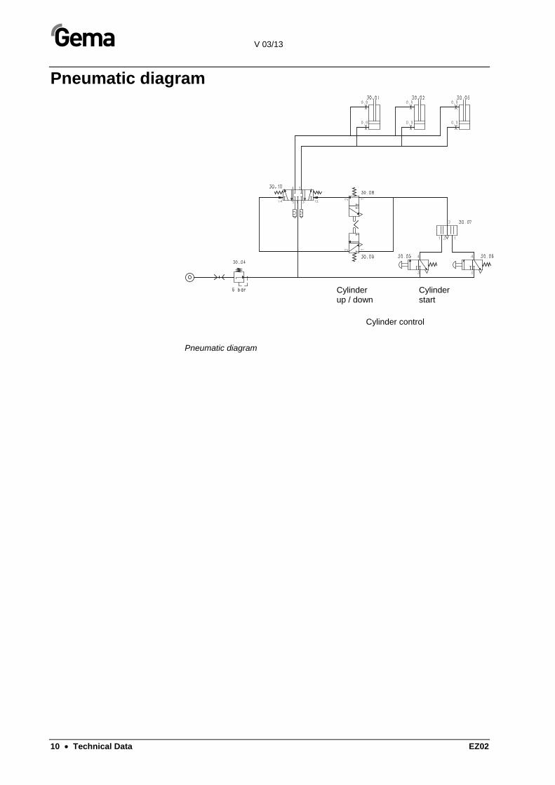
Pneumatic diagram
Pneumatic diagram
Cylinder up / down
Cylinder start
Cylinder control

V 03/13
EZ02 Assembly notes • 11
Assembly notes
Setting up and mounting
WARNING! The assembly procedure for setting up the cyclone must be adapted to the available resources of the customer. Since it concerns heavy and bulky parts, special attention must be given to the security of the assembly personnel. In order to guarantee operating safety, all assembly work must be checked by trained personnel!
Especially the following points must be observed:
- The angle between the air entry and exit can be set by 15° with the existing slots (slots ±7.5°). If the angle must be dis-placed further, the exit spiral must be completely dismantled and can be displaced in 15° steps
- All connecting joints (exit spiral etc.) must be locked hermeti-cally
- It must be observed that all connecting joints in the ducting and inside the cyclone etc. are as smooth as possible, so that no powder can deposit
- In order to ensure the grounding connection from the frame to the cyclone, a vibration damper must be bridged with the supplied grounding cable
- On the separation point of the frame feet and their exten-sions, the feet must also be connected to one another. Three connection profiles are supplied for this. The fourth connec-tion point must be left free for pivoting the delivery unit. The position can be chosen by assembly, according to local con-ditions
- The monocyclone must be firmly anchored to the workshop floor
- The ducting must be assembled as tension-free as possible
- The delivery unit is preassembled ready and for mounting
- For monitoring the correct position of the delivery unit, a proximity switch must be fitted on the cyclone, which gives a signal when the delivery unit is pivoted and lifted to the cy-clone and releases the plant for operation
- The transport hose must be secured with the supplied steel cable to the spring hook of the dense phase conveyor, so

V 03/13
12 • Assembly notes EZ02
that no uncontrolled movement can take place by revertive rinsing and thereby endangering personnel
- The connecting hoses of the delivery unit control and the dense phase conveyor are to be applied in such a way that the delivery unit can be tilt out for cleaning without discon-necting the hose connections
- The delivery unit and the cyclone must be closed tightly dur-ing operation. The seals of the cyclone and of the swivel frame are to be examined regularly
Space requirement for delivery unit Swinging out the delivery unit needs at least 800 mm swiveling area. This place may not be closed or blocked and is used also for operation, clean-ing and maintenance.
Space requirement for delivery unit

V 03/13
EZ02 Preparation for start-up • 13
Preparation for start-up
Important notes
WARNING! The start-up should be done only by trained personnel! Foreign objects in the booth or in the ducting can cause damages to the plant!
Before start-up, the following points are to be checked:
- Are all screw connections on the cyclone and on other plant units firmly tightened?
- Is the ducting and the interior of the cyclone cleaned properly?
- Are all ducting and hose connections connected correct-ly?
- Are there no foreign objects (e.g. screws, small parts etc.) in the booth, the cyclone or the ducting?
- Is the delivery unit completely assembled?
- Are all plant units grounded?
- Is the delivery unit connected correctly? Does the two-hand function (security-operation) of the delivery unit works correctly?
- Is the transport hose connected correctly on the exhaust side?
- Are the settings for the dense phase conveyor correct?
WARNING! The plant may be put into operation after all these points are checked and any faults are corrected!


V 03/13
EZ02 Dense phase conveying • 15
Dense phase conveying
General information The dense phase conveying serves for the transport of the recovered powder to the powder container/hopper in the powder centre. This transport principle permits a very careful and dust-free powder transport because the air requirement and the transport speed are very low.
Dense phase conveying - PT06
This type is the standard dense phase conveying, which is normally de-livered with the cyclone and the delivery unit.
Dense phase conveying - PT07
This type is a curved special version and is only used by lack of space. Further information of this version will be found in the appropriate manu-al.
Dense phase conveying - PT06 Dense phase conveying - PT07

V 03/13
16 • Dense phase conveying EZ02
Description of function 1. The upper pinch valve QV1 opens. The recovered powder falls
through the pinch valve QV1 into the intermediate tube (3), see picture 1
- The lower pinch valve QV2 is thereby closed
- The spiral air (5) is constantly in operation
- The conveying air (2) is switched off
2. The pinch valve QV1 closes
3. The pinch valve QV2 opens
- The pinch valve QV1 is thereby closed
- The spiral air (5) is constantly in operation
- The conveying air (2) is switched on for a short time
Due to the overpressure in the intermediate tube (3), the powder is trans-ported through the pinch valve QV2 into the delivery tube and through the transport hose (7) into the sieve machine by the Powder Centre, see pic-ture 2
4. The pinch valve QV2 closes, see picture 3
- After a short delay the pinch valve QV1 opens again
- The steps 1) to 4) are repeated continuously
QV 1
QV 2
1
1
2 2 2
3
4
555
6
7
QV 1
QV 2
QV 1
QV 2
2 3
Dense phase conveying - description of function
1 Switch valve above
2 Conveying air
3 Intermediate tube
4 Switch valve below
5 Spiral air (constantly on)
6 Delivery nozzle
7 Transport hose

V 03/13
EZ02 Dense phase conveying • 17
The transport efficiency is dependent on the type of powder, the pulse rates and the length of the used transport hose with respective pinch valve and transport hose dimension.
Vibrator mounting kit (option) By using certain powder types, the danger exists that powder deposits can develop in the delivery unit. This is prevented by the optionally avail-able vibrator mounting kit.
The vibrator is installed between the delivery unit and the dense phase conveying (see illustration). It shifts the cone of the delivery unit into easy oscillations and prevents thus accumulations of powder and the emer-gence of deposits and blockages.
NOTE! The vibrator operates only if the upper pinch valve QV1 of the dense phase conveying is opened
Vibrator mounting kit (option)


V 03/13
EZ02 Color change • 19
Color change
Procedure The following points are to be observed at colour changes:
1. In order to save time and powder at a colour change, the clean-ing should be made in the flow direction of the powder. But cleaning the powder guns and the booth should be done first. During this phase, the powder can be transported back into the powder hopper or the powder container with the dense phase conveyor
2. The delivery unit is detached from the cyclone. By the aspirated wrong air at the cyclone lower part, the powder separation now is void and all resulting powder is fed to the After Filter
3. Procedure at an extreme colour change or with increased re-quirements:
- Blow out the exhaust air ducting between the booth and the cyclone with compressed air
- Let soak in the compressed air hose without nozzle in the ducting at the air exhaust while the exhaust is operating
- The turbulences which are caused thereby will detach the powder in the ducting. After that, the powder is transported to the cyclone and discharged
4. After switching off the dense phase conveyor, the transport hose is now flushed with compressed air from the exhaust side and cleaned in this way
5. While the delivery unit is slowly being swivelled away from the cyclone, the cone of the delivery unit is blown out and the gener-ated dust is sucked up into the cyclone
6. Now the inside wall of the cyclone is cleaned with the air nozzle
7. The cleaning of the immersion tube is done with a special clean-ing head (see "Cleaning of the connection sleeves")
8. Now the cleaning of the cyclone, the delivery unit and the ducting is completed


V 03/13
EZ02 Maintenance • 21
Maintenance
Checkpoints and references In order to guarantee a trouble-free operation, the following points should be checked regularly during a operation break:
WARNING! All cleaning work should be carried out without scratching. Any scratches on the surface lead to increased powder sintering and thus to increased cleaning effort!
Points to check Possible causes
Check for powder depositing in the booth and the suction tube and clean it
Increased deposits indicate a reduction of the exhaust air and changes in the powder
Check the cyclone for powder sinter-ing
Increased sintering indicates increased exhaust air and changes in the powder
Check for powder depositing in the delivery unit
Deposits indicate higher powder de-velopment or reduced conveying per-formance
Check for sintering in the transport hose
Increased sintering indicates ageing of the hose or changes in the powder
Check the cleanliness of the cyclone exterior
Contaminations indicate any leakages in the coating environment
Check the grounding connections of the plant units
Check the seals of the delivery unit and of the sieve insert
Defective seals worsen the efficiency substantially

V 03/13
22 • Maintenance EZ02
Maintenance - pinch valve
Replacing a pinch valve sleve
Dismantling: 1. Remove the dense phase conveying from the cyclone
and dismantle the pinch valve
2. Remove the black positioning pin with pliers (1)
3. Turn the pinch valve sleeve 45° counter-clockwise (2)
4. Pull out the pinch valve sleeve and replace it (3)
Pinch valve/pinch valve sleeve
Assembly: 1. Place the wide tongue on the pinch valve sleeve into the
wide slot on the pinch valve
2. Push in the pinch valve sleeve to the stop
3. Turn the pinch valve sleeve 45° clockwise to the stop
4. Refit the black positioning pin into its hole
5. Check the O-rings for damage and replace them, if nec-essary
6. Reassemble the pinch valve
A
B

V 03/13
EZ02 Maintenance • 23
Maintenance - Sieve mesh tension
NOTE: In order to prevent injuries by overhanging wires it is recommended to work with gloves on!
Use the following procedure to cloth the sieve mesh:
1. Place the supporting ring on the workbench
2. Put the sieve mesh (3) on the supporting ring (note that the mesh evenly stands out everywhere)
3. Apply the clamping ring (2), align the supporting ring (1) and the clamping ring (2) holes
4. At one hole, puncture the sieve mesh (3) with a sharp object (e.g. awl) and screw in a screw (6)
5. Stretch the sieve mesh on the opposite side with a com-bination pliers and, at the same time, puncture the sieve mesh (3) and insert a screw (6)
6. Turn the sieve 90°, stretch the sieve mesh again with a combination pliers, puncture the sieve mesh (3) and in-sert a screw (6)
7. Stretch the sieve mesh on the opposite side with a com-bination pliers and, at the same time, puncture the sieve mesh (3) and insert a screw (6)
8. Stretch the sieve mesh at each intermediate hole with a combination pliers, puncture the sieve mesh (3) and in-sert a screw (6)
9. Fit the additionally grounding spring (4) with two screws
10. Cut away the surplus mesh (3) with a sharp knife and remove the overhanging wires with a grinding wheel
Sieve insert/sieve mesh tension
NOTE: In order to achieve a good sieve-performance make sure that the sieve mesh is stretched uniformly tight!
Small damages in the sieve mesh can be filled with 2-components adhe-sive.

V 03/13
24 • Maintenance EZ02
Monocyclone sealing In order to achieve a good cyclone-performance it is very important that the delivery unit is tightly closed during the operation. In order to ensure a perfect operation, three seals are intended in accordance with following drawing:
A
Monocyclone sealing/delivery unit
Seal 1 bottom of the cyclone cone flange
seals between cyclone cone and sieve insert or delivery unit cone
Seal 2 top of the swivel frame seals between sieve insert and swivel frame
Seal 3 bottom of the swivel frame
seals between swivel frame and delivery unit cone
NOTE: The seals are always to be checked during start up as well during the operation. Damaged seals are to be replaced immediately! Leak-ages on the cycone site will greatly decrease the efficiency of the cyclone, i.e. it goes more powder to the After Filter than into the re-cuperation.
Seal 1 on the cyclone
Sieve insert
Swivel frame
Seal 2 and 3 on the swivel frame
Delivery unit cone
Cyclone cone

V 03/13
EZ02 Cleaning • 25
Cleaning
Cleaning of the connection sleeves The cleaning of the cyclone takes place with the provided cleaning lance. It is composed of two blast pipes with the following features:
Cleaning of the clean gas connecting sleeve
Cleaning lance / sleeves
The blast lance is put on the clean gas connecting sleeve, pipe 1 inside - pipe 2 outside. By turning on the compressed air on ball valve 2, the cleaning air for the outside diameter is turned on and the clean gas pipe is blown through on the entire level at once. During the blowing process, the lance is now conducted manually throughout the entire clean gas pipe thus cleaning the entire connecting sleeve. Pipe 1 inside the pipe prevents the blowing nozzle from being pushed off during cleaning.
Detail A
Detail B
Pipe 2
Ball valve 2 Ball valve 1
Pipe 1

V 03/13
26 • Cleaning EZ02
Cleaning of the inlet connection sleeve
By using the pipe 1 and the compressed air at ball valve 1, individual ranges in the cyclone can be blown off purposefully.
NOTE: In order to provide as much compressed air as possible during cleaning, only one ball valve should be opened for each cleaning process!
The following points are to be considered for the further maintenance and the care of the cyclone:
Item Cleaning and/or check cycle
Remarks
Collecting funnel in-side
daily Blow out with compressed air - by using some powder types some sintering can develop, these will be cleaned with suitable cleaning agents
Cyclone cone inside daily Blow out with compressed air - by using some powder types some sintering can develop, these will be cleaned with suitable cleaning agents
Cyclon outside monthly Clean from outside, avoid dust deposits
WARNING: Absolutely consider that no cleaning agent/solvent arrives into the pinch valves of the dense phase conveying (danger of damage and clogging!) The cleaning agent must be completely evaporated; it may not mix itself with the coating powder!
Cleaning of the sieve The sieve must be cleaned when the meshes of the sieve are clogged/dirty by sintering of powder. Thereby the sieve is to be immersed into solvent, until all contamination can be removed. Then blow out the sieve and let it evaporate for approx. 1 day, until it is completely dried. It is to be considered that solvent may not contact with coating powder!

V 03/13
EZ02 Cleaning • 27
Cyclone cleaning granules Order no.: 269 115 Delivery unit: 4 kg (8.82 lb)
- The solid powder agglomerations inside the Cyclone can be removed with the aid of these Cleaning granules.
- Each cleansing process requires approximately 4 kg (8.82 lb = one delivery unit). Depending on how it is interspersed with powder, the granules can be reused for several cleaning pro-cesses.
- It is recommended to clean the cyclone once a month.
- The cleaning granules must be stored in a cool, dry space.
It is recommended to observe the following cleansing process:
WARNING: Avoid heat, sparks etc. during all work!
1. Switch off the suction unit (After filter)
2. Swivel the delivery unit, and the sieve unit to the side
3. Seal up the delivery unit opening (to the pinch valve)
4. Switch off the dense phase conveying
5. Pour 4 kg (8.82 lb) cleaning granules into the delivery unit funnel
6. Close the delivery unit while the sieve insert remains swiv-eled to the side
7. Switch on the suction unit (After filter)
- The turbulences which are caused thereby will start the cleansing process.
- The cleaning procedure can take from 30 minutes to several hours.
8. Switch off the suction unit (After filter)
9. Swivel the delivery unit to the side as soon as the air flow is slown down
- If the delivery unit is opened untimely, the cleaning gran-ules are sucked up into the After filter!
10. Check the cleaning result
- If the cleansing process should go on, then switch the plant on according to point 6
11. Remove the granules from the delivery unit (e.g. with a small shovel)
- Depending on how it is interspersed with powder, the granules can be reused again
12. Clean the cyclone and the delivery unit thoroughly
13. Remove the sealing from the delivery unit opening (to the pinch valve), and switch on the dense phase conveyor
14. Swivel in the sieve insert and the delivery unit, and close the delivery unit
15. The plant is now ready for operation


V 03/13
EZ02 Troubleshooting guide • 29
Troubleshooting guide
Problem fixing
Problem / Fault / Malfunction
Cause Procedures / Rem-edy
Plant cannot be put into operation
The signal from the de-livery unit is not present
Connect the delivery unit to the cyclone cor-rectly
Too little exhaust air in the booth
Ducting booth/cyclone or cyclone/After Filter not leak-proof
Delivery unit not con-nected to the cyclone
Search and repair the leak(s)
Connect the delivery unit
Contamination on the outer cyclone wall
Connection points leak-ing
Reseal
Powder sintering in the cyclone
Quick reacting powder quality
Air speed too high
Solvent mixed itself with powder
Check the room tem-perature
Check the air volume
Clean the cyclone
Powder remains in the delivery unit
Powder accumulation in the cyclone too large
Settings of the dense phase conveyor not correct
Check the conveying performance
Check setting values / parameters according to technical data
Continual heavy dust generation at the exit of the transport hose
Spiral air is set too high Guide value approx. 0.3 bar
Strong dust generation at the exit of the transport hose during conveying
Conveying air is set too high
Guide value approx. 1 bar
Too much powder in the After Filter
Sieve clogged Clean the sieve
Check the powder re-moval
Check the seals on the cyclone and the delivery unit
Check the air volume


V 03/13
EZ02 Spare parts list • 31
Spare parts list
Ordering spare parts When ordering spare parts for powder coating equipment, please indicate the following specifications:
- Type and serial number of your powder coating equipment
- Order number, quantity and description of each spare part
Example:
- Type EZ02 Monocyclone, Serial number 1234 5678
- Order no. 203 386, 1 piece, Clamp - Ø 18/15 mm
When ordering cable or hose material, the required length must also be given. The spare part numbers of this yard/meter ware is always marked with an *.
The wear parts are always marked with a #.
All dimensions of plastic hoses are specified with the external and inter-nal diameter:
Example:
Ø 8/6 mm, 8 mm outside diameter (o/d) / 6 mm inside diameter (i/d)
WARNING! Only original Gema spare parts should be used, because the explo-sion protection will also be preserved that way. The use of spare parts from other manufacturers will invalidate the Gema guarantee conditions!

V 03/13
32 • Spare parts list EZ02
EZ02 Monocyclone - delivery unit, mechanical part
5 Counter plate 392 405
6 Sieve insert - complete (see "Sieve insert")
7 Clamp - Ø 40 mm 355 291
8 Dense phase conveying-PT06 - complete (see "Dense phase conveying - PT06") 372 820
21 Snap ring - I 45 256 420
22 Sealing ring - Ø 42/55x2 mm 267 686
73 Cylinder screw hex. - M8x20 mm 216 496
79 Grub screw hex. - M6x10 mm 234 931
91 Lockwasher - M8 215 953
99 Foam rubber profile - 30x10 mm (indicate cyclone size/-type!) 100 870*
100 Foam rubber profile - 40x10 mm (indicate cyclone size/-type!) 105 163*
* Please indicate length

V 03/13
EZ02 Spare parts list • 33
EZ02 Monocyclone - delivery unit, mechanical part
EZ02 Monocyclone - delivery unit

V 03/13
34 • Spare parts list EZ02
EZ02 Monocyclone - delivery unit, pneumatic part
13 Silencer - 1/8" 251 305
14 Bezel - 0,9 mm 403 652
21 Silencer 251 305
22 Elbow joint - 1/8", Ø 6 mm 254 061
23 Hollow screw - 1/8", dual 226 173
24 Swivel ring - 1/8", Ø 6 mm 226 165
25 Push button - green 267 830
26 Selector switch 267 864
27 Valve support 268 240
29 Elbow joint - 1/8", Ø 6 mm 254 061
30 Safety valve 268 275
31 Switch valve - 5/3-way-valve 268 283
32 Hollow screw - 1/8", triple 268 461
33 Inline regulator - 6 bar 263 320
35 Cylinder - DNC-40-100 267 643
36 Proximity switch 267 651
37 Clevis - M12x1,25 mm 250 678
45 Reduction - 1/4"-1/8" 231 932
46 Entering angle - Ø 4 mm, Ø 6 mm 261 181
48 Elbow joint - 1/4"a, Ø 6 mm 203 041
51 Elbow - 1/4"-1/4" 222 674
52 Elbow screw connection - 1/4"-1/4" 202 835
53 Plug - NW 7,4 mm-1/4" 244 953
56 T-connection - Ø 6 mm-1/8", Ø 6 mm 245 950
57 T-connection - 1/8"-1/8"-1/8" 264 717
58 Y-piece - 1/8"a-Ø 6 mm 264 725
60 Plug-in elbow - Ø 6 mm outside, Ø 6 mm inside 268 453
101 Plastic tube - D4/2,5 mm, black 104 469*
102 Plastic tube - Ø 6/4 mm, black 103 144*
103 Valve - maker 268 267
104 Valve - breaker 268 259
* Please indicate length
V 03/13
EZ02 Spare parts list • 35
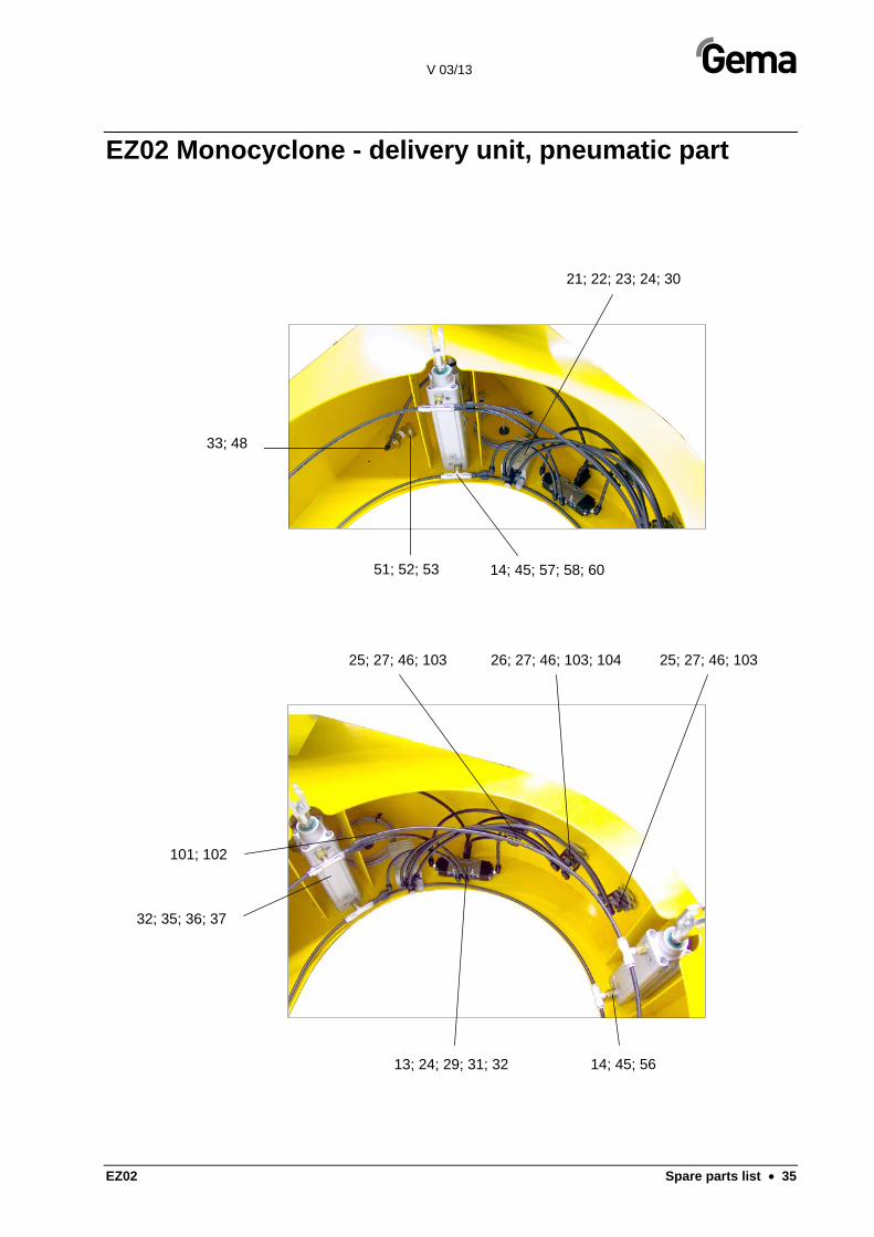
EZ02 Monocyclone - delivery unit, pneumatic part
33; 48
51; 52; 53 14; 45; 57; 58; 60
21; 22; 23; 24; 30
13; 24; 29; 31; 32
32; 35; 36; 37
25; 27; 46; 103 26; 27; 46; 103; 104 25; 27; 46; 103
101; 102
14; 45; 56
V 03/13
36 • Spare parts list EZ02
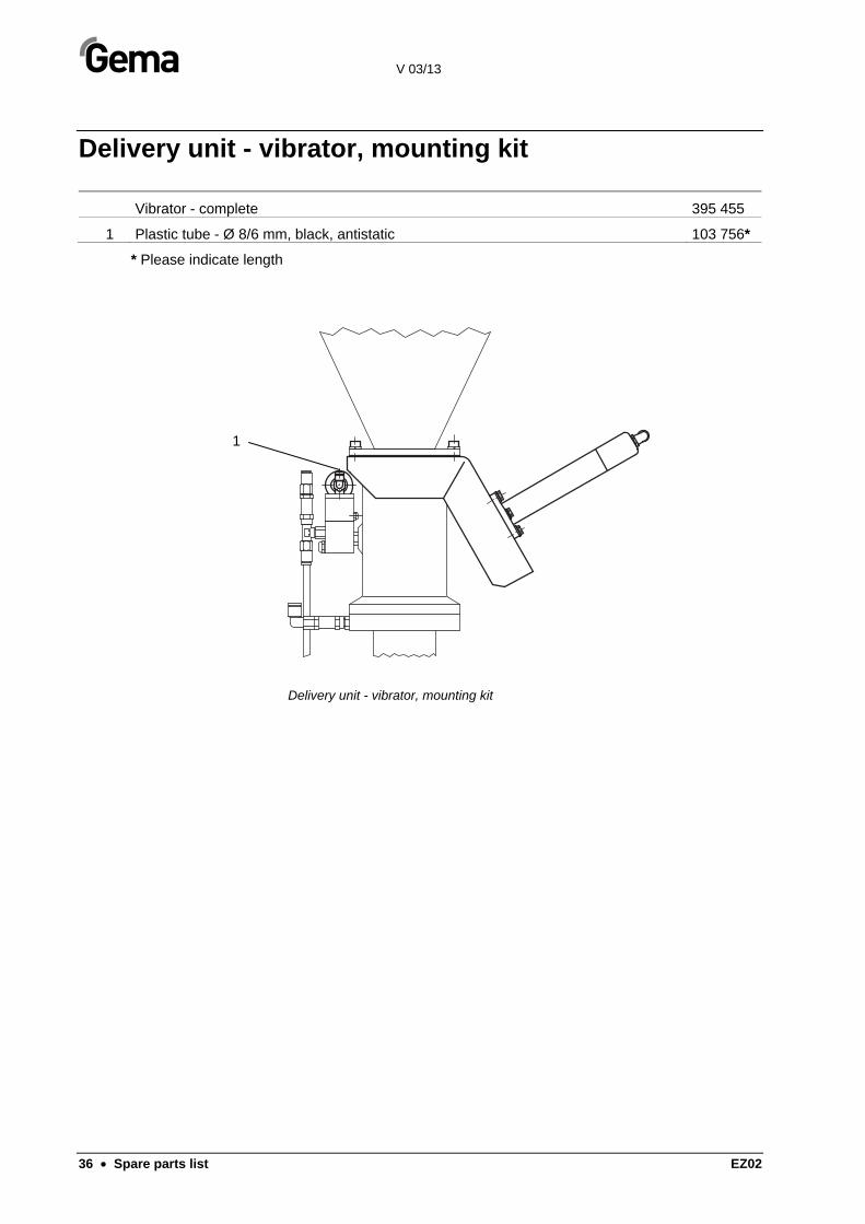
Delivery unit - vibrator, mounting kit
Vibrator - complete 395 455
1 Plastic tube - Ø 8/6 mm, black, antistatic 103 756*
* Please indicate length
Delivery unit - vibrator, mounting kit
1

V 03/13
EZ02 Spare parts list • 37
Sieve insert
Sieve insert complete – 600 μm 392 499
Sieve insert complete – 400 μm 395 340
The sieve is composed of following parts:
1 Supporting ring 392 472
2 Clamping ring 392 480
3 Sieve mesh – 600 μm 105 180
3 Sieve mesh – 400 μm 105 171
4 Grounding spring 392 464
6 Screw 248 568
Sieve insert

V 03/13
38 • Spare parts list EZ02
Dense phase conveying - PT06
Dense phase conveying PT06 - complete 372 820
1 Flange 372 803
2 Pipe bend 372 811
3 Intermediate hopper 372 838
4 Rundown cone 372 846
5 Bezel - Ø 1,9 mm 372 900
13 Pinch valve - NW 65 258 520
13.1 Sleeve 011 576#
14 Servo valve - 1/8"- NW 5.5 258 512
15 Connector IG - G1 258 539
21 Non-return valve unit - 1/8"-1/8" 202 240
22 Silencer - 1/8" 251 305
23 Elbow joint - 1/8"-Ø 8 mm 253 987
24 Elbow joint - 1/8"-Ø 8 mm 203 050
25 T-connection - 1/8"-1/8"-1/8" 237 760
26 Connection sleeve - 1/8"-Ø 8 mm 236 020
27 Screw-in nipple - 1/8"-Ø 8 mm 246 956
28 Double nipple - 1/8"-1/4" 242 209
29 Plastic tube - Ø 8/6 mm, black 103 756*
30 Spring hook - 60x6 mm 250 694
31 Eyebolt - M6x15 mm 261 122
35 O-ring - Ø 26,7x1,78 mm 241 415
40 Hex. cylinder screw - M8x35 mm 216 526
41 Hex. cylinder screw - M8x20 mm 216 496
42 Hex. cylinder screw - M6x10 mm 214 841
43 Lock washer - M8 215 953
44 Transport hose connection (see "Dense phase conveying - connections"
* Please indicate length
# Wearing part

V 03/13
EZ02 Spare parts list • 39
Dense phase conveying - PT06
44
35
2
430
42
22
5
24
29
14
26
25
21
26
5
27
28
41; 43
42
1
13.1
3
13
15
40; 43 31
21
28
23
40; 43
41; 43
Dense phase conveying - array

V 03/13
40 • Spare parts list EZ02
Dense phase conveying – connections
1 Transport hose connection - Ø 25 mm 258 547
Hose - 25/33 mm 104 604*
Hose clamp - 25-35 mm 226 335
Safety rope - length=200 mm 374 628
2 Hose - Ø 8/6 mm, black 103 756*
* Please indicate length
Dense phase conveying - connections
2
2
1

V 03/13
EZ02 Spare parts list • 41