on the beam radiance of mid-infrared quantum cascade
TRANSCRIPT

O
BI
a
ARRAA
KQLOBBRB
C
h1
Opto-Electronics Review 27 (2019) 161–173
Contents lists available at ScienceDirect
Opto-Electronics Review
jou rn al hom epage : ht t p : / / w ww.journa ls .e lsev ier .com/opto-e lec t ronics rev iew
n the beam radiance of mid-infrared quantum cascade lasers–A review
. Mroziewicz, E. Pruszynska-Karbownik ∗
nstitute of Electron Technology, 32/46 Lotnikow Ave., 02-668 Warsaw, Poland
r t i c l e i n f o
rticle history:eceived 27 December 2018eceived in revised form 29 April 2019ccepted 2 May 2019vailable online 8 June 2019
eywords:
a b s t r a c t
Lasers emitting mid-infrared (MIR) beams have become indispensable for spectroscopy, free space com-munication or remote security measures. To the one of the most promising families of the lasers suitablefor these applications certainly belongs a group of the Quantum Cascade Lasers (QCL). However, amongthe conditions they must satisfy there is a high enough radiance of the beam they emit. Radiance dependsin a complicated way on the laser output power and optical quality of the laser beam. This paper has beendevoted to a description and a short analysis of the factors that decide about radiance of so far developed
uantum cascade lasersaser arraysutput poweream quality factorseamadiance
QCLs. Literature concerning both single devices and QCL arrays operating in beam combining systemshave been examined and results described. The survey may be useful for estimation of how far the QCLshave come of age.
© 2019 Association of Polish Electrical Engineers (SEP). Published by Elsevier B.V. All rights reserved.
rightness
ontents
1. Introduction . . . . . . . . . . . . . . . . . . . . . . . . . . . . . . . . . . . . . . . . . . . . . . . . . . . . . . . . . . . . . . . . . . . . . . . . . . . . . . . . . . . . . . . . . . . . . . . . . . . . . . . . . . . . . . . . . . . . . . . . . . . . . . . . . . . . . . . . . . . 1622. Scaling up radiance of a single QCL . . . . . . . . . . . . . . . . . . . . . . . . . . . . . . . . . . . . . . . . . . . . . . . . . . . . . . . . . . . . . . . . . . . . . . . . . . . . . . . . . . . . . . . . . . . . . . . . . . . . . . . . . . . . . . . . . . . 163
2.1. Output power of a single QCL . . . . . . . . . . . . . . . . . . . . . . . . . . . . . . . . . . . . . . . . . . . . . . . . . . . . . . . . . . . . . . . . . . . . . . . . . . . . . . . . . . . . . . . . . . . . . . . . . . . . . . . . . . . . . . . . . . 1632.1.1. Linewidth and tuning of QCLs. . . . . . . . . . . . . . . . . . . . . . . . . . . . . . . . . . . . . . . . . . . . . . . . . . . . . . . . . . . . . . . . . . . . . . . . . . . . . . . . . . . . . . . . . . . . . . . . . . . . . . . .165
2.2. Scaling up the radiance by minimizing the value of M2 factor . . . . . . . . . . . . . . . . . . . . . . . . . . . . . . . . . . . . . . . . . . . . . . . . . . . . . . . . . . . . . . . . . . . . . . . . . . . . . . . . 1652.3. MOPA QCLs . . . . . . . . . . . . . . . . . . . . . . . . . . . . . . . . . . . . . . . . . . . . . . . . . . . . . . . . . . . . . . . . . . . . . . . . . . . . . . . . . . . . . . . . . . . . . . . . . . . . . . . . . . . . . . . . . . . . . . . . . . . . . . . . . . . . . 1662.4. Photonic crystal (PC) DFB QCLs . . . . . . . . . . . . . . . . . . . . . . . . . . . . . . . . . . . . . . . . . . . . . . . . . . . . . . . . . . . . . . . . . . . . . . . . . . . . . . . . . . . . . . . . . . . . . . . . . . . . . . . . . . . . . . . . 167
3. QCL arrays . . . . . . . . . . . . . . . . . . . . . . . . . . . . . . . . . . . . . . . . . . . . . . . . . . . . . . . . . . . . . . . . . . . . . . . . . . . . . . . . . . . . . . . . . . . . . . . . . . . . . . . . . . . . . . . . . . . . . . . . . . . . . . . . . . . . . . . . . . . . . 1683.1. Internal phase-coupling of the laser array modes . . . . . . . . . . . . . . . . . . . . . . . . . . . . . . . . . . . . . . . . . . . . . . . . . . . . . . . . . . . . . . . . . . . . . . . . . . . . . . . . . . . . . . . . . . . . . 1683.2. Internally uncoupled multi-wavelength DFB QCL arrays . . . . . . . . . . . . . . . . . . . . . . . . . . . . . . . . . . . . . . . . . . . . . . . . . . . . . . . . . . . . . . . . . . . . . . . . . . . . . . . . . . . . . 1683.3. Multi-wavelength high power MOPA QCL arrays . . . . . . . . . . . . . . . . . . . . . . . . . . . . . . . . . . . . . . . . . . . . . . . . . . . . . . . . . . . . . . . . . . . . . . . . . . . . . . . . . . . . . . . . . . . . . 168
4. Beam combining as a way to increasing radiance of QCLs arrays . . . . . . . . . . . . . . . . . . . . . . . . . . . . . . . . . . . . . . . . . . . . . . . . . . . . . . . . . . . . . . . . . . . . . . . . . . . . . . . . . . . . 1694.1. Coherent beam combining (CBC) . . . . . . . . . . . . . . . . . . . . . . . . . . . . . . . . . . . . . . . . . . . . . . . . . . . . . . . . . . . . . . . . . . . . . . . . . . . . . . . . . . . . . . . . . . . . . . . . . . . . . . . . . . . . . . 169
4.1.1. CBC presented with aid of the Michelson cavity . . . . . . . . . . . . . . . . . . . . . . . . . . . . . . . . . . . . . . . . . . . . . . . . . . . . . . . . . . . . . . . . . . . . . . . . . . . . . . . . . . . . 1694.1.2. CBC in the Y-junctions tree arrays . . . . . . . . . . . . . . . . . . . . . . . . . . . . . . . . . . . . . . . . . . . . . . . . . . . . . . . . . . . . . . . . . . . . . . . . . . . . . . . . . . . . . . . . . . . . . . . . . . . 1704.1.3. External cavity QCLs with Dammann gratings . . . . . . . . . . . . . . . . . . . . . . . . . . . . . . . . . . . . . . . . . . . . . . . . . . . . . . . . . . . . . . . . . . . . . . . . . . . . . . . . . . . . . . 170
4.2. Non-coherent beam combining (WBC) . . . . . . . . . . . . . . . . . . . . . . . . . . . . . . . . . . . . . . . . . . . . . . . . . . . . . . . . . . . . . . . . . . . . . . . . . . . . . . . . . . . . . . . . . . . . . . . . . . . . . . . . 1704.2.1. External cavity systems in Littman configuration . . . . . . . . . . . . . . . . . . . . . . . . . . . . . . . . . . . . . . . . . . . . . . . . . . . . . . . . . . . . . . . . . . . . . . . . . . . . . . . . . . . 1704.2.2. DFB QCL arrays exploited in the ECL configuration. . . . . . . . . . . . . . . . . . . . . . . . . . . . . . . . . . . . . . . . . . . . . . . . . . . . . . . . . . . . . . . . . . . . . . . . . . . . . . . . . .171
5. Summary and conclusions . . . . . . . . . . . . . . . . . . . . . . . . . . . . . . . . . . . . . . . . . . . . . . . . . . . . . . . . . . . . . . . . . . . . . . . . . . . . . . . . . . . . . . . . . . . . . . . . . . . . . . . . . . . . . . . . . . . . . . . . . . . . 171
CRediT authorship contribution statement . . . . . . . . . . . . . . . . . . . . . . . . . . . . . . . . . .Acknowledgements . . . . . . . . . . . . . . . . . . . . . . . . . . . . . . . . . . . . . . . . . . . . . . . . . . . . . . . .References . . . . . . . . . . . . . . . . . . . . . . . . . . . . . . . . . . . . . . . . . . . . . . . . . . . . . . . . . . . . . . . . . .
∗ Corresponding author.E-mail address: [email protected] (E. Pruszynska-Karbownik).
ttps://doi.org/10.1016/j.opelre.2019.05.001230-3402/© 2019 Association of Polish Electrical Engineers (SEP). Published by Elsevier
. . . . . . . . . . . . . . . . . . . . . . . . . . . . . . . . . . . . . . . . . . . . . . . . . . . . . . . . . . . . . . . . . . . . . . . . . . . 171 . . . . . . . . . . . . . . . . . . . . . . . . . . . . . . . . . . . . . . . . . . . . . . . . . . . . . . . . . . . . . . . . . . . . . . . . . . . 171
. . . . . . . . . . . . . . . . . . . . . . . . . . . . . . . . . . . . . . . . . . . . . . . . . . . . . . . . . . . . . . . . . . . . . . . . . . . 172
B.V. All rights reserved.

1 / Opto
1
oslTlit(1tgaGwrod
aedmCt
rraaTwrde
telfof
ltbtfudra[rEiatomdie(
62 B. Mroziewicz, E. Pruszynska-Karbownik
. Introduction
Appearance of quantum cascade lasers (QCLs) in 1994 [1]pened up a long time expected feasibilities for development ofemiconductor lasers capable to emit infrared radiation in a wave-ength range extending from around 3 �m [2] to terahertz [3,4].his ability remarkably enhances applications of semiconductorasers in spectroscopy, free space communications and security,ncluding directed infrared countermeasure systems [5–7]. Spec-roscopy takes an additional advantage that in the mid-infraredMIR) wavelength band the emission linewidth can be as low as2 kHz [8]. The 3 �m wavelength limit arises due to a small conduc-ion band offset for QCLs made of classic InGaAs/InAlAs structuresrown on InP substrates. That can be overcome to some degree bypplication, for instance, InAs/AlSb compounds grown on InAs oraSb [2], but this technology is still immature. Extending the QCL’savelength to terahertz region meets a number of difficulties and
equires cooling of the device. Solutions are found either by devel-ping special waveguides [3] or employing intra-cavity terahertzifference-frequency mixing in a dual-wavelength QCLs [4].
Advancements in physics, fabrication technology, propertiesnd applications of the QCLs have been too important and inter-sting to be left unpublicized. As a result, the number of papersevoted to various aspects concerning these devices is now enor-ous. In particular, the review papers like those by P. Rauter and F.
apasso [9] or M. Razeghi et al. [10] and many more [11–13], bothhe older and new ones, give a very good survey of the subject.
The purpose of this paper is to draw attention to QCL’s beamadiance (termed also brightness) as this feature is in practice theeal criterion of the laser performance. That is particularly true forpplications that require the presence of high power laser beamst remote locations. Radiance becomes then a laser figure of merit.his topic has been already elucidated by P. Shukla et al. [14] but itas mainly devoted to various types of lasers designed for mate-
ial processing. In addition, the content of that paper has left someoubts concerning definitions of the laser beam radiance and, thusncouraged us to undertake discussion of the subject.
Our paper concentrates on the analysis of MIR QCL’s parametershat decide about their radiance and are deducible from laser prop-rties described in the literature. We have paid special attention toasers operating within spectral atmospheric windows extendingrom 4.5 to 5.5 �m and from 8 to 9 �m as they are relatively freef absorption by water (see Fig. 1) and, therefore are most suitableor the systems operating at remote locations.
In addition, the wavelengths corresponding to the first windowend itself to production of high power QCLs. That is because pho-on energy at (275 meV for 4.5 �m) comprises a large fraction of theand offset of conventional lattice matched AlInAs/InGaAs struc-ures (520 meV) and highly strained InP-based material can be usedor production of high-performance QCLs emitting at � < 5.5 �msing MOCVD or MBE layer growing processes [15–18]. The intro-uction of the strain leads to higher barriers and, as a consequence,educes carrier leakage and changes the type of leakage from leak-ge to continuum to shunt-like leakage within the active region19]. The QCLs emitting around 4.5 �m wavelengths dominate inesearch that brings lasers with still scaling up the WPE (Wall-Plugfficiency) and the output power. This remark by no means disqual-fies the 8–9 �m, QCLs also found to be very useful in mentionedbove applications. In any case, applications like gas sensing foroxic industrial chemicals and explosives or detection and rangingr free space optical communications the AlInAs/GaInAs structuresatched to the InP substrates and grown mainly by MOVPE process
ominate in these applications. This remark by no means disqual-fies MBE that is still being exploited and delivers excellent QCLsmitting for instance total powers of 4.5 W at room temperatureRT) when pulsed and 2 W CW (continuous wave) with a wall plug
-Electronics Review 27 (2019) 161–173
efficiency of 16% or 10%, respectively [16], and, thus they are inno way inferior to the best MOVPE-grown QCLs [18]. In any case,the QCLs technology requires careful optimization of the epitaxialprocess. A non-equilibrium Green’s function modelling has provedto be very helpful in examining electronic transport and opticalproperties of the investigated epitaxial structures [20–22].
Parameters used to describe the performance of semiconductorlasers are, apart from the wavelength, quite often limited to theoutput power, the regime of the work: pulsed or continuous wave(CW), and the maximal operational temperature. The laser beamitself remains undescribed although as it has been said above, forapplications like remote optical sensing it is essential to be ableto send the beam of high enough power to a long distance. Thisdeficiency may be partly made up by indicating the so-called beamparameter product (BPP):
BPP = D0·�. (1)
Here, D0 is the near-field beam waist width and � is the beam diver-gence angle (assuming that it is close to Gaussian). In reality, thebeams generated by semiconductor edge emitting lasers both diodeand QCL are strongly divergent, radially asymmetric, and by nomeans can be treated in terms directly related to Gaussian. Despiteits deficiency, the BPP factor may sufficiently well characterize theprofile of the laser beam that is to be used for applications like weld-ing or cutting. However, much more sophisticated measures haveto be considered when the beam is to reach some remote locations.Then, we must know the beam distribution in space and term “radi-ance” has to be evoked. It is worthwhile to mention that quite oftenterm “brightness” is used instead of radiance despite the fact thatwe deal with infrared wavelengths. Definition and meaning of radi-ance have been discussed in Refs. 23 and 24. Here we shall quoteonly formulas most frequently encountered in the papers dealingwith the problems discussed in the present paper.
Thus the radiance can be expressed by:
Le = CP
�2M2x M2
y
, (2)
where P is the output power, C is some constant dependent on thedefinition of the beam cross-section dimensions and divergence[25], � is the wavelength, M2 is the beam distortion measure inrespect to the Gaussian one and, directly from this definition, canbe expressed by the formula:
M2 = �
4�D0�, (3)
where D0 is the beam waist width and � is the divergence angle ofthe real laser beam [24].
Because there are no unquestioned definitions of D0 and � fornon-Gaussian beams, it recommended determining the value of M2
based on the beam matrix P containing second-order moments ofthe Wigner distribution:
P =
< x2 >
< xy >
< x�x >
< x�y >
< xy2 >
< y2 >
< y�x >
< x�y >
< x�x >
< y�x >
< �2x >
< �x�y >
< x�y >
< y�y >
< �x�y >
< �2y >
. (5)
Then, the beam quality parameter M2 is expressed by the fol-lowing formula [26]:
M2 = 4�(det P)
13 . (4)
�
The beam shape and corresponding M2 factor have become veryimportant after QCLs came of age and can now operate at room tem-perature and high output power. The latter and the wide spectral

B. Mroziewicz, E. Pruszynska-Karbownik / Opto-Electronics Review 27 (2019) 161–173 163
F veleng[ indica
ri
losi
2
2
ttoaAoCpaaetodthranntsswtlttct
ig. 1. Diagrams showing transmission spectrum of the atmosphere in the MIR wahttp://www.gemini.edu/sciops/telescopes-and-sites/observing-coditions]. Arrows
ange in which they operate made them suitable for applicationsn free space optics if their beams are of high enough radiance.
Unfortunately, the value of the radiance in case of discrete QCasers is rarely quoted and can be only deduced from the citedutput power and M2 factor, providing that the latter has been mea-ured [27]. Some rough numbers found in the literature are quotedn Table 1.
. Scaling up radiance of a single QCL
.1. Output power of a single QCL
High output power is a fundamental parameter in the augmen-ation process of the QCL’s radiance [see expression (2)]. Scaling uphe laser output power can be attained by increasing the numberf the active region stages, sheet carrier density per stage in thective region or simple enlargement of the laser chip dimensions.ll these ways can be exploited to achieve high peak power in pulseperation but most of them are of limited usefulness in the case ofW devices because of their active region self-heating. A high tem-erature of the active region is detrimental to laser performances it leads to the higher threshold current, lower slope efficiencynd, therefore to lower the wall-plug efficiency (WPE), which inffect diminish maximum optical power of the laser. As these fac-ors are particularly important in case of the QCLs designed to beperated in the CW mode, the active region in such lasers should beesigned to suppress the undesirable high-temperature effects ando provide effective heat dissipation from that region. It should be,owever, remembered that enlargement of the waveguides widthesults in lower beam quality due to excitation of a multimode oper-tion. On the other hand, the increase in the laser cavity length doesot cause any increase in the active region temperature and doesot affect the beam quality. Thus, the advantage of this approach ishat high power can be obtained from narrow devices which are lessubject to self-heating and are therefore less sensitive to limitationsuch as the thermal conductivity of the sub-mount. In the range forhich there is the gain not saturated, the WPE in pulsed opera-
ion depends theoretically on cavity length only through mirrorosses, so it can be maximized for a given cavity length by deposi-
ion of a facet coating that will produce the same mirror losses ashose for the optimal length. In result, the output power of QCLsan be increased while maintaining high WPE by using long cavi-ies and optimized AR coating [28]. It is to be noted, however, thatth ranges 4–5.5 �m and 7–10 �m calculated using the ATRAN modelling softwarete most common wavelengths of the investigated QCLs.
the CW WPE strongly depends on the laser slope efficiency the lat-ter being the result of inter alia injection efficiency inherent to themechanism of QC laser operation and losses in the laser structure.In particular, the slope efficiency is decreased by carrier leakagethrough the inactive stages or increasing of the electron backfillingthe lower laser levels. This efficiency clearly depends on thermallosses in the laser chip and its value is also related to the laserlateral beam mode content. The last word has not yet been said,however, just recently [29] it was found that old-fashioned GaAsQCLs can be still improved by deepening all the GaAs wells in thelaser structure, both in the active region and injectors. The effectwas attained by increasing amount of indium in these wells andresulted in devices that could operate up to 323 K.
For high power devices, the situation may be complicated bynon-uniform gain saturation due to variations in longitudinal inten-sity profile along the waveguide. This may have a detrimental effecton the WPE in case of very long devices (i.e. longer than centimetreones) and such optimization does not lead to high power lasers.Although the losses can be reduced to a certain extent by optimiz-ing the laser facet coatings, this way turned out not very effectivefor high power devices [30]. In any case, mirror losses must be opti-mized with regard to WPE by deposition of a facet coating properlyadjusted to the cavity length.
It is obvious that heat dissipation from the laser active regiondepends strongly on the laser geometry. With reference to QCLs,their structures can be grouped as shown in Fig. 2.
Most QCL configurations described in the literature have beendesigned in form of the index-guided narrow waveguides (i.e. ofthe width not exceeding 10 �m) to avoid high order modes andimprove heat dissipation through side waveguide walls. The opticalwaveguide, in general, should provide low optical losses and a largeoverlap factor of the optical mode with the gain medium. An inter-esting configuration of a high power QCL has been described in Ref.31 and shown in Fig. 2b). Its design is an alternative to the typicaldesign called double channel [Fig. 2a)]. A narrow width low-ridgeconfiguration is exploited for achieving high peak pulsed power.The basic mechanisms that play here a role are changes in the lat-eral current spreading in the layers above the active region. Thenarrow waveguide can take in addition an advantage of the current
spreading that leads to a lower threshold current density due to themechanism of their operation. But the narrow waveguide QCLs, ingeneral, suffer poor heat sinking because of the low heat spreadingarea. A solution is the buried double channel ridge heterostructure
164 B. Mroziewicz, E. Pruszynska-Karbownik / Opto-Electronics Review 27 (2019) 161–173
Table 1The QCL’s radiance values selected from the literature to illustrate chronologically the achievable magnitude of this parameter.
Year Ref. No Peak power [W] M2 � [�m] Le [Mwcm−2 cm-1] Operation Design
2010 66 9 3.5 4.36 3.86 Pulse Broad area PC DFB2010 80 0.3 < 1.4 4.48 1.73 CW CBC in the Michelson cavity2010 91 30 <2 4.6 35.4 Pulse WBC of QCL array beams in the
external cavity system2011 85 0.5 (x) 1.2 (y) 1.6 4.65 1.38 CW Beam combining with
Dammann grating2011 38 2.5 (1.36) (x) 1.06(y) 1.03 4.65 10.6 Pulse (CW) Buried heterostructure2013 65 4 1.6-1.8 8.1 3.35 – 4.05 Pulse MOPA tapered2013 64 2.5–3.8 2.08 2.25 9.5 1.40 1.87 Pulse MOPA tapered (FWHM 1◦)
(FWHM 2◦)2013 61 2 1.3-1.6 9.2-9.7 0.63 – 1.6 Pulse MOPA tapered
2014 531.251.2
1.24-1.983.85
8.70.07 – 0.720.34
Pulse Tilted front facet2015 55 203 5 4.8 156 Pulse Angled cavity2016 41 23.5 (x) 6 (y) 1.27 4.55 14.89 Pulse Gain-guided
F el high
(arpwtcsWeiaTHopbwbtCAw[oIen
ig. 2. Schematic drawings of the currently existing QCL’s designs: a) double chann
BH) [see Fig. 2c)] having a narrow width of the ridge [32]. Thatpproach turned out to be the most effective way to achieve theequired parameters and in addition to maximize the heat dissi-ation from the waveguide core [33–35]. These features combinedith improvements in active region design dramatically increased
he WPE in recent years. The active-region designs that reduce thearrier leakage evolved from the deep-well design [36] to so-calledhallow wells [33] and so-called step-taper active region [18,19].
hile in 2009, the QCLs emitting in the 4.6 �m window deliv-red 3 W CW with WPE of 12.7% at 293 K [34], two years latern 2011, the attained CW WPE at RT for InP based QCLs, emittinground 4.9 �m, was of 21% and raised to 27% in pulse operation [37].he maximum CW RT power output of these lasers reached 5.1 W.owever, due to such enlargement of the waveguides, the laserperation must be multimode and, as mentioned above, results inoor beam quality. Xie et al. [38] showed that deterioration of theeam quality of QCL emitting about 4.6 �m starts for the waveguideidth of 7 �m. Record high pulse power of 120 W was achieved
y enlarging the ridge width up to 400 �m although at the sameime the WPE showed some decrease [39]. Whereas, the record ofW single-mode power from broad area (BA) QCL is 1.36 W [38].
more detailed analysis of the BA structures has shown that aide active region does not prohibit the RT CW QCL’s operation
40]. Lasers with the active region 30 �m wide, and consisting of
nly 10 cascades, emitted 0.6 W CW at temperatures close to RT.n order to achieve this, it was necessary to provide conditions forffective heat sinking from the top contact and to limit the thick-ess of the active region by restricting the number of cascades. Themesa, b) narrow low ridge, c) buried ridge waveguide, d) high-power gain-guided.
laser should be mounted epi-down applying well known alreadymethods and materials. Temperature distribution in the BA QCLsdescribed in Ref. 40 leads to the conclusion that temperature risein the active region scales linearly with the heat density, but issquared with the active region thickness. Therefore, it is adven-turous to decrease cascade number even if that will increase heatdensity due to the rise of the threshold current density. Thus, theincrease of the laser ridge width can be considered as a promis-ing route to scaling the laser output power. Unfortunately, at thisapproach, the beam profile degrades quickly as higher order lateralcavity modes are excited. In result, the BA QCLs tend to show multi-ple peaks in the far-field profile due to exciting higher order lateralmodes and a “rabbit ear” shape in the far field is the typical beampattern for BA QCLs. It is so if no special precautions are taken andthe TM polarization facet reflectivity increases with mode index.The broad area QCLs lase in that case on high order modes witha far-field profile consisting of 2 lobes propagating at large anglesfrom the optical axis. Nevertheless, the BA geometry is the moststraightforward approach for power scaling of the QCLs. Due to theincrease in the size of the resonator the output power can be hun-dreds of times higher than in the case of a narrow ridge device.As mentioned above up to 120 W peaks power has been demon-strated in a BA QCL. However, both high output power and goodspatial beam quality of BA QCLs can be achieved only by suppres-
sion of higher order lateral modes. Despite all the drawbacks, theBA QCLs are very interesting because, unlike diode lasers, in gen-eral QCLs have negligible linewidth enhancement factor [31] andtherefore should not suffer from filamentation and consequently
/ Opto-Electronics Review 27 (2019) 161–173 165
ca
godpdTlttbhcptiUo
pTt
mt[tbbmbrmwsd
iiina[
al
2
eaat2p[etfrh
tb
B. Mroziewicz, E. Pruszynska-Karbownik
ould operate stably in a single transverse mode at currents wellbove threshold.
The lasers described above belong to the group termed “indexuided” adequately to the way the mode structure is formed. Thether type of that process may be “gain guiding”. Gain-guidediode lasers have been known for decades. They generate highower beams but with rather poor quality. In that aspect, the QCL’sesigns demanded a different approach from the described above.herefore, on a special notice deserves described in Ref. 41 ideaeading to high power gain guided QCLs based on the structurehat assures operating at fundamental optical mode. In that struc-ure [see Fig. 2d)], distribution of the current in the active regionecame strongly non-uniform and gain profile corresponding to theorizontal current density spreading led to gain guiding and effi-ient optical mode selection. Described lasers emitted 23.5 W peakower at RT and 1% duty cycle. Due to their efficient optical guiding,hey emitted a single lobe beam with a ratio of 1:7 between the hor-zontal and vertical axis. The estimated value of Mx
2 was around 6.nfortunately, the output beam characteristics depended stronglyn the current.
In conclusion, it is quite difficult to develop QCLs emitting a highower beam and to avoid at the same time an increase of the M2.hus, achieving solely emission of high output power is not enougho attain a laser beam of high radiance.
Regardless of the laser structure, heat generated in the deviceust be effectively conducted away. This necessity has impelled
o extensive research on heat spreading in semiconductor lasers42–44]. Particular effort has been devoted to soldering process ofhe laser chips to heat spreaders. This task has been challenging asoth the heat conductivity of the soldered materials and the strainetween them had to be taken into account. Significant improve-ent was achieved when so-called epi-down soldering technique
ased on using a hard solder (AuSn) has been mastered [42]. Anyesearch on these problems obviously demanded development ofeasurement techniques capable to evaluate temperature profilesithin the laser active region. In that aspect, thermo-reflectance
pectroscopy turned out to be very helpful and has been studied inetails [45,46].
The obvious solution leading to scaling the laser output powers to operate it in a pulse regime and that is a common practice. Its important that in a pulse mode operation the laser output powerncreases linearly with the width of the device. Still, it should beoticed that an intra-pulse modal instability and beam steering in
pulse operated QCLs may take place due to lateral hole burning47].
Recapitulating the remarks above one should be aware that inddition to edge emitting lasers there exists a plethora of anotheraser configuration as described below.
.1.1. Linewidth and tuning of QCLsThe QCLs as a source of penetrating signals provide very pow-
rful technical solutions applicable to spectroscopy used at remotellocations. They can be designed to operate in a single mode with
very narrow linewidth and sufficiently high pulsed or CW powerhat satisfy spectroscopy requirements. For instance, the power of.4 W CW has been attained in a single lobe with a side mode sup-ression ratio (SMSR) around 30 dB in the current range of 1–1.7 A48]. As mentioned above, the linewidth as low as of 12 kHz wasstimated for a stabilized QCL [8]. The required single mode opera-ion of the laser is usually achieved by implementing the distributedeedback (DFB) configuration. For a CW operating DFB QCL, a free-unning frequency stability of 150 kHz over a 15 ms time interval
as been observed [49].Tuning of the laser wavelength is absolutely necessary for spec-roscopy applications. The simple DFB QCLs can be tuned eithery changing the supply current or temperature. The best results
Fig. 3. Schematic of a multi-section sampled grating DFB QCL.
obtained for the current tuning of 4–5 �m QCLs were of the orderof 5 cm−1 [48]. Temperature tuning is slightly more effective andwas executed over a range of 6 cm-1 for DFB QCLs operating at 9 �m.This figure could be multiplied by combining lasers to form an arraywith individually supplied lasers [50]. A much better solution relieson a multi-section sampled grating DFB (SG DFB) technology [51].An example of such solution is displayed in Fig. 3. It consists of twosections each containing gratings with sampling periods Z1 andZ0, respectively. Both sections utilized a 30-period grating whichwas sampled 3 times. The sampling periods were appropriatelyadjusted for different sections to obtain uniform injection tuningeffects. The obtained tuning range was up to 50 cm-1.
It is true that internal tuning range limitations connected withDFB QCL structures can be overcome by applying configurationsbased on external cavity feedback. The 303 cm−1 tuning range wasobtained for a DFB QCL operating at the central wavelength of 8 �mwith a maximum optical power of 200 mW [52]. However, thesesystems require external optical components and their tuning isof a mechanical nature. As such, it is slow and dependent on themechanical precision.
2.2. Scaling up the radiance by minimizing the value of M2 factor
As it has been shown above, the most straightforward approachleading to scaling up the QCL output power is increasing the geo-metric dimensions of the laser. However, simply widening the lasercavity leads to poor beam quality and multimode spectrum arisingfrom high-order transverse modes.
If a high power QCL is engineered by the increase of the devicearea, its beam profile usually degrades. It is because higher-orderlateral cavity modes are excited and this results in the increase ofM2. An exception has been described above with reference to gainguided QCLs, but the obtained results demand further improve-ments. In any case, high output power is not enough to obtain thelaser beam of high radiance. Making simply the resonator widerbut without changing its shape would induce a degradation of thebeam quality. In fact, a mentioned above rabbit-ear-shaped far fieldis the typical beam pattern for BA QCLs.
An interesting solution to this problem has been found by tilt-ing the laser front mirror (facet) with respect to the optical axisof the cavity [53]. The non-perpendicular cavity has been realizedby a specific etching of the front mirror that makes them nonpar-allel. Such mirrors induce asymmetric light intensity distributionalong the laser cavity and hence most of the light is being emit-ted through only one facet. In the cited work, emission throughthe tilted front facet has shown a lower beam divergence, sup-pression of higher order lateral modes of BA QCLs, as well as theincrease of slope efficiency and of the maximum peak power. The
◦
optimal tilting angle was around 17 and the method was effectiveto the waveguides of about 60 �m wide. The peak output powerof 1.3 W in a single lateral mode has been obtained and the lasersshowed a nearly-diffraction-limited beam with an FWHM of 8.3◦.
166 B. Mroziewicz, E. Pruszynska-Karbownik / Opto-Electronics Review 27 (2019) 161–173
Fig. 4. Principle of a” tilted mirror” QCL (a) and two exemplary types of” angled” QCLs (b) (based on ideas presented in Refs. [53–55]53–55).
gns de
Tor
tiF
afvwuAttbvciTcodoprad
tntDosttL
Fig. 5. MOPA and tapered laser desi
he calculated M2 value depended on the current and was aroundf 1.24–1.98 resulting in the radiance of 0.07−0.72 MW cm−2 sr-1,espectively.
A similar approach but with two laser facets tilted with respecto optical axis was proposed for DFB QCLs and termed “angled cav-ty” [54,55]. The concept of both solutions has been displayed inig. 4.
As a result it has been proved that angled waveguides, as wells DFB and photonic crystal DFB QCL angled cavity with parallelacets, bring power scaling with good beam quality and so pro-ide a high radiance. However, it should be noted that these lasersork only in the pulse regime, which still does not diminish theirsability for some applications, such as molecular spectroscopy.s the angle increases all modes experience increased losses, but
he higher order lateral mode losses intrinsically increase fasterhan the fundamental mode. This is due to the nonlinear relationetween the penetration depth and the incidence angle and pro-ides lateral mode discrimination. For any wavelength, exists aritical angle for suppressing the higher order modes. This angles dependent on the side wall shape, its roughness, and materials.he study on the tilt angle was carried out on QCLs with doublehannel waveguide emitting around 5 �m [55]. The tilt angle wasn the order of 12◦ and a peak power of 203 W was obtained at theriving current of 136 A for a duty cycle of 0.02%. At a driving currentf 120 A, the M2 = 5 was obtained with an FWHM of 3◦. The outputower at this current was 180 W which translates to a record highadiance Le of 156 MW cm−2 sr-1. This ultrahigh radiance value for
QCL may be considered as a proof that the single lobed far field isue to the angled cavity.
Combining the sampled grating solution with the surface emit-ing concept one can obtain an interesting result in form of aarrow beam as described in Ref. 56. The quoted laser has beenermed “grating-coupled-surface emitting QCL” (GCSE). A 2nd orderFB/DBR Au-semiconductor grating was used for feedback andutcoupling. The DFB grating was terminated on each end by
econd-order DBR gratings. Grating periods have been adjustedo generate a single mode beam which was perpendicular tohe active region plane and that has led to surface emission.aser operation has been made possible by inherent suppressionvised to emit high radiance beams.
of the antisymmetric modes and therefore depended on phe-nomenon connected with the resonant coupling of the guidedoptical mode to the antisymmetric surface plasmon mode of ametal–semiconductor grating. The laser operated in a symmetricgrating mode at 4.75 �m wavelength and emitted around 0.4 Win a single lobe of 0.048 ◦FWHM. The emission linewidth wasof 0.43 nm. It was found that such laser configuration does notaffect the laser output power while collimates the beam. Furtherimprovements of this device concept are expected.
2.3. MOPA QCLs
Laser configuration termed MOPA (master oscillator poweramplifier) is one of the most promising approaches to scaling upsemiconductor laser beam radiance in the pulse regime. They owethis to combining a seed i.e. the laser that generates high opticalquality signals with an amplifier that if properly designed, ampli-fies the output power without significant distortion of the outputbeam. The idea of MOPA structures originated at times when choiceof seeds and power amplifiers was at the beginning restrictedto diode laser structures. It became particularly interesting afterpower amplifier section took the form of so-called “tapered waveg-uides”.
The first proofs-of-concept of the QCL MOPAs were demon-strated by Trocolli et al. [57] and they soon found followers. Theinvestigated devices have been of different geometry dependingon the expected laser properties. However, all of them consisted oftwo parts: a seed operating as a DFB laser and a section of a poweramplifier (PA). Their layouts have been sketched in Fig. 5. The PAsection has been at the beginning rectangular, afterwards “tapered”to exploit many advantages of this geometry among them the pos-sibility of a single lateral mode operation. In high power lasers withthe broader active area the PA section mitigates the effect of gainsaturation on reducing the single-pass gain. To prevent lasing in thissection the front facet can be AR coated or cleaved at a small angle
relative to the normal with regard to the propagation direction [seeFig. 5a)]. Depending on the version, the seed and PA can be electri-cally connected or supplied separately [58] (types b and c in Fig. 5).A disadvantage of electrical isolation between the MOPA sections is
B. Mroziewicz, E. Pruszynska-Karbownik / Opto-Electronics Review 27 (2019) 161–173 167
F [66])
tccttphhittMatpbtsskaa[4paioTtPmaosrtqliiotiitscd
ig. 6. Configurations of (a) a photonic crystal DFB QCL (based on idea presented in
he necessity of double synchronized supplying. In the electricallyonnected version, the whole MOPA configuration with tapered PAan be considered as a “tapered laser”. Concluding, it is obvioushat configuration of the tapered MOPA QCLs offers many solutionso satisfy properties demanded from these devices i.e. high out-ut power and/or single transverse mode operation that leads toigh radiance. Their geometry allows in general for suppression ofigher-order lateral modes because of taper acute angle while the
ncrease in the volume of the gain material over that of conven-ionally designed ridge devices results in a significant increase ofhe available peak power. Therefore, the sections of the tapered
OPA lasers sketched in Fig. 5 may differ not only in width butlso in length (types c and d). In type e the main purpose of theaper was to increase the device area in order to increase its peakower in low-duty-cycle pulse operation while maintaining goodeam quality. In such devices, the length of the tapered section wasypically more than half of the entire device [59]. The purpose ofhaping the PA in form of a taper may also be reducing optical inten-ity at the output facet to increase optical damage threshold whileeeping self-heating to a minimum for high-performance CW oper-tion. Therefore, the taper width and length, in that case, is kept to
minimum leading to coversion from MOPA to flared waveguide60]. These lasers showed WPE of 16.3% and optical power over.5 W CW in 283 K. They had highly strained active region com-osition and operated at 4.7 �m wavelength. Single-longitudinalnd single-spatial mode tapered pulsed QCLs have been describedn Ref. 61. An evident advantage of a tapered MOPA configurationver typical Fabry-Perot (F-P) cavity has been shown in Ref. 62.he output power of 1.5 W at RT (� =7.26 �m) was obtained forapered MOPA QCLs while only 0.9 W was available from the F-
QCLs made from the same MOVPE on InP grown active regionaterial. The MOPA tapered lasers displayed single longitudinal
nd transverse mode emission which resulted in the beam FWHMf 10◦ in the chip plane. This figure was 3 times higher for the F-Ptructures. Non-linear flaring of waveguides has also been testedecently and although the linearly tapered waveguides producehe greatest output power, convex waveguides lead to better beamuality and consequently greater radiance [63]. In another type of
asers the light emitted by the seed travels only once before leav-ng the device, thus the taper section was used as a monolithicallyntegrated single pass external optical amplifier for obtaining highutput power [64]. The length of the tapered section was chosen sohat the taper angle was of 0.7◦ and the mode expanded adiabat-cally in this section. Thus, the taper was used as a monolithicallyntegrated single pass external amplifier, i.e. a device through which
he light emitted by DFB oscillator travels only once. Although thelope efficiency decreased with increasing taper angle, paradoxi-ally, the threshold current density was also lower for the taperedevices than for the F-P device made from the same material. Thisand (b) photonic crystal surface emitting QCL (based on idea presented in [69]).
has been explained by the fact that threshold current density is alsolower for the tapered devices than for F-P lasers. The 1.0◦ devicesdelivered up to 2.5 W of optical peak in the beam with M2 = 2.0◦.The devices emitted 3.8 W with M2 = 2.25 and had the radiance of1.87 MW cm−2 sr-1 [64].
In attempt to attain a QCL that would emit the beam of possiblylow divergence a MOPA with plasmonic collimator has been devel-oped [65]. The collimator was produced on an InP laser substrate inthe plane of laser facet. It consisted of a second order grating with7.5 �m period. The obtained M2 value was of 1.6 at I = 3.5 · Ith andtherefore the maximal radiance of 4.05 MW cm−2 sr−1 was reached(see Table 1).
2.4. Photonic crystal (PC) DFB QCLs
Although the gain guided QCLs based on a wide active regionand a narrow current injector on the top, attained peak power emis-sion of 23.5 W at RT (see Ref. 41), the problems of the beam qualityand scaling up of the M2 factor have not been solved. In search fornew QCLs configurations that would lead to improvement of boththese parameters a two dimensional photonic crystal structure dis-tributed along the cavity has been proposed and investigated [66].Its configuration is shown in Fig. 6a). Other use of photonic crystals,as shown in Fig. 6b), results in surface emission and the lasers aretermed surface emitting photonic crystal QCLs [69].
The photonic crystal distributed feedback (PC DFB) structuredescribed in Ref. 66 had a form of the rectangular lattice with firstand second order Bragg gratings in the transverse and longitudinaldirections. The aspect ratio of the resulting rectangular structurewas �1/�2 = 2. The cavity facets were tilted at the angle of 140
with respect to the transverse axis of the lattice. At a cavity widthof 100 �m high-power nearly-diffraction-limited operation up to6 W was obtained from the PC DFB QCL. The radiance of a PC DFBlaser increases with increasing cavity width and optimization ofthis parameter is a major concern in the design of high-performanceBA lasers [66]. A 400 �m wide PC DFB QCL emitting at � =4.36 �mwith a total peak power of 34 W at RT based on an optimization ofthe coupling coefficients at the given cavity width and length hasbeen realized, its slope efficiency was around 560 mW/A [66]. TheM2 parameter had value of 2.5 at 1.1 Ith and stayed below 3.4 up to1.51 Ith. The radiance of these lasers was increasing with enlarge-ment of the cavity width. The power output was strongly relatedto the beam quality and single spectral mode operation throughthe selection of transverse and longitudinal coupling coefficientsat a given cavity width and length could be achieved. It is worth-
while noting that QCLs should not suffer from filamentation andthus could operate stably in a single transverse mode at currentswell above threshold. But because of a TM polarization, facet reflec-tivity increases with mode index and broad area QCLs are lasing on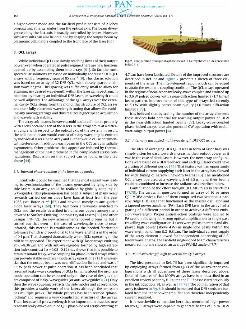
1 / Opto-Electronics Review 27 (2019) 161–173
apgsp
3
posawsaabnaia
wetbtamfia
3
iswr1dQddtitoMatact5rmatthlTr
68 B. Mroziewicz, E. Pruszynska-Karbownik
higher-order mode and the far-field profile consists of 2 lobesropagating at large angles from the optical axis. The beam diver-ence along the fast axis is usually controlled by lenses. Howeverimilar results can also be obtained by shaping the output beam bylasmonic collimators coupled to the front face of the laser [65].
. QCL arrays
While individual QCLs are slowly reaching limits of their outputower, even when operated in pulse regime, there are new horizonspened up by assembling them into arrays [61]. So far, the mostpectacular solutions are based on individually addressed DFB QCLrrays with a frequency span of 85 cm−1 [9]. This classic solutionas based on an array of 32 DFB QCLs with closely spaced emis-
ion wavelengths. This spacing was sufficiently small to allow forttaining any desired wavelength within the laser gain spectrum. Inddition, by heating an individual DFB laser, its wavelength coulde well adjusted. The advantage of the QCL arrays over the exter-al cavity QCLs stems from the monolithic structure of QCL arraysnd their fully electronic wavelength tuning that allows for avoid-ng any moving gratings and thus realizes higher speed acquisitionnd wavelength stability.
The array sub-beams, however, could not be collimated properlyith a lens because each of the lasers in the array emits at a differ-
nt angle with respect to the optical axis of the system. In result,he collimated beam would consist of many wavelengths emittedy individual lasers in the array and all that would cause detrimen-al interference. In addition, each beam in the QCL array is radiallysymmetric. Other problems that appear are induced by thermalanagement of the heat produced in the complicated arrays con-
gurations. Discussion on that subject can be found in the citedbove [44].
.1. Internal phase-coupling of the laser array modes
Intuitively it could be imagined that the most elegant way lead-ng to synchronization of the beams generated by lying side byide lasers in an array could be realized by globally coupling allaveguides. This phenomenon has been a subject of many years
esearch carried out on diode laser bars at least from the year988 (see Botez et al. [67]) and devoted mostly to anti-guidediode laser arrays [68]. They had been afterwards switched toCLs and the results described in numerous papers among themevoted to Surface-Emitting Photonic Crystal Lasers [69] and otheresigns [70–72]. The new achievements looked promising but iturned out that even in the case of wavelengths close to near-nfrared, this method is troublesome as the needed fabricationolerance (which is proportional to the wavelength) is in the orderf 0.1 �m. That changed dramatically when QCLs operating in theIR band appeared. The experiment with QC laser arrays emitting
t � =8.36 �m and with anti-waveguides formed by high refrac-ion index contrast (� = 0.08−0.12) has shown that it is possible tottain resonant leaky-wave coupling for phase-locked arrays whichan provide stable in-phase -mode array operation [71]. It is essen-ial that the output beam was near-diffraction-limited and was of.5 W peak power at pulse operation. It has been concluded thatesonant leaky-wave coupling of QCLs bringing about the in-phaseode operation can be expected only in the case of designs that
re composed of leaky-waveguides (or anti-waveguides) [71]. Onlyhen the wave coupling restricts the side modes and at resonance,his provides a stable work of the lasers although the emission
as multiple peaks. The whole process has been termed “phase-ocking” and requires a very complicated structure of the arrays.hen, because 4.5 �m wavelength is so important in practice, newesonant leaky-wave-coupled QCL phase-locked arrays emitting at
Fig. 7. Configuration principle of a phase-locked QCL array (based on idea presentedin Ref. 71).
4.7 �m have been fabricated. Details of the improved structure aredescribed in Ref. 72 and Figure 7 presents a sketch of three ele-ments of the array. The inter-element region width can be edgedto attain the resonant-coupling condition. The QCL arrays operatedin the regime of near-resonant leaky-wave coupled and emitted upto 3.6 W pulsed power with a near-diffraction limited (<1.7 times)beam pattern. Improvements of this type of arrays led recentlyto 5.1 W with slightly better beam quality (1.6 times diffractionlimited) [73].
It is believed that by scaling the number of the array elementsthese devices hold potential for reaching output power of 10 Win the near-diffraction limited beams [72]. Leaky-wave-coupledphase-locked arrays have also potential CW operation with multi-watt-range output power [74].
3.2. Internally uncoupled multi-wavelength DFB QCL arrays
The idea of arranging DFB QC lasers in form of laser bars wassimply a step forward towards increasing their output power as itwas in the case of diode lasers. However, the new array configura-tions were based on a DFB feedback, and each QCL laser could havea grating of different period [75]. That feature with an opportunityof individual current supplying each laser in the array has allowedfor wide tuning of narrow linewidth beams [76]. The mentionedQCL arrays operated at a wavelength of 9.5 �m and their beamscould be combined to increase the radiance as described below.
Continuation of the effort brought QCL MOPA array structures[77,78]. The arrays in question formed an array of 16 or moreQCL MOPA devices. Each of them comprised two sections: a nar-row ridge DFB laser that functioned as the master oscillator anda tapered power amplifier (PA). Each DFB laser in the array had agrating of a different period in order to achieve a different emis-sion wavelength. Proper antireflection coatings were applied toPA section allowing for strong optical amplification in single passtravelling wave configuration. Lasers were pulse operated and dis-played high power (above 4 W) in single lobe peaks within thewavelength band from 9.2–9.8 �m. The individual current supplyof the array element allowed for independent addressing of dif-ferent wavelengths. The far-field single-lobed beam characteristicsmeasured in plane showed an average FWHM angle of 7.7◦.
3.3. Multi-wavelength high power MOPA QCL arrays
The idea presented in Ref. 76 has been significantly improvedby employing arrays formed from QCLs of the MOPA-taper con-figurations with all advantages of these lasers described above.Detailed features of that MOPA arrays have been described in anexcellent review paper by P. Rauter and F. Capasso cited previouslyin the introduction [9], as well as [77,78]. The configuration of thatarray is shown in Fig. 8. It should be noticed that DFB seeds are iso-
lated from the taper power amplifier and therefore independentlycurrent supplied.It is worthwhile to mention here that mentioned high-powerMOPA QCL arrays were capable to generate beams of up to 10 W

B. Mroziewicz, E. Pruszynska-Karbownik / Opto-Electronics Review 27 (2019) 161–173 169
pbcb
io
4a
osbarvatetteIs
alovlttscotaithtSShth
Fig. 8. Configuration of MOPA-taper QCL array (based on Refs. 77 and 78).
eak power in the single-mode pulse operation, although it shoulde emphasised that the beams of the individual lasers were not beombined. They could work at 14 different wavelengths that coulde rapidly switched with a frequency of 100 kHz.
Summing up: it is believed that this type of QCL arrays, beingn addition compact and electrically tunable have the potential toutperform the external cavity laser (ECL) systems in spectroscopy.
. Beam combining as a way to increasing radiance of QCLsrrays
Scaling up the laser array radiance requires first of all collimationf the laser array beams. However, these beams even if collimated,till will be affected by the presence of many wavelengths limitedy the gain emission spectrum of the individual lasers in the arraynd that causes detrimental interference. In addition, each beam isadially asymmetrical. This results in a large difference betweenalues of the BPPf and BPPs where f and s stand for the planesdequately parallel and perpendicular to the epi laser layers. A solu-ion to this problem is synchronization of the array sub-beams byxternal optics that forms external cavity lasers. Such technique isermed beam combining to underline the fact that we deal withhe beams already radiating outside the lasers. It turned out to befficient and has become a subject of intensive investigations [79].t is worthwhile to notice that, in fact, this is another approach tocaling up the radiance.
A similar attempt, but restricted to the interior of the laserrray is in fact realized in resonant leaky-wave coupled phase-ocked arrays described above, but is limited by inter-dimensionsf the array in comparison with the emitted wavelengths. The pre-ailing majority of beam combining experiments concerned diodeaser bars since they were available a long time before QCL arraysechnology matured enough to make them useful for beam mul-iplication via integration of the QCLs into a form of arrays andubsequent optical combining would lead, in an ideal case, to syn-hronization of the individual beams and thus to multiplicationf the output beam radiance. By synchronization, we understandhat output beams contain waves of the same wavelength, phasend direction. Such procedure is termed Coherent Beam Combin-ng (CBC). In practice, however, phase synchronization is difficulto achieve. Therefore, a technique of non-coherent synchronizationas been proposed which means putting into an order propaga-ion direction of the individual beams so they cannot interfere.uch operation is termed Wavelength Beam Combining (WBC) or
pectral Beam Combining (SBC). Both techniques CBC and WBCave been investigated for years and found numerous applica-ions including infrared counter-measure (IRCM) systems. Theyave been described in many excellent papers among them by T.Y.Fig. 9. The Michelson cavity setup displaying an idea of the Coherent Beam Com-bining (after Ref. 80).
Fan [26]. The experiments were carried out using diode laser barssince these were available a long time before QCL arrays technol-ogy matured enough to make them useful for the beam combiningsystems.
4.1. Coherent beam combining (CBC)
4.1.1. CBC presented with aid of the Michelson cavityAccording to the definition of the CBC process, lasers arranged
in the array should emit waves of the same length and phase con-trolled up to a fraction of 2�. The constructive interference in the farfield is possible only in that case. Coherent synchronization of QCLarrays is complicated because of material non-uniformity along thearray and nonlinear processes taking place under high currents thatsupply the neighbouring lasers. All these difficulties may be over-come by employing the discussed below methods. They require,however, optical systems that include selective wavelength fil-tration and thus form an external cavity (EC) laser. A number ofcoherent beam combining concepts have been studied to push for-ward performance of QCL array systems. The simplest approachleading to CBC may be based on exploiting the principle of theMichelson cavity [80] as displayed in Fig. 9.
The optical system consists of two QCLs, a collimation lens, amirror, a beam splitter (50/50) and an output coupler (R = 30%).The back laser facets are AR (R = 2%) coated. Both lasers emit TMpolarized beams due to their intersubband principle of operation.The common cavity optical system combined with the extortedoscillation on the laser mode with the lowest threshold resultsin phase-locking between them. The process can be affected bychanges of the currents supplying the lasers or distances betweenthe elements in the common cavity. The efficiency of wave com-bining depends on many factors but can be as high as 85%.
The experiments had shown that spectral characteristics of theoutput beam display a narrow single lobe. Coupling of the wavesin the common cavity has led to domination of the in-phase modesthat left the system through the output coupler. Presence of manylongitudinal modes excited within the gain range of each QCLs hadsimplified the competition. The obtained values of the M2 factorwere Mx
2<1.2 and My2<1.4 and. thus they were very close to the
values measured for individual QCLs. Unfortunately, the whole sys-tem was fund to be rather unstable and sensitive to changes in thesupply current. Consequently, this observation and lack of scalabil-

170 B. Mroziewicz, E. Pruszynska-Karbownik / Opto-Electronics Review 27 (2019) 161–173
Fi
ip
4
btsapAhopptttb“F
foadsttwwbwTii
4
lp(
swnsidomde
Fig. 11. External Cavity QCL system with binary dispersion grating [based of ideapresented in Ref. 85.
ig. 10. Idea of the “Y junction” coherent beam combining (based on idea presentedn Ref. 83).
ty make these ideas more interesting from the point of view of thehenomena than practical.
.1.2. CBC in the Y-junctions tree arraysPhase locking of laser beams has also been achieved in a two-
ranch Y-type resonator (termed elsewhere “Y-junction”) wherehe suppression of higher order lateral modes leads to a stableuper-mode operation. The Y-junction showed low coupling lossesnd in-phase operation with diffraction limited divergence. Suchhase locking has been already demonstrated for diode laser bars.pplied to QCLs has brought the phase locking where one of the ofigher order lateral waveguide modes leads to a stable super-modeperation [81,82]. The concept yields promising results in terms ofower scaling efficiency. In the super-mode approach even if a cou-led array is composed of elements of different optical path length,he optical spectrum is expected to reach self-adjustment in ordero minimize the overall loss of the resonator. In this respect, morehan two branches can be combined in parallel in the same mannery means of several Y-junctions. As the outcome, we have so-calledtree array QCL”. A principle of that array configuration is shown inig. 10 [83].
An output power of 1.5 W CW RT was demonstrated forour-branch QCL arrays utilizing the Y-junction design [83]. Theut-of-phase modes have to be further suppressed for BH QCL treerrays with a large number of merges to achieve along the axis aiffractive-limited beam in a form of a stem. All the elements areingle-mode waveguides that are uniformly pumped. They mergeogether at the back facet. This ensures parallel coupling betweenhe elements leads to an on-axis far-field intensity distributionith nearly diffraction-limited divergence. Radiance of the ridgeaveguide QCLs did not exceed that for single emitters, primarily
ecause the power does not scale with the number of elements. Thisas due to modal competition among branches of different length.
his problem was dealt with by using multimode interferometersnstead of Y-junctions [84]. Such an array of 8 lasers emitted 15 Wn pulse operation, which is 5 times more than a single laser.
.1.3. External cavity QCLs with Dammann gratingsA very sophisticated, although difficult to implement solution
eading to CBC is based on the external cavity principle with a dis-ersion grating of a special type called a binary dispersion gratingknown also as Dammann grating) [85].
The grating is of a specific profile with two different periods ashown in Fig. 11. Its purpose is to generate strong diffraction ordersith approximately the same amplitude. They should appear inumber N equal to the number of the lasers participating in theummarizing process. The other diffractive orders should be weak.e. containing low power. The efficiency of the beams dispersion,efined as the ratio of the power contained in the N demanded
rders to the total beam power falling on the grating is maxi-ized by appropriate adjusting of the grating profile. This can beone with an aid of advanced optimization techniques. Combiningfficiency of 66% has been achieved for 5 laser Dammann grating
Fig. 12. Typical structure of the.
system [85]. What is more important, however, the output beamwas nearly diffraction limited and Mx
2 < 1.2 and My2 < 1.6 for slow
and fast axis, respectively, were measured.Despite the excellent results, the systems with Dammann grat-
ings did not gain practical importance mainly due to difficultiesencountered in the process of the grating design and manufactur-ing.
4.2. Non-coherent beam combining (WBC)
4.2.1. External cavity systems in Littman configurationA non-coherent beam combining termed Wavelength Beam
Combining (WBC) has on purpose to increase spatial radiance ofthe summed up beams emitted by lasers in an array without chang-ing their spectral radiance. Described in the literature experimentsleading to WBC have been exploiting the external cavity designconcept and a plethora of circuits containing various type filters,external mirrors with spatially variable reflection or phase coef-
ficients. Most successful, however, turned out the application ofdiffraction gratings operating in systems based on the so-called“Littman configuration”. The principle of such system is sketchedin Fig. 12. Details of the experimental optical systems shown there
/ Opto
mt[ft
as(ifanittntatmbbspbd
tmarsf
ttvoPgfiTsooi
tt[dapo
bita
4
pto
B. Mroziewicz, E. Pruszynska-Karbownik
ay be different depending on the assumed purpose of investiga-ion. The idea has been first exploited by applying diode laser bars86]. Detailed description and properties of these devices can beound in Refs. 87–89. The concept was soon followed by its adoptiono QCL arrays [90].
Optical system sketched in Fig. 12 forms a resonant cavity cre-ted by the back lasers facets coated with reflective layers and theemi-reflecting output mirror. The front lasers facets have been ARanti-reflective) coated (around 0.2%) to avoid internal reflectionsn the system and the related losses. The optical feedback is securedor the waves of different lengths that fall on the grating at thengle selected by the semi-reflecting mirror that closes the reso-ant cavity. This geometry resembles Littman configuration but is
n a way specific since the grating angle is adjusted to obtain onlyhe 1st order diffraction to avoid efficiency losses to higher diffrac-ion orders. The beams emitted by individual lasers of the array areaturally divergent. Cylindrical AR coated lenses are therefore usedo make them parallel in the fast axis. Their divergence in the slowxis is partly eliminated by an aspheric lens used to concentratehem on the grating and to transform the position of each ele-
entary beam into incidence angle of the grating. The local offsetetween the positions of the individual lasers and the elementaryeams relative to the position of the central laser must be compen-ated by the grating and semi-reflecting output mirror. The mainurpose of the grating is not to select out a specific wavelengthut to select waves that propagate in the same direction. Systemesigned for beam combining based on the Littman configuration.
Since emission of the QCL’s beams is polarized perpendicularlyo the laser layer growth direction, and efficiency of the grating
ay be higher for in-plane polarization. In that case, an additionalntireflection coated �/2 may be inserted into the optical path tootate the polarization by 90 ◦. Summing up, the external cavityelects different wavelengths for all array elements as needed toorce coaxial propagation.
Most important in the WBC technique become properties ofhe optical system that decides about the wall-plug efficiency ofhe whole arrangement. The AR coatings mentioned above becomeery important as all parasitic reflections of the uncontrolled higherrder mode generation cause decrease of the system efficiency.erhaps even more important is the efficiency of the diffractionrating which depends on many factors like the cross-section pro-le, period and polarization of the coupled waves. The QCLs emitM polarized light, therefore, grating efficiency for that directionhould be taken into account. Mathematical designing necessary toptimize diffraction gratings for the particular WBC system turnedut to be complicated and, in practice, it remains to rely on empir-cal adjustments.
The total output power of the combining system is up to cer-ain limits proportional to the number of lasers in the array. Theotal efficiency of the combining process is of the order of 50%91] and the output contains many wavelengths. Nevertheless, theescribed type of arrays operating at 4.6 �m wavelength was char-cterized by M2<2 for both slow and fast axes. Thus, for the outputeak power of 30 W, one may estimate the radiance to be of therder of 35.4 MW cm−2 sr -1.
Typical QCL arrays may be tuned directly in the WBC systemsy adjusting the position of the grating. Their general disadvantage
s the necessity to make the system mechanically stable and resis-ant to shocks. The obtained linewidth is not sufficiently low forpplications in spectroscopy.
.2.2. DFB QCL arrays exploited in the ECL configuration
The QCL arrays composed of the DFB type lasers open up alethora of new possibilities resulting from the numerous advan-ages of these lasers. One of them, proposed in Ref. 76 was basedn an application of DFB QCL arrays composed of lasers with differ-
-Electronics Review 27 (2019) 161–173 171
ent DFB frequency. Signals emitted by these arrays were opticallycombined by overlapping in a Littrow-like system. To improve itsradiance a second grating was afterwards added making it moreLittman-like [90]. In this paper the radiance is substituted by “beamquality” calculated using a times-diffraction–limited (TDL) metricfor Gaussian given by �W�
4� where W is the full-width FW 1/e2 nearfield size, � is the FW 1/e2 far-field divergence. The beam quality1.4 total diffraction limit (TDL) to 1.7 TDL has been measured. Manymore details can be found in Ref. 90.
The described above ECL systems delivered interesting results,but these systems were mechanically complicated and not alwaysoperated at the expected power efficiency. A question arises whatcould be expected if each laser in the array was equipped with itsown lens. The answer can be found in Ref. 91. A system was built inwhich a micro-lens array was placed exactly in front of the QCL lin-ear array operating within � = 4.5–5 �m range of wavelengths. Thelenses were made of silicon, had the same 500 �m pitch as the QCLsand were placed in the distance of 100 �m from the laser facets. Itwas found that the total output power of the array was very closeto the summarized power of the individual lasers and the beam hadthe form of a single lobe. But in the lateral direction, the value ofits Mx
2 factor was around 30 which mean that a special additionalphase adjusting system should be built to secure an effective beamcombining.
5. Summary and conclusions
Described beam combining systems, both CBC and WBC, provedto be so far the best optical arrangement for the QCL arrays capableof delivering high output power beams with relatively high spatialradiance. In particular, the external cavity configuration brings cur-rently the best solutions when both high power (radiance) and widetuning range are necessary. The record high tuning ranges havebeen obtained when following this approach. Unfortunately, a gen-eral disadvantage of all external cavity systems is the necessity toapply precise, sophisticated and reliable optomechanical systems.
Shown below Table 1 has been composed to visualize describedin the literature results that provoked writing this paper. Frequentlacking of M2 values in the quoted literature makes the radiancevalues indicated in some places of the text doubtful, but at leastthey give an idea about a magnitude of this parameter. The tablehas been set up chronologically to show the progress and hopes forfuture developments but these are rather disappointing, at leastafter studies of the publically accessible literature.
Radiance is a QCL’s beam parameter that depends on the laseroutput power and the beam quality. This is why this parameteris of particular importance when we are describing properties ofsemiconductor lasers, in particular, QCLs or their arrays designedfor long distance applications. Beams emitted by these devices maybe very much different from the Gaussian ones and this feature isvery often confused with that intuitively associated with beamsof other lasers. Relatively poor beam properties of QCLs arraysdemonstrated by high values of the M2 factor might, unfortunately,discriminate them from the applications that demand beams of thevery high radiance.
CRediT authorship contribution statement
B. Mroziewicz: Conceptualization, Data curation, Investigation,Resources, Supervision, Writing – original draft. E. Pruszynska-Karbownik: Validation, Visualization, Writing – review & editing.
Acknowledgements
The authors gratefully acknowledge valuable discussions withprof. M. Bugajski of the Institute of Electron Technology. This work

1 / Opto
wC
R
[
[
[
[
[
[
[
[
[
[
[
[
[
[
[
[
[
[
[
[
[
[
[
[
[
[
[
[
[
[
[
[
[
[
[
[
[
[
[
[
[
[
72 B. Mroziewicz, E. Pruszynska-Karbownik
as supported under Grant No DOB1-6/1/PS/2014 by The Nationalentre for Research and Development in Poland.
eferences
[1] J. Faist, F. Capasso, D.L. Sivco, C. Sirtori, A.L. Hutchinson, A.Y. Cho, Quantumcascade laser”, Science 264 (1994) 553–556.
[2] J. Devenson, R. Teissier, O. Cathabard, A.N. Baranov, InAs/AlSb quantumcascade lasers emitting below 3 �m, Appl. Phys. Lett. 90 (2007),111118.
[3] J.A. Fan, M.A. Belkin, F. Capasso, S.P. Khanna, M. Lachab, A.G. Davies, E.H.Linfield, Wide-ridge metal-metal terahertz quantum cascade lasers withhigh-order lateral mode suppression, Appl. Phys. Lett. 92 (2008), 031106.
[4] M.A. Belkin, F. Capasso, F. Xie, A. Belyanin, M. Fischer, A. Wittmann, J. Faist,Room temperature terahertz quantum cascade laser source based onintracavity difference-frequency generation”, Appl. Phys. Lett. 92 (2008)201101.
[5] R.F. Curl, F. Capasso, C. Gmahl, A.A. Kosterev, B. McManus, R. Lewicki, M.Pusharsky, G. Wysocki, F.K. Tittel, Quantum cascade lasers in chemicalphysics, Chem. Phys. Lett. 487 (2010) 1–18.
[6] R. Centeno, D. Marchenko, J. Mandon, S.M. Cristescu, G. Wulterkens, F.J.M.Harren, High power, widely tunable, mode-hop free, continuous waveexternal cavity quantum cascade laser for multi-species trace gas detection,Appl. Phys. Lett. 105 (2014), 261907.
[7] A. Lyakh, R. Maulini, A.G. Tseokun, C. Kumar, N. Patel, Progress inhigh-performance quantum cascade lasers, Opt. Eng. 49 (11) (2010), 111105.
[8] R.M. Williams, J.F. Kelly, J.S. Hartman, S.W. Sharpe, M.S. Taubman, J.L. Hall, F.Capasso, C. Gmachl, D.L. Sivco, J.N. Baillargeon, A.Y. Cho, Kilohertz linewidthfrom frequency-stabilized mid-infrared quantum cascade lasers, Opt. Lett. 24(24) (1999) 1844–1846.
[9] P. Rauter, F. Capasso, Multi -wavelength quantum cascade laser arrays, LaserPhoton. Rev. 9 (5) (2015) 452–477.
10] M. Razeghi, Q.Y. Lu, N. Bandyopadhyay, W. Zhou, D. Heydari, Y. Bai, S. Slivken,Quantum cascade lasers: from tool to product, Opt. Express 23 (7) (2015)8462–8475.
11] A. Bismuto, St. Blaser, R. Terazzi, T. Gresch, A. Muller, High performance, lowdissipation quantum cascade lasers across the mid-IR range, Opt. Express 23(4) (2015) 5477–5484.
12] M. Troccoli, High-power emission and single-mode operation of quantumcascade lasers for industrial applications, IEEE J. Sel. Top. Quant. Electron. 21(6) (2015), 1200207.
13] M.S. Vitiello, G. Scalari, B. Williams, P. De Natale, Quantum cascade lasers: 20years of challenges, Opt. Express 23 (4) (2016) 5167–5172.
14] P. Shukla, J. Lawrence, Y. Zhang, Understanding laser beam brightness: areview and new prospective in material processing, Opt. Laser Technol. 75(2015) 40–51.
15] M. Trocolli, D. Bour, S. Corzine, G. Höfler, A. Tandon, D. Mars, D.J. Smith, L.Diehl, F. Capasso, Low-threshold continuous-wave operation ofquantum-cascade lasers grown by metalorganic vapour phase epitaxy, Appl.Phys. Lett. 85 (24) (2004) 5842.
16] F. Capasso, High-performance mid-infrared quantum cascade lasers, Opt. Eng.49 (11) (2010), 111102-1.
17] M. Razeghi, N. Bandyopadhyay, Y. Bai, Q. Lu, S. Slivken, Recent advances inmid infrared (3-5�m) Quantum Cascade Lasers, Opt. Mater. Express 3 (11)(2013) 1872.
18] D. Botez, J.D. Kirch, C. Boyle, K.M. Oresick, C. Sigler, H. Kim, Y.V. Flores,High-efficiency, high-power mid-infrared quantum cascade lasers [Invited],Opt. Mater. Express 8 (5) (2018) 1378–1398.
19] D. Botez, C.C. Chang, L.J. Mawst, Temperature sensitivity of the electro-opticalcharacteristics for mid-infrared (� = 3-16 �m)-emitting quantum cascadelasers”, J. Phys. D Appl. Phys. 49 (4) (2015), 043001.
20] M. Lindskog, J.M. Wolf, V. Trinite, V. Liverini, J. Faist, G. Maisons, A. Wacker,Comparative analysis of quantum cascade laser modeling based on densitymatrices and non-equilibrium Green’s functions, Appl. Phys. Lett. 105 (10)(2014) 0–5.
21] M. Bugajski, P. Gutowski, P. Karbownik, A. Kolek, G. Hałdas, K. Pierscinski, D.Pierscinka, J. Kubacka-Traczyk, I. Sankowska, A. Trajnerowicz, K. Kosiel, A.Szerling, J. Grzonka, K. Kurzydłowski, T. Slight, W. Meredith, Mid-IR quantumcascade lasers: device technology and non-equilibrium Green’s functionmodelling of electro-optical characteristics, Phys. Status Solidi B 251 (6)(2014) 1144–1157.
22] A. Kolek, G. Hałdas, M. Bugajski, K. Pierscinski, Piotr Gutowski, Impact ofinjector doping on threshold current of mid-infrared quantum cascadelaser–Non-Equilibrium green’s function analysis”, IEEE J. Sel. Top. Quant.Electron. 21 (1) (2015), 1200110.
23] A.E. Siegman, Defining, measuring, and optimizing laser beam quality, SPIE(1868) 2–12.
24] M.W. Sasnett, T.F. Johnston Jr., Beam characterization and measurement ofpropagation attributes, SPIE 1414, Laser Beam Diagnostics (1991) 21–32.
25] EN ISO 11146-2:2005, Lasers and Laser-related Equipment - Test Methods forLaser Beam Widths, Divergence Angles and Beam Propagation Ratios - Part 2:General Astigmatic Beams, 2005.
26] T.Y. Fan, Laser beam combining for high-power high-radiance sources”, IEEE J.Sel. Top. Quantum Electron. 11 (3) (2005) 567–577.
[
-Electronics Review 27 (2019) 161–173
27] K. Krishnaswami, B.E. Bernacki, B.D. Cannon, N. Ho, N.C. Anheier, Emissionand propagation properties of midinfrared quantum cascade lasers, IEEEPhoton. Technol. Lett. 20 (4) (2008) 306–308.
28] R. Maulini, A. Lyakh, A. Tsekoun, R. Go, Ch. Pflügl, L. Diehl, F. Capasso, C.Kumar, N. Patel, High power thermoelectrically cooled and uncooledquantum cascade lasers with optimized reflectivity facet coatings, Appl. Phys.Lett. 95 (2009), 151112.
29] D. Pierscinska, P. Gutowski, G. Hałdas, A. Kolek, I. Sankowska, J. Grzonka, J.Mizera, K. Pierscinski, M. Bugajski, Above room temperature operation ofInGaAs/AlGaAs/GaAs quantum cascade lasers, Semicond. Sci. Technol. 33(2018), 035006.
30] Y. Bai, S.R. Darvish, N. Bandyopadhyay, S. Slivken, M. Razeghi, Optimizingfacet coating of quantum cascade lasers for low power consumption, J. Appl.Phys. 109 (2011), 035006.
31] A. Lyakh, P. Zory, D. Wasserman, G. Shu, C. Gmachl, M. D’Souza, D. Botez, D.Bour, Narrow stripe-width, low-ridge high power quantum cascade lasers,Appl. Phys. Lett. 90 (2007), 141107.
32] A. Evans, S.R. Darvish, S. Slivken, J. Nguyen, Y. Bai, M. Razeghi, Buriedheterostructure quantum cascade lasers with high continuous-wave wallplug efficiency, Appl. Phys. Lett. 91 (2007), 071101.
33] Y. Bai, N. Bandyopadhyay, S. Tsao, E. Selcuk, S. Slivken, M. Razeghi, Highlytemperature insensitive quantum cascade lasers, Appl. Phys. Lett. 97 (2010),251104.
34] A. Lyakh, R. Maulini, A. Tsekoun, R. Go, C. Pflugl, L. Diehl, Q.J. Wang, F. Capasso,C. Kumar, N. Patel, 3 W continues-wave room temperature single-facetemission from quantum cascade lasers based on non-resonant extractiondesign approach, Appl. Phys. Lett. 95 (2009), 141113.
35] A. Lyakh, C. Pflügl, L. Diehl, Q.J. Wang, F. Capasso, X.J. Wang, J.Y. Fan, T.Tanbun-Ek, R. Maulini, A. Tsekoun, R. Go, C. Kumar, N. Patel, 1.6W high wallplug efficiency, continuous-wave room temperature quantum cascade laseremitting at 4.6�m, Appl. Phys. Lett. 92 (2008) 111110.
36] J.C. Shin, M. D’Souza, Z. Liu, J. Kirch, L.J. Mawst, D. Botez, I. Vurgaftman, J.R.Meyer, Highly temperature insensitive, deep-well 4.8 �m emitting quantumcascade semiconductor lasers, Appl. Phys. Lett. 94 (20) (2009) 2007–2010.
37] Y. Bai, N. Bandyopadhyay, S. Tsao, S. Slivken, M. Razeghi, Room temperaturequantum cascade lasers with 27% wall plug efficiency, Appl. Phys. Lett. 98(2011), 181102.
38] F. Xie, C. Caneau, H.P. Leblanc, N.J. Visovsky, S.C. Chaparala, O.D. Deichmann,T. Day., “Room temperature CW operation of short wavelength quantumcascade lasers made of strain balanced GaxIn1-xAs/AlyIn1-yAs material on InPsubstrates, IEEE J. Sel. Top. Quantum Electron. 17 (2011) 1445–1452.
39] Y. Bai, S. Slivken, S.R. Darvish, A. Haddadi, B. Gökden, M. Razeghi, High powerbroad area quantum cascade lasers, Appl. Phys. Lett. 95 (2009), 221104.
40] M.P. Semtsiv, W. Masselink, Above room temperature continuous waveoperation of a broad-area quantum-cascade laser, Appl. Phys. Lett. 109(2016), 203502.
41] I. Sergachev, R. Maulini, A. Bismuto, S. Blaser, T. Gresch, A. Muller,Gain-guided broad area quantum cascade lasers emitting 23,5 W peak powerat room temperature, Opt. Express 24 (17) (2016) 19063–19071.
42] A. Tsekoun, R. Go, M. Pushkrsky, M. Razegi, C. Kumar, N. Patel, Improvedperformance of quantum cascade lasers through a scalable, manufacturableepitaxial-side-down mounting process, PNAS 103 (13) (2006) 4831–4835.
43] C.A. Evans, V.D. Jovanovic, D. Indjin, Z. Ikonic, P. Harrison, Investigation ofthermal effects in quantum-cascade lasers, IEEE J. Quant. Electron. 42 (9)(2006) 859–861.
44] L. Missaggia, Ch. Wang, M. Connors, B. Saar, A. Sanchez-Rubio, K. Creedon, G.Turner, W. Herzog, Thermal management of quantum cascade lasers in anindividually addressable monolithic array architecture, SPIE 9730 (2016),973008-1.
45] D. Pierscinska, K. Pierscinski, M. Morawiec, P. Karbownik, P. Gutowski, M.Bugajski, CCD thermoreflectance spectroscopy as a tool for thermalcharacterization of quantum cascade lasers, Semicond. Sci. Technol. 31(2016), 115006.
46] D. Pierscinska, Thermoreflectance spectroscopy-Analysis of thermal processesin semiconductor lasers, J. Phys. D Appl. Phys. 51 (2018), 013001.
47] Q. Yang, M. Kinzer, F. Fuchs, S. Hugger, B. Hinkov, W. Bronner, R. Lösch, R.Aidam, J. Wagner, Beam steering and lateral hole burning in mid-infraredquantum-cascade lasers, Phys. Status Solidi (c) 9 (2) (2012) 302–305.
48] Q.Y. Lu, Y. Bai, N. Bandyopadhyay, S. Slivken, M. Razeghi, 2.4 W roomtemperature continuous wave operation of distributed feedback quantumcascade lasers, Appl. Phys. Lett. 98 (2011) 81106.
49] C. Gmachl, A. Straub, R. Colombelli, F. Capasso, D.L. Sivco, A.M. Sergent, A.Y.Cho, Single-mode, tunable distributed-feedback and multiple-wavelengthquantum cascade lasers, IEEE J. Quant. Electron. 38 (6) (2002) 569.
50] B.G. Lee, M.A. Belkin, R. Audet, J. MacArthur, L. Diehl, Ch. Pflügl, F. Capasso,Widely tunable single-mode quantum cascade laser source for mid-infraredspectroscopy, Appl. Phys. Lett. 91 (2007), 231101.
51] S. Slivken, N. Bandyopadhyay, S. Tsao, S. Nida, Y. Bai, Q.Y. Lu, M. Razeghi,Sampled grating, distributed feedback quantum cascade lasers with broadtunability and continuous operation at room temperature, Appl. Phys. Lett.100 (2012), 261112.
52] R. Centeno, D. Marchenko, J. Mandon, S.M. Cristescu, G. Wulterkens, F.J.M.Harren, High power, widely tunable, mode-hop free, continuous waveexternal cavity quantum cascade laser for multi-species trace gas detection,Appl. Phys. Lett. 105 (2014) 261907.

/ Opto
[
[
[
[
[
[
[
[
[
[
[
[
[
[
[
[
[
[
[
[
[
[
[
[
[
[
[
[
[
[
[
[
[
[
[
[
[
[
quantum-cascade-laser arrays, Opt. Express 19 (27) (2011) 26725–26731.[91] S. Hugger, R. Aidam, W. Bronner, F. Fuchs, R. Lösch, Q. Yang, J. Wagner, E.
B. Mroziewicz, E. Pruszynska-Karbownik
53] S. Ahn, C. Schwarzer, T. Zederbauer, D.C. MacFarland, H. Detz, A.M. Andrews,W. Schrenk, G. Strasser, High-power, low-lateral divergence broad areaquantum cascade lasers with a tilted front facet, Appl. Phys. Lett. 104 (2014)105110.
54] Y. Bai, S. Slivken, Q.Y. Lu, N. Bandyopadhyay, M. Razeghi, Angled cavity broadarea quantum cascade lasers, Appl. Phys. Lett. 101 (2012), 081106.
55] D. Heydari, Y. Bai, N. Bandyopadhyay, S. Slivken, M. Razeghi, High brightnessangled cavity quantum cascade lasers”, Appl. Phys. Lett. 106 (2015), 091105.
56] C. Boyle, C. Sigler, J.D. Kirch, D.F. Lindberg, T. Earles, D. Botez, J. Mawst,High-power, surface-emitting quantum cascade laser operating in asymmetric grating mode, Appl. Phys. Lett. 108 (2016) 121107.
57] M. Trocolli, C. Gmachl, F. Capasso, D.L. Sivco, A.Y. Cho, Mid-infrared (�=7.4�m) quantum cascade laser amplifier for high power single-mode emissionand improved beam quality, Appl. Phys. Lett. 80 (2002) 4103.
58] B. Hinkov, M. Beck, E. Gini, J. Faist, Quantum cascade laser in a masteroscillator power amplifier configuration with Watt-level optical outputpower, Opt. Express 21 (16) (2013) 19180–19186.
59] L. Nähle, J. Semmel, W. Kaiser, S. Höfling, A. Forchal, Tapered quantumcascade lasers, Appl. Phys. Lett. 91 (2007), 181122.
60] A. Lyakh, R. Maulini, A. Tsekoun, R. Go, C. Kumar, N. Patel, Tapered 4.7 �mquantum cascade lasers with highly strained active region compositiondelivering over 4.5 watts of continuous wave optical power, Opt. Express 20(4) (2012) 4382–4388.
61] P. Rauter, S. Menzel, B. Gokden, A.K. Goyal, Ch.A. Wang, A. Sanchez, G. Turner,F. Capasso, Single-mode tapered quantum cascade lasers, Appl. Phys. Lett. 102(2013), 181102.
62] S. Menzel, L. Diehl, C. Pflügl, A. Goyal, C. Wang, A. Sanchez, G. Turner, F.Capasso, Quantum cascade laser master-oscillator power-amplifier with 1.5W output power at 300 K, Opt. Express 19 (17) (2011) 16229–16235.
63] M. Sakowicz, E. Pruszynska-Karbownik, A. Kuzmicz, K. Janus, P. Gutowski, K.Michalak, Mid-infrared quantum cascade lasers with nonuniformly taperedwaveguides, J. Light. Technol. 37 (10) (2019) 2324–2327.
64] B. Gökden, T.S. Mansuripur, R. Blanchard, Ch. Wang, A. Goyal, A.Sanchez-Rubio, G. Turner, F. Capasso, “High-brightness tapered quantumcascade lasers, Appl. Phys. Lett. 102 (2013), 053503.
65] R. Blanchard, T.S. Marisuripur, B. Gökhden, N. Yu, M. Kats, P. Genevet, K. Fujita,T. Edamura, M. Yamanishi, F. Capasso, High-power low-divergence taperedquantum cascade lasers with plasmonic collimators, Appl. Phys. Lett. 102(2013), 191114.
66] B. Gökden, Y. Bai, N. Bandyopadhyay, S. Slivken, M. Razegi, “Broad areaphotonic crystal distributed feedback quantum cascade lasers emitting 34 Wat �4.36 �m, Appl. Phys. Lett. 97 (2010), 131112.
67] D. Botez, L. Mawst, G. Peterson, T.J. Roth, Phase - locked arrays of antiguides:modal content and discrimination, IEEE J. Quant. Electron. 26 (3) (1990)482–495.
68] R.F. Nabiev, D. Botez, Comprehensive above -Threshold analysis of antiguideddiode laser arrays, IEEE J. Sel. Top. Quant. Electron. 1 (2) (1995) 138–149.
69] R. Colombelli, K. Srinivasan, M. Trocolli, O. Painter, C.F. Gmachl, D.M. Tennant,A.M. Sergent, D.L. Sivco, A.Y. Cho, F. Capasso, Quantum cascadesurface-emitting photonic crystal laser”, Science 302 (21) (2003) 1374.
70] C. Sigler, J.D. Kirch, L.J. Mawst, Z. Yu, D. Botez, Design for high power,single-lobe, grating-surface-emitting quantum cascade lasers, Appl. Phys.Lett. 104 (2014) 131108.
71] J.D. Kirch, C.C. Chang, C. Boyle, L.J. Mawst, D. Lindberg III, T. Earles, D. Botez, 5.5W near-diffraction-power from resonant leaky wave coupled phase-locked
arrays of quantum cascade lasers, Appl. Phys. Lett. 106 (2015), 061113.72] C. Sigler, C.A. Boyle, J.D. Kirch, D. Lindberg III, T. Earles, D. Botez, L.J. Mawst, 4.7�m -Emitting near-resonant leaky wave-coupled quantum cascade laserphase-locked arrays, IEEE J. Sel. Top. Quantum Electron. 23 (6) (2017),1200706.
-Electronics Review 27 (2019) 161–173 173
73] L.J. Mawst, C. Sigler, C. Boyle, J.D. Kirch, K. Oresick, H. Kim, D. Lindberg, T.Earles, D. Botez, High power MOCVD-grown quantum cascade lasers, in: Proc.31 IEEE Photonics Conference (IPC), 2018.
74] C. Sigler, C. Chang, J.D. Kirch, L.J. Mawst, D. Botez, T. Earles, Design of resonantleaky-wave coupled phase-locked arrays of Mid-IR quantum cascade lasers,IEEE J. Sel. Top. Quant. Electron. 21 (6) (2015), 1200810.
75] B.G. Lee, M.A. Belkin, Ch. Pflügl, L. Diehl, H.A. Zhang, R.M. Audet, J.Mac Arthur,D.P. Bour, S.W. Corzine, G.E. Höfler, F. Capasso, DFB quantum cascade laserarrays, IEEE J. Quant. Electron. 45 (5) (2009) 554–565.
76] B.G. Lee, J. Kansky, A.K. Goyal, Ch. Pflügl, L. Diehl, M.A. Belkin, A. Sanchez, F.Capasso, “Beam combining of quantum cascade laser arrays, Opt. Express 17(18) (2009) 16216–16224.
77] P. Rauter, S. Menzel, A.K. Goyal, Ch.A. Wang, A. Sanchez, G. Turner, F. Capasso,High-power arrays of quantum cascade laser master-oscillatorpower-amplifiers”, Opt. Express 21 (4) (2013) 4518–4530.
78] P. Rauter, S. Menzel, A.K. Goyal, B. Gökden, C.A. Wang, A. Sanchez, G.W.Turner, F. Capasso, Master-oscillator power-amplifier quantum cascade laserarray, Appl. Phys. Lett. 101 (2012), 261117.
79] Y. Liu, Y. Braiman, “Synchronization of high-power broad-area semiconductorlasers, J. Sel. Top. Quant. Electron. 10 (5) (2004) 1013–1024.
80] G. Bloom, Ch. Larat, E. Lallier, M. Carras, X. Marcadet, Coherent combining oftwo quantum cascade lasers in a Michelson cavity, Opt. Lett. 35 (11) (2010)1917–1919.
81] L.K. Hoffmann, C.A. Hurni, S. Schartner, M. Austerer, E. Mujagic, M. Nobile, A.Benz, W. Schrenk, A.M. Andrews, P. Klang, G. Strasser, Coherence in Y-coupledquantum cascade lasers, Appl. Phys. Lett. 91 (2007) 161106.
82] L.K. Hoffmann, M. Klinkmüller, E. Mujagic, M.P. Semtsiv, W. Schrenk, W.T.Masselink, G. Strasser, Tree array quantum cascade laser, Opt. Express 17 (2)(2009) 649–657.
83] A. Lyakh, R. Maulini, A. Tsekoun, R. Go, C.K.N. Patel, Continuous waveoperation of buried heterostructure 4.6 �m quantum cascade laserY-junctions and tree arrays, Opt. Express 22 (1) (2014) 1203–1208.
84] W. Zhou, S. Slivken, M. Razeghi, Phase-locked, high power, mid-infraredquantum cascade laser arrays, Appl. Phys. Lett. 112 (18) (2018), 181106.
85] G. Bloom, C. Larat, E. Lalier, G. Lehoucq, S. Bansropun, M.-S.L. Lee-Bouhours, B.Loiseaux, M. Carras, X. Marcadet, G. Lucas-Leclin, P. Georges, Passive coherentbeam combining of quantum-cascade lasers with a Dammann grating, Opt.Lett. 36 (19) (2011) 3810–3812.
86] V. Daneu, A. Sanchez, T.Y. Fan, H.K. Cho, G.W. Turner, C.C. Cook, Spectral beamcombining of a broad-stripe diode laser array in an external cavity, Opt. Lett.25 (2000) 405–407.
87] B. Chann, R.K. Huang, L.J. Missagia, C.T. Harris, Z.L. Liau, A.K. Goyal, J.P.Donnelly, T.Y. Fan, A. Sanchez-Rubio, G.W. Turner, Near-diffraction-limiteddiode laser arrays by wavelength beam combining, Opt. Lett. 30 (16) (2005)2104.
88] T.Y. Fan, A. Sanchez, V. Daneu, R.L. Aggarval, S.C. Buchter, A. Goyal, Ch.C. Cook,Laser beam combining for power and brightness scaling, Aerospace Conf.Proc. IEEE 3 (2000) 49–54.
89] A. Sanchez-Rubio, T.Y. Fan, S.J. Augst, A.K. Goyal, K.J. Creedon, J.T. Gopinath, V.Daneu, B. Chann, R. Huang, Wavelength beam combining for power andbrightness scaling of laser systems, Lincoln Lab. Journal 20 (2) (2014) 52–65.
90] A.K. Goyal, M. Spencer, O. Shatrovoy, B.G. Lee, L. Diehl, Ch. Pfluegl, A. Sanchez,F. Capasso, Dispersion-compensated wavelength beam combining of
Romasew, M. Raab, H.D. Tholl, B. Höfer, A.L. Matthes, Power scaling ofquantum cascade lasers via multiemiter beam combining, Opt. Eng. 49 (11)(2010), 111111-(1-6).