on chip interconnects for terascale computingcarch/carchday2009/kundu.pdfon chip interconnects for...
TRANSCRIPT

© 2007 Intel Corporation
On Chip Interconnects for TeraScale Computing
Computer Arch DayApril 2, 2009
Princeton University
Partha Kundu,Microprocessor Tech. Labs
Intel Corporation

2
Overview of Talk
intel 80-core research prototype
Support for Fine Grained Parallelism
Partitioning, Isolation and QoS in Interconnects
Overview of Talk

3
80-Core Prototype:Router Design

4
Teraflops Research Processor
Goals:Deliver Tera-scale performance- Single precision TFLOP at desktop
power
- Frequency target 5GHz
Prototype two key technologies- On-die interconnect fabric
- 3D stacked memory
Develop a scalable design methodology- Tiled design approach
- Mesochronous clocking
- Power-aware capability
I/O Area
I/O Area
PLL
single tile
1.5mm
2.0mm
TAP
21
.72
mm
I/O Area
PLL TAP
12.64mm
65nm, 1 poly, 8 metal (Cu)Technology
100 Million (full-chip)
1.2 Million (tile)
Transistors
275mm2 (full-chip)
3mm2 (tile)
Die Area
8390C4 bumps #
65nm, 1 poly, 8 metal (Cu)Technology
100 Million (full-chip)
1.2 Million (tile)
Transistors
275mm2 (full-chip)
3mm2 (tile)
Die Area
8390C4 bumps #

5
Tiled Design & Mesh Network
Router
Compute
Element
One tile
Assemble & Validate
Step and repeat

6
Key Ingredients for Teraflops on a Chip
Core
Communication
Technology
Clocking
Power management techniques
GATE
SOURCE DRAIN
BODY
2KB Data memory
(DMEM)
3K
B I
ns
t.
Me
mo
ry (
IME
M)
6-read, 4-write 32 entry RF
3264 64
32
64
RIB
96
96
Processing Engine (PE)
FPMAC0
x
+
Normalize
32
32
FPMAC0
x
+
Normalize
32
32
FPMAC1
x
+
Normalize
32
32
FPMAC1
x
+
Normalize
32
32
Crossbar
RouterMS
INT
MS
INT
MSINTMSINT MS
INT
MS
INT
MSINTMSINT
High performance
Dual FPMACs
High bandwidth
Low latency router
65nm
eight metal
CMOS

7
36bits
R
CE
5GHz
To 3D
SRAM
Tile
To neighbors
Synchronizers
Industry leading NoC8x10 mesh- Bisection bandwidth of 320GB/s- 40GB/s peak per node- 4byte bidirectional links- 6 port non-blocking crossbar- Crossbar/Switch double-pumped to
reduce area
Router Architecture- Source routed- Wormhole switching- 2 virtual lanes - On/off flow control
Meso-chronous clocking- Key enabler for tile based approach- Tile clock @ 5Ghz- Phase-tolerant synchronizers at tile
interface
High bandwidth, Low-latency fabric

8
Five port, 5-stage, two lane, 16-FLIT FIFO, 100GB/s
Shared crossbar architecture, two-stage arbitration
From
E
MS
INT
From
SM
SIN
T
From
W
MS
INT
From
N
MS
INT
To PE
To N
To E
To S
To W
Lane 0
Lane 1From
PE
Crossbar switch
3939
39
39
Stg 4
Stg 5Stg 1
From
E
MS
INT
From
SM
SIN
T
From
W
MS
INT
From
N
MS
INT
To PE
To NTo N
To ETo E
To STo S
To WTo W
Lane 0
Lane 1From
PE
From
PE
Crossbar switch
39393939
3939
3939
Stg 4
Stg 5Stg 1
Router Architecture
BufferWrite
BufferRead
RouteCompute
Port/LaneArb
SwitchTraversal
LinkTraversal
BufferWrite
BufferRead
RouteCompute
Port/LaneArb
SwitchTraversal
LinkTraversal

9
5:1
clk
bS
DF
F
clk
La
tch
q0
clk
q1
clkbclkStg 5
Td < 125ps
50%
1.0mm crossbar
interconnect
SD
FF
clk
clk
b
clkb
clkclkb
clk
clk
i0
i1
clkclkb
2:1 MuxStg 4
5:1
clk
bS
DF
F
clk
La
tch
q0
clk
q1
clkbclkStg 5
Td < 125ps
50%
1.0mm crossbar
interconnect
SD
FF
clk
clk
b
clkb
clkclkb
clk
clk
i0
i1
clkclkb
2:1 MuxStg 4
This Work
34%0.53mm
0.6
5m
m
Lane 0
Sh
are
d d
ou
ble
-pu
mp
ed
Cro
ssb
ar
Lane 1
0.53mm
0.6
5m
m0.6
5m
m
Lane 0
Sh
are
d d
ou
ble
-pu
mp
ed
Cro
ssb
ar
Lane 1
0.8mm
0.6
5m
m
Lane 0 Lane 1
CrossbarCrossbar
0.8mm0.8mm
0.6
5m
m0
.65
mm
Lane 0 Lane 1
CrossbarCrossbar
Work in ISSCC 2001 Scaled to 65nm
6
0.52
284K
ISSCC ’01
5
0.34
210K
This Work
34%Area (mm2)
16.6%Latency
26%Transistors
BenefitRouter
6
0.52
284K
ISSCC ’01
5
0.34
210K
This Work
34%Area (mm2)
16.6%Latency
26%Transistors
BenefitRouter
Double-pumped Crossbar Router

10
10
Circular FIFO, 4-deep
Programmable strobe delay
Low-latency setting
Rx_data
Tx_data
Tx_clk
D QRx_clk
Low latency
Delay Line
Scan Register
4-deep FIFO
Rx_clk
4:1Stg 1
SynchronizerCircuit
38
38
write statemachine
read statemachine
Sync Sync
Rx_data
Tx_data
Tx_clk
D QRx_clk
Low latency
Delay Line
Scan Register
4-deep FIFO
Rx_clk
4:1Stg 1
SynchronizerCircuit
38
38
write statemachine
read statemachine
Sync Sync
Mesochronous Interface (MSINT)

11
11
Low Power Clock Distribution
Global mesochronous clocking, extensive clock gating
1 2 3 4 5 6 7 8
S1
S2
S3
S4
S5
S6
S7
S8
S9
S10
Horizontal clock spine
Ve
rtic
al c
loc
k s
pin
e
Clock Arrival Times @ 4GHz (ps)
200-250
150-200
100-150
50-100
0-50PLL
1.5mm
2m
m
M8
M7
12.6mm
PLLclk, clk#
+
-
20m
m
PE
router
Clock gating points
clk clk#
1.5mm
2m
m
M8
M7
12.6mm
PLLclk, clk#
+
-
20m
m
PE
router
Clock gating points
clk clk#

12
12
Fine Grain Power Management
• Modular nature enables fine-grained power management
• New instructions to sleep/wake any core as
applications demand
• Chip Voltage & freq. control (0.7-1.3V, 0-5.8GHz)
1680 dynamic power gating regions on-chip
Dynamic sleep
STANDBY:
• Memory retains data
• 50% less power/tile
FULL SLEEP:
•Memories fully off
•80% less power/tile
21 sleep regions per tile (not all shown)
FP Engine 1
FP Engine 2
Router
Data Memory
Instruction
Memory
FP Engine 1
90%
on sleep
FP Engine 2
90%
on sleep
Router
10% on sleep
(stays on to
pass traffic)
Data Memory
57% on sleep
Instruction
Memory
56%
on sleep

13
13
Leakage Savings
2KB Data memory (DMEM)
3K
B In
st.
M
em
ory
(I
ME
M)
6R, 4W 32 entry Register File
RIB
FPMAC0
x
+
Normalize
MSINT
Crossbar Router
MSINT
MS
INT M
SIN
T
Processing Engine (PE)
FPMAC1
x
+
Normalize
2X-5X leakage power reduction
82mW
70mW
100mW
20mW
100mW
20mW63m
W
21m
W
15mW7.5mW
42mW8mW
• NMOS sleep transistors
Regulated sleep for memory arrays
Impact - Area : 5.4%, FMAX: 4%
VREF=Vcc-VMIN _+
wake
Memory array
Vcc
Vssv
Sta
nd
by V
MIN
VREF=Vcc-VMIN _+
wake
Memory array
Vcc
Vssv
Sta
nd
by V
MIN
Memory
Clamping
Est. breakdown @ 1.2V 110C

14
Router Power
Activity based power management
Individual port enables
- Queues on sleep and clock gated when port idle
Router Port 0Router Port 0
InputQueue
Port_en
Queue Array(Register File)
Sleep Transistor
gated_clk
MS
INT
Stg
2-5
Lanes 0 & 1
Ports 1Ports 1--44
5
Gclk
1
Global clock buffer
Router Port 0Router Port 0
InputQueue
Port_en
Queue Array(Register File)
Sleep Transistor
gated_clk
MS
INT
Stg
2-5
Lanes 0 & 1
Ports 1Ports 1--44
5
Gclk
1
Global clock buffer
0
200
400
600
800
1000
0 1 2 3 4 5
Number of active router ports
7.3X
1.2V, 5.1GHz
80°C
126mW
924mW
Measured 7X power reduction for idle routers

15
15
Clocking
33%
Queues
+
Datapath
22%
Arbiters
+ Control
7%
Links
17%
MSINT
6%
Crossbar
15%
Communication Power
4GHz, 1.2V, 110C
Estimated Power Breakdown
• Significant (>80%) power in
router compared to wires
• Router power primarily in
Crossbar and Buffers
• Clocking power w/fwded clock can
be expensive

16
Energy efficiency of Interconnection networks
• Topology work :
o low diameter: Concentrated Mesh, Balfour et al, ICS 2006Flattened Butterfly, Kim et al, Micro 2008Multi-drop Express Channels, Grot et al, HPCA 2009
• Router micro-architecture
o Minimize dynamic buffer usage : Express Virtual Channels, Kumar et al, ISCA 2007
o Reduce Buffers :Rotary Router : Abad et al, ISCA 2007 ViChaR, Nicopoulos et al, Micro 2006
• Clocking schemes :Synchronous vs. GALS (Async, Meso-chronous)

17
Support for Fine-Grained Parallelism

18
Flavors of Parallelism
Support multiple types of parallelism
- Vector parallelism
- Loop (non-vector) parallelism
- Task parallelism (irregular)
A single RMS application might use multiple types of parallelism
Sometimes even nested
Need to support them at the same time

19 19
On 8-core MCA
32 Tasks
On 8-core MCA
8 Tasks
Asymmetry
Sources of Asymmetry
- Applications
- MCA: Heterogeneous cores, SMT, NUCA Cache Hierarchies
fine-grained parallelism can mitigate performance asymmetry
Significant inefficiency due to load imbalance
Less load imbalance 25% better performance

20 20
32 Tasks
8 Tasks
Platform PortabilityConsider a 8-core MCA
4X speedup
On 4 cores
8X speedup
On 8 cores
4X speedup
On 6 cores
4X speedup
On 4 cores
8X speedup
On 8 cores
5.3X speedup
On 6 cores

21 21
Platform Portability Cont’d
Requires finer-granularity parallelism
Even an order of magnitude
MCA with 64 cores

22 22
Problem Statement
Fine-grained parallelism needs to be efficiently supported in MCA
- Several key RMS modules exhibit very fine-grained parallelism
- Platform portability requires application to expose parallelism at a finer granularity
- Account for asymmetries in architecture
Carbon : Architectural Support for Fine-Grained Parallelism, Kumar et alISCA 2007
23 23
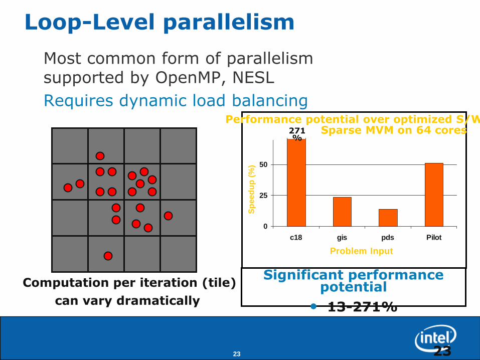
Loop-Level parallelism
Most common form of parallelismsupported by OpenMP, NESL
Requires dynamic load balancing
Significant performance potential
• 13-271%
0
25
50
c18 gis pds Pilot
Problem InputS
peed
up
(%
)
Performance potential over optimized S/WSparse MVM on 64 cores271
%
Computation per iteration (tile)
can vary dramatically

24
Task-Level Parallelism
Irregular structured parallelism
- Trees to complex dependency graphs
Significant performance potential
• 15-32% for Backward solve
• Up to 241% for Canny
0
10
20
30
ken mod pds watson world
Problem Input
Sp
eed
up
(%
)
Performance potential over optimized S/WBackward Solve on 64 cores

25
Typical Parallel Program
void task(node)
{
Do(node);
foreach child of node
Enqueue(task,child);
}
A
B C D E
F G H
Task dependence graph
A B C D E F G H
Sparse matrix
Non-zero
Example module: forward solve
Use task parallelism
Task = unit of work

26 26
Typical Parallel Run-Time Systemvoid task(node)
{
Do(node);
foreach child of node
Enqueue(task,child);
}
taskchild - -
T1 T2
Software data
structure
(Holds tasks)
Tn
Run-time system creates tuple to represent task
- GPUs, conventional S/W (e.g., TBB) do this today
taskchild - -
T2 Tn
Multiple implementation options

27
Need for Hardware Acceleration
Software “Enqueue” & “Dequeue” is slow- Serial access to head/tail
Additional overhead for smart ordering of tasks- Placement, Cache/data locality, process prioritization, etc.
Overheads increase with more threads
For “frequent” enqueue/dequeue
resource checking overhead is wasteful
hardware does a fine job w/scheduling
allow fall-back to software on hardware queue limit (overflow/underflow)
Accelerate data structure accesses & task ordering with H/W

28 28
uArch Support for Carbon
GTUC1
$1C2
C7
Cn$m
$5
Core
L1 $ LTU
Global Task Unit (GTU)
Task pool storage
Local Task Unit (LTU)
Prefetches and buffers tasks

29 29
Performance: Loop/Vector Parallelism
• Significant performance benefit over optimized S/W 88% better on average
• Similar performance to “Ideal” 3% worse on average
Loop

30 30
Performance: Task-Level Parallelism
• Significant performance benefit over optimized S/W 98% better on average
• Similar performance to “Ideal” 2.7% worse on average

31
Task Queuing in the Interconnect
• Arrangement of GTU and LTU suffices for apps studied
• But, long vectors running on MCA can be tricky
o requires dynamic resource discovery
o Vector length breaks Dynamic Warp Formation and Scheduling for Efficient GPU Control Flow, Fung et al (Micro „07)

32
Partitioning, Isolation and QoSin Interconnects

33
MLC
LP
IA
LP
IA
LP
IA
LP
IA
MLC
LP
IA
LP
IA
LP
IA
LP
IA
MLC
LP
IA
LP
IA
LP
IA
LP
IA
MLC
LP
IA
LP
IA
LP
IA
LP
IA
MLC
LP
IA
LP
IA
LP
IA
LP
IA
MLC
LP
IA
LP
IA
LP
IA
LP
IA
MLC
LP
IA
LP
IA
LP
IA
LP
IA
MLC
LP
IA
LP
IA
LP
IA
LP
IA
Data mining OLTP Networking
MLC
LP
IA
LP
IA
LP
IA
LP
IA
MLC
LP
IA
LP
IA
LP
IA
LP
IA
MLC
LP
IA
LP
IA
LP
IA
LP
IA
MLC
LP
IA
LP
IA
LP
IA
LP
IA
MLC
LP
IA
LP
IA
LP
IA
LP
IA
MLC
LP
IA
LP
IA
LP
IA
LP
IA
MLC
LP
IA
LP
IA
LP
IA
LP
IAMLC
LP
IA
LP
IA
LP
IA
LP
IA
Interconnect
Analytics
Virtualization and Partitioning of on-chip Resources
Virtualize: interconnect, cache, memory, I/O, etcPartition : Cores, private caches, dedicated interconnect
Focus:

34
Domain isolation for performance and security
Shared Channel Reservation
Application Isolation enforced by Interconnect
Allow “arbitrary” shaped domains
2
1
3

35
Isolation with Fault Tolerance
1
3
1
2 3
1
Good cores become un-usable
2Reconfigure Partitions
Enable Fault Discovery & Repartitioning

36
Route Flexibility
Motivation
- Performance isolation
- Fault-tolerance
- Topology independence
- Load-balancing and
- Improved network efficiency2 big cores, 12 small cores, 4 MCs
Challenge: low area/timing overhead
to achieve routing flexibility
Logic Based Distributed Routing in NoC, Flich & Duato, Computer Arch Letters, Jan 2008
37
012345
0 1 2 3 4 5
0
0.01
0.02
0.03
0.04
0.05
0.06
0.07
0.08
0.09
0.1
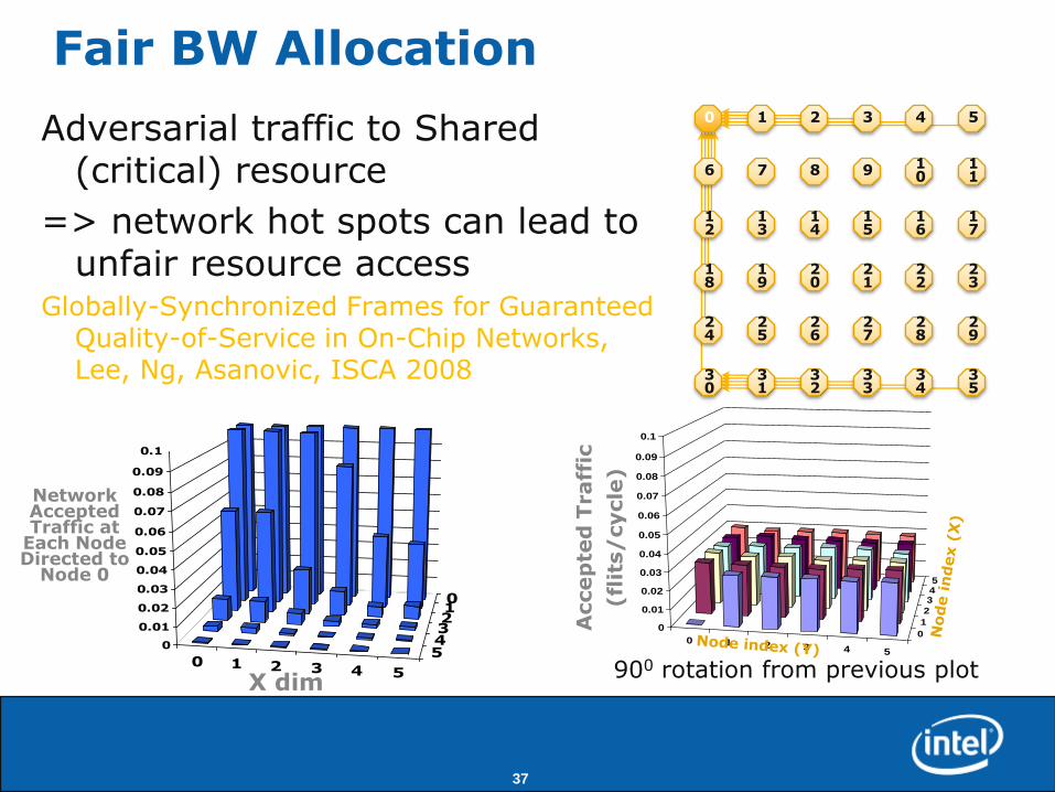
Fair BW Allocation
Adversarial traffic to Shared (critical) resource
=> network hot spots can lead to unfair resource access
Globally-Synchronized Frames for Guaranteed Quality-of-Service in On-Chip Networks, Lee, Ng, Asanovic, ISCA 2008
0 1 2 3 4 5
6 7 8 9 10
11
12
13
14
15
16
17
18
19
20
21
22
23
24
25
26
27
28
29
30
31
32
33
34
35
Network Accepted Traffic at
Each Node Directed to
Node 0
X dim
0 1 2 3 4 5
0
1
2
345
0
0.01
0.02
0.03
0.04
0.05
0.06
0.07
0.08
0.09
0.1
Accep
ted
Traff
ic
(fl
its/
cycle
)
900 rotation from previous plot

38
Technical Contributors
Mani Azimi, Akhilesh Kumar, Roy Saharoy, Aniruddha Vaidya, Sriram Vangal, Yatin Hoskote,
Sanjeev Kumar, Anthony Nguyen, Chris Hughes, Niket Agarwal,
and
the prototype design team
Ack support of: Mani Azimi, Nitin Borkar

39
Summary
• Energy efficient interconnects that scale are important for future multi-cores
• Interconnect can play a part in thread scheduling
• Application consolidation in many-core requires close cooperation with run-time.
• Efficient support required for route flexibility

40
Thanks!
Questions?