office of aviation safety usairways flight 1549 waterlanding … · 2018-01-26 · 1549, an airbus...
TRANSCRIPT

Office of Aviation Safety
USAirways Flight 1549
WaterLanding Hudson River
January 15, 2009

Details
• Airbus A320-214, N106US • January 15, 3:27 pm • LaGuardia to Charlotte • 150 passengers, 5 crew • 4 passengers and 1 flight attendant
seriously injured


Timing
• Rotation to birdstrikes = 1 min 37 sec • Birdstrikes to ditching = 3 min 31 sec • Total flight time = 5 min 8 sec • 1st rescue ferry arrival = 3 min 45 sec


Fan blade damage
LH Engine S/N 779-828

Fractured Booster IGVs
Fractured 1st stage booster blades

Damage to HP compressor


Docket No. SA-532 Exhibit No. 12
NATIONAL TRANSPORTATION SAFETY BOARD
WASHINGTON, D.C.
GROUP CHAIRMAN’S FACTUAL REPORT OF INVESTIGATION
COCKPIT VOICE RECORDER DCA09MA026
(47 Pages)

DCA09MA026 CVR Group Chairman’s Factual Report
Page 1 of 47
NATIONAL TRANSPORTATION SAFETY BOARD Vehicle Recorder Division Washington, D.C. 20594
GROUP CHAIRMAN’S FACTUAL REPORT OF INVESTIGATION Cockpit Voice Recorder
DCA09MA026
by
Douglass P. Brazy
Mechanical Engineer (CVR) Warning The reader of this report is cautioned that the transcription of a CVR tape is not a precise science but is the best product possible from an NTSB group investigative effort. The transcript, or parts thereof, if taken out of context, could be misleading. The attached CVR transcript should be viewed as an accident investigation tool to be used in conjunction with other evidence gathered during the investigation. Conclusions or interpretations should not be made using the transcript as the sole source of information.

DCA09MA026 CVR Group Chairman’s Factual Report
Page 2 of 47
NATIONAL TRANSPORTATION SAFETY BOARD Vehicle Recorder Division Washington, D.C. 20594
April 22, 2009
Cockpit Voice Recorder - 12
Group Chairman’s Factual Report
by Douglass P. Brazy
NTSB Accident Number DCA09MA026
A. ACCIDENT
Location: Weehawken, NJ Date: January 15, 2009 Time: 15:30 Eastern Standard Time Aircraft: Airbus Industrie A320-214, reg. N106US Operator: US Airways, Flight 1549
B. GROUP
Chairman: Douglass P. Brazy Mechanical Engineer (CVR) National Transportation Safety Board Member: Capt. Rudy Canto Director, Flight Operations Technical Airbus Member: Jeff Diercksmeier USAPA Accident Investigation Team US Airline Pilots Association Member: Capt. Chuck Pastene Check Airman Flight Training US Airways

DCA09MA026 CVR Group Chairman’s Factual Report
Page 3 of 47
Member: Floyd A. (Tony) James Air Safety Investigator, Office of Accident Investigation Federal Aviation Administration Member: Andy Mihalchik Program Mgr. Technical Pilot, Flight Operations Support GE Transportation – Aircraft Engines Member: Nicholas Marcou Deputy head, Investigations Department Bureau d’Enquetes et d’Analyses (BEA)
C. SUMMARY
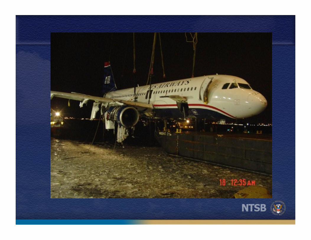
On January 15, 2009, about 1527 Eastern Standard Time, US Airways flight
1549, an Airbus A320-214, registration N106US, suffered bird ingestion into both
engines, lost engine thrust, and landed in the Hudson River following take off from New
York City's La Guardia Airport (LGA). The scheduled, domestic passenger flight,
operated under the provisions of Title 14 CFR Part 121, was en route to Charlotte
Douglas International Airport (CLT) in Charlotte, North Carolina. The 150 passengers
and 5 crewmembers evacuated the aircraft successfully. one flight attendant and four
passengers were seriously injured.
The Cockpit Voice Recorder (CVR) contained approximately thirty minutes and
twelve seconds of audio. The recording began at about 15:00:32 EST as the crew was
preparing for the flight, and ended at about 15:30:44 EST. A transcript of the entire
recording can be found in Attachment II.

DCA09MA026 CVR Group Chairman’s Factual Report
Page 4 of 47
D. DETAILS OF INVESTIGATION Recorder Examination, Disassembly, and Preparation
The NTSB Vehicle Recorder Division received an Allied Signal/Honeywell Solid
State Cockpit Voice Recorder, model SSCVR part number 980-6020-001, serial number
2878. The CVR was shipped immersed in fresh water.
Figure 1 - CVR as Received

DCA09MA026 CVR Group Chairman’s Factual Report
Page 5 of 47
Figure 2- Data plate
The CVR had no apparent external damage, other than being wet. The
underwater locator beacon (ULB Dukane Model DK100, s/n DM1661, battery expiration
date October, 2009) did not function when tested. After shorting the center electrode to
the case, no sound was detected using a Dukane Ultrasonic Test Set Model 42A12.
The beacon was also tested using a Dukane Test Set Model TS100, which indicated
“Open Probe/Batt.”
Figure 3 ULB and Test Set
DCA09MA026 CVR Group Chairman’s Factual Report
Page 6 of 47
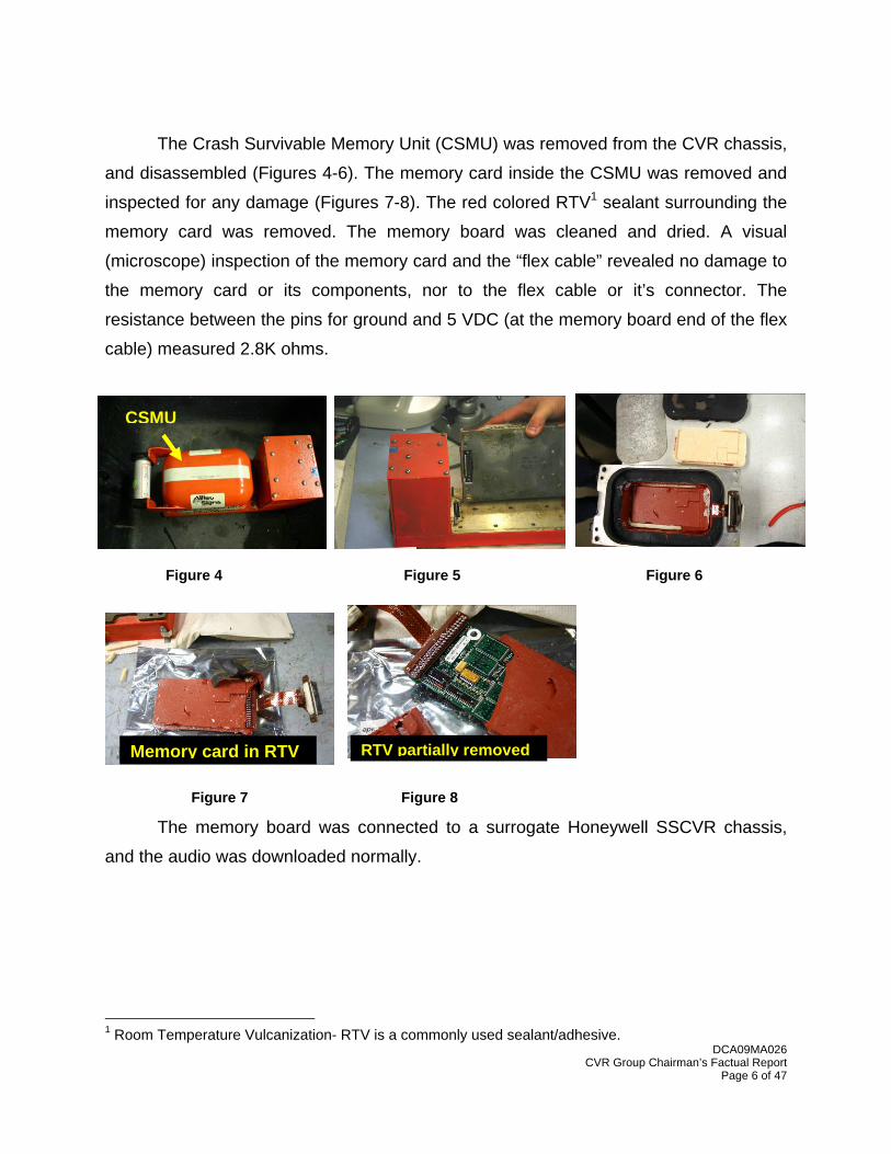
The Crash Survivable Memory Unit (CSMU) was removed from the CVR chassis,
and disassembled (Figures 4-6). The memory card inside the CSMU was removed and
inspected for any damage (Figures 7-8). The red colored RTV1 sealant surrounding the
memory card was removed. The memory board was cleaned and dried. A visual
(microscope) inspection of the memory card and the “flex cable” revealed no damage to
the memory card or its components, nor to the flex cable or it’s connector. The
resistance between the pins for ground and 5 VDC (at the memory board end of the flex
cable) measured 2.8K ohms.
The memory board was connected to a surrogate Honeywell SSCVR chassis,
and the audio was downloaded normally.
1 Room Temperature Vulcanization- RTV is a commonly used sealant/adhesive.
CSMU
Memory card in RTV RTV partially removed
Figure 4 Figure 5 Figure 6
Figure 7 Figure 8

DCA09MA026 CVR Group Chairman’s Factual Report
Page 7 of 47
CVR Channels
The recording consisted of four separate channels of audio information. One
channel contained the cockpit area microphone (CAM) audio information. The CAM is
typically mounted in the overhead panel between the two pilots. It is designed to
capture sounds and conversations in the cockpit area whenever the CVR system is
powered.
Two of the channels contained audio information from the Captain’s and First
Officer’s audio panels, respectively. The audio panels are essentially an interface
between the pilot’s headsets and the airplane’s communication equipment. Radio
transmissions (both transmitted and received), are captured on these channels.
Additionally, “hot” microphone signals (when used) are captured through the audio
panels on these channels. Hot microphones are the same microphones in the pilot’s
headsets that can be used for making radio transmissions. The “hot” means that they
are always on and being recorded by the CVR, whether or not a radio transmission is
being made. On this recording, it appears that hot microphones were used by both
pilots. The fourth channel contained audio information from the aircraft’s Public Address
(PA) system.
Recording Quality2
The recording quality was rated as Good to Excellent. At times, the pilot’s voices
were difficult to hear on their respective CVR channels, due to simultaneous VHF radio
communications being monitored and recorded on the same CVR channel as each
pilot’s HOT microphone.
2 See Attachment I for a CVR Quality Ranking Scale.

DCA09MA026 CVR Group Chairman’s Factual Report
Page 8 of 47
Group Activities
The CVR group convened January 22, 2009. The group reviewed the recording
and prepared a transcript of the entire recording. Each channel was reviewed
individually as well as in combination with the other channels. There was little difficulty
identifying the sources of each comment, and the group agreed on the content of each
comment and characterization of each sound in the attached transcript.
Flight Crew Review of Recording and Transcript
On May 8, 2009 the Captain and First Officer, along with the USAPA CVR
Groupmemember, reviewed the recording and the attached transcript for accuracy. The
crew made the following clarification:
In reference to the transcription at time 15:30:38, the transcribed phrase
“* * switch?”
The crew indicated that the First Officer was referring to a cabin emergency
notification switch, which provides a signal to the cabin crew indicating an
emergency.
The crew also made the following editorial comments:
At 15:19:03, the transcription of “check.” should be: “checked.” At 15:20:42, the transcription of “on the hold.” should be: “on to hold.”
At 15:24:56.7, the transcription of “Cactus fifteen forty nine clear for takeoff.”
should be: “Cactus fifteen forty nine cleared for takeoff.”
At 16:26:37, the transcription of “uh what a view of the Hudson today.” should be:
“and what a view of the Hudson today.”

DCA09MA026 CVR Group Chairman’s Factual Report
Page 9 of 47
At 15:27:32.9, the transcription of “mayday mayday mayday. uh this is uh Cactus
fifteen thirty nine hit birds, we've lost thrust (in/on) both engines we're turning
back towards LaGuardia.” should be: “mayday mayday mayday. uh this is uh
Cactus fifteen thirty nine hit birds, we've lost thrust in both engines we're turning
back towards LaGuardia”.
At 15:28:19, the transcription of “(it’s/is) online.” should be: “it’s online.”
At 15:30:41.1 the transcription of “(fifty or thirty)” should be: “fifty”3
Timing and Correlation
The times reported in the attached CVR transcript are Eastern Standard Time
(EST)4, and represent the time that each comment or sound begins5. Time is specified
to the nearest whole second, unless otherwise noted.
The CVR and FDR data were synchronized to one another by comparing the
FDR “Key VHF” parameter with radio transmissions as heard on the CVR recording. By
comparing the CVR elapsed time (time since the beginning of the CVR recording) for
radio transmissions to the corresponding FDR Subframe Reference Number (SRN) for
“Key VHF”, a relationship between the CVR elapsed time and the FDR SRN time can be
developed.
Generally, a single keying event can be used to synchronize the CVR to the FDR
to within +/- 1 second, due to the FDR’s 1 Hz sample rate for “Key VHF”. Using multiple
keying events may increase the accuracy of the synchronization. In this case, the start
and end times for six radio transmissions (12 keying events) were evaluated. Based on
3 It was difficult for the CVR group to differentiate this callout as being either “fifty” or “thirty”. According to the Flight Data Recorder, the last recorded radio altitude (Radio Altitude 2) prior to this callout, was 33 feet at time 15:30:40.26. The next recorded radio altitude (Radio Altitude 1) was 20 feet, at time 15:30:41.26. 4 Based on the clock used by the FAA’s Airport Surveillance Radar at Newark. 5 Except for outgoing radio transmissions. The time associated with these typically reflects the “key up” of the microphone or “click” that can often be heard before (and after) a radio transmission is made.

DCA09MA026 CVR Group Chairman’s Factual Report
Page 10 of 47
these 12 events, the resulting equation provided below is accurate within +/- 0.1 (one
tenth) of a second.
CVR Elapsed Time + 63732.8 = FDR SRN [Eqn. 1]
The time correlation from FDR SRN to Eastern Standard Time was provided by
the Aircraft Performance Specialist:
Eastern Standard Time = FDR SRN – 9701.119 [Eqn. 2]
(where Eastern Standard Time is expressed as seconds after midnight)
For more information, see the Aircraft Performance Study and the Flight Data
Recorder Group Chairman’s Factual reports for this investigation.
Douglass P. Brazy Mechanical Engineer (CVR)

DCA09MA026 CVR Group Chairman’s Factual Report
Page 11 of 47
Attachment I CVR Quality Rating Scale
The levels of recording quality are characterized by the following traits of the cockpit voice recorder information: Excellent Quality Virtually all of the crew conversations could be accurately and
easily understood. The transcript that was developed may indicate only one or two words that were not intelligible. Any loss in the transcript is usually attributed to simultaneous cockpit/radio transmissions that obscure each other.
Good Quality Most of the crew conversations could be accurately and easily
understood. The transcript that was developed may indicate several words or phrases that were not intelligible. Any loss in the transcript can be attributed to minor technical deficiencies or momentary dropouts in the recording system or to a large number of simultaneous cockpit/radio transmissions that obscure each other.
Fair Quality The majority of the crew conversations were intelligible. The
transcript that was developed may indicate passages where conversations were unintelligible or fragmented. This type of recording is usually caused by cockpit noise that obscures portions of the voice signals or by a minor electrical or mechanical failure of the CVR system that distorts or obscures the audio information.
Poor Quality Extraordinary means had to be used to make some of the crew
conversations intelligible. The transcript that was developed may indicate fragmented phrases and conversations and may indicate extensive passages where conversations were missing or unintelligible. This type of recording is usually caused by a combination of a high cockpit noise level with a low voice signal (poor signal-to-noise ratio) or by a mechanical or electrical failure of the CVR system that severely distorts or obscures the audio information.
Unusable Crew conversations may be discerned, but neither ordinary nor
extraordinary means made it possible to develop a meaningful transcript of the conversations. This type of recording is usually caused by an almost total mechanical or electrical failure of the CVR system.

DCA09MA026 CVR Group Chairman’s Factual Report
Page 12 of 47
Attachment II – Transcript
Transcript of an Allied Signal/Honeywell model SSCVR cockpit voice recorder (CVR), s/n 2878, installed on an Airbus Industrie A320-214, registration N106US. The airplane was operated by US Airways as Flight 1549, when it ditched into the Hudson River, NY, on January 15, 2009.
LEGEND ATIS Radio transmission from the Automated Terminal Information
System RDO Radio transmission from accident aircraft, US Airways 1549
CAM Cockpit area microphone voice or sound source
PA Voice or sound heard on the public address system channel HOT Hot microphone voice or sound source1 INTR Interphone communication to or from ground crew
For RDO, CAM, PA, HOT and INTR comments: -1 Voice identified as the Captain -2 Voice identified as the First Officer -3 Voice identified as cabin crewmember -4 Voice identified as groundcrew -? Voice unidentified
FWC Automated callout or sound from the Flight Warning Computer TCAS Automated callout or sound from the Traffic Collision Avoidance
System PWS Automated callout or sound from the Predictive Windshear System GPWS Automated callout or sound from the Ground Proximity Warning
System EGPWS Automated callout or sound from the Enhanced Ground Proximity
Warning system RMP Radio transmission from ramp control at LaGuardia
1 This recording contained audio from Hot microphones used by the flightcrew. The voices or sounds on these channels were also, at times, heard by the CVR group on the CAM channel and vice versa. In these cases, comments are generally annotated as coming from the source (either HOT or CAM) from which the comment was easiest to hear and discern.

DCA09MA026 CVR Group Chairman’s Factual Report
Page 13 of 47
GND Radio transmission from ground control at LaGuardia CLC Radio transmission from clearance delivery at LaGuardia
TWR Radio transmission from the Air Traffic Control Tower at LaGuardia DEP Radio transmission from LaGuardia departure control 4718 Radio transmission from another airplane (Eagle flight 4718)
CH[1234] CVR Channel identifier 1=Captain 2= First Officer 3= PA 4= Cockpit Area Microphone * Unintelligible word
@ Non-Pertinent word & Third party personal name (see note 5 below)
# Expletive
-, - - - Break in continuity or interruption in comment
( ) Questionable insertion
[ ] Editorial insertion
... Pause
Note 1: Times are expressed in Eastern Standard Time (EST), based on the clock used to timestamp the
recorded radar data from the Newark ASR-9. Note 2: Generally, only radio transmissions to and from the accident aircraft were transcribed. Note 3: Words shown with excess vowels, letters, or drawn out syllables are a phonetic representation of the words
as spoken. Note 4: A non-pertinent word, where noted, refers to a word not directly related to the operation, control or condition
of the aircraft. Note 5: Personal names of 3rd parties not involved in the conversation are generally not transcribed.

INTRA-COCKPIT COMMUNICATION AIR-GROUND COMMUNICATION TIME and TIME and SOURCE CONTENT SOURCE CONTENT
DCA09MA026 CVR Group Chairman’s Factual Report
Page 14 of 47
15:00:32 [Start of Recording] 15:00:32 [Start of Transcript]
15:00:32 ATIS
expressway visual runway three one approach in use. depart runway four, bravo four hold line in use. LaGuardia class bravo services avail-able on frequency one two six point zero five. all pilots read back all hold short instructions and assigned altitudes. advise on initial contact you have information papa... LaGuardia airport in-formation papa. one nine five one zulu. winds three four zero at one three, visibility one zero. ceiling three thousand five hundred broken. temperature minus six dewpoint minus one four. altimeter three zero two three. remarks A O two sea level pressure two three four. [ATIS repeats on ch2 until time 15:02:44.]
15:02:19 CAM-1
yes, thank you.
15:02:21 CAM-1
so we should have two open seats (cause) the jumpseaters are gonna sit in the back.
15:02:25 CAM-?
thank you.
15:02:26 CAM-1
all right anytime.

INTRA-COCKPIT COMMUNICATION AIR-GROUND COMMUNICATION TIME and TIME and SOURCE CONTENT SOURCE CONTENT
DCA09MA026 CVR Group Chairman’s Factual Report
Page 15 of 47
15:02:27 CAM-?
cool you bet.
15:02:30 CAM-?
ok.
15:02:35 HOT-2
the seats uh-
15:02:37 HOT-1
there you go.
15:02:45 CAM-?
do you mind if I keep my bag(s) up here?
15:02:47 CAM-1
no not at all.
15:02:48 CAM-?
thank you so much.
15:02:51 PA-1
a quick hello from the cockpit crew, this is fifteen forty nine bound for Charlotte. its a nice day for flying, be at thirty eight thousand feet mostly smooth about an hour and forty five minutes takeoff to landing, welcome aboard.
15:03:12 CAM-2
quite a difference in the flight time pretty in-credible, huh? fifty six minutes.
15:03:15 HOT-1
well we had a hundred and sixty knots of wind all the way up here. its a average headwind on this lists minus one ten.

INTRA-COCKPIT COMMUNICATION AIR-GROUND COMMUNICATION TIME and TIME and SOURCE CONTENT SOURCE CONTENT
DCA09MA026 CVR Group Chairman’s Factual Report
Page 16 of 47
15:03:34 HOT-1
all right.
15:03:34 PA-3
if everyone would please take their seats.
15:03:39 HOT-1
* *.
15:03:40 INTR-4
hello cockpit ground's ready.
15:03:42 INTR-1
we'll give them a call.
15:03:42 RDO-2
(ground) fifteen forty nine like to push at uh gate twenty one.
15:03:47 RMP
Cactus (fifteen) forty nine....gate twenty one, spot twenty eight, ground * for your taxi.
15:03:55 RDO-2
ok uh. that's uh * what's wrong here. [may be multiple mic keys]
15:03:57 HOT-1
ok... clear to push?
15:04:00 HOT-2
yeah.
15:04:01 INTR-4
yes sir, you say you are clear to push?

INTRA-COCKPIT COMMUNICATION AIR-GROUND COMMUNICATION TIME and TIME and SOURCE CONTENT SOURCE CONTENT
DCA09MA026 CVR Group Chairman’s Factual Report
Page 17 of 47
15:04:02 INTR-1
clear to push, spot twenty eight, brakes re-leased.
15:04:03 RDO-2
and that's uh spot twenty eight for Cactus uh nine- er fifteen forty nine, excuse me and over to ground twenty one seven.
15:04:05 INTR-4
twenty eight, brakes released.
15:04:09 RMP
affirmative.
15:04:09 CAM-?
seated and stowed.
15:04:11 HOT-1
thank you, all set.
15:04:13 CAM
[sound similar to cockpit door closing]
15:04:20 HOT-1
ok. that # door again.
15:04:23 HOT-2
what's wrong?
15:04:24 HOT-1
this-
15:04:25 HOT-2
oh.
15:04:25 CAM-1
(you) have to slam it pretty hard.

INTRA-COCKPIT COMMUNICATION AIR-GROUND COMMUNICATION TIME and TIME and SOURCE CONTENT SOURCE CONTENT
DCA09MA026 CVR Group Chairman’s Factual Report
Page 18 of 47
15:04:29 CAM
[sound similar to cockpit door closing]
15:04:52 HOT-1
got the newest Charlotte.
15:05:04 PA-3
ladies and gentlemen all electronic devices have to be turned off at this time, anything with an on off button must be in the off position.
15:05:07 HOT-1
yeah too bad they aren't still using three one... for takeoff.
15:05:10 HOT-2
yeah.
15:05:11 HOT-1
I was hoping we could land on four and takeoff on three one, but it didn't quite work out that way.
15:05:22 HOT-2
well we can make an attempt to beat Northwest here anyways.
15:05:25 HOT-1
what's that?
15:05:26 HOT-2
so we can make an attempt to beat Northwest but he's already starting isn't he.
15:05:29 HOT-1
yeah. and we have to pull up before we can even start on this.
INTRA-COCKPIT COMMUNICATION AIR-GROUND COMMUNICATION TIME and TIME and SOURCE CONTENT SOURCE CONTENT
DCA09MA026 CVR Group Chairman’s Factual Report
Page 19 of 47
15:05:32 HOT-2
they start their number two engine first.
15:05:34 PA-3
good afternoon ladies and gentlemen welcome on board US Airways flight fifteen forty nine, with service to Charlotte. please take a moment to listen to this important safety information, in preparation for departure be certain that your seat back is straight up and your tray table is stowed. all carryon items must be secured com-pletely underneath the seat in front of you, or stowed in an overhead compartment. please use caution when placing items in or removing them from the overhead bins. please ensure that all electronic devices are turned off, some devices such as cell phones, TVs, radios and any device transmitting a signal may not be used at anytime during flight. however you may be certain * * use other electronic devices when advised by your crew. please direct your atten-tion to the flight attendants in the cabin, for eve-ryone's safety regulations require your compli-ance with all lighted signs, placards, and crew-member instructions. whenever the seatbelt sign is illuminated please make sure that you seat-belt is fastened low and tight around your hips. to fasten insert the metal fitting into the buckle and tighten by pulling loose end away from you. to release lift the metal flap. during the flight the
INTRA-COCKPIT COMMUNICATION AIR-GROUND COMMUNICATION TIME and TIME and SOURCE CONTENT SOURCE CONTENT
DCA09MA026 CVR Group Chairman’s Factual Report
Page 20 of 47
Captain may turn off the fasten seatbelt sign, however for safety we recommend that you keep your seatbelt fastened at all times. please review the safety instruction card in the seat-back pocket in front of you, it explains the safety features of this aircraft as well as the location and operation of the exit and flotation devices. your seat cushion serves as a flotation device, to remove your cushion, (pla)- take it with you to the nearest usable exit, when exiting the-[sound similar to power interruption 15:07:01] place both arms through the straps and hug it to your chest. flight attendants are pointing out there are a total of eight exits on this aircraft, two door ex-its in front of the aircraft, four window exits over the wings, and two door exits in the rear of the aircraft. once again, two door exits at the front of the aircraft, four window exits over the wings, and two door exits in the rear of the aircraft. each door is equipped with an evacuation slide if directed to exit... the aircraft jump onto the slide and move away from the aircraft. take a moment to locate the exit nearest you keeping in mind that the closest usable exit may be lo-cated behind you. if there is a loss of electrical power low level lighting will guide you to the ex-its indicated by illuminated exit signs. if needed oxygen masks will be released from the over-head, to start the flow of oxygen, reach up and pull the mask toward you, fully extending the
INTRA-COCKPIT COMMUNICATION AIR-GROUND COMMUNICATION TIME and TIME and SOURCE CONTENT SOURCE CONTENT
DCA09MA026 CVR Group Chairman’s Factual Report
Page 21 of 47
plastic tubing. place the mask over your nose and mouth, place the elastic band over your head. to tighten pull the tab on each side of the mask. the plastic bag does not inflate when oxy-gen is flowing. secure your mask before assist-ing others. as a reminder smoking is prohibited in all areas of the aircraft including the lavato-ries. federal regulations prohibit tampering with disabling or destroying a lavatory smoke detec-tor. on behalf of your entire crew, its our pleas-ure to have you on board.... thank you for flying US Airways.
15:05:34 HOT-1
that's interesting.
15:05:41 HOT-2
did you always start number one or is that a uh America West thing?
15:05:44 HOT-1
no that's no its been that way ever since I've been on it, for six and a half years anyway.
15:06:09 INTR-1
confirm we're clear to start?
15:06:10 INTR-4
uh, one second.
15:06:13 HOT-1
he told me to wait.
15:06:15 HOT-2
he did?

INTRA-COCKPIT COMMUNICATION AIR-GROUND COMMUNICATION TIME and TIME and SOURCE CONTENT SOURCE CONTENT
DCA09MA026 CVR Group Chairman’s Factual Report
Page 22 of 47
15:06:16 HOT-1
yeah, this guy was giving the signal but I asked and he said no wait just a second.
15:06:17 HOT-2
yeah.... OK.
15:06:25 INTR-4
kay. clear to start.
15:06:26 INTR-1
clear to start.
15:06:26 HOT-1
start engines.
15:06:44 HOT-2
wonder how the Northwest and Delta pilots are gettin on.
15:06:47 HOT-1
I wonder about that too, I have no idea.
15:07:01 CAM
[sound similar to power interruption]
15:07:01 CAM
[sound similar to increase in engine noise/frequency]
15:07:04 HOT-1
yeah hopefully better than we and West do.
15:07:11 HOT-2
be hard to do worse.
INTRA-COCKPIT COMMUNICATION AIR-GROUND COMMUNICATION TIME and TIME and SOURCE CONTENT SOURCE CONTENT
DCA09MA026 CVR Group Chairman’s Factual Report
Page 23 of 47
15:07:13 HOT-1
yeah... well I hadn't heard much about it lately but I can't imagine it'd be any better.
15:07:20 HOT-2
I think that's just cause we're separate..... and there's nothing going on right now.
15:07:25 HOT-1
right.
15:07:28 INTR-4
kay set the parking brake.
15:07:32 INTR-1
parking brake set. disconnect.
15:07:34 INTR-4
brake set, disconnect.
15:08:15 HOT-1
okay wands up, wave off.
15:08:16 HOT-2
wands up.
15:08:17 HOT-1
flaps two, taxi.
15:08:36 RDO-2
ground Cactus uh fifteen forty nine spot twenty eight, taxi please.
15:08:40 GND
Cactus fifteen forty nine LaGuardia ground run-way four uh, turn left alpha, short of golf, and uh did you call clearance?

INTRA-COCKPIT COMMUNICATION AIR-GROUND COMMUNICATION TIME and TIME and SOURCE CONTENT SOURCE CONTENT
DCA09MA026 CVR Group Chairman’s Factual Report
Page 24 of 47
15:08:48 RDO-2
(I'm) sorry forgot.
15:08:48 HOT-1
*.
15:08:52 HOT-1
uh thirty five two. so its alpha short of golf is that right?
15:08:56 HOT-2
yup.
15:08:57 HOT-1
yeah I'll start taxiing while you do that.
15:08:58 HOT-2
ok.
15:09:35 RDO-2
Cactus fifteen forty nine is uh over BIGGY seven one three four, and three sixty and up to five thousand.
15:09:44 HOT-1
you put it here.
15:09:46 HOT-2
what was that?... am I on the wrong one?
15:09:53 HOT-1
you switched me off of ground.
15:09:55 HOT-2
oh, sorry.
15:09:57 HOT-?
* you wanna be there [heard on CH2]

INTRA-COCKPIT COMMUNICATION AIR-GROUND COMMUNICATION TIME and TIME and SOURCE CONTENT SOURCE CONTENT
DCA09MA026 CVR Group Chairman’s Factual Report
Page 25 of 47
15:10:04 HOT-1
you were talking on number two but you switched number one.
15:10:07 HOT-2
ok.
15:10:11 RDO-2
I'm sorry I messed up my radio here Cactus fif-teen forty nine, seven one three four and we're three sixty up to five thousand.
15:10:40 RDO-2
Cactus-
15:10:41 RDO-2
Cactus fifteen forty nine is uh squawking seven one three four and were uh runway four three sixty and five thousand.
15:10:48 CLC
(kay it's) fifteen forty nine LaGuardia clearance read *back correct, ground point seven verify information papa.
15:10:53 RDO-2
we have papa.
15:10:54 RDO-2
we have papa thank you Cactus uh * fifteen forty nine.
15:10:58 CLC
ground point seven.
15:11:05 HOT-2
ok.

INTRA-COCKPIT COMMUNICATION AIR-GROUND COMMUNICATION TIME and TIME and SOURCE CONTENT SOURCE CONTENT
DCA09MA026 CVR Group Chairman’s Factual Report
Page 26 of 47
15:11:06 HOT-1
ok no change.
15:11:08 HOT-2
I don't think my uh MIC switch works all the time here.
15:11:12 HOT-1
your trigger, your trigger?
15:11:12 CAM-2
* * transmit.
15:11:14 CAM-2
what's that?
15:11:15 HOT-1
your trigger on the stick? ... I'll write that up too.
15:11:18 CAM-2
so you don't hear me transmit... you might wanna jump in.
15:11:21 HOT-1
ok.... got it.
15:11:25 RDO-1
and OPS, fifteen forty nine.
15:11:28 HOT-1
I'm calling on number two.
15:11:31 OPS
yeah, (sixteen) forty nine go ahead.

INTRA-COCKPIT COMMUNICATION AIR-GROUND COMMUNICATION TIME and TIME and SOURCE CONTENT SOURCE CONTENT
DCA09MA026 CVR Group Chairman’s Factual Report
Page 27 of 47
15:11:33 RDO-1
yeah fifteen forty nine if you want uh weight and balance uh corrected to total of passenger one forty eight and ACM [additional crew members] two.
15:11:42 OPS
ok one forty eight.
15:11:51 RDO-1
yeah for fifteen forty nine passenger count is one four eight, plus ACM two.
15:12:00 RDO-1
so one forty eight, plus two ACM's.
15:12:02 OPS
ok. copy that.
15:12:08 HOT-1
all right... I'm still holding short of golf, and they're correcting the passenger count to one forty eight.
15:12:25 GND
Cactus fifteen forty nine taxi foxtrot, bravo hold short echo, just gotta hold you there for about three minutes uh for your uh in trail into Char-lotte.
15:12:31 RDO-2
foxtrot, bravo, short of echo, Cactus fifteen forty nine.

INTRA-COCKPIT COMMUNICATION AIR-GROUND COMMUNICATION TIME and TIME and SOURCE CONTENT SOURCE CONTENT
DCA09MA026 CVR Group Chairman’s Factual Report
Page 28 of 47
15:12:35 HOT-1
ok, foxtrot, bravo, hold short of echo... and once we stop then, I'll do the flight control check.
15:12:57 HOT-1
did it uh, did it not uplink?
15:13:01 HOT-2
(well) I figured it was the old one.
15:13:04 HOT-1
what's that?
15:13:06 HOT-2
umm.... ok.
15:13:18 HOT-2
so do you want me to use this one?
15:13:19 HOT-1
oh... oh I see what you're saying, yeah I uh you can wait if you want I just thought we'd have something in there.
15:13:37 HOT-1
yeah we can wait, that's fine.
15:13:38 HOT-2
go with this one? ok.
15:13:40 HOT-1
cause we're going to be holding here for a min-ute anyway.... all right foxtrot, bravo, hold short of echo.

INTRA-COCKPIT COMMUNICATION AIR-GROUND COMMUNICATION TIME and TIME and SOURCE CONTENT SOURCE CONTENT
DCA09MA026 CVR Group Chairman’s Factual Report
Page 29 of 47
15:14:15 HOT-1
where is the uh, the portion of the release the- of the weight and balance part of it that was be-low what you tore off to put on here... or was there part of it.
15:14:24 HOT-2
there was, I think I threw it away it just had names on it... its right here.
15:14:26 HOT-1
ok thank you. I need this number, yeah I wanted this part... I'm gonna just call this guy directly cause I don't think this OPS guy knows what the # he's doin.
15:15:04 HOT-1
I'm just gonna call our load control agent di-rectly, it's his number right here.
15:15:12 FWC
[sound of single chime]
15:15:15 HOT-1
yeah I'm the Captain on fifteen forty nine aircraft one zero six if you'll if you will please correct the passenger count we have a total of one four eight, plus two plus two ACM. [sounds as if this communication is by cellular telephone]
15:15:19 GND
Cactus fifteen forty nine follow the Northwest you can monitor tower.
INTRA-COCKPIT COMMUNICATION AIR-GROUND COMMUNICATION TIME and TIME and SOURCE CONTENT SOURCE CONTENT
DCA09MA026 CVR Group Chairman’s Factual Report
Page 30 of 47
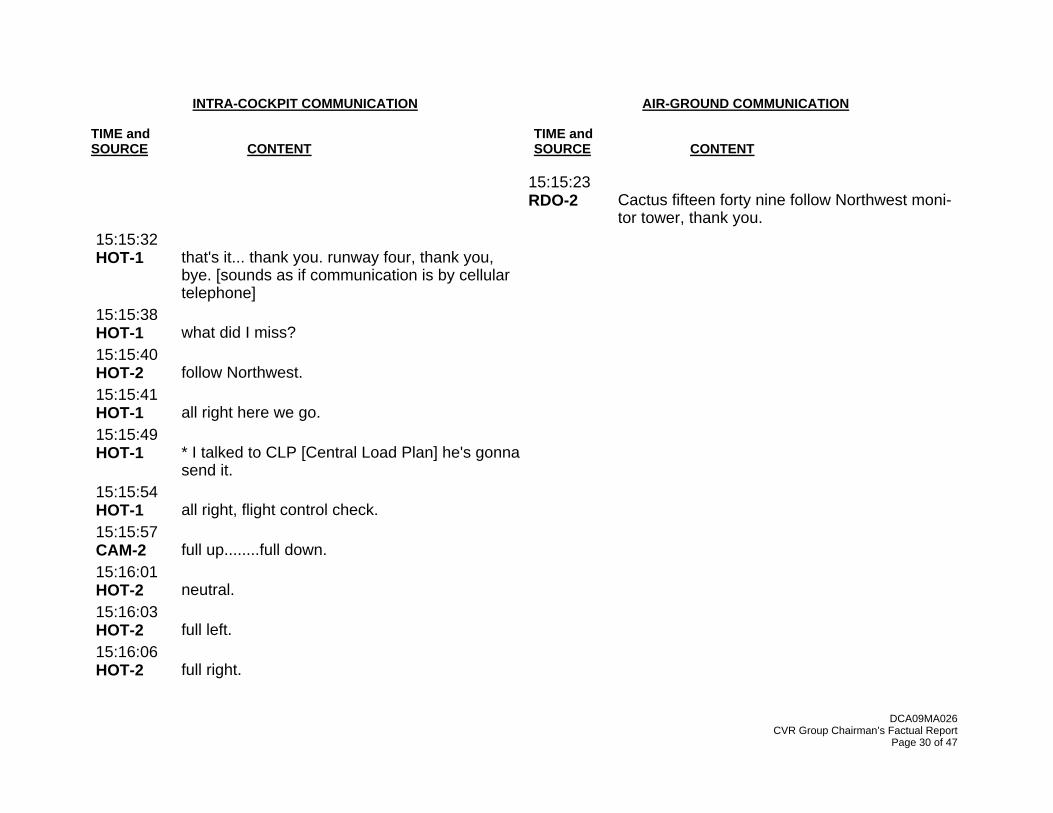
15:15:23 RDO-2
Cactus fifteen forty nine follow Northwest moni-tor tower, thank you.
15:15:32 HOT-1
that's it... thank you. runway four, thank you, bye. [sounds as if communication is by cellular telephone]
15:15:38 HOT-1
what did I miss?
15:15:40 HOT-2
follow Northwest.
15:15:41 HOT-1
all right here we go.
15:15:49 HOT-1
* I talked to CLP [Central Load Plan] he's gonna send it.
15:15:54 HOT-1
all right, flight control check.
15:15:57 CAM-2
full up........full down.
15:16:01 HOT-2
neutral.
15:16:03 HOT-2
full left.
15:16:06 HOT-2
full right.

INTRA-COCKPIT COMMUNICATION AIR-GROUND COMMUNICATION TIME and TIME and SOURCE CONTENT SOURCE CONTENT
DCA09MA026 CVR Group Chairman’s Factual Report
Page 31 of 47
15:16:07 HOT-2
neutral.
15:16:09 HOT-2
full left.
15:16:11 HOT-2
full right.
15:16:13 HOT-2
neutral.
15:17:26 HOT-1
I'll go ahead and sit them down.
15:17:30 PA-1
flight attendants please be seated for takeoff.
15:17:33 HOT-2
kay.
15:18:03 HOT-1
okay, taxi check.
15:18:07 HOT-2
* *.
15:18:19 HOT-2
departure briefing, FMS. [Flight Management System]
15:18:21 HOT-1
reviewed runway four.
15:18:22 HOT-2
flaps verify. two planned, two indicated.
15:18:24 HOT-1
two planned, two indicated.

INTRA-COCKPIT COMMUNICATION AIR-GROUND COMMUNICATION TIME and TIME and SOURCE CONTENT SOURCE CONTENT
DCA09MA026 CVR Group Chairman’s Factual Report
Page 32 of 47
15:18:46 HOT-2
um. takeoff data verify... one forty, one forty five, one forty nine, TOGA. [Takeoff/Go Around]
15:18:53 HOT-1
one forty, one forty five, one forty nine, TOGA.
15:18:56 HOT-2
the uh weight verify, one fifty two point two.
15:19:00 HOT-1
one fifty two point two.
15:19:02 HOT-2
flight controls verify checked.
15:19:03 HOT-1
check.
15:19:04 HOT-2
stab and trim verify, thirty one point one per-cent... and zero.
15:19:08 HOT-1
thirty one point one percent, zero.
15:19:11 HOT-2
the uh.... engine anti-ice.
15:19:13 HOT-1
is off.
15:19:16 CAM-2
ECAM [Electronic Centralized Aircraft Monitor-ing] verify takeoff, no blue, status checked.
15:19:19 HOT-1
takeoff, no blue, status checked.

INTRA-COCKPIT COMMUNICATION AIR-GROUND COMMUNICATION TIME and TIME and SOURCE CONTENT SOURCE CONTENT
DCA09MA026 CVR Group Chairman’s Factual Report
Page 33 of 47
15:19:22 PA-2
ladies and gentlemen at this time we're number one for takeoff, flight attendants please be seated.
15:19:25 HOT-1
* *.
15:19:27 HOT-2
takeoff min fuel quantity verify. nineteen thou-sand pounds required we got twenty one point eight on board.
15:19:32 HOT-1
nineteen thousand pounds required, twenty one eight on board.
15:19:35 HOT-2
flight attendants notified, engine mode is nor-mal, the taxi checklist is complete sir.
15:19:40 HOT-1
below the line... oh you finished it all * * -
15:19:42 CAM-2
yeah.
15:19:42 HOT-1
-yeah kay thank you. we're good. holding short.
15:20:03 HOT-1
still possible.
15:20:06 CAM-2
oh yeah.

INTRA-COCKPIT COMMUNICATION AIR-GROUND COMMUNICATION TIME and TIME and SOURCE CONTENT SOURCE CONTENT
DCA09MA026 CVR Group Chairman’s Factual Report
Page 34 of 47
15:20:37 TWR
Cactus fifteen forty nine, LaGuardia runway four position and hold. traffic to land three one.
15:20:40 RDO-2
position and hold runway four, Cactus uh fifteen forty nine.
15:20:42 HOT-1
on the hold.
15:20:44 CAM
[sound similar to increase then decrease in en-gine noise/frequency]
15:21:27 HOT-1
your brakes, your aircraft.
15:21:30 HOT-2
my aircraft.
15:21:48 HOT-1
he's gotta *.
15:24:54 TWR
Cactus fifteen forty nine runway four clear for takeoff.
15:24:56.7 RDO-1
Cactus fifteen forty nine clear for takeoff.
15:25:06 CAM
[sound similar to increase in engine noise/speed]
15:25:09 CAM-2
TOGA.

INTRA-COCKPIT COMMUNICATION AIR-GROUND COMMUNICATION TIME and TIME and SOURCE CONTENT SOURCE CONTENT
DCA09MA026 CVR Group Chairman’s Factual Report
Page 35 of 47
15:25:10 HOT-1
TOGA set.
15:25:20 HOT-1
eighty.
15:25:21 HOT-2
checked.
15:25:33 HOT-1
V one, rotate.
15:25:38 HOT-1
positive rate.
15:25:39 HOT-2
gear up please.
15:25:39 HOT-1
gear up.
15:25:45 TWR
Cactus fifteen forty nine contact New York de-parture, good day.
15:25:48 RDO-1
good day.
15:25:49 HOT-2
heading select please.
15:25:51.2 RDO-1
Cactus fifteen forty nine, seven hundred, climb-ing five thousand.

INTRA-COCKPIT COMMUNICATION AIR-GROUND COMMUNICATION TIME and TIME and SOURCE CONTENT SOURCE CONTENT
DCA09MA026 CVR Group Chairman’s Factual Report
Page 36 of 47
15:26:00 DEP
Cactus fifteen forty nine New York departure radar contact, climb and maintain one five thou-sand.
15:26:02 CAM
[sound similar to decrease in engine noise/speed]
15:26:03.9 RDO-1
maintain one five thousand Cactus fifteen forty nine.
15:26:07 HOT-1
fifteen.
15:26:08 HOT-2
fifteen. climb.
15:26:10 HOT-1
climb set.
15:26:16 HOT-2
and flaps one please.
15:26:17 HOT-1
flaps one.
15:26:37 HOT-1
uh what a view of the Hudson today.
15:26:42 HOT-2
yeah.
15:26:52 HOT-2
flaps up please, after takeoff checklist.

INTRA-COCKPIT COMMUNICATION AIR-GROUND COMMUNICATION TIME and TIME and SOURCE CONTENT SOURCE CONTENT
DCA09MA026 CVR Group Chairman’s Factual Report
Page 37 of 47
15:26:54 HOT-1
flaps up.
15:27:07 HOT-1
after takeoff checklist complete.
15:27:10.4 HOT-1
birds.
15:27:11 HOT-2
whoa.
15:27:11.4 CAM
[sound of thump/thud(s) followed by shuddering sound]
15:27:12 HOT-2
oh #.
15:27:13 HOT-1
oh yeah.
15:27:13 CAM
[sound similar to decrease in engine noise/frequency begins]
15:27:14 HOT-2
uh oh.
15:27:15 HOT-1
we got one rol- both of 'em rolling back.
15:27:18 CAM
[rumbling sound begins and continues until ap-proximately 15:28:08]
15:27:18.5 HOT-1
ignition, start.

INTRA-COCKPIT COMMUNICATION AIR-GROUND COMMUNICATION TIME and TIME and SOURCE CONTENT SOURCE CONTENT
DCA09MA026 CVR Group Chairman’s Factual Report
Page 38 of 47
15:27:21.3 HOT-1
I'm starting the APU.
15:27:22.4 FWC
[sound of single chime]
15:27:23.2 HOT-1
my aircraft.
15:27:24 HOT-2
your aircraft.
15:27:24.4 FWC
[sound of single chime]
15:27:25 CAM
[sound similar to electrical noise from engine igniters begins]
15:27:26.5 FWC
priority left. [auto callout from the FWC. this oc-curs when the sidestick priority button is acti-vated on the Captain's sidestick]
15:27:26.5 FWC
[sound of single chime]
15:27:28 CAM
[sound similar to electrical noise from engine igniters ends]
15:27:28 HOT-1
get the QRH... [Quick Reference Handbook] loss of thrust on both engines.

INTRA-COCKPIT COMMUNICATION AIR-GROUND COMMUNICATION TIME and TIME and SOURCE CONTENT SOURCE CONTENT
DCA09MA026 CVR Group Chairman’s Factual Report
Page 39 of 47
15:27:30 FWC
[sound of single chime begins and repeats at approximately 5.7 second intervals until 15:27:59]
15:27:32.9 RDO-1
mayday mayday mayday. uh this is uh Cactus fifteen thirty nine hit birds, we've lost thrust (in/on) both engines we're turning back towards LaGuardia.
15:27:42 DEP
ok uh, you need to return to LaGuardia? turn left heading of uh two two zero.
15:27:43 CAM
[sound similar to electrical noise from engine igniters begins]
15:27:44 FWC
[sound of single chime, between the single chimes at 5.7 second intervals]
15:27:46 RDO-1
two two zero.
15:27:50 HOT-2
if fuel remaining, engine mode selector, igni-tion.* ignition.
15:27:54 HOT-1
ignition.
15:27:55 HOT-2
thrust levers confirm idle.

INTRA-COCKPIT COMMUNICATION AIR-GROUND COMMUNICATION TIME and TIME and SOURCE CONTENT SOURCE CONTENT
DCA09MA026 CVR Group Chairman’s Factual Report
Page 40 of 47
15:27:58 HOT-1
idle.
15:28:02 HOT-2
airspeed optimum relight. three hundred knots. we don't have that.
15:28:03 FWC
[sound of single chime]
15:28:05 HOT-1
we don't.
15:28:05 DEP
Cactus fifteen twenty nine, if we can get it for you do you want to try to land runway one three?
15:28:05 CAM-2
if three nineteen-
15:28:10.6 RDO-1
we're unable. we may end up in the Hudson.
15:28:14 HOT-2
emergency electrical power... emergency gen-erator not online.
15:28:18 CAM
[sound similar to electrical noise from engine igniters ends]
15:28:19 HOT-1
(it’s/is) online.
15:28:21 HOT-2
ATC notify. squawk seventy seven hundred.

INTRA-COCKPIT COMMUNICATION AIR-GROUND COMMUNICATION TIME and TIME and SOURCE CONTENT SOURCE CONTENT
DCA09MA026 CVR Group Chairman’s Factual Report
Page 41 of 47
15:28:25 HOT-1
yeah. the left one's coming back up a little bit.
15:28:30 HOT-2
distress message, transmit. we did.
15:28:31 DEP
arright Cactus fifteen forty nine its gonna be left traffic for runway three one.
15:28:35 RDO-1
unable.
15:28:36 TCAS
traffic traffic.
15:28:36 DEP
okay, what do you need to land?
15:28:37 HOT-2
(he wants us) to come in and land on one three...for whatever.
15:28:45 PWS
go around. windshear ahead.
15:28:45 HOT-2
FAC [Flight Augmentation Computer] one off, then on.
15:28:46 DEP
Cactus fifteen (twenty) nine runway four's avail-able if you wanna make left traffic to runway four.

INTRA-COCKPIT COMMUNICATION AIR-GROUND COMMUNICATION TIME and TIME and SOURCE CONTENT SOURCE CONTENT
DCA09MA026 CVR Group Chairman’s Factual Report
Page 42 of 47
15:28:49.9 RDO-1
I'm not sure we can make any runway. uh what's over to our right anything in New Jersey maybe Teterboro?
15:28:55 DEP
ok yeah, off your right side is Teterboro airport.
15:28:59 TCAS
monitor vertical speed.
15:29:00 HOT-2
no relight after thirty seconds, engine master one and two confirm-
15:29:02 DEP
you wanna try and go to Teterboro?
15:29:03 RDO-1
yes.
15:29:05 TCAS
clear of conflict.
15:29:07 HOT-2
-off.
15:29:07 HOT-1
off.
15:29:10 HOT-2
wait thirty seconds.
15:29:11 PA-1
this is the Captain brace for impact.
15:29:14.9 GPWS
one thousand.

INTRA-COCKPIT COMMUNICATION AIR-GROUND COMMUNICATION TIME and TIME and SOURCE CONTENT SOURCE CONTENT
DCA09MA026 CVR Group Chairman’s Factual Report
Page 43 of 47
15:29:16 HOT-2
engine master two, back on.
15:29:18 HOT-1
back on.
15:29:19 HOT-2
on.
15:29:21 DEP
Cactus fifteen twenty nine turn right two eight zero, you can land runway one at Teterboro.
15:29:21 CAM-2
is that all the power you got? * (wanna) number one? or we got power on number one.
15:29:25 RDO-1
we can't do it.
15:29:26 HOT-1
go ahead, try number one.
15:29:27 DEP
kay which runway would you like at Teterboro?
15:29:27 FWC
[sound of continuous repetitive chime for 9.6 seconds ]
15:29:28 RDO-1
we're gonna be in the Hudson.
15:29:33 DEP
I'm sorry say again Cactus?
15:29:36 HOT-2
I put it back on.

INTRA-COCKPIT COMMUNICATION AIR-GROUND COMMUNICATION TIME and TIME and SOURCE CONTENT SOURCE CONTENT
DCA09MA026 CVR Group Chairman’s Factual Report
Page 44 of 47
15:29:37 FWC
[sound of continuous repetitive chime for 37.4 seconds ]
15:29:37 HOT-1
ok put it back on... put it back on.
15:29:37 GPWS
too low. terrain.
15:29:41 GPWS
too low. terrain.
15:29:43 GPWS
too low. terrain.
15:29:44 HOT-2
no relight.
15:29:45.4 HOT-1
ok lets go put the flaps out, put the flaps out.
15:29:45 EGPWS
caution. terrain.
15:29:48 EGPWS
caution terrain.
15:29:48 HOT-2
flaps out?
15:29:49 EGPWS
terrain terrain. pull up. pull up.
15:29:51 DEP
Cactus uh....

INTRA-COCKPIT COMMUNICATION AIR-GROUND COMMUNICATION TIME and TIME and SOURCE CONTENT SOURCE CONTENT
DCA09MA026 CVR Group Chairman’s Factual Report
Page 45 of 47
15:29:53 DEP
Cactus fifteen forty nine radar contact is lost you also got Newark airport off your two o'clock in about seven miles.
15:29:55 EGPWS
pull up. pull up. pull up. pull up. pull up. pull up.
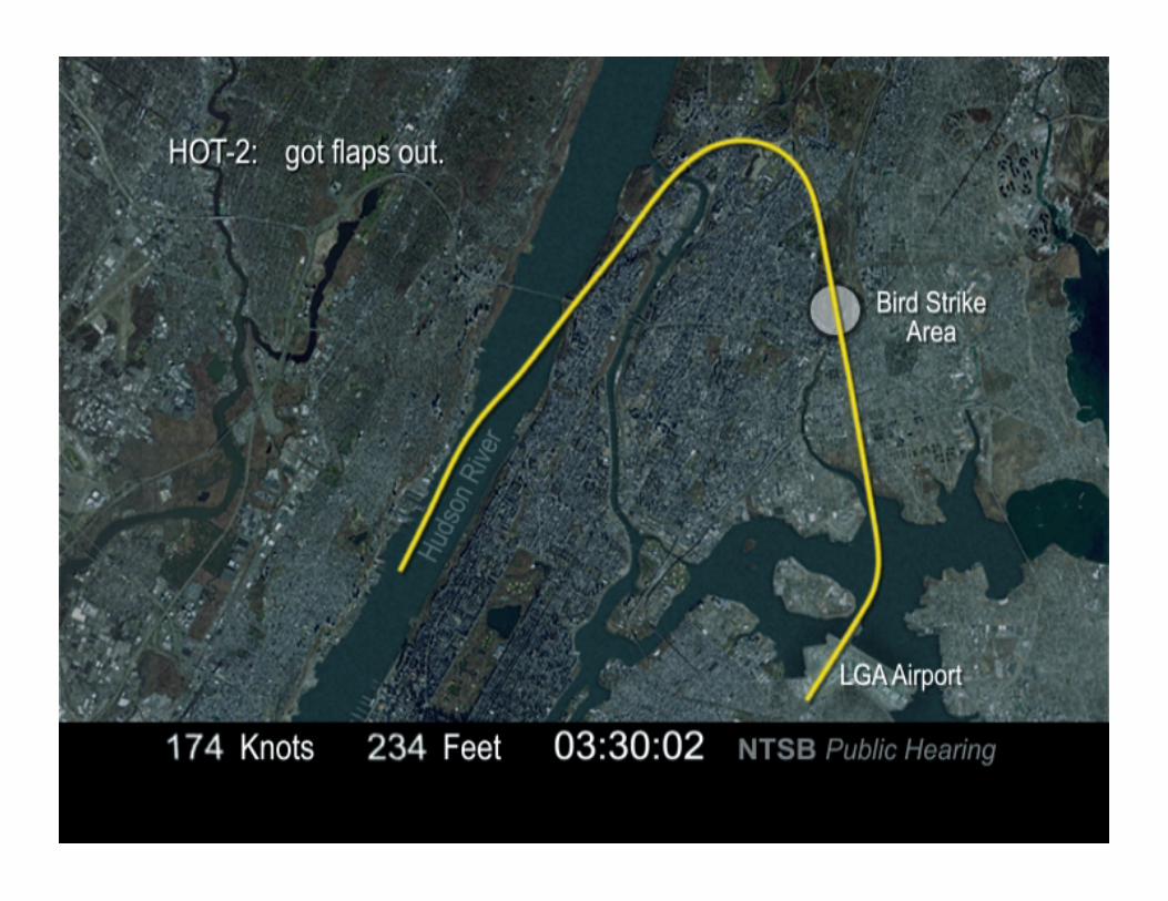
15:30:01 HOT-2
got flaps out.
15:30:03 HOT-2
two hundred fifty feet in the air.
15:30:04 GPWS
too low. terrain.
15:30:06 GPWS
too low. gear.
15:30:06 CAM-2
hundred and seventy knots.
15:30:09 CAM-2
got no power on either one? try the other one.
15:30:09 4718
two one zero uh forty seven eighteen. I think he said he's goin in the Hudson.
15:30:11 HOT-1
try the other one.
15:30:13 EGPWS
caution terrain.
15:30:14 DEP
Cactus fifteen twenty nine uh, you still on?

INTRA-COCKPIT COMMUNICATION AIR-GROUND COMMUNICATION TIME and TIME and SOURCE CONTENT SOURCE CONTENT
DCA09MA026 CVR Group Chairman’s Factual Report
Page 46 of 47
15:30:15 FWC
[sound of continuous repetitive chime begins and continues to end of recording]
15:30:15 EGPWS
caution terrain.
15:30:16 HOT-2
hundred and fifty knots.
15:30:17 HOT-2
got flaps two, you want more?
15:30:19 HOT-1
no lets stay at two.
15:30:21 HOT-1
got any ideas?
15:30:22 DEP
Cactus fifteen twenty nine if you can uh....you got uh runway uh two nine available at Newark it'll be two o'clock and seven miles.
15:30:23 EGPWS
caution terrain.
15:30:23 CAM-2
actually not.
15:30:24 EGPWS
terrain terrain. pull up. pull up. ["pull up" repeats until the end of the recording]
15:30:38 HOT-1
we're gonna brace.

INTRA-COCKPIT COMMUNICATION AIR-GROUND COMMUNICATION TIME and TIME and SOURCE CONTENT SOURCE CONTENT
DCA09MA026 CVR Group Chairman’s Factual Report
Page 47 of 47
15:30:38 HOT-2
* * switch?
15:30:40 HOT-1
yes.
15:30:41.1 GPWS
(fifty or thirty)
15:30:42 FWC
retard.
15:30:43.7 [End of Recording] 15:30:43.7 [End of Transcript]

FACTUAL REPORT DCA09MA004
Docket No. SA-532
Exhibit No. 2-A
NATIONAL TRANSPORTATION SAFETY BOARD
Washington, D.C.
Operations/Human Performance Group Chairmen Factual Report
(34 Pages)
FACTUAL REPORT DCA09MA004
NATIONAL TRANSPORTATION SAFETY BOARD
Office of Aviation Safety Washington, D.C. 20594
May 15, 2009
Group Chairmen’s Factual Report
OPERATIONS / HUMAN PEFORMANCE
DCA09MA026

FACTUAL REPORT DCA09MA026 1
A. ACCIDENT
Operator: US Airways Group, Inc. Location: Hudson River, New York, New York Date: January 15, 2009 Time: 1527 eastern standard time1 Airplane: Airbus A320-214, Registration Number: N106US, Serial #: 1044
B. OPERATIONS/HUMAN PERFORMANCE GROUP
David Helson – Co-Chair Operational Factors Division (AS-30) National Transportation Safety Board 490 L’Enfant Plaza East, SW Washington, DC 20594-2000
Katherine Wilson – Co-Chair Human Performance Division (AS-60) National Transportation Safety Board 490 L’Enfant Plaza East, SW Washington, DC 20594-2000
Ricky L. Daniel – Member New York Flight Standards Federal Aviation Administration 990 Stewart Avenue, Suite 630 Garden City, NY 11530
Lori L. Cline – Member A320 Check Airman/APD US Airways 4800 Hangar Road Charlotte, NC 28208
Lawrence J. Rooney Jr. – Member Accident Investigation Committee Vice Chairmen US Airline Pilots Association 5821 Fairview Road, Suite 400 Charlotte, NC 28209
Philippe Boscardin – Member2 Pilot Inspector French Civil Aviation Authority Representing BEA 50 rue Henry Farman 75720 Paris CEDEX 15 France
Terry Lutz – Member Airbus EVC 1 Rond Point Maurice Bellonte 31707 Blagnac CEDEX France
C. SUMMARY On January 15, 2009, about 1527 eastern standard time, US Airways flight 1549, an Airbus A320-214, registration N106US, suffered bird ingestion into both engines, lost engine thrust, and landed in the Hudson River following take off from New York City's La Guardia Airport (LGA). The scheduled, domestic passenger flight, operated under the provisions of Title 14 CFR Part
1 All times are eastern standard time (EST) based on a 24-hour clock, unless otherwise noted. Actual time of accident is approximate. 2 Mr. Boscardin arrived at the NTSB command post in New York City on January 17. Mr. Boscardin took part in the investigative activities with the group until the Operations/Human Performance group completed the field phase of the investigation in Charlotte, North Carolina on January 22, 2009.

FACTUAL REPORT DCA09MA026 2
121, was en route to Charlotte Douglas International Airport (CLT) in Charlotte, North Carolina. The 150 passengers and 5 crewmembers evacuated the airplane successfully. One flight attendant and four passengers were seriously injured. D. DETAILS OF THE INVESTIGATION The National Transportation Safety Board (NTSB) investigators on the Operations/Human Performance Group traveled to New York City on Thursday, January 15, 2009. The group conducted the initial field phase of the investigation from the NTSB command post located at a hotel in downtown New York City, from January 16 to January 19, 2009. On January 16, 2009, the group gathered available flight documents for review, conducted an initial review of the Quick Reference Handbook (QRH), coordinated schedule of interviews, and requested company manuals, checklists, weight and balance data for the flight, and flight crew training and personnel records from US Airways. The group also requested flight crew medical and certification records from the Federal Aviation Administration (FAA), conducted interviews with two pilots of other companies who were passengers on the accident flight, and gathered information for the 72-hour history of the accident flight crew. From January 17 through January 19, 2009, the group conducted interviews with the accident captain, the accident first officer, and a pilot of an airplane that was descending to land at LGA about the time of the accident. The group also interviewed two helicopter pilots who were operating two separate tour helicopters and witnessed the accident airplane’s descent toward the Hudson River, as well as portions of the post-ditching evacuation. On January 19, 2009, the group chairs documented the contents of flight crew bags, inspected the wreckage of the accident airplane, and photo documented the contents of the flight deck and the flight deck controls and switches. The group traveled to Charlotte, North Carolina, on January 20, 2009, and conducted the remainder of the field phase of the investigation from the US Airways Training Center from January 20 through January 22, 2009. The group conducted interviews with US Airways Training Department personnel at the training center. The interviews included a ground instructor, and an instructor pilot, each of whom was involved in the accident first officer’s recent Airbus training. Additional interviews were conducted with the check pilot who administered the first officer’s Airbus qualification event and the check pilot who flew with the first officer during his initial operating experience (OE) on the Airbus. Interviews were also conducted with the US Airways’ Manager of AQP (Advanced Qualification Program), the Airbus fleet captain, and the director of Flight Safety. The group was given a tour of the US Airways Training Center that included a demonstration of the integrated procedures trainer (IPT) used in the training program. In addition, members of the

FACTUAL REPORT DCA09MA026 3
group observed a recreation of the accident in an airplane flight simulator and maneuvered the flight simulator during a recreation with a US Airways check airman. After completion of the on-scene phase of the investigation, the group conducted numerous interviews via telephone from NTSB headquarters. The investigation included follow up interviews with some interviewees from the field investigation as well as interviews with flight crew members who had flown with the accident crew, a flight crew who had encountered a compressor stall while operating the accident airplane two days prior to the accident, the FAA A320 aircrew program manager (APM) and principle operations inspector (POI) having oversight of US Airways, and the vice president of Flight Operations Support & Services at Airbus. Members of the group, along with the Aircraft Performance group chairman, traveled to Toulouse, France, to conduct simulator evaluations at the Airbus Training Center. Simulator scenarios were conducted in a Full Flight Simulator and an engineering test simulator. The purpose of the simulations were to (1) identify and evaluate the various options available to the flight crew of US Airways flight 1549 following the bird strike and to determine the implications of each of those options, (2) to expand beyond the context of flight 1549 in order to understand the implications of a dual engine failure in which the airplane is in the ELEC EMER CONFIG3, (3) to evaluate the checklists and procedures made available to flight crews, and (4) to determine the operational feasibility of achieving minimum vertical speed at touchdown. E. FACTUAL INFORMATION
1.0 History of Flight On January 13, 2009, a flight crew reportedly experienced an engine compressor stall while flying the accident airplane on a flight from LGA to CLT. According to the flight crew, the QRH procedure was accomplished and the engine compressor stall did not reoccur. That flight was continued, uneventfully, to CLT where the experience was reported to company maintenance personnel. According to US Airways, maintenance personnel inspected the airplane, performed required maintenance actions, and the airplane was returned to service. On January 15, 2009, after flying from Pittsburg International Airport (PIT) to CLT on a different airplane, the accident flight crew picked up the accident airplane for a flight to LGA. Except for delays due to snow in the New York area, the flight from CLT to LGA was reported to be uneventful. By the time the flight arrived in LGA, the weather had cleared and the flight crew stated that no deicing of the airplane was necessary prior to the accident flight.
3 “ELEC EMER CONFIG” refers to the emergency electrical mode in which no electrical power is available from either main generator or from the Auxiliary Power Unit. The Ram Air turbine is deployed either automatically or manually and provides blue hydraulic system pressure (normally provided by the blue electric pump), to power an emergency generator through a hydraulic motor. In this configuration, neither green nor yellow hydraulics are available on the airplane due to a loss of engine power.

FACTUAL REPORT DCA09MA026 4
The accident flight was scheduled to depart the gate in LGA at 1445 but due to the earlier delays, the flight departed at about 1503. The flight crew stated that they started both engines during the push back from the gate and they contacted the company during the taxi out to complete the final weight and balance. According to the crew, all required pre-departure checklists and procedures were completed during the taxi out to runway 4. According to the crew of the airplane sequenced for departure immediately behind the accident flight, the accident airplane was held on runway 4 for about 3-4 minutes prior to being cleared for takeoff. The delay was reported to be for a vehicle on the runway that was clearing ice that was deposited on the runway as a result of a previous landing airplane on the crossing runway. The accident flight was cleared by air traffic control (ATC) for takeoff on runway 4 and instructed to fly heading 360 after departure and climb to 5,000 feet. The accident flight commenced the takeoff roll with the first officer as the pilot flying. After reaching the acceleration altitude, the crew selected flaps up to configure the airplane for climb, completed the after takeoff checklist, and received a radio frequency change to departure control. According to the flight crew, the climb out was uneventful until reaching an altitude between 3,000 and 5,000 feet. The first officer stated that he saw a line of birds in formation that appeared to be passing beneath the airplane flight path. The captain stated that he looked up and saw birds that filled his field of view. Both flight deck crewmembers reported hearing multiple impacts that they assumed were birds, followed by a burning smell in the airplane. The crew stated that there was an immediate loss of thrust in both engines. According to the crew, the captain turned on the engine ignition, started the auxiliary power unit (APU), took over control of the airplane4 and called for the ENG DUAL FAILURE checklist procedure. The first officer began to apply the procedure as the captain maneuvered the airplane and communicated with ATC. According to the crew, attempts to re-establish thrust from the engines were unsuccessful. The airplane ditched in the Hudson River about 1531. The cabin and flight deck crew initiated evacuation of the airplane. All crewmembers and passengers were evacuated from the airplane and were picked up by ferry boats that were operating in the vicinity. 2.0 Flight Crew Information
The accident flight crew consisted of a captain, first officer, and three cabin crewmembers. The captain and first officer (F/O) had not flown together prior to this pairing. The accident flight was the last flight of a 4-day trip.
4 See attachment 16 – Captain’s Authority

FACTUAL REPORT DCA09MA026 5
2.1 The Captain The captain was 57 years old, married, with two children, ages 14 and 16. He lived near San Francisco, California. He learned to fly in 1967 and had a private, commercial, instrument, and certified flight instructor (CFI) certificate prior to completing college. He flew F-4 airplanes in the US Air Force prior to being hired by Pacific Southwest Airlines (PSA) on February 25, 1980, which merged with USAir in 1988. He reported 19,500 hours total flight experience with about 3,800 hours in the Airbus. A US Airways first officer who flew with the captain on a six-leg trip on December 28, 2008, described him as exceptionally intelligent, polite and professional. The captain’s proficiency check records were satisfactory. The captain stated he was in excellent health. His last medical certificate, dated December 1, 2008, contained no restrictions. He had visited a surgeon for blepharoplasty during the previous 6 months, but reported no other changes to his health. He was not taking prescription medications at the time of the accident, and stated that he had not taken any medications in the 72 hours before the accident. He drank alcohol occasionally, but had not had any alcohol in the week and a half before the accident. The captain had not had any major changes to his health, financial situation or personal life, good or bad, in the last year. When he was not working, the captain typically went to sleep around 2300 and awoke around 0700. The captain was current and qualified under US Airways and FAA requirements. A review of FAA records found no prior accident, incident or enforcement actions. A search of records at the National Driver Registry (NDR) found no history of driver’s license revocation or suspension.
2.1.1 The Captain’s Pilot Certification Record FAA records of the captain indicated that: Private Pilot - Airplane Single Engine Land certificate was issued on October 28, 1968. Commercial Pilot – Airplane Single Engine Land certificate was issued on May 24, 1969. Student Pilot – Passenger Carrying Prohibited: Glider Only certificate was issued on November
10, 1970. Flight Instructor - Airplanes certificate was originally issued on July 1, 1971. Commercial Pilot – Airplane Single Engine Land - Glider certificate was issued on July 23,
1971. Flight Instructor - Airplane and Glider certificate was originally issued on December 16, 1971. Commercial Pilot – Airplane Single and Multi Engine Land – Glider certificate was issued on
August 14, 1972. Commercial Pilot – Airplane Single and Multi Engine Land – Glider – Instrument certificate was
issued on November 17, 1972. Ground Instructor – Advanced Ground Instructor – Instrument Ground Instructor certificate was
issued on June 7, 1973. Flight Instructor - Airplane Single Engine – Instrument Airplane - Glider certificate was
originally issued on September 3, 1975.

FACTUAL REPORT DCA09MA026 6
Flight Instructor - Airplane Single and Multi Engine – Instrument Airplane - Glider certificate was originally issued on October 31, 1977.
Airline Transport Pilot – Airplane Single and Multiengine Land – Commercial Pilot Privileges – Glider certificate was issued on April 18, 1978. A LR-JET type rating was added on September 15, 1981. A BAE-146 type rating was added on March 25, 1988. A B-737 type rating was added on July 18, 1990. A DC-9 type rating was added on January 18, 1995. An AVR-146 and an A-320 Circling Approach VMC only type rating were added on August 7, 2002.
Flight Engineer – Turbojet Powered certificate was issued on May 13, 1980.
2.1.2 The Captain’s Pilot Certificates and Ratings Held at Time of the Accident AIRLINE TRANSPORT PILOT (issued August 07, 2002) AIRPLANE SINGLE and MULTIENGINE LAND AVR-146, B-737, BAE-146, DC-9, LR-JET, A-320 CIRC APCH VMC ONLY COMMERCIAL PRIVILEGES GLIDER FLIGHT ENGINEER (issued May 13, 1980) TURBOJET POWERED MEDICAL CERTIFICATE FIRST CLASS (issued December 1, 2008) Limitations: None
2.1.3 The Captain’s Training and Proficiency Checks Completed Initial Type Rating Airbus A320: August 7, 2002 Last recurrent simulator training: February 20, 2008 Last recurrent ground training: February 19, 2008 Last Line Check in A320: December 27, 2007 Last Proficiency Check: February 21, 2008
2.1.4 The Captain’s Flight Times The captain’s flight times, based on US Airways employment records:
Total pilot flying time 19,663 hours Total Pilot-In-Command (PIC) time 8,930 hours Total A320 flying time 4,765 hours Total A320 PIC time 4,765 hours Total flying time last 24 hours 4 hours, 59 minutes Total flying time last 7 days 20 hours, 12 minutes Total flying time last 30 days 39 hours, 26 minutes Total flying time last 60 days 82 hours, 44 minutes

FACTUAL REPORT DCA09MA026 7
Total flying time last 90 days 154 hours, 55 minutes Total flying time last 12 months 782 hours, 30 minutes
2.1.5 The Captain’s 72-Hour History On January 12, 2009, the captain began a 4-day pairing with the accident F/O. He had not been on duty since December 31, 2008. The flight crew began their trip in CLT at 1806 EST and flew to SFO, arriving at 2119 PST. The captain lived in the San Francisco area and he spent the evening at his home. He went to bed around 2300 PST. He said he needed about 8 hours of sleep to feel rested. On January 13, 2009, the captain awoke at 0700 PST. He had breakfast with his children, after which he got ready for work. He left his house at 1100 PST for a 1220 PST show time at the airport. The flight crew departed SFO at 1315 PST and arrived in PIT at 2103 EST (all times hereafter are EST). The captain went to the hotel from the airport. He said the total layover time was 9 hours and 58 minutes but that did not include check in and check out. He did not recall what time he went to bed. On January 14, 2009, the captain awoke at 0510 for a 0600 departure from the hotel. He had a 0705 flight departure from PIT to LGA. He ate breakfast at the hotel. He said his quality of sleep on the previous night was good or average. He said it was a short night and he did not get 8 hours of sleep but that that was ok. He said it felt normal. The flight crew flew from PIT to LGA and back to PIT. The captain said they had a long layover and spent the night at a hotel in downtown Pittsburgh. He went for a walk around town, ate dinner and answered some emails. He went to bed fairly early, probably about 2200. On January 15, 2009, the captain awoke at 0640 for a 0730 van departure from downtown Pittsburgh. The accident crew had a 0900 departure. He said his sleep was good and he was fortunate to be a good sleeper. He was a sound sleeper and said he felt rested. The captain ate breakfast at the airport. The flight crew departed PIT at 0856 after being deiced and arrived in CLT at 1055. The flight crew was excited to fly the newest A321. The flight crew changed airplanes in CLT. The captain did not get anything to eat in CLT. The flight was delayed 75 minutes due to ATC delays. The flight crew departed CLT at 1154 and arrived in LGA at 1423. The captain said they had a quick turn at LGA so he purchased a sandwich to eat on the airplane after departure. The flight crew departed LGA for CLT at 1503.
2.2 The First Officer The F/O was 49 years old. He lived near Madison, Wisconsin. He learned to fly when he was 15 or 16 years old and flew only in civilian aviation. He was hired by USAir on April 7, 1986. He reported about 20,000 hours total flight experience with about 35 hours in the Airbus. The F/O stated he received a commendation letter from the director of operations years ago for making great PA announcements. A US Airways check airman that flew with the F/O for his OE, a 4-day trip on January 5, 2009, described him as a very good pilot, and stated the F/O came out well trained. The F/O’s proficiency check records were satisfactory.

FACTUAL REPORT DCA09MA026 8
The F/O said that he was in good health. His last medical certificate, dated October 7, 2008, contained a limitation for corrective lenses, and he stated he was wearing corrective contact lenses at the time of the accident. He was not taking prescription medications at the time of the accident, and stated that he had not taken any medications in the 72 hours before the accident. He had not had an alcoholic beverage in 10 years. The F/O had not had any major changes to his health, financial situation or personal life, good or bad, in the last year. The F/O stated he typically needed 7 hours of sleep to feel rested. The F/O was current and qualified under US Airways and FAA requirements. A review of FAA records found no prior accident, incident or enforcement actions. A search of records at the NDR found no history of driver’s license revocation or suspension.
2.2.1 The F/O’s Pilot Certification Record FAA records of the F/O indicated that: Private Pilot - Airplane Single Engine Land certificate was issued on November 18, 1976. Private Pilot - Airplane Single Engine Land – Instrument Airplane certificate was issued on
December 17, 1978. Commercial Pilot – Airplane Single Engine Land and Sea – Instrument Airplane certificate was
issued on February 27, 1979. Flight Instructor - Airplane Single Engine certificate was originally issued on May 10, 1979. Flight Instructor - Airplane Single Engine – Instrument Airplane certificate was originally issued
on August 2, 1979. Commercial Pilot – Airplane Single and Multi Engine Land – Instrument Airplane certificate
was issued on October 20, 1979. Flight Instructor – Airplane Single and Multi Engine – Instrument Airplane was originally issued
on August 25, 1981. Flight Engineer – Turbojet Powered – (Subject to Provisions Of Exemption No. 2095 As
Amended) certificate was issued on May 23, 1986. Flight Engineer – Turbojet Powered certificate was issued on June 16, 1986. Airline Transport Pilot – Airplane Multi-Engine Land – Commercial Pilot Privileges – Airplane
Single Engine Land certificate was issued on November 19, 1982. A FK-100 type rating was added on June 12, 2000 and a B-737 type rating was added on March
24, 2002.
2.2.2 The F/O’s Pilot Certificates and Ratings Held at Time of the Accident AIRLINE TRANSPORT PILOT (issued December 31, 2008) AIRPLANE MULTIENGINE LAND B-737, FK100, A-320 COMMERCIAL PRIVILEGES AIRPLANE SINGLE ENGINE LAND

FACTUAL REPORT DCA09MA026 9
Fk-100, B-737, A-320 Circ. Appr. VMC ONLY FLIGHT ENGINEER (issued June 16, 1986) TURBOJET POWERED MEDICAL CERTIFICATE FIRST CLASS (issued October 7, 2008) Limitations: Holder shall wear corrective lenses while exercising the privileges of this certificate
2.2.3 The F/O’s Training and Proficiency Checks Completed Initial Type Rating A320: December 31, 2008 Last recurrent simulator training: Not Applicable Last recurrent ground training: Not Applicable Last line check on A320: January 8, 2009 Last Proficiency check on A320: December 31, 2008
2.2.4 The F/O’s Flight Times The accident F/O’s flight times, based on US Airways employment records:
Total pilot flying time 15,643 hours Total PIC time 1,001 hours Total SIC time 8,977 hours Total flying time in A320 36 hours, 37 minutes Total A320 second-in-command (SIC) time 36 hours, 37 minutes Total flying time last 24 hours 4 hours, 59 minutes Total flying time last 7 days 20 hours, 12 minutes Total flying time last 30 days 37 hours, 8 minutes Total flying time last 60 days 55 hours, 4 minutes Total flying time last 90 days 124 hours, 21 minutes Total flying time last 12 months 630 hours, 0 minutes
2.2.5 The F/O’s 72-Hour History On January 12, 2009, the F/O began a 4-day pairing with the accident captain. The F/O had been off for the 3 days prior to this pairing. The flight crew departed from CLT at 1806 EST and arrived in SFO at 2119 PST. The F/O said he was not tired when he arrived at the hotel so he went out and walked for an hour. He came back to the hotel and went to bed. He estimated that he was walking around 2200 PST and went to bed around 2300 PST, but was not sure. On January 13, 2009, the F/O did not recall when he awoke but said he felt rested. He said he got up and walked 5-6 miles. He came back and spent some time in the hotel room before going to

FACTUAL REPORT DCA09MA026 10
the airport. The flight crew flew from SFO to PIT for a short layover. He said he stayed at a hotel and had less than 8 hours in PIT. He did not recall when he went to bed. On January 14, 2009, the F/O awoke at 0510 EST (all times hereafter are EST) for a 0600 van. The accident crew flew from PIT to LGA and back to PIT. He said the flight crew had a long layover in PIT and they stayed in a hotel downtown. He walked to see a movie and then walked back to the hotel. He did not recall when he went to bed. On January 15, 2009, the F/O awoke at 0640 and felt rested. The quality of his sleep was good. He did not eat breakfast which he said was typical. He left the hotel at 0730. The flight crew departed PIT for CLT at 0856 and arrived in CLT at 1055. The flight crew switched airplanes in CLT. The F/O ate in the airport. The flight crew departed CLT at 1154 and arrived at LGA at 1423. In LGA, the F/O got off the airplane and did the walk around. The turn was quick because the flight in to LGA arrived late. The flight crew departed LGA for CLT at 1503. 2.3 Medical and Pathological Information
2.3.1. The Flight Crew’s Post-Accident Toxicological Testing On the evening of January 15, 2009, the captain and F/O complied with a company request to provide urine specimens for drug testing and to participate in breathalyzer tests. US Airways reported that these tests yielded no evidence of drug or alcohol use.5 3.0 Weight and Balance The following information was obtained from the US Airways weight manifest (unless otherwise noted):
Basic Operating Weight 98,000 lbs Passenger Weight 29,250 lbs Baggage & Cargo 2,910 lbs Zero Fuel Weight 130,160 lbs Fuel 22,100 lbs Ramp Weight 152,260 lbs Taxi Fuel Burn 750 lbs Takeoff Weight 151,510 lbs Maximum Takeoff Weight Allowed 151,600 lbs
5 US Airways provided results certificates to the Safety Board indicating that both pilots tested negative for the following drugs: marijuana, cocaine, amphetamines, opiates, and PCP. The certificates stated that the captain and first officer performed a breathalyzer at 2205 and 2221, respectively, on January 15, 2009, and the test results were negative.

FACTUAL REPORT DCA09MA026 11
Estimated Ditching Weight 150,000 lbs6 US Airways used a computerized weight and balance system provided under contract by electronic data systems (EDS), and included a load planning system (LPS), a takeoff performance system (TPS), and a flight planning system (FPS). The TPS was the primary tool utilized to assure that the structural loading limits, takeoff weight limits, and the center of gravity (CG) limits were not exceeded on an airplane for a particular flight.7 The Operations/Human Performance Group obtained weight and balance data for the accident flight and determined, using Airbus performance data and manuals that the takeoff CG and weight was within the approved limits of the airplane for takeoff from runway 4 at LGA. 4.0 Aerodrome Information Airport information was obtained from the Federal Aviation Administration’s National Aeronautical Charting Office (NACO) Terminal Procedures Publication (TPP) and Airport Facility Directory (AFD). At the time of the bird strike, the nearest suitable airports to the accident airplane were LGA and Teterboro Airport (TEB). The accident airplane collided with birds about 40° 50’ 53.16” N, 73° 52’ 33.92” W which was about 4.5 miles from the approach end of LGA runway 22 and about 9.5 miles from the approach end of TEB runway 24. The point of touchdown in the Hudson River was about 40° 46’ 16.67” N, 74° 00’ 20.51” W. The distance from the point of impact with the birds to the point of touchdown in the Hudson River was about 8.5 miles. 5.0 Company Overview US Airways, Inc. was an operating unit of US Airways Group headquartered in Tempe, Arizona, and was certificated as a Federal Aviation Regulation (FAR) part 121 air carrier for both domestic and flag operations. At the time of the accident, US Airways had major hubs at CLT, Philadelphia International Airport (PHL), and Phoenix Sky Harbor International Airport (PHX), and operated over 300 airplanes manufactured by The Boeing Company, Airbus Industrie, and Embraer. According to information provided on the company’s web site,8 US Airways began passenger service in 1949 as All American Airways. In 1953, All American Airways changed its name to Allegheny Airlines and to USAir in 1979. In 1988, USAir Group merged with Pacific Southwest Airlines (PSA) and with Piedmont Airlines in 1989, which was known as the largest merger in airline history. USAir Group became US Airways Group in 1997. In 1999, US Airways acquired its first A320 airplane and offered daily scheduled service between PHL and Los Angeles
6 Estimated Ditching Weight based on takeoff weight minus estimated fuel burn in climb to 3,000 feet and descent at idle thrust. 7 US Airways Weight and Balance Analysis and Methodology Manual, p. 27. 8 Information received from website of US Airways <http://www.usairways.com/awa/content/aboutus/pressroom/history/chronology.aspx> (accessed May 6, 2009)

FACTUAL REPORT DCA09MA026 12
International Airport (LAX). US Airways Group, Inc. filed for reorganization under Chapter 11 of the US Bankruptcy code in 2004 (the second time since 2002), and a similar process was being considered by America West Airlines. In 2005, US Airways Group, Inc. merged with America West Holdings, and following the merger, US Airways Group, Inc. was no longer in bankruptcy. The accident airplane was owned by Wells Fargo Bank Northwest NA Trustee, and operated by US Airways for FAR Part 121 passenger carrying operations. 6.0 Bird Strike Hazard In 1999, the NTSB issued Safety Recommendation A-99-091 which recommended that all operators be required to report bird strikes to the FAA. The recommendation was not accepted and at the time of this accident, bird strike reporting was voluntary. The FAA maintained a database which contained information on bird strikes to civil airplanes. The FAA National Wildlife Strike Database contained strike reports that were voluntarily reported to the FAA by pilots, airlines, airports and others. At the time of the accident, research indicated that only about 20 percent of bird strikes were reported.9 The database indicated that the total number of reported bird strikes to airplanes had increased from 1,738 in 1990 to over 7,400 in 2007, and that 92 percent of the strikes occurred below 3,000 feet agl (above ground level). The US Airways Flight Operations Manual (FOM), chapter 4.16.2, page 4-23, included guidance for pilots to notify the controlling dispatcher following a bird strike on any flight. Additional guidance on page 4-31 of the FOM required a flight crew member to notify the controlling dispatcher as soon as practical, to make an entry in the FDML (flight deck maintenance log), and to complete an Event/ASAP (Aviation Safety Action Program) report within 48 hours of completing the trip. 7.0 ECAM and QRH The Airbus A320 was equipped with an electronic centralized aircraft monitor (ECAM) system which presented data on the flight deck engine/warning display (E/WD) and the system display (SD). In the event that an airplane system failure was detected by the flight warning computer (FWC), the E/WD displayed the title of the failure and actions to be taken by the crew. The failure message may also be accompanied by an aural warning and/or master caution or warning lights on the flight deck.
9 Information received from website of FAA National Wildlife Strike Database <http://wildlife-mitigation.tc.faa.gov> (accessed May 6, 2009).

FACTUAL REPORT DCA09MA026 13
In certain instances, an abnormal procedure could not be sensed by the ECAM, or the procedure presented on the ECAM did not include actions to be taken that were added after the original design specifications of the airplane. The US Airways Quick Reference Handbook (QRH) was carried on board the airplane and included abnormal and emergency procedures, including those that could not be sensed by, or presented on the ECAM system, and expanded procedures to be used in the event that an ECAM procedure was identified where it was recommended that the QRH be used. The US Airways QRH included six procedures for which a QRH procedure must be used in lieu of an ECAM action. These six procedures were referred to as “ECAM Exceptions”. The US Airways QRH contained immediate action items, an index of ECAM procedures, an alphabetical listing of procedures contained in the QRH. On the back cover of the QRH was a list of immediate action items and ECAM Exceptions10 with reference to page numbers where each procedure was located. 8.0 Non-Normal Procedures/Methodology Non-normal procedures and non-normal methodology were contained in the US Airways A319/320/321 Pilot Handbook (PH) Chapter 9: Non-Normal Operations. Page 9-5 of the PH stated in part:
9.1.4 Procedures. When a non-normal situation is evident, methodically accomplish the following steps: 1. PF - Maintain Aircraft Control 2. Identify the Non-normal PM - Cancels the Warning or Caution, if applicable 3. PM - Determine if Immediate Action or ECAM Exception 4. PM - Accomplish Immediate Action Items, if applicable 5. Captain - Assigns PF 6. PM - Accomplish Non-normal procedure 7. PM - Accomplish ECAM Follow-Up procedures, if applicable
The expanded step 3 was presented on page 9-6 of the PH and stated in part: 3. PM - Determine if Immediate Action or ECAM Exception.
Once: — the airplane flightpath and configuration are properly established, and — the airplane is not in a critical phase of flight (e.g., takeoff, landing), the PM
determines and verbalizes whether the non-normal is an Immediate Action Item
10 See attachment 8 – ECAM Exceptions

FACTUAL REPORT DCA09MA026 14
or an ECAM Exception. The Immediate Action Index and ECAM Exception Index are available on the back of the QRH.
9.0 Dual Engine Failure Interviews conducted with Airbus personnel indicated that the Airbus ENG DUAL FAILURE11 checklist was amended in 2004. As part of the Airbus Continuing Improvement Process, procedures previously located in different checklists were incorporated into the Airbus ENG DUAL FAILURE procedure. One improvement noted during interviews was to differentiate between a no fuel remaining and a fuel remaining scenario. US Airways ENG DUAL FAILURE12 checklist was based on the Airbus checklist but was designed by US Airways personnel and approved for use by the FAA.
9.1 Operator Procedures and Checklist Following the bird strike, the captain took control of the airplane and called for the dual engine failure checklist. The F/O, having recently been through training, recognized the event as an ECAM exception and promptly found the procedure listed on the back cover of the US Airways QRH. The title of the procedure was ENG DUAL FAILURE and was located on pages 27 through 29 of the QRH. In accordance with US Airways procedures, the flight crew elected to follow the QRH procedure in lieu of the ECAM procedure. The F/O executed the procedure.13 The US Airways ENG DUAL FAILURE procedure14 incorporated three parts. Part 1 of the procedure required the crew to differentiate between a “no fuel remaining” and a “fuel remaining” condition and included steps to attempt an engine re-start. According to crew statements, the flight crew elected to follow the steps for a fuel remaining condition. Part 2 of the procedure included guidance to follow in the event an engine restart was successful and guidance and procedures to configure airplane systems in the event that an engine restart was not possible. Part 3 of the procedure contained guidance and procedures to follow in the event a forced landing was anticipated, or in the event a ditching was anticipated. According to crew statements and due to the low altitude and limited time available, the crew was unable to initiate part 2 or part 3 of the ENG DUAL FAILURE checklist. The US Airways QRH, page 27, of the ENG DUAL FAILURE procedure stated in part:
11 See attachment 9 – Airbus QRH DUAL ENG FAILURE 12 See attachment 10 – US Airways QRH ENG DUAL FAILURE 13 See attachment 1 – Flight Crew Interviews 14 See attachment 10 – US Airways QRH ENG DUAL FAILURE
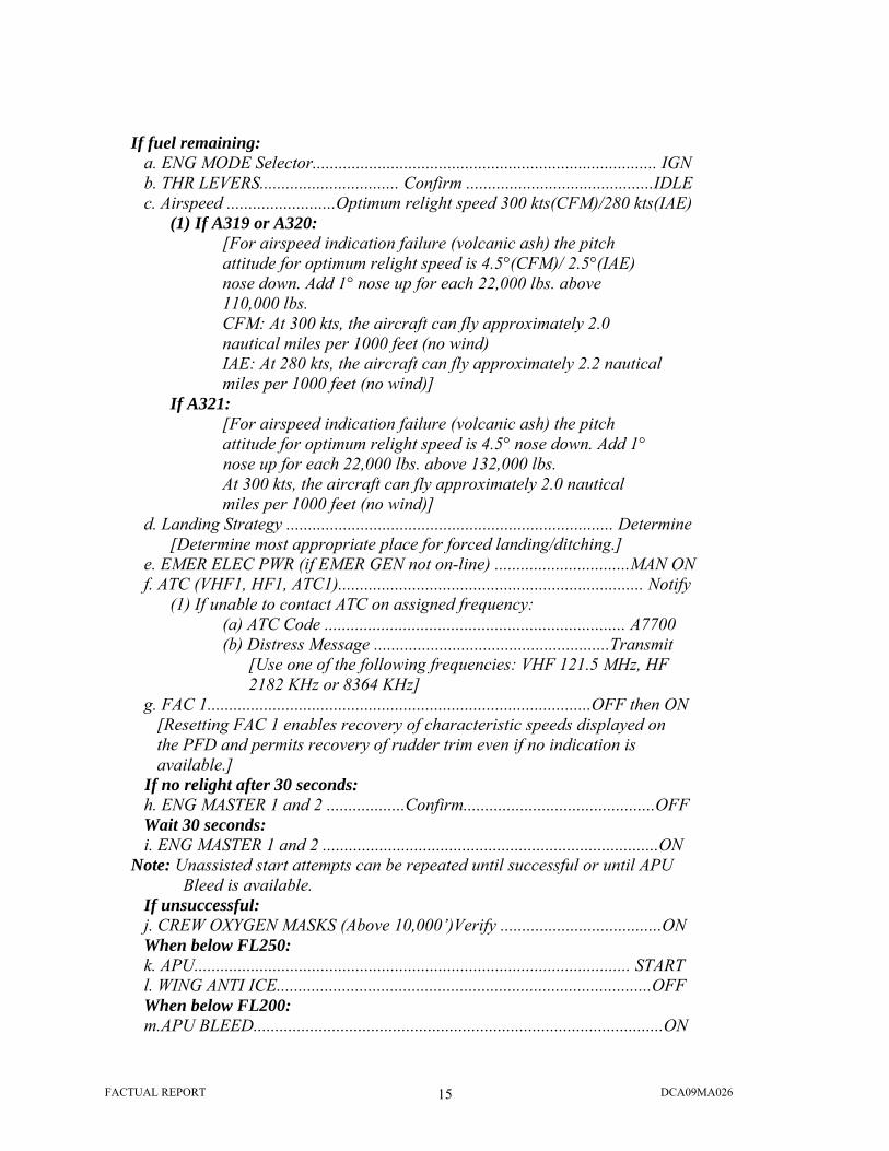
FACTUAL REPORT DCA09MA026 15
If fuel remaining:
a. ENG MODE Selector............................................................................... IGN b. THR LEVERS................................ Confirm ...........................................IDLE c. Airspeed .........................Optimum relight speed 300 kts(CFM)/280 kts(IAE)
(1) If A319 or A320: [For airspeed indication failure (volcanic ash) the pitch attitude for optimum relight speed is 4.5°(CFM)/ 2.5°(IAE) nose down. Add 1° nose up for each 22,000 lbs. above 110,000 lbs. CFM: At 300 kts, the aircraft can fly approximately 2.0 nautical miles per 1000 feet (no wind) IAE: At 280 kts, the aircraft can fly approximately 2.2 nautical miles per 1000 feet (no wind)]
If A321: [For airspeed indication failure (volcanic ash) the pitch attitude for optimum relight speed is 4.5° nose down. Add 1° nose up for each 22,000 lbs. above 132,000 lbs. At 300 kts, the aircraft can fly approximately 2.0 nautical miles per 1000 feet (no wind)]
d. Landing Strategy ........................................................................... Determine [Determine most appropriate place for forced landing/ditching.]
e. EMER ELEC PWR (if EMER GEN not on-line) ...............................MAN ON f. ATC (VHF1, HF1, ATC1)...................................................................... Notify
(1) If unable to contact ATC on assigned frequency: (a) ATC Code ..................................................................... A7700 (b) Distress Message ......................................................Transmit
[Use one of the following frequencies: VHF 121.5 MHz, HF 2182 KHz or 8364 KHz]
g. FAC 1........................................................................................OFF then ON [Resetting FAC 1 enables recovery of characteristic speeds displayed on the PFD and permits recovery of rudder trim even if no indication is available.]
If no relight after 30 seconds: h. ENG MASTER 1 and 2 ..................Confirm............................................OFF Wait 30 seconds: i. ENG MASTER 1 and 2 .............................................................................ON
Note: Unassisted start attempts can be repeated until successful or until APU Bleed is available.
If unsuccessful: j. CREW OXYGEN MASKS (Above 10,000’)Verify .....................................ON When below FL250: k. APU.................................................................................................... START l. WING ANTI ICE......................................................................................OFF When below FL200: m.APU BLEED..............................................................................................ON

FACTUAL REPORT DCA09MA026 16
Note: If APU Bleed is available, APU Bleed assisted starts may be accomplished at Green Dot Speed.
n. ENG MASTER 1 and 2 ..................Confirm............................................OFF Wait 30 seconds: o. ENG MASTER 1 and 2 (one at a time) .....................................................ON
Step “a.” in the procedure directed the crew to position the ENG MODE selector to the IGN position. The captain had already accomplished this step by memory prior to calling for the checklist. Step “b.” directed the crew to move the engine thrust levers to idle. Although the crewmembers could not recall which of them accomplished this task, both stated that the engine thrust levers were moved to the idle position. Step “c.” directed the crew to attain the “optimum relight speed” in order to attempt a windmilling15 restart of the engines. According to crew statements, the crew determined that due to the airspeed and low altitude at the time, they would be unable to reach the optimum relight speed. Step “d.” directed the crew to determine a landing strategy and included the following note:
Determine most appropriate place for forced landing/ditching. The captain stated in interviews that he determined, given the circumstances, a ditching in the Hudson River was the most appropriate strategy. (See section 13.4 “Landing Strategy” for more details.) Step “e.” required the selection of the RAT MAN ON16 switch if the emergency generator was not on line. Immediately following the loss of thrust in both engines, the captain had initiated the start sequence for the auxiliary power unit (APU). Preliminary digital flight data recorder (DFDR) information indicated that the airplane was not in the ELEC EMER configuration. The crew stated that they had determined electrical power was established. The captain complied with step “f.” when he notified ATC of the situation via radio. The F/O carried out step “g.” to reset the FAC 1.17 Step h.” directed the crew to select, after confirmation by both crewmembers, both engine master switches to the off position. According to crew statements, the number one engine appeared to still be operating at a reduced level. For this reason, the F/O opted to select only the number two engine master switch to off initially. The purpose of selecting the master switch to off was to reset the FADEC.18 The procedure also called for a delay of 30 seconds prior to selecting the master switch back to the on position in order to ventilate the engine combustion chamber before attempting a restart.
15 “Windmilling restart” refers to an emergency in-flight procedure in which the effect of ram airflow passing through the engine provides rotational energy to turn the engines core. 16 “RAT MAN ON” refers to the ram air turbine manual on. 17 “FAC 1” refers to the flight augmentation computer 1. 18 “FADEC” refers to the full authority digital engine control.

FACTUAL REPORT DCA09MA026 17
The F/O stated that he did not use a timing device and was not sure how long he waited before selecting the engine 2 master switch back to the on position in accordance with step “i.” of the procedure. The F/O stated that at some point after attempting the relight of engine number 2 and after determining that there was not much time remaining; he selected the engine 1 master switch to off. After a short delay, he selected the engine 1 master switch on to initiate a restart of that engine. According to crew statements, they were unable to continue beyond step “i.” of the procedure due to the short amount of time prior to landing.
9.2 Manufacturer Procedures and Checklist Interviews conducted with Airbus personnel indicated that, regarding the ECAM and QRH procedures, the Engine Dual Failure was an ECAM exception and Airbus recommended during training that the flight crew refer to the QRH procedure. The ENG DUAL FAILURE – FUEL REMAINING19 procedure was contained in the Airbus QRH pages 1.16 through 1.19. A note at the beginning of the procedure read as follows:
As long as none of the engines recover, the flight crew should apply this paper procedure and then, if time permits, clear ECAM alerts and check the ECAM STATUS page.
The procedure directed the crew to determine a landing strategy. The ENG DUAL FAILURE – FUEL REMAINING procedure stated in part:
LANDING STRATEGY…………………………………………………………….DETERMINE Determine whether a runway can be reached, or the most appropriate place for a forced landing/ditching.
The procedure contained in the Airbus QRH included steps to be taken to attempt an engine restart, and in the event an engine restart was not possible; steps to configure the airplane for a forced landing, and steps to configure the airplane for a ditching.
9.3 Airplane Configuration The US Airways QRH and the Airbus QRH ENG DUAL FAILURE procedures both provided guidance that indicated flaps 3 was to be used for ditching. In addition, the procedures directed the crew to configure the airplane for ditching prior to descending below 3,000 feet above ground level. The US Airways QRH, ENG DUAL FAILURE procedure, page 28 stated in part:
For landing............................................................................Use FLAPS 3 [Only slats will extend and operating time is noticeably increased, as
only blue hydraulic power is available from the RAT.]
19 See attachment 9 – Airbus QRH ENG DUAL FAILURE

FACTUAL REPORT DCA09MA026 18
And on page 29:
If Ditching is anticipated: Prior to 3,000’ AGL: a. FLAPS…………………………………………Configure for landing
The Airbus QRH, ENG DUAL FAILURE procedure, page 1.19 stated in part:
IF DITCHING ANTICIPATED APPROACH -FOR LANDING…………………………………………USE FLAPS 3 Only slats extend, and slowly.
And
At a suitable altitude (not below 3,000 feet AGL), configure the aircraft for ditching (CONF 320; L/G UP)
Preliminary information obtained from the DFDR indicated that the accident airplane lost thrust in both engines at about 3,000 feet agl. The crew stated that due to the limited time available, they did not reach the section of the checklist that provided guidance on airplane configuration. The flight crew elected to use flaps 2 for landing. The US Airways and Airbus checklist procedures both provided guidance indicating that only slats, and no flaps, were available21 following a failure of both engines due to the loss of the green and the yellow engine driven hydraulic pumps and resultant loss of hydraulic pressure in those systems. The Airbus FCOM volume 1 page 1.27.50 P 5 stated in part:
The FLAPS lever selects simultaneous operation of the slats and flaps. The five lever positions correspond to the following surface positions:
Position SLATS FLAPS Indications on ECAM
0 0 0 CRUISE 0 1 HOLD
1 18 10 1 + F 2 22 15 2 3 22 20 3
TAKEOFF APPR
FULL 27 35 FULL LANDING
20 CONF 3 – CONF refers to airplane flap and slat configuration and the FLAPS lever positions. The FLAPS lever selects simultaneous operation of the slats and flaps. CONF 3 corresponds to slat position 3 and flap position 3. 21 See attachment 11 - Airbus Flight Crew Operating Manual (FCOM) vol. 1 – Hydraulic System Architecture

FACTUAL REPORT DCA09MA026 19
It can be seen from the chart presented above that the airplane configuration of flaps 3 recommended in the ENG DUAL FAILURE procedure would result in slats 22 and flaps 0 due to the loss of green and yellow hydraulic systems. Preliminary information obtained from the DFDR indicated that none of the three (green, blue, or yellow) hydraulic systems indicated low pressure22. It can be seen from the chart above, and preliminary information from the DFDR indicated that the selection of flaps 2 in the accident scenario resulted in slats 22 and flaps 15.
9.4 Approach Speed
The US Airways QRH and the Airbus QRH ENG DUAL FAILURE procedures both provided guidance for the speeds to be flown if an engine relight was not possible, and for approach. Both checklist procedures directed the crew to fly initially at Green Dot23 speed in clean configuration, and then to calculate an approach speed to be used after flaps were selected. The US Airways QRH, ENG DUAL FAILURE procedure, dated 11 FEB 08, page 28 stated in part:
a. Airspeed……………………………………………………Optimum speed Green Dot [Green dot is displayed on the Captain’s PFD. It represents best L/D. At Green dot speed the aircraft can fly up to approximately 2.5 nautical miles per 1000 feet with no wind. Average rate of descent is 1600 feet per minute.]
And on page 29:
g. VAPP………………………………………………………………………Determine
NOTE: A319/320 VREF + 25/150 kts minimum The Airbus QRH, ENG DUAL FAILURE procedure, page 1.17 stated in part:
-OPTIMUM SPEED………………………………………………REFER TO TABLE BELOW24
GREEN DOT SPEED WITH ALL ENGINES INOPERATIVE (KNOTS) Weight
(1000 lb) At or below
FL 200 FL 300 FL 400
160 230 240 250 150 221 231 241 140 212 222 232
22 Refer to Systems Group Chairman’s Factual Report for additional information regarding hydraulic system operation. 23 “Green Dot speed” refers to the speed that offers the best lift to drag ratio. It is represented by a green dot on the Primary Flight Display speed tape and is the engine out operating speed in clean configuration. 24 Green Dot Speed Table abbreviated for clarity

FACTUAL REPORT DCA09MA026 20
At green dot speed, the aircraft can fly up to approximately 2.5 nautical miles per 1000 feet (with no wind). Average rate of descent is approximately 1600 feet/min.
And on page 1.19:
-MIN APPROACH SPEED…………………………………………………………………150 KT -VAPP…………………………………………………………………………………DETERMINE Vapp is the maximum between Vref + 25 knots / 150 knots:
Weight (1000 lb) 96 104 112 120 128 136 144 152 160 168 172 Vapp 150 150 150 150 152 156 160 164 168 171 173
The crew stated that due to the limited time available, they did not reach the section of the checklist that provided guidance on speeds to be flown. The captain stated in interviews that he was attempting to maintain green dot speed prior to deploying the flaps. The captain stated in interviews that following deployment of the flaps, he could not recall exactly what speed they were flying but said he was referencing the speed tape and keeping it “safely above VLS”.25 Preliminary information obtained from the DFDR indicated that following the bird strike, and prior to selecting flaps, the accident airplane speed varied between about 220 knots and about 180 knots. Preliminary information obtained from the DFDR indicated that following the selection of flaps, the accident airplane speed was variable and decreasing from about 180 knots to about 130 knots at touchdown.
9.5 Airspeed Indications on PFD An airspeed scale26 was displayed on the left side of the primary flight display. The airspeed scale was presented as a white scale on a grey background which moved in front of a fixed yellow reference line and yellow triangle to show airspeed.27 In addition to the airplane speed, there were characteristic speeds and protection speeds28 presented on the airspeed scale. Among them were:
F speed - The target speed for approach when the airplane was in CONF 2 or CONF 3 was represented by “F” on the speed scale.
25 “VLS” refers to the lowest selectable speed, represented by the top of an amber strip along the airspeed scale on the PFD. Airbus FCOM vol. 3, chapter 3.04.10, p. 2. 26 See attachment 12 – Airspeed Scale 27 Airspeed scale – Airbus FCOM vol. 1, chapter 1.31.40, p. 5 28 Characteristic and Protection speeds from Airbus FCOM vol. 3, chapter 3.04.10, pp. 1-4

FACTUAL REPORT DCA09MA026 21
VLS - Lowest selectable airspeed providing an appropriate margin to the stall speed, was represented on the speed scale by the top of an amber strip and was computed by the Flight Augmentation Computer (FAC) based on aerodynamic data. Vα PROT – Alpha protection speed was indicated by the top of a black and amber strip along the speed scale. The Alpha protection speed represented the speed corresponding to the angle of attack at which the alpha protection became active, and varied according to airplane weight and configuration. Vα MAX – Maximum angle of attack speed was represented by the top of a red strip along the speed scale. Maximum angle of attack speed corresponded to the maximum angle of attack that may be reached in pitch normal law, and varied according to airplane weight and configuration.
9.6 High Angle-Of-Attack (AOA) Protection The Airbus Flight Crew Training Manual (FCTM), “Operational Philosophy,” chapter 020, page 1 stated in part:
The relationship between the Pilot Flying’s (PF’s) input on the sidestick, and the aircraft’s response, is referred to as control law. This relationship determines the handling characteristics of the aircraft. There are three sets of control laws, and they are provided according to the status of the: Computers, peripherals, and hydraulic generation. The three sets of control laws are: • Normal law • Alternate law • Direct law.
The Airbus A320 incorporated flight envelope protections. When in normal law, the flight computers would prevent excessive maneuvers and exceedence of the safe envelope in pitch and roll axis.29 The high AOA protection allowed the pilot to pull full aft on the side stick to achieve the best possible lift while the high AOA protection minimized the risk of stall or loss of control. The Airbus FCOM volume 1, chapter 1.27.20, page 4 stated in part:
Under normal law, when the angle of attack becomes greater than αprot, the system switches elevator control from normal mode to a protection mode, in which the angle of attack is proportional to sidestick deflection. That is, in the αprot range, from αprot to αmax the sidestick commands α directly. However, the angle of attack will not exceed αmax, even if the pilot gently pulls the sidestick all the way back. If the pilot releases the sidestick, the angle of attack returns to αprot and stays there.
29 Airbus FCOM vol. 1, chapter 1.27.10, p. 1

FACTUAL REPORT DCA09MA026 22
Preliminary information indicated that, following the bird strike, the airplane maintained a speed at or near the speed at which Alpha protection would be activated. Refer to Aircraft Performance Study30 for additional information.
9.7 Low Speed Awareness The Airbus A320 airplane incorporated a low energy warning to enhance the pilot’s awareness of a low speed/energy condition. The Airbus FCOM volume 1, chapter 1.22.40, page 5 stated in part:
An aural low-energy “SPEED SPEED SPEED” warning, repeated every 5 seconds, warns the pilot that the aircraft’s energy level is going below a threshold under which he will have to increase thrust, in order to regain a positive flight path angle through pitch control. It is available in Configuration 2, 3, and FULL…
The warning was inhibited when the airplane was below 100 feet radio altitude, and when the ground proximity warning system (GPWS) alert was triggered. Interviews with the crew indicated that the GPWS alert was triggered repeatedly during the descent. 10.0 Ditching In accordance with the Department of Transportation, FAA document FAA-H-8083-3A, “Airplane Flying Handbook,” Chapter 16, page 1, dated 2004, a ditching was defined as:
Ditching - A forced or precautionary landing on water. The US Airways QRH and Airbus QRH both included an abnormal procedure to be followed in the event of ditching. The vice president of Flight Operations Support & Services at Airbus, stated that the ditching procedure contained in the QRH was based on the assumption that at least one engine was operating.
10.1 Operator Procedures and Checklist The US Airways ditching procedure was contained in the US Airways QRH, page 89. 31 The first step in the procedure stated in part:
30 National Transportation Safety Board, Office of Research and Engineering, Aircraft Performance Study, Airbus A320, Hudson River, NJ, January 15, 2009, NTSB accident number DCA09MA026. (Contact NTSB at [email protected]). 31 See attachment 13 – US Airways QRH Ditching

FACTUAL REPORT DCA09MA026 23
1. If no engines are running: a. Ditching Checklist complete, and
Accomplish ENG DUAL FAILURE on page 27. The US Airways ENG DUAL FAILURE procedure, part 3, included guidance and procedures to follow in the event a ditching was anticipated. The US Airways QRH, page 29, included the following note:
Note: In case of strong crosswind, ditch facing into the wind. In the absence of strong crosswind, ditch parallel to the swell. Touchdown with approximately 11 degrees of pitch and minimum vertical speed.
The captain stated that he was attempting to touchdown with a pitch attitude of 10° or less. As noted previously, the crew stated in interviews that due to the limited amount of time available; they did not reach the section of the checklist that provided guidance if a ditching was anticipated.
10.2 Manufacturer Procedures and Checklist The Airbus ditching procedure was contained in the A319/A320/A321 QRH, page 1.23. 32 A note at the beginning of the procedure stated in part:
This procedure applies when engines are running. If engines are not running, refer to the QRH “ENG DUAL FAILURE” (with or without fuel remaining) procedure, which has been amended to include the ditching procedure when the engines are not running.
And an additional note included in the procedure stated in part:
In case of strong crosswind, ditch face into the wind. In the absence of strong crosswind, prefer ditching parallel to the swell. Touchdown with approximately 11 degrees of pitch and minimum aircraft vertical speed.
10.3 Airplane Configuration The ditching procedures contained in the US Airways QRH and the Airbus QRH both included guidance that directed the use of maximum available slats and flaps for final approach and touchdown. 11.0 Post-Ditching Evacuation The crew stated in interviews that following the ditching, the F/O initiated the evacuation procedures33 contained in the QRH. The captain stated he considered completing his checklist but
32 See attachment 14 – Airbus QRH Ditching 33 See attachment 15 – US Airways QRH Evacuation

FACTUAL REPORT DCA09MA026 24
realized that the items would not help the situation and he thought evacuating was better than waiting. Due to loss of electrical power after the ditching an announcement over the PA system was not an option so the captain opened the flight deck door and issued a verbal “Evacuate” command. The captain stated in interviews that at the time he exited the flight deck, the cabin crew had already initiated the evacuation of passengers from the airplane. In accordance with US Airways procedures, the captain and F/O assisted the cabin crew with the evacuation of the airplane. The crew stated in interviews that they noticed a number of passengers had evacuated the airplane without a life vest. The captain and F/O obtained life vests from under the passenger seats in the cabin and passed them out to passengers outside of the airplane. The captain stated in interviews that following the evacuation, he inspected the cabin to ensure no more passengers or crewmembers were aboard. The captain and F/O exited the airplane onto a raft at the L1 door. After evacuating the airplane, the captain coordinated with crews of ferry boats to pick up passengers and crewmembers located on rafts and on the wings of the airplane. 12.0 US Airways Training According to the US Airways Airbus Fleet Captain, US Airways has been operating under the AQP since 2002. AQP was a voluntary program approved and overseen by the FAA that seeks to improve aviation safety though customized training and evaluation in Part 121 operations.34 US Airways AQP Volume 1 indicated that there were four core curricula provided under AQP: Indoctrination Training, Qualification Training (QT), Continuing Qualification Training (CQT), and Requalification Training (RQT).35 Company personnel stated that the RQT curriculum was not in use by US Airways at the time of the accident. Indoctrination Training was a 9-day course required for new hires to US Airways to provide them with an overview of the policies, procedures and practices at US Airways. Successful completion of indoctrination training allowed new hires to attend aircraft ground and flight training courses. QT was a 23-day course which covered ground school, maneuvers validation (MV), and line oriented evaluation (LOE).36 Simulator training was divided into two phases – phase 1 covered 4 days of maneuvers training where pilots developed proficiency of core skills and maneuvers and a 5th day of maneuvers validation. Phase 2 covered 3 days of additional simulator training where the focus was on Threat and Error Management and proficiency in line operations. Simulator session 9 was a LOFT (line-oriented flight training) scenario and session 10 was an LOE for certification. Following the LOE, a flight crewmember completed OE in line operations under the supervision of a company check pilot.
34 Information obtained from website of FAA <http://www.faa.gov/training_testing/training/aqp/more/background/> (accessed May 6, 2009). 35 US Airways AQP vol. 1, p. 2-3 36 US Airways A319/320/321 Qualification Syllabus and Simulator Guide

FACTUAL REPORT DCA09MA026 25
According to the US Airways manager of AQP, the US Airways program was based on a 24 month cycle with a 12 month training evaluation period. Following qualification on an airplane, a crewmember was required to complete CQT on an annual basis as well as Distance Learning Modules quarterly and, in some cases, an Opportunity for Training Day (OTD).37 The US Airways manager of AQP stated that conducting the distance learning modules quarterly allowed the company to address hot topics in a timelier manner compared to doing one larger training module annually. CQT was a 3-day course which included technical ground school (TGS), Continuing Qualification Maneuvers Observation (CMO) consisting of briefings and simulator scenarios, and Continuing Qualification Line Operational Evaluation (CLO) consisting of simulator sessions similar to line checks.38 Under AQP, the CQT was revised yearly based on data and lessons learned from integrated data sources. A new CQT program was launched on May 1 of each year and was valid for one year. US Airways had a flight data analysis group that reviewed data from integrated data sources such as ASAP (Aviation Safety Awareness Program), FOQA (Flight Operations Quality Assurance), FAIR (Flight Airline Incident Report) reports and any other industry data that came in. That group reviewed the data to make recommendations to the Flight Operations Standards Board (FOSB) for training objectives. US Airways also held monthly curriculum development meetings to keep members of the FOSB informed of CQT development. When asked how the training he received at US Airways helped him in the accident event, the captain stated the training “absolutely” helped because he was trained on fundamental values to “maintain aircraft control, manage the situation, and land as soon as the situation permits”.
12.1 Bird Strike Avoidance Training According to personnel in the US Airways training department, training for bird strikes was not included in the ground school curriculum or simulator syllabus.39 A ground school instructor stated that bird strikes did come up in the lecture environment when pilots asked about “what if” scenarios. He said in these cases, instructors tried to answer the questions to the best of their knowledge. According to the Airbus fleet captain, he thought US Airways had a distance learning module related to bird strikes that had been used in the past but was airplane non-specific. The vice president of Flight Operations Support & Services at Airbus stated in an interview that bird strike hazards were not specifically addressed in the Airbus training program. The topic was covered in a Flight Operations Briefing Notes (FOBN) titled “Operational Environment: Birdstrike Threat Awareness” which was available to all Airbus operators on the Airbus.com website.40
37 “OTD” refers to a scheduled CQT simulator session for pilots not eligible for, or not desiring a standard 12 month evaluation period. US Airways AQP vol. 1, p. 3-68 38 US Airways Airbus 319/320/321 AQP/CQT Guide 39 See attachment 6 – Charlotte Interviews 40 See attachment 17

FACTUAL REPORT DCA09MA026 26
During training at Airbus, the use of exterior airplane lights was discussed in before takeoff SOP (standard operating procedure) as a method to help minimize bird strike hazards. Airbus included engine failure/damage scenarios in the flight simulator training curriculum, but did not specifically identify the scenarios as being caused by a bird strike.
12.2 Ditching Training Ditching training at US Airways was covered on day 1 of qualification ground school and consisted of a PowerPoint presentation that reviewed the US Airways QRH DITCHING checklist.41 The US Airways QRH DITCHING checklist assumes the “engines are running”. The ground school also included training on airplane specific equipment and the use of slides, life vests, and life rafts, and training on airplane systems related to ditching. According to interviews and the US Airways Pilot Handbook Training Manual, the function and use of the ditching push button was discussed in ground school lecture and in the FTD (flight training device) in the QT curriculum, and pre-ground school SBT (scenario-based training) in the CQT curriculum. The US Airways FOM TM included non-airplane specific guidance on ditching procedures and techniques. In addition, the FOM TM briefly discussed ditching when power was not available. Specifically, page 14-7 stated:
Power Not Available. If no power is available, a greater than normal approach speed should be used until the flare. This speed margin will allow the glide to be broken early and gradually, decreasing the possibility of stalling high or flying into the water. If the wings of the aircraft are level with the surface of the sea rather than the horizon, there is little probability of a wing contacting a swell crest. The actual slope of a swell is very gradual. If forced to land into a swell, touchdown should be made just after the crest. If contact is made on the face of the swell, the aircraft may be swamped or thrown violently into the air, dropping heavily into the next swell. If control surfaces remain intact, the pilot should attempt to maintain nose up attitude by rapid and positive use of the controls.
Ditching scenarios were not included in the simulator training curriculum at either US Airways or at Airbus.
12.3 Dual Engine Failure Training US Airways included training for dual engine failure in the A320 qualification curriculum. The dual engine failure training was conducted during simulator session 6 (T6) SPOT 2.42 According to interviews with US Airways training department personnel, the US Airways instructors used tools such as slide presentations and a virtual simulator to conduct briefings with a crew prior to the simulator session. During the prebrief, an instructor went through the QRH ENG
41 See attachment 18 42 See attachment 19
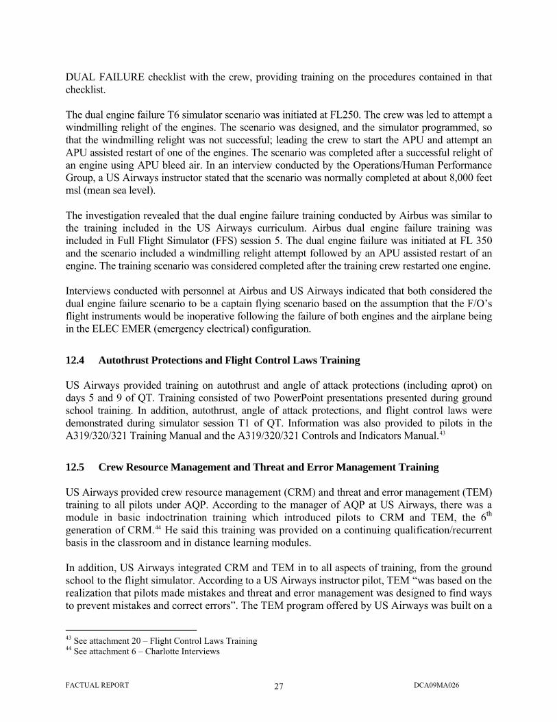
FACTUAL REPORT DCA09MA026 27
DUAL FAILURE checklist with the crew, providing training on the procedures contained in that checklist. The dual engine failure T6 simulator scenario was initiated at FL250. The crew was led to attempt a windmilling relight of the engines. The scenario was designed, and the simulator programmed, so that the windmilling relight was not successful; leading the crew to start the APU and attempt an APU assisted restart of one of the engines. The scenario was completed after a successful relight of an engine using APU bleed air. In an interview conducted by the Operations/Human Performance Group, a US Airways instructor stated that the scenario was normally completed at about 8,000 feet msl (mean sea level). The investigation revealed that the dual engine failure training conducted by Airbus was similar to the training included in the US Airways curriculum. Airbus dual engine failure training was included in Full Flight Simulator (FFS) session 5. The dual engine failure was initiated at FL 350 and the scenario included a windmilling relight attempt followed by an APU assisted restart of an engine. The training scenario was considered completed after the training crew restarted one engine. Interviews conducted with personnel at Airbus and US Airways indicated that both considered the dual engine failure scenario to be a captain flying scenario based on the assumption that the F/O’s flight instruments would be inoperative following the failure of both engines and the airplane being in the ELEC EMER (emergency electrical) configuration.
12.4 Autothrust Protections and Flight Control Laws Training US Airways provided training on autothrust and angle of attack protections (including αprot) on days 5 and 9 of QT. Training consisted of two PowerPoint presentations presented during ground school training. In addition, autothrust, angle of attack protections, and flight control laws were demonstrated during simulator session T1 of QT. Information was also provided to pilots in the A319/320/321 Training Manual and the A319/320/321 Controls and Indicators Manual.43
12.5 Crew Resource Management and Threat and Error Management Training US Airways provided crew resource management (CRM) and threat and error management (TEM) training to all pilots under AQP. According to the manager of AQP at US Airways, there was a module in basic indoctrination training which introduced pilots to CRM and TEM, the 6th generation of CRM.44 He said this training was provided on a continuing qualification/recurrent basis in the classroom and in distance learning modules. In addition, US Airways integrated CRM and TEM in to all aspects of training, from the ground school to the flight simulator. According to a US Airways instructor pilot, TEM “was based on the realization that pilots made mistakes and threat and error management was designed to find ways to prevent mistakes and correct errors”. The TEM program offered by US Airways was built on a
43 See attachment 20 – Flight Control Laws Training 44 See attachment 6 – Charlotte Interviews

FACTUAL REPORT DCA09MA026 28
concept of three colors (red, yellow and green) or situation awareness markers that allowed pilots to say; “I’m no longer in the green”.45 Instructors worked with pilots to help them identify where they were with their situation awareness and task loading (the number of tasks to be completed divided by the amount of time available to complete them). TEM at US Airways also focused on the ABCs - Assess what the situation is and/or threats are, Balance available barriers using policies, procedures and flows, checklists, automation, external resources, human factors, and knowledge of aircraft handling, Communicate effectively and understand callouts, and Standard operating procedures. Posters in classrooms and briefing rooms depict TEM and are encouraged for use during debriefings. According to the Airbus fleet captain, “debriefing was the most valuable portion of the training to make sure the pilots walked away with even higher levels of understanding and hopefully, correlation”.
Instructor pilots focused on TEM during simulator sessions T7-T9. At the completion of an event, the crew’s TEM was rated on a scale of 1 to 5 (1 = unsatisfactory, 5 = no errors). Session T9 was a Line Oriented Flight Training (LOFT) scenario that included two legs of flying and special airport training. At the completion of T9, a crew would be signed off for the Line Oriented Evaluation (LOE), the qualification check where pilots demonstrate their proficiency and get their type rating.
12.6 Training Program Evaluation The US Airways Manager of AQP stated that the evaluation of the AQP training program included a continual review of information collected from integrated data sources and an annual review by an extended review team. The extended review team met each year in July and included members from US Airways, FAA AFS-230, and the US Airways Certificate Management Office. US Airways prepared a presentation for this meeting each year to provide an overview of data collected, highlight significant events, and to discuss any recommended changes. 13.0 Additional Information
13.1 Abnormal and Emergency Situations A National Aeronautics and Space Administration (NASA) report published in June 2005 discussed the challenges of emergency and abnormal situations in aviation.46 The report highlights that “some situations may be so dire and time-critical or may unfold so quickly” that pilots must focus all of their efforts on the basics of aviation – flying and landing the airplane – with little time to consult emergency checklists. Although pilots are trained for emergency and abnormal situations, it is not possible to train for all possible contingencies. Furthermore, while training under AQP
45 See attachment 21 – TEM Training 46 B.K. Burian, I. Barshi, and K. Dismukes. The Challenge of Aviation Emergency and Abnormal Situations, NASA Technical Memorandum 2005-213462 (Moffett Field, California: National Aeronautics and Space Administration, 2005).

FACTUAL REPORT DCA09MA026 29
provides operators with greater flexibility than guidance provided under FAR Part 121 appendix H, operators are faced with time and financial constraints limiting the “range and depth” of the emergencies trained to those that are most common and for which the checklist procedures work as expected. Also limited is the ability of the simulations to replicate real world emergency and abnormal situations and demands. The report, however, stresses that training for these situations do benefit pilots and a review of voluntary reports filed on the Aviation Safety Reporting System (ASRS) indicated that over 86 percent of “textbook emergencies” (i.e., those in which a good checklist exists) were handled well by flight crews. Unfortunately only about seven percent of non-textbook emergencies were handled well by flight crews. One reason for this is that human capabilities are limited. One study found that underlying errors made in response to emergency and abnormal situations were the result of normal cognitive limitations experienced by humans when faced with stress, concurrent task demands, and time pressure.47 This can in turn lead to distractions from cockpit duties.48 The reason for this is that identifying the problem and selecting the appropriate procedure requires extensive attention from the flight crew. In addition, because flight crews have limited opportunities to practice abnormal situations, performing the appropriate procedures requires greater effort and concentration. Finally, abnormal or emergency situations lead to flight crews narrowing their attention and becoming cognitively rigid, which can reduce the crew’s ability to analyze and resolve the situation.
13.1.1 Ditching Reviews in the Literature The US Department of Transportation (DOT) report “Transport Water Impact and Ditching Performance,”49 dated 1996, stated that between 1959 and 1991, there were 1 planned (ditching50) and 13 unplanned water landings51 worldwide by transport category aircraft. Similar findings were presented in the FAA report, “Study on Transport Airplane Unplanned Water Contact.”52 From the review, the DOT report concluded that a majority of water related mishaps occur during takeoff, approach and landing, when an airplane is in close proximity to the airport. It was also found that most water related accidents result in fuselage separation and/or crush, to some degree, which could impact passenger safety and evacuation.
47 R.K. Dismukes, B.A. Berman, and L. Loukopoulos, The Limits of Expertise: Rethinking Pilot Error and The Causes of Airline Accidents, (Aldershot, United Kingdom: Ashgate Publishing Company, 2007). 48 K. Dismukes, G. Young, and R. Sumwalt, “Cockpit Interruptions and Distractions,” ASRS Directline, vol. 10 (1998), pp. 4-9. 49 A.A. Patel and R.P. Greenwood, Jr., Transport Water Impact and Ditching Performance, DOT/FAA/AR-95/54 (Washington, DC: Department of Transportation, 1996). 50 “Ditching” refers to a landing as the result of planned water contact in which the touchdown rate must be ≥ 5 feet/second and the longitudinal and vertical loads are within the design parameters of the aircraft. Occupants also have several minutes of preparation time prior to impact and injuries are less severe. 51 “Unplanned water landings” refers to a landing in which aircraft velocities, forces and damage are high. In addition, occupants have minimal, if any, time to prepare, and injuries are severe. 52 R. Johnson, Study on Transport Airplane Unplanned Water Contact, DOT/FAA/CT/84-3 (1984).

FACTUAL REPORT DCA09MA026 30
A review of US civil aircraft operating between 1979 and 1983 revealed 214 ditchings.53 Of these, 16 percent resulted in fatalities. Furthermore, 63 percent of ditchings occurred during non-overwater operations. A document published by the US Coast Guard states that for ditchings that occur when no power is available, the approach speed used should be greater than normal down to the flare.54 It continues that this will provide the pilot with a speed margin to break the glide earlier and more gradually, thus allowing the pilot time and distance to “feel for the surface.” It is also stated that when no power is available to the airplane, using flaps may result in the airplane flying at a lower nose attitude and descending more steeply, and flaps may also make it more difficult for the pilot to judge the flare.55 The author notes that the benefits achieved when using flaps, such as a lower stall speed, should be weighed against the challenges associated with using flaps.
13.2 Flight Crew Coordination Coordination involves the ability of crewmembers to incorporate and synchronize the tasks required of them in a correct and timely manner,56 and requires optimal effort from all crewmembers in order to work effectively. When crews share an understanding of the tasks (what they are and how to accomplish them), research indicates that this leads to improved and more efficient communication, which is critical during periods of high workload.57 The accident captain was asked to describe the crew coordination between him and the F/O during the accident event. The captain said it was amazingly good considering how suddenly the event occurred, how severe it was, and the little time they had. The captain said he did not have time to exchange words but through observations of the event and hearing the F/O say things, the captain knew that the F/O knew what he had to do. The captain was immediately aware that he and the F/O were on the same page and the F/O was doing his part. The F/O made similar statements indicating that he and the captain each had specific roles and knew what each other was doing and they interacted when they needed to. The captain credited the CRM training provided at US Airways that gave them the skills and tools that they needed to build a team quickly and open lines of communication, share common goals and work together.
13.3 Naturalistic Decision Making Naturalistic decision making refers to how people make decisions, using their expertise and prior experiences, in real-world settings.58 The recognition-primed decision making (RPD) model is a
53 R.L. Newman, “A Case History and Review of the Record,” SAFE Journal, vol. 18, no. 1 (1988), pp. 6-15. 54 “Aircraft Emergency Procedures Over Water,” USCG CG-306; USAF AFM-64-6; Army FM- 20-151; USN OPNAV INST 3730.4A, November 1968 55 Newman, 1988 56 J.A. Cannon-Bowers, S.I. Tannenbaum, E. Salas, and C.E. Volpe, “Defining Team Competencies and Establishing Team Training Requirements,” in R. Guzzo, E. Salas, & Associates, eds., Team Effectiveness and Decision Making in Organizations (San Francisco: Jossey-Bass, 1995), pp. 333-380. 57 R.J. Stout, J.A. Cannon-Bowers, E. Salas, and D.M. Milanovich, “Planning, Shared Mental Models, and Coordinated Performance: An Empirical Link is Established,” Human Factors, vol. 41, no. 1 (1999), pp. 61-71. 58 C.E. Zsambok, “Naturalistic Decision Making: Where Are We Now?,” in C.E. Zsambok and G.A. Klein, eds.,

FACTUAL REPORT DCA09MA026 31
technique used by experts to come rapid decision when faced with complex situations.59 To help them make decisions, experts proceed through the RPD process: (1) cues in the environment are identified to help them recognize patterns, (2) patterns activate action scripts from memory of past similar experiences, (3) action scripts are assessed through mental simulation (playing through ‘what if’ scenarios), and (4) a decision made and executed based on the best available options. RPD reveals a critical difference between experts and novices when presented with recurring situations.60 Experts in general will make quicker decision because the situation may match a prototypical situation they have encountered before. Novices, lacking this experience, must cycle through different possibilities, and tend to use the first course of action that they believe will work. The inexperienced also have the tendencies of using trial and error through their imagination. Interviews with the flight crew focused on decisions made during the accident sequence (see also section 13.4 “Landing Strategy”). For example, when asked about his decision to use flaps 2 versus flaps 3 as called for in the ENG DUAL FAILURE checklist, the captain stated that there were operational advantages to using flaps 2 that became obvious to him. He was concerned about having enough energy remaining to successfully flare the airplane and reduce the rate of descent sufficiently for landing. He knew that going to flaps 3 would not give him much more of an advantage in terms of lowering the stall speed, and drag would have increased. From his experience, flaps 2 would give him a slightly higher nose attitude when landing, but felt that in the accident situation, flaps 2 was the optimum setting.
13.4 Checklist and Procedure Design for Emergency and Abnormal Situations Researchers at NASA have studied the implications of emergency/abnormal situations in aviation on checklist and procedure design.61 While it is noted that it is not possible to develop a checklist and procedure for all possible contingencies, the report highlights the importance of having emergency/abnormal situation checklists or procedures for “for all phases of flight in which they might be needed”. Furthermore, emergency/abnormal checklists and procedures must include the necessary information and steps to respond appropriately.62 The report states that when designing for emergency/abnormal situations, attention should be paid to the wording, organization and structure of the checklist and procedures to make sure they are easy to use, clear, and complete for flight crews. As attention narrows during emergency/abnormal situations due to increased workload and stress, checklists and procedures should minimize the memory load on flight crews, and some airlines and manufacturers are reported to have reduced the number of memory items that flight crews are required to memorize. Naturalistic Decision Making (Mahwah, NJ: Erlbaum, 1997), pp. 3-16. 59 G. Klein, Intuition at Work, (New York: Currency Doubleday, 2003). 60 E. Salas and G. Klein, eds., Linking Expertise and Naturalistic Decision Making, (Mahwah, NJ: Lawrence Erlbaum Associates, 2001). 61 Burian, Barshi, and Dismukes, pp. 8-11. 62 B.K. Burian, R.K. Dismukes, and I. Barshi, “The Emergency and Abnormal Situations: A Review of ASRS Reports”, in R. Jensen, ed., Proceedings of the 12th International Symposium on Aviation Psychology, (Dayton, OH: Wright State University Press, 2003).

FACTUAL REPORT DCA09MA026 32
Checklist developers face a dilemma of developing a checklist that is not cumbersome but that is also complete. Short checklists offer an increased likelihood that crews can complete all pertinent items related to the emergency or abnormal without distracting crews from other cockpit duties. However, accidents and incidents have shown that flight crews can become so fixated on the emergency/abnormal that routine items (e.g., configuring for landing) are overlooked. For this reason, emergency and abnormal checklists include reminders for flight crews of items that may be forgotten. Additionally, flight crews can lose their place in checklists if they are required to alternate between various checklists or are distracted by other cockpit duties, however, combining checklists can result in lengthy procedures that are difficult to follow.
13.5 Landing Strategy Ditching the airplane into the Hudson River was considered by the crew to be the safest option for a forced landing. The captain stated in his interview that based on the flight’s position, altitude, airspeed, heading away from the airport, and the amount of time it took to stabilize the airplane and analyze the situation, returning to LGA was not possible.63 The captain stated that returning to LGA would have been an “irrevocable choice” and if he had attempted to land there and realized that he could not, he would have had no other landing options. He stated that before he would make the decision to land on a runway, he would need to be sure that he could make it without landing short or long, he could line up the flight path with the runway, he could stay on the runway, and that he would have a sink rate that was survivable and would not collapse the landing gear and create a post crash fire. He stated that he could not afford to make the wrong decision and he was confident that he could make a successful water landing. The F/O stated in his interview that the crew discussed returning to LGA but it was far away at the decision making point and the airplane was coming down fast. Regarding attempting to land at TEB, the captain stated they were “too far away, too low and too slow” and the only other option that was long enough, smooth enough and wide enough was the Hudson River. The F/O stated that TEB did not look viable and appeared too far away. He said “if the image is rising in the windshield you aren't landing there” and the only other option was straight ahead down the river. 14.0 Procedures and Checklist Development Airbus had a Continuous Improvement Process within the Flight Operations Support & Services department that worked closely with the training department and had direct relations with the airlines.64 The Continuous Improvement Process received input from the flight crew training symposium, in-service difficulty reports and event reports and based on this information, Airbus would evaluate whether or not a change was needed to existing procedures. The typical process for a change was that a draft proposal would be sent to the training department for review, which sometimes included testing in a flight simulator. In the case of an
63 See attachment 1 – Flight Crew Interviews 64 See attachment 3 – Airbus VP Flight Operations Support and Services Interview

FACTUAL REPORT DCA09MA026 33
abnormal procedure, the procedure would be evaluated in the simulator by a training captain during the first stage of the proposal. The Airbus Flight Operations Support & Services department had 10 pilots in the department, four of whom were qualified as test pilots and who would conduct the simulator sessions. Following this, the proposal would proceed through a formal evaluation process with an operational evaluation panel consisting of personnel from the training department, flight department and flight safety personnel within Airbus. The evaluation panel would approve or disapprove requested changes and the vice president of Flight Operations Support & Services at Airbus would be in charge of the new procedure. Additional testing with a test pilot group would be conducted to determine that all steps in the procedure were written correctly before the change was implemented. Airbus would send details of the new procedures to the operators, publish the information on Airbus World, and communicate in meetings, conferences, and in the manual revision the reason for the change as well as a description of the change. After operators reviewed the procedures, they would present questions or comments that would be reviewed by Airbus. The new procedures would be used in training and Airbus received immediate feedback from the training department about the efficiency of the procedures. Airbus did not have direct access to operators’ documentation but they conducted 30-40 visits to operators each year. During the visits Airbus discussed with management, the documentation the operator used and how they incorporated the Airbus manuals in their programs. Airbus had no authority to make sure the operators used Airbus issued materials in their manuals, and it was up to the operator and the regulatory authority that approved the operators’ manuals. In 2004, Airbus made a change to the ENG DUAL FAILURE checklist procedure. The main improvement was to institute two parallel steps – one for a fuel remaining scenario and the other for a no fuel remaining scenario where no relight could be reattempted. In addition, the change included merging different procedures that were located in different locations in to one checklist. The ENG DUAL FAILURE checklist became a “stay in checklist” that could be used by crewmembers without the need for them to use other checklist procedures. These changes were made as a part of the Continuous Improvement Process at Airbus and were based on a review of accident reports in which crewmembers stated it was not easy to jump from one procedure to another. This change process took several months to complete and the new procedure became effective in 2005. Airbus made a 30 minute presentation in 2004 to operators regarding changes to the ENG DUAL FAILURE checklist procedure. The ENG DUAL FAILURE checklist was developed for the occurrence of a dual engine failure at high altitudes above 20,000 feet. According to Airbus, the ENG DUAL FAILURE checklist procedure was developed based on the highest probability in time of exposure that a dual engine failure would occur. The probability of a dual engine failure occurring at low altitude was very low and the discussion of a low altitude ENG DUAL FAILURE checklist was not specifically addressed.

FACTUAL REPORT DCA09MA026 34
15.0 FAA Oversight The FAA Certificate Management Office (CMO) for US Airways was located in Coraopolis, Pennsylvania. At the time of the accident, there was one aircrew program manager (APM) assigned to the US Airways Airbus fleet and one assistant APM who was in training.65 Interviews conducted with the APM indicated that there were five aviation safety inspectors (ASI) who assisted him with oversight of US Airways Airbus training and operations. Oversight activity included surveillance and observation of flight crew members, instructors, check airmen, and aircrew program designees (APD) in training, checking, and line operations. In addition, the APM stated that he was also assigned some Element Performance Inspections through the Air Transportation Oversight System (ATOS). The APM said that he spent the majority of his time overseeing the APD’s while the inspectors assisting him spent more time observing training activities. According to interviews, each inspector or APM conducted, on average, two or three surveillance activities per week at US Airways. The principle operations inspector (POI) for US Airways was stationed at the CMO in Coraopolis, PA. Interviews conducted with the POI66 indicated that there were also three assistant POI’s assigned to the US Airways certificate. US Airways and America West Airlines had merged a few years prior and all oversight was then managed from the CMO in Pennsylvania. The POI said that he did not normally conduct surveillance activities himself but had oversight of the APM’s and operational programs for each fleet at US Airways. The POI stated that he had daily interaction with the APM’s. The POI was responsible for the approval of amendments to training and operational procedures manuals at US Airways. The POI stated that he required a review and recommendation by the APM’s prior to approving any amendments. In addition, any airplane specific procedures were compared to the manufacturer’s recommended procedures, and changes to non-normal procedures were coordinated with the certification office before approval. US Airways conducted training under the AQP and any change to the training program or training manuals was coordinated with FAA AFS-230 before approval was granted.
Submitted by: ______________________ David Helson Katherine Wilson Air Safety Investigator, Operations Human Performance Investigator May 15, 2009
65 See attachment 4 – APM and POI Interviews 66 See attachment 4 – APM and POI Interviews

1
NATIONAL TRANSPORTATION SAFETY BOARD Office of Aviation Safety Washington, D.C. 20594
May 7, 2009
Systems Group Chairman’s Factual Report
DCA-09-MA-026
A. ACCIDENT
Operator: US Airways Location: Hudson River Date: January 15, 2009 Time: 1530 Eastern Standard Time Airplane: Airbus Industrie A320-214, N106US
B. SYSTEMS GROUP
Chairman: Scott Warren National Transportation Safety Board Washington, D.C. Member: Arnaud Desjardin Bureau d’Enquetes et d’Analyse pour la sécurité de l’Aviation Civile Aeroport du Bourget, France Member: Andrew Hiller US Airways Phoenix, AZ Member: Scott Orloff International Association of Machinists Charlotte, NC Member: Pete Dolf US Airline Pilots Association Charlotte, NC Member: Christophe Duphil Airbus SAS Blagnac, France

2
C. SUMMARY
On January 15, 2009, about 1527 Eastern Standard Time, US Airways flight 1549, an Airbus A320-214, registration N106US, suffered bird ingestion into both engines, lost engine thrust, and landed in the Hudson River following take off from New York City's La Guardia Airport (LGA). The scheduled, domestic passenger flight, operated under the provisions of Title 14 CFR Part 121, was en route to Charlotte Douglas International Airport (CLT) in Charlotte, North Carolina. The 150 passengers and 5 crewmembers evacuated the aircraft successfully. One flight attendant and four passengers were seriously injured.
The Systems Group convened on January 15-20, 2009 in New York City, NY, to
examine and document the aircraft. D. DETAILS OF THE INVESTIGATION
1.0 Flight Controls
The pitch trim system was examined, and the trim indications were noted from the indicating wheel in the cockpit, the index marks on the tail, and by measuring the trimmable horizontal stabilizer actuator (THSA). The pitch trim wheel in the cockpit indicated approximately 4.7 units aircraft nose up. The index marks on the tail indicated a position of 4.7 units aircraft nose up. The measurements of the THSA were 270 mm measured from the bottom of the ball screwjack to the top of the lower ballscrew stop (measurement X’ on figure 1). The length of the upper screw section of the THSA (measurement X on figure 1) could not be measured accurately, but was determined to be approximately 270 +/- 40 mm. According to Airbus documentation, these measurements correlated to a pitch trim position between 4.5 and 5 units aircraft nose up.

3
Figure 1
Trimmable Horizontal Stabilizer Actuator Measurement Locations The left wing was examined, and an inboard section of the outboard flap was missing. The left inboard flap was badly damaged, while the remainder of the left outboard flap appeared to be only slightly damaged. The right wing was examined, and all sections of the flaps were present, but both the inboard and outboard flaps were bent out of their normal shape. The flap positions were determined by taking measurements as specified in figure 2. The measurements are taken along the flap track beam between the flat of the “full retract” stop and the edge of the side roller of the flap carriage (measurement X on figure 2). These measurements were taken on tracks 2 and 3 of the right wing and were determined to be 358 and 361 mm respectively. According to Airbus documentation, these measurements correspond with flap position 2. Examination of the flap lever in the cockpit determined that the lever was in position 2. These measurements could not be taken on the left wing because these measurement points were not accessible. Qualitative examination determined that the flap positions on each side of the aircraft appeared to be the same.
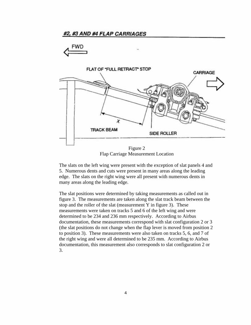
4
Figure 2
Flap Carriage Measurement Location The slats on the left wing were present with the exception of slat panels 4 and 5. Numerous dents and cuts were present in many areas along the leading edge. The slats on the right wing were all present with numerous dents in many areas along the leading edge. The slat positions were determined by taking measurements as called out in figure 3. The measurements are taken along the slat track beam between the stop and the roller of the slat (measurement Y in figure 3). These measurements were taken on tracks 5 and 6 of the left wing and were determined to be 234 and 236 mm respectively. According to Airbus documentation, these measurements correspond with slat configuration 2 or 3 (the slat positions do not change when the flap lever is moved from position 2 to position 3). These measurements were also taken on tracks 5, 6, and 7 of the right wing and were all determined to be 235 mm. According to Airbus documentation, this measurement also corresponds to slat configuration 2 or 3.

5
Figure 3
Slat Position Measurement Locations
1.1 Observations Regarding Other Aircraft Systems Items
After examining the aircraft, the following items were noted (the damage noted in this report was identified after several boats impacted the aircraft during the recovery operations and the aircraft was lifted out of the water onto a barge): The outflow valve doors were separated from the outflow valve door actuator. A position for the outflow valve door could not be determined. The ram air turbine (RAT) was noted to be in the extended position when the aircraft was lifted from the water. Both blades on the RAT were present, and no major deformation of the blades could be seen. The RAT was substantially damaged when the aircraft was placed on the barge. The avionics cooling skin air inlet valve and skin air outlet valve were both found in the closed position. The blue hydraulic system reservoir was located in its normal location, and one of its return lines was severed. The indicated fluid level was empty.

6
The tailcone, including the APU was broken off of the fuselage of the aircraft, and it was hanging from the rear of aircraft by the APU generator cables. After the aircraft was lifted from the water and placed on the recovery barge, the following recording units and avionics boxes were removed from the aircraft: Cockpit Voice Recorder (CVR) Allied Signal P/N: 980-6020-001 S/N: 2878 Date Code: 9908 Mod: 1, 2, 4, 5, 6, 7, 8, 9 Flight Data Recorder (FDR) Honeywell P/N: 980-4700-003 S/N: 7336 Date Code: 0106 Mods: 1, 2, 3, 4, 5, 6, 7, 9, 10, 11, 12, 13, 15, 16, 17, 18 Enhanced Ground Proximity Warning System (EGPWS) Honeywell P/N: 965-10976-003-206 (mod 3)-206 (mod 2) S/N: 7393 Mfg date: 0010 Mod Status: 1-11 inclusive Data Management Unit (DMU) SFIM Industries P/N: ED45A300 S/N: 884 Date Code: 11/99 No Amendments
1.2 Cockpit Documentation
The cockpit switch and button positions were examined, and the following items were noted: CAPT/FO Instrument Panel PFD/ND’s - Each knob was in the full bright position Speakers - Off Console/Floor – Off A/Skid & N/W STRG – On

7
Landing Gear Lever – Up Yellow Pressure Brake Triple Indicator – All indicators at zero psi Glare shield Capt – Altimeter Units Selector: InHg, Navigational mode selector: Arc,
Navigational display range selector: 80nm, ADF/VOR selector: off F/O - Altimeter Units Selector: InHg, Navigational mode selector: Arc,
Navigational display range selector: 10nm, ADF/VOR selector: off Alt Selector – 100’ Pedestal Switching Panel: All selectors in the normal position ECAM upper/lower screens: All knobs in the full bright position Radio Management Panel (RMP) power switch Capt. & F/O: both on THS: 4.7 up Thrust Lever: L – Climb Detent, R- 1/8 inch aft of climb detent Capt Audio Control Panel (ACP): Com 1 button - out, volume - 10 o’clock
position. Interphone: out, volume - 2 o’clock position Main flood light – Off, Integral – full bright, pedestal flood – off Radar tilt: +5 degrees for both pilots, Capt - wx/turb position, windshear auto,
control on Capt. F/O- wx position Engine Masters – off Ignition – IGN/START F/O com - #1 button out, full loud volume Transponder: auto, #2, alt on, tcas all position, TA/RA selected Speedbrake handle in the retract position Flap handle in position 2 Parking brake: off Overhead panel: Adirs: Displayed Information Selector – TK/GS, Displayed System Selector -
SYS 3, System Mode Selectors - all in NAV Evac panel: Capt position FLT CTL: All in GPWS: Unknown position (pushbutton does not change position when
pushed, so the current state of the switch could not be determined) Recorder Panel: Unknown (pushbutton does not change position when
pushed, so the current state of the switch could not be determined) Oxygen Panel: Unknown (pushbutton does not change position when pushed,
so the current state of the switch could not be determined) Wipers: Capt. & F/O: Off Fire Panel: Eng 1&2: out, APU: in, agent buttons: unknown (pushbutton does
not change position when pushed, so the current state of the switch could not be determined)

8
Hyd Panel: All buttons – in, except Elec pump Fuel Panel: Unknown (pushbutton does not change position when pushed, so
the current state of the switch could not be determined) Electrical Panel: Unknown (pushbutton does not change position when
pushed, so the current state of the switch could not be determined) Air Conditioning: Pack flow- norm, Heat knobs (Left to Right) -10 o’clock,
11 o’clock, 11 o’clock, All buttons - in except APU bleed, Xbleed - Auto Anti-ice: Wing button - out, engines and probe/window heat - unknown
(pushbutton does not change position when pushed, so the current state of the switch could not be determined)
Cabin Press: Ldg elev - auto, cabin mode sel and ditching - unknown (pushbutton does not change position when pushed, so the current state of the switch could not be determined)
Lights: Strobe - auto, beacon - on, wing - on, Nav & Logo - on, runway turnoff - off, land - on, nose - off
APU: Master Switch - in, start - unknown (pushbutton does not change position when pushed, so the current state of the switch could not be determined)
Internal lights: overhead integral - full bright, icing & Stby compass - off, dome - off, annunciator - bright
Seatbelt: off, no smoking - on Emerg exit: arm #3 ACP: com 1 and PA buttons out Flt Ctl panel above F/O: All in Cargo heat: All in, temp @ 4’oclock position Cargo smoke: unknown Ventilation: all in Eng man start: both out All O2 masks stowed, Capt & F/O rudder pedals full left Maintenance panel appears normal F/O sliding window outer pane cracked Circuit Breakers popped: #1 & #2 HP FUEL SOV (2 breakers), #1 & #2 ignition (1 breaker), FADEC A EIU #2, SEC #1 norm supply, ELAC #1 norm supply, slat/flap 1 position indicator, LGCIU #1, DMC #3 stby supply, DMC #1 supply, FWC #1 supply, SDAC 26 vac sync #2 ac essential bus, SDAC #1 supply,

9
CIDS director ess #1, CIDS director ess #2, MMR #1, VOR #1, F/O Flood, GEN #1 off, BTC #1 supply, eng 1 FADEC B& EIU #1, ECB supply
1.3 Electrical System Description
Two Integrated Drive Generators (IDG), one mounted on each engine, normally supply the aircraft electrical power in flight. These IDG’s supply electrical power which is then distributed throughout the aircraft by electrical busses. An IDG will only supply electrical power when the engine core speed (N2) is high enough for the generator to work properly. The IDG is disconnected if N2 is lower than 54%. The auxiliary power unit (APU) drives a third (auxiliary) generator (APU GEN), which can replace the electrical power normally supplied by either main generator (GEN 1 or GEN 2). Each of these 3 generators can supply the AC BUS 1, AC ESS BUS and AC BUS 2. An electrical schematic is attached as figure 4. The ram air turbine (RAT) is in a compartment in the left belly fairing, forward of the main landing-gear compartment. It extends automatically when there is a total failure of AC busbars 1XP and 2XP. The crew can operate it from the flight compartment if necessary. The RAT supplies hydraulic power to the Blue hydraulic system. If there is an electrical failure, the RAT also supplies the controlled speed motor generator (CSM/G) which gives electrical power to the aircraft. The RAT actuator allows for the deployment and retraction of the RAT. For the RAT retraction, the RAT actuator is hydraulically supplied. During the retraction sequence, a spring is compressed, and the RAT moves from the fully deployed position to the completely retracted (locked) position. The RAT retraction is initiated from the RAT stow panel located on the fuselage (there is no way to stow the RAT from the cockpit). For the RAT extension, or if for any reason the retraction sequence is aborted, the RAT is designed to deploy to its fully extended (locked) position. The extension power is provided by the spring force. The RAT is designed such that it is never supposed to be in an intermediate position except during RAT
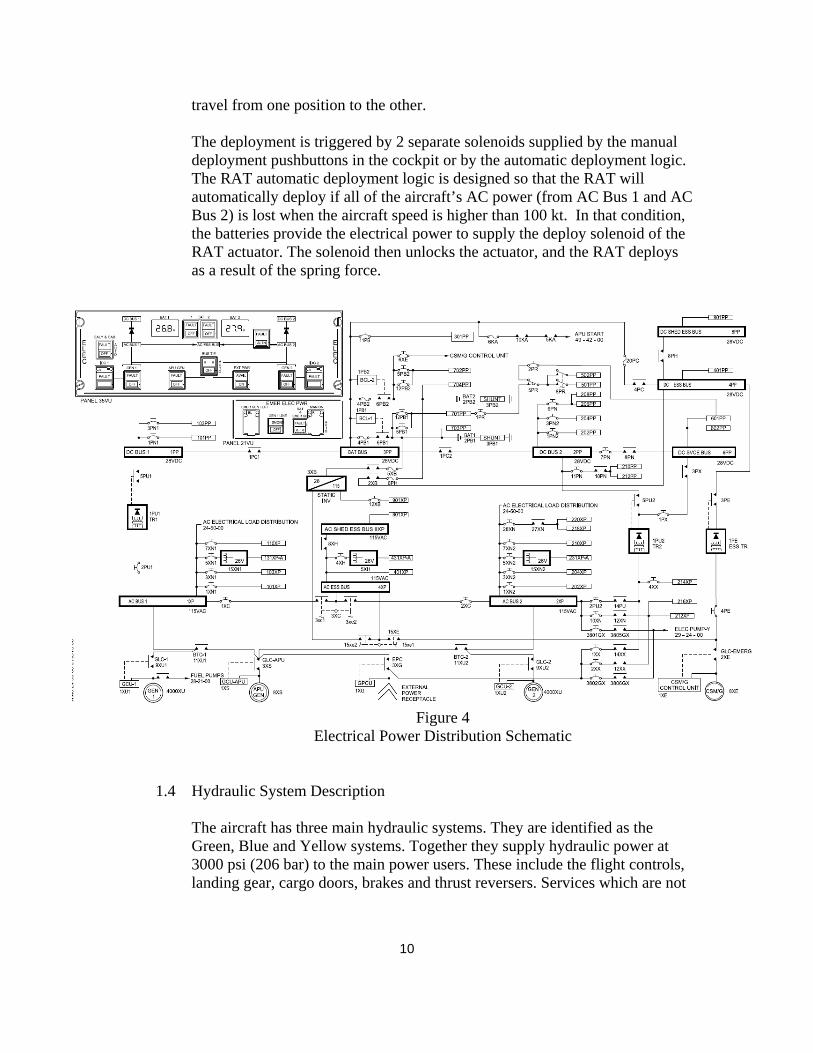
10
travel from one position to the other. The deployment is triggered by 2 separate solenoids supplied by the manual deployment pushbuttons in the cockpit or by the automatic deployment logic. The RAT automatic deployment logic is designed so that the RAT will automatically deploy if all of the aircraft’s AC power (from AC Bus 1 and AC Bus 2) is lost when the aircraft speed is higher than 100 kt. In that condition, the batteries provide the electrical power to supply the deploy solenoid of the RAT actuator. The solenoid then unlocks the actuator, and the RAT deploys as a result of the spring force.
Figure 4 Electrical Power Distribution Schematic
1.4 Hydraulic System Description
The aircraft has three main hydraulic systems. They are identified as the Green, Blue and Yellow systems. Together they supply hydraulic power at 3000 psi (206 bar) to the main power users. These include the flight controls, landing gear, cargo doors, brakes and thrust reversers. Services which are not

11
used during flight (cargo doors, brakes, landing gear and nosewheel steering) are isolated from the main supply.
The three systems are not hydraulically connected. Where possible they are kept apart to minimize the effect of an engine or tire burst, or other damage. There are no hydraulic lines in the passenger cabin or flight compartment. The three systems are each pressurized by one main pump (see figure 5). The Green system pump is connected to the left engine and the Yellow system pump is connected to the right engine. The Green and Yellow pumps supply hydraulic power when their engine operates. The electric pump of the Blue system starts automatically when any one of the engines is operating. The three system main pumps are usually set to operate permanently. If necessary (because of a system fault, or for servicing), the pumps can be set to off from the flight compartment. Most of the components of the systems are in the three hydraulic compartments. The Green system components are in the main landing gear compartment. The Yellow system components are in the hydraulic compartment in the right belly fairing. The Blue system components are in the hydraulic compartment in the left belly fairing. The two hydraulic compartments (Blue and Yellow) are forward of the main landing-gear compartment. The power transfer unit (PTU) of the Green/Yellow system is in the main landing gear compartment. It can operate in two directions, Green to Yellow, or Yellow to Green. There is no hydraulic fluid transferred between the two hydraulic systems during PTU operation, and it is used to pressurize one system from another if required. The PTU operates automatically when there is a difference in pressure between the two systems of 500 psi (35 bar). The PTU is permanently available, but can be set to off from the flight compartment if necessary. There is a quick-release self-sealing coupling which isolates the PTU to stop one system pressurizing the other during servicing. The Yellow electric pump is in the Yellow hydraulic compartment. It supplies the Yellow main system with hydraulic power when necessary (failure of the engine or engine pump). It is set to on from the flight compartment. It also starts when the aircraft is on the ground and a selection is made to operate the cargo doors. The hand pump of the Yellow system is on the Yellow ground service panel. It is used to operate the cargo doors if no electric power is available. The engine driven hydraulic pumps are driven by the engine core (N2). These pumps are able to supply hydraulic pressure as long as the engine is

12
running, even if N2 is lower than 54%. As a general rule, the lower the N2 is, the lower the hydraulic flow that can be delivered by the engine driven hydraulic pumps.
Figure 5
Hydraulic System Schematic Scott Warren Lead Aerospace Engineer

Docket No. SA-532 Exhibit No. 16 A
National Transportation Safety Board
Washington, DC
Wildlife Factors Group Chairman Factual Report
(15 pages)

NATIONAL TRANSPORTATION SAFETY BOARD
OFFICE OF AVIATION SAFETY WASHINGTON, D.C.
May 15, 2009
Wildlife Factors Group Chairman’s Factual Report of Investigation
DCA09MA026

NATIONAL TRANSPORTATION SAFETY BOARD OFFICE OF AVIATION SAFETY
WASHINGTON, D.C.
May 15, 2009
Wildlife Factors Group Chairman’s Factual Report of Investigation
A. Accident : DCA09MA026 LOCATION : New York, NY DATE : January 15, 2009
TIME : ~ 1530 Eastern Standard Time AIRCRAFT : Airbus Industrie A320-214, N106US OPERATOR : US Airways, flight 1549
B. Airports Group
Chairman : Mark H. George National Transportation Safety Board Washington, D.C. Member : Michael J. Begier
United States Department of Agriculture, Animal and Plant Health Inspection Service, Wildlife Services
Washington, D.C.
Member : Allen Gosser United States Department of Agriculture, Animal and Plant Health Inspection Service, Wildlife Services
Castleton, NY Member : Evelyn Martinez
FAA Airports Division Jamaica, NY
Member : Doug Stearns
Port Authority of New York & New Jersey LaGuardia Airport Flushing, NY
1

C. Summary
On January 15, 2009, about 1530 Eastern Standard Time, U.S Airways flight 1549, an Airbus Industrie A320-214, registration N106US, lost thrust in both engines and made an emergency landing in the Hudson River, following take off from New York's LaGuardia Airport (LGA). The scheduled, domestic passenger flight, operated under the provisions of Title 14 CFR Part 121, was en route to Charlotte Douglas International Airport (CLT) in Charlotte, North Carolina. The 150 passengers and 5 crewmembers evacuated the aircraft and were rescued by local ferry operators and boaters in the immediate area. D. Details of the Investigation According to the airplane’s flight data recorder and primary radar data, the initiating event occurred at a distance of 4.3 miles from LaGuardia Airport at an altitude of 2,818 feet above ground level (AGL). 1.0 Airport LaGuardia Airport (Figure 1) is located on approximately 680 acres in Flushing, NY, on the East River, adjacent to both Flushing Bay and Bowery Bay. It is at sea level. Near the airport property are urban, residential, and commercial areas, and major roads and parkways. LGA is .5 miles from the College Point Marine Waste Transfer Facility, 1.1 miles from College Point Shore Front Park, 1.2 miles from Citi Field (Mets Stadium), and 3 miles from Manhattan. Rikers Island 1 is approximately 600 feet from the departure end of Runway 4 (Figure 2). LGA has two runways: Runway 04/22 (7,001 ft. x 150 ft.) and runway 13/31 (7,003 ft. x 150 ft.). Both are grooved, asphalt/concrete composition, with high-intensity runway edge lights, and centerline lights. The departure ends of runways 13 and 22 incorporate engineered materials arresting system (EMAS) overrun protection areas. The current Airport Master Record 5010 for LGA indicated a total of 397,280 operations were conducted in calendar year 2007, which included commercial, general, and military aviation. The Master Record also contained the following remark: “Flocks of birds on & invof (in the vicinity of) arpt (airport).” LGA is certificated under 14 CFR Part 139, and is inspected by the FAA for regulatory compliance annually. As a requirement of certification, LGA maintains an Airport Certification Manual (ACM), containing chapters that document various airport operations. One chapter, the Wildlife Hazard Management Plan (WHMP), addresses the airport’s efforts to minimize wildlife hazards on the airport. The LGA WHMP was developed by United States Department of Agriculture (USDA) Animal and Plant Health 1 NYC Department of Corrections Detention Facility
2
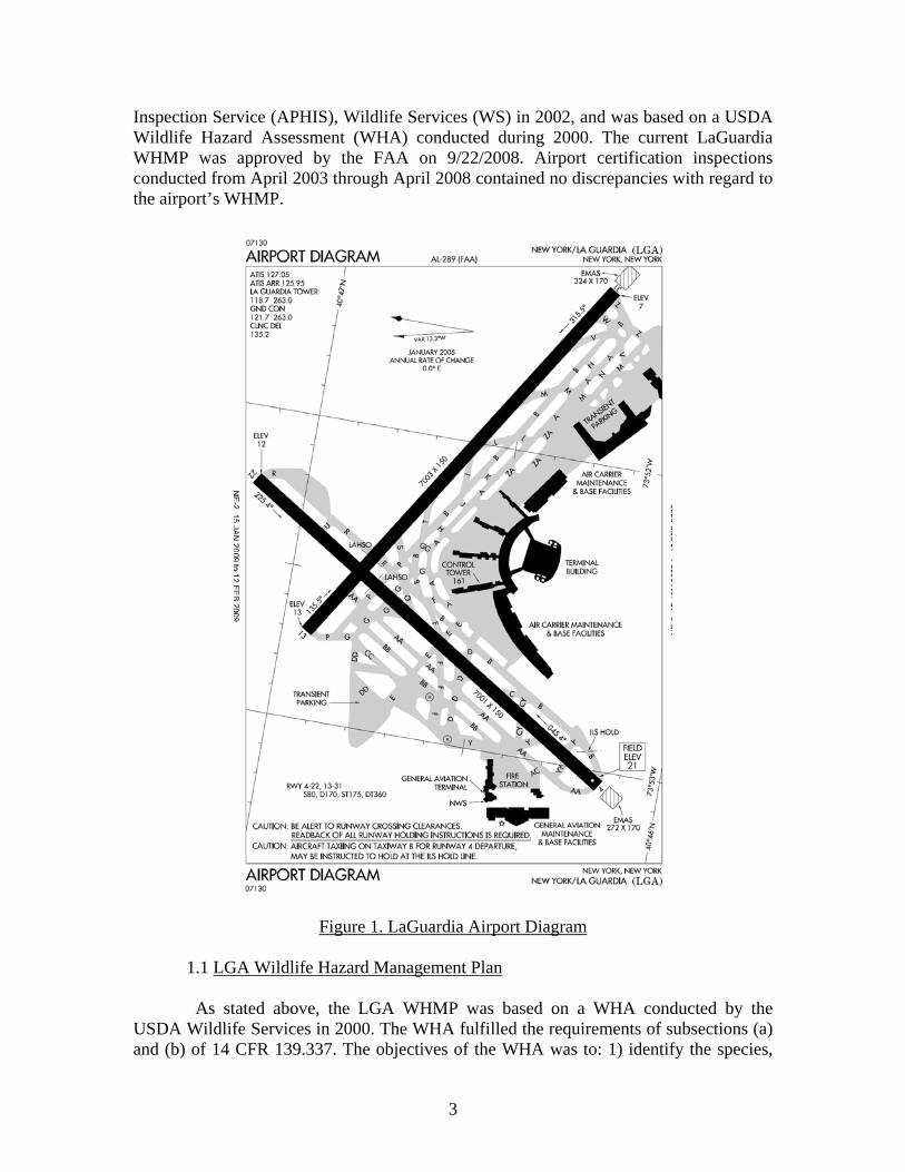
Inspection Service (APHIS), Wildlife Services (WS) in 2002, and was based on a USDA Wildlife Hazard Assessment (WHA) conducted during 2000. The current LaGuardia WHMP was approved by the FAA on 9/22/2008. Airport certification inspections conducted from April 2003 through April 2008 contained no discrepancies with regard to the airport’s WHMP.
Figure 1. LaGuardia Airport Diagram 1.1 LGA Wildlife Hazard Management Plan
As stated above, the LGA WHMP was based on a WHA conducted by the USDA Wildlife Services in 2000. The WHA fulfilled the requirements of subsections (a) and (b) of 14 CFR 139.337. The objectives of the WHA was to: 1) identify the species,
3

numbers, locations, local movement, and daily and seasonal occurrences of wildlife observed; 2) identify and locate features on and near the airport that attract wildlife; 3) describe existing wildlife hazards to air carrier operations; 4) review available wildlife strike records; and, 5) provide recommendations for reducing wildlife hazards at LGA. The resulting LGA WHMP fulfilled the requirements of subsection (f) of 14 CFR 139.337. In accordance with the WHA, LGA’s WHMP emphasizes the use of techniques to exclude, disperse, or remove hazardous wildlife from the airfield. These techniques include: active non-lethal and lethal means of removing birds, monthly wildlife surveys conducted by USDA Wildlife Services, development of an in-house enhanced gull removal program, and nest/egg mitigation. The WHMP notes that herring gulls, double-crested cormorants, and Canada geese pose serious strike threats to airplanes, due to their large size, and special emphasis is placed on removal of these species. In addition, USDA Wildlife Services assists with LGA wildlife mitigation activities, and also conducts an annual review of the airport's WHMP. Wildlife management personnel at LGA inspect the airfield for wildlife activity throughout each day, and monitor the tidal flat areas, especially the area adjacent to runway 31, looking for loafing and feeding birds. Any birds found on the airfield or using the flats are dispersed or removed, or when necessary, are destroyed. Wildlife management personnel assist the Port Authority Police Department in the capture and removal of stray mammals on the Airport Operations Area (AOA). LGA employs a full-time2 “bird supervisor” to perform wildlife control activities, maintain wildlife hazard management logs, recover and identify carcasses for wildlife strike reporting, and to gather and report other wildlife strike information. In addition, annual training of bird supervisors is conducted by qualified airport wildlife biologists. This training includes: wildlife identification, applicable laws, and wildlife management techniques. LGA, USDA, the City of New York, and other local, state and federal agencies are members of the NYC Wildlife Hazard Management Task Force, a group that was established to monitor and coordinate wildlife control activities at the airport, and throughout NYC. Among other activities, the task force works with landowners near the airport to minimize habitats and activities attractive to hazardous wildlife. Additional strategies used at LGA for wildlife mitigation are: Rikers Island Goose Population Management LGA and the USDA work together, along with the NYC Mayor's Office, NYC Department of Correction (which operates Rikers Island), the Town of Hempstead (Long Island, NY), NYC Department of Parks, NYC Department of Environmental Protection, NYC Economic Development Corporation, NY State Department of Environmental 2 A bird supervisor is on duty at LGA 24 hours a day, 365 days per year.
4
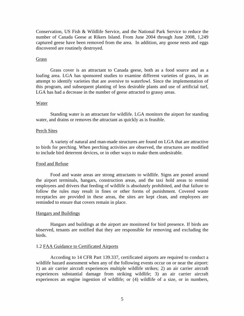
Conservation, US Fish & Wildlife Service, and the National Park Service to reduce the number of Canada Geese at Rikers Island. From June 2004 through June 2008, 1,249 captured geese have been removed from the area. In addition, any goose nests and eggs discovered are routinely destroyed. Grass Grass cover is an attractant to Canada geese, both as a food source and as a loafing area. LGA has sponsored studies to examine different varieties of grass, in an attempt to identify varieties that are aversive to waterfowl. Since the implementation of this program, and subsequent planting of less desirable plants and use of artificial turf, LGA has had a decrease in the number of geese attracted to grassy areas. Water Standing water is an attractant for wildlife. LGA monitors the airport for standing water, and drains or removes the attractant as quickly as is feasible.
Perch Sites A variety of natural and man-made structures are found on LGA that are attractive to birds for perching. When perching activities are observed, the structures are modified to include bird deterrent devices, or in other ways to make them undesirable. Food and Refuse Food and waste areas are strong attractants to wildlife. Signs are posted around the airport terminals, hangars, construction areas, and the taxi hold areas to remind employees and drivers that feeding of wildlife is absolutely prohibited, and that failure to follow the rules may result in fines or other forms of punishment. Covered waste receptacles are provided in these areas, the sites are kept clean, and employees are reminded to ensure that covers remain in place. Hangars and Buildings Hangars and buildings at the airport are monitored for bird presence. If birds are observed, tenants are notified that they are responsible for removing and excluding the birds. 1.2 FAA Guidance to Certificated Airports According to 14 CFR Part 139.337, certificated airports are required to conduct a wildlife hazard assessment when any of the following events occur on or near the airport: 1) an air carrier aircraft experiences multiple wildlife strikes; 2) an air carrier aircraft experiences substantial damage from striking wildlife; 3) an air carrier aircraft experiences an engine ingestion of wildlife; or (4) wildlife of a size, or in numbers,
5

capable of causing an event described above (1, 2, or 3) is observed to have access to any airport flight pattern or aircraft movement area. The regulation also requires that if the wildlife hazard assessment indicates that a wildlife hazard management plan is needed, the certificate holder, in consultation with the FAA Administrator, may decide that a wildlife hazard management plan is required and should be implemented. If this determination has been reached, the airport creates and implements a wildlife hazard management plan into their airport certification manual (ACM). The FAA provides guidance material in the form of Advisory Circulars (ACs), CertAlerts, and other documents (see section 2.3) for airports to use in constructing, implementing, and evaluating a wildlife hazard management plan.
Rikers Island
Figure 2. Aerial Photograph of LaGuardia Airport For certificated airports such as LGA, the FAA recommends that airport operators implement the standards and practices contained in Advisory Circular (AC) 150/5200-33B, Hazardous Wildlife Attractants on or near Airports. Section 1-4 of the AC, entitled, Protection of Approach, Departure, and Circling Airspace, recommends for all airports, a distance of 5 statute miles be established between the farthest edge of the Airport Operations Area (AOA) and any hazardous wildlife attractant, if the attractant could cause hazardous wildlife movement into or across the approach or departure airspace.
1.3 Airport Response
According to ATC transmissions, after flight 1549 departed LGA, the pilot radioed ATC, reported a “bird strike,” and indicated he was returning to the airport. ATC used the crash phone in the tower to alert aircraft rescue and firefighting (ARFF) crews of the returning airplane. A full ARFF response was initiated and fire trucks positioned
6

along the runway. In addition, a rescue boat was dispatched from LGA to the accident site.3 At 1537, Runway 04/22 and the adjacent safety areas were inspected by airport personnel and no FOD or wildlife remains were found. 2.0 FAA and USDA Wildlife Mitigation Efforts
2.1 FAA National Wildlife Strike Database Since 1990, the FAA has collected voluntary wildlife strike reports and maintained a wildlife strike database. The database is managed by Wildlife Services Program of the USDA APHIS under terms of an interagency agreement with FAA. Strike reports are sent to USDA Wildlife Services where they undergo a quality assurance process and are entered into the FAA strike database. Currently, the database contains 89,734 records of wildlife strikes to civil aviation (January 1990 - December 2008). The database can be used to identify species that are involved in strikes, seasonal patterns, and the extent and type of damage resulting from strikes. For the period of January 1, 2004 through December 31, 2008 the database strike information for LaGuardia Airport showed a total of 411 wildlife strikes, which involved all phases of flight. In 2005, USDA scientists completed a research project to determine what percentage of actual strikes was reported in the FAA database. The researchers obtained 14 independent sets of wildlife strike data from three airlines and three airports, for various years 1991 – 2004. By comparing the data from the airports and airlines with the data entered into the FAA wildlife strike database, it was determined that 21% of known strikes were actually captured in the database. These data indicate that the voluntary reporting system underestimates actual wildlife strikes, possibly missing as much as 80% of available data.4
2.2 Species Identification
The FAA maintains a contract with the Smithsonian Institute Feather Identification Laboratory for analysis and identification of bird remains found on airports. The results of the analysis are returned to the airport, the FAA, and the USDA Wildlife Services Program for addition to the National Wildlife Strike Database.
3 14 CFR Part 139 requires that certificated airports include in their emergency plans a water rescue plan if significant bodies of water and marsh lands are situated beneath the approach and departure paths within at least two miles of the end of the runway. 4 Wright, S. E. and R. A. Dolbeer. 2005. Percentage of wildlife strikes reported and species identified under a voluntary system. In Proceedings of Bird Strike Committee USA/Canada meeting, Vancouver, B.C. Canada (www.birdstrikecanada.com). The study is also documented in Cleary, E. C., R. A. Dolbeer, and S. E. Wright. 2005. Wildlife strikes to civil aircraft in the United States, 1990-2004. U.S. Department of Transportation, Federal Aviation Administration, Office of Airport Safety and Standards, Serial Report No. 11, Washington, DC. 53 pages.
7

2.3 Wildlife Hazards Manual Certificated airports have a responsibility under 14 CFR Part 139 to ensure the airport maintains a safe operating environment, including mitigation of wildlife hazards. To assist airports in managing these risks, the FAA and USDA collaborated to produce a manual entitled, Wildlife Hazard Management at Airports. The manual contains information to assist airport personnel in understanding and mitigating wildlife hazards to aviation , conducting WHAs, and in the development, implementation, and evaluation of WHMPs. The manual also includes specific information on the nature of wildlife strikes, legal authority, government agency roles and responsibilities, and pertinent regulations. The manual is available on the Internet at: http://wildlife.pr.erau.edu/EnglishManual/2005_FAA_Manual_complete.pdf 2.4 Wildlife Hazard Mitigation Research Programs
The FAA wildlife research program is conducted by the FAA Technical Center at Atlantic City, the USDA Wildlife Services National Wildlife Research Center Field Station in Sandusky, Ohio, and the University of Illinois Center of Excellence in Airport Technology. Some of the areas of research include: habitat modification, such as lengths and types of grass that attract or dispel birds, and harassment techniques such as air cannons, lasers, effigies, pulsed landing lights, falconry, and dogs. Other research studied airport vegetation, artificial turf, earthworm, rodent, and landfill control, and use of radar for bird detection. 2.5 Avian Radar A research project sponsored by the FAA and U.S. Navy Space and Naval Warfare Systems Center was initiated in 2000 to determine if low-cost, small mobile radars can reliably detect birds at or near airports, and if the results can be used to develop a local airport bird strike advisory system. Small, mobile radar evaluations are currently underway at Seattle-Tacoma International Airport, Naval Air Stations Whidbey Island and Patuxent River, Marine Corps Air Station Cherry Point, and Vancouver International Airport, Canada. Future research installations are planned for Chicago O’Hare International Airport, Dallas Fort Worth International Airport, and John F. Kennedy International Airport. According to the FAA website,5 from preliminary results of experimental avian radar systems, it is “not yet known if this system would be capable of providing alerts that would be operationally suitable for making specific decisions on landing or takeoff,” and that “research is continuing to address these operational type issues.” However, the FAA website indicates that radar data has shown to be useful in tracking and quantifying wildlife movements on and around airfields, as an enhancement to existing wildlife control programs.
5 http://www.faa.gov/news/fact_sheets/news_story.cfm?newsId=10376
8

2.6 Pulse Lights Reports that landing lights can be manipulated to repulse birds from the path of an airplane have existed in anecdotal form for many years; however, few systematic experiments have been conducted to assess the usefulness of such procedures. One such experiment, conducted by USDA,6 tested the hypothesis that during daylight, captive birds exposed to an approaching ground-based vehicle exhibiting pulsing 250-watt white aircraft landing lights would initiate avoidance behavior more quickly than birds experiencing an oncoming vehicle with non-pulsing (steady) or no lights (control). The experiment used captive brown-headed cowbirds (Molothrus ater), Canada geese (Branta canadensis), European starlings (Sturnis vulgaris), herring gulls (Larus argentatus), and mourning doves(Zenaida macroura) as subjects. The results showed 250-watt white landing lights, pulsed at 45 cycles/minute, influenced behavior of captive cow birds in response to an oncoming ground-based vehicle, however, the avoidance response was inconsistent across experiments, and little or no avoidance behavior was observed in other species. The researchers suggested that further research was needed to investigate avian response to specific light wavelengths and pulse frequencies. Another evaluation of pulsed landing lights was conducted by QANTAS Airlines in cooperation with a vendor of pulsed lighting systems. QANTAS outfitted five B737-400s and five B737-800s with the pulsed lighting systems, and then resumed normal operations for one year. The strike rates were then normalized and compared to strike data for comparable aircraft in the fleet that did not have pulsed lights installed. The results indicated that the average strike reduction rate between approximately 10% and 30% per 1,000 departures for B737-400 aircraft equipped with pulsed lights, and an average strike reduction rate between approximately 10% and 40% per 1,000 departures for B737-800 aircraft equipped with pulsed lights.7 3.0 Biological Material Sampling and Analysis On January 19, 2009, the Wildlife Factors Group examined various pieces of flotsam from flight 1549 stored in an FBI garage in New York City. Seven samples of unknown material were collected from wreckage from this site. Later that day, the group examined the fuselage and # 2 engine of flight 1549 on a barge in New Jersey. Samples of suspected biological material were collected from the right engine fan, the radome, the # 3 flap track on the left wing, and various locations on the fuselage. A total of ten samples were taken. On January 20, 2009, the shroud (“canoe”) from the # 3 flap track on the left wing was removed, and two additional samples were retrieved.
6 Bradley F. Blackwell and Glen E. Bernhardt, Efficacy of Aircraft Landing Lights in Stimulating Avoidance Behavior in Birds; Journal of Wildlife Management; Vol. 68, Issue 3; pp 725 – 732; July 2004. 7 Pulselite System B737 Operational Evaluation, Evaluation Period Jan 2005- August 2007, QANTAS, Unpublished.
9

On January 29, 2009, a USDA representative and General Electric (GE) personnel collected six samples from the exterior of the #1 engine, prior to engine teardown at the GE aircraft Engine Facility, Cincinnati, OH. On February 3 – 5, 2009, the USDA representative and the NTSB Powerplants Group, collected 23 samples of biological material (feathers, blood, muscle, and bone) from engine # 1, and 14 samples from engine # 2 . All samples were submitted to the Smithsonian Institution’s Feather Identification Laboratory for species identification. On February 16, 2009, the Feather Lab provided the results of the analyses. Of the 68 total samples received for identification, 39 were submitted for DNA testing. Of those, 18 (14 from engines) contained viable DNA and
Photograph 1. Investigators removing samples of biological material from engine # 2 fan. matched 99% or better to the Barcode of Life Database8 for Canada goose (Branta canadensis). A total of 52 (49 from engines) of the samples contained feathers or feather fragments that were consistent with Canada goose. Three of the samples from the fuselage contained microscopic feather fragments consistent with pigeon/dove, duck, and songbird (Passerines) (Attachment 1). 8 The Barcode of Life Database (BOLD) is an international collaborative effort to generate a unique genetic barcode for every species of life on earth
10

DNA sexing was successful on 16 of the 18 samples from the engines and wing of the aircraft. Both male and female Canada goose remains were found in engine #1; only male remains were found in engine #2; and only female remains were found on the left wing # 3 flap track.
Photograph 2: Feather remains found in the # 3 flap track assembly. The Smithsonian Institution also performed a stable-hydrogen isotope analysis9 of the feather material collected from the airplane engines, and then compared the results with feather samples collected from resident geese in the New York region. The results indicated that the feathers from the airplane engines were similar to samples of known migrant geese, and were significantly different from year-round resident populations from the New York region.10 Based on the findings, the likely subspecies of the geese remains were Branta canadensis canadensis or Branta canadensis interior (Figure 3). 9 Caccamise, Donald, F; L.M. Reed; P.M. Castelli; S. Wainright; T.C. Nichols, Distinguishing Migratory and Resident Canada Geese Using Stable Isotope Analysis; Journal of Wildlife Management, Vol. 64, No. 4, October 2000, pp. 1084-1091. 10 Marra, P. P., C. J. Dove, R. Dolbeer, N. F. Dahlan, M. Heacker, J. F. Whatton, N. E. Diggs, C. France, and G. A. Henkes. 2009 (in press). Migratory Canada Geese cause crash of US Airways Flight 1549, Frontiers in Ecology and the Environment.
11

Figure 3. Map of migratory routes for various subspecies of Canada geese 4.0 Wildlife Management Considerations Aircraft collisions with birds and other wildlife cost the civil aviation industry in the United States about $625 million per year.11 Approximately 98 percent of wildlife strikes involve birds (ibid). At least 229 people have died and 194 aircraft have been destroyed as a result of bird strikes and other wildlife strikes with civil and military aircraft from 1988 - April 2009.12 11 Dolbeer, R.A. and S. E. Wright. 2008. Wildlife strikes to civil aircraft in the United States, 1990-2007. U.S. Department of Transportation, Federal Aviation Administration, Serial Report No. 14. Washington, DC, USA. 57 pages. 12 Richardson, W. J., and T. West. 2000. Serious birdstrike accidents to military aircraft: updated list and summary. Pages 67-98 in Proceedings of 25th International Bird Strike Committee meeting. Amsterdam, The Netherlands; Thorpe, J. 2003. Fatalities and destroyed aircraft due to bird strikes, 1912-2002. Pages 85-113 in Proceedings of the 26th International Bird Strike Committee meeting (Volume 1). Warsaw, Poland. Dolbeer, RA, unpublished data.
12

The number of strikes annually reported in the US increased from 1,759 in 1990 to 7,666 in 2007.13 There are a number of reasons for the increase. Airports, with large areas of grass and pavement, are attractive habitats to birds for feeding and resting. Other wildlife such as deer and coyotes are also attracted to airport environments for similar reasons. Modern turbofan-powered aircraft have quieter engines, and are less obvious to birds, compared to noisier piston-powered aircraft and older turbine-powered aircraft. Additionally, commercial aircraft movements in the USA have increased at about 2% per year since 1980. The majority of wildlife strikes (93%) occur below 3,500 feet above ground level (AGL). Since 1960, 26 large-transport aircraft have been destroyed because of bird strikes worldwide, 24 (92%) of these strikes occurred during take-off or landing at less than 500 feet AGL.14 Various government-sponsored programs initiated over the past 40 years, such as pesticide regulation, expansion of wildlife refuge systems, wetlands restoration, and land-use changes, have resulted in increases in populations of many wildlife species in North America.15 Of the approximately 650 bird species that nest in North America, 36 have average body masses greater than 4 lbs. Of the 31 species for which population trend data are available, 24 (77%) showed population increases over the past 20-40 years, while two showed declines, and five were stable. Further, 13 of the 14 species with body masses over 8 lbs, such as the Canada goose, showed population increases. Canada goose populations in North America can be divided into two groups based on migratory behavior. One group continues to engage in annual seasonal migration, spending winter and summer months in different locations. The other group has ceased migratory behavior, therefore, establishes year-round residency in a particular location. Overall, the population of Canada geese has increased from 1.2 million in 1970 to 5.5 million in 2008. However, the largest portion of this increase has been within the population of resident geese which increased from .2 million in 1970 to 3.9 million in 2008. The migrant population has been relatively stable since 1990 with the population of about 1.6 million in 2008. In sum, resident geese comprised 19% of the total Canada geese in 1970, 39% of the total in 1990, and in 2008 accounted for 71% of the overall Canada goose population. Canada geese are particular hazardous to aviation due to their large size, flocking behavior, attraction to grazing sites at airports, and for the year-round presence of resident populations.16 13 Dolbeer, R.A. and S. E. Wright. 2008. Wildlife strikes to civil aircraft in the United States, 1990-2007. U.S. Department of Transportation, Federal Aviation Administration, Serial Report No. 14. Washington, DC, USA. 57 pages. 14 Dolbeer, R. A. 2006. Height distribution of birds recorded by collisions with aircraft. Journal of Wildlife Management 70 (5): 1345-1350. 15 Richard Dolbeer and Paul Eschenfelder. 2003. Amplified Birdstrike Risks Related to Population Increases of Large Birds in North America. Proceedings, International Bird Strike Committee 26, Volume I: 49-67. 16 Dolbeer, Richard A, and Seubert, John L.; Canada Goose Populations and Strikes With Civil Aircraft, 1990-2008: Challenging Trends for Aviation Industry, US Department of Agriculture, March 2009
13

Photograph 3, Canada goose (typical)
Table 1. Weights of Canada geese subspecies17 Branta canadensis canadensis Mean weight Maximum weight Male 3814 g (8.41 lbs) 6265 g (13.81 lbs) Female 3314 g (7.31 lbs) 5902 g (13.01 lbs) Branta canadensis interior Mean weight Maximum weight Male 4181 g (9.23 lbs) 4727 g (10.42 lbs) Female 3514 g (7.75 lbs) 3912 g (8.62 lbs) 4.1 New York City Metropolitan Area The four airports serving the NYC metropolitan area are JFK International Airport, LaGuardia Airport, Newark Liberty International Airport, Teterboro Airport, and Stewart International Airport. Three of these airports are located within a 10 mile radius of Manhattan. Numerous wildlife attractants exist in the vicinity of these airports, including: landfills, waste transfer stations, city parks, golf courses, ponds, roosting areas such as trees and shrubs, estuaries, tidal areas that expose food sources (e.g., shellfish), deep water areas that provide prey for diving birds like cormorants, roadway medians for nesting Canada geese, water detention basins, open dumpsters, recreational fields, grassland, and beaches. According to the FAA National Wildlife Strike Database, from January 1990 through August 2008, there have been a total of 4,253 bird strikes in the New York City area, including reports from JFK International Airport, LaGuardia Airport, Newark Liberty International Airport, and Teterboro Airport. In general, winter months (December, January, and February) have the fewest strikes in North America, whereas 17 CRC Handbook of Avian Body Masses, Dunning, John B., 2007.
14

15
the spring (May) and fall migration months (August, September, October) have the most strikes.18 These trends are consistent for the New York City area as well, where December, January, and February were the three consecutive months with the lowest number of strikes involving Canada geese, snow geese, and brant. Strike data for all wildlife species shows January as the month with the second fewest wildlife strikes, February has the fewest, and October has the most. Of the strike records that occurred in the New York City area from January 1990 through August 2008 (where altitude was reported), five percent occurred between 2,200 and 4,200 feet.19
5.0 Attachments 1. Smithsonian Institute Feather Lab Analysis
18 Dolbeer, R.A. and S. E. Wright. 2008. Wildlife strikes to civil aircraft in the United States, 1990-2007. U.S. Department of Transportation, Federal Aviation Administration, Serial Report No. 14. Washington, DC, USA. 57 pages. 19 FAA National Wildlife Strike Database.