-off-site dose calculation manual · -off-site dose calculation manual the off-site dose...
TRANSCRIPT

-OFF-SITE DOSE CALCULATION MANUAL
The Off-Site Dose Calculation Manual, PMP-6010-OSD-001, was revisedduring this reporting period. A copy of Revision 22 is included as part of thereport. The reasons for the changes and the PORC approval are documentedon the Review and Approval tracking form. These changes were determinedto maintain the level of radioactive effluent control required by 10 CFR20.1302, 40 CFR 190, 10 CFR 50.36a, and Appendix I to 10 CFR 50 and notadversely impact the accuracy or reliability of effluent, dose, or setpointcalculations.
A3.0-1

Document No.:Title:Alteration Category:CDI/50.59 No(s):
PMP-6010-OSD-001 Revision No.:OFF-SITE DOSE CALCULATION MANUALMinor RevisionN/A
022
PORC Mtg. No.: 4307CR No.:Superceding Procedure(s): N/A
Temporary Procedure Expiration Date:Temporary Change Expiration Date:Temporary Procedure/Change Ending Activity: N/AEffective Date: 14-Jun-2007 12:00:00 AM
ApprovalsName Review/Approval Type/Capacity DateWohlgamuth, Craig Cognizant Organization 16-May-2007 11:24:54 AMHershberger, Robert Programmatic-Other 21-May-2007 08:53:49 AMMutz, Brian Programmatic-Surveillance Section 21-May-2007 01:11:28 PMBeer, Joe Programmatic-ALARA 22-May-2007 03:48:17 PMWalker, David N Cross Discipline-BSP 24-May-2007 08:14:15 AMTurinetti, Dale Programmatic-Other 24-May-2007 12:40:16 PMHarner, Jon Technical Review 04-Jun-2007 10:39:00 AMNewmiller, Julie PORC I1-Jun-2007 12:10:49 PMMottl, Teri Approval Authority 12-Jun-2007 08:41:46 AM
Signature CommentsPROCEDURE APPROVAL AUTHORIZED BY L. WEBER, PLANT MANAGER. TLM
Document Number: PMP-6010-OSD-001 Revision: 022 Page 1 of I

ZAMERWIAM'POWER PMP-6010-OSD-001 Rev. 22 Page 1 of 91
OFF-SITE DOSE CALCULATION MANUAL
ReferenceDoug Foster Environmental Manager Environmental
Writer Document Owner Cognizant Organization
TABLE OF CONTENTS
1 PURPOSEAND SCOPE ........................................................................... 4
2 DEFINITIONS AND ABBREVIATIONS ...................................................... 4
3 DETAILS ................................................................................................ 6
3.1 Calculation of Off-Site Doses ............................................................ 6
3.1.1 Gaseous Effluent Releases ...................................................... 6
3.1.2 Liquid Effluent Releases ..................................................... 11
3.2 Limits of Operation and Surveillances of the Effluent Release Points ............. 14
3.2.1 Radioactive Liquid Effluent Monitoring Instrumentation ................ 14
3.2.2 Radioactive Gaseous Effluent Monitoring Instrumentation .............. 16
3.2.3 Liquid Effluents .................................................................... 17a. Concentration Excluding Releases via the Turbine Room Sump
(T R S) D ischarge ............................. : ................................ 17b. Concentration of Releases from the TRS Discharge .................... 17c . D o se ............................................................................ 18d. Liquid Radwaste Treatment System ..................................... 18
3.2.4 Gaseous Effluents .............................................................. 21a. D ose R ate ................................................................... 21b. Dose - Noble Gases ...................................................... 21c. Dose - Iodine-131, Iodine-133, Tritium, and Radioactive Material
in Particulate Form ........................................................... 22d. Gaseous Radwaste Treatment ........................................... 22
3.2.5 Radioactive Effluents - Total Dose ............................................. 25
3.3 Calculation of Alarm/Trip Setpoints ...................................................... 26
3.3.1 Liquid Monitors .................................................................... 27a. Liquid Batch Monitor Setpoint Methodology ......................... 27b. Liquid Continuous Monitor Setpoint Methodology ..................... 28
3.3.2 Gaseous Monitors .............................................................. 30a. Plant Unit Vent ............................................................ 30b. Waste Gas Storage Tanks ................................................ 33c. Containment Purge and Exhaust System .................................. 34d. Steam Jet Air Ejector System (SJAE) ..................................... 35e. Gland Seal Condenser Exhaust .......................................... 35

ZAMEDICANPOW .PMP-6010-OSD-001 Rev. 22 Page 2 of 91
OFF-SITE DOSE CALCULATION MANUAL
Reference
Doug Foster Environmental Manager EnvironmentalWriter Document Owner Cognizant Organization
3.4 Radioactive Effluents Total Dose ....................................................... 36
3.5 Radiological Environmental Monitoring Program (REMP) ...................... 36
3.5.1 Purpose of the REMP ........................................................ 36
3.5.2 Conduct of the REMP ............................................................ 37
3.5.3 Annual Land Use Census ..................................................... 39
3.5.4 Interlaboratory Comparison Program ........................ 40
3.6 Meteorological Model ........................................... 40
3.7 Reporting Requirements ................................................................. 41
3.7.1 Annual Radiological Environmental Operating Report (AREOR) ..... 41
3.7.2 Annual Radiological Effluent Release Report (ARERR) .................. 42
3.8 10 CFR 50.75 (g) Implementation ................................................... 43
3.9 Reporting/Management Review ........ ... ....... .............................. 44
FINAL CONDITIONS .......................................................................... 44
REFERENCES ..................................................................................... 44
4
5
Attachment 3.1
Attachment 3.2
Attachment 3.3
Attachment 3.4
Attachment 3.5
Attachment 3.6
Attachment 3.7
Attachment 3.8
SUPPLEMENTS
Dose Factors for Various Pathways .............................................. Pages 48 - 51
Radioactive Liquid Effluent Monitoring Instruments ................... Pages 52 - 54
Radioactive Liquid Effluent Monitoring InstrumentationSurveillance Requirem ents ............................................................ Pages 55 - 56
Radioactive Gaseous Effluent Monitoring Instrumentation .......... Pages 57 - 59
Radioactive Gaseous Effluent Monitoring InstrumentationSurveillance Requirem ents ............................................................ Pages 60 - 61
Radioactive Liquid Waste Sampling and Analysis Program ........ Pages 62 - 63
Radioactive Gaseous Waste Sampling and Analysis Program ..... Pages 64 - 65
Multiple Release Point Factors for Release Points ................................ Page 66

*AMMRIAM*POELRIC PMP-6010-OSD-001 Rev. 22 Page 3 of 91
OFF-SITE DOSE CALCULATION MANUAL
ReferenceDoug Foster Environmental Manager Environmental
Writer Document Owner Cognizant Organization
Attachment 3.9
Attachment 3.10
Attachment 3.11
Attachment 3.12
Attachment 3.13
Attachment 3.14
Attachment 3.15
Attachment 3.16
Attachment 3.17
Attachment 3.18
Attachment 3.19
Attachment 3.20
Attachment 3.21
Attachment 3.22
Attachment 3.23
Attachment 3.24
Liquid Effl uent Release Systems ........................................................... Page 67
Plant Liquid Effl uent Param eters ........................................................... Page 68
Volumetric Detection Efficiencies for Principle GammaEmitting Radionuclides for Eberline Liquid Monitors ........................... Page 69
Counting Efficiency Curves for R-19, and R-24 ........................... Pages 70 - 71
Counting Efficiency Curve for R-20, and R-28 ..................................... Page 72
Gaseous Effluent Release Systems ...................... Page 73
Plant Gaseous Effl uent Parameters ............................... ..................... Page 74
10 Year Average of 1995-2004 Data ................... ........................ Pages 75 - 76
Annual Evaluation of x/Q and D/Q Values For All Sectors ................. Page 77
D ose F actors .......................................................... ..................... P ages 78 - 79 .
Radiological Environmental Monitoring Program SampleStations, Sample Types, Sample Frequencies ............................... Pages 80 - 83
Maximum Values for Lower Limits of DetectionsAB - REMP ..... Pages 84 - 85
Reporting Levels for Radioactivity Concentrations inEnvironmental Samples .................................. Page 86
On-Site M onitoring Location - REM P .................................................. Page 87
Off-Site Monitoring Locations - REMP ...................... Page 88
Safety Evaluation By The Office Of Nuclear ReactorR egu lation ...................................................................................... P ages 89 - 9 1

Reference PMP-6010-OSD-001 Rev. 22 Page 4 of 91
OFF-SITE DOSE CALCULATION MANUAL
PURPOSE AND SCOPE
NOTE: This is an Administrative procedure and only the appropriate sections need beperformed per PMP-2010-PRC-003, step 3.2.7.
The Off-Site Dose Calculation Manual (ODCM) is the top tier document forthe Radiological Environmental Monitoring Program (REMP), theRadioactive Effluent Controls Program (RECP), contains criteria pertainingto the previous Radiological Effluent Technical Specifications (RETS) asdefined in NUREG-0472, and fully implements the requirements ofTechnical Specification 5.5.3, Radioactive Effluent Controls Program.
The ODCM contains the methodology and parameters to be used in the calculationof off-site doses due to radioactive liquid and gaseous effluents and in thecalculation of liquid and gaseous monitoring instrumentation alarm/trip setpoints.
The ODCM provides flow diagrams detailing the treatment path and the majorcomponents of the radioactive liquid and gaseous waste management systems.
The ODCM presents maps of the sample locations and the meteorologicalmodel used to estimate the atmospheric dispersion and deposition parameters.
The ODCM specifically addresses the design characteristics of the DonaldC. Cook Nuclear Plant based on the flow diagrams contained on the "OPDrawings" and plant "System Description" documents.
2 DEFINITIONS AND ABBREVIATIONS
Term: Meaning:S or shiftly At least once per 12 hoursD or daily At least once per 24 hoursW or weekly At least once per 7 daysM or monthly At least once per 31 daysQ or quarterly At least once per 92 daysSA or semi-annually At least once per 184 daysR At least once per 549 days.S/U Prior to each reactor startupP Completed prior to each releaseB At least once per 24 monthsSampling evolution Process of changing filters or obtaining grab samples
Reference PMP-6010-OSD-001 I Rev. 22 Page 5 of 91
OFF-SITE DOSE CALCULATION MANUAL
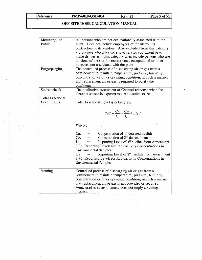
Member(s) ofPublic
All persons who are not occupationally associated with theplant. Does not include employees of the utility, itscontractors or its vendors. Also excluded from this categoryare persons who enter the site to service equipment or tomake deliveries. This category does include persons who useportions of the site for recreational, occupational or otherpurposes not associated with the plant.
Purge/purging The controlled process of discharging air or gas from aconfinement to maintain temperature, pressure, humidity,concentration or other operating condition, in such a mannerthat replacement air or gas is required to purify theconfinement.
Source check The qualitative assessment of Channel response when theChannel sensor is exposed to a radioactive source.
Total FractionalLevel (TFL) Total Fractional Level is defined as:
TFL -C(1) + C(2) >. .
L(j) L( 2)
Where;
c() = Concentration of l.detected nuclideC(2) = Concentration of 2 "d detected nuclideL() = Reporting Level of 1St nuclide from Attachment3.21, Reporting Levels for Radioactivity Concentrations inEnvironmental Samples.L(2) = Reporting Level of 2 nd nuclide from Attachment3.21, Reporting Levels for Radioactivity Concentrations inEnvironmental Samples.
Venting Controlled process of discharging air or gas from aconfinement to maintain temperature, pressure, humidity,concentration or other operating condition, in such a mannerthat replacement air or gas is not provided or required.Vent, used in system names, does not imply a ventingprocess.

Reference PMP-6010-OSD-001 t Rev. 22 Page 6 of 91
OFF-SITE DOSE CALCULATION MANUAL
3 DETAILS
3.1 Calculation of Off-Site Doses
3.1.1 Gaseous Effluent Releases
a. The computer program MIDAS (Meteorological Information and DoseAssessment System) performs the calculation of doses from effluentreleases. The site-specific parameters associated with MIDAS reside inthe following subprograms:
• MIDER0 MIDEX• MIDEL• MIDEG• MIDEN
b. The subprogram used to enter and edit gaseous release data is calledMD1EQ (EQ). The data entered in EQ can be used to calculate theaccumulation of dose to individual land based receptors based on hourlymeteorology and release data. The air dose from this data is calculatedvia the XDAIR subprogram in MIDAS. It computes air dose resultsfor use in Reg. Guide 1.21 reports and 10 CFR 50 Appendix Icalculations based on routine releases.
c. The formula used for the calculation of the air dose is generated fromsite specific parameters and Reg. Guide 1.109 (Eq 7):
Dr, Df6 air = Z_•[(Mi or Nd) * Q * 3.1 7E- 8]
Q
Where;
Dy Dp air = the gamma or beta air dose in mrad/yr to anindividual receptor
-' / Q =the annual average or real time atmosphericdispersion factor over land, sec/m3 fromAttachment 3.16, 10 Year Average of 199.5-2004Data
Mi = the gamma air dose factor, mrad in3 / yr ACi,from Attachment 3.18, Dose Factors
Ni = the beta air dose factor, mrad m3 / yr MtCi, fromAttachment 3.18, Dose Factors

Reference PMP-6010-OSD-001 I Rev. 22 Page 7 of 91
OFF-SITE DOSE CALCULATION MANUAL
Qi the release rate of radionuclide, "i", in /Ci/yr.Quantities are determined utilizing typicalconcentration times volumes equations that aredocumented in 12-THP-6010-RPP-601,Preparation of the Annual Radioactive EffluentRelease Report.
3.17E-8 = number of years in a second (years/second).
d. The value for the ground average " /Q for each sector is calculatedusing equations shown below. Formula used for the calculation isgenerated from parameters contained in MIDAS Technical Manual,XDCALC (Eq 2).
=IQ 2.03 Tf1 1
mg *X*Xg
Where;
F2= minimum of or -,F= 3 Z3
x =distance downwind of the source, meters. Thisinformation is found in parameter 5 of MIDEX.
urn = wind speed for ground release, (meters/second)
o7 = vertical dispersion coefficient for ground release, (meters),(Reg. Guide 1.111 Fig. 1)
Hc = building height (meters) from parameter 28 of MIDER.(Containment Building = 49.4 meters)
Tf = terrain factor (= 1 for Cook Nuclear Plant) because weiI,
consider all our releases to be ground level (see parameter5 in MIDEX).
2.03 = -2 + 0.393 radians (22.5')
e. The dose due to gaseous releases, other than the air dose, is calculatedby the MIDAS subprogram GASPRO. GASPRO computes theaccumulation of dose to individual receptors based on hourlymeteorology and release data. Calculations consider the effect of eachimportant radionuclide for each pathway, organ, age group, distanceand direction.

Reference PMP-6010-OSD-001 I Rev. 22 Page 8 of 91
OFF-SITE DOSE CALCULATION MANUAL
f. Calculations are based on the environmental pathways-to-man modelsin Reg. Guide 1.109. The program considers 7 pathways, 8 organs,and 4 age groups in 16 direction sectors. The distances used are takenfrom the MIDEG file.
g. The formulas used for the following calculations are generated fromsite specific parameters and Reg. Guide 1.109:
1. Total Body Plume Pathway (Eq 10)
Dose (mrem/year) = 3.17E - 8 * Z (Q, * X/Q * Sf * DFBi)
Where;
Sf = shielding factor that accounts for the dose reduction dueto shielding provided by residential structures duringoccupancy (maximum exposed individual = 0.7 perTable E-15 of Reg. Guide 1.109)
DFB = the whole body dose factor from Table B-I of Reg.Guide 1.109, mrem - m3 per gCi - yr. See Attachment3.18, Dose Factors.
Q= the release rate of radionuclide "i", in ICi/yr
2. Skin Plume Pathway (Eq 11)
Dose (mrem/yr) = 3.17E -8 * -* [f(Qi 1.1 *DFO) + Z(Qi *DFS)]
Q
Where;
1.11 = conversion factor, tissue to air, mrem/mrad
DF il = the gamma air dose factor for a uniform semi-infinitecloud of radionuclide "i", in mrad m3/ItCi yr fromTable B-1, Reg. Guide 1. 109. See Attachment 3.18,Dose Factors.
DFS = the beta skin dose factor for a semi-infinite cloud ofradionuclide "i", in mrem m3/1iCi yr from Table B-I,Reg. Guide 1.109. See Attachment 3.18, DoseFactors.

Reference PMP-6010-OSD-001 Rev. 22 Page 9 of 91
OFF-SITE DOSE CALCULATION MANUAL
3. Radionuclide and Radioactive Particulate Doses (Eq 13 & 14)
The dose, Dip in mrem/yr, to an individual from radionuclides, otherthan noble gases, with half-lives greater than eight days in gaseouseffluents released to unrestricted areas will be determined asfollows:
Dp (mrem/year) = 3.17E - 8 * Z(Ri * W * Q)Where;
R = the most restrictive dose factor for each identifiedradionuclide "i", in m 2 mrem sec / yr [Ci (for foodand ground pathways) or mrem m3 / yr [Ci (forinhalation pathway), for the appropriate pathway
For sectors with existing pathways within five milesof the site, use the values of Ri for these realpathways, otherwise use pathways distance of fivemiles. See Attachment 3.1, Dose Factors forVarious Pathways, for the maximum Ri values forthe most controlling age group for selectedradionuclides. R values were generated bycomputer code PARTS, see NUREG-0133,Appendix D.
W = the annual average or real time atmosphericdispersion parameters for estimating doses to anindividual at the worst case location, and where W isfurther defined as:
Wi -- X / Q for the inhalation pathway, in sec/m3
-OR-Wfg = D /Q for the food and ground pathways in
1/mn2
Qic = the release rate of those radioiodines, radioactivematerials in particulate form and radionuclides otherthan noble gases with half-lives greater than eightdays, in uCi/yr
h. This calculation is made for each pathway. The maximum computeddose at any receptor for each pathway is selected. These are summedtogether to get the dose to compare to the limits. Only the maximum ofthe cow milk or goat milk pathway (not both) is included in the total.

Reference PMP-6010-OSD-001 Rev. 22 Page 10 of 91
OFF-SITE DOSE CALCULATION MANUAL
In addition to the above routines, the QUICKG routine of the MIDASsystem is used to provide data used in the monthly reports due to itsability to use annual average meteorological data rather than real timedata, thus shortening the run time involved.
j. Steam Generator Blowdown System (Start Up Flash Tank Vent)
1. The amount of radioiodine and other radionuclides that are releasedvia the start up flash tank and its vent are calculated through actualsample results while the start up flash tank is in service.
2. The following calculation is performed to determine the amount ofcuries released through this pathway. (Plant established formula.)
Curies = Ci * GPM * time on flash tank (min) * 3. 785E -3
ml
Where; 3.785E-3 = conversion factor, ml Ci/ttCi gal.
3. The flow rate is determined from the blowdown valve position andthe time on the start up tank. Chemistry Department performs thesampling and analysis of the samples.
4. This data is provided to the MIDAS computer and dose calculations(liquid and gas) are performed to ensure compliance with Subsection3.2, Limits of Operation and Surveillances of the Effluent ReleasePoints, dose limits. MIDAS uses the formulas given in step 3.1.2,Liquid Effluent Releases, to calculate doses to members of thepublic.
NOTE: This section provides the minimum requirements to be followed at Donald C.Cook Nuclear Plant. This would be used if actual sample data was notavailable each time the start up flash tank was in service.
5. The radioiodine release rate must be determined in accordance withthe following equation every 31 day period whenever the specificactivity of the secondary coolant system is greater than 0.01 ItCi/gdose equivalent 1-131.

Reference PMP-6010-OSD-001 ý Rev. 22 Page 11 of 91
OFF-SITE DOSE CALCULATION MANUAL
6. IF the specific activity of the secondary coolant system is less than0.01 tCi/g dose equivalent 1-131, THEN the release rate must bedetermined once every six months. Use the following plantestablished equation:
Qv = Ci * IPF * Rygb
Where;Qy = the release rate of 1-131 from the steam generator flash
tank vent, in /Ci/sec
Ci = the concentration (juCi/cc) of 1-131 in the secondarycoolant averaged over a period not exceeding sevendays
IPF = the iodine partition factor for the Start Up Flash Tank,0.05, in accordance with NUREG-0017
Rsgb = the steam generator blowdown rate to the start up flashtank, in cc/sec
7. Use the calculated release rate in monthly dose projections until thenext determination to ensure compliance with Subsection 3.2, Limitsof Operation and Surveillances of the Effluent Release Points, doselimits. Report the release rate calculations in the AnnualRadioactive Effluent Release Report.
3.1.2 Liquid Effluent Releases
a. The calculation of doses from liquid effluent releases is also performedby the MIDAS program. The subprogram used to enter and edit liquidrelease data is called MD1EB (EB).
b. To calculate the individual dose (mrem), the program DS1LI (LD) isused. It computes the individual dose for up to 5 receptors for 14 liquidpathways due to release of radioactive liquid effluents. The pathwayscan be selected using the MIDEL program and changing the values inparameter 1. D.C. Cook Nuclear Plant uses 3 pathways: potable water,shoreline, and aquatic foods (fresh water sport fishing).
c. Steam Generators are sparged, sampled, and drained as batches usuallyearly in outages to facilitate cooldown for entry into the steam generator.This is typically repeated prior to startup to improve steam generatorchemistry for the startup. The sample stream, if being routed to theoperating unit blowdown, is classified as a continuous release forquantification purposes to maintain uniformity with this defined pathway.

Reference PMP-6010-OSD-001 I Rev. 22 Page 12 of 91
OFF-SITE DOSE CALCULATION MANUAL
d. The equations used are generated from site specific data and Reg. Guide1.109. They are as follows:
1. Potable Water (Eq 1)
R,,j= 1100 l O0, U1,_ * " Q * Dipj e-A'lpMp*F*2.23E-3
Where;
Rapj = the total annual dose to organ "j" to individuals of agegroups "a" from all of the nuclides "i" in pathway "p",in mrem/year
1100 = conversion factor, yr ft3 pCi / Ci sec L
Uap a usage factor that specifies the exposure time or intakerate for an individual of age group "a" associated withpathway "p". Given in #29-84 of parameter 4 inMIDEL and Reg. Guide 1.109 Table E-5. SeeAttachment 3.1, Dose Factors for Various Pathways.
Mp= the dilution factor at the point of exposure (or the pointof withdrawal. of drinking water or point of harvest ofaquatic food). Given in parameter 5 of MIDEL as 2.6.
F = the circulation water system water flow rate, in gpm, isused for evaluating dose via these pathways as dilutionflow
2.23E-3 = conversion factor, ft3 min / sec gal
Q = the release rate of nuclide "i" for the time period of therun input via MIDEB, Curies/year
Daipj = the dose factor, specific to a given age group aradionuclide "i", pathway "p", and organ "j", which canbe used to calculate the radiation dose from an intake of aradionuclide, in mrem/pCi. These values are taken fromtables E-1 1 through E-14 of Reg. Guide 1.109 and arelocated within the MIDAS code.
X = the radioactive decay constant for radionuclide "i", inhours'

Reference PMP-6010-OSD-001 I Rev. 22 Page 13 of 91
OFF-SITE DOSE CALCULATION MANUAL
tp = the average transit time required for nuclides to reach thepoint of exposure, 12 hours. This allows for nuclidetransport through the water purification plant and thewater distribution system. For internal dose, tp is thetotal elapsed time between release of the nuclides andingestion of food or water, in hours. Given as #25 ofparameter 4 in MIDEL. (tp = 12 hours)
2. Aquatic Foods (Eq 2)
Rapj =11O* Uap * X Q* Bip * Daipj eh'Mp*F*2.23E-3 I
Where,Bp- the equilibrium bioaccumulation factor for nuclide "i" in
pathway "p", expressed as pCi L / kg pCi. The factorsare located within the MIDAS code and are taken fromTable A-1 of Reg. Guide 1.109. See Attachment 3.1,Dose Factors for Various Pathways.
tp = the average transit time required for nuclides to reach thepoint of exposure, 24 hours. This allows for decayduring transit through the food chain, as well as duringfood preparation. Given as #26 of parameter 4 inMIDEL. (tp = 24 hours)
Mp= the dilution factor at the point of exposure, 1.0 forAquatic Foods. Given in parameter 5 of MIDEL as 1.0.
3. Shoreline Deposits (Eq 3)
Rap = 10000 Uap*W - E i* T.* Daipj [e-AIp]* [1 -e _Yb]
Mp*F*2.23E-3 i
Where;W = the shoreline width factor. Given as an input of 0.3
when running the program, based on Table A-2 in Reg.Guide 1.109.
T = the radioactive half-life of the nuclide, "i", in days
Daipj = the dose factor for standing on contaminated ground, inmrem m2 / fir pCi. The values are taken from table E-6 ofReg. Guide 1.109 and are located within the MIDAS code.See Attachment 3.1, Dose Factors for Various Pathways.
Reference T PMP-6010-OSD-001 Rev. 22 Page 14 of 91
OFF-SITE DOSE CALCULATION MANUAL
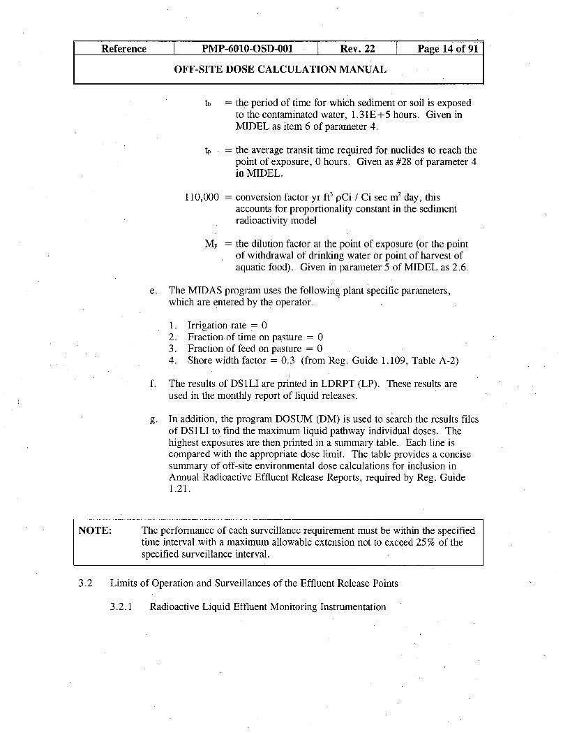
tb = the period of time for which sediment or soil is exposedto the contaminated water, 1.31E+5 hours. Given inMIDEL as item 6 of parameter 4.
tp = the average transit time required for nuclides to reach thepoint of exposure, 0 hours. Given as #28 of parameter 4in MIDEL.
110,000 = conversion factor yr ft3 pCi / Ci sec m2 day, thisaccounts for proportionality constant in the sedimentradioactivity model
Mp= the dilution factor at the point of exposure (or the pointof withdrawal of drinking water or point of harvest ofaquatic food). Given in parameter 5 of MIDEL as 2.6.
e. The MIDAS program uses the following plant specific parameters,which are entered by the operator.
1. Irrigation rate = 02. Fraction of time on pasture = 03. Fraction of feed on pasture = 04. Shore width factor - 0.3 (from Reg. Guide 1.109, Table A-2)
f. The results of DS 1LI are printed in LDRPT (LP). These results areused in the monthly report of liquid releases.
g. In addition, the program DOSUM (DM) is used to search the results filesof DS1LI to. find the maximum liquid pathway individual doses. Thehighest exposures are then printed in a summary table. Each line iscompared with the appropriate dose limit. The table provides a concisesummary of off-site environmental dose calculations for inclusion inAnnual Radioactive Effluent Release Reports, required by Reg. Guide1.21.
NOTE: The performance of each surveillance requirement must be within the specifiedtime interval with a maximum allowable extension not to exceed 25 % of thespecified surveillance interval.
3.2 Limits of Operation and Surveillances of the Effluent Release Points
3.2.1 Radioactive Liquid Effluent Monitoring Instrumentation

Reference PMP-6010-OSD-001 Rev. 22 Page 15 of 91
OFF-SITE DOSE CALCULATION MANUAL
a. The radioactive liquid effluent monitoring instrumentation channelsshown in Attachment 3.2, Radioactive Liquid Effluent MonitoringInstruments, are operable with their alarm/trip setpoints set to ensurethat the limits of step 3.2.3a, Concentration Excluding Releases via theTurbine Room Sump (TRS) Discharge, are not exceeded.
b. The applicability of each channel is shown in Attachment 3.2,Radioactive Liquid Effluent Monitoring Instruments.
c. With a radioactive liquid effluent monitoring instrumentation channelalarm/trip setpoint less conservative than a value which will ensure thelimits of step 3.2.3a, Concentration Excluding Releases via the TurbineRoom Sump (TRS) Discharge, are met without delay, suspend therelease of radioactive liquid effluents monitored by the affected channeland reset or declare the monitor inoperable.
d. With one or more radioactive liquid effluent monitoring instrumentationchannels inoperable, take the applicable action shown in Attachment 3.2,Radioactive Liquid Effluent Monitoring Instruments, with a maximumallowable extension not to exceed 25 % of the surveillance interval,excluding the initial performance.
e. Determine the setpoints in accordance with the methodology described instep 3.3.1, Liquid Monitors. Record the setpoints..
f. Demonstrate each radioactive liquid effluent monitoring instrumentationchannel is operable by performing the CHANNEL CHECK, SOURCECHECK, CHANNEL CALIBRATION and CHANNELOPERATIONAL TEST at the frequencies shown in Attachment 3.3,Radioactive Liquid Effluent Monitoring Instrumentation SurveillanceRequirements.
BASES - LIQUID
The radioactive liquid effluent instrumentation is provided to monitor and control, asapplicable, the releases of radioactive materials in liquid effluents during actual or potentialreleases. The alarm/trip setpoints for these instruments shall be calculated in accordancewith NRC approved methods in the ODCM to ensure the alarm/trip will occur prior toexceeding the limits of 10 CFR Part 20. The OPERABILITY and use of thisinstrumentation is consistent with the requirements of General Design Criteria specified inSection 11.3 of the Final Safety Analysis Report for the Donald C. Cook Nuclear Plant.Due to the location of the Westinghouse ESW monitors, outlet line of containment sprayheat exchanger (typically out of service), weekly sampling is required of the ESW systemfor radioactivity. This is necessary to ensure monitoring of a CCW to ESW system leak.[Ref 5.2. lgg]

Reference PMP-6010-OSD-001 Rev. 22 Page 16 of 91
OFF-SITE DOSE CALCULATION MANUAL
3.2.2 Radioactive Gaseous Effluent Monitoring Instrumentation
a. The radioactive gaseous process and effluent monitoring instrumentationchannels shown in Attachment 3.4, Radioactive Gaseous EffluentMonitoring Instrumentation, are operable with their alarm/trip setpointsset to ensure that the limits of step 3.2.4a, Dose Rate, are not exceeded.
b. The applicability of each channel is shown in Attachment 3.4,Radioactive Gaseous Effluent Monitoring Instrumentation.
c. With a radioactive gaseous process or effluent monitoringinstrumentation channel alarm/trip setpoint less conservative than a valuewhich will ensure that the limits of step 3.2.4a, Dose Rate, are met,without delay, suspend the release of radioactive gaseous effluentsmonitored by the affected channel and reset or declare the channelinoperable.
d. With less than the minimum number of radioactive gaseous effluentmonitoring instrumentation channels operable, take the action shown inAttachment 3.4, Radioactive Gaseous Effluent MonitoringInstrumentation, with a maximum allowable extension not to exceed25 % of the surveillance interval; excluding the initial performance.
NOTE: This surveillance requirement does not apply to the waste gas holdup systemhydrogen and oxygen monitors, as their setpoints are not addressed in thisdocument.
e. Determine the setpoints in accordance with the methodology as describedin step 3.3.2, Gaseous Monitors. Record the setpoints.
f. Demonstrate each radioactive gaseous process or effluent monitoringinstrumentation channel is operable by performing the CHANNELCHECK, SOURCE CHECK, CHANNEL CALIBRATION, andCHANNEL OPERATIONAL TEST operations at the frequencies shownin Attachment 3.5, Radioactive Gaseous Effluent MonitoringInstrumentation Surveillance Requirements.
BASES - GASEOUS
The radioactive gaseous effluent instrumentation is provided to monitor and control, asapplicable, the releases of radioactive materials in gaseous effluents during actual orpotential releases. The alarm/trip setpoints for these instruments shall be calculated inaccordance with NRC approved methods in the ODCM to ensure the alarm/trip will occurprior to exceeding the limits of 10 CFR Part 20. The OPERABILITY and use of thisinstrumentation is consistent with the requirements of General Design Criteria specified inSection 11.3 of the Final Safety Analysis Report for the Donald C. Cook Nuclear Plant.
Reference PMP-6010-OSD-001 Rev. 22 Page 17 of 91
OFF-SITE DOSE CALCULATION MANUAL
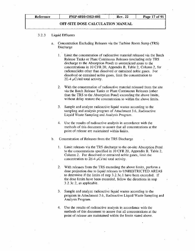
3.2.3 Liquid Effluents
a. Concentration Excluding Releases via the Turbine Room Sump (TRS)Discharge
1. Limit the concentration of radioactive material released via the BatchRelease Tanks or Plant Continuous Releases (excluding only TRSdischarge to the Absorption Pond) to unrestricted areas to theconcentrations in 10 CFR 20, Appendix B, Table 2, Column 2, forradionuclides other than dissolved or entrained noble gases. Fordissolved or entrained noble gases, limit the concentration to2E-4 gCi/ml total activity.
2. With the concentration of radioactive material released from the sitevia the Batch Release Tanks or Plant Continuous Releases (otherthan the TRS to the Absorption Pond) exceeding the above limits,without delay restore the concentration to within the above limits.
3. Sample and analyze radioactive liquid wastes according to thesampling and analysis program of Attachment 3.6, RadioactiveLiquid Waste Sampling and Analysis Program.
4. Use the results of radioactive analysis in accordance with themethods of this document to assure that all concentrations at thepoint of release are maintained within limits.
b. Concentration of Releases from the TRS Discharge
1. Limit releases via the TRS discharge to the on-site Absorption Pondto the concentrations specified in 10 CFR 20, Appendix B, Table 2,Column 2. For dissolved or entrained noble gases, limit theconcentration to 2E-4 uCi/ml total activity.
2. With releases from the TRS exceeding the above limits, perform adose projection due to liquid releases to UNRESTRICTED AREASto determine if the limits of step 3.2.3c.1 have been exceeded. Ifthe dose limits have been exceeded, follow the directions in step3.2.3c.2, as applicable.
3. Sample and analyze radioactive liquid wastes according to theprogram in Attachment 3.6, Radioactive Liquid Waste Sampling andAnalysis Program.
4. Use the results of radioactive analysis in accordance with themethods of this document to assure that all concentrations at thepoint of release are maintained within the limits stated above.
Reference PMP-6010-OSD-001 Rev. 22 Page 18 of 91
OFF-SITE DOSE CALCULATION MANUAL
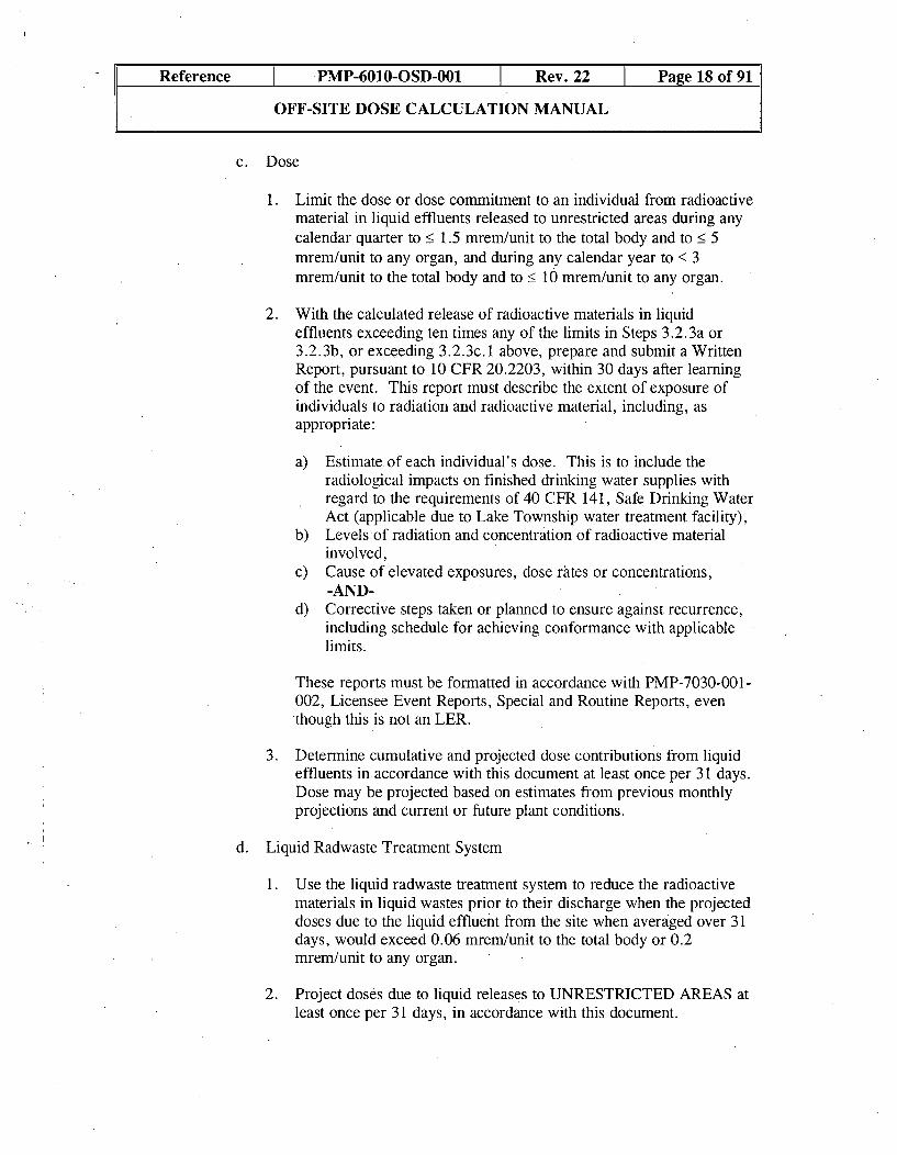
c. Dose
1. Limit the dose or dose commitment to an individual from radioactivematerial in liquid effluents released to unrestricted areas during anycalendar quarter to < 1.5 mrem/unit to the total body and to __ 5mrem/unit to any organ, and during any calendar year to < 3mrem/unit to the total body and to _< 10 mrem/unit to any organ.
2. With the calculated release of radioactive materials in liquideffluents exceeding ten times any of the limits in Steps 3.2.3a or3.2.3b, or exceeding 3.2.3c. 1 above, prepare and submit a WrittenReport, pursuant to 10 CFR 20.2203, within 30 days after learningof the event. This report must describe the extent of exposure ofindividuals to radiation and radioactive material, including, asappropriate:
a) Estimate of each individual's dose. This is to include theradiological impacts on finished drinking water supplies withregard to the requirements of 40 CFR 141, Safe Drinking WaterAct (applicable due to Lake Township water treatment facility),
b) Levels of radiation and concentration of radioactive materialinvolved,
c) Cause of elevated exposures, dose rates or concentrations,-AND-
d) Corrective steps taken or planned to ensure against recurrence,including schedule for achieving conformance with applicablelimits.
These reports must be formatted in accordance with PMP-7030-001-002, Licensee Event Reports, Specialand Routine Reports, eventhough this is not an LER.
3. Determine cumulative and projected dose contributions from liquideffluents in accordance with this document at least once per 31 days.Dose may be projected based on estimates from previous monthlyprojections and current or future plant conditions.
d. Liquid Radwaste Treatment System
1. Use the liquid radwaste treatment system to reduce the radioactivematerials in liquid wastes prior to their discharge when the projecteddoses due to the liquid effluent from the site when averaged over 31days, would exceed 0.06 mrem/unit to the total body or 0.2mrem/unit to any organ.
2. Project doses due to liquid releases to UNRESTRICTED AREAS atleast once per 31 days, in accordance with this document.

Reference PMP-6010-OSD-001 Rev. 22 Page 19 of 91
OFF-SITE DOSE CALCULATION MANUAL
e. During times of primary to secondary leakage, the use of the startup flashtank should be minimized to reduce the release of curies from thesecondary system and to maintain the dose to the public ALARA.Operation of the NorthBoric Acid Evaporator (NBAE) should be done ina manner so as to allow the recycle of the distillate water to the PrimaryWater Storage Tank for reuse. This will provide a large reduction inliquid curies of tritium released to the environment, as there isapproximately 40 curies of tritium released with every monitor tank ofNBAE distillate.
Drainage of high conductivity water (Component Cooling Water and icemelt water containing sodium tetraborate) shall be evaluated to decidewhether it should be drained to waste (small volumes only), the TurbineRoom Sump (low activity water only) or routed without demineralizationprocessing to a monitor tank for release.-, This is necessary in order tominimize the detrimental affect that high conductivity water has on theradioactive wastewater demineralization system. The standardconcentration and volume equation can be utilized to determine theimpact on each method and is given here. The units for concentrationand volume need to be consistent across the equation:
(C)V)+ (Co)(WI) ='(CQ(V,)
Where;
Ci = the initial concentration of the system being added toVi = the initial volume of the system being added toCa = the concentration of the water that is being added to the systemVa = the volume of the water that is being added to the systemCt = the final concentration of the system after the additionVt = the final volume of the system after the addition
The intent is to keep the:
* WDS below 500 Vinmhos/cc.* TRS below lE-5 jiC/cc.* Monitor Tank release ALARA to members of the public.
Wastewater leakage into the liquid waste disposal system will bemonitored routinely. In the event the leak rate is determined to be overtwo gallons per minute (the assumed plant design leakage based on theoriginal 2 gpm waste evaporator), increased scrutiny will be placed onlocating inleakage, timeliness of job order activities, and/or activitiescausing increased production of waste water.

Reference PMP-6010-OSD-001 I Rev. 22 Page 20 of 91
OFF-SITE DOSE CALCULATION MANUAL
BASES - CONCENTRATION
This specification is provided to ensure the concentration of radioactive materials released inliquid waste effluents from the site to unrestricted areas will be less than the concentrationlevels specified in 10 CFR Part 20, Appendix B, Table 2. This limitation providesadditional assurance that the levels of radioactive materials in bodies of water outside thesite will not result in exposures greater than 1) the Section II.A design objectives ofAppendix I, 10 CFR Part 50, to an individual and 2) the limits of 10 CFR Part 20. Theconcentration limit for noble gasses is based upon the assumption that Xe-135 is thecontrolling radionuclide and its Effluent Concentration Unit in air (submersion) wasconverted to an equivalent concentration in water using the methods described in theInternational Commission on Radiological Protection (ICRP) Publication 2.
DOSE
This specification is provided to implement the requirements of Sections II.A, III.A, andIV.A of Appendix I, 10 CFR Part 50. The dose limits iniplement the guides set forth inSection II.A of Appendix I. The ACTION statements provide the required operatingflexibility and at the same time, implement the guides set forth in Section IV.A of AppendixI to assure the releases of radioactive material in. liquid effluents will be kept "as low as isreasonably achievable". Also, for fresh water sites with-drinking water supplies which canbe potentially affected b' plant operations, there is reasonable assurance that the operationof the facility will not result in radionuclide concentrations in the finished drinking waterthat are in excess of the requirements of 40 CFR 141. The dose calculations in the ODCMimplement the requirements in Section III.A of Appendix I that conformance with the guidesof Appendix I be shown by calculational procedures based on models and data such that theactual exposure of an individual through appropriate pathways is unlikely to be substantiallyunderestimated. The equations specified in the ODCM for calculating the doses due to theactual release rates of radioactive materials in liquid effluents, will be consistent with themethodology provided in Regulatory Guide 1.109, "Calculation of Annual Doses to Manfrom Routine Releases of Reactor Effluents for the Purpose of Evaluating Compliance with10 CFR Part 50, Appendix I", Revision 1, October 1977, and Regulatory Guide 1.113,"Estimating Aquatic Dispersion of Effluents from Accidental and Routine Reactor Releasesfor the Purpose of Implementing Appendix I", April 1977. NUREG-0133 provides methodsfor dose calculations consistent with Regulatory Guide 1.109 and 1.113.
This specification applies to the release of liquid effluents from each reactor at the site. Theliquid effluents from the shared system are proportioned among the units sharing the system.

Reference PMP-6010-OSD-001 Rev., 22 Page 21 of 91
OFF-SITE DOSE CALCULATION MANUAL
LIQUID WASTE TREATMENT
The operability of the liquid radwaste treatment system ensures that this system will beavailable for use whenever liquid effluents require treatment prior to release to theenvironment. The requirements that the appropriate portions of this system be used whenspecified provide assurance that the releases of radioactive materials in liquid effluents willbe kept "as low as is reasonably achievable". This specification implements therequirements of 10 CFR Part 50.36a, General Design Criteria Section 11.1 of the FinalSafety Analysis Report for the Donald C. Cook Nuclear Plant, and design objective SectionII.D of Appendix I to 10 CFR Part 50. The specified limits governing the use ofappropriate portions of the liquid radwaste treatment system were specified as a suitablefraction of the dose design objectives set forth in Section II.A of Appendix I, 10 CFR Part50, for liquid effluents.
3.2.4 Gaseous Effluents
a. Dose Rate
1. Limit the dose rate due to radioactive materials released in gaseouseffluents from the site to •< 500 mrem/yr to the total body and_ 3000 mrem/yr to the skin for noble gases. Limit the dose rate due
to all radioiodines and for all radioactive materials in particulateform and radionuclides (other than noble gases) with half-livesgreater than eight days to < 1500 mrem/yr to any organ.
2. With the dose rate(s) exceeding the above limits, without delaydecrease the release rate to within the above limit(s).
3. Determine the dose rate due to noble gases in gaseous effluents to bewithin the above limits in accordance with the methods andprocedures described in this document.
4. Determine the dose rate due to radioactive materials, other thannoble gases, in gaseous effluents to be within the above limits inaccordance with the methods and procedures of this document byobtaining representative samples and performing analyses inaccordance with the sampling and analysis program in Attachment3.7, Radioactive Gaseous Waste Sampling and Analysis Program.
b. Dose - Noble Gases
1. Limit the air dose in unrestricted areas due to noble gases released ingaseous effluents during any calendar quarter, to _ 5 mrad/unit forgamma radiation and < 10 mrad/unit for beta radiation and duringany calendar year, to • 10 mrad/unit for gamma radiation and • 20mrad/unit for beta radiation.

Reference PMP-6010-OSD-001 I Rev. 22 Page 22 of 91
OFF-SITE DOSE CALCULATION MANUAL
2. With the calculated air dose from radioactive noble gases in gaseouseffluents exceeding any of the above limits, prepare and submit aWritten Report, pursuant to 10 CFR 20.2203 and addressed in step3.2.3c.2, within 30 days after learning of the event.
3. Determine cumulative and projected dose contributions for the total timeperiod in accordance with this document at least once every 31 days.
c. Dose - Iodine-131, Iodine-133, Tritium, and Radioactive Material inParticulate Form
1. Limit the dose to a MEMBER OF THE PUBLIC from radioiodine,radioactive materials in particulate form, and radionuclides other thannoble gases wvith half-lives greater than eight days in gaseous effluentsreleased to unrestricted areas (site boundary) to the following:
a) During any calendar quarter to less than or equal to 7.5mrem/unit to any organ
b) During any calendar year to less than- or equal to 15 mrem/unitto any organ.
2. With the calculated dose from the release of radioiodines,radioactive materials in particulate form, or radionuclides other thannoble gases in gaseous effluents exceeding any of the above limits,prepare and submit a Written Report, pursuant to 10 CFR 20.2203and addressed in step 3.2.3c.2, within 30 days after learning of theevent.
3. Determine cumulative and projected dose contributions for the totaltime period in accordance with this document at least once every 31days.
d. Gaseous Radwaste Treatment
1. Use the gaseous radwaste treatment system and the ventilation exhausttreatment system to reduce radioactive materials in gaseous wastesprior to their discharge when projected gaseous effluent air doses dueto gaseous effluent releases to unrestricted areas when averaged over31 days, would exceed 0.2 mrad/unit for gamma radiation and 0.4mrad/unit for beta radiation. Use the ventilation exhaust treatmentsystem to reduce radioactive materials in gaseous waste prior to theirdischarge when the projected doses due to gaseous effluent releases tounrestricted areas when averaged over 31 days would exceed 0.3mrem/unit to any organ.
2. Project doses due to gaseous releases to UNRESTRICTED AREAS atleast once per 31 days in accordance with this document.

Reference T PMP-6010-OSD-001 ý Rev. 22 I Page 23 of 91
OFF-SITE DOSE CALCULATION MANUAL
BASES -- GASEOUS EFFLUENTS
This specification provides reasonable assurance that radioactive material discharged in gaseouseffluents will not result in the exposure of a Member of the Public in an unrestricted area,either at or beyond the site boundary in excess of the design objectives of appendix I to 10CFR 50. This specification is provided to ensure that gaseous effluents from all units on thesite will be appropriately controlled. It provides operational flexibility for releasing gaseouseffluents to satisfy the Section II.A and II.C design objectives of appendix I to 10 CFR 50.For individuals who may at times be within the site boundary, the occupancy of the individualwill be sufficiently low to compensate for any increase in the atmospheric diffusion factorabove that for the site boundary. The specified instantaneous release rate limits restrict, at alltimes, the corresponding gamma and beta dose rates above background to an individual at orbeyond the site boundary to _• 500 mrem/yr to the total body or to _ 3000 mrem/yr to the skin.These instantaneous release rate limits also restrict, at all times, the corresponding thyroid doserate above background to a child via the inhalation pathway to _• 1500 mrem/yr. Limitationson the dose rate resulting from radioactive material released in gaseous effluents to areasbeyond the site boundary conforming to the doses associated with 10 CFR 20, Appendix B,Table 2, Column 1.
This specification applies to the release of gaseous effluents from all reactors at the site. Thegaseous effluents from the shared system are proportioned among the units sharing that system.
DOSE, NOBLE GASES
This specification is provided to implement the requirements of Sections II.B, III.A, and IV.A.of Appendix I, 10 CFR Part 50. The dose limits implement the guides set forth in Section II.Bof Appendix I.
The ACTION statements provide the required operating flexibility and at the same timeimplement the guides set forth in section IV.A of Appendix I to assure that the releases ofradioactive material in gaseous effluents will be kept "as low as is reasonably achievable".The Surveillance Requirements implement the requirements in Section III.A of Appendix I thatconform with-the guides of Appendix I to be shown by calculational procedures based onmodels and data such that the actual exposure of an individual through the appropriatepathways is unlikely to be substantially underestimated. The dose calculations established inthe ODCM for calculating the doses due to the actual release rates of radioactive noble gases ingaseous effluents will be consistent with the methodology provided in Regulatory Guide 1.109,"Calculation of Annual Doses to Man from Routine Releases of Reactor Effluents for thePurpose of Evaluating Compliance with 10 CFR Part 50, Appendix I", Revision 1, October1977 and Regulatory Guide 1.111, "Methods for Estimating Atmospheric Transport andDispersion of Gaseous Effluents in Routine Releases from Light-Water-Cooled Reactors",Revision 1, July 1977. The ODCM equations provided for determining the air doses at the siteboundary will be based upon the historical average atmospherical conditions. NUREG-0133provides methods for dose calculations consistent with Regulatory Guides 1.109 and 1.111.

Reference T PMP-6010-OSD-001 I Rev. 22 1 Page 24 of 91
OFF-SITE DOSE CALCULATION MANUAL
DOSE, RADIOIODINES, RADIOACTIVE MATERIAL IN PARTICULATE FORM, ANDRADIONUCLIDES OTHER THAN NOBLE GASES
This specification is provided to implement the requirements of Sections II.C, III.A, and IV.Aof Appendix I, 10 CFR Part 50. The dose limits are the guides set forth in Section II.C ofAppendix I.
The ACTION statements provide the required operating flexibility and at the same timeimplement the guides set forth in section IV.A of Appendix I to assure that the releases ofradioactive material in gaseous effluents will be kept "as low as is reasonably achievable".The ODCM calculational methods specified in the surveillance requirements implement therequirements in Section III.A of Appendix I that conform with the guides of Appendix I to beshown by calculational procedures based on models and data such that the actual exposure ofan individual through the appropriate pathways is unlikely to be substantially underestimated.The ODCM calculational methods approved by the NRC for calculating the doses due to theactual release rates of the subject materials are required to be consistent with the methodologyprovided in Regulatory Guide 1. 109, "Calculation of Annual Doses to Man from RoutineReleases of Reactor Effluents for the Purpose of Evaluating Compliance with 10 CFR Part 50,Appendix I", Revision 1, October 1977 and Regulatory Guide 1.111, "Methods for EstimatingAtmospheric Transport and Dispersion of Gaseous Effluents in Routine Releases from Light-Water-Cooled Reactors", Revision 1, July 1977. These equations also provide themethodology for determining the actual doses based upon the historical average atmosphericconditions. The release rate specifications for radioiodines, radioactive material in particulateform, and radionuclides, other than noble gases, are dependent on the existing radionuclidepathways to man, in the unrestricted area. The pathways which are examined in thedevelopment of these calculations are: 1) individual inhalation of airborne radionuclides, 2)deposition of radionuclides onto green leafy vegetation with subsequent consumption by man,3) deposition onto grassy areas where milk animals and meat producing animals graze withconsumption of the milk and meat by man, and 4) deposition on the ground with subsequentexposure of man.
GASEOUS WASTE TREATMENT
The operability of the gaseous radwaste treatment system and the ventilation exhaust treatmentsystems ensures that the systems will be available for use whenever gaseous effluents requiretreatment prior to release to the environment. The requirement that the appropriate portions ofthese systems be used when specified provides reasonable assurance that the releases ofradioactive materials in gaseous effluents will be kept "as low as is reasonably achievable".This specification implements the requirements of 10 CFR Part 50.36a, General DesignCriterion Section 11. 1 of the Final Safety Analysis Report for the Donald C. Cook NuclearPlant, and design objective Section II.D of Appendix I to 10 CFR Part 50. The specified limitsgoverning the use of appropriate portions of the systems were specified as a suitable fraction ofthe guides forth in Sections II.B and II.C of Appendix I, 10 CFR Part 50, for gaseouseffluents.

Reference PMP-6010-OSD-001 I Rev. 22. Page 25 of 91
OFF-SITE DOSE CALCULATION MANUAL J
3.2.5 Radioactive Effluents - Total Dose
a. The dose or dose commitment to a real individual from all uranium fuelcycle sources is limited to _< 25 mrem to the total body or any organ(except the thyroid, which is limited to _< 75 mrem) over a period of 12consecutive months.
b. With the calculated doses from the release of radioactive materials inliquid or gaseous effluents exceeding twice the limits of steps 3.2.3c(Dose), 3.2.4b (Dose - Noble Gases), or 3.2.4c (Dose - Iodine-131,Iodine-133, Tritium, and Radioactive Material in Particulate Form)during any calendar quarter, perform the following:
• Investigate and identify the causes for such release rates;" Define and initiate a program for corrective action;* Report these actions to the NRC within 30 days from the end of the
quarter during which the release occurred.
IF the estimated dose(s) exceeds the limits above, and IF the releasecondition resulting in violation has not already been corrected prior toviolation of 40 CFR 190, THEN include in the report a request for avariance in accordance with the provisions of 40 CFR 190 and includingthe specified information of paragraph 190.1 (b). Submittal of thereport is considered a timely request, and a variance is granted until staffaction on the request is complete. The variance only relates to the limitsof 40 CFR 190, and does not apply in any way to the requirements fordose limitation of 10 CFR 50, as addressed in other sections of thisdocument.
c. Determine cumulative dose contributions from liquid and gaseouseffluents in accordance with this document (including steps 3.2.3c[Dose], 3.2.4b [Dose - Noble Gases], or 3.2.4c [Dose - Iodine-131,Iodine-133, Tritium, and Radioactive Material in Particulate Form]).

Reference PMP-6010-OSD-001 Rev. 22 Page' 26 of 91
OFF-SITE DOSE CALCULATION MANUAL
BASES -- TOTAL DOSE
This specification is provided to meet the dose limitations of 40 CFR 190. The specificationrequires the preparation and submittal of a Special Report whenever the calculated doses fromplant radioactive effluents exceed twice the design objective doses of Appendix I. For sitescontaining up to 4 reactors, it is highly unlikely that the resultant dose to a member of the publicwill exceed the dose limits of 40 CFR 190 if the individual reactors remain within the reportingrequirement level. The Special Report will describe a course of action, which should result inthe limitations of dose to a member of the public for 12 consecutive months to within the40 CFR 190 limits. For the purposes of the Special Report, it may be assumed that the dosecommitment to any member of the public from other uranium fuel cycle sources is negligiblewith the exception that dose contributions from other nuclear fuel cycle facilities at the same siteor within a radius of 5 miles must be considered. If the dose to any member of the public isestimated to exceed the requirements of 40 CFR 190, the Special Report with a request for avariance (provided the release conditions resulting in violation of 40 CFR 190 have not alreadybeen corrected, in accordance with the provision of 40 CFR 190.11), is considered to be atimely request and fulfills the requirements of 40 CFR 190 until NRC staff action is completed.An individual is not considered a member of the public during any period in which he/she isengaged in carrying out any operation, which is part of the nuclear fuel cycle.
3.3 Calculation of Alarm/Trip Setpoints
The alarm and trip setpoints are to, provide monitoring, indication, and control of liquidand gaseous effluents. The setpoints' are used in conjunction with sampling programs toassure that the releases are kept within the limits of 10 CFR 20, Appendix B, Table 2.Establish setpoints for liquid and gaseous monitors. Depending on the monitor function,it would be a continuous or batch monitor. The different types of monitors are subject todifferent setpoint methodologies.
One variable used in setpoint calculations is the multiple release point (MRP) factor.The MRP is a factor used such that when all the releases are integrated, the applicableLIMIT value will not be exceeded. The MRP is determined such that the sum of theMRP's for that effluent type (liquid or gaseous) is less than or equal to 1. The value ofthe MRP is arbitrary, and it should be assigned based on operational performance. Thevalues of the MRP's for each liquid release point are given in Attachment 3.8, MultipleRelease Point Factors for Release Points.
The Site stance on instrument uncertainty is taken from HPPOS-223, Consideration ofMeasurement Uncertainty When Measuring Radiation Levels Approaching RegulatoryLimits, which states the NRC position is the result of a valid measurement obtained by amethod, which provides a reasonable demonstration of compliance. This value shouldbe accepted and the uncertainty in that measured value need not be considered.

Reference PMP-6010-OSD-001 Rev. 22 Page 27 of 91
OFF-SITE DOSE CALCULATION MANUAL
3.3.1 Liquid Monitors
Establish liquid monitor setpoints for each monitor of the liquid effluent releasesystems. A schematic of the liquid effluent release systems is shown asAttachment 3.9, Liquid Effluent Release Systems. A list of the Plant LiquidEffluent Parameters is in Attachment 3.10, Plant Liquid Effluent Parameters.The details of each system design and operation can be found in the systemdescriptions. The setpoints are intended to keep releases within the limits of10 CFR 20, Appendix B, Table 2, Column 2. Determine setpoints using eitherthe batch or the continuous methodology.
a. Liquid Batch Monitor Setpoint Methodology
1. There is only one monitor used on the Waste Disposal System for liquidbatch releases. This monitor is identified as RRS-1000. SteamGenerator Blowdown radiation monitors also can be used to monitorbatch releases while draining steam generators. The function of thesemonitors is to act as a check on the sampling program. The samplingprogram determines the nuclides and concentrations of those nuclidesprior to release. The discharge and dilution flow rates are then adjustedto keep the release within the limits of 10 CFR 20. Based on theconcentrations of nuclides in the release, the count rate on the monitorcan be predicted. The high alarm setpoint can then be set above thepredicted value up.to the maximum setpoint of the system.
2. The radioactive concentration of each batch of radioactive liquidwaste to be discharged is determined prior to each release bysampling and analysis in accordance with Attachment 3.6,Radioactive Liquid Waste Sampling and Analysis Program.
3. The allowable release flow rates are determined in order to keep therelease concentrations within the requirements of 10 CFR 20,Appendix B, Table 2, Column 2. The equation to calculate the flowrate is from Addendum AA1 of NUREG-0133:
L Ci LMT f _<F+fLIMTTi M ARP
Where;
Ci = the concentration of nuclide "i" in .tCi/ml
LIMIT = the 10 CFR 20, Appendix B, Table 2, Column 2 limit ofnuclide "i" in p.Ci/ml
f = the effluent flow rate in gpm (Attachment 3.10, PlantLiquid Effluent Parameters)
F = the dilution water flow rate as estimated prior to release.The dilution flow rate is a multiple of 230,000 gpmdepending on the number of circulation pumps in operation.

Reference PMP-6010-OSD-001 Rev. 22 Page 28 of 91
OFF-SITE DOSE CALCULATION MANUAL
MRP = the multiple release point factor. A factor such thatwhen all the release points are operating at one time thelimits of 10 CFR 20 will not be exceeded.
4. This equation must be true during the batch release. Before therelease is started, substitute the maximum effluent flow rate and theminimum dilution flow rate for f and F, respectively. If theequation is true, the release can proceed with those flow rates as thelimits of operation. If the equation is not true, the effluent flow ratecan be reduced or the dilution flow rate can be increased to make theequation true. This equation may be rearranged to solve for themaximum effluent release flow rate (f).
5. The setpoint is used as a quality check on the sampling program.The setpoint is used to stop the effluent flow when the monitorreading is greater than the predicted value from the samplingprogram. The predicted value is generated by converting theeffluent concentration for each gamma emitting radionuclide tocounts per unit of time as per Attachment 3.11, VolumetricDetection Efficiencies for Principle Gamma Emitting Radionuclidesfor Eberline Liquid Monitors, or Attachment 3.12, CountingEfficiency Curves for R-19, and R-24ý The sum of all the countsper unit of time is the predicted. count rate. The predicted count ratecan then be multiplied by a factor to determine the high alarmsetpoint that will provide a high degree of conservatism andeliminate spurious alarms.
b. Liquid Continuous Monitor Setpoint Methodology
1. There are eight monitors used as potential continuous liquid releasemonitors. These monitors are used in the steam generatorblowdown (SGBD), blowdown treatment (BDT), and essentialservice water (ESW) systems.
2. These Westinghouse monitors (R) are being replaced by Eberlinemonitors (DRS) and are identified as:
• R-19 or DRS 3100/4100 for SGBD° R-24 or DRS 3200/4200 for BDT
The function of these monitors is to assure that releases are keptwithin the concentration limits of 10 CFR 20, Appendix B, Table 2,Column 2, entering the unrestricted area following dilution.

Reference PMP-6010-OSD-001 I Rev. 22 Page 29 of 91
OFF-SITE DOSE CALCULATION MANUAL
3. The monitors on steam generator blowdown and blowdowntreatment systems have trip functions associated with their setpoints.Essential service water monitors are equipped with an alarmfunction only and monitor effluent in the event the ContainmentSpray Heat Exchangers are used.
4. The equation used to determine the setpoint for continuous monitorsis from Addendum AA1 of NUREG-0133:
S C*Eff *MRP*F*SFf
Where;
Sp = setpoint of monitor (cpm)
C = 5E-7 pCi/ml, maximum effluent control limit from10 CFR 20, Appendix B, Table 2, Column 2 of a knownpossible nuclide in effluent stream. (The limiting nuclideshall be evaluated annually by reviewing current nuclidesagainst historical ones in order to determine if one with amore restrictive effluent concentration limit than Sr90 isfound. The concentration limit shall be adjustedappropriately.)-OR-if a mixture is-to be specified,
Zc,Ci
LIMITi
Eff = Efficiency, this information is located in Attachment3.11, Volumetric Detection Efficiencies for PrincipleGamma Emitting Radionuclides for Eberline LiquidMonitors, through Attachment 3.13, Counting EfficiencyCurve for R-20, and R-28, for the specific monitors. ForEberline monitors the efficiency is nuclide specific andthe calculation changes slightly to:
Y( Ci * Effi) replaces C * Eff
Ci
LIMITi

Reference PMP-6010-OSD-001 Rev. 22 Page 30 of 91
OFF-SITE DOSE CALCULATION MANUAL
MRP = multiple release point factor. A factor such that when allthe release points are operating at one time the limits of10 CFR 20 will not be exceeded (Attachment 3.8,Multiple Release Point Factors for Release Points). TheMRP for ESW monitors is set to 1.
F = dilution water (circ water) flow rate in gpm obtainedfrom Attachment 3.10, Plant Liquid Effluent Parameters.For routine operation, the setpoint should be calculatedusing the minimum dilution flow rate of 230,000 gpm.
SF = Safety Factor, 0.9.
f = applicable effluent release flow rate in gpm. For routineoperation, the setpoint should be calculated usingmaximum effluent flow rate (Attachment 3.10, PlantLiquid Effluent Parameters).
3.3.2 Gaseous Monitors
For the purpose of implementing Step 3.2.2, Radioactive Gaseous EffluentMonitoring Instrumentation, and Substep 3.2.4a, Dose Rate, the alarmsetpoints for gaseous effluents released into unrestricted areas will beestablished using the following methodology. In addition, the above steps donot apply to instantaneous alarm and trip setpoints for integrating radiationmonitors sampling radioiodines, radioactive materials in particulate form andradionuclides other than noble gases. A schematic of the gaseous effluentrelease systems is presented in Attachment 3.14, Gaseous Effluent ReleaseSystems. Attachment 3.15, Plant Gaseous Effluent Parameters, presents theeffluent flow rate parameter(s)..
Gaseous effluent monitor high alarm setpoints will routinely be established at afraction of the maximum allowable setpoint (typically 10% of the setpoint) forALARA purposes. Alert alarms will normally be set to provide adequateindications of small changes in radiological conditions.
NOTE: IF the setpoint calculation methodology changes or the associated factorschange for Unit Vent, Air Ejector and/or Gland Seal monitors, THEN initiatea review by Emergency Planning to ensure that the requirements of 10 CFR50.54 (q) are maintained.
a. Plant Unit Vent

Reference PMP-6010-OSD-001 I Rev. 22 Page 31 of 91
OFF-SITE DOSE CALCULATION MANUAL
1 The gaseous effluents discharged from the plant vent will bemonitored by the plant vent radiation monitor low range noble gaschannel [Tag No. VRS-1505 (Unit 1), VRS-2505 (Unit 2)] to assurethat applicable alarms and trip actions (isolation of gaseous release)will occur prior to exceeding the limits in step 3.2.4, GaseousEffluents. The alarm setpoint values will be established using thefollowing unit analysis equation:
SF * MRP * DLjSp = _
Fp */Q* r (Wi* DCF.)
Where;
Sp = the maximum setpoint of the monitor in laCi/cc forrelease point p, based on the most limiting organ
SF = an administrative operation safety factor, less than 1.0
MRP = a weighted multiple release point factor (_< 1.0), such thatwhen all site gaseous releases are integrated, the applicabledose will not be exceeded based on the release rate of eacheffluent point. The MRP is an arbitrary value based on theratio of the release rate or the volumetric flow rate of eacheffluent point to the total respective flow rate value of theplant and will be consistent with past operational experience.The MRP is computed as follows:
* Compute the average release rate, Qp, (or thevolumetric flow rate, fQ) from each release point p.
• Compute XQp (or Xfp) for all release points.0 Ratio Qp/EQp (or fp/>lfp) for each release point..
This ratio is the MRP for that specific release point0 Repeat the above bullets for each of the site's eight
gaseous release points.
Fp the maximum volumetric flow rate of release point "p",at the time of the release, in cc/sec. The maximum UnitVent flow rate, by design, is 186,600 cfm for Unit 1 and143,400 cfm for Unit 2.
DLj = dose rate limit to organ "j" in an unrestricted area(mrem/yr).
Based on continuous releases, the dose rate limits, DLo,from step 3.2.4a, Dose Rate, are as follows:
" Total Body < 500 mrem/year" Skin < 3000 mrem/year" Any Organ< 1500 mrem/year

Reference PMP-6010-OSD-001 I Rev. 22 Page 32 of 91
OFF-SITE DOSE CALCULATION MANUAL
* / Q = The worst case annual average relative concentration inthe applicable sector or area, in sec/m3 (see Attachment3.16, 10 Year Average of 1995-2004 Data).
Wi = weighted factor for the radionuclide:
-CiZC,
Where,
Ci = concentration of the most abundant radionuclide "i"
Ck = total concentration of all identifiedradionuclides in that release pathway. Forbatch releases, this value may be set to 1 forconservatism.
DCFij dose conversion factor used to relate radiationdose to organ "j", from exposure toradionuclide "i" in mrem in3./ yr piCi. Seefollowing equations.
The dose conversion factor, DCFij, isdependent upon the organ of concern.
For the whole body: DCF1 j = I
Where;
Ki = whole body dose factor due to gammaemissions for each identified noble gasradionuclide in mrem m3 / yr ýiCi. SeeAttachment 3.18, Dose Factors.
For the skin: DCFij = L + 1.1MI
Where;
Li skin dose factor due to beta emissions foreach identified noble gas radionuclide, inmrem m3 / yr ýtCi. See Attachment3.18, Dose Factors.
1.1 the ratio of tissue to air absorptioncoefficient over the energy range of photons
* of interest. This ratio converts absorbeddose (mrad) to dose equivalent (mrem).

Reference PMP-6010-OSD-001 I Rev. 22 Page 33 of 91
OFF-SITE DOSE CALCULATION MANUAL
Mi = the air dose factor due to gammaemissions for each identified noble gasradionuclide in mrad m3 / yr ptCi. SeeAttachment 3.18, Dose Factors.
For the thyroid, via inhalation: DCFij = Pi
Where;
Pi = the dose parameter, for radionuclidesother than noble gas, for the inhalationpathway in mrem m3 / yr ptCi (and thefood and ground path, as appropriate).See Attachment 3.18, Dose Factors.
2. The plant vent radiation monitor low range noble gas high alarmchannel setpoint, Sp, will be set such that the dose rate inunrestricted areas to the whole body, skin and thyroid (or any otherorgan), whichever is most limiting, will be less than or equal to 500mrem/yr, 3000 mrem/yr, and 1500 mrem/yr respectively.
3. The thyroid dose is limited to the inhalation pathway only.
4. The plant vent radiation monitor low range noble gas setpoint, Sp,will be recomputed whenever gaseous releases like ContainmentPurge, Gas Decay Tanks and CVCS HUTs are discharged throughthe plant vent to determine the most limiting organ.
5. The high alarm setpoint, Sp, may be established at a lower valuethan the lowest computed value via the setpoint equation.
6. Containment Pressure Reliefs will not have a recomputed high alarmsetpoint, but will use the normal high alarm setpoint due to theirrandomness and the time constraints involved in recomputation.
7. At certain times, it may be desirable to increase the high alarmsetpoint, if the vent flow rate is decreased. This may beaccomplished in one of two ways.
Max Conc ( AiCi/cc) * Max Flowrate (cfm) New Max cinNew Max Concentration (,aCi/cc)
-OR-
Max Conc (,aCi/cc) * Max Flowrate (cfim) - New Max jiCi/ccNew Max Flowrate (cfm)
b. Waste Gas Storage Tanks

Reference T PMP-6010-OSD-001 I Rev. 22 Page 34 of 91
OFF-SITE DOSE CALCULATION MANUAL
1. The gaseous effluents discharged from the Waste Gas System are monitoredby the vent stack monitors VRS-1505 and VRS-2505.
2. In the event of a high radiation alarm, an automatic termination ofthe release from the waste gas system will be initiated from the plantvent radiation monitor low range noble gas channel (VRS-1505 orVRS-2505). Therefore, for any gaseous release configuration,which includes normal operation and waste gas system gaseousdischarges, the alarm setpoint of the plant vent radiation monitorwill be recomputed to determine the most limiting organ based on allgaseous effluent source terms.
Chemical and Volume Control System Hold Up Tanks (CVCSHUT), containing high gaseous oxygen concentrations, may bereleased under the guidance of waste gas storage tank utilizingapproved Operations' procedures.
3. It is normally prudent to allow 45 days of decay prior to releasinga Gas Decay Tank (GDT). There are extenuating, operationalcircumstances that may prevent this from occurring. Under thesecircumstances, such as high oxygen concentration creating acombustible atmosphere, it is prudent towaive the 45-day decayfor safety's sake.
c. Containment Purge and Exhaust System
1. Thegaseous effluents discharged by the Containment Purge andExhaust Systems and Instrumentation Room Purge and ExhaustSystem are monitored by the plant vent radiation monitor noble gaschannels (VRS-1505 for Unit 1, VRS-2505 for Unit 2); and alarmsand trip actions will occur prior to exceeding the limits in step3.2.4a, Dose Rate.
2. For the Containment System, a continuous air sample from thecontainment atmosphere is drawn through a closed, sealed system tothe radiation monitors (Tag No. ERS-1300/1400 for Unit 1 andERS-2300/2400 for Unit 2). During purges, these monitor setpointswill give a Purge and Exhaust Isolation signal upon actuation of highalarm setpoints for particulate and noble gas channels. The sampleis then returned to containment. Grab sample analysis is performedfor a Containment purge before release.
3. The Upper Containment area is monitored by normal range areagamma monitors (Tag No. VRS-1 101/1201 for Unit 1 andVRS-2101/2201 for Unit 2), which also give Purge and ExhaustIsolation Trip signals upon actuation of their high alarm.

Reference PMP-6010-OSD-001 • Rev. 22 Page 35 of 91
OFF-SITE DOSE CALCULATION MANUAL
4. For the Containment Pressure. Relief System, no sample is routinelytaken prior to release, but a sample is obtained twice per month.
5. The containment airborne and area monitors, upon actuation of theirhigh alarm, will automatically initiate closure of the Containmentand Instrument Room purge supply and exhaust duct valves andcontainment pressure relief system valves. Complete trip of allisolation control devices requires high alarm of one of the two TrainA monitors (ERS- 1300/2300 or VRS- 1101/2101) and one of the twoTrain B monitors (ERS-1400/2400 or VRS-1201/2201).
d. Steam Jet Air Ejector System (SJAE)
1. The gaseous effluents from the Steam Jet Air Ejector Systemdischarged to the environment are continuously monitored byradiation monitor (Tag No. SRA-1900 for Unit 1 and SRA-2900 forUnit 2). The monitor will alarm prior to exceeding the limits of step3.2.4a, Dose Rate. The alarm setpoint for the Condenser AirEjector System monitor will be based on the maximum air ejectorexhaust flow rate, (Attachment 3.15, Plant Gaseous EffluentParameters). The alarm setpoint valuewill be established using thefollowing unit analysis equation:
=SF *MRP* DLjSSJAE SF */ * •(w,*DCF)
Where;
SSJAE = the maximum setpoint, based on the most limitingorgan, in lICi/cc and where the other terms are aspreviously defined
e. Gland Seal Condenser Exhaust
1. The gaseous effluents from the Gland Seal Condenser Exhaustdischarged to the environment are continuously monitored byradiation monitor (Tag No. SRA-1800 for Unit 1 and SRA-2800 forUnit 2). The radiation monitor will alarm prior to exceeding thelimits of step 3.2.4a, Dose Rate. The alarm setpoint for the GSCEmonitor will be based on the maximum condenser exhaust flow rate(1260 CFM for Unit 1, 2754 CFM each for the two Unit 2 vents).The alarm setpoint value will be established using the following unitanalysis equation:

Reference PMP-6010-OSD-001 Rev. 22 Page 36 of 91
OFF-SITE DOSE CALCULATION MANUAL
SGSCE SF *MRP * DLjFp* X/Q* (Wi* DCFj)
Where;
SGSCE = the maximum setpoint, based on the most limitingorgan, in ptCi/cc and where the other terms are aspreviously defined
3.4 Radioactive Effluents Total Dose
.3.4.1 The cumulative dose contributions from liquid and gaseous effluents will bedetermined by summing the cumulative doses as derived in steps 3.2.3c(Dose), 3.2.4b (Dose - Noble Gases), and 3.2.4c (Dose - Iodine-131, Iodine-133, Tritium, and Radioactive Material in Particulate Form) of thisprocedure. Dose contribution from direct radiation exposure will be basedon the results of the direct radiation monitoring devices located at the REMPmonitoring stations. See NUREG-0133, section 3.8.
3.5 Radiological Environmental Monitoring Program (REMP)
3.5.1 Purpose of the REMP
a. The purpose of the REMP is to:
0 Establish baseline radiation and radioactivity concentrations in theenvirons prior to reactor operations,
* Monitor critical environmental exposure pathways,
* Determine the radiological impact, if any, caused by the operationof the Donald C. Cook Nuclear Plant upon the local environment.
b. The first purpose of the REMP was completed prior to the initialoperation of either of the two nuclear units at the Donald C. CookNuclear Plant Site. The second and third purposes of the REMP are anon-going operation and as such various environmental media andexposure pathways are examined. The various pathways and samplemedia used are delineated in Attachment 3.19, RadiologicalEnvironmental Monitoring Program Sample Stations, Sample Types,Sample Frequencies. Included is a list of the sample media, analysisrequired, sample stations, and frequency requirements for both collectionand analysis. Attachment 3.19, Radiological Environmental MonitoringProgram Sample Stations, Sample Types, Sample Frequencies, definesthe scope of the REMP for the Donald C. Cook Nuclear Plant.

Reference PMP-6010-OSD-001 I Rev. 22 Page 37 of 91
OFF-SITE DOSE CALCULATION MANUAL
3.5.2 Conduct of the REMP [Ref. 5.2.1u]
a. Conduct sample collection and analysis for the REMP in accordance withAttachment 3.19, Radiological Environmental Monitoring ProgramSample Stations, Sample Types, Sample Frequencies, Attachment 3.20,Maximum Values for Lower Limits of DetectionsA,B - REMP, andAttachment 3.21, Reporting Levels for Radioactivity Concentrations inEnvironmental Samples. These are applicable at all times. The on-sitemonitoring locations are shown on Attachment 3.22, On-Site MonitoringLocation - REMP, and the off-site monitoring locations are shown onAttachment 3.23, Off-Site Monitoring Locations - REMP.
1. Perform each surveillance requirement within the specified timeinterval in Attachment 3.19, Radiological EnvironmentalMonitoring Program Sample Stations, Sample Types, SampleFrequencies, with a maximum allowable extension not to exceed25 % of the surveillance interval.
2. If an environmental sample cannot be collected in accordance withstep 3.5.2a, submit a description of the reasons for deviation and theactions taken to prevent a reoccurrence as part of the AnnualRadiological Environmental Operating Report (AREOR).
3. Deviations from the required sampling schedule are permitted ifspecimens are unobtainable due to hazardous conditions, seasonalunavailability, or malfunction of automatic sampling equipment. Ifthe deviation from the required sampling schedule is due to themalfunction of automatic sampling equipment, make every effort tocomplete the corrective action prior to the end of the next samplingperiod.

Reference PMP-6010-OSD-001 Rev. 22 Page 38 of 91
OFF-SITE DOSE CALCULATION MANUAL
NOTE: Only one report per event is required.
NOTE: Radioactivity from sources other than plant effluents do not require a SpecialReport.
4. IF any of the following conditions are identified:
* A radionuclide associated with plant effluents is detected in anyREMP sample medium AND its concentration exceeded thelimits specified in Attachment 3.21, Reporting Levels forRadioactivity Concentrations in Environmental Samples,
* More than one radionuclide associated with plant effluents isdetected in any REMP sample medium AND the TotalFractional Level, when averaged over the calendar quarter, isgreater than or equal to 1.
THEN complete the following steps, as applicable:
* Submit a Special Report to the Nuclear Regulatory Commissionwithin 30 days.
* Submit a Special Report to designated state and localorganizations for groundwater or surface water media whichcould. be used as drinking water.
* Evaluate the following items for inclusion in Special Reports:
1) Release conditions2) Environmental factors3) Corrective actions4) Additional factors which may have contributed to the
identified levels
5. WHEN submission of a Special Report to designated state andlocal organizations is required, THEN perform the following:
* Communicate event specific information to designated state andlocal organization personnel by the end of the next business day.

Reference PMP-6010-OSD-001 Rev. 22 Page 39 of 91
OFF-SITE DOSE CALCULATION MANUAL
6. IF a currently sampled milk farm location becomes unavailable,THEN conduct a special milk farm survey within 15 days.
a) IF the unavailable location was an indicator farm, THEN analternate sample location may be established within eight milesof the Donald C. Cook Nuclear Plant, if one is available.
b) IF the unavailable location was a background farm, THEN analternate sample location may be established greater than 15 butless than 25 miles of the Donald C. Cook Nuclear Plant in oneof the less prevalent 'Wind direction sectors, if one is available.
c) IF a replacement farm is unobtainable and the total number ofindicator farms is less than three or the background farms is lessthan one, THEN perform monthly vegetation sampling in lieuof milk sampling when vegetation is available.
BASES - RADIOLOGICAL ENVIRONMENTAL MONITORING PROGRAM (REMP)
The REMP provides measurements of radiation and radioactive materials in those exposurepathways and for those radionuclides, which lead to the highest potential radiation exposuresof individuals resulting from the station operation. Thereby, this monitoring programsupplements~the radiological effluent monitoring program by verifying the measurableconcentration of radioactive materials and levels of radiation are not higher than expected onthe basis of the effluent measurements and modeling of the environmental exposurepathways. The initially specified REMP was effective for the first three years ofcommercial operation. Program changes may be initiated based on operational experiencein accordance with the requirements of Technical Specification 5.5.1 .c.
The detection capabilities, required by Attachment 3.20, Maximum Values for Lower Limitsof DetectionsA,B - REMP, are the state-of-the-art for routine environmental measurements inindustrial laboratories.
It should be recognized that the LLD is defined as a priori (before the fact) limitrepresenting the capability of a measurement system and not as a posteriori (after the fact)limit for a particular measurement. Analyses shall be performed in such a manner that thestated LLDs will be achieved under routine analysis conditions. Occasionally, backgroundfluctuations, unavoidably small sample sizes, the presence of interfering nuclides, or otheruncontrollable circumstances may render these LLDs unachievable. In such cases, thecontributing factors will be identified and described in the Annual RadiologicalEnvironmental Operating Report.
3.5.3 Annual Land Use Census [Ref. 5.2.lu]
a. Conduct a land use census and identify the location of the nearest milkanimal, the nearest residence and the nearest garden of greater than 500square feet producing fresh leafy vegetables in each of the ten landsectors within a distance of five miles.

Reference PMP-6010-OSD-001 I Rev. 22 Page 40 of 91
OFF-SITE DOSE CALCULATION MANUAL
b. In lieu of the garden census, grape and broad leaf vegetation sampling may beperformed as close to the site boundary as possible in a land sector, .containingsample media, with the highest average deposition factor (D/Q) value.
c. Conduct this land use census annually between the dates of-June 1 andOctober 1 by door-to-door survey, aerial survey, or by consulting localagricultural authorities.
1. With a land use census identifying a location(s), which yields acalculated dose or dose commitment greater than the values currentlybeing calculated in this document, make appropriate changes toincorporate the new location(s) within 30 days, if possible.
BASES -- LAND USE CENSUS
This is provided to ensure changes in the use of unrestricted areas are identified andmodifications to the monitoring program are made in accordance with requirements of TS6.8.4b, if required by the results of the census. This census satisfies the requirements ofSection IV.B.3 of Appendix I to 10 CFR Part 50. Restricting the census-to gardens of greaterthan 500 square feet provides assurance that significant exposure pathways via leafy vegetableswill be identified and monitored since a garden of this size is the minimum required to producethe quantity (25 kg/yr) of leafy vegetables assumed in Regulatory Guide 1.109 for consumptionof a child. To determine this minimum garden size, the following assumptions were used: 1)that 20% of the garden was used for growing broad leaf vegetation (that is, similar to lettuceand cabbage), and 2) a vegetation field of 2 kg/square meter.
3.5.4 Interlaboratory Comparison Program
a. In order to comply with Reg. Guides 4.1 and 4.15, the analytical vendorparticipates in an Interlaboratory Comparison Program, for radioactivematerials. Address program results and identified deficiencies in the AREOR.
1. With analyses not being performed as required above, report thecorrective actions taken to prevent a recurrence to the Commissionin the AREOR.
BASES -- INTERLABORATORY COMPARISON PROGRAM
The requirement for participation in an Interlaboratory Comparison Program is provided toensure independent checks on the precision and accuracy of the measurements of radioactivematerial in environmental sample matrices are performed as part of the quality assuranceprogram for environmental monitoring in order to demonstrate the results are reasonably valid.
3.6 Meteorological Model

Reference PMP-6010-OSD-001 Rev. 22 Page 41 of 91
OFF-SITE DOSE CALCULATION MANUAL
3.6.1 Three towers are used to determine the meteorological conditions at Donald C.Cook Nuclear Plant. One of the towers is located at the Lake Michigan shorelineto determine the meteorological parameters associated with unmodified shorelineair. The data is accumulated by microprocessors at the tower sites and normallytransferred to the central computer every 15 minutes.
3.6.2 The central computer uses a meteorological software program to provideatmospheric dispersion and deposition parameters. The meteorological modelused is based on guidance provided in Reg. Guide 1.111 for routine releases. Allcalculations use the Gaussian plume model.
3.7 Reporting Requirements
3.7.1 Annual Radiological Environmental Operating Report (AREOR)
a. Submit routine radiological environmental operating reports covering theoperation of the units during the previous calendar year prior to May 15 of eachyear. [Ref 5.2.1j, TS 5.6.2]
b. Include in the AREOR:
* Summaries, interpretations, and statistical evaluation of the resultsof the radiological environmental surveillance activities for thereporting period.
* A comparison with pre-operational studies, operational controls (asappropriate), and previous environmental surveillance reports and anassessment of the observed impacts of the plant operation on theenvironment.
* The results of the land use censuses required by step 3.5.3, AnnualLand Use Census.
" If harmful effects or evidence of irreversible damage are detected bythe monitoring, provide in the report an analysis of the problem anda planned course of action to alleviate the problem.
* Summarized and tabulated results of all radiological environmentalsamples taken during the reporting period. In the event that someresults are not available for inclusion with~the report, submit thereport noting and explaining the reasons for the missing results.Submit the missing data as soon as possible in a supplementary report.
2
* A summary description of the REMP including sampling methodsfor each sample type, size and physical characteristics of eachsample type, sample preparation methods, analytical methods, andmeasuring equipment used.

Reference T PMP-6010-OSD-001 I Rev. 22 Page 42 of 91
OFF-SITE DOSE CALCULATION MANUAL
0 A map of all sample locations keyed to a table giving distances anddirections from one reactor.
* The results of participation in the Interlaboratory ComparisonProgram required by step 3.5.4, Interlaboratory ComparisonProgram.
3.7.2 Annual Radiological Effluent Release Report (ARERR)
a. Submit routine ARERR covering the operation of the unit during theprevious 12 months of operation within 90 days after January 1 of each year.[Ref 5.2.1j, TS 5.6.3]
b. Include in the ARERR a summary of the quantities of radioactive liquidand gaseous effluents and solid waste released from the units as outlinedin Reg. Guide 1.21, "Measuring, Evaluating and Reporting in SolidWastes and Releases of Radioactive Materials in Liquid and GaseousEffluents from Light-Water Cooled Nuclear Power Plants," with datasummarized on a quarterly basis following the format of Appendix B,thereof.
c. Submit in the ARERR 90 days after January 1. of each year and include aquarterly summary of hourly meteorological data collected during- thereporting period.
* This summary may be in the form of an hour-by-hour listing of windspeed, wind direction, atmospheric stability, and precipitation (ifmeasured) on magnetic tape, or in the form of joint frequencydistributions of wind speed, wind direction and atmosphericstability.
Include an assessment of the radiation doses due to the radioactiveliquid and gaseous effluents released from the unit or station duringthe previous calendar year.
Include an assessment of the radiation doses from radioactive liquidand gaseous effluents to members of the public due to their activitiesinside the site boundary during the reporting period. Include allassumptions used in making these assessments (that is, specific•activity, exposure time and location) in these reports.
Use the meteorological conditions concurrent with the time ofrelease of radioactive materials in gaseous effluents (as determinedby sampling frequency and measurement) for determining thegaseous pathway doses.

Reference PMP-6010-OSD-001 1 Rev. 22 Page 43 of 91
OFF-SILTE DOSE CALCULATION MANUAL
Inoperable radiation monitor periods exceeding 30 continuousdays; explain causes of inoperability and actions taken to preventreoccurrence.
d. Submit the ARERR [Ref. 5.2.1 w] 90 days after January 1 of each yearand include an assessment of radiation doses to the likely most exposedmember of the public from reactor releases and other nearby uraniumfuel cycle sources (including doses from primary effluent pathways anddirect radiation) for the previous 12 consecutive months to showconformance with 40 CFR 190, Environmental Radiation ProtectionStandards for Nuclear ,Power Operation. Acceptable methods forcalculating the dose contribution from liquid and gaseous effluents aregiven in Reg. Guide 1.109, Rev. 1.
e. Include in the ARERR the following information for each type of solidwaste shipped off-site during the report period:
* Volume (cubic meters),
Total curie quantity (specify whether determined by measurement orestimate),
Principle radionuclides (specify whether determined by measurementor estimate),
Type of waste (example: spent resin, compacted dry waste,evaporator bottoms),
* Type of container (example: LSA, Type A, Type B, LargeQuantity),-AND-
. Solidification agent (example: cement).
f. Include in the ARERR unplanned releases of radioactive materials ingaseous and liquid effluent from the site to unrestricted areas on aquarterly basis.
g. Include in the ARERR any change to this procedure made during thereporting period.
h. Due to the site having shared gaseous and liquid waste systems dosecalculations will be performed on a per site bases using the per unitvalues. This is ALARA and will ensure compliance with 40 CFR 141,National Primary Drinking Water Regulations. Unit specific values aresite values divided by two.
3.8 10 CFR 50.75 (g) Implementation

Reference PMP-6010-OSD-001 I Rev. 22 Page 44 of 91
OFF-SITE DOSE CALCULATION MANUAL
3.8.1 Records of spills or other unusual occurrences involving the spread ofcontamination in and around the site. These records may be limited to instanceswhen significant contamination remains after decontamination or when there is areasonable likelihood that contaminants may have spread to inaccessible areas,as in the case of possible seepages.
3:8.2 These records shall include any known information or identification of involvednuclides, quantities, and concentrations.
3.8.3 This information is necessary to ensure all areas outside the radiological-restricted area are documented for surveying and remediation duringdecommissioning. There is a retention schedule file number where thisinformation is filed in Nuclear Documents Management to ensure all requiredareas are listed to prevent their omission.
3.9 Reporting/Management Review
3.9.1 Incorporate any changes to this procedure in the ARERR.
3.9.2 Update this procedure when the Radiation Monitoring System, its instruments, orthe specifications of instruments are changed.
3.9.3 Review or revise this procedure as appropriate based on the results of the landuse census and REMP.
3.9.4 Evaluate any changes to this procedure for potential impact on other relatedDepartment Procedures.
3:9.5 Review this procedure during the first quarter of each year and update it ifnecessary. Review Attachment 3.16, 10 Year Average of 1995-2004 Data, anddocument using Attachment 3.17, Annual Evaluation of X/Q and D/Q Values
For All Sectors. The X / Q and D / Q values will be evaluated to ensure all datais within ± 3 standard deviations of the 10 year annual average data anddocumented by completing Attachment 3.17, Annual Evaluation of x/Q and
D/Q Values For All Sectors, and filed in accordance with the retention schedule.
4 FINAL CONDITIONS
4.1 None.
5 REFERENCES
5.1 Use References:

Reference PMP-6010-OSD-001 I Rev. 22 Page 45 of 91
OFF-SITE DOSE CALCULATION MANUAL
5.1.1 "Implementation of Programmatic Controls for Radiological Effluent TechnicalSpecifications in the Administrative Controls Section of the TechnicalSpecifications and the Relocation of Procedural Details of RETS to the Off-SiteDose Calculation Manual or to the Process Control Program (Generic Letter 89-01)", United States Nuclear Regulatory Commission, January 31, 1989
5.1.2 12-THP-6010-RPP-601, Preparation of the Annual Radioactive EffluentRelease Report
5.1.3 12-THP-6010-RPP-639, Annual Radiological Environmental OperatingReport (AREOR) Preparation And Submittal
5.2 Writing References:
5.2.1 Source References:
a. 10 CFR 20, Standards for Protection Against Radiation
b. 10 CFR 50, Domestic Licensing of Production and Utilization Facilities
c. PMI-6010, Radiation Protection Plan
d. NUREG-0472
e. NUREG-0133
f. Regulatory Guide 1.109, non-listed parameters are taken from these datatables
g. Regulatory Guide 1.111
h. Regulatory Guide 1.113
i. Final Safety Analysis Report (FSAR)
j. Technical Specifications 5.4.1.e, 5.5.1.c, 5.5.3, 5.6.2, and 5.6.3
k. Final Environmental Statement Donald. C. Cook Nuclear Plant, August1973
1. NUREG-0017
m. ODCM Setpoints for Liquid [and Gaseous] Effluent Monitors (Bases),ENGR 107-04 8112.1 Environs Rad Monitor System
n. HPPOS-223, Consideration of Measurement Uncertainty WhenMeasuring Radiation Levels Approaching Regulatory Limits
o. Watts - Bar Jones (WBJ) Document, R-86-C-001, The PrimaryCalibration of Eberline Instrument Corporation SPING- 3/4 Low,Mid, and High Range Noble Gas Detectors

Reference PMP-6010-OSD-001 I Rev. 22 Page 46 of 91
OFF-SITE DOSE CALCULATION MANUAL
p. WBJ Document, R-86-C-003, The Primary Calibration of EberlineInstrument Corporation DAM-4 and Water Monitor
q. 40 CFR 190, Environmental Radiation Protection Standards for
Nuclear Power Operations
r. NRC Commitment 6309 (N94083 dated 11/10/94)
s. NRC Commitment 1151
t. NRC Commitment 1217
u. NRC Commitment 3240
v. NRC Commitment 3850
w. NRC Commitment 4859
x. NRC Commitment 6442
y. NRC Commitment 3768
z. DIT-B-00277-00, HVAC Systems Design Flows
aa. Regulatory Guide 1.21
bb. Regulatory Guide 4.1
cc. 1-2-V3-02-Calc #4, Unit Vent Sample Flow rate for isokineticparticulates and Iodine sampling
dd. HPS N13.30-1996, Appendix A Rationale for Methods of DeterminingMinimum Detectable Amount (MDA) and Minimum Testing Level(MDL
ee. DIT-B-01971-00, Dose Factors for Radioactive Particulate GaseousEffluents Associated with the Child by the Inhalation Pathway
ff. DIT-B-01987-00, Ground Plane & Food Dose Factors Pi for
Radioiodines and Radioactive Particulate Gaseous Effluents
gg. NRC Commitment 1010
5.2.2 General References
a. Cook Nuclear Plant Start-Up Flash Tank Flow Rate letter from D. L.Boston dated January 21, 1997
b. Letter from B.P. Lauzau, Venting of Middle CVCS Hold-Up TankDirectly to Unit Vent, May 1, 1992
c. AEP Design Information Transmittal on Aux Building VentilationSystems

Reference PMP-6010-OSD-001 I Rev. 22 Page 47 of 91
OFF-SITE DOSE CALCULATION MANUAL
d. PMP-4030.EIS.001, Event-Initiated Surveillance Testing
e. Environmental Position Paper, Fe Impact on Release Rates, approved3/14/00
f. Environmental Position Paper, Methodology Change from SamplingSecondary System Gaseous Effluents for Power Changes Exceeding15 % within 1 hr to Responding to Gaseous Alert Alarms, approved4/4/00
g. CR 02150078, RRS-1000 efficiency curve usage
h. Environmental Position Paper, Unit Vent Compensatory Sampling,approved 4/14/05

Reference PMP-6010-OSD-001 Rev. 22 Page 48 of 91
OFF-SITE DOSE CALCULATION MANUAL
Pages:Attachment 3.1 Dose Factors for Various Pathways 48 - 51
Ri Dose FactorsPATHWAY
Nuclide Ground Vegetable Meat Cow Milk Goat Milk InhalationH-3 0.OE+00 4.OE+03 3.3E+02 2.4E+03 4.9E+03 1.3E+03C-14 0.OE+00 3.5E+06 5.3E+05 3.2E+06 3.2E+06 3.6E+04Cr-51 5.4E+06 1.1E+07 1.5E+06 6.9E+06 8.3E+05 2.1E+04Mn-54 1.6E+09 9.4E+08 2.1E+07 2.9E+07 3.5E+06 2.OE+06Fe-59 3.2E+08 9.6E+08 1.7E+09 3.1E+08 4.OE+07 1.5E+06Co-58 4.4E+08 6.OE+08 2.9E+08 8.4E+07 1.OE+07 1.3E+06Co-60 2.5E+10 3.2E+09 1.OE+09 2.7E+08 3.2E+07 8.6E+06Zn-65 8.5E+08 2.7E+09 9.5E+08 1.6E+10 1.9E+09 1.2E+06Sr-89 2.5E+04 3.5E+10 3.8E+08 9.9E+09 2.1E+10 2.4E+06Sr-90 0.OE+00 1.4E+12 9.6E+09 9.4E+10 2.0E+1 1 1.1E+08Zr-95 2.9E+08 1.2E+09 1.5E+09 9.3E+05 1.1E+05 2.7E+06Sb-124 6.9E+08 3.OE+09 4.4E+08 7.2E+08 8.6E+07 3.8E+061-131 1.OE+07 2.4E+10 2.5E+09 4.8E+11 5.8E+11 1.6E+071-133 1.5E+06 4.OE+08 6.OE+01 4.4E+09 5.3E+09 3.8E+06Cs-134 7.9E+09 2.5E+10 1.1E+09 5.OE+10 1.5E+l1 1.1E+06Cs-136 1.7E+08 2.2E+08 4.2E+07 5.1E+09 1.5E+10 1.9E+05Cs-137 1.2E+10 2.5E+10 1.OE+09 4.5E+10 1.4E+11 9.OE+05Ba-140 2.3E+07 2.7E+08 5.2E+07 2.1E+08 2.6E+07 2.OE+06Ce-141 1.5E+07 5.3E+08 3.OE+07 8.3E+07 1.0E+07 6.1E+05'Ce-144 7.9E+07 1.3E+10 3.6E+08 7.3E+08 8.7E+07 1.3E+07
Units for all except inhalation pathway are m2 Mr sec / yr pCi, inhalation pathway units are mr m3 yr PCi.)
Uap Values to be Used For the Maximum Exposed Individual
Pathway Infant Child Teen Adult
Fruits, vegetables and grain (kg/yr) -- 520 630 520
Leafy vegetables (kg/yr) -- 26 42 64
Milk (L/yr) 330 330 400 310
Meat and poultry (kg/yr) -- 41 65 110
Fish (kg/yr) -- 6.9 16 21
Drinking water (L/yr) 330 510 510 730
Shoreline recreation (hr/yr) -- 14 67 12
Inhalation (m3/yr) 1400 3700 8000 8000
Table E-5 of Reg. Guide 1.109.

Reference PMP-6010-OSD-001 Rev. 22 Page 49 of 91
OFF-SITE DOSE CALCULATION MANUAL
Pages:Attachment 3.1 Dose Factors for Various Pathways 48 - 51
Bip Factors for Aquatic FoodspCi I / kg pCi
Element Fish InvertebrateH 9.OE-1 9.OE-1C 4.6E3 9.1E3Na 1.0E2 2.0E2P 1.0E5 2.0E4
Cr 2.0E2 2.0E3Mn 4.0E2 9.0E4Fe 1.0E2 3.2E3Co 5.OE1 2.0E2Ni 1.0E2 1.0E2Cu 5.0E1 4.0E2Zn 2.0E3 1.0E4Br 4.2E2 3.3E2Rb 2.0E3 1.0E3Sr 3;.OE1 1.0E2Y 2:5E1 1.0E3Zr 3.3E0 6.7E0Nb 3.0E4 1.0E2Mo 1.OE1 1.OElTc 1.5El 5.0EORu 1.OEl 3.0E2Rh 1.OE1 3.0E2Te 4.0E2 6.1E3I 1.5E1 5.OEO
Cs 2.0E3 1.0E3Ba 4.OEO 2.0E2La 2.5E1, 1.0E3Ce 1.OEO 1.0E3Pr 2.5E1 1.0E3Nd 2.5E1 L.0E3W 1.2E3 1.OElNp 1.OEl 4.0E2
Table A-I of Reg. Guide 1.109.

Reference PMP-6010-OSD-001 Rev. 22 Page 50 of 91
OFF-SITE DOSE CALCULATION MANUAL
Attachment 3.1 Dose Factors for Various Pathways Pages:48 -51
Daipj External Dose Factors for Standing on Contaminated Groundmrem m2 / hr pCi
Radionuclide Total Body SkinH-3 0 0C-14 0 0Na-24 2.5E-8 2.9E-8P-32 0 0Cr-51 2.2E-10 2.6E-10Mn-54 5.8E-9 6.8E-9Mn-56 1.1E-8 1.3E-8Fe-55 0 0Fe-59 8.OE-9 9.4E-9Co-58 7.0E-9 8.2E-9Co-60 1.7E-8 2.OE-8Ni-63 0 0Ni-65 3.7E-9 4.3E-9Cu-64 1.5E-9 1.7E-9Zn-65 4.0E-9 4.6E-9Zn-69 0 0Br-83 6.4E-11 9.3E-11Br-84 1.2E-8 1.4E-8Br-85 0 0Rb-86 6.3E-10 7.2E-10Rb-88 3.5E-9 4.OE-9Rb-89 1.5E-8 1.8E-8Sr-89 5.6E-13 6.5E-13Sr-91 7.1E-9 8.3E-9Sr-92 9.0E-9 1.0E-8Y-90 2.2E-12 2.6E-12Y-91m 3.8E-9 4.4E-9Y-91 2.4E-11 2.7E-11Y-92 1.6E-9 1.9E-9Y-93 5.7E-10 7.8E-10Zr-95 5.OE-9 5.8E-9Zr-97 5.5E-9 6.4E-9Nb-95 5.1E-9 6.OE-9Mo-99 1.9E-9 2.2E-9Tc-99m 9.6E-10 1.1E-9Tc-101 2.7E-9 3.0E-9Ru-103 3.6E-9 4.2E-9Ru-105 4.5E-9 5.1E-9Ru-106 1.5E-9 1.8E-9Ag-110m 1.8E-8 2.1E-8Te-125m 3.5E-11 4.8E-1I

Reference PMP-6010-OSD-001 Rev. 22 Page 51 of 91
OFF-SITE DOSE CALCULATION MANUAL
Pages:Attachment 3.1 Dose Factors for Various Pathways 48 - 51
Radionuclide Total Body SkinTe-127m 1.1E-12 1.3E-12Te-127 1.OE-11 1.1E-11Te-129m 7.7E-10 9.OE-10Te-129 7.1E-10 8.4E-10Te-131m 8.4E-9 9.9E-9Te-131 2.2E-9 2.6E-6Te-132 1.7E-9 2.OE-91-130 1.4E-8 1.7E-81-131 2.8E-9 3.4E-91-132 1.7E-8 2.OE-81-133 3.7E-9 4.5E-91-134 1.6E-8 1.9E-81-135 1.2E-8 1.4E-8Cs-134 1.2E-8 1.4E-8Cs-136 1.5E-8 1.7E-8Cs-137 4.2E-9 4.9E-9Cs-138 2.1E-8 2.4E-8Ba-139 2.4E-9. 2.7E-9Ba-140 2.1E-9 2.4E-9Ba-141 4.3E-9 4.9E-9Ba-142 7.9E-9 9.OE-9La- 140 1.5E-8 1.7E-8La- 142 1.5E-8 1.8E-8Ce-141 5.5E-10 6.2E-10Ce-143 2.2E-9 2.5E-9Ce-144 3.2E-10 3.7E-10Pr-143 0 0Pr-144 2.OE-10 2.3E-10Nd-147 1.OE-9 1.2E-9W-187 3.1E-9 3.6E-9Np-239 9.5E-10 1.1E-9
Table E-6 of Reg. Guide 1.109.

Reference PMP-6010-OSD-001 Rev. 22 Page 52 of 91
OFF-SITE DOSE CALCULATION MANUAL
Attachment 3.2 Radioactive Liquid Effluent Monitoring Instruments Page2552 - 54 ý
INSTRUMENT Minimum Applicability ActionChannelsOperablea
1 . Gross Radioactivity Monitors Providing Automatic Release Termination
a. Liquid Radwaste (1)# At times of release 1Effluent Line (RRS-1001)
b. Steam Generator (1)# At times of release** 2Blowdown Line (R-19, DRS 3/4100 +)
c. Steam Generator (1)# At times of release 2Blowdown TreatmentEffluent (R-24, DRS 3/4200 +)
2. Gross Radioactivity Monitors Not Providing Automatic Release Termination
a. Service Water (1) per At all timesSystem Effluent Line (R-20, R-28) train
3. Continuous CompositeSampler Flow Monitor
a. Turbine Building Sump (1) At all timesEffluent Line
4. Flow Rate Measurement Devices
a. Liquid Radwaste Line (1) At times. of release(RFI-285)
b. Discharge Pipes* (1) At all times
c. Steam Generator Blowdown (1) At times of releaseTreatment Effluent (DFI-352)
d. Individual Steam Generator sample flow (1) per At times of releaseto Blowdown radiation monitors alarm generator(DFA-310, 320, 330 and 340)
I
* Pump curves and valve settings may be utilized'to estimate flow; in such cases, Action Statement 4 is not applicable. This isprimarily in reference to start up flash tank flow.
# OPERABILITY of RRS-1001 includes OPERABILITY of sample flow switch RFS-1010, which is an attendant instrument asdefined in Technical Specification section 1.1, under the term Operable - Operability. This item is also applicable for allEberline liquid monitors (and their respective flow switches) listed here.
** Since these monitors can be used for either batch or continuous release the appropriate action statement of I or 2 should apply(that is, Action 1 if a steam generator drain is being performed in lieu of Action 2). It is possible, due to the steam generatorsampling system lineup, that BOTH action statements are actually entered. This would be the case when sampling for steamgenerator draining requires duplicate samples while the sample system is lined up to discharge to the operating units blowdownsystem. In this case the steam generator drain samples can fulfill the sample requirement for Action 2 also. Action 2 would beexited when sampling was terminated.
+ Some Westinghouse (R) radiation monitors are being replaced by Eberline (DRS) monitors. Either monitor can fulfill theoperability requirement. Ensure surveillances are current for operability of the instrumentation prior to using it to satisfyapplicability requirement.

Reference PMP-6010-OSD-001 Rev. 22 Page 53 of 91
OFF-SITE DOSE CALCULATION MANUAL
Attachment 3.2 Radioactive Liquid Effluent Monitoring Instruments Pages:52 -54
a IF an RMS monitor is inoperable solely as the result of the loss of its control room alarm annunciation, THENone of the following actions is acceptable to satisfy the ODCM action statement compensatory surveillancerequirement:
1. Collect grab samples and conduct laboratory analyses per the specific monitor's action statement,
-OR-
2. Collect local monitor readings at a frequency equal to or greater than (more frequently than) the actionfrequency.
IF the RMS monitor is inoperable for reasons other than the loss of control room annunciation, THEN the onlyacceptable action is taking grab samples and conducting laboratory analyses as the reading is equivalent to agrab sample when the monitor is functional.
TABLE NOTATION
Action 1 With the number of channels OPERABLE less than required by the Minimum Channels OPERABLErequirement, effluent releases may continue, provided that prior to initiating a release:1. At least two independent samples are analyzed in accordance with Step 3.2.3a and;2. At least two technically qualified members of the Facility Staff independently verify the
discharge valving. Otherwise, suspend release of radioactive effluents via this pathway.
Action 2 With the number of channels OPERABLE less than required by the Minimum Channels OPERABLErequirement, effluent releases via this pathway may continue for up to 30 days provided grab samplesare analyzed for gross radioactivity (beta or gamma) at a limit of detection of at least 10-7 jtCi/gram:1. At least once per shift when the specific activity of the secondarycoolant is > 0.01 tCi/gram
DOSE EQUIVALENT 1-131.2. At least once per 24 hours when the specific activity of the secondary coolant is _< 0.01 pCi/gram
DOSE EQUIVALENT 1-131.After 30 days, IF the channels are not OPERABLE, THEN continue releases with required grabsamples provide a description of why the inoperability was not corrected in the next AnnualRadiological Effluent release Report.
Action 3 With the number of channels OPERABLE less than required by the Minimum Channels OPERABLErequirement, effluent releases via this pathway may continue for up to 30 days provided that at leastonce per shift, grab samples are collected and analyzed for gross radioactivity (beta or gamma) at alower limit of detection of at least 10-7 pCi/ml. Since the Westinghouse ESW monitors (R-20 and R-28) are only used for post LOCA leak detection and have no auto trip function associated with them,grab samples are only needed if the Containment Spray Heat Exchanger is in service. After 30 days,IF the channels are not OPERABLE, THEN continue releases with grab samples once per shift andprovide a description of why the inoperability was not corrected in the next Annual RadiologicalEffluent release Report.
Action 4 With the number of channels OPERABLE less than required by the Minimum Channels OPERABLErequirement, effluent releases via this pathway may continue for up to 30 days provided the flow rateis estimated at least once per 4 hours during actual releases. After 30 days, IF the channels are notOPERABLE, THEN continue releases with grab samples once per shift and provide a description ofwhy the inoperability was not corrected in the next Annual Radiological Effluent release Report.

Reference PMP-6010-OSD-001 Rev. 22 Page 54 of 91
OFF-SITE DOSE CALCULATION MANUAL
Attachment 3.2 Radioactive Liquid Effluent Monitoring Instruments Page2 552 -54
Action 5 With the number of channels OPERABLE less than required by the Minimum Channels OPERABLE,requirement, effluent releases via this pathway may continue for up to 30 days provided the flow rateis verified to.be within the required band at least once per 4 hours during actual releases. After 30days, IF the channels are not OPERABLE, THEN continue releases with grab samples once per shiftand provide a description of why the inoperability was not corrected in the next Annual RadiologicalEffluent release Report. IF the flow cannot be obtained within the desired band, THEN'declare theradiation monitor inoperable and enter the appropriate actions statement, Action 2.
Compensatory actions are governed by PMP-4030-EIS-001, Event-Initiated Surveillance Testing
2

Reference PMP-6010-OSD-001 Rev. 22 Page 55 of 91
OFF-SITE DOSE CALCULATION MANUAL
Radioactive Liquid Effluent Monitoring Pages:Instrumentation Surveillance Requirements 55 - 56
Instrument CHANNEL SOURCE CHANNEL CHANNELCHECK CHECK CALIBRATION OPERATIONAL
TEST1. Gross Radioactivity Monitors Providing Automatic Release Termination
a. Liquid Radwaste D* P B(3) Q(5)Effluent Line(RRS-1001)
b. Steam Generator D* M B(3) Q(1)Blowdown EffluentLine
c. Steam Generator D* M B(3) Q(1)Blowdown TreatmentEffluent Line
2. Gross Radioactivity Monitors Not Providing Automatic Release Termination
a. Service Water D M B(3) Q(2)System EffluentLine
3. Continuous Composite Samplers
a. Turbine Building D*N/A N/A N/ASump Effluent Line
4. Flow Rate Measurement Devices
a. Liquid Radwaste D(4)* N/A B QEffluent
b. Steam Generator D(4)* N/A N/A N/ABlowdown TreatmentLine ,
* During releases via this pathway. This is applicable to all surveillances for the appropriate monitor.

2
Reference PMP-6010-OSD-001 Rev. 22 Page 56 of 91
OFF-SITE DOSE CALCULATION MANUAL
Radioactive Liquid Effluent Monitoring Pages:Instrumentation Surveillance Requirements 55 - 56
TABLE NOTATION
1. Demonstrate with the CHANNEL OPERATIONAL TEST that automatic isolation of this pathway andcontrol room alarm annunciation occurs if any of the following conditions exists:1. Instrument indicates measured levels above the alarm/trip setpoint.2. Circuit failure. *3. Instrument indicates a downscale failure.*4. Instrument control not set in operating mode.*5. Loss of sample flow. *
2. Demonstrate with the CHANNEL OPERATIONAL TEST that control room alarm annunciation occurs ifany of the following conditions exists:
1. Instrument indicates measured levels above the alarm setpoint.2. Circuit failure.3. Instrument indicates a downscale failure.4. Instrument controls not set in operating mode.
3. Perform the initial CHANNEL CALIBRATION using one or more sources with traceability back to theNational Institute of Standards and Technology (NIST). These sources permit calibrating the system over itsintended range of energy and measurement range. For subsequent CHANNEL CALIBRATION, sourcesthat have been related to the initial calibration may be used.
4. Verify indication of flow during periods of release with the CHANNEL CHECK. Perform the CHANNELCHECK at least once per 24 hours on days on which continuous, periodic or batch releases are made.
5. Demonstrate with the CHANNEL OPERATIONAL TEST that automatic isolation of this pathway andcontrol room alarm annunciation occurs if any of the following conditions exists:1. Instrument indicates measured levels above the alarm/trip setpoint.2. Circuit failure.**3. Instrument indicates a downscale failure.**4. Instrument control not set in operating mode.*5. Loss of sample flow.
• Instrument indicates, but does not provide for automatic isolation
• * Instrument indicates, but does not necessarily cause automatic isolation. No credit is taken for the automaticisolation on such occurrences.
Operations currently performs the routine channel checks and source checks. Maintenance and Radiation Protection performchannel calibrations and channel operational tests. Chemistry performs the channel check on the continuous composite sampler.These responsibilities are subject to change without revision to this document.

Reference PMP-6010-OSD-001 Rev. 22 Page 57 of 91
OFF-SITE DOSE CALCULATION MANUAL
Attachment 3.4 Radioactive Gaseous Effluent Monitoring Instrumentation Pages:57-59
Instrument (Instrument #) Operable' Minimum ActionChannels
Action
1. Condenser Evacuation System
a. Noble Gas Activity (1) 1 T*6Monitor (SRA-1905/2905)
b. Flow Rate Monitor (SFR-401, (1) **51/2-MR-054 and/or SRA- 1910/2910) OR(SFR-402 and 1/2-MR-054)
2. Unit Vent. Auxiliary Building Ventilation System
a. Noble Gas Activity (1) 6Monitor (VRS-1505/2505)
b. Iodine Sampler (1) 8Cartridge for VRA-1503/2503
c. Particulate Sampler Filter (1) 8for VRA-1501/2501
d. Effluent System Flow Rate (1) *5Measuring Device (VFR-315, MR-054and/or VFR- 1510/25 10)
e. Sampler Flow Rate (1) 5Measuring Device (VFS-1521/2521)
3. Containment Purge and Containment PressureRelief (Vent) **
a. Containment Noble Gas Activity Monitor (1) ****2,3 7ERS-13/1405 (ERS-23/2405)
b. Containment Particulate Sampler Filter (1) **** 10ERS-13/1401 (ERS-23/2401)
4. Waste Gas Holdup System and CVCS HUT(Batch releases)**
a. Noble Gas ActivityAlarm and Terminationof Waste Gas Releases (VRS-1505/2505)
5. Gland Seal Exhaust
(1)9
a. Noble Gas ActivityMonitor (SRA-1805/2805)
b. Flow Rate Monitor (SFR-201, MR-054 orSFR-1810/2810)
* At all times** Containment Purge and other identified gaseous batch releases can be released utilizing the same double
sampling compensatory action requirements of action 9 identified here even if there is no termination functionassociated with it like that associated with the two specific tank types listed here.During releases via this pathway

Reference PMP-6010-OSD-001 Rev. 22 Page 58 of 91
OFF-SITE DOSE CALCULATION MANUAL
Attachment 3.4 Radioactive Gaseous Effluent Monitoring Instrumentation Pages:57 -59
TABLE NOTATIONS1. IF an RMS monitor is inoperable solely as the result of the loss of it's control room alarm annunciation, THEN
one of the following actions is acceptable to satisfy the ODCM action statement compensatory surveillancerequirement:
1. Take grab samples and conduct laboratory analyses per the specific monitor's action statement,-OR-
2. Take local monitor readings at a frequency equal to or greater than (more frequently than) theaction frequency.
IF the RMS monitor is inoperable for reasons other than the loss of control room annunciation, THEN the onlyacceptable action is taking grab samples and conducting laboratory analyses as the reading is equivalent to agrab sample when the monitoris functional.
2. Consider releases as occurring "via this pathway" under the following conditions:
* The Containment Purge System is in operation and Containment Operability is applicable,-OR-
* The Containment Purge System is in operation and is being used as .the vent path for the venting ofcontaminated systems within the containment building prior to completing both degas anddepressurization of the RCS.
IF neither of the above are applicable, THEN the containment purge system is acting as a ventilation system(an extension of the Auxiliary Building) and is covered by Item 2 of this Attachment.
-OR-A Containment Pressure Relief (CPR) is being performed.
Once Purge (clean-up) has been completed and 'Ventilation' mode of Purge has commenced - resultant returnto 'Clean-up' mode can be made with no additional sampling requirements or paperwork - so long as eitherERS-1305/2305 OR ERS-1405/2405 are operable. Containment particulate channels are not needed since theRCS has been degassed and depressurized so leak detection is not an issue.
3. For purge (including pressure relief) purposes only. Reference TS 3.6.1, Containment Purge Supply andExhaust System Isolation Instrumentation and 3.4.15, RCS Leakage Detection Instrumentation for additionalinformation.
4. For waste gas releases only, see Item 2 (Unit Vent, Auxiliary Building Ventilation System) for additionalrequirements.
ACTIONS5. With the number of channels OPERABLE less than required by the Minimum Channels OPERABLE
requirement, effluent releases via this pathway may continue for up to 30 days provided the flow rate isestimated at least once per 4 hours. After 30 days, IF the channels are not OPERABLE, THEN continuereleases with estimation of the flow rate once per 4 hours and provide a description of why the inoperabilitywas not corrected in the next Annual Radiological Effluent Release Report.
6. With the number of channels OPERABLE less required by the Minimum Channels OPERABLE requirement,effluent releases via this pathway may continue for up to 30 days provided grab samples are taken at least onceper shift and these samples are analyzed for gross activity within 24 hours. After 30 days, IF the channels arenot OPERABLE, THEN continue releases with grab samples once per shift and provide a description of whythe inoperability was not corrected in the next Annual Radiological Effluent release Report.

Reeence PMP-6010-OSD-001 I Rev. 22 Page 59 of 91
OFF-SITE DOSE CALCULATION MANUAL
rAttachment 3.4 Radioactive Gaseous Effluent Monitoring Instrumentation Paes57 -59
7. With the number of channels OPERABLE less than required by the Minimum Channels OPERABLErequirements, immediately suspend PURGING or VENTING (CPR) of radioactive effluents via this pathway.
8. With the number of channels OPERABLE less than required by the Minimum Channels OPERABLE requirement, effluentreleases via the affected pathway may continue for up to 30 days provided samples required for weekly analysis arecontinuously collected with auxiliary sampling equipment as required in Attachment 3.7, Radioactive Gaseous WasteSampling and Analysis Program. After 30 days, IF the channels are not OPERABLE, THEN continue releases with samplecollection by auxiliary sampling equipment and provide a description of why the inoperability was not corrected in the nextAnnual Radiological Effluent Release Report.
Sampling evolutions are not an interruption of a continuous release or sampling period.
9. With the number of channels OPERABLE less than required by the Minimum Channels OPERABLE requirement, thecontents of the tank(s) may be released to the environment for up to 14 days provided that prior to initiating the release:
a. At least two independent samples of the tank's contents are analyzed and,b. At least two technically qualified members of the Facility Staff independently verify the release rate calculations and
discharge valve lineups; otherwise, suspend release of radioactive effluents via this pathway.
'After 14 days, IF the channels are not OPERABLE, THEN continue releases with sample collection by auxiliary samplingequipment and provide a description of why the inoperability was not corrected in the next Annual Radiological Effluent ReleaseReport
10. See Technical Specification 3.4.15, RCS Leakage Detection System Instrumentation.
Compensatory actions are governed by PMP-4030-EIS-001, Event-Initiated Surveillance Testing.

Reference PMP-6010-OSD-001 Rev. 22 Page 60 of 91
OFF-SITE DOSE CALCULATION MANUAL
Radioactive Gaseous Effluent Monitoring Pages:Instrumentation Surveillance Requirements 60 - 61
Instrument CHANNEL SOURCE CHANNEL CHANNEL OPERATIONALCHECK CHECK CALIBRATION TEST
1. Condenser Evacuation Alarm OnlySystem
a. Noble Gas Activity Monitor D** M B(2) Q(1)(SRA-1905/2905)
b. System Effluent Flow Rate D** NA B Q(SFR-401, SFR-402,MR-054, SRA-1910/2910)
2. Auxiliary Building Unit Alarm OnlyVentilation System
a. Noble Gas Activity Monitor D* M B(2) Q(1)(VRS- 1505/2505)
b. Iodine Sampler W* NA NA' NA(For VRA-1503/2503)
c. Particulate Sampler W* NA NA NA(For VRA-1501/2501)
d. System' Effluent Flow Rate D* NA B QMeasurement Device(VFR-315, MR-054,VRS- 1510/2510)
e. Sampler Flow Rate D* N/A B QMeasuring Device(VFS-1521/2521)
3. Containment Purge System and Alarm and TripContainment Pressure Relief
a. Containment Noble Gas S P B(2) QActivity Monitor (ERS-13/1405 and ERS-23/2405)
b. Containment Particulate S NA B QSampler (ERS-13/1401 andERS-23/2401)
4. Waste Gas Holdup System Alarm and TripIncluding CVCS HUT
a. Noble Gas Activity Monitor P P B(2) Q(3)Providing Alarm andTermination(VRS- 1505/2505)
5. Gland Seal Exhaust Alarm Only
a. Noble Gas Activity D** M B(2) Q(1)(SRA- 1805/2805)
b. System Effluent Flow Rate D** NA B Q(SFR-201, MR-054,SRA-1810/2810)
* At all times
** During releases via this pathway. This is applicable to all surveillances for the appropriate monitor.

Reference PMP-6010-OSD-001 Rev. 22 Page 61 of 91
OFF-SITE DOSE CALCULATION MANUAL
Radioactive Gaseous Effluent Monitoring Pages:Instrumentation Surveillance Requirements 60 - 61
TABLE NOTATIONS1. Demonstrate with the CHANNEL OPERATIONAL TEST that control room alarm annunciation occurs if any
of the following conditions exists:
1. Instrument indicates measured levels above the alarm setpoint.2. Circuit failure.3. Instrument indicates a downscale failure.4. Instrument controls not set in operate mode.
2. Perform the initial CHANNEL CALIBRATION using one or more sources with traceability back to theNIST. These sources permit calibrating the system over its intended range of energy and measurement range.For subsequent CHANNEL CALIBRATION, sources that have been related to the initial calibration may beused.
3. Demonstrate with the CHANNEL OPERATIONAL TEST that automatic isolation of this pathway andcontrol room alarm annunciation occurs if any of the following conditions exists:
1. Instrument indicates measured levels above the alarm/trip setpoint.2. Circuit failure.*3. Instrument indicates a downscale failure.*4. Instrument controls not set in operate mode.*
* Instrument indicates, but does not provide automatic isolation.
Operations currently performs the routine channel checks, and source checks. Maintenance and Radiation Protection performchannel calibrations and channel operational tests. These responsibilities are subject to change without revision to thisdocument.

Reference PMP-6010-OSD-001 Rev. 22 Page 62 of 91
OFF-SITE DOSE CALCULATION MANUAL
Attachment 3.6 Radioactive Liquid Waste Sampling and Analysis Program P ages:Ln 62-63 J
[Ref. 5.2.1s]
LIQUID SAMPLING MINIMUM TYPE OF LOWERRELEASE FREQUENCY ANALYSIS ACTIVITY LIMIT OF
TYPE FREQUENCY ANALYSIS DETECTION(LLD)
(jICi/ml) a
A. Batch Waste P P Principal 5x10⁻⁷
Release Tanks C Each Batch Each Batch GammaEmitters
1-131 1x10⁻⁶
P P Dissolved andEntrained Gases
Each Batch Each Batch (Gamma 1xl05
Emitters)P M H-3 lx1O05
Each Batch Composite b
Gross Alpha lxl0-7
P Q Sr-89, Sr-90 5x10⁻⁸Each Batch Composite b
Fe-55 1x10⁻⁶
B. Plant W PrincipalContinuous Daily Compositeb Gamma 5xlc1'Releases* d Emitters'
1-131 1x10⁻⁶
M M Dissolved andGrab Sample Entrained Gases Ix10 5
(GammaEmitters)
M H-3 1xl0-5
Daily Composite b
Gross Alpha 1X10⁻⁷
Q Sr-89, Sr-90 5x10⁸-Daily Compositeb
Fe-55 1x10 6
*During releases via this pathway
This table provides the minimum requirements for the liquid sampling program. If additional sampling is performedthen those sample results can be used to quantify releases in lieu of composite data for a more accurate quantification.Examples of these samples are the 72 hour secondary coolant activity and Monitor Tank tritium samples.

Reference PMP-6010-OSD-001 Rev. 22 Page 63 of 91
OFF-SITE DOSE CALCULATION MANUAL
Attachment 3.6 Radioactive Liquid Waste Sampling and Analysis Program Pages:62 -63
TABLE NOTATION
a. The lower limit of detection (LLD) is defined in Table Notation A. of Attachment 3.20, MaximumValues for Lower Limits of DetectionsAB - REMP
b. A composite sample is one in which the quantity of liquid sampled is proportional to the quantity ofliquid waste discharged and in which the method of sampling employed results in a specimen which isrepresentative of the liquids released.
c. A batch release is the discharge of liquid wastes of a discrete volume. Prior to sampling for analysis,isolate, recirculate or sparge each batch to ensure thorough mixing. Examples of these are MonitorTank and Steam Generator Drains. Before a batch is released the tank is sampled and analyzed todetermine that it can be released without exceeding federal standards.
d. A continuous release is the discharge of liquid of a non-discrete volume; e.g. from a volume of systemthat has an input flow during the continuous release. This type of release includes the Turbine RoomSump, Steam Generator Blowdown and the Steam Generator Sampling System.
e. The principal gamma emitters for which the LLD specification applies exclusively are the followingradionuclides: Mn-54, Fe-59, Co-58, Co-60, Zn-65, Mo-99, Cs-134, Cs-137, Ce-141 and Ce-144.This list does not mean that only these nuclides are to be detected and reported. Identify and reportother peaks, which are measurable and identifiable, together with the above nuclides.

Reference PMP-6010-OSD-001 Rev. 22 Page 64 of 91
OFF-SITE DOSE CALCULATION MANUAL
Attachment 37 Radioactive Gaseous Waste Sampling and Pages:Analysis Program 64 - 65
Gaseous Release Type Frequency Minimum Type of Lower LimitAnalysis Activity of Detection
Frequency Analysis (PCi/cc) a
a. Waste Gas Storage P P Principal GammaTanks and CVCS HUTs Each Tank Each Tank Emitters d 1 X 10⁻⁴
Grab SampleH-3 1 X 10⁻⁶
b. Containment Purge P P Principal GammaEach Purge Each Purge Emitters 1 x 10⁻⁴
Grab Sample
CPR (vent)** Twice per Twice per MonthMonth
H-3 1 X 10⁻⁶
c. Condenser Evacuation W or M M Principal GammaSystem Grab Sample Particulate Sample Emitters' 1 x 10H
Gland Seal Exhaust* M H-3 1X10 6
W g Principle Gamma 1 x 10⁻⁴
Noble Gas Emitters d
M 1-131Iodine Adsorbing 1 x 10-12
Media
Continuous W g Noble GasesNoble Gas Monitor. 1 x 10⁻⁶
d. Auxiliary Building Unit Continuous C Wb 1-131Vent* Iodine Adsorbing 1 x 10⁻²
Media
Continuous C w b Principal GammaParticulate Sample Emitters' 1 x 10`
Continuous C M Gross AlphaComposite Particulate 1 x 10H
Sample
W w h H-3Grab Sample H-3 Sample 1 x, 10-
6
W gi Principle Gamma 1 X 1 0 -4
Noble Gas Emitters d
Continuous C Q Sr-89, Sr-90Composite Particulate 1 x 10.11
Sample
Continuous C Noble Gas Monitor Noble Gases 1 x 10⁻⁶
e. Incinerated Oil e P P Principal GammaEach Batch' Each Batch f Emitters d 5 x 10-'
*During releases via this pathway**Only a twice per month sampling program for containment noble gases and H3 is required
This table provides the minimum requirements for the gaseous sampling program. If additional sampling isperformed then those sample results can be used to quantify releases in lieu of composite data for a more accuratequantification. Examples of these samples are verification or compensatory action sample results.

Reference PMP-6010-OSD-001 Rev. 22 Page 65 of 91
OFF-SITE DOSE CALCULATION MANUAL
Attachment 37 Radioactive Gaseous Waste Sampling and Pages:
Analysis Program 64 - 65
TABLE NOTATION
a. The lower limit of detection (LLD) is defined in Table Notation A. of Attachment 3.20,Maximum Values for Lower Limits of DetectionsA'B - REMP
b. Change samples at least once per 7 days and complete analyses within 48 hours after changing.Perform analyses at least once per 24 hours for 7 days following each shutdown, startup or THERMALPOWER change greater than 15% per hour of RATED THERMAL POWER. WHEN samplescollected for 24 hours are analyzed, THEN the corresponding LLDs may be increased by a factor of10. This requirement does not apply IF (1) analysis shows that DOSEQ 1131 concentration in the RCShas not increased more than a factor of 3; and (2) the noble gas monitor shows that effluent activity hasnot increased more than a factor of 3. IF the daily sample requirement has been entered, THEN it canbe exited early once both the radiation monitor reading and the RCS DOSEQ 1131 levels have returnedto within the factor of 3 of the pre-event 'normal'. [Ref. 5.2.1 y]
c. Know the ratio of the sample'flow rate to the sampled stream flow rate for'the time period covered byeach dose or dose rate calculation made in accordance with steps 3.2.4a, 3.2.4b, and 3.2.4c of thisdocument.
Sampling evolutions are not an interruption of a continuous release- or sampling period.
*d. The principal gamma emitters for which the LLD specification applies exclusively are the followingradionuclides: Kr-87, Kr-88, Xe-133, Xe-133M, Xe-135 and Xe-138 for gaseous emissions and Mn-54, Fe-59, Co-58, Co-60, Zn-65, Mo-99, Cs-134, Cs-137, Ce-141 and Ce-144 for particulateemissions. This list does not mean that only these nuclides are to be detected and reported. Identifyand report other peaks, which are measurable and identifiable, together with the above nuclides.
e. Releases from incinerated oil are discharged through the Auxiliary Boiler System. Account for releasesbased on pre-release grab sample data.
f. Collect samples of waste oil to be incinerated from the container in which the waste oil is stored(example: waste oil storage tanks, 55 gal. drums) prior to transfer to the Auxiliary Boiler System.Ensure samples are representative of container contents.
g. Obtain and analyze a gas marinelli grab sample weekly for noble gases effluent quantification.
h. Take tritium grab samples at least once per 24 hours when the refueling cavity is flooded.
i. Grab sampling of the Gland Seal Exhaust pathway need not be performed if the RMS low rangechannel (SRA-1805/2805) readings are less than 1E-6 ftC/cc. Attach the RMS daily averages in lieu ofsampling. This is based on operating experience indicating no activity is detected in the Gland SealExhaust below this value. Compensatory sampling for Put of service monitor is still required in theevent 1805/2805 is inoperable.
j. Sampling and analysis shall also be performed following shutdown, startup or THERMAL POWERchange exceeding 15 % of RATED THERMAL POWER within a one hour period. This noble gassample shall be performed within four hours of the event. Evaluation of the sample results, based onprevious samples, will be performed to determine if any further sampling is necessary.

Reference PMP-6010-OSD-001 Rev. 22 Page 66 of 91
OFF-SITE DOSE CALCULATION MANUAL
Attachment 3.8 Multiple Release Point Factors for Release Points Page:66
Liquid Factors
Monitor Description Monitor Number MRP #
U 1 SG Blowdown 1R19/24, DRS 3100/3200* 0.35
U 2 SG Blowdown 2R19/24, DRS 4100/4200* 0.35
U 1 & 2 Liquid Waste Discharge RRS-1000 0.30
Sources of radioactivity released from the Turbine Room Sump (TRS) typically originate from the secondary cyclewhich is already being monitored by instrumentation that utilizes multiple release point (MRP) factors. The MRP isan administrative value that is used to assist with maintaining releases ALARA. The TRS has no actual radiationmonitor, but utilizes an automatic compositor for monitoring what has been released. The batch release path,through RRS-1000, is the predominant release path by several magnitudes. Tritium is the predominant radionuclidereleased from the site and the radiation monitors do notrespond to this low energy beta emitter. Based on thisinformation and the large degree of conservatism built into the radiation monitor setpoint methodology it does notappear to warrant further reduction for the TRS release path since its source is predominantly the secondary cyclewhich is adequately covered by this factor.
Gaseous Factors
Monitor Description Monitor Number Flow Rate (cfm) MRP #
Unit 1
Unit Vent VRS-1500 186,600 - 0.54Gland Seal Vent SRA-1800 1,260 0.00363Steam Jet Air Ejector SRA-1900 3,600 (b) 0.01Start Up FT Vent 1,536 0.004
Total 192,996
Unit 2
Unit Vent VRS-2500 143,400 0.41
Gland Seal Vent SRA-2800 5,508 (a) 0.02Steam Jet Air Ejector SRA-2900 3,600 (b) 0.01
Start Up FT Vent 1,536 0.004
Total 154,044
* Either R-19, 24, DRS 3/4100 or 3/4200 can be used for blowdown monitoring as the Eberline monitors (DRS) arereplacing the Westinghouse (R) monitors.
# Nominal Values
a Two release points of 2,754 cfm each are totaled for this value.
b This is the total design maximum of the Start Up Air Ejectors. This is a conservative value for unit 1.

Reference PMP-6010-OSD-001 Rev. 22 Page 67 of 91
OFF-SITE DOSE CALCULATION MANUAL
Attachment 3.9 Liquid Effluent Release Systems Page:67
(

Reference PMP-6010-OSD-001 Rev. 22 t Page 68 of 91
OFF-SITE DOSE CALCULATION MANUAL
Attachment 3.10 Plant Liquid Effluent Parameters Page:68
SYSTEM COMPONENTS CAPACITY FLOW RATE
TANKS PUMPS (EACH) (EACH)*
I Waste Disposal System
+ Chemical Drain Tank 1 1 600 GAL. 20 GPM
+ Laundry & Hot Shower Tanks 2 1 600 GAL. 20 GPM
+ Monitor Tanks 4 2 21,600 GAL. 150 GPM
+ Waste Holdup Tanks 2 25,000 GAL.
+ Waste Evaporators 3 30 GPM
+ Waste Evaporator Condensate 2 2 6,450 GAL 150 GPMTanks
II Steam Generator Blowdownand Blowdown TreatmentSystems
+ Start-up Flash Tank (Vented)# 1 1,800 GAL. 1 580 GPM_
+ Normal Flash. Tank (Not 1 525 GAL. 1 100 GPMVented) -1 .
+ Blowdown Treatment System 1 60 GPM
III Essential Service Water System
+ Water Pumps 4 10,000 GPM
+ Containment Spray Heat 4 3,300 GPMExchanger Outlet
IV Circulating Water Pumps
Unit 1 3 230,000 GPM
Unit 2 4 230,000 GPM
* Nominal Values
The 580 gpm value is calculated from the Estimated Steam Generator Blowdown Flow vs. DRV ValvePosition letter prepared by M. J. O'Keefe, dated 9/27/93. This is 830 gpm times the 70% that remainsas liquid while the other 30% flashes to steam and exhausts out the flash tank vent.

Reference PMP-6010-OSD-001 Rev. 22 Page 69 of 91
OFF-SITE DOSE CALCULATION MANUAL
Attachment 3.11 Volumetric Detection Efficiencies for Principle Gamma Page:Emitting Radionuclides for Eberline Liquid Monitors 69
This includes the following monitors: RRS-1000, DRS 3100, DRS 3200, DRS 4100, and DRS 4200.[Ref. 5.2. lp]
NUCLIDE EFFICIENCY(cpm/1tCi/cc)
1-131 3.78 E7Cs-137 3.00 E7Cs-134 7.93 E7Co-60 5.75 E7Co-58 4.58 E7Cr-51- 3.60 E6Mn-54 3.30 E7Zn-65 1.58 E7
Ag-1 10M 9.93 E7Ba-133 4.85 E7Ba-140 1.92 E7Cd-109 9.58 E5Ce-139 3.28 E7Ce-141 1.92 E8Ce-144 4.83 E6Co-57 3.80 E7Cs-136 1.07 E8Fe-59 2.83 E7
Sb-124 5.93 E71-133 3.40 E71-134 *7.23 E71-135 3.95 E7Mo-99 8.68 E6Na-24 4.45 E7Nb-95 3.28 E7Nb-97 3.50 E7Rb-89 5.00 E7
Ru-103 3.48 E7Ru-106 1.23 E7Sb-122 2.55 E7Sb-125 3.15 E7Sn-113 7.33 E5Sr-85 3.70 E7Sr-89 2.88 E3Sr-92 3.67 E7
Tc-99M 3.60 E7Y-88 5.25 E7Zr-95 3.38 E7Zr-97 3.10 E7Kr-85 1.56 E5
Kr-85M 3.53 E7Kr-88 4.10 E7
Xe-131M 8.15 E5Xe-133 7.78 E6
Xe-133M 5.75 E6Xe-135 3.83 E7

Reference PMP-6010-OSD-001 Rev. 22 Page 70 of 91
OFF-SITE DOSE CALCULATION MANUAL
Attachment 3.12 Counting Efficiency Curves for R-19, and R-24 Pages:70-71
Counting Efficiency Curve for R-19Efficiency Factor = 4.2 E6 cpm/uCi/ml
(Based on empirical data taken during pre-operational testing with Cs-l 37)
1..E+07
1.00E+06
1.00E+05
2
x" 1.00E+04
.0
0S1.OOE+03
C.)
1.OOE+02
1.00E+01
1.00E+O0to U) -IT C4 0
Wi W iii Wj . Lii +0D CD 0 D 0 0.
microcuries/mI

Reference PMP-6010-OSD-001 Rev. 22 Page 71 of 91
OFF-SITE DOSE CALCULATION MANUAL
Attachment 3.12 Counting Efficiency Curves for R-19, and R-24 Pages:
Counting Efficiency Curve for R-24
Efficiency Factor = 7.5E6 cpm/uCi/ml
(Based on empirical data taken during pre-operational testing wth Mn-54)
1.00E+07
1.OOE+06
1.OOE+05
CM
.x 1.OOE+04Cu
0 1.OOE+03
1.OOE+021.00E+01
1.00E+O00
(0 a)O(9 9 C? 0C0LU LU UIJ L LUJ0 0 0 0 0CD 0 C
0o. 0C) C+
C)
mnicrocuries/mi

Reference PMP-6010-OSD-001 Rev. 22 Page 72 of 91
OFF-SITE DOSE CALCULATION MANUAL
Attachment 3.13 Counting Efficiency Curve for R-20, and R-28 Page:
Counting Efficiency Curve for R-20 and R-28
Efficiency Factor = 4.3 E6 cpm/uCi/mi
(Based on empirical data taken during pre-operational testing with Co-58)
1.OOE+07
1.OOE+06
1.OOE+05
0
.. 1.00E+04
.0
1,0OE+03
1.00E+02
1.00E+01
1.00E+00. . . . • • ,, .CD 0) 0 SN CD
9 9 9 +LLJ LU. LU. U!Jw
microcuries/ml

Reference PMP-6010-OSD-001 Rev. 22 Page 73 of 91
OFF-SITE DOSE CALCULATION MANUAL
Attachment 3.14 Gaseous Effluent Release Systems Page:73
RELEASE
SOURCES SYSTEMS POINTSWaste Gas Decay
Tanks and CVCS
HUT
Moisture Separator s Decay Fswlation
Ta k Ha ater Valv
adTa seie Syste
Au. Building Vent gPO
A., e, 3. ning Fitr i nThso olte U
From Areas and
Engineered Solely Damper
Flowures Vent
System
F nm mdSt a f ety >il] " aito oio
Features Eldlnclosrs etanie cDFitr Fitr_______________________
Fuel Handling S ]
Ventilation
Containment Purge rsation HEPA
and Reliet System RContinment Purg _ _ Vuloe FnIt
Purge Syeltm
Fiore 5iEhalar
BIcteown rament Heaom
ormal Fleeem Treamen Syste toDan gaseous remosphee
Ejecto Systemlt~
Samplin Pointme peif.aa
Steam ~ Sea Packingat ý, st

Reference PMP-6010-OSD-001 Rev. 22 Page 74 of 91
OFF-SITE DOSE CALCULATION MANUAL
Attachment 3.15 Plant Gaseous Effluent Parameters Page:74
SYSTEM UNIT EXHAUST CAPACITYFLOW RATE
(CFM)
I PLANT AUXILIARY BUILDING 1 186,600 maxUNIT VENT 2 143,400 max
WASTE GAS DECAY TANKS (8) 1 125 4082 FT3 @100 psigAND CHEMICAL & VOLUME 28,741 ft3 maxCONTROL SYSTEM HOLD UP @ 8#, 0 levelTANKS (3)
+ AUXILIARY BUILDING 1 72,660EXHAUST 2 59,400
+ ENG. SAFETY FEATURES 1 & 2 50,000VENT
+ FUEL HANDLING AREA VENT 1 30,000SYSTEM
CONTAINMENT PURGE SYSTEM 1 &2 32,000
CONTAINMENT PRESSURE 1 & 2 1,000RELIEF SYSTEM
INSTRUMENT ROOM PURGE 1 & 2 1,000SYSTEM
II CONDENSER AIR EJECTOR 2 Release PointsSYSTEM One for Each Unit
NORMAL STEAM JET AIR 1 & 2 230EJECTORS
START UP STEAM JET AIR 1 & 2 3,600EJECTORS
III TURBINE SEALS SYSTEM 1 1,260
2 5,508 2 Release Pointsfor Unit 2
IV START UP FLASH TANK VENT 1 1,536
_ __2 1,536+ Designates total flow for all fans.

Reference PMP-6010-OSD-001 Rev. 22 Page 75 of 91
OFF-SITE DOSE CALCULATION MANUAL
Attachment 3.16 10 Year Average of 1995-2004 Data Pages: 75 - 76
X/IQ GROUND AVERAGE (sec/m 3)DIRECTION DISTANCE (METERS)
(WIND FROM) 594 2416 4020 5630 7240
N 4.17E-06 4.82E-07 2.25E-07 1.33E-07 9.32E-08NNE 3.02E-06 3.64E-07 1.73E-07 1.04E-07 7.29E-08NE 4.54E-06 5.31E-07 2.60E-07 1.59E-07 1.13E-07ENE 7.16E-06 7.99E-07 4.04E-07 2.52E-07 1.80E-07E 1.04E-05 1.13E-06 5.82E-07 3.66E-07 2.63E-07ESE 1.07E-05 1.18E-06 6.04E-07 3.78E-07 2.72E-07SE 1.15E-05 1.24E-06 6.36E-07 4.OOE-07 2.88E-07SSE 1.30E-05 1.42E-06 7.27E-07 4.57E-07 3.29E-07S 1.41E-05 1.57E-06 7.92E-07 4.93E-07 3.54E-07SSW 7.03E-06 7.81E-07 3.90E-07 2.41E-07 1.72E-07SW 4.12E-06 4.73E-07 2.28E-07 1.38E-07 9.73E-08WSW 3.29E-06 3.65E-07 1.76E-07 1.06E-07 7.52E-08W 3.63E-06 4.11E-07 1.96E-07 1.18E-07 8.31E-08WNW 3.02E-06 3.43E-07 1.61E-07 9.59E-08 6.71 E-08NW 3.22E-06 3.61E-07 1.71E-07 1.02E-07 7.16E-08NNW 3.84E-06 4.29E-07 2.02E-07 1.20E-07 8.40E-08
DIRECTION DISTANCE (METERS)
(WIND FROM) 12067 24135 40225 56315 80500
N 4.64E-08 1.79E-08 8.89E-09 5.68E-09 3.56E-09NNE 3.'66E-08 1.43E-08 7.13E-09 4.56E-09 2.87E-09NE 5.75E-08 2.30E-08 1.15E-08 7.41E-09 4.72E-09ENE 9.30E-08 3.80E-08 1.91E-08 1.23E-08 7.90E-09E 1.37E-07 5.65E-08 2.85E-08 1.83E-08 1.18E-08ESE 1.41E-07 5.81E-08 2.93E-08 1.88E-08 1.22E-08SE 1.50E-07 6.20E-08 3.12E-08 2.01E-08 1.30E-08SSE 1.71E-07 7.06E-08 3.56E-08 2.29E-08 1.48E-08S 1.84E-07 7.49E-08 3.77E-08 2.43E-08 1.56E-08SSW 8.86E-08 3.59E-08 1.80E-08 1.15E-08 7.39E-09SW 4.93E-08 1.96E-08 9.77E-09 6.27E-09 :3.98E-09WSW 3.80E-08 1.51E-08 7.53E-09 4.83E-09 3.07E-09W 4.17E-08 1.64E-08 8.13E-09 5.20E-09 3.28E-09WNW 3.34E-08 1.29E-08 6.41E-09 4.10E-09 2.57E-09NW 3.57E-08 1.39E-08 6.89E-09 4.41E-09 2.77E-09NNW 4.19E-08 3.35E-08 8.1OE-09 5.19E-09 3.27E-09
DIRECTION TO - SECTORN A E E S =J W NNNE =B ESE = F SSW -K WNW = PNE =C SE = G SW =L NW =QENE = D SSE = H WSW = M NNW = R
Worst Case I/Q = 2.04E-05 sec/m 3 in Sector H 2004

Reference PMP-6010-OSD-001 Rev. 22 Page 76 of 91
OFF-SITE DOSE CALCULATION MANUAL
Attachment 3.16 10 Year Average of 1995-2004 Data Pages: 75 - 76
D/Q DEPOSITION (1/m2)DIRECTION DISTANCE (METERS)
(WIND FROM) 594 2416 4020 5630 7240
N 2.37E-08 2.29E-09 1.04E-09 5.44E-10 3.47E-10NNE 9.86E-09 9.52E-10 4.32E-10 2.27E-10 1.45E-10NE 1.29E-08 1.25E-09 5.67E-10 2.97E-10 1.90E-10ENE 1.59E-08 1.54E-09 6.97E-10 3.66E-10 2.33E-10E 1.87E-08 1.81E-09 8.20E-10 4.30E-10 2.75E-10ESE 1.85E-08 1.79E-09 8.12E-10 4.26E-10 2.72E-10SE 1.90E-08 1.83E-09 8.30E-10 4.36E-10 2.78E-10SSE 2.40E-08 2.32E-09 1.05E-09 5.52E-10 3.52E-10S 3.68E-08 3.56E-09 1.61E-09 8.46E-10 5.40E-10SSW 2.30E-08 2.22E-09 1.01E-09 5.28E-10 3.37E-10SW 2.22E-08 2.15E-09 9.74E-10 5.11E-10 3.26E-10WSW 2.11E-08 2.04E-09 9.23E-10 4.84E-10 3.09E-10W 2.OOE-08 1.93E-09 8.74E-10 4.59E-10 2.93E-10WNW 1.75E-08 1.69E-09 7.64E-10 4.01E-10 2.56E-10NW 1.58E-08 1.53E-09 6.94E-10 3.64E-10 2.32E-10NNW 2.30E-08 2.22E-09 1.01E-09 5.28E-10 3.37E-10
DIRECTION DISTANCE (METERS)
(WIND FROM) 12067 124135 1'40225 56315 ]80500
N 1.45E-10 4.72E-11 1.74E-11 9.27E-12 4.65E-12NNE 6.36E-11 1.97E-11 7.24E-12 3.86E-12 1.94E-12NE 8.07E-11 2.58E-11 9.51E-12 5.07E-12 2.54E-12ENE 9.77E-11 3.17E-11 1.17E-11 6.23E-12 3.13E-12E 1.14E-10 3.73E-11 1.37E-11 7.34E-12 3.68E-12ESE 1.13E-10 3.70E-11 1.36E-11 7.26E-12 3.64E-12SE 1.16E-10 3.78E-11 1.39E-11 7.42E-12 3.72E-12SSE 1.47E-10 4.79E-11 1.76E-11 9.41E-12 4.72E-12S 2.25E-10 7.34E-11 2.70E- 11 1.44E-11 7.23E-12SSW 1.41E-10 4.59E-11 1.69E-11 ,9.01E-12 4.52E-12
SW 1.36E-10 4.43E-11 1.63E-11 8.71E-12 4.37E-12WSW 1.29E-10 4.20E-11 1.55E-11 8.26E-12 4.14E-12W 1.22E-10 3.98E-11 1.47E-11 7.82E-12 3.92E-12WNW 1.07E-10 3.48E-11 1.28E-11 6.84E- 12 3.43E-12NW 9.70E-11 3.16E-11 1.16E-11 6.20E-12 3.11E-12NNW 1.41E-10 4.58E-11 1.69E-11 9.00E- 12 4.52E-12
DIRECTION TO - SECTORN =A E =E S J W NNNE B ESE = F SSW = K WNW = PNE =C SE =G SW =L NW =QENE = D SSE = H WSW = M NNW = R
Worst Case D/Q = 4.46E-08 1/M2 in Sector A 2001

Reference PMP-6010-OSD-001 - Rev. 22 Page 77 of 91
OFF-SITE DOSE CALCULATION MANUAL
Attachment 3.17 Annual Evaluation of x/Q and D/Q Values For Page:All Sectors 77
1. Performed or received annual update of x/Q and D/Q values. Provide a description ofwhat has been received.
/
Signature Date
Environmental Department(print name, title)
2. Worst X/Q and D/Q value and sector determined. PMP-6010-OSD-001 has been updated,if necessary. Provide an evaluation.
/
Signature Date
Environmental Department(print name, title)
3. Review nuclide mix for gaseous and liquid release paths to determine if the dose conversionfactor of total body is still applicable. Provide an evaluation.
4. Approved and verified by:
5. Copy to NS&A for information.
: /Signature Date
Environmental Department(print name, title)
/
Signature Date
Environmental Department(print name, title)
/
Signature Date
Environmental Department(print name, title)

Reference PMP-6010-OSD-001 Rev. 22 Page 78 of 91
OFF-SITE DOSE CALCULATION MANUAL
FPages:Attachment 3.18 Dose Factors 78 - 79
DOSE FACTORS FOR NOBLE GASES AND DAUGHTERS*
TOTAL BODY SKIN DOSE GAMMA AIR BETA AIRDOSE FACTOR FACTOR DOSE FACTOR DOSE FACTOR
K (DFB) L (DFSi) Mi (DFi) Ni (DFi
mrem m 3 (mrem m3 (mrad m3 (mrad m3
RADIONUCLIDE per ýtCi yr) per ýtCi yr) per ýCi yr) per ýtCi yr)
Kr-83m 7.56E-02 --- 1.93E+01 2.88E+02
Kr-85m 1.17E+03 1.46E+03 1.23E+03 1.97E+03
Kr-85 1.61E+01 1.34E+03 1.72E+01 1.95E+03
Kr-87 5.92E +03 9.73E+03 6.17E +03 1.03E+04
Kr-88 1.47E+04 2.37E+03 1.52E+04 2.93E+03
Kr-89 1.66E +04 1.01E+04 1.73E+04 1.06E+04
Kr-90 1.56E+04 7.29E +03 1.63E+04 7.83E+03
Xe-131m 9.15E+01 4.76E+02 1.56E+02 1.11E+03
Xe-133m 2.51E+02 9.94E+02 3.27E+02 1.48E±03
Xe-133 2.94E+02 3.06E+02 3.53E+02 1.05E+03
Xe-135m 3.12E +03 7.11E+02 3.36E+03 7.39E+02
Xe-135 1.81E+03 1.86E+03 1.92E+03 2.46E + 03
Xe-137 1.42E+03 1.22E+04 1.51E+03 1.27E+04
Xe-138 8.83E+03 4.13E+03 9.21E+03 4.75E+03
Ar-41 8.84E +03 2.69E+03 9.30E+03 3.28E+03
* The listed dose factors are for radionuclides that may be detected in gaseous effluents, from keg. Guide 1.109, Table B-I.

Reference PMP-6010-OSD-001 Rev. 22 Page 79 of 91
OFF-SITE DOSE CALCULATION MANUAL
Attachment 3.18 Dose Factors Pages:78-79
DOSE FACTORS FOR RADIOIODINES AND RADIOACTIVE PARTICULATE,IN GASEOUS EFFLUENTS FOR CHILD* Ref. 5.2.leeandff
Pi PiINHALATION FOOD & GROUND
PATHWAY PATHWAY(mrem m 3 (mrem m2 sec
per jtCi yr) per jCi yr)H-3 1.12E+03 1.57E+03 HP-32 2.60E+06 7.76E+ 10Cr-51 1.70E+04 1.20E +07Mn-54 1.58E+06 1.12E+09Fe-59 1.27E+06 5.92E+08Co-58 1.11E+06 5.97E + 08Co-60 7.07E+06 4.63E+09Zn-65 9.95E+05 1.17E+1i0Rb-86 1.98E+05 8.78E+09Sr-89 2.16E +06 6.62E+09Sr-90 1.01E+08 1.12E+11Y-91 2.63E+06 6.72E+06Zr-95 2.23E+06 3.44E+08Nb-95 6.14E+05 4.24E+08Ru-103 6.62E+05 1.55E+08Ru-106 1.43E+07 3.01E+08
Ag-110m 5.48E+06 1.99E+101-131 1.62E+07 4.34E + 111-132 1.94E + 05 1.78E+061-133 3.85E+06 3.95E+091-135 7.92E+05 1.22E+07Cs-134 1.01E+06 4.OOE+ 10Cs-136 1.71E+05 3.OOE+09Cs-137 9.07E+05 3.34E+ 10Ba-140 1.74E+06 1.46E+08Ce-141 5.44E+05 3.31E+07
Ce-144 1.20E+07 1.91E+08*As Sr-90, Ru-106 and 1-131 analyses are performed, THEN use Pi given in P-32 for nonlisted radionuclides.
The units for both H3 factors are the same, mrem m3
per pCi yr

Reference PMP-6010-OSD-001 Rev. 22 Page 80 of 91
OFF-SITE DOSE CALCULATION MANUAL
Attachment 3.19 Radiological Environmental Monitoring Program Pages:Sample Stations, Sample Types, Sample Frequencies 80 - 83
[Ref. 5.2.1v, 5.2.1x, 5.2.1t]
SAMPLE DESCRIPTION/ SAMPLE SAMPLE ANALYSIS ANALYSISSTATION LOCATION TYPE FREQUENCY TYPE FREQUENCY
ON-SITE AIRBORNE AND DIRECT RADIATION (TLD) STATIONS
ONS-1 (T-1) 1945 ft @ 180 from Plant Axis AirborneParticulate Weekly Gross Beta WeeklyGamma Isotopic Quart. Comp.
Airborne 1-131 WeeklyRadioiodine
TLD Quarterly Direct Radiation QuarterlyONS-2 (T-2) 2338 ft @ 480 from Plant Axis Airborne Particulate Weekly Gross Beta Weekly
Gamma Isotopic Quart. Comp.Airborne 1-131 WeeklyRadioiodine
TLD Quarterly Direct Radiation QuarterlyONS-3 (T-3) 2407 ft @ 900 from Plant Axis Airborne Particulate Weekly Gross Beta Weekly
Gamma Isotopic Quart. Comp.Airborne 1-131 WeeklyRadioiodine
TLD Quarterly Direct Radiation QuarterlyONS-4 (T-4) 1852 ft. @ 1180 from Plant Axis Airborne Particulate Weekly Gross Beta Weekly
-.Gamma Isotopic Quart. Comp.Airborne 1-131 WeeklyRadioiodine
TLD Quarterly Direct Radiation QuarterlyONS-5 (T-5) 1895 ft @ 189' from Plant Axis Airborne Particulate Weekly Gross Beta Weekly
Gamma Isotopic Quart. Comp.Airborne 1-131 WeeklyRadioiodine
TLD Quarterly Direct Radiation QuarterlyONS-6 (j-6) 1917 ft @ 210' from Plant Axis Airborne Particulate Weekly Gross Beta Weekly
Gamma Isotopic Quart. Comp.Airborne 1-131 WeeklyRadioiodine
TLD Quarterly Direct Radiation QuarterlyT-7 2103 ft @ 360 from Plant Axis TLD Quarterly Direct Radiation QuarterlyT-8 2208 ft @ 820 from Plant Axis TLD Quarterly Direct Radiation QuarterlyT-9 1368 ft @ 149' from Plant Axis TLD Quarterly Direct Radiation QuarterlyT-10 1390 ft @ 127' from Plant Axis TLD Quarterly Direct Radiation QuarterlyT-11 1969 ft @ 110 from PlantAxis TLD Quarterly Direct Radiation QuarterlyT-12 2292 ft @ 630 from Plant Axis TLD Quarterly Direct Radiation Quarterly
CONTROL AIRBORNE AND DIRECT RADIATION (TLD) STATIONS
NBF 15.6 miles SSW Airborne Particulate Weekly Gross Beta WeeklyNew Buffalo, MI Gamma Isotopic Quart. Comp.
Airborne Radioiodine 1-131 Weekly
TLD Quarterly Direct Radiation QuarterlySBN 26.2 miles SE Airborne Particulate Weekly Gross Beta Weekly
South Bend, IN Gamma Isotopic Quart. Comp.Airborne Radioiodine 1-131 Weekly
TLD Quarterly Direct Radiation QuarterlyDOW 24.3 miles ENE Airborne Particulate Weekly Gross Beta Weekly
Dowagiac, MI Gamma Isotopic Quart. Comp.Airborne Radioiodine 1-131 Weekly
TLD Quarterly Direct Radiation QuarterlyCOL 18.9 miles NNE Airborne Particulate Weekly Gross Beta Weekly
Coloma, MI Gamma Isotopic Quart. Comp.Airborne Radioiodine 1-131 Weekly
TLD Quarterly Direct Radiation Quarterly

Reference PMP-6010-OSD-001 Rev. 22 Page 81 of 91
OFF-SITE DOSE CALCULATION MANUAL
Attachment 3.19 Radiological Environmental Monitoring Program Pages:Sample Stations, Sample Types, Sample Frequencies 80 - 83
SAMPLE DESCRIPTION/ SAMPLE SAMPLE ANALYSIS ANALYSIS
STATION LOCATION TYPE FREQUENCY TYPE FREQUENCY
OFF-SITE DIRECT RADIATION (TLD) STATIONSOFT-1 4.5 miles NE, Pole #B294-44 TLD Quarterly Direct Radiation QuarterlyOFT-2 3.6 miles, NE, Stevensville TLD Quarterly Direct Radiation Quarterly
SubstationOFT-3 5.1 miles NE, Pole #B296-13 TLD Quarterly Direct Radiation QuarterlyOFT-4 4.1 miles, E, Pole #B350-72 TLD Quarterly Direct Radiation QuarterlyOFT-5 4.2 miles ESE, Pole #B387-32 TLD Quarterly Direct Radiation QuarterlyOFT-6 4.9 miles SE, Pole #B426-1 TLD Quarterly Direct Radiation QuarterlyOFT-7 2.5 miles S, Bridgman Substation TLD Quarterly Direct Radiation QuarterlyOFT-8 4.0 miles S, Pole #B424-20 TLD Quarterly Direct Radiation QuarterlyOFT-9 4.4 miles ESE, Pole #B369-214 TLD Quarterly Direct Radiation QuarterlyOFT-10 3.8 miles S, Pole #B422-99 TLD Quarterly Direct Radiation QuarterlyOFT-11 3.8 miles S, Pole #1B423-12 TLD Quarterly Direct Radiation Quarterly
GROUNDWATER (WELL WATER) SAMPLE STATIONS
W:l 1969 ft @ 110 from Plant Axis Groundwater Quarterly Gamma Isotopic Quarterly
Tritium QuarterlyW-2 2302 ft @ 630 from Plant Axis Groundwater Quarterly Gamma Isotopic Quarterly
Tritium QuarterlyW-3 3279 ft @ 1070 from Plant Axis Groundwater Quarterly. Gamma Isotopic Quarterly
Tritium QuarterlyW-4 . 418 ft @ 3010 from Plant Axis Groundwater Quarterly Gamma Isotopic Quarterly
Tritium QuarterlyW-5. 404 ft @ 290' from Plant Axis Groundwater Quarterly Gamma Isotopic Quarterly
Tritium QuarterlyW-6 424 ft @ 2730 from Plant Axis Groundwater Quarterly Gamma Isotopic Quarterly
Tritium QuarterlyW-7 1895 ft @ 1890 from Plant Axis Groundwater Quarterly Gamma Isotopic Quarterly
Tritium QuarterlyW-8 1274 ft @ 540 from Plant Axis Groundwater Quarterly Gamma Isotopic Quarterly
Tritium QuarterlyW-9 1447 ft @ 220 from Plant Axis Groundwater Quarterly Gamma Isotopic Quarterly
Tritium QuarterlyW-10 4216 ft @ 1290 from Plant Axis Groundwater Quarterly Gamma Isotopic Quarterly
Tritium QuarterlyW-11 3206 ft @ 1530 from Plant Axis Groundwater Quarterly Gamma. Isotopic Quarterly
Tritium QuarterlyW-12 2631 ft @ 1620 from Plant Axis Groundwater Quarterly Gamma Isotopic Quarterly
Tritium QuarterlyW-13 2152 ft @ 1820 from Plant Axis Groundwater Quarterly Gamma Isotopic Quarterly
Tritium QuarterlyW-14 1780 ft @ 1640 from Plant Axis Groundwater Quarterly Gamma Isotopic Quarterly
Tritium QuarterlyW-15 725 ft @ 2020 from Plant Axis Groundwater Quarterly Gamma Isotopic Quarterly
NPDES well MW-12C Tritium QuarterlyW-16 2200 ft @ 2080 from Plant Axis Groundwater Quarterly Gamma Isotopic Quarterly
NPDES well MW-20 Tritium QuarterlyW-17 2200 ft @ 1800 from Plant Axis Groundwater Quarterly Gamma Isotopic Quarterly
NPDES well MW-21 Tritium Quarterly
f

Reference PMP-6010-OSD-001 Rev. 22 Page 82 of 91
OFF-SITE DOSE CALCULATION MANUAL
Attachment 3.19 Radiological Environmental Monitoring Program Pages:Sample Stations, Sample Types, Sample Frequencies 80 - 83
DRINKING WATER
STJ St. Joseph Public Intake Sta. Drinking water Once per calendar Gross Beta 14 day Comp.9 mi. NE Day Gamma Isotopic 14 day Comp.
1-131 14 day Comp.Tritium Quart. Comp.
LTW Lake Twp. Public Intake Sta. Drinking water Once per calendar Gross Beta 14 day Comp.0.6 mi. S Day Gamma Isotopic 14 day Comp.
1-131 14 day Comp.Tritium Quart. Comp
SEDIMENT
SL-2 • Plant Site Boundary - South- 500 ft. south of Plant
CenterlineSL-3 I.Plant Site Boundary - North
7-. 500 ft. north of PlantCenterline
INGESTION - MILK Background Farm* IMilk Once every 1-131 per sample
15 days Gamma Isotopic per sample
SAMPLE DESCRIPTION/ SAMPLE SAMPLE ANALYSIS ANALYSIS
STATION LOCATION TYPE FREQUENCY TYPE FREQUENCY
INGESTION - FISH
ONS-N 0.3 mile N, Lake Michigan Fish - edible portion 2/year Gamma Isotopic per sampleONS-S 0.4 mile S, Lake Michigan Fish - edible portion " 2/year Gamma Isotopic per sampleOFS-N 3.5 mile N, Lake Michigan Fish - edible portion 2/year Gamma Isotopic per sampleOFS-S 5.0 mile S, Lake Michigan Fish - edible portion 2/year Gamma Isotopic per sample

Reference PMP-6010-OSD-001 Rev. 22 Page 83 of 91
OFF-SITE DOSE CALCULATION MANUAL
Radiological Environmental Monitoring Program Pages:Sample Stations, Sample Types, Sample Frequencies 80 - 83
INGESTION - BROADLEAF IN LIEU OF MILK3 indicator samples of broad leaf vegetation Broadleaf Monthly Gamma Isotopic Monthlycollected at different locations, within eight vegetation when available 1131- when availablemiles of the plant in the highest annualaverage D/Q land sector.
I background sample of similar vegetation Broadleaf Monthly Gamma Isotopic Monthlygrown 15-25 miles distant in one of vegetation when available 1131 when availablethe less prevalent wind directions.
Collect composite samples of Drinking and Surface water at least daily. Analyze particulate sample filters for gross beta activity 24 or morehours following filter removal. This will allow for radon and thoron daughter decay. If gross beta activity in air or water is greater than 10times the yearly mean of control samples for any medium, perform gamma isotopic analysis on the individual samples.
IF at least three indicator milk samples and one background milk sample cannot be obtained, THEN three indicator broad leaf samples will becollected at different locations, within eight miles of the plant, in the land sector with the highest D/Q (refers to the highest annual averageD/Q). Also, one background broad leaf sample will be collected 15 to 25 miles from the plant in one of the less prevalent D/Q land sectors.
* The three milk indicator and one background farm will be determined by the Annual Land Use Census and those that are willing toparticipate. IF it is determined that the milk animals are fed stored feed, THEN monthly sampling is appropriate for that time period.

Reference PMP-6010-OSD-001 Rev. 22 Page 84 of 91
OFF-SITE DOSE CALCULATION MANUAL
Attachment 3.20 Maximum Values for Lower Limits of DetectionsA'B - REMP Pages:84-85
[Ref. 5.2. 1 v]
Radionuclides Food Product Water Milk Air Filter Fish SedimentpCi/kg, wet pCi/! pCi/l pCi/m3 pCi/kg, wet pCi/kg, dry
Gross Beta 4* 0.01
H-3 2000
Ba-140 60 60
La-140 15 15
Cs-134 60 15 15 0.06 130 150
Cs-137 60 18 18 0.06 150 180
Zr-95 30
Nb-95 15
Mn-54 15 130
Fe-59 30 260
Zn-65 30 260
Co-58 15 130
Co-60 15 130
1-131 60 1 1 0.07
This Data is directly from our plant-specific Technical Specification.
* LLD for drinking water
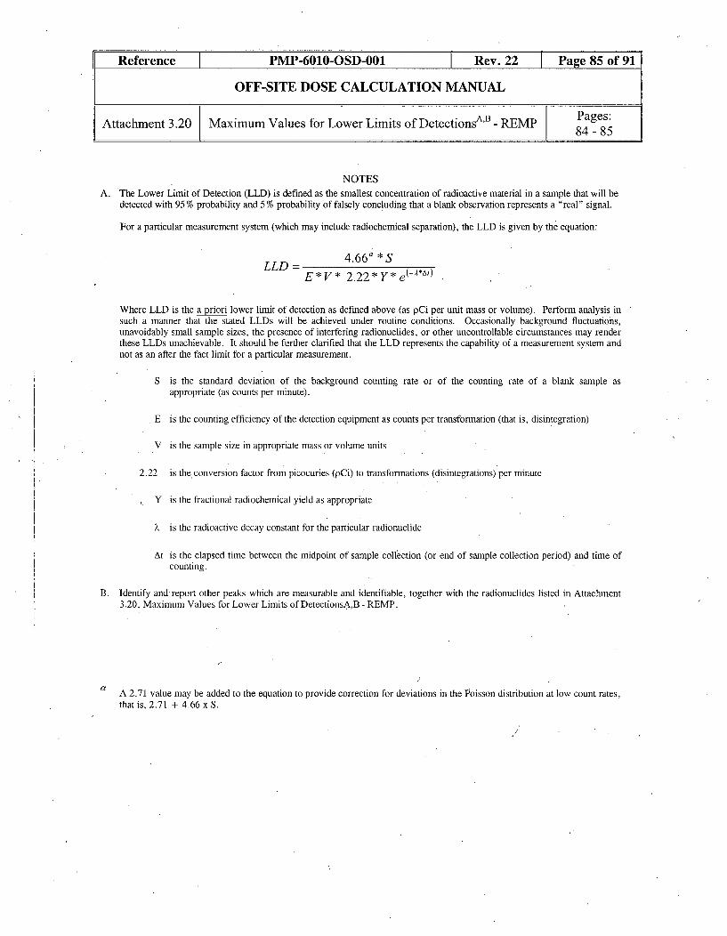
Reference PMP-6010-OSD-001 Rev. 22 Page 85 of 91
OFF-SITE DOSE CALCULATION MANUAL
Attachment 3.20 Maximum Values for Lower Limits of DetectionsAB REMP Pages:84 -8
NOTESA. The Lower Limit of Detection (LLD) is defined as the smallest concentration of radioactive material in a sample that will be
detected with 95% probability and 5% probability of falsely concluding that a blank observation represents a "real" signal.
For a particular measurement system (which may include radiochemical separation), the LLD is given by the equation:
LLD- 4.66a *SE*V* 2.22*Y*e(-*A!)
Where LLD is the a priori lower limit of detection as defined above (as pCi per unit mass or volume). Perform analysis insuch a manner that the stated LLDs will be achieved under routine conditions. Occasionally background fluctuations,unavoidably small sample sizes, the presence of interfering radionuclides, or other uncontrollable circumstances may renderthese LLDs unachievable. It should be further clarified that the LLD represents the capability of a measurement system andnot as an after the fact limit for a particular measurement.
S is the standard deviation of the background counting rate or of the counting rate of a blank sample asappropriate (as counts per minute).
E is the counting efficiency of the detection equipment as counts per transformation (that is, disintegration)
V is the sample size in appropriate mass or volume units
2.22 is the conversion factor from picocuries (pCi) to transformations (disintegrations) per minute
Y is the fractional radiochemical yield as appropriate
k is the radioactive decay constant for the particular radionuclide
At is the elapsed time between the midpoint of sample collection (or end of sample collection period) and time ofcounting.
B. Identify and report other peaks which are measurable and identifiable, together with the radionuclides listed in Attachment3.20, Maximum Values for Lower Limits of DetectionsA,B - REMP.
af
A 2.71 value may be added to the equation to provide correction for deviations in the Poisson distribution at low count rates,that is, 2.71 + 4.66 x S.

Reference PMP-6010-OSD-001 Rev. 22 Page 86 of 91
OFF-SITE DOSE CALCULATION MANUAL
Reporting Levels for Radioactivity Concentrations Page:Attachment 3.21 in Environmental Samples 86
Radionuclides Food Product Water Milk Air Filter FishpCi/kg, wet pCi/l pCi/l pCi/rn3 pCi/kg, wet
H-3 20000
Ba-140 200 300
La-140 200 300
Cs-134 1000 30 60 10 y 1000
Cs-137 2000 50 70 20 2000
Zr-95 400
Nb-95 400
Mn-54 1000 30000
Fe-59 400 10000
Zn-65 300 20000Co-58
Co-60
1000
300
2
3000010000
i -i ________________ -- F- ------F- --
1-131 100 3 0.90
IF any of the above concentration levels are exceeded THEN see guidance contained in step 3,5.2a. for additionalinformation.

Reference PMP-6010-OSD-001 Rev. 22 Page 87 of 91
OFF-SITE DOSE CALCULATION MANUAL
Attachment 3.22 On-Site Monitoring Location - REMP Page:87
ONS-South ONS-North Surface WaterTLD T-6 TLD T-5 SWL-3Air ONS- Air ONS-5 Surface Water Well W-6 Well Se6 SWL-2 r W_,eIi Sediment SL-3 Well
L I Sediment SL-2 '. 2 W9
LEGENDONS-1 - ONS-6: Air Sampling StationT-1 -T-12: TLD Sampling StationW-1 -W-17: REMP Groundwater WellsSWL- 2, 3: Surface Water Sampling StationsSL-2 SL-3: Sediment Sampling StationsONS-N & S: Fish samolino locations

Reference PMP-6010-OSD-001 Rev. 22 Page 88 of 91
OFF-SITE DOSE CALCULATION MANUAL
Attachment 3.23 Off-Site Monitoring Locations - REMP Page:88
LegendOffsite REMP Monitoring Locations
OFT-1 - OFT-11: TLD LocationsBackground Air/TLD StationsDrinking Water LocationsIndicator Milk Farm LocationsBackground Milk Farm LocationsOFS Offsite Fish locations
Hwy 23
Kankakee StationBackground
AirITLD(SBN)

Reference PMP-6010-OSD-001 Rev. 22 Page 89 of 91
OFF-SITE DOSE CALCULATION MANUAL
Attachment 3.24 Safety Evaluation By The Office Of Nuclear Pages:Reactor Regulation 89 - 91
SAFETY EVALUATION BY THE OFFICE OF NUCLEAR REACTOR REGULATIONRELATED TO DISPOSAL OF SLIGHTLY CONTAMINATED SLUDGE
INDIANA MICHIGAN POWER COMPANYDONALD C. COOK NUCLEAR PLANT, UNIT NOS. 1 AND 2
DOCKET NOS. 50-315 AND 50-316 [Ref. 5.2.1r]
(This is a 10 CFR 50.75 (g) item)
1. INTRODUCTIONBy letters dated' October 9, 1991, October 23, 1991, September 3, 1993, and September 29, 1993, Indiana MichiganPowerCompany (I&M) requested approval pursuant to 10 CFR 20.2002 for the on-site disposal of licensed material not previouslyconsidered in the Donald C. Cook Nuclear Plant Final Environmental Statement dated August 1973. Specifically, thisrequest addresses actions taken in 1982 in which approximately 942 cubic meters of slightly contaminated sludge wereremoved from the turbine room sump absorption pond and pumped to the upper parking lot located within the exclusion areaof the Donald C. Cook Nuclear Plant. The contaminated sludge was spread over an area of approximately 4.7 acres. Thesludge contained a total radionuclide inventory of 8.89 millicuries (mCi) of Cesium-137, Cesium-136, Cesium-134, Cobalt-60 and Iodine-131.
In its submittal, the licensee addressed specific information requested in accordance with 10 CFR 20.2002(a), provided adetailed description of the licensed material, thoroughly analyzed and evaluated information pertinent to the impacts on theenvironment of the proposed disposal of licensed material, and committed to follow specific procedures to minimize the riskof unexpected exposures.
2. DESCRIPTION OF WASTE
The turbine room sump absorption pond is a collection place for water released from the plant's turbine room sump. Thecontamination was caused by a primary-t0-secondary steam generator leak that entered the pond from the turbine buildingsump, a recognized release pathway. Sludge, consisting mainly of leaves and roots mixed with sand, built up in the pond.As a result, the licensee dredged the pond in 1982. The radioactive sludge removed by the dredging activities was pumpedto a containment area located within the exclusion area. The total volume of 942 cubic meters of the radioactive sludge thatwas dredged from the bottom of the turbine room absorption pond was subsequently spread and made into a graveled roadover the upper parking lot area of approximately 4.7 acres.
The principal radionuclides identified in the dredged material are listed below.
TABLE 1
NUCLIDE ACTIVITY (mCi) ACTIVITY (mCi)(half-life) 1982 1991
136
CS (13.2 d) 0.03 NA*'34Cs (2.1 y) 2.34 0.18
137Cs (30.2 y) 5.59 4.576 0Co (5.6 y) 0.90, 0.271311 (8.04 d) 0.03 NA*
TOTAL: 8.89 5.02
* NA: not applicable due to decay

Reference PMP-6010-OSD-001 Rev. 22 Page 90 of 91
OFF-SITE DOSE CALCULATION MANUAL
Safety Evaluation By The Office Of Nuclear Pages:Reactor Regulation 89-91
3. RADIOLOGICAL IMPACTS
The licensee in 1982 evaluated the following potential exposure pathways to members of the general public from theradionuclides in the sludge:
(1) external exposure caused by groundshine from the disposal site;
(2) internal exposure caused by inhalation of re suspended radionuclide;-AND-
(3) internal exposure from ingesting ground water.
The staff has reviewed the licensee's calculational methods and assumptions and finds that they are consistent withNUREG-1101, "Onsite Disposal of Radioactive Waste," Volumes 1 and 2, November 1986 and February 1987,respectively. The staff finds the assessment methodology acceptable. Table 2 lists the doses calculated by the licensee forthe maximally exposed member of the public based on a total activity of 8.89 mCi disposed in that year.
TABLE 2
Pathway Whole Body Dose Received byMaximally Exposed Individual
(mrem/year)
Groundshine 0.94
.Inhalation 0.94
Groundwater Ingestion 0.73
Total 2.61
On July 5, 1991, the licensee re-sampled the onsite disposal area to assure that no significant impacts and adverse effects hadoccurred. A counting procedure based on the appropriate environmental low-level doses was used by the licensee; however,no activity was detected during the re-sampling'. This is consistent with the original activity of the material and the decaytime. The 1991 re-sampling process used by the licensee confirms that the environmental impact of the 1982 disposal wasvery small. The staff finds the licensee's methodology acceptable.
4. ENVIRONMENTAL FINDING AND CONCLUSION
The staff has evaluated the environmental impact of the proposal to leave in place approximately 942 cubic meters of slightlycontaminated sludge underneath the upper parking lot on the Donald C. Cook Nuclear Plant site.
In 1982, the licensee evaluated the potential exposure to members of the general public from the radionuclides in the sludgeand calculated the potential dose to the maximally exposed member of the public, based on a total activity of 8.89 mCidisposed in that year, to be 2.61 mrem/yr. The staff has reviewed the licensee's calculational methods and assumptions andfound that they are consistent with NUREG-1 101, Onsite Disposal of Radioactive Waste, Volumes 1 and 2, November 1986and February 1987, respectively. The staff finds the assessment methodology acceptable. For comparison, the radiationfrom the naturally occurring radionuclides in soils and rocks plus cosmic radiation gives a person in Michigan a whole-bodydose rate of about 89 mrem per year outdoors. Subsequent licensee sampling in 1991 identified no detectable activity. Thestaff evaluated the licensee's sampling and analysis methodology and finds it acceptable. The results, of the 1991 re-sampling by the licensee, confirm that the environmental impact of the 1982 disposal was very small.
Based on the above the staff finds that the potential environmental impacts of leaving the contaminated sludge in place areinsignificant. With regard to the non-radiological impacts, the staff has determined that leaving the soil in place representsthe least impact to the environment.

Reference PMP-6010-OSD-001 Rev. 22 Page 91 of 91
OFF-SITE DOSE CALCULATION MANUAL
Attachment 3.24 Safety Evaluation By The Office Of Nuclear Pages:Reactor Regulation 89 - 91
5. CONCLUSION
Based on the staff's review of the licensee's discussion, the staff finds the licensee's proposal to retain the material in itspresent location as documented in this Safety Evaluation acceptable. Also, this Safety Evaluation shall be permanentlyincorporated as an appendix to the licensee's Offsite Dose Calculation Manual (ODCM), and any future modifications shallbe reported to NRC in accordance with the applicable ODCM change protocol.
I&M letter from E. E. Fitzpatrick to the NRC Document Control Desk, September 29, 1993
Therefore, the licensee's proposal to consider the slightly contaminated sludge disposed by retention in place in the mannerdescribed in the Donald C. Cook Nuclear Plant submittals date October 9, 1991, October 23, 1991, September 3, 1993, andSeptember 29, 1993, is acceptable.
The guidelines used by the NRC staff for onsite disposal of licensed material and the staff's evaluation of how each guidelinehas been satisfied are given in Table 3.
Pursuant to 10 CFR 51.32, the Commission has determined that granting of this approval will have no significant impact onthe environment (October 31, 1994, 59 FR 54477).
Principal Contributor: J. Minns
Date: November 10, 1994
TABLE 3
20.2002 GUIDELINE FOR ONSITE STAFF'S EVALUATION
DISPOSAL2
1, The radioactive material should be disposed of in such 1. Due to the nature of the disposed material, recycling to thea manner that it is unlikely that the material would be general public is not considered likely.recycled.
2. Doses to the total body and any body organ of a 2. This guideline was addressed in Table 2. Although themaximally exposed individuals (a member of the 2.61 mrem/yr is greater than staff's guidelines, the staffgeneral public or a non-occupationally exposed worker) finds it acceptable due to 9 yrs decay following analysis andfrom the probable pathways of exposure to the disposed the expected lack of activity detected in the 1991 survey.material should be less than 1 mrern/year.
3. Doses to the total body and any body organ of an 3. Because the material will be land-spread, the staff considersinadvertent intruder from the probable pathways of the maximally exposed individual scenario to also addressexposure should be less than 5 mrem/year. the intruder scenario.
4. Doses to the total body and any body organ of an 4. Even if recycling were to occur after release from regulatoryindividual from assumed recycling of the disposed control, the dose to a maximally exposed member of thematerial at the time the disposal site is released from public is not expected to exceed 1 mrem/year, based onregulatory control from all likely pathways of exposure exposure scenarios considered in this analysis.should be less than 1 mrem.
, E: F. Branagan,. Jr. and F. J. Congel, "Disposal of Contaminated Radioactive Wastes from Nuclear Power Plants,"
presented at the Health Physics Society's Mid-Year Symposium on Health Physics Consideration inDecontamination/Decommissioning, Knoxville, Tennessee, February 1986, (CONF-860203).

REVISION SUMMARY
Procedure No.: PMP-6010-OSD-001Title: OFF-SITE DOSE CALCULATION MANUAL
Rev. No.: 22
Alteration Justification
10 CFR 50.59 is not applicable to this Per definition in Attachment 1 of PMP-2010-procedure revision. PRC-002. This is an administrative
procedure governing the conduct of facilityoperations. Changes to this document aremade in accordance with TechnicalSpecification 5.5.1 and implemented through12-EA-6090-ENV- 114, EffectivenessReview for ODCM/PCP Programs.
3.1. 1 c, item Qi altered procedure number This corrects a typographical error asfrom 606 to 601 to correct typo. evidenced by the correct procedure title
listed is for RPP-601. This meets editorialcorrection criteria (ECC) 1.
3.5.2a.6.c, added the clarifying words 'when This is clarifying information sincevegetation is available' to the step. vegetation is not available year round and
can only be collected when available. Thisis documented in AR 808291. This meetsECC p.
Deleted section 3.6 that discussed This-was deleted since it refers to 'data ornly'Mausoleum groundwater monitoring samples and is not part of the REMP andprogram. Renumbered remaining steps. was directed as part of AR 128023
evaluation. The SG wells were also deletedfrom the map, Attachment 3.22. Thelocations had previously been removed fromAttachment 3.19. This information currentlyresides in 12-THP-6010-RPP-634 for thesewells. This meets ECC p.
Added clarifying Wording to * footnotes in This was the result of the evaluationboth Attachment 3.3 and 3.5 to denote that associated with AR 810352 that concludedthis applies to all of the surveillances to the that maintaining the blowdown treatmentappropriate instrument, not just the channel radiation monitor in operational readinesscheck. was low value work and need not be
maintained. Operations concurred with thisdeviation from the 'full deck' philosophy.This meets ECC p.
Office Information for Form Tracking Only - Not Part of FormThis is a free-form as called out in PMP-2010-PRC-002, Procedure Alteration, Review, andApproval. Page 1 of 2

REVISION SUMMARY
Procedure No.: PMP-6010-OSD--(51
Title: OFF-SITE DOSE CALCULATION MANUALRev. No.: 22
Alteration Justification
Added groundwater (well water) sample Two additional wells, former NPDES wellsstations W-16 and W-17 to Attachment 3.19 designated MW-20 and MW-21, were addedand Attachment 3.22. to the REMP as part of the "D. C. Cook
Nuclear Plant Groundwater ProtectionProject Charter" to more closely monitorgroundwater flow characterized by the planthydrology study. This change was done inresponse to AR 807643 evaluation.
Attachment 3.19 Reduced the spaces for NUREG-1301, Offsite Dose CalculationIngestion - Milk Background Farm from two Manual Guidance- Standard Radiologicalto one and dropped farm to singular instead Effluent Controls for Pressurized Waterof plural. Changed * footnote from two Reactors, Table 3.12-1, REMP, onlybackground farms to one also. Correctly requires one control (background) location.formatted conditional if, then statement.
Reformatted map in Attachment 3.23 since it Map did not electronically transferdid not transfer well electronically during completely during the last revision. Thisrevision 21. No changes were made to this meets ECC j and 1. It is the same mapmap. presented inrevision 20 of PMP-6010-OSD-
001. No changes, were made during the pasttwo revisions of this document. AR 808170documents this.
Office Information for Form Tracking Only - Not Part of FormThis is a free-form as called out in PMP-2010-PRC-002, Procedure Alteration, Review, andApproval. Page 2 of 2