of a rocky residual soil l
TRANSCRIPT

L L
L
L
MISSOURI COOPERATIVE HIGHWAY RESEARCH PROGRAM
FINAL REPORT
STRENGTH AND DRAINAGE PROPERTIES OF A
ROCKY RESIDUAL SOIL
MISSOURI STATE HIGHWAY DEPARTM

1

l L L L L L L
L L L
L J
r L
l L L r
STRENGTH AND DRAINAGE PROPERTIES OF A ROCKY RESIDUAL SOIL
STUDY NO. 75-1
Prepared by
MISSOURI STATE HIGHWAY DEPARTMENT
Division of Materials and Research
Final Report March 1976
in cooperation with
U.S, DEPARTMENT OF TRANSPORTATION
Fede ral Highway Administration
The opinions, findings, and conclusions expressed in this publication are not necessarily those or the Federal H.ighway Administration.

l l l l L L l l L l L
l L l L L L
-
ABSTRACT
The quantity of granular material in a Clarksville residual clay was varied to
determine the effect on strength parameters as determined by triaxial test procedures.
Consolidation and permeability characteristics were also studied. Some general conclusions
are drawn on the relationship of granular rootent to permeability and pore pressure
development in embankment construction.

,-

L
L L L l L L r ~
f
~
L ,
•
I L
,
l
Introduction
Conclusions
Implementation
Scope
The Study Soil
Preparation and
Analysis of Data
TABLE OF CONTENTS
Testing
2
3
4
5
8
10

LIST OF FIGURES
Figure
I. Compaction Curves for Clarksville Gravelly Clays
2. Gradations of Natural Clarksville Gravelly Oays
3. Gradations of Mixtures Prepared for Triaxial Testing (2.75 Inch Diameter)
4. Consolidation Curves for 2.75 Inch Diameter Triaxial Specimens at 60 psi Lateral Pressure
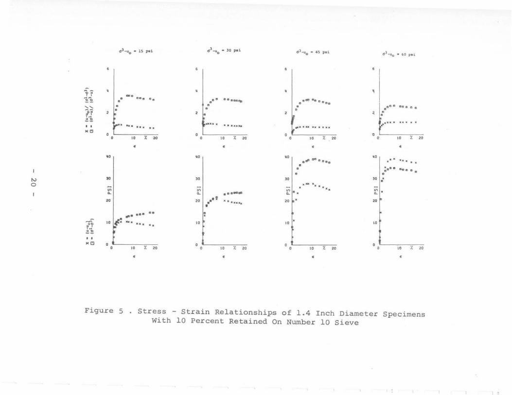
5. Stress - Strain Relationships of 1.4 Inch Diameter Specimens with 10 Percent Retained on Number 10 Sieve
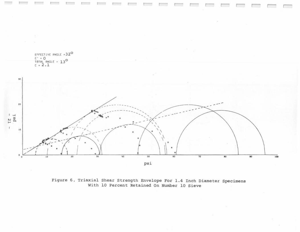
6. Triaxial Shear Strength Envelope for 1.4 Inch Diameter Specimens with 10 Percent Retained on Number 10 Sieve
7. Stress - Stress Relationships of 1.4 Inch Diameter Specimens with 20 Percent Retained on Number 10 Sieve
8. Triaxial Shear Strength Envelope for 1.4 Inch Diameter Specimens with 20 Percent Retained on Number 10 Sieve
9. Stress - Strain Relationships of 1.4 Inch Diameter Specimens with 25 Percent Retained on Number 10 Sieve
10. Triaxial Shear Strength Envelope for 1.4 Inch Diameter Specimens with 25 Percent Retained on Number 10 Sieve
II. Stress· Strain Relationships of 1.4 Inch Diameter Specimens with 30 Percent Retained on Number 10 Sieve
12. Triaxial Shear Strength Envelope for 1.4 Inch Diameter Specimens with 30 Percent Retained on Number 10 Sieve
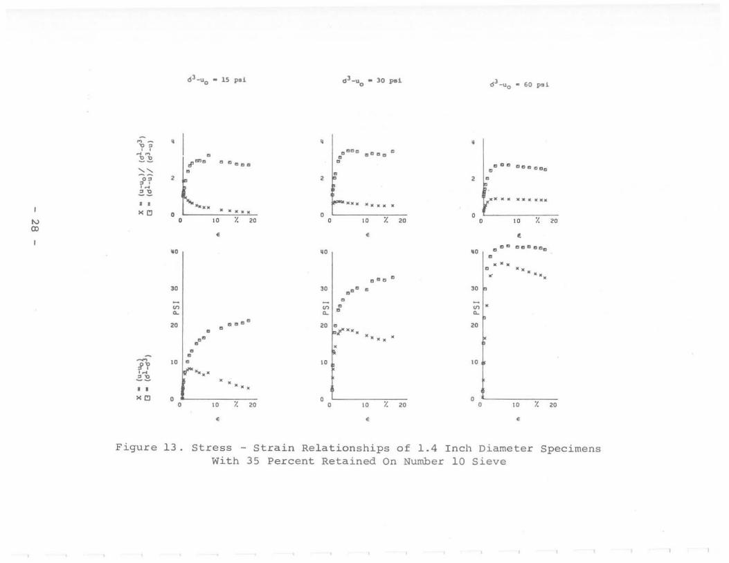
13. Stress· Strain Relationships of 1.4 Inch Diameter Specimens with 35 Percent Retained on Number 10 Sieve
14. Triaxial Shear Strength Envelope for 1.4 Inch Diameter Specimens with 35 Percent Retained on Number 10 Sieve
IS. Stress· Strain Relationships of 1.4 Inch Diameter Specimens with 40 Percent Retained on Number 10 Sieve
16. Triaxial Shear Strength Envelope for 1.4 Inch Diameter Specimens with 40 Percent Retained on Number 10 Sieve
6
7
9
13
20
21
22
23
24
2S
26
27
28
29
30
31

L [ Figure Page
L 17. Stress - Strain Relationships of 2.0 lnch Diameter
Specimens with 20 Percent Retained on Number 10 Sieve 32
18. Triaxial Shear Strength Envelope for 2.0 Inch Diameter
l Specimens with 20 Percent Retained on Number 10 Sieve 33
19. Stress - Strain Relationships of 2.0 Inch Diameter
l Specimens with 25 Percent Retained on Number 10 Sieve 34
20. Triax ial Shear Strength Envelope for 2.0 Inch Diameter
[ Specimens with 25 Percent Retained on Number 10 Sieve 35
2l. Stress - Strain Relationships of 2.0 Inch Diameter Specimens with 30 Percent Retained on Number 10 Sieve 36
L 22. Triaxial Shear Strength Envelope for 2.0 Inch Diameter Specimens with 30 Percent Retained on Number 10 Sieve 37
l 23. Stress - Strain Relationships of 2.0 Inch Diameter Specimens with 35 Percent Retained on Number )0 Sieve 38
l 24. Triaxial Shear Strength Envelope for 2.0 Inch Diameter Specimens with 35 Percent Retained on Number 10 Sieve 39
l 25. Stress - St rain Relationships of 2.0 Inch Diameter Specimens with 45 Percent Retained on Number 10 Sieve 40
[ 26. Triaxial Shear Strength Envelope for 2.0 Inch Diameter
Specimens with 45 Percent Retained on Number 10 Sieve 41
27. Stress - Strain Relationships of 2.75 Inch Diameter
l Specimens with 10 Percent Retained on Number 10 Sieve 42
28. Triaxial Shear Strength Envelope for 2.75 Inch Diameter
[ Specimens with 10 Percent Retained on Number 10 Sieve 43
29. Stress - Strain Relationships of 2.75 Inch Diameter
l Specimens with 20 Percent Retained on Number 10 Sieve 44
30. Triaxial Shear Strength Envelope ror 2.75 Inch Diameter Specimens with 20 Percent Retained on Number 10 Sieve 45
l 31. Stress - Stra in Relationships of 2.75 Inch Diameter Specimens with 25 Percent Retained on Number 10 Sieve 46
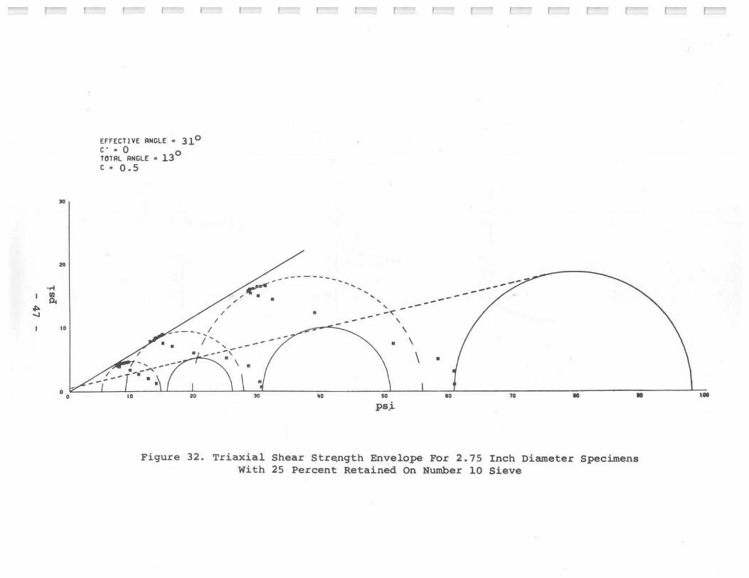
l 32 Triaxial Shear Strength Envelope for 2.75 Inch Diameter Specimens with 25 Percent Retained on Number 10 Sieve 47
L 33. Stress - Stra in Relationships of 2.75 Inch Diameter Specimens with 30 Percent Retained on Number 10 Sieve 48
l {

Figure Page
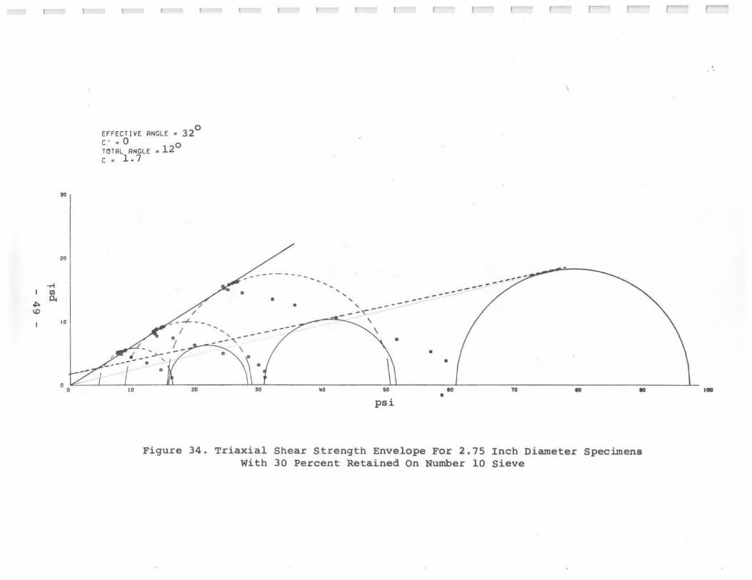
34. Triaxial Shear Strength Envelope for 2.75 Inch Diameter Specimens with 30 Percent Retained on Number 10 Sieve 49
35. Stress - Strain Relationships of 2.75 Inch Diameter Specimens with 35 Percent Retained on Number IO Sieve 50
36. Triaxial Shear Strength Envelope for 2.75 Inch Diameter Specimens with 35 Percent Retained on Number 10 Sieve 51
37. Stress - Strain Relationships of 2.75 Inch Diameter Specimens with 40 Percent Retained on Number 10 Sieve 52
38. Triaxial Shear Strength Envelope for 2.75 Inch Diameter Specimens with 40 Percent Retained on Number 10 Sieve 53
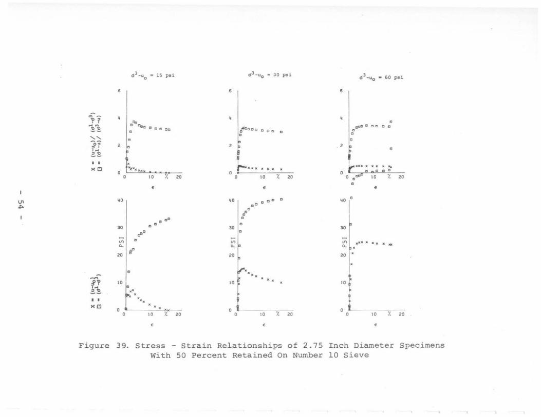
39. Stress - Strain Relationships of 2.75 Inch Diameter Specimens with 50 Percent Retained on Number 10 Sieve 54
40. Triaxial Shear Strength Envelope for 2.75 Inch Diameter Specimens with 50 Percent Retained on Number 10 Sieve 55

LIST OF TABLES
Table
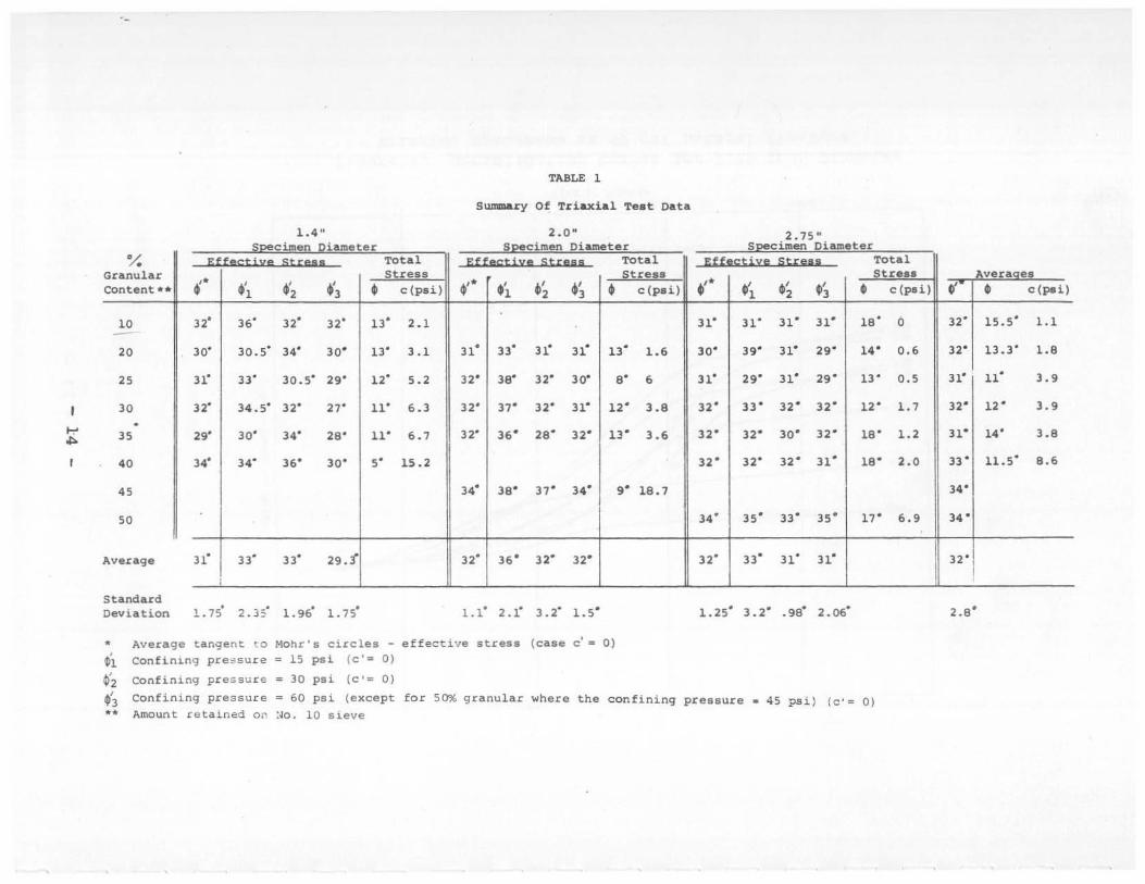
l. Summary of Triaxial Test Data
2. Summary of Permeability Test Data Determined by One~Dimensional Consolidation Tests
3.
4.
5.
6.
Averages of Pore Granular Content
u-u Pressure Factor 1 ~
6 -6 vs. Varying
d1-u Effective Stress Factor 3 vs. Varying Granular
6 - u Content for 1.4 Inch Diameter Triaxial Specimens
cj l_u Effect ive Stress Factor 6 3 'IS. Varying Granular
-u Content for 2 Inch Diameter Triaxial Specimens
1 Effect ive Stress Factor 6 j -u vs. Varying Granular
d -u Content, 2. 75 Inch Diameter Triaxial Specimens
14
15
16
17
18
19

c
c'
" "0
LIST OF ABBREVIATIONS AND SYMBOLS
apparent cohesion (y intercept of MOhr's total stress strength envelope)
cohesion (y intercept of Mohr's effective stress strength envelope)
change in height
consolidated undrained triaxial test with pore pressure measurements
total pore pressure
pore pressure resulting from 6 3 confining pressure
induced pore pressure during shear
strain
angle of internal friction based on total stress
angle of internal friction based on effective stress
effective angle of internal friction based on deviator
effective angle of internal friction based on deviator
effective angle of internal friction based on deviator
stress
stress
stress
deviator stress (total axial stress minus confining pressure)
of 15 psi
of 30 psi
of 60 psi

J
INTRODUCTION
Many of the highest roadway fiUs in Missouri are constructed of residual clays
from the Clarksville series which contain varying amounts of admixed chert ranging in
size from sand to boulders. Slope designs for such high fills have been based on experience
gained from fills of lesser heights. Equipment restrictions have limited previous
consolidation and direct shear testing to samples with the granular fraction larger than
sand size removed.
In a previous research report entitled Moisture, Density and Slope Reguirements
in High Fills, it was concluded that such soi ls, when encountered without significant
granular content, should be limited by stability considerations to about 40 feet in height
with 2 to I slopes. This conclusion was based upon interpretation of direct shear tests
of essentially granular free soil. However, it was acknowledged that , since granular-free
occurrences were rare, such slope and height restrictions were inconsistent with
demonstrated performance of the normal occurrences of the soil. The present study was
designed to overcome these limitations and to develop data on strength, consolidation
and permeability characteristics of the soil with granular contents more typical of normal
occurrences. It was concluded that triaxial testing was the most practical means of
achieving these objectives for this soil.
- 1 -

CONCLUSIONS
1. With less than about 40 percent retained on the No. 10 sieve, the study
soil was indicated by triaxial tests to have an effective angle of internal friction averaging
32 degrees. The average effective angle increased to a maximum of 34 degrees with 50
percent granular content, the maximum tested.
Total strength parameters show a large increase in apparent cohesion at granular
contents exceeding 40 percent.
2. Triaxial and consolidation test data indicate the study soil to be highly
impermeable at granular contents of less than about 40 percent. At granular contents
over 40 percent, the permeability increases as much as fifty fold.
3. Triaxial testing, while slow and expensive, is judged to provide more realistic
strength parameters than were previously determined by direct shear testing for this soil
Similar testing would appear appropriate for any other gravelly soil to be used in
embankments of such height that stability problems could be likely or of serious
consequences should they occur.
4. Within the ranges tested, no significant differences in effective strength
parameters were found as a result of varying triaxial specimen sizes or the top size of
the included granular material
- 2 -

I L.
L L L L L L
f L
L L L L L
IMPLEMENTATION
Consideration should be given to requiring detennination during the soil survey
of the granular content of residual clays. This would be most useful in design of fills
built of such soils. A determination that the granular content exceeds about 40 percent
would suggest free drainage, rapid settlement and minimal stability problems. Those soils
with granular contents less than about 40 percent should receive specia l consideration
of settlement and stability problems where embankment heights exceed about 40 feet,
the limitation suggested by a previous study of this soil with minimal granular content.
Triaxial shear parameters, in the light of past experience, appear to provide a
realistic basis for predicting behavior of gravelly clay residual soils. As most of the residual
soil series in Missouri usually have high granular content, triaxial testing should be used
in future studies of slope requirements for high fiUs of such soils.
Both experience and the data derived in this study confirm that steeper fill
slopes are practical with such gravelly residual soils than are possible with most other
soils in the state.
- 3 -
SCOPE
A residual gravelly clay commonly encountered in heavy grading for highway
embankments in southern Missouri was modified with varying amounts of granular material
from a minimum of 10% to a maximum of 50% retained on the No. 10 sieve. These
varying mixtures were tested for determination of shear strength, consolidation and
permeability characteristics.
Triaxial test specimens were graded to match natural gravelly clays, statically
compacted wet of optimum and back pressured to saturation. Shear tests were performed
by consolidated, undrained (R) procedures to permit evaluation of both effective and total
stresses.
Specimen sizes of 1.4 inch, 2 inch and 2.75 inch diameters, with varying sizes
of gravel added. were tested for evaluation of the effect of top size and gradation of
the granular fraction.
Permeability data derived from both triaxial and consolidation tests was evaluated
to determine the granular content at which internal drainage would permit rapid
consolidation and dissipation of pore pressures.
- 4 -

l l L L L L L L l L L L I L
l L
TIlE STUDY SOIL
The study soil is a residual clay from the Oarksville series derived from the
decomposition of cherty dolomitic limestones. It is found throughout the Ozark Region
of southern Missouri. The soil sample used in the study is from Route 21 in Reynolds
County and was used in a previous study entitled Moisture, Density and Slope Requirements
of High Fills. It is relatively free of granular content with 10 percent retained on the
No. 10 sieve and 78 percent passing the No. 200 sieve. As sampled, it is non-typical
for the series although representative of chert free pockets frequently encountered. A
liquid limit of 69 and a plastic limit of 41 were determined. Soils of this series arc
found with a liquid limit range of 25 to 85 and a plastic index range of 9 to 54.
Compaction records from past projects show Clarksville series clays to exhibit
a wide range in granular contents and maximum densities. Typical compaction curves
and gradations are shown in Figures I and 2. In Figure I , Group A represents 6 samples
having less than 40 percent passing the No. 200 sieve and Group B 16 samples having
between 40 and 60 percents passing the No. 200 sieve. As these curves wouJd suggest,
considerable difficulty is experienced in construction control since the applicable maximum
density varies widely with the amount , size and specific gravity of the granular fraction.
Frequently the chert content is such that the soil is judged "too rocky to test" by
inspectors.
The known range of specific gravity of the admixed chert varies from 1.85 to
2.65. That added in preparation of test specimens had a specific gravity of 2.26 and
was composed of typical angular fragments obtained by washing of natural Clarksville
gravelly clay mixtures.
- 5 -

,e>
I
--~ " , , " •
u
"
u,
'"
..
,
~
~ Gcoup A
<. 401t. p"' .. i"9 n_< 100 .hwe
" " " .. " '" " ""'inure Conunt
Figure 1.
uo
C<O"P a
< 60l' but) 40% """'''9 the n"-" 200 .tev.
u, ---~ ; ] • , '"
a-.... ..
.. " " .. " •
" Moi.nuu CD"...,.
compaction Curves for Clarksville Gravelly Clays
o
~
" "

,
-.J
'F I 10
, ,
"" " -;;
I : ~
;., I " • o
• :< ! ~
I I "II iT )
IIII ' '
1m
... 100
II Tn
1\
~~ ~ R III III ~ -..: 111
AV·~.!1e ---=
~ "-
"W
III III Ii .. 10 . 1
Size l.n 111m
Figure 2. Gradation of Natural Clarksville Gravelly Clays
..
-

PREPARATION AND TESTING
Gravel and clay mixtures were prepared with the amounts retained on the No.
10 sieve varied in increments of 5 percentage points from 10 to 50 percent. Additional
fine granular content was added to produce gradations approximating natural Clarksville
soils as closely as the maximum allowable particJe sizes would permit. (See Figure 3.)
The maximum particle size was limited to that passing the 1/4 inch sieve and retained
on the No.4 for 1.4 inch and 2 inch diameter triaxial test specimens, and to that passing
the 3/8 inch and retained on the 1/4 inch sieve for the 2.75 inch diameter specimen.
The resulting gradation curves for the 2.75 inch diameter specimens are shown in Figure
3.
Test specimens were statically compacted to the maximum extent practical on
the wet side of optimum to obtain a nearly saturated specimen at approximately 95 percent
of AASHTO T-99 maximum density for the soil fraction only (less the admixed granular
portion). Thirty-three percent moisture was added based on weight of the soil less the
admixed granular portion. The granular material was soaked for 24 hours, drained and
blotted free of water before blending. All mixtures were cured 24 hours after adding
water and before compaction. Triaxial specimens were prepared in 1.4 inch, 2 inch and
2.75 inch diameters, all having a 2 to I height to diameter ratio. Consolidated, undrained
triaxial tests with pore pressure measurements (R) were performed in conformance with
AASHTO T-234-70 except that the ratio of specimen diameter to maximum particle size
was about 7 to I instead of 10 to I for the 1.4 inch diameter specimens.
Differential confining pressures varied from 15 to 60 psi. Porous stones were
used at both end caps with discontinuous ftIter strips to facilitate saturation by
backpressuring in 5 psi increments with a 3 psi differential maintained across the membrane.
Pore pressures were monitored using low displacement transducers. Saturation was
considered complete when an immediate resp:mse in pore pressure was measured by the
transducer after an increase in back pressure.
Consolidation was measured by both changes in the heights of the specimens
and changes in burette readings with drainage.
Rate of shear was less than 0.002 inch per minute except that a rate of 0.0027
inch per minute was used with the 2.75 inch diameter specimens to permit achieving
15 percent strain in a normal work period encompassing 9 hours.
Membrane puncture by the sharp chert particles limited successful testing to
40 percent retained on the No. IO sieve for 1.4 inch diameter specimens, to 45 percent
for the 2 inch specimens and to 50 percent for the 2.75 inch specimens. Forty-five
- 8 -
,
•

L
l L L L L L
•
psi was the maximum differential confming pressure successfully applied to the 2.75 inch
diameter specimens with 50 percent retained on the No. J 0 sieve.
Triaxial test data was resolved by a computer program with automatic plotting
of Mohr's circles and stress-strain data.
Specimens with 20,30 and 45 percent retained on the No. 10 sieve were statically
molded to one inch thickness for consolidation testing, with moisture content and density
similar to that of the triaxial test specimens, for determination of permeability.
•• , - , .
~. ::1+J-H±+--= t r--.::mt ~:,"~~4-~~~~~~~,
-'"
• ~~~~mtt++~#H~'n" , ""~~p-
1 fIl.I-I+H-+-H+I+H-H
"~~~~H-~+H_III~I4-~H+_1
Figure 3. Gradation of Mixtures Prepared For 2.75 Inch Diameter
Triaxial Specimens
- 9 -
ANALYSIS OF DATA
General
Results of triaxial tests are presented as Figures 5 through 40. Mohr's circles
and plots of stress-strain relationships are included as alternate figures. Angles of effective
and total stress envelopes for varying granular contents and specimen sizes are summarized
in Table I. Both averages and standard deviations are also listed. Tabulation of stress-strain
relationship factors for varying granular contents and specimen sizes are presented on Tables
3, 4, 5 and 6.
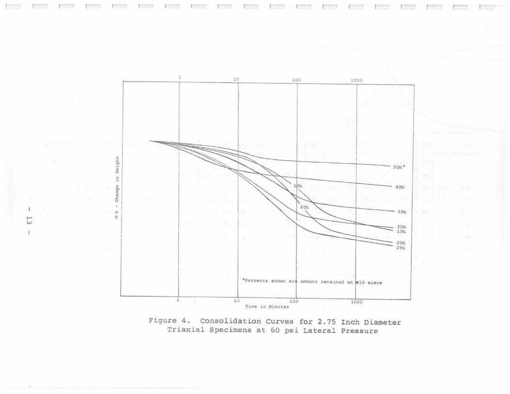
Consolidation curves obtained during conditioning of 2.75 inch diameter triaxial
specimens with varying granular contents are shown on Figure 4.
A summary of permeabilities computed from one dimensional consolidation tests
performed with varying granular contents are shown in Table 2.
In the following discussion, "granuJar content" is used to mean that portion
retained on the No. I 0 sieve.
Effective Stresses
The effective angle of internal friction ($') varies from 29 degrees to 34 degrees
for the 1.4 inch diameter triaxial specimens over a range of I 0 to 40 percent granular
content. $' varies from 31 to 34 degrees for the 2 inch diameter specimens over a range
of 20 to 45 percent granular content and from 30 to 34 degrees for the 2.75 inch diameter
specimen over a range of 10 to 50 percent granular content.
Also tabulated on Table I are the effective angles (~') determined by striking
lines tangent to individual Mohr's circles back to zero. The angles determined for 15
psi confrning pressures are highly variable, probably due to the apparent pre-consolidation
resulting from sample preparation. At confining pressures of 30 and 60 psi , the average
angle is 30.9 degrees with granular content of less than 40 percent and 33.5 degrees with
granuJar contents of 40 percent or greater.
Comparison of the effect of confining pressure on ~' indicates a consistent
variation. With granular contents of less than 40 percent, the average angles are 31.6
degrees for 30 psi confining pressures and 30.2 degrees at 60 psi. For granular contents
of 40 percent or greater, the averages are 34.5 degrees at 30 psi and 32.5 degrees at
60 psi. This average 1.5 degree variation as a function of confining pressure is believed
due to apparent pre-consolidation effects at the lower confining pressures and, at higlter
pressures, to development on the shear plane of locally high pore pressures which cannot
be accurately measured at the specimen ends.
The average angle (~') is 31.8 degrees for all tests at granular contents of less
than 40 percent. For 40 percent granular content, ~' is 32.5 degrees and, for 45 and
- 10 -

50 percent combined, the average is 35.3 degrees. The standard deviations of the test
results are 2.7, 2.2 and 1.9 degrees respectively.
Total Stresses
Comparison of total stress envelopes indicates the available shear resistance of
varying granular contents. The total stress strength increases dramatically at 40 percent
granular content with an average increase in apparent cohesion (c) of 7.7 psi. The total
stress angle (Itl) averages 12.5 degrees, apparently without significant variation as a function
of granular content. More varia tion is evident as a function of test specimen size with
2.75 inch diameter specimens indicating an average value of Ib of 4.9 degrees grea ter than
was determined for 1.4 inch specimens.
The increase in total stress occurring at approximately 40 percent granular
content and above is believed due to internal pressure dissipation within the shear plane
from dilatancy and to pressure equalization within the specimen as a function of the
greatly increased permeability.
Triaxial Stress-Stra in Related Factors
Factor U llO is the ratio of the internal pore pressure measured to the d l -d3
added axial load applied to the specimen. This factor , included in the plots in alternate
Figures 5 through 39, averages 0.8 to 1.0 through the 0 to 30 percent granu lar range
but, significantly, drops as low as 0.3 for tests on specimens where granular content exceeds
about 40 percent. At the higher contents, dilatancy effects are probably tending to relieve
internal pore pressures
The factor
at the shear plane in combination with increased permeability.
d~-U is the ratio of the effective axial load to the effective 6 -u
confining load on the specimen. Plots of this factor are included in alternate Figures
5 through 39, for varying specimen sizes. There are no significant patterns to the variations
of this factor throughout the range of tests. This suggests that rate of shear, drainage
and monitored pressures are not significant variables through the range of specimen sizes
and granular contents tested.
Permeability
Permeability data, obtained from consolidation tests on specimens with varying
granular content, are tabulated on Table 2. The permeabilities shown are calculated from
coefficients of consolidation and compressibility and from compression indices derived
from one-dimensional consolidation tests.
This data shows the permeability of the specimen with 45 percent retained on
the No. to sieve t.o have a 50 fold increase in permeability over a sample having 30
percent retained on the No. 10 sieve.
- 11 -

Time curves, plotted from consolidation of 2.75 inch diameter triaxial specimens
at varying granular contents, are shown in Figure 4. Due to the complex drainage and
indeterminate time factors associated with use of discontinuous filter strips, coefficients
of consolidation were not calculated. However. a comparison of these curves indicates
that the time for 50 percent consolidation, which is inversely proportionate to the
coefficient of consolidation, decreases as the percent granular content increases. At 40
percent granular content, the time for 50 percent consolidation is in the one to ten minute
range as compared to 50 minutes for specimens with lower granular content. This
corresponds to the changes in permeability computed from consolidation data.
All data and observations indicate that at about 40 percent granular content,
a substantial increase occurs in permeability.
,
- 12 -
• 0 .~, .' • " .• • I ~ ,
5J , I
0 , .... • w
I
, " ". 1000
~I """"" ,,,,,-
"" ~ 'P" .""
"" "'-t"~ ""- ,,.
''''' ''''' ''''' ,,.
· Pe r cente snown sr. amount retalned on ~lO aieve
, " , .. 1000
Tl:ne in Minut ••
Figure 4. Consolidation Curves for 2.75 Inch Diameter Triaxial Specimens at 60 psi Lateral Pressure
r
.,. ...
-.
X G.ranular Content ••
10 -20
" 30
,
" 40
45
50
Average
S tandard Deviation
1.4~
SpecilDen Oialll'te, Effective Stre •• Total
Strel. ," · '1 ~2 .'3 0 c{psi)
,,' 3.' ,,' ,,' ll' 2-1
30' 30.5' 34' 30' ll' 3_1
31' ,,' 30.5' 29' ,,' 5,2
,,' 34.5' '" ,,' 11' ._3
,.' 30' 34' '0' 11' .,7
34' 34' 3.' 30' 5' 15.2
31' ,,' 33' 29.f
, 1. 75" 2 . )3' 1.96' 1. 75'
TABLE 1
S~&y Of Triaxial Teat D&t&
2.0 · S2!c~men Dl&meter
EfCectiye Strel' Total
.," .'1 .~ ., ~tre ••
• c(pai)
31' ,,' 31' 31' ll' 1..
,,' 30' ,,' 30' 0' • '" 37' '" 31' 1" 3,0
,,' 3.' '0' ,,' ll' 3,'
34' 30' 37' 34' g' 18.7
,,' 3" ,,' '" 1.1' 2.1' 3.2' loS'
" Aver age tangent to Mohr's circle, e f f ective stre •• (ca s e c' - OJ ~'1 Confi nlng p ressur e 15 pli (c'· 0) ., Confining p r essu r e • 30 pai (c'· 0)
2.75 · S2!clmen Qlam.ter
Effectiye Stre •• Total ;tr, ..
.," ,'1 O~ " • c (ptli)
31' 31' 31' 31' 10' 0
30' 3.' 31' 2.' 14' 0,.
31' 29' 31' 2.' ll' 0,5
,,' 33' '" '" '" 1.7
,,' ,,' 30' ,,' 10' 1.2
'" '" '" 31' lB' 2-0
34' ,,' ,,' ,,' 17' .,. ,,' 33' 31' 31'
1.25' 3.2' .98" 2 . 06"
"3 Conf i n ing pressure - 60 ps i {except for 50% g ra nu lar whe Le the confining pre •• ure • 45 psi ) (c ' . 0)
"" Amoun t retained on :.0 . 10 lieve
Aver' e. 0' 0 c(pd)
,,' 15.5' 1.1
,,' 13.3' 1.0
31' 11' 3,.
'" '" 3_.
31' 14' 3,0
,,' 11.5" 0,'
34'
34 '
'" 2 . 8"

• r-
.... '"
r- r- r- r- r'- , r- r- r- r- r- r- r- r-
Summary of
Granular Content·
",,. 20%
30%
45"
TABLE 2
Permeability Data Determined Consolidation Tests
Coefficient of Con!olidation .. r~ /O_ay x 10-2
2
1.5
1.5
60
*Amount reta i ned on No. 10 sieve **4 . a and 16 Taf loading average
.**At 4 ton loading in consolidometer
by One-Dimensional
Permeabi 11 ty ••• X10:-:'~ ,_~~
7.5
5.9
4.7
250
r- r- r- r-

.... '"
TABLE )
Averages Of Pore Pressure Factor (u-Uo) Va. Varying Granular content
(0'1-1$')1
% Granular Content*
10' 20 25 )0 JS
(1" 1 - 0') At )ox; Strain
15 psi .925 .94 . 89 ." .0)
)0 psi .925 .90 1.0 .87 .80
60 psi 1.025 1.08 1.1 1.11 .9
At 8% Strain
15 psi .81 .79 .0' .44 .44
30 psi .8 .91 .81 .75 .82
60 psi .97 1.0 .98 1.1) .94
• 1.4" and 2.75" diameter specimens only •• 2" diameter specimen only
... 2.75" diameter specimen on1:( * Amount retained on No. 10 SLeve ** (),,1-d3 = 45 psi
40 45·· SO···
.4' .1 .)
.0 .JS .4
.78 .4 .• **
.29 0 .0'
.>1 .18 .01
.70 .12 .42

r- r r r r r r- r- r~ r- r- r- r- r-
TABLE 4
Effective Stress Factor ( ~l_u ) Vs . Varying Granular Content (d3~)
For 1.4 Inch Diameter Triaxial Specimens
% Granular Content#
Standard 10 20 25 30 J5 40 Average Deviation
ef 1 - ~3 At 3% Strain
15 PSl. 3.2 2.5 3.3 3.75 2.7 3.3 3.13 .45
30 psi 2.9 3.35 3.05 3.55 3 . 4 3.9 2 . 93 1.24
60 psi 2.4 2.9 2.7 2.5 2.6 2.9 2.63 .16
Average 2.9 2.88 3.02 3.27 2.' 3 . 3 3.03 I-' ...,
Standard Deviation 0.4 .43 .3 .67 .44 .5 . 46
At B% Strain
15 psi 3 . 55 2.6 3.3 3.5 2.9 3.3 3.18 .3'
30 psi 3.3 3.5 3.1 3.6 3.6 3.5 3.3 . 32
60 psi 2.55 2.85 2.9 2.9 2.7 2 •• 2.78 .14
Average 3.13 2.98 3.1 3.3 3.1 3.23 3.14
Standard Deviation .52 .46 . 25 .4' .44 .31 .41
# Amount retained on No . 10 sieve

TABLE S
Effective Stress Factor ( ~ l_u) Va. Varying Granular Content ((r1"~)
For 2.0 Inch Diameter Triaxial Specimens
% Granular Content*
Standard 20 25 30 3S 45 Average Deviation
(1'1 - 6 3 At 3% Strain
15 psi 2.2 4.3 4.0 4.2 4.0 3.7 .87
30 psi 2.8 3.1 3.1 2.5 3.. 3.2 .48
60 psi 2.4 2.7 2.8 3.0 3.4 2.' .37
Average 2.47 2.1 3.4 3.3 3.2 2 . '
.... Standard ex> Deviation . 31 1.44 .83 .8 .7 • .8
At B% Strain
15 psi 2.3 2.8 3.4 3.4 3 •• 3.1 . 54
30 psi 3.2 3.0 2.8 2.7 1.5 3.0 .32
60 psi 2.7 2 . ' 3.0 3 . 2 3.2 3.0 .21
Average 2 .73 2.' 3.1 3.70 1.4 3.0
Standard Deviation .45 .10 .31 .2. .21 . 27
# Amount retained on No. 10 sieve

I r-- r-- r-- r-- r-- r-- .... .... .... .....
TABLE 6
Effective Stre.s Factor (~l-ul VB. Varying Granular Content ( d'3-u)
Foc 2.7S Inch Diameter Triaxial Specimen.
% Granular Contant*
Standard. 10 22 2S 30 35 'Q ~Qtt 6verage t!~iatiQn
crl - c1 l At 3% StEain
IS psi 3. 0 3.' 2.0 3.2 3 •• 3.2 3 • • 3.3 .28
30 psi 2.0 2.7 3.1 2.0 2.0 3.3 3.3 3.0 .23
60 psi 2.7 2.7 2 . 7 2.' 3.0 3.0 3.5* 2.86 .35
Average 2, '87 2.93 2.0 2.8 3.2 3.2 3.S 3.1
.... Standard
'" Deviation .15 0.' .2 •• .28 .15 .15 .25
At 8% Suain
15 psi 2.7 '.2 2.7 3.2 3.S 3.2 3.' 3.3 .S
30 psi 3.0 3.0 3.1 3.2 3.3 3.3 3.2 3.2 .13
60 psi 3.0 3.0 2.0 2 .S 3.3 3.1 3.S 3.0 .32
Average 3.0 3 •• 2.' 3.0 3 •• 3.2 3 •• 3.1
Standard Deviation .0. .7 .2 •• .12 .1 .15 .2S
.45 pai loading only *Amount retained on NO. 10 8ieve
N 0
")""0 - IS pol
,
"f: 1'!!. • , " • f! , • a:! • • M. • •
~.
" -~ L
" .. ,- 10 1/: Z~ .. M~ • , •
Figure 5
-. '" '.
.. " . " .. 7. ~
,
...... .. "". '" ..
" 7. " •
Stress with
")""0 -)0 p.l 11]""0 - n P.l IIl_ ..... ~O p.1
• • ,
• I
.' .......... .. .. - ... ·"11 .. • k'" • • .. ..... II • • , • , , t .... ",0' • " ..... ... .... " ....
• • • • .. , " • .. ,
" • .. , "
• • • .., .. , .. .. .. ' -... .. . " . • • . .. ... " . . ' • •
" "l " · • .- . ;;:::; . . .. '.
~ ~ L ... -- L ' • L
" .' , " ..... " . " • , , " 10 1- "
• , • , • • .. 7. " • " 7. " • .. j( " • • •
Strain 10
Relationships of Retained On
1.4 Inch Diameter 10 Sieve
Specimens Percent Number
r
~
~
I ". ..... .... '"
,,'
o L, /' 0
EFF ECTIVE ANGLE . 320
c· .. 0 TOTAL ANGLE ~ 13° c ~ 2.1
/" , .r- ~ 7- -,. -
r
, , ,
/ 1 __ '::,--
:>o.--~'\ •
• , J • , " ~ "
r
o·
r
----
• •
-~ .- '$- -.
•
"
o
r- r- r- r- r-
."
, ~"""""~ , , " '
"
, , , , o '\
\
psi
II
."
• o
o
" ~ ~
r-
Figure 6. Triaxial Shear Strength Envelope For 1.4 Inch Diameter Specimens with 10 Percent Retained On Number 10 Sieve
r-- r-- r-
~ ,.

elL..., _ lS pd
--. , .. --2-2-
" ,._ .... _e 0"; .. '-
, • 2.2-.. ........ ... <0 • , ,
" ,
" • '" '" ",
,,' ,:1
- L ,. I" • .,. U ,. ... '. '" 2.:e .. <0
o I. ~ lO
Figure 7
eI).~O - )0 pel. ell."" _ 10 pol d'."" _ .~ pol "1.",, • 60 yO>
• 1
• 1
1 "o .... ee. h ". • ~U ......
~e"'O a e. 00 • a e"" ....... 0 0
" • J .. •
l _· ___ ....... . .. -. "
, " "
, " "
, "
, 10 ~. ~O
•
", ", ", 00 ...
I.;" -. '. eo e •
.. " .... D '. 10 i: " ':1 " • , ;;b Do •• D ...
'. -" '" " ." " , • " , .. ,: I "
..aU ... , " .. .. .t' • • " '. " , ,
L I
" I " ,
" " , , j , ,
" ,
" " , .. ,
" ,
" ,
" ,
" • •
1.4 Specimens Stress With
Strain 20
Relationships of Percent Retained On Number
Inch Diameter 10 Sieve

~
N
"-m 0.
'" ... "
.l-•
I
EffECT I VE RNGLE _300
C' · 0 TOTAL liNGLE· 13° C • 3.1
-- ---o
4. - .... ------:.-)1'" ' ----
/' -- . . - ' , - , ~ , - /1 '" ... -.::::-=:-• -?'- ~..- -.
_1- :>0-
~
.... ..~ ,
,
e ' 1- •
'. L \r.l , '/" 1 I, • • , I
" N ~ ..
r-' ,--.
~-, ,
\
' \
.. psi
"
, \
~
"
r- r"'" r"'" r- r-
--~
.. M ..
Figure 8. Triaxial Shear Strength Envelope For 1.4 Inch Diameter Specimens With 20 Percent Retained On Number 10 Sieve
r- r- r-
.. '"

.,.L ..... _ 15 pool
; r --~!. -- ...... " • 'f] ~!.
•• . '" ... '" -. • • " • " • " ,
'" ... .. .. • "
"~ -f! '" '" ~.!
•• -. • 0 ,0 X ...
Figure 9
01.. ... 0 - 21 pol .,.'_ .... - l O po l ell ....... _ 4 ! pol ,,1_ .... _ .0 ,.1
•
I . " . ..... ..... 0. o.
e .L • Ir ·0 0. 0 • . , ..
' " ., o "", ••
• , • ,olIO • " • " o ,e ... • " " • ,. • • o 0 .
0 .. , ", .. , "I '
r····' +:" " " .. .. .. . 0 0. o. - .' , . . ' .. ...... .. • .. .
• • • • • . . • · "t • • • ;.., . " • • ' .. '.
.... ,.
"L ,,[ " " • I • • , • " • • • "
, • " '." • " " •
1.4 Spec i mens Stress With
Strain 25 Number Percent
Relationships of Retained On
Inch Diameter 10 Sieve

~
~
• .<
'" ll.
'" "
I
EffECTIVE ANGLE . 31° C' • 0 0 TOTRL RNCLE • 12 (. 5.2
• "/ "' ,
?- --- ~ /.
r
, ""'". _s- __ _ ,
" ~ ~-- ./---.....
•• , ,
"
, ,
•
r- r-
------•
• -;:;~ - . , , .
'. "-\ \
\ , • \
'" psi
r- r- r- r- r-
~------,
, , \
• \
•
•
'" • ~ ~
Figure 10 . Triaxial Shear Strength Envelope For 1.4 Inch Diameter Specimens With 25 Percent Retained On Number 10 Sieve
r- r- r-
,~

d' ....... - 1) pel d' ...... o - 2) pool .,] ........ - )g 1'81 '; . "0 - 60 pel
0 , • , • •
•
l: ..... · .. ·· • "i> .- . .. ..... .. ..... o. • -- • • ~~ • • "
.. • I: .... · .. 0 ••
0> , , , , .. , '-~~
g r ........... ,.... . .... " r .••••• •• 0 •• • • _0 • • . -• o 0 10 X • • "
, " o 10 X ZO " • " % " ..., • • • •
'" •• 00 •••••• . , ,", ,", ~O , ..
• '"
" ~ .. , .. ' • , • o •• '"
• " " • "0.· • - .
~ ~ ~ . ~ L o ••• L /# L L
• • • " .' " • lO '. " • • .. .. ..
r I, .--- '" . . -010 " " "r " .- " . .!~ · . -; ... • • _0 • • • • • • • "
, " • " % " • " % " • " % " • • • •
Figure 11. Stress - Strain Rel ationships of 1.4 Inch Diameter Specimens With 30 Percent Retained On Number 10 Sieve

-
'" "
.~
B.
r-
•
N
"
r- r- r-
EFFECTIVE RNGLE • 329 c· • 0 0 TOTAL ANGLE .11 c. 6.2
,--, r- r- r- r- r- r- r-
------------" • - 0.:;.::;--__ ..... ,~
"" , -"". " .-- -.,....-~--.... ..-- , ..-, ....-'.. _ ......... , , _7__ "
> ,
, • ,
\
•
r- r- r-
~ .---_ ........
----- , , , , \
,
• •
Figure 12. Triaxial Shear Strength Envelope For 1 . 4 Inch Diameter Specimens With 30 Percent Retained On Number 10 Sieve
r- r- r-
" -~ . , , " " .!.! :::::::::: o. · , '" z-.! • • "" IV
ex>
-~ n '" Z-~
• • ""
Figure
6 3 -"'0 - 15 pd
• I • l!~' '" ...... '"
,
l'~ .. 0
.. ....... 0 " X "
•
""
301
,:1 ........ • •
.' • • •
" • ~.'
•• • • • 0
0 " X " •
13. Stress - Strain
d 3 _u • 30 p.,1 o
•
ll'" • ",'" . '"
,
r'" "" ...... 0
0 " X " •
"" .. '" e ..
"I .' • • •
1 ~ . " . E' •• .. '. . ••
• ,,1
0 0 " X "
•
Relationships of 1.4 With 35 Percent Retained On Number
6 1 -uO • 60 psi
•
, I ............. " .... '"
T_·" .... . ... ..... 0
0 " X " , "'
.. .. '" "'."'''' .... • • • • • • •
"
.. "" ..
" ;:;:; I. ~
"
"
0 0 " X "
•
Inch Diameter Specimens 10 Sieve
- r- r-
N
~
." '"
0 0.
'" "
D Ie
•
r- r- r- r- r- r- r- r- r- r- r- r-
..-! / . "
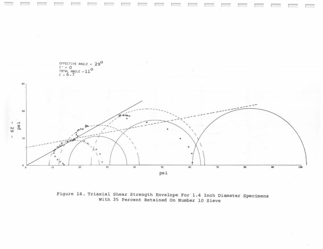
Ef f ECT/VE ANCLE • 29° C' • 0 0 TOTRL ANGLE . 11 C • 6.7
-- ---'::I'""-e , --.!",
'I·
, , - -,<,.-
, . , , Bo- -, ..
~ , ' -/------'-'/,
, '" / "
'" \ . • .. ..
-~- ..
, ,
-- -
\
..
,
,
.. psi
,
•
..
------------- -
.. ..
Figure 14. Triaxial Shear Strength Envelope For 1.4 Inch Diameter Specimens With 35 Percent Retained On Number 10 Sieve
r-- r- r-
.. .M

IN o
11 --~:!. " "ioJ .!!. .. _m
n ~.!. .. -0
•
•
0' ....... U I'd
•• • • '''J' ..
• c~_ •••• • "z ..
•
• : •
.. • • ,.
.' •
" '0 ·
•
.':~
.. -· "'----,.-..-. 1,0110
Figure 15 .
"' .... 0 .. 21 pel
-~. "-• roo II '" ... • ,,:I.
•
. , . -,. • •
..
•
•
... "'-
'. '. ", · ,'---.-,,-;; o 'ox.
,,'""0 .. lO pOll
....... ' ..
· , ' ......... . I If X ..
•
• -• •
..
0" .. .....
• •
,'. .....
· ''---,.-,-;; • - •• X H
III' ...... 45 ,.1 • •
. ..... . · c· .... · '. "1 .. .. ." • -• •
..
• •
. •
• I •• _.
' .. ' .
.. • ..
Stress With
Strain 40 Percent
Relationships Retained On
of 1.4 Number
Inch 10
Diameter Sieve
dJ ...... ' 0 ~1 . .
I" .. 10 __
•
." • 'L_~:;-,-,O . - .0 Z 10
•
• -• •
0'· .. '. ,_
0' • '. "-
"L 0 0 ,0 f"IO
Specimens

~
w ....
." It
r-""
~
~
r- ,.......
EFfECTIYE RNGLE • C· ·0 0 TOUIL ANGLE. 5 C ·15.2
r-"""" ,.......
34°
_ _ .rd:-..;-r--=---
r- r- r-
--------- ...... -----S ---=-=-=-- -
•
r-"""" r- r-"" r-"" r- r--
---~ --~<:"-~
~
-------- ---• .,.,..;;..""" _ ......... , .... :fl,
. " • , ,
"
• ~ • "
• •
, , , • I .11 • f" , , , , ,
II ,
H " ..
, , , , \
• /\ •
~. PS,l.
..
, \
'. \
\
" ..
Figure 16. Triaxial Shear Strength Envelope For 1 . 4 Inch Diameter Specimens With 40 Percent Retained On Number 10 Sieve
r-- r-- r--
.. ,.

<:11 ""'0 • n ,d
,,1 ". :!:!
" ~'¥ ...... .. • ..
~:! .. ....... , -. , "
, "
~,
w " IV
" • •
f! L " . :;~ : ....... .. _0
" , •
Figure 17.
<:11 .... 0
• U ,.1 <:11 .... 0 • 10 pol ,,1""'0. 10 pol
, , • , , ,
". .. .. . . ..
~ .
, :~ ... - '"
,
," ........
" , • "
, • " , •
, ~, ~, '"
" " • " " " • • • • • .......... , • .:PI~~ ... - •
L " :' -. " , • ,. x ,.. ,
" ,
" " , •
Strain 2.0 Stress with 20 Percent
Relationships of Retained On Number
,,1 .... 0 • 60 pol
I .. ··· ....
L "
, "
'" .' •• ;.v= :
'.'
~~: •• •
"L , "
, •
Inch Diameter 10 Sieve
"''''0 • 60 pol
,
, ...... , ': • f,··· ....
F o~ "
, • . ' ..
" I .....
X' • "
"I , , I • "
, •
Specimens
- r--"
~,
" . ~ ~
w '" w
"
00
r- r- r r- r-"" r-"" r-"" r--" r-"" r-- ,--.
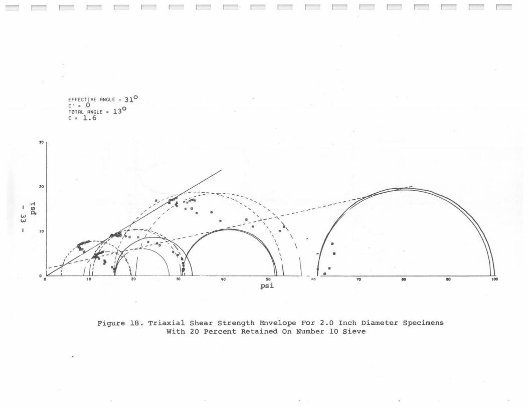
EFF[CliVE ANGLE· 31° C' • 0 lOTAL ANCLE • 13° c. 1.6
, , ",II, -
, , ,./ ,
---~ - -.Jo .;.",. --
" ' -' . . ... ... • •
•
, , , ' , '. -~ --",
----t.,_ -,- '" ... ..
. ,' .. .. .. - . :,,\,
. , , ~ . , . ~ ~ . '
-'
\
\
--
" ,,"l \
-.<4;;-;, ~_#1=:i--' i,,'o :2if,-= . " U'~~_ . - , -
' M
" psi
---
•
• • ~ ~ ..
Figure 18. Triaxial Shear Strength Envelope For 2.0 Inch Diameter Specimens With 20 Percent Retained On Number 10 Sieve
..
r- r-
,.

ctl-o - 15 PIli ,
d-o-30pai ';-110 .60 pd
• , •
-- • . -, • • ~ T ~- • <'J<'J"'''', 2.~ ~ .... ~ • • " • ,. , , • , . ~~ .a:!. ......... --- ',;"" .. "--• • .'" 0 0 0
0 " % " 0 " ,
" 0 " % " • • • ,: ." ...... w "I "[ ''I-... e'" !lee
• .. " 'l • ~ ~ ~. ~ ~ ~ .. -" J"""'- 20 Jf "" " t- .. • • - " "L " t ... '? -
.a~
•• . " 0 0 0 " % " COlO f. 20 0 "
, " -• • •
Figure 19. Stress - Strain Relationships of 2.0 Inch Diameter Specimens With 25 Percent Retained On Number 10 Sieve

I 0" m we. '"
r
~
~
"
r
EfFECTIVE ANGLE .320
C' • 0 TOTAL ANGLE • aO
c • 6 . 0
-- -- ----- ... , ,
, .. , .,;. __ J_ ...
----~/----)~ .- 1' . \
I • '-• ,
•
, ,
• -... ..>- - ---- -.-- ...
--~ \. ------ .......- . --....... \
, , •
r r ~ r- ~
----------.-
• •
. 1/ I I I Y . \ 1\:/ \ o 10 ~ 10 " 50 .., 70 10 .. ."
psi
Figure 20. Triaxial Shear Strength Envelope For 2 . 0 Inch Diameter Specimens With 25 Percent Retained On Number 10 Sieve
r-

... a-
6 1 -uO .. 15 pai 6 1 -1:10 .. ]0 l*i ~~ .. 60 ~i
, • • •
~ • l" , , ,
v"¥ .. .. ..• l"ee '21- I.aaaaa-e_
" " .,1 , , , e~ r" ( ........ J.-- .. _ • • "0 0
- ........ 0 0
0 " '- " 0 " '- " 0 " '- " , • • •
", ", ", . ' . • a.~
" t .. " " •
~ ~ ~ ~ ~ .a ...... ~
" " 0- .. " 0·-"- • • •• " " , - ~ . "l O~ " . " r~ .......
e~
• • "[:J 0 • 0
, 0
0 " '- " 0 " '- " 0 " '- " • • •
Figure 21. Stress - Strain Relationships of 2.0 Inch Diameter Specimens With 30 Percent Retained On Number 10 Sieve
.

-
w ....
r- r"""" r- r"""" r- r- r r-- r- ,.--.. r- r-
~
~
"" • "
"
--1/ • •
EFFECTIVE RNGLE .. 32° c· .. 0 TOTAL RNGLE C • 2.8
• 12°
-;.-;.-...
, __ J./ B / .
• •
"
-, -
,
... ~ .• -"," J(' ..
"'" .. - r- -~ __ = :;;:-..... , , , •
\ . \ • • •
•
----:---•
~ '0 .0
--------" ')._ ... --------- " ,
\
\ • " \ •
~ ~ " psi
Figure 22. Triaxial Shear Strength Envelope For 2.0 Inch Diameter with 30 Percent Retained On Number 10 Sieve
-Specimens
r- r- r-
- ,.
.,'-0 - 18 p-i 6'""\10 - '7 p.i til-v - 70 pd 0
• • •
~ - • • • f 1 • ~~ • "e • ." ~ __ . .£~ 0
" .1". - ... • /~
0 , , · '0 , 0 • ,~
2.~ •• 0" • . ~. .. ... • • • • . '" . ... " . , 0 , 1-0 " y. " 0 " y. 20 · , 0 00 " •••• • • .. "c •
• "" "" ", " •
• w .. I "I .. I: (XI . '"
::' 1 ..... ~r 0
~ ~ . ~
• • · .......... 20 ... 20" • " • 0
" 0
• • , -~
10 ~.e 00' 00 ,of '. ,~ " .... 2.~
• • .'" , • , • , , 00 y. " , 00 y. "
, 00 y. 20
• • •
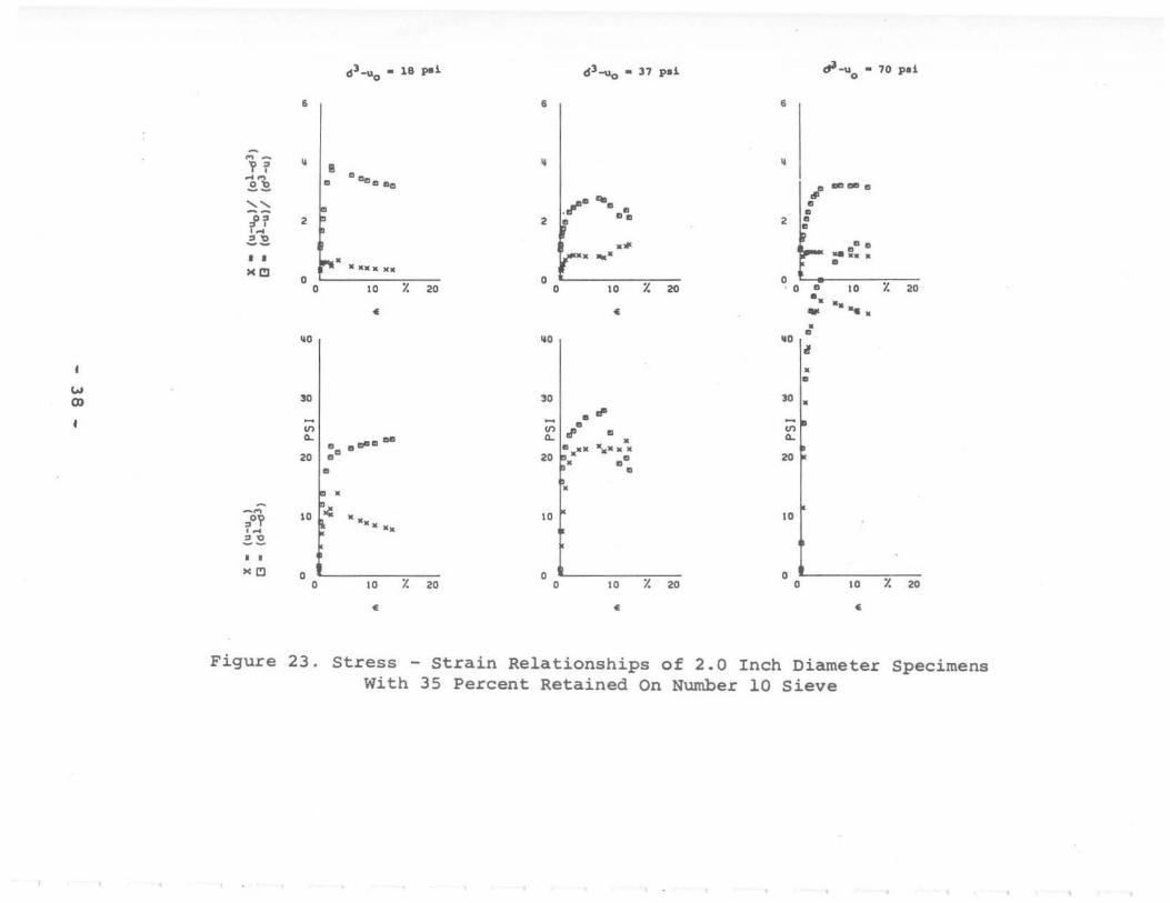
Figure 23. Stress - Strain Relationships of 2.0 Inch Diameter Specimens With 35 Percent Retained On Number 10 Sieve

." w • '" '"
•
•
"
o rff[C l lVE !'INGLE' 32 C' • 0 lOll'll ANCU • 13° c · 3 .6
, , _-r
, , • ..J.._
,
/
", . , . , , ,
---, -.~
, ,
/"
\
~. -- - ---
,
,
I
,
, , , - '-, , ,
, \
\
\
r r-" r-
----
\
,Cd:: , " • • ~ • • • • • ,. psi
Figure 24. Triaxial Shear Strength Envelope For 2.0 Inch Diameter Specimens With 35 Percent Retained On Number 10 Sieve
r- r-
cr-o - 15 pi ~'"'\Io - 30 pd
• •
~ - , - , H '. ~ '. ~~ CIt! 'fJ D 'fJ.fJ o 'fJO 0 a-~~ " " n , , ,~
.0 2.~ .. , •• • .'" • • • •• 0 0
0 " ,
" 0 • " ,
" .' ~ • • •
" • " • • ...
0 • •
" • " ~ ~ ~ • ~
" " ~.
- "1 •
.'Y • ,~ " • 2.E ,
" • . " • • • . ", •
0 0 I 0 " I,p y. " 0 "
, " . '-
• •
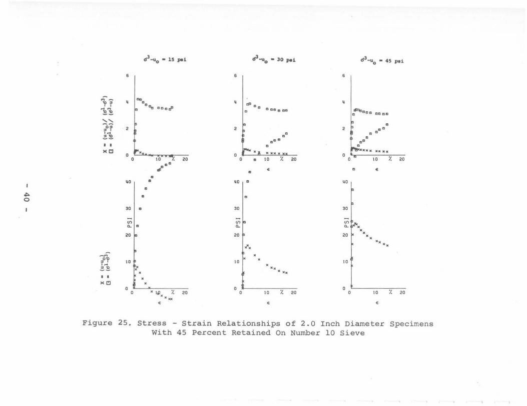
Figure 25. Stress - Strain Relationships of 2.0 With 45 Percent Retained On Number
Inch 10
0-3_ - 45 pd o
•
, ot6OttJee 'fJ DO e'fJ
• , ." • 0
• .0
• ...... " 0
0 " ,
" • •
"
.. ~
,:r···· '. '. "
0 0 "
, " •
Diameter Specimens Sieve

. ~ ... . ... 0,
•
0'-
"
,
EfFECT r~E IINCLE • 340
c· • 0 0 TOll'lL liNGLE· 9 r • 18.7
. -•
"j •
---
•• '/. ". , , ~7<
f
,
-- -e ~!!" -----
,.~y~
---. / \
• •
• •
•
------
, , , , , \
\
, , , , , , \
r
\
\
--
,--, r-"'
o 1 /" • * o ,. l(! , . •• .. Ie >0 • III ,au
psi
Figure 26. Triaxial Shear Strength Envelope For 2.0 Inch Diameter Specimens With 45 Percent Retained On Number 10 Sieve
r-'" r- r-

M _
V 1 "M
~~
" f1 Z~
• • x."
... '"
~ n '" 2.~
•• x."
Figure
6'_ .. 15 pd o
•
• IJPOooao a -• • ,
••••• , '-0 ,
" l. " •
"'
"
,: I ~i'" .-10 ... .. _
, 0
0 " l. " •
6'-\lo .. 30 pd
•
• I
,p'~ 00 0 0 0
• , • • ... ,- • •••• ,
0 " l. " •
"" ,.I .' . • • ~I . 2: , .. 0
, ,-" , , , , , , •
10 r.
0 , , ,0 l. "
•
27. Stress Strain Relationships of 2.75 With 10 Percent Retained On Number
6 3 -"0 .. 60 pel
,
•
~o"" 0 •• : , ........ ,
0 0 " l. "
• 1, ......
• "' •
" , • • , , , '0
]0 I "
~
~ I: "
"
0 0 .0 l. " •
Inch Diameter Specimens 10 Sieve

... w
.~
it
•
•
"
o EffECTIVE IIIIClE • 31 c· · 0 0 'otlll RNGLE . 18 ,. 0
'. ,
, " .. ... ,
'. •
r
~~---------
~~~
~~
I ----.L --
.'.'. /'. ~~-----.~ / __ ..... >/;::-r I ---- j' " . ~~ . /' . . ' .• \ . \
'~~.
•
~ .
• , , , , , \
\
\
r-.
,1..-?-1 'fI n f . 1 o 10 •• >II •• 50 ... ,. IICI 10 ,.
psi
Figure 28. Triaxial Shear Strength Envelope For 2.75 Inch Diameter Specimens With 10 Percent Retained On Number 10 Sieve
r- r-'"

d 3-uo • is peJ. d 3 _0
.. 30 peJ. d 3 -uo .. 60 p.J.
, , • I • •
" - • • • , • , , , , • " " ~.!. • "'e e ... • .... ••• I.,"' ''"' e aell. e " • • •
" , , •• , · , • '" Z.!. ...... " .......... ... """ ... ... f .................... • • • • 0 , , , ,
" ,
" ,
" ,
" ,
" ,
" • • • .., "I "I "I
• • .. .. .... , .., .,.,., . •• ••
0
" " ':1_ ~ 00 ~ ~ ~ ~
• " " •• :e:11 20 I • .....
• '. -" I .... "r ,'? 10 ,lAme lie •• : Ie " '" 2.2 • • . '" • , , • , ,
" ,
" ,
" ,
" ,
" ,
" • • •
Figure 29. Stress - Strain Relationships of 2.75 Inch Diameter Specimens With 20 Percent Retained On Number 10 Sieve

r I
"
" ,
. .< ~ 0.
"' .. I '"
, 0
0
r
fFFECllVE RNGLE • 30° c· .. 0 HITRL RNGLE C .. 0.6
,
_ 140
;.r:::---------/. --' -, -~", "
. '
. ---' ' 7- ----~-. .', --- --.. , . ----~- '
-- • \
" " .. ~
psi
r r-"
-----
'. \ •
•• " ~ ..
Figure 30. Triaxial Shear Strength Envelope For 2.75 Inch Diameter Specimens with 20 Percent Retained On Number 10 Sieve
r- r-"'
,.

d1"'\lo • 15 ~i d 1 -., _ 10 pi dl"'"'\,\O - 60 p.i
• • •
" -V? , • • ~" ~~ ( .... _. " ,p ...... ....... 1 .-- .. -.. '"f1 :~ .. -.. '" ,~
, , , Z~
• • ...... ".,," ." .. " .. " "i!I
• • , • • " r. " • " r. 20 • " r. " • • • .. .. .. ... . " .. " " " ... " _ D· ••. '" .--•
" " " I ~ ~ ~ ~ ~ ~
•
" 20 " ...... " II 20 . -. ~ •• D --1\> 10 1$11 •• n~~:: " I " ,~
z~
• • "'" • • I • • " r. " • " r. " • " r. 20
• • •
Figure 3l. Stress - Strain Relationships of 2.75 Inch Diameter Specimens With 25 Percent Retained On Number 10 Sieve
-
.. ...
r- r r r r- r-"' r-" r-" r- r-"'
• .<
• '"
K
~
I
"
EFFECT lYE ANGLE ... 31° C' .. 0 TOTAL RNGLE ... 13° c ... 0.5
------,
I . / .......
c-, . , . , ,
. , ,
-------
•
---, ---, , --,-, -' , -<: , \
• \
'/ ~:' \ •
. ~:-(;.;! '\' \ ! j 1 a LO ~ " .. " .. " .. ..
psJ
Figure 32. Triaxial Shear Str~ngth Envelope For 2.75 Inch Diameter Specimens with 25 Percent Retained On Number 10 Sieve
r- r-"
, .

•
d l __ 15 pd o
•
dl-vo - lO pd dl-u.o • 60 I'd
•
".< • .. 0.
'"
"
M
"
,
EFFECTl .... E RNGLE .. 32° c· a 0 0 TOTAL RNGLE . 12 c .. 1. 7
• /
.-+---/
i , '>-- ------; ....
•
, , -. --,
~ \ •
. -- - --
• •
-----•
, , .... --_ -'C"
.------::-..... \
\
I
--
•
ole" "\\ T \\
r r r r r- r- r-
,
----- ------- -
• •
o 10 20 '0 .0 10 .., 10 to to I • •
psi
Figure 34. Triaxial Shear Strength Envelope For 2.75 Inch Diameter Specimens with 30 Percent ~etained On Number 10 Sieve

(11""'\,\0 - 15 pd ,r""'\,\ - 10 pd o d1-uo - 60 ~L
, , •
11 •
r·~·· -. •
l,···· "'-' •
"11. I_ dI - - -- - -
" • • 1] , , , • z.:c , , r···· . '" ... o t···· ...... -..... • • • Ol
0 o 0 LO;: 20 o 10;: 20 0 II ~.-- "
• • • of' •
"I "I • ~O I ..
'" •• 0 • • •• • •
• ,. " ,. .. ' Vila ~ ~ .' .
~ ~ .0' ~
• " " I·· .. " --~ -- • • ••• .. ' ••
Jj " F· "I " '" Z~ · ..... , , ." 0
, o i>- 0 0 " % " 0 " % " 0 " % "
• • • Figure 35. Stress - Strain Relationships of 2.75 Inch Diameter Specimens
With 35 Percent Retained On Number 10 Sieve

V> ....
•
• 0.<
Ii
"
[HEeTI¥[ AJ(Cll • 32° c· ·0 0 tOlAt ANelE . 18 c • 1.2
, • ..!_ ,J
" -
, , ,
I
.. I ........... ~ '"i''':::' ~'' ---r '~'- "
I ... ....
"'- - , y \
L r r r- r-
------. -..- , , ,
,
..,,-~ - .\ 7' · V-I I i l k' \
o ,0 III 10 •• 10
Figure 36. Triaxial Shear Strength Envelope For 2.75 Inch Diameter Specimens with 35 Percent Retained On Number 10 Sieve
r-

6]-110 .. 15 I'd , d ""'Uo .. 30 p.1 crl-uo .. 60 1'.1
• • , • I
" - •
r'~" .... : • ~.~.
• H • 11- ........ .. .... .......... " • • '0'; • , , , • , , • ,~
Z~
• • ,.. ••• x· t'" • ••• C·· X
! • OJ .' . 0
• • •••• 0 o '--
0 " ,
" 0 " ,
" 0.. 10 7. " • • • •
" " ''I" U>
'" ••••
" . " 0
", ", 000 " I. 00 ",0
,: I ~ 0 :c I. ~ .......... 0
" " ,pO ". • ••• • • 0 0 •
~ on "f " " ,~
'" .. " -- • ••••• • • 'OJ • • 0 0 0
0 " ,
" 0 " ,
" 0 " ,
" • • •
Figure 37. Stress - strain Relationships of 2.75 Inch Diameter Specimens with 40 Percent Retained On Number 10 Sieve

r
.~
• '" 0. w
r ,---. r- r- r-" r-
EffECTIVE A~CLE • 32° C· • 0 ISO H"IIL AN~l[ • , . 2.0
-~............... - ~ " .~,' .::.- .....
/" - , .-,. , . - , y" ., , , , ,
/,: ' -<-~ \ , --\
.---7-·. : .... --- • \
" ~'. '" . "
" I
f , "
, -;/ ( V:
.v • "
, • .. .. .. , • • , . psi
Figure 38. Triaxial Shear Strength Envelope For 2.75 Inch Diameter Specimens with 40 Percent Retained On Number 10 Sieve
r-" r-"
~ -~ 1 . ~ ~E.
" 11 ' . .=.~
• • "~
'" ..,
-n '-n --• • ""
Figure
0 1 _" .. U p_i o
,
• ~.~~ : ............ ,
of:..."" .. ! •••• o 10 j(
•
"I
,,' .0
000
",'
~I . 2: 8'
0
"
"L 00 10 ·°j( 20
•
(f1 _Ug .. 10 pd
,
• r' o
""
0
,
t:: ...... • , , " y. " •
"I o 00 0
00 0 • 0
0
0
" • ~
~
" •
" • • · '.
, f , "
y. " •
39. Stress - Strain Relationships of 2.75 with 50 Percent Retained On Number
d1-"o .. 60 pd
,
• 0 ~ ..........
0 0
0 , E 0
t· ..... .... , 12 ........ , 0 ;;;0
" y. " 0 •
" 1
0
" III L .00. •• • ~ . •
" I· "
.i , " y. " •
Inch Diameter Specimens 10 Sieve

M
.. , ...
e on", on
"
• V •
, ,
EffECl lYE PMGl[ • 34° c· ·0 TOTAl ANCLE • 17° c ·6.9
, , r
., ' , , , ,
, ---- . u' • ----. .--! -~-- -~.- :.. -.-~
/
, / ,
---, , ,
•
r
. ------- -
------.... - , , ,
--, , , , , , , , ,
r- r-
\
\
\
--- / . ., f \
/ • •
"
, "' / ,
~ .
J .. M • y • ~ • • psi
Figure 40 . Triaxial Shear Strength Envelope For 2.75 Inch Diameter Specimens With 50 Percent Retained On Number 10 Sieve
r- r-
,.
