nvx suspended gas unit heater range - powrmatic · nvx suspended gas unit heater range ......
TRANSCRIPT

NVx Suspended Gas Unit Heater RangeIndustrial & Commercial Heating Systems.
w w w . p o w r m a t i c . c o . u k
H E A T I N G / / V E N T I L A T I O N / / A I R C O N D I T I O N I N G / / O E M P R O D U C T S

2
Models Available
• NVx F - Axial Fan Crossflow Units
• NVx Duo - Axial Fan Bi-Directional Units
• NVx V - Axial Fan Downflow Units
• NVx C - Centrifugal Close Coupled Fan Units
• NVx D - Ducted Heat Module (no fan)
Installer Friendly
• New compact model• Downflow & bi-directional models available• Horizontal wall exit flue discharge option (no roof work)• Fan assisted flue that can be room sealed• Interchangeable top or rear flue/combustion air spigot positions• Centrifugal fan option
Peace Of Mind
• More Than Sixty Years Experience in Warm Air• 2 Year Parts And One Year Labour Guarantee• 10 Year Sliding Scale Time Related Heat Exchanger Warranty
Application and ConfigurationThe NVx range of gas fired unit heaters comprises 13 models with outputs ranging from 15 kW to 140 kW. The heaters are typically installed directly into the space to be heated with ducted applications satisfied using the centrifugal fan option. Suitable for either natural or LPG gases, heaters can be specified/arranged for on/off, high/low or modulated heat outputs.
EfficienciesFavourable levels of fuel usage and reduced emissions are a key element of NVx heater design. Additionally, all heaters have efficiencies which meet or exceed the requirements of current Building Regulations. Efficiencies can be further enhanced with the selection of the modulating burner option.
CabinetThe heater unit is of unitary construction and provided with a separate compartment with a full width hinged and lift-off door giving easy access to heater function controls, gas valve and burner. The cabinet is finished with durable epoxy powder coat stove baked paint.
Heat ExchangerFour pass tubular assembly manufactured from aluminised steel formed, swaged and expanded without recourse to stress inducing welding. 409 and 316 grade stainless steel options available.
Approvals All Powrmatic heaters are type tested to meet the stringent requirements the Gas Directive and are CE approved.
Burners Multi in-shot burners matched to each tube assembly and manifolded to a common gas valve and ignition system, itself complete with flame monitoring and safety controls and supplied ready for use with natural gas (G20). Alternative LPG propane (G31) firing available to order.
Air MovementAxial fan heaters are, dependent upon model, fitted with either single of multiple fan sets and discharge warmed air directly into the heated space via adjustable louvred horizontal grilles.Centrifugal fan models are fitted with the centrifugal fan mounted directly to the heater and discharge via a duct outlet spigot mounted to the front of the heater.
Controls As standard, Powrmatic heaters are supplied with high temperature limit protection as well as connections for heat and, where applicable, fan-only operation. For enhanced control the heaters may be connected to one of our compatible environmental control stations. These are available in three options: •MC200V3 (control of single units)Tamper-proof digital control featuring optimised start/stop, digital time switch, electronic and frost protection thermostats. Remote temperature sensor option available.
•MC300 Multi (control of multiple units)The MC300 multi is functionally identical to the MC200V3 with the added ability to control up to five heaters from a master MC300 control. For ease of installation and to reduce installation time and cost slave pcbs are factory fitted with connections between master and slave enabled with low voltage control cable.
•Powrtrol (control of single units)As an alternative to the MC control units, Powrtrol control stations provide a digital time switch with mechanical day and frost protection thermostats and a switched fan-only option for summer operation. Heaters controlled using Powrtrol do not qualify for Enhanced Capital Allowances.
Note: Interconnecting wiring for all controls is the responsibility of the installer. Visit www.powrmatic.co.uk for more information.
NVx Overview

3
Model 15 20 25 30 40 50 60 75 90S 90 120 140
Output kW 15 20 25 30 40 50 60 75 90 90 120 140
Input (nett CV) kW 16.00 21.85 27.32 32.60 43.48 54.23 65.60 81.30 97.80 95.30 130.1 148.9
AirflowVolume
NVx F / C / V m3/s 0.39 0.52 0.65 0.78 1.00 1.30 1.56 1.95 2.34 2.34 3.12 3.64
Duo m3/s N/A N/A N/A N/A N/A N/A N/A N/A N/A 2.34 3.12 3.64
NVx DMin m3/s 0.31 0.42 0.52 0.63 0.83 1.04 1.25 1.56 N/A 1.88 2.50 2.92
Max m3/s 0.42 0.56 0.69 0.83 1.11 1.39 1.67 2.08 N/A 2.50 3.33 3.89
AirflowThrow
NVx F m 10.0 13.0 16.0 15.0 21.0 24.0 25.0 29.0 38.0 31.0 35.0 37.0
NVx Duo m N/A N/A N/A N/A N/A N/A N/A N/A N/A 48.0 50.0 58.0
Fan Static
NVx C Pa 145 177 143 250 236 205 250 260 N/A 200 284 285
Electrics
SupplyStandard V/ph/Hz 230/1/50
Optional V/ph/Hz 400/3/50 (Centrifugal Unit Only)
NVx F
Motor kW 0.12 0.13 0.18 0.18 0.27 0.39 0.66 0.66 0.902 x
0.392 x
0.662 x
0.66
Start amp 0.08 1.05 1.54 1.54 2.40 3.76 5.90 5.90 6.48 5.0 7.8 7.8
Run amp 0.54 0.33 0.07 0.07 1.20 1.70 2.80 2.80 3.60 2.30 3.8 3.8
NVx C
Motor kW 0.25 0.37 0.37 1.10 1.10 1.10 1.40 1.40 N/A2 x
1.102 x
1.402 x
1.40
Start amp 4.50 12.60 12.60 18.50 18.50 18.50 28.90 28.90 N/A 31.00 40.00 40.00
Run amp 1.50 4.20 4.20 6.40 6.40 6.40 12.50 12.50 N/A 12.80 25.00 25.00
Fuel
Connection BSP/Rc ¾”
Minimum Inlet Pressure
Nat Gas
mbar 17.5
LPG mbar 37.0
ConsumptionNat Gas
m3/h 1.69 2.31 2.89 3.45 4.60 5.73 6.93 8.59 10.35 10.07 13.77 15.74
LPG m3/h 0.65 0.89 1.12 1.33 1.78 2.22 2.67 3.32 4.00 3.90 5.17 6.09
Mounting Height
NVx F/DuoCrossflow
Min m 2.5 3.00
Max m 3.0 5.00
NVx V Downflow
Min m 4.00 4.00 5.00 N/A 6.00 6.00
Max m 6.00 7.00 8.00 N/A 10.00 12.00
OverallDims
NVx F
Height mm 540 540 540 760 760 912 760 912 975 700 831 975
Width mm 1000 1000 1000 1000 1000 1000 1325 1325 1575 2325 2325 2325
Depth mm 892 925 925 925 905 925 939 985 915 925 939 939
InstallClearance
NVx F
Top mm 200
LH Side mm 200
RH Side mm 1000
Rear mm 400
Flue
Diameter mm Ø 80 80 80 100 100 100 130 130 130 130 130 130
Max Length
Flue Only m 12
Room Sealed m 6
Combustion Air Spigot mm Ø 80 80 80 100 100 100 130 130 130 130 130 130
Noise Levels NVx F dB(A) 54 52 53 54 58 61 62 62 76 66 67 67
Nett WeightNVx F kg 69.5 69.5 74.5 96 108 123 138.5 158 203 204 260 280
NVx C kg 106.5 120.5 126.5 166.5 168.5 183 213 234 N/A 343 363.5 424
Duties
Notes:
Fuel Consumption and input figures based upon nett calorific values as follows: - Natural Gas (G20) nett CV 34.02 MJ/m3
- Propane (G31) nett CV 88.00 MJ/m3
• Heaters have efficiency levels which meet with the minimum heater efficiency requirements of UK Part L Building Regulations• Air handling data is assessed at room ambient conditions• Throw figures provide the distance to the point where the terminal velocity degrades to 0.25m/s• Dimensions and clearance data in the table above refer to NVx F units only - for NVx C and NVx D data refer to the dimensions page and/or the installation instructions• Noise levels are applicable to standard NVx F models and are measured 5m from appliance in a typical installation situation.• Motor kW, run and start amps apply to standard electrical supply as stated. For optional data contact sales office• Connection of combustion air duct is not required for ‘flue only’ applications• The NVx Duo throw dimension is the effective combined throw measurement• It is the responsibility of the installing contractor to ensure that ductwork is correctly sized and balanced when installing NVx Centrifugal units• Installer guidance notes on rear page

R/H SIDE VIEW
A
REAR VIEW
NVx F 10-90SPLAN
FRONT VIEW
N
PF
G
E
G
M
HJ CTRSK
122
228
228
122
CTR
SC
TRS
B
ØD
35
L
C
NVxF 90-140PLAN
E
G
M
122
228
228
122
CTR
SC
TRS
Q
SUSPENSION POINTS M10
GAS ENTRY POINTELEC ENTRY
K J CTRS J CTRS H
4
DimensionsNVx F - Axial Fan Crossflow Units
Model 15 20 25 30 40 50 60 75 90S 90 120 140
A mm 1000 1000 1000 1000 1000 1000 1325 1325 1575 2325 2325 2325
B mm 700 700 700 700 700 700 700 700 700 700 700 700
C mm 540 540 540 760 760 912 760 912 975 700 831 975
DØ mm 80 80 80 100 100 100 130 130 130 130 130 130
E mm 248 248 248 233.5 233.5 233.5 235.5 235.5 235.5 235.5 235.5 235.5
F mm 308 308 308 492 492 644 416 568 631 356 487 631
G mm 120 120 120 142 142 142 220 220 220 220 220 220
H mm 317 317 317 317 317 317 347 347 347 347 347 347
J mm 250 450 450 450 450 450 700 700 950 2x850 2x850 2x850
K mm 218 232.5 232.5 232.5 232.5 232.5 278 278 278 278 278 278
L mm 892 925 925 925 905 925 939 985 915 925 939 939
M mm 216 216 216 206 206 206 236 236 246 246 246 246
N mm 114 114 114 114 114 114 145 145 88 88 88 88
P mm 194 194 225.5 297 297 374 297 374 398 243 326 398
Q mm 157 190 190 190 170 190 204 250 180 190 204 204
NVx 120 FNVx 75 F

L
A
REAR VIEW
PLAN
FRONT VIEW
N
PF
GE
G
M
122
228
228
122
CTR
SC
TRS
R/H SIDE VIEW
B
C
Q
GAS ENTRY POINTELEC ENTRY
SUSPENSION POINTS M10
K J CTRS J CTRS H
5
DimensionsNVx Duo - Axial Fan Bi-Directional Units
Model 90 120 140
A mm 2325 2325 2325
B mm 700 700 700
C mm 700 831 975
DØ mm 130 130 130
E mm 235.5 235.5 235.5
F mm 356 487 631
G mm 220 220 220
H mm 347 347 347
J mm 2x850 2x850 2x850
K mm 278 278 278
L mm 1120 1182 1182
M mm 246 246 246
N mm 88 88 88
P mm 260 326 398
Q mm 190 204 204
NVx 120 Duo

R/H SIDE VIEW
C
PLAN FOR NVxV 10-75
N
PF
G
E
G
1325
LB+70mm
FRONT
C+30mm
J CTRS J CTRS
M
A
REAR
ØD
PLAN FOR NVxV 90-140
N
P
G
J CTRS J CTRS J CTRS J CTRS
C+30mm
K H
F
K H
DROP RODSUSPENSION POINTS M10
ELEC ENTRY
GAS ENTRY POINT
6
NVx C - Centrifugal Close Coupled Fan UnitsDimensionsNVx V - Axial Fan Downflow Units
Model 15 20 25 30 40 50 60 75 90 120 140
A mm 1000 1000 1000 1000 1000 1000 1325 1325 2325 2325 2325
B mm 700 700 700 700 700 700 700 700 700 700 700
C mm 540 540 540 760 760 912 760 912 700 831 975
DØ mm 80 80 80 100 100 100 130 130 130 130 130
E mm 248 248 248 233.5 233.5 233.5 235.5 235.5 235.5 235.5 235.5
F mm 308 308 308 492 492 644 416 568 356 487 631
G mm 120 120 120 142 142 142 220 220 220 220 220
H mm 283 283 304 283 283 283 312 312 299 350 312
J mm 260 260 260 260 260 260 385 385 442.5 442.5 442.5
K mm 197 197 176 197 197 197 243 243 256 205 243
L mm 892 925 925 925 905 925 939 985 925 939 939
M mm 216 216 216 206 206 206 236 236 246 246 246
N mm 114 114 114 114 114 114 145 145 88 88 88
P mm 194 194 225.5 297 297 374 297 374 243 326 398
NVx 60 V NVx 60 V

R/H SIDE VIEWA
REAR VIEW
PLAN FOR NVx C 10-75
FRONT VIEW
GAS ENTRY POINTN
PF
G
E
G
M
J CTRS
C
ø D
35
NOTE: For dimensioning purposes both top and rear flue and combustion air connections are shown
LB
K H
T
S
ELEC ENTRY
E
M
K J CTRS J CTRS H
G
228 CTRS
228 CTRS
122
122
228 CTRS
228 CTRS
122
122
PLAN FOR NVx C 90-140
SUSPENSION POINTS M10
7
NVx C - Centrifugal Close Coupled Fan Units
Model 15 20 25 30 40 50 60 75 90 120 140
A mm 785 1000 1000 1000 1000 1000 1325 1325 2325 2325 2325
B mm 700 700 700 700 700 700 700 700 700 700 700
C mm 540 540 540 760 760 912 760 912 700 831 975
DØ mm 80 80 80 100 100 100 130 130 130 130 130
E mm 248 248 248 233.5 233.5 233.5 235.5 235.5 235.5 235.5 235.5
F mm 308 308 308 492 492 644 416 568 356 487 631
G mm 120 120 120 142 142 142 220 220 220 220 220
H mm 317 317 317 317 317 317 347 347 347 347 347
J mm 250 450 450 450 450 450 700 700 2x850 2x850 2x850
K mm 218 232.5 232.5 232.5 232.5 232.5 278 278 278 278 278
L mm 1317 1356 1356 1430 1430 1430 1505 1505 1430 1505 1505
M mm 216 216 216 206 206 206 236 236 246 246 246
N mm 114 114 114 114 114 114 145 145 88 88 88
P mm 194 194 225.5 297 297 374 297 374 243 326 398
S mm 637 637 637 637 637 637 932 932 1932 1932 1932
T mm 492 492 492 712 712 864 712 864 617 783 927
NVx D - Ducted Heat Module (No Fan)
Dimensions
NVx 50 C (Front) NVx 50 C (Rear)

8
NVx D - Ducted Heat Module (No Fan)
Model 15 20 25 30 40 50 60 75 90 120 140
A mm 785 1000 1000 1000 1000 1000 1325 1325 2325 2325 2325
B mm 700 700 700 700 700 700 700 700 700 700 700
C mm 540 540 540 760 760 912 760 912 700 831 975
DØ mm 80 80 80 100 100 100 130 130 130 130 130
E mm 248 248 248 233.5 233.5 233.5 235.5 235.5 235.5 235.5 235.5
F mm 308 308 308 492 492 644 416 568 356 487 631
G mm 120 120 120 142 142 142 220 220 220 220 220
H mm 317 317 317 317 317 317 347 347 347 347 347
J mm 250 450 450 450 450 450 700 700 2x850 2x850 2x850
K mm 218 232.5 232.5 232.5 232.5 232.5 278 278 278 278 278
L mm 835 835 835 835 835 835 835 835 835 835 835
M mm 216 216 216 206 206 206 236 236 246 246 246
N mm 114 114 114 114 114 114 145 145 88 88 88
P mm 194 194 225.5 297 297 374 297 374 243 326 398
Q mm 133 133 133 147 147 147 147 147 147 147 147
S mm 637 637 637 637 637 637 932 932 1932 1932 1932
T mm 492 492 492 712 712 864 712 864 617 783 927
Dimensions
NOTE: For dimensioning purposes both top and rear flue and combustion air connections are shown
33.733.7
T
S
R/H SIDE VIEW
AS
REAR VIEW
PLAN FOR NVx D 10-75
FRONT VIEW
N
PF
G
E
G
M
HJ CTRSK
B
228 CTRS
228 CTRS
122
122
C T
ø D
GAS ENTRY POINT
ELEC ENTRY
L
PLAN FOR NVx D 90-140
M
K J CTRS J CTRS H
228 CTRS
228 CTRS
122
122
SUSPENSION POINTS M10
E
G
NVx 50 D (Front) NVx 50 D (Rear)
9
B
CC
D
A
E
E
A
D
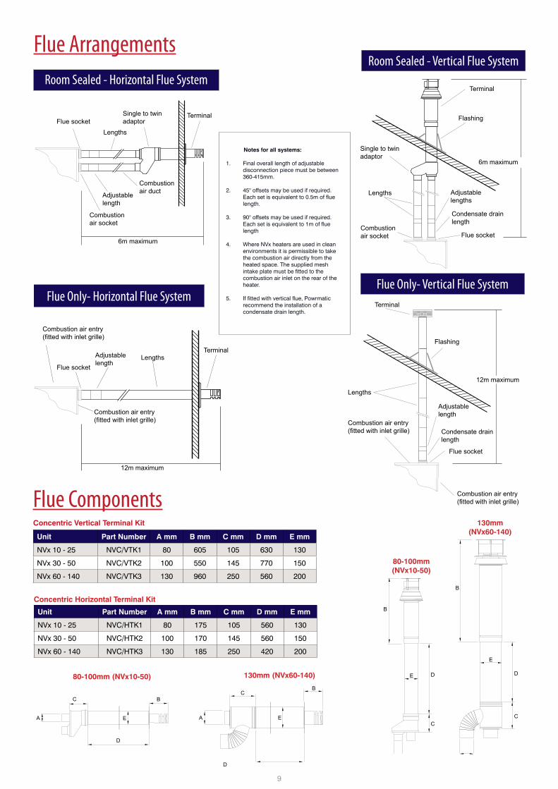
BUnit Part Number A mm B mm C mm D mm E mm
NVx 10 - 25 NVC/HTK1 80 175 105 560 130
NVx 30 - 50 NVC/HTK2 100 170 145 560 150
NVx 60 - 140 NVC/HTK3 130 185 250 420 200
Flue Arrangements
Flue socketLengths
Single to twinadaptor
Terminal
Combustionair duct
Combustionair socket
6m maximum
Adjustablelength
Terminal
Flashing
12m maximum
Lengths
Combustion air entry(fitted with inlet grille)
Adjustablelength
Condensate drainlength
Flue socket
Combustion air entry(fitted with inlet grille)
Flue socket
Condensate drainlength
Adjustablelengths
Combustionair socket
Lengths
Single to twinadaptor
6m maximum
Flashing
Terminal
Combustion air entry(fitted with inlet grille)
Adjustablelength
LengthsTerminal
12m maximum
Flue socket
Combustion air entry(fitted with inlet grille)
Notes for all systems:
1. Final overall length of adjustable disconnection piece must be between 360-415mm.
2. 45° offsets may be used if required. Each set is equivalent to 0.5m of flue length.
3. 90° offsets may be used if required. Each set is equivalent to 1m of flue length
4. Where NVx heaters are used in clean environments it is permissible to take the combustion air directly from the heated space. The supplied mesh intake plate must be fitted to the combustion air inlet on the rear of the heater.
5. If fitted with vertical flue, Powrmatic recommend the installation of a condensate drain length.
Unit Part Number A mm B mm C mm D mm E mm
NVx 10 - 25 NVC/VTK1 80 605 105 630 130
NVx 30 - 50 NVC/VTK2 100 550 145 770 150
NVx 60 - 140 NVC/VTK3 130 960 250 560 200
Concentric Vertical Terminal Kit
Concentric Horizontal Terminal Kit
Flue Only- Horizontal Flue System
Room Sealed - Vertical Flue System
Flue Components
Room Sealed - Horizontal Flue System
80-100mm(NVx10-50)
130mm(NVx60-140)
80-100mm (NVx10-50) 130mm (NVx60-140)
Flue Only- Vertical Flue System
C
A
C B
D
B
D
EA E

10
30° Downflow Head (NVx F Models Only)
90° Downflow Head - (NVx C Models Only)
Mixing Box - (NVx C Models Only)
Filter Box - (NVx C Models Only)
Model A B C D E
NVx 10 496 449 425 350 352
NVx 15-20-25 496 449 639 350 494
NVx 30-40 716 559 639 560 494
NVx 50 868 635 639 630 494
NVx 60 716 559 934 500 659
NVx 75 868 635 934 630 659
NVx 90 656 528 1934 420 659
NVx 120 787 595 1934 560 659
NVx 140 931 667 1934 700 659
Accessories
B
E
ECD
F
FA
A CD
E B
Model A B C D E
NVx 10 496 601 425 350 352
NVx 15-20-25 496 601 639 350 494
NVx 30-40 716 862 639 560 494
NVx 50 868 1015 639 630 494
NVx 60 716 862 934 500 659
NVx 75 868 1015 934 630 659
NVx 90 656 802 1934 420 659
NVx 120 787 932 1934 560 659
NVx 140 931 1076 1934 700 659
Model A B C D E F
NVx 10 865 745 502 432 520 590
NVx 15-20-25 865 745 698 628 520 590
NVx 30-40 1093 973 698 628 748 818
NVx 50 1247 1125 698 628 900 970
NVx 60 1093 973 1011 941 748 818
NVx 75 1247 1125 1011 941 900 970
NVx 90 980 860 2014 1944 635 705
NVx 120 1145 1025 2014 1944 800 870
NVx 140 1310 1190 2014 1944 965 1035
Model A B C D E
NVx 10 502 590 120 432 522
NVx 15-20-25 698 590 120 628 522
NVx 30-40 698 818 120 628 750
NVx 50 698 970 120 628 902
NVx 60 1010 818 120 940 750
NVx 75 1010 970 120 940 902
NVx 90 2014 705 120 1944 637
NVx 120 2014 870 120 1944 802
NVx 140 2014 1035 120 1944 967
BC
A
E
D
B
D
A
C
E

11
Fan Plenum Box - (NVx C Models Only)
Powrtrol/RRMC200V3 RBR Relay Boxes
ControlsA choice of control options are available for the NVx range. 5 heaters can now be controlled using the new MC300 Multi from a single master control. Visit our website to find out more about our controls systems.
RBR2 shown - control up to 2 units.Other RBR relay boxes available to
control up to 4 to 6 units.
Vertical Louvres (For Use On All Models)A
BC
Model A B C
NVx 10 395 418 66
NVx 15-20-25 537 418 66
NVx 30-40 537 628 66
NVx 50 537 698 66
NVx 60 702 568 66
NVx 75 702 698 66
NVx 90 702 493 66
NVx 120 702 628 66
NVx 140 702 758 66
Model A B C D E
NVx 10 643 510 575 494 429
NVx 15 643 725 575 494 644
NVx 20-25 750 725 575 494 644
NVx 30-40 750 725 795 714 644
NVx 50 750 725 947 866 644
NVx 60 750 1020 795 714 939
NVx 75 825 1020 947 866 939
NVx 90 825 2021 735 654 1940
NVx 120 825 2021 866 785 1940
NVx 140 825 2021 1010 929 1940
MC300 Multi
Single Unit Controls Multiple connectivity of up to 5 heaters from a master MC300 unit with each heater
factory fiited with a MC300 slave.
Single Unit Controls
Swivel Wall Bracket - ( NVx F Models Only)
Heater
474
Cantilever Wall Bracket - (NVx F Models Only)
Heater
100
500
500
105
A B
CD
E
Notes: - Dimensions for the swivel and cantilever brackets remain the same for all NVx models - Swivel Brackets can not be used with double units

GeneralThe following notes are provided as a guide, however installers and operators should fully acquaint themselves with the more detailed guidance provided in the relevant installation manual. For copies of such manuals please consult our technical department or visit our website - www.powrmatic.co.uk
StandardsAll Powrmatic NVx heaters must be installed, commissioned and operated with due regard to appropriate regulations including but not limited to BS 6230, relevant Codes of Practice, the possible requirements of Local Authorities, Fire Officers and insurers as well as Powrmatic’s installation manual.
Position & LocationPowrmatic NVx heaters can be ‘drop rod’ suspended via purpose designed M10 suspension fixing points, attached to our optional wall support brackets or positioned on a level non-combustible base. In all cases it is important that all supporting structures have due regard to the relevant weight loadings.
Consideration should also be given to flue routes and points of exit, gas, electrical and control connections, the throw characteristics of the heater, issues of public access and the siting of environmental control stations and/or remote temperature sensors where the position needs to be representative of the zone temperature to which they refer.
Heaters should not be installed in hazardous areas or areas where there is a foreseeable risk of flammable or corrosion inducing particles, gases or vapours being drawn into the combustion air or main fan circuits.
Areas where special consideration or advice may be required could include but is not limited to -
• Where de-greasing solvents are present, even in minute concentrations • Where paint spraying is carried out • Where styrenes or other laminating products are used • Where airborne silicone is present • Where petrol engined vehicles are stored or maintained • Where dust is present (i.e. wood working or joinery shops) • Where high levels of extract persist
Installation in such areas may be possible under specific conditions. Please consult our technical department for further information.
Plant Room or Enclosure Locations It is recommended that you consult with our technical department.
Combustion Air & General Ventilation Within the United Kingdom mandatory regulations apply concerning the provision of combustion air and general heater ventilation. Where a heater is installed in room sealed mode (i.e. where both the flue exit and combustion air are positively connected to atmosphere) then there is no specific requirement for combustion air ventilation. However, depending upon location, provision for general ventilation may still be a necessity.
If the heater is installed in flue only mode and directly within the heated space and where that heated space has a natural ventilation rate greater than 0.5 air changes per hour then combustion air and general heater ventilation is probably not required. If the heated space has a natural ventilation rate of less than 0.5 air changes per hour then either natural ventilator openings or mechanical ventilation will be required. Please consult the installation manual for further details.
Installation ClearancesParticular clearances may be necessary for the correct and safe function of the heater as well as for maintenance purposes. Such clearances are confirmed in the relevant installation manual.
Flue Powrmatic NVx heaters can be installed in either room sealed or flue only mode. Each heater requires a separate flue and/or combustion air intake system of the appropriate size and type. Installers are reminded that type approval has been granted for these appliances on the basis that they are fitted with Powrmatic NVx flue systems. Maximum lengths apply and should be strictly observed.
Systems may be installed in either the horizontal or vertical plane. In either case the number of bends kept to a minimum and regard must be given to the reduction in permissible length with the addition of each bend. The flue must be adequately supported and terminated with the approved terminal assembly, with due regard to the point of exit and it’s proximity to any windows, doors or ventilation intakes etc.
PipeworkCare should be taken when sizing pipe work to ensure that minimum gas inlet pressures are not compromised under dynamic load conditions. Isolating valves and service unions should be provided for each heater and pipe work installed with due regard for relevant standards and Codes of Practice.
Guarantee Powrmatic NVx heaters are provided with a comprehensive guarantee covering both the heater and the heat exchanger. For United Kingdom sales the heater has the benefit of a two year parts and one year labour guarantee whilst the heat exchanger assembly has a ten year time related sliding scale warranty. All guarantees are subject to terms and conditions.
Issue 5.7 August 2015
Powrmatic pursues a policy of continuous improvement in both design and performance of its products and therefore reserves the right to change, amend or vary specifications without notice. Whilst the details contained herein are believed to be correct they do not form the basis of any contract and interested parties should contact the Company to confirm whether any material alterations have been made since publication of this brochure.
Powrmatic LimitedHort BridgeIlminsterSomersetTA19 9PS
tel: +44 (0) 1460 53535fax: +44 (0) 1460 52341e-mail: [email protected]: www.powrmatic.co.uk
Powrmatic Ireland45 Broomhill CloseTallaghtDublin 24
tel: +353 (0) 1452 1533fax: +353 (0) 1452 1764e-mail: [email protected]: www.powrmatic.ie
Y o u r I n s t a l l e r G u i d e