n.t. 2628a x066 - x067 the automatic clutch · contents page automatic clutch introduction...
TRANSCRIPT
The repair methods given by the manufacturer in this document are based on thetechnical specifications current when it was prepared.
The methods may be modified as a result of changes by the manufacturer in theproduction of the various component units and accessories from which his vehiclesare constructed".
All copyrights reserved by the Régie Nationale des Usines Renault..
Copying or translating, in part or in full, of this document or use of the service partreference numbering system is forbidden without the prior written authority of theRégie Nationale des Usines Renault S.A.
C Régie Nationale des Usines Renault S.A. 1996
N.T. 2628A
X066 - X067
THE AUTOMATIC CLUTCHis a clutch which is controlled by a computer.
Basic Manual: M.R. 305
77 11 190 785 OCTOBER 1996 Edition Anglaise
Contents
Page
AUTOMATIC CLUTCH
IntroductionRecommendationsSpecial notesLocation on the vehiclePump-hydraulic jack assembly AccumulatorGear lever sensor (728)Engaged gear sensor (726)Vehicle speed sensor (250)Bonnet switchAccelerator position informationEngine speed sensor (120)Air conditioning information (319)Door switch (180)Computer (730)Operational wiring diagramPump assembly relay (762)Starter relay (232)Buzzer (763)OperationClutch identificationComputer identificationHydraulic fluid levelDischarging the accumulatorProgramming full load and no loadpositionsProgramming the gearsProgramming neutral position forthe solenoid and the jack positionReading clutch wearReading the date of After SalesoperationsEntering the date of After SalesoperationsFault finding
20-120-220-320-420-5
20-1720-1920-2320-2520-2620-2620-2720-2720-2720-2820-3020-3220-3320-3420-3520-3820-3920-4020-41
20-4220-43
20-4520-47
20-48
20-4920-50
20
AUTOMATIC CLUTCH
Introduction 20The design of the whole vehicle, including theclutch, is continually being improved. The latesttechnological advances have allowed a computercontrolled automatic clutch to be developed.
The special feature of this clutch is that to performthe clutch - declutch operation, a clutch pedal nolonger needs to be used.
The automatic system used in the clutch controlrequires the use of the following components :
- an electro-pump and hydraulic jack assemblywhich carries out the clutch - declutch action atthe mechanism control,
- a computer to control the assembly,- various sensors, one of which is located in the
gear lever knob.- information provided by the injection compu-
ter
MAINTENANCE (to be carried out at each visit tothe workshop)
Check:• the level of the hydraulic fluid (see section
"Hydraulic fluid level").
• the correct operation of the buzzer- start the vehicle,- engage a gear,- open the driver’s door,and the buzzer should sound.
• the safety devices preventing the engine fromstarting :
- apply the handbrake,- engage a gear,- try to start the engine,the starter should not operate.
• the safety devices preventing the vehicle frommoving with the bonnet open:- apply the handbrake,- with the engine running:
• open the bonnet and hold it in positionwith the stay,
• engage 1st gear (from inside the vehicle),• accelerate, the vehicle should not move,
the buzzer should sound,• to return to normal operation, close the
bonnet and select neutral.
20-1
AUTOMATIC CLUTCHRecommendations 20
SPECIAL NOTES FOR REMOVAL-REFITTINGOPERATIONS
Apply the handbrake before any operation on thevehicle.
The connectors for the various components mayonly be disconnected when the ignition is off, theengine has stopped completely and the vehicle isstationary.
All operations carried out on the automatic clutchmust be carried out by qualified, trained person-nel.
All operations carried out in the engine compart-ment must be carried out with the gear lever inneutral.
Pump-jack assembly
Before carrying out any operation on the pump-jack assembly discharge the accumulator (to dothis see section"Discharging the accumulator").
To check the hydraulic fluid level refer to the sec-tion "Hydraulic fluid level".
When handling the pump-jack assembly, alwayshold it by the motor or the accumulator.
The pump-jack assembly supplied by the PartsDepartment is filled with fluid.
To prevent leakage of hydraulic fluid duringtransport, the breather plug on the reservoir isblocked by a small rubber ring which should be re-moved only after the pump-jack assembly hasbeen fitted to the vehicle.
Operations to be carried out using the XR25 afterthe removal-refitting operations.
Programme the neutral position for the solenoidand the jack position (see section "Programmingneutral position for the solenoid and the jack po-sition"):
- each time the pump-jack assembly is removed,
- each time a modification is made to the adjus-tment at the fork.
Programme the full-load and no-load positions(see section "Programming full-load and no-loadpositions") :- when the computer is replaced,- when each operation on the accelerator
control has been carried out (adjustment),- when the injection potentiometer is replaced.
Programme the gears (see section "Programmingthe gears") :- when the computer is replaced,- when the gear lever or gear linkage is removed,- when the gear box is removed,- when the engaged gear sensor is removed.
Erase the computer memory after every operationon the automatic clutch (see section"Fault fin-ding").
Store the date of the After Sales operation in thecomputer after each operation on the automaticclutch (see section "Entering the date of AfterSales operations").
20-2
AUTOMATIC CLUTCHSpecial notes 20
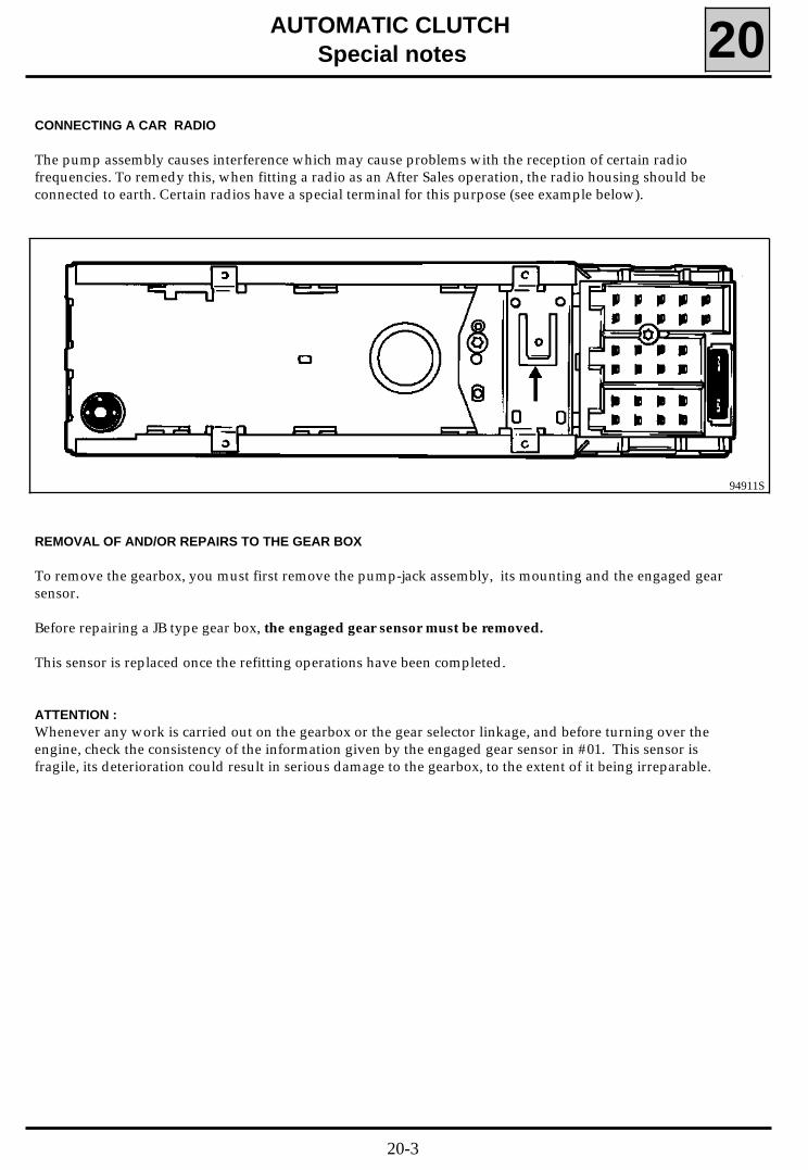
CONNECTING A CAR RADIO
The pump assembly causes interference which may cause problems with the reception of certain radiofrequencies. To remedy this, when fitting a radio as an After Sales operation, the radio housing should beconnected to earth. Certain radios have a special terminal for this purpose (see example below).
REMOVAL OF AND/OR REPAIRS TO THE GEAR BOX
To remove the gearbox, you must first remove the pump-jack assembly, its mounting and the engaged gearsensor.
Before repairing a JB type gear box, the engaged gear sensor must be removed.
This sensor is replaced once the refitting operations have been completed.
ATTENTION :Whenever any work is carried out on the gearbox or the gear selector linkage, and before turning over theengine, check the consistency of the information given by the engaged gear sensor in #01. This sensor isfragile, its deterioration could result in serious damage to the gearbox, to the extent of it being irreparable.
94911S
20-3
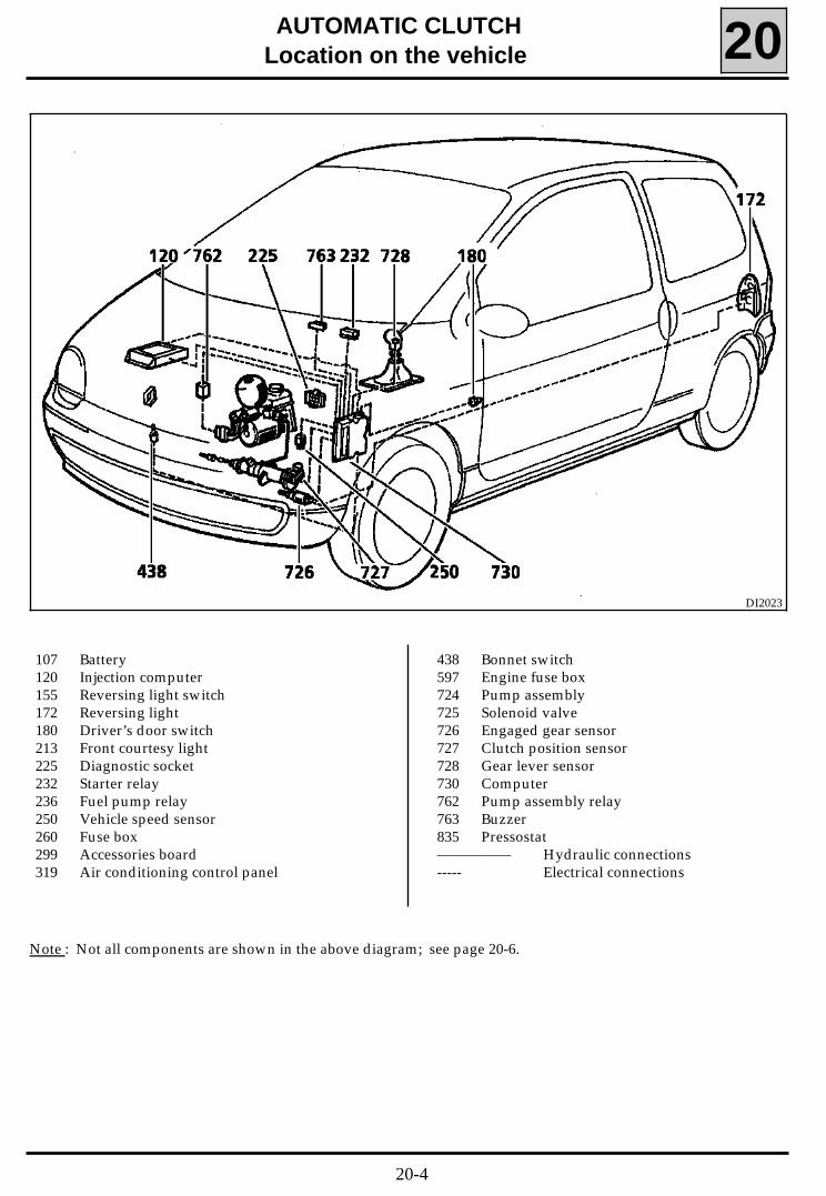
AUTOMATIC CLUTCHLocation on the vehicle 20
107 Battery120 Injection computer155 Reversing light switch172 Reversing light180 Driver’s door switch213 Front courtesy light225 Diagnostic socket232 Starter relay236 Fuel pump relay250 Vehicle speed sensor260 Fuse box299 Accessories board319 Air conditioning control panel
438 Bonnet switch597 Engine fuse box724 Pump assembly725 Solenoid valve726 Engaged gear sensor727 Clutch position sensor728 Gear lever sensor730 Computer762 Pump assembly relay763 Buzzer835 Pressostat————— Hydraulic connections----- Electrical connections
DI2023
Note : Not all components are shown in the above diagram; see page 20-6.
20-4
AUTOMATIC CLUTCHPump-hydraulic jack assembly 20
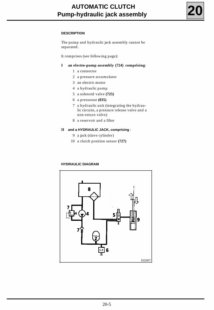
DESCRIPTION
The pump and hydraulic jack assembly cannot beseparated.
It comprises (see following page):
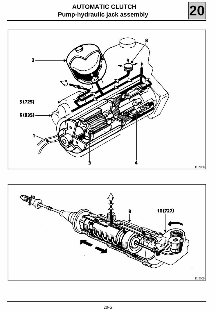
I an electro-pump assembly (724) comprising:1 a connector2 a pressure accumulator3 an electric motor4 a hydraulic pump5 a solenoid valve (725)
6 a pressostat (835)
7 a hydraulic unit (integrating the hydrau-lic circuits, a pressure release valve and anon-return valve)
8 a reservoir and a filter
II and a HYDRAULIC JACK, comprising :9 a jack (slave cylinder)
10 a clutch position sensor (727)
HYDRAULIC DIAGRAM
DI2007
20-5
AUTOMATIC CLUTCHPump-hydraulic jack assembly 20
DI2008
DI2009
20-6
AUTOMATIC CLUTCHPump-hydraulic jack assembly 20
I PUMP ASSEMBLY
1 - 5 track connector
Track A: + before ignition motor feedTrack B : PressostatTrack C : PressostatTrack D: Solenoid valveTrack E : Solenoid valveTerminal for motor electrical earth
2 - Accumulator
The accumulator permits intermittentoperation of the pump motor.
When the accumulator is full, the clutchmay operate through 4 or 5 cycles beforethe accumulator requires refilling.
3 - Motor
The electric motor drives the hydraulicpump.
The computer operates the motor depen-ding on:- the information from the pressostat,- + after ignition information
Feed voltage: 13.5 VAverage current: 7 AMotor current when cold: 25 AResistance : 1 Ω
4 - Pump
This is driven by the electric motor.
It is of an axial type with 5 pistons.
It generates the hydraulic pressure requi-red to supply the jack and fill the accumu-lator.
20-7
AUTOMATIC CLUTCHPump-hydraulic jack assembly 20
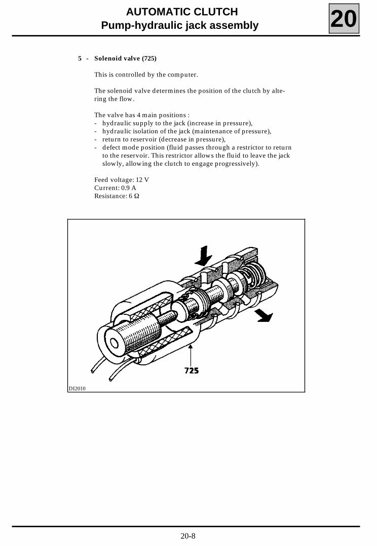
5 - Solenoid valve (725)
This is controlled by the computer.
The solenoid valve determines the position of the clutch by alte-ring the flow.
The valve has 4 main positions :- hydraulic supply to the jack (increase in pressure),- hydraulic isolation of the jack (maintenance of pressure),- return to reservoir (decrease in pressure),- defect mode position (fluid passes through a restrictor to return
to the reservoir. This restrictor allows the fluid to leave the jackslowly, allowing the clutch to engage progressively).
Feed voltage: 12 VCurrent: 0.9 AResistance: 6 Ω
DI2010
20-8
yes no
AUTOMATIC CLUTCHPump-hydraulic jack assembly 20
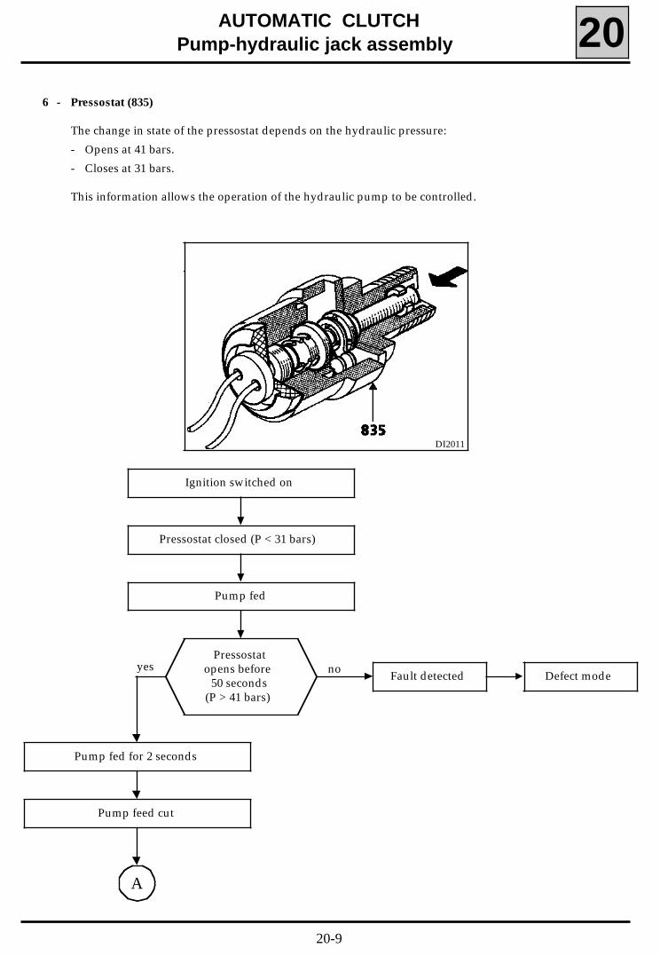
6 - Pressostat (835)
The change in state of the pressostat depends on the hydraulic pressure:
- Opens at 41 bars.
- Closes at 31 bars.
This information allows the operation of the hydraulic pump to be controlled.
Ignition switched on
Pressostat closed (P < 31 bars)
Pump fed
Pressostatopens before
50 seconds(P > 41 bars)
Pump fed for 2 seconds
Fault detected Defect mode
A
Pump feed cut
DI2011
20-9

AUTOMATIC CLUTCHPump-hydraulic jack assembly 20
no yes
Pump fed for 3.6 seconds
Pressostatclosed
(P < 31 bars)
Pump fed for 3.6 seconds
A
yes no
Pressostatopen
(P > 41 bars)Pump feed cut
no yes
Fault detected
Pressostatopen
(P > 41 bars)Pump feed cut
Defect mode
Jack decreases the pressure
20-10
AUTOMATIC CLUTCHPump-hydraulic jack assembly 20
7 - Pressure release valve
This protects the various componentsfrom excess pressure.
This valve opens at 70 bars (the operatingpressure of the system is 41 bars).
8 - Reservoir
This contains the hydraulic fluid.Its size is such that it is able to cope withthe variations in level due to :- the position of the jack,- the fill level of the accumulator,- clutch wear.
To check the level refer to the section"Hydraulic fluid level".
20-11
AUTOMATIC CLUTCHPump-hydraulic jack assembly 20
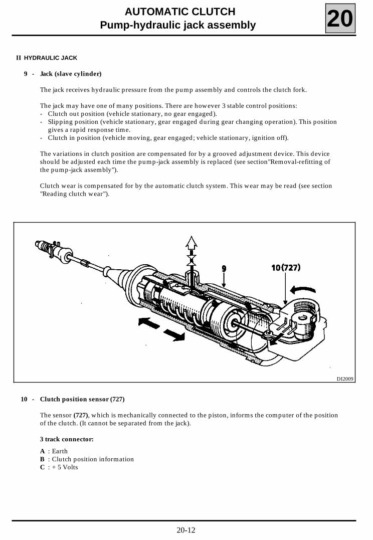
II HYDRAULIC JACK
9 - Jack (slave cylinder)
The jack receives hydraulic pressure from the pump assembly and controls the clutch fork.
The jack may have one of many positions. There are however 3 stable control positions:- Clutch out position (vehicle stationary, no gear engaged).- Slipping position (vehicle stationary, gear engaged during gear changing operation). This position
gives a rapid response time.- Clutch in position (vehicle moving, gear engaged; vehicle stationary, ignition off).
The variations in clutch position are compensated for by a grooved adjustment device. This deviceshould be adjusted each time the pump-jack assembly is replaced (see section"Removal-refitting ofthe pump-jack assembly").
Clutch wear is compensated for by the automatic clutch system. This wear may be read (see section"Reading clutch wear").
10 - Clutch position sensor (727)
The sensor (727), which is mechanically connected to the piston, informs the computer of the positionof the clutch. (It cannot be separated from the jack).
3 track connector:
A : EarthB : Clutch position informationC : + 5 Volts
DI2009
20-12
AUTOMATIC CLUTCHPump-hydraulic jack assembly 20
REMOVAL - REFITTING
Special notes
Apply the handbrake before any operation on thevehicle.
The connectors for the various components mayonly be disconnected when the ignition is off, theengine has stopped completely and the vehicle isstationary.
Before carrying out any operation on the pump-jack assembly discharge the accumulator (to dothis see section"Discharging the accumulator").
It is forbidden to :- separate the pump assembly from the jack,- dismantle the various components of the pump
assembly or the jack (assembly is under pres-sure).
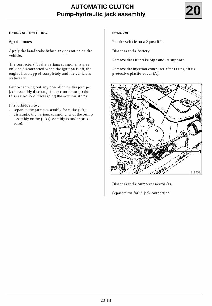
REMOVAL
Put the vehicle on a 2 post lift.
Disconnect the battery.
Remove the air intake pipe and its support.
Remove the injection computer after taking off itsprotective plastic cover (A).
11896R
Disconnect the pump connector (1).
Separate the fork/ jack connection.
20-13
AUTOMATIC CLUTCHPump-hydraulic jack assembly 20
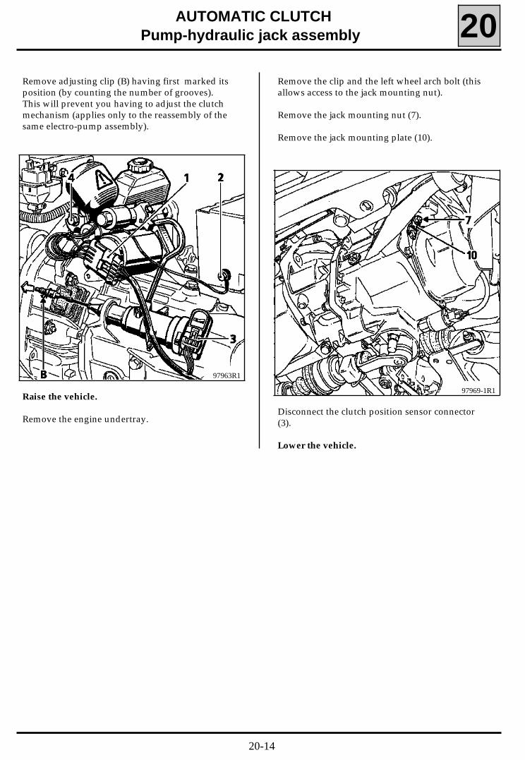
Remove adjusting clip (B) having first marked itsposition (by counting the number of grooves).This will prevent you having to adjust the clutchmechanism (applies only to the reassembly of thesame electro-pump assembly).
97963R1
Raise the vehicle.
Remove the engine undertray.
Remove the clip and the left wheel arch bolt (thisallows access to the jack mounting nut).
Remove the jack mounting nut (7).
Remove the jack mounting plate (10).
97969-1R1
Disconnect the clutch position sensor connector(3).
Lower the vehicle.
20-14
AUTOMATIC CLUTCHPump-hydraulic jack assembly 20
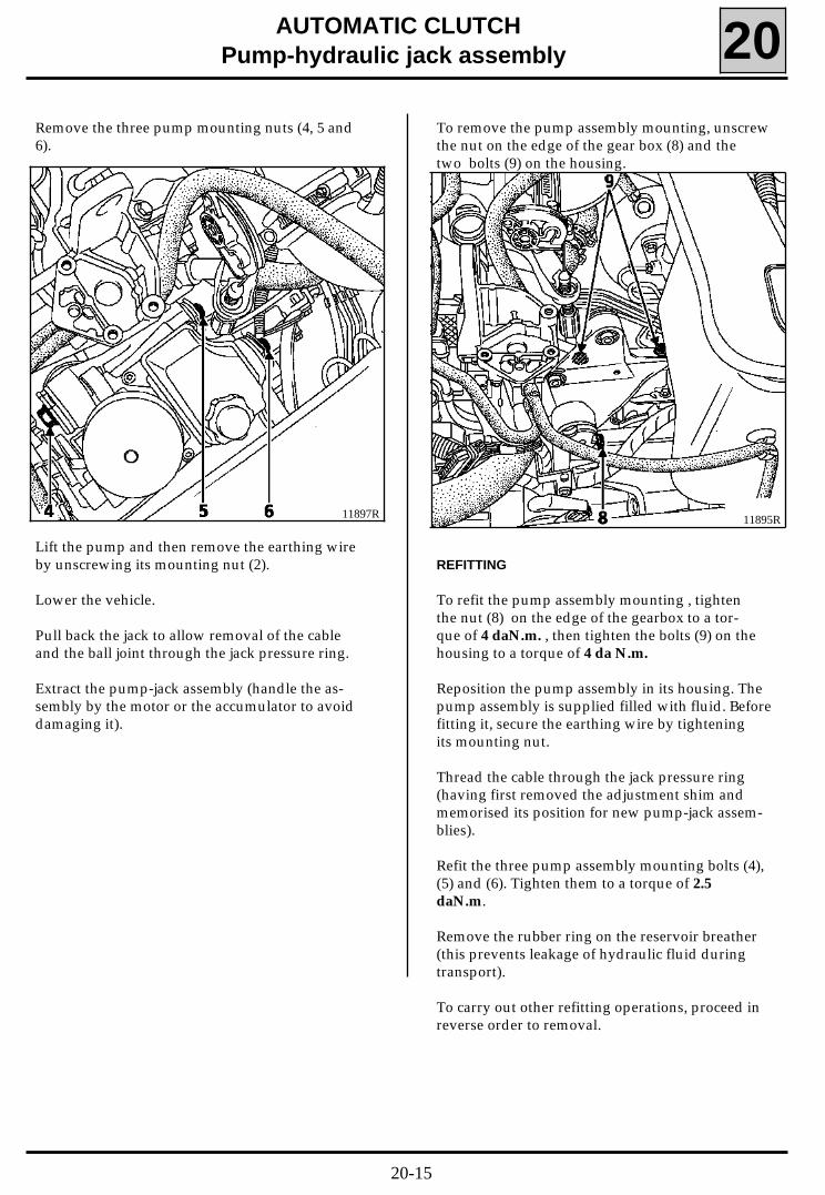
Remove the three pump mounting nuts (4, 5 and6).
Lift the pump and then remove the earthing wireby unscrewing its mounting nut (2).
Lower the vehicle.
Pull back the jack to allow removal of the cableand the ball joint through the jack pressure ring.
Extract the pump-jack assembly (handle the as-sembly by the motor or the accumulator to avoiddamaging it).
11897R
To remove the pump assembly mounting, unscrewthe nut on the edge of the gear box (8) and thetwo bolts (9) on the housing.
11895R
REFITTING
To refit the pump assembly mounting , tightenthe nut (8) on the edge of the gearbox to a tor-que of 4 daN.m. , then tighten the bolts (9) on thehousing to a torque of 4 da N.m.
Reposition the pump assembly in its housing. Thepump assembly is supplied filled with fluid. Beforefitting it, secure the earthing wire by tighteningits mounting nut.
Thread the cable through the jack pressure ring(having first removed the adjustment shim andmemorised its position for new pump-jack assem-blies).
Refit the three pump assembly mounting bolts (4),(5) and (6). Tighten them to a torque of 2.5daN.m.
Remove the rubber ring on the reservoir breather(this prevents leakage of hydraulic fluid duringtransport).
To carry out other refitting operations, proceed inreverse order to removal.
20-15
AUTOMATIC CLUTCHPump-hydraulic jack assembly 20
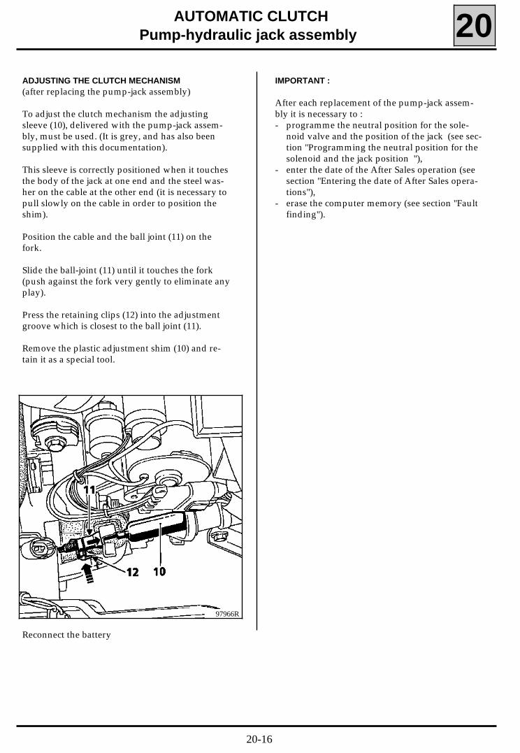
ADJUSTING THE CLUTCH MECHANISM(after replacing the pump-jack assembly)
To adjust the clutch mechanism the adjustingsleeve (10), delivered with the pump-jack assem-bly, must be used. (It is grey, and has also beensupplied with this documentation).
This sleeve is correctly positioned when it touchesthe body of the jack at one end and the steel was-her on the cable at the other end (it is necessary topull slowly on the cable in order to position theshim).
Position the cable and the ball joint (11) on thefork.
Slide the ball-joint (11) until it touches the fork(push against the fork very gently to eliminate anyplay).
Press the retaining clips (12) into the adjustmentgroove which is closest to the ball joint (11).
Remove the plastic adjustment shim (10) and re-tain it as a special tool.
IMPORTANT :
After each replacement of the pump-jack assem-bly it is necessary to :- programme the neutral position for the sole-
noid valve and the position of the jack (see sec-tion "Programming the neutral position for thesolenoid and the jack position "),
- enter the date of the After Sales operation (seesection "Entering the date of After Sales opera-tions"),
- erase the computer memory (see section "Faultfinding").
97966R
Reconnect the battery
20-16
AUTOMATIC CLUTCHAccumulator 20
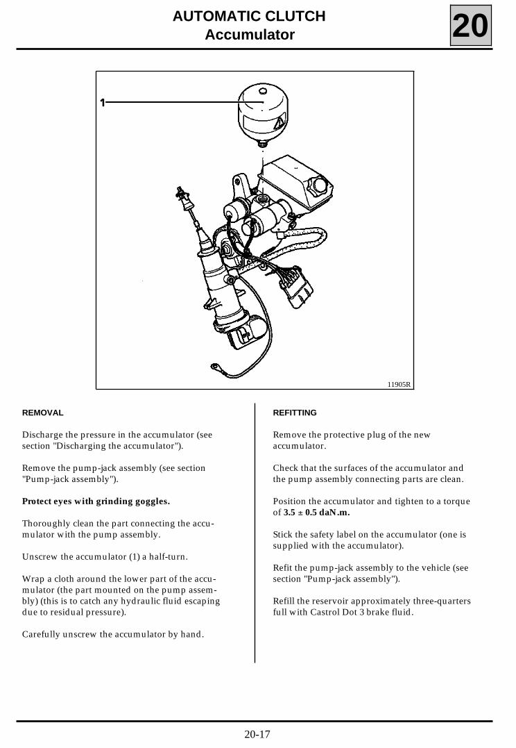
REMOVAL
Discharge the pressure in the accumulator (seesection "Discharging the accumulator").
Remove the pump-jack assembly (see section"Pump-jack assembly").
Protect eyes with grinding goggles.
Thoroughly clean the part connecting the accu-mulator with the pump assembly.
Unscrew the accumulator (1) a half-turn.
Wrap a cloth around the lower part of the accu-mulator (the part mounted on the pump assem-bly) (this is to catch any hydraulic fluid escapingdue to residual pressure).
Carefully unscrew the accumulator by hand.
REFITTING
Remove the protective plug of the newaccumulator.
Check that the surfaces of the accumulator andthe pump assembly connecting parts are clean.
Position the accumulator and tighten to a torqueof 3.5 ± 0.5 daN.m.
Stick the safety label on the accumulator (one issupplied with the accumulator).
Refit the pump-jack assembly to the vehicle (seesection "Pump-jack assembly").
Refill the reservoir approximately three-quartersfull with Castrol Dot 3 brake fluid.
11905R
20-17
AUTOMATIC CLUTCH
Accumulator 20CHECKING THAT THE SYSTEM OPERATES COR-RECTLY
Connect the XR25.
Switch the ignition on and then off again (repeatthe operation 10 times, waiting 10 seconds eachtime the ignition is switched off).
Switch the ignition on. Connect the automaticclutch computer to the XR25 (enter D26).
Fully press down slowly and release the clutch 20times.
Check the level of hydraulic fluid (see section "Hy-draulic fluid level").
Carry out a road test using all the gears.
Recheck the hydraulic fluid level.
Check that no fault is stored in the automaticclutch computer.
Check that there is no leakage at the surfaces ofthe accumulator-pump connection.
20-18
AUTOMATIC CLUTCH
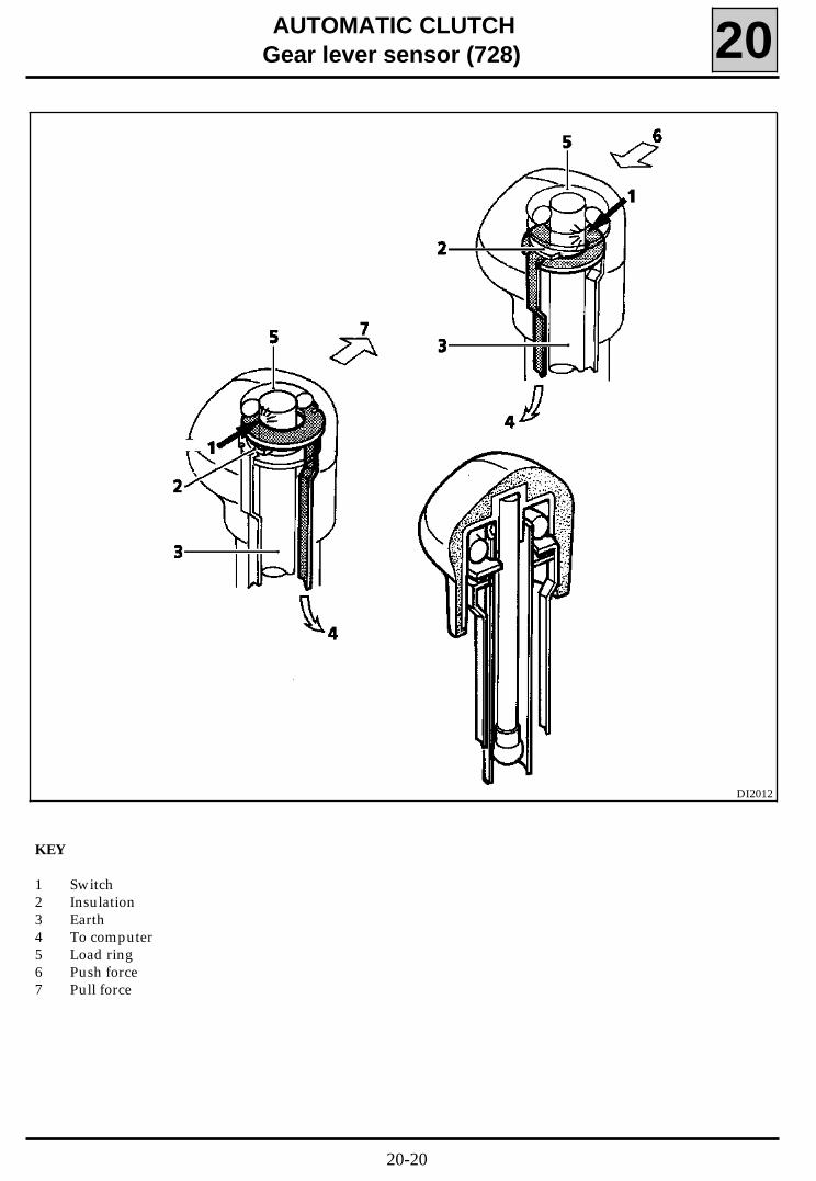
Gear lever sensor (728) 20DESCRIPTION
There are two switches in the gear lever knob:- a pull switch (switch closes when the gear lever is pulled),- a push switch (switch closes when the gear lever is pushed).
A force applied to the gear lever knob by the driver which is greater than a predetermined threshold closesone of the two switches, connecting it to earth.
This information tells the computer that the driver wishes to change gear. If there is a fault with the sensor,the information is taken from the signal from the gear engaged sensor.
When this sensor is replaced, the gears must be programmed (see section "Programming the gears")
3 track connector:
A : Push informationB : Pull informationC : Earth
20-19
AUTOMATIC CLUTCHGear lever sensor (728) 20
KEY
1 Switch2 Insulation3 Earth4 To computer5 Load ring6 Push force7 Pull force
DI2012
20-20
AUTOMATIC CLUTCHGear lever sensor (728) 20
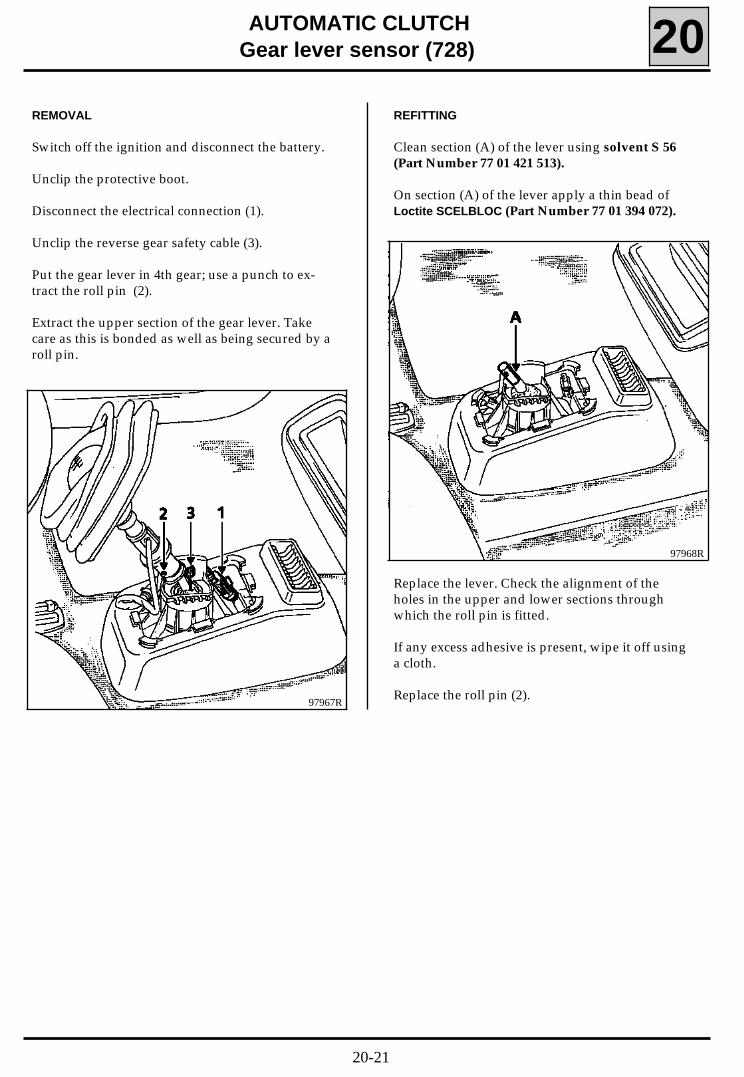
REMOVAL
Switch off the ignition and disconnect the battery.
Unclip the protective boot.
Disconnect the electrical connection (1).
Unclip the reverse gear safety cable (3).
Put the gear lever in 4th gear; use a punch to ex-tract the roll pin (2).
Extract the upper section of the gear lever. Takecare as this is bonded as well as being secured by aroll pin.
Replace the lever. Check the alignment of theholes in the upper and lower sections throughwhich the roll pin is fitted.
If any excess adhesive is present, wipe it off usinga cloth.
Replace the roll pin (2).97967R
97968R
REFITTING
Clean section (A) of the lever using solvent S 56(Part Number 77 01 421 513).
On section (A) of the lever apply a thin bead ofLoctite SCELBLOC (Part Number 77 01 394 072).
20-21
AUTOMATIC CLUTCHGear lever sensor (728) 20
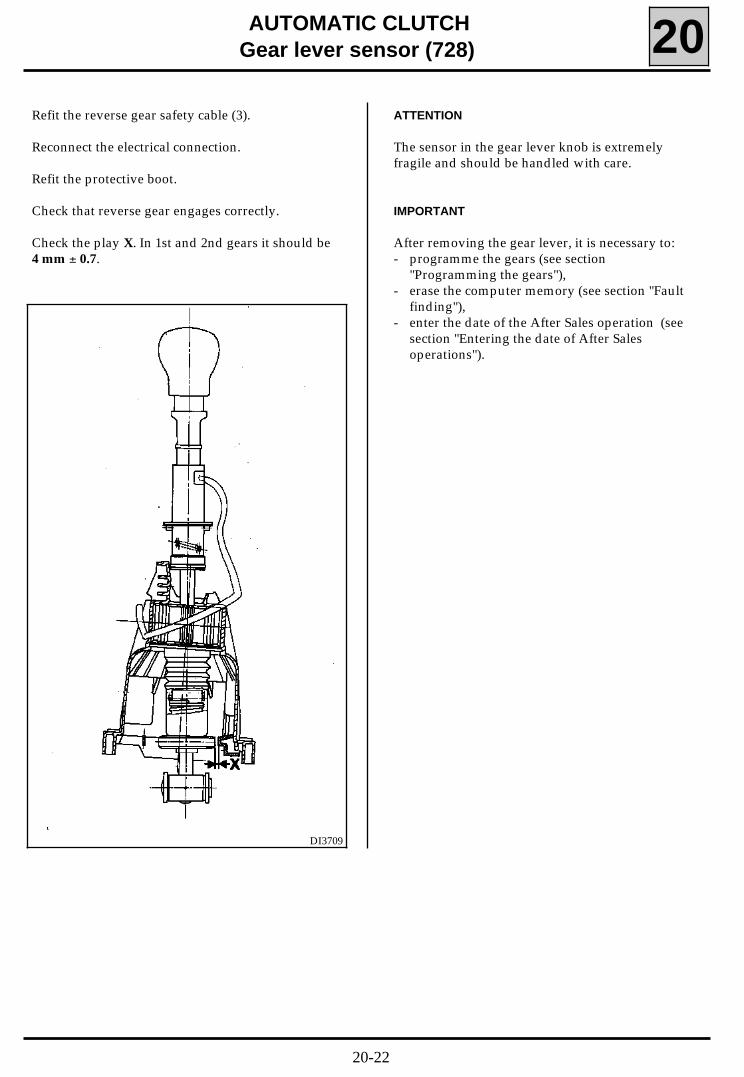
Refit the reverse gear safety cable (3).
Reconnect the electrical connection.
Refit the protective boot.
Check that reverse gear engages correctly.
Check the play X. In 1st and 2nd gears it should be4 mm ± 0.7.
ATTENTION
The sensor in the gear lever knob is extremelyfragile and should be handled with care.
IMPORTANT
After removing the gear lever, it is necessary to:- programme the gears (see section
"Programming the gears"),- erase the computer memory (see section "Fault
finding"),- enter the date of the After Sales operation (see
section "Entering the date of After Salesoperations").
DI3709
20-22
AUTOMATIC CLUTCHEngaged gear sensor (726) 20
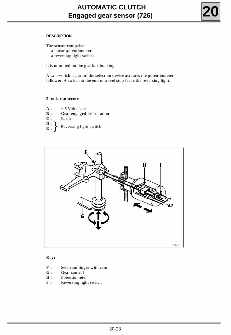
DESCRIPTION
The sensor comprises:- a linear potentiometer,- a reversing light switch
It is mounted on the gearbox housing.
A cam which is part of the selection device actuates the potentiometerfollower. A switch at the end of travel stop feeds the reversing light.
5 track connector:
A : + 5 Volts feedB : Gear engaged informationC : EarthD :E : Reversing light switch
DI2013
Key:
F : Selection finger with camG : Gear controlH : PotentiometerI : Reversing light switch
20-23

AUTOMATIC CLUTCHEngaged gear sensor (726) 20
The engaged gear sensor optimises the operationof the automatic clutch by informing the compu-ter of:- the beginning and end of gear changing opera-
tions,- the gear engaged.
For each gear, the computer has a predeterminedmemorised value range. If the information recei-ved does not correspond to the set range, thecomputer is able to initiate a defect mode and towarn the driver with a buzzer message.
To determine the difference between gears:- from 1st to 2nd- from 3rd to 4th
the computer uses the "push or pull" information.
REMOVAL
Put the vehicle on a 2 post lift.
Switch the ignition off and disconnect the battery.
Lift the vehicle.
Remove the engine undertray.
Drain the gearbox (plug 1)
97969R
GEAR SELECTEDPredetermined gear
range (no units) valuebetween 0 and 255
Neutral 113 - 142
1st - 2nd 147 - 200
3rd - 4th 72 - 115
5th 12 - 71
Reverse 199 - 242
Disconnect the engaged gear sensor.
Unscrew the sensor (726).
REFITTING
Screw the engaged gear sensor (726) back intoposition using Loctite FRENETANCH. Tighten it toa torque of 2 daN.m.
Reconnect the connector to the sensor (726).
Fill the gear box and check the level (plug 2). Thelevel is measured by overflow.
Refit the engine undertray.
IMPORTANT :
After removing the engaged gear sensor it isnecessary to:- programme the gears (see section
"Programming the gears"),- erase the computer memory (see section "Fault
finding"),- enter the date of the After Sales operation (see
section "Entering the date of After Salesoperations").
20-24
AUTOMATIC CLUTCH
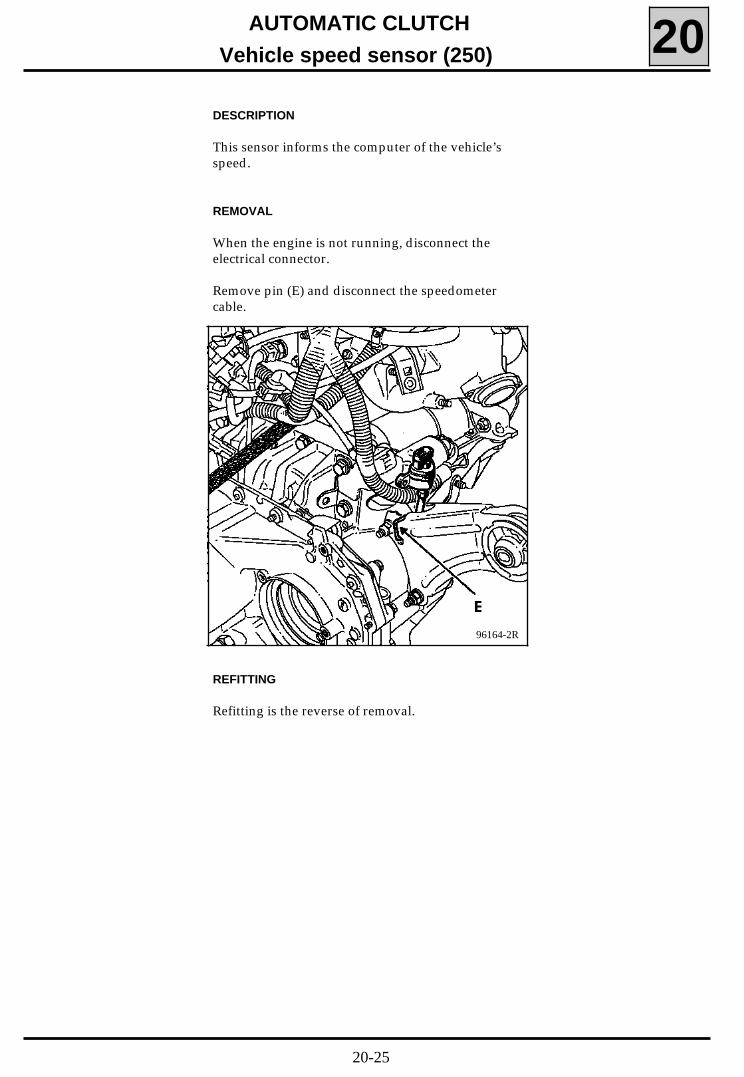
Vehicle speed sensor (250) 20DESCRIPTION
This sensor informs the computer of the vehicle’sspeed.
REMOVAL
When the engine is not running, disconnect theelectrical connector.
Remove pin (E) and disconnect the speedometercable.
REFITTING
Refitting is the reverse of removal.
96164-2R
20-25
Accelerator position information
AUTOMATIC CLUTCH
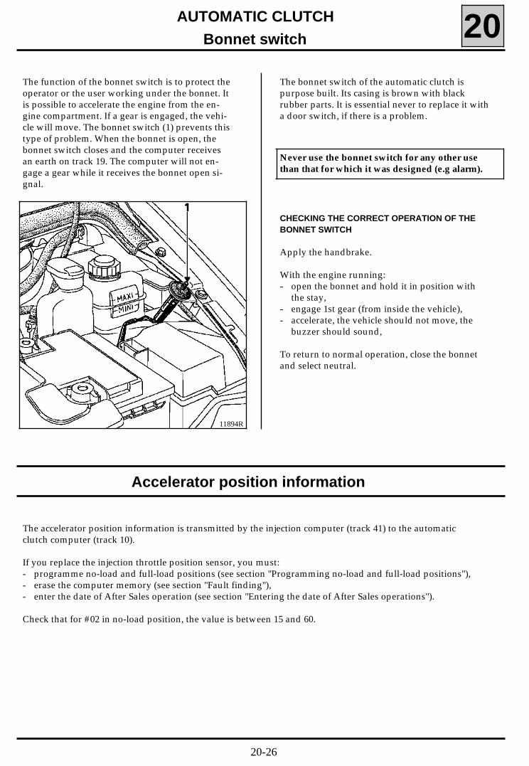
Bonnet switch 20The function of the bonnet switch is to protect theoperator or the user working under the bonnet. Itis possible to accelerate the engine from the en-gine compartment. If a gear is engaged, the vehi-cle will move. The bonnet switch (1) prevents thistype of problem. When the bonnet is open, thebonnet switch closes and the computer receivesan earth on track 19. The computer will not en-gage a gear while it receives the bonnet open si-gnal.
The bonnet switch of the automatic clutch ispurpose built. Its casing is brown with blackrubber parts. It is essential never to replace it witha door switch, if there is a problem.
11894R
Never use the bonnet switch for any other usethan that for which it was designed (e.g alarm).
CHECKING THE CORRECT OPERATION OF THEBONNET SWITCH
Apply the handbrake.
With the engine running:- open the bonnet and hold it in position with
the stay,- engage 1st gear (from inside the vehicle),- accelerate, the vehicle should not move, the
buzzer should sound,
To return to normal operation, close the bonnetand select neutral.
The accelerator position information is transmitted by the injection computer (track 41) to the automaticclutch computer (track 10).
If you replace the injection throttle position sensor, you must:- programme no-load and full-load positions (see section "Programming no-load and full-load positions"),- erase the computer memory (see section "Fault finding"),- enter the date of After Sales operation (see section "Entering the date of After Sales operations").
Check that for #02 in no-load position, the value is between 15 and 60.
20-26
AUTOMATIC CLUTCHEngine speed sensor (120) 20
DESCRIPTION
This information is provided by the injectioncomputer.
The information is taken from the fuel pump re-lay.
Air conditioning information (319)
DESCRIPTION
The air conditioning computer provides the infor-mation:
- 12 Volts : compressor engaged- 0 Volt : compressor not engaged
to the injection computer and the automaticclutch computer on track 17.
The injection computer uses this information tomodify its reference value for the idle speed.
The automatic clutch computer uses this informa-tion to determine whether a change in the enginespeed is due to a change in operation of the airconditioning compressor or an action by the dri-ver.
Door switch (180)
DESCRIPTION
The door switch is used for safety reasons. Thecomputer operates the buzzer when the follo-wing information is received :- driver’s door open,- gear engaged,- engine running.
This warning is given to remind the driver to selectneutral before leaving the vehicle.
The driver’s door switch earths track 25 on thecomputer when the door is open.
20-27
AUTOMATIC CLUTCHComputer (730) 20
IMPORTANT :
Following replacement of the computer it is necessary to:- programme the full-load and no-load positions (see section "Programming the full-load and no-load posi-
tions"),- programme the gears (see section "Programming the gears"),- enter the date of the After Sales operation (see section "Entering the date of After Sales operations").
Programming of the neutral position for the solenoid and the position of the jack occurs automatically whenthe ignition is switched on. When programming is complete, the buzzer will beep. The values are stored 10seconds after switching the ignition off.
If bargraph 10 RH side remains illuminated after the above have been programmed (2 dEF for *30), it meansthat the computer has a new function enabling the clutch slip point to be programmed (see section"Programming neutral position for the solenoid and the jack position").
DI2024
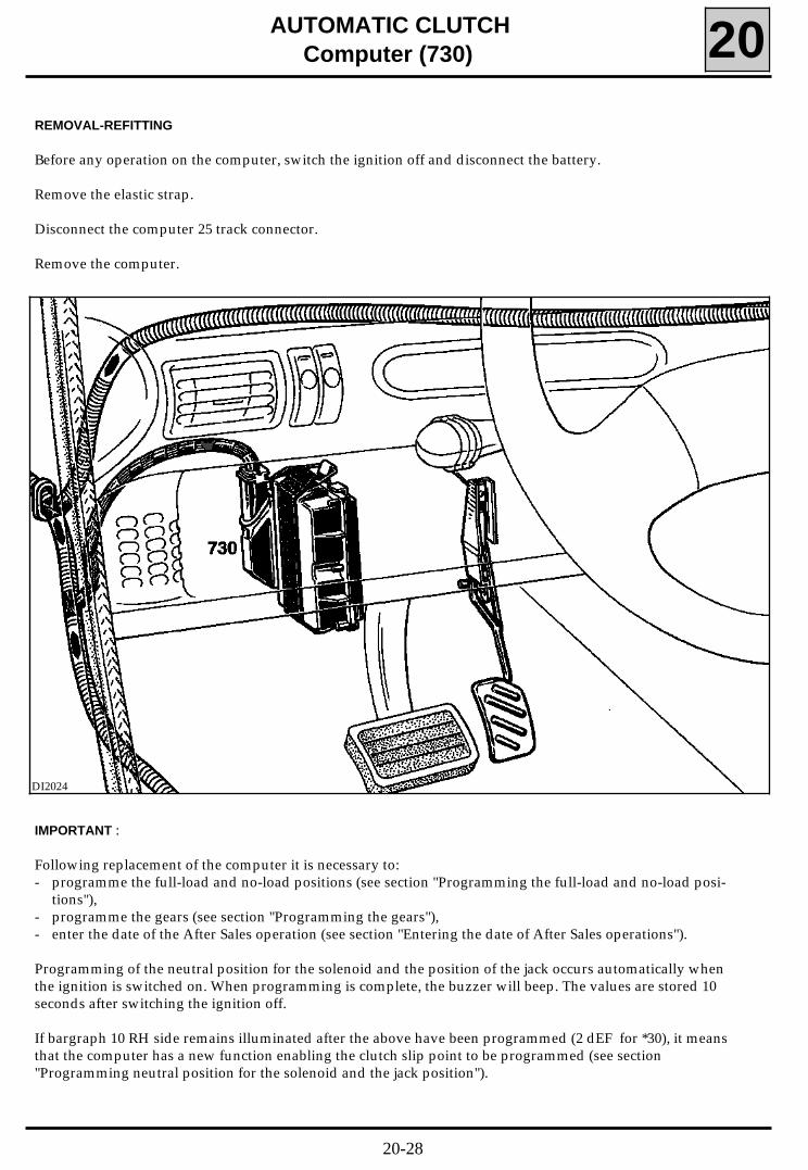
REMOVAL-REFITTING
Before any operation on the computer, switch the ignition off and disconnect the battery.
Remove the elastic strap.
Disconnect the computer 25 track connector.
Remove the computer.
20-28
AUTOMATIC CLUTCHComputer (730) 20
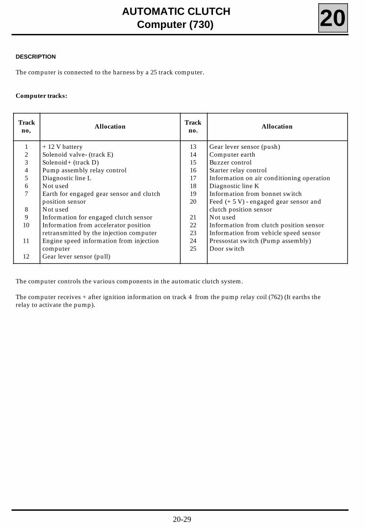
DESCRIPTION
The computer is connected to the harness by a 25 track computer.
Computer tracks:
Trackno,
AllocationTrack
no.Allocation
1234567
89
10
11
12
+ 12 V batterySolenoid valve- (track E)Solenoid+ (track D)Pump assembly relay controlDiagnostic line LNot usedEarth for engaged gear sensor and clutchposition sensorNot usedInformation for engaged clutch sensorInformation from accelerator positionretransmitted by the injection computerEngine speed information from injectioncomputerGear lever sensor (pull)
1314151617181920
2122232425
Gear lever sensor (push)Computer earthBuzzer controlStarter relay controlInformation on air conditioning operationDiagnostic line KInformation from bonnet switchFeed (+ 5 V) - engaged gear sensor andclutch position sensorNot usedInformation from clutch position sensorInformation from vehicle speed sensorPressostat switch (Pump assembly)Door switch
The computer controls the various components in the automatic clutch system.
The computer receives + after ignition information on track 4 from the pump relay coil (762) (It earths therelay to activate the pump).
20-29
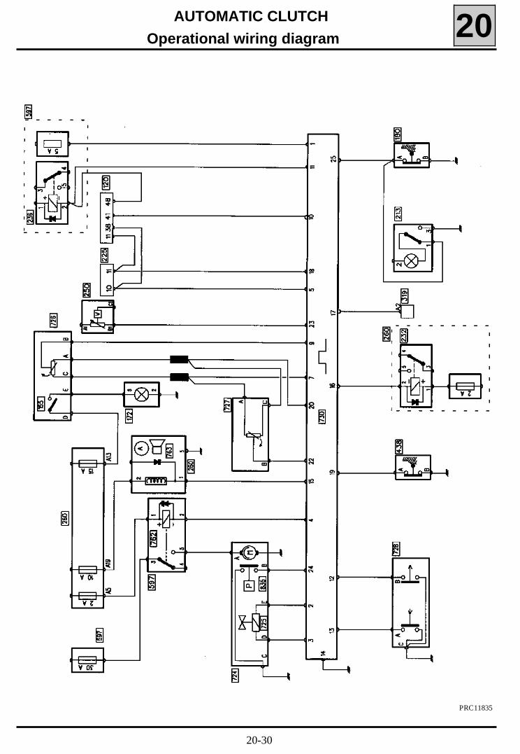
AUTOMATIC CLUTCH
Operational wiring diagram 20
PRC11835
20-30
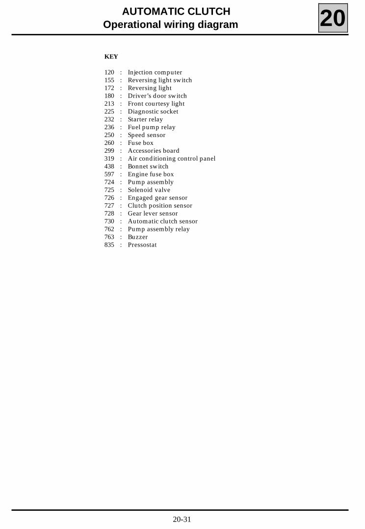
AUTOMATIC CLUTCHOperational wiring diagram 20KEY
120 : Injection computer155 : Reversing light switch172 : Reversing light180 : Driver’s door switch213 : Front courtesy light225 : Diagnostic socket232 : Starter relay236 : Fuel pump relay250 : Speed sensor260 : Fuse box299 : Accessories board319 : Air conditioning control panel438 : Bonnet switch597 : Engine fuse box724 : Pump assembly725 : Solenoid valve726 : Engaged gear sensor727 : Clutch position sensor728 : Gear lever sensor730 : Automatic clutch sensor762 : Pump assembly relay763 : Buzzer835 : Pressostat
20-31
AUTOMATIC CLUTCH
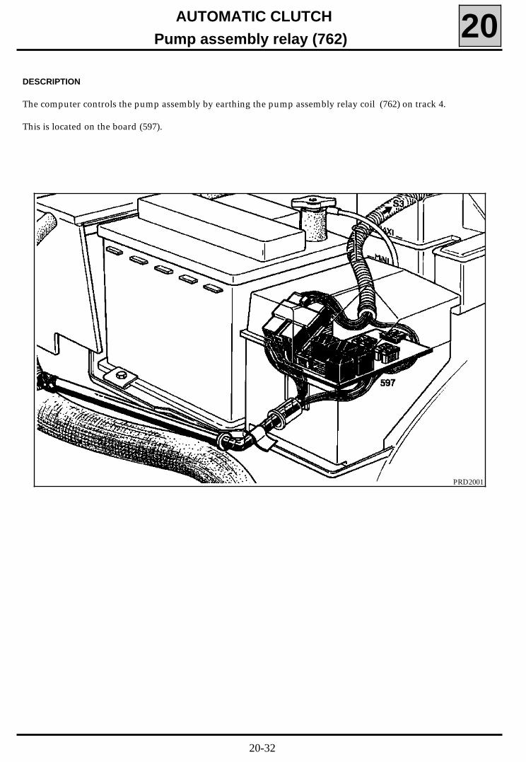
Pump assembly relay (762) 20DESCRIPTION
The computer controls the pump assembly by earthing the pump assembly relay coil (762) on track 4.
This is located on the board (597).
PRD2001
20-32
PRD2002
AUTOMATIC CLUTCHStarter relay (232) 20
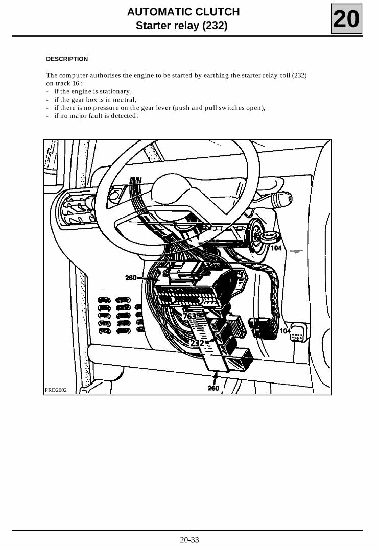
DESCRIPTION
The computer authorises the engine to be started by earthing the starter relay coil (232)on track 16 :- if the engine is stationary,- if the gear box is in neutral,- if there is no pressure on the gear lever (push and pull switches open),- if no major fault is detected.
20-33
AUTOMATIC CLUTCHBuzzer (763) 20
DESCRIPTION
The computer uses the buzzer to alert the driverin the case of :- manoeuvres which are dangerous for the clutch
or the driver. It must be emphasised that thedriver must heed the message informing himthat the vehicle must not be left with the en-gine running and a gear engaged.
- faults being detected.
Refer to the section "Fault finding" for informa-tion on the audible messages given and their mea-ning.
The computer controls the buzzer on track 15.
If the connection between the buzzer and compu-ter track 15 is cut, the buzzer is sounded conti-nuously until the electrical wiring is repaired (forthe location on the vehicle, see the previouspage).
20-34
AUTOMATIC CLUTCHOperation 20
VEHICLE AND ENGINE STATIONARY (STOPPED)
When the vehicle and engine are stopped, theclutch is engaged (clutch locked).
When the ignition is switched on, the automaticclutch computer makes the following checks:
- push / pull switch not activated,
- engine not running,
- no critical fault was detected during the last pe-riod of operation.
If the checks are correct, the computer earths thecoil of the pump motor relay (762). The pumpthen generates hydraulic pressure.
To be able to start the engine, neutral must be en-gaged. If neutral is engaged, the computer usesthe solenoid to :
- control the clutch,
- earth the coil of the starter relay (232) (the en-gine may be started before there is sufficientpressure to completely disengage the clutch).
If the vehicle has been left with a gear engaged(on a slope for example), the above checks arecarried out and the system is activated.
However the clutch is disengaged only when thedriver exerts a pressure on the gear lever . Thispressure allows the clutch to be disengaged andallows neutral to be selected. The engine maythen be started.
VEHICLE STATIONARY, ENGINE RUNNING
The clutch is engaged (clutch locked) when the ve-hicle is:
- in neutral,- stationary - parked,- engine running at idle speed.
The clutch is disengaged (clutch slip) when:
- there is a gear engaged,- stationary -parked,- engine running at idle speed.
In this position, the vehicle is immobilised.
STARTING THE VEHICLE MOVING
To start the vehicle the driver selects a gear.
To begin the clutch operation phase the computerrequires two pieces of information:
- accelerator pedal position greater than a pre-determined threshold,
- engine speed greater than 400 rpm above thememorised idle speed (the engine speed variesaccording to engine temperature; warm en-gine, it is 740 rpm). An engine speed of 740 +400, or 1140 rpm is therefore required.
The automatic clutch computer memorises theidle speed when the vehicle is stationary, enginerunning.
When the air conditioning is selected, the injec-tion computer specifies an idle speed of 880 rpmfor a warm engine. In order to be able to differen-tiate between an increase in engine speed causedby the air conditioning computer or one reques-ted by the driver, the automatic clutch computerreceives air conditioning selected information.
If the gear selected, ie, 2nd or 3rd, to start the ve-hicle moving causes excessive slip, the computersounds the buzzer during the period of slippage.
To reduce clutch slip, the automatic clutch compu-ter compares engine speed information with vehi-cle speed information according to the gear enga-ged.
If a stationary vehicle with a gear engaged andthe engine running is left to descend a slope andgain speed, at a given speed the clutch will be en-gaged (clutch locked) progressively.
20-35
AUTOMATIC CLUTCHOperation 20
CHANGING UP THE GEARS
To change gear, the driver applies a pressure tothe gear lever either by pushing or pulling it, andreleases the pressure at the accelerator pedal atthe same time. These actions cause the clutch tobe disengaged (clutch slip) and a new gear to beselected.
The end of the gear changing operation is detec-ted when the signal from the engaged gear sen-sor lies within a range allocated to a given gear.
From this moment on the clutch is once more en-gaged (clutch locked).
No account is taken of pressure applied to thegear lever in the same direction as the last pres-sure to change gear, and this will not cause theclutch to be disengaged. In addition, the pressureexerted by a driver’s hand left on the gear leverknob inadvertently is not sufficient to earth oneof the two switches. These two features preventthe clutch from operating at the incorrect mo-ment.
CHANGING DOWN THE GEARS
This operation is carried out in the same manneras changing up, described above (pressure is ap-plied to the gear lever knob, pressure at the acce-lerator pedal is released and the gear lever is mo-ved to the required position). If the driver wishesto increase the gear changing comfort, and is usedto increasing the engine speed slightly before se-lecting a lower gear, this manoeuvre may be car-ried out by accelerating when the gear lever is inneutral (double de-clutching).
If the driver selects a gear which may causeover-revving of the engine (example : changingfrom 5th to 2nd), the clutch is engaged in acontrolled manner to limit engine speed (6,000rpm for petrol engines).
The clutch will slip until the vehicle speed and en-gine speed are compatible for the gear selected.
The driver is warned by the buzzer.
STOPPING AFTER DRIVING
When the vehicle stops, the clutch disengages tostop the engine from stalling.
If the driver takes his foot off the accelerator pe-dal the vehicle is slowed by engine braking untilthe memorised idle speed plus 200 rpm is reached.From this moment, the clutch begins to slip.
SWITCHING THE IGNITION OFF
After turning the ignition key to the "Stop" posi-tion, the computer remains operational for a fewseconds to carry out the following functions:- Storage of faults noted previously (or present in
the system) in the permanent memory.- Maintenance of the clutch in the disengaged
(clutch slip) position for a short period to allowthe engine to stop.
- Authorisation for the clutch to engage (clutchlock) progressively.
20-36
AUTOMATIC CLUTCHOperation 20
PUSH STARTING THE VEHICLE
This assumes that the battery voltage is within ac-ceptable limits > 7 volts.
If the ignition key is put in the "Running" positionthe automatic clutch system is able to reach ope-rating pressure and disengage the clutch if thegear box is in neutral and a gear needs to be en-gaged.
If the battery does not have sufficient voltage, theclutch will not disengage. It is then inadvisable topush the vehicle or tow it in order to start it.
If the clutch is disengaged (clutch lslip) and thegear box is in neutral, the vehicle may be pushedor towed. At a speed of 4 mph (7 km/h) a beepwill be heard which means that 2nd gear may beselected, causing the clutch to engage and the en-gine to be driven. Once the engine has started,neutral may be selected and the engine speedmay be increased as necessary.
OPERATION IN DEFECT MODE
The vehicle may still be driven even if minor faultshave been detected. In the case of intermittentminor faults, the computer is programmed to re-sume normal operation as soon as the faults havedisappeared.
If there is a major fault, the system turns off. Inmost cases this is seen by the slow engagement ofthe clutch (the clutch remains engaged (clutchlocked) if it was already in that position).However, under certain circumstances: if the vehi-cle is moving at a speed less than 2.5 mph (4km/h), and if the accelerator pedal is depressed byless than 10% of its complete travel, the clutchwill disengage (slip).
If the system’s electrical feed is accidentally cut,the clutch will engage (lock). The time taken forthe clutch/system to reactivate is defined by thepassage of hydraulic fluid through a restrictor.
If a fault was noted during the last check, whenthe ignition is switched on again, the buzzer willsound three times. If the fault does not reappearduring this check, the warning will be cancelledwhen the ignition is next switched on.
SPECIAL NOTE
The system compensates for clutch wear.
To read this wear refer to section "Reading clutchwear".
20-37
AUTOMATIC CLUTCHClutch identification 20
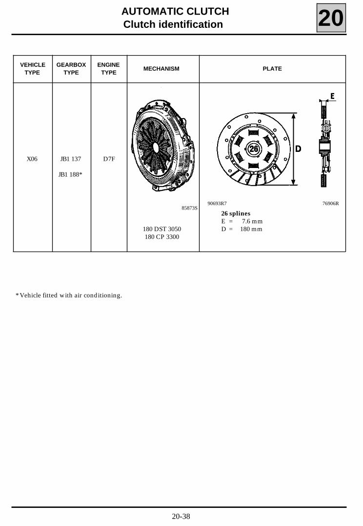
VEHICLETYPE
GEARBOXTYPE
ENGINETYPE
MECHANISM PLATE
X06 JB1 137
JB1 188*
D7F
180 DST 3050180 CP 3300
26 splinesE = 7.6 mmD = 180 mm
85873S90693R7 76906R
* Vehicle fitted with air conditioning.
20-38
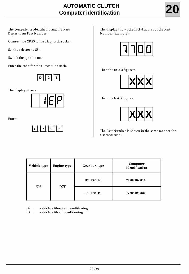
The display shows the first 4 figures of the PartNumber (example):
Then the next 3 figures:
Then the last 3 figures:
The Part Number is shown in the same manner fora second time.
AUTOMATIC CLUTCHComputer identification 20
The computer is identified using the PartsDepartment Part Number.
Connect the XR25 to the diagnostic socket.
Set the selector to S8.
Switch the ignition on.
Enter the code for the automatic clutch.
The display shows:
Enter:
Vehicle type Engine type Gear box typeComputer
identification
X06 D7F
JB1 137 (A)
JB1 188 (B)
77 00 102 016
77 00 103 880
D 2 6
G 7 0 *
•
XXX
XXX
A : vehicle without air conditioningB : vehicle with air conditioning
20-39
AUTOMATIC CLUTCHHydraulic fluid level 20
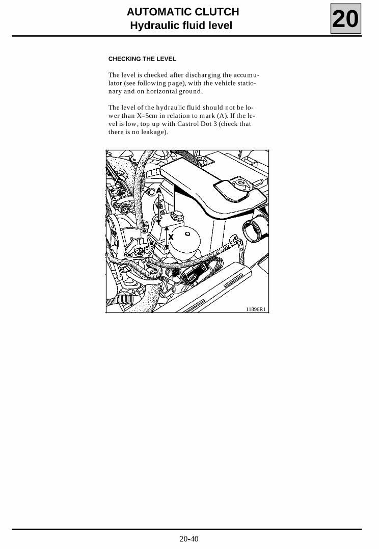
CHECKING THE LEVEL
The level is checked after discharging the accumu-lator (see following page), with the vehicle statio-nary and on horizontal ground.
The level of the hydraulic fluid should not be lo-wer than X=5cm in relation to mark (A). If the le-vel is low, top up with Castrol Dot 3 (check thatthere is no leakage).
11896R1
20-40
AUTOMATIC CLUTCH
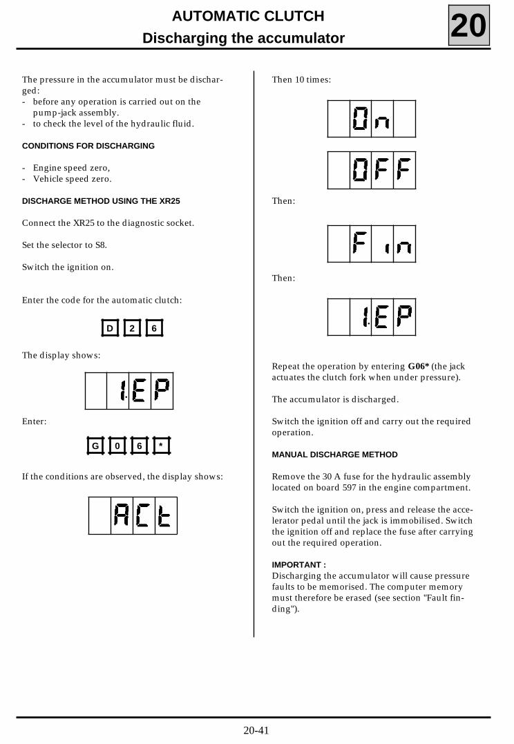
Discharging the accumulator 20The pressure in the accumulator must be dischar-ged:- before any operation is carried out on the
pump-jack assembly.- to check the level of the hydraulic fluid.
CONDITIONS FOR DISCHARGING - Engine speed zero, - Vehicle speed zero.
DISCHARGE METHOD USING THE XR25
Connect the XR25 to the diagnostic socket.
Set the selector to S8. Switch the ignition on.
Enter the code for the automatic clutch:
The display shows:
Enter:
If the conditions are observed, the display shows:
Then 10 times:
Then:
Then:
Repeat the operation by entering G06* (the jackactuates the clutch fork when under pressure).
The accumulator is discharged.
Switch the ignition off and carry out the requiredoperation.
MANUAL DISCHARGE METHOD
Remove the 30 A fuse for the hydraulic assemblylocated on board 597 in the engine compartment.
Switch the ignition on, press and release the acce-lerator pedal until the jack is immobilised. Switchthe ignition off and replace the fuse after carryingout the required operation.
IMPORTANT :Discharging the accumulator will cause pressurefaults to be memorised. The computer memorymust therefore be erased (see section "Fault fin-ding").
D 2 6
G 0 6 *
•
•
20-41
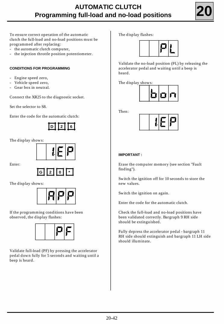
AUTOMATIC CLUTCHProgramming full-load and no-load positions 20
To ensure correct operation of the automaticclutch the full-load and no-load positions must beprogrammed after replacing:- the automatic clutch computer,- the injection throttle position potentiometer.
CONDITIONS FOR PROGRAMMING
- Engine speed zero,- Vehicle speed zero,- Gear box in neutral.
Connect the XR25 to the diagnostic socket.
Set the selector to S8.
Enter the code for the automatic clutch:
The display shows:
Enter:
The display shows:
If the programming conditions have beenobserved, the display flashes:
Validate full-load (PF) by pressing the acceleratorpedal down fully for 5 seconds and waiting until abeep is heard.
The display flashes:
Validate the no-load position (PL) by releasing theaccelerator pedal and waiting until a beep isheard.
The display shows:
Then:
IMPORTANT :
Erase the computer memory (see section "Faultfinding").
Switch the ignition off for 10 seconds to store thenew values.
Switch the ignition on again.
Enter the code for the automatic clutch.
Check the full-load and no-load positions havebeen validated correctly. Bargraph 9 RH sideshould be extinguished.
Fully depress the accelerator pedal - bargraph 11RH side should extinguish and bargraph 11 LH sideshould illuminate.
D 2 6
G 2 0 *
•
•
20-42
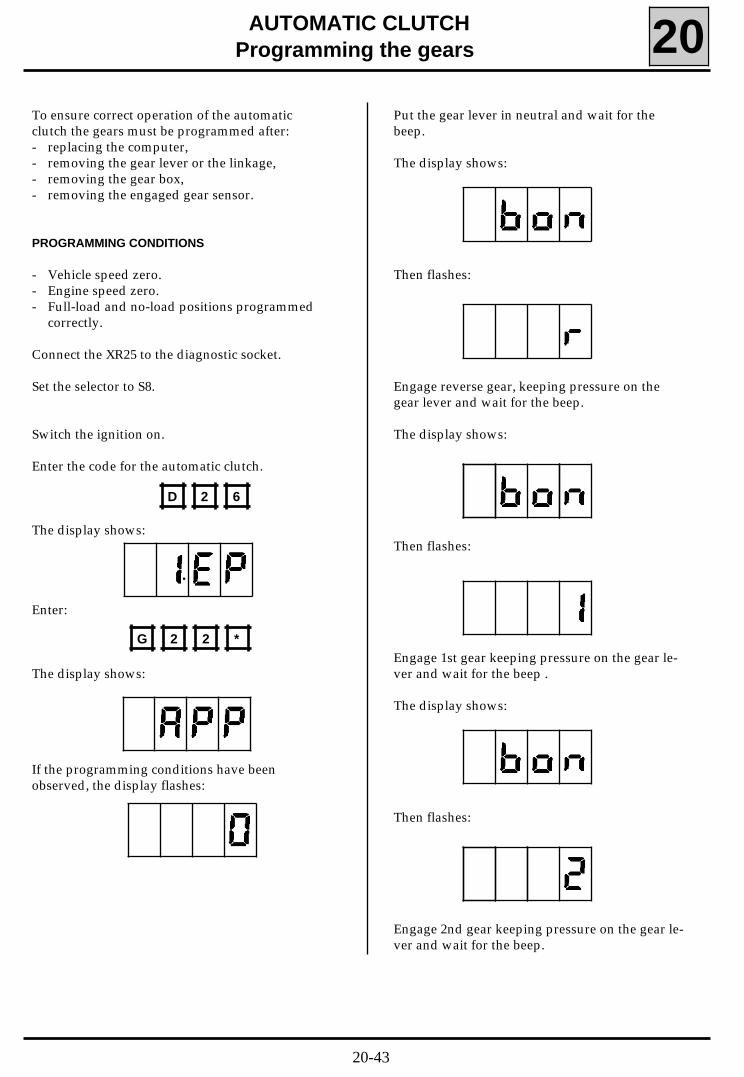
AUTOMATIC CLUTCHProgramming the gears 20
To ensure correct operation of the automaticclutch the gears must be programmed after:- replacing the computer,- removing the gear lever or the linkage,- removing the gear box,- removing the engaged gear sensor.
PROGRAMMING CONDITIONS
- Vehicle speed zero.- Engine speed zero.- Full-load and no-load positions programmed
correctly.
Connect the XR25 to the diagnostic socket.
Set the selector to S8.
Switch the ignition on.
Enter the code for the automatic clutch.
The display shows:
Enter:
The display shows:
If the programming conditions have beenobserved, the display flashes:
Put the gear lever in neutral and wait for thebeep.
The display shows:
Then flashes:
Engage reverse gear, keeping pressure on thegear lever and wait for the beep.
The display shows:
Then flashes:
Engage 1st gear keeping pressure on the gear le-ver and wait for the beep .
The display shows:
Then flashes:
Engage 2nd gear keeping pressure on the gear le-ver and wait for the beep.
D 2 6
G 2 2 *
•
20-43
AUTOMATIC CLUTCHProgramming the gears 20
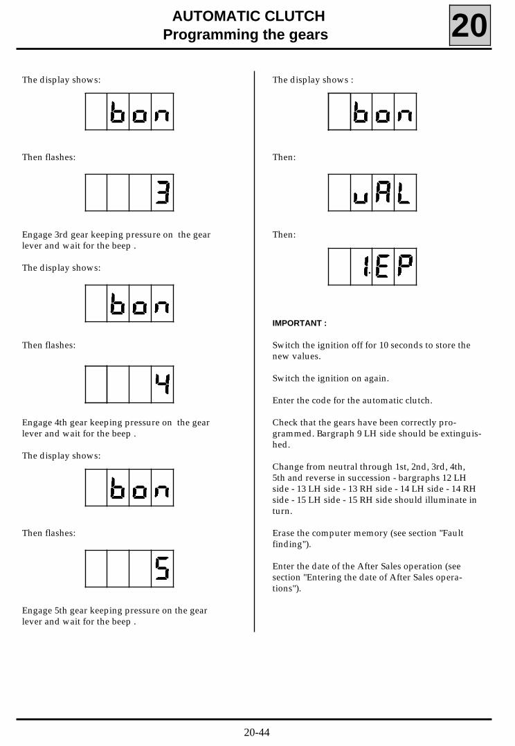
The display shows:
Then flashes:
Engage 3rd gear keeping pressure on the gearlever and wait for the beep .
The display shows:
Then flashes:
Engage 4th gear keeping pressure on the gearlever and wait for the beep .
The display shows:
Then flashes:
Engage 5th gear keeping pressure on the gearlever and wait for the beep .
The display shows :
Then:
Then:
IMPORTANT :
Switch the ignition off for 10 seconds to store thenew values.
Switch the ignition on again.
Enter the code for the automatic clutch.
Check that the gears have been correctly pro-grammed. Bargraph 9 LH side should be extinguis-hed.
Change from neutral through 1st, 2nd, 3rd, 4th,5th and reverse in succession - bargraphs 12 LHside - 13 LH side - 13 RH side - 14 LH side - 14 RHside - 15 LH side - 15 RH side should illuminate inturn.
Erase the computer memory (see section "Faultfinding").
Enter the date of the After Sales operation (seesection "Entering the date of After Sales opera-tions").
•
20-44
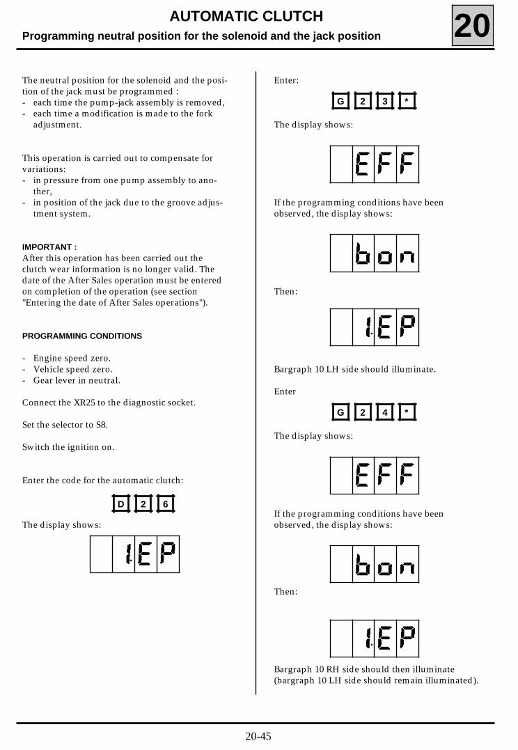
AUTOMATIC CLUTCHProgramming neutral position for the solenoid and the jack position 20The neutral position for the solenoid and the posi-tion of the jack must be programmed :- each time the pump-jack assembly is removed,- each time a modification is made to the fork
adjustment.
This operation is carried out to compensate forvariations:- in pressure from one pump assembly to ano-
ther,- in position of the jack due to the groove adjus-
tment system.
IMPORTANT :After this operation has been carried out theclutch wear information is no longer valid. Thedate of the After Sales operation must be enteredon completion of the operation (see section"Entering the date of After Sales operations").
PROGRAMMING CONDITIONS
- Engine speed zero.- Vehicle speed zero.- Gear lever in neutral.
Connect the XR25 to the diagnostic socket.
Set the selector to S8.
Switch the ignition on.
Enter the code for the automatic clutch:
The display shows:
Enter:
The display shows:
If the programming conditions have beenobserved, the display shows:
Then:
Bargraph 10 LH side should illuminate.
Enter
The display shows:
If the programming conditions have beenobserved, the display shows:
Then:
Bargraph 10 RH side should then illuminate(bargraph 10 LH side should remain illuminated).
D 2 6
G 2 3 *
G 2 4 *
•
•
•
20-45
AUTOMATIC CLUTCH
Programming neutral position for the solenoid and the jack position 20
IMPORTANT :
Switch the ignition off for 10 seconds to validatethe erasing of the values.
When the ignition is switched on again, the valuesare programmed automatically.
The buzzer will sound when the computer hasstored the new values correctly.
Enter the code for the automatic clutch.
Check that the neutral position for the solenoidand the position of the jack have been mem-orised. Bargraphs 10 LH side and 10 RH side shouldbe extinguished.
If bargraph 10 RH side remains illuminated (2 dEFfor *30), check the Part Number of the computer- if the part number is 77 00 102 016 or
77 00 103 880, ignore the illumination of bar-graph 10 RH side,
- if the reference is different, programme theclutch slip point by the following procedure:• warm up the engine until the engine cooling
fan is activated,• switch off the ignition,• disconnect the XR25,• close the bonnet,• sit in the driver’s seat,• close all the doors,• apply the handbrake,• start the engine,• press the brake pedal,• engage 5th gear (do not accelerate),• programming is complete when the buzzer
sounds,• switch off the ignition,• reconnect the XR25.
Erase the computer memory (see section "Faultfinding"). Only bargraphs 1 RH side - 11 RH side -12 LH side - 18 LH side should be illuminated (Forcomputers with Part Numbers 77 00 102 016 or77 00 103 880 bargraph 10 RH side will also be il-luminated).
20-46
AUTOMATIC CLUTCHReading clutch wear 20
The automatic clutch computer allows the level ofclutch wear to be read.
For the reading to be valid, the following condi-tions must be observed:- the original computer must still be fitted,- the pump-jack assembly must not have been
removed since fitting in the factory,- the position of the jack should not have been
programmed since the vehicle left the factory.
Use the XR25 to determine whether these factorsare correct.
Read the date of the last After Sales operation,(see section "Reading the date of After Salesoperations").
If the date read is 00-00-00, the level of wearshown by the XR25 is valid.
TO READ THE WEAR
Connect the XR25 to the diagnostic socket.
Set the selector to S8.
Switch the ignition on.
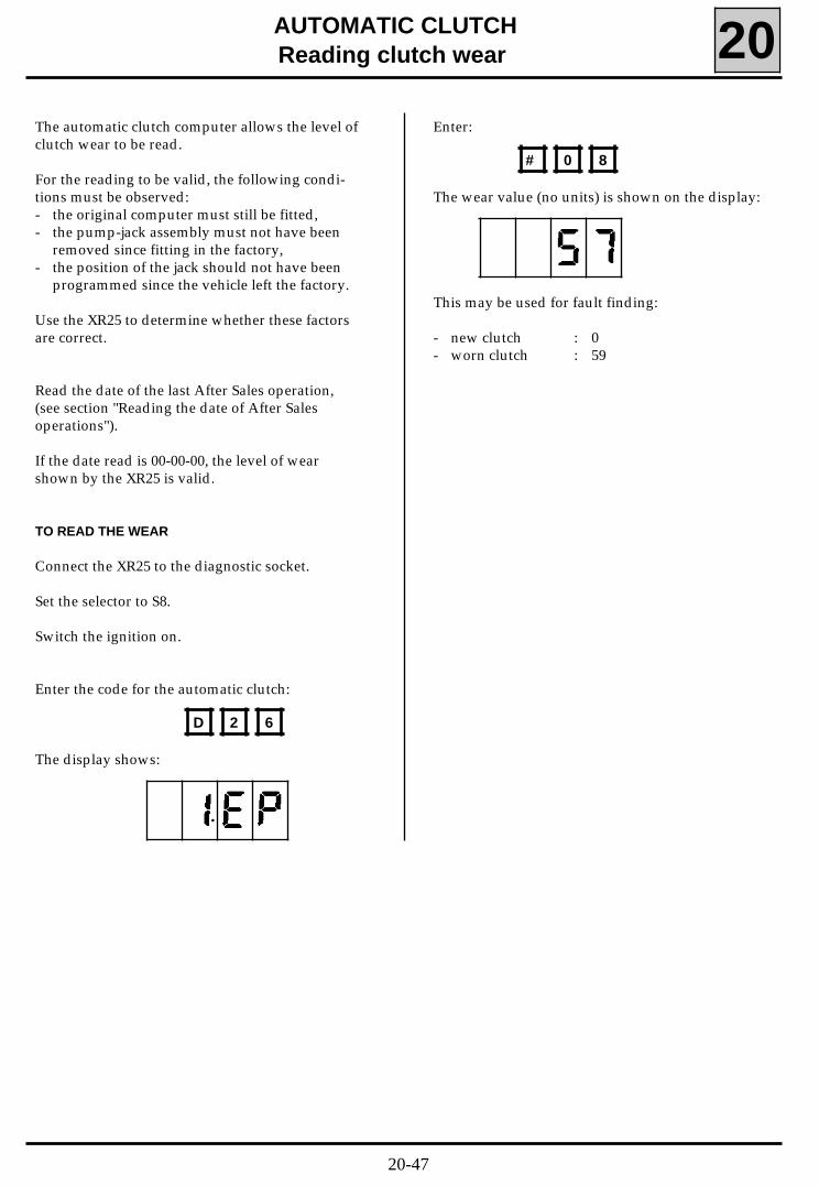
Enter the code for the automatic clutch:
The display shows:
Enter:
The wear value (no units) is shown on the display:
This may be used for fault finding:
- new clutch : 0- worn clutch : 59
D 2 6
# 0 8
•
20-47
It is possible to read the date of the last operationon the automatic clutch, which is stored in thecomputer memory.
To do this:
Connect the XR25 to the diagnostic socket.
Set the selector to S8.
Switch the ignition on.
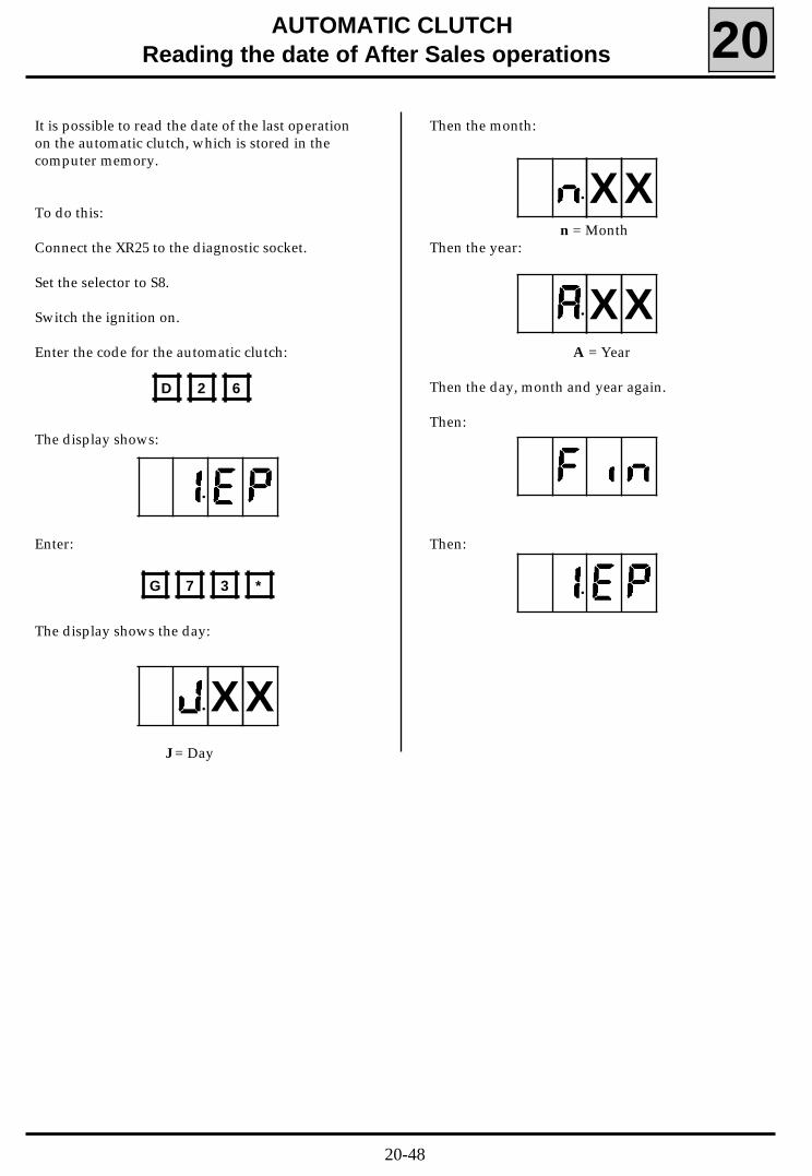
Enter the code for the automatic clutch:
The display shows:
Enter:
The display shows the day:
J = Day
AUTOMATIC CLUTCHReading the date of After Sales operations 20
Then the month:
n = MonthThen the year:
A = Year
Then the day, month and year again.
Then:
Then:
D 2 6
G 7 3 *
•
•
•
•
•
XX
XX
XX
20-48
AUTOMATIC CLUTCH
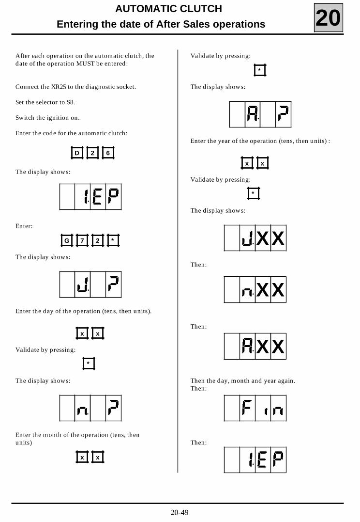
Entering the date of After Sales operations 20After each operation on the automatic clutch, thedate of the operation MUST be entered:
Connect the XR25 to the diagnostic socket.
Set the selector to S8.
Switch the ignition on.
Enter the code for the automatic clutch:
The display shows:
Enter:
The display shows:
Enter the day of the operation (tens, then units).
Validate by pressing:
The display shows:
Enter the month of the operation (tens, thenunits)
Validate by pressing:
The display shows:
Enter the year of the operation (tens, then units) :
Validate by pressing:
The display shows:
Then:
Then:
Then the day, month and year again.Then:
Then:
D 2 6
•
G 7 2 *
x x
*
x x
*
x x
*
•
•
•
•
•
•
•
X
X
X
X
X
X
20-49
AUTOMATIC CLUTCHFault finding 20
GENERAL
The computer has a management system forcontrolling the peripheral components of theautomatic clutch system.
If there is a fault with one of these peripheralcomponents, the computer warns the driver bysounding the buzzer.
At the same time, it sends the automatic clutch in-to defect mode.
The fault which triggered the sounding of thebuzzer may be visualised using the XR25.
Visualised faults are stored in the permanent me-mory and are therefore saved after the ignition isswitched off.
USING BORNIER Elé. 1332
If information obtained using the XR25 requiresverification of electrical continuity, connect bor-nier Elé. 1332 in place of the automatic clutchcomputer to facilitate access to the variouscontact points .
(Bornier Elé 1332 has a solid 25 track base integra-ted with a printed circuit on which are 25 coppercoated contacts, numbered from 1 to 25).
IMPORTANT:• All tests using the Elé. 1332 may only be carried
out after disconnecting the battery.• The bornier is designed to be used only with an
ohmmeter. Under no circumstances should 12Volts be applied to the contact points.
USING THE XR25
The XR25 must be used for fault finding on theautomatic clutch, regardless of the origin of thefaults.
It has a microprocessor which permits:
- all the information from the various sensors tobe read:
- diagnostic messages from the computer to beread,
- various values to be programmed,- the computer permanent memory to be erased.
20-50
AUTOMATIC CLUTCHFault finding 20
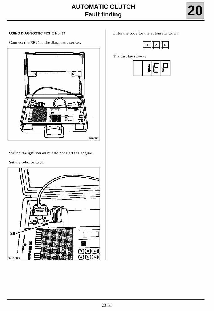
Switch the ignition on but do not start the engine.
Set the selector to S8.
Enter the code for the automatic clutch:
The display shows:
D 2 6
•
USING DIAGNOSTIC FICHE No. 29
Connect the XR25 to the diagnostic socket.
92656S
92655R3
20-51
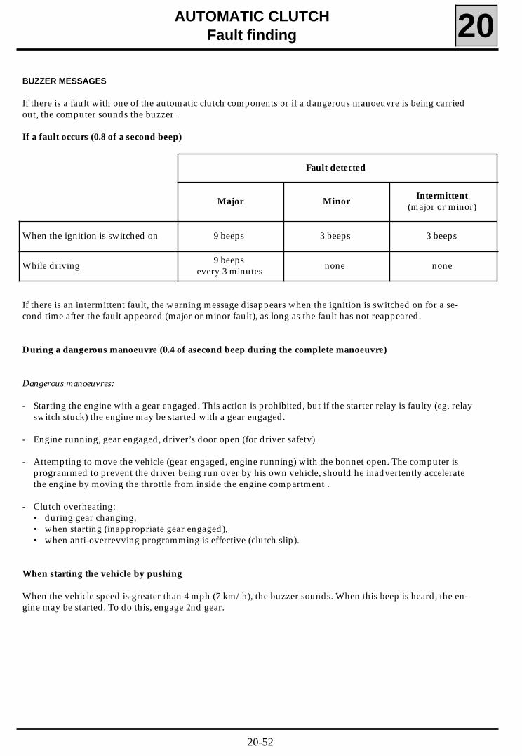
Fault detected
Major MinorIntermittent
(major or minor)
When the ignition is switched on 9 beeps 3 beeps 3 beeps
While driving 9 beepsevery 3 minutes none none
AUTOMATIC CLUTCHFault finding 20
BUZZER MESSAGES
If there is a fault with one of the automatic clutch components or if a dangerous manoeuvre is being carriedout, the computer sounds the buzzer.
If a fault occurs (0.8 of a second beep)
If there is an intermittent fault, the warning message disappears when the ignition is switched on for a se-cond time after the fault appeared (major or minor fault), as long as the fault has not reappeared.
During a dangerous manoeuvre (0.4 of asecond beep during the complete manoeuvre)
Dangerous manoeuvres:
- Starting the engine with a gear engaged. This action is prohibited, but if the starter relay is faulty (eg. relayswitch stuck) the engine may be started with a gear engaged.
- Engine running, gear engaged, driver’s door open (for driver safety)
- Attempting to move the vehicle (gear engaged, engine running) with the bonnet open. The computer isprogrammed to prevent the driver being run over by his own vehicle, should he inadvertently acceleratethe engine by moving the throttle from inside the engine compartment .
- Clutch overheating:• during gear changing,• when starting (inappropriate gear engaged),• when anti-overrevving programming is effective (clutch slip).
When starting the vehicle by pushing
When the vehicle speed is greater than 4 mph (7 km/h), the buzzer sounds. When this beep is heard, the en-gine may be started. To do this, engage 2nd gear.
20-52
AUTOMATIC CLUTCHFault finding 20
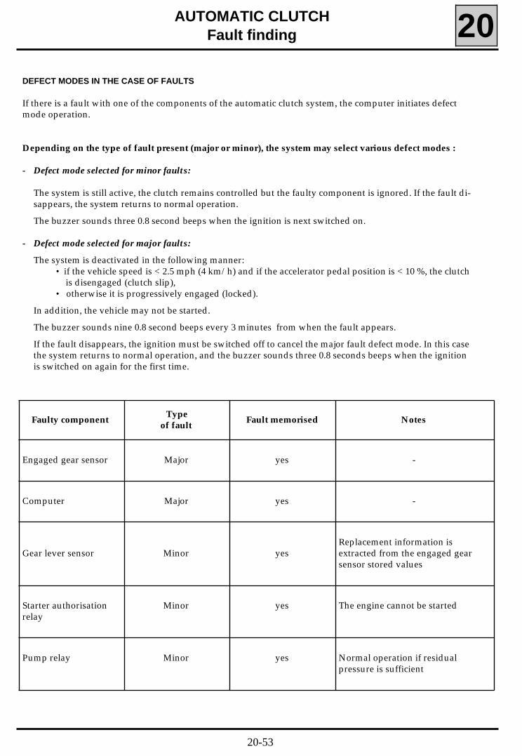
Faulty componentType
of faultFault memorised Notes
Engaged gear sensor Major yes -
Computer Major yes -
Gear lever sensor Minor yesReplacement information isextracted from the engaged gearsensor stored values
Starter authorisationrelay
Minor yes The engine cannot be started
Pump relay Minor yes Normal operation if residualpressure is sufficient
DEFECT MODES IN THE CASE OF FAULTS
If there is a fault with one of the components of the automatic clutch system, the computer initiates defectmode operation.
Depending on the type of fault present (major or minor), the system may select various defect modes :
- Defect mode selected for minor faults:
The system is still active, the clutch remains controlled but the faulty component is ignored. If the fault di-sappears, the system returns to normal operation.
The buzzer sounds three 0.8 second beeps when the ignition is next switched on.
- Defect mode selected for major faults:
The system is deactivated in the following manner:• if the vehicle speed is < 2.5 mph (4 km/h) and if the accelerator pedal position is < 10 %, the clutch
is disengaged (clutch slip),• otherwise it is progressively engaged (locked).
In addition, the vehicle may not be started.
The buzzer sounds nine 0.8 second beeps every 3 minutes from when the fault appears.
If the fault disappears, the ignition must be switched off to cancel the major fault defect mode. In this casethe system returns to normal operation, and the buzzer sounds three 0.8 seconds beeps when the ignitionis switched on again for the first time.
20-53
AUTOMATIC CLUTCHFault finding 20
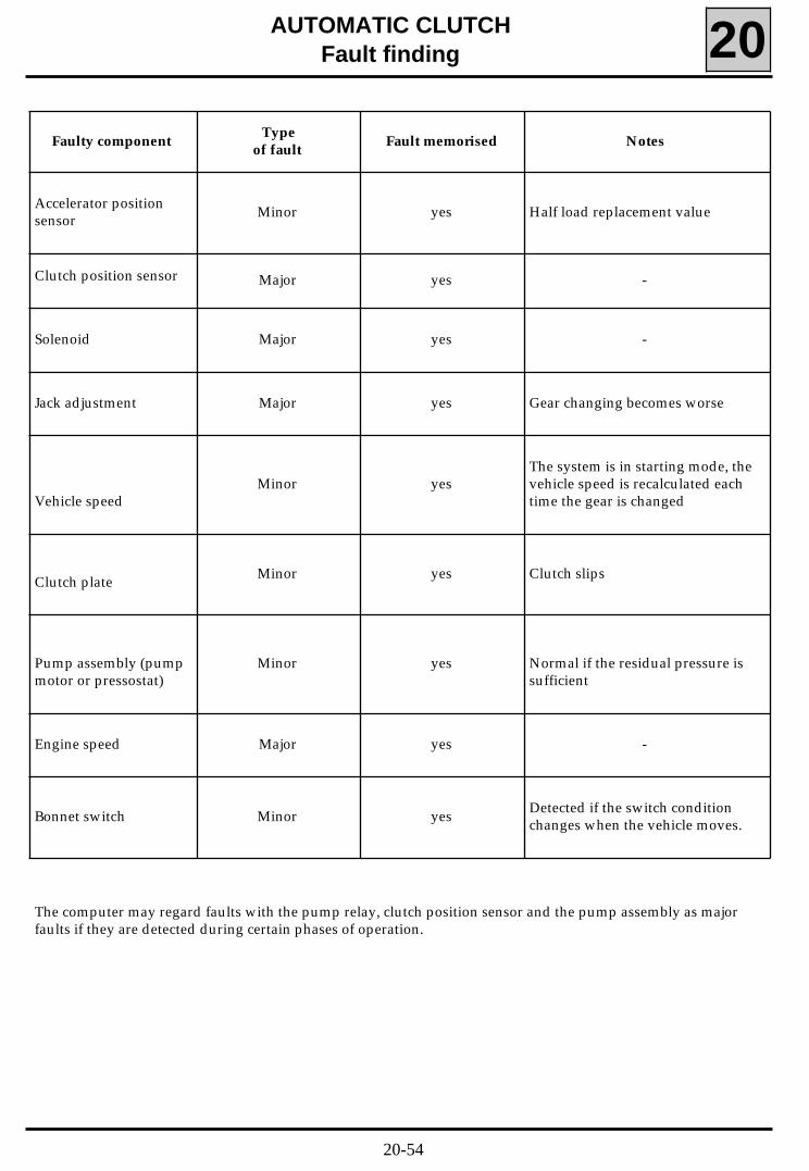
Faulty componentType
of faultFault memorised Notes
Accelerator positionsensor Minor yes Half load replacement value
Clutch position sensor Major yes -
Solenoid Major yes -
Jack adjustment Major yes Gear changing becomes worse
Vehicle speedMinor yes
The system is in starting mode, thevehicle speed is recalculated eachtime the gear is changed
Clutch plate Minor yes Clutch slips
Pump assembly (pumpmotor or pressostat)
Minor yes Normal if the residual pressure issufficient
Engine speed Major yes -
Bonnet switch Minor yes Detected if the switch conditionchanges when the vehicle moves.
The computer may regard faults with the pump relay, clutch position sensor and the pump assembly as majorfaults if they are detected during certain phases of operation.
20-54
AUTOMATIC CLUTCHFault finding - introduction 20TWINGO
APPLICATION CONDITIONS FOR CHECKS DEFINED IN THIS FAULT FINDING
The tests described in this fault finding section are only to be applied if the description of the faultcorresponds exactly to the display on the XR25.If a fault is dealt with as a result of a flashing bargraph, the conditions confirming the actual presence of afault (and the necessity for applying fault finding) appear in the "NOTES" box, or at the beginning of thebargraph interpretation.
If a bargraph is only interpreted when it is permanently illuminated, the application of the testsrecommended in the fault finding section for the flashing bargraph will not determine the cause of thememorised fault. In this case, only the wiring and connections for the faulty component should be checked.
NOTE: The ignition should be switched off before the XR25 is used.
SPECIAL TOOLING REQUIRED FOR OPERATIONS ON THE AUTOMATIC CLUTCH SYSTEM
- XR25
- XR25 cassette no. 15 minimum
- 25 track test bornier Elé. 1332.
Special Note:After replacing the computer, programme full-load and no-load values and gear lever positions. Neutralposition for the solenoid and the jack position are programmed automatically when the ignition is switchedon.
2EMBP1.0
20-55
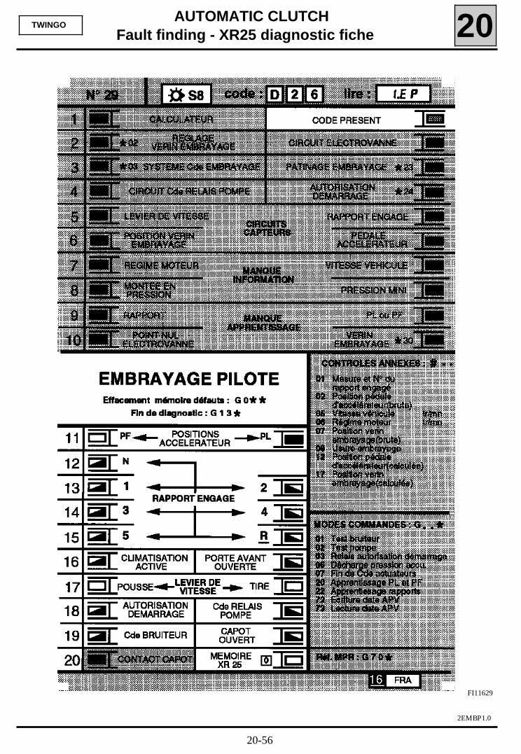
AUTOMATIC CLUTCHFault finding - XR25 diagnostic fiche 20TWINGO
FI11629
2EMBP1.0
20-56
AUTOMATIC CLUTCHFault finding - XR25 diagnostic fiche 20
2EMBP1.0
TWINGO
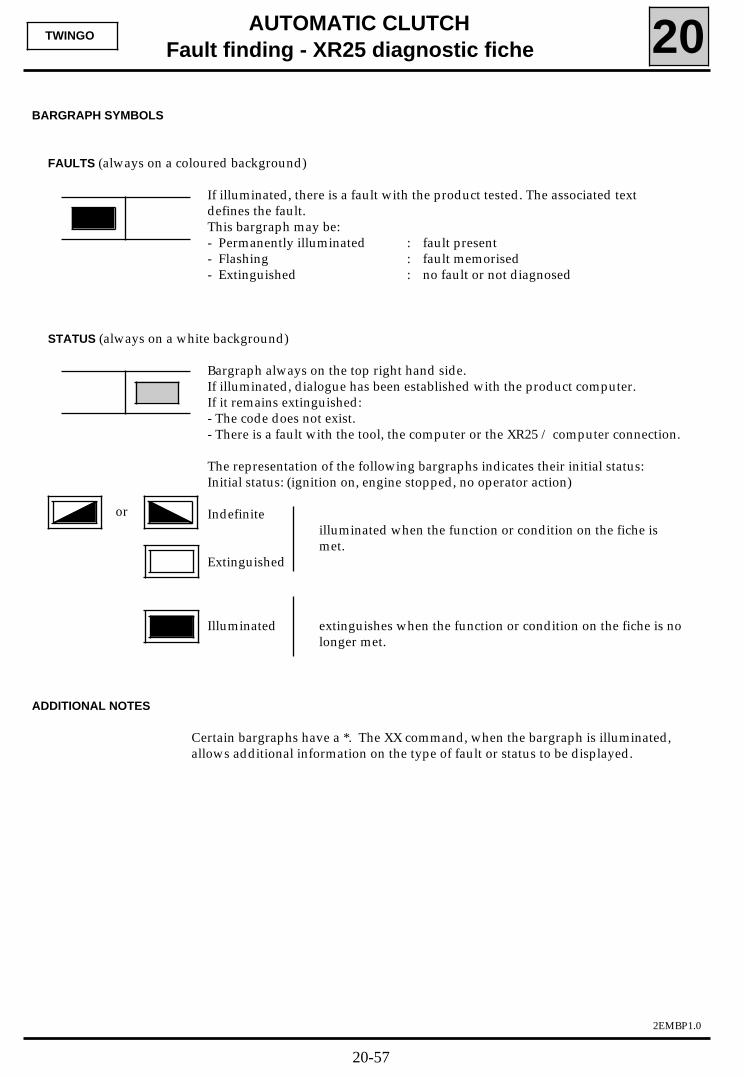
BARGRAPH SYMBOLS
FAULTS (always on a coloured background)
If illuminated, there is a fault with the product tested. The associated textdefines the fault.This bargraph may be:- Permanently illuminated : fault present- Flashing : fault memorised- Extinguished : no fault or not diagnosed
STATUS (always on a white background)
Bargraph always on the top right hand side.If illuminated, dialogue has been established with the product computer.If it remains extinguished:- The code does not exist.- There is a fault with the tool, the computer or the XR25 / computer connection.
The representation of the following bargraphs indicates their initial status:Initial status: (ignition on, engine stopped, no operator action)
Indefiniteilluminated when the function or condition on the fiche ismet.
Extinguished
Illuminated extinguishes when the function or condition on the fiche is nolonger met.
ADDITIONAL NOTES
Certain bargraphs have a *. The XX command, when the bargraph is illuminated,allows additional information on the type of fault or status to be displayed.
or
20-57
AUTOMATIC CLUTCH
Fault finding - Interpretation of XR25 bargraphs 20
2EMBP1.0
TWINGO
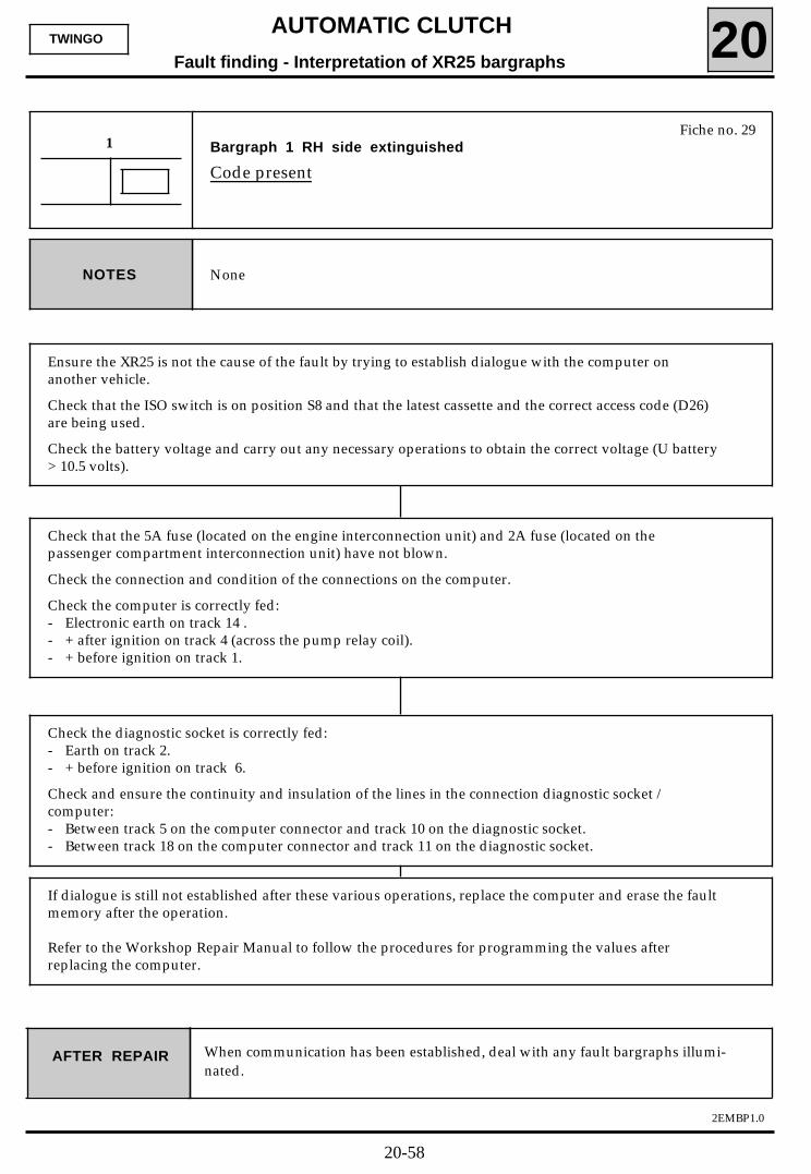
Fiche no. 29Bargraph 1 RH side extinguished
Code present
1
NoneNOTES
Ensure the XR25 is not the cause of the fault by trying to establish dialogue with the computer onanother vehicle.
Check that the ISO switch is on position S8 and that the latest cassette and the correct access code (D26)are being used.
Check the battery voltage and carry out any necessary operations to obtain the correct voltage (U battery> 10.5 volts).
When communication has been established, deal with any fault bargraphs illumi-nated.
Check that the 5A fuse (located on the engine interconnection unit) and 2A fuse (located on thepassenger compartment interconnection unit) have not blown.
Check the connection and condition of the connections on the computer.
Check the computer is correctly fed:- Electronic earth on track 14 .- + after ignition on track 4 (across the pump relay coil).- + before ignition on track 1.
Check the diagnostic socket is correctly fed:- Earth on track 2.- + before ignition on track 6.
Check and ensure the continuity and insulation of the lines in the connection diagnostic socket /computer:- Between track 5 on the computer connector and track 10 on the diagnostic socket.- Between track 18 on the computer connector and track 11 on the diagnostic socket.
If dialogue is still not established after these various operations, replace the computer and erase the faultmemory after the operation.
Refer to the Workshop Repair Manual to follow the procedures for programming the values afterreplacing the computer.
AFTER REPAIR
20-58

AUTOMATIC CLUTCH
Fault finding - Interpretation of XR25 bargraphs 20
2EMBP1.0
TWINGO
Fiche no. 29Bargraph 1 LH side illuminated
Computer fault
1
NoneNOTES
Replace the automatic clutch computer, then erase the memory of the new computer (G0**).
Refer to the Workshop Repair Manual to follow the procedures for programming the values afterreplacing the computer.
AFTER REPAIR After replacing the computer, carry out another test with the XR25.
20-59
AUTOMATIC CLUTCHFault finding - Interpretation of XR25 bargraphs 20
2EMBP1.0
TWINGO
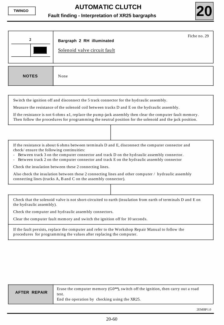
Fiche no. 29Bargraph 2 RH illuminated
Solenoid valve circuit fault
2
NoneNOTES
Switch the ignition off and disconnect the 5 track connector for the hydraulic assembly.
Measure the resistance of the solenoid coil between tracks D and E on the hydraulic assembly.
If the resistance is not 6 ohms ±1, replace the pump-jack assembly then clear the computer fault memory.Then follow the procedures for programming the neutral position for the solenoid and the jack position.
AFTER REPAIRErase the computer memory (G0**), switch off the ignition, then carry out a roadtest.End the operation by checking using the XR25.
If the resistance is about 6 ohms between terminals D and E, disconnect the computer connector andcheck/ensure the following continuities:- Between track 3 on the computer connector and track D on the hydraulic assembly connector.- Between track 2 on the computer connector and track E on the hydraulic assembly connector
Check the insulation between these 2 connecting lines.
Also check the insulation between these 2 connecting lines and other computer / hydraulic assemblyconnecting lines (tracks A, B and C on the assembly connector).
Check that the solenoid valve is not short-circuited to earth (insulation from earth of terminals D and E onthe hydraulic assembly).
Check the computer and hydraulic assembly connectors.
Clear the computer fault memory and switch the ignition off for 10 seconds.
If the fault persists, replace the computer and refer to the Workshop Repair Manual to follow theprocedures for programming the values after replacing the computer.
20-60
AUTOMATIC CLUTCH
Fault finding - Interpretation of XR25 bargraphs 20
2EMBP1.0
TWINGO
2
NOTES
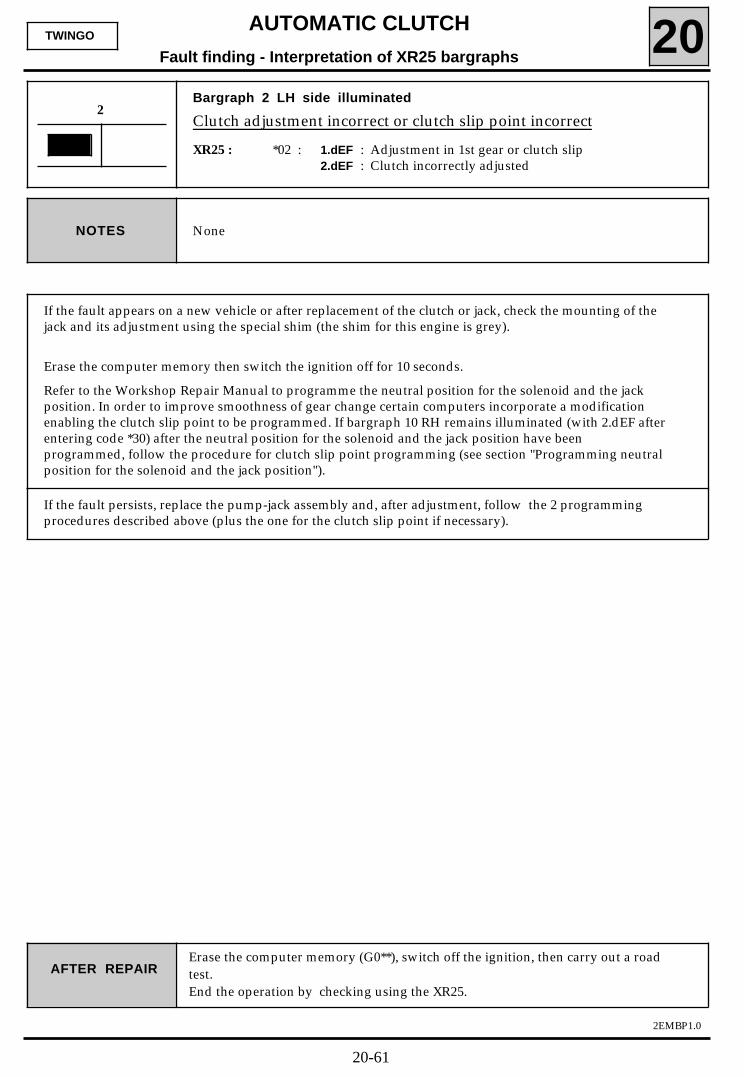
If the fault appears on a new vehicle or after replacement of the clutch or jack, check the mounting of thejack and its adjustment using the special shim (the shim for this engine is grey).
Erase the computer memory then switch the ignition off for 10 seconds.
Refer to the Workshop Repair Manual to programme the neutral position for the solenoid and the jackposition. In order to improve smoothness of gear change certain computers incorporate a modificationenabling the clutch slip point to be programmed. If bargraph 10 RH remains illuminated (with 2.dEF afterentering code *30) after the neutral position for the solenoid and the jack position have beenprogrammed, follow the procedure for clutch slip point programming (see section "Programming neutralposition for the solenoid and the jack position").
AFTER REPAIRErase the computer memory (G0**), switch off the ignition, then carry out a roadtest.End the operation by checking using the XR25.
If the fault persists, replace the pump-jack assembly and, after adjustment, follow the 2 programmingprocedures described above (plus the one for the clutch slip point if necessary).
Bargraph 2 LH side illuminated
Clutch adjustment incorrect or clutch slip point incorrect
XR25 : *02 : 1.dEF : Adjustment in 1st gear or clutch slip2.dEF : Clutch incorrectly adjusted
None
20-61
AUTOMATIC CLUTCH
Fault finding - Interpretation of XR25 bargraphs 20
2EMBP1.0
TWINGO
Bargraph 3 RH side flashing
Clutch slip fault
XR25 : *23 : 1.dEF : Comparison of engine and vehicle speeds2.dEF : Clutch slip
3
AFTER REPAIRErase the computer memory (G0**), switch off the ignition, then carry out a roadtest.End the operation by checking using the XR25.
1.dEF
Check the computer is correct for the vehicle type (special computer if the vehicle has air conditioning).Check the gearbox is correct for the vehicle type (special gearbox if the vehicle has air conditioning).
Check the vehicle speed / engine speed information lines:- Ensure continuity and insulation of the line between track B1 on the vehicle speed sensor and track 23
on the computer connector.- Ensure continuity and insulation of the line between track 48 on the injection computer connector and
track 11 on the automatic clutch computer connector.
If one of bargraphs 5 RH side, 7 RH side or 7 LH side is also illuminated, treat thatbargraph before 3 RH side. Even if it is present at the moment of testing, this fault isalways shown by bargraph 3 RH side flashing. To confirm the fault is present, andtherefore the necessity of applying the fault finding below, erase the computermemory, switch off the ignition and carry out a road test.The fault is present if the bargraph reappears flashing.
NOTES
Fiche no. 29
NoneNOTES
Check the operation of the engaged gear sensor (mechanical fault in the sensor):- Use function #01 on the XR 25, move the gear lever through all the gear positions and monitor the dis-
play on the XR25.• If, when a new gear is engaged, the XR25 still shows the display for the previous gear for a certain
time, replace the engaged gear sensor and follow the procedure for programming the gears.• If when a new gear is engaged the XR25 shows a value followed by ".=" (130.=), check the gear-
box control, the fitting and tightness of the engaged gear sensor.
Use bargraphs 17 LH and RH sides to check the consistency of the push / pull information (switches in thegear lever knob incorrectly wired).
20-62
AUTOMATIC CLUTCH
Fault finding - Interpretation of XR25 bargraphs 20
2EMBP1.0
TWINGO
AFTER REPAIRErase the computer memory (G0**), switch off the ignition, then carry out a roadtest.End the operation by checking using the XR25.
Continued
2.dEF
Check there is no oil on the clutch plate.
Read the clutch wear value for #08.
NOTE: This value is not representative of actual clutch wear if the jack position has been programmed wi-thout the clutch being replaced (wear value is reset to zero). The theoretical wear value for acompletely worn clutch is 59.
- Replace the clutch if the wear value is close to 59 and follow the procedure for programming the neu-tral position for the solenoid and the jack position (refer to this Workshop Repair Manual).
- If the wear value is relatively below 59, a measurement must be made of the actual clutch wear toconfirm the reading. This measurement is made between the pressure surface of the jack on the gearbox housing and the end of the cable end section, when the clutch is engaged (ignition off).
The dimension is 123 mm when the clutch is new if the jack is correctly fitted and adjusted with a specialshim.
Replace the clutch if the dimension is approximately 140 mm (without modifying the adjustment) and fol-low the procedure for programming the neutral position for the solenoid and the jack position (refer tothe Workshop Repair Manual).
NoneNOTES
3
20-63
AUTOMATIC CLUTCHFault finding - Interpretation of XR25 bargraphs 20
2EMBP1.0
TWINGO
Bargraph 3 LH side illuminated or flashing
Clutch control fault
XR25 : *03 : 1.dEF : Solenoid seizing or nozzle blocked2.dEF : Clutch control fault
3
NoneNOTES
AFTER REPAIRErase the computer memory (G0**), switch off the ignition, then carry out a roadtest.End the operation by checking using the XR25.
Fiche no. 29
1.dEF NOTES
Check the clutch cable is not broken or unclipped.
Switch off the ignition and disconnect the 5 track hydraulic assembly connector. Measure the resistanceof the solenoid coil between tracks D and E on the hydraulic assembly.
Replace the hydraulic assembly if the resistance is not 6 ohms ± 1.
Disconnect the computer connector and check / ensure insulation between the following 2 lines:- Between track 3 on the computer connector and track D on the hydraulic assembly connector.- Between track 2 on the computer connector and track E on the hydraulic assembly connector
Check / ensure the insulation between these 2 lines and other computer / hydraulic assembly connectinglines (tracks A, B and C on the assembly connector).
Also check the insulation from earth of terminals D and E on the hydraulic assembly.
Check / ensure continuity between earth and track C on the hydraulic assembly connector and betweentrack B on the assembly connector and track 24 on the computer connector.
Check the connections on the hydraulic assembly and on the computer. If the connections, continuitiesand insulation are correct, erase the computer memory then switch the ignition off for 10 seconds.
Replace the hydraulic assembly / clutch jack if the fault reappears (solenoid or jack seized, pressostatfaulty,..) and follow the procedure for programming the solenoid neutral position and the jack position.(refer to the Workshop Repair Manual).
Treat bargraph 6 LH side first if it is also illuminated.
20-64
AUTOMATIC CLUTCHFault finding - Interpretation of XR25 bargraphs 20
2EMBP1.0
TWINGO
AFTER REPAIRErase the computer memory (G0**), switch off the ignition, then carry out a roadtest.End the operation by checking using the XR25.
Continued
2.dEF
Check the clutch cable is not broken or unclipped.
Look for a short circuit in the solenoid or the solenoid wiring:
- Measure the resistance of the solenoid coil between tracks D and E of the assembly and replace theassembly if the resistance is not approximately 6 ohms ± 1.
- Ensure the insulation between the 2 lines on the solenoid and the insulation of these 2 lines from othercomputer / hydraulic assembly connecting lines.
- Ensure the insulation from earth of terminals D and E on the hydraulic assembly.
Check / ensure continuity between earth and track C on the hydraulic assembly connector and betweentrack B on the assembly connector and track 24 on the computer connector.
Treat any other illuminated bargraph first.NOTES
Check the connections on the hydraulic assembly and on the computer. If the connections, continuitiesand insulation are correct, erase the computer memory then switch the ignition off for 10 seconds.
Replace the hydraulic assembly / clutch jack if the fault reappears (solenoid or jack seized, pressostatfaulty,...) and follow the procedure for programming the solenoid neutral position and the jack position(refer to the Workshop Repair Manual).
3
20-65
AUTOMATIC CLUTCHFault finding - Interpretation of XR25 bargraphs 20
2EMBP1.0
TWINGO
Bargraph 4 RH side illuminated (1.dEF)or flashing (2.dEF)
Starter authorisation faultXR25 : *24 : 1.dEF : Starter relay fault
2.dEF : Starter circuit fault, starting fault outside of authorisation conditions
4
The starter relay is located on the passenger compartment panel.NOTES
AFTER REPAIRErase the computer memory (G0**), switch off the ignition, then carry out a roadtest.End the operation by checking using the XR25.
Fiche no. 29
1.dEF NoneNOTES
Check the resistance of the starter relay coil (between pins 1 and 2)
If the resistance is not 65 ohms ± 10% replace the starter relay.
Check/ensure continuity and insulation (CC.0 and CC.1) of the line between track 16 on the computerconnector and terminal 2 on the base of the relay.
Ensure there is +after ignition feed present at terminal 1 of the relay base.
If the continuity and insulation are correct, erase the computer memory and switch the ignition off for 10seconds. Replace the computer if the fault reappears and refer to the Workshop Repair Manual to followthe procedures for programming values after replacing the computer.
2.dEF NoneNOTES
Try to start the engine with a gear engaged.
If the engine does not start, ignore this fault information
Erase the computer memory.
If the engine starts, remove the starter relay and measure the voltage at terminal 5 on the relay basewhen the starter is activated.- If the voltage is zero, replace the starter relay (switch is stuck).- If there is 12 volts, ensure the insulation from 12 volts of the line between this terminal 5 and the
starter.
After the operation, erase the computer memory then switch the ignition off for 10 seconds.
20-66
AUTOMATIC CLUTCHFault finding- Interpretation of XR25 bargraphs 20
2EMBP1.0
TWINGO
Fiche no. 29Bargraph 4 LH side illuminated
Pump relay control circuit fault
4
AFTER REPAIRErase the computer memory (G0**), switch off the ignition, then carry out a roadtest.End the operation by checking using the XR25.
If bargraph 4 LH side is permanently illuminated after switching the ignition off and using the XR25, theonly fault which may be present on the vehicle is a permanent + after ignition feed fault on track 4 ofthe computer connector (short circuit relay coil, ...).
An open circuit or short circuit fault to earth on the line will not be detected by the XR25 as a check putsthe computer out of service if there is not + after ignition feed on track 4 when the ignition is switchedon.
The electro-pump assembly relay is located on the engine board.NOTES
- Replace the pump motor relay.- Ensure insulation of the line between track 4 of the computer connector and terminal 2 of the pump
motor relay base.
After the operation, erase the computer memory then switch the ignition off for 10 seconds.
Replace the computer if the fault reappears and refer to the Workshop Repair Manual for application ofthe procedures for programming the values after replacing the computer.
20-67
AUTOMATIC CLUTCHFault finding- Interpretation of XR25 bargraphs 20
2EMBP1.0
TWINGO
Fiche no. 29Bargraph 5 RH side illuminated
Engaged gear potentiometer circuit fault
5
NoneNOTES
Is bargraph 6 LH side also illuminated?
AFTER REPAIRErase the computer memory (G0**), switch off the ignition, then carry out a roadtest.End the operation by checking using the XR25.
YES The fault is caused by a short circuit on one of the 2 potentiometers, a fault on the poten-tiometer 5 volt feed line (track 20 on the computer) or on their earth (track 7 on the compu-ter).
- Switch the ignition off and check the 2 potentiometers.Replace the potentiometer with a short circuit between tracks A and C.
- Check and ensure continuity and insulation of the following lines:• Between track 20 on the computer connector and tracks A on the engaged gear po-
tentiometer connector and C on the jack position potentiometer connector.• Between track 7 on the computer connector and tracks C of the gear engaged poten-
tiometer connector and A on the jack position potentiometer connector.
- Also check / ensure insulation between tracks 7 and 20 on the computer connector.
After the operation, erase the computer memory then switch the ignition off for 10 seconds.
Replace the computer if the fault reappears and follow the procedures for programming the values afterreplacing the computer.
20-68
AUTOMATIC CLUTCHFault finding- Interpretation of XR25 bargraphs 20
2EMBP1.0
TWINGO
AFTER REPAIRErase the computer memory (G0**), switch off the ignition, then carry out a roadtest.End the operation by checking using the XR25.
Continued
NO
After the operation, erase the computer memory then switch the ignition off for 10 seconds.
Replace the computer if the fault reappears and follow the procedures for programming the values afterreplacing the computer.
Use function #01 on the XR25 with the gear lever in neutral.
If the value for #01 is consistent (between 113 and 142), move the lever to see if the valuechanges to a value in the range for a sensor fault (value < 5 or > 250).
In this case check the gearbox control, the mounting and tightening of the sensor.
Replace the engaged gear sensor if necessary.
Erase the computer memory, switch the ignition off for 10 seconds then follow theprocedure for programming the gears.
If the value for #01 equals 0.=, 255.= or 255.r, carry out the following tests:
- Check the condition of the engaged gear sensor connector and the quality of itsconnections.
- Ensure the continuity and insulation of the following lines:• Between track 20 on the computer connector and track A on the sensor connector.• Between track 9 on the computer connector and track B on the sensor connector.
- Ensure continuity between track 7 on the computer connector and track C on the sensorconnector
- Also ensure insulation between the sensor lines.
- Ensure insulation from earth of the line between track 20 on the computer connectorand track C on the clutch jack position potentiometer connector.
- Replace the engaged gear sensor, erase the computer memory, then follow theprocedure for programming the gears (before draining the gear box to make thereplacement, use function #01 to test the correct operation of the system by connectingthe new sensor in place of the old one and actuating the follower).
5
20-69
AUTOMATIC CLUTCHFault finding- Interpretation of XR25 bargraphs 20
2EMBP1.0
TWINGO
Fiche no. 29Bargraph 5 LH side illuminated or flashing
Gear lever sensor circuit fault
5
NoneNOTES
BARGRAPH 5 LH SIDE PERMANENTLY ILLUMINATED
AFTER REPAIRErase the computer memory (G0**), switch off the ignition, then carry out a roadtest.End the operation by checking using the XR25.
If bargraph 5 LH side is permanently illuminated after the ignition has been switched off and the XR25 setup, there is a permanent earth on tracks 12 and 13 on the computer (CC.0 on the 2 lines for the push andpull switches, which corresponds to the lever being in a pushed and pulled condition at the same time). Inthis case bargraphs 17 LH and RH sides are extinguished as the fault is present.
Disconnect the 3 track connector located at the bottom of the gear lever and check the condition of theswitches in the knob without touching the lever.
- If there is continuity between tracks C and A and between tracks C and B, replace the lever
- If the lever is not faulty, ensure insulation from earth for the following lines:• Between track 12 on the computer connector and track B on the 3 track lever connector.• Between track 13 on the computer connector and track A on the 3 track lever connector.
BARGRAPH 5 LH SIDE FLASHING
In this case, bargraphs 17 LH and RH sides are operational as the lever is not in a pushed and pulledcondition at the same time.
Is either bargraph 17 LH or RH side illuminated with no action on the lever ?
- If bargraph 17 RH side is permanently illuminated : "Pull" switch is faulty or short circuit to earth onthe line between track 12 on the computer connector and track B on the 3 track lever connector.Replace the lever if there is continuity between tracks C and B on the lever connector or repair thewiring.
- If bargraph 17 LH side is permanently illuminated : "Push" switch is faulty or short circuit to earth onthe line between track 13 on the computer connector and track A on the 3 track lever connector.Replace the lever if there is continuity between tracks C and A on the lever connector or repair thewiring.
- If neither side of bargraph 17 is illuminated: move the lever and check to see if there is alternateright / left illumination.If one side of bargraph 17 is illuminated without action on the lever, carry out the checks specifiedabove for the appropriate bargraph illuminated.
20-70
AUTOMATIC CLUTCHFault finding- Interpretation of XR25 bargraphs 20
2EMBP1.0
TWINGO
Fiche no. 29Bargraph 6 RH side illuminated
Accelerator pedal sensor circuit fault (load information via injection)
6
None.NOTES
AFTER REPAIRErase the computer memory (G0**), switch off the ignition, then carry out a roadtest.End the operation by checking using the XR25.
Ensure continuity and insulation of the connection between track 10 of the automatic clutch computerconnector and track 41 of the injection computer connector.
Check the connections of the 2 computers.
Erase the computer memory then switch the ignition off for 10 seconds.
If the fault persists, replace the computer and refer to the Workshop Repair Manual and follow theprocedures for programming the values after replacing the computer.
20-71
AUTOMATIC CLUTCHFault finding- Interpretation of XR25 bargraphs 20
2EMBP1.0
TWINGO
Fiche no. 29Bargraph 6 LH side illuminated
Clutch jack position sensor circuit fault
6
Refer to the fault finding for bargraph 5 RH side if it is also illuminated.NOTES
AFTER REPAIRErase the computer memory (G0**), switch off the ignition, then carry out a roadtest.End the operation by checking using the XR25.
Use the function #07 on the XR 25, clutch engaged (lever in neutral+ accelerator pedal not depressed).
If the value for #07 is consistent (between 20 and 155 clutch out) :- Press the accelerator pedal down completely to let the clutch disengage fully.
- Replace the jack if the value for #07 is in the range for a potentiometer fault (value is > 250).
Erase the computer memory, then switch the ignition off for 10 seconds.
Refer to the Workshop Repair Manual and follow the procedure for programming the neutral positionfor the solenoid and the jack position.If the value for #07 is incorrect or is equal to 0 or 255 :- Check the jack position potentiometer connector and the quality of its connections.- Ensure continuity and insulation of the line between track 22 on the computer connector and track B
on the jack position potentiometer connector.- Ensure continuity and insulation from earth of the line between track 20 on the computer connector
and track C on the jack position potentiometer connector.- Ensure continuity between track 7 on the computer connector and track A on the jack position
potentiometer connector.
Also ensure insulation between the potentiometer lines.
If all these tests are correct, erase the computer memory, switch the ignition off for 10 seconds thenfollow the procedure for programming the neutral position for the solenoid and the jack position.
If the fault reappears, replace the clutch control jack and follow the procedure for programming theneutral position for the solenoid and the jack position.
Replace the computer if the fault reappears and follow the procedures for programming the values afterreplacing the computer.
20-72
AUTOMATIC CLUTCHFault finding- Interpretation of XR25 bargraphs 20
2EMBP1.0
TWINGO
Fiche no. 29Bargraph 7 RH side flashing
Vehicle speed information fault
7
If bargraph 5 RH side is also illuminated, treat that bargraph before bargraph 7 RHside.NOTES
AFTER REPAIRErase the computer memory (G0**), switch off the ignition, then carry out a roadtest.End the operation by checking using the XR25.
Even if this fault is present on the vehicle during the test, it may only be signalled by a flashing bargraphon the XR25 (under the conditions specified at the start of this fault finding section) as it is taken intoaccount by the computer only when the vehicle is moving.
A road test must be carried out to determine the origin of the fault.
For information, the vehicle speed for #05 is 10 times the value shown on the instrument panel (50 km/h- -> 500 wheel revolutions per minute for #05).
If, during a road test, the vehicle speed information on the instrument panel is not consistent or is zero,carry out a complete test of the vehicle speed sensor :- Check the connections on the sensor connector.- + after ignition on track A1 of the sensor connector.- Earth on track C1 of the sensor connector.
Replace the sensor if necessary.
If, during the road test, the vehicle speed information for #05 is zero but this is consistent with theinstrument panel, the following tests should be carried out:- Check / ensure continuity and insulation of the line between track 23 on the computer connector and
track B1 of the vehicle speed sensor connector.- Also check the condition of the connections along the whole length of the line.
20-73

AUTOMATIC CLUTCHFault finding- Interpretation of XR25 bargraphs 20
2EMBP1.0
TWINGO
Fiche no. 29Bargraph 7 LH side flashing
Engine speed information fault
7
NoneNOTES
The engine speed signal is sent by the injection computer on the fuel pump relay control line. Even if thisfault is present on the vehicle during the test, it may only be signalled by a flashing bargraph on the XR25(under the conditions specified at the start of this fault finding section ) as it is taken into account by thecomputer only when the vehicle is moving.
AFTER REPAIRErase the computer memory (G0**), switch off the ignition, then carry out a roadtest.End the operation by checking using the XR25.
After the operation, erase the computer memory then switch the ignition off for 10 seconds.
Replace the computer if the fault reappears and follow the procedures for programming the values afterreplacing the computer
If the engine does not start there is a short circuit to earth on this line.
If the vehicle starts but is immobilised as the clutch jack is not engaged, the computer is not receiving TDCinformation.
In both of these cases the following checks should be made:- Check / ensure continuity and insulation from earth of the line between track 11 on the automatic
clutch computer connector and terminal 2 on the fuel pump relay base.- Also check the condition of the connections along the whole length of the line.- Check / ensure continuity and insulation from earth of the line between terminal 2 of the fuel pump
relay base and track 48 of the injection computer connector.
20-74
AUTOMATIC CLUTCHFault finding- Interpretation of XR25 bargraphs 20
2EMBP1.0
TWINGO
Fiche no. 29Bargraph 8 RH side illuminated continuously or flashing
MInimum pressure information fault
8
If bargraph 2 LH side is also illuminated, treat that bargraph before bargraph 8 RHside.NOTES
This fault may occur after using the command mode for discharging the pressure in the hydraulicassembly. In this case, just erase the computer memory.
AFTER REPAIRErase the computer memory (G0**), switch off the ignition, then carry out a roadtest.End the operation by checking using the XR25.
If the command mode has not been used:- Replace the pump motor relay if the pump motor is running continuously (in this case the motor runs
very noisily due to the action of the pressure release valve).- Check the condition of the connections at the relay base (sealing, ...).- Check / ensure continuity between earth and track C on the hydraulic assembly connector and
between track B on the assembly connector and track 24 on the computer connector.- Check the connections on the hydraulic assembly and the computer.
If the connections and continuity are good, wait for 5 minutes with the ignition off while the pressuredrops in the hydraulic assembly then check the continuity between tracks B and C on the assemblyconnector, on the assembly side.- If there is no continuity between the two tracks, replace the hydraulic assembly (pressostat faulty).- If continuity is present, erase the computer memory and switch the ignition off for 10 seconds.
Replace the computer if the fault reappears and refer to the Workshop Repair Manual to follow theprocedures for programming the values after replacing the computer
20-75
AUTOMATIC CLUTCHFault finding- Interpretation of XR25 bargraphs 20
2EMBP1.0
TWINGO
Fiche no. 29Bargraph 8 LH side illuminated
Pressure increase information fault
8
NoneNOTES
This fault may occur after using the command mode for discharging the pressure in the hydraulicassembly. In this case, just erase the computer memory.
AFTER REPAIRErase the computer memory (G0**), switch off the ignition, then carry out a roadtest.End the operation by checking using the XR25.
If the command mode has not been used:- Start command mode G02* on the XR25.
Does the pump operate after the jack has been actuated 5 times?
YES Check for leaks in the hydraulic circuit and repair them (check the level in the reservoir).
Check the operation of the pressostat :- Switch the ignition off then on again.- When the pump stops operating, switch the ignition off and disconnect the 5 track
hydraulic assembly connector and use a multimeter to check the condition of thepressostat switch between tracks C and B.
Replace the hydraulic assembly if there is continuity between tracks C and B with pressuremaintained.
Ensure the insulation from earth of the line between track B on the hydraulic assemblyconnector and track 24 on the computer connector.
Check the connections on the hydraulic assembly and the computer.
After the operation, erase the computer memory then switch the ignition off for 10seconds.
Replace the computer if the fault reappears and refer to the Workshop Repair Manual tofollow the procedures for programming the values after replacing the computer
20-76
AUTOMATIC CLUTCHFault finding- Interpretation of XR25 bargraphs 20
2EMBP1.0
TWINGO
AFTER REPAIRErase the computer memory (G0**), switch off the ignition, then carry out a roadtest.End the operation by checking using the XR25.
Continued
NO Check the condition of the 30 A pump motor fuse.
Check that the pump motor earth wire is correctly fitted to the pump mounting.
Ensure continuity / insulation of the following lines:- Between terminal 3 on the motor relay mounting and + battery.- Between terminal 5 on the motor relay mounting and track A of the 5 track hydraulic
assembly connector, harness side.
Check the condition of the connections on the relay base.
Use function G02* on the XR25 again and replace the motor relay if the pump motor stilldoes not operate.
Replace the hydraulic assembly and follow the procedure for programming the neutralposition for the solenoid and the jack position.
8
20-77
AUTOMATIC CLUTCHFault finding - Interpretation of XR25 bargraphs 20
2EMBP1.0
TWINGO
Fiche no. 29Bargraph 9 RH side illuminated
Full-load and no-load positions for the accelerator pedal are notprogrammed
9
Treat any other fault present first, then erase the computer memory and switchthe ignition off for 10 seconds.NOTES
Start command mode G20* on the XR25 (conditions for operation: vehicle and engine speed zero, gearlever in neutral).
Depress the accelerator pedal fully when the display shows a flashing PF (full-load)
Release the accelerator pedal when the buzzer beeps (PL flashes on the XR25 - no-load). The followingshould then be displayed "Bon", "Fin" then "I.EP" when the procedure has been completed successfully.Bargraph 9 RH side should be extinguished.
Switch the ignition off for 10 seconds.
AFTER REPAIRErase the computer memory (G0**), switch off the ignition, then carry out a roadtest.End the operation by checking using the XR25.
If the values cannot be programmed, a load value is outside the permitted value range (value for #02 lessthan 150 for full-load or greater than 110 for no-load).
In this case, repeat the programming sequence.
- If the values cannot be programmed again, check the operation of the accelerator positionpotentiometer on the injection side.
- If the values obtained for #02 are both correct in relation to the thresholds specified above, replacethe computer and follow the procedures for programming the values after replacing the computer(refer to the Workshop Repair Manual).
20-78
AUTOMATIC CLUTCHFault finding - Interpretation of XR25 bargraphs 20
2EMBP1.0
TWINGO
Fiche no. 29Bargraph 9 LH side illuminated
Gear engagement positions are not programmed
9
Treat any other fault present first, then erase the computer memory and switchthe ignition off for 10 seconds.NOTES
Start command mode G22* on the XR25 (conditions for operation: vehicle and engine speed zero,full-load and no-load positions programmed ).
Follow the display on the XR25 for changing the gears.0 :Neutral, r : Reverse, 1 : 1st, ...
During programming the lever must be held by the knob and must be held against the gear stop (pushedor pulled) for each of the gears (the buzzer beeps after each gear has been programmed).
Switch the ignition off for 10 seconds.
AFTER REPAIRErase the computer memory (G0**), switch off the ignition, then carry out a roadtest.End the operation by checking using the XR25.
If a gear position cannot be programmed, the value obtained is outside the permitted value range for thisgear. In this case begin the programming procedure again.
If a gear cannot be programmed for a second time, check the value for #01 for the gear which is causingthe fault and compare it to the table of permitted values in the Workshop Repair Manual.
If the value obtained for #01 is correct, replace the computer and follow the programming proceduresfor replacing the computer (refer to the Workshop Repair Manual).
If the value is outside the range, check the mounting and tightening of the potentiometer and the gear-box control.
20-79
The replacement of the hydraulic assembly, jack or clutch means that the neutral position for the solenoidand the position of the jack must be reprogrammed.
These two values are programmed automatically when the ignition is switched on for the first time afterreplacement of a computer or following erasure of the previous values by two separate XR25 commands.
AUTOMATIC CLUTCHFault finding - Interpretation of XR25 bargraphs 20
2EMBP1.0
TWINGO
Fiche no. 29Bargraph 10 RH side or LH side illuminated
Clutch jack position and neutral position for the solenoid notprogrammed (+ clutch slip point)
10
In order to improve smoothness of gear change certain computers incorporate amodification enabling the clutch slip point to be programmed. If bargraph 10 RHremains illuminated (with 2.dEF after entering code*30) after the neutral positionfor the solenoid and the jack position have been programmed, follow the proce-dure for clutch slip point programming (see section "Programming neutral posi-tion for the solenoid and the jack position").
NOTES
AFTER REPAIRErase the computer memory (G0**), switch off the ignition, then carry out a roadtest.End the operation by checking using the XR25.
Treat any other fault present first, then erase the computer memory and switch the ignition off for 10seconds.
Follow the the specified procedure in the Workshop Repair Manual.
These two bargraphs are used only to show that the previous values stored during programming havebeen erased.
NOTE: When the jack position is programmed,the clutch wear value is reset to zero.Never carry out this programming unless the hydraulic assembly, the jack or the clutch hasbeen replaced.
20-80
AUTOMATIC CLUTCHFault finding - Interpretation of XR25 bargraphs 20
2EMBP1.0
TWINGO
Fiche no. 29Bargraph 11 LH and RH side
Accelerator position: Illuminated on right hand side: no-load positionrecognised.
Illuminated on left hand side: full-load positionrecognised.
11
NoneNOTES
If bargraph 11 does not illuminate alternately on the left and right hand sides, check the operation of theaccelerator position potentiometer, injection side, then reprogramme the no-load and full-load positions(command G20* with vehicle and engine speed zero, gear lever in neutral).
AFTER REPAIR
Note: Both sides of bargraph 11 are extinguished in the majority of cases where there is an acceleratorposition potentiometer fault (bargraph 6 RH side illuminated).
20-81
AUTOMATIC CLUTCHFault finding - Interpretation of XR25 bargraphs 20
2EMBP1.0
TWINGO
Fiche no. 29Bargraph 12 to Bargraph 1612
NoneNOTES
These bargraphs show the gear engaged in the gear box and the neutral position of the gear lever.
AFTER REPAIR
16
Bargraphs 12, 13, 14 and 15
Door open / closed status Door open : Bargraph illuminated.Door closed : Bargraph extinguished.
Bargraph 16 RH side
Air conditioning status: Air conditioning on : Bargraph illuminatedAir conditioning off : Bargraph extinguished
This bargraph allows visualisation of the recognition of "air conditioning on" information by theautomatic clutch computer as part of its programming which takes account of idle speed.
Bargraph 16 LH side
20-82
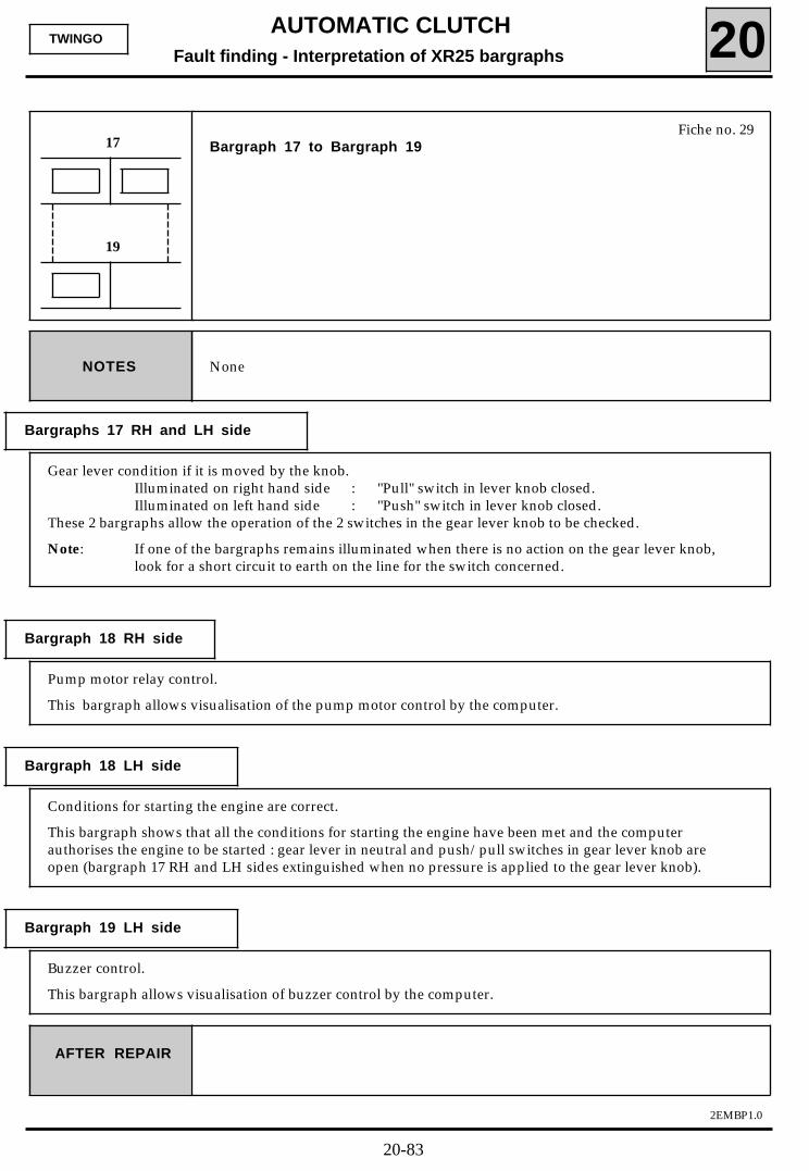
AUTOMATIC CLUTCHFault finding - Interpretation of XR25 bargraphs 20
2EMBP1.0
TWINGO
AFTER REPAIR
Fiche no. 29Bargraph 17 to Bargraph 1917
NoneNOTES
Gear lever condition if it is moved by the knob.Illuminated on right hand side : "Pull" switch in lever knob closed.Illuminated on left hand side : "Push" switch in lever knob closed.
These 2 bargraphs allow the operation of the 2 switches in the gear lever knob to be checked.
Note: If one of the bargraphs remains illuminated when there is no action on the gear lever knob,look for a short circuit to earth on the line for the switch concerned.
19
Pump motor relay control.
This bargraph allows visualisation of the pump motor control by the computer.
Conditions for starting the engine are correct.
This bargraph shows that all the conditions for starting the engine have been met and the computerauthorises the engine to be started : gear lever in neutral and push/pull switches in gear lever knob areopen (bargraph 17 RH and LH sides extinguished when no pressure is applied to the gear lever knob).
Buzzer control.
This bargraph allows visualisation of buzzer control by the computer.
Bargraphs 17 RH and LH side
Bargraph 18 RH side
Bargraph 18 LH side
Bargraph 19 LH side
20-83
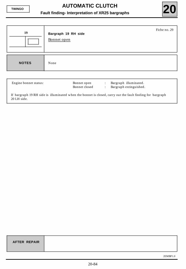
AUTOMATIC CLUTCHFault finding- Interpretation of XR25 bargraphs 20
2EMBP1.0
TWINGO
Fiche no. 29Bargraph 19 RH side
Bonnet open
19
NoneNOTES
AFTER REPAIR
Engine bonnet status: Bonnet open : Bargraph illuminated.Bonnet closed : Bargraph extinguished.
If bargraph 19 RH side is illuminated when the bonnet is closed, carry out the fault finding for bargraph20 LH side.
20-84
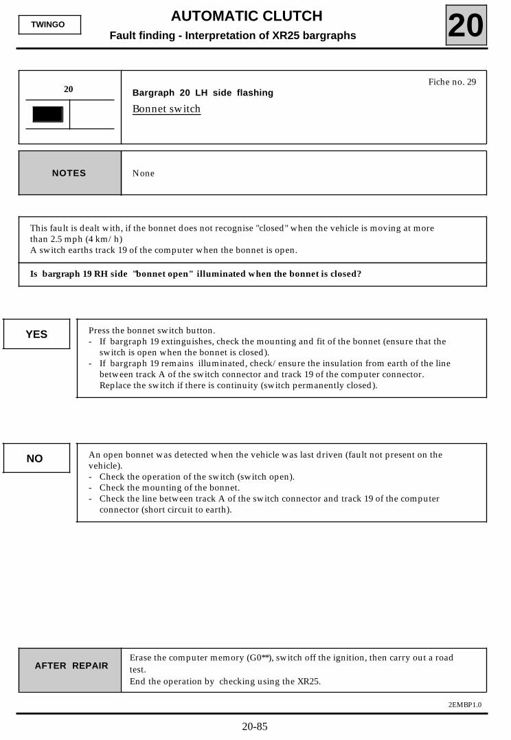
AUTOMATIC CLUTCHFault finding - Interpretation of XR25 bargraphs 20
2EMBP1.0
TWINGO
Fiche no. 29Bargraph 20 LH side flashing
Bonnet switch
20
NoneNOTES
AFTER REPAIRErase the computer memory (G0**), switch off the ignition, then carry out a roadtest.End the operation by checking using the XR25.
Is bargraph 19 RH side "bonnet open" illuminated when the bonnet is closed?
YES Press the bonnet switch button.- If bargraph 19 extinguishes, check the mounting and fit of the bonnet (ensure that the
switch is open when the bonnet is closed).- If bargraph 19 remains illuminated, check/ensure the insulation from earth of the line
between track A of the switch connector and track 19 of the computer connector.Replace the switch if there is continuity (switch permanently closed).
NO An open bonnet was detected when the vehicle was last driven (fault not present on thevehicle).- Check the operation of the switch (switch open).- Check the mounting of the bonnet.- Check the line between track A of the switch connector and track 19 of the computer
connector (short circuit to earth).
This fault is dealt with, if the bonnet does not recognise "closed" when the vehicle is moving at morethan 2.5 mph (4 km/h)A switch earths track 19 of the computer when the bonnet is open.
20-85
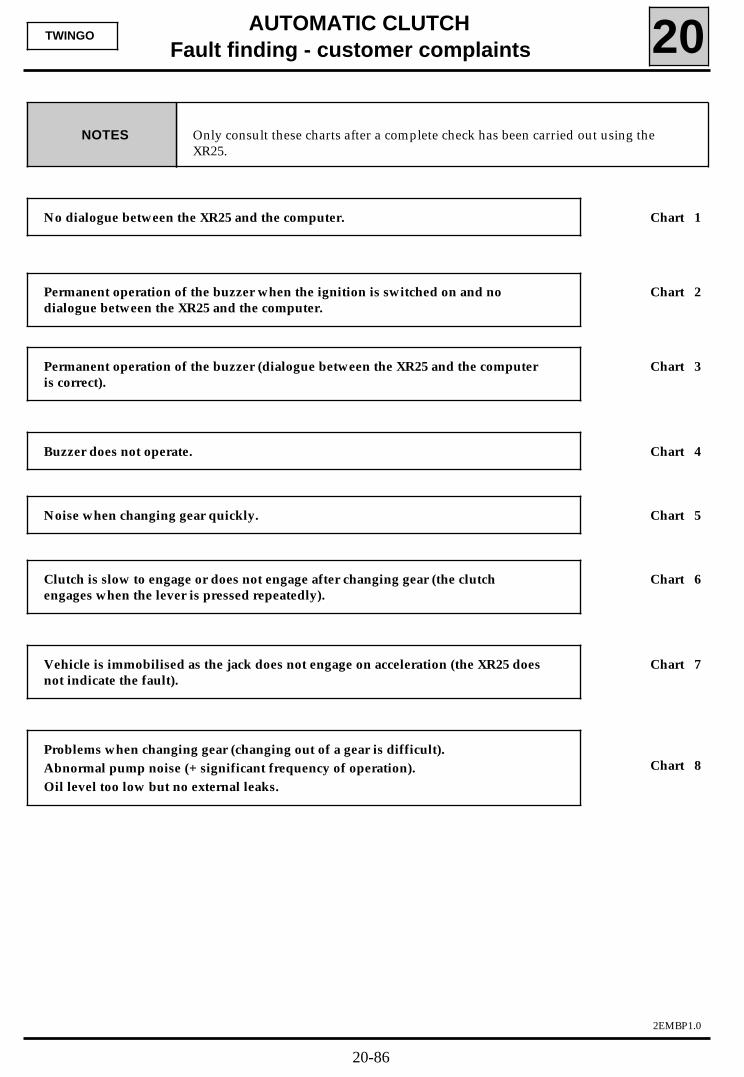
AUTOMATIC CLUTCHFault finding - customer complaints 20
2EMBP1.0
TWINGO
Only consult these charts after a complete check has been carried out using theXR25.
NOTES
No dialogue between the XR25 and the computer. Chart 1
Permanent operation of the buzzer when the ignition is switched on and nodialogue between the XR25 and the computer.
Chart 2
Permanent operation of the buzzer (dialogue between the XR25 and the computeris correct).
Chart 3
Buzzer does not operate. Chart 4
Noise when changing gear quickly. Chart 5
Clutch is slow to engage or does not engage after changing gear (the clutchengages when the lever is pressed repeatedly).
Chart 6
Vehicle is immobilised as the jack does not engage on acceleration (the XR25 doesnot indicate the fault).
Chart 7
Problems when changing gear (changing out of a gear is difficult). Abnormal pump noise (+ significant frequency of operation).Oil level too low but no external leaks.
Chart 8
20-86
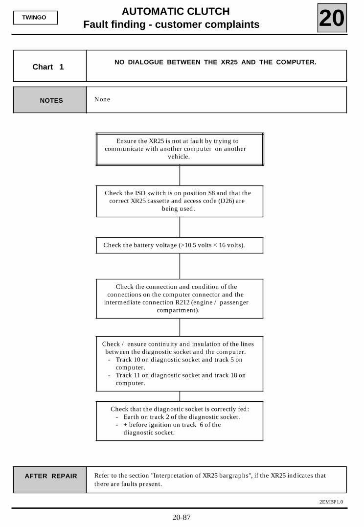
AUTOMATIC CLUTCHFault finding - customer complaints 20
2EMBP1.0
TWINGO
None NOTES
Chart 1NO DIALOGUE BETWEEN THE XR25 AND THE COMPUTER.
Ensure the XR25 is not at fault by trying tocommunicate with another computer on another
vehicle.
Check the ISO switch is on position S8 and that thecorrect XR25 cassette and access code (D26) are
being used.
Check the battery voltage (>10.5 volts < 16 volts).
Check the connection and condition of theconnections on the computer connector and the
intermediate connection R212 (engine / passengercompartment).
Check / ensure continuity and insulation of the linesbetween the diagnostic socket and the computer.- Track 10 on diagnostic socket and track 5 on
computer.- Track 11 on diagnostic socket and track 18 on
computer.
Check that the diagnostic socket is correctly fed:- Earth on track 2 of the diagnostic socket.- + before ignition on track 6 of the
diagnostic socket.
Refer to the section "Interpretation of XR25 bargraphs", if the XR25 indicates thatthere are faults present.
AFTER REPAIR
20-87
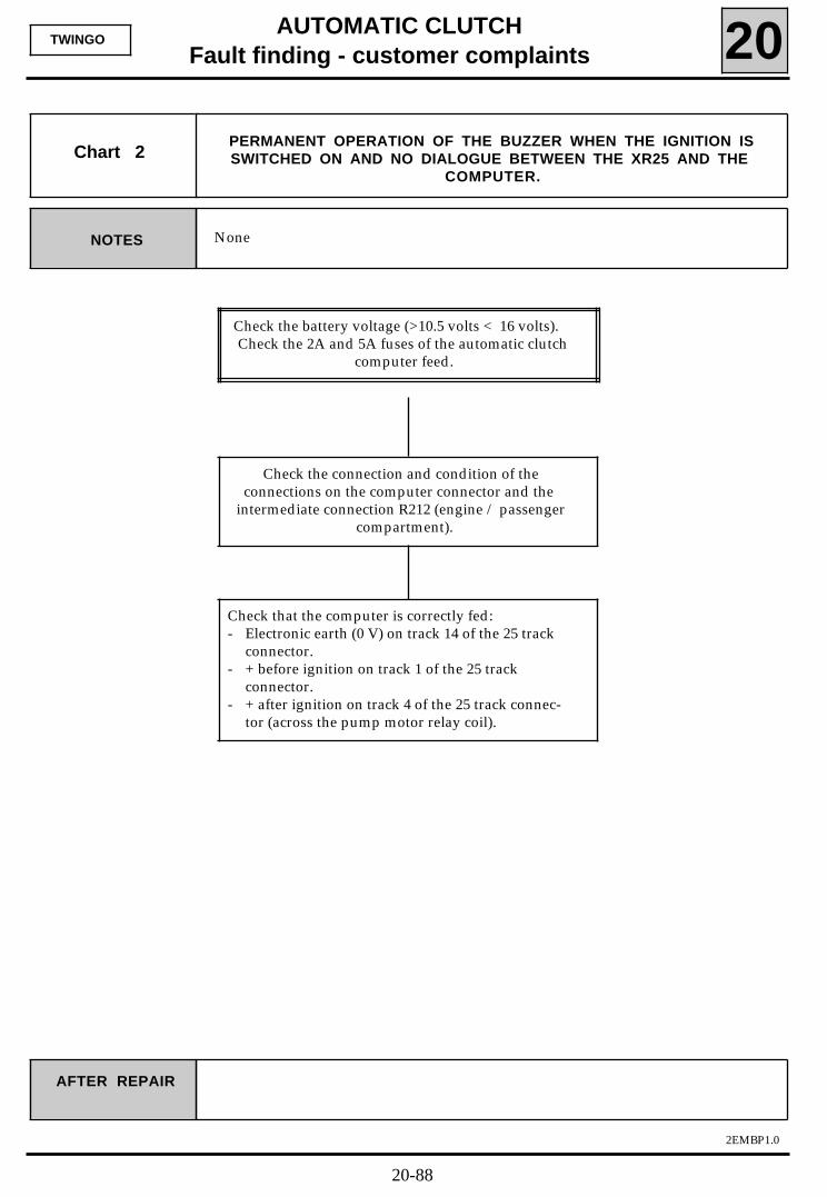
AUTOMATIC CLUTCHFault finding - customer complaints 20
2EMBP1.0
TWINGO
None NOTES
Chart 2PERMANENT OPERATION OF THE BUZZER WHEN THE IGNITION ISSWITCHED ON AND NO DIALOGUE BETWEEN THE XR25 AND THE
COMPUTER.
AFTER REPAIR
Check the battery voltage (>10.5 volts < 16 volts).Check the 2A and 5A fuses of the automatic clutch
computer feed.
Check the connection and condition of theconnections on the computer connector and the
intermediate connection R212 (engine / passengercompartment).
Check that the computer is correctly fed:- Electronic earth (0 V) on track 14 of the 25 track
connector.- + before ignition on track 1 of the 25 track
connector.- + after ignition on track 4 of the 25 track connec-
tor (across the pump motor relay coil).
20-88
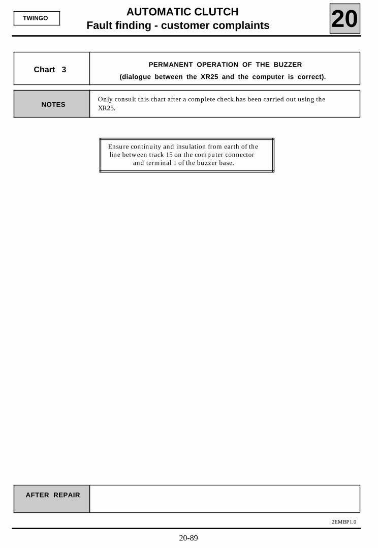
AUTOMATIC CLUTCHFault finding - customer complaints 20
2EMBP1.0
TWINGO
Only consult this chart after a complete check has been carried out using theXR25. NOTES
Chart 3PERMANENT OPERATION OF THE BUZZER
(dialogue between the XR25 and the computer is correct).
AFTER REPAIR
Ensure continuity and insulation from earth of theline between track 15 on the computer connector
and terminal 1 of the buzzer base.
20-89
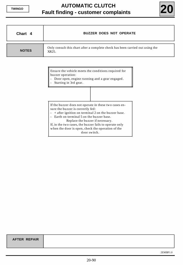
AUTOMATIC CLUTCHFault finding - customer complaints 20
2EMBP1.0
TWINGO
Only consult this chart after a complete check has been carried out using theXR25. NOTES
Chart 4 BUZZER DOES NOT OPERATE
AFTER REPAIR
Ensure the vehicle meets the conditions required forbuzzer operation:- Door open, engine running and a gear engaged.- Starting in 3rd gear.
If the buzzer does not operate in these two cases en-sure the buzzer is correctly fed:- + after ignition on terminal 2 on the buzzer base.- Earth on terminal 5 on the buzzer base.
Replace the buzzer if necessary.If, in the two cases, the buzzer fails to operate onlywhen the door is open, check the operation of the
door switch.
20-90

AUTOMATIC CLUTCHFault finding - customer complaints 20
2EMBP1.0
TWINGO
Only consult this chart after a complete check has been carried out using theXR25. NOTES
Chart 5 NOISE WHEN CHANGING GEAR QUICKLY.
AFTER REPAIR
Check that bargraphs 17 RH side and LH sideoperate correctly according to whether the lever
is pushed or pulled.
If bargraphs 17 never illuminate, disconnect the 3track connector from the bottom of the gear lever
and check/ensure continuity with earth of track C onthe harness side.
If only bargraph 17 RH side does not operatecorrectly, ensure continuity between track B on the 3
track connector and track 12 on the computerconnector. If continuity is established, check the
operation of the switch in the gear lever knob usinga multimeter and replace the lever if it is faulty.
If only bargraph 17 LH side does not operatecorrectly, ensure continuity between track A on the 3
track connector and track 13 on the computerconnector. If continuity is established, check the
operation of the switch in the gear lever knob usinga multimeter and replace the lever if it is faulty.
In all cases, follow the procedure for programmingthe gears.
20-91
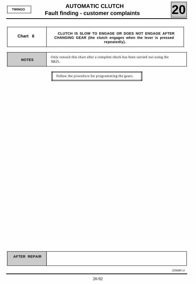
AUTOMATIC CLUTCHFault finding - customer complaints 20
2EMBP1.0
TWINGO
NOTESOnly consult this chart after a complete check has been carried out using theXR25.
Chart 6
AFTER REPAIR
Follow the procedure for programming the gears.
CLUTCH IS SLOW TO ENGAGE OR DOES NOT ENGAGE AFTERCHANGING GEAR (the clutch engages when the lever is pressed
repeatedly).
20-92
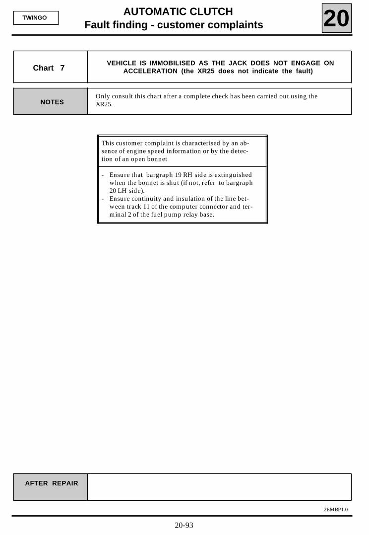
This customer complaint is characterised by an ab-sence of engine speed information or by the detec-tion of an open bonnet
- Ensure that bargraph 19 RH side is extinguishedwhen the bonnet is shut (if not, refer to bargraph20 LH side).
- Ensure continuity and insulation of the line bet-ween track 11 of the computer connector and ter-minal 2 of the fuel pump relay base.
AUTOMATIC CLUTCHFault finding - customer complaints 20
2EMBP1.0
TWINGO
Only consult this chart after a complete check has been carried out using theXR25. NOTES
Chart 7VEHICLE IS IMMOBILISED AS THE JACK DOES NOT ENGAGE ON
ACCELERATION (the XR25 does not indicate the fault)
AFTER REPAIR
20-93
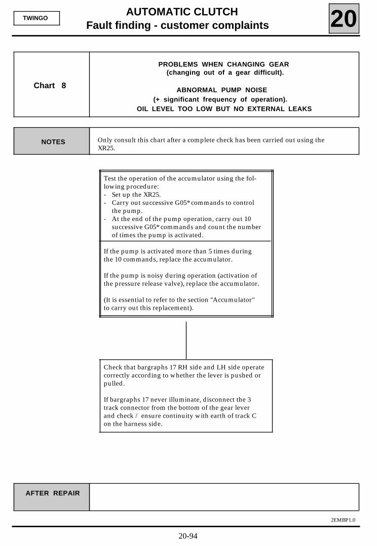
AUTOMATIC CLUTCHFault finding - customer complaints 20
2EMBP1.0
TWINGO
Test the operation of the accumulator using the fol-lowing procedure:- Set up the XR25.- Carry out successive G05* commands to control
the pump.- At the end of the pump operation, carry out 10
successive G05* commands and count the numberof times the pump is activated.
If the pump is activated more than 5 times duringthe 10 commands, replace the accumulator.
If the pump is noisy during operation (activation ofthe pressure release valve), replace the accumulator.
(It is essential to refer to the section "Accumulator"to carry out this replacement).
Only consult this chart after a complete check has been carried out using theXR25.
NOTES
Chart 8
PROBLEMS WHEN CHANGING GEAR (changing out of a gear difficult).
ABNORMAL PUMP NOISE (+ significant frequency of operation).
OIL LEVEL TOO LOW BUT NO EXTERNAL LEAKS
AFTER REPAIR
Check that bargraphs 17 RH side and LH side operatecorrectly according to whether the lever is pushed orpulled.
If bargraphs 17 never illuminate, disconnect the 3track connector from the bottom of the gear leverand check / ensure continuity with earth of track Con the harness side.
20-94
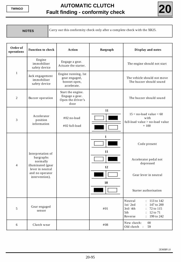
AUTOMATIC CLUTCHFault finding - conformity check 20
2EMBP1.0
TWINGO
Order ofoperations
Function to check Action Bargraph Display and notes
Engineimmobilisersafety device
Engage a gear. Actuate the starter. The engine should not start
Jack engagementimmobilisersafety device
Engine running, 1stgear engaged,bonnet open,
accelerate.
The vehicle should not moveThe buzzer should sound
2 Buzzer operation
Start the engine.Engage a gear.
Open the driver’sdoor
The buzzer should sound
3Accelerator
positioninformation
#02 no-load
#02 full-load
15 < no-load value < 60with
full-load value > no-load value+ 100
4
Interpretation ofbargraphsnormally
illuminated (gearlever in neutraland no operatorintervention).
Code present
Accelerator pedal notdepressed
Gear lever in neutral
Starter authorisation
5 Gear engagedsensor #01
Neutral : 113 to 1421st/2nd : 147 to 2003rd/4th : 72 to 1155th : 12 to 71Reverse : 199 to 242
6 Clutch wear #08 New clutch: 00Old clutch : 59
11
1
11
12
18
1
NOTES Carry out this conformity check only after a complete check with the XR25.
20-95
AUTOMATIC CLUTCHFault finding - XR25 aid 20
2EMBP1.0
TWINGO
Programming to be carried out according to the type of operation:
Programme gears using the G22* command after
Replacing the computer.Replacing/removing the engaged gear sensor.Removing the gearbox.Removing the gear lever or linkage.
Programme full-load and no-load positions for the accelerator using the G20* command after
Replacing the computer.Replacing/removing the injection potentiometer - modifying the accelerator control adjustment.
Programme the neutral position for the solenoid / clutch slip point and jack position after(NOTE: this programme resets "clutch wear" information, available on #08, to zero)
Replacing/removing the clutch jackReplacing/removing the hydraulic assemblyReplacing the clutchModifying the jack cable adjustment on the fork.
20-96