service advisor illustrated technical guide -...
TRANSCRIPT

Service AdvisorIllustrated Technical Guide

Drawing Page
L4 Engine......................................................................... 1
L4 Engine - Exploded View.............................................2
V6 Engine.........................................................................3
V6 Engine - Exploded View............................................ 4
Oil Filter ...........................................................................5
VTEC (Variable Timing Electronic Control) System......6
Fuel and Air Intake Systems............................................ 7
Evaporative Emissions System........................................ 8
Exhaust Systems...............................................................9
Automatic Transmission.................................................10
Clutch Assembly.............................................................11
4-Wheel Drive System (VTM-4)................................... 12
Driveshafts and CV (Constant Velocity) Joint Boots.... 13
Rack and Pinion Steering...............................................14
VSA (Vehicle Stability Assist) and TCS
(Traction Control System)......................................... 15
Drawing Page
Front Suspension............................................................16
Rear Suspension............................................................. 17
Tire Wear and Wheel Alignment....................................18
ABS (Anti-lock Brake System)......................................19
Conventional Brake System (non-ABS)........................20
Doors and Windows....................................................... 21
Engine Cooling and Vehicle Heating Systems...............22
Air Conditioning System................................................23
Starting and Charging System........................................24
Direct Ignition System................................................... 25
Distributor Ignition System............................................26
Hybrid IMA (Integrated Motor Assist) System............. 27
Audio and Entertainment Systems.................................28
Navigation System (with HandsFreeLink, if equipped)........ 29
SRS (Supplemental Restraint System)...........................30
Odyssey Power Sliding Doors........................................31
Contents

Water Pump
Valves
Rocker Arms
Camshafts
OilFilter
Belt Tensioner
TimingChain
SINGLE OVERHEAD CAM DOUBLE OVERHEAD CAM
Drive belt
Oil Pump
Rocker Arms
Water Pump
Camshaft
Pistons
Balancer Shaft
ValvesTiming Belt
Belt Tensioner
Balancer Belt
1
L4 Engine

DistributorDistributorO-ring
Cylinder Head CoverCylinder HeadCover Gasket
RubberGrommets
IntakeManifold
IntakeManifoldGasket
Camshaft PulleyOil Filter
Water Pump
Water Pump Gasket
Timing BeltDrive Pulley
Oil Pan Gasket
Oil Pan Drain BoltDrain BoltCrush Washer
Oil Pan
EngineBlock
Exhaust ManifoldGasket
Exhaust ManifoldHeadGasket
Cylinder Head
Oil Filter Gasket
2
L4 Engine - Exploded View

Water Pump
Valves
Rocker Arms
Camshaft
Pistons
Connecting Rod
Crankshaft
Belt Tensioner
Timing Belt
3
V6 Engine

Throttle BodyIntake Manifold Gasket
Cylinder Head Cover
CylinderHead CoverGasket
Cylinder Head
Rubber Grommets
Cylinder Head Gasket
Main Seal
Cover
Engine Block
Oil Pan
Oil PanDrain BoltOil PumpOil Filter
Oil FilterGasket
WaterPump
ExhaustManifold
Exhaust Manifold Gasket
Intake Manifold Gasket
Intake Manifold
Oil Pump Pickup
4
V6 Engine - Exploded View

5
Oil Filter
Oil flow throughthe filter
Oil BypassValve

6
Low-rpmOperation
For good fuel economy andsmooth operation, both valvesfollow the smaller cam lobes,providing passenger-car-typeperformance at low enginerpm (revolutions per minute).
Transition
AdjustableValves
LockingPin
Low-rpmCam Lobes
High-rpmCam Lobe
PrimaryRocker Arm
MidRockerArm Secondary
Rocker Arm
Horsepower rises steadily acrossthe switch-over point to provide asmooth transition between thelow-rpm and high-rpm modes ofengine operation.
High-rpmOperation
For higher engine power output,both valves follow the larger, centercam lobe, providing performance athigh rpm that is similar to a racingcar engine.
1
23
VTEC (Variable Timing Electronic Control) System

Fuel Rail
ThrottleBody
Fuel Tank
Fuel Fill Cap
Fuel FeedLine
MapSensor
ThrottleCables
ButterflyValve
FuelFilterFuel
GaugeSendingUnit Fuel
PressureRegulator
FuelPump
Suction Filter
Air Cleaner
Resonator
THROTTLEBODY
FUEL TANK UNIT
ThrottlePositionSensor
FuelPumpSealingRing
7
Fuel and Air Intake Systems

EvaporativeTwo-way Valve
EvaporativeEmissionCanister
Fuel TankVapor Control Valve
Fuel Pump VaporRecirculationTube
FuelFill Cap
Fuel Tank
Vent Hose
Fuel TankPressure Sensor
Canister Vent ValveEvaporativeCanisterPurge Valve
8
Evaporative Emissions System

Primary HeatedOxygen Sensor
ExhaustPipe "A"
ExhaustManifold
Exhaust Pipe "A"
Primary HeatedOxygen Sensor
ECM/PCM
Mid Pipe
Secondary HeatedOxygen Sensor
ExhaustPipe Tip
Muffler
Exhaust Pipe "B"
Catalytic Converter
Warm-up CatalyticConverters
CatalyticConverter
ECM/PCM
Mufflers
Exhaust Pipe "B"
Secondary HeatedOxygen Sensor
9
Exhaust Systems

Transmission Gears
Clutch Pack Assembly(1st Clutch and 2nd Clutch)
Torque ConverterAssemblyTorque Converter
Lock-up ControlSolenoid Valve Assembly
Shift ControlSolenoid ValveAssembly
Differential
Driveshaft
Clutch Pack Assembly(3rd Clutch and 4th Clutch)
10
Automatic Transmission

Clutch DiscClutchDamper
ReleaseBearing
PressurePlate
Clutch Disc
Flywheel
CrankshaftReleaseBearing
ReleaseFork
Clutch Interlock Switch
ClutchSwitch
ClutchPedal
PushRod
Clutch MasterCylinder
SlaveCylinder Flywheel
DISENGAGED POSITION
ENGAGED POSITION
11
Clutch Assembly

12
4-Wheel Drive System (VTM-4)
TransferGear Assembly
Transmission
ABS ModulatorAssembly
PCM
VTM-4Control Unit
Pinion Gear
Ring Gear
Electromagnetic Coil
Electromagnetic Coil
Propeller Shaft
Wheel Sensors
Clutch
Clutch

Driveshaft
Boot Bands
Boot Bands
InboardCV Joint
OutboardCV Joint
DriveshaftIntermediate ShaftCarrier Bearing
IntermediateShaft
Transaxle
Boot
Boot
13
Driveshafts and CV (Constant Velocity) Joint Boots
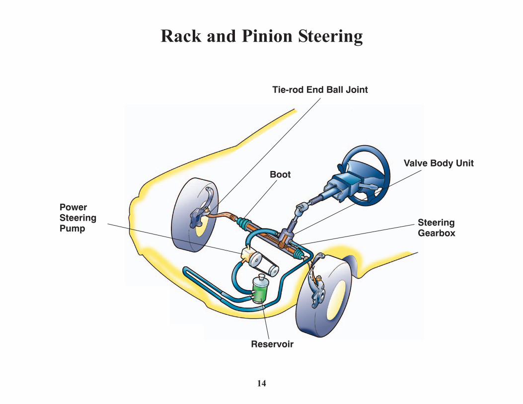
Tie-rod End Ball Joint
Valve Body Unit
SteeringGearbox
Boot
Reservoir
PowerSteeringPump
Visually inspect tie-rod ends,
steering gearbox and boots
every 15,000 miles
Under severe operating conditions,
visually inspect tie-rod ends, steering
gearbox and boots every 7,500 miles
Rotate tires every 7,500 miles
14
Rack and Pinion Steering

Without VSAWith VSA
Without VSA
Without TCS
With TCS
With VSABrakes areapplied tooutside wheels.
Brakes areapplied toinside wheels.
Right FrontWheel Sensor
Yaw-rate LateralAcceleration Sensor
ABS/TCSControlUnit
Steering Angle Sensor
Right RearWheel Sensor
Left FrontWheel Sensor
ABS/VSAModulator
Left RearWheel Sensor
15
VSA (Vehicle Stability Assist) and
TCS (Traction Control System)

Upper Control ArmDamper(Shock Absorber)
Coil Spring
Stabilizer Bar
StabilizerBar Bushing
Lower Control ArmDamper Fork
Driveshaft BootRadius Rod
Radius RodRubber Bushing
Ball Joint
BallJointBoot
Castle Nut
Knuckle
16
Front Suspension

Coil SpringDamper (Shock Absorber)
Upper Control Arm
Stabilizer Bar Bracket
Stabilizer Bar Bushing
StabilizerBar
Damper
Coil Spring
Stabilizer BarBracket/Bushing
Stabilizer Bar
Trailing Arm
Trailing ArmBracket
Lower ControlArm "B"
Lower Control Arm
Trailing ArmBushing
Trailing Arm
Compensator Arm
Lower ControlArm "A"
UpperControl Arm
Knuckle
17
Rear Suspension

WearIndicator
LocalWear
Diagonal Wear/Heel and Toe Wear
Spotty/Chopped
Wear(multiproblem)
FeatheredWear
(excessive toein or out)
CamberWear
Overinflation UnderinflationNegative Camber Positive Camber
Toe In Toe Out
Negative Caster Positive Caster
18
Tire Wear and Wheel Alignment

Control Module Brake Booster
MasterCylinder
Modulator Unit
Wheel Sensors
WheelSensor
GearPulser
Brake Disc
Wheel Sensors
19
ABS (Anti-lock Brake System)

Hydraulic Lines
Brake Booster
Master Cylinder
Front Disc Brakes
Wear Indicator
BrakeCaliper
Piston
Brake Pads
BrakeDisc
Drum Parking Brake(inside rear disc brake)
ParkingBrakeShoes
ParkingBrakeCables
ParkingBrake Lever
Rear Disc Brakes
20
Conventional Brake System (non-ABS)

Latch
Power Window Motor
NEW STYLEPOWER WINDOWS
OLD STYLEPOWER WINDOWS
MANUAL WINDOWS
Inner Door Handle
Door Checker Hinges
Front Window Channel
Power Window Switch
Window Regulator
Window Regulator
RegulatorHandle
CenterLower Channel
Power Door Lock Actuator
21
Doors and Windows

Heater Core
HeaterValve
ThermostatHousing
CoolantReservoir
Radiator
Radiator Fan Water Pump
TemperatureControl Dial
TransmissionCooler
RadiatorCap Radiator
Hoses
Heater Hoses
22
Engine Cooling and Vehicle Heating Systems

Micron Filter
Pollenand DustEvaporator and
Heater Core(under dash)
Blower
Service Valves
Receiver/Dryer
Condenser FanCondenser Compressor
Compressor Belt
CondensationDrain Tube
Expansion Valve
23
Air Conditioning System

Under-hoodFuse Box
Battery
Starter
Starter Solenoid
Alternator Alternator Belt
LockCylinder
Charging System Light
ECM/PCM
Immobilizer ControlUnit-receiver
Ignition KeyTransponder
To the Fuel System
Ignition Switch
KeyCylinder
IMMOBILIZER SYSTEM
24
Starting and Charging System
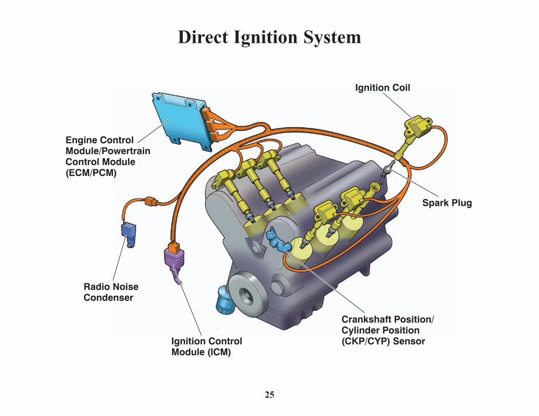
Engine ControlModule/PowertrainControl Module(ECM/PCM)
Radio NoiseCondenser
Ignition ControlModule (ICM)
Crankshaft Position/Cylinder Position(CKP/CYP) Sensor
Spark Plug
Ignition Coil
25
Direct Ignition System

26
Distributor Ignition System
Distributor
SparkPlugWires
Distributor Cap
Rotor
Ignition ControlModule (ICM)
Housing
Coil (external)
Coil (internal)
Engine Control Module/Powertrain ControlModule (ECM/PCM)
SparkPlugs

27
Hybrid IMA (Integrated Motor Assist) System
Auto Idle Stop Indicator
Gasoline Engine
Electric MotorTransmission
Cooling Fan
Cooling Fan DuctConverter
Storage Battery
Battery
IMA MotorPower Cable
Power Drive Unit(PDU) Transmission

Tweeters Stereo AmplifierDVD System
Antenna ModuleWindow Antenna
XM Antenna
XM Receiver
Subwoofer
Audio Unit
Audio Remote Switch
28
Audio and Entertainment Systems

Display PanelControl Unit Audio/HVAC
Subdisplay/ClockMicrophone
HandsFreeLinkControl Unit
ECM/PCM
GPSSatellites(24 total)
GPS Antenna
Yaw/PitchSensor
Navigation Unit
Map DVD-ROMNavigationTalk-BackButtons
TransmissionCountershaftSpeed Sensor
29
Navigation System (with HandsFreeLink, if equipped)

Front Passenger'sAirbag
SRS Indicator
Driver's Airbag
AirbagDeployment
Side CurtainAirbags(if equipped)
Side ImpactSensor(second)
Side Airbag
Front SeatBelt Tensioner(if equipped)
Side Impact Sensor (first)
Cable Reel
Under-dashFuse/Relay Box
Front Impact Sensor(if equipped)
Gold PlatedElectricalConnectors
SRS Unit(including"G" Sensors)
30
SRS (Supplemental Restraint System)

Junction SwitchAssemblies
OLD STYLE
NEW STYLE
Remote ControlAssembly
FailsafeLeverCable Release
Cable
Power Sliding DoorControl Unit
Slide Motor
LatchAssembly
Lower RollerLever Cable
Lower RollerLever
Power SlidingDoor TouchSensor Remote Control
Assembly Door ReleaseActuator
Power SlideMotor
Rear LatchCESSArticulatedHarness
LowerRollerLever
Front Latch
31
Odyssey Power Sliding Doors

Y0416 ©2005 American Honda Motor Co., Inc. Printed in U.S.A.