noble and precious metals study support miroslav...
TRANSCRIPT
Noble and precious metals
Study Support
Miroslav Kursa, Ivo Szurman
Ostrava 2015
VYSOKÁ ŠKOLA BÁŇSKÁ – TECHNICKÁ UNIVERZITA OSTRAVA
FAKULTA METALURGIE A MATERIÁLOVÉHO INŽENÝRSTVÍ
Title: Noble and precious metals
Code:
Author: Miroslav Kursa, Ivo Szurman
Edition: first, 2015
Number of pages: 66
Academic materials for the Advanced Engineering Materials study programme at the
Faculty of Metallurgy and Materials Engineering.
Proofreading has not been performed.
Execution: VŠB - Technical University of Ostrava

Contents 1. Introduction ........................................................................................................................ 7
2. Precious metals ................................................................................................................... 7
2.1 Gold .................................................................................................................................. 7
2.1.1 Gold properties .......................................................................................................... 8
2.1.2 Gold compounds ....................................................................................................... 8
2.1.3 Production technology ............................................................................................. 11
2.1.3.1 Cyanide process of gold extraction .................................................................. 11
2.1.3.1 Production of gold from anode sludge after electrolysis of copper ................. 15
2.1.4 Gold refining ........................................................................................................... 15
2.1.4.1 Electrolytic refining of gold ............................................................................. 15
2.1.5 Application of gold .................................................................................................. 16
2.1.6 Gold alloys .............................................................................................................. 16
2.2 Silver .............................................................................................................................. 17
2.2.1 Silver properties ...................................................................................................... 18
2.2.2 Silver compounds .................................................................................................... 18
2.2.3 Production technology ............................................................................................. 19
2.2.3.1 Hydrometallurgic processes of silver extraction .............................................. 19
2.2.3.2 Pyrometallurgic production of silver from lead ores........................................ 20
2.2.4 Refining of raw silver .............................................................................................. 21
2.2.4.1 Electrolytic refining of silver ........................................................................... 21
2.2.5 Application of silver and silver alloys ..................................................................... 22
2.3 Platinum and platinum group metals .............................................................................. 24
2.3.1 Properties of platinum group metals ....................................................................... 24
2.3.1.1 Platinum ........................................................................................................... 24
2.3.1.2 Palladium .......................................................................................................... 24
2.3.1.3 Iridium .............................................................................................................. 24
2.3.1.4 Rhodium ........................................................................................................... 25
2.3.1.5 Osmium ............................................................................................................ 25
2.3.1.6 Ruthenium ........................................................................................................ 25
2.3.2 Production technology of platinum metals. ............................................................. 25
2.3.2.1 Amalgamation of platinum and metals of the platinum group ......................... 26
2.3.2.2 Chlorination of platinum ores .......................................................................... 26
2.3.2.3 Affination of platinum metals .......................................................................... 27
2.3.3 Application of platinum metals ............................................................................... 28
2.3.4 Alloys ...................................................................................................................... 28
2.3.4.1 Pt alloys ............................................................................................................ 28
2.3.4.2 Pd alloys ........................................................................................................... 29
3. Refractory metals ............................................................................................................. 29
3.1 Tungsten ......................................................................................................................... 30
3.1.1 Tungsten properties ................................................................................................. 30
3.1.2 Tungsten compounds ............................................................................................... 30
3.1.3 Tungsten production technology ............................................................................. 30
3.1.3.1 Caking with soda .............................................................................................. 31
3.1.3.2 Dissociation of wolframite concentrate by solution of sodium hydroxide ...... 31
3.1.3.3 Cleaning of sodium tungstate solutions ........................................................... 31
3.1.3.4 Obtaining of tungsten compounds .................................................................... 32
3.1.3.5 Preparation of tungsten oxide ........................................................................... 32
3.1.3.6 Preparation of metallic tungsten ....................................................................... 32
3.1.3.7 Preparation of compact tungsten ...................................................................... 33
3.1.4 Application of tungsten and tungsten alloys ........................................................... 34
3.2 Molybdenum .................................................................................................................. 34
3.2.1 Molybdenum properties .......................................................................................... 34
3.2.2 Compounds .............................................................................................................. 34
3.2.3 Production technology of molybdenum .................................................................. 35
3.2.3.1 Oxidation roasting of molybdenite concentrate ............................................... 35
3.2.3.2 Preparation of pure molybdenum oxide ........................................................... 36
3.2.3.3 Production of metallic molybdenum ................................................................ 37
3.2.3.4 Production of compact molybdenum ............................................................... 37
3.2.4 Application of molybdenum and molybdenum alloys ............................................ 37
3.3 Titanium ......................................................................................................................... 38
3.3.1 Titanium properties ................................................................................................. 38
3.3.2 Compounds .............................................................................................................. 38
3.3.3 Production technology of titanium .......................................................................... 39
3.3.3.1 Processing of concentrates to titanium dioxide ................................................ 39
3.3.3.2 Production of titanium tetrachloride ................................................................ 40
3.3.3.3 Production of metallic titanium ........................................................................ 40
3.3.4 Application and alloys ........................................................................................ 41
3.4 Zirconium and zirconium alloys..................................................................................... 42
3.4.1 Zirconium production .............................................................................................. 42
3.4.1.1 Processing methods of zircon concentrates ...................................................... 43
3.4.1.2 Production of zirconium tetrachloride .............................................................. 44
3.4.1.3 Separation of hafnium from zirconium (dehafnization) ................................... 44
3.4.1.4 Production of metallic zirconium by metallothermic method .......................... 44
3.4.2 Zirconium alloys ..................................................................................................... 45
3.4.2.1 Zr – Sn alloys ................................................................................................... 46
3.4.3 Corrosion of zirconium and its alloys ..................................................................... 46
3.4.3.1 Water ................................................................................................................ 46
3.5 Niobium .......................................................................................................................... 47
3.5.1 Niobium production ................................................................................................ 47
3.5.1.1 Separation of niobium and tantalum ................................................................ 48
3.5.1.2 Production of metallic niobium ........................................................................ 48
3.5.2 Niobium processing ................................................................................................. 49
3.5.3 Mechanical properties of niobium ........................................................................... 49
3.5.4 Niobium corrosion ................................................................................................... 49
3.6 Vanadium ....................................................................................................................... 50
3.6.1 Properties of vanadium and vanadium alloys ......................................................... 50
3.6.2 Preparation technology of vanadium ....................................................................... 50
3.6.2.1 Production of metallic vanadium ..................................................................... 51
3.6.3 Vanadium alloys and applications ........................................................................... 52
4. Radioactive metals ........................................................................................................... 53
4.1 Uranium .......................................................................................................................... 53
4.1.1 Metallic uranium ..................................................................................................... 53
4.1.1.1 Occurrence and uranium ores ........................................................................... 53
4.1.1.2 Uranium production ......................................................................................... 54
4.1.2 Physical and mechanical properties of uranium ...................................................... 58
4.1.3 Powder metallurgy of uranium ................................................................................ 59
4.1.4 Uranium alloys ........................................................................................................ 60
4.1.4.1 Uranium alpha alloys ....................................................................................... 60
4.1.4.2 Uranium gamma alloys .................................................................................... 60
4.1.7 Uranium alloys – ceramic fuels ............................................................................... 61
4.2 Thorium .......................................................................................................................... 62
4.2.1 Occurrence, ores and their enrichment .................................................................... 63
4.2.2 Thorium production ................................................................................................. 63
4.2.2.1 Preparation of pure thorium compounds .......................................................... 63
4.2.2.2 Preparation of metallic thorium ........................................................................ 64
4.2.3 Thorium properties .................................................................................................. 65
4.2.5 Thorium alloys ........................................................................................................ 65
STUDY INSTRUCTIONS
Students of the Noble and Precious Metals course in the 1st semester of the master's studies of
the field of Progressive Technical Materials receive a study package including lecture notes
and study instructions for the combined studies.
1. Prerequisites
The following courses are required to enrol in this course: Basics of Production of Non-
ferrous Metals and Metal Materials II - Non-ferrous Metals and their Alloys.
2. Course aim and learning outputs
After studying this module the students should be able to:
formulate the basic characteristics of this group of metals and alloys,
select the optimum material for different types of applications in terms of their
mechanical properties and interaction with the environment,
assess and propose optimum production technologies of individual metals and their
alloys,
assess or predict the impact of individual technological parameters on the production
process, its effectiveness and impact on the environment.
assess the effect of possible impurities on the use characteristics of the metals and their
alloys,
propose effective refining process for metals in this group.
knowledge:
Assess material requirements for concrete applications and modify them using the
alloying process, or alternatively using technical and mechanical processing.
Who this course is intended for
This course is offered in the Master's studies of the field of Progressive Technical Materials in
the Material Engineering study program but it can be taken by students from any other field
who meet the prerequisites.
The study materials are divided into sections, chapters, that correspond to the logical division
of the covered subject and have different lengths. The estimated time to study each chapter
can significantly differ and that is why long chapters are further divided into numbered
subchapters in accordance with the below described structure.
We recommend the following procedure for studying individual chapters:
Study each chapter thoroughly and answer the questions Any questions regarding the
covered subject can be discussed within consultations.
Communication with lecturers:
Students of the combined studies will be assigned programs and semestral projects on
lectures of the Noble and Precious Metals course. Communication with the lecturer will be
ensured in the form of consultations on arranged dates, alternatively via e-mail. The
requirements for passing the course will be discussed in detail during the introductory
lecture. Students will be provided sample tasks at the introductory lecture.
1. Introduction
Time to study: 0,5 hours
Lecture
Metals and their alloys that were not used very often in the past find increasing
application options in the current technological practice. These trends are given by specific
requirements of the practice and by the improvement of the production technology and
processing of these metals. The main reason behind this is to fully utilize certain properties of
materials, such as noble metals, refractory metals and radioactive metals. These metals, alloys
and compounds are the subject of this study material. Many of these metals have a wide range
of applications in electrotechnics and microelectronics, others are used in aviation technology
or rocketry. This group of materials includes both functional materials, which provide
interesting physical properties, favourable electrical conductivity, low or high density, and
constructional materials, which offer high oxidation resistance at high temperatures,
alternatively high mechanical characteristics at increased temperatures. As far as noble steels
are concerned, we will pay attention to Au, Ag and metals of the platinum group. In terms of
metals with high melting temperature, so called refractory metals, we will focus on W, Mo,
Ti, Zr, Hf, Nb, Ta and V. The last group of metals introduced in this study material is
radioactive metals, with attention paid especially to uranium and its possible forms suitable
for nuclear energy.
2. Precious metals
Time to study: 10 hours
Aim After studying this section the student should be able to:
Characterize the group of noble metals, become familiar with properties of
these metals.
Design concrete practical applications of noble metals with regards to the
required properties.
Lecture
2.1 Gold
Gold is one of the first metals used by people for working, since it could be found in
its pure form. People also knew how to cold-form gold by beating. Later on, gold was melted
and separated from silver. Already from the ancient times, gold was the indicator of value and
basis of all trade (thanks to its durability and values). First gold coins were minted in the 7th
century BC. In case of gold mining, the mined rock was crushed and gold was obtained by
gold-washing, as well as gravitation enrichment methods, floatation and amalgamation. The
most used method at present is cyanidation. In 2012 approximately 2700 tons of gold were
produced worldwide.
2.1.1 Gold properties
Gold is the only metal with yellow color and beautiful lasting gloss. Its density is
19.32 g.cm-3
. The melting temperature is 1063 °C. The boiling temperature of this metal is
2966°C; however, it starts to evaporate significantly already at 1100 °C. It has the KPC
lattice. Gold is the most malleable and ductile metal. Gold can be formed to a film with
thickness of only 0.0001 mm or it can be drawn to a wire with a diameter of 0.005 mm. Its
casting properties are excellent – it does not oxidize or absorb gases during the melting
process and it can be melted without any protection measures (flux agents, etc.). From the
chemical point of view, it is a high-resistance metal, which is related to its very high positive
potential. It is completely resistant to most acids, leaches and salts and it is easily extracted
from its alloys in the metal form. It is dissolved only in mercury (it forms an amalgam with
this metal); in cyanides and also for instance in aqua regie it forms a complex compound (1
HNO3 : 3 HCl). Purity of gold is measured in carats. Pure gold corresponds to 24 carats, from
which it follows that 1 carat is 41.66 ‰. Most commonly used gold for jewellery purposes
has 14 carats, i.e. 583.33 ‰.
2.1.2 Gold compounds
Gold in its compounds is either trivalent or monovalent. Trivalent gold is the most
stable. All gold compounds are easily dissociated thermally or by reducing agents.
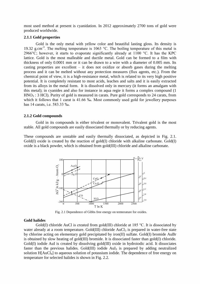
These compounds are unstable and easily thermally dissociated, as depicted in Fig. 2.1.
Gold(I) oxide is created by the reaction of gold(I) chloride with alkaline carbonate. Gold(I)
oxide is a black powder, which is obtained from gold(III) chloride and alkaline carbonate.
Gold halides
Gold(I) chloride AuCl is created from gold(III) chloride at 185 °C. It is dissociated by
water already at a room temperature. Gold(III) chloride AuCl3 is prepared in water-free state
by chlorine acting on elementary gold precipitated by iron(II) sulfate. Gold(I) bromide AuBr
is obtained by slow heating of gold(III) bromide. It is dissociated faster than gold(I) chloride.
Gold(I) iodide AuI is created by dissolving gold(III) oxide in hydroiodic acid. It dissociates
faster than the previous halides. Gold(III) iodide AuI3 is prepared by adding neutralized
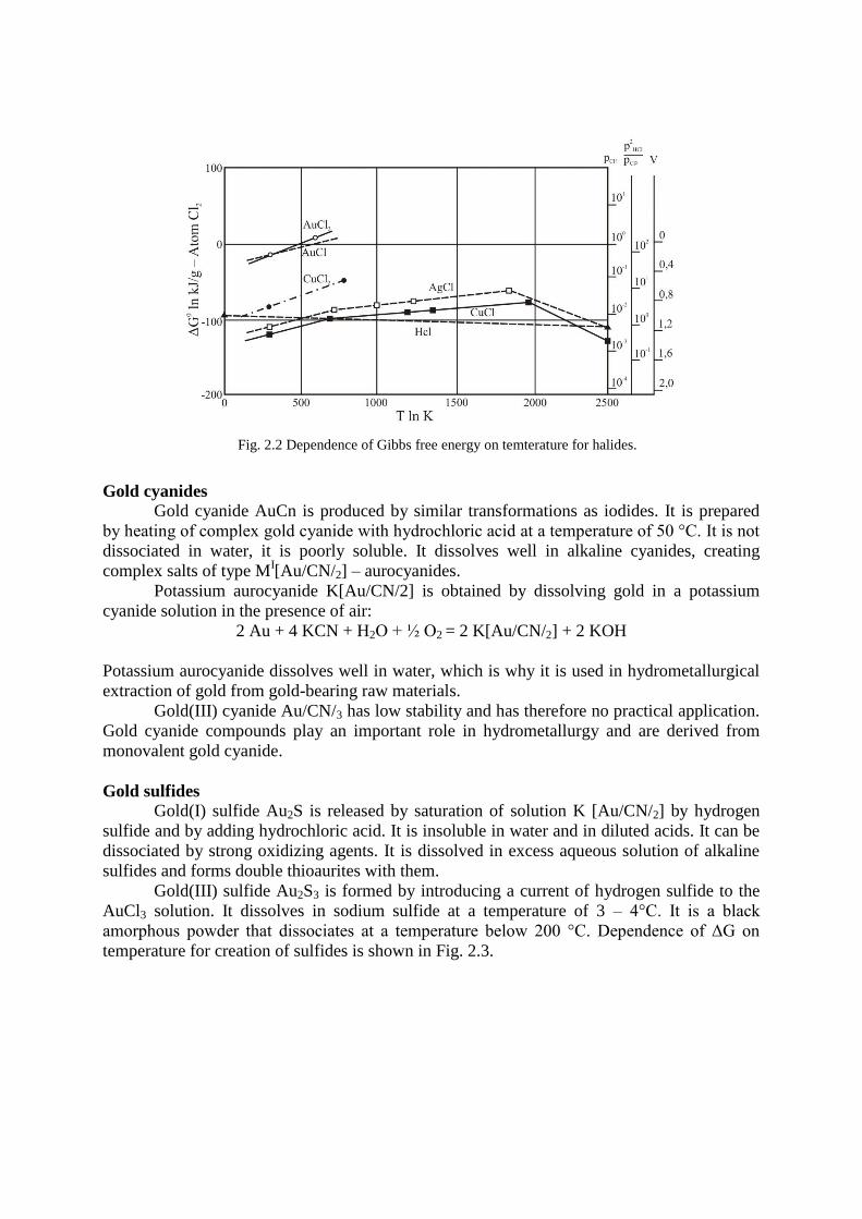
solution H[AuCl4] to aqueous solution of potassium iodide. The dependence of free energy on
temperature for selected halides is shown in Fig. 2.2.
Fig. 2.1 Dependence of Gibbs free energy on temterature for oxides.
Gold cyanides
Gold cyanide AuCn is produced by similar transformations as iodides. It is prepared
by heating of complex gold cyanide with hydrochloric acid at a temperature of 50 °C. It is not
dissociated in water, it is poorly soluble. It dissolves well in alkaline cyanides, creating
complex salts of type MI[Au/CN/2] – aurocyanides.
Potassium aurocyanide K[Au/CN/2] is obtained by dissolving gold in a potassium
cyanide solution in the presence of air:
2 Au + 4 KCN + H2O + ½ O2 = 2 K[Au/CN/2] + 2 KOH
Potassium aurocyanide dissolves well in water, which is why it is used in hydrometallurgical
extraction of gold from gold-bearing raw materials.
Gold(III) cyanide Au/CN/3 has low stability and has therefore no practical application.
Gold cyanide compounds play an important role in hydrometallurgy and are derived from
monovalent gold cyanide.
Gold sulfides
Gold(I) sulfide Au2S is released by saturation of solution K [Au/CN/2] by hydrogen
sulfide and by adding hydrochloric acid. It is insoluble in water and in diluted acids. It can be
dissociated by strong oxidizing agents. It is dissolved in excess aqueous solution of alkaline
sulfides and forms double thioaurites with them.
Gold(III) sulfide Au2S3 is formed by introducing a current of hydrogen sulfide to the
AuCl3 solution. It dissolves in sodium sulfide at a temperature of 3 – 4°C. It is a black
amorphous powder that dissociates at a temperature below 200 °C. Dependence of ΔG on
temperature for creation of sulfides is shown in Fig. 2.3.
Fig. 2.2 Dependence of Gibbs free energy on temterature for halides.

Gold sulfates
This compound is stable only in concentrated solutions of H2SO4. Dilution of the
solution immediately causes hydrolysis and creation of gold(III) hydroxide. Similar process
applies for gold(III) carbonate. These compounds appear in solutions in the form of complex
compounds.
Gold telluride AuTe2
This compound occurs in nature as the mineral calaverite. It is dissociated when
heated in the air. It can amalgamate directly and dissolves in solution of alkaline cyanides,
especially if cyanogen bromide is present:
2 Au + BrCN + 3 KCN = 2 K[Au/CN/2] + KB
Gold amalgams
Amalgams are systems, in which one component consists of mercury. Under normal
conditions, Hg takes a liquid form; however, amalgam containing semi-free mercury
constitutes a semi-liquid compound.
In addition to precious metals, other metals also form amalgams with mercury –
alkaline metals, alkaline earth metals. Formation reaction of precious metal amalgams, as
opposed to other metals, are characterized by very low thermal effects. Such created
compounds are dissociated under the melting temperature while releasing the remaining
mercury.
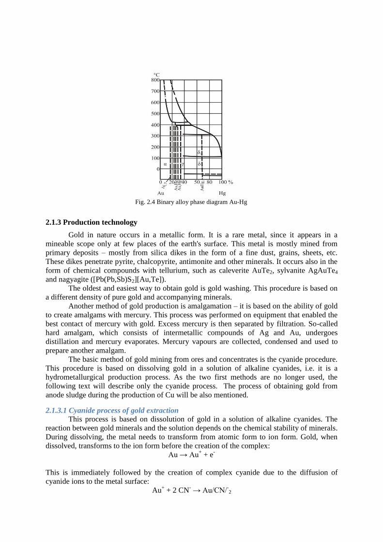
Fig. 2.4 shows a binary diagram of Au – Hg. Mercury forms three compounds with
Gold: AuHg2 (δ phase), Au2Hg (γ phase), Au3Hg (β phase) and a solid mercury solution with
the maximum concentration of 16.7 at. % Hg (α phase).
Solubility of gold in mercury at normal temperature ranges between 0.15 – 0.20 %. In
terms of their chemical composition, operation amalgams represent an interval between the
pure component (Hg) and amalgam with a 33% content of Au. These heterogeneous semi-
liquid compounds can be separated by filtration – in this case Hg represents the filtrate. In
addition, a non-negligible amount of gold is also dissolved in this mercury (approximately
0.15 – 0.17 %).
Fig. 2.3 Dependence of Gibbs free energy on temterature for sulfides.
2.1.3 Production technology
Gold in nature occurs in a metallic form. It is a rare metal, since it appears in a
mineable scope only at few places of the earth's surface. This metal is mostly mined from
primary deposits – mostly from silica dikes in the form of a fine dust, grains, sheets, etc.
These dikes penetrate pyrite, chalcopyrite, antimonite and other minerals. It occurs also in the
form of chemical compounds with tellurium, such as caleverite AuTe2, sylvanite AgAuTe4
and nagyagite ([Pb(Pb,Sb)S2][Au,Te]).
The oldest and easiest way to obtain gold is gold washing. This procedure is based on
a different density of pure gold and accompanying minerals.
Another method of gold production is amalgamation – it is based on the ability of gold
to create amalgams with mercury. This process was performed on equipment that enabled the
best contact of mercury with gold. Excess mercury is then separated by filtration. So-called
hard amalgam, which consists of intermetallic compounds of Ag and Au, undergoes
distillation and mercury evaporates. Mercury vapours are collected, condensed and used to
prepare another amalgam.
The basic method of gold mining from ores and concentrates is the cyanide procedure.
This procedure is based on dissolving gold in a solution of alkaline cyanides, i.e. it is a
hydrometallurgical production process. As the two first methods are no longer used, the
following text will describe only the cyanide process. The process of obtaining gold from
anode sludge during the production of Cu will be also mentioned.
2.1.3.1 Cyanide process of gold extraction
This process is based on dissolution of gold in a solution of alkaline cyanides. The
reaction between gold minerals and the solution depends on the chemical stability of minerals.
During dissolving, the metal needs to transform from atomic form to ion form. Gold, when
dissolved, transforms to the ion form before the creation of the complex:
Au → Au+ + e
-
This is immediately followed by the creation of complex cyanide due to the diffusion of
cyanide ions to the metal surface:
Au+ + 2 CN
- → Au/CN/
-2
Fig. 2.4 Binary alloy phase diagram Au-Hg
The most available oxidation agent in operating conditions is oxygen, which is contained in
the cyanide solution. The dissolving equation for gold in cyanide solution can be expressed as
follows:
2 Au + 4 KCN + ½ O2 + H2O → 2 K [Au/CN/2] + 2 KOH
Gold dissolution kinetics
For the sake of simplicity, the kinetics of this process can be summarized as follows:
Convection - balancing of concentration in the whole reaction volume.
Diffusion - plays an important role near the surface of the dissolved grain; it
determines the penetration speed of (CN)- and O2 by a so-called diffusion layer that
surrounds the grain.
Chemical composition of the metal - consists mainly of easily soluble admixtures
oxidable in Au.
Concentration of O2 - saturation of (CN)- solutions by O2. Leaching at increased air
pressure or leaching in oxygen atmosphere - autoclave - can be used.
Degree of mash dilution - ratio of solid to liquid phase p:k. This ratio influences the
solution viscosity and subsequently the speed of O2 diffusion in mash to gold.
Dimensions of gold particles - the surface area with which the cyanide solution reacts.
Loss of cyanide during leaching
The consumption of the cyanide solution is one of the main economic and technical
production indicators and is determined by chemical and mechanical factors. Loss of cyanide
can be prevented by adding a so-called protection base, mostly in the form of NaOH, to the
solution during the process. These alkalis protect cyanide salts from hydrolysis. The following
reaction occurs during the hydrolysis of cyanide compounds:
CN- + H2O = OH
- + HCN
This reaction produces a highly volatile compound HCN with a boiling temperature of 26.5
°C. It was determined that 0.01 % content of NaOH in the solution protects cyanide solution
against hydrolysis. However, the content of alkali must not exceed a certain limit to prevent
creation of thin layers on the surface of the dissolved gold.
Pure gold is most commonly accompanied by Fe minerals (pyrite, pyrrhotine).
Pyrrhotine is the most harmful of Fe sulfides, since its oxidation consumes a large amount of
oxygen from the solution.
Leaching methods of gold-bearing ores
These methods include percolation - seeping or leaching together with mixing.
Seeping is used to leach coarse-grained materials, which enable filtering of the solution
through a relatively high ore column. The moisture content is usually 20 %: Leaching with
mixing is performed with finely ground material containing approximately 40 – 60 % of
moisture. After leaching, the solution needs to be separated from the insoluble residues –
leach.
Percolation leaching is a time-consuming process. All operations combined can take
up to 100 hours. This process can be applied if fine grinding of the gold-containing material is
not required.
Agitation leaching, as opposed to seeping, is significantly faster and yields better
results. These processes take approximately 6 – 40 hours. The leaching time can be reduced

by finer grinding of the ore, thorough separation of coarser fractions, etc. Mash mixing can be
done mechanically, pneumatically or by combining these two methods. After the process is
finished, the mash is thickened and dehydrated and the gold-containing leach is separated.
Thickening consists of mash sedimentation, which is accompanied by partial dehydration.
Further dehydration can be performed by vacuum or pressurized filtration using drum filters,
disc filters, filter press, etc.
Gold extraction from cyanide solutions
This step can be realized by metallic, as well as non-metallic agents. However, the
most widespread technology is gold cementation by metallic zinc. The process of zinc
cementation is following:
2 Au/CN/2− + Zn = Zn/CN/4
3− + 2 Au
Presence of oxygen in this reaction would result in dissolution of cemented metal. In this
process, oxygen is removed using cyanide and hydroxide as follows:
Zn + 4 CN- = Zn/CN/4
2− + 2 e-
Dissolution of Zn in hydroxide is accompanied by the transition of Zn to a complex cyanide
salt ion:
Zn + 4 OH- → ZnO2
2- + H2O + 2 e
-
ZnO22-
+ 4 CN- + H2O = Zn/CN/4
2− + 4 OH-
Excess electrons in the dissolved oxygen are consumed by its reduction, while creating
hydroxide:
O2 + 4 e- → 2 O
2-
O2-
+ H2O → 2 OH-
Combination of these equations yields:
Zn + 4 CN- + H2O + ½ O2 = Zn/CN/4
2− + 2 OH-
Processing of gold precipitate
The precipitate obtained together with the zinc powder by cementation is first
dehydrated on filters and then undergoes one of the following operations:
Direct melting in a crucible with admixtures without previous processing – this
method can be applied only for pure and rich precipitates.
Processing by acid followed by remelting with lead dioxide to raw lead and by
cupellation. This method is not used very often.
Processing using diluted H2SO4 followed by melting with admixtures.
The gold precipitate contains a mixture of precious metals, Zn dust, non-ferrous metal
oxides, hydroxides, cyanides, etc. The gold and silver content usually ranges between 20 – 50
%.
Precipitate processing by sulfuric acid
The reaction between acid, zinc and carbonate is quite vigorous, whereas the gases
released in the process contain highly poisonous substances, such as AsH3 and HCN. Washing
in acid is followed by washing in water. The next steps consists of filtration, drying and
melting. Table 2.1 shows the chemical composition of the precipitate before and after
processing by acid.
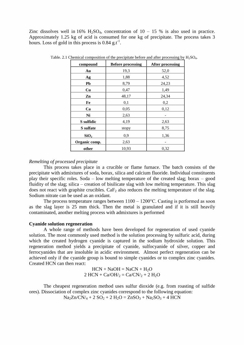
Zinc dissolves well in 16% H2SO4, concentration of 10 – 15 % is also used in practice.
Approximately 1.25 kg of acid is consumed for one kg of precipitate. The process takes 3
hours. Loss of gold in this process is 0.84 g.t-1
.
Remelting of processed precipitate
This process takes place in a crucible or flame furnace. The batch consists of the
precipitate with admixtures of soda, borax, silica and calcium fluoride. Individual constituents
play their specific roles. Soda – low melting temperature of the created slag; borax – good
fluidity of the slag; silica – creation of bisilicate slag with low melting temperature. This slag
does not react with graphite crucibles. CaF2 also reduces the melting temperature of the slag.
Sodium nitrate can be used as an oxidant.
The process temperature ranges between 1100 – 1200°C. Casting is performed as soon
as the slag layer is 25 mm thick. Then the metal is granulated and if it is still heavily
contaminated, another melting process with admixtures is performed
Cyanide solution regeneration
A whole range of methods have been developed for regeneration of used cyanide
solution. The most commonly used method is the solution processing by sulfuric acid, during
which the created hydrogen cyanide is captured in the sodium hydroxide solution. This
regeneration method yields a precipitate of cyanide, sulfocyanide of silver, copper and
ferrocyanides that are insoluble in acidic environment. Almost perfect regeneration can be
achieved only if the cyanide group is bound to simple cyanides or to complex zinc cyanides.
Created HCN can then react:
HCN + NaOH = NaCN + H2O
2 HCN + Ca/OH/2 = Ca/CN/2 + 2 H2O
The cheapest regeneration method uses sulfur dioxide (e.g. from roasting of sulfide
ores). Dissociation of complex zinc cyanides correspond to the following equation:
Na2Zn/CN/4 + 2 SO2 + 2 H2O = ZnSO3 + Na2SO3 + 4 HCN
Table. 2.1 Chemical composition of the precipitate before and after processing by H2SO4.
compound Before processing After processing
Au 19,3 52,0
Ag 1,88 4,52
Pb 8,79 24,23
Cu 0,47 1,49
Zn 48,17 24,34
Fe 0,1 0,2
Ca 0,05 0,12
Ni 2,63 -
S sulfidic 4,19 2,63
S sulfate stopy 8,75
SiO2 0,9 1,36
Organic comp. 2,63 -
other 10,93 0,32
Regeneration is performed on tower equipment, using a vaporizer to create HCN and an
absorber, where HCN is absorbed, e.g. using NaOH. It goes without saying that the apparatus
is hermetically sealed.
2.1.3.1 Production of gold from anode sludge after electrolysis of copper
During the production of copper from copper ores, which in most cases contain
precious metals, the gold is gradually concentrate in matte, black copper and after electrolysis
it moves to the anode sludge. This sludge can be processed by different methods – depending
on the chemical composition. The first step of all methods consists of separation of copper by
dissolution in diluted H2SO4 at a temperature of 70°C with air blowing.
Decoppered sludge is further processed in two stages. In the first stage Se and Te are
removed with the aim to increase the concentration of precious metals in the residues. The
next stage consists of oxidizing melting of the sludge with the aim to obtain an alloy of Ag +
Au (i.e. doré).
Majority of Se and Te is obtained by oxidizing roasting, sulfatizing roasting and soda
caking. The prepared Ag + Au alloy then proceeds to electrolytic refining.
2.1.4 Gold refining
Use of gold in technological practice requires a high-purity metal. Gold is refined
either by the electrolytic method or by selective precipitation of individual admixtures. The
most important role is played by electrolytic refining.
2.1.4.1 Electrolytic refining of gold
This technology offers a whole range of advantages in comparison with other
methods. This method can be used to prepare the purest metal, the process price is
economically acceptable and it can yield platinum metals as by-products. It was first used in
1908.
Solution of HCl and AuCl3 is used as electrolyte. Raw gold is used as anodes in this
process. Cathodes are used in the form of a mother sheet after electrolytic refining. After the
introduction of direct current, anodes are dissolved and gold is transformed to Au3+
. Part of
the admixtures enters the solution and part deposits at the bottom of the electrolyzer in the
form of anode sludge.
The following ions are contained in electrolyte at the same time:
AuCl3 = Au3+
+ 3 Cl-
HCl = H+ + Cl
-
H2O = H+ + OH
-
The following processes occur as the current is passing through the electrolyte:
Au3+
+ 3 e- = Au
This occurs on the cathode, admixtures and hydrogen are not released at the cathode due to
their potentials, which are low in comparison with gold (Au/Au3+
= 1.5 V).
Electrochemical oxidation of gold occurs at the anode:
Au – 3e- = Au
3+
Gold that enters the electrolytic refining contains the following admixtures: Cu, Pb, Ag, Pt, Pd
and others. The behaviour of these admixtures depends on their solubility in electrolyte,
potentials and other factors.
2.1.5 Application of gold
The largest amount of gold is used for the production of artistic and decoration
objects. Due to its low mechanical properties, gold needs to be used in form of alloys, most
often with silver. The content of gold in various alloys is stated in thousandths or carates.
Another application of gold consists of gold-plating of objects made of less noble
metals – mostly silver or copper. Gold can also be used in stomatology, as well as for special
equipment in chemical laboratories. Last but not least, this metal is used to produce special
contacts and in semi-conductor and space technology.
2.1.6 Gold alloys
Gold is most frequently alloyed with metals of the same group. In addition, the
following metals can also be used: Zn, Cd, Cr, Mn, Ni, Co, etc.
Au – Ag system
An addition of silver decreases the melting temperature of the alloy, whereas the
crystallization interval is narrow. Both elements form a binary diagram with perfect solubility
of both constituents in solid form. The colour changes and contains a tinge of green. Ag is the
most commonly used admixture when the alloy is used for minting, alternatively with copper
for jewellery.
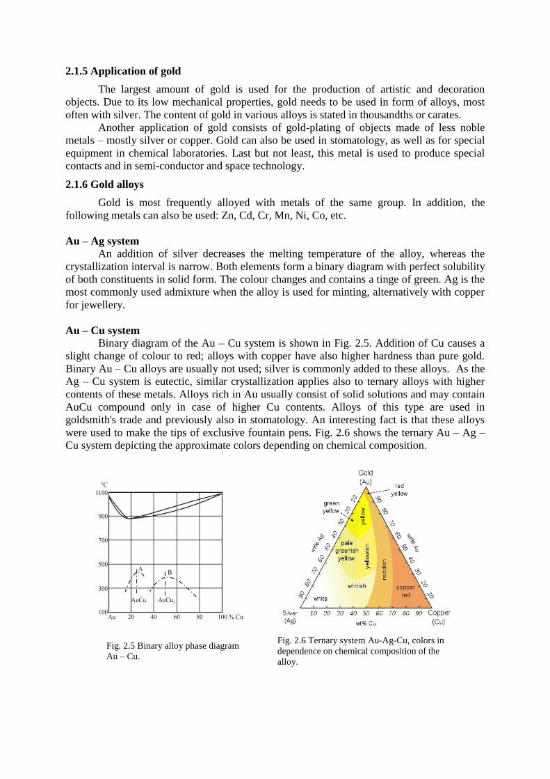
Au – Cu system
Binary diagram of the Au – Cu system is shown in Fig. 2.5. Addition of Cu causes a
slight change of colour to red; alloys with copper have also higher hardness than pure gold.
Binary Au – Cu alloys are usually not used; silver is commonly added to these alloys. As the
Ag – Cu system is eutectic, similar crystallization applies also to ternary alloys with higher
contents of these metals. Alloys rich in Au usually consist of solid solutions and may contain
AuCu compound only in case of higher Cu contents. Alloys of this type are used in
goldsmith's trade and previously also in stomatology. An interesting fact is that these alloys
were used to make the tips of exclusive fountain pens. Fig. 2.6 shows the ternary Au – Ag –
Cu system depicting the approximate colors depending on chemical composition.
Fig. 2.6 Ternary system Au-Ag-Cu, colors in
dependence on chemical composition of the
alloy.
Fig. 2.5 Binary alloy phase diagram
Au – Cu.

Au – Ni system
Alloys of this system have higher hardness and are therefore less malleable than other
alloys. Ni causes discoloration of gold to silver – in the past this method was used to produce
white gold. These alloys contained 7 – 15 % Ni. This process is no longer used and white
gold is produced from the Au – Pd system.
Au – Pd system
Similarly to Au – Ag, this system creates a wide range of solid solutions. The addition
of Pd causes a significant increase of the melting temperature of the alloy. Pd also causes
discoloration, the alloy is completely silvery white already at 15 % of Pd. Alloys have good
malleability and resistance to corrosion. They are applied in stomatology, as well as to
produce protection melting insert to small electric furnaces.
Au – Pt system
There is a wide range of crystallization in this system and that is why the composition
of the alloy during crystallization is considerably unbalanced. Two solid solutions begin to
separate in the solid state, which results in brittleness of medium-composition alloys. Only
alloys with up to 20 % of Pt are malleable. For binary diagram of this system see Fig. 2.7.
In terms of application, the alloys can be divided into the following groups:
alloys for jewellery,
dental alloys,
alloys for production of contacts,
alloys for special purposes.
2.2 Silver
Together with gold, silver is one of the first metals discovered by the people. In nature
it occurs in the metallic form in sediments or in minerals. Since silver is relatively rare and is
very soft, malleable and air-stable, it was used namely to produce various decorations. Only
later it was applied also in minting. Today, most of the silver is obtained as a by-product from
the production of lead, copper and zinc.
Fig. 2.7 Binary alloy phase diagram Au – Pt.
2.2.1 Silver properties
The melting temperature of silver is 960.5°C, boiling temperature is 2212°C. Its
specific weight is 10.5 g.cm-3
. It has the highest electrical and thermal conductivity of all
metals. Silver crystallizes similarly as gold in the KPC lattice. After gold, silver is the most
malleable metal. It is possible to create a film with a thickness of 0.002 mm.
Silver is air-stable and is not damaged in contact with other metals. It is resistant to weaker
oxidizing agents, as well as to most saline solutions. It dissolves in nitric acid and in hot
sulfuric acid.
2.2.2 Silver compounds
Almost all compounds are derived from monovalent silver. The general formula of
these compounds is AgX. Exceptionally, silver may be bivalent and very rarely trivalent.
Silver oxide
Ag2O is created by the following reaction:
Ag+ + OH
- = AgOH
2 AgOH = Ag2O + H2O
It is formed mostly by the addition of ions OH- to the solution of silver salts. This oxide
dissolves in aqueous ammonia solution.
Silver halides
This group includes silver fluoride, which is also its most soluble representative.
Least soluble is iodide. Fluoride may be prepared by dissolving Ag2O in HF. Silver chloride
AgCl is released from the solution containing ions Ag+ and Cl
- in the form of a white
precipitate. In nature it occurs as cerargyrite – this ore can be found in larger amounts only in
America. AgCl dissolves in concentrated HCI and in ammonia, while creating complex salts.
The sensitivity of AgCl to light also has an important practical application. It enables
its use in the area of analogue photography. Silver bromide is a similar substance. However, it
is more sensitive to light than chloride.
Silver nitrate
Silver nitrate is the most important compound from the technical point of view. It is
prepared by dissolution of elementary silver in HNO3. Silver nitrate dissolves well in water.
Silver sulfate
The melting temperature of Ag2SO4 is 660°C. It does not dissolve well in water.
Sulfate can be transformed to chloride when melted in hydrogen chloride environment:
Ag2SO4 + 2 HCl = 2 AgCl + H2SO4
Silver sulfide
Ag2S is released as a black precipitate when hydrogen sulfide is introduced to the
solution of silver salts. It is also created by the effect of sulfides or hydrogen sulfide on
elementary silver. It is the least soluble silver salt. In nature it occurs as double arsenic and
antimony sulfide.
Silver cyanide
AgCN – a white precipitate released from solutions of silver salts after CN- ions are
added. It is insoluble in water but dissolves well in alkaline cyanides, creating complex salts.
2.2.3 Production technology
Silver is a relatively common metal and its content it the Earth's crust is in the order of
10-5
%. In nature it occurs in pure form, as well as chemically bound. Pure silver almost
always contains admixtures of copper and gold.
The most common form of silver in the nature is the sulfide form and it usually
accompanies sulfides of other metals (Pb, Sb, As, Cu). It often constitutes a significant
admixture of galenite.
The most important minerals include:
Argentite – Ag2S. This is an important ore; its most significant deposits are located in
Mexico.
Pyrargyrite – Ag3SbS3.
Proustite– Ag3AsS3.
Tetraedrite – the silver content in this mineral is low (about 1 %); however, it occurs
in many copper and lead ores.
cerargyrite – AgCl. After it is transformed to sulfide, this mineral floats well,
cyanides and amalgamates well.
Argentite and tetraedrite have good floatation properties. Cyaniding of argentite may be
performed directly under specific circumstances, tetraedrite cannot be leached directly. Other
sulfides need to be processed before leaching.
Silver is produced by pyrometallurgic and hydrometallurgic processes.
Hydrometallurgic processes include amalgamation and cyaniding; pyrometallurgic processes
include mainly silver production as the by-product of copper and lead production. Nowadays
silver is mostly prepared pyrometallurgically.
2.2.3.1 Hydrometallurgic processes of silver extraction
As already stated above, this group of processes includes amalgamation and
cyaniding.
Amalgamation
This methods, just like in the production of gold, is based on the ability of silver to
form amalgams with mercury. Most suitable for amalgamation is AgCl. Sulfidic minerals
have poor solubility in mercury and therefore require chlorination. The yield of these process
was very low and that is why they needed to be improved - amalgamation was performed
simultaneously with grinding, amalgam was heated by water vapours, etc. This method is no
longer used today.
Cyaniding
The process is based on dissolving of pure silver and silver minerals in cyanide
solutions. Pure silver is dissolved in an alkaline cyanide solution in accordance with the
following reaction:
2 Ag + 4 KCN + H2O + ½ O2 = 2 K[Ag/CN/2] + 2 KOH
Dissolution of AgCl cerargyrite in alkaline cyanide occurs relatively fast in accordance with
the following reaction:
AgCl + 2 KCN = K[Ag/CN/2] +KCl
Cyaniding of silver ores is very similar to the process used for gold. However, the
cyanide solution concentration is higher in this case. Silver ores need to be ground to finer
particles, which is why their leaching is performed simultaneously with mixing. Percolation
leaching was used only exceptionally. During leaching it is necessary to aerate the mash.
Leaching takes tens of hours.
Silver from the cyanide solution is precipitated by zinc dust (aluminium or sodium
sulfide can also be used). Silver precipitation by aluminium occurs in accordance with the
following reaction:
Na[Ag/CN/2] + 2 NaOH + Al = 2 NaCN + NaAlO2 + Ag + H2
An important advantage of aluminium is the better regeneration of cyanide.
2.2.3.2 Pyrometallurgic production of silver from lead ores
Silver is obtained during the production of lead as a by-product, since lead ores
contain a significant amount of silver. That is why lead-processing plants usually process
concentrates, whereas the first step is usually agglomeration. During agglomeration of a
concentrate with granularity of 0.1, argentite is oxidized at a temperature of 650 °C.
Oxidizing roasting can be represented by the following equation:
Ag2S + O2 = 2 Ag + SO2
Oxidation of silver sulfide and formed silver then continues as follows:
2 Ag + 2 SO3 = Ag2SO4 + SO2
Ag2S + 4 SO3 = Ag2SO4 + 4 SO2
Silver sulfate is a stable compound, which begins to disassociate at a temperature of 850 °C
and ends at 1080 °C, while creating metallic silver:
2 Ag2SO4 = 4 Ag + 2 SO2 + 2 O2
Lead is an excellent collector of precious metals, which is why when melted in a shaft
furnace, 90 % of silver and 98 – 99 % of gold is transferred to raw lead. Raw lead can
therefore contain 10 – 15 g.t-1
Au and 1 – 5 kg.t-1
Ag. Historic methods of precious metal
extraction from lead included cupellation and patinazation. These methods are no longer used
today.
Parkerizing
Parkerizing is the most used method today. This method of silver extraction from lead
using zinc was implemented to practice in 1842. It is a highly progressive method of silver
extraction with minimum losses of the metal. This process is based on bounded mutual
solubility of lead and zinc and total insolubility of zinc and silver alloys at low temperatures
in zinc-saturated liquid lead.
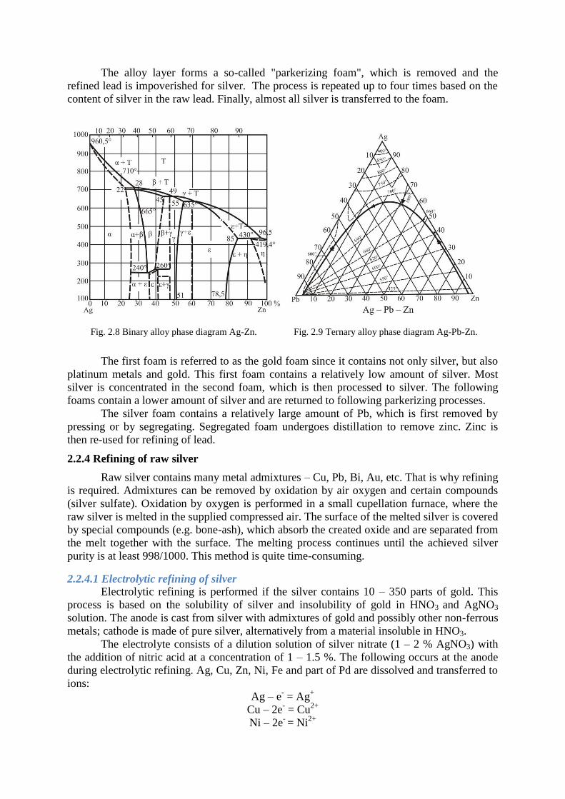
It is clear from the binary diagram of the Ag – Zn system (Fig. 2.8) that Zn forms
several inter-metallic compounds with silver. The composition of the created alloy depends on
the mutual ratio of silver and zinc in the melting and on the temperature. Two inter-metallic
compounds are formed during the refining of lead from silver using zinc: Ag2Zn3 with a
melting temperature of 665°C and Ag2Zn5 with a melting temperature of 636°C. The Ag2Zn3
compound dissolves in lead at a higher temperature; however, its solubility significantly
reduces with decreasing temperature and at 330°C it is practically insoluble in lead. Its
density is lower than lead and it creates a hard layer concentrating all silver contained in the
raw lead. This layer is removed mechanically together with a significant amount of lead.
However, not all lead is a mechanical admixture; part of it forms a ternary alloy with zinc and
silver with the content of Pb of approximately 2 – 5 %. The ternary system of Ag – Zn – Pb is
shown in Fig. 2.9.
The alloy layer forms a so-called "parkerizing foam", which is removed and the
refined lead is impoverished for silver. The process is repeated up to four times based on the
content of silver in the raw lead. Finally, almost all silver is transferred to the foam.
The first foam is referred to as the gold foam since it contains not only silver, but also
platinum metals and gold. This first foam contains a relatively low amount of silver. Most
silver is concentrated in the second foam, which is then processed to silver. The following
foams contain a lower amount of silver and are returned to following parkerizing processes.
The silver foam contains a relatively large amount of Pb, which is first removed by
pressing or by segregating. Segregated foam undergoes distillation to remove zinc. Zinc is
then re-used for refining of lead.
2.2.4 Refining of raw silver
Raw silver contains many metal admixtures – Cu, Pb, Bi, Au, etc. That is why refining
is required. Admixtures can be removed by oxidation by air oxygen and certain compounds
(silver sulfate). Oxidation by oxygen is performed in a small cupellation furnace, where the
raw silver is melted in the supplied compressed air. The surface of the melted silver is covered
by special compounds (e.g. bone-ash), which absorb the created oxide and are separated from
the melt together with the surface. The melting process continues until the achieved silver
purity is at least 998/1000. This method is quite time-consuming.
2.2.4.1 Electrolytic refining of silver
Electrolytic refining is performed if the silver contains 10 – 350 parts of gold. This
process is based on the solubility of silver and insolubility of gold in HNO3 and AgNO3
solution. The anode is cast from silver with admixtures of gold and possibly other non-ferrous
metals; cathode is made of pure silver, alternatively from a material insoluble in HNO3.
The electrolyte consists of a dilution solution of silver nitrate (1 – 2 % AgNO3) with
the addition of nitric acid at a concentration of 1 – 1.5 %. The following occurs at the anode
during electrolytic refining. Ag, Cu, Zn, Ni, Fe and part of Pd are dissolved and transferred to
ions:
Ag – e- = Ag
+
Cu – 2e- = Cu
2+
Ni – 2e- = Ni
2+
Fig. 2.8 Binary alloy phase diagram Ag-Zn. Fig. 2.9 Ternary alloy phase diagram Ag-Pb-Zn.
Silver is further released at the cathode and Ni, Fe and Zn remain in the solution. Cu and Pd
usually cause certain problems due to their increasing concentration in the solution. That is
why a cleaning of the solution should be included.
Au, Se and Te do not dissolve; after the anode material is dissolved, these materials
are released in their elementary form in the form of dust that gathers at the bottom of the
apparatus as the anode sludge.
Bi, Sb and PB are dissolved and enter the electrolyte. Pb is then precipitated to PbO2,
bismuth hydroxide and antimony. These products also do not dissolve and are transferred to
the anode sludge.
The cathode releases silver if the copper concentration in the solution does not exceed
150 g.l-1
. The obtained cathode silver has a coarse-grained crystalline structure and is
relatively brittle, which is why it needs to be periodically removed from the cathode. At the
same time, the cathode and anode areas may be separated. Purity of the cathode silver is 999.8
– 999.9/1000. Other products of the electrolysis are: anode sludge (approximately 28 % of the
anode weight), anode residues (approximately 15 %), spent electrolyte containing 20 g.l-1
Ag
and gases.
Cathode silver is then remelted in an electric furnace at a temperature of 1000°C. Se
and Te are oxidized during this process by leaving the melting rest for approximately 20
minutes and then adding wood coal in order to absorb excessive oxygen. After this operation
the silver is cast.
Spent electrolyte is processed by electrolysis with insoluble anodes (extraction
electrolysis) It is performed until the silver is completely extracted (yielding silver with a
purity of 800/1000). This is silver is used to produce anodes. Copper is removed from the
solution by cementation using Fe shavings. The next operation consists of processing of the
anode sludge.
2.2.5 Application of silver and silver alloys
Metallic silver is used namely for decorative and utility objects and it also plays an
important role in the chemical industry (reaction vessels, crucibles) and electrotechnics
(contacts, circuit breakers). In the past this metal was used in coin minting.
Ag – Cu system.
These are the oldest alloys ever. Cu significantly improves the mechanical properties,
which is why these alloys are used for minting of coins and for technical purposes. Cu reduces
the thermal and electrical conductivity.
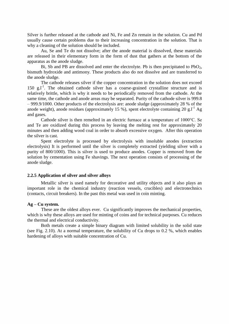
Both metals create a simple binary diagram with limited solubility in the solid state
(see Fig. 2.10). At a normal temperature, the solubility of Cu drops to 0.2 %, which enables
hardening of alloys with suitable concentration of Cu.
The Ag + 10 % Cu alloy - used in coin minting.
- in Czech Republic the content is determined to 959 ‰, 935‰, 900‰, 835‰, 800‰.
The Ag + Cu alloy – contact material – Ag95-Cu, Ag90-Cu, Ag80-Cu.
Ag - Zn system
An addition of Zn (approximately 1 %) improves the foundry properties and bonding
of dissolved oxygen, which prevents sputtering of the metal during casting. Zinc is often
included in silver solders.
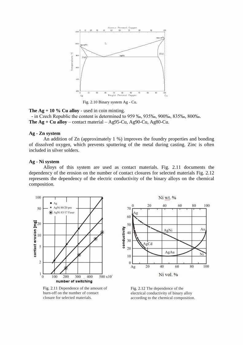
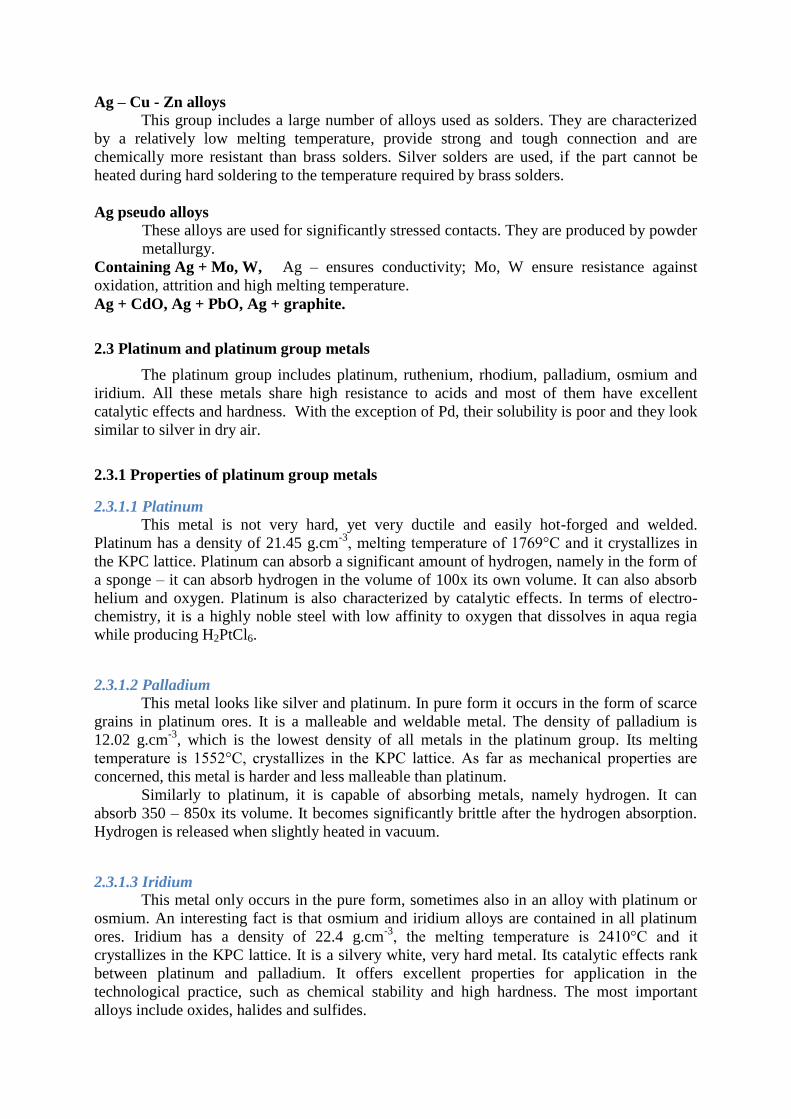
Ag - Ni system
Alloys of this system are used as contact materials. Fig. 2.11 documents the
dependency of the erosion on the number of contact closures for selected materials Fig. 2.12
represents the dependency of the electric conductivity of the binary alloys on the chemical
composition.
A g - C u p h ase d i ag r am .
Fig. 2.10 Binary system Ag - Cu.
Fig. 2.11 Dependence of the amount of
burn-off on the number of contact
closure for selected materials.
Fig. 2.12 The dependence of the
electrical conductivity of binary alloy
according to the chemical composition.
Ag – Cu - Zn alloys
This group includes a large number of alloys used as solders. They are characterized
by a relatively low melting temperature, provide strong and tough connection and are
chemically more resistant than brass solders. Silver solders are used, if the part cannot be
heated during hard soldering to the temperature required by brass solders.
Ag pseudo alloys
These alloys are used for significantly stressed contacts. They are produced by powder
metallurgy.
Containing Ag + Mo, W, Ag – ensures conductivity; Mo, W ensure resistance against
oxidation, attrition and high melting temperature.
Ag + CdO, Ag + PbO, Ag + graphite.
2.3 Platinum and platinum group metals
The platinum group includes platinum, ruthenium, rhodium, palladium, osmium and
iridium. All these metals share high resistance to acids and most of them have excellent
catalytic effects and hardness. With the exception of Pd, their solubility is poor and they look
similar to silver in dry air.
2.3.1 Properties of platinum group metals
2.3.1.1 Platinum
This metal is not very hard, yet very ductile and easily hot-forged and welded.
Platinum has a density of 21.45 g.cm-3
, melting temperature of 1769°C and it crystallizes in
the KPC lattice. Platinum can absorb a significant amount of hydrogen, namely in the form of
a sponge – it can absorb hydrogen in the volume of 100x its own volume. It can also absorb
helium and oxygen. Platinum is also characterized by catalytic effects. In terms of electro-
chemistry, it is a highly noble steel with low affinity to oxygen that dissolves in aqua regia
while producing H2PtCl6.
2.3.1.2 Palladium
This metal looks like silver and platinum. In pure form it occurs in the form of scarce
grains in platinum ores. It is a malleable and weldable metal. The density of palladium is
12.02 g.cm-3
, which is the lowest density of all metals in the platinum group. Its melting
temperature is 1552°C, crystallizes in the KPC lattice. As far as mechanical properties are
concerned, this metal is harder and less malleable than platinum.
Similarly to platinum, it is capable of absorbing metals, namely hydrogen. It can
absorb 350 – 850x its volume. It becomes significantly brittle after the hydrogen absorption.
Hydrogen is released when slightly heated in vacuum.
2.3.1.3 Iridium
This metal only occurs in the pure form, sometimes also in an alloy with platinum or
osmium. An interesting fact is that osmium and iridium alloys are contained in all platinum
ores. Iridium has a density of 22.4 g.cm-3
, the melting temperature is 2410°C and it
crystallizes in the KPC lattice. It is a silvery white, very hard metal. Its catalytic effects rank
between platinum and palladium. It offers excellent properties for application in the
technological practice, such as chemical stability and high hardness. The most important
alloys include oxides, halides and sulfides.
2.3.1.4 Rhodium
White, malleable metal. It occurs in platinum ores and certain gold-bearing sands. The
melting temperature of this metal is 1960 °C, the density is 12.44 g.cm-3
, crystallizes in the
KPC lattice. Melted Rh can dissolve up to 7 % of C, which is released during cooling in the
form of graphite. Just like other metals in this group, rhodium has excellent catalytic effects.
It can be used also in electro-technics as a contact material, as no oxide layers are created on it
(it maintains a very low resistance).
2.3.1.5 Osmium
This metal occurs in platinum ores in the form of an alloy with iridium. This alloy is
insoluble in aqua regia. The content of Os ranges between 17 – 80 %. This metal has a density
of 22.5 g.cm-3
, melting temperature of 3033°C, and the HTU lattice. Osmium is a blue-grey,
very hard and brittle metal. It was discovered in vapours of highly irritable osmic oxide,
which is produced during melting of residues of platinum minerals insoluble in aqua regia. It
has the best catalytic effects of the whole group of metals.
2.3.1.6 Ruthenium
This metal is the rarest metal from this group. It rarely occurs as the mineral laurite
RuS2. The density of ruthenium is 12.4 g.cm-3
, its melting temperature is 2250°C nad it has
the HTU lattice. It is a matte grey, very hard and brittle metal. It evaporates during arc
melting, as well as during high-temperature annealing (in the form of ruthenium dioxide). It
can absorb a relatively large amounts of oxygen or hydrogen. Just like other metals in this
group, it is characterized by catalytic effects.
2.3.2 Production technology of platinum metals.
Platinum occurs quite sporadically in the Earth's crust. Its content is the orders of 10-5
%. It often occurs in the form of an alloy with iron and chemical compounds with other
metals of the platinum group. The most important minerals include:
Poxylene – ferroplatinum, this mineral contains about 5 – 10 % of Fe and the highest
amount of platinum, i.e. 88 %.
Minerals associated with pyrrhotite, pentlandite and chalkopyrite – Sperilite PtAs2,
Cuprite PtS, Breggite /Pt, Pd, Ni/S and stibiopaladinite Pd3Sb.
Cuproplatinum – alloy with copper (5 – 13 % of Cu).
Nickelplatinum – approximately 3 % of Ni.
Nevyanskite and sysertskite – natural alloys of osmium and iridium.
Platinum grains are often covered by a thin layer of Fe oxides and are therefore
magnetic. Pure platinum in Cu – Ni ores occurs mostly in the form of breggite, cuperite or
sperilite. The most important sites of raw platinum metals are located in Russia, South Africa,
US, Canada and some other areas.
Raw materials used to produce platinum metals can be divided into the following
groups.
Platinum ores.
Non-ferrous metal ores containing platinum metals.
Wastes.
Due to the amount of target metals in the input raw materials, the platinum ores are
first concentrated. This is done by gravitation, floatation, amalgamation, chlorination and
other methods.
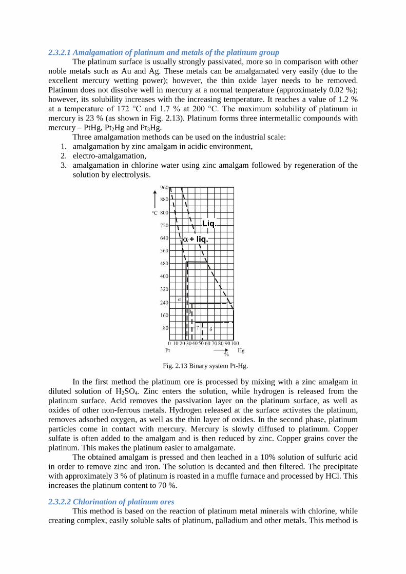
2.3.2.1 Amalgamation of platinum and metals of the platinum group
The platinum surface is usually strongly passivated, more so in comparison with other
noble metals such as Au and Ag. These metals can be amalgamated very easily (due to the
excellent mercury wetting power); however, the thin oxide layer needs to be removed.
Platinum does not dissolve well in mercury at a normal temperature (approximately 0.02 %);
however, its solubility increases with the increasing temperature. It reaches a value of 1.2 %
at a temperature of 172 °C and 1.7 % at 200 °C. The maximum solubility of platinum in
mercury is 23 % (as shown in Fig. 2.13). Platinum forms three intermetallic compounds with
mercury – PtHg, Pt2Hg and Pt3Hg.
Three amalgamation methods can be used on the industrial scale:
1. amalgamation by zinc amalgam in acidic environment,
2. electro-amalgamation,
3. amalgamation in chlorine water using zinc amalgam followed by regeneration of the
solution by electrolysis.
In the first method the platinum ore is processed by mixing with a zinc amalgam in
diluted solution of H2SO4. Zinc enters the solution, while hydrogen is released from the
platinum surface. Acid removes the passivation layer on the platinum surface, as well as
oxides of other non-ferrous metals. Hydrogen released at the surface activates the platinum,
removes adsorbed oxygen, as well as the thin layer of oxides. In the second phase, platinum
particles come in contact with mercury. Mercury is slowly diffused to platinum. Copper
sulfate is often added to the amalgam and is then reduced by zinc. Copper grains cover the
platinum. This makes the platinum easier to amalgamate.
The obtained amalgam is pressed and then leached in a 10% solution of sulfuric acid
in order to remove zinc and iron. The solution is decanted and then filtered. The precipitate
with approximately 3 % of platinum is roasted in a muffle furnace and processed by HCl. This
increases the platinum content to 70 %.
2.3.2.2 Chlorination of platinum ores
This method is based on the reaction of platinum metal minerals with chlorine, while
creating complex, easily soluble salts of platinum, palladium and other metals. This method is
Fig. 2.13 Binary system Pt-Hg.

used to process platinum ores in South Africa. Ores contain approximately the same amount
of platinum and palladium in sulfide form.
Ground ore is first floated and then obtained concentrate undergoes chlorinating
roasting. The concentrate contains approximately 250 – 340 g.t-1
of the target metals. The
process takes place at a temperature of 550 – 600°C in a compound with NaCl for 4 hours.
The process can be described by the following equation:
Me + 2 Cl2 + 2 NaCl = Na2[PtCl6]
where Me represents Pt, Pd, Ir.
After chlorination the material is processed by HCl solution. Pt, Pd and Ir enter the
solution in the form of complex alkaline chlorides accompanied by copper and nickel (in the
form of simple chlorides). For further processing of the solution see.
2.3.2.3 Affination of platinum metals
The term affination refers to mutual separation of individual metals of the platinum
group. Affination processes of platinum metals are done using concentrates prepared by the
gravitation treatment, precipitates after chlorination of platinum concentrates, alloys from
amalgamation, anode sludge from Ni and Cu electrolysis, residues after electrolytic
production of gold, wastes of selected products, etc.
There are more processing variants for individual materials due to their varying
composition. After the gravitation treatment, platinum contains 80 % of Pt, 3 – 6 % of Ir,
below 1 % of Rh. It also contains Pd and a significant amount of Fe, up to 18 %. Pt
concentrates from processing of anode sludge from the production of Cu and Ni contain
usually about 30 – 50 % of Pt metals with high content of Pd.
The first step of affination of gravitation concentrates consists of dissolution of the
material in aqua regia while stirring the material. The reaction of metals with the acid can be
represented as follows:
3 HCl + HNO3 = Cl2 + NOCl + H2O
Pt + 2 Cl2 = PtCl4
Pt + 4 NOCl = PtCl4 + 4 NO
Chlorides of platinum metals created by the reaction with aqua regia further react with HCL
and create complex acids:
PtCl4 + 2 HCl = H2[PtCl6]
PdCl4 + 2 HCl = H2[PdCl6]
IrCl4 + 2 HCl = H2[IrCl6]
RhCl3 + 2 HCl = H3[RhCl6]
RuCl3 + 2 HCl = H3[RuCl6]
Osmium is oxidized and creates osmium tetraoxide, which remains in the insoluble
residues. HNO3 is completely removed from solutions containing complex acids of platinum
metals with the addition of HCl. This is followed by precipitation of platinum by ammonium
chloride in the form of ammonium hexachloroplatinate. Pd and Ir are precipitated together
with platinum; however, the valence of these elements needs to be lowered. Reduction of Pd
and Ir can be carried out using various reducing agents. Most commonly the solution is
heated, evaporated and then sulfuric acid, oxalic acid or alcohol are added. At a temperature
of 140 °C, after the addition of H2SO4 for pH adjustment, the reaction occurs in accordance
with the following equation:
IrCl4 = IrCl3 + ½ Cl2
IrCl3 + 3 HCl = 3 H[IrCl6]
PdCl4 = PdCl2 + Cl2
PdCl2 + 2 HCl = H2[PdCl4]
After reduction of palladium and iridium, platinum is precipitated by ammonia chloride in
accordance with the following reaction:
H2[PtCl6] + 2 NH4Cl = /NH4/2[PtCl6] + 2 HCl
The precipitate of ammonium hexachloroplatine is filtered, washed by HCl in order to remove
ammonium chloride, dried and annealed at a temperature of 600 °C and then at temperature of
1100 – 1200°C, it is dissociated in accordance with the following equation:
3 /NH4/2[PtCl6] = 3 Pt + 16 HCl + 2 NH4Cl + 2 N2
The produced platinum sponge is melted in an induction furnace. The yielded platinum is
referred to as the first grade platinum and it contains 99.8 % Pt, up to 0.1 % Ir and other
metals. Chemically pure platinum is obtained by repeated dissolution and precipitation. Other
metals in this group can be prepared by a whole range of other complex processes.
2.3.3 Application of platinum metals
Pure platinum has whole range of applications in the production of resistance
thermocouples, as well as in the field of electro technics as contact materials. This field
utilizes the fact that this metal is not covered by a thin layer of oxides, which ensures low
resistance of the contact. Platinum can also be used in chemical industry, including high-
pressure applications, thanks to its excellent corrosion resistance.
Palladium is often used as a substitution of platinum due to its lower price and lower
density. This metal can also be used as contact material. Other application options include
catalyzer. It can also be used as hydrogen absorber.
Rhodium can be used in the field of coating of other metal materials thanks to its high
gloss.
Iridium application consists of platinum alloying to increase the strength
characteristics. In addition, it is used in chemical industry as the material for crucibles for
high temperatures.
Osmium is used almost exclusively to prepare alloys (with approximately 80% content
of Os and further containing Ru and other metals of this group) with high hardness.
Ruthenium is used as the alloying element to palladium and platinum to increase their
mechanical properties. At the same time, this metal may be used as catalyzer.
2.3.4 Alloys
2.3.4.1 Pt alloys
Thermocouple:
0-1500°C – Pt-Pt90Rh10
1400-1700°C – Pt70Rh30-Pt94Rh6
Resistance:
Pt + 10-20%Rh
Pt + 40%Rh – temperatures 1550 – 1800°C
For production of contacts:
The surface is not coated by a layer of oxides, they are used for small current loads;
for higher loads Pt + Ir (10-25%) are used.
Production of glass fibres or artificial fibres: (jets Pt+10Rh)
Jewellery:
Pure Pt
Pt + 5%Ir, Pt + 4.5%Pd
2.3.4.2 Pd alloys
For production of contacts: Pd + 10-30% Ag
Pd + 40% Cu
Pd + 4.5% Ru
Pd + Ni, Co - exceptionally
Solders These alloys contain a relatively low content of Pd, yet they significantly affect the
solder properties – the solders are referred to as palladium solders. Alloys with Ag, Cu,
sometimes Ni and Mn.
At the end of each chapter you will find a list of literature used to prepare this study material.
The list of publications may also include literature for further individual study.
Summary of terms in this chapter (subchapter)
Cyanide process
Amalgamation
Affination
Parkerizing
Questions to the covered material
Briefly describe the production technology of gold by the cyanide process.
Why is the so-called protective base used in the cyanide process?
What other gold production technologies can you name?
Describe the technology of silver production as a by-product of the production of
heavy non-ferrous metals.
Name the basic Ag alloys.
Briefly describe the technology of platinum preparation.
3. Refractory metals
Time to study: 10 hours
Aim After studying this section the student should be able to:
Characterize the technologies of refractory metal preparation.
Select suitable material for application in technological practice.
Lecture
3.1 Tungsten
3.1.1 Tungsten properties
Tungsten has the highest melting temperature of all metals – 3422 °C; at the same time
it has the lowest pressure of vapours. The boiling temperature of tungsten is also very high –
5660 °C. This metal is highly resistant to corrosion and offers high strength properties. The
density of tungsten is 19.1 g.cm-3
, and it crystallizes in the KSC lattice. The thermal
conductivity of this metal is approximately half the thermal conductivity of Cu but is higher
than conductivity of Ni or Fe
Powder tungsten is grey, metallic tungsten is white and glossy. It oxidizes when
heated. It is acid-stable. The compact metal reacts with aqua regia and nitric acid only on the
surface; it slowly dissolves in the HNO3 + HF compound. It is also affected by molten salts
and other alkaline melts.
3.1.2 Tungsten compounds
Tungsten creates a whole range of compounds. The most important compounds
include tungstates, tungstic acid and tungsten trioxide.
Tungsten trioxide WO3
Yellow tungsten trioxide is produced during oxidation of the metal of tungsten
compounds by air oxygen. This oxide has a melting temperature of 1473 °C and evaporates at
1750 °C. It is insoluble in water; it dissolves in alkaline hydrate oxides while creating
tungstates and tungstic acid salts. This oxide can be prepared from acid by annealing;
however, it cannot be transformed to acid by water.
Tungstic acid H2WO4
It is released from hot tungstate solutions after strong acids are added. It has a yellow
color and is insoluble in most acids and in water.
Sodium tungstate Na2WO4
This compound is created by melting tungsten compounds contained in ores together
with sodium. This compound plays an important role in the preparation of tungsten
compounds and of metallic tungsten. It dissolves well in water.
3.1.3 Tungsten production technology
This metal does not occur in nature in pure form. It usually occurs in the form of oxide
bound to Fe, Mn and Ca oxides, less frequently to Pb and Cu oxides. There are about 15
tungsten minerals; however, the most important minerals for industry are wolframite and
scheelite.
Wolframite (Fe, Mn)WO4 is an isomorphic compound of Fe and Mn tungstates.
Individual pure minerals, i.e. ferberite and hübnerite, occur only scarcely. Its density is 7.1 –
7.9 g.cm-3
and it is weakly magnetic.
Scheelite CaWO4 has a density of 5.9 – 6.1 g.cm-3
, and is not magnetic.
Tungsten ores are usually poor and contain no more than 0.5 – 2 % of WO3. That is
why these ores need to be processed. The processing of tungsten ores includes gravitation,
floatation, electromagnetic and electrostatic methods. These processing methods yield a
concentrate containing 60 – 70 % of WO3. Mostly wolframite and scheelite concentrates are
prepared.
Processing of tungsten concentrates consists of three stages: a) concentrate
dissociation, b) obtaining technical tungstic acid, c) cleaning of the technical tungstic acid and
obtaining clean products with the required physical properties. The industrial methods of
tungsten concentrate dissociation can be divided into alkaline and acidic.
Wolframite concentrates are dissociated by caking with soda, leaching by NaOH
aqueous solution or acid leaching. Scheelite concentrates are also caked with soda or leached
in sodium aqueous solution. Another option is pressurized acid leaching. The following
sections briefly describe two commonly used methods.
3.1.3.1 Caking with soda
This is the most widespread method. The process takes place at a temperature of 800 –
900°C, whereas the wolframite reacts with soda in the presence of air in accordance with the
following reactions:
2 FeWO4 + Na2CO3 + ½ O2 = 2 Na2WO4 + Fe2O3 + 2 CO2
3 MnWO4 + 3 Na2CO3 + ½ O2 = 3 Na2WO4 + Mn3O4 + 3 CO2
Caking of wolframite with soda yields a product that contains sodium tungstate, ferric oxide,
manganese oxide and other compounds. The dissociation yield usually ranges between 98 –
99.5 %. In practice, this process can be realized continually.
3.1.3.2 Dissociation of wolframite concentrate by solution of sodium hydroxide
This method is also used very frequently. It is based on the reaction of wolframite with
concentrate solution of NaOH, while creating sodium tungstate. This process can be described
by the following reaction:
FeWO4 + 2 NaOH = Na2WO4 +Fe(OH)2
MnWO4 + 2 NaOH = Na2WO4 +Mn(OH)2
This method has a whole range of advantages in comparison with baking: it does not
require furnace, as the reaction takes place at a low temperature. The disadvantage of this
method consists in the requirement of fine grinding of the material.
3.1.3.3 Cleaning of sodium tungstate solutions
The solution of sodium tungstate is prepared by one of the described methods and it
usually contains a certain amount of soluble salts, which could contaminate the tungstic acid
obtained in the following operation. The solution needs to be cleaned of silicon, phosphorus,
arsenic and molybdenum. Similar methods are used to clean the solution of sodium
molybdate.
Removal of molybdenum is based on a reaction, during which molybdenum
precipitates in the form of MoS2. This method is based on the difference of solubility of
molybdenum sulfosalts and of tungsten, which are created during the passing of hydrogen
sulfide, when alkaline sulfides are added to the solution containing tungstate and sodium
molybdate. After the solution is acidified, sulfosalts are dissociated, while creating
precipitates of molybdenum and tungsten sulfides. When slightly alkaline sulfide is continued
to be added, only molybdenum sulfosalts are created and after acidification, molybdenum is
precipitated in the form of MoS2. This method can be described by three reactions:
Na2MoO4 + 4 Na2S + 4 H2O = Na2MoS4 + 8 NaOH
Na2MoS4 + 2 HCl = MoS3 + 2 NaCl + H2S
HCl acid is added to the solution (in the presence of congo red indicator), while the solution is
being heated. This is followed by perfect precipitation of MoS2, which brings about 1 – 2 %
of tungsten to the precipitate.
3.1.3.4 Obtaining of tungsten compounds
Cleaned solutions of sodium tungstate can be used to obtain tungsten compounds as
described below.
1. Direct precipitation of technical tungstic acid.
2. Precipitation of calcium tungstate, which is further processed by acid to technical
tungstic acid.
3. Crystallization of sodium tungstate or paratungstate.
Precipitation of technical tungstic acid.
The precipitation is preformed directly by processing the sodium tungstate solution
using HCl, HNO3 or H2SO4 in accordance with the following reaction:
Na2WO4 + 2 HCl = H2WO4 + 2 NaCl
24 – 25 % of HCl with a small addition of HNO3 (0.5 – 2 %) is used most frequently.
Precipitation is carried out in a ceramic or steel vessel. HCl is heated to 80 °C and a heated
solution sodium tungstate is then slowly added. The tungstic acid precipitate formed during
this process is washed by water and then by hot water acidified by HCl. This is followed by
filtration, centrifuge and drying The process effectiveness is usually 98 – 99 %.
Cleaning of technical tungstic acid
The prepared technical H2WO4 contains approximately 3 % of admixtures. These
include namely Na, Ca, Fe salts, H2MoO4 and other compounds. Cleaning of H2WO4 is
usually performed using the ammoniac method. It dissolves well in ammonia, while creating a
solution of ammonium tungstate and most of the admixtures remain in the precipitate.
Precipitateis separated and tungsten is precipitated from the ammoniac solution in the form
tungstic acid or ammonium paratungstate.
3.1.3.5 Preparation of tungsten oxide
Annealing of tungstic acid or ammonium paratungstate yields tungsten oxide in
accordance with the following reaction:
H2WO4 = WO3 + H2O
5 /NH4/2O.12WO3.11H2O = 12 WO3 + 10 NH3 + 16 H2O
The first reaction occurs at 500 °C, the second one above 250 °C. Tungsten oxide intended for
preparation of metallic tungsten must have the given chemical composition and defined size
of particles. In practice, these compounds are calcined in an electric muffle furnace at
temperatures of 600 – 800°C depending on the required particle size of the produced oxide.
The vapor tension of tungsten oxide is significantly high already at temperatures over 800 °C,
which leads to its losses.
3.1.3.6 Preparation of metallic tungsten
The production of a compact metal uses metallic powder as the basis. The powder is
obtained by reduction of tungsten compounds, e.g. by hydrogen, at relatively low temperature
of 800 – 1200°C. The requirements on properties of the powder are highest if the powder is
intended for preparation of malleable tungsten. The production of tungsten carbides may use
less pure powders.
Tungsten compounds may be reduced by hydrogen, carbon, aluminium, silicon and
sodium. The reduction of WO3 by carbon and hydrogen has the highest practical importance.
The purest metallic tungsten is prepared by reduction by hydrogen.
WO3 reduction by hydrogen
This process may be described by the following summary equation:
WO3 + 3 H2 ↔ W + 3 H2O
Research has shown that the reduction consists of several stages:
10 WO3 + H2 ↔ W10O29 + H2O
2 W10O29 + 3 H2 ↔ 5 W4O11 + 3 H2O
W4O11 + 3 H2 ↔ 4 WO2 + 3 H2O
WO2 + 2 H2 ↔ W + 2 H2O
In practice, this process is performed in a tube furnace. Continual or discontinuous
method may be used. The used hydrogen must be completely free of all admixtures, such as
oxygen and carbon dioxide. The reduction consists of two stages; the first one occurs at 700
°C, while tungsten dioxide is produced. Tungsten dioxide is then reduced at a higher
temperature. This process is suitable for obtaining powder with the desired granulometry.
Sublimation of WO3 begins at 850°C, W4O11 at 900°C and WO2 at 1050°C. Particles of
metallic tungsten increase in size during the sublimation of oxides. Higher temperature leads
to creation of coarser particles.
Reduction of WO3 by carbon
This process is used if both tungsten powder and tungsten carbide need to be
produced. Tungsten carbides W2C and WC are produced at a temperature exceeding 900 °C.
The process can be represented by the following equation:
WO3 + 3 C = W + 3 CO
The reduction is not performed directly by carbon but using CO, which is produced by the
Boudouard reaction:
WO3 + 3 CO = W + 3 CO2
CO2 + C = 2 CO
Similarly as in WO3 reduction by hydrogen, the process consists of several stages.
4 WO3 + CO ↔ W4O11
W4O11 + 3 CO ↔ 4 WO2 + 3 CO2
WO2 + 2 CO ↔ W + 2 CO
In practice, the reduction is performed by carbon materials, such as coke, soot with a
small content of ash. Tube rotation or crucible furnace is used.
3.1.3.7 Preparation of compact tungsten
High melting temperature of this metal represents a certain difficulty for melting and
casting. The basic preparation method for compact metal is powder metallurgy. This method
consists of the following basic processes:
1. Powder pressing.
2. Caking of mouldings.
3. Mechanical processing.
The aim of pressing is to transform the shapeless powder to an object with a certain
shape. Pressing may be performed in steel matrices. The mouldings are caked in two stages.
The first stage, which occurs at a temperature of 1150 – 1300°C, is referred to as low-
temperature caking. The second stage, with a temperature of 3000 °C, is called high-
temperature caking. In this way it is possible to obtain metal with satisfactory porosity and
structure, which is suitable especially for the following plastic deformation. Caking is usually
carried out in a hydrogen atmosphere. The obtained semi-finished products may be hot-forged
or hot-rolled.
3.1.4 Application of tungsten and tungsten alloys
The first significant application of this metal was the production light bulb fibres.
Another important field of application consists of alloying of HHS (High Speed Steel). These
alloying elements result in high hardness of the material and short-time resistance up to a
temperature of approximately 600 °C. This hardness is caused by the presence of very hard
carbidic phases.
In addition, this metal may be used for production of thermocouples and heating
resistors. Tungsten may by applied also in the preparation of alloys for contacts (10 – 40 %
Cu, 20 – 40 % Ag). Tungsten is often contained in special fire-resistant and corrosion-
resistant steels. Here it is combined with chromium, nickel and cobalt.
Another important application consists of the production of sintered carbides.
3.2 Molybdenum
3.2.1 Molybdenum properties
Compact molybdenum has a silver-grey color and is glossy. In powder form its color
is darker grey. It is a relatively hard metal; it can be polished and at higher temperatures also
forged. The melting temperature of molybdenum is 2610 °C, its density is 10.2 g.cm-3
. It
crystallizes in the KSC system.
Mechanical properties of this metal depend namely on the preceding thermal and
mechanical processing. At a normal temperature, it is air-stable; when annealed, it is quickly
covered by a layer of MoO3. Its absorption of hydrogen is low and it releases hydrogen
already at 300 °C. It forms carbides with carbon.
This metal practically does not react with diluted acids or with concentrated HCl. It
does, however, react with concentrated HNO3, hot H2SO4 and more strongly with aqua regia.
Molybdenum is practically insoluble in alkaline hydroxides. It forms compounds on multiple
oxidation levels. In addition to MoS2, it occurs in hexavalent form in compounds that are
important for the technological practice.
3.2.2 Compounds
Molybdenum forms a whole range of compounds. The most important compounds
include oxides, molybdic acid, molybdates and sulfides.
Oxides
The most stable oxide is MoO3, which is produced by molybdenum oxidation by air
oxygen. It is a very fine white powder with a melting temperature of 791°C, which sublimates
at temperatures right below the melting temperature. Annealed MoO3 is soluble in water. It is
dissolved in HF, in concentrated H2SO4, alkaline hydroxides and aqueous ammonium solution
while creating molybdates.
Other oxides include MoO2 and Mo2O5.
Molybdenic acid
After standing for a longer period of time, molybdenic solutions release molybdenic
acid, a yellow crystallic precipitate with low solubility in water. Its chemical composition is
H2MoO4.H2O. When slightly heated, it is transformed to the water-free form of H2MoO4.
Ammonium molybdate
Ammonium molybdate (NH4)2MoO4 can be prepared by dissolution of MoO3 in
ammonia. Ammonium paramolybdate 3 (NH4)2O.7MoO3.4H2O crystallizes from ammonium
solutions. It is air-stable and starts to dissociate at 151 °C. Reducing agents (SO2, H2S, etc.)
affect molybdenic acid or acidified molybdenum solution and create dark, intensive coloring
of the solution – so-called molybdenum blue.
Sulfides
Molybdenum creates two sulfides. MoS3 is released by the effect of H2S on acidified
molybdenum solutions. It creates a brownish precipitate, easily soluble e.g. in aqua regia.
MoS2 occurs in nature in the form of the mineral molybdenite. It can also be prepared
artificially. In air it quickly reacts with oxygen, while producing MoO3.
3.2.3 Production technology of molybdenum
Molybdenum is not a very common element, its mean content in the Earth's crust is in
orders of 1.10-3
%. There is a large number of minerals, the most important of which are
molybdenite, povelite, molybdite and wulfenite.
Molybdenite MoS2 - the most important mineral, most widespread in the industrial
scale. This mineral is used to prepare the largest amount of molybdenum. It is a soft mineral
with metallic gloss and a density of 4.7 – 4.8 g.cm-3
. It occurs for instance in silica dikes
together with scheelite, wolframite, cassiterite, pyrite, etc. Molybdenite usually contains 4 –
200 g.t-1
of rhenium.
Povelite CaMoO4 – secondary mineral created by oxidation of molybdenite. It is
white to grey with a dark green shade. Its density is 4.45 – 4.52. It is isomorphic with
scheelite, which is why it often contains tungsten.
Molybdenum ores are poor, which is why they need to be treated and concentrated
before processing. This is done almost exclusively using the floatation method. Molybdenite
is one of the easily floatable minerals.
Molybdenite concentrates constitute the basic raw material for production of
ferromolybdenum and compounds that are used for the production of molybdenum oxide and
sodium paramolybdate. Pure compounds are prepared either pyrometallurgically or
hydrometallurgically – processing of the calcinated ore in solution of ammonia, soda, sodium
hydroxide.
3.2.3.1 Oxidation roasting of molybdenite concentrate
Further processing of concentrates would not be possible without oxidation roasting.
The aim of this processing is complete or partial removal of sulfur and transformation of
sulfides to oxides. The basic reaction may be represented as follows:
MoS2 + 3 ½ O2 = MoO3 + SO2 + 1114,5 kJ
Molybdenite is oxidized by air at a temperature of 450 – 500°C. All sulfides of other
accompanying elements are transformed to oxides or sulfates. Certain sulfates, such iron
sulfate, are again dissociated to oxides at increased temperature. The produced molybdenum
oxide then reacts with oxides of accompanying elements, while producing molybdates. We
may use the following example:
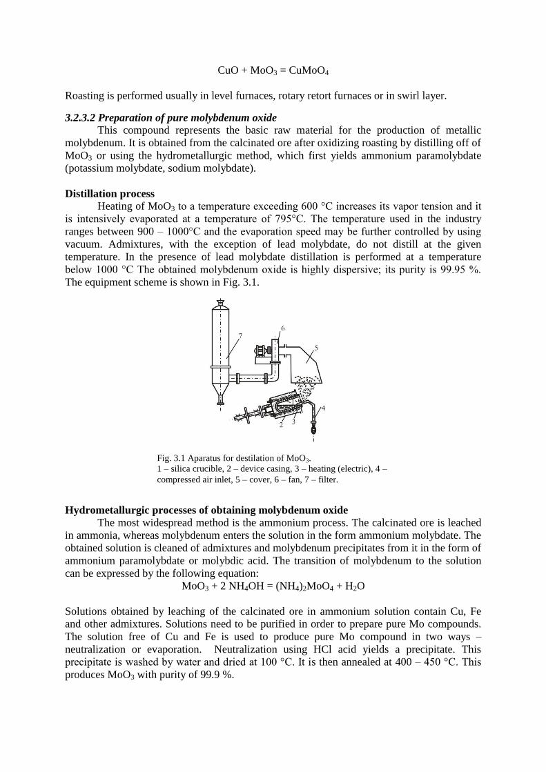
CuO + MoO3 = CuMoO4
Roasting is performed usually in level furnaces, rotary retort furnaces or in swirl layer.
3.2.3.2 Preparation of pure molybdenum oxide
This compound represents the basic raw material for the production of metallic
molybdenum. It is obtained from the calcinated ore after oxidizing roasting by distilling off of
MoO3 or using the hydrometallurgic method, which first yields ammonium paramolybdate
(potassium molybdate, sodium molybdate).
Distillation process
Heating of MoO3 to a temperature exceeding 600 °C increases its vapor tension and it
is intensively evaporated at a temperature of 795°C. The temperature used in the industry
ranges between 900 – 1000°C and the evaporation speed may be further controlled by using
vacuum. Admixtures, with the exception of lead molybdate, do not distill at the given
temperature. In the presence of lead molybdate distillation is performed at a temperature
below 1000 °C The obtained molybdenum oxide is highly dispersive; its purity is 99.95 %.
The equipment scheme is shown in Fig. 3.1.
Hydrometallurgic processes of obtaining molybdenum oxide
The most widespread method is the ammonium process. The calcinated ore is leached
in ammonia, whereas molybdenum enters the solution in the form ammonium molybdate. The
obtained solution is cleaned of admixtures and molybdenum precipitates from it in the form of
ammonium paramolybdate or molybdic acid. The transition of molybdenum to the solution
can be expressed by the following equation:
MoO3 + 2 NH4OH = (NH4)2MoO4 + H2O
Solutions obtained by leaching of the calcinated ore in ammonium solution contain Cu, Fe
and other admixtures. Solutions need to be purified in order to prepare pure Mo compounds.
The solution free of Cu and Fe is used to produce pure Mo compound in two ways –
neutralization or evaporation. Neutralization using HCl acid yields a precipitate. This
precipitate is washed by water and dried at 100 °C. It is then annealed at 400 – 450 °C. This
produces MoO3 with purity of 99.9 %.
Fig. 3.1 Aparatus for destilation of MoO3.
1 – silica crucible, 2 – device casing, 3 – heating (electric), 4 –
compressed air inlet, 5 – cover, 6 – fan, 7 – filter.
3.2.3.3 Production of metallic molybdenum
Pure molybdenum compounds may be reduced using C, Na, K, Al, etc. All these
methods cause contamination of the produced molybdenum. The purest molybdenum is
produced by reduction of MoO3 by hydrogen. The process consists of three stages and can be
represented as follows:
4 MoO3 + H2 ↔ Mo4O11 + H2O
Mo4O11 + 3 H2 ↔ 4 MoO2 + 3 H2O
MoO2 + 2 H2 ↔ Mo + 2 H2O
The reduction is performed in a horizontal furnace made of fire-proof steel, with a
nickel boat filled with molybdenum oxide (alternatively by ammonium paramolybdate). The
boat moves in the opposite direction of the supplied hydrogen. The hydrogen excess is three
times the stochiometric amount. The reduced molybdenum powder should be pure and at the
same time it should be have uniform granulometry.
3.2.3.4 Production of compact molybdenum
High melting temperature of molybdenum represents an obstacle during melting and
casting of this iron. There are two technologies for the preparation of malleable material –
powder metallurgy and melting and casting.
Powder metallurgy
This methods is based on the following processes: a) pressing of molybdenum powder,
b) baking of mouldings, c) mechanical processing. The powder density of the input
molybdenum powder is 2.2 – 2.8 g.cm-3
, the used pressure is 300 MPa. Mouldings prepared
by this method have a porosity of about 40 %. The material volume is reduced 3 – 4x.
Pressed Mo briquettes are sintered in two phases. The first stage, which occurs at a
temperature of 1200 °C, is referred to as low-temperature caking. The second stage, referred
to as high-temperature caking, occurs at temperatures of 2200 – 2400°C. This method yields
metal with minimum porosity. Molybdenum briquettes are brittle and break down during cold
deformation. However, after heating, the mouldings may be rolled or forged.
Melting and casting
This technology is performed in an electric arc furnace. Copper, water-cooled ladle is
used as the fire-proof material.
3.2.4 Application of molybdenum and molybdenum alloys
Molybdenum in form of a wire or sheet may be used as a heating element in laboratory
and industrial furnaces. In this case, the operating temperature may be increased up to
1700°C. Mo may be used to prepare tools for processing and hot-working of metals.
Other possible applications include production of special steels, namely for fire arms,
armour plates, etc. A small addition of molybdenum increases the strength and toughness of
steel. It is used together with vanadium, chromium, nickel and cobalt for production of high-
speed steels. Furthermore, it may be used for preparation of magnetic steels and alloys
resistant to corrosion in acidic environment. In these fields it is used mostly in the form of
ferromolybdenum.
An important field of application that needs to be mentioned is the chemical industry,
where molybdenum is used due to its high corrosion resistance for the production of
armatures, mixers, etc.

3.3 Titanium
3.3.1 Titanium properties
Titanium belongs to the group of refractory metals. The most important characteristics
of this metal include its low density, very good strength properties, relatively easy workability
and excellent corrosion resistance. It constitutes a very good alloying elements; most metals
form solid solutions with titanium. It has a melting temperature of 1670°C, density of 4.54
g.cm-3
. Titanium is a polymorphic metal. In a temperature range of 25 – 882°C, it has the
HTU structure; above a temperature of 882°C, it has the KSC structure.
In compact state it resembles steel. It is air-stable at low temperatures. At increased
temperatures it reacts with oxygen. Its solubility in acids is worse than that of iron. In HCl it
dissolves only after heating; hot HNO3 also attacks this metal. Titanium dissolves best in HF.
The addition of interstitial impurities (oxygen, carbon, nitrogen) significantly increases its
hardness and reduces ductility, see Fig. 3.2.
3.3.2 Compounds
Titanium in compounds occurs mostly in the tetravalent form. The most important
alloys include oxides, sulfates, compounds with halides, carbides and nitrides.
Oxides
Titanium dioxide – TiO2 occurs in nature as the mineral rutile. TiO2 begins to melt at
1800°C, at higher temperatures it transforms to Ti2O3. TiO2 dissolves slowly only in hot
H2SO4. This oxide may be obtained by heating a mixture of titanium of titanium dioxide.
Halide compounds
Titanium tetrachloride – TiCl4 may be prepared by the reaction of chlorine with heated
titanium, TiC, alloy of Ti – Al or a mixture of titanium dioxide with coal (coke). Its melting
temperature is 136.5°C, and it solidifies at -23°C. It is an important compound used in the
preparation process of metallic titanium.
Titanium tetraiodide – TiI4 may be prepared by reaction of TiCl4 with HI. It has a
melting temperature of 150°C and a boiling temperature of 365°C. This compound plays an
important role in titanium refining.
Titanium sulfates
Evaporation of titanic acid or reaction of titanium dioxide with concentrated sulfuric
acid produces titanium(IV) oxysulfate TiOSO4. It is a white powder soluble in water.
Fig. 3.2 Influence on N, C, O on mechanical properties of titanium
Titanium carbide
TiC is prepared by heating of fine titanium powder with soot in hydrogen atmosphere
at a temperature of 2000 °C. It is more resistant to acids than titanium. It is also an extremely
hard material. Its melting temperature is 3450 °C.
3.3.3 Production technology of titanium
In nature titanium occurs mostly in the form of TiO2. The mean content of this element
in the Earth's crust is 0.61 %. There are about 70 titanium minerals containing TiO2 or
different titanium salts. The main mineral is rutile – TiO2.
Another important mineral is ilmenite – FeTiO3. It is often found at large sites in the
form of ores that do not need to be concentrated, together with hematite or magnetite.
The processing of titanium ores includes gravitation, floatation, electromagnetic and
electrostatic methods.
The processing of titanium concentrates yields titanium dioxide, titanium tetrachloride
and ferrotitanium. The basic material for the production of titanium is an ilmenite concentrate.
This concentrate may be processed using four methods:
1. Concentrated H2SO4.
2. Reduction of oxides of iron in ilmenite.
3. Melting with sodium sulfate and coal.
4. Chlorination
3.3.3.1 Processing of concentrates to titanium dioxide
Digestion with sulfuric acid
This process consists of four stages: a) digestion of the concentrate with acid, b)
cleaning of the solution, c) precipitation of titanium by hydrolysis, d) annealing of obtained
metatitanic acid and creation of TiO2.
The digestion of ilmenite concentrate may be described in the following way:
FeTiO3 + 3 H2SO4 ↔ TiOSO4 + H2SO4 + Q
Ilmenite concentrate also contains Fe oxides that dissolve in acid as follows:
Fe2O3 + 3 H2SO4 = Fe2(SO4)3 + 3 H2O + Q
The concentrate digestion may be performed in a solid, semi-liquid or liquid state.
Digestion in solid state is most common. The concentrate is digested in a steel tank with conic
bottom, with supply of air and water vapor, as well as with mixing and heating equipment.
The walls are covered by acid-resisting lining.
Sulfuric acid is diluted to 90 %, which releases sufficient amount of heat to increase
the solution temperature to 160 – 170°C. After cooling, the solution is heated by water vapor
to a temperature of 120 °C and the digestion occurs after 5 – 10 minutes. Then water is added
and titanium enters the solution. This is followed by cleaning of the solution of iron.
Trivalent iron poses the largest problems. Trivalent iron is removed by its reduction to
bivalent form and crystallization of the obtained iron(II) sulfate FeSO4.7H2O at 0°C. The
solution volume after removal of iron(II) sulfate is reduced for approximately 20 %. Titanium
is then precipitated from the solution. Hydrolysis of titanium dioxide occurs in accordance
with the following reaction:
Ti(SO4)2 + H2O = TiOSO4 + H2SO4
TiOSO4 + 2 H2O = H2TiO3 + H2SO4
Finally, the precipitation yields metatitanic acid, which is further used for the production of
titanium dioxide.
This process may be realized by hydrolysis with the addition of crystallization nuclei.
During this process, pre-prepared crystals of metatitanic acid are added to the solution, pH is
modified and further crystals of metatitanic acid begin to form. The solution is left to boil,
which transfers 96 % of TiO2 to the precipitate.
The produced precipitate contains TiO2, SO3 and water. It releases water during
annealing at a temperature of 200 – 300°C, and SO3 at a temperature of 500 – 800°C After
this, polymorphous modification of TiO2 – anatase appears and is then transformed to rutile at
a temperature of 910°C. The created TiO2 is cooled and ground.
3.3.3.2 Production of titanium tetrachloride
Chlorination of titanium dioxide, titanium cuts and other titanium raw materials may
be done using various techniques. The chlorination process is following:
TiO2 + 2 Cl2 = TiCl4 + O2 +188 kJ
This reaction occurs slowly at a temperature of 800 – 1000°C. When chlorinating a mixture of
TiO2 and coal (coke), the reaction begins already at 400°C and has a sufficient speed at 600 –
800°C to be used in operating conditions. In such case, chlorination may be represented as
follows:
TiO2 + 2 Cl2 + C = TiCl4 + CO2 +205 kJ
TiO2 + 2 Cl2 + 2 C = TiCl4 + 2 CO + 32,7 kJ
TiO2 + 4 Cl2 + 2 C = TiCl4 + 2 COCl + 259,6
It has been discovered that up to a temperature of 600 °C, namely the first reaction occurs.
Chlorination of chips is much faster than chlorination of rutile. Chlorination may be
performed by various methods.
3.3.3.3 Production of metallic titanium
Complications connected with the production of metallic titanium are caused by its
high reactivity and chemical stability of its compounds. Titanium reacts with carbon, nitrogen,
oxygen and whole range of other elements. Metallic titanium can be obtained by reduction
oxides and namely of titanium tetrachloride using alkaline metals. During reduction, the metal
is obtained in the form of powder or sponge with varying purity. It is further processed into a
compact form using powder metallurgy or melting processes.
The most important preparation method of metallic titanium include:
1. Reduction of titanium tetrachloride by magnesium (sodium).
2. Reduction of titanium dioxide by calcium or calcium hydride.
3. Electrolysis.
4. Thermal dissociation of iodide.
Reduction of titanium tetrachloride by magnesium
Titanium tetrachloride is the starting compound for the production of metallic
titanium. It can be easily cleaned of admixtures using distillation or rectification. Reduction
by magnesium is the most widespread method – it is called the Kroll process. The reaction
may be represented as follows:
2 Mg + TiCl4 = Ti + MgCl4 + Q
The reaction has a sufficient speed at 800 – 900°C; it is performed in a closed steel apparatus
in an inert gas. Titan is created during the reduction on walls of the crucible and is slowly
accumulated in the upwards direction and towards the centre of the vessel. This produced
titanium is referred to as titanium sponge. Liquid magnesium chloride is gathered at the
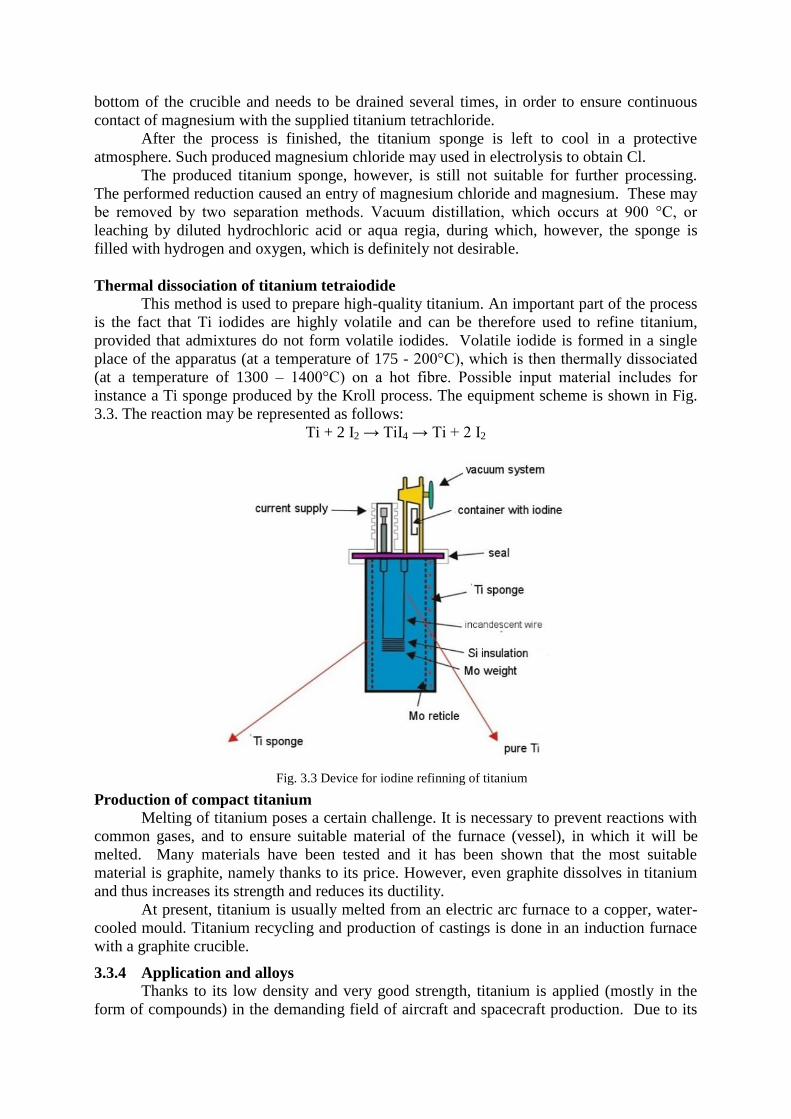
bottom of the crucible and needs to be drained several times, in order to ensure continuous
contact of magnesium with the supplied titanium tetrachloride.
After the process is finished, the titanium sponge is left to cool in a protective
atmosphere. Such produced magnesium chloride may used in electrolysis to obtain Cl.
The produced titanium sponge, however, is still not suitable for further processing.
The performed reduction caused an entry of magnesium chloride and magnesium. These may
be removed by two separation methods. Vacuum distillation, which occurs at 900 °C, or
leaching by diluted hydrochloric acid or aqua regia, during which, however, the sponge is
filled with hydrogen and oxygen, which is definitely not desirable.
Thermal dissociation of titanium tetraiodide
This method is used to prepare high-quality titanium. An important part of the process
is the fact that Ti iodides are highly volatile and can be therefore used to refine titanium,
provided that admixtures do not form volatile iodides. Volatile iodide is formed in a single
place of the apparatus (at a temperature of 175 - 200°C), which is then thermally dissociated
(at a temperature of 1300 – 1400°C) on a hot fibre. Possible input material includes for
instance a Ti sponge produced by the Kroll process. The equipment scheme is shown in Fig.
3.3. The reaction may be represented as follows:
Ti + 2 I2 → TiI4 → Ti + 2 I2
Production of compact titanium
Melting of titanium poses a certain challenge. It is necessary to prevent reactions with
common gases, and to ensure suitable material of the furnace (vessel), in which it will be
melted. Many materials have been tested and it has been shown that the most suitable
material is graphite, namely thanks to its price. However, even graphite dissolves in titanium
and thus increases its strength and reduces its ductility.
At present, titanium is usually melted from an electric arc furnace to a copper, water-
cooled mould. Titanium recycling and production of castings is done in an induction furnace
with a graphite crucible.
3.3.4 Application and alloys
Thanks to its low density and very good strength, titanium is applied (mostly in the
form of compounds) in the demanding field of aircraft and spacecraft production. Due to its
Fig. 3.3 Device for iodine refinning of titanium
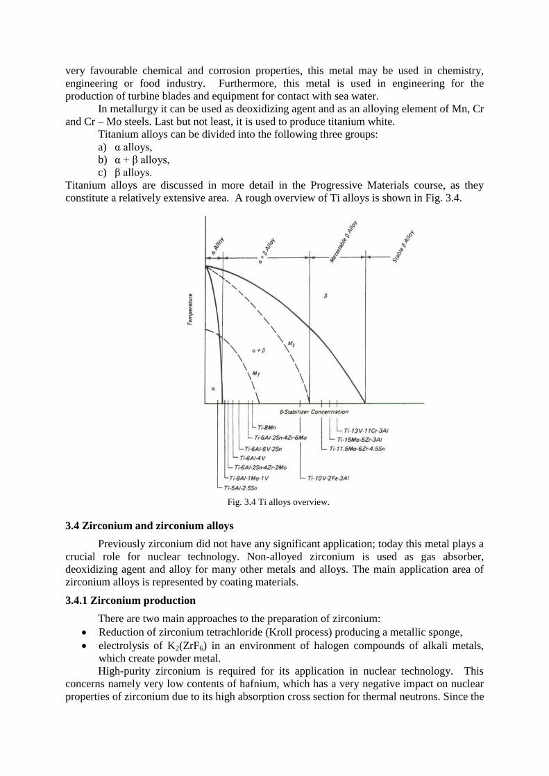
very favourable chemical and corrosion properties, this metal may be used in chemistry,
engineering or food industry. Furthermore, this metal is used in engineering for the
production of turbine blades and equipment for contact with sea water.
In metallurgy it can be used as deoxidizing agent and as an alloying element of Mn, Cr
and Cr – Mo steels. Last but not least, it is used to produce titanium white.
Titanium alloys can be divided into the following three groups:
a) α alloys,
b) α + β alloys,
c) β alloys.
Titanium alloys are discussed in more detail in the Progressive Materials course, as they
constitute a relatively extensive area. A rough overview of Ti alloys is shown in Fig. 3.4.
3.4 Zirconium and zirconium alloys
Previously zirconium did not have any significant application; today this metal plays a
crucial role for nuclear technology. Non-alloyed zirconium is used as gas absorber,
deoxidizing agent and alloy for many other metals and alloys. The main application area of
zirconium alloys is represented by coating materials.
3.4.1 Zirconium production
There are two main approaches to the preparation of zirconium:
Reduction of zirconium tetrachloride (Kroll process) producing a metallic sponge,
electrolysis of K2(ZrF6) in an environment of halogen compounds of alkali metals,
which create powder metal.
High-purity zirconium is required for its application in nuclear technology. This
concerns namely very low contents of hafnium, which has a very negative impact on nuclear
properties of zirconium due to its high absorption cross section for thermal neutrons. Since the
Fig. 3.4 Ti alloys overview.
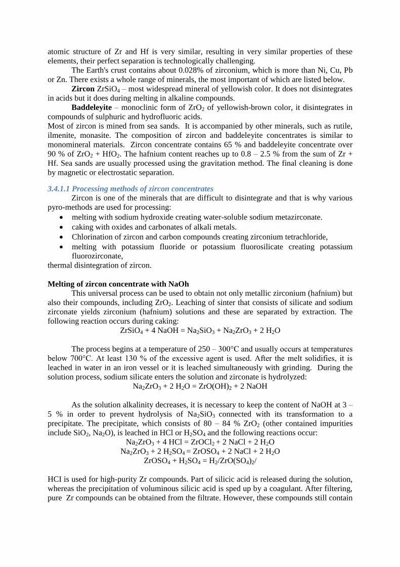
atomic structure of Zr and Hf is very similar, resulting in very similar properties of these
elements, their perfect separation is technologically challenging.
The Earth's crust contains about 0.028% of zirconium, which is more than Ni, Cu, Pb
or Zn. There exists a whole range of minerals, the most important of which are listed below.
Zircon ZrSiO4 – most widespread mineral of yellowish color. It does not disintegrates
in acids but it does during melting in alkaline compounds.
Baddeleyite – monoclinic form of ZrO2 of yellowish-brown color, it disintegrates in
compounds of sulphuric and hydrofluoric acids.
Most of zircon is mined from sea sands. It is accompanied by other minerals, such as rutile,
ilmenite, monasite. The composition of zircon and baddeleyite concentrates is similar to
monomineral materials. Zircon concentrate contains 65 % and baddeleyite concentrate over
90 % of ZrO2 + HfO2. The hafnium content reaches up to 0.8 – 2.5 % from the sum of Zr +
Hf. Sea sands are usually processed using the gravitation method. The final cleaning is done
by magnetic or electrostatic separation.
3.4.1.1 Processing methods of zircon concentrates
Zircon is one of the minerals that are difficult to disintegrate and that is why various
pyro-methods are used for processing:
melting with sodium hydroxide creating water-soluble sodium metazirconate.
caking with oxides and carbonates of alkali metals.
Chlorination of zircon and carbon compounds creating zirconium tetrachloride,
melting with potassium fluoride or potassium fluorosilicate creating potassium
fluorozirconate,
thermal disintegration of zircon.
Melting of zircon concentrate with NaOh
This universal process can be used to obtain not only metallic zirconium (hafnium) but
also their compounds, including ZrO2. Leaching of sinter that consists of silicate and sodium
zirconate yields zirconium (hafnium) solutions and these are separated by extraction. The
following reaction occurs during caking:
ZrSiO4 + 4 NaOH = Na2SiO3 + Na2ZrO3 + 2 H2O
The process begins at a temperature of 250 – 300°C and usually occurs at temperatures
below 700°C. At least 130 % of the excessive agent is used. After the melt solidifies, it is
leached in water in an iron vessel or it is leached simultaneously with grinding. During the
solution process, sodium silicate enters the solution and zirconate is hydrolyzed:
Na2ZrO3 + 2 H2O = ZrO(OH)2 + 2 NaOH
As the solution alkalinity decreases, it is necessary to keep the content of NaOH at 3 –
5 % in order to prevent hydrolysis of Na2SiO3 connected with its transformation to a
precipitate. The precipitate, which consists of 80 – 84 % ZrO2 (other contained impurities
include SiO2, Na2O), is leached in HCl or H2SO4 and the following reactions occur:
Na2ZrO3 + 4 HCl = ZrOCl2 + 2 NaCl + 2 H2O
Na2ZrO3 + 2 H2SO4 = ZrOSO4 + 2 NaCl + 2 H2O
ZrOSO4 + H2SO4 = H2/ZrO(SO4)2/
HCI is used for high-purity Zr compounds. Part of silicic acid is released during the solution,
whereas the precipitation of voluminous silicic acid is sped up by a coagulant. After filtering,
pure Zr compounds can be obtained from the filtrate. However, these compounds still contain

Hf. Hf is separated from Zr by a whole range of methods – most importantly extraction in
organic liquids.
3.4.1.2 Production of zirconium tetrachloride
These processes are commonly used in the preparation of zirconium to prepare the
input material, i.e. zirconium tetrachloride, for production of zirconium using the Kroll
process. These methods are used to process the zircon concentrate, zirconium oxide;
alternatively zircon might be first transformed to carbon nitride and then chlorinated.
ZrSiO4 + 4 C = ZrC + SiO + 3 CO
ZrC (s) + 2 Cl2 (g) = ZrCl4 (g) + C (s) + 846 kJ
ZrN (s) + 2 Cl2 (g) = ZrCl4 (g) + 0,5 N2 (g) + 670 kJ
3.4.1.3 Separation of hafnium from zirconium (dehafnization)
Hafnium as an admixture in zirconium is very undesirable in nuclear technology due
to its high absorption cross section for thermal neutrons. That is why separation of hafnium
from zirconium needs to be included in the preparation process of zirconium compounds for
production of metallic zirconium. The separation is usually performed by a
hydrometallurgical process. Despite the similarity of chemical behaviour of both metals,
certain properties differ significantly and can be therefore used to separate these metals. Used
methods include:
fractional precipitation – this process is based on solubility of the same salts that are
produced by adding a suitable agent to a solution with precious metal ions,
fractional crystallization,
ion exchange,
extraction in organic solutions – this method has the widest application.
3.4.1.4 Production of metallic zirconium by metallothermic method
Metallic zirconium is produced predominantly by metallothermic reduction (see fig.
3.5) of Zr compounds – the most important is reduction of ZrCl4 using Mg. Another method is
electrolytic production from molten alkali halides and K2ZrF6.
Reduction of ZrCl4 by magnesium
This reaction constitutes the basis of the Kroll process. The reduction occurs in steps
in accordance with the following reactions:
ZrCl4 + Mg → ZrCl2 + MgCl2
ZrCl2 + Mg → Zr + MgCl2
These reactions apply only if the input substances are in gaseous state. Mutual reaction of Mg
with ZrCl4 starts at 410 – 470°C; ZrCl4 is reduced only to lower chlorides at temperatures
below 650°C.
Reduction of ZrCl4 by magnesium is a complex heterogeneous process consisting of
several liquid and several solid phases, where the most important processes include wetting,
evaporation, heat and matter exchange.
After the process is completed, the basic mass of the obtained metal consists of a
porous block located at the bottom of the reactor and may have the following composition: Zr
58 wt. %, Mg 32 %, MgCl2 10 %. The next step is vacuum distillation of Mg and MgCl2 at a
temperature of 1000°C. The last step consists of arc melting of the produced material.
The production technology of Zr using reduction of ZrCl4 by magnesium consists of
the following operations:
1. preparation of input substances,
2. reduction,
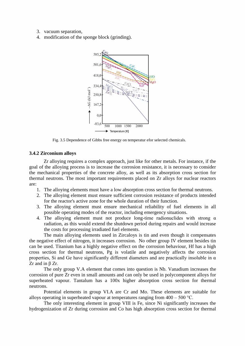
3. vacuum separation,
4. modification of the sponge block (grinding).
3.4.2 Zirconium alloys
Zr alloying requires a complex approach, just like for other metals. For instance, if the
goal of the alloying process is to increase the corrosion resistance, it is necessary to consider
the mechanical properties of the concrete alloy, as well as its absorption cross section for
thermal neutrons. The most important requirements placed on Zr alloys for nuclear reactors
are:
1. The alloying elements must have a low absorption cross section for thermal neutrons.
2. The alloying element must ensure sufficient corrosion resistance of products intended
for the reactor's active zone for the whole duration of their function.
3. The alloying element must ensure mechanical reliability of fuel elements in all
possible operating modes of the reactor, including emergency situations.
4. The alloying element must not produce long-time radionuclides with strong α
radiation, as this would extend the shutdown period during repairs and would increase
the costs for processing irradiated fuel elements.
The main alloying elements used in Zircaloys is tin and even though it compensates
the negative effect of nitrogen, it increases corrosion. No other group IV element besides tin
can be used. Titanium has a highly negative effect on the corrosion behaviour, Hf has a high
cross section for thermal neutrons, Pg is volatile and negatively affects the corrosion
properties, Si and Ge have significantly different diameters and are practically insoluble in α
Zr and in β Zr.
The only group V.A element that comes into question is Nb. Vanadium increases the
corrosion of pure Zr even in small amounts and can only be used in polycomponent alloys for
superheated vapour. Tantalum has a 100x higher absorption cross section for thermal
neutrons.
Potential elements in group VI.A are Cr and Mo. These elements are suitable for
alloys operating in superheated vapour at temperatures ranging from 400 – 500 °C.
The only interesting element in group VIII is Fe, since Ni significantly increases the
hydrogenization of Zr during corrosion and Co has high absorption cross section for thermal
Fig. 3.5 Dependence of Gibbs free energy on temperatur efor selected chemicals.
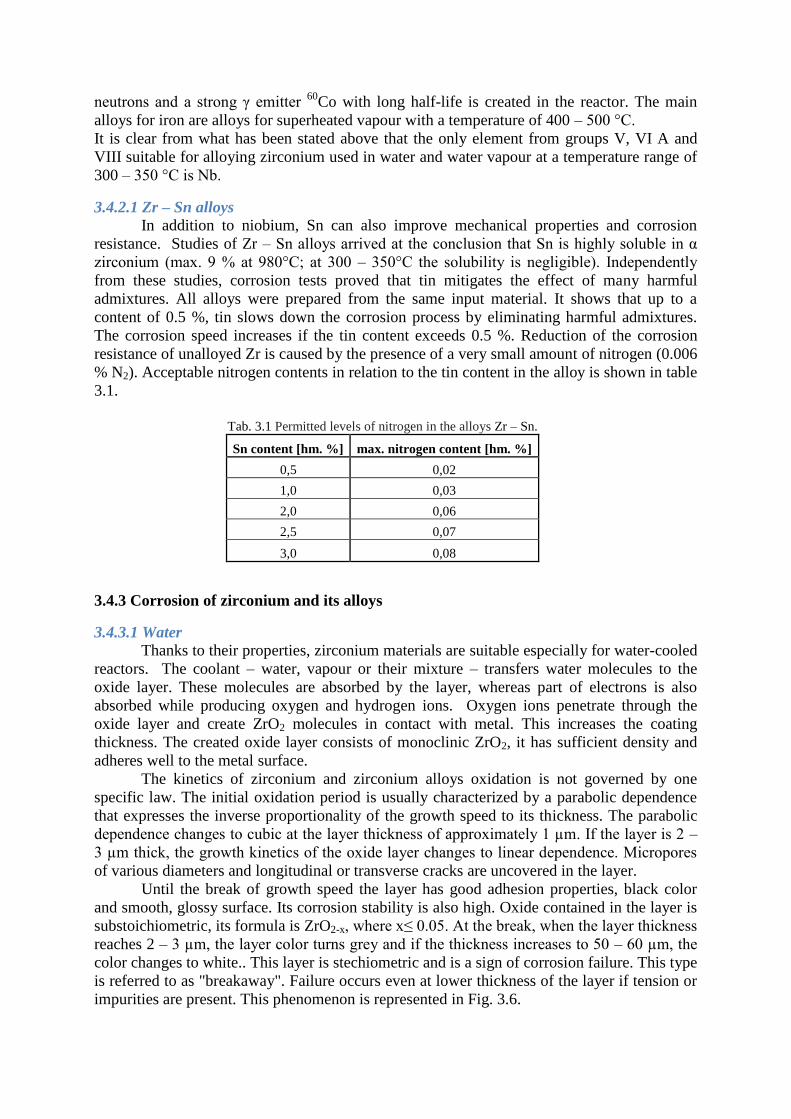
neutrons and a strong γ emitter 60
Co with long half-life is created in the reactor. The main
alloys for iron are alloys for superheated vapour with a temperature of 400 – 500 °C.
It is clear from what has been stated above that the only element from groups V, VI A and
VIII suitable for alloying zirconium used in water and water vapour at a temperature range of
300 – 350 °C is Nb.
3.4.2.1 Zr – Sn alloys
In addition to niobium, Sn can also improve mechanical properties and corrosion
resistance. Studies of Zr – Sn alloys arrived at the conclusion that Sn is highly soluble in α
zirconium (max. 9 % at 980°C; at 300 – 350°C the solubility is negligible). Independently
from these studies, corrosion tests proved that tin mitigates the effect of many harmful
admixtures. All alloys were prepared from the same input material. It shows that up to a
content of 0.5 %, tin slows down the corrosion process by eliminating harmful admixtures.
The corrosion speed increases if the tin content exceeds 0.5 %. Reduction of the corrosion
resistance of unalloyed Zr is caused by the presence of a very small amount of nitrogen (0.006
% N2). Acceptable nitrogen contents in relation to the tin content in the alloy is shown in table
3.1.
3.4.3 Corrosion of zirconium and its alloys
3.4.3.1 Water
Thanks to their properties, zirconium materials are suitable especially for water-cooled
reactors. The coolant – water, vapour or their mixture – transfers water molecules to the
oxide layer. These molecules are absorbed by the layer, whereas part of electrons is also
absorbed while producing oxygen and hydrogen ions. Oxygen ions penetrate through the
oxide layer and create ZrO2 molecules in contact with metal. This increases the coating
thickness. The created oxide layer consists of monoclinic ZrO2, it has sufficient density and
adheres well to the metal surface.
The kinetics of zirconium and zirconium alloys oxidation is not governed by one
specific law. The initial oxidation period is usually characterized by a parabolic dependence
that expresses the inverse proportionality of the growth speed to its thickness. The parabolic
dependence changes to cubic at the layer thickness of approximately 1 µm. If the layer is 2 –
3 µm thick, the growth kinetics of the oxide layer changes to linear dependence. Micropores
of various diameters and longitudinal or transverse cracks are uncovered in the layer.
Until the break of growth speed the layer has good adhesion properties, black color
and smooth, glossy surface. Its corrosion stability is also high. Oxide contained in the layer is
substoichiometric, its formula is ZrO2-x, where x≤ 0.05. At the break, when the layer thickness
reaches 2 – 3 µm, the layer color turns grey and if the thickness increases to 50 – 60 µm, the
color changes to white.. This layer is stechiometric and is a sign of corrosion failure. This type
is referred to as "breakaway". Failure occurs even at lower thickness of the layer if tension or
impurities are present. This phenomenon is represented in Fig. 3.6.
Tab. 3.1 Permitted levels of nitrogen in the alloys Zr – Sn.
Sn content [hm. %] max. nitrogen content [hm. %]
0,5 0,02
1,0 0,03
2,0 0,06
2,5 0,07
3,0 0,08
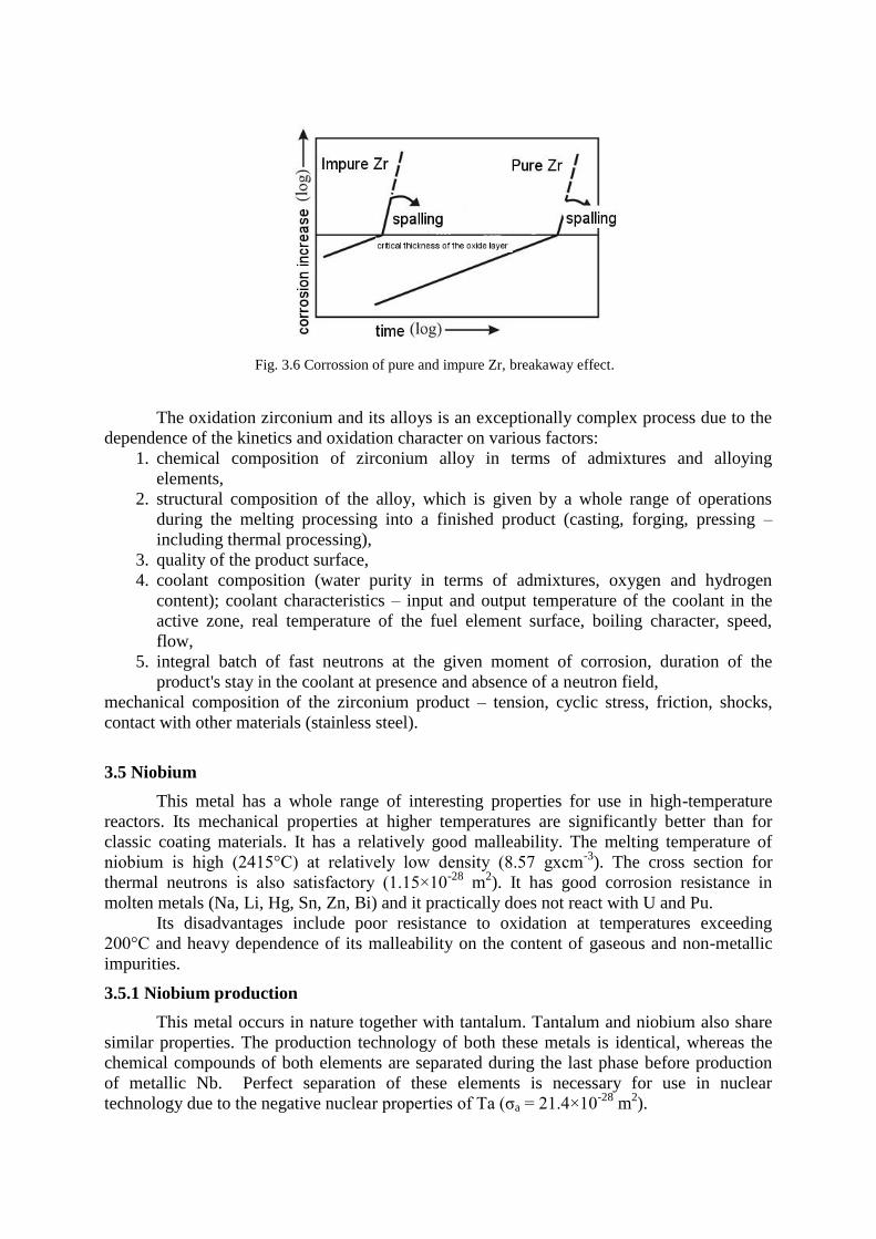
The oxidation zirconium and its alloys is an exceptionally complex process due to the
dependence of the kinetics and oxidation character on various factors:
1. chemical composition of zirconium alloy in terms of admixtures and alloying
elements,
2. structural composition of the alloy, which is given by a whole range of operations
during the melting processing into a finished product (casting, forging, pressing –
including thermal processing),
3. quality of the product surface,
4. coolant composition (water purity in terms of admixtures, oxygen and hydrogen
content); coolant characteristics – input and output temperature of the coolant in the
active zone, real temperature of the fuel element surface, boiling character, speed,
flow,
5. integral batch of fast neutrons at the given moment of corrosion, duration of the
product's stay in the coolant at presence and absence of a neutron field,
mechanical composition of the zirconium product – tension, cyclic stress, friction, shocks,
contact with other materials (stainless steel).
3.5 Niobium
This metal has a whole range of interesting properties for use in high-temperature
reactors. Its mechanical properties at higher temperatures are significantly better than for
classic coating materials. It has a relatively good malleability. The melting temperature of
niobium is high (2415°C) at relatively low density (8.57 gxcm-3
). The cross section for
thermal neutrons is also satisfactory (1.15×10⁻²⁸
m2). It has good corrosion resistance in
molten metals (Na, Li, Hg, Sn, Zn, Bi) and it practically does not react with U and Pu.
Its disadvantages include poor resistance to oxidation at temperatures exceeding
200°C and heavy dependence of its malleability on the content of gaseous and non-metallic
impurities.
3.5.1 Niobium production
This metal occurs in nature together with tantalum. Tantalum and niobium also share
similar properties. The production technology of both these metals is identical, whereas the
chemical compounds of both elements are separated during the last phase before production
of metallic Nb. Perfect separation of these elements is necessary for use in nuclear
technology due to the negative nuclear properties of Ta (σa = 21.4×10⁻²⁸
m2).
Fig. 3.6 Corrossion of pure and impure Zr, breakaway effect.
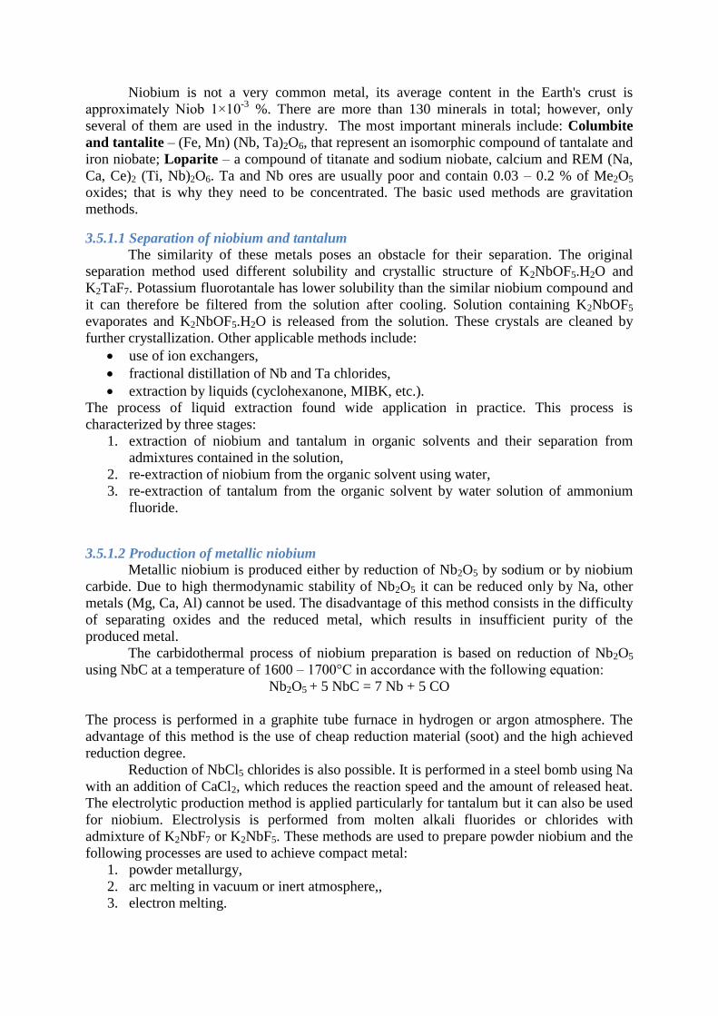
Niobium is not a very common metal, its average content in the Earth's crust is
approximately Niob 1×10⁻³
%. There are more than 130 minerals in total; however, only
several of them are used in the industry. The most important minerals include: Columbite
and tantalite – (Fe, Mn) (Nb, Ta)2O6, that represent an isomorphic compound of tantalate and
iron niobate; Loparite – a compound of titanate and sodium niobate, calcium and REM (Na,
Ca, Ce)2 (Ti, Nb)2O6. Ta and Nb ores are usually poor and contain 0.03 – 0.2 % of Me2O5
oxides; that is why they need to be concentrated. The basic used methods are gravitation
methods.
3.5.1.1 Separation of niobium and tantalum
The similarity of these metals poses an obstacle for their separation. The original
separation method used different solubility and crystallic structure of K2NbOF5.H2O and
K2TaF7. Potassium fluorotantale has lower solubility than the similar niobium compound and
it can therefore be filtered from the solution after cooling. Solution containing K2NbOF5
evaporates and K2NbOF5.H2O is released from the solution. These crystals are cleaned by
further crystallization. Other applicable methods include:
use of ion exchangers,
fractional distillation of Nb and Ta chlorides,
extraction by liquids (cyclohexanone, MIBK, etc.).
The process of liquid extraction found wide application in practice. This process is
characterized by three stages:
1. extraction of niobium and tantalum in organic solvents and their separation from
admixtures contained in the solution,
2. re-extraction of niobium from the organic solvent using water,
3. re-extraction of tantalum from the organic solvent by water solution of ammonium
fluoride.
3.5.1.2 Production of metallic niobium
Metallic niobium is produced either by reduction of Nb2O5 by sodium or by niobium
carbide. Due to high thermodynamic stability of Nb2O5 it can be reduced only by Na, other
metals (Mg, Ca, Al) cannot be used. The disadvantage of this method consists in the difficulty
of separating oxides and the reduced metal, which results in insufficient purity of the
produced metal.
The carbidothermal process of niobium preparation is based on reduction of Nb2O5
using NbC at a temperature of 1600 – 1700°C in accordance with the following equation:
Nb2O5 + 5 NbC = 7 Nb + 5 CO
The process is performed in a graphite tube furnace in hydrogen or argon atmosphere. The
advantage of this method is the use of cheap reduction material (soot) and the high achieved
reduction degree.
Reduction of NbCl5 chlorides is also possible. It is performed in a steel bomb using Na
with an addition of CaCl2, which reduces the reaction speed and the amount of released heat.
The electrolytic production method is applied particularly for tantalum but it can also be used
for niobium. Electrolysis is performed from molten alkali fluorides or chlorides with
admixture of K2NbF7 or K2NbF5. These methods are used to prepare powder niobium and the
following processes are used to achieve compact metal:
1. powder metallurgy,
2. arc melting in vacuum or inert atmosphere,,
3. electron melting.
3.5.2 Niobium processing
Powder niobium is processed similarly as Mo and W. The process is divided into the
following two operations: powder pressing and caking. The pressing depends on the grain size
and pressure ranges between 250 and 750 MPa. Caking is realized in vacuum (simultaneously
with cleaning due to volatilization of certain admixtures). The caking temperature is 1400 –
1500°C and lasts for 2 hours. The final caking is done at 2300°C.
Niobium melting is performed in an electric arc furnace with a consumable electrode
in a copper water-cooled crystallizer. The electrode is produced by caking powder niobium.
Electron melting has a wide range of advantages: the metal can be overheated and maintained
in melted state in high vacuum, the metal can be used in any form (powder, sponge, etc.), it is
possible to prepare super alloys. The use of high vacuum also leads to evaporation of certain
admixtures, which results in refining of the metal.
Niobium produced by powder metallurgy or electron melting in particular has good
malleability. It can be easily processed with all chipless processing methods, such as pressing,
drawing, rolling, etc. Cast niobium might contain inclusions. Common impurities, such as
carbon or nitrogen, reduce the niobium workability and increase its hardness.
3.5.3 Mechanical properties of niobium
Mechanical properties of niobium are highly influenced by the content of impurities. It
is strongly affected by elements that create interstitial solid solutions with niobium. These
include namely carbon, oxygen and nitrogen that might cause brittleness even at normal
temperature. The effect of oxygen is represented in Fig. 3.7. The deformation ability of
niobium is very negatively affected already at 0.03 % of carbon, 0.3 % of oxygen and 0.1 %
of nitrogen. Suitable alloying elements can be used to improve the mechanical properties of
niobium. Systems relevant for nuclear technology are binary systems Nb – V, Nb – Zr, Nb –
Mo, Nb – Ti and ternary systems Nb – Ti – Cr, Nb – Ti – Mo.
3.5.4 Niobium corrosion
In terms of corrosion, niobium is not very resistant in contact with air at higher
temperatures. Starting at 200 °C, a thin layer of oxides is created on the surface and it is stable
up to 400 °C. At a temperature exceeding 400 °C, the created Nb2O5 is porous and does not
protect the metal against oxidation. In addition to oxidation, oxygen is also diffused in the
metal, causing embrittlement of niobium. Niobium forms NbN and Nb2N nitrides together
with nitrogen. Absorption of nitrogen causes significant embrittlement of niobium already at
400 °C. Created nitrides are very stable and can be removed only by annealing in vacuum at
Fig. 3.7 Influence of oxygen on hardness of unalloyed Nb.
temperatures of 2000 °C. Hydrogen is also absorbed by niobium, which results in
embrittlement.
However, it is possible to significantly improve the resistance to oxidation by adding
V, Ti, Cr, Mo or W. Further improvement is also achieved by ternary systems. These alloys
still need to be protected by silicide coatings for long-term use in oxidation environments at
increased temperatures. Niobium alloys with zirconium or vanadium are suitable to water
vapour environment, where mostly zirconium alloys with relatively low strength values are
used. Ternary alloys Nb – Ti – Cr can also be used.
The behaviour of niobium in molten metals is very interesting. Especially important is
the good corrosion resistance of niobium in liquid sodium or in the sodium – potassium
system. However, the corrosion resistance is conditioned by low oxygen content (up to 5
ppm).
3.6 Vanadium
3.6.1 Properties of vanadium and vanadium alloys
Vanadium is a steel-grey, hard metal that can be ground and polished. Physical and
namely mechanical properties are greatly affected by impurities constituting interstitial solid
solutions. These include namely oxygen, nitrogen, hydrogen and carbon. These elements
cause brittleness of vanadium. In order to ensure vanadium is malleable, the maximum
content of oxygen and nitrogen combined must not exceed 0.2 wt. %. Carbon does not
significantly affect the hardness up to a content of 0.25. Mechanical properties of vanadium
may be modified by alloying. The disadvantage of most of the alloying elements is the fact
that the resulting alloys are usually brittle. Malleable alloys are V – Ti and V – Zr.
Vanadium has a relatively low density of 6.1 g.cm-3
and a high melting temperature
1910°C. It has a KPC lattice. In compact state, vanadium does not react with air, water and
alkaline hydroxides at a normal temperature. It is resistant to acids with oxidizing effects –
with the exception of HF. It dissolves in aqua regia and HNO3. It easily creates basic and
acidic radicals that can form the central atom in polyacid together with elements of groups IV
V. VI. A VIII. of the period table. Its most important compounds include oxides, chloride,
sulfates and sulfides.
3.6.2 Preparation technology of vanadium
The content of vanadium in the Earth's crust (0.2 %) is higher than the content of
copper, zinc and lead. However, the disadvantage is that it rarely occurs in rich finding sites.
Usually it is accompanied by other minerals and it often creates complex minerals, most
importantly:
Roscoelite KV2/AlSi3O10/(OH)2 – a mica containing approximately 32.4 % of V2O3. It
occurs in certain poor dikes, namely in the US.
Patronite V2S5 – contains 19 – 25 % of V2O5, can be found namely in Peru.
Vanadite – Pb5(VO4)3.Cl – contains 19.4 % of V2O5, located in the oxidizing zone of
lead-zinc ores.
Carnotite K2O.2UO3.V2O5.3H2O – contains 19.8 % of V2O5. Largest sites of these
minerals are located in the US.
Due to the fact that it accompanies iron ores in hundredths, it can also be produced
from slag, to which it passes during the iron industry and metallurgic processes. Various
production processes are used due to the different character of vanadium ores and materials.
Alkaline methods
The methods for processing of ores or concentrates are based on their melting
with NaCl or Na2CO3, during which vanadium is transformed to sodium vanadate, which is
soluble in water. After leaching in water, it precipitates from the aqueous solution by slight
acidification by H2SO4 in the form of V2O5 and with purity of 85 – 92 %. The rest are alkalis.
Acidic methods
This group of methods is based on leaching by H2SO4 and transferring vanadium to
the solution in the form of sulfates. Vanadium is precipitated from the solution in the form of
V2O5 by neutralization of the solution using alkalis or Fe vanadate using iron(II) oxide or
FeSO4.
Chloridation roasting in the presence of NaCl. Vanadium, which is present in the
trivalent form in ores and slag from blast furnaces, is transformed to the pentavalent form
during roasting. Roasting is performed on ground material at temperatures of 800 – 900°C.
2 Fe(V2O3) + ½ O2 ↔ 2 V2O5 + Fe2O3
In the next phase, V2O5 is transformed to sodium vandate, which dissolves in water at about
80°C. H2SO4 is added to the solution and the solution pH is maintained between 1 – 3.
Sodium hexavandate, which can be used to prepare V2O5 after it is dried, is then released
from the solution.
After carnotite ores are processed, acidic and alkaline leaching methods may be used.
Acidic methods provide higher yield of vanadium; however, they may be used only if the
content of carbonates in the ore is not too high. These methods also place higher
requirements on the equipment due to the aggressive environment.
Processing of carnotite ores by carbonate leaching offers certain advantages:
the solution is not so aggressive and the equipment may be made of a cheaper
material,
the method is especially suitable for ores with high content of CaCO3,
Na2CO3 are easily regenerated by bubbling through.
Its disadvantages include lower leaching speed and the fact that sulfide minerals react with
carbonate and therefore increase its consumption. Acidic sodium carbonate is added to soda
after the reaction to reduce the alkalinity of the solution.
Simultaneous leaching of vanadium and uranium complicates their selective
separation from the solution. Nowadays, namely ion exchangers and extractions are used in
organic solutions.
Another interesting method is leaching of vanadium in the solution in the form of
V2O3 by hydrogen reduction.
2 NaVO3 + 2 H2 + 2 NaHCO3 = V2O3 + 2 Na2CO3 + 3 H2O
The reduction is usually performed at a temperature of 150 °C and pressure of 1.4 MPA in the
presence of Ni as a catalyzer. Nickel is separated from V2O3 by magnetic separation.
3.6.2.1 Production of metallic vanadium
One of the most used methods is the reduction of V2O5 using calcium. It is performed
in accordance with the following reaction:
5 Ca + V2O5 = 5 CaO + 2 V + 1463 kJ
The reaction is strongly exothermic and is moderated by CaCl2, which at the same time
transforms CaO to liquid slag. The process itself is realized in a steel bomb in a magnetized
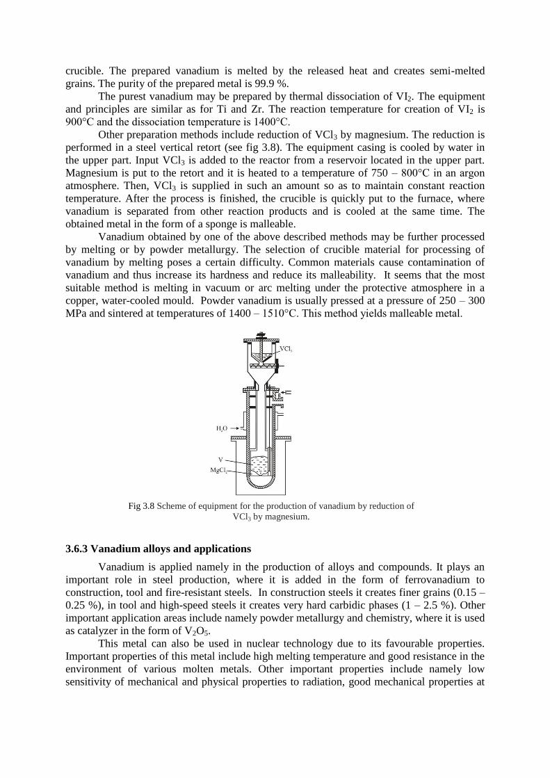
crucible. The prepared vanadium is melted by the released heat and creates semi-melted
grains. The purity of the prepared metal is 99.9 %.
The purest vanadium may be prepared by thermal dissociation of VI2. The equipment
and principles are similar as for Ti and Zr. The reaction temperature for creation of VI2 is
900°C and the dissociation temperature is 1400°C.
Other preparation methods include reduction of VCl3 by magnesium. The reduction is
performed in a steel vertical retort (see fig 3.8). The equipment casing is cooled by water in
the upper part. Input VCl3 is added to the reactor from a reservoir located in the upper part.
Magnesium is put to the retort and it is heated to a temperature of 750 – 800°C in an argon
atmosphere. Then, VCl3 is supplied in such an amount so as to maintain constant reaction
temperature. After the process is finished, the crucible is quickly put to the furnace, where
vanadium is separated from other reaction products and is cooled at the same time. The
obtained metal in the form of a sponge is malleable.
Vanadium obtained by one of the above described methods may be further processed
by melting or by powder metallurgy. The selection of crucible material for processing of
vanadium by melting poses a certain difficulty. Common materials cause contamination of
vanadium and thus increase its hardness and reduce its malleability. It seems that the most
suitable method is melting in vacuum or arc melting under the protective atmosphere in a
copper, water-cooled mould. Powder vanadium is usually pressed at a pressure of 250 – 300
MPa and sintered at temperatures of 1400 – 1510°C. This method yields malleable metal.
3.6.3 Vanadium alloys and applications
Vanadium is applied namely in the production of alloys and compounds. It plays an
important role in steel production, where it is added in the form of ferrovanadium to
construction, tool and fire-resistant steels. In construction steels it creates finer grains (0.15 –
0.25 %), in tool and high-speed steels it creates very hard carbidic phases (1 – 2.5 %). Other
important application areas include namely powder metallurgy and chemistry, where it is used
as catalyzer in the form of V2O5.
This metal can also be used in nuclear technology due to its favourable properties.
Important properties of this metal include high melting temperature and good resistance in the
environment of various molten metals. Other important properties include namely low
sensitivity of mechanical and physical properties to radiation, good mechanical properties at
Fig 3.8 Scheme of equipment for the production of vanadium by reduction of
VCl3 by magnesium.
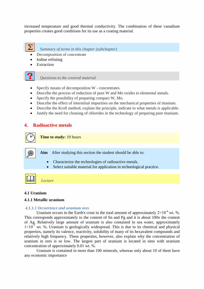
increased temperature and good thermal conductivity. The combination of these vanadium
properties creates good conditions for its use as a coating material.
Summary of terms in this chapter (subchapter)
Decomposition of concentrate
Iodine refiniing
Extraction
Questions to the covered material
Specify means of decomposition W - concentrates.
Describe the process of reduction of pure W and Mo oxides to elemental metals.
Specify the possibility of preparing compact W, Mo.
Describe the effect of interstitial impurities on the mechanical properties of titanium.
Describe the Kroll method, explain the principle, indicate to what metals is applicable.
Justify the need for cleaning of chlorides in the technology of preparing pure titanium.
4. Radioactive metals
Time to study: 10 hours
Aim After studying this section the student should be able to:
Characterize the technologies of radioactive metals.
Select suitable material for application in technological practice.
Lecture
4.1 Uranium
4.1.1 Metallic uranium
4.1.1.1 Occurrence and uranium ores
Uranium occurs in the Earth's crust in the total amount of approximately 2×10⁻⁴
wt. %.
This corresponds approximately to the content of Sn and Pg and it is about 100x the content
of Ag. Relatively large amount of uranium is also contained in sea water, approximately
1×10⁻⁷
wt. %. Uranium is geologically widespread. This is due to its chemical and physical
properties, namely its valence, reactivity, solubility of many of its hexavalent compounds and
relatively high frequency. These properties, however, also explain why the concentration of
uranium in ores is so low. The largest part of uranium is located in sites with uranium
concentration of approximately 0.01 wt. %.
Uranium is contained in more than 100 minerals, whereas only about 10 of them have
any economic importance
4.1.1.2 Uranium production
Processing of uranium ores
Most of the locations of uranium provides only ores with low content of uranium that
need to be enriched before they can be processed to metallic uranium. Uranium ores can be
enriched by classic methods, such as separation by heavy liquids, gravitation or flotation.
Minerals such as uraninite, carnotite and torbernite are enriched by gravitation or by heavy
liquids. The flotation method is used for example for uranothorite.
Radiometric enrichment of uranium ores can be used as an example. This process can
be realized on radiometric separators. This type of separator is schematically represented in
Fig. 4.1.
Leaching of uranium ores
The most common method of uranium ore processing consists of hydrometallurgical
treatment using acid or carbonate leaching.
Acid leaching
Acid leaching of uranium ores is the most important method of converting the ores to
a solution. It is used to process ores containing the following oxides: Th, Ti, Ta, Nb and
REM. If the ore contains tetravalent uranium, the acid leaching is done using an oxidant
(MnO2, HNO3, Fe3+
, VO2+
, etc.). Before the leaching itself, the ore is annealed in order to
ensure dissolution of organic substances, oxidization of sulphides, dissolution of carbonates
and removal of arsenic and sulphur. Salts are added to ores before leaching; uranium oxides
and salts create uranates.
Such modified ore is then processed in acid, usually H2SO4. Dissolution of uranium
can be done for instance in accordance with the following reaction:
U3O8 + 4 H2SO4 + MnO2 → 3 UO2SO4 + MnSO4 + 4 H2O
Uranium is obtained from this uranium solution, which also contains a whole range of
additional metals (Fe, Mn, Ni, Al, Cu,…), by precipitation, sorption or extraction. Uranium
precipitates from acid solutions in the form of hydroxides through neutralization of the
solutions using bases, ammonia or calcium oxides or magnesium oxide. Sometimes uranium
precipitates in the form of phosphate after the reduction of uranium to quadrivalent form
using iron or aluminium.
Sorption methods consists of capturing uranium using the ionic exchange process.
This process is based on differing ability of ions to undergo ionic exchange with ionic
exchangers (artificial resin). Sorption by anion-exchange resins (anex), where complete
uranium anion /UO2(SO4)3/4-
is absorbed, is also a common method. Extraction methods are
1 - feed tray
2 – feeding system
3 – belt feeder
4 – device for increasing of the speed and stability
5 – dividing mechanism
6 – display
7 – counter
8 – main transporter
9 – light source
10 – concentrate
11 – waste
12 – electrical equipment Fig. 4.1 Radiometric separator.
used to obtain uranium from low-concentration solutions. Extraction agents include TBF
(tributyl phosphate), MIBK (methyl isobutyl ketone) and a whole range of other organic
dissolvents. Optimum extraction environment for H2SO4 leaching includes phosphoric acid
esters and alkylamines.
Preparation of uranium compounds
The most important starting materials for the uranium industry include UO2, UF4 and
UF6. Fluorides UF4 and UF6 are required for the production of metallic uranium and for
isotope enrichment of natural uranium with isotope 235
U.
Production of UO2
Uranium dioxide can be produced by thermal decay of UO2(NO3)2 or (NH4)2U2O7.
Thermal decay of UO2(NO3)2 to UO3 is ended by the reduction of UO3 by hydrogen.
UO2(NO3)2 . 6 H2O 300°𝐶→ UO3 + 2 NO2 + ½ O2 + 6 H2O
UO3 + H2 → (500-700°C) UO2 + H2O
Precipitation of diuranate by ammonia takes places within the pH range of 7-8 in accordance
with the following reaction: 2 UO2(NO3)2 + 6 NH3 + 6 H2O → (NH4)2U2O7 + 4 NH4NO3 + 3 H2O
Decay occurs at a temperature of 300 °C:
(NH4)2U2O7 300°𝐶→ 2 UO3 + 2 NH3 + H2O
Production of UF4
The following reactions can apply here:
UO2 (s) + 4 HF (g) 550°𝐶→ UF4 (s) + 2 H2O (g) + Q
3 UO3 (s) + 6 NH3 (g) + 12 HF (g) 500−700°𝐶→ 3 UF4 (s) + 9 H2O (g) + N2 (g) + 4 NH3 (g)
3 UO3 (s) + 6 NH4HF2 (g) 700°𝐶→ 3 UF4 (s) + 9 H2O (g) + N2 (g) + 3 NH3 (g)
Production of UF6
The main used process is fluorination of UF4 by elementary fluorine, which consumes
the least fluorine and ensures the highest product quality. Other options include:
2 UO3 + 6 F2 → 2 UF6 + 3 O2
U3O8 + 9 F2 → 3 UF6 + 4 O2
Methods of direct fluorination of metallic uranium using ClF3, BrF3, BrF5 have also been
elaborated. The reaction can be represented as follows:
U + 2 BrF3 → UF6 + Br2
Br2 + 3 F2 → 2 BrF3
The production of UF6 from UF4 without the addition of fluorine is also interesting:
2 UF4 + O2 800°𝐶→ UF6 + UO2F2
UO2F2 + H2 → UO2 + 2 HF
UO2 + 4 HF → UF4 + 2 H2O
Enrichment of uranium
A whole range of processes have been developed for uranium enrichment. Some of
these technologies are commonly used in practice (diffusion, centrifuge), others are in the
stage of pilot operation, etc.
Gas diffusion
This process is based on different diffusion speeds of the isotope compound of UF6
through porous membranes. Gaseous UF6 is compressed by compressors and the
concentration is slightly shifted towards the lighter isotope on the low-pressure side of the
membrane due to a little higher diffusion speed of lighter uranium molecules. The scope of
the separation effect can be theoretically determined using molecular ratios of isotopes 238
U
and 235
U. The maximum theoretical value of the elementary separation coefficient is 1.0043.
In practice its value is usually 1.004.
In theory the diffusion enrichment process can be described based on a different
weight and consequently also different speed of the compound passing through the
membrane. The following relations apply here.
E = M. v2
2
M1 . v12 = M2 . v2
2 v1
v2=
M2
M1= α (separační součinitel)
The following relation applies for the enrichment of uranium isotopes in form of UF6:
αU= √
M238 UF6M235 UF6
=1,0043
Since the separation coefficient is so low, large volume flows need to be processed in
order to ensure the economy of the process. Since only negligible enrichment is achieved in
one separation step, it is necessary to repeat a large number of these diffusion processes,
whereas UF6 is compressed again by compressors in each separation step and the compression
heat needs to be removed. The production of uranium enriched to 3 % 235
U, which is used in
nuclear reactors, can be used as a typical examples – about 1000 – 1500 separation steps are
needed in this process. The diffusion equipment includes a large number of separation
elements of relatively large sizes connected in a series. Repeated compression of the operating
gas and dissipation of the compression heat result in high energy demands reaching up to
2300 – 2500 kWh/kg JSP.
Gas centrifuges
Gaseous UF6 is supplied to the operating area by a high-speed rotor. Centrifuge forces
cause lighter isotopes to concentrate in the area around the spinning, while heavier isotopes
are cumulated near the rotor wall and can be separated by fraction. This separation of isotopes
is significantly supported by thermally induced counter current.
The size of the separation factor depends on the difference of molecular weight, the
squared volume speed and the rotor length. It has been observed that separation factors 1.2 –
1.5 are usually achieved. Due to this relatively high separation factor it is necessary to repeat
each separation step 10 – 15 times in order to achieve 3 % uranium enrichment by isotope 235
U. Since the mass flow volume of one centrifuge is relatively low, it is necessary to operate
a large number of parallel-connected centrifuges in order to ensure an economic and efficient
flow. Unlike diffusion cascades, centrifuge cascades are characterized by a small number of
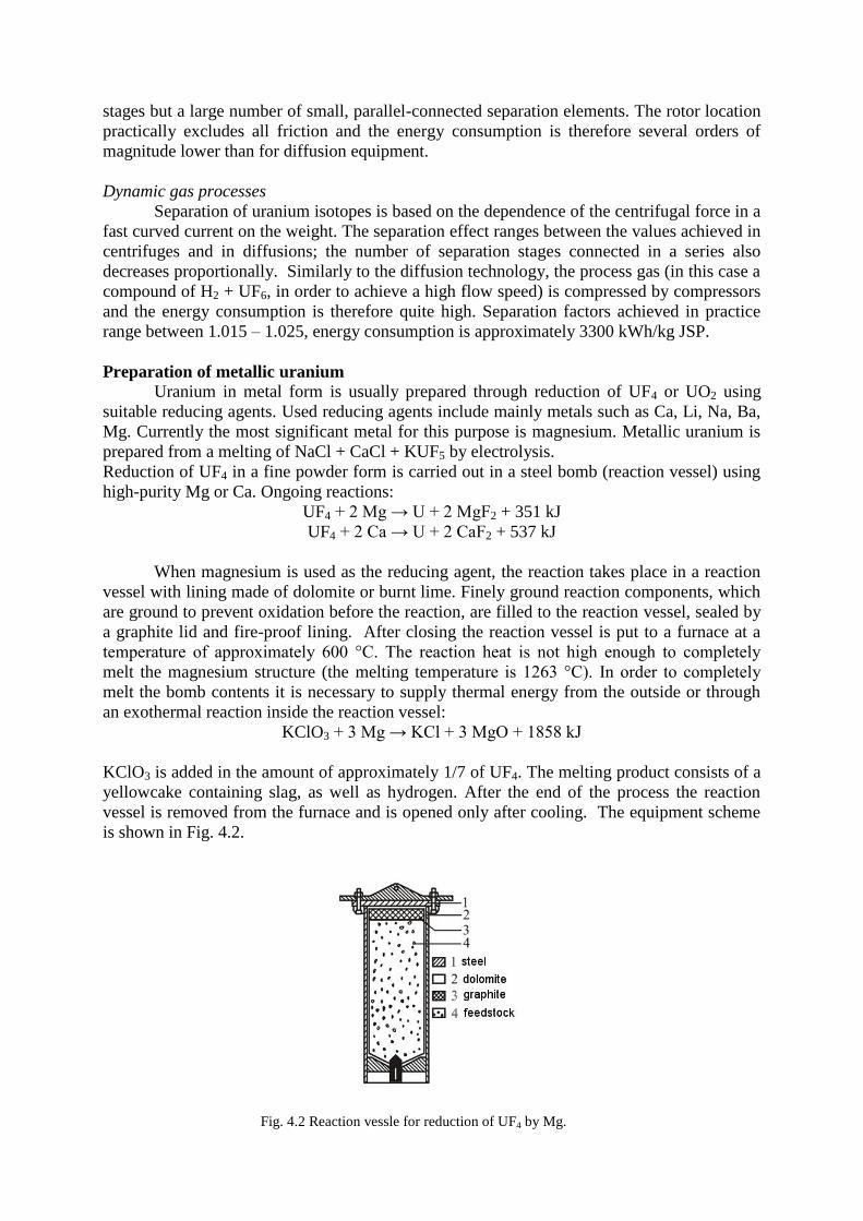
stages but a large number of small, parallel-connected separation elements. The rotor location
practically excludes all friction and the energy consumption is therefore several orders of
magnitude lower than for diffusion equipment.
Dynamic gas processes
Separation of uranium isotopes is based on the dependence of the centrifugal force in a
fast curved current on the weight. The separation effect ranges between the values achieved in
centrifuges and in diffusions; the number of separation stages connected in a series also
decreases proportionally. Similarly to the diffusion technology, the process gas (in this case a
compound of H2 + UF6, in order to achieve a high flow speed) is compressed by compressors
and the energy consumption is therefore quite high. Separation factors achieved in practice
range between 1.015 – 1.025, energy consumption is approximately 3300 kWh/kg JSP.
Preparation of metallic uranium
Uranium in metal form is usually prepared through reduction of UF4 or UO2 using
suitable reducing agents. Used reducing agents include mainly metals such as Ca, Li, Na, Ba,
Mg. Currently the most significant metal for this purpose is magnesium. Metallic uranium is
prepared from a melting of NaCl + CaCl + KUF5 by electrolysis.
Reduction of UF4 in a fine powder form is carried out in a steel bomb (reaction vessel) using
high-purity Mg or Ca. Ongoing reactions:
UF4 + 2 Mg → U + 2 MgF2 + 351 kJ
UF4 + 2 Ca → U + 2 CaF2 + 537 kJ
When magnesium is used as the reducing agent, the reaction takes place in a reaction
vessel with lining made of dolomite or burnt lime. Finely ground reaction components, which
are ground to prevent oxidation before the reaction, are filled to the reaction vessel, sealed by
a graphite lid and fire-proof lining. After closing the reaction vessel is put to a furnace at a
temperature of approximately 600 °C. The reaction heat is not high enough to completely
melt the magnesium structure (the melting temperature is 1263 °C). In order to completely
melt the bomb contents it is necessary to supply thermal energy from the outside or through
an exothermal reaction inside the reaction vessel:
KClO3 + 3 Mg → KCl + 3 MgO + 1858 kJ
KClO3 is added in the amount of approximately 1/7 of UF4. The melting product consists of a
yellowcake containing slag, as well as hydrogen. After the end of the process the reaction
vessel is removed from the furnace and is opened only after cooling. The equipment scheme
is shown in Fig. 4.2.
Fig. 4.2 Reaction vessle for reduction of UF4 by Mg.
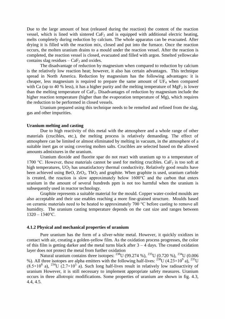
Due to the large amount of heat (released during the reaction) the content of the reaction
vessel, which is lined with sintered CaF2 and is equipped with additional electric heating,
melts completely during reduction by calcium. The whole apparatus can be evacuated. After
drying it is filled with the reaction mix, closed and put into the furnace. Once the reaction
occurs, the molten uranium drains to a mould under the reaction vessel. After the reaction is
completed, the reaction vessel is closed, evacuated and filled with argon. Smelted yellowcake
contains slag residues – CaF2 and oxides.
The disadvantage of reduction by magnesium when compared to reduction by calcium
is the relatively low reaction heat; however, it also has certain advantages. This technique
spread in North America. Reduction by magnesium has the following advantages: it is
cheaper, less magnesium is required to prepare the same amount of UF4 when compared
with Ca (up to 40 % less), it has a higher purity and the melting temperature of MgF2 is lower
than the melting temperature of CaF2. Disadvantages of reduction by magnesium include the
higher reaction temperature (higher than the evaporation temperature of Mg), which requires
the reduction to be performed in closed vessels.
Uranium prepared using this technique needs to be remelted and refined from the slag,
gas and other impurities.
Uranium melting and casting Due to high reactivity of this metal with the atmosphere and a whole range of other
materials (crucibles, etc.), the melting process is relatively demanding. The effect of
atmosphere can be limited or almost eliminated by melting in vacuum, in the atmosphere of a
suitable inert gas or using covering molten salts. Crucibles are selected based on the allowed
amounts admixtures in the uranium.
Uranium dioxide and fluorite spar do not react with uranium up to a temperature of
1700 °C. However, these materials cannot be used for melting crucibles. CaF2 is too soft at
high temperatures, UO2 has unsatisfactory thermal conductivity. Relatively good results have
been achieved using BeO, ZrO2, ThO2 and graphite. When graphite is used, uranium carbide
is created, the reaction is slow approximately below 1600°C and the carbon that enters
uranium in the amount of several hundreds ppm is not too harmful when the uranium is
subsequently used in reactor technology.
Graphite represents a suitable material for the mould. Copper water-cooled moulds are
also acceptable and their use enables reaching a more fine-grained structure. Moulds based
on ceramic materials need to be heated to approximately 700 °C before casting to remove all
humidity. The uranium casting temperature depends on the cast size and ranges between
1320 – 1340°C.
4.1.2 Physical and mechanical properties of uranium
Pure uranium has the form of a silver-white metal. However, it quickly oxidizes in
contact with air, creating a golden-yellow film. As the oxidation process progresses, the color
of this film is getting darker and the metal turns black after 3 – 4 days. The created oxidation
layer does not protect the metal from further oxidation
Natural uranium contains three isotopes: 238
U (99.274 %), 235
U (0.720 %), 234
U (0.006
%). All three isotopes are alpha emitters with the following half-lives: 238
U (4.23×10⁹ a),
235U
(8.5×10⁸ a),
234U (2.7×10
5 a). Such long half-lives result in relatively low radioactivity of
uranium However, it is still necessary to implement appropriate safety measures. Uranium
occurs in three allotropic modifications. Some properties of uranium are shown in fig. 4.3,
4.4, 4.5.
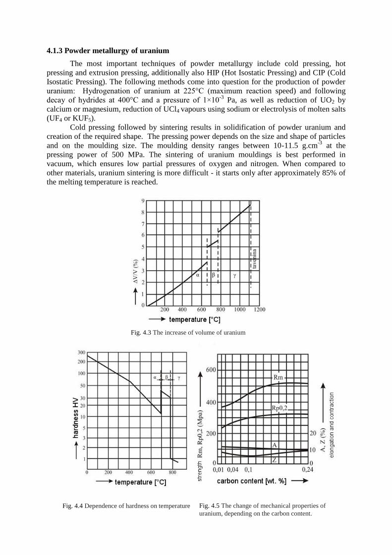
4.1.3 Powder metallurgy of uranium
The most important techniques of powder metallurgy include cold pressing, hot
pressing and extrusion pressing, additionally also HIP (Hot Isostatic Pressing) and CIP (Cold
Isostatic Pressing). The following methods come into question for the production of powder
uranium: Hydrogenation of uranium at 225°C (maximum reaction speed) and following
decay of hydrides at 400°C and a pressure of 1×10⁻³
Pa, as well as reduction of UO2 by
calcium or magnesium, reduction of UCl4 vapours using sodium or electrolysis of molten salts
(UF4 or KUF5).
Cold pressing followed by sintering results in solidification of powder uranium and
creation of the required shape. The pressing power depends on the size and shape of particles
and on the moulding size. The moulding density ranges between 10-11.5 g.cm-3
at the
pressing power of 500 MPa. The sintering of uranium mouldings is best performed in
vacuum, which ensures low partial pressures of oxygen and nitrogen. When compared to
other materials, uranium sintering is more difficult - it starts only after approximately 85% of
the melting temperature is reached.
Fig. 4.3 The increase of volume of uranium
v závislosti na teplotě.
Fig. 4.4 Dependence of hardness on temperature Fig. 4.5 The change of mechanical properties of
uranium, depending on the carbon content.
Hot pressing can yield almost theoretical density of uranium. In order to sufficiently
utilize the material plasticity, pressing is carried out in the upper section of thermal stability of
the α phase. Again, protective atmospheres or vacuum are used for these processes.
4.1.4 Uranium alloys
4.1.4.1 Uranium alpha alloys
This type of alloys has been developed with the aim to decrease the volume growth –
swelling. It is assumed that homogeneous dispersion solidification by fine particles can lead
to the creation of additional centres for capturing fission gas products. These dispersion
particles can be obtained by adding a small amount of elements with low solubility in alpha
uranium, such as Si, Fe, Al. These alloys, possibly also Cr, are thermally processed by
hardening from beta phase (temperatures of 720 – 730°C) into water or oil and annealing for
several hours at upper temperatures of the alpha phase (500 – 600°C). This thermal
processing leads to:
finer grains and lower risk of striation,
creation of a fine second phase precipitate,
removal of the forming texture in the alpha phase.
The increased swelling resistance is contributed to the presence of a fine precipitate.
Alloy elements dissolve completely (Fe-Si) or partially (Al) by heating up to the beta-uranium
zone. Quenching creates an over-saturated solid solution, from which fine particles (UAl2,
U6Fe etc.) of a size of approximately 100×10-10
m are released during the following tempering
(500 – 600°C). Volume density of particles is approximately 1013
– 1015
in 1 cm3, which
corresponds to the density of bubble nuclei of fissile gas in irradiated uranium. It is assumed
that this fine precipitate has a beneficial effect on fine nucleation of bubbles or prevents their
movement and accumulation by preventing the movement of dislocations and grain
boundaries.
4.1.4.2 Uranium gamma alloys
Nb, Mo, Ti and Zr cause stabilization of the gamma phase uranium. Metastable
gamma phase uranium created in U-Mo and U-Nb systems is the most passive phase for the
transformation, which is why these alloys are only usable in the metastable state. They will be
discussed in more details in the chapter dedicated to Ti and Zr.
Uranium gamma alloys are typically represented by the uranium alloy with 10 – 14 wt.
% of Mo, whereas the weight content of Mo above 5 % already allows maintaining the
metastable gamma phase uranium up to normal temperatures (assuming that the cooling speed
of the alloy is not too slow). Isotropic gamma phase uranium is not subject to radiation growth
and that is why there is no risk of striation or radiation creep. The main reason of size changes
in these alloys is gas swelling. All uranium gamma alloys with solid gamma solution
containing Mo, Nb, Ti and Zr usually undergo homogenizing annealing after their production.
The annealing process lasts 24 hours and is done at a temperature of approximately 900 °C.
Another group of γ uranium alloys consists of alloys obtained by regeneration of uranium
irradiated in fast radiators. When this uranium is processed by melting under oxidation slag,
volatile elements and REM are removed almost completely, whereas elements Mo, Ru, Rh,
Pa, Nb, Te, i.e. the fission products, remain in the uranium and zirconium is separated only
partially. Elements that remain in uranium are called "fissium" and uranium alloys with these
elements are called uranium fissium alloys.
4.1.7 Uranium alloys – ceramic fuels
With the development of high-power energy reactors, ever increasing requirements are
placed on fissile materials, such as high operating temperature, high irradiation, dimensional
stability and the maximum possible safety. Uranium or its alloys were not able to meet these
requirements. This is due to the fact that metallic uranium undergoes phase transformations at
temperatures exceeding 600 °C leading to significant deterioration of its mechanical
properties and volume changes caused by recrystallization. It is therefore clear that alloys can
be used for fuel elements only at temperatures not exceeding 600 °C. This shortcoming can be
removed using the following processes:
thermal treatment and alloying,
application of ceramic fuels.
Ceramic fuels have a whole range of advantages when compared to metal fuels, such
as:
significant thermal and radiation resistance,
high melting temperatures,
phase stability in a wide interval of temperatures (provided that suitable processing is
used),
weak dependence of the material strength on temperature,
relatively small expansion,
dimensional stability under the conditions of the required reactor output,
higher irradiation depth of the fissile component in comparison with metallic uranium.
Disadvantages of ceramic fuels include mainly:
high brittleness and low resistance to temperature shocks,
necessity to use special coating materials that are significantly more expensive than Al
or Mg alloys,
lower thermal conductivity (especially at higher temperatures) in comparison with
metallic uranium,
hard formability of ceramics.
Production of uranium dioxide UO2
In practice, uranium dioxide can be produced using three methods.
1. Thermal decay of uranyl nitrate followed by reduction by hydrogen, split ammonia or
carbon monoxide:
2. Precipitation by ammonia from water solutions of uranyl nitrate while producing
ammonium diuranate, which is thermally decayed. This processes produces U3O8
which is then reduced to UO2 as in the first example.
3. Precipitation by hydrogen peroxide from water solutions of uranyl nitrate while
producing hydrated uranium peroxide, which is again thermally decayed and reduced
to UO2.
Properties of uranium dioxide UO2
The listed values characterize uranium dioxide as hard and brittle ceramic material.
Elasticity constants decrease with increasing temperature, porosity and the O:U ratio. The
bending strength decreases with increasing grain size and porosity. Increasing temperature
causes an increase of the bending strength for fine porosity and small grains; for gross
porosity and large grain size increasing temperature causes a decrease of the bending strength.
The transition temperature of malleable – brittle fracture is 1250°C for UO2. Hardness
increases with the O:U ratio.
Mechanical properties of UO2 therefore heavily depend on structural factors and these
factors change depending on preparation methods and processing temperatures. Another
important factor influencing the properties of UO2 is the so-called oxygen index. It is the
numerical deviation from the oxygen index that should equal 2. Precise designation of oxides
is usually UO2+-x´. Changes of the oxygen index influence the thermal conductivity of fuel,
melting temperature of fuel, transition temperature of brittle - malleable fracture, swelling,
creep, etc. During creep tests samples of sintered UO2,06 and UO2,16 deformed already at
800°C, whereas the corresponding temperature for UO2 is 1600°C.
Preparation of compact UO2
Uranium dioxide is used in two forms for fuel elements. The first form consists of
compact bodies, tablets prepared by pressing and sintering or hot-pressing. The second used
form is powder condensed by vibration or rotation forging. Pressing and sintering are the most
elaborated preparation procedures of compact UO2. Pressing is done at a pressure ranging
from 4 – 7×10² MPa with the use of plasticizers and binding materials. The sintering process
is carried out at temperatures ranging between 1600 – 1750°C for 1 – 4 hours. The process
also includes pre-annealing at 600 – 800°C if binding agents are used. Pores are reduced
during sintering through diffusion of vacancies along grain boundaries, whereas the speed of
the process is determined by the concentration gradient of these vacancies. Sintering is also
affected by UO2 stoichiometry and is accelerated by even slight increase of oxygen in sulphur
dioxide to the density of UO2,02, whereas any further increase of the oxygen content does not
significantly affect the sintering process. This effect is usually explained by the increase of the
O2-
diffusion coefficient when compared to U self-diffusion. The sintering process is also
affected by the atmosphere. High density UO2 is obtained in hydrogen; worse results are
achieved in N2 and Ar. UO2 with high density can be achieved in vacuum. The sintering
method itself has been designed so that it can be applied even without sintering additives and
yields high density values.
4.2 Thorium
Unlike uranium, thorium does not belong to fissile materials. However, during its
irradiation by slow neutrons, nuclear reactions occur and lead to the creation of fissile isotope 233
U with long half-life. Thorium is therefore referred to as a fertile material – isotope 233
U is
created by the following reaction:
Th (n, γ) → Th (−β, 23 min) → Pa (−β, 2791233
90233
90232 min ) → U92
233
Due to the fact that thorium reserves significantly exceed uranium reserves, it is
reasonable to expect that thorium will be used much more in the future. However, a
significant disadvantage of thorium in this breeding process is the high required enrichment of
fuel by isotope 235
U or 239
Pu. Another difficulties are summarized by the following list:
low speed of fuel creation in thorium fuel cycle 𝑇ℎ → 𝑈92232
90232 ,
increased radioactivity of 233
U in comparison with 235
U and 239
Pu, which is caused by
accumulation of isotope 232
U and its daughter isotopes,
fuel poisoning by 232
Pa, which has a large cross section for neutron capture.
4.2.1 Occurrence, ores and their enrichment
In terms of occurrence in nature, thorium holds 35th place among other elements. As
far as geochemical properties are concerned, this metals has a lot in common with rare-earth
metals (REM), Zr and U, whereas their beds are usually complex. This metal occurs in rocks
in scattered state in the form of the following minerals: monazite, ortite, zircon, xenotime,
thorianite, etc. There are about 120 known minerals containing thorium.
4.2.2 Thorium production
Monazite concentrates are processed in order to obtain compounds of thorium, REM,
uranium and phosphorus. The production technology includes the following processes:
1. Decay of a concentrate to thorium and REM compounds that are soluble in inorganic
acids.
2. Conversion of thorium and REM into a solution.
3. Separation of thorium and REM from phosphorus.
4. Split of thorium and REM.
A whole range of methods have been elaborated for the first operation:
processing by concentrated sulphur acid – so-called sulphate method,
processing by a concentrated solution of sodium hydroxide – basic method,
melting with sodium hydroxide,
caking with soda ash,
melting with fluorosilicates,
chlorination,
phosphate reduction at high temperatures.
The biggest challenge in the thorium production is its separation from REM, since
their properties are very similar. These metals are separated based on small differences in
chemical properties of certain compounds. However, these methods cannot yield the purity
required for nuclear technology. That is why extraction and sorption methods are used in the
next step.
4.2.2.1 Preparation of pure thorium compounds
Due to the fact that the prepared concentrates contain not only thorium but also a
substantial amount of REM and other admixtures, it is necessary to include a cleaning
process. Cleaning methods of thorium compounds after monazite processing can be divided
into two groups:
1. Methods of selective precipitation and solution.
2. Methods of selective extraction by organic solvents (significant application in
practice).
Methods of selective precipitation and solution
This group of methods includes the following procedures.
Fractional crystallization
This procedure uses different basicity of thorium and REM. Ammonia solution is
added in small amounts to a hot solution of these metals in order to achieve even
concentration of hydrogen ions. This process yields Th(OH)4, containing only about 1 - 2 %
of REM.
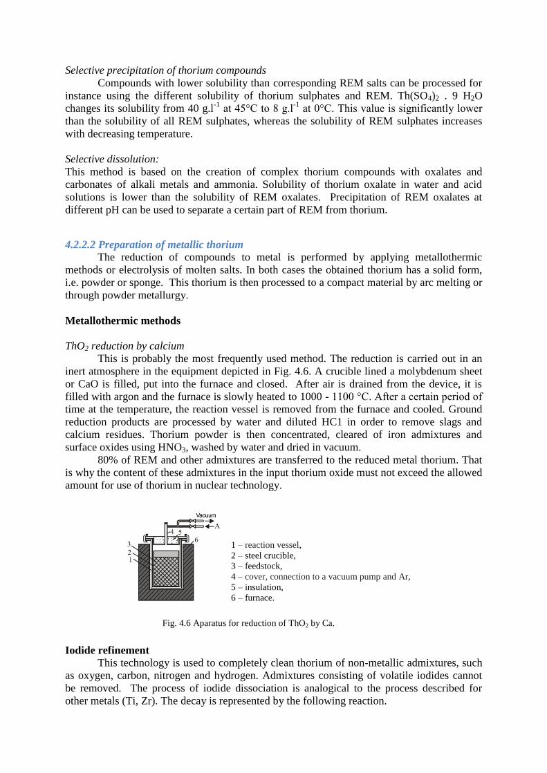
Selective precipitation of thorium compounds
Compounds with lower solubility than corresponding REM salts can be processed for
instance using the different solubility of thorium sulphates and REM. Th(SO4)2 . 9 H2O
changes its solubility from 40 g.l-1
at 45°C to 8 g.l-1
at 0°C. This value is significantly lower
than the solubility of all REM sulphates, whereas the solubility of REM sulphates increases
with decreasing temperature.
Selective dissolution:
This method is based on the creation of complex thorium compounds with oxalates and
carbonates of alkali metals and ammonia. Solubility of thorium oxalate in water and acid
solutions is lower than the solubility of REM oxalates. Precipitation of REM oxalates at
different pH can be used to separate a certain part of REM from thorium.
4.2.2.2 Preparation of metallic thorium
The reduction of compounds to metal is performed by applying metallothermic
methods or electrolysis of molten salts. In both cases the obtained thorium has a solid form,
i.e. powder or sponge. This thorium is then processed to a compact material by arc melting or
through powder metallurgy.
Metallothermic methods
ThO2 reduction by calcium
This is probably the most frequently used method. The reduction is carried out in an
inert atmosphere in the equipment depicted in Fig. 4.6. A crucible lined a molybdenum sheet
or CaO is filled, put into the furnace and closed. After air is drained from the device, it is
filled with argon and the furnace is slowly heated to 1000 - 1100 °C. After a certain period of
time at the temperature, the reaction vessel is removed from the furnace and cooled. Ground
reduction products are processed by water and diluted HC1 in order to remove slags and
calcium residues. Thorium powder is then concentrated, cleared of iron admixtures and
surface oxides using HNO3, washed by water and dried in vacuum.
80% of REM and other admixtures are transferred to the reduced metal thorium. That
is why the content of these admixtures in the input thorium oxide must not exceed the allowed
amount for use of thorium in nuclear technology.
Iodide refinement
This technology is used to completely clean thorium of non-metallic admixtures, such
as oxygen, carbon, nitrogen and hydrogen. Admixtures consisting of volatile iodides cannot
be removed. The process of iodide dissociation is analogical to the process described for
other metals (Ti, Zr). The decay is represented by the following reaction.
1 – reaction vessel,
2 – steel crucible,
3 – feedstock,
4 – cover, connection to a vacuum pump and Ar,
5 – insulation,
6 – furnace.
Fig. 4.6 Aparatus for reduction of ThO2 by Ca.
4.2.3 Thorium properties
Thorium is a soft metal with the appearance of steel. However, its hardness is similar
to silver. In term of physical properties, this metal has a whole range of advantages in
comparison with uranium – namely high thermal conductivity and low thermal expansion
coefficient. Its specific weight is significantly lower. Its main advantages include the cubic
crystallic structure, thanks to which cyclic thermal stress or radioactive radiation do not cause
any significant dimensional and shape changes that are characteristic for uranium. Its melting
temperature is approximately 1750 °C. Thorium has a strong affinity to carbon, nitrogen and
hydrogen. These elements strongly affect its properties.
4.2.5 Thorium alloys
Pure thorium does provide sufficient strength properties at increased temperatures and
that is why it is alloyed with other suitable elements. The selection of suitable alloys needs to
take into consideration its absorption cross section for thermal neutrons.
This metal has a strong tendency to create intermetallic phases and only certain metals
are dissolved in larger amounts. The most important fissile materials are Th – U alloys.
Thorium alloys are produced by melting in a crucible or an arc furnace, alternatively by
powder metallurgy. The most important alloying elements include U, Pu, Al, C, Be, V, Si,
Mo, Ni, Sn, Zr.
Summary of terms in this chapter (subchapter)
Uranium production
Thorium production
Oxidic uranium preparation
Metallothermic processes of production
Questions to the covered material
Production of UO2 and its importance for nuclear power.
List and characterize the basic types of uranium alloys.
Briefly describe the technology of uranium metal.
Used literature that may be used for further study
KURSA, M., KUCHAŘ, L.: Kovy jaderných reaktorů. VŠB Ostrava, 1984, 399 s.
KMEŤOVÁ, D.: Hutníctvo drahých a vzácných kovov. Košice, 1984, 320 s.
KURSA, M.: Hutnictví ušlechtilých a vzácných kovů. Návody do cvičení. VŠB
Ostrava, 1986, 103 s.
Gold: Scinece and applications, eds. Christopher Corti and Richard Holliday, CRC
Press, Taylor & Francis Group, ISBN: 978-1-4200-6523-7.
GUPTA, CH. K.: Chemical Metallurgy, Principles and Practice, WILEY-VCH Verlag
GmbH & Co. KGaA, Weinheim, 2003, ISBN: 3-527-30376-6.
ČUGAJEV, L.V. a kol.: Metallurgija blagorodnych metallov. Metallurgija, Moskva,
1987, 431s.
DONACHIE, J.M.: Titanium: A Technical Guide, ASM International, 2000, ISBN-13:
978-0871706867.

CHANDLER, H.: Metallurgy for the non-metalurgists, ASM International, 1998,
ISBN-13: 978-0-87170-652-2.